US8672733B2 - Ventilation airflow rate control - Google Patents
Ventilation airflow rate controlDownload PDFInfo
- Publication number
- US8672733B2 US8672733B2US11/703,518US70351807AUS8672733B2US 8672733 B2US8672733 B2US 8672733B2US 70351807 AUS70351807 AUS 70351807AUS 8672733 B2US8672733 B2US 8672733B2
- Authority
- US
- United States
- Prior art keywords
- motor
- air
- airflow rate
- representation
- present
- Prior art date
- Legal status (The legal status is an assumption and is not a legal conclusion. Google has not performed a legal analysis and makes no representation as to the accuracy of the status listed.)
- Active, expires
Links
Images


Classifications
- F—MECHANICAL ENGINEERING; LIGHTING; HEATING; WEAPONS; BLASTING
- F04—POSITIVE - DISPLACEMENT MACHINES FOR LIQUIDS; PUMPS FOR LIQUIDS OR ELASTIC FLUIDS
- F04D—NON-POSITIVE-DISPLACEMENT PUMPS
- F04D27/00—Control, e.g. regulation, of pumps, pumping installations or pumping systems specially adapted for elastic fluids
- F04D27/004—Control, e.g. regulation, of pumps, pumping installations or pumping systems specially adapted for elastic fluids by varying driving speed
- F—MECHANICAL ENGINEERING; LIGHTING; HEATING; WEAPONS; BLASTING
- F24—HEATING; RANGES; VENTILATING
- F24F—AIR-CONDITIONING; AIR-HUMIDIFICATION; VENTILATION; USE OF AIR CURRENTS FOR SCREENING
- F24F11/00—Control or safety arrangements
- F24F11/70—Control systems characterised by their outputs; Constructional details thereof
- F24F11/72—Control systems characterised by their outputs; Constructional details thereof for controlling the supply of treated air, e.g. its pressure
- F24F11/74—Control systems characterised by their outputs; Constructional details thereof for controlling the supply of treated air, e.g. its pressure for controlling air flow rate or air velocity
- F24F11/77—Control systems characterised by their outputs; Constructional details thereof for controlling the supply of treated air, e.g. its pressure for controlling air flow rate or air velocity by controlling the speed of ventilators
- Y—GENERAL TAGGING OF NEW TECHNOLOGICAL DEVELOPMENTS; GENERAL TAGGING OF CROSS-SECTIONAL TECHNOLOGIES SPANNING OVER SEVERAL SECTIONS OF THE IPC; TECHNICAL SUBJECTS COVERED BY FORMER USPC CROSS-REFERENCE ART COLLECTIONS [XRACs] AND DIGESTS
- Y02—TECHNOLOGIES OR APPLICATIONS FOR MITIGATION OR ADAPTATION AGAINST CLIMATE CHANGE
- Y02B—CLIMATE CHANGE MITIGATION TECHNOLOGIES RELATED TO BUILDINGS, e.g. HOUSING, HOUSE APPLIANCES OR RELATED END-USER APPLICATIONS
- Y02B30/00—Energy efficient heating, ventilation or air conditioning [HVAC]
- Y02B30/70—Efficient control or regulation technologies, e.g. for control of refrigerant flow, motor or heating
Definitions
- HVACheating, ventilating, and air-conditioning
- HVACHeating, ventilating, and air-conditioning
- HVAC equipment and unitssuch as air handlers, air conditioning units, heat pumps, furnaces, and the like have been mass produced in a variety of sizes and configurations, and appropriate sizes have been selected to be installed in various buildings having different or unique HVAC ductwork.
- HVAC unitshave had single speed blowers designed to provide adequate flow for typical ductwork.
- different buildings with different ductworkhave had varying amounts of airflow restriction, and prior art HVAC units installed in such systems have often provided too much or too little flow in installations where the ductwork provided more or less airflow restriction than the HVAC designers had anticipated.
- actual airflow rateshave been insufficient, resulting in reduced energy efficiency as a result of reduced transfer of heat, inadequate heating or cooling of the space, higher utility bills than expected, frost formation on evaporator coils, or a combination thereof, as examples.
- HVAC unitshave produced more noise than desired, consumed more fan energy than necessary, provided excessive airflow to the space causing excessive air movement within the space, or a combination thereof, as further examples.
- HVAC unitshave been used that have had variable speed fans or blowers.
- Some such systemshave been used in variable air volume (VAV) systems, for example, and have used variable speed drive units, such as variable frequency AC drive units and variable voltage DC systems.
- VAVvariable air volume
- variable-speed fanshave been used to compensate for variations in airflow restriction in HVAC ductwork.
- thishas typically required the attention of skilled personnel who have measured airflow rates using handheld instruments such as Pitot tubes, measured airflow rates at registers, performed calculations, or a combination thereof, for example.
- technicians of the necessary skill levelare not available for this purpose or would add too much cost to the expense of installing and commissioning an HVAC unit.
- prior art systemsthat provided for compensating for variations in airflow restriction within HVAC ductwork typically required specialized measurement equipment for measuring airflow rates directly, for example, which added cost and complexity to HVAC systems and, at least in some cases, reduced reliability of HVAC systems. Further, prior art systems did not operate continuously and therefore did not compensate for changes in airflow restriction that occurred after the system was commissioned, such as partial clogging of filters, user adjustment of registers, and modifications to the ductwork, as examples.
- HVAC equipment, systems, and methodsthat provide for some degree of compensation for variations in ductwork restriction in different installations.
- needs and potential for benefitexist for such equipment, systems, and methods that at least partially compensate for changes in airflow restriction that occurred after the system was commissioned, such as partial clogging of filters, user adjustment of registers, and modifications to the ductwork, as examples.
- needs and potential for benefitexist for such equipment, systems, and methods that are inexpensive, utilize existing components (e.g., to a greater degree), are reliable, and are easy to place into service by typical installation personnel.
- This inventionprovides, among other things, air handling units for ventilating an at-least partially enclosed space, air-conditioning units, methods of controlling an airflow rate within a ventilation system, and methods of providing more-constant performance of air conditioning units, as examples.
- Different embodimentsadjust or vary speed or torque of a blower or fan motor based on inputs such as electric current of the motor or pressure (e.g., absolute or differential pressure) within the system, and speed or torque of the motor.
- Various embodiments of the inventionprovide as an object or benefit that they partially or fully address one or more of the needs, potential areas for improvement or benefit, or functions described herein, for instance.
- Specific embodimentsprovide as an object or benefit, for instance, that they at-least partially provide for control of airflow rates within ventilation systems, provide HVAC equipment, systems, and methods that provide for some degree of compensation for variations in ductwork restriction in different installations, or a combination thereof, for example.
- Various embodimentsprovide equipment, systems, and methods that are reasonably inexpensive, utilize existing components to at least some degree, are reasonably reliable, and can reasonably be placed into service by typical installation personnel, for example, typical service personnel in residential installations. Further still, particular embodiments provide equipment, systems, and methods that maintain (at least to some extent) cooling or heating effectiveness (or both) over a range of varying ductwork airflow restriction, that provide for reduced energy consumption in comparison with certain alternatives, that provide for reduced noise, that avoid insufficient or excessive airflow rates, that provide for sufficient airflow through evaporator coils to prevent frost formation, that continuously compensate for variations in airflow restriction, or a combination thereof, as further examples.
- Some specific embodimentsprovide such equipment, systems, and methods in residential applications, for example, such as residential air-conditioning units, heat pumps, furnaces, and the like, and many of these embodiments are suitable to be installed by typical installers of such equipment.
- Certain embodiments of the inventionhave as an object or benefit that they provide for control of airflow rate of fans having variable speed or torque motors using only one motor current sensor.
- such an objectincludes providing a substantially constant or constant airflow rate.
- an object or benefitis to improve or optimize airflow control performance with reduced or minimal computational resource requirements.
- Other objects and benefits of various embodiments of the inventionmay be apparent to a person of skill in the art having studied this document.
- this inventionprovides air-handling units for ventilating an at-least partially enclosed space.
- the air-handling unitincludes a first fan configured to blow air through the air-handling unit to the space, an electric first motor connected to and configured to turn the first fan, and a control system configured to use a first input and a second input to control and vary speed or torque of the first motor.
- the first inputis a representation of the speed or of the torque of the first motor
- the second inputis a representation of an electric current of the first motor or of a pressure, for example, within the air-handling unit or ventilation system.
- control systemis configured to vary the speed or the torque of the first motor to obtain a substantially fixed airflow rate through the air-handling unit over a range of varying amount of airflow restriction, for example.
- some embodimentsfurther include a first heat-transfer coil configured and positioned so that the air blown by the first fan through the air-handling unit passes through the first heat-transfer coil.
- a fluidpasses through the first heat-transfer coil, and heat is transferred via the first heat-transfer coil between the air and the fluid.
- the air-handling unitis an air conditioning unit, for example, the fluid is a refrigerant, and the first heat-transfer coil is an evaporator coil.
- such an air-handling unitfurther includes, within an enclosure for the air-handling unit, an expansion valve, a compressor, an electric second motor connected to and configured to turn the compressor, a condenser coil, a second fan configured to blow air through the condenser coil, and an electric third motor connected to and configured to turn the second fan.
- the second inputis the representation of the electric current of the first motor
- the first motorhas a first electrical power lead and a second electrical power lead
- the air-handling unitfurther includes a current sensor that includes a coil surrounding either the first electrical power lead or the second electrical power lead.
- air conditioning unitsfor providing more-consistent airflow in a variety of residential structures having a variety of different ductwork configurations with different amounts of airflow restriction.
- air conditioning unitsinclude an evaporator, a first fan configured to blow or move air through the evaporator or air conditioning unit to the space, an electric first motor connected to and configured to turn the first fan, and a control system configured to use a first input and a second input to control and vary the speed or the torque of the first motor.
- the control systemis configured to repeatedly or continuously sample the first input and the second input and vary the speed or the torque of the first motor to obtain a substantially fixed airflow rate through the air conditioning unit or the evaporator over a range of varying amount of airflow restriction.
- the first inputis a representation of the speed or the torque of the first motor
- the second inputis a representation of the electric current of the first motor or a pressure within the air conditioning unit.
- the first inputis a representation of the speed of the first motor
- the second inputis a representation of the electric current of the first motor.
- the first inputis a representation of the torque of the first motor
- the second inputis a representation of the electric current of the first motor.
- this inventionprovides various methods, such as methods of controlling an airflow rate within a ventilation system.
- the methodincludes at least the steps of starting a fan motor within the ventilation system, operating the fan motor at a present input setting that includes a present motor speed setting or a present motor torque setting, and sampling a first representation of a first present parameter of the ventilation system that includes a present speed of the fan motor or a present torque of the fan motor.
- the methodincludes a step of sampling a second representation of a second present parameter of the ventilation system.
- the second present parameterincludes a present current of the fan motor or a present pressure within the ventilation system.
- This example of a methodfurther includes a step of calculating a third representation of a present airflow rate within the ventilation system using the first representation and the second representation, and a step of calculating a new input setting using the third representation of the present airflow rate and a fourth representation of a target airflow rate.
- the new input settingis predicted to provide a new airflow rate within the ventilation system that is closer to the target airflow rate than the present airflow rate.
- This example of a methodalso includes the steps of changing the present input setting to the new input setting, and repeating at least a plurality of times the steps of sampling the first representation, sampling the second representation, calculating the third representation of the present airflow rate, calculating the new input setting, and changing the present input setting to the new input setting.
- such a methodfurther includes, for example, after the step of calculating the third representation, a step of evaluating whether the present airflow rate is within a range of the target airflow rate, and if the present airflow rate is not within the range of the target airflow rate, then the step of calculating the new input setting includes using a first formula to calculate the new input setting. On the other hand, if the present airflow rate is within the range of the target airflow rate, in this embodiment, then the step of calculating the new input setting includes using a second formula to calculate the new input setting. In this example, the first formula converges on the target airflow rate more quickly than the second formula, for example.
- the step of sampling the first representation of the first present parameterincludes sampling the second representation at least a plurality of times and evaluating stabilization of the second present parameter.
- the third representation(which is used to calculate the new input setting, to which the present input setting is changed) is calculated using samples of the second representation taken after the second present parameter has substantially stabilized.
- the present input settingis initially selected to provide a predicted airflow rate within the ventilation system that is less than the target airflow rate
- the new input settingis selected to provide a new airflow rate that is less than the target airflow rate, to avoid overshooting the target airflow rate.
- the target airflow rateis fixed at a constant value.
- Another example of an embodimentis a method of providing more-consistent performance of air conditioning units that are mass produced and installed in a variety of structures having a variety of different ductwork configurations with different amounts of airflow restriction.
- the methodincludes at least a step of obtaining or providing at least a plurality air conditioning units, each air conditioning unit having a cooling coil, a fan configured to blow air through the cooling coil and to the structure, and an electric fan motor connected to and configured to turn the fan.
- this exampleincludes (in any order with the previously identified step) a step of obtaining or providing a control system configured use the method described above to control the fan motor to at least partially compensate for the different amounts of the airflow restriction of the different ductwork configurations.
- each of the plurality of air conditioning unitsfurther includes an expansion valve, a compressor, a compressor motor connected to and configured to turn the compressor, a condenser coil, a condenser fan configured to blow air through the condenser, and a condenser fan motor connected to and configured to turn the condenser fan.
- the cooling coilis an evaporator coil
- the present input settingis initially selected to provide a predicted airflow rate within the ventilation system that is less than the target airflow rate.
- the new input settingis selected to provide a new airflow rate that is less than the target airflow rate, to avoid overshooting the target airflow rate.
- various embodimentsfurther include a step of providing an alarm that the airflow restriction of the ductwork is excessive, for example, if the third representation of the present airflow rate fails to reach a predetermined value.
- the first present parameteris the present speed of the fan motor
- the first present parameteris the present torque of the fan motor
- the second present parameteris the present current of the fan motor
- the second present parameteris the present pressure within the ventilation system, or a combination thereof, for example.
- Various combinationsprovide significant advantages in particular situations. Further, some embodiments of these methods may also include other steps described herein.
- Other embodiments of the inventioninclude various combinations of the features and limitations described herein or known to people of skill in the art of HVAC systems and equipment design, and controls for such systems and equipment.
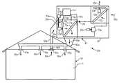
- FIG. 1is a block diagram illustrating, among other things, an air-handling unit that is also an air conditioning unit, and a ventilation system, that illustrates various examples of embodiments of the invention
- FIG. 2is a flow chart illustrating examples of various methods, including, as examples, methods of controlling a fan in a ventilation system, methods of controlling an airflow rate within a ventilation system, and methods of providing more-constant performance of air conditioning units that are mass produced for installation in a variety of structures having a variety of different ductwork configurations with different amounts of airflow restriction;
- FIG. 3is a graph illustrating an example of a relationship between airflow rate, motor speed, and motor electric current for an example of an embodiment of the invention wherein motor speed and motor current are used as inputs or parameters to control airflow rate;
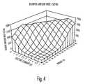
- FIG. 4is a graph illustrating an example of a relationship between airflow rate, motor torque, and motor electric current for an example of an embodiment of the invention wherein motor torque and motor current are used as inputs or parameters to control airflow rate;
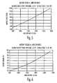
- FIG. 5is a graph illustrating an example of a relationship between airflow rate and motor speed, for an example of a ventilation system
- FIG. 6is a graph illustrating an example of a relationship between airflow rate and motor torque, for an example of a ventilation system
- FIG. 7is a flow chart illustrating examples of various methods, including, among other things, methods of providing more-constant performance of air conditioning units that are mass produced for installation in a variety of structures having a variety of different ductwork configurations with different amounts of airflow restriction.
- this inventionprovides improvements to heating, ventilating, and air-conditioning (HVAC) systems, methods, and controls.
- HVACheating, ventilating, and air-conditioning
- Various embodimentscontrol airflow rates based on certain input parameters, and several embodiments use two particular input parameters.
- airflow ratesare controlled using motor speed and motor electric current, for example.
- airflow ratesare controlled using motor torque and motor electric current, as another example.
- the system or method of the inventionincludes a target airflow rate, and the system or method measures the motor electric current and determines the speed or torque at which the motor should run, as an example. Further, in some embodiments, the system or method converts a speed- or torque-based motor blower assembly into a constant airflow rate device independent of duct system design. And in certain embodiments, a pressure may be used as an input instead of motor electric current.
- airflow ratemay be varied to at least partially compensate for differing airflow restriction in ductwork, for example.
- air handlerssuch as air conditioning units may be mass produced in common configurations and installed in different buildings or structures with different ductwork configurations having different amounts of airflow restriction.
- airflow rates from the air handlersmay be controlled to at least partially compensate for the different amounts of airflow restriction of the different ductwork configurations.
- the speed, torque, or both, of a fan motormay be varied to obtain a substantially constant or fixed airflow rate over a range of varying amounts of airflow restriction.
- Such a processmay be automated, continuous, or both, in various embodiments.
- FIG. 1illustrates an example of an embodiment wherein air-handling unit 10 is used for ventilating an at-least partially enclosed space 11 .
- space 11is enclosed by or within building or structure 19 , which may be a residence such as a single family house, an apartment, a portion of a duplex, triplex, or fourplex, or a cabin, or may be a hotel room, a business establishment such as a store or a restaurant, or the like.
- residential useis the predominant market for air handling unit 10 , for instance.
- air-handling unit 10includes a first fan 12 a that is configured to move or blow air through air-handling unit 10 and to space 11 .
- supply air 16 sis delivered to space 11 through ductwork 16 a and registers 16 w , 16 x , and 16 y .
- return air 16 ris fed to air-handling unit 10 through return air ductwork 16 b , filter 16 f , and grille 16 z , as may be found in a residential application, for example.
- fan 12 amay be fed with outside air, or a combination of outside and return air, for example.
- air handling unit 10 and structure 19are not shown to scale relative to each other in FIG. 1 , and other components illustrated may also not be shown to scale.
- Fan 12 amay be an axial or propeller-type fan (as shown), a centrifugal fan [e.g., with forward curved (a squirrel cage fan) or backward curved vanes (e.g., airfoil shaped)], or a mixed flow fan, as examples.
- a centrifugal fane.g., with forward curved (a squirrel cage fan) or backward curved vanes (e.g., airfoil shaped)
- a mixed flow fanas examples.
- air-handling unit 10ductwork 16 a and 16 b , registers 16 w , 16 x , and 16 y , filter 16 f , and grille 16 z , form ventilation system 10 s .
- electric first motor 13 ais connected to and configured to turn first fan 12 a .
- “connected to and configured to turn”includes through a common rotating shaft (as illustrated), directly coupled, through a belt drive (e.g., which may have an adjustable sheave or pulley), or integral (e.g., an integral fan and motor), for example.
- motor 13 ais driven or powered by drive unit 15 through leads 15 a and 15 b .
- Drive unit 15may be an electronic control module, for example.
- motor 13 ais an alternating current (AC) motor
- drive unit 15is a variable frequency drive unit, for example.
- motor 13 amay be a two-phase motor and may have two leads 15 a and 15 b (as shown) or may have three or more phases and a corresponding number of leads, in other embodiments, as other examples.
- drive unit 15may be configured to produce a varying frequency AC power supply to motor 13 a through leads 15 a and 15 b to control the speed of motor 13 a and fan 12 a , for instance.
- motor 13 amay be a direct current (DC) motor and drive unit 15 may be a DC power supply, which may be configured to produce a varying DC output voltage to motor 13 a through leads 15 a and 15 b to control the torque to, and therefore the speed of, motor 13 a and fan 12 a , for example.
- drive unit 15may be a variable frequency AC power supply, but may provide for control of torque.
- drive unit 15may be a DC power supply, but may provide for control of speed.
- drive unit 15may be integral with motor 13 a.
- drive unit 15may be controlled by control system or controller 14 .
- drive unit 15 and controller 14are shown as separate devices; however, in other embodiments, drive unit 15 and controller 14 may be integral, controller 14 may be part of drive unit 15 , or drive unit 15 may be part of controller 14 , as examples.
- Controller 14may include, or consist of, in some embodiments, an electronic board dedicated for this purpose or combined with one or more other electronic boards such as a furnace, air handler, or thermostat board, as examples.
- controller 14is shown to be within enclosure 18 of air-handling unit 10 , but in other embodiments, controller 14 may be located elsewhere, for example, within structure 19 , or within space 11 . And in some embodiments, controller 14 may be combined with or integral to a thermostat or user-accessible control panel, for example. Further, in some embodiments, controller 14 may be digital, and may include a digital processor, software, storage, memory, etc. Still further, in some embodiments, a user interface may be provided which may include a keypad, a display, or the like. Such a user interface may be part of controller 14 or may be a separate component, in various embodiments.
- controller 14may output instructions to drive unit 15 .
- controller 14outputs instructions to other components of air-handling unit 10 as well, or may have other outputs, in addition to those described herein.
- Output instructions from controller 14 to drive unit 15may be transmitted through data link 14 a , for instance, and may include, for example, input settings, which may include instructions for drive unit 15 to operate motor 13 a at a particular speed or torque, for example.
- controller 14may instruct drive unit 15 to operate motor 13 a at a particular AC frequency or at a particular DC voltage, as other examples.
- Data link 14 amay include one or more conductors, which may communicate digital or analogue signals, for example. These conductors may be insulated, shielded or both. In other embodiments, data link 14 a may include a wireless connection, communication over power conductors, communication through a network, or the like.
- controller 14may also input data, measurements, or instructions from sensors or other devices and may use such inputs to calculate, select, or determine output instructions, such as input settings for drive unit 15 , for example.
- controller or control system 14is configured to use a first input and a second input to control and vary speed or torque of the first motor 13 a , for example.
- the first inputmay be, for example, a representation of the speed or the torque of the first motor, which may be an input to controller 14 through data link 14 a , for example.
- speed or torquemay be an output from controller 14 , and thus may already be known by (and available as an input to) controller 14 .
- an “input”includes a value that is already known, is generated internally, or is also an output.
- An inputmay be a present or temporary value, in many embodiments, and may be an instantaneous value, or an average of several instantaneous values, for example.
- such an input or representationmay be a speed in revolutions per minute (rpm), a voltage, current, or digital value that is proportional to the rotational speed, or another value that is representative of the speed of motor 13 a or at which drive unit 15 is driving motor 13 a .
- such an input or representationmay be a drive voltage of motor 13 a or across leads 15 a and 15 b , a voltage, current, or digital value that is proportional to the torque or drive voltage of motor 13 a or across leads 15 a and 15 b , or another value that is representative of the torque of motor 13 a or at which drive unit 15 is driving motor 13 a , as examples.
- the first input, second input, or bothmay be inputs from sensors, such as those described herein.
- the second inputis a representation of an electric current of the first motor 13 a , or a pressure, for example.
- a sensorsuch as current sensor or current meter 14 c may be used, for example, to detect or measure the current being supplied to or used by motor 13 a .
- current sensor 14 cmay be a direct or an indirect current sensor or meter.
- a low-resistance resistormay be placed within the first electrical power lead 15 a or the second electrical power lead 15 b , and current may be sensed or measured by measuring the voltage across this resistor.
- current sensor 14 cmay include an electrical coil surrounding either the first electrical power lead 15 a or the second electrical power lead 15 b (shown), and current through the electrical power lead may be sensed or measured by measuring the electrical current in the coil of current sensor 14 c (or the voltage across a resistor through which such current flows) that is induced by the AC current through the first electrical power lead 15 a or the second electrical power lead 15 b .
- data link 14 bmay communicate the signal from current sensor 14 c (or the representation of the electric current of motor 13 a ) to controller 14 .
- the inventionor incorporation of the invention into an air handling or air conditioning unit, requires only one new or additional sensor, which may be current sensor 14 c , for example.
- current sensor 14 cis located in between drive unit 15 and motor 31 a . But in other embodiments, current sensor 14 c may measure current into drive unit 15 , as another example. In other embodiments, a measure of current may be an output from drive unit 15 or motor 13 a , as other examples.
- an input to controller 14is a pressure within ventilation system 10 c , for example.
- a pressuremay be an absolute, gauge, or differential pressure, for instance.
- a “pressure”may be an absolute pressure, a gauge pressure, or a differential pressure, for example, and may be measured within the HVAC system or ductwork, for instance.
- a pressure or differential pressuremay be measured with an instrument such as a pressure probe (or multiple pressure probes), which may convert the pressure to an electrical signal, for example.
- pressuremay be measured at pressure tap 14 d , pressure tap 14 e , or a differential pressure between pressure taps 14 d and 14 e may be used, or the differential pressure across heat-transfer coil or evaporator 15 e.
- control system or controller 14(e.g., through drive unit 15 ) is configured to vary the speed or the torque of the first motor 13 a to obtain a substantially fixed airflow rate (e.g., of supply air 16 s , return air 16 r , or both) through air-handling unit 10 over a range of varying amount of airflow restriction, for example, within supply ductwork 16 a , registers 16 w , 16 x , and 16 y , grille 16 z , filter 16 f , return ductwork 16 b , or a combination thereof.
- a substantially fixed airflow ratevaries within no more than 5 percent from a maximum to a minimum.
- a fixed airflow ratevaries within no more than 1 percent from a maximum to a minimum. Further, as used herein, this fixed or substantially fixed airflow rate refers to the airflow rate after stable conditions have been reached. Airflow restriction from all of these components (supply ductwork 16 a , registers 16 w , 16 x , and 16 y , grille 16 z , filter 16 f , and return ductwork 16 b , in this example) may contribute to an overall airflow restriction. This overall airflow restriction may be referred to as the ductwork airflow restriction, for instance, and may be unknown or assumed by the designers of the air-handling unit 10 .
- a substantially fixed airflow rateis obtained over a range from 0.18 to 0.7 inches of water (i.e. water column or WC) of varying amount of airflow restriction. Further, in this example, the ventilation system reaches the substantially fixed airflow rate within 30 to 60 seconds, depending on the amount of airflow restriction within this range.
- air-handling unit 10is an air conditioning unit having evaporator 15 e .
- providing a substantially fixed airflow ratee.g., of supply air 16 s , return air 16 r , or both
- compressor 17 aoperates at a fixed speed and capacity
- having a constant airflow rate through evaporator 15 efacilitates maintenance of the temperature of evaporator 15 e just above a freezing temperature.
- the temperature of evaporator 15 emay be maintained within a range of 35 to 40 degrees, 33 to 35 degrees, 34 to 38 degrees, 32 to 33 degrees (all in Fahrenheit) or the like, as examples. Having a fixed airflow rate may also avoid excessive noise generated at registers 16 w , 16 x , and 16 y in installations wherein the airflow restriction of the ductwork is substantially less than what was anticipated by the designers of air-handling unit 10 . In other embodiments, airflow rates may vary, for example, to obtain a desired temperature of evaporator 15 e to avoid freezing, as cooling or heating needs of space 11 change, to minimize energy consumption between fan and compressor loads, to control humidity, to avoid resonance, as set by a user, or the like.
- Evaporator 15 eis an example of a first heat-transfer coil configured and positioned so that the air (e.g., return air 16 r ) blown by first fan 12 a through air-handling unit 10 passes through the first heat-transfer coil (e.g., 15 e ) (e.g., becoming supply air 16 s ).
- the first heat-transfer coilis an evaporator ( 15 e )
- a fluide.g., a refrigerant, such as Freon
- air-handling unit 10is an air conditioning unit
- the fluide.g., that passes through the first heat-transfer coil
- the first heat-transfer coilis an evaporator coil (e.g., 15 e ).
- chilled watere.g., cooled by a chiller
- heated watere.g., heated with electric heat, by burning a fuel such as natural gas, propane, heating oil, wood, biomass, hydrogen, or coal, produced by solar energy, from a geothermal source, produced as waste heat from an industrial process, produced as heat from cogeneration, or produced as waste heat from chillers or air conditioning units), or steam (e.g., produced similarly or in a boiler)
- a fuelsuch as natural gas, propane, heating oil, wood, biomass, hydrogen, or coal
- steame.g., produced similarly or in a boiler
- air-handling unit 10further includes, within enclosure 18 for air-handling unit 10 , expansion valve 17 b , compressor 17 a , electric second motor 13 c connected to and configured to turn compressor 17 a , condenser coil 15 c , second fan 12 b configured to blow air (e.g., outside air 160 , which becomes exhaust air 16 e ) through condenser coil 15 c , and electric third motor 13 b connected to and configured to turn second fan 12 b .
- many componentsmay be located in a separate enclosure.
- components analogous to expansion valve 17 b , compressor 17 a , electric second motor 13 c connected to and configured to turn compressor 17 a , condenser coil 15 c , second fan 12 b configured to blow air (e.g., outside air 160 , which becomes exhaust air 16 e ) through condenser coil 15 c , and electric third motor 13 b connected to and configured to turn second fan 12 bmay be located in one or more enclosures outside of structure 19 .
- components analogous to evaporator 15 e , blower or fan 12 a , and motor 13 a , (or a number of sets of such components)may be located inside structure 19 , for example.
- controller 14may be used to control multiple motor blower assemblies (e.g., motor 13 a and fan 12 a being one example).
- dip switches, jumpers, or bothmay be mounted on the board, for example, to select the desired assembly.
- communication between the control circuit (e.g., of controller 14 ) and the motor (e.g., 13 a being an example)may be used to detect the assemblies.
- embodiments of the inventioninclude mass-produced air conditioning units (e.g., air conditioning unit embodiments of air-handling unit 10 ) for providing more-consistent airflow (e.g., supply air 16 s , return air 16 r , or both) in a variety of residential structures (e.g., an example of which is structure 19 ) having a variety of different ductwork (e.g., 16 a , 16 b , or both) configurations with different amounts of airflow restriction.
- mass-produced air conditioning unitse.g., air conditioning unit embodiments of air-handling unit 10
- more-consistent airflowe.g., supply air 16 s , return air 16 r , or both
- residential structurese.g., an example of which is structure 19
- ductworke.g., 16 a , 16 b , or both
- Such air conditioning unitsmay include evaporator 15 e , first fan 12 a configured to blow air through the air conditioning unit (e.g., through unit 10 , evaporator 15 e , or both) to space 11 , electric first motor 13 a connected to and configured to turn first fan 12 a , and control system 14 configured to use a first input and a second input (e.g., via data links 14 a , 14 b , 14 d , 14 e , or a combination thereof) to control and vary the speed or the torque of first motor 13 a .
- first fan 12 aconfigured to blow air through the air conditioning unit (e.g., through unit 10 , evaporator 15 e , or both) to space 11
- electric first motor 13 aconnected to and configured to turn first fan 12 a
- control system 14configured to use a first input and a second input (e.g., via data links 14 a , 14 b , 14 d , 14 e , or a
- control system 14may be configured to repeatedly or continuously (or both) sample the first input and the second input and vary the speed or the torque (or both, e.g., power) of first motor 13 a to obtain a substantially fixed airflow rate (e.g., of supply air 16 s , return air 16 r , or both) through evaporator 15 e or through air conditioning unit 10 over a range of varying amount of airflow restriction (e.g., in ductwork 16 a , 16 b , or the like).
- a substantially fixed airflow ratee.g., of supply air 16 s , return air 16 r , or both
- evaporator 15 e or through air conditioning unit 10e.g., in ductwork 16 a , 16 b , or the like.
- the first inputis a representation of the speed or the torque of the first motor
- the second inputis a representation of the electric current of the first motor or a pressure within the air conditioning unit, for example.
- the first inputis a representation of the speed of the first motor
- the second inputis a representation of the electric current of the first motor.
- the first inputis a representation of the torque of the first motor
- the second inputis a representation of the electric current of the first motor.
- FIGS. 2 and 7illustrate a couple of examples of methods that are in accordance with certain embodiments of the invention.
- method 20is an example of a method of controlling an airflow rate within a ventilation system, for instance.
- An example of such a ventilation systemis ventilation system 10 s shown in FIG. 1 , and described above and herein.
- Method 20may be performed by air-handling unit 10 , ventilation system 10 s , or specifically by controller 14 , as examples.
- the airflow rate that is controlledmay be the airflow rate of supply air 16 s , return air 16 r , or both, for example.
- method 20is automated, is computer controlled, or both.
- method 20is repeated a number of times, is continuous, or both.
- the target airflow rateis fixed at a constant value, for example, 1500 SCFM in the embodiment illustrated in FIGS. 5 and 6 . It should be noted that in embodiments wherein the target airflow rate is fixed, the present or actual airflow rate may vary, to some extent, and the system (e.g., controller 14 ) may make adjustments in an effort to reach the target airflow rate or a range measured therefrom, for example.
- the example of method 20includes a step of starting a fan motor (step 21 ), for example, a fan motor within the ventilation system.
- a fan motorfor example, a fan motor within the ventilation system.
- An example of such a fan motoris fan motor 13 a shown in FIG. 1 within ventilation system 10 s .
- Method 20also includes, in this embodiment, a step of operating the fan motor at a present input setting (step 22 ).
- the present input settinge.g., of step 22
- the present input settingincludes (or is) a present motor speed setting or a present motor torque setting, as examples.
- the present input settingincludes (or is) a present motor speed setting or a present motor torque setting, as examples.
- the present input setting(e.g., of step 22 ) may be a frequency or corresponding speed of motor 13 a or fan 12 a , for instance.
- the present input setting(e.g., of step 22 ) may be a voltage or corresponding torque of motor 13 a or fan 12 a , for instance.
- the present input settingmay include a combination of speed and torque, may be a power setting (e.g., power produced by drive unit 15 or consumed by motor 13 a ), or the like.
- the present input settingmay start out at an initial value, and may change through a number of iterations, for example, of method 20 .
- the present input settingmay converge over time on a steady state value.
- a “present” setting, parameter, or the likemay be an instantaneous value, or may be taken over a short period of time, but will not necessarily be the same over a longer period of time.
- present input settings, parameters, or the likemay change for subsequent iterations of method 20 (e.g., from step 22 through step 28 ).
- present settings, parameters, or the likemay stabilize over time, for example, reaching or approaching a steady state, at which time the present settings, parameters, or the like, may not change significantly or at all for subsequent iterations of method 20 (e.g., from step 22 through step 28 ).
- the step of operating the fan motor at a present input settingmay be maintained for a particular period of time, for example, until one or more subsequent steps is or are performed.
- the step of operating the fan motor at a present input setting (step 22 )may be maintained for 1 to 5 seconds or for a certain number of iterations or cycle counts (e.g., five iterations of steps 22 to 28 ). Such a delay may be, for instance, to wait for conditions to stabilize.
- the example of method 20further includes a step of sampling a first representation (step 23 a ).
- This first representationmay be, for example, of a first present parameter of the ventilation system.
- the first present parameterincludes (or is) a present speed of the fan motor (e.g., motor 13 a ) or a present torque of the fan motor (e.g., motor 13 a ).
- a “representation” of a parametermay be (includes) the actual value of the parameter (e.g., with particular units), a value that is proportional to the parameter, or another value that is used to represent or substitute for the parameter.
- a representationmay be expressed, for example, as a digital number, an analogue value (e.g., a current, voltage, or capacitance), or the like.
- the present speedmay be an actual speed, or may be an assumed, approximate, or fictitious speed.
- the present speedmay be a speed output, may be based on the frequency of AC power (e.g., from drive unit 15 ), or the like.
- the present torquemay be an actual torque, or may be an assumed, approximate, or fictitious torque.
- the present torquemay be a torque output, may be based on the voltage of DC power (e.g., from drive unit 15 ), or the like.
- the step of sampling the first representationmay include reading a sensor or receiving a signal from a sensor.
- a sensormay be a speed sensor, (e.g., a tachometer), a frequency meter, a torque meter (e.g., a load sensor or strain gage) or a voltage meter, as examples.
- the step of sampling the first representation (step 23 a )(as used herein) may be accomplished internally, for example, within controller 14 .
- the step of sampling the first representationmay include reading or accessing a speed, torque, frequency, voltage, or representation thereof, for instance, which may be an actual, present, instantaneous, average, assumed, or instructed value, for example.
- the step of sampling the first representationmay include accessing or using a setting, such as a present input setting, which may be a temporary setting, and may be stored, for example, within controller 14 .
- a sensoris not used for the step of sampling the first representation (step 23 a ).
- actual speed, torque, frequency, or voltagefor example, is assumed to be the present setting or input of that value (e.g., at least after stabilization has occurred).
- method 20also includes a step of sampling a second representation (step 24 a ).
- This second representationmay be of a second present parameter of the ventilation system, and the second present parameter may be or include a present current of the fan motor or a present pressure within the ventilation system, as examples.
- the present current of motor 13 amay be measured with current meter 14 c as described above and herein.
- the step of sampling a second representationmay be performed before, during, or after the step of sampling the first representation (step 23 a ).
- steps of sampling the first representation (step 23 a ) and sampling the second representation (step 24 a )may be performed during or after the step of operating the fan motor at the present input setting (step 22 ). Further, some embodiments may sample more than just two representations.
- method 20further includes a step of calculating a third representation (step 25 ).
- a third representationmay be a representation of a present airflow rate (e.g., the airflow rate of supply air 16 s , return air 16 r , or both, as shown in FIG. 1 ) within the ventilation system (e.g., 10 s ), for example, and may be calculated using the first representation (e.g., from step 23 a ) and the second representation (e.g., from step 24 a ), for example.
- the third representation(e.g., of step 25 ) may be a numerical value of the actual or present airflow rate within the ventilation system (e.g., 10 s ), while in other embodiments, the third representation (e.g., of step 25 ) may be proportional to the actual or present airflow rate within the ventilation system, or may be another representation of the actual or present airflow rate within the ventilation system.
- method 20also includes a step of calculating a new input setting (step 27 ).
- a new input settingmay be calculated (step 27 ), for example, using the third representation (e.g., from step 25 ), for instance, of the present airflow rate.
- This calculation (step 27 )may also use a fourth representation, which may include (or be) a target airflow rate.
- the new input settingis predicted to provide a new airflow rate within the ventilation system (e.g., 10 s ) that is closer to the target airflow rate than the present airflow rate, for instance.
- This example of method 20also includes a step of changing the present input setting (step 28 ), for example, to the new input setting (e.g., calculated in step 27 ).
- Many embodimentsalso include repeating, at least a plurality of times, the steps of sampling the first representation (step 23 a ), sampling the second representation (step 24 a ), calculating the third representation (step 25 ), for example, of the present airflow rate, calculating the new input setting (step 27 ), and changing the present input setting (step 28 ) to the new input setting.
- This processmay include a number of iterations, and in some embodiments, the process of repeating steps may continue indefinitely. In some embodiments, this process may be performed continuously, for example, repeating some or all of steps 22 to 28 as fan 12 a or air handler 10 operates, at least for a particular cycle.
- the actual airflow ratee.g., the airflow rate of supply air 16 s , return air 16 r , or both, as shown in FIG. 1
- gradually approaches or converges on the target airflow ratefor example, independent of airflow restriction within the ductwork or system.
- the airflow ratecontinues to approach or seek the target airflow rate, in a number of embodiments, at least partially compensating for such changes, or maintaining a substantially constant airflow rate, or an airflow rate that is substantially equal to the target airflow rate, within ventilation system 10 s as such conditions change.
- the step of sampling the first representation (step 23 a ), for example, of the first present parametermay include sampling the first representation (step 23 a ) at least a plurality of times (e.g., in a plurality of cycles or iterations), and may include, or be accompanied by, a step of evaluating stabilization (step 23 b ), for instance, of the first present parameter or of the first representation.
- the step of sampling the second representation (step 24 a ), for example, of the second present parametermay include sampling the second representation at least a plurality of times and, may include, or be accompanied by, a step of evaluating stabilization (step 24 b ) of the second present parameter or of the second representation, as examples.
- the third representation(e.g., calculated in step 25 ), which is used to calculate the new input setting (e.g., in step 27 ), to which the present input setting is changed (e.g., in step 28 ), may be calculated using samples of the first representation (e.g., from step 23 a ), of the second representation (e.g., from step 24 a ), or both, taken after the first present parameter, the second present parameter, or both (or the first representation, the second representation, or both) have substantially stabilized.
- the first or second parametersare considered to have stabilized when they change by no more than a particular amount or a particular percentage, for example, within a particular time or number of iterations. If the parameter or parameters (or representations thereof) are not stabilized, then the representations continue to be sampled, in many embodiments, until such stabilization occurs, or in some embodiments, until a particular amount of time has passed.
- FIG. 2shows the second representation as not being sampled until the first representation has stabilized, in other embodiments, this order may be reversed, or the sampling of the first representation and the second representation may be concurrent. Further, in some embodiments, it may be necessary or desirable only to check for stabilization for one of the first and the second representations (or parameters). In some embodiments, after one of the first and the second representations (or parameters) has stabilized, it may be assumed that the other one of the first and the second representations (or parameters) has also stabilized.
- the first representation, second representation, or bothmay be analyzed for stabilization (e.g., in steps 23 b and 24 b ) only for an initial present input setting.
- stabilizatione.g., in steps 23 b and 24 b
- steps 23 b and 24 bonly for an initial present input setting.
- the step of sampling the second representation of the second present parameterincludes sampling the second representation at least a plurality of times and evaluating stabilization of the second present parameter (e.g., in step 24 b ).
- step 22in an initial iteration, stabilization of motor current is verified, and once motor current is stabilized, the other parameter or parameters (e.g., speed, torque, etc.), or representation thereof, are also assumed to be stable, for example at the present input setting.
- the step of operating the fan motor at the present input settings (step 22 ), or the steps of sampling the first representation (step 23 a ), sampling the second representation (step 24 a ), or both,may be performed for a predetermined or calculated period of time (or number of iterations) that is long enough to warrant an assumption that the first and the second representations (or parameters) have stabilized.
- the first representation, second representation, or bothis (or are) sampled only once (e.g., in step 23 a , 24 a , or both) and is (or are) assumed to be stable. In some embodiments, even if this assumption that stabilization has occurred is not completely accurate, the error will not prevent the system or method from approaching or reaching the target airflow rate in a satisfactory manner.
- the fan motoris operated at the present input setting for a particular minimum time (e.g., in the first iteration of step 22 ), for example, 5 seconds.
- motor currentis sampled (e.g., step 24 a ) in this embodiment, for five iterations. In this example, iterations last about two seconds [e.g., motor current is sampled (step 24 a ) every two seconds]. Samplings from these five iterations are then averaged in this embodiment. In this embodiment, for each iteration, a running average of the present iteration and the previous four iterations is calculated.
- motor currentis sampled (step 24 a ) again, and a new running average is calculated and compared with the first average.
- a new running averageis calculated and compared with the first average.
- steady state conditionsare assumed to have been reached, and the latest average is used for calculating the third representation (step 25 ).
- the last five values of motor speedare also averaged for calculating the third representation (step 25 ).
- just one value for speed (or torque)is used, for example, the latest value.
- other current valuesmay be used besides 0.1 amps, such as 0.01, 0.05, 0.2 or 0.4 amps, or 1 ⁇ 2 to 5 percent of the rated amperage of the motor, for example.
- the 5 seconds, 5 iterations, two seconds, etc.may vary, depending on the characteristics of the motor, fan, drive unit, controller, current meter, and other equipment.
- torquemay be sampled instead of speed
- pressuremay be sampled instead of current, or both.
- method 20further includes, after the step of calculating the third representation (step 25 ), a step of evaluating whether the present airflow rate is within a (first) range of the target airflow rate (step 26 a ).
- the step of calculating the new input settingincludes using a first formula to calculate the new input setting (e.g., in step 27 ). In this embodiment of method 20 , this includes the step of selecting the first formula (step 26 b ), if the third representation or the present airflow rate is not within the range.
- the step of calculating the new input settingincludes using a second formula to calculate the new input setting (e.g., in step 27 ).
- thisincludes the step of selecting the second formula (step 26 c ), if the third representation or the present airflow rate is within the range (e.g., of step 26 a ).
- the first formulamay converge on the target airflow rate more quickly than the second formula.
- the first formulain this embodiment, is a course formula or is used in a course control mode
- the second formulais a fine or cruise control formula or is used in a fine control or cruise control mode.
- the airflow ratemay change relatively quickly to the edge of the range, and then may change more gradually as the target airflow rate is approached, in some embodiments.
- a single formula or routinemay be used which may change the airflow in greater increments initially and then may converge on the target airflow rate more slowly (e.g., asymptotically) as the target airflow rate is approached.
- Other embodimentsmay use three or more formulas. Still other embodiments may converge slowly throughout the process, which may have the advantage of making the change in airflow rate less noticeable by occupants of structure 19 , for example.
- the fan motorcontinues to operate at the present input setting (e.g., step 22 is implemented), and the input setting is not changed (e.g., steps 27 , 28 , or both, are not performed).
- the evaluation of whether the present airflow rate is within the rangemay not be repeated for each iteration, and it may be assumed that the present airflow rate is within the range, and the second formula may be used from that point forward, for a certain number of iterations, for a certain period of time, until the fan motor is turned off, until the fan motor is cycled off by an automatic control or thermostat, or the like.
- information that is used to calculate the third representation (step 25 ), to produce (or that us used in) the formulas (e.g., selected in steps 26 b or 26 c ), to calculate the new input setting (step 27 ), or a combination thereofmay be obtained by measuring the characteristics of the motor (e.g., 13 a ) and blower or fan (e.g., 12 a ) in a laboratory environment, for example, via a wind tunnel test.
- a plotis created, either graphically or in the form of a look-up table, for example, that expresses or embodies relationships between blower or fan (e.g., 12 a ) airflow rate [e.g., in standard cubic feet per minute (SCFM)] and electric current, motor speed (i.e., of motor 13 a ), or both (e.g., a three dimensional graph or table).
- blower or fane.g., 12 a
- airflow ratee.g., in standard cubic feet per minute (SCFM)
- electric currentmotor speed
- motor 13 amotor speed
- FIG. 3is an example of a three-dimensional plot of airflow rate, electric current, and motor speed, for an example of a fan and motor assembly.
- FIG. 4is an example of a three-dimensional plot of airflow rate, electric current, and motor torque, for an example of a fan and motor assembly.
- the motor (e.g., 13 a ) and fan (e.g., 12 a ) assemblyis installed in a wind tunnel, the motor (e.g., 13 a ) is operated at a fixed speed, and the wind tunnel motor speed is adjusted to obtain data at different motor (e.g., 13 a ) currents. The motor (e.g., 13 a ) speed is then changed and this process is repeated.
- fixed torquesare used instead of fixed speeds.
- motors or fans (or combinations thereof)may be avoided that have the same motor current at more than one torque or airflow rate within conditions corresponding to the anticipated range of varying amount of airflow restriction.
- the actual operating range of the motor(e.g., 13 a ) in field conditions or corresponding to the anticipated range of varying amount of airflow restriction, may only occupy a small portion of FIG. 3 or FIG. 4 .
- other factorssuch as voltage, power factor, etc., may be taken into consideration as well (e.g., measured, plotted, included in lookup tables, etc.), or may be assumed to be constant.
- just the motor, just the fan, or bothmay be tested, and measurements taken. In embodiments where both the motor and fan are tested, they may be tested separately, or together (e.g., as a unit), in various embodiments.
- 1500represents the nominal design airflow rate (e.g., of supply air 16 s , return air 16 r , or both, shown in FIG. 1 ) and 0.55 represents the design static pressure (in inches of water) of the ventilation system at 1500 SCFM.
- FIG. 1represents the nominal design airflow rate (e.g., of supply air 16 s , return air 16 r , or both, shown in FIG. 1 )
- 0.55represents the design static pressure (in inches of water) of the ventilation system at 1500 SCFM.
- FIG. 1represents the nominal design airflow rate (e.g., of supply air 16 s , return air 16 r , or both, shown in FIG. 1 )
- 0.55represents the design static pressure (in inches of water) of the ventilation system at 1500
- FIG. 5illustrates the motor speed that will achieve the target airflow rate in a duct system (which, for example, may include airflow restriction from the duct(s), heat exchanger coil, filter, etc.) that yields 0.55 inches of water pressure drop between the blower outlet and air handler (or furnace, etc.) inlet at 1500 SCFM.
- a duct systemwhich, for example, may include airflow restriction from the duct(s), heat exchanger coil, filter, etc.
- 1500represents the nominal design airflow rate (e.g., of supply air 16 s , return air 16 r , or both, shown in FIG. 1 ) and 0.55 represents the design static pressure at 1500 SCFM (standard cubic feet per minute).
- FIG. 6shows the motor torque to achieve the target airflow rate in a duct system that yields 0.55 inches of water pressure drop between the blower outlet and air handler (or furnace, etc.) inlet at 1500 SCFM.
- FIGS. 5 and 6represent or describe an example of a nominal or anticipated ventilation system.
- the present input settingis initially selected (e.g., when or after the fan motor is first started in step 21 ) to provide a predicted airflow rate within the ventilation system that is less than the target airflow rate.
- This predictionmay be based on an amount of airflow restriction that is expected, nominal, or average, as examples.
- the predictionis based on a system that provides 0.55 inches of water of airflow restriction at a nominal (or target) flow rate of 1500 SCFM (e.g., as shown in FIGS. 5 and 6 ).
- the present input settingis initially selected (e.g., after the fan motor is first started in step 21 ) to provide a predicted airflow rate within the ventilation system that is about 70 percent of the target airflow rate.
- a different percentagemay be used, such as 25, 40, 50, 60, 65, 75, 80, 85, or 90 percent of the target airflow rate, as examples.
- the present input settingis initially selected (e.g., when or after the fan motor is first started in step 21 ) to be about 70 percent of the input setting that would be predicted to provide an airflow rate within the ventilation system that is equal to the target airflow rate.
- a different percentagemay be used, such as 25, 40, 50, 60, 65, 75, 80, 85, or 90 percent of the input setting that would be predicted to provide an airflow rate within the ventilation system that is equal to the target airflow rate, as examples).
- such an input settingmay be speed, torque, or a representation thereof, for example.
- the target airflow rateis initially reduced for the first iteration, and then is gradually increased to the desired airflow rate. Such a reduced initial airflow rate may be 25, 40, 50, 60, 65, 70 75, 80, 85, or 90 percent of the desired target airflow rate, for example.
- the first speed signal that controller 14 , for example, sends to drive unit 15 or to motor 13 ais calculated by multiplying the target speed by a ratio R, where R is between 0.4 and 0.8 (e.g., 0.7).
- Ris between 0.4 and 0.8 (e.g., 0.7).
- the first torque signal that controller 14 , for example, sends to drive unit 15 or to motor 13 ais calculated by multiplying the target torque by the ratio R, which may have the same or a similar value as for a variable speed embodiment.
- the target speed or torqueis the speed or torque at which the target airflow rate would be predicted to occur in a nominal ventilation system (i.e., a system in which the nominal airflow restriction would be encountered at the nominal design airflow rate).
- the target speed and target torquecan be obtained from the target airflow rate (e.g., 1500 SCFM). Selecting a value for R that is less than 1 may insure that if the actual duct system is bigger or less restrictive than nominal, that the actual airflow rate will not exceed the target airflow rate, at least in most situations, or at least not by very much.
- the control circuite.g., controller 14
- controls the acceleration of motor 13 ain which case the R value can be even lower, and the procedure can be repeated more times before the target airflow rate is reached or approached.
- the new input setting(e.g., calculated in step 27 ) may be calculated or selected to provide a new airflow rate that is less than the target airflow rate, for example, to avoid overshooting the target airflow rate.
- the target airflow rateis used to calculate or select a target speed, for example, using FIG. 5 , data analogous thereto, or an analogous formula.
- the sample or samples of the first representation(e.g., from step 23 a ) is (or are) used to calculate or select the present speed, for example, also using FIG. 5 , data analogous thereto, or an analogous formula.
- a preliminary new speedis determined or calculated, in this example, where the preliminary new speed is equal to the speed of the present input setting (e.g., of step 22 ) times the target speed [e.g., the speed at which the target airflow rate would be predicted to occur in a nominal ventilation system (i.e., a system in which the nominal airflow restriction would be encountered at the nominal design airflow rate)], divided by the speed at which the present motor current would be predicted to occur in a nominal system.
- the target speede.g., the speed at which the target airflow rate would be predicted to occur in a nominal ventilation system (i.e., a system in which the nominal airflow restriction would be encountered at the nominal design airflow rate)
- the speed at which the present motor current would be predicted to occur in a nominal systemmay be based on the data in FIG. 3 , which may be stored (e.g., in controller 14 ) in the form of a look-up table. Linear or higher level interpolation may be used between data points stored in such a look-up table, for instance.
- the new speedis calculated from the preliminary new speed by subtracting a value of T from the preliminary new speed.
- the presence of Tin this embodiment, is to avoid speed overshoot, and T is positive if the preliminary new speed is greater than the present speed (e.g., from step 22 ), and negative if the preliminary new speed is less than the present speed (e.g., from step 22 ).
- the value of Tis 1 to 5 percent of the maximum speed (e.g., the maximum speed permitted for motor 13 a , drive unit 15 , or both).
- Tmay be 0.01, 0.02, 0.03, 0.04, or 0.05 times the maximum speed.
- Tmay be such a coefficient, or another coefficient, times the nominal speed, times the preliminary speed, times the target speed, or the like.
- the new speedis calculated, selected, predicted, or determined to provide a new airflow rate that is closer to the target airflow rate than the present airflow rate. In particular embodiments, at least when the present airflow rate is less than the target airflow rate, the new speed is also calculated, selected, predicted, or determined to provide a new airflow rate that is less than the target airflow rate to avoid airflow rate overshoot.
- the target airflow rateis used to calculate or select a target torque, for example, using FIG. 6 , data analogous thereto, or an analogous formula.
- the sample or samples of the first representatione.g., from step 23 a
- the present torquefor example, also using FIG. 6 , data analogous thereto, or an analogous formula.
- a preliminary new torquemay be determined or calculated, for example, where the preliminary new torque is equal to the torque of the present input setting (e.g., of step 22 ) times the target torque [e.g., the torque at which the target airflow rate would be predicted to occur in a nominal ventilation system (i.e., a system in which the nominal airflow restriction would be encountered at the nominal design airflow rate)], divided by the torque at which the present motor current would be predicted to occur in a nominal system.
- the target torquee.g., the torque at which the target airflow rate would be predicted to occur in a nominal ventilation system (i.e., a system in which the nominal airflow restriction would be encountered at the nominal design airflow rate)
- the torque at which the present motor current would be predicted to occur in a nominal systemmay be based on the data in FIG. 4 , which may be stored (e.g., in controller 14 ) in the form of a look-up table. Similar to the example above, linear or higher level interpolation may be used between data points stored in the look-up table, for instance.
- the new torqueis calculated from the preliminary new torque by subtracting a value of T from the preliminary new torque.
- the presence of Tis also to avoid torque overshoot, and T is positive if the preliminary new torque is greater than the present torque (e.g., from step 22 ), and negative if the preliminary new torque is less than the present torque (e.g., from step 22 ).
- the value of Tis 1 to 5 percent of the maximum torque (e.g., the maximum torque permitted for motor 13 a , drive unit 15 , or both).
- Tmay be 0.01, 0.02, 0.03, 0.04, or 0.05 times the maximum torque.
- Tmay be such a coefficient times the nominal torque, times the preliminary torque, times the target torque, or the like.
- the new torqueis calculated, selected, predicted, or determined to provide a new airflow rate that is closer to the target airflow rate than the present airflow rate. In particular embodiments, at least when the present airflow rate is less than the target airflow rate, the new torque is also calculated, selected, predicted, or determined to provide a new airflow rate that is less than the target airflow rate to avoid airflow rate overshoot.
- the range(e.g., of step 26 a ) extends from 3 to 10 percent below the third representation (e.g., calculated in step 25 ) or target airflow rate (e.g., 1500 SCFM in certain examples described herein), to this same amount above the third representation or target airflow rate, for example.
- the range(e.g., of step 26 a ) extends from 5 percent below the target airflow rate to 5 percent above the target airflow rate, for example.
- step 26 athe control circuit (e.g., controller 14 ) enters the cruise control mode (e.g., of step 26 c ).
- the new input setting(e.g., calculated in step 27 ) or new input speed, is the old or present speed (e.g., the present input setting of step 22 ) plus a constant times the quantity of the target airflow rate (e.g., of step 27 ) minus the present airflow rate, that quantity times the maximum motor speed divided by the target airflow rate.
- the second formulae.g., of step 26 c
- the present airflow ratemay be determined using the first representation (e.g., from step 23 a ), the second representation (e.g., from step 24 a ), and the data represented by FIG. 3 , for example (e.g., in the form of a look-up table).
- the constantmay be between 0.015 and 3.0 for example.
- Certain examples of the constantinclude 0.05, 0.1, 0.2, 0.5, and 1.0. This constant may be selected so that the speed adjustment in the cruise control mode is as fast as possible while avoiding speed overshoot, for instance.
- the present airflow ratee.g., calculated using the first representation from step 23 a , the second representation from step 24 a , and the data in FIG.
- the new input settinge.g., new speed
- the present input settinge.g., present speed
- the new input setting(e.g., calculated in step 27 ) or new input torque, is the old or present torque (e.g., the present input setting of step 22 ) plus a constant times the quantity of the target airflow rate (e.g., of step 27 ) minus the present airflow rate, that quantity times the maximum motor torque divided by the target airflow rate.
- the second formulae.g., of step 26 c
- the present airflow ratemay be determined using the first representation (e.g., from step 23 a ), the second representation (e.g., from step 24 a ), and the data represented by FIG. 4 , for example (e.g., in the form of a look-up table).
- the constantmay also be between 0.015 and 3, for example.
- Certain examples of the constantinclude 0.05, 0.1, 0.2, 0.5, and 1.0. This constant may be selected so that the torque adjustment in the cruise control mode is as great as possible while avoiding torque overshoot, for instance.
- the present airflow ratee.g., calculated using the first representation from step 23 a , the second representation from step 24 a , and the data in FIG.
- the new input settinge.g., new torque
- the present input settinge.g., present torque
- the present airflow ratee.g., calculated using the first representation from step 23 a , the second representation from step 24 a , and the data in FIG. 3 or 4
- the new input settinge.g., new speed or torque
- This second rangemay be smaller than the (first) range of step 26 a , for example.
- the second rangemay extend from 1 or 2 percent below the target airflow rate to an equal amount above the target airflow rate, for example. This second range may help to avoid unnecessary adjustments close to the target airflow rate.
- such small adjustmentsmay continue for a particular time, at periodic intervals, at a reduced or continually reducing rate of frequency, or indefinitely, as examples.
- the third representatione.g., present airflow rate
- a registere.g., 16 w , 16 x , or 16 y , or the like
- the new input setting(e.g., calculated in step 27 ) is greater than a maximum, then the new input setting is set to the maximum.
- the input settingis speed
- the maximum speedis used.
- the input settingis motor torque
- the new torqueis greater than the maximum motor torque
- the new input settingis set to zero, in some embodiments, or to the minimum in other embodiments.
- the input settingis speed
- the speedis set to zero, or minimum speed is used, which may on which embodiment is implemented, or may be user selectable, for instance.
- the input settingis motor torque
- the torqueis set to zero, or minimum torque is used, which may on which embodiment is implemented, or may be user selectable, as another example.
- the first representatione.g., from step 23 a
- the second representatione.g., from step 24 a
- a value calculated or determined therefromis found to be outside of a predetermined range.
- an alarmmay be provided. For example, if motor current (e.g., measured with current sensor 14 c ) is found to exceed the current rating of the motor (e.g., 13 a ) then a warning light may be illuminated or a warning message may be provided.
- ventilation system 10my be stopped, or the speed of motor 13 a may be reduced, if motor current (e.g., measured with current sensor 14 c ) is found to exceed the current rating of the motor (e.g., 13 a ).
- motor currente.g., measured with current sensor 14 c
- an audible alarmmay be used.
- various embodiments of method 20further include the step of providing an alarm (step 29 b ), for example, that the airflow restriction of the ductwork is excessive.
- an alarmmay be provided (step 29 b ), for example, if the third representation (e.g., calculated in step 25 ) of the present airflow rate fails to reach a predetermined value.
- an alarmmay be provided (step 29 b ), for example, if the present airflow rate is not within the (first) range (e.g., of step 26 a ) of the target airflow rate, and a predetermined time limit has been exceeded (step 29 a ).
- Method 20illustrates an example of such an embodiment.
- a different range or thresholdmay be used (e.g., besides the range of step 26 a ) or a number of iterations (e.g., of step 28 ) may be counted before an alarm is provided (e.g., rather than measuring time).
- an alarmmay be provided (e.g., analogous to step 29 b ) whenever the airflow rate is outside of a range (e.g., of step 26 a or another range), for instance, until the airflow rate approaches the target airflow rate enough to be within the range.
- an alarmmay be provided (step 29 b ), for example, if the third representation (e.g., calculated in step 25 ) of the present airflow rate fails to reach the target airflow rate, for example, within a predetermined time or predetermined number of iterations. Or in some embodiments, the alarm may be provided (step 29 b ), for example, whenever the third representation (e.g., calculated in step 25 ) of the present airflow rate differs from the target airflow rate, for example, at all, or by a predetermined offset.
- Such an alarmmay be in the form of a visual alarm (e.g., a light, LED, displayed message) or an audible alarm (e.g., a buzzer, bell, or synthetically generated voice), for example.
- a visual alarme.g., a light, LED, displayed message
- an audible alarme.g., a buzzer, bell, or synthetically generated voice
- such an alarmmay include information, such as a statement that airflow restriction is excessive or exceeds recommended parameters.
- an indication of the airflow rate, the percentage of target airflow rate, the amount of airflow restriction, or a combination thereofmay be provided.
- method 20may proceed, for example, to select the first formula (step 26 b ), or in some embodiments, may turn off the air conditioning or air-handling unit.
- Such an alarme.g., of step 29 b
- the first present parametere.g., for which a first representation is sampled in step 23 a
- the first present parameteris the present speed of the fan motor (e.g., in an variable frequency AC configuration) or the first present parameter is the present torque of the fan motor (e.g., in a variable voltage DC configuration).
- the second present parametere.g., for which a second representation is sampled in step 24 a
- the present current of the fan motor or the second present parameteris a present pressure within the ventilation system. All potential combinations of these two parameters are alternative embodiments providing particular advantages in specific applications.
- airflow ratee.g., of supply air 16 s , return air 16 r , or both, as shown in FIG. 1
- airflow measuring instrumentationsuch as a Pitot tube, an anemometer (for example, with a rotating vane or hot wire), etc.
- pressurecan be substituted for motor electric current, if desired.
- these alternativesmay provide distinct advantages to optimize airflow control performance, minimize equipment, such as computational resource requirements, or a combination thereof, as examples.
- FIG. 7illustrates another example of an embodiment of the invention, method 70 , which illustrates, among other things, an example of a method of providing more-consistent performance of air conditioning units that are mass produced and installed in a variety of structures having a variety of different ductwork configurations with different amounts of airflow restriction.
- method 70includes (at least) the steps of obtaining or providing air conditioning units (step 71 ) and obtaining or providing a control system (step 72 ). In different embodiments, these two steps may be performed in either order or concurrently.
- each air conditioning unitmay include a cooling coil, a blower or fan configured to blow air through the cooling coil and to the space or structure, and an electric blower or fan motor connected to and configured to turn the blower or fan.
- examples of such equipmentinclude, air-handling or air conditioning unit 10 , cooling or evaporator coil 15 e , blower or fan 12 a configured (as shown) to blow air through the cooling or evaporator coil 15 a and to the structure 19 , and electric blower or fan motor 13 a connected to and configured to turn blower or fan 12 a.
- step 72may include obtaining or providing a control system configured use one or more of the embodiments of method 20 described above, or other methods described herein, to control the blower or fan motor (e.g., 13 a ) to at least partially compensate for the different amounts of the airflow restriction of the different ductwork configurations (e.g., of ductwork 16 a , 16 b , registers 16 w , 16 x , and 16 y , return air grille 16 z , filter 16 f , or a combination thereof).
- the use of method 20may be accomplished by controller 14 shown in FIG. 1 , and may be embodied in software, firmware, read only memory (ROM) erasable programmable read only memory (EPROM) or the like initially installed on or later installed within or on controller 14 , for example.
- each of the plurality of air conditioning unitsfurther includes an expansion valve (e.g., 17 b ), a compressor (e.g., 17 a ), a compressor motor (e.g., 13 c ) connected to and configured to turn the compressor (e.g., 17 a ), a condenser coil (e.g., 15 c ), a condenser fan (e.g., 12 b ) configured to blow air (e.g., outside air 16 o , which becomes exhaust air 16 e ) through the condenser (e.g., 15 c ), and a condenser fan motor (e.g., 13 b ) connected to and configured to turn the condenser fan (e.g., 12 b ).
- an expansion valvee.g., 17 b
- a compressore.g., 17 a
- a compressor motore.g., 13 c
- the cooling coil(e.g., 15 e ) is an evaporator coil
- the present input setting(e.g., of step 22 shown in FIG. 2 ) is initially selected to provide a predicted airflow rate within the ventilation system (e.g., of supply air 16 s , return air 16 r , or both, within ventilation system 10 s ) that is less than the target airflow rate. Examples of many such embodiments, are described herein.
Landscapes
- Engineering & Computer Science (AREA)
- Mechanical Engineering (AREA)
- General Engineering & Computer Science (AREA)
- Physics & Mathematics (AREA)
- Fluid Mechanics (AREA)
- Chemical & Material Sciences (AREA)
- Combustion & Propulsion (AREA)
- Air Conditioning Control Device (AREA)
Abstract
Description
Claims (26)
Priority Applications (4)
| Application Number | Priority Date | Filing Date | Title |
|---|---|---|---|
| US11/703,518US8672733B2 (en) | 2007-02-06 | 2007-02-06 | Ventilation airflow rate control |
| CA002676104ACA2676104A1 (en) | 2007-02-06 | 2008-01-25 | Ventilation airflow rate control |
| PCT/US2008/052110WO2008097743A1 (en) | 2007-02-06 | 2008-01-25 | Ventilation airflow rate control |
| EP08728333AEP2118575A1 (en) | 2007-02-06 | 2008-01-25 | Ventilation airflow rate control |
Applications Claiming Priority (1)
| Application Number | Priority Date | Filing Date | Title |
|---|---|---|---|
| US11/703,518US8672733B2 (en) | 2007-02-06 | 2007-02-06 | Ventilation airflow rate control |
Publications (2)
| Publication Number | Publication Date |
|---|---|
| US20080188173A1 US20080188173A1 (en) | 2008-08-07 |
| US8672733B2true US8672733B2 (en) | 2014-03-18 |
Family
ID=39468796
Family Applications (1)
| Application Number | Title | Priority Date | Filing Date |
|---|---|---|---|
| US11/703,518Active2032-07-22US8672733B2 (en) | 2007-02-06 | 2007-02-06 | Ventilation airflow rate control |
Country Status (4)
| Country | Link |
|---|---|
| US (1) | US8672733B2 (en) |
| EP (1) | EP2118575A1 (en) |
| CA (1) | CA2676104A1 (en) |
| WO (1) | WO2008097743A1 (en) |
Cited By (15)
| Publication number | Priority date | Publication date | Assignee | Title |
|---|---|---|---|---|
| US20110046812A1 (en)* | 2008-04-19 | 2011-02-24 | Peter Hansen | Device and method for cooling fan control using measured amperage load |
| US20130288589A1 (en)* | 2012-04-26 | 2013-10-31 | Zhongshan Broad-Ocean Motor Co., Ltd. | Method for controlling air volume output |
| US20130288590A1 (en)* | 2012-04-26 | 2013-10-31 | Zhongshan Broad-Ocean Motor Co., Ltd. | Method for controlling air volume output |
| US20140014291A1 (en)* | 2012-07-13 | 2014-01-16 | Trane International Inc. | Systems and Methods for Controlling an HVAC Motor |
| US20140157581A1 (en)* | 2010-04-19 | 2014-06-12 | Nidec Motor Corporation | Blower motor for hvac systems |
| US9426903B1 (en)* | 2008-06-27 | 2016-08-23 | Amazon Technologies, Inc. | Cooling air stack for computer equipment |
| US9958173B1 (en)* | 2011-09-08 | 2018-05-01 | Northwest Renewable Energy Corp. | Solar powered roof ventilation system |
| US20180178617A1 (en)* | 2016-12-27 | 2018-06-28 | Cnh Industrial America Llc | Airflow control system of a work vehicle |
| US10823447B2 (en) | 2011-10-06 | 2020-11-03 | Lennox Industries Inc. | System and method for controlling a blower of an energy recovery ventilator in response to internal air pressure |
| US10833625B2 (en) | 2016-10-06 | 2020-11-10 | Johnson Controls Technology Company | Systems and methods for controlling fan motors with variable frequency drives |
| US11143427B2 (en) | 2018-10-26 | 2021-10-12 | Johnson Controls Technology Company | Fan motor control |
| US20210372417A1 (en)* | 2020-05-28 | 2021-12-02 | Ebm-Papst Mulfingen Gmbh & Co. Kg | Method for operating a fan system and fan system having a backward curved centrifugal fan |
| US11196362B2 (en) | 2017-10-30 | 2021-12-07 | Annexair Inc. | System for controlling a plurality of synchronous permanent magnet electronically commutated motors |
| DE102020118251A1 (en) | 2020-07-10 | 2022-01-13 | Ebm-Papst Mulfingen Gmbh & Co. Kg | Method and fan system for determining the condition of a filter in a fan unit |
| US11527972B2 (en)* | 2015-03-18 | 2022-12-13 | Johnson Controls Technology Company | Plug and play universal input actuator |
Families Citing this family (60)
| Publication number | Priority date | Publication date | Assignee | Title |
|---|---|---|---|---|
| US7974094B2 (en)* | 2007-03-27 | 2011-07-05 | Commscope, Inc. Of North Carolina | Outside plant telecommunications cabinet direct air cooling system |
| KR100946719B1 (en)* | 2007-11-28 | 2010-03-12 | 영 춘 정 | Multi-programmable constant flow control device of variable speed non-commutator motor |
| ES2358701B1 (en)* | 2009-02-28 | 2012-04-10 | Airzone S.L. | INTERCONNECTION DEVICE OF A ZONE SYSTEM WITH A CONDITIONED AIR CONDITIONING EQUIPMENT. |
| US20100256821A1 (en)* | 2009-04-01 | 2010-10-07 | Sntech Inc. | Constant airflow control of a ventilation system |
| US20100256820A1 (en)* | 2009-04-01 | 2010-10-07 | Sntech Inc. | Calibration of motor for constant airflow control |
| US20100298984A1 (en)* | 2009-05-21 | 2010-11-25 | Lennox Industries, Incorporated | Usb hvac service verification |
| US9121628B2 (en) | 2009-06-02 | 2015-09-01 | Nortek Global Hvac Llc | Heat pumps with unequal cooling and heating capacities for climates where demand for cooling and heating are unequal, and method of adapting and distributing such heat pumps |
| US8011199B1 (en) | 2010-07-27 | 2011-09-06 | Nordyne Inc. | HVAC control using discrete-speed thermostats and run times |
| US8515584B2 (en) | 2009-08-20 | 2013-08-20 | Transformative Wave Technologies Llc | Energy reducing retrofit method for a constant volume HVAC system |
| US8273144B2 (en) | 2009-10-12 | 2012-09-25 | Lowe's Companies, Inc. | Air treatment device and housing for an air treatment device |
| USD662576S1 (en) | 2009-10-12 | 2012-06-26 | Lowe's Companies, Inc. | Air treatment device |
| US20110151766A1 (en)* | 2009-12-17 | 2011-06-23 | The Regents Of The University Of California | Residential integrated ventilation energy controller |
| BE1019299A3 (en)* | 2010-04-20 | 2012-05-08 | Atlas Copco Airpower Nv | METHOD FOR DRIVING A COMPRESSOR. |
| CN102315809B (en)* | 2010-07-08 | 2016-11-16 | 德昌电机(深圳)有限公司 | Dynamo of fan, air flow property regulation equipment and air quantity control method |
| FI125258B (en)* | 2010-07-19 | 2015-08-14 | Runtech Systems Oy | Method of controlling a vacuum centrifugal fan with adjustable rotational speed |
| US8961149B2 (en) | 2010-07-19 | 2015-02-24 | Runtech Systems Oy | Method for controlling a regulated-rotation-speed low-pressure centrifugal fan |
| DK179101B1 (en)* | 2010-08-23 | 2017-10-30 | Inventilate Holding Aps | A method for controlling a ventilation system for the ventilation of an enclosure and a ventilation system |
| DE102010056567A1 (en)* | 2010-12-30 | 2012-07-05 | Hydac Cooling Gmbh | Liquid-air cooling system |
| JP2012241969A (en)* | 2011-05-18 | 2012-12-10 | Mitsubishi Heavy Ind Ltd | Air volume adjustment device for air conditioner |
| US9788492B2 (en)* | 2011-07-12 | 2017-10-17 | Ctb, Inc. | Bin aeration system |
| US9335062B2 (en) | 2012-03-13 | 2016-05-10 | Toyota Motor Engineering & Manufacturing North America, Inc. | Dynamic building air balancing using barometric pressure |
| US9581575B2 (en)* | 2012-04-19 | 2017-02-28 | Jordan University Of Science And Technology | Safety system for detection and elimination of toxic gases |
| CN103809437B (en)* | 2012-11-13 | 2016-06-29 | 中山大洋电机股份有限公司 | A kind of constant air capacity control of motor |
| US9609788B2 (en)* | 2013-07-03 | 2017-03-28 | Centurylink Intellectual Property Llc | Air distribution units for telecommunication equipment |
| US10852041B2 (en)* | 2013-09-07 | 2020-12-01 | Trane International Inc. | HVAC system with electronically controlled expansion valve |
| US10222768B2 (en) | 2013-11-12 | 2019-03-05 | EcoVent Systems Inc. | Method of and system for determination of measured parameter gradients for environmental system control |
| US9854335B2 (en) | 2013-11-12 | 2017-12-26 | EcoVent Systems Inc. | Method of and system for automatically adjusting airflow |
| WO2015073432A2 (en)* | 2013-11-12 | 2015-05-21 | Patel Dipul | Method of and system for automatically adjusting airflow and sensors for use therewith |
| CN105066389A (en)* | 2015-09-03 | 2015-11-18 | 金善枢 | Cold-warm clean fresh air connecting pipe of split air conditioner |
| US10234832B2 (en)* | 2015-09-09 | 2019-03-19 | Honeywell International Inc. | System for optimizing control devices for a space environment |
| CN106523399B (en)* | 2015-09-15 | 2020-12-25 | 雷勃美国公司 | System and method for determining a condition of a fluid flow path |
| US20170090438A1 (en)* | 2015-09-25 | 2017-03-30 | Mingsheng Liu | Sensorless Fan and Pump Speed Control Device and Method |
| CN105605743A (en)* | 2016-02-26 | 2016-05-25 | 四川长虹电器股份有限公司 | Software control method for automatically compensating air volume of air conditioner |
| US10281189B2 (en)* | 2016-03-04 | 2019-05-07 | Kason Industries, Inc. | Cold room combination vent and light |
| GB2550598A (en)* | 2016-05-24 | 2017-11-29 | Bofa International Ltd | Fume extraction |
| US10203141B1 (en)* | 2016-10-25 | 2019-02-12 | Regal Beloit America, Inc. | Multi-stage compressor with variable speed drive and method of use |
| US12140345B2 (en) | 2016-10-25 | 2024-11-12 | Regal Beloit America, Inc. | Multi-capacity compressor with variable speed drive and method of use |
| CN108331777B (en)* | 2017-01-20 | 2021-04-30 | 德昌电机(深圳)有限公司 | Motor fan device, air fluidity adjusting equipment and air volume control method |
| US12270575B2 (en) | 2017-12-18 | 2025-04-08 | Daikin Industries, Ltd. | Warm-water generating apparatus |
| US11506425B2 (en) | 2017-12-18 | 2022-11-22 | Daikin Industries, Ltd. | Refrigeration cycle apparatus |
| US11549041B2 (en) | 2017-12-18 | 2023-01-10 | Daikin Industries, Ltd. | Composition containing refrigerant, use of said composition, refrigerator having said composition, and method for operating said refrigerator |
| US12379140B2 (en) | 2017-12-18 | 2025-08-05 | Daikin Industries., Ltd. | Air conditioner |
| US11820933B2 (en) | 2017-12-18 | 2023-11-21 | Daikin Industries, Ltd. | Refrigeration cycle apparatus |
| US11441819B2 (en) | 2017-12-18 | 2022-09-13 | Daikin Industries, Ltd. | Refrigeration cycle apparatus |
| US11365335B2 (en) | 2017-12-18 | 2022-06-21 | Daikin Industries, Ltd. | Composition comprising refrigerant, use thereof, refrigerating machine having same, and method for operating said refrigerating machine |
| US11493244B2 (en) | 2017-12-18 | 2022-11-08 | Daikin Industries, Ltd. | Air-conditioning unit |
| US11435118B2 (en) | 2017-12-18 | 2022-09-06 | Daikin Industries, Ltd. | Heat source unit and refrigeration cycle apparatus |
| EP3730569A4 (en) | 2017-12-18 | 2021-12-22 | Daikin Industries, Ltd. | REFRIGERATION CIRCUIT DEVICE |
| US11441802B2 (en) | 2017-12-18 | 2022-09-13 | Daikin Industries, Ltd. | Air conditioning apparatus |
| US11549695B2 (en) | 2017-12-18 | 2023-01-10 | Daikin Industries, Ltd. | Heat exchange unit |
| US11906207B2 (en) | 2017-12-18 | 2024-02-20 | Daikin Industries, Ltd. | Refrigeration apparatus |
| BR112020010634A2 (en) | 2017-12-18 | 2020-11-10 | Daikin Industries, Ltd. | composition comprising refrigerant, use of the same, refrigeration machine having the same, and method for operating said refrigeration machine |
| US10845115B2 (en) | 2018-06-29 | 2020-11-24 | Kason Industries, Inc. | Cold room combination vent and light |
| US10739055B2 (en) | 2018-06-29 | 2020-08-11 | Kason Industries, Inc. | Cold room combination vent and light |
| CN113531655A (en)* | 2020-04-14 | 2021-10-22 | 青岛海信日立空调系统有限公司 | Air duct machine |
| US11519629B2 (en)* | 2020-05-28 | 2022-12-06 | Lennox Industries Inc. | Determination of blower flow rate |
| DE102021118075A1 (en)* | 2021-07-13 | 2023-01-19 | Danfoss Power Electronics A/S | Method of reducing regenerated energy and reverse stress in an electric motor driven reciprocating load by modulating motor speed using a variable frequency drive drive and variable frequency drive provided for carrying out the method |
| US20230250988A1 (en)* | 2022-02-08 | 2023-08-10 | Johnson Controls Tyco IP Holdings LLP | Building management system with clean air and infection reduction features |
| US12212253B2 (en) | 2022-12-20 | 2025-01-28 | Regal Beloit America, Inc. | Controller and drive circuits for electric motors |
| US20240426497A1 (en)* | 2023-06-26 | 2024-12-26 | Lennox Industries Inc. | System and method for detecting a loose blower wheel of a heating, ventilation, and air conditioning system |
Citations (236)
| Publication number | Priority date | Publication date | Assignee | Title |
|---|---|---|---|---|
| US3898439A (en) | 1970-10-20 | 1975-08-05 | Westinghouse Electric Corp | System for operating industrial gas turbine apparatus and gas turbine electric power plants preferably with a digital computer control system |
| US3911339A (en) | 1973-03-02 | 1975-10-07 | Litton Industrial Products | Method for controlling the output condition of a synchronous reluctance motor |
| US4015182A (en) | 1974-06-24 | 1977-03-29 | General Electric Company | Refrigeration system and control therefor |
| US4099553A (en) | 1977-02-11 | 1978-07-11 | Lennox Industries, Inc. | Variable air volume system |
| US4169990A (en) | 1974-06-24 | 1979-10-02 | General Electric Company | Electronically commutated motor |
| US4209943A (en) | 1977-09-02 | 1980-07-01 | Hunt James P | Process and apparatus for commercial farming of marine and freshwater hydrophytes |
| US4250544A (en) | 1980-01-04 | 1981-02-10 | General Electric Company | Combination microprocessor and discrete element control system for a clock rate controlled electronically commutated motor |
| US4257238A (en) | 1979-09-28 | 1981-03-24 | Borg-Warner Corporation | Microcomputer control for an inverter-driven heat pump |
| US4298943A (en) | 1979-06-07 | 1981-11-03 | Tompson Clement R | Heating system |
| US4337848A (en) | 1980-04-21 | 1982-07-06 | Inventio Ag | Start control device, especially for an elevator |
| US4346434A (en) | 1979-03-20 | 1982-08-24 | Hitachi, Ltd. | Apparatus for controlling an electric motor |
| US4358725A (en) | 1980-09-23 | 1982-11-09 | Beloit Corporation | Stepper motor control circuit |
| US4390826A (en) | 1974-06-24 | 1983-06-28 | General Electric Company | Laundering apparatus, method of operating a laundry machine, control system for an electronically commutated motor, method of operating an electronically commutated motor, and circuit |
| US4407139A (en) | 1980-10-13 | 1983-10-04 | Tokyo Shibaura Denki Kabushiki Kaisha | Method for controlling an air conditioning system |
| US4408713A (en) | 1980-11-04 | 1983-10-11 | Nissan Motor Co., Ltd. | Control for automobile air conditioning system |
| US4415844A (en) | 1981-02-09 | 1983-11-15 | Priam | Digital motor speed controller |
| US4421268A (en) | 1980-10-17 | 1983-12-20 | Honeywell Inc. | Integrated control system using a microprocessor |
| US4420947A (en) | 1981-07-10 | 1983-12-20 | System Homes Company, Ltd. | Heat pump air conditioning system |
| US4434390A (en) | 1982-01-15 | 1984-02-28 | Westinghouse Electric Corp. | Motor control apparatus with parallel input, serial output signal conditioning means |
| US4457706A (en) | 1982-08-02 | 1984-07-03 | Bloom Engineering Company, Inc. | Ladle station seal |
| US4459519A (en) | 1974-06-24 | 1984-07-10 | General Electric Company | Electronically commutated motor systems and control therefor |
| US4460035A (en) | 1981-03-12 | 1984-07-17 | Nissan Motor Company, Limited | Air-conditioning method and system for an automotive vehicle with nonvolatile memory feature |
| US4467706A (en) | 1982-03-08 | 1984-08-28 | Steiger Tractor, Inc. | Environmental control for tractor cab |
| US4467998A (en) | 1983-07-11 | 1984-08-28 | Johnson Service Company | High gain pneumatic switch |
| GB2079979B (en) | 1980-06-20 | 1984-10-17 | Kollmorgen Tech Corp | Electromechanical energy conversion system |
| US4486837A (en) | 1981-02-17 | 1984-12-04 | Nippondenso Co., Ltd. | Apparatus for controlling operation of automobile air conditioner |
| US4487363A (en) | 1982-10-14 | 1984-12-11 | Parker Electronics, Inc. | Bypass control system to maintain a constant air supply pressure in a HVAC duct system |
| US4495450A (en) | 1982-12-29 | 1985-01-22 | Sanyo Electric Co., Ltd. | Control device for brushless motor |
| US4500821A (en) | 1983-06-09 | 1985-02-19 | General Electric Company | Speed or torque control circuit for an electronically commutated motor (ECM) and method of controlling the torque or speed of an ECM |
| US4500034A (en) | 1982-09-30 | 1985-02-19 | Tempmaster Corporation | Electronic control arrangement for system powered HVAC terminal units |
| US4507932A (en) | 1983-02-10 | 1985-04-02 | Diesel Kiki Co., Ltd. | Control system for air conditioning systems |
| US4530395A (en) | 1982-10-14 | 1985-07-23 | Parker Electronics, Inc. | Single zone HVAC controlled for operation in multiple zone arrangement |
| US4540921A (en) | 1984-04-19 | 1985-09-10 | General Electric Company | Laundry apparatus and method of controlling such |
| US4543793A (en) | 1983-08-31 | 1985-10-01 | Helix Technology Corporation | Electronic control of cryogenic refrigerators |
| US4576012A (en) | 1984-03-26 | 1986-03-18 | Computer Air Corp. | Evaporative cooler |
| US4589060A (en) | 1984-05-14 | 1986-05-13 | Carrier Corporation | Microcomputer system for controlling the capacity of a refrigeration system |
| US4590779A (en) | 1984-09-18 | 1986-05-27 | Tools For Bending, Inc. | Program-controlled frame bending method and apparatus |
| US4604036A (en) | 1983-09-09 | 1986-08-05 | Hitachi, Ltd. | Torque control apparatus for enclosed compressors |
| US4605160A (en) | 1984-06-08 | 1986-08-12 | Day James L | Air blending apparatus for heating, ventilating and air conditioning (HVAC) |
| US4616325A (en) | 1983-06-17 | 1986-10-07 | Johnson Service Company | Zone condition controller and method of using same |
| US4630221A (en) | 1983-06-17 | 1986-12-16 | Johnson Service Company | Zone condition controller and method of using same |
| US4636936A (en) | 1984-04-19 | 1987-01-13 | General Electric Company | Control system for an electronically commutated motor |
| US4638233A (en) | 1985-10-24 | 1987-01-20 | General Electric Company | Method of establishing a preferred rate of air flow, method of determining torque, and apparatus |
| US4642537A (en) | 1983-12-13 | 1987-02-10 | General Electric Company | Laundering apparatus |
| US4642536A (en) | 1984-04-19 | 1987-02-10 | General Electric Company | Control system for an electronically commutated motor, method of controlling such, method of controlling an electronically commutated motor and laundry apparatus |
| US4645450A (en) | 1984-08-29 | 1987-02-24 | Control Techtronics, Inc. | System and process for controlling the flow of air and fuel to a burner |
| US4648551A (en) | 1986-06-23 | 1987-03-10 | Carrier Corporation | Adaptive blower motor controller |
| US4651068A (en) | 1984-10-01 | 1987-03-17 | Electro-Craft Corporation | Brushless motor control circuitry with optimum current vector control |
| US4653285A (en) | 1985-09-20 | 1987-03-31 | General Electric Company | Self-calibrating control methods and systems for refrigeration systems |
| US4656553A (en) | 1986-01-21 | 1987-04-07 | Comair Rotron, Inc. | Electronically programmable universal brushless DC fan with integral tracking and locked rotor protection |
| US4661756A (en) | 1984-10-19 | 1987-04-28 | Kollmorgen Technologies Corporation | Servomotor control systems |
| US4663725A (en) | 1985-02-15 | 1987-05-05 | Thermo King Corporation | Microprocessor based control system and method providing better performance and better operation of a shipping container refrigeration system |
| US4669040A (en) | 1984-09-19 | 1987-05-26 | Eurotherm Corporation | Self-tuning controller |
| US4667480A (en) | 1986-09-22 | 1987-05-26 | General Electric Company | Method and apparatus for controlling an electrically driven automotive air conditioner |
| US4667874A (en) | 1985-07-23 | 1987-05-26 | Harold R. Johnson | Energy saving furnace controller |
| US4670696A (en) | 1984-10-19 | 1987-06-02 | Kollmorgen Technologies Corporation | Variable speed variable reluctance electrical machines |
| US4674291A (en) | 1983-09-30 | 1987-06-23 | Mitsubishi Denki Kabushiki Kaisha | Decentralization type control apparatus for an air-conditioning or a refrigerating apparatus |
| US4682473A (en) | 1985-04-12 | 1987-07-28 | Rogers Iii Charles F | Electronic control and method for increasing efficiency of heating and cooling systems |
| US4688547A (en) | 1986-07-25 | 1987-08-25 | Carrier Corporation | Method for providing variable output gas-fired furnace with a constant temperature rise and efficiency |
| US4699570A (en) | 1986-03-07 | 1987-10-13 | Itt Industries, Inc | Vacuum pump system |
| US4700116A (en) | 1985-03-29 | 1987-10-13 | Hitachi, Ltd. | System for controlling brushless DC motor |
| US4706553A (en) | 1984-03-05 | 1987-11-17 | Phoenix Controls Corp. | Fume hood controller |
| US4712050A (en) | 1986-03-17 | 1987-12-08 | Hitachi, Ltd. | Control system for brushless DC motor |
| US4713744A (en) | 1986-10-28 | 1987-12-15 | Torcon Products, Inc. | Fractional frequency converter using zero switching of input frequency halfwaves |
| US4718021A (en) | 1985-09-20 | 1988-01-05 | Timblin Stanley W | Technique for fan cycling to maintain temperature within prescribed limits |
| US4722018A (en) | 1985-12-09 | 1988-01-26 | General Electric Company | Blocked condenser airflow protection for refrigeration systems |
| US4722019A (en) | 1985-09-20 | 1988-01-26 | General Electric Company | Protection methods and systems for refrigeration systems suitable for a variety of different models |
| US4727320A (en) | 1986-11-24 | 1988-02-23 | General Electric Company | Method and apparatus for motor size determination |
| US4733149A (en) | 1985-05-31 | 1988-03-22 | Kollmorgen Technologies Corporation | Adaptive control system |
| US4736143A (en) | 1985-10-07 | 1988-04-05 | Hitachi, Ltd. | Torque control apparatus for rotary machine |
| US4743815A (en) | 1987-09-01 | 1988-05-10 | Emerson Electric Co. | Brushless permanent magnet motor system |
| US4749881A (en) | 1987-05-21 | 1988-06-07 | Honeywell Inc. | Method and apparatus for randomly delaying a restart of electrical equipment |
| US4754405A (en) | 1986-02-14 | 1988-06-28 | Qualitrol Corporation | Tri-phase electronic temperature controller |
| US4765150A (en) | 1987-02-09 | 1988-08-23 | Margaux Controls, Inc. | Continuously variable capacity refrigeration system |
| US4773311A (en) | 1986-11-24 | 1988-09-27 | Phoenix Controls Corporation | Make up air controller for use with fume hood systems |
| US4779031A (en) | 1985-12-30 | 1988-10-18 | Intellico, Inc. | Motor system |
| US4794537A (en) | 1987-04-29 | 1988-12-27 | General Motors Corporation | Scheduled comfort control system with adaptive compensation for stall and overshoot |
| EP0086650B1 (en) | 1982-02-12 | 1988-12-28 | Black & Decker Inc. | Apparatus for providing a controlled power waveform |
| US4795088A (en) | 1987-06-11 | 1989-01-03 | Mitsubishi Denki Kabushiki Kaisha | Air conditioning system |
| US4800804A (en) | 1987-08-06 | 1989-01-31 | Tennessee Plastics, Inc. | Variable air flow diffuser |
| US4803848A (en) | 1987-06-22 | 1989-02-14 | Labrecque James C | Cooling system |
| US4806837A (en) | 1987-05-01 | 1989-02-21 | Alps Electric Co., Ltd | Rotary encoder |
| US4806833A (en) | 1986-09-22 | 1989-02-21 | General Electric Company | System for conditioning air, method of operating such, and circuit |
| US4811897A (en) | 1986-02-20 | 1989-03-14 | Mitsubishi Denki Kabushiki Kaisha | Duct type air conditioning system |
| US4814678A (en) | 1986-07-07 | 1989-03-21 | Hitachi, Ltd | Speed control apparatus for motor |
| US4829447A (en) | 1987-06-22 | 1989-05-09 | Parker Electronics, Inc. | Bypass controller and bypass system |
| US4838483A (en) | 1988-04-11 | 1989-06-13 | American Standard Inc. | Vav valve control with transducer tolerance compensation |
| US4843084A (en) | 1987-02-12 | 1989-06-27 | Parker Electronics, Inc. | Thermostat control system |
| US4842190A (en) | 1988-04-22 | 1989-06-27 | Ortech Industries, Inc. | Control circuit for a forced-air heating system |
| US4856286A (en) | 1987-12-02 | 1989-08-15 | American Standard Inc. | Refrigeration compressor driven by a DC motor |
| US4859921A (en) | 1988-03-10 | 1989-08-22 | General Electric Company | Electronic control circuits, electronically commutated motor systems, switching regulator power supplies, and methods |
| US4860231A (en) | 1985-12-16 | 1989-08-22 | Carrier Corporation | Calibration technique for variable speed motors |
| US4868467A (en) | 1988-01-14 | 1989-09-19 | Honeywell Inc. | Self-calibrating scanner motor driver apparatus and method |
| US4879502A (en) | 1985-01-28 | 1989-11-07 | Hitachi, Ltd. | Speed control apparatus and method for motors |
| US4881472A (en) | 1988-10-20 | 1989-11-21 | Deeze, Inc. | Ignition system and control means for pelletized-fuel furnace |
| US4883982A (en) | 1988-06-02 | 1989-11-28 | General Electric Company | Electronically commutated motor, blower integral therewith, and stationary and rotatable assemblies therefor |
| US4886110A (en) | 1988-02-22 | 1989-12-12 | Valera Electronics Inc. | HVAC zone control system |
| US4896828A (en) | 1989-06-23 | 1990-01-30 | Carrier Corporation | Solid state emergency heat circuit |
| US4902952A (en) | 1985-11-20 | 1990-02-20 | British Aerospace Public Limited Company | Cooling apparatus |
| US4903685A (en) | 1989-01-24 | 1990-02-27 | Melink Stephen K | Variable exhaust controller for commercial kitchens |
| US4909041A (en) | 1984-07-27 | 1990-03-20 | Uhr Corporation | Residential heating, cooling and energy management system |
| US4912381A (en) | 1985-05-31 | 1990-03-27 | Kollmorgen Corporation | Adaptive control system |
| US4920948A (en) | 1987-10-29 | 1990-05-01 | Micro-Technology Licensing Corporation | Parameter control system for an oven |
| US4926105A (en) | 1987-02-13 | 1990-05-15 | Mischenko Vladislav A | Method of induction motor control and electric drive realizing this method |
| US4931948A (en) | 1987-02-12 | 1990-06-05 | Parker Electronics, Inc. | Method and system for controlling a single zone HVAC supplying multiple zones |
| US4942613A (en) | 1988-12-02 | 1990-07-17 | Heil-Quaker Corporation | Service thermostat |
| US4942921A (en) | 1988-01-29 | 1990-07-24 | Staefa Control Systems, Inc. | Forced air ventilation system |
| US4943760A (en) | 1984-10-19 | 1990-07-24 | Kollmorgen Corporation | Control systems for variable reluctance electrical machines |
| US4949021A (en) | 1988-11-14 | 1990-08-14 | Sunstrand Corporation | Variable speed constant frequency start system with selectable input power limiting |
| DE3541277C2 (en) | 1985-11-22 | 1990-08-16 | Heidelberger Druckmaschinen Ag, 6900 Heidelberg, De | |
| US4950918A (en) | 1988-12-07 | 1990-08-21 | Emerson Electric Co. | Isolated control circuit for alternating current switches |
| US4952853A (en) | 1988-08-24 | 1990-08-28 | General Electric Company | Method and apparatus for sensing direct current of one polarity in a conductor and electronically commutated motor control responsive to sensed motor current |
| US4978896A (en) | 1989-07-26 | 1990-12-18 | General Electric Company | Method and apparatus for controlling a blower motor in an air handling system |
| US4984433A (en) | 1989-09-26 | 1991-01-15 | Worthington Donald J | Air conditioning apparatus having variable sensible heat ratio |
| US4992716A (en) | 1989-08-02 | 1991-02-12 | Kollmorgen Corp. | Motor control with digital feedback |
| US4992715A (en) | 1987-08-04 | 1991-02-12 | Hitachi, Ltd. | Torque control apparatus for rotating motor machine |
| US5005365A (en) | 1988-12-02 | 1991-04-09 | Inter-City Products Corporation (Usa) | Thermostat speed bar graph for variable speed temperature control system |
| US5006744A (en) | 1988-12-27 | 1991-04-09 | General Electric Company | Integrated electronically commutated motor and control circuit assembly |
| US5019757A (en) | 1990-03-19 | 1991-05-28 | General Electric Company | Method and apparatus for controlling a blower motor in an air handling system to provide constant pressure |
| FR2561179B1 (en) | 1984-03-14 | 1991-05-31 | Bosch Gmbh Robert | AIR CONDITIONING SYSTEM, PARTICULARLY FOR MOTOR VEHICLES, INCLUDING INSTANT REGULATION BY AMBIENT PARAMETERS |
| US5023527A (en) | 1974-06-24 | 1991-06-11 | General Electric Company | Control circuits, electronically commutated motor systems and methods |
| US5025248A (en) | 1989-09-01 | 1991-06-18 | Microthermo | Automatic temperature monitoring system |
| US5027049A (en) | 1989-01-31 | 1991-06-25 | Harnischfeger Corporation | Method for increasing the speed of an alternating current motor |
| US5027789A (en) | 1990-02-09 | 1991-07-02 | Inter-City Products Corporation (Usa) | Fan control arrangement for a two stage furnace |
| US5029230A (en) | 1988-08-16 | 1991-07-02 | Mitsubishi Denki Kabushiki | Motor control apparatus and speed setting apparatus |
| US5033000A (en) | 1988-06-09 | 1991-07-16 | Natco Corporation | Variable keyed power distribution and control system for motorized wheelchair |
| US5038088A (en) | 1985-12-30 | 1991-08-06 | Arends Gregory E | Stepper motor system |
| US5043926A (en) | 1987-03-10 | 1991-08-27 | Matsushita Electric Industrial Co., Ltd. | Data drive type air conditioner control apparatus |
| EP0198248B1 (en) | 1985-04-17 | 1991-09-11 | Arnold Müller GmbH & Co. KG | Control unit for a three-phase ac motor drive supplied by a frequency converter |
| US5065813A (en) | 1988-12-09 | 1991-11-19 | Arnold D. Berkeley | Interactive electronic thermostat with installation assistance |
| US5068582A (en) | 1990-05-29 | 1991-11-26 | A. O. Smith Corporation | Brushless pulsed D.C. motor |
| US5074780A (en) | 1988-09-01 | 1991-12-24 | Honeywell, Inc. | Control system for forced combustion air heating appliance |
| US5075608A (en) | 1974-06-24 | 1991-12-24 | Erdman David M | Control system, electronically commutated motor system, draft inducer apparatus and method |
| US5076076A (en) | 1990-04-02 | 1991-12-31 | General Electric Company | Direct drive oscillating basket washing machine and control for a washing machine |
| EP0264728B1 (en) | 1986-10-08 | 1992-01-15 | Hitachi, Ltd. | Method and apparatus for operating vacuum cleaner |
| US5088645A (en) | 1991-06-24 | 1992-02-18 | Ian Bell | Self-programmable temperature control system for a heating and cooling system |
| US5089754A (en) | 1990-04-30 | 1992-02-18 | Thomson Consumer Electronics, Inc. | Protection circuit for a cathode ray tube |
| US5089759A (en) | 1990-12-21 | 1992-02-18 | V.T.M. Industries, Inc., D/B/A Profiled Motion Division | Electrical motor position controller |
| US5090303A (en) | 1990-09-28 | 1992-02-25 | Landis & Gyr Powers, Inc. | Laboratory fume hood control apparatus having improved safety considerations |
| US5092227A (en) | 1990-09-28 | 1992-03-03 | Landis & Gyr Powers, Inc. | Apparatus for controlling the ventilation of laboratory fume hoods |
| US5103391A (en) | 1987-11-06 | 1992-04-07 | M. T. Mcbrian Inc. | Control system for controlling environmental conditions in a closed building or other conditions |
| US5104037A (en) | 1990-10-26 | 1992-04-14 | Aeg Westinghouse Transportation Systems, Inc. | Microprocessor controlled climate control device for a plurality of mass transit vehicles |
| US5107685A (en) | 1989-12-05 | 1992-04-28 | Kabushiki Kaisha Toshiba | Air conditioning system having a control unit for fine adjustment of inverter input current |
| US5115728A (en) | 1990-09-28 | 1992-05-26 | Landis & Gyr Powers, Inc. | System for controlling the differential pressure of a room having laboratory fume hoods |
| US5117656A (en) | 1990-04-23 | 1992-06-02 | General Electric Company | Outdoor unit for a central system for conditioning air, assembly for use with a housing of such unit, and method of assembling a blower motor to a cover for such unit |
| US5119071A (en) | 1989-07-10 | 1992-06-02 | Sanyo Electric Co., Ltd. | Method and apparatus for controlling induction motor for compressor |
| US5125067A (en) | 1974-06-24 | 1992-06-23 | General Electric Company | Motor controls, refrigeration systems and methods of motor operation and control |
| US5135045A (en) | 1989-05-23 | 1992-08-04 | Samsung Electronics Co., Ltd. | Space temperature control system and control method thereof |
| US5146147A (en) | 1991-02-28 | 1992-09-08 | York International Corporation | Ac motor drive system |
| US5151017A (en) | 1991-05-15 | 1992-09-29 | Itt Corporation | Variable speed hydromassage pump control |
| US5159218A (en) | 1991-07-09 | 1992-10-27 | Allied-Signal Inc. | Motor with integral controller |
| US5161606A (en) | 1988-12-09 | 1992-11-10 | Arnold D. Berkeley | Interactive electronic thermostat with minimum and maximum temperature thermal limit switches |
| US5166592A (en) | 1989-08-11 | 1992-11-24 | Whirlpool Corporation | Motor diagnostics and electronic control for a clothes dryer |
| US5170344A (en) | 1989-10-20 | 1992-12-08 | Bravo S.P.A. | Programmable electronic control system for machines for the production of pasty foodstuffs, especially machines for making ice-cream |
| US5173651A (en) | 1985-06-28 | 1992-12-22 | Kollmorgen Technologies Corporation | Electrical drive systems |
| US5179524A (en) | 1988-04-01 | 1993-01-12 | Carrier Corporation | Fan-powered mixing box assembly |
| US5181552A (en) | 1991-11-12 | 1993-01-26 | Eiermann Kenneth L | Method and apparatus for latent heat extraction |
| US5197667A (en) | 1991-01-18 | 1993-03-30 | Emerson Electric Co. | Hvac low power usage circulation blower |
| US5197375A (en) | 1991-08-30 | 1993-03-30 | The Middleby Corporation | Conveyor oven control |
| US5202951A (en) | 1991-06-05 | 1993-04-13 | Gas Research Institute | Mass flow rate control system and method |
| US5203179A (en) | 1992-03-04 | 1993-04-20 | Ecoair Corporation | Control system for an air conditioning/refrigeration system |
| US5211331A (en) | 1990-04-13 | 1993-05-18 | Roberts-Gordon, Inc. | Control in combination with thermostatically responsive assembly |
| US5211332A (en) | 1991-09-30 | 1993-05-18 | Honeywell Inc. | Thermostat control |
| US5227704A (en) | 1974-06-24 | 1993-07-13 | General Electric Company | Motor controls, refrigeration systems and methods of motor operation and control |
| US5227794A (en) | 1991-12-23 | 1993-07-13 | Ford Motor Company | Frequency multiplexed analog-digital conversion |
| US5237826A (en) | 1990-07-23 | 1993-08-24 | American Standard Inc. | Configuration wiring harness for HVAC controller |
| US5244146A (en) | 1992-05-08 | 1993-09-14 | Homebrain, Inc. | Energy-conserving thermostat and method |
| US5250867A (en) | 1991-11-20 | 1993-10-05 | General Electric Company | Permanent magnet brushless DC motor having reduced cogging |
| US5253564A (en) | 1991-08-30 | 1993-10-19 | The Middleby Corporation | Conveyor oven control |
| EP0296699B1 (en) | 1987-04-16 | 1993-12-01 | Matsushita Electric Industrial Co., Ltd. | Computer-based control system especially for a motor |
| US5269660A (en) | 1990-07-02 | 1993-12-14 | Compagnie Generale Des Matieres Nucleaires | Method and an installation for adjusting the flow rate of air in a network of ducts |
| US5276630A (en) | 1990-07-23 | 1994-01-04 | American Standard Inc. | Self configuring controller |
| US5299432A (en) | 1991-12-19 | 1994-04-05 | Sanyo Electric Co., Ltd. | Control device for air conditioner |
| US5311451A (en) | 1987-11-06 | 1994-05-10 | M. T. Mcbrian Company, Inc. | Reconfigurable controller for monitoring and controlling environmental conditions |
| US5327036A (en) | 1993-01-19 | 1994-07-05 | General Electric Company | Snap-on fan cover for an electric motor |
| US5331619A (en) | 1992-02-19 | 1994-07-19 | Bradley Corporation | Programmable control system for gas and liquid dispensing devices |
| US5334923A (en) | 1990-10-01 | 1994-08-02 | Wisconsin Alumni Research Foundation | Motor torque control method and apparatus |
| US5364026A (en) | 1991-11-14 | 1994-11-15 | Control Resources, Inc. | Ventilation fan control |
| US5367239A (en) | 1991-04-12 | 1994-11-22 | Tokyo Electric Co., Ltd. | Printer carrier driving method |
| US5390206A (en) | 1991-10-01 | 1995-02-14 | American Standard Inc. | Wireless communication system for air distribution system |
| US5397970A (en) | 1992-04-24 | 1995-03-14 | Texas Instruments Incorporated | Interface circuit having improved isolation among signals for use with a variable speed electrically commutated fan motor |
| US5410230A (en) | 1992-05-27 | 1995-04-25 | General Electric Company | Variable speed HVAC without controller and responsive to a conventional thermostat |
| US5418438A (en) | 1993-02-26 | 1995-05-23 | General Electric Company | Draft inducer air flow control |
| US5440218A (en) | 1994-07-13 | 1995-08-08 | General Electric Company | Reversible switched reluctance motor operating without a shaft position sensor |
| EP0401818B1 (en) | 1989-06-07 | 1995-10-11 | Hitachi, Ltd. | A current controller and method for a DC motor |
| US5473229A (en) | 1992-05-27 | 1995-12-05 | General Electric Company | Interface between programmable electronically commutated motor and personal computer and method of operation |
| USRE35124E (en) | 1974-06-24 | 1995-12-19 | General Electric Company | Control system, electronically commutated motor system, draft inducer apparatus and method |
| US5492273A (en) | 1992-05-27 | 1996-02-20 | General Electric Company | Heating ventilating and/or air conditioning system having a variable speed indoor blower motor |
| US5497039A (en) | 1989-10-19 | 1996-03-05 | General Electric Company | Vibration reduction system for an electric motor |
| US5513058A (en) | 1994-03-03 | 1996-04-30 | General Electric Company | DC link circuit for an electronically commutated motor |
| US5544036A (en) | 1992-03-25 | 1996-08-06 | Brown, Jr.; Robert J. | Energy management and home automation system |
| US5559407A (en) | 1994-05-02 | 1996-09-24 | Carrier Corporation | Airflow control for variable speed blowers |
| US5607014A (en) | 1994-10-25 | 1997-03-04 | Carrier Corporation | Multi-staging of supplemental heat in climate control apparatus |
| US5736800A (en)* | 1994-10-18 | 1998-04-07 | Iannello; Victor | Light weight, high performance radial actuator for magnetic bearing systems |
| US5736823A (en) | 1994-05-27 | 1998-04-07 | Emerson Electric Co. | Constant air flow control apparatus and method |
| US5777409A (en) | 1996-02-13 | 1998-07-07 | General Electric Company | Methods and apparatus for coupling an electric motor and a motor lead protective conduit |
| US5796194A (en) | 1996-07-15 | 1998-08-18 | General Electric Company | Quadrature axis winding for sensorless rotor angular position control of single phase permanent magnet motor |
| US5806440A (en) | 1995-06-09 | 1998-09-15 | Texas Instruments Incorporated | Method for controlling an induced draft fan for use with gas furnaces |
| US5825107A (en) | 1997-06-13 | 1998-10-20 | General Electric Company | Drive package for a dynamoelectric machine |
| US5859519A (en) | 1997-05-29 | 1999-01-12 | General Electric Company | Single phase motor drive |
| US5893705A (en) | 1996-12-13 | 1999-04-13 | General Electric Company | Integrated motor and blower apparatus having two back-to-back coupled rotors |
| US5994869A (en) | 1997-12-05 | 1999-11-30 | General Electric Company | Power conversion circuit for a motor |
| US6065298A (en)* | 1997-06-20 | 2000-05-23 | Sharp Kabushiki Kaisha | Air conditioner automatically controlling operation based on supply voltage or supply frequency |
| US6104113A (en) | 1998-05-14 | 2000-08-15 | General Electric Company | Coil assembly for sensorless rotor angular position control of single phase permanent magnet motor |
| US6147465A (en) | 1999-03-25 | 2000-11-14 | General Electric Company | Microprocessor controlled single phase motor with external rotor having integral fan |
| US6160700A (en) | 1999-05-28 | 2000-12-12 | General Electric Company | Air conditioning disconnect assembly |
| US6215261B1 (en) | 1999-05-21 | 2001-04-10 | General Electric Company | Application specific integrated circuit for controlling power devices for commutating a motor based on the back emf of motor |
| US6227961B1 (en) | 1998-05-21 | 2001-05-08 | General Electric Company | HVAC custom control system |
| US6353299B1 (en) | 1999-10-19 | 2002-03-05 | Fasco Industries, Inc. | Control algorithm for brushless DC motor/blower system |
| US6356044B1 (en) | 1999-12-03 | 2002-03-12 | General Electric Company | Motor with programming module |
| US6408502B1 (en) | 2001-05-18 | 2002-06-25 | General Electric Company | Method for a resilient rotor core assembly |
| US6423118B1 (en) | 2000-09-05 | 2002-07-23 | General Electric Company | Methods and systems for controlling air filtration systems |
| US6456023B1 (en) | 2001-08-08 | 2002-09-24 | General Electric Company | Method and apparatus to control a variable speed motor |
| US6457653B1 (en) | 2001-02-21 | 2002-10-01 | Nordyne, Inc. | Blowerless air conditioning system |
| US6494681B2 (en) | 2000-12-29 | 2002-12-17 | General Electric Company | Combined axial flow and centrifugal fan in an electrical motor |
| US6504338B1 (en) | 2001-07-12 | 2003-01-07 | Varidigm Corporation | Constant CFM control algorithm for an air moving system utilizing a centrifugal blower driven by an induction motor |
| US6664681B1 (en) | 1999-12-27 | 2003-12-16 | General Electric Company | Methods and apparatus for attaching a grill to a motor |
| US6879070B2 (en) | 2002-01-31 | 2005-04-12 | General Electric Company | Methods and systems for electric motor voltage change |
| US6895176B2 (en) | 2002-09-12 | 2005-05-17 | General Electric Company | Method and apparatus for controlling electronically commutated motor operating characteristics |
| US6918307B2 (en) | 2001-10-09 | 2005-07-19 | Abb Ab | Device, system and method for on-line monitoring of flow quantities |
| US6964174B2 (en) | 2004-01-20 | 2005-11-15 | Carrier Corporation | Method and system for determining relative duct sizes by zone in an HVAC system |
| US20050278069A1 (en) | 2004-05-26 | 2005-12-15 | Bash Cullen E | Energy efficient CRAC unit operation using heat transfer levels |
| US20050280384A1 (en) | 2001-09-05 | 2005-12-22 | Sulfstede Louis E | Air delivery system and method |
| US6981383B2 (en) | 2004-01-20 | 2006-01-03 | Carrier Corporation | Zone damper fault detection in an HVAC system |
| US6993414B2 (en) | 2003-12-18 | 2006-01-31 | Carrier Corporation | Detection of clogged filter in an HVAC system |
| US7017827B2 (en) | 2004-01-20 | 2006-03-28 | Carrier Corporation | Method and system for automatically optimizing zone duct damper positions |
| US7039300B2 (en) | 2003-12-19 | 2006-05-02 | Carrier Corporation | Identification of electric heater capacity |
| US7077708B1 (en) | 2006-02-17 | 2006-07-18 | Regal-Beloit Corporation | Connector assembly |
| US7106019B2 (en) | 2001-02-27 | 2006-09-12 | Regal-Beloit Corporation | Digital communication link |
| US7145302B2 (en) | 2004-04-06 | 2006-12-05 | General Electric Company | Method and apparatus for driving a brushless direct current motor |
| US7161316B2 (en) | 2004-11-02 | 2007-01-09 | General Electric Company | Method and apparatus for discrete speed compensated torque step motor control |
| US7180215B2 (en) | 2005-05-31 | 2007-02-20 | Regal-Beloit Corporation | Mid shield for an electric motor |
| US7212887B2 (en) | 2004-01-20 | 2007-05-01 | Carrier Corporation | Service and diagnostic tool for HVAC systems |
| EP1914482A2 (en) | 2004-08-11 | 2008-04-23 | Lawrence Kates | Method and apparatus for monitoring refrigerating-cycle systems |
| US7598628B2 (en) | 2002-12-20 | 2009-10-06 | Siemens Building Technologies, Inc. | Automated bypass method and apparatus |
| US7784296B2 (en) | 2007-03-08 | 2010-08-31 | Nordyne Inc. | System and method for controlling an air conditioner or heat pump |
Family Cites Families (4)
| Publication number | Priority date | Publication date | Assignee | Title |
|---|---|---|---|---|
| JP2679521B2 (en)* | 1991-06-20 | 1997-11-19 | 三菱電機株式会社 | Air conditioner and air flow controller for air conditioner |
| JPH07327397A (en)* | 1994-05-31 | 1995-12-12 | Matsushita Refrig Co Ltd | Air conditioner |
| JP2002098088A (en)* | 2000-09-21 | 2002-04-05 | Mitsubishi Electric Corp | Driving device for blower and fluid pumping device |
| JP2004177063A (en)* | 2002-11-29 | 2004-06-24 | Hitachi Home & Life Solutions Inc | Air conditioner |
- 2007
- 2007-02-06USUS11/703,518patent/US8672733B2/enactiveActive
- 2008
- 2008-01-25CACA002676104Apatent/CA2676104A1/ennot_activeAbandoned
- 2008-01-25EPEP08728333Apatent/EP2118575A1/ennot_activeWithdrawn
- 2008-01-25WOPCT/US2008/052110patent/WO2008097743A1/enactiveApplication Filing
Patent Citations (248)
| Publication number | Priority date | Publication date | Assignee | Title |
|---|---|---|---|---|
| US3898439A (en) | 1970-10-20 | 1975-08-05 | Westinghouse Electric Corp | System for operating industrial gas turbine apparatus and gas turbine electric power plants preferably with a digital computer control system |
| US3911339A (en) | 1973-03-02 | 1975-10-07 | Litton Industrial Products | Method for controlling the output condition of a synchronous reluctance motor |
| US4390826A (en) | 1974-06-24 | 1983-06-28 | General Electric Company | Laundering apparatus, method of operating a laundry machine, control system for an electronically commutated motor, method of operating an electronically commutated motor, and circuit |
| US5227704A (en) | 1974-06-24 | 1993-07-13 | General Electric Company | Motor controls, refrigeration systems and methods of motor operation and control |
| US4169990A (en) | 1974-06-24 | 1979-10-02 | General Electric Company | Electronically commutated motor |
| US4015182A (en) | 1974-06-24 | 1977-03-29 | General Electric Company | Refrigeration system and control therefor |
| US5023527A (en) | 1974-06-24 | 1991-06-11 | General Electric Company | Control circuits, electronically commutated motor systems and methods |
| US5075608A (en) | 1974-06-24 | 1991-12-24 | Erdman David M | Control system, electronically commutated motor system, draft inducer apparatus and method |
| US5125067A (en) | 1974-06-24 | 1992-06-23 | General Electric Company | Motor controls, refrigeration systems and methods of motor operation and control |
| US5376866A (en) | 1974-06-24 | 1994-12-27 | General Electric Company | Motor controls, refrigeration systems and methods of motor operation and control |
| US4459519A (en) | 1974-06-24 | 1984-07-10 | General Electric Company | Electronically commutated motor systems and control therefor |
| USRE35124E (en) | 1974-06-24 | 1995-12-19 | General Electric Company | Control system, electronically commutated motor system, draft inducer apparatus and method |
| US4099553A (en) | 1977-02-11 | 1978-07-11 | Lennox Industries, Inc. | Variable air volume system |
| US4209943A (en) | 1977-09-02 | 1980-07-01 | Hunt James P | Process and apparatus for commercial farming of marine and freshwater hydrophytes |
| US4346434A (en) | 1979-03-20 | 1982-08-24 | Hitachi, Ltd. | Apparatus for controlling an electric motor |
| US4298943A (en) | 1979-06-07 | 1981-11-03 | Tompson Clement R | Heating system |
| US4257238A (en) | 1979-09-28 | 1981-03-24 | Borg-Warner Corporation | Microcomputer control for an inverter-driven heat pump |
| US4250544A (en) | 1980-01-04 | 1981-02-10 | General Electric Company | Combination microprocessor and discrete element control system for a clock rate controlled electronically commutated motor |
| US4337848A (en) | 1980-04-21 | 1982-07-06 | Inventio Ag | Start control device, especially for an elevator |
| GB2079979B (en) | 1980-06-20 | 1984-10-17 | Kollmorgen Tech Corp | Electromechanical energy conversion system |
| US4358725A (en) | 1980-09-23 | 1982-11-09 | Beloit Corporation | Stepper motor control circuit |
| US4407139A (en) | 1980-10-13 | 1983-10-04 | Tokyo Shibaura Denki Kabushiki Kaisha | Method for controlling an air conditioning system |
| US4421268A (en) | 1980-10-17 | 1983-12-20 | Honeywell Inc. | Integrated control system using a microprocessor |
| US4408713A (en) | 1980-11-04 | 1983-10-11 | Nissan Motor Co., Ltd. | Control for automobile air conditioning system |
| US4415844A (en) | 1981-02-09 | 1983-11-15 | Priam | Digital motor speed controller |
| US4486837A (en) | 1981-02-17 | 1984-12-04 | Nippondenso Co., Ltd. | Apparatus for controlling operation of automobile air conditioner |
| US4460035A (en) | 1981-03-12 | 1984-07-17 | Nissan Motor Company, Limited | Air-conditioning method and system for an automotive vehicle with nonvolatile memory feature |
| US4420947A (en) | 1981-07-10 | 1983-12-20 | System Homes Company, Ltd. | Heat pump air conditioning system |
| US4434390A (en) | 1982-01-15 | 1984-02-28 | Westinghouse Electric Corp. | Motor control apparatus with parallel input, serial output signal conditioning means |
| EP0086650B1 (en) | 1982-02-12 | 1988-12-28 | Black & Decker Inc. | Apparatus for providing a controlled power waveform |
| US4467706A (en) | 1982-03-08 | 1984-08-28 | Steiger Tractor, Inc. | Environmental control for tractor cab |
| US4457706A (en) | 1982-08-02 | 1984-07-03 | Bloom Engineering Company, Inc. | Ladle station seal |
| US4500034A (en) | 1982-09-30 | 1985-02-19 | Tempmaster Corporation | Electronic control arrangement for system powered HVAC terminal units |
| US4487363A (en) | 1982-10-14 | 1984-12-11 | Parker Electronics, Inc. | Bypass control system to maintain a constant air supply pressure in a HVAC duct system |
| US4530395A (en) | 1982-10-14 | 1985-07-23 | Parker Electronics, Inc. | Single zone HVAC controlled for operation in multiple zone arrangement |
| US4495450A (en) | 1982-12-29 | 1985-01-22 | Sanyo Electric Co., Ltd. | Control device for brushless motor |
| US4507932A (en) | 1983-02-10 | 1985-04-02 | Diesel Kiki Co., Ltd. | Control system for air conditioning systems |
| US4500821A (en) | 1983-06-09 | 1985-02-19 | General Electric Company | Speed or torque control circuit for an electronically commutated motor (ECM) and method of controlling the torque or speed of an ECM |
| US4616325A (en) | 1983-06-17 | 1986-10-07 | Johnson Service Company | Zone condition controller and method of using same |
| US4630221A (en) | 1983-06-17 | 1986-12-16 | Johnson Service Company | Zone condition controller and method of using same |
| US4467998A (en) | 1983-07-11 | 1984-08-28 | Johnson Service Company | High gain pneumatic switch |
| US4543793A (en) | 1983-08-31 | 1985-10-01 | Helix Technology Corporation | Electronic control of cryogenic refrigerators |
| US4604036A (en) | 1983-09-09 | 1986-08-05 | Hitachi, Ltd. | Torque control apparatus for enclosed compressors |
| US4674291A (en) | 1983-09-30 | 1987-06-23 | Mitsubishi Denki Kabushiki Kaisha | Decentralization type control apparatus for an air-conditioning or a refrigerating apparatus |
| US4642537A (en) | 1983-12-13 | 1987-02-10 | General Electric Company | Laundering apparatus |
| US4706553B1 (en) | 1984-03-05 | 1991-07-23 | Phoenix Controls Corp | |
| US4706553A (en) | 1984-03-05 | 1987-11-17 | Phoenix Controls Corp. | Fume hood controller |
| FR2561179B1 (en) | 1984-03-14 | 1991-05-31 | Bosch Gmbh Robert | AIR CONDITIONING SYSTEM, PARTICULARLY FOR MOTOR VEHICLES, INCLUDING INSTANT REGULATION BY AMBIENT PARAMETERS |
| US4576012A (en) | 1984-03-26 | 1986-03-18 | Computer Air Corp. | Evaporative cooler |
| US4642536A (en) | 1984-04-19 | 1987-02-10 | General Electric Company | Control system for an electronically commutated motor, method of controlling such, method of controlling an electronically commutated motor and laundry apparatus |
| US4540921A (en) | 1984-04-19 | 1985-09-10 | General Electric Company | Laundry apparatus and method of controlling such |
| US4636936A (en) | 1984-04-19 | 1987-01-13 | General Electric Company | Control system for an electronically commutated motor |
| US4589060A (en) | 1984-05-14 | 1986-05-13 | Carrier Corporation | Microcomputer system for controlling the capacity of a refrigeration system |
| US4605160A (en) | 1984-06-08 | 1986-08-12 | Day James L | Air blending apparatus for heating, ventilating and air conditioning (HVAC) |
| US4909041A (en) | 1984-07-27 | 1990-03-20 | Uhr Corporation | Residential heating, cooling and energy management system |
| US4645450A (en) | 1984-08-29 | 1987-02-24 | Control Techtronics, Inc. | System and process for controlling the flow of air and fuel to a burner |
| US4590779A (en) | 1984-09-18 | 1986-05-27 | Tools For Bending, Inc. | Program-controlled frame bending method and apparatus |
| US4669040A (en) | 1984-09-19 | 1987-05-26 | Eurotherm Corporation | Self-tuning controller |
| US4651068A (en) | 1984-10-01 | 1987-03-17 | Electro-Craft Corporation | Brushless motor control circuitry with optimum current vector control |
| US4661756A (en) | 1984-10-19 | 1987-04-28 | Kollmorgen Technologies Corporation | Servomotor control systems |
| US4943760A (en) | 1984-10-19 | 1990-07-24 | Kollmorgen Corporation | Control systems for variable reluctance electrical machines |
| US4670696A (en) | 1984-10-19 | 1987-06-02 | Kollmorgen Technologies Corporation | Variable speed variable reluctance electrical machines |
| US4879502A (en) | 1985-01-28 | 1989-11-07 | Hitachi, Ltd. | Speed control apparatus and method for motors |
| US4663725A (en) | 1985-02-15 | 1987-05-05 | Thermo King Corporation | Microprocessor based control system and method providing better performance and better operation of a shipping container refrigeration system |
| US4700116A (en) | 1985-03-29 | 1987-10-13 | Hitachi, Ltd. | System for controlling brushless DC motor |
| US4682473A (en) | 1985-04-12 | 1987-07-28 | Rogers Iii Charles F | Electronic control and method for increasing efficiency of heating and cooling systems |
| EP0198248B1 (en) | 1985-04-17 | 1991-09-11 | Arnold Müller GmbH & Co. KG | Control unit for a three-phase ac motor drive supplied by a frequency converter |
| US4733149A (en) | 1985-05-31 | 1988-03-22 | Kollmorgen Technologies Corporation | Adaptive control system |
| US4912381A (en) | 1985-05-31 | 1990-03-27 | Kollmorgen Corporation | Adaptive control system |
| US5173651A (en) | 1985-06-28 | 1992-12-22 | Kollmorgen Technologies Corporation | Electrical drive systems |
| US4667874A (en) | 1985-07-23 | 1987-05-26 | Harold R. Johnson | Energy saving furnace controller |
| US4722019A (en) | 1985-09-20 | 1988-01-26 | General Electric Company | Protection methods and systems for refrigeration systems suitable for a variety of different models |
| US4718021A (en) | 1985-09-20 | 1988-01-05 | Timblin Stanley W | Technique for fan cycling to maintain temperature within prescribed limits |
| US4653285A (en) | 1985-09-20 | 1987-03-31 | General Electric Company | Self-calibrating control methods and systems for refrigeration systems |
| US4736143A (en) | 1985-10-07 | 1988-04-05 | Hitachi, Ltd. | Torque control apparatus for rotary machine |
| US4638233A (en) | 1985-10-24 | 1987-01-20 | General Electric Company | Method of establishing a preferred rate of air flow, method of determining torque, and apparatus |
| US4902952A (en) | 1985-11-20 | 1990-02-20 | British Aerospace Public Limited Company | Cooling apparatus |
| US5013981A (en) | 1985-11-22 | 1991-05-07 | Heidelberger Druckmaschinen Ag | Control mechanism for a drive motor or the like |
| DE3541277C2 (en) | 1985-11-22 | 1990-08-16 | Heidelberger Druckmaschinen Ag, 6900 Heidelberg, De | |
| US4722018A (en) | 1985-12-09 | 1988-01-26 | General Electric Company | Blocked condenser airflow protection for refrigeration systems |
| US4860231A (en) | 1985-12-16 | 1989-08-22 | Carrier Corporation | Calibration technique for variable speed motors |
| US5038088A (en) | 1985-12-30 | 1991-08-06 | Arends Gregory E | Stepper motor system |
| US4779031A (en) | 1985-12-30 | 1988-10-18 | Intellico, Inc. | Motor system |
| US4656553A (en) | 1986-01-21 | 1987-04-07 | Comair Rotron, Inc. | Electronically programmable universal brushless DC fan with integral tracking and locked rotor protection |
| US4754405A (en) | 1986-02-14 | 1988-06-28 | Qualitrol Corporation | Tri-phase electronic temperature controller |
| US4811897A (en) | 1986-02-20 | 1989-03-14 | Mitsubishi Denki Kabushiki Kaisha | Duct type air conditioning system |
| US4699570A (en) | 1986-03-07 | 1987-10-13 | Itt Industries, Inc | Vacuum pump system |
| US4712050A (en) | 1986-03-17 | 1987-12-08 | Hitachi, Ltd. | Control system for brushless DC motor |
| US4648551A (en) | 1986-06-23 | 1987-03-10 | Carrier Corporation | Adaptive blower motor controller |
| US4814678A (en) | 1986-07-07 | 1989-03-21 | Hitachi, Ltd | Speed control apparatus for motor |
| US4688547A (en) | 1986-07-25 | 1987-08-25 | Carrier Corporation | Method for providing variable output gas-fired furnace with a constant temperature rise and efficiency |
| US4667480A (en) | 1986-09-22 | 1987-05-26 | General Electric Company | Method and apparatus for controlling an electrically driven automotive air conditioner |
| US4806833A (en) | 1986-09-22 | 1989-02-21 | General Electric Company | System for conditioning air, method of operating such, and circuit |
| EP0264728B1 (en) | 1986-10-08 | 1992-01-15 | Hitachi, Ltd. | Method and apparatus for operating vacuum cleaner |
| US4713744A (en) | 1986-10-28 | 1987-12-15 | Torcon Products, Inc. | Fractional frequency converter using zero switching of input frequency halfwaves |
| US4773311A (en) | 1986-11-24 | 1988-09-27 | Phoenix Controls Corporation | Make up air controller for use with fume hood systems |
| US4727320A (en) | 1986-11-24 | 1988-02-23 | General Electric Company | Method and apparatus for motor size determination |
| US4765150A (en) | 1987-02-09 | 1988-08-23 | Margaux Controls, Inc. | Continuously variable capacity refrigeration system |
| US4843084A (en) | 1987-02-12 | 1989-06-27 | Parker Electronics, Inc. | Thermostat control system |
| US4931948A (en) | 1987-02-12 | 1990-06-05 | Parker Electronics, Inc. | Method and system for controlling a single zone HVAC supplying multiple zones |
| US4926105A (en) | 1987-02-13 | 1990-05-15 | Mischenko Vladislav A | Method of induction motor control and electric drive realizing this method |
| US5043926A (en) | 1987-03-10 | 1991-08-27 | Matsushita Electric Industrial Co., Ltd. | Data drive type air conditioner control apparatus |
| GB2202063B (en) | 1987-03-10 | 1991-10-09 | Matsushita Electric Industrial Co Ltd | Data drive type air conditioner control apparatus |
| EP0296699B1 (en) | 1987-04-16 | 1993-12-01 | Matsushita Electric Industrial Co., Ltd. | Computer-based control system especially for a motor |
| US4794537A (en) | 1987-04-29 | 1988-12-27 | General Motors Corporation | Scheduled comfort control system with adaptive compensation for stall and overshoot |
| US4806837A (en) | 1987-05-01 | 1989-02-21 | Alps Electric Co., Ltd | Rotary encoder |
| US4749881A (en) | 1987-05-21 | 1988-06-07 | Honeywell Inc. | Method and apparatus for randomly delaying a restart of electrical equipment |
| US4795088A (en) | 1987-06-11 | 1989-01-03 | Mitsubishi Denki Kabushiki Kaisha | Air conditioning system |
| US4829447A (en) | 1987-06-22 | 1989-05-09 | Parker Electronics, Inc. | Bypass controller and bypass system |
| US4803848A (en) | 1987-06-22 | 1989-02-14 | Labrecque James C | Cooling system |
| US4992715A (en) | 1987-08-04 | 1991-02-12 | Hitachi, Ltd. | Torque control apparatus for rotating motor machine |
| US4800804A (en) | 1987-08-06 | 1989-01-31 | Tennessee Plastics, Inc. | Variable air flow diffuser |
| US4743815A (en) | 1987-09-01 | 1988-05-10 | Emerson Electric Co. | Brushless permanent magnet motor system |
| US4920948A (en) | 1987-10-29 | 1990-05-01 | Micro-Technology Licensing Corporation | Parameter control system for an oven |
| US5103391A (en) | 1987-11-06 | 1992-04-07 | M. T. Mcbrian Inc. | Control system for controlling environmental conditions in a closed building or other conditions |
| US5311451A (en) | 1987-11-06 | 1994-05-10 | M. T. Mcbrian Company, Inc. | Reconfigurable controller for monitoring and controlling environmental conditions |
| US4856286A (en) | 1987-12-02 | 1989-08-15 | American Standard Inc. | Refrigeration compressor driven by a DC motor |
| US4868467A (en) | 1988-01-14 | 1989-09-19 | Honeywell Inc. | Self-calibrating scanner motor driver apparatus and method |
| US4942921A (en) | 1988-01-29 | 1990-07-24 | Staefa Control Systems, Inc. | Forced air ventilation system |
| US4886110A (en) | 1988-02-22 | 1989-12-12 | Valera Electronics Inc. | HVAC zone control system |
| US4859921A (en) | 1988-03-10 | 1989-08-22 | General Electric Company | Electronic control circuits, electronically commutated motor systems, switching regulator power supplies, and methods |
| US5179524A (en) | 1988-04-01 | 1993-01-12 | Carrier Corporation | Fan-powered mixing box assembly |
| US4838483A (en) | 1988-04-11 | 1989-06-13 | American Standard Inc. | Vav valve control with transducer tolerance compensation |
| US4842190A (en) | 1988-04-22 | 1989-06-27 | Ortech Industries, Inc. | Control circuit for a forced-air heating system |
| US4883982A (en) | 1988-06-02 | 1989-11-28 | General Electric Company | Electronically commutated motor, blower integral therewith, and stationary and rotatable assemblies therefor |
| US5033000A (en) | 1988-06-09 | 1991-07-16 | Natco Corporation | Variable keyed power distribution and control system for motorized wheelchair |
| US5029230A (en) | 1988-08-16 | 1991-07-02 | Mitsubishi Denki Kabushiki | Motor control apparatus and speed setting apparatus |
| US4952853A (en) | 1988-08-24 | 1990-08-28 | General Electric Company | Method and apparatus for sensing direct current of one polarity in a conductor and electronically commutated motor control responsive to sensed motor current |
| US5074780A (en) | 1988-09-01 | 1991-12-24 | Honeywell, Inc. | Control system for forced combustion air heating appliance |
| US4881472A (en) | 1988-10-20 | 1989-11-21 | Deeze, Inc. | Ignition system and control means for pelletized-fuel furnace |
| US4949021A (en) | 1988-11-14 | 1990-08-14 | Sunstrand Corporation | Variable speed constant frequency start system with selectable input power limiting |
| US4942613A (en) | 1988-12-02 | 1990-07-17 | Heil-Quaker Corporation | Service thermostat |
| US5005365A (en) | 1988-12-02 | 1991-04-09 | Inter-City Products Corporation (Usa) | Thermostat speed bar graph for variable speed temperature control system |
| US4950918A (en) | 1988-12-07 | 1990-08-21 | Emerson Electric Co. | Isolated control circuit for alternating current switches |
| US5065813A (en) | 1988-12-09 | 1991-11-19 | Arnold D. Berkeley | Interactive electronic thermostat with installation assistance |
| US5161606A (en) | 1988-12-09 | 1992-11-10 | Arnold D. Berkeley | Interactive electronic thermostat with minimum and maximum temperature thermal limit switches |
| US5006744A (en) | 1988-12-27 | 1991-04-09 | General Electric Company | Integrated electronically commutated motor and control circuit assembly |
| US4903685A (en) | 1989-01-24 | 1990-02-27 | Melink Stephen K | Variable exhaust controller for commercial kitchens |
| US5027049A (en) | 1989-01-31 | 1991-06-25 | Harnischfeger Corporation | Method for increasing the speed of an alternating current motor |
| US5135045A (en) | 1989-05-23 | 1992-08-04 | Samsung Electronics Co., Ltd. | Space temperature control system and control method thereof |
| EP0401818B1 (en) | 1989-06-07 | 1995-10-11 | Hitachi, Ltd. | A current controller and method for a DC motor |
| US4896828A (en) | 1989-06-23 | 1990-01-30 | Carrier Corporation | Solid state emergency heat circuit |
| US5119071A (en) | 1989-07-10 | 1992-06-02 | Sanyo Electric Co., Ltd. | Method and apparatus for controlling induction motor for compressor |
| US4978896A (en) | 1989-07-26 | 1990-12-18 | General Electric Company | Method and apparatus for controlling a blower motor in an air handling system |
| US4992716A (en) | 1989-08-02 | 1991-02-12 | Kollmorgen Corp. | Motor control with digital feedback |
| US5166592A (en) | 1989-08-11 | 1992-11-24 | Whirlpool Corporation | Motor diagnostics and electronic control for a clothes dryer |
| US5025248A (en) | 1989-09-01 | 1991-06-18 | Microthermo | Automatic temperature monitoring system |
| US4984433A (en) | 1989-09-26 | 1991-01-15 | Worthington Donald J | Air conditioning apparatus having variable sensible heat ratio |
| US5497039A (en) | 1989-10-19 | 1996-03-05 | General Electric Company | Vibration reduction system for an electric motor |
| US5170344A (en) | 1989-10-20 | 1992-12-08 | Bravo S.P.A. | Programmable electronic control system for machines for the production of pasty foodstuffs, especially machines for making ice-cream |
| US5107685A (en) | 1989-12-05 | 1992-04-28 | Kabushiki Kaisha Toshiba | Air conditioning system having a control unit for fine adjustment of inverter input current |
| US5027789A (en) | 1990-02-09 | 1991-07-02 | Inter-City Products Corporation (Usa) | Fan control arrangement for a two stage furnace |
| CA2034375C (en) | 1990-03-19 | 2001-10-02 | Brian L. Beifus | Method and apparatus for controlling a blower motor in an air handling system to provide constant pressure |
| US5019757A (en) | 1990-03-19 | 1991-05-28 | General Electric Company | Method and apparatus for controlling a blower motor in an air handling system to provide constant pressure |
| US5076076A (en) | 1990-04-02 | 1991-12-31 | General Electric Company | Direct drive oscillating basket washing machine and control for a washing machine |
| US5211331A (en) | 1990-04-13 | 1993-05-18 | Roberts-Gordon, Inc. | Control in combination with thermostatically responsive assembly |
| US5117656A (en) | 1990-04-23 | 1992-06-02 | General Electric Company | Outdoor unit for a central system for conditioning air, assembly for use with a housing of such unit, and method of assembling a blower motor to a cover for such unit |
| US5089754A (en) | 1990-04-30 | 1992-02-18 | Thomson Consumer Electronics, Inc. | Protection circuit for a cathode ray tube |
| US5068582A (en) | 1990-05-29 | 1991-11-26 | A. O. Smith Corporation | Brushless pulsed D.C. motor |
| US5269660A (en) | 1990-07-02 | 1993-12-14 | Compagnie Generale Des Matieres Nucleaires | Method and an installation for adjusting the flow rate of air in a network of ducts |
| US5276630A (en) | 1990-07-23 | 1994-01-04 | American Standard Inc. | Self configuring controller |
| US5237826A (en) | 1990-07-23 | 1993-08-24 | American Standard Inc. | Configuration wiring harness for HVAC controller |
| US5115728A (en) | 1990-09-28 | 1992-05-26 | Landis & Gyr Powers, Inc. | System for controlling the differential pressure of a room having laboratory fume hoods |
| US5092227B1 (en) | 1990-09-28 | 1995-02-14 | Landis & Gyr Powers Inc | Apparatus for controlling the ventilation of laboratory fume hoods |
| US5092227A (en) | 1990-09-28 | 1992-03-03 | Landis & Gyr Powers, Inc. | Apparatus for controlling the ventilation of laboratory fume hoods |
| US5090303A (en) | 1990-09-28 | 1992-02-25 | Landis & Gyr Powers, Inc. | Laboratory fume hood control apparatus having improved safety considerations |
| US5334923A (en) | 1990-10-01 | 1994-08-02 | Wisconsin Alumni Research Foundation | Motor torque control method and apparatus |
| US5104037A (en) | 1990-10-26 | 1992-04-14 | Aeg Westinghouse Transportation Systems, Inc. | Microprocessor controlled climate control device for a plurality of mass transit vehicles |
| US5089759A (en) | 1990-12-21 | 1992-02-18 | V.T.M. Industries, Inc., D/B/A Profiled Motion Division | Electrical motor position controller |
| US5197667A (en) | 1991-01-18 | 1993-03-30 | Emerson Electric Co. | Hvac low power usage circulation blower |
| US5146147A (en) | 1991-02-28 | 1992-09-08 | York International Corporation | Ac motor drive system |
| US5367239A (en) | 1991-04-12 | 1994-11-22 | Tokyo Electric Co., Ltd. | Printer carrier driving method |
| US5151017A (en) | 1991-05-15 | 1992-09-29 | Itt Corporation | Variable speed hydromassage pump control |
| US5202951A (en) | 1991-06-05 | 1993-04-13 | Gas Research Institute | Mass flow rate control system and method |
| US5088645A (en) | 1991-06-24 | 1992-02-18 | Ian Bell | Self-programmable temperature control system for a heating and cooling system |
| US5159218A (en) | 1991-07-09 | 1992-10-27 | Allied-Signal Inc. | Motor with integral controller |
| US5253564A (en) | 1991-08-30 | 1993-10-19 | The Middleby Corporation | Conveyor oven control |
| US5197375A (en) | 1991-08-30 | 1993-03-30 | The Middleby Corporation | Conveyor oven control |
| US5211332A (en) | 1991-09-30 | 1993-05-18 | Honeywell Inc. | Thermostat control |
| US5390206A (en) | 1991-10-01 | 1995-02-14 | American Standard Inc. | Wireless communication system for air distribution system |
| US5181552A (en) | 1991-11-12 | 1993-01-26 | Eiermann Kenneth L | Method and apparatus for latent heat extraction |
| US5364026A (en) | 1991-11-14 | 1994-11-15 | Control Resources, Inc. | Ventilation fan control |
| US5250867A (en) | 1991-11-20 | 1993-10-05 | General Electric Company | Permanent magnet brushless DC motor having reduced cogging |
| US5299432A (en) | 1991-12-19 | 1994-04-05 | Sanyo Electric Co., Ltd. | Control device for air conditioner |
| US5227794A (en) | 1991-12-23 | 1993-07-13 | Ford Motor Company | Frequency multiplexed analog-digital conversion |
| US5331619A (en) | 1992-02-19 | 1994-07-19 | Bradley Corporation | Programmable control system for gas and liquid dispensing devices |
| US5203179A (en) | 1992-03-04 | 1993-04-20 | Ecoair Corporation | Control system for an air conditioning/refrigeration system |
| US5544036A (en) | 1992-03-25 | 1996-08-06 | Brown, Jr.; Robert J. | Energy management and home automation system |
| US5397970A (en) | 1992-04-24 | 1995-03-14 | Texas Instruments Incorporated | Interface circuit having improved isolation among signals for use with a variable speed electrically commutated fan motor |
| US5244146A (en) | 1992-05-08 | 1993-09-14 | Homebrain, Inc. | Energy-conserving thermostat and method |
| US5492273A (en) | 1992-05-27 | 1996-02-20 | General Electric Company | Heating ventilating and/or air conditioning system having a variable speed indoor blower motor |
| US5473229A (en) | 1992-05-27 | 1995-12-05 | General Electric Company | Interface between programmable electronically commutated motor and personal computer and method of operation |
| US5410230A (en) | 1992-05-27 | 1995-04-25 | General Electric Company | Variable speed HVAC without controller and responsive to a conventional thermostat |
| EP0572149B1 (en) | 1992-05-27 | 1998-08-12 | General Electric Company | Multiparameter ECM and control therefore |
| US5592059A (en) | 1992-05-27 | 1997-01-07 | General Electric Company | System and methods for driving a blower with a motor |
| US5592058A (en) | 1992-05-27 | 1997-01-07 | General Electric Company | Control system and methods for a multiparameter electronically commutated motor |
| US5327036A (en) | 1993-01-19 | 1994-07-05 | General Electric Company | Snap-on fan cover for an electric motor |
| US5418438A (en) | 1993-02-26 | 1995-05-23 | General Electric Company | Draft inducer air flow control |
| US5557182A (en) | 1993-02-26 | 1996-09-17 | General Electric Company | System and methods for controlling a draft inducer to provide a desired operating area |
| US5513058A (en) | 1994-03-03 | 1996-04-30 | General Electric Company | DC link circuit for an electronically commutated motor |
| US5559407A (en) | 1994-05-02 | 1996-09-24 | Carrier Corporation | Airflow control for variable speed blowers |
| US5736823A (en) | 1994-05-27 | 1998-04-07 | Emerson Electric Co. | Constant air flow control apparatus and method |
| US5440218A (en) | 1994-07-13 | 1995-08-08 | General Electric Company | Reversible switched reluctance motor operating without a shaft position sensor |
| US5736800A (en)* | 1994-10-18 | 1998-04-07 | Iannello; Victor | Light weight, high performance radial actuator for magnetic bearing systems |
| US5607014A (en) | 1994-10-25 | 1997-03-04 | Carrier Corporation | Multi-staging of supplemental heat in climate control apparatus |
| US5806440A (en) | 1995-06-09 | 1998-09-15 | Texas Instruments Incorporated | Method for controlling an induced draft fan for use with gas furnaces |
| US5777409A (en) | 1996-02-13 | 1998-07-07 | General Electric Company | Methods and apparatus for coupling an electric motor and a motor lead protective conduit |
| US5986419A (en) | 1996-07-15 | 1999-11-16 | General Electric Company | Quadrature axis winding for sensorless rotor angular position control of single phase permanent magnet motor |
| US5796194A (en) | 1996-07-15 | 1998-08-18 | General Electric Company | Quadrature axis winding for sensorless rotor angular position control of single phase permanent magnet motor |
| US5893705A (en) | 1996-12-13 | 1999-04-13 | General Electric Company | Integrated motor and blower apparatus having two back-to-back coupled rotors |
| US6132182A (en) | 1996-12-13 | 2000-10-17 | General Electric Company | Integrated motor and blower apparatus |
| US5859519A (en) | 1997-05-29 | 1999-01-12 | General Electric Company | Single phase motor drive |
| US5825107A (en) | 1997-06-13 | 1998-10-20 | General Electric Company | Drive package for a dynamoelectric machine |
| US6065298A (en)* | 1997-06-20 | 2000-05-23 | Sharp Kabushiki Kaisha | Air conditioner automatically controlling operation based on supply voltage or supply frequency |
| US5994869A (en) | 1997-12-05 | 1999-11-30 | General Electric Company | Power conversion circuit for a motor |
| US6104113A (en) | 1998-05-14 | 2000-08-15 | General Electric Company | Coil assembly for sensorless rotor angular position control of single phase permanent magnet motor |
| US6227961B1 (en) | 1998-05-21 | 2001-05-08 | General Electric Company | HVAC custom control system |
| US6147465A (en) | 1999-03-25 | 2000-11-14 | General Electric Company | Microprocessor controlled single phase motor with external rotor having integral fan |
| US6215261B1 (en) | 1999-05-21 | 2001-04-10 | General Electric Company | Application specific integrated circuit for controlling power devices for commutating a motor based on the back emf of motor |
| US6160700A (en) | 1999-05-28 | 2000-12-12 | General Electric Company | Air conditioning disconnect assembly |
| US6353299B1 (en) | 1999-10-19 | 2002-03-05 | Fasco Industries, Inc. | Control algorithm for brushless DC motor/blower system |
| US6356044B1 (en) | 1999-12-03 | 2002-03-12 | General Electric Company | Motor with programming module |
| US6664681B1 (en) | 1999-12-27 | 2003-12-16 | General Electric Company | Methods and apparatus for attaching a grill to a motor |
| US6423118B1 (en) | 2000-09-05 | 2002-07-23 | General Electric Company | Methods and systems for controlling air filtration systems |
| US6494681B2 (en) | 2000-12-29 | 2002-12-17 | General Electric Company | Combined axial flow and centrifugal fan in an electrical motor |
| US6457653B1 (en) | 2001-02-21 | 2002-10-01 | Nordyne, Inc. | Blowerless air conditioning system |
| US7106019B2 (en) | 2001-02-27 | 2006-09-12 | Regal-Beloit Corporation | Digital communication link |
| US6408502B1 (en) | 2001-05-18 | 2002-06-25 | General Electric Company | Method for a resilient rotor core assembly |
| US6504338B1 (en) | 2001-07-12 | 2003-01-07 | Varidigm Corporation | Constant CFM control algorithm for an air moving system utilizing a centrifugal blower driven by an induction motor |
| US6456023B1 (en) | 2001-08-08 | 2002-09-24 | General Electric Company | Method and apparatus to control a variable speed motor |
| US20050280384A1 (en) | 2001-09-05 | 2005-12-22 | Sulfstede Louis E | Air delivery system and method |
| US6918307B2 (en) | 2001-10-09 | 2005-07-19 | Abb Ab | Device, system and method for on-line monitoring of flow quantities |
| US6879070B2 (en) | 2002-01-31 | 2005-04-12 | General Electric Company | Methods and systems for electric motor voltage change |
| US6895176B2 (en) | 2002-09-12 | 2005-05-17 | General Electric Company | Method and apparatus for controlling electronically commutated motor operating characteristics |
| US7598628B2 (en) | 2002-12-20 | 2009-10-06 | Siemens Building Technologies, Inc. | Automated bypass method and apparatus |
| US6993414B2 (en) | 2003-12-18 | 2006-01-31 | Carrier Corporation | Detection of clogged filter in an HVAC system |
| US7039300B2 (en) | 2003-12-19 | 2006-05-02 | Carrier Corporation | Identification of electric heater capacity |
| US6964174B2 (en) | 2004-01-20 | 2005-11-15 | Carrier Corporation | Method and system for determining relative duct sizes by zone in an HVAC system |
| US7017827B2 (en) | 2004-01-20 | 2006-03-28 | Carrier Corporation | Method and system for automatically optimizing zone duct damper positions |
| US6981383B2 (en) | 2004-01-20 | 2006-01-03 | Carrier Corporation | Zone damper fault detection in an HVAC system |
| US7212887B2 (en) | 2004-01-20 | 2007-05-01 | Carrier Corporation | Service and diagnostic tool for HVAC systems |
| US7145302B2 (en) | 2004-04-06 | 2006-12-05 | General Electric Company | Method and apparatus for driving a brushless direct current motor |
| US20050278069A1 (en) | 2004-05-26 | 2005-12-15 | Bash Cullen E | Energy efficient CRAC unit operation using heat transfer levels |
| EP1914482A2 (en) | 2004-08-11 | 2008-04-23 | Lawrence Kates | Method and apparatus for monitoring refrigerating-cycle systems |
| US7161316B2 (en) | 2004-11-02 | 2007-01-09 | General Electric Company | Method and apparatus for discrete speed compensated torque step motor control |
| US7180215B2 (en) | 2005-05-31 | 2007-02-20 | Regal-Beloit Corporation | Mid shield for an electric motor |
| US7077708B1 (en) | 2006-02-17 | 2006-07-18 | Regal-Beloit Corporation | Connector assembly |
| US7784296B2 (en) | 2007-03-08 | 2010-08-31 | Nordyne Inc. | System and method for controlling an air conditioner or heat pump |
Non-Patent Citations (1)
| Title |
|---|
| Siemens, Unit Conditioner Heating and Cooling Controller With Multi-Speed Fan, On/Off Switch and Occupancy Sensor, Technical Specification Sheet, Document No. 149-427P25, Rev. 1, Sep. 2001. |
Cited By (29)
| Publication number | Priority date | Publication date | Assignee | Title |
|---|---|---|---|---|
| US20110046812A1 (en)* | 2008-04-19 | 2011-02-24 | Peter Hansen | Device and method for cooling fan control using measured amperage load |
| US9426903B1 (en)* | 2008-06-27 | 2016-08-23 | Amazon Technologies, Inc. | Cooling air stack for computer equipment |
| US9918412B2 (en) | 2008-06-27 | 2018-03-13 | Amazon Technologies, Inc. | Cooling air stack for computer equipment |
| US20140157581A1 (en)* | 2010-04-19 | 2014-06-12 | Nidec Motor Corporation | Blower motor for hvac systems |
| US9219398B2 (en)* | 2010-04-19 | 2015-12-22 | Nidec Motor Corporation | Blower motor for HVAC systems |
| US9958173B1 (en)* | 2011-09-08 | 2018-05-01 | Northwest Renewable Energy Corp. | Solar powered roof ventilation system |
| US10823447B2 (en) | 2011-10-06 | 2020-11-03 | Lennox Industries Inc. | System and method for controlling a blower of an energy recovery ventilator in response to internal air pressure |
| US9803881B2 (en)* | 2012-04-26 | 2017-10-31 | Zhongshan Broad-Ocean Motor Co., Ltd. | Method for controlling air output volume |
| US20160054025A1 (en)* | 2012-04-26 | 2016-02-25 | Zhongshan Broad-Ocean Motor Co., Ltd. | Method for controlling air output volume |
| US20130288590A1 (en)* | 2012-04-26 | 2013-10-31 | Zhongshan Broad-Ocean Motor Co., Ltd. | Method for controlling air volume output |
| US20130288589A1 (en)* | 2012-04-26 | 2013-10-31 | Zhongshan Broad-Ocean Motor Co., Ltd. | Method for controlling air volume output |
| US9046276B2 (en)* | 2012-07-13 | 2015-06-02 | Trane International Inc. | Systems and methods for controlling an HVAC motor |
| US20140014291A1 (en)* | 2012-07-13 | 2014-01-16 | Trane International Inc. | Systems and Methods for Controlling an HVAC Motor |
| US11527972B2 (en)* | 2015-03-18 | 2022-12-13 | Johnson Controls Technology Company | Plug and play universal input actuator |
| US10833625B2 (en) | 2016-10-06 | 2020-11-10 | Johnson Controls Technology Company | Systems and methods for controlling fan motors with variable frequency drives |
| US12155334B2 (en) | 2016-10-06 | 2024-11-26 | Tyco Fire & Security Gmbh | Systems and methods for controlling fan motors with variable frequency drives |
| US11689145B2 (en) | 2016-10-06 | 2023-06-27 | Johnson Controls Tyco IP Holdings LLP | Systems and methods for controlling fan motors with variable frequency drives |
| US11342881B2 (en) | 2016-10-06 | 2022-05-24 | Johnson Controls Technology Company | Systems and methods for controlling fan motors with variable frequency drives |
| US20180178617A1 (en)* | 2016-12-27 | 2018-06-28 | Cnh Industrial America Llc | Airflow control system of a work vehicle |
| US10933713B2 (en)* | 2016-12-27 | 2021-03-02 | Cnh Industrial America Llc | Airflow control system of a work vehicle |
| US11196362B2 (en) | 2017-10-30 | 2021-12-07 | Annexair Inc. | System for controlling a plurality of synchronous permanent magnet electronically commutated motors |
| US11936323B2 (en) | 2017-10-30 | 2024-03-19 | Annexair Inc. | System for controlling a plurality of synchronous permanent magnet electronically commutated motors |
| US11143427B2 (en) | 2018-10-26 | 2021-10-12 | Johnson Controls Technology Company | Fan motor control |
| CN113738662A (en)* | 2020-05-28 | 2021-12-03 | 埃布姆-派斯特穆尔芬根股份有限两合公司 | Method for operating a fan system and fan system having a back-curved centrifugal fan |
| US11746794B2 (en)* | 2020-05-28 | 2023-09-05 | Ebm-Papst Mulfingen Gmbh & Co. Kg | Method for operating a fan system and fan system having a backward curved centrifugal fan |
| CN113738662B (en)* | 2020-05-28 | 2024-05-24 | 埃布姆-派斯特穆尔芬根股份有限两合公司 | Method for operating a fan system and fan system with a backward-curved centrifugal fan |
| US20210372417A1 (en)* | 2020-05-28 | 2021-12-02 | Ebm-Papst Mulfingen Gmbh & Co. Kg | Method for operating a fan system and fan system having a backward curved centrifugal fan |
| WO2022008241A1 (en) | 2020-07-10 | 2022-01-13 | Ebm-Papst Mulfingen Gmbh & Co. Kg | Method and ventilator system for ascertaining a current operating point of a ventilator unit |
| DE102020118251A1 (en) | 2020-07-10 | 2022-01-13 | Ebm-Papst Mulfingen Gmbh & Co. Kg | Method and fan system for determining the condition of a filter in a fan unit |
Also Published As
| Publication number | Publication date |
|---|---|
| US20080188173A1 (en) | 2008-08-07 |
| CA2676104A1 (en) | 2008-08-14 |
| WO2008097743A1 (en) | 2008-08-14 |
| EP2118575A1 (en) | 2009-11-18 |
Similar Documents
| Publication | Publication Date | Title |
|---|---|---|
| US8672733B2 (en) | Ventilation airflow rate control | |
| US7770806B2 (en) | Temperature control in variable-capacity HVAC system | |
| US20080307803A1 (en) | Humidity control and air conditioning | |
| US8738185B2 (en) | Altitude adjustment for heating, ventilating and air conditioning systems | |
| US8880224B2 (en) | Airflow managing system, a method of monitoring the airflow in an HVAC system and a HVAC system | |
| CA2678713C (en) | Airflow adjustment user interfaces | |
| CN103809437B (en) | A kind of constant air capacity control of motor | |
| US20160281723A1 (en) | Direct power control for constant airflow control | |
| US20130345995A1 (en) | Air Flow Control And Power Usage Of An Indoor Blower In An HVAC System | |
| WO2017100659A1 (en) | Adaptive control for motor fan with multiple speed taps | |
| CA2804631A1 (en) | Method for controlling air volume output provided by motor and air-conditioning fan system | |
| CA2892866A1 (en) | Variable speed outdoor fan control | |
| US20220290886A1 (en) | Filter Monitoring Device, Air Flow System and Corresponding Methods | |
| US10995968B2 (en) | Systems and methods for providing airflow in furnace systems | |
| CA2488509C (en) | Fluid flow balancing system | |
| WO2013159458A1 (en) | Motor and constant air volume control method for air-conditioning fan system | |
| JP3386598B2 (en) | DC fan motor with constant air volume control | |
| US20130036756A1 (en) | Methods and systems for controlling a motor | |
| US20190286173A1 (en) | Systems and methods for detecting airflow in heating, ventilation, and air conditioning units | |
| KR20210011148A (en) | Refrigerator Control System Using Genetic Algorithm and Refrigerator Control Method Using The Same | |
| US11371761B2 (en) | Method of operating an air conditioner unit based on airflow | |
| JP3569702B2 (en) | DC fan motor with constant air volume control | |
| US10605838B2 (en) | System and method for submetering of a heating, ventilation, and/or air conditioning (HVAC) system | |
| US20230020014A1 (en) | Current monitor air filter replacement | |
| CN117870092B (en) | Air conditioner control method, air conditioner and readable storage medium |
Legal Events
| Date | Code | Title | Description |
|---|---|---|---|
| AS | Assignment | Owner name:NORDYNE, INC., MISSOURI Free format text:ASSIGNMENT OF ASSIGNORS INTEREST;ASSIGNORS:CHEN, JIE;HERZON, AARON D.;REIFEL, ALLAN J.;AND OTHERS;SIGNING DATES FROM 20070131 TO 20070205;REEL/FRAME:018979/0414 Owner name:NORDYNE, INC., MISSOURI Free format text:ASSIGNMENT OF ASSIGNORS INTEREST;ASSIGNORS:CHEN, JIE;HERZON, AARON D.;REIFEL, ALLAN J.;AND OTHERS;REEL/FRAME:018979/0414;SIGNING DATES FROM 20070131 TO 20070205 | |
| AS | Assignment | Owner name:BANK OF AMERICA, N.A.,NEW YORK Free format text:SECURITY AGREEMENT;ASSIGNORS:NORTEK, INC.;ADVANCED BRIDGING TECHNOLOGIES, INC.;AIGIS MECHTRONICS, INC.;AND OTHERS;REEL/FRAME:021301/0927 Effective date:20080520 Owner name:BANK OF AMERICA, N.A., NEW YORK Free format text:SECURITY AGREEMENT;ASSIGNORS:NORTEK, INC.;ADVANCED BRIDGING TECHNOLOGIES, INC.;AIGIS MECHTRONICS, INC.;AND OTHERS;REEL/FRAME:021301/0927 Effective date:20080520 | |
| AS | Assignment | Owner name:U.S. BANK NATIONAL ASSOCIATION,MASSACHUSETTS Free format text:SECURITY AGREEMENT;ASSIGNORS:NORTEK, INC.;ADVANCED BRIDGING TECHNOLOGIES, INC.;AIGIS MECHTRONICS, INC.;AND OTHERS;REEL/FRAME:021316/0764 Effective date:20080520 Owner name:U.S. BANK NATIONAL ASSOCIATION, MASSACHUSETTS Free format text:SECURITY AGREEMENT;ASSIGNORS:NORTEK, INC.;ADVANCED BRIDGING TECHNOLOGIES, INC.;AIGIS MECHTRONICS, INC.;AND OTHERS;REEL/FRAME:021316/0764 Effective date:20080520 | |
| AS | Assignment | Owner name:NORDYNE LLC, MISSOURI Free format text:CONVERSION;ASSIGNOR:NORDYNE INC.;REEL/FRAME:023639/0857 Effective date:20091129 | |
| AS | Assignment | Owner name:BANK OF AMERICA, N.A.,NEW YORK Free format text:SECURITY AGREEMENT;ASSIGNORS:NORTEK, INC.;AIGIS MECHTRONICS, INC.;BROAN-MEXICO HOLDINGS, INC.;AND OTHERS;REEL/FRAME:023750/0040 Effective date:20091217 Owner name:BANK OF AMERICA, N.A., NEW YORK Free format text:SECURITY AGREEMENT;ASSIGNORS:NORTEK, INC.;AIGIS MECHTRONICS, INC.;BROAN-MEXICO HOLDINGS, INC.;AND OTHERS;REEL/FRAME:023750/0040 Effective date:20091217 | |
| AS | Assignment | Owner name:VENMAR VENTILATION INC., CANADIAN CORPORATION, QUE Free format text:PATENT RELEASE;ASSIGNOR:U.S BANK NATIONAL ASSOCIATION;REEL/FRAME:026275/0964 Effective date:20110426 Owner name:VENMAR CES, INC., A CANADIAN CORPORATION, CANADA Free format text:PATENT RELEASE;ASSIGNOR:U.S BANK NATIONAL ASSOCIATION;REEL/FRAME:026275/0964 Effective date:20110426 Owner name:AVC GROUP, LLC, THE, A DELAWARE LLC, CALIFORNIA Free format text:PATENT RELEASE;ASSIGNOR:U.S BANK NATIONAL ASSOCIATION;REEL/FRAME:026275/0964 Effective date:20110426 Owner name:SPEAKERCRAFT, LLC, A DELAWARE LLC, CALIFORNIA Free format text:PATENT RELEASE;ASSIGNOR:U.S BANK NATIONAL ASSOCIATION;REEL/FRAME:026275/0964 Effective date:20110426 Owner name:SECURE WIRELESS, INC., A CALIFORNIA CORPORATION, C Free format text:PATENT RELEASE;ASSIGNOR:U.S BANK NATIONAL ASSOCIATION;REEL/FRAME:026275/0964 Effective date:20110426 Owner name:PANAMAX LLC, A CALIFORNIA LLC, CALIFORNIA Free format text:PATENT RELEASE;ASSIGNOR:U.S BANK NATIONAL ASSOCIATION;REEL/FRAME:026275/0964 Effective date:20110426 Owner name:OMNIMOUNT SYSTEMS, INC., A ARIZONA CORPORATION, AR Free format text:PATENT RELEASE;ASSIGNOR:U.S BANK NATIONAL ASSOCIATION;REEL/FRAME:026275/0964 Effective date:20110426 Owner name:NORDYNE LLC, A DELAWARE LLC, MISSOURI Free format text:PATENT RELEASE;ASSIGNOR:U.S BANK NATIONAL ASSOCIATION;REEL/FRAME:026275/0964 Effective date:20110426 Owner name:MAGENTA RESEARCH LTD., A CONNECTICUT CORPORATION, Free format text:PATENT RELEASE;ASSIGNOR:U.S BANK NATIONAL ASSOCIATION;REEL/FRAME:026275/0964 Effective date:20110426 Owner name:LINEAR LLC, A CALIFORNIA LLC, CALIFORNIA Free format text:PATENT RELEASE;ASSIGNOR:U.S BANK NATIONAL ASSOCIATION;REEL/FRAME:026275/0964 Effective date:20110426 Owner name:HUNTAIR, INC., A DELAWARE CORPORATION, OREGON Free format text:PATENT RELEASE;ASSIGNOR:U.S BANK NATIONAL ASSOCIATION;REEL/FRAME:026275/0964 Effective date:20110426 Owner name:GATES THAT OPEN, LLC, A FLORIDA LLC, FLORIDA Free format text:PATENT RELEASE;ASSIGNOR:U.S BANK NATIONAL ASSOCIATION;REEL/FRAME:026275/0964 Effective date:20110426 Owner name:BROAN-NUTONE STORAGE SOLUTIONS LP, A DELAWARE LIMI Free format text:PATENT RELEASE;ASSIGNOR:U.S BANK NATIONAL ASSOCIATION;REEL/FRAME:026275/0964 Effective date:20110426 Owner name:BROAN-NUTONE LLC, A DELAWARE LLC, WISCONSIN Free format text:PATENT RELEASE;ASSIGNOR:U.S BANK NATIONAL ASSOCIATION;REEL/FRAME:026275/0964 Effective date:20110426 | |
| AS | Assignment | Owner name:UBS AG, STAMFORD BRANCH, AS COLLATERAL AGENT, CONNECTICUT Free format text:SECURITY AGREEMENT;ASSIGNORS:BROAN-NUTONE LLC;ERGOTRON, INC.;NORDYNE LLC;REEL/FRAME:028283/0706 Effective date:20120330 Owner name:UBS AG, STAMFORD BRANCH, AS COLLATERAL AGENT, CONN Free format text:SECURITY AGREEMENT;ASSIGNORS:BROAN-NUTONE LLC;ERGOTRON, INC.;NORDYNE LLC;REEL/FRAME:028283/0706 Effective date:20120330 | |
| STCF | Information on status: patent grant | Free format text:PATENTED CASE | |
| AS | Assignment | Owner name:WELLS FARGO BANK, NATIONAL ASSOCIATION, AS COLLATERAL AGENT, NORTH CAROLINA Free format text:INTELLECTUAL PROPERTY SECURITY AGREEMENT;ASSIGNORS:LINEAR LLC;GTO ACCESS SYSTEMS, LLC (F/K/A GATES THAT OPEN, LLC);BROAN-NUTONE LLC;AND OTHERS;REEL/FRAME:032891/0753 Effective date:20140430 Owner name:WELLS FARGO BANK, NATIONAL ASSOCIATION, AS COLLATE Free format text:INTELLECTUAL PROPERTY SECURITY AGREEMENT;ASSIGNORS:LINEAR LLC;GTO ACCESS SYSTEMS, LLC (F/K/A GATES THAT OPEN, LLC);BROAN-NUTONE LLC;AND OTHERS;REEL/FRAME:032891/0753 Effective date:20140430 | |
| CC | Certificate of correction | ||
| AS | Assignment | Owner name:BROAN-NUTONE LLC, WISCONSIN Free format text:RELEASE OF SECURITY INTEREST;ASSIGNOR:UBS AG, STAMFORD BRANCH, AS COLLATERAL AGENT;REEL/FRAME:033064/0894 Effective date:20140430 Owner name:NORDYNE LLC, MISSOURI Free format text:RELEASE OF SECURITY INTEREST;ASSIGNOR:UBS AG, STAMFORD BRANCH, AS COLLATERAL AGENT;REEL/FRAME:033064/0894 Effective date:20140430 Owner name:ERGOTRON, INC., MINNESOTA Free format text:RELEASE OF SECURITY INTEREST;ASSIGNOR:UBS AG, STAMFORD BRANCH, AS COLLATERAL AGENT;REEL/FRAME:033064/0894 Effective date:20140430 | |
| AS | Assignment | Owner name:NORTEK GLOBAL HVAC LLC, MISSOURI Free format text:CHANGE OF NAME;ASSIGNOR:NORDYNE LLC;REEL/FRAME:035133/0444 Effective date:20150123 | |
| AS | Assignment | Owner name:BROAN-NUTONE STORAGE SOLUTIONS LP, WISCONSIN Free format text:TERMINATION AND RELEASE OF SECURITY IN PATENTS;ASSIGNOR:BANK OF AMERICA, N.A.;REEL/FRAME:041327/0089 Effective date:20160831 Owner name:OPERATOR SPECIALTY COMPANY, INC., MICHIGAN Free format text:TERMINATION AND RELEASE OF SECURITY IN PATENTS;ASSIGNOR:BANK OF AMERICA, N.A.;REEL/FRAME:041327/0089 Effective date:20160831 Owner name:AIGIS MECHTRONICS, INC., CALIFORNIA Free format text:TERMINATION AND RELEASE OF SECURITY IN PATENTS;ASSIGNOR:BANK OF AMERICA, N.A.;REEL/FRAME:041327/0089 Effective date:20160831 Owner name:MAGENTA RESEARCH LTD., RHODE ISLAND Free format text:TERMINATION AND RELEASE OF SECURITY IN PATENTS;ASSIGNOR:BANK OF AMERICA, N.A.;REEL/FRAME:041327/0089 Effective date:20160831 Owner name:NORTEK INTERNATIONAL, INC., RHODE ISLAND Free format text:TERMINATION AND RELEASE OF SECURITY IN PATENTS;ASSIGNOR:BANK OF AMERICA, N.A.;REEL/FRAME:041327/0089 Effective date:20160831 Owner name:SPEAKERCRAFT, LLC, CALIFORNIA Free format text:TERMINATION AND RELEASE OF SECURITY IN PATENTS;ASSIGNOR:BANK OF AMERICA, N.A.;REEL/FRAME:041327/0089 Effective date:20160831 Owner name:HUNTAIR, INC., MINNESOTA Free format text:TERMINATION AND RELEASE OF SECURITY IN PATENTS;ASSIGNOR:BANK OF AMERICA, N.A.;REEL/FRAME:041327/0089 Effective date:20160831 Owner name:LINEAR LLC, CALIFORNIA Free format text:TERMINATION AND RELEASE OF SECURITY IN PATENTS;ASSIGNOR:BANK OF AMERICA, N.A.;REEL/FRAME:041327/0089 Effective date:20160831 Owner name:ZEPHYR VENTILATION, LLC, CALIFORNIA Free format text:TERMINATION AND RELEASE OF SECURITY IN PATENTS;ASSIGNOR:BANK OF AMERICA, N.A.;REEL/FRAME:041327/0089 Effective date:20160831 Owner name:ELAN HOME SYSTEMS, L.L.C., CALIFORNIA Free format text:TERMINATION AND RELEASE OF SECURITY IN PATENTS;ASSIGNOR:BANK OF AMERICA, N.A.;REEL/FRAME:041327/0089 Effective date:20160831 Owner name:LITE TOUCH, INC., RHODE ISLAND Free format text:TERMINATION AND RELEASE OF SECURITY IN PATENTS;ASSIGNOR:BANK OF AMERICA, N.A.;REEL/FRAME:041327/0089 Effective date:20160831 Owner name:CES INTERNATIONAL LTD., MINNESOTA Free format text:TERMINATION AND RELEASE OF SECURITY IN PATENTS;ASSIGNOR:BANK OF AMERICA, N.A.;REEL/FRAME:041327/0089 Effective date:20160831 Owner name:NORTEK, INC., RHODE ISLAND Free format text:TERMINATION AND RELEASE OF SECURITY IN PATENTS;ASSIGNOR:BANK OF AMERICA, N.A.;REEL/FRAME:041327/0089 Effective date:20160831 Owner name:BROAN-NUTONE LLC, WISCONSIN Free format text:TERMINATION AND RELEASE OF SECURITY IN PATENTS;ASSIGNOR:BANK OF AMERICA, N.A.;REEL/FRAME:041327/0089 Effective date:20160831 Owner name:XANTECH LLC, CALIFORNIA Free format text:TERMINATION AND RELEASE OF SECURITY IN PATENTS;ASSIGNOR:BANK OF AMERICA, N.A.;REEL/FRAME:041327/0089 Effective date:20160831 Owner name:NORDYNE LLC, MISSOURI Free format text:TERMINATION AND RELEASE OF SECURITY IN PATENTS;ASSIGNOR:BANK OF AMERICA, N.A.;REEL/FRAME:041327/0089 Effective date:20160831 Owner name:NUTONE LLC, WISCONSIN Free format text:TERMINATION AND RELEASE OF SECURITY IN PATENTS;ASSIGNOR:BANK OF AMERICA, N.A.;REEL/FRAME:041327/0089 Effective date:20160831 Owner name:GOVERNAIR CORPORATION, MINNESOTA Free format text:TERMINATION AND RELEASE OF SECURITY IN PATENTS;ASSIGNOR:BANK OF AMERICA, N.A.;REEL/FRAME:041327/0089 Effective date:20160831 Owner name:PACIFIC ZEPHYR RANGE HOOD, INC., CALIFORNIA Free format text:TERMINATION AND RELEASE OF SECURITY IN PATENTS;ASSIGNOR:BANK OF AMERICA, N.A.;REEL/FRAME:041327/0089 Effective date:20160831 Owner name:BROAN-MEXICO HOLDINGS, INC., RHODE ISLAND Free format text:TERMINATION AND RELEASE OF SECURITY IN PATENTS;ASSIGNOR:BANK OF AMERICA, N.A.;REEL/FRAME:041327/0089 Effective date:20160831 Owner name:PANAMAX LLC, CALIFORNIA Free format text:TERMINATION AND RELEASE OF SECURITY IN PATENTS;ASSIGNOR:BANK OF AMERICA, N.A.;REEL/FRAME:041327/0089 Effective date:20160831 Owner name:TEMTROL, INC., MINNESOTA Free format text:TERMINATION AND RELEASE OF SECURITY IN PATENTS;ASSIGNOR:BANK OF AMERICA, N.A.;REEL/FRAME:041327/0089 Effective date:20160831 Owner name:MAMMOTH-WEBCO, INC., MINNESOTA Free format text:TERMINATION AND RELEASE OF SECURITY IN PATENTS;ASSIGNOR:BANK OF AMERICA, N.A.;REEL/FRAME:041327/0089 Effective date:20160831 Owner name:CES GROUP, INC., MINNESOTA Free format text:TERMINATION AND RELEASE OF SECURITY IN PATENTS;ASSIGNOR:BANK OF AMERICA, N.A.;REEL/FRAME:041327/0089 Effective date:20160831 Owner name:NILES AUDIO CORPORATION, CALIFORNIA Free format text:TERMINATION AND RELEASE OF SECURITY IN PATENTS;ASSIGNOR:BANK OF AMERICA, N.A.;REEL/FRAME:041327/0089 Effective date:20160831 Owner name:GEFEN, LLC, CALIFORNIA Free format text:TERMINATION AND RELEASE OF SECURITY IN PATENTS;ASSIGNOR:BANK OF AMERICA, N.A.;REEL/FRAME:041327/0089 Effective date:20160831 Owner name:OMNIMOUNT SYSTEMS, INC., MINNESOTA Free format text:TERMINATION AND RELEASE OF SECURITY IN PATENTS;ASSIGNOR:BANK OF AMERICA, N.A.;REEL/FRAME:041327/0089 Effective date:20160831 Owner name:HC INSTALLATIONS, INC., MINNESOTA Free format text:TERMINATION AND RELEASE OF SECURITY IN PATENTS;ASSIGNOR:BANK OF AMERICA, N.A.;REEL/FRAME:041327/0089 Effective date:20160831 Owner name:RANGAIRE LP, INC., RHODE ISLAND Free format text:TERMINATION AND RELEASE OF SECURITY IN PATENTS;ASSIGNOR:BANK OF AMERICA, N.A.;REEL/FRAME:041327/0089 Effective date:20160831 Owner name:NORDYNE INTERNATIONAL, INC., FLORIDA Free format text:TERMINATION AND RELEASE OF SECURITY IN PATENTS;ASSIGNOR:BANK OF AMERICA, N.A.;REEL/FRAME:041327/0089 Effective date:20160831 Owner name:CLEANPAK INTERNATIONAL, INC., MINNESOTA Free format text:TERMINATION AND RELEASE OF SECURITY IN PATENTS;ASSIGNOR:BANK OF AMERICA, N.A.;REEL/FRAME:041327/0089 Effective date:20160831 Owner name:INTERNATIONAL ELECTRONICS, LLC, CALIFORNIA Free format text:TERMINATION AND RELEASE OF SECURITY IN PATENTS;ASSIGNOR:BANK OF AMERICA, N.A.;REEL/FRAME:041327/0089 Effective date:20160831 Owner name:GATES THAT OPEN, LLC, FLORIDA Free format text:TERMINATION AND RELEASE OF SECURITY IN PATENTS;ASSIGNOR:BANK OF AMERICA, N.A.;REEL/FRAME:041327/0089 Effective date:20160831 Owner name:RANGAIRE GP, INC., RHODE ISLAND Free format text:TERMINATION AND RELEASE OF SECURITY IN PATENTS;ASSIGNOR:BANK OF AMERICA, N.A.;REEL/FRAME:041327/0089 Effective date:20160831 Owner name:SECURE WIRELESS, INC., CALIFORNIA Free format text:TERMINATION AND RELEASE OF SECURITY IN PATENTS;ASSIGNOR:BANK OF AMERICA, N.A.;REEL/FRAME:041327/0089 Effective date:20160831 Owner name:ADVANCED BRIDGING TECHNOLOGIES, INC., CALIFORNIA Free format text:NOTICE OF RELEASE OF SECURITY INTEREST IN PATENTS;ASSIGNOR:BANK OF AMERICA, N.A.;REEL/FRAME:041326/0071 Effective date:20160831 Owner name:OMNIMOUNT SYSTEMS, INC., MINNESOTA Free format text:NOTICE OF RELEASE OF SECURITY INTEREST IN PATENTS;ASSIGNOR:BANK OF AMERICA, N.A.;REEL/FRAME:041326/0071 Effective date:20160831 Owner name:OPERATOR SPECIALTY COMPANY, INC., MICHIGAN Free format text:NOTICE OF RELEASE OF SECURITY INTEREST IN PATENTS;ASSIGNOR:BANK OF AMERICA, N.A.;REEL/FRAME:041326/0071 Effective date:20160831 Owner name:ELAN HOME SYSTEMS, L.L.C., CALIFORNIA Free format text:NOTICE OF RELEASE OF SECURITY INTEREST IN PATENTS;ASSIGNOR:BANK OF AMERICA, N.A.;REEL/FRAME:041326/0071 Effective date:20160831 Owner name:LITETOUCH, INC., RHODE ISLAND Free format text:NOTICE OF RELEASE OF SECURITY INTEREST IN PATENTS;ASSIGNOR:BANK OF AMERICA, N.A.;REEL/FRAME:041326/0071 Effective date:20160831 Owner name:NORDYNE INC., MISSOURI Free format text:NOTICE OF RELEASE OF SECURITY INTEREST IN PATENTS;ASSIGNOR:BANK OF AMERICA, N.A.;REEL/FRAME:041326/0071 Effective date:20160831 Owner name:BROAN-NUTONE LLC, WISCONSIN Free format text:NOTICE OF RELEASE OF SECURITY INTEREST IN PATENTS;ASSIGNOR:BANK OF AMERICA, N.A.;REEL/FRAME:041326/0071 Effective date:20160831 Owner name:MAMMOTH, INC., MINNESOTA Free format text:NOTICE OF RELEASE OF SECURITY INTEREST IN PATENTS;ASSIGNOR:BANK OF AMERICA, N.A.;REEL/FRAME:041326/0071 Effective date:20160831 Owner name:ZEPHYR CORPORATION, CALIFORNIA Free format text:NOTICE OF RELEASE OF SECURITY INTEREST IN PATENTS;ASSIGNOR:BANK OF AMERICA, N.A.;REEL/FRAME:041326/0071 Effective date:20160831 Owner name:J.A.R. INDUSTRIES, INC., MINNESOTA Free format text:NOTICE OF RELEASE OF SECURITY INTEREST IN PATENTS;ASSIGNOR:BANK OF AMERICA, N.A.;REEL/FRAME:041326/0071 Effective date:20160831 Owner name:SPEAKERCRAFT, INC., CALIFORNIA Free format text:NOTICE OF RELEASE OF SECURITY INTEREST IN PATENTS;ASSIGNOR:BANK OF AMERICA, N.A.;REEL/FRAME:041326/0071 Effective date:20160831 Owner name:INTERNATIONAL ELECTRONICS, INC., CALIFORNIA Free format text:NOTICE OF RELEASE OF SECURITY INTEREST IN PATENTS;ASSIGNOR:BANK OF AMERICA, N.A.;REEL/FRAME:041326/0071 Effective date:20160831 Owner name:NILES AUDIO CORPORATION, CALIFORNIA Free format text:NOTICE OF RELEASE OF SECURITY INTEREST IN PATENTS;ASSIGNOR:BANK OF AMERICA, N.A.;REEL/FRAME:041326/0071 Effective date:20160831 Owner name:WEBCO, INC., MINNESOTA Free format text:NOTICE OF RELEASE OF SECURITY INTEREST IN PATENTS;ASSIGNOR:BANK OF AMERICA, N.A.;REEL/FRAME:041326/0071 Effective date:20160831 Owner name:GEFEN, INC., CALIFORNIA Free format text:NOTICE OF RELEASE OF SECURITY INTEREST IN PATENTS;ASSIGNOR:BANK OF AMERICA, N.A.;REEL/FRAME:041326/0071 Effective date:20160831 Owner name:NORTEK, INC., RHODE ISLAND Free format text:NOTICE OF RELEASE OF SECURITY INTEREST IN PATENTS;ASSIGNOR:BANK OF AMERICA, N.A.;REEL/FRAME:041326/0071 Effective date:20160831 Owner name:NORTEK INTERNATIONAL, INC., RHODE ISLAND Free format text:NOTICE OF RELEASE OF SECURITY INTEREST IN PATENTS;ASSIGNOR:BANK OF AMERICA, N.A.;REEL/FRAME:041326/0071 Effective date:20160831 Owner name:HUNTAIR, INC., MINNESOTA Free format text:NOTICE OF RELEASE OF SECURITY INTEREST IN PATENTS;ASSIGNOR:BANK OF AMERICA, N.A.;REEL/FRAME:041326/0071 Effective date:20160831 Owner name:NUTONE INC., WISCONSIN Free format text:NOTICE OF RELEASE OF SECURITY INTEREST IN PATENTS;ASSIGNOR:BANK OF AMERICA, N.A.;REEL/FRAME:041326/0071 Effective date:20160831 Owner name:ALLSTAR PRO, LLC, CALIFORNIA Free format text:NOTICE OF RELEASE OF SECURITY INTEREST IN PATENTS;ASSIGNOR:BANK OF AMERICA, N.A.;REEL/FRAME:041326/0071 Effective date:20160831 Owner name:GOVERNAIR CORPORATION, MINNESOTA Free format text:NOTICE OF RELEASE OF SECURITY INTEREST IN PATENTS;ASSIGNOR:BANK OF AMERICA, N.A.;REEL/FRAME:041326/0071 Effective date:20160831 Owner name:LINEAR H.K. LLC, CALIFORNIA Free format text:NOTICE OF RELEASE OF SECURITY INTEREST IN PATENTS;ASSIGNOR:BANK OF AMERICA, N.A.;REEL/FRAME:041326/0071 Effective date:20160831 Owner name:RANGAIRE LP, RHODE ISLAND Free format text:NOTICE OF RELEASE OF SECURITY INTEREST IN PATENTS;ASSIGNOR:BANK OF AMERICA, N.A.;REEL/FRAME:041326/0071 Effective date:20160831 Owner name:TEMTROL, INC., MINNESOTA Free format text:NOTICE OF RELEASE OF SECURITY INTEREST IN PATENTS;ASSIGNOR:BANK OF AMERICA, N.A.;REEL/FRAME:041326/0071 Effective date:20160831 Owner name:LINEAR LLC, CALIFORNIA Free format text:NOTICE OF RELEASE OF SECURITY INTEREST IN PATENTS;ASSIGNOR:BANK OF AMERICA, N.A.;REEL/FRAME:041326/0071 Effective date:20160831 Owner name:NORDYNE CHINA LLC, MINNESOTA Free format text:NOTICE OF RELEASE OF SECURITY INTEREST IN PATENTS;ASSIGNOR:BANK OF AMERICA, N.A.;REEL/FRAME:041326/0071 Effective date:20160831 Owner name:CES GROUP, INC., MINNESOTA Free format text:NOTICE OF RELEASE OF SECURITY INTEREST IN PATENTS;ASSIGNOR:BANK OF AMERICA, N.A.;REEL/FRAME:041326/0071 Effective date:20160831 Owner name:CLEANPAK INTERNATIONAL, INC., MINNESOTA Free format text:NOTICE OF RELEASE OF SECURITY INTEREST IN PATENTS;ASSIGNOR:BANK OF AMERICA, N.A.;REEL/FRAME:041326/0071 Effective date:20160831 Owner name:PANAMAX INC., CALIFORNIA Free format text:NOTICE OF RELEASE OF SECURITY INTEREST IN PATENTS;ASSIGNOR:BANK OF AMERICA, N.A.;REEL/FRAME:041326/0071 Effective date:20160831 Owner name:HC INSTALLATIONS, INC., MINNESOTA Free format text:NOTICE OF RELEASE OF SECURITY INTEREST IN PATENTS;ASSIGNOR:BANK OF AMERICA, N.A.;REEL/FRAME:041326/0071 Effective date:20160831 Owner name:GTO, INC., FLORIDA Free format text:NOTICE OF RELEASE OF SECURITY INTEREST IN PATENTS;ASSIGNOR:BANK OF AMERICA, N.A.;REEL/FRAME:041326/0071 Effective date:20160831 Owner name:SECURE WIRELESS, INC., CALIFORNIA Free format text:NOTICE OF RELEASE OF SECURITY INTEREST IN PATENTS;ASSIGNOR:BANK OF AMERICA, N.A.;REEL/FRAME:041326/0071 Effective date:20160831 Owner name:NORDYNE INTERNATIONAL, INC., FLORIDA Free format text:NOTICE OF RELEASE OF SECURITY INTEREST IN PATENTS;ASSIGNOR:BANK OF AMERICA, N.A.;REEL/FRAME:041326/0071 Effective date:20160831 Owner name:RANGAIRE LP, INC., RHODE ISLAND Free format text:NOTICE OF RELEASE OF SECURITY INTEREST IN PATENTS;ASSIGNOR:BANK OF AMERICA, N.A.;REEL/FRAME:041326/0071 Effective date:20160831 Owner name:WDS LLC, RHODE ISLAND Free format text:NOTICE OF RELEASE OF SECURITY INTEREST IN PATENTS;ASSIGNOR:BANK OF AMERICA, N.A.;REEL/FRAME:041326/0071 Effective date:20160831 Owner name:XANTECH CORPORATION, CALIFORNIA Free format text:NOTICE OF RELEASE OF SECURITY INTEREST IN PATENTS;ASSIGNOR:BANK OF AMERICA, N.A.;REEL/FRAME:041326/0071 Effective date:20160831 Owner name:RANGAIRE GP, INC., RHODE ISLAND Free format text:NOTICE OF RELEASE OF SECURITY INTEREST IN PATENTS;ASSIGNOR:BANK OF AMERICA, N.A.;REEL/FRAME:041326/0071 Effective date:20160831 Owner name:HOMELOGIC LLC, CALIFORNIA Free format text:NOTICE OF RELEASE OF SECURITY INTEREST IN PATENTS;ASSIGNOR:BANK OF AMERICA, N.A.;REEL/FRAME:041326/0071 Effective date:20160831 Owner name:AUBREY MANUFACTURING, INC., WISCONSIN Free format text:NOTICE OF RELEASE OF SECURITY INTEREST IN PATENTS;ASSIGNOR:BANK OF AMERICA, N.A.;REEL/FRAME:041326/0071 Effective date:20160831 Owner name:AIGIS MECHTRONICS, INC., CALIFORNIA Free format text:NOTICE OF RELEASE OF SECURITY INTEREST IN PATENTS;ASSIGNOR:BANK OF AMERICA, N.A.;REEL/FRAME:041326/0071 Effective date:20160831 Owner name:JENSEN INDUSTRIES, INC., WISCONSIN Free format text:NOTICE OF RELEASE OF SECURITY INTEREST IN PATENTS;ASSIGNOR:BANK OF AMERICA, N.A.;REEL/FRAME:041326/0071 Effective date:20160831 Owner name:PACIFIC ZEPHYR RANGE HOOD, INC., CALIFORNIA Free format text:NOTICE OF RELEASE OF SECURITY INTEREST IN PATENTS;ASSIGNOR:BANK OF AMERICA, N.A.;REEL/FRAME:041326/0071 Effective date:20160831 Owner name:MAGENTA RESEARCH LTD., RHODE ISLAND Free format text:NOTICE OF RELEASE OF SECURITY INTEREST IN PATENTS;ASSIGNOR:BANK OF AMERICA, N.A.;REEL/FRAME:041326/0071 Effective date:20160831 | |
| AS | Assignment | Owner name:GTO ACCESS SYSTEMS, LLC (F/K/A GATES THAT OPEN, LLC), FLORIDA Free format text:NOTICE OF RELEASE OF SECURITY INTEREST IN PATENTS;ASSIGNOR:WELLS FARGO BANK, NATIONAL ASSOCIATION;REEL/FRAME:041346/0048 Effective date:20160831 Owner name:CES GROUP, LLC (SUCCESSOR BY MERGER TO HUNTAIR, INC.), MINNESOTA Free format text:NOTICE OF RELEASE OF SECURITY INTEREST IN PATENTS;ASSIGNOR:WELLS FARGO BANK, NATIONAL ASSOCIATION;REEL/FRAME:041346/0048 Effective date:20160831 Owner name:CES INTERNATIONAL LTD., MINNESOTA Free format text:NOTICE OF RELEASE OF SECURITY INTEREST IN PATENTS;ASSIGNOR:WELLS FARGO BANK, NATIONAL ASSOCIATION;REEL/FRAME:041346/0048 Effective date:20160831 Owner name:BNSS LP, INC., RHODE ISLAND Free format text:NOTICE OF RELEASE OF SECURITY INTEREST IN PATENTS;ASSIGNOR:WELLS FARGO BANK, NATIONAL ASSOCIATION;REEL/FRAME:041346/0048 Effective date:20160831 Owner name:BROAN-NUTONE LLC, WISCONSIN Free format text:NOTICE OF RELEASE OF SECURITY INTEREST IN PATENTS;ASSIGNOR:WELLS FARGO BANK, NATIONAL ASSOCIATION;REEL/FRAME:041346/0048 Effective date:20160831 Owner name:NORDYNE INTERNATIONAL, INC., CALIFORNIA Free format text:NOTICE OF RELEASE OF SECURITY INTEREST IN PATENTS;ASSIGNOR:WELLS FARGO BANK, NATIONAL ASSOCIATION;REEL/FRAME:041346/0048 Effective date:20160831 Owner name:CORE BRANDS, LLC, CALIFORNIA Free format text:NOTICE OF RELEASE OF SECURITY INTEREST IN PATENTS;ASSIGNOR:WELLS FARGO BANK, NATIONAL ASSOCIATION;REEL/FRAME:041346/0048 Effective date:20160831 Owner name:PACIFIC ZEPHYR RANGE HOOD, INC., CALIFORNIA Free format text:NOTICE OF RELEASE OF SECURITY INTEREST IN PATENTS;ASSIGNOR:WELLS FARGO BANK, NATIONAL ASSOCIATION;REEL/FRAME:041346/0048 Effective date:20160831 Owner name:NORTEK INTERNATIONAL, INC., RHODE ISLAND Free format text:NOTICE OF RELEASE OF SECURITY INTEREST IN PATENTS;ASSIGNOR:WELLS FARGO BANK, NATIONAL ASSOCIATION;REEL/FRAME:041346/0048 Effective date:20160831 Owner name:GTO ACCESS SYSTEMS, LLC (F/K/A GATES THAT OPEN, LL Free format text:NOTICE OF RELEASE OF SECURITY INTEREST IN PATENTS;ASSIGNOR:WELLS FARGO BANK, NATIONAL ASSOCIATION;REEL/FRAME:041346/0048 Effective date:20160831 Owner name:BROAN-NUTONE STORAGE SOLUTIONS LP, WISCONSIN Free format text:NOTICE OF RELEASE OF SECURITY INTEREST IN PATENTS;ASSIGNOR:WELLS FARGO BANK, NATIONAL ASSOCIATION;REEL/FRAME:041346/0048 Effective date:20160831 Owner name:NORDYNE LLC, MISSOURI Free format text:NOTICE OF RELEASE OF SECURITY INTEREST IN PATENTS;ASSIGNOR:WELLS FARGO BANK, NATIONAL ASSOCIATION;REEL/FRAME:041346/0048 Effective date:20160831 Owner name:BARCOM CHINA HOLDINGS, LLC, RHODE ISLAND Free format text:NOTICE OF RELEASE OF SECURITY INTEREST IN PATENTS;ASSIGNOR:WELLS FARGO BANK, NATIONAL ASSOCIATION;REEL/FRAME:041346/0048 Effective date:20160831 Owner name:ZEPHYR VENTILATION, LLC, CALIFORNIA Free format text:NOTICE OF RELEASE OF SECURITY INTEREST IN PATENTS;ASSIGNOR:WELLS FARGO BANK, NATIONAL ASSOCIATION;REEL/FRAME:041346/0048 Effective date:20160831 Owner name:TV ONE BROADCAST SALES CORPORATION, RHODE ISLAND Free format text:NOTICE OF RELEASE OF SECURITY INTEREST IN PATENTS;ASSIGNOR:WELLS FARGO BANK, NATIONAL ASSOCIATION;REEL/FRAME:041346/0048 Effective date:20160831 Owner name:HUNTAIR MIDDLE EAST HOLDINGS, INC., MINNESOTA Free format text:NOTICE OF RELEASE OF SECURITY INTEREST IN PATENTS;ASSIGNOR:WELLS FARGO BANK, NATIONAL ASSOCIATION;REEL/FRAME:041346/0048 Effective date:20160831 Owner name:LINEAR LLC, CALIFORNIA Free format text:NOTICE OF RELEASE OF SECURITY INTEREST IN PATENTS;ASSIGNOR:WELLS FARGO BANK, NATIONAL ASSOCIATION;REEL/FRAME:041346/0048 Effective date:20160831 Owner name:REZNOR LLC, MISSOURI Free format text:NOTICE OF RELEASE OF SECURITY INTEREST IN PATENTS;ASSIGNOR:WELLS FARGO BANK, NATIONAL ASSOCIATION;REEL/FRAME:041346/0048 Effective date:20160831 Owner name:NORTEK, INC., RHODE ISLAND Free format text:NOTICE OF RELEASE OF SECURITY INTEREST IN PATENTS;ASSIGNOR:WELLS FARGO BANK, NATIONAL ASSOCIATION;REEL/FRAME:041346/0048 Effective date:20160831 Owner name:GEFEN, LLC, CALIFORNIA Free format text:NOTICE OF RELEASE OF SECURITY INTEREST IN PATENTS;ASSIGNOR:WELLS FARGO BANK, NATIONAL ASSOCIATION;REEL/FRAME:041346/0048 Effective date:20160831 Owner name:BARCOM ASIA HOLDINGS, LLC, RHODE ISLAND Free format text:NOTICE OF RELEASE OF SECURITY INTEREST IN PATENTS;ASSIGNOR:WELLS FARGO BANK, NATIONAL ASSOCIATION;REEL/FRAME:041346/0048 Effective date:20160831 Owner name:MAGENTA RESEARCH LTD., RHODE ISLAND Free format text:NOTICE OF RELEASE OF SECURITY INTEREST IN PATENTS;ASSIGNOR:WELLS FARGO BANK, NATIONAL ASSOCIATION;REEL/FRAME:041346/0048 Effective date:20160831 Owner name:BNSS GP, INC., RHODE ISLAND Free format text:NOTICE OF RELEASE OF SECURITY INTEREST IN PATENTS;ASSIGNOR:WELLS FARGO BANK, NATIONAL ASSOCIATION;REEL/FRAME:041346/0048 Effective date:20160831 Owner name:CES GROUP, LLC (SUCCESSOR BY MERGER TO HUNTAIR, IN Free format text:NOTICE OF RELEASE OF SECURITY INTEREST IN PATENTS;ASSIGNOR:WELLS FARGO BANK, NATIONAL ASSOCIATION;REEL/FRAME:041346/0048 Effective date:20160831 Owner name:OPERATOR SPECIALTY COMPANY, INC., MICHIGAN Free format text:NOTICE OF RELEASE OF SECURITY INTEREST IN PATENTS;ASSIGNOR:WELLS FARGO BANK, NATIONAL ASSOCIATION;REEL/FRAME:041346/0048 Effective date:20160831 Owner name:ERGOTRON, INC., MINNESOTA Free format text:NOTICE OF RELEASE OF SECURITY INTEREST IN PATENTS;ASSIGNOR:WELLS FARGO BANK, NATIONAL ASSOCIATION;REEL/FRAME:041346/0048 Effective date:20160831 | |
| MAFP | Maintenance fee payment | Free format text:PAYMENT OF MAINTENANCE FEE, 4TH YEAR, LARGE ENTITY (ORIGINAL EVENT CODE: M1551) Year of fee payment:4 | |
| AS | Assignment | Owner name:XANTECH CORPORATION, CALIFORNIA Free format text:RELEASE BY SECURED PARTY;ASSIGNOR:U.S. BANK NATIONAL ASSOCIATION;REEL/FRAME:056614/0709 Effective date:20210606 Owner name:SPEAKERCRAFT, CALIFORNIA Free format text:RELEASE BY SECURED PARTY;ASSIGNOR:U.S. BANK NATIONAL ASSOCIATION;REEL/FRAME:056614/0709 Effective date:20210606 Owner name:SECURE WIRELESS, INC., CALIFORNIA Free format text:RELEASE BY SECURED PARTY;ASSIGNOR:U.S. BANK NATIONAL ASSOCIATION;REEL/FRAME:056614/0709 Effective date:20210606 Owner name:PANAMAX INC., CALIFORNIA Free format text:RELEASE BY SECURED PARTY;ASSIGNOR:U.S. BANK NATIONAL ASSOCIATION;REEL/FRAME:056614/0709 Effective date:20210606 Owner name:OPERATOR SPECIALTY COMPANY, INC., MICHIGAN Free format text:RELEASE BY SECURED PARTY;ASSIGNOR:U.S. BANK NATIONAL ASSOCIATION;REEL/FRAME:056614/0709 Effective date:20210606 Owner name:OMNIMOUNT SYSTEMS, INC., MINNESOTA Free format text:RELEASE BY SECURED PARTY;ASSIGNOR:U.S. BANK NATIONAL ASSOCIATION;REEL/FRAME:056614/0709 Effective date:20210606 Owner name:NILES AUDIO CORPORATION, CALIFORNIA Free format text:RELEASE BY SECURED PARTY;ASSIGNOR:U.S. BANK NATIONAL ASSOCIATION;REEL/FRAME:056614/0709 Effective date:20210606 Owner name:MAGENTA RESEARCH LTD., KENTUCKY Free format text:RELEASE BY SECURED PARTY;ASSIGNOR:U.S. BANK NATIONAL ASSOCIATION;REEL/FRAME:056614/0709 Effective date:20210606 Owner name:LITE TOUCH, INC., MASSACHUSETTS Free format text:RELEASE BY SECURED PARTY;ASSIGNOR:U.S. BANK NATIONAL ASSOCIATION;REEL/FRAME:056614/0709 Effective date:20210606 Owner name:LINEAR LLC, CALIFORNIA Free format text:RELEASE BY SECURED PARTY;ASSIGNOR:U.S. BANK NATIONAL ASSOCIATION;REEL/FRAME:056614/0709 Effective date:20210606 Owner name:JENSEN INDUSTRIES, INC., MICHIGAN Free format text:RELEASE BY SECURED PARTY;ASSIGNOR:U.S. BANK NATIONAL ASSOCIATION;REEL/FRAME:056614/0709 Effective date:20210606 Owner name:INTERNATIONAL ELECTRONICS, INC., CALIFORNIA Free format text:RELEASE BY SECURED PARTY;ASSIGNOR:U.S. BANK NATIONAL ASSOCIATION;REEL/FRAME:056614/0709 Effective date:20210606 Owner name:HOMELOGIC LLC, MASSACHUSETTS Free format text:RELEASE BY SECURED PARTY;ASSIGNOR:U.S. BANK NATIONAL ASSOCIATION;REEL/FRAME:056614/0709 Effective date:20210606 Owner name:GTO, INC., FLORIDA Free format text:RELEASE BY SECURED PARTY;ASSIGNOR:U.S. BANK NATIONAL ASSOCIATION;REEL/FRAME:056614/0709 Effective date:20210606 Owner name:GEFEN, INC., CALIFORNIA Free format text:RELEASE BY SECURED PARTY;ASSIGNOR:U.S. BANK NATIONAL ASSOCIATION;REEL/FRAME:056614/0709 Effective date:20210606 Owner name:ELAN HOME SYSTEMS, L.L.C., CALIFORNIA Free format text:RELEASE BY SECURED PARTY;ASSIGNOR:U.S. BANK NATIONAL ASSOCIATION;REEL/FRAME:056614/0709 Effective date:20210606 Owner name:ALLSTAR PRO, LLC, PENNSYLVANIA Free format text:RELEASE BY SECURED PARTY;ASSIGNOR:U.S. BANK NATIONAL ASSOCIATION;REEL/FRAME:056614/0709 Effective date:20210606 Owner name:AIGIS MECHTRONICS, INC., NORTH CAROLINA Free format text:RELEASE BY SECURED PARTY;ASSIGNOR:U.S. BANK NATIONAL ASSOCIATION;REEL/FRAME:056614/0709 Effective date:20210606 Owner name:ADVANCED BRIDGING TECHNOLOGIES, INC., CALIFORNIA Free format text:RELEASE BY SECURED PARTY;ASSIGNOR:U.S. BANK NATIONAL ASSOCIATION;REEL/FRAME:056614/0709 Effective date:20210606 Owner name:NORTEK, INC., RHODE ISLAND Free format text:RELEASE BY SECURED PARTY;ASSIGNOR:U.S. BANK NATIONAL ASSOCIATION;REEL/FRAME:056614/0709 Effective date:20210606 Owner name:NORTEK GLOBAL HVAC LLC, RHODE ISLAND Free format text:RELEASE BY SECURED PARTY;ASSIGNOR:U.S. BANK NATIONAL ASSOCIATION;REEL/FRAME:056614/0709 Effective date:20210606 Owner name:NORTEK AIR SOLUTIONS, LLC, RHODE ISLAND Free format text:RELEASE BY SECURED PARTY;ASSIGNOR:U.S. BANK NATIONAL ASSOCIATION;REEL/FRAME:056614/0709 Effective date:20210606 Owner name:BROAN-NUTONE LLC, WISCONSIN Free format text:RELEASE BY SECURED PARTY;ASSIGNOR:U.S. BANK NATIONAL ASSOCIATION;REEL/FRAME:056614/0709 Effective date:20210606 | |
| AS | Assignment | Owner name:U.S. BANK NATIONAL ASSOCIATION, AS COLLATERAL AGENT, TENNESSEE Free format text:SECURITY INTEREST;ASSIGNORS:BROAN-NUTONE LLC;NORTEK AIR SOLUTIONS, LLC;NORTEK GLOBAL HVAC, LLC;AND OTHERS;REEL/FRAME:056650/0303 Effective date:20210621 Owner name:GOLDMAN SACHS BANK USA, AS COLLATERAL AGENT, NEW YORK Free format text:SECURITY INTEREST;ASSIGNORS:BROAN-NUTONE LLC;NORTEK AIR SOLUTIONS, LLC;NORTEK GLOBAL HVAC, LLC;AND OTHERS;REEL/FRAME:056647/0868 Effective date:20210621 | |
| MAFP | Maintenance fee payment | Free format text:PAYMENT OF MAINTENANCE FEE, 8TH YEAR, LARGE ENTITY (ORIGINAL EVENT CODE: M1552); ENTITY STATUS OF PATENT OWNER: LARGE ENTITY Year of fee payment:8 | |
| AS | Assignment | Owner name:NORTEK GLOBAL HVAC, LLC, MISSOURI Free format text:PARTIAL RELEASE OF SECURITY INTEREST IN PATENTS;ASSIGNOR:U.S. BANK NATIONAL ASSOCIATION;REEL/FRAME:069115/0591 Effective date:20241007 | |
| AS | Assignment | Owner name:NORTEK GLOBAL HVAC, LLC, MISSOURI Free format text:PARTIAL RELEASE OF SECURITY INTEREST IN PATENTS RECORDED ON JUNE 22, 2021, AT REEL/FRAME 056647/0868;ASSIGNOR:GOLDMAN SACHS BANK USA, AS COLLATERAL AGENT;REEL/FRAME:069137/0505 Effective date:20241007 | |
| AS | Assignment | Owner name:NORDYNE, LLC, MISSOURI Free format text:CHANGE OF NAME;ASSIGNOR:NORTEK GLOBAL HVAC, LLC;REEL/FRAME:069337/0364 Effective date:20241008 | |
| MAFP | Maintenance fee payment | Free format text:PAYMENT OF MAINTENANCE FEE, 12TH YEAR, LARGE ENTITY (ORIGINAL EVENT CODE: M1553); ENTITY STATUS OF PATENT OWNER: LARGE ENTITY Year of fee payment:12 |