US8671994B2 - Syringe filling apparatus - Google Patents
Syringe filling apparatusDownload PDFInfo
- Publication number
- US8671994B2 US8671994B2US12/387,195US38719509AUS8671994B2US 8671994 B2US8671994 B2US 8671994B2US 38719509 AUS38719509 AUS 38719509AUS 8671994 B2US8671994 B2US 8671994B2
- Authority
- US
- United States
- Prior art keywords
- fluid
- reservoir
- port
- syringe
- container
- Prior art date
- Legal status (The legal status is an assumption and is not a legal conclusion. Google has not performed a legal analysis and makes no representation as to the accuracy of the status listed.)
- Active, expires
Links
Images


Classifications
- A—HUMAN NECESSITIES
- A61—MEDICAL OR VETERINARY SCIENCE; HYGIENE
- A61J—CONTAINERS SPECIALLY ADAPTED FOR MEDICAL OR PHARMACEUTICAL PURPOSES; DEVICES OR METHODS SPECIALLY ADAPTED FOR BRINGING PHARMACEUTICAL PRODUCTS INTO PARTICULAR PHYSICAL OR ADMINISTERING FORMS; DEVICES FOR ADMINISTERING FOOD OR MEDICINES ORALLY; BABY COMFORTERS; DEVICES FOR RECEIVING SPITTLE
- A61J1/00—Containers specially adapted for medical or pharmaceutical purposes
- A61J1/14—Details; Accessories therefor
- A61J1/20—Arrangements for transferring or mixing fluids, e.g. from vial to syringe
- A61J1/2096—Combination of a vial and a syringe for transferring or mixing their contents
- A—HUMAN NECESSITIES
- A61—MEDICAL OR VETERINARY SCIENCE; HYGIENE
- A61J—CONTAINERS SPECIALLY ADAPTED FOR MEDICAL OR PHARMACEUTICAL PURPOSES; DEVICES OR METHODS SPECIALLY ADAPTED FOR BRINGING PHARMACEUTICAL PRODUCTS INTO PARTICULAR PHYSICAL OR ADMINISTERING FORMS; DEVICES FOR ADMINISTERING FOOD OR MEDICINES ORALLY; BABY COMFORTERS; DEVICES FOR RECEIVING SPITTLE
- A61J1/00—Containers specially adapted for medical or pharmaceutical purposes
- A61J1/14—Details; Accessories therefor
- A61J1/20—Arrangements for transferring or mixing fluids, e.g. from vial to syringe
- A61J1/2003—Accessories used in combination with means for transfer or mixing of fluids, e.g. for activating fluid flow, separating fluids, filtering fluid or venting
- A61J1/202—Separating means
- A61J1/2037—Separating means having valve means
- A—HUMAN NECESSITIES
- A61—MEDICAL OR VETERINARY SCIENCE; HYGIENE
- A61M—DEVICES FOR INTRODUCING MEDIA INTO, OR ONTO, THE BODY; DEVICES FOR TRANSDUCING BODY MEDIA OR FOR TAKING MEDIA FROM THE BODY; DEVICES FOR PRODUCING OR ENDING SLEEP OR STUPOR
- A61M5/00—Devices for bringing media into the body in a subcutaneous, intra-vascular or intramuscular way; Accessories therefor, e.g. filling or cleaning devices, arm-rests
- A61M5/178—Syringes
- A61M5/1782—Devices aiding filling of syringes in situ
Definitions
- the present inventionrelates to dental and medical devices for delivering fluids and, more specifically, to devices for filling individual devices for fluid delivery.
- the specific fluidis usually stored in a container that holds much more fluid than is needed for an individual dose or syringe, with the fluid being transferred to the syringe from the container. Care must be taken when filling the syringe, to minimize the amount of fluid that may spill when filling the syringe and to make sure that the syringe is precisely filled. Care must also be taken to insure that the larger container of fluid is not contaminated when fluid is transferred from the larger container to the syringe.
- the present inventionprovides an apparatus for filling individual syringes from a reservoir of fluid that may incorporate a larger container of fluid.
- the devicegenerally comprises a housing, a reservoir, and a port connected to the reservoir, which is designed to receive a syringe or similar device.
- the reservoirpreferably is connected to a fluid container, as well.
- the portprovides a fluid tight seal that prevents fluid from exiting the port, unless connected to the syringe.
- the present inventionis arranged to minimize potential contamination of the fluid within the reservoir and/or the container connected to the reservoir before the fluid is transferred to the syringe.
- the present inventionalso provides an arrangement to alert the user when a predetermined amount of fluid is left in the reservoir, so that a user may refill the reservoir, or replace the fluid container that is fed into the reservoir, as desired.
- the present inventionfurther provides a heating system so that fluid within the apparatus can be heated prior to filling the syringe with fluid.
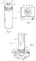
- FIG. 1provides a perspective view of a filling apparatus according to the present invention.
- FIG. 2is an exploded view of the housing of the apparatus depicted in FIG. 1 .
- FIG. 3provides a perspective view of a fluid container that can be used in conjunction with the present invention.
- FIG. 4is an overhead plan view of a base section of the housing depicted in FIG. 2 .
- FIG. 5is a perspective view of the container of FIG. 3 and the base of FIG. 4 connected to one another.
- FIG. 6is a perspective view of a filling apparatus according to the present invention arranged to receive a syringe.
- FIG. 6Ais a cross-sectional view of a port used in the present invention, with the port being in a closed position to prevent the flow of fluid through the port.
- FIG. 7is a perspective view of a syringe being coupled to the filling apparatus of FIG. 6 .
- FIG. 7Ais a cross-sectional of the port of FIG. 6A , with the port being in an open position to allow the flow of fluid through the port.
- FIG. 8is a partial cut-away cross-sectional view of a reservoir of the present filling apparatus containing fluid.
- FIG. 9is a partial cut-away cross-sectional view of the reservoir of FIG. 8 , having less fluid within the reservoir.
- FIG. 10is a perspective view of the present invention, incorporating a heating control switch into the housing of the device.
- FIG. 11is a perspective, partially cut-away, inverted view of the base section, demonstrating the heating system for the present invention.
- FIG. 1depicts a perspective view of a syringe filling apparatus 10 in accordance with the present invention.
- the apparatusgenerally comprises a housing 12 , which comprises a base section 14 and an upright section 16 .
- the upright section 16comprises a backing section 18 and a front section 20 , which enclose a fluid container 22 .
- the base section 14supports a port 24 , which will be discussed in more detail with respect to FIGS. 6-9 .
- the base section 14also supports a signal 26 that will alert a user when the fluid container 22 may need to be replaced. The signal 26 will be described further with respect to FIGS. 8 and 9 .
- FIG. 2provides an exploded view of the housing 12 of the apparatus 10 .
- the backing section 18has a bottom portion 28 that is arranged to slidingly mate with the base section 14 , with base section 14 resting upon the bottom portion 28 .
- the base section 14has a pair of posts 30 that will mate with a pair of slots 32 located on the backing section 18 to secure the base section 14 and the backing section 18 to one another.
- the backing section 18also mates with the front section 20 to form an enclosure for the fluid container 22 .
- the front section 20also has a pair of posts 34 that mates with slots 36 located on the backing section 18 .
- the front section 20could be designed to be pivotally connected to the backing section 18 , to allow for easy opening and closing of the housing 12 , when necessary, to remove or replace the container 22 .
- locks, clasps, or other securing meanscould be used to further close the housing 12 .
- the front section 20 , the backing section 18 , and the base section 14form the housing 12 that provides protection for the container 22 in a manner that is easy to assemble. It is understood that the housing could comprise different arrangements, sizes, or sections, and still fall within the scope of the present invention.
- the fluid container 22has an opening 36 that will be arranged to allow fluid to flow from the container 22 to a reservoir 38 located within the base section 14 , with the container 22 preferably being removably secured to or within the reservoir 38 in a fluid tight arrangement.
- a movable plug 37(shown in phantom) is located within the opening 36 .
- the container 22 and the reservoir 38will be discussed further with respect to FIGS. 3-5 . It should be understood that the reservoir 38 could be designed so that it is may be filled with fluid directly, and it is not necessary to use a container 22 or containers 22 .
- the use of the container 22 coupled or connected to the reservoirminimizes spills and contamination associated with transferring fluid from the container 22 to the reservoir 38 , or from the container 22 directly to a syringe. It is understood that any of these arrangements would fall within the scope of the present invention.
- FIG. 3provides a perspective view of the container 22 used in the present invention, with the container 22 preferably being a standard size used in the industry.
- the opening 36 of the container 22which is also preferably of a typical dimension used within the industry, normally will be sealed prior to use, preferably being hermetically sealed, with a foil-type seal 40 commonly used for sealing containers.
- the container 22has a neck 42 that supports an O-ring 44 , which assists the container 22 in being fluidly connected to the reservoir 38 ( FIGS. 2 and 4 ) in a fluid-tight manner. It should be understood that other sealing means beside the O-ring 44 could be used to provide a seal between the container 22 and the reservoir 38 , such as a press fit or threaded arrangement.
- FIG. 4shows an overhead view of the base section 14 , which houses the reservoir 38 .
- the reservoirhas a perimeter 46 , which is substantially the same size as the opening 36 of the container 22 .
- the base section 14further has an edge 48 that will support the container 22 when the container 22 is mated with the reservoir 38 . If desired, the edge 48 could be of a size that allows the container 22 to be placed inwardly of the edge 48 , thereby providing further support for the container 22 , when the container is in the dispensing position, as shown in FIG. 5 .
- a post 50is located within the reservoir 38 , with the post 50 being designed to pierce the seal 40 located on the opening 36 of the container 22 when the container 22 is mated with the reservoir 38 . The arrangement further minimizes potential spilling or possible contamination of the fluid. It should be understood the shape and design of the reservoir 38 and the base section 14 could be changed and still fall within the scope of the present invention.
- the container 22is shown coupled with the reservoir 38 , which is shown in phantom.
- the opening 36is inserted into the reservoir 38 , with the O-ring 44 being sealingly fit within the perimeter 46 to form a fluid tight arrangement between the container 22 and the reservoir 38 .
- the post 50pierces the seal 40 , thereby allowing fluid to pass from the container 22 into the reservoir 38 in a fluid-tight manner.
- the plug 37(shown in phantom) is pushed out of the opening by the post 50 , and will float upwardly, as the plug 37 is preferably lighter, or less dense, than the fluid within the container 22 .
- fluidcan be transferred from the container 22 to the reservoir 38 without spilling any fluid when opening the container 22 .
- FIGS. 6 and 7demonstrate a syringe 52 being filled from the apparatus 10 .
- the syringe 52mates with the port 24 located on the base section 14 .
- the syringe 52preferably has a LUER-LOK® arrangement, typically known and used in the industry, with a threaded end section 54 that will mate with a threaded section 56 located on the port 24 .
- the syringe 52typically has a fluid passageway 58 that extends outwardly past the threaded end section 54 , which allows the passageway 58 to contact the port 24 prior to the threaded end section 54 contacting the port 24 .
- the port 24has a movable plug 60 , which is normally biased outwardly in a first position when there is no external force on the plug 60 , as shown in FIG. 6A .
- a spring 62 or other similar biasing meanscan be used to keep the plug 60 in a closed position, which will prevent fluid from passing through the port 24 until desired. That is, the arrangement of the port 24 and the plug 60 prevents fluid from flowing through the port 24 until an external device, such as the syringe 52 is attached to or mated with the port 24 .
- the syringe 52is shown coupled or mated with the port 24 .
- the threaded end section 54is threaded onto the threaded section 56 of the port 24 , which cause the passageway 58 to make contact with the plug 60 , thereby inwardly biasing the plug 60 in a second position against the spring 62 , as shown in FIG. 7A .
- Fluidcan then pass through the port 24 , and outwardly into the syringe 52 .
- a plunger 64is pulled backwardly, fluid passes through the passageway 58 and into the syringe 52 .
- the threaded end section 54will be unthreaded from the port 24 .
- the spring 62biases the plug 60 outwardly and seals the port 24 , easily and efficiently, with minimal fluid leakage or loss.
- the plug 60moves easily between an open position that prevents the flow of fluid to a closed position that allows the flow of fluid, without fluid leakage.
- FIGS. 8 and 9provide a cross-sectional view of the apparatus 10 , the container 22 , and the reservoir 38 .
- the reservoir 38is preferably located below the container 22 , so that the container 22 will drain completely into the reservoir 38 .
- a fluid conduit 66connects the reservoir 38 to the port 24 .
- a float 68is located within the reservoir 38 . In FIG. 8 , the float 68 is shown floating within the fluid in the reservoir 38 .
- fluidhas been extracted from the container 22 and the reservoir 38 , thereby allowing the float 68 to move down towards the bottom of the reservoir 38 . When this happens, the alarm 26 will be triggered, thereby telling the user that the container 22 should be replaced and/or the reservoir 38 should be refilled with fluid.
- the alarmis preferably a visual or audible alarm.
- the alarm 26is triggered by the use of a reed switch 70 .
- the reed switch 70is connected in a circuit by wires 72 to the alarm 26 and a power source, such as a standard 9-volt battery 74 .
- a power sourcesuch as a standard 9-volt battery 74 .
- the apparatus 10provides for an efficient system for filling individual syringes from a larger container or reservoir without worrying about spilling the fluid during the transferring process and, also, minimizing contamination of the fluid.
- the apparatus 10provides for an alarm or warning system to notify the operator that the reservoir and/or container are out of fluid.
- the alarm 26will notify the user of fluid depletion before the reservoir 38 is completely empty, thereby preventing any potential disruption in the syringe filling process.
- the apparatus 10 in FIG. 10further includes an on/off switch 90 .
- the switch 90is connected to a heating system, which allows the fluid within the apparatus 10 to be heated prior to filling a syringe 52 ( FIG. 7 ) with fluid. Heating the fluids in the apparatus may allow for increased medicinal reaction rates and increased medicinal antimicrobial activity for the fluids
- a secondary indicator 92may alert the user when the heater system is turned on and heating fluid in the reservoir.
- FIG. 11provides an inverted view of the base section 14 .
- a metal bracket heat sink 94is shown supporting a pair of resistor heaters 96 , which forms a portion of the heating system.
- the resistors 96are connected in parallel. In simplistic terms, by applying an electrical current between wires 98 and 102 , the resistors heat up and provide heat energy to the metal bracket heat sink 94 , which in turn hearts up the solution reservoir 38 .
- a temperature switches 108 and fuse holder 104are added in series with the positive power supply wire lead 106 .
- the switch 90When the switch 90 is turned on, an electrical current goes through the wire 106 , fuse holder 104 , temperature switch 108 , input terminal 112 , through temperature switch 108 , output terminal 110 , and into heater resistors 96 .
- the heater resistors 98continue to heat up until a set temperature point is reached at which time the temperature switch 108 opens the electric circuit connections at input terminal 112 and output terminal 110 , stopping the heating process.
- the temperature switch 108senses the temperature reduction and therefore closes the electrical circuit, starting the heating process all over again. By automatically switching on and off the temperature, the switch 108 maintains a predetermined temperature set point.
- the fuse holder 104has an internal fuse, not shown, to protect the electronic heating circuit.
- the switch 108will pass energy, i.e. heat, to the bracket 94 , which in turn will pass heat to the reservoir 38 , thereby heating the fluid within the reservoir.
- the energy passing through the systempreferably is sufficient enough to heat the fluid within the reservoir 38 , but will not damage the reservoir 38 , which is preferably designed from a plastic or thermoplastic material.
- the resistor heaters 96are connected in parallel, but series arrangements or more or fewer resistors are possible. In one arrangement, the two resistors are both 10 ohm ( ⁇ ) resistors arranged in parallel.
Landscapes
- Health & Medical Sciences (AREA)
- Pharmacology & Pharmacy (AREA)
- Life Sciences & Earth Sciences (AREA)
- Animal Behavior & Ethology (AREA)
- General Health & Medical Sciences (AREA)
- Public Health (AREA)
- Veterinary Medicine (AREA)
- Infusion, Injection, And Reservoir Apparatuses (AREA)
Abstract
Description
Claims (8)
Priority Applications (1)
| Application Number | Priority Date | Filing Date | Title |
|---|---|---|---|
| US12/387,195US8671994B2 (en) | 2008-09-05 | 2009-04-29 | Syringe filling apparatus |
Applications Claiming Priority (2)
| Application Number | Priority Date | Filing Date | Title |
|---|---|---|---|
| US12/231,790US20100059139A1 (en) | 2008-09-05 | 2008-09-05 | Syringe filling apparatus |
| US12/387,195US8671994B2 (en) | 2008-09-05 | 2009-04-29 | Syringe filling apparatus |
Related Parent Applications (1)
| Application Number | Title | Priority Date | Filing Date |
|---|---|---|---|
| US12/231,790Continuation-In-PartUS20100059139A1 (en) | 2008-09-05 | 2008-09-05 | Syringe filling apparatus |
Publications (2)
| Publication Number | Publication Date |
|---|---|
| US20100059140A1 US20100059140A1 (en) | 2010-03-11 |
| US8671994B2true US8671994B2 (en) | 2014-03-18 |
Family
ID=41798183
Family Applications (1)
| Application Number | Title | Priority Date | Filing Date |
|---|---|---|---|
| US12/387,195Active2028-09-21US8671994B2 (en) | 2008-09-05 | 2009-04-29 | Syringe filling apparatus |
Country Status (1)
| Country | Link |
|---|---|
| US (1) | US8671994B2 (en) |
Cited By (5)
| Publication number | Priority date | Publication date | Assignee | Title |
|---|---|---|---|---|
| US20120204996A1 (en)* | 2006-02-09 | 2012-08-16 | Deka Products Limited Partnership | Adhesive and Peripheral Systems and Methods for Medical Devices |
| DE202015001771U1 (en) | 2015-03-06 | 2016-06-09 | Coltène/Whaledent GmbH + Co. KG | Extraction device for liquids |
| WO2016142215A1 (en) | 2015-03-06 | 2016-09-15 | Coltène/Whaledent Gmbh & Co. Kg | Fluid extraction device |
| USD799027S1 (en) | 2016-01-28 | 2017-10-03 | Coltene/Whaledent Gmbh & Co. Kg | Modular filling station for filling syringes |
| USD799693S1 (en) | 2016-01-28 | 2017-10-10 | Coltene/Whaledent Gmbh & Co. Kg | Bottle holder for a modular filling station for filling syringes |
Families Citing this family (1)
| Publication number | Priority date | Publication date | Assignee | Title |
|---|---|---|---|---|
| US8286671B1 (en) | 2011-03-23 | 2012-10-16 | Saverio Roberto Strangis | Automated syringe filler and loading apparatus |
Citations (9)
| Publication number | Priority date | Publication date | Assignee | Title |
|---|---|---|---|---|
| US4253501A (en)* | 1979-11-09 | 1981-03-03 | Ims Limited | Transfer system |
| US4312349A (en)* | 1979-07-23 | 1982-01-26 | Cohen Milton J | Filter device for injectable fluid |
| US5222530A (en)* | 1988-10-14 | 1993-06-29 | Elkay Manufacturing Company | Hygienic cap and liquid dispensing system |
| US5566729A (en)* | 1995-04-06 | 1996-10-22 | Abbott Laboratories | Drug reconstitution and administration system |
| US6425420B2 (en)* | 2000-04-07 | 2002-07-30 | Degussa Ag | Procedure device for the decanting of dental filling substances |
| US20040154690A1 (en)* | 2002-12-03 | 2004-08-12 | Osborne Joel A. | Automated apparatus and process for reconstitution and delivery of medication to an automated syringe preparation apparatus |
| US6820662B2 (en)* | 2001-12-20 | 2004-11-23 | Original Ideas | Vertical bubble dispensing device |
| US20060025747A1 (en)* | 2004-07-29 | 2006-02-02 | Sullivan Roy H | Vial adaptor |
| US7418981B2 (en)* | 2004-09-02 | 2008-09-02 | Baker James W | System for dispensing biological fluids |
- 2009
- 2009-04-29USUS12/387,195patent/US8671994B2/enactiveActive
Patent Citations (9)
| Publication number | Priority date | Publication date | Assignee | Title |
|---|---|---|---|---|
| US4312349A (en)* | 1979-07-23 | 1982-01-26 | Cohen Milton J | Filter device for injectable fluid |
| US4253501A (en)* | 1979-11-09 | 1981-03-03 | Ims Limited | Transfer system |
| US5222530A (en)* | 1988-10-14 | 1993-06-29 | Elkay Manufacturing Company | Hygienic cap and liquid dispensing system |
| US5566729A (en)* | 1995-04-06 | 1996-10-22 | Abbott Laboratories | Drug reconstitution and administration system |
| US6425420B2 (en)* | 2000-04-07 | 2002-07-30 | Degussa Ag | Procedure device for the decanting of dental filling substances |
| US6820662B2 (en)* | 2001-12-20 | 2004-11-23 | Original Ideas | Vertical bubble dispensing device |
| US20040154690A1 (en)* | 2002-12-03 | 2004-08-12 | Osborne Joel A. | Automated apparatus and process for reconstitution and delivery of medication to an automated syringe preparation apparatus |
| US20060025747A1 (en)* | 2004-07-29 | 2006-02-02 | Sullivan Roy H | Vial adaptor |
| US7418981B2 (en)* | 2004-09-02 | 2008-09-02 | Baker James W | System for dispensing biological fluids |
Cited By (6)
| Publication number | Priority date | Publication date | Assignee | Title |
|---|---|---|---|---|
| US20120204996A1 (en)* | 2006-02-09 | 2012-08-16 | Deka Products Limited Partnership | Adhesive and Peripheral Systems and Methods for Medical Devices |
| US9931479B2 (en)* | 2006-02-09 | 2018-04-03 | Deka Products Limited Partnership | Peripheral systems and methods for medical devices |
| DE202015001771U1 (en) | 2015-03-06 | 2016-06-09 | Coltène/Whaledent GmbH + Co. KG | Extraction device for liquids |
| WO2016142215A1 (en) | 2015-03-06 | 2016-09-15 | Coltène/Whaledent Gmbh & Co. Kg | Fluid extraction device |
| USD799027S1 (en) | 2016-01-28 | 2017-10-03 | Coltene/Whaledent Gmbh & Co. Kg | Modular filling station for filling syringes |
| USD799693S1 (en) | 2016-01-28 | 2017-10-10 | Coltene/Whaledent Gmbh & Co. Kg | Bottle holder for a modular filling station for filling syringes |
Also Published As
| Publication number | Publication date |
|---|---|
| US20100059140A1 (en) | 2010-03-11 |
Similar Documents
| Publication | Publication Date | Title |
|---|---|---|
| US8671994B2 (en) | Syringe filling apparatus | |
| US9814345B2 (en) | Baby formula preparation with warming system and customized pods | |
| US4563175A (en) | Multiple syringe pump | |
| JPH05507014A (en) | Irrigation device and method for delivering a predetermined one of a plurality of solutions to a treatment area | |
| PT94017A (en) | BOMBING DEVICE FOR BIOMEDICAL USE | |
| WO2011015912A1 (en) | Thermostatting device for containers of bio-medical fluids for parenteral administration, particularly bags for medical fluids, blood or the like | |
| US20100225494A1 (en) | Fluid Flow Outage Safety and Warning Device | |
| EP1579762B1 (en) | Disposable, active substance-releasing electrical device | |
| AU733213B2 (en) | Compact liquid dosing apparatus with a reservoir | |
| JPH04500622A (en) | Syringes for dispensing different types of liquid therapeutics | |
| EP2268341B1 (en) | Antegrade colonic instillation apparatus | |
| EA010516B1 (en) | Liquid blocking apparatus and system equipped with an alarm or wireless calling device and a storing bag | |
| KR102765769B1 (en) | System for dispensing and heating liquid | |
| US20100059139A1 (en) | Syringe filling apparatus | |
| KR20130013407A (en) | An apparatus with heating means for food and drink | |
| CN108159443B (en) | Steam sterilization cabinet and control method thereof | |
| CN114366653A (en) | Household medicine packaging and storage integrated device | |
| US4707343A (en) | Apparatus for sterilizing contact lenses | |
| GB2074545A (en) | Liquid dispensing apparatus | |
| HK1131317A (en) | Disposable electrical device for releasing active substances | |
| HK1081398B (en) | Disposable, active substance-releasing electrical device | |
| KR20250092178A (en) | Filling device and method for filling a reusable reservoir of a medical dispensing device | |
| HU185962B (en) | Fluid feeding device of contactless operation particularly for sanitary purposes | |
| HK40041246A (en) | System for administering and heating liquids | |
| CN114532849A (en) | Water drinking equipment |
Legal Events
| Date | Code | Title | Description |
|---|---|---|---|
| AS | Assignment | Owner name:INTER-MED, INC.,WISCONSIN Free format text:ASSIGNMENT OF ASSIGNORS INTEREST;ASSIGNORS:POND, GARY J.;COTIC, DENNIS;REEL/FRAME:022858/0360 Effective date:20090605 Owner name:INTER-MED, INC., WISCONSIN Free format text:ASSIGNMENT OF ASSIGNORS INTEREST;ASSIGNORS:POND, GARY J.;COTIC, DENNIS;REEL/FRAME:022858/0360 Effective date:20090605 | |
| AS | Assignment | Owner name:SECURANT BANK & TRUST, WISCONSIN Free format text:SECURITY AGREEMENT;ASSIGNOR:INTER-MED, INC.;REEL/FRAME:028942/0436 Effective date:20090302 | |
| STCF | Information on status: patent grant | Free format text:PATENTED CASE | |
| AS | Assignment | Owner name:INTER-MED INC., WISCONSIN Free format text:RELEASE BY SECURED PARTY;ASSIGNOR:SECURANT BANK & TRUST;REEL/FRAME:036784/0610 Effective date:20120912 | |
| AS | Assignment | Owner name:WISCONSIN BANK & TRUST, WISCONSIN Free format text:SECURITY INTEREST;ASSIGNORS:INTER-MED, INC.;POND, GARY J.;REEL/FRAME:036975/0600 Effective date:20151029 | |
| MAFP | Maintenance fee payment | Free format text:PAYMENT OF MAINTENANCE FEE, 4TH YR, SMALL ENTITY (ORIGINAL EVENT CODE: M2551) Year of fee payment:4 | |
| AS | Assignment | Owner name:AVANTE MEZZANINE PARTNERS SBIC II, L.P., CALIFORNI Free format text:SECURITY INTEREST;ASSIGNOR:INTER-MED, INC.;REEL/FRAME:046253/0147 Effective date:20180628 | |
| AS | Assignment | Owner name:INTER-MED, INC., WISCONSIN Free format text:RELEASE BY SECURED PARTY;ASSIGNOR:WISCONSIN BANK & TRUST;REEL/FRAME:046505/0861 Effective date:20180618 | |
| MAFP | Maintenance fee payment | Free format text:PAYMENT OF MAINTENANCE FEE, 8TH YR, SMALL ENTITY (ORIGINAL EVENT CODE: M2552); ENTITY STATUS OF PATENT OWNER: SMALL ENTITY Year of fee payment:8 | |
| AS | Assignment | Owner name:MARANON CAPITAL, L.P., AS ADMINISTRATIVE AGENT, ILLINOIS Free format text:SECURITY INTEREST;ASSIGNORS:INTER-MED, INC.;APEX DENTAL MATERIALS, LLC;REEL/FRAME:059530/0599 Effective date:20220407 | |
| AS | Assignment | Owner name:INTER-MED, INC., WISCONSIN Free format text:RELEASE BY SECURED PARTY;ASSIGNOR:AVANTE MEZZANINE PARTNERS SBIC II, L.P.;REEL/FRAME:059558/0004 Effective date:20220407 | |
| AS | Assignment | Owner name:BMO BANK N.A., AS ADMINISTRATIVE AGENT, ILLINOIS Free format text:SECURITY INTEREST;ASSIGNOR:INTER-MED, INC.;REEL/FRAME:066993/0755 Effective date:20240403 | |
| AS | Assignment | Owner name:APEX DENTAL MATERIALS, LLC, WISCONSIN Free format text:SECURITY INTEREST;ASSIGNOR:MARANON CAPITAL, L.P., AS AGENT;REEL/FRAME:067010/0306 Effective date:20240403 Owner name:INTER-MED, INC., WISCONSIN Free format text:SECURITY INTEREST;ASSIGNOR:MARANON CAPITAL, L.P., AS AGENT;REEL/FRAME:067010/0306 Effective date:20240403 | |
| AS | Assignment | Owner name:APEX DENTAL MATERIALS, LLC, WISCONSIN Free format text:CORRECTIVE ASSIGNMENT TO CORRECT THE NATURE OF CONVEYANCE PREVIOUSLY RECORDED ON REEL 67010 FRAME 306. ASSIGNOR(S) HEREBY CONFIRMS THE RELEASE OF SECURITY INTEREST;ASSIGNOR:MARANON CAPITAL, L.P., AS AGENT;REEL/FRAME:067029/0280 Effective date:20240403 Owner name:INTER-MED, INC., WISCONSIN Free format text:CORRECTIVE ASSIGNMENT TO CORRECT THE NATURE OF CONVEYANCE PREVIOUSLY RECORDED ON REEL 67010 FRAME 306. ASSIGNOR(S) HEREBY CONFIRMS THE RELEASE OF SECURITY INTEREST;ASSIGNOR:MARANON CAPITAL, L.P., AS AGENT;REEL/FRAME:067029/0280 Effective date:20240403 Owner name:APEX DENTAL MATERIALS, LLC, WISCONSIN Free format text:CORRECTIVE ASSIGNMENT TO CORRECT THE NATURE OF CONVEYANCE TO RELEASE OF SECURITY INTEREST PREVIOUSLY RECORDED ON REEL 67010 FRAME 306. ASSIGNOR(S) HEREBY CONFIRMS THE RELEASE OF SECURITY INTEREST;ASSIGNOR:MARANON CAPITAL, L.P., AS AGENT;REEL/FRAME:067028/0628 Effective date:20240403 Owner name:INTER-MED, INC., WISCONSIN Free format text:CORRECTIVE ASSIGNMENT TO CORRECT THE NATURE OF CONVEYANCE TO RELEASE OF SECURITY INTEREST PREVIOUSLY RECORDED ON REEL 67010 FRAME 306. ASSIGNOR(S) HEREBY CONFIRMS THE RELEASE OF SECURITY INTEREST;ASSIGNOR:MARANON CAPITAL, L.P., AS AGENT;REEL/FRAME:067028/0628 Effective date:20240403 |