US8671743B2 - Test equipment manifold interface - Google Patents
Test equipment manifold interfaceDownload PDFInfo
- Publication number
- US8671743B2 US8671743B2US13/488,452US201213488452AUS8671743B2US 8671743 B2US8671743 B2US 8671743B2US 201213488452 AUS201213488452 AUS 201213488452AUS 8671743 B2US8671743 B2US 8671743B2
- Authority
- US
- United States
- Prior art keywords
- dtm
- manifold
- interface
- test equipment
- hollow piston
- Prior art date
- Legal status (The legal status is an assumption and is not a legal conclusion. Google has not performed a legal analysis and makes no representation as to the accuracy of the status listed.)
- Expired - Fee Related, expires
Links
Images


Classifications
- G—PHYSICS
- G01—MEASURING; TESTING
- G01M—TESTING STATIC OR DYNAMIC BALANCE OF MACHINES OR STRUCTURES; TESTING OF STRUCTURES OR APPARATUS, NOT OTHERWISE PROVIDED FOR
- G01M15/00—Testing of engines
- G01M15/04—Testing internal-combustion engines
- G01M15/042—Testing internal-combustion engines by monitoring a single specific parameter not covered by groups G01M15/06 - G01M15/12
- G01M15/048—Testing internal-combustion engines by monitoring a single specific parameter not covered by groups G01M15/06 - G01M15/12 by monitoring temperature
- G—PHYSICS
- G01—MEASURING; TESTING
- G01M—TESTING STATIC OR DYNAMIC BALANCE OF MACHINES OR STRUCTURES; TESTING OF STRUCTURES OR APPARATUS, NOT OTHERWISE PROVIDED FOR
- G01M15/00—Testing of engines
- G01M15/02—Details or accessories of testing apparatus
- G—PHYSICS
- G01—MEASURING; TESTING
- G01R—MEASURING ELECTRIC VARIABLES; MEASURING MAGNETIC VARIABLES
- G01R31/00—Arrangements for testing electric properties; Arrangements for locating electric faults; Arrangements for electrical testing characterised by what is being tested not provided for elsewhere
- G01R31/28—Testing of electronic circuits, e.g. by signal tracer
- G01R31/2851—Testing of integrated circuits [IC]
- G01R31/2855—Environmental, reliability or burn-in testing
- G01R31/2872—Environmental, reliability or burn-in testing related to electrical or environmental aspects, e.g. temperature, humidity, vibration, nuclear radiation
- G01R31/2874—Environmental, reliability or burn-in testing related to electrical or environmental aspects, e.g. temperature, humidity, vibration, nuclear radiation related to temperature
Definitions
- the present inventionrelates to integrated circuit (IC) test equipment and, more particularly, to a manifold interface for IC test equipment.
- ICintegrated circuit
- a load boardis often used when testing an electronic device (device under test or DUT) such as packaged semiconductor chip or integrated circuit.
- the load boardis essentially an interface board, similar to a circuit board, which provides an interface between test equipment (automatic test equipment or ATE) and the device or DUT.
- thermal testingWhen testing certain devices, thermal testing must be performed to determine if the DUT meets specific requirements or standards. During thermal testing, the DUT is subjected to varying temperatures to determine whether it can operate in varied ambient conditions.
- DTMDevice Under Test Thermal Management
- the DUTis mounted to a load board that has a manifold. The manifold engages with a manifold of the ATE and to accurately direct temperature controlled air at the DUT. This controlled air is typically directed to leads of each DUT that is mounted on the load board and allows for testing of each DUT when heated to a temperature associated with its temperature rating.
- DTM testingis suitable for devices that are subject to temperature extremes such as devices used near an engine of an automobile and therefore the directed air is often at temperatures of over 100° C.
- non-DTM testingmay be performed.
- the load boarddoes not have a manifold since heated temperature controlled air does not need to be accurately directed at the DUT.
- test equipmentis often required to perform both DTM and Non-DTM testing, the interface between the load-board and test equipment must be replaced when changing between DTM and non-DTM testing. This interface replacement can be a time consuming and costly exercise, resulting in unwanted test equipment down-time. Accordingly, it would be advantageous to be have an ATE with a manifold that can be readily replaced, changed, or interfaced with other devices or equipment.
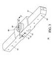
- FIG. 1is an exploded perspective view of a test equipment manifold interface viewed from a first side in accordance with a preferred embodiment of the present invention
- FIG. 2is an exploded perspective view of the test equipment manifold interface of FIG. 1 when viewed from an opposite second side.
- FIG. 3is an assembled perspective view of the test equipment manifold interface of FIG. 1 viewed from view the first side;
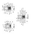
- FIG. 4is a cross-sectional view, through 3 - 3 ′ of FIG. 3 , with a hollow piston in a retracted position;
- FIG. 5is cross-sectional view, through 3 - 3 ′ of FIG. 3 , when the hollow piston is in an extended or protruding position.
- FIG. 6is a cross-sectional view, through 5 - 5 ′ of FIG. 5 ;
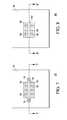
- FIG. 7is a front plan view of a DTM load board
- FIG. 8is a front plan view of a non-DTM load board
- FIG. 9is a cross-sectional of a test equipment assembly including an inverted view through 7 - 7 ′ of the DTM load board of FIG. 7 in accordance with an embodiment of the present invention.
- FIG. 10is a cross-sectional of the test equipment assembly of FIG. 9 including an inverted view through 8 - 8 ′ of the non-DTM load board of FIG. 8 in accordance with an embodiment of the present invention.
- the present inventionprovides for a test equipment manifold interface comprising a housing, an air inlet aperture in the housing and a plurality of outlet apertures in the housing.
- a test equipment manifold interfacecomprising a housing, an air inlet aperture in the housing and a plurality of outlet apertures in the housing.
- the chamberhas a chamber inlet provided by the air inlet aperture and a chamber outlet coupled to the plurality of outlet apertures.
- a hollow pistonis captive in the chamber.
- the hollow pistonhas a DTM interface outlet aperture and a DTM interface inlet aperture.
- the hollow pistondirects air to flow from the air inlet aperture to the DTM interface outlet aperture.
- the hollow pistondirects air to flow from the air inlet to the plurality of outlet apertures via the chamber outlet.
- the present inventionprovides for a test equipment assembly comprising a test equipment mount with at least one mount air outlet aperture.
- the manifold interfaceincludes a housing, an air inlet aperture in the housing and a plurality of outlet apertures in the housing.
- a hollow pistonis captive in the chamber.
- the hollow pistonhas a DTM interface outlet aperture and a DTM interface inlet aperture.
- the air inlet apertureis operatively coupled to the mount air outlet aperture and in operation the hollow piston provides for selectively directing air from the air inlet aperture to either the DTM interface outlet aperture or the plurality of apertures.
- FIG. 1an exploded perspective view of a test equipment manifold interface 100 viewed from a first side in accordance with a preferred embodiment of the present invention is shown.
- the test equipment manifold interface 100has a housing 101 and there is an air inlet aperture 102 in the housing 101 .
- the chamber 104has a chamber inlet 105 provided by an orifice of the air inlet aperture 102 and a chamber outlet 106 is coupled to the plurality of outlet apertures 103 .
- a compression spring 111 of a size (diameter)is provided that can be accommodated in the chamber 104 .
- a retainer screw 112operative couples with a threaded hole 113 in the housing 101 and the hollow piston 107 has a slot 114 for accommodating an end of the retainer screw 112 .
- FIG. 2is an exploded perspective view of the test equipment manifold interface 100 when viewed from an opposite second side.
- the hollow piston 107has a DTM interface outlet aperture 201 and a DTM interface inlet aperture 202 operatively coupled together by a piston passage 210 in the hollow piston 107 .
- the DTM interface outlet aperture 201is in the manifold abutting end 108 of the hollow piston 107 and the DTM interface inlet aperture 202 is in a side wall of the hollow piston 107 .
- There is also a notch 211 in the hollow piston 107and the notch 211 is aligned with the DTM interface inlet aperture 202 along the axial length L-L′ of the hollow piston 107 .
- guide pin apertures 203for assisting in mounting and dismounting of the test equipment manifold interface 100 to a test equipment mount and there is also an interface socket 212 in the housing 101 .
- FIG. 3is an assembled perspective view of the test equipment manifold interface 100 viewed from view the first side.
- the hollow piston 107is held captive in the chamber 104 by the retainer screw 112 engaging the slot 114 , and the manifold abutting end 108 of the hollow piston 107 is in an extended position protruding out of the housing 101 at its maximum extended position allowed by the retainer screw 112 and slot 114 .
- FIG. 4is a cross-sectional view, through 3 - 3 ′ of FIG. 3 , of the test equipment manifold interface 100 when the hollow piston 107 is in a retracted position.
- the compression spring 111is located at a blank end of the chamber 104 which provides a biasing of the hollow piston 107 to an extended or protruding position.
- the hollow piston 107is located in a retracted position due to a force, illustrated by an arrow F, applied to gasket 109 in which the force overcomes the biasing of the compression spring 111 .
- the DTM interface inlet aperture 202is aligned with the chamber inlet 105 and thus air from the air inlet aperture 102 can pass through the DTM interface inlet aperture 202 , through the piston passage 210 in the hollow piston 107 and out of the DTM interface outlet aperture 201 .
- the flow of air supplied from the inlet aperture 102is illustrated by an arrow A.
- the chamber outlet 106is an area proximal to at least one feeder passage 410 in the housing 101 , wherein the feeder passage 410 is operatively coupled to the outlet apertures 103 . More specifically, the chamber outlet 106 is area proximal to the feeder passage 410 and includes an orifice 411 of the feeder passage 410 .
- FIG. 5another cross-sectional view, through 3 - 3 ′ of FIG. 3 , of the test equipment manifold interface 100 when the hollow piston 107 is in an extended or protruding position is shown.
- the hollow piston 107is in the extended or protruding position because there is no counteracting force overcoming the biasing of the compression spring 111 .
- the DTM interface inlet aperture 202is misaligned with the chamber inlet 105 and therefore air cannot flow from the air inlet aperture 102 , through the piston passage 210 and out of the DTM interface outlet aperture 201 .
- the notch 211is aligned with the chamber inlet 105 and thus air from the air inlet aperture 102 is directed into the chamber outlet 106 along at least one feeder passage 410 and to the outlet apertures 103 .
- the flow of air supplied from the inlet aperture 102when the hollow piston 107 is in the extended or protruding position, is illustrated by an arrow B.
- the hollow piston 107is biased by the compression spring 111 to direct air to the outlet apertures 103 .
- FIG. 6there is illustrated a cross sectional view, through 5 - 5 ′ of FIG. 5 , of the test equipment manifold interface 100 .
- This illustrationshows the relationship of the feeder passage 410 to the chamber 104 and outlet apertures 103 .
- FIG. 7is a front plan view of a DTM load board 700 comprising a circuit board 701 to which are mounted test sockets 702 and a DTM load board manifold 703 .
- This particular manifold 703has two DTM manifold inlet apertures 704 at either end of the manifold 703 .
- the manifold 703has passages in communication with passages in the test sockets 702 . Therefore, in operation hot air can flow through the DTM manifold inlet apertures 704 , into the manifold passages, through the passages in test sockets 702 to thereby heat pins of each device under test (not shown) seated in the test sockets 702 .
- Other features of the load boardsuch as and external coupling are not shown as will be apparent to a person skilled in the art.
- FIG. 8is a front plan view of a non-DTM load board 800 comprising a circuit board 801 to which are mounted test sockets 802 and a non-DTM load board manifold 803 .
- This particular manifold 803is a blank or dummy manifold and it is shorter than the DTM manifold 703 and does not have any DTM manifold inlet apertures 704 at either end of the manifold 803 .
- Other features of the load boardsuch as and external coupling are not shown as will be apparent to a person skilled in the art.
- FIG. 9there is illustrated a cross sectional view of a test equipment assembly 900 including an inverted view through 7 - 7 ′ of the DTM load board 700 in accordance with an embodiment of the present invention.
- the test equipment assembly 900has a test equipment mount 901 with mount air outlet apertures 902 and associated interface engagement spigots 903 .
- the test equipment mount 901also has clamps (not shown) for attachment of load boards.
- There are two test equipment manifold interfaces 100 attached to the test equipment mount 901the two test equipment manifold interfaces 100 are bolted to the test equipment mount 901 and the engagement spigots 903 engage the interface sockets 212 .
- the DTM load board 700 with a DTM load board manifold 203is clamped to the test equipment mount 901 and thereby the DTM load board manifold 703 engages the test equipment manifold interfaces 100 .
- the DTM load board manifold 703actuates the hollow piston 107 thereby directing air to flow from the air inlet aperture 102 to the DTM interface outlet aperture 201 and into the DTM load board manifold 703 . More specifically, because the DTM load board manifold 703 engages the manifold interface 100 the manifold abutting end 108 engages the DTM load board manifold 203 .
- the hollow pistonis directing hot air from the mount air outlet apertures 902 to flow from the air inlet apertures 102 to the DTM interface outlet apertures and therefore the DTM interface inlet aperture 202 is aligned with the chamber inlet 105 .
- FIG. 10is a cross-sectional of the test equipment assembly 900 including an inverted view through 8 - 8 ′ of the non-DTM load board 800 in accordance with an embodiment of the present invention.
- the non-DTM load board 800 withis clamped to the test equipment mount 901 , however, the non-DTM load board manifold 803 (dummy manifold) does not engage the test equipment manifold interfaces 100 .
- the compression spring 111urges the hollow pistons 107 to the protruded position and thus the hollow pistons 107 direct air to flow from the air inlet apertures 102 to the outlet apertures 103 and this occurs in this embodiment when the notch 211 is aligned with the chamber inlet 105 .
- the present inventionoperates such that when the air inlet aperture 102 is operatively coupled to the mount air outlet aperture 902 , the hollow piston 107 provides for selectively directing air from the air inlet aperture 102 to either the DTM interface outlet aperture 201 or the plurality of apertures 103 .
- the present inventionprovides for a single test equipment manifold interface that can be used for both DTM testing and non-DTM testing.
Landscapes
- Physics & Mathematics (AREA)
- General Physics & Mathematics (AREA)
- Chemical & Material Sciences (AREA)
- Engineering & Computer Science (AREA)
- Combustion & Propulsion (AREA)
- Investigating Strength Of Materials By Application Of Mechanical Stress (AREA)
- Testing Of Individual Semiconductor Devices (AREA)
Abstract
Description
Claims (20)
Priority Applications (1)
| Application Number | Priority Date | Filing Date | Title |
|---|---|---|---|
| US13/488,452US8671743B2 (en) | 2012-06-05 | 2012-06-05 | Test equipment manifold interface |
Applications Claiming Priority (1)
| Application Number | Priority Date | Filing Date | Title |
|---|---|---|---|
| US13/488,452US8671743B2 (en) | 2012-06-05 | 2012-06-05 | Test equipment manifold interface |
Publications (2)
| Publication Number | Publication Date |
|---|---|
| US20130319098A1 US20130319098A1 (en) | 2013-12-05 |
| US8671743B2true US8671743B2 (en) | 2014-03-18 |
Family
ID=49668628
Family Applications (1)
| Application Number | Title | Priority Date | Filing Date |
|---|---|---|---|
| US13/488,452Expired - Fee RelatedUS8671743B2 (en) | 2012-06-05 | 2012-06-05 | Test equipment manifold interface |
Country Status (1)
| Country | Link |
|---|---|
| US (1) | US8671743B2 (en) |
Citations (5)
| Publication number | Priority date | Publication date | Assignee | Title |
|---|---|---|---|---|
| US3776599A (en) | 1966-01-03 | 1973-12-04 | Cons Eng Co | Self-purging, pneumatic conveying apparatus including fluid flow pumps on scales, with agitator, vacuum filled, with material dryer, and of varied means of sequential value operation |
| US5254310A (en) | 1990-12-31 | 1993-10-19 | Gaz De France | High temperature generalized corrosion test installation |
| US20040035191A1 (en)* | 2002-04-24 | 2004-02-26 | Sternberger Waynle I. | Sampling interface for a vehicle |
| US20080267790A1 (en) | 1993-07-16 | 2008-10-30 | Gaudet Peter W | Electronically Controlled Vacuum Pump |
| US7487683B2 (en) | 2005-03-31 | 2009-02-10 | Denso Corporation | Endurance testing apparatus |
- 2012
- 2012-06-05USUS13/488,452patent/US8671743B2/ennot_activeExpired - Fee Related
Patent Citations (6)
| Publication number | Priority date | Publication date | Assignee | Title |
|---|---|---|---|---|
| US3776599A (en) | 1966-01-03 | 1973-12-04 | Cons Eng Co | Self-purging, pneumatic conveying apparatus including fluid flow pumps on scales, with agitator, vacuum filled, with material dryer, and of varied means of sequential value operation |
| US5254310A (en) | 1990-12-31 | 1993-10-19 | Gaz De France | High temperature generalized corrosion test installation |
| US20080267790A1 (en) | 1993-07-16 | 2008-10-30 | Gaudet Peter W | Electronically Controlled Vacuum Pump |
| US20040035191A1 (en)* | 2002-04-24 | 2004-02-26 | Sternberger Waynle I. | Sampling interface for a vehicle |
| US6837121B2 (en)* | 2002-04-24 | 2005-01-04 | The Johns Hopkins University | Sampling interface for a vehicle |
| US7487683B2 (en) | 2005-03-31 | 2009-02-10 | Denso Corporation | Endurance testing apparatus |
Also Published As
| Publication number | Publication date |
|---|---|
| US20130319098A1 (en) | 2013-12-05 |
Similar Documents
| Publication | Publication Date | Title |
|---|---|---|
| US8704542B2 (en) | Thermal chamber for IC chip testing | |
| US9354138B2 (en) | Fixture for test circuit board reliability testing | |
| KR101214033B1 (en) | Test apparatus and connecting apparatus | |
| US7042240B2 (en) | Burn-in testing apparatus and method | |
| US11448694B2 (en) | Semiconductor package test apparatus | |
| US20160021789A1 (en) | Electronic control apparatus and method for connecting substrate of electronic control apparatus | |
| CA2557600A1 (en) | Burn-in testing apparatus and method | |
| JPWO2008090754A1 (en) | Motor control device | |
| US9125305B2 (en) | Devices with pneumatic, hydraulic and electrical components | |
| US9293857B2 (en) | Sealed and un-mated electrical connection system using single insertion press fit pins | |
| US6703852B1 (en) | Low-temperature semiconductor device testing apparatus with purge box | |
| US8671743B2 (en) | Test equipment manifold interface | |
| US6549025B1 (en) | System and method for thermal testing of circuit boards using thermal films | |
| US20150253160A1 (en) | Flexible chassis interface device | |
| KR101997847B1 (en) | Interface board for testing semiconductor device using coolant | |
| US6692267B1 (en) | Printed circuit board testing module | |
| KR102015395B1 (en) | Interface board for testing semiconductor device | |
| US8081481B2 (en) | Apparatus and method for a clip device for coupling a heat sink plate system with a burn-in board system | |
| US20130141868A1 (en) | Thermally controlled assembly | |
| KR20140141405A (en) | Test handler | |
| US8063646B2 (en) | Apparatus and methods for testing microelectronic devices | |
| US11821842B2 (en) | Heatsink with visual installation indicator | |
| US6859056B2 (en) | Test fixture for semiconductor package and test method of using the same | |
| US5686833A (en) | Load board enhanced for differential pressure retention in an IC test head | |
| US20110269320A1 (en) | Means for securing a power supply to a bus bar |
Legal Events
| Date | Code | Title | Description |
|---|---|---|---|
| AS | Assignment | Owner name:FREESCALE SEMICONDUCTOR, INC., TEXAS Free format text:ASSIGNMENT OF ASSIGNORS INTEREST;ASSIGNORS:SINGH, BHARATHI RANJIT;RASHID, AZMI;SANTHINAN, KATHIRAWAN;REEL/FRAME:028314/0556 Effective date:20120516 | |
| AS | Assignment | Owner name:CITIBANK, N.A., AS COLLATERAL AGENT, NEW YORK Free format text:SUPPLEMENT TO IP SECURITY AGREEMENT;ASSIGNOR:FREESCALE SEMICONDUCTOR, INC.;REEL/FRAME:030256/0706 Effective date:20120724 | |
| AS | Assignment | Owner name:CITIBANK, N.A., AS NOTES COLLATERAL AGENT, NEW YOR Free format text:SUPPLEMENT TO IP SECURITY AGREEMENT;ASSIGNOR:FREESCALE SEMICONDUCTOR, INC.;REEL/FRAME:030258/0501 Effective date:20120724 Owner name:CITIBANK, N.A., AS NOTES COLLATERAL AGENT, NEW YOR Free format text:SUPPLEMENT TO IP SECURITY AGREEMENT;ASSIGNOR:FREESCALE SEMICONDUCTOR, INC.;REEL/FRAME:030258/0479 Effective date:20120724 | |
| AS | Assignment | Owner name:CITIBANK, N.A., AS NOTES COLLATERAL AGENT, NEW YORK Free format text:SECURITY AGREEMENT;ASSIGNOR:FREESCALE SEMICONDUCTOR, INC.;REEL/FRAME:030633/0424 Effective date:20130521 Owner name:CITIBANK, N.A., AS NOTES COLLATERAL AGENT, NEW YOR Free format text:SECURITY AGREEMENT;ASSIGNOR:FREESCALE SEMICONDUCTOR, INC.;REEL/FRAME:030633/0424 Effective date:20130521 | |
| AS | Assignment | Owner name:CITIBANK, N.A., AS NOTES COLLATERAL AGENT, NEW YORK Free format text:SECURITY AGREEMENT;ASSIGNOR:FREESCALE SEMICONDUCTOR, INC.;REEL/FRAME:031591/0266 Effective date:20131101 Owner name:CITIBANK, N.A., AS NOTES COLLATERAL AGENT, NEW YOR Free format text:SECURITY AGREEMENT;ASSIGNOR:FREESCALE SEMICONDUCTOR, INC.;REEL/FRAME:031591/0266 Effective date:20131101 | |
| STCF | Information on status: patent grant | Free format text:PATENTED CASE | |
| AS | Assignment | Owner name:FREESCALE SEMICONDUCTOR, INC., TEXAS Free format text:PATENT RELEASE;ASSIGNOR:CITIBANK, N.A., AS COLLATERAL AGENT;REEL/FRAME:037357/0555 Effective date:20151207 Owner name:FREESCALE SEMICONDUCTOR, INC., TEXAS Free format text:PATENT RELEASE;ASSIGNOR:CITIBANK, N.A., AS COLLATERAL AGENT;REEL/FRAME:037357/0535 Effective date:20151207 Owner name:FREESCALE SEMICONDUCTOR, INC., TEXAS Free format text:PATENT RELEASE;ASSIGNOR:CITIBANK, N.A., AS COLLATERAL AGENT;REEL/FRAME:037357/0575 Effective date:20151207 | |
| AS | Assignment | Owner name:MORGAN STANLEY SENIOR FUNDING, INC., MARYLAND Free format text:ASSIGNMENT AND ASSUMPTION OF SECURITY INTEREST IN PATENTS;ASSIGNOR:CITIBANK, N.A.;REEL/FRAME:037486/0517 Effective date:20151207 | |
| AS | Assignment | Owner name:MORGAN STANLEY SENIOR FUNDING, INC., MARYLAND Free format text:ASSIGNMENT AND ASSUMPTION OF SECURITY INTEREST IN PATENTS;ASSIGNOR:CITIBANK, N.A.;REEL/FRAME:037518/0292 Effective date:20151207 | |
| AS | Assignment | Owner name:MORGAN STANLEY SENIOR FUNDING, INC., MARYLAND Free format text:SECURITY AGREEMENT SUPPLEMENT;ASSIGNOR:NXP B.V.;REEL/FRAME:038017/0058 Effective date:20160218 | |
| AS | Assignment | Owner name:MORGAN STANLEY SENIOR FUNDING, INC., MARYLAND Free format text:SUPPLEMENT TO THE SECURITY AGREEMENT;ASSIGNOR:FREESCALE SEMICONDUCTOR, INC.;REEL/FRAME:039138/0001 Effective date:20160525 | |
| AS | Assignment | Owner name:MORGAN STANLEY SENIOR FUNDING, INC., MARYLAND Free format text:CORRECTIVE ASSIGNMENT TO CORRECT THE REMOVE APPLICATION 12092129 PREVIOUSLY RECORDED ON REEL 038017 FRAME 0058. ASSIGNOR(S) HEREBY CONFIRMS THE SECURITY AGREEMENT SUPPLEMENT;ASSIGNOR:NXP B.V.;REEL/FRAME:039361/0212 Effective date:20160218 | |
| AS | Assignment | Owner name:NXP, B.V., F/K/A FREESCALE SEMICONDUCTOR, INC., NETHERLANDS Free format text:RELEASE BY SECURED PARTY;ASSIGNOR:MORGAN STANLEY SENIOR FUNDING, INC.;REEL/FRAME:040925/0001 Effective date:20160912 Owner name:NXP, B.V., F/K/A FREESCALE SEMICONDUCTOR, INC., NE Free format text:RELEASE BY SECURED PARTY;ASSIGNOR:MORGAN STANLEY SENIOR FUNDING, INC.;REEL/FRAME:040925/0001 Effective date:20160912 | |
| AS | Assignment | Owner name:NXP B.V., NETHERLANDS Free format text:RELEASE BY SECURED PARTY;ASSIGNOR:MORGAN STANLEY SENIOR FUNDING, INC.;REEL/FRAME:040928/0001 Effective date:20160622 | |
| AS | Assignment | Owner name:NXP USA, INC., TEXAS Free format text:CHANGE OF NAME;ASSIGNOR:FREESCALE SEMICONDUCTOR, INC.;REEL/FRAME:040632/0001 Effective date:20161107 | |
| AS | Assignment | Owner name:MORGAN STANLEY SENIOR FUNDING, INC., MARYLAND Free format text:CORRECTIVE ASSIGNMENT TO CORRECT THE REMOVE PATENTS 8108266 AND 8062324 AND REPLACE THEM WITH 6108266 AND 8060324 PREVIOUSLY RECORDED ON REEL 037518 FRAME 0292. ASSIGNOR(S) HEREBY CONFIRMS THE ASSIGNMENT AND ASSUMPTION OF SECURITY INTEREST IN PATENTS;ASSIGNOR:CITIBANK, N.A.;REEL/FRAME:041703/0536 Effective date:20151207 | |
| AS | Assignment | Owner name:MORGAN STANLEY SENIOR FUNDING, INC., MARYLAND Free format text:CORRECTIVE ASSIGNMENT TO CORRECT THE REMOVE APPLICATION 12681366 PREVIOUSLY RECORDED ON REEL 039361 FRAME 0212. ASSIGNOR(S) HEREBY CONFIRMS THE SECURITY AGREEMENT SUPPLEMENT;ASSIGNOR:NXP B.V.;REEL/FRAME:042762/0145 Effective date:20160218 Owner name:MORGAN STANLEY SENIOR FUNDING, INC., MARYLAND Free format text:CORRECTIVE ASSIGNMENT TO CORRECT THE REMOVE APPLICATION 12681366 PREVIOUSLY RECORDED ON REEL 038017 FRAME 0058. ASSIGNOR(S) HEREBY CONFIRMS THE SECURITY AGREEMENT SUPPLEMENT;ASSIGNOR:NXP B.V.;REEL/FRAME:042985/0001 Effective date:20160218 | |
| FPAY | Fee payment | Year of fee payment:4 | |
| AS | Assignment | Owner name:NXP USA, INC., TEXAS Free format text:CORRECTIVE ASSIGNMENT TO CORRECT THE NATURE OF CONVEYANCE PREVIOUSLY RECORDED AT REEL: 040632 FRAME: 0001. ASSIGNOR(S) HEREBY CONFIRMS THE MERGER AND CHANGE OF NAME;ASSIGNOR:FREESCALE SEMICONDUCTOR INC.;REEL/FRAME:044209/0047 Effective date:20161107 | |
| AS | Assignment | Owner name:SHENZHEN XINGUODU TECHNOLOGY CO., LTD., CHINA Free format text:CORRECTIVE ASSIGNMENT TO CORRECT THE TO CORRECT THE APPLICATION NO. FROM 13,883,290 TO 13,833,290 PREVIOUSLY RECORDED ON REEL 041703 FRAME 0536. ASSIGNOR(S) HEREBY CONFIRMS THE THE ASSIGNMENT AND ASSUMPTION OF SECURITYINTEREST IN PATENTS.;ASSIGNOR:MORGAN STANLEY SENIOR FUNDING, INC.;REEL/FRAME:048734/0001 Effective date:20190217 | |
| AS | Assignment | Owner name:NXP B.V., NETHERLANDS Free format text:RELEASE BY SECURED PARTY;ASSIGNOR:MORGAN STANLEY SENIOR FUNDING, INC.;REEL/FRAME:050745/0001 Effective date:20190903 Owner name:NXP B.V., NETHERLANDS Free format text:RELEASE BY SECURED PARTY;ASSIGNOR:MORGAN STANLEY SENIOR FUNDING, INC.;REEL/FRAME:050744/0097 Effective date:20190903 | |
| AS | Assignment | Owner name:MORGAN STANLEY SENIOR FUNDING, INC., MARYLAND Free format text:CORRECTIVE ASSIGNMENT TO CORRECT THE REMOVE APPLICATION 12298143 PREVIOUSLY RECORDED ON REEL 042762 FRAME 0145. ASSIGNOR(S) HEREBY CONFIRMS THE SECURITY AGREEMENT SUPPLEMENT;ASSIGNOR:NXP B.V.;REEL/FRAME:051145/0184 Effective date:20160218 Owner name:MORGAN STANLEY SENIOR FUNDING, INC., MARYLAND Free format text:CORRECTIVE ASSIGNMENT TO CORRECT THE REMOVE APPLICATION 12298143 PREVIOUSLY RECORDED ON REEL 039361 FRAME 0212. ASSIGNOR(S) HEREBY CONFIRMS THE SECURITY AGREEMENT SUPPLEMENT;ASSIGNOR:NXP B.V.;REEL/FRAME:051029/0387 Effective date:20160218 Owner name:MORGAN STANLEY SENIOR FUNDING, INC., MARYLAND Free format text:CORRECTIVE ASSIGNMENT TO CORRECT THE REMOVE APPLICATION 12298143 PREVIOUSLY RECORDED ON REEL 042985 FRAME 0001. ASSIGNOR(S) HEREBY CONFIRMS THE SECURITY AGREEMENT SUPPLEMENT;ASSIGNOR:NXP B.V.;REEL/FRAME:051029/0001 Effective date:20160218 Owner name:MORGAN STANLEY SENIOR FUNDING, INC., MARYLAND Free format text:CORRECTIVE ASSIGNMENT TO CORRECT THE REMOVE APPLICATION 12298143 PREVIOUSLY RECORDED ON REEL 038017 FRAME 0058. ASSIGNOR(S) HEREBY CONFIRMS THE SECURITY AGREEMENT SUPPLEMENT;ASSIGNOR:NXP B.V.;REEL/FRAME:051030/0001 Effective date:20160218 Owner name:MORGAN STANLEY SENIOR FUNDING, INC., MARYLAND Free format text:CORRECTIVE ASSIGNMENT TO CORRECT THE REMOVE APPLICATION12298143 PREVIOUSLY RECORDED ON REEL 039361 FRAME 0212. ASSIGNOR(S) HEREBY CONFIRMS THE SECURITY AGREEMENT SUPPLEMENT;ASSIGNOR:NXP B.V.;REEL/FRAME:051029/0387 Effective date:20160218 Owner name:MORGAN STANLEY SENIOR FUNDING, INC., MARYLAND Free format text:CORRECTIVE ASSIGNMENT TO CORRECT THE REMOVE APPLICATION12298143 PREVIOUSLY RECORDED ON REEL 042985 FRAME 0001. ASSIGNOR(S) HEREBY CONFIRMS THE SECURITY AGREEMENT SUPPLEMENT;ASSIGNOR:NXP B.V.;REEL/FRAME:051029/0001 Effective date:20160218 Owner name:MORGAN STANLEY SENIOR FUNDING, INC., MARYLAND Free format text:CORRECTIVE ASSIGNMENT TO CORRECT THE REMOVE APPLICATION12298143 PREVIOUSLY RECORDED ON REEL 042762 FRAME 0145. ASSIGNOR(S) HEREBY CONFIRMS THE SECURITY AGREEMENT SUPPLEMENT;ASSIGNOR:NXP B.V.;REEL/FRAME:051145/0184 Effective date:20160218 | |
| AS | Assignment | Owner name:MORGAN STANLEY SENIOR FUNDING, INC., MARYLAND Free format text:CORRECTIVE ASSIGNMENT TO CORRECT THE REMOVE APPLICATION11759915 AND REPLACE IT WITH APPLICATION 11759935 PREVIOUSLY RECORDED ON REEL 037486 FRAME 0517. ASSIGNOR(S) HEREBY CONFIRMS THE ASSIGNMENT AND ASSUMPTION OF SECURITYINTEREST IN PATENTS;ASSIGNOR:CITIBANK, N.A.;REEL/FRAME:053547/0421 Effective date:20151207 | |
| AS | Assignment | Owner name:NXP B.V., NETHERLANDS Free format text:CORRECTIVE ASSIGNMENT TO CORRECT THE REMOVEAPPLICATION 11759915 AND REPLACE IT WITH APPLICATION11759935 PREVIOUSLY RECORDED ON REEL 040928 FRAME 0001. ASSIGNOR(S) HEREBY CONFIRMS THE RELEASE OF SECURITYINTEREST;ASSIGNOR:MORGAN STANLEY SENIOR FUNDING, INC.;REEL/FRAME:052915/0001 Effective date:20160622 | |
| AS | Assignment | Owner name:NXP, B.V. F/K/A FREESCALE SEMICONDUCTOR, INC., NETHERLANDS Free format text:CORRECTIVE ASSIGNMENT TO CORRECT THE REMOVEAPPLICATION 11759915 AND REPLACE IT WITH APPLICATION11759935 PREVIOUSLY RECORDED ON REEL 040925 FRAME 0001. ASSIGNOR(S) HEREBY CONFIRMS THE RELEASE OF SECURITYINTEREST;ASSIGNOR:MORGAN STANLEY SENIOR FUNDING, INC.;REEL/FRAME:052917/0001 Effective date:20160912 | |
| FEPP | Fee payment procedure | Free format text:MAINTENANCE FEE REMINDER MAILED (ORIGINAL EVENT CODE: REM.); ENTITY STATUS OF PATENT OWNER: LARGE ENTITY | |
| LAPS | Lapse for failure to pay maintenance fees | Free format text:PATENT EXPIRED FOR FAILURE TO PAY MAINTENANCE FEES (ORIGINAL EVENT CODE: EXP.); ENTITY STATUS OF PATENT OWNER: LARGE ENTITY | |
| STCH | Information on status: patent discontinuation | Free format text:PATENT EXPIRED DUE TO NONPAYMENT OF MAINTENANCE FEES UNDER 37 CFR 1.362 | |
| FP | Lapsed due to failure to pay maintenance fee | Effective date:20220318 |