US8670889B2 - Unitary rolling vehicle - Google Patents
Unitary rolling vehicleDownload PDFInfo
- Publication number
- US8670889B2 US8670889B2US12/991,735US99173509AUS8670889B2US 8670889 B2US8670889 B2US 8670889B2US 99173509 AUS99173509 AUS 99173509AUS 8670889 B2US8670889 B2US 8670889B2
- Authority
- US
- United States
- Prior art keywords
- unitary
- vehicle
- rolling vehicle
- unitary rolling
- drive
- Prior art date
- Legal status (The legal status is an assumption and is not a legal conclusion. Google has not performed a legal analysis and makes no representation as to the accuracy of the status listed.)
- Active, expires
Links
Images


Classifications
- B—PERFORMING OPERATIONS; TRANSPORTING
- B25—HAND TOOLS; PORTABLE POWER-DRIVEN TOOLS; MANIPULATORS
- B25J—MANIPULATORS; CHAMBERS PROVIDED WITH MANIPULATION DEVICES
- B25J5/00—Manipulators mounted on wheels or on carriages
- B—PERFORMING OPERATIONS; TRANSPORTING
- B60—VEHICLES IN GENERAL
- B60L—PROPULSION OF ELECTRICALLY-PROPELLED VEHICLES; SUPPLYING ELECTRIC POWER FOR AUXILIARY EQUIPMENT OF ELECTRICALLY-PROPELLED VEHICLES; ELECTRODYNAMIC BRAKE SYSTEMS FOR VEHICLES IN GENERAL; MAGNETIC SUSPENSION OR LEVITATION FOR VEHICLES; MONITORING OPERATING VARIABLES OF ELECTRICALLY-PROPELLED VEHICLES; ELECTRIC SAFETY DEVICES FOR ELECTRICALLY-PROPELLED VEHICLES
- B60L53/00—Methods of charging batteries, specially adapted for electric vehicles; Charging stations or on-board charging equipment therefor; Exchange of energy storage elements in electric vehicles
- B60L53/60—Monitoring or controlling charging stations
- B60L53/68—Off-site monitoring or control, e.g. remote control
- B—PERFORMING OPERATIONS; TRANSPORTING
- B60—VEHICLES IN GENERAL
- B60L—PROPULSION OF ELECTRICALLY-PROPELLED VEHICLES; SUPPLYING ELECTRIC POWER FOR AUXILIARY EQUIPMENT OF ELECTRICALLY-PROPELLED VEHICLES; ELECTRODYNAMIC BRAKE SYSTEMS FOR VEHICLES IN GENERAL; MAGNETIC SUSPENSION OR LEVITATION FOR VEHICLES; MONITORING OPERATING VARIABLES OF ELECTRICALLY-PROPELLED VEHICLES; ELECTRIC SAFETY DEVICES FOR ELECTRICALLY-PROPELLED VEHICLES
- B60L2200/00—Type of vehicles
- B60L2200/40—Working vehicles
- B—PERFORMING OPERATIONS; TRANSPORTING
- B60—VEHICLES IN GENERAL
- B60L—PROPULSION OF ELECTRICALLY-PROPELLED VEHICLES; SUPPLYING ELECTRIC POWER FOR AUXILIARY EQUIPMENT OF ELECTRICALLY-PROPELLED VEHICLES; ELECTRODYNAMIC BRAKE SYSTEMS FOR VEHICLES IN GENERAL; MAGNETIC SUSPENSION OR LEVITATION FOR VEHICLES; MONITORING OPERATING VARIABLES OF ELECTRICALLY-PROPELLED VEHICLES; ELECTRIC SAFETY DEVICES FOR ELECTRICALLY-PROPELLED VEHICLES
- B60L2240/00—Control parameters of input or output; Target parameters
- B60L2240/60—Navigation input
- B60L2240/62—Vehicle position
- B60L2240/622—Vehicle position by satellite navigation
- B—PERFORMING OPERATIONS; TRANSPORTING
- B60—VEHICLES IN GENERAL
- B60L—PROPULSION OF ELECTRICALLY-PROPELLED VEHICLES; SUPPLYING ELECTRIC POWER FOR AUXILIARY EQUIPMENT OF ELECTRICALLY-PROPELLED VEHICLES; ELECTRODYNAMIC BRAKE SYSTEMS FOR VEHICLES IN GENERAL; MAGNETIC SUSPENSION OR LEVITATION FOR VEHICLES; MONITORING OPERATING VARIABLES OF ELECTRICALLY-PROPELLED VEHICLES; ELECTRIC SAFETY DEVICES FOR ELECTRICALLY-PROPELLED VEHICLES
- B60L2240/00—Control parameters of input or output; Target parameters
- B60L2240/60—Navigation input
- B60L2240/66—Ambient conditions
- Y—GENERAL TAGGING OF NEW TECHNOLOGICAL DEVELOPMENTS; GENERAL TAGGING OF CROSS-SECTIONAL TECHNOLOGIES SPANNING OVER SEVERAL SECTIONS OF THE IPC; TECHNICAL SUBJECTS COVERED BY FORMER USPC CROSS-REFERENCE ART COLLECTIONS [XRACs] AND DIGESTS
- Y02—TECHNOLOGIES OR APPLICATIONS FOR MITIGATION OR ADAPTATION AGAINST CLIMATE CHANGE
- Y02T—CLIMATE CHANGE MITIGATION TECHNOLOGIES RELATED TO TRANSPORTATION
- Y02T10/00—Road transport of goods or passengers
- Y02T10/60—Other road transportation technologies with climate change mitigation effect
- Y02T10/70—Energy storage systems for electromobility, e.g. batteries
- Y—GENERAL TAGGING OF NEW TECHNOLOGICAL DEVELOPMENTS; GENERAL TAGGING OF CROSS-SECTIONAL TECHNOLOGIES SPANNING OVER SEVERAL SECTIONS OF THE IPC; TECHNICAL SUBJECTS COVERED BY FORMER USPC CROSS-REFERENCE ART COLLECTIONS [XRACs] AND DIGESTS
- Y02—TECHNOLOGIES OR APPLICATIONS FOR MITIGATION OR ADAPTATION AGAINST CLIMATE CHANGE
- Y02T—CLIMATE CHANGE MITIGATION TECHNOLOGIES RELATED TO TRANSPORTATION
- Y02T10/00—Road transport of goods or passengers
- Y02T10/60—Other road transportation technologies with climate change mitigation effect
- Y02T10/7072—Electromobility specific charging systems or methods for batteries, ultracapacitors, supercapacitors or double-layer capacitors
- Y—GENERAL TAGGING OF NEW TECHNOLOGICAL DEVELOPMENTS; GENERAL TAGGING OF CROSS-SECTIONAL TECHNOLOGIES SPANNING OVER SEVERAL SECTIONS OF THE IPC; TECHNICAL SUBJECTS COVERED BY FORMER USPC CROSS-REFERENCE ART COLLECTIONS [XRACs] AND DIGESTS
- Y02—TECHNOLOGIES OR APPLICATIONS FOR MITIGATION OR ADAPTATION AGAINST CLIMATE CHANGE
- Y02T—CLIMATE CHANGE MITIGATION TECHNOLOGIES RELATED TO TRANSPORTATION
- Y02T10/00—Road transport of goods or passengers
- Y02T10/60—Other road transportation technologies with climate change mitigation effect
- Y02T10/72—Electric energy management in electromobility
- Y—GENERAL TAGGING OF NEW TECHNOLOGICAL DEVELOPMENTS; GENERAL TAGGING OF CROSS-SECTIONAL TECHNOLOGIES SPANNING OVER SEVERAL SECTIONS OF THE IPC; TECHNICAL SUBJECTS COVERED BY FORMER USPC CROSS-REFERENCE ART COLLECTIONS [XRACs] AND DIGESTS
- Y02—TECHNOLOGIES OR APPLICATIONS FOR MITIGATION OR ADAPTATION AGAINST CLIMATE CHANGE
- Y02T—CLIMATE CHANGE MITIGATION TECHNOLOGIES RELATED TO TRANSPORTATION
- Y02T90/00—Enabling technologies or technologies with a potential or indirect contribution to GHG emissions mitigation
- Y02T90/10—Technologies relating to charging of electric vehicles
- Y02T90/12—Electric charging stations
- Y—GENERAL TAGGING OF NEW TECHNOLOGICAL DEVELOPMENTS; GENERAL TAGGING OF CROSS-SECTIONAL TECHNOLOGIES SPANNING OVER SEVERAL SECTIONS OF THE IPC; TECHNICAL SUBJECTS COVERED BY FORMER USPC CROSS-REFERENCE ART COLLECTIONS [XRACs] AND DIGESTS
- Y02—TECHNOLOGIES OR APPLICATIONS FOR MITIGATION OR ADAPTATION AGAINST CLIMATE CHANGE
- Y02T—CLIMATE CHANGE MITIGATION TECHNOLOGIES RELATED TO TRANSPORTATION
- Y02T90/00—Enabling technologies or technologies with a potential or indirect contribution to GHG emissions mitigation
- Y02T90/10—Technologies relating to charging of electric vehicles
- Y02T90/14—Plug-in electric vehicles
- Y—GENERAL TAGGING OF NEW TECHNOLOGICAL DEVELOPMENTS; GENERAL TAGGING OF CROSS-SECTIONAL TECHNOLOGIES SPANNING OVER SEVERAL SECTIONS OF THE IPC; TECHNICAL SUBJECTS COVERED BY FORMER USPC CROSS-REFERENCE ART COLLECTIONS [XRACs] AND DIGESTS
- Y02—TECHNOLOGIES OR APPLICATIONS FOR MITIGATION OR ADAPTATION AGAINST CLIMATE CHANGE
- Y02T—CLIMATE CHANGE MITIGATION TECHNOLOGIES RELATED TO TRANSPORTATION
- Y02T90/00—Enabling technologies or technologies with a potential or indirect contribution to GHG emissions mitigation
- Y02T90/10—Technologies relating to charging of electric vehicles
- Y02T90/16—Information or communication technologies improving the operation of electric vehicles
Definitions
- the present inventionrelates to an autonomous or controlled unitary rolling vehicle capable of moving in various environments, including indoors, outdoors as well as the planetary bodies such as planets and the Moon.
- a unitary rolling vehicleis defined as a vehicle with a rolling member arranged for rolling movement, comprising a drive system supported by the rolling member and arranged to drive the rolling member for rotation, wherein the centre of mass of the drive system is lower compared to the centre of the rolling member in the vertical direction at rest and the drive system is further arranged to displace a drive mass with respect to the rolling member thereby moving the mass centre of the vehicle to achieve a driving force.
- the main rolling memberbe of any suitable shape that allows a rolling movement, such as a sphere or a ball, an ellipsoid, a torus or a wheel, combinations thereof or the like.
- one difficultyis to make it sufficiently robust to sustain all environmental and operating conditions: shocks, stairs, carpets, various obstacles, radiation, thermal fluctuations, or direct manipulation of people or other rolling vehicles, etc.
- a further difficultyis to design a control system that stabilizes the unitary rolling vehicle when the vehicle is under impact of said conditions.
- the stabilizing systemis aimed at stabilizing all kinds of unitary rolling vehicles, but for illustrative purposes the invention is exemplified with a spherical unitary rolling vehicle of pendulum type.
- the unitary rolling vehicleDue to the displacement of the pendulum centre of mass when driven for rotation about the main axis, the unitary rolling vehicle is put into motion.
- the unitary rolling vehiclemay comprise additional equipment in the form of analysis, monitoring, or actuator systems.
- the rolling membermay be of a perfect spherical shape, and/or multi-facetted rolling member formed by a shell with from a minimum of 10 to 30 sides or more.
- the rolling membercan be elongated or shaped in any way as long as one main axis that is suitable for rotation around is preserved.
- the outer surface of the rolling membercan further be provided with a pattern to prevent the unitary rolling vehicle from slipping, sliding sideways or the like.
- the object of the inventionis to provide a unitary rolling vehicle, which is able to traverse over an area, both indoors, outdoors, in various terrains, bombed buildings, planetary bodies, etc and compensate for environmental and operating conditions that act on the vehicle. This is achieved by the unitary rolling vehicle with a stabilizing control system as defined by the appended claims.
- the unitary rolling vehiclecomprising a rolling member, a drive system supported by the rolling member and arranged to drive the rolling member for rotation, the centre of mass of the drive system being lower compared to the centre of the rolling member in the vertical direction at rest, and a control system for controlling the drive system, wherein the control system comprises dynamic state sensors arranged to detect the instant dynamic state of the vehicle and the drive system. This means that sensor data is gathered and the unitary rolling vehicle is controlled in dependence of the detected instant dynamic state of the rolling vehicle.
- the control systemis further arranged to analyse the detected instant dynamic state over time and to control vehicle motion by feedback of the instant dynamic state.
- the control systemis arranged to compare the analysed instant dynamic state with a desired state and to control the vehicle drive system in dependence of the deviation from the desired state.
- the detected instants dynamic stateis continuously sensed and analysed, to be able to compare with the desired route (setpoint) for the rolling vehicle, and compensate for deviations from the desired route.
- the analysis of the instant dynamic state datais made in a stabilizing control system incorporated in the vehicle, or at a remote control terminal.
- Another object of the present inventionis to provide a unitary rolling vehicle system including at least one sensor, wherein the sensor(s) comprise a gyroscope and/or an accelerometer and/or a rotational sensor for sensing of rotational speed of the motor(s).
- the sensor(s)are located at suitable places in the vehicle for sensing the dynamic state of the vehicle.
- control systemcomprises at least one analyse module for analysing of sensed data, wherein the analysis is based on multivariate methods.
- the collected sensed datais thus analysed to give adequate data to the control system.
- control systemcomprises at least one control module comprising a controller.
- this controlleris a PID-controller.
- the unitary rolling vehiclemay be controlled in a stable way.
- the unitary rolling vehicleis adapted to be remotely controlled and the desired state is set by remote control. This embodiment makes it possible to remotely control the vehicle.
- the unitary rolling vehicleis adapted to independently navigate in an essentially unknown environment, only knowing a starting position and an end position, by continuously sensing the dynamic state of the unitary rolling vehicle and controlling the vehicle motion in dependence on the deviation from a desired route.
- the vehicleit is possible for the vehicle to independently navigate in an area in a stable way.
- the vehicleis adapted to navigate from positioning data retrieved from images taken by a camera system incorporated in the rolling vehicle system. It is thus possible to control the motion of the vehicle in dependence of positioning data retrieved from an image.
- the unitary rolling vehicleis able to navigate autonomously over long distances while performing science, surveillance, etc.
- the drive systemcomprises one or several electric drive motors for rotating a spherical main body about a telescopic/spring relieved axis.
- the steering systemis made in such a way that it provides a possibility of motion in any direction from any single point of rotation.
- Other possible drive systems for a unitary rolling vehicleare thus possible; the important thing is to continuously gather sensor data to be able to compensate for any deviations from a desired route.
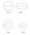
- FIGS. 1 a to 1 dschematically show examples of shapes of a unitary rolling vehicle according to the present invention.
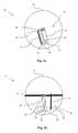
- FIGS. 2 a to 2 cschematically show an embodiment of a unitary rolling vehicle according to the present invention.
- FIG. 3shows a perspective view of an area to be traversed by a unitary rolling vehicle according to the present invention.
- FIG. 4illustrates a specific complicated situation for a unitary rolling vehicle according to the present invention.
- FIG. 5illustrates an implemented PID-controller for controlling the motion of the unitary rolling vehicle according to the invention.
- FIG. 6illustrates a basic configuration of a dynamically controlled unitary rolling vehicle for the unitary controlled rolling vehicle system according to the present invention.
- FIG. 7shows an embodiment of interior electronics of the unitary rolling vehicle according to the present invention.
- FIG. 8illustrates one embodiment of a complete unitary rolling vehicle system according to the present invention.
- the rolling member of the unitary rolling vehiclemay be of any suitable shape that allows a rolling movement.
- FIGS. 1 a - 1 dare showing examples of possible shapes, 1 a is showing a sphere, 1 b a pumpkin-shape, 1 c a wheel-shape and 1 d a torus. Other shapes, for example the shape of barrel, are also possible.
- the rolling memberis formed by a shell. This is for illustrative purposes only, and should not be seen as limiting.
- One example of a unitary rolling vehicle of the unitary rolling vehicle system according to the present inventioncomprises one or more of the following features:
- an external battery charging device of the unitary rolling system according to the present inventionmay comprise one or more of the following features:
- an external navigation and monitoring base station of the unitary rolling vehicle systemmay comprise one or more of the following features:
- FIGS. 2 a and 2 bis shown an example of a unitary rolling vehicle in the form of a ball robot comprising a rolling member of spherical shape and a drive system including two mechanical drive units.
- the drive systemis supported by the rolling member, in this example by a diametric main axis.
- the drive mechanism 30comprises a primary motor 50 driving the drive mechanism 30 for rotation about the diametric main axis 40 .
- the primary motor 50is arranged at the lower portion of a primary pendulum 60 , in the vicinity of the inner surface of the shell 20 in order to lower the CM.
- the primary pendulum 60is rotatably supported by the diametric main axis 20 at the upper end, and the primary motor 50 is arranged to drive the primary pendulum for rotation about the main axis 20 by a primary transmission arrangement 70 .
- the primary motor 50may be an electric motor and the primary transmission arrangement 70 can be any suitable transmission arrangement, such as a belt, a chain, or an axis arrangement and the like. Further, the transmission arrangement 70 can be a hydraulic transmission arrangement or the like.
- the primary motor 50is the main power source for driving the ball robot 10 for rotation in the forward and backwards direction.
- the drive mechanismfurther comprises a secondary pendulum 80 and a secondary motor 90 for driving the secondary pendulum 80 for rotation about a secondary axis 100 transverse to the main axis 40 and attached to the primary pendulum 60 .
- the secondary pendulum 80is mainly utilized as a steering means, as rotation in either direction will make the robot 10 ball turn in that direction as the CM will move in that direction.
- the possibilities for the secondary pendulum 80 to influence the movement of the robot ball 10depends on the weight and the centre of mass for the secondary pendulum 80 , hereafter referred to as torque (where high torque for a pendulum is equal to high weight and low CM at rest).
- the secondary pendulum 80has as high torque as possible, compared to the primary pendulum 60 , whereby optimal controllability is achieved.
- the secondary motor 90is arranged at the lower portion of the secondary pendulum 80 , in the vicinity of the inner surface of the shell 20 .
- the secondary motor 90is arranged to drive the secondary pendulum 80 for rotation about the secondary axis 100 by a secondary transmission arrangement 110 .
- the second transmission arrangement 110can be of any type as described for the primary transmission arrangement.
- the secondary pendulum 80is formed such that it can be rotated 360 degrees around the secondary axis 100 .
- CMcentre of mass
- FIG. 2 cshows a more detailed example of the embodiment of the unitary rolling vehicle according to the present invention as disclosed in FIGS. 2 a and 2 b.
- the control system for controlling the drive systemcomprises a control unit that is arranged in or external to the unitary rolling vehicle.
- the control unit and other partsmay be arranged close to the vicinity of the inner surface of the vehicle, for example at the lower part of one of the pendulums, in order to increase the torque of the pendulum.
- the control unit and other partsmay be located in order to lower the centre of mass to further stabilize the vehicle.
- the control systemfurther comprises dynamic state sensors for detecting the instant dynamic state of the vehicle and the drive system.
- the dynamic state sensorsmay include at least a gyroscope, at least an accelerometer and/or at least a rotational sensor for sensing of rotational speed.
- the sensor(s)are located at appropriate places inside the unitary rolling vehicle, and their respective sensed variables are transmitted to the control unit, either wired or wirelessly. It is also possible to transmit the sensed variables to a remote computer outside the vehicle for further processing.
- the control systemincludes three gyroscopes, three accelerometers and one rotational sensor for each motor.
- the gyroscopesare arranged to detect rotation about different axes of rotation and the accelerometers are arranged to detect acceleration/retardation in three different directions.
- the three gyroscopesare arranged to detect rotation about three orthogonal axes of rotation and the accelerometers are arranged to detect acceleration in three orthogonal directions.
- the control systemis capable of detecting any change in dynamic state, such as a sudden change in direction, speed, altitude etc.
- control systemis arranged to analyse the detected instant dynamic state over time and to control vehicle motion by feedback of the instant dynamic state.
- the analysismay be made in an analyse module in the control unit, or in an analyse module in a control unit at a remote place.
- the vehicleDuring normal motion, the vehicle is controlled to move autonomously from one point to another or under operator control, in both situations the control system receives parameters that specifies the desired path of movement and speed.
- the motion of a unitary vehicleis easily disturbed by the ground conditions and the like, or by other dynamic instable states such as wobbling or the like. Therefore the stabilization system is arranged to detect deviations from the desired path and speed, as well as instability deviations and to compensate for such deviations.
- the stable system of the unitary rolling systemeasily becomes unstable when it is on irregular ground, and the control system has to compensate for theses disturbances in a fast and reliable way.
- the control systemmay compensate for instabilities and return to a desired state.
- the control system of the unitary rolling vehicleis further explained below.
- FIG. 4An example of a special difficult situation for the vehicle is shown in FIG. 4 . If a unitary rolling vehicle is directed to traverse over a dosed curve, it has a tendency to lose altitude. This is a difficult situation to analyse and control for the control system, and requires an overall fast control system.
- control systemcomprises at least one analyse module for analysing of sensed data, wherein the analysis is based on multivariate methods.
- a control systemhas been developed that utilizes multivariate control methods to analyze data in real-time from a plurality of sensors. Based on these data, the drive unit(s) of the drive system is/are controlled in order to obtain desired movement.
- control system of the unitary rolling vehiclecomprises one control module comprising at least one controller. This gives the possibility to control the movement pattern of the unitary controlled vehicle in accordance with a desired state.
- the systemworks at a frequency of approximately 300-5000 Hz, which makes a fast enough feedback possible.
- Additional input variablesare filtered sensor readings from various forms of sensors such as mine sensors, gas sensors, cameras, IR sensors, UV detectors, ultrasound transducers, noise detectors, mass spectrometer etc.
- the unitary rolling vehicleis adapted to independently navigate in an essentially unknown environment, only knowing a starting position and an end position, by continuously sensing the dynamic state of the unitary rolling vehicle and controlling the vehicle motion in dependence on the deviation from a desired route.
- the unitary rolling vehicleis adapted to navigate from positioning data retrieved from images taken by a camera system incorporated in the rolling vehicle system.
- the control systemmay consist of one or several subparts/modules organized in a parallel and/or hierarchical manner.
- the vehiclemay be navigated in a variety of ways. It may be controlled by a joystick controlled by an operator, by reference to an internal map of the environment, by knowing a starting point and an end point etc. It may randomly traverse a certain area.
- the unitary rolling vehiclerequires communication and guidance capabilities. This may be implemented in at least one micro controller (MCU) or central processing unit (CPU) or field programmable gate array (FPGA) or Digital Signal Processor (DSP) and/or other digital logical device together with motor electronics.
- MCUmicro controller
- CPUcentral processing unit
- FPGAfield programmable gate array
- DSPDigital Signal Processor
- the present inventionallow the electronics to be implemented in a distributed system, i.e. over several digital logical devices (distributed intelligence) operated over a distributed bus. However this is not required and the same set of functions and/or sensors can be implemented on a single CPU. In FIG. 7 this is illustrated in a set of units, where the communication unit is responsible for communication with other vehicles and/or RTS and/or satellites.
- the House Keeping Unitcollects data from GPS receiver, Sun Sensors, Accelerometers, Gyroscopes, Rotational Sensors, Inclinometers, Obstacle detectors, Power consumption, Temperatures, and any additional equipment with additional data sensing and/or sensor and/or actuator.
- the House Keeping Unitprocesses these data and feed the Guidance Unit with guidance inputs.
- the house keeping unitalso control and/or monitors the battery recharge procedure or battery status during operation.
- the guidance unitcontrols at least one motor or more according to the guidance data, which can be both autonomously acquired or remotely controlled.
- FIG. 8illustrates one embodiment of a complete unitary rolling vehicle system, with a data/monitoring control station, a recharge station, Robot Transceiver Station, and unitary rolling vehicles (here called robots).
- the transfer of information between the RTS, data/monitoring station, charging stationis made over a secure line using optical transmission, and/or LAN and/or WLAN at available speeds.
- the data/monitoring stationmonitors and controls both the charging station and the RTS. Recharging of the vehicles is made autonomously, where two modes are possible; the vehicle determines autonomously that a threshold limit has been reached and returns to the charging station.
- the second optionis that the data/monitoring station either autonomously or on active command tells any or all of the available vehicles to return to the charging station.
- the data/monitoring stationhave a Graphical User Interface (GUI) for control/monitoring of the complete system.
- GUIGraphical User Interface
- An internet connectioncan be added to the data/monitoring station and in that mode the data/monitoring station can act as a web server for remote service of the unitary rolling vehicle system.
- the data/monitoring stationwill have firewall functions to protect the system from intrusion or un-authorized access. Connecting of the internet to the data/monitoring station allows the internal network to utilize the full set of IP-numbers, (that is with IP version 6, 1021 numbers/m2 of the surface of the Earth).
- RTS and/or charging stationscan be added to the system through the internal LAN/WLAN switch. Additional switches can be added to the internal LAN/WLAN switch to fulfil the connection need of RTS and/or charging stations.
Landscapes
- Engineering & Computer Science (AREA)
- Mechanical Engineering (AREA)
- Power Engineering (AREA)
- Transportation (AREA)
- Robotics (AREA)
- Control Of Position, Course, Altitude, Or Attitude Of Moving Bodies (AREA)
Abstract
Description
- Pendulum type comprising a main axis connected diametrically to a rolling member and supporting a drive mechanism arranged to drive a ballast pendulum for rotation around the main axis.
- Shell drive type with a drive mechanism that is supported by and moveable along the rolling member inner surface.
- an encapsulating shell with a hollow main axis;
- a mechanical driving unit situated inside the shell;
- a battery power supply system inside or outside the shell;
- a wireless communication unit including one or several antennas for transmitting and receiving data to and from one or several base stations.
- a computer processing unit for storing, receiving and transmitting data,
- a house keeping sensor unit for sensing, collecting and transmitting measurable physical quantities/changes inside the shell.
- a sensor system unit for sensing, collecting and transmitting measurable physical quantities/changes on or outside the shell.
- an actuator system unit for controlling the mechanical driving device and other actuators such as loudspeakers, video projectors, and other passive and active sensors (ultrasound, laser, sonar, . . . ).
- a sensor signal processing unit for signal processing of the sensor data delivered by the sensor systems.
- one or several control modules for analyzing collected data and regulate the unitary rolling vehicle based on the analyzed data.
- a wireless communication unit.
- an inductive charging device.
- a docking mechanism.
- a transmission and receiving unit that communicated with the vehicle apparatus platform (its wireless communication unit).
- a display unit that continuously processes and visualizes significant data transmitted from the vehicle apparatus platform.
- a navigation unit comprising a conventional joy stick connected to one of several antennas that communicates with the vehicle apparatus platform and its mechanical control system unit.
- an action unit that allows a manual operator activate the different actuators onboard the unitary rolling vehicle platform.
- one or several analyzing modules for analyzing collected data.
- one or several control modules for control of the unitary rolling vehicle based on the analyzed data.
- 1) Stable realization of robust path following for e.g. surveillance tasks
- 2) Stable and improved recognition performance for objects and humans.
- 3) User-friendly access to obstacle avoidance.
- 4) Robust localization of vehicle based on a combination of GPS sensor readouts and local sensor input features.
- 5) Concrete possibilities to obtain various degrees of autonomous behaviour that will be perceived as intelligent behaviour by a human observer (like in autonomous search and recognition of objects and humans).
Claims (12)
Applications Claiming Priority (4)
| Application Number | Priority Date | Filing Date | Title |
|---|---|---|---|
| SE0801053 | 2008-05-09 | ||
| SE0801053-0 | 2008-05-09 | ||
| SE0801053 | 2008-05-09 | ||
| PCT/SE2009/050497WO2009136857A1 (en) | 2008-05-09 | 2009-05-07 | Unitary rolling vehicle |
Publications (2)
| Publication Number | Publication Date |
|---|---|
| US20110060492A1 US20110060492A1 (en) | 2011-03-10 |
| US8670889B2true US8670889B2 (en) | 2014-03-11 |
Family
ID=41130452
Family Applications (1)
| Application Number | Title | Priority Date | Filing Date |
|---|---|---|---|
| US12/991,735Active2030-07-29US8670889B2 (en) | 2008-05-09 | 2009-05-07 | Unitary rolling vehicle |
Country Status (3)
| Country | Link |
|---|---|
| US (1) | US8670889B2 (en) |
| EP (1) | EP2303519A1 (en) |
| WO (1) | WO2009136857A1 (en) |
Cited By (15)
| Publication number | Priority date | Publication date | Assignee | Title |
|---|---|---|---|---|
| US20120173048A1 (en)* | 2011-01-05 | 2012-07-05 | Bernstein Ian H | Self-propelled device implementing three-dimensional control |
| US9090214B2 (en) | 2011-01-05 | 2015-07-28 | Orbotix, Inc. | Magnetically coupled accessory for a self-propelled device |
| US20150237828A1 (en)* | 2014-02-18 | 2015-08-27 | Rosse Mary Peavey | Fun ball |
| US20150245593A1 (en)* | 2014-03-03 | 2015-09-03 | Jason E. O'mara | Autonomous motion device, system, and method |
| US9218316B2 (en) | 2011-01-05 | 2015-12-22 | Sphero, Inc. | Remotely controlling a self-propelled device in a virtualized environment |
| US9280717B2 (en) | 2012-05-14 | 2016-03-08 | Sphero, Inc. | Operating a computing device by detecting rounded objects in an image |
| US9292758B2 (en) | 2012-05-14 | 2016-03-22 | Sphero, Inc. | Augmentation of elements in data content |
| US9429940B2 (en) | 2011-01-05 | 2016-08-30 | Sphero, Inc. | Self propelled device with magnetic coupling |
| US9545542B2 (en) | 2011-03-25 | 2017-01-17 | May Patents Ltd. | System and method for a motion sensing device which provides a visual or audible indication |
| US9829882B2 (en) | 2013-12-20 | 2017-11-28 | Sphero, Inc. | Self-propelled device with center of mass drive system |
| US9827487B2 (en) | 2012-05-14 | 2017-11-28 | Sphero, Inc. | Interactive augmented reality using a self-propelled device |
| US10056791B2 (en) | 2012-07-13 | 2018-08-21 | Sphero, Inc. | Self-optimizing power transfer |
| US10168701B2 (en) | 2011-01-05 | 2019-01-01 | Sphero, Inc. | Multi-purposed self-propelled device |
| US10308134B2 (en) | 2017-03-02 | 2019-06-04 | The Goodyear Tire & Rubber Company | Spherical wheel/tire assembly |
| US20210205983A1 (en)* | 2020-01-03 | 2021-07-08 | Shenzhen Institute Of Artificial Intelligence And Robotics For Society | Self-reconfigurable robot module and self-reconfigurable robot |
Families Citing this family (10)
| Publication number | Priority date | Publication date | Assignee | Title |
|---|---|---|---|---|
| SE0402672D0 (en)* | 2004-11-02 | 2004-11-02 | Viktor Kaznov | Ball robot |
| US8910734B2 (en) | 2010-09-29 | 2014-12-16 | 7312903 Canada, Inc. | Robotic ball device with improved robustness and a multitude of interactive and sensing capabilities |
| CN102152311B (en)* | 2011-03-14 | 2012-08-01 | 哈尔滨工业大学 | Spherical robot driven by double eccentric mass blocks |
| CN102962842B (en)* | 2012-10-29 | 2014-12-10 | 安凯 | Spherical robot driving system and control method thereof |
| CN104925156A (en)* | 2015-05-20 | 2015-09-23 | 苏州市职业大学 | All-direction spherical robot driving device |
| CN105549592B (en)* | 2015-12-22 | 2018-03-20 | 福州大学 | A kind of intelligent spherical robot and its control method with faults-tolerant control |
| CN108781247A (en)* | 2016-02-22 | 2018-11-09 | 凯特切普恩股份有限公司 | Self-propelling instrument |
| JP6653446B2 (en)* | 2016-05-06 | 2020-02-26 | パナソニックIpマネジメント株式会社 | robot |
| US11156457B2 (en)* | 2017-12-14 | 2021-10-26 | Sphero, Inc. | Systems and methods for device detection of presence and manipulations |
| US12097925B1 (en)* | 2021-04-05 | 2024-09-24 | Guardbot Inc | Pendulum-driven unmanned vehicle |
Citations (9)
| Publication number | Priority date | Publication date | Assignee | Title |
|---|---|---|---|---|
| US5791425A (en) | 1993-02-24 | 1998-08-11 | Deka Products Limited Partnership | Control loop for transportation vehicles |
| US6227933B1 (en)* | 1999-06-15 | 2001-05-08 | Universite De Sherbrooke | Robot ball |
| US6289263B1 (en) | 1997-12-16 | 2001-09-11 | Board Of Trustees Operating Michigan State University | Spherical mobile robot |
| US6302230B1 (en) | 1999-06-04 | 2001-10-16 | Deka Products Limited Partnership | Personal mobility vehicles and methods |
| US6378634B1 (en) | 2000-11-28 | 2002-04-30 | Xerox Corporation | Tracking device |
| US6702050B1 (en) | 2002-09-23 | 2004-03-09 | The United States Of America As Represented By The Secretary Of The Army | Robotic vehicle construction |
| WO2006049559A1 (en) | 2004-11-02 | 2006-05-11 | Viktor Kaznov | Ball robot |
| US20070215394A1 (en) | 2006-03-15 | 2007-09-20 | Sun Hanxu | Spherical walking robot |
| EP1563716B1 (en) | 2002-11-18 | 2008-02-13 | Everteq | Computerized automated dynamic control system for single-track vehicles |
- 2009
- 2009-05-07WOPCT/SE2009/050497patent/WO2009136857A1/enactiveApplication Filing
- 2009-05-07EPEP09742939Apatent/EP2303519A1/ennot_activeWithdrawn
- 2009-05-07USUS12/991,735patent/US8670889B2/enactiveActive
Patent Citations (9)
| Publication number | Priority date | Publication date | Assignee | Title |
|---|---|---|---|---|
| US5791425A (en) | 1993-02-24 | 1998-08-11 | Deka Products Limited Partnership | Control loop for transportation vehicles |
| US6289263B1 (en) | 1997-12-16 | 2001-09-11 | Board Of Trustees Operating Michigan State University | Spherical mobile robot |
| US6302230B1 (en) | 1999-06-04 | 2001-10-16 | Deka Products Limited Partnership | Personal mobility vehicles and methods |
| US6227933B1 (en)* | 1999-06-15 | 2001-05-08 | Universite De Sherbrooke | Robot ball |
| US6378634B1 (en) | 2000-11-28 | 2002-04-30 | Xerox Corporation | Tracking device |
| US6702050B1 (en) | 2002-09-23 | 2004-03-09 | The United States Of America As Represented By The Secretary Of The Army | Robotic vehicle construction |
| EP1563716B1 (en) | 2002-11-18 | 2008-02-13 | Everteq | Computerized automated dynamic control system for single-track vehicles |
| WO2006049559A1 (en) | 2004-11-02 | 2006-05-11 | Viktor Kaznov | Ball robot |
| US20070215394A1 (en) | 2006-03-15 | 2007-09-20 | Sun Hanxu | Spherical walking robot |
Non-Patent Citations (3)
| Title |
|---|
| Aarne Halme et al., "Motion Control of a Spherical Mobile Robot", Advanced Motion Control, Mar. 18, 1996, pp. 259-264, vol. 1. |
| International Search Report, dated Oct. 26, 2009, from corresponding PCT application. |
| J. Alves et al., "Design and control of a spherical mobile robot", Proceedings of the Institution of Mechanical Engineers, Part 1 (Journal of Systems and Control Engineering), 2003, pp. 457-467, vol. 217, No. I6. |
Cited By (77)
| Publication number | Priority date | Publication date | Assignee | Title |
|---|---|---|---|---|
| US9836046B2 (en) | 2011-01-05 | 2017-12-05 | Adam Wilson | System and method for controlling a self-propelled device using a dynamically configurable instruction library |
| US20120168241A1 (en)* | 2011-01-05 | 2012-07-05 | Bernstein Ian H | Self-propelled device for interpreting input from a controller device |
| US9090214B2 (en) | 2011-01-05 | 2015-07-28 | Orbotix, Inc. | Magnetically coupled accessory for a self-propelled device |
| US9114838B2 (en)* | 2011-01-05 | 2015-08-25 | Sphero, Inc. | Self-propelled device for interpreting input from a controller device |
| US12001203B2 (en) | 2011-01-05 | 2024-06-04 | Sphero, Inc. | Self propelled device with magnetic coupling |
| US11630457B2 (en) | 2011-01-05 | 2023-04-18 | Sphero, Inc. | Multi-purposed self-propelled device |
| US9150263B2 (en)* | 2011-01-05 | 2015-10-06 | Sphero, Inc. | Self-propelled device implementing three-dimensional control |
| US9193404B2 (en) | 2011-01-05 | 2015-11-24 | Sphero, Inc. | Self-propelled device with actively engaged drive system |
| US9211920B1 (en) | 2011-01-05 | 2015-12-15 | Sphero, Inc. | Magnetically coupled accessory for a self-propelled device |
| US9218316B2 (en) | 2011-01-05 | 2015-12-22 | Sphero, Inc. | Remotely controlling a self-propelled device in a virtualized environment |
| US11460837B2 (en) | 2011-01-05 | 2022-10-04 | Sphero, Inc. | Self-propelled device with actively engaged drive system |
| US9290220B2 (en) | 2011-01-05 | 2016-03-22 | Sphero, Inc. | Orienting a user interface of a controller for operating a self-propelled device |
| US10678235B2 (en) | 2011-01-05 | 2020-06-09 | Sphero, Inc. | Self-propelled device with actively engaged drive system |
| US9389612B2 (en) | 2011-01-05 | 2016-07-12 | Sphero, Inc. | Self-propelled device implementing three-dimensional control |
| US9394016B2 (en) | 2011-01-05 | 2016-07-19 | Sphero, Inc. | Self-propelled device for interpreting input from a controller device |
| US9395725B2 (en) | 2011-01-05 | 2016-07-19 | Sphero, Inc. | Self-propelled device implementing three-dimensional control |
| US9429940B2 (en) | 2011-01-05 | 2016-08-30 | Sphero, Inc. | Self propelled device with magnetic coupling |
| US9457730B2 (en) | 2011-01-05 | 2016-10-04 | Sphero, Inc. | Self propelled device with magnetic coupling |
| US9481410B2 (en) | 2011-01-05 | 2016-11-01 | Sphero, Inc. | Magnetically coupled accessory for a self-propelled device |
| US10423155B2 (en)* | 2011-01-05 | 2019-09-24 | Sphero, Inc. | Self propelled device with magnetic coupling |
| US20120173048A1 (en)* | 2011-01-05 | 2012-07-05 | Bernstein Ian H | Self-propelled device implementing three-dimensional control |
| US10281915B2 (en) | 2011-01-05 | 2019-05-07 | Sphero, Inc. | Multi-purposed self-propelled device |
| US10248118B2 (en) | 2011-01-05 | 2019-04-02 | Sphero, Inc. | Remotely controlling a self-propelled device in a virtualized environment |
| US10168701B2 (en) | 2011-01-05 | 2019-01-01 | Sphero, Inc. | Multi-purposed self-propelled device |
| US10022643B2 (en) | 2011-01-05 | 2018-07-17 | Sphero, Inc. | Magnetically coupled accessory for a self-propelled device |
| US10012985B2 (en) | 2011-01-05 | 2018-07-03 | Sphero, Inc. | Self-propelled device for interpreting input from a controller device |
| US9766620B2 (en) | 2011-01-05 | 2017-09-19 | Sphero, Inc. | Self-propelled device with actively engaged drive system |
| US9952590B2 (en) | 2011-01-05 | 2018-04-24 | Sphero, Inc. | Self-propelled device implementing three-dimensional control |
| US9886032B2 (en) | 2011-01-05 | 2018-02-06 | Sphero, Inc. | Self propelled device with magnetic coupling |
| US9841758B2 (en) | 2011-01-05 | 2017-12-12 | Sphero, Inc. | Orienting a user interface of a controller for operating a self-propelled device |
| US9545542B2 (en) | 2011-03-25 | 2017-01-17 | May Patents Ltd. | System and method for a motion sensing device which provides a visual or audible indication |
| US11631996B2 (en) | 2011-03-25 | 2023-04-18 | May Patents Ltd. | Device for displaying in response to a sensed motion |
| US12288992B2 (en) | 2011-03-25 | 2025-04-29 | May Patents Ltd. | Device for displaying in response to a sensed motion |
| US9868034B2 (en) | 2011-03-25 | 2018-01-16 | May Patents Ltd. | System and method for a motion sensing device which provides a visual or audible indication |
| US9878214B2 (en) | 2011-03-25 | 2018-01-30 | May Patents Ltd. | System and method for a motion sensing device which provides a visual or audible indication |
| US9878228B2 (en) | 2011-03-25 | 2018-01-30 | May Patents Ltd. | System and method for a motion sensing device which provides a visual or audible indication |
| US9808678B2 (en) | 2011-03-25 | 2017-11-07 | May Patents Ltd. | Device for displaying in respose to a sensed motion |
| US9782637B2 (en) | 2011-03-25 | 2017-10-10 | May Patents Ltd. | Motion sensing device which provides a signal in response to the sensed motion |
| US9764201B2 (en) | 2011-03-25 | 2017-09-19 | May Patents Ltd. | Motion sensing device with an accelerometer and a digital display |
| US9757624B2 (en) | 2011-03-25 | 2017-09-12 | May Patents Ltd. | Motion sensing device which provides a visual indication with a wireless signal |
| US12249841B2 (en) | 2011-03-25 | 2025-03-11 | May Patents Ltd. | Device for displaying in response to a sensed motion |
| US9630062B2 (en) | 2011-03-25 | 2017-04-25 | May Patents Ltd. | System and method for a motion sensing device which provides a visual or audible indication |
| US12249842B2 (en) | 2011-03-25 | 2025-03-11 | May Patents Ltd. | Device for displaying in response to a sensed motion |
| US9592428B2 (en) | 2011-03-25 | 2017-03-14 | May Patents Ltd. | System and method for a motion sensing device which provides a visual or audible indication |
| US9555292B2 (en) | 2011-03-25 | 2017-01-31 | May Patents Ltd. | System and method for a motion sensing device which provides a visual or audible indication |
| US12244153B2 (en) | 2011-03-25 | 2025-03-04 | May Patents Ltd. | Device for displaying in response to a sensed motion |
| US12191675B2 (en) | 2011-03-25 | 2025-01-07 | May Patents Ltd. | Device for displaying in response to a sensed motion |
| US10525312B2 (en) | 2011-03-25 | 2020-01-07 | May Patents Ltd. | Device for displaying in response to a sensed motion |
| US12095277B2 (en) | 2011-03-25 | 2024-09-17 | May Patents Ltd. | Device for displaying in response to a sensed motion |
| US11979029B2 (en) | 2011-03-25 | 2024-05-07 | May Patents Ltd. | Device for displaying in response to a sensed motion |
| US10926140B2 (en) | 2011-03-25 | 2021-02-23 | May Patents Ltd. | Device for displaying in response to a sensed motion |
| US10953290B2 (en) | 2011-03-25 | 2021-03-23 | May Patents Ltd. | Device for displaying in response to a sensed motion |
| US11949241B2 (en) | 2011-03-25 | 2024-04-02 | May Patents Ltd. | Device for displaying in response to a sensed motion |
| US11141629B2 (en) | 2011-03-25 | 2021-10-12 | May Patents Ltd. | Device for displaying in response to a sensed motion |
| US11173353B2 (en) | 2011-03-25 | 2021-11-16 | May Patents Ltd. | Device for displaying in response to a sensed motion |
| US11192002B2 (en) | 2011-03-25 | 2021-12-07 | May Patents Ltd. | Device for displaying in response to a sensed motion |
| US11260273B2 (en) | 2011-03-25 | 2022-03-01 | May Patents Ltd. | Device for displaying in response to a sensed motion |
| US11298593B2 (en) | 2011-03-25 | 2022-04-12 | May Patents Ltd. | Device for displaying in response to a sensed motion |
| US11305160B2 (en) | 2011-03-25 | 2022-04-19 | May Patents Ltd. | Device for displaying in response to a sensed motion |
| US11916401B2 (en) | 2011-03-25 | 2024-02-27 | May Patents Ltd. | Device for displaying in response to a sensed motion |
| US11689055B2 (en) | 2011-03-25 | 2023-06-27 | May Patents Ltd. | System and method for a motion sensing device |
| US11605977B2 (en) | 2011-03-25 | 2023-03-14 | May Patents Ltd. | Device for displaying in response to a sensed motion |
| US11631994B2 (en) | 2011-03-25 | 2023-04-18 | May Patents Ltd. | Device for displaying in response to a sensed motion |
| US9483876B2 (en) | 2012-05-14 | 2016-11-01 | Sphero, Inc. | Augmentation of elements in a data content |
| US9827487B2 (en) | 2012-05-14 | 2017-11-28 | Sphero, Inc. | Interactive augmented reality using a self-propelled device |
| US9280717B2 (en) | 2012-05-14 | 2016-03-08 | Sphero, Inc. | Operating a computing device by detecting rounded objects in an image |
| US10192310B2 (en) | 2012-05-14 | 2019-01-29 | Sphero, Inc. | Operating a computing device by detecting rounded objects in an image |
| US9292758B2 (en) | 2012-05-14 | 2016-03-22 | Sphero, Inc. | Augmentation of elements in data content |
| US10056791B2 (en) | 2012-07-13 | 2018-08-21 | Sphero, Inc. | Self-optimizing power transfer |
| US11454963B2 (en) | 2013-12-20 | 2022-09-27 | Sphero, Inc. | Self-propelled device with center of mass drive system |
| US10620622B2 (en) | 2013-12-20 | 2020-04-14 | Sphero, Inc. | Self-propelled device with center of mass drive system |
| US9829882B2 (en) | 2013-12-20 | 2017-11-28 | Sphero, Inc. | Self-propelled device with center of mass drive system |
| US20150237828A1 (en)* | 2014-02-18 | 2015-08-27 | Rosse Mary Peavey | Fun ball |
| US20150245593A1 (en)* | 2014-03-03 | 2015-09-03 | Jason E. O'mara | Autonomous motion device, system, and method |
| US10308134B2 (en) | 2017-03-02 | 2019-06-04 | The Goodyear Tire & Rubber Company | Spherical wheel/tire assembly |
| US12023809B2 (en)* | 2020-01-03 | 2024-07-02 | Shenzhen Institute Of Artificial Intelligence And Robotics For Society | Self-reconfigurable robot module and self-reconfigurable robot |
| US20210205983A1 (en)* | 2020-01-03 | 2021-07-08 | Shenzhen Institute Of Artificial Intelligence And Robotics For Society | Self-reconfigurable robot module and self-reconfigurable robot |
Also Published As
| Publication number | Publication date |
|---|---|
| EP2303519A1 (en) | 2011-04-06 |
| WO2009136857A1 (en) | 2009-11-12 |
| US20110060492A1 (en) | 2011-03-10 |
Similar Documents
| Publication | Publication Date | Title |
|---|---|---|
| US8670889B2 (en) | Unitary rolling vehicle | |
| US8099189B2 (en) | Ball robot | |
| US11216006B2 (en) | Robot and method for localizing a robot | |
| US8326469B2 (en) | Autonomous behaviors for a remote vehicle | |
| US8108092B2 (en) | Autonomous behaviors for a remote vehicle | |
| US8843244B2 (en) | Autonomous behaviors for a remove vehicle | |
| US7843431B2 (en) | Control system for a remote vehicle | |
| WO2008060689A2 (en) | Autonomous behaviors for a remote vehicle | |
| Gadekar et al. | Rakshak: A modular unmanned ground vehicle for surveillance and logistics operations. | |
| Kang et al. | ROBHAZ-rescue: rough-terrain negotiable teleoperated mobile robot for rescue mission | |
| Najafi et al. | RoboCup rescue 2016 team description paper MRL | |
| WO2009136856A1 (en) | Image generation system | |
| Yoshida et al. | Field experiment on multiple mobile robots conducted in an underground mall | |
| Gadekar et al. | Recent developments in the applications of two-wheeled robots: a review | |
| Chothani et al. | Prototype Design of A UGV for Military Purpose | |
| Sahin et al. | System of autonomous rovers and their applications | |
| Mohapatra | Surveillance with Smart Spherical Robot | |
| Chen et al. | Control and Collaboration of Self-Balancing Spherical Robots | |
| Mukherjee et al. | R2D2: Rotating-turret 2D-scanning and dead-reckoning for remotely operated rovers over resource constrained network systems | |
| Xiao | Design, development and evaluation of an experimental platform for network robotics application |
Legal Events
| Date | Code | Title | Description |
|---|---|---|---|
| AS | Assignment | Owner name:ROTUNDUS AB, SWEDEN Free format text:ASSIGNMENT OF ASSIGNORS INTEREST;ASSIGNOR:KAZNOV, VIKTOR;REEL/FRAME:026048/0336 Effective date:20110110 | |
| FEPP | Fee payment procedure | Free format text:PAYOR NUMBER ASSIGNED (ORIGINAL EVENT CODE: ASPN); ENTITY STATUS OF PATENT OWNER: SMALL ENTITY | |
| STCF | Information on status: patent grant | Free format text:PATENTED CASE | |
| CC | Certificate of correction | ||
| MAFP | Maintenance fee payment | Free format text:PAYMENT OF MAINTENANCE FEE, 4TH YR, SMALL ENTITY (ORIGINAL EVENT CODE: M2551) Year of fee payment:4 | |
| AS | Assignment | Owner name:LUOTENG TECHNOLOGY (HANGZHOU) CO. LTD., CHINA Free format text:ASSIGNMENT OF ASSIGNORS INTEREST;ASSIGNOR:ROTUNDUS AB;REEL/FRAME:045133/0305 Effective date:20180208 | |
| AS | Assignment | Owner name:LUOTENG TECHNOLOGY (HANGZHOU) CO. LTD., CHINA Free format text:ASSIGNMENT OF ASSIGNORS INTEREST;ASSIGNOR:ROTUNDUS AB;REEL/FRAME:045175/0087 Effective date:20180208 | |
| MAFP | Maintenance fee payment | Free format text:PAYMENT OF MAINTENANCE FEE, 8TH YR, SMALL ENTITY (ORIGINAL EVENT CODE: M2552); ENTITY STATUS OF PATENT OWNER: SMALL ENTITY Year of fee payment:8 | |
| MAFP | Maintenance fee payment | Free format text:PAYMENT OF MAINTENANCE FEE, 12TH YR, SMALL ENTITY (ORIGINAL EVENT CODE: M2553); ENTITY STATUS OF PATENT OWNER: SMALL ENTITY Year of fee payment:12 |