US8668735B2 - Corneal implant storage and delivery devices - Google Patents
Corneal implant storage and delivery devicesDownload PDFInfo
- Publication number
- US8668735B2 US8668735B2US13/657,650US201213657650AUS8668735B2US 8668735 B2US8668735 B2US 8668735B2US 201213657650 AUS201213657650 AUS 201213657650AUS 8668735 B2US8668735 B2US 8668735B2
- Authority
- US
- United States
- Prior art keywords
- implant
- corneal
- applicator
- support
- corneal implant
- Prior art date
- Legal status (The legal status is an assumption and is not a legal conclusion. Google has not performed a legal analysis and makes no representation as to the accuracy of the status listed.)
- Expired - Fee Related
Links
- 239000007943implantSubstances0.000titleclaimsabstractdescription277
- 238000003860storageMethods0.000titledescription18
- 238000000034methodMethods0.000claimsabstractdescription25
- 238000000151depositionMethods0.000claimsabstractdescription12
- 239000012530fluidSubstances0.000claimsdescription29
- 238000004806packaging method and processMethods0.000abstractdescription7
- 230000001070adhesive effectEffects0.000description19
- 239000000853adhesiveSubstances0.000description18
- 239000007788liquidSubstances0.000description17
- 239000000463materialSubstances0.000description16
- XLYOFNOQVPJJNP-UHFFFAOYSA-NwaterSubstancesOXLYOFNOQVPJJNP-UHFFFAOYSA-N0.000description8
- 229910001220stainless steelInorganic materials0.000description7
- 239000010935stainless steelSubstances0.000description7
- 210000004087corneaAnatomy0.000description6
- -1polypropylenePolymers0.000description6
- 229920000642polymerPolymers0.000description5
- 239000000017hydrogelSubstances0.000description4
- 230000000670limiting effectEffects0.000description4
- 210000001747pupilAnatomy0.000description4
- 239000004743PolypropyleneSubstances0.000description3
- RTAQQCXQSZGOHL-UHFFFAOYSA-NTitaniumChemical compound[Ti]RTAQQCXQSZGOHL-UHFFFAOYSA-N0.000description3
- 238000004519manufacturing processMethods0.000description3
- 229910052751metalInorganic materials0.000description3
- 239000002184metalSubstances0.000description3
- 239000004033plasticSubstances0.000description3
- 229920001155polypropylenePolymers0.000description3
- 229920001343polytetrafluoroethylenePolymers0.000description3
- 239000004810polytetrafluoroethyleneSubstances0.000description3
- 239000010936titaniumSubstances0.000description3
- 229910052719titaniumInorganic materials0.000description3
- 0C*N*CCCCC=*Chemical compoundC*N*CCCCC=*0.000description2
- 239000004809TeflonSubstances0.000description2
- 229920006362Teflon®Polymers0.000description2
- 230000002745absorbentEffects0.000description2
- 239000002250absorbentSubstances0.000description2
- 230000006978adaptationEffects0.000description2
- 239000011324beadSubstances0.000description2
- 238000003486chemical etchingMethods0.000description2
- 230000008021depositionEffects0.000description2
- 238000009760electrical discharge machiningMethods0.000description2
- 230000036961partial effectEffects0.000description2
- 230000000717retained effectEffects0.000description2
- 238000000926separation methodMethods0.000description2
- BFKJFAAPBSQJPD-UHFFFAOYSA-NtetrafluoroetheneChemical compoundFC(F)=C(F)FBFKJFAAPBSQJPD-UHFFFAOYSA-N0.000description2
- 238000003466weldingMethods0.000description2
- QRMPKOFEUHIBNM-UHFFFAOYSA-NCC1CCC(C)CC1Chemical compoundCC1CCC(C)CC1QRMPKOFEUHIBNM-UHFFFAOYSA-N0.000description1
- 229920000742CottonPolymers0.000description1
- 241000238631HexapodaSpecies0.000description1
- FAPWRFPIFSIZLT-UHFFFAOYSA-MSodium chlorideChemical compound[Na+].[Cl-]FAPWRFPIFSIZLT-UHFFFAOYSA-M0.000description1
- 238000013459approachMethods0.000description1
- 230000000295complement effectEffects0.000description1
- 230000006835compressionEffects0.000description1
- 238000007906compressionMethods0.000description1
- 238000005520cutting processMethods0.000description1
- 210000000887faceAnatomy0.000description1
- 238000010348incorporationMethods0.000description1
- 238000003698laser cuttingMethods0.000description1
- 239000012528membraneSubstances0.000description1
- 230000005499meniscusEffects0.000description1
- 238000000465mouldingMethods0.000description1
- 230000003287optical effectEffects0.000description1
- 229920002492poly(sulfone)Polymers0.000description1
- 239000002861polymer materialSubstances0.000description1
- 238000012545processingMethods0.000description1
- 230000002829reductive effectEffects0.000description1
- 230000000284resting effectEffects0.000description1
- 239000011780sodium chlorideSubstances0.000description1
- 239000007787solidSubstances0.000description1
- 238000012800visualizationMethods0.000description1
Images


Classifications
- A—HUMAN NECESSITIES
- A61—MEDICAL OR VETERINARY SCIENCE; HYGIENE
- A61F—FILTERS IMPLANTABLE INTO BLOOD VESSELS; PROSTHESES; DEVICES PROVIDING PATENCY TO, OR PREVENTING COLLAPSING OF, TUBULAR STRUCTURES OF THE BODY, e.g. STENTS; ORTHOPAEDIC, NURSING OR CONTRACEPTIVE DEVICES; FOMENTATION; TREATMENT OR PROTECTION OF EYES OR EARS; BANDAGES, DRESSINGS OR ABSORBENT PADS; FIRST-AID KITS
- A61F2/00—Filters implantable into blood vessels; Prostheses, i.e. artificial substitutes or replacements for parts of the body; Appliances for connecting them with the body; Devices providing patency to, or preventing collapsing of, tubular structures of the body, e.g. stents
- A61F2/02—Prostheses implantable into the body
- A61F2/14—Eye parts, e.g. lenses or corneal implants; Artificial eyes
- A61F2/148—Implantation instruments specially adapted therefor
- A—HUMAN NECESSITIES
- A61—MEDICAL OR VETERINARY SCIENCE; HYGIENE
- A61B—DIAGNOSIS; SURGERY; IDENTIFICATION
- A61B50/00—Containers, covers, furniture or holders specially adapted for surgical or diagnostic appliances or instruments, e.g. sterile covers
- A61B50/30—Containers specially adapted for packaging, protecting, dispensing, collecting or disposing of surgical or diagnostic appliances or instruments
- A—HUMAN NECESSITIES
- A61—MEDICAL OR VETERINARY SCIENCE; HYGIENE
- A61F—FILTERS IMPLANTABLE INTO BLOOD VESSELS; PROSTHESES; DEVICES PROVIDING PATENCY TO, OR PREVENTING COLLAPSING OF, TUBULAR STRUCTURES OF THE BODY, e.g. STENTS; ORTHOPAEDIC, NURSING OR CONTRACEPTIVE DEVICES; FOMENTATION; TREATMENT OR PROTECTION OF EYES OR EARS; BANDAGES, DRESSINGS OR ABSORBENT PADS; FIRST-AID KITS
- A61F2/00—Filters implantable into blood vessels; Prostheses, i.e. artificial substitutes or replacements for parts of the body; Appliances for connecting them with the body; Devices providing patency to, or preventing collapsing of, tubular structures of the body, e.g. stents
- A61F2/02—Prostheses implantable into the body
- A61F2/14—Eye parts, e.g. lenses or corneal implants; Artificial eyes
- A61F2/142—Cornea, e.g. artificial corneae, keratoprostheses or corneal implants for repair of defective corneal tissue
- A—HUMAN NECESSITIES
- A61—MEDICAL OR VETERINARY SCIENCE; HYGIENE
- A61F—FILTERS IMPLANTABLE INTO BLOOD VESSELS; PROSTHESES; DEVICES PROVIDING PATENCY TO, OR PREVENTING COLLAPSING OF, TUBULAR STRUCTURES OF THE BODY, e.g. STENTS; ORTHOPAEDIC, NURSING OR CONTRACEPTIVE DEVICES; FOMENTATION; TREATMENT OR PROTECTION OF EYES OR EARS; BANDAGES, DRESSINGS OR ABSORBENT PADS; FIRST-AID KITS
- A61F2/00—Filters implantable into blood vessels; Prostheses, i.e. artificial substitutes or replacements for parts of the body; Appliances for connecting them with the body; Devices providing patency to, or preventing collapsing of, tubular structures of the body, e.g. stents
- A61F2/02—Prostheses implantable into the body
- A61F2/14—Eye parts, e.g. lenses or corneal implants; Artificial eyes
- A61F2/145—Corneal inlays, onlays, or lenses for refractive correction
- A61F2/1451—Inlays or onlays
Definitions
- Corneal implantssuch as corneal onlays and corneal inlays, can be small, delicate medical devices, the storage and/or handling of which should be carefully performed to prevent damage to the implants. Additionally, corneal implants can also be transparent, which, in addition to their small size, can make them difficult to see with the unaided eye.
- Devices and methodsare needed that allow for easy handling and positioning of small, delicate corneal implants without damaging the implant.
- a corneal implant applicator apparatuscomprising a corneal applicator member comprising an applicator; a corneal implant support disposed relative to the applicator to form an implant chamber; and wherein the applicator and the corneal implant support are adapted such that a corneal implant has a greater preference for adhering to the applicator than to the corneal implant support.
- the applicatoris adapted such that the corneal implant has a greater preference for adhering to corneal tissue than to the applicator.
- the applicatorcan have a radius of curvature that is greater than a radius of curvature of an anterior surface of the corneal implant.
- the applicatorhas at least one opening therethrough.
- the corneal implant supportcan also have at least one opening therethrough.
- the corneal implant supporthas a surface with a contour different than a contour of a surface of the applicator, and wherein the different contours provide the corneal implant with the greater preference for adhering to the applicator than to the corneal implant support.
- the applicator surfacecan be smoother than the surface of the corneal implant support.
- the corneal implant supportis adapted to be moved relative to the applicator to provide access to the corneal implant and allow the corneal implant to preferentially adhere to the applicator.
- the corneal implant supportcan be detachably secured to the applicator.
- the apparatuscan further comprise at least one clip adapted to detachably secure the corneal implant support to the applicator.
- the apparatusfurther comprises a fluid disposed within the implant chamber.
- the corneal implantis made from a hydrophilic, such as a hydrogel, material.
- the applicator and corneal implant supportare adapted such that the net adhesive forces between the applicator and the corneal implant are greater than the net adhesive forces between the implant support and the corneal implant, whereby the corneal implant will preferentially adhere to the applicator when the applicator and corneal implant support are moved relative to one another.
- One aspect of the disclosureis a method of depositing a corneal implant onto corneal tissue, comprising providing a corneal implant applicator apparatus, the apparatus comprising a corneal implant applicator, an implant support disposed relative to the corneal implant applicator to form an implant chamber, and a corneal implant disposed in the implant chamber, moving the implant support relative to the corneal implant applicator to provide access to the corneal implant and to allow the corneal implant to preferentially adhere to the corneal implant applicator rather than the implant support, positioning the corneal implant applicator such that the corneal implant engages corneal tissue, and moving the corneal implant applicator from the corneal tissue to allow the corneal implant to preferentially adhere to the corneal tissue rather than the applicator, thereby depositing the corneal implant on the corneal tissue.
- moving the implant support relative to the corneal implant applicatorcomprises removing a securing element that detachably secures the implant support to the corneal implant applicator.
- the methodfurther comprises wicking away fluid from within the implant chamber, wherein the wicking step occurs prior to moving the implant support relative to the corneal implant applicator.
- the methodfurther comprises, prior to the depositing step, creating a corneal flap and lifting the corneal flap to expose the corneal tissue.
- FIGS. 1 a - 3 cillustrate an exemplary corneal implant applicator apparatus.
- FIG. 4illustrates exemplary cohesive forces
- FIG. 5illustrates exemplary adhesive forces
- FIG. 6illustrates a liquid suspended within a loop
- FIGS. 7-13illustrate an exemplary corneal implant applicator apparatus.
- FIGS. 14A-19illustrate exemplary moderate and minimal bodies.
- FIGS. 19-22illustrate an exemplary corneal implant applicator apparatus.
- FIGS. 23A-35Billustrate components of an exemplary corneal implant applicator apparatus.
- the disclosurerelates to devices for one or more of packaging, storing, positioning, and delivering corneal implants such as corneal inlays.
- the devices hereincan be used in the movement and positioning of, for example without limitation, corneal onlays, corneal inlays, corneal replacements, and contact lenses.
- FIGS. 1A-3Cillustrate an exemplary embodiment of an implant packaging and handling system 48 adapted to apply a corneal implant to a corneal surface.
- system 48includes implant carrier member 80 having a handle 50 extending from implant applicator 58 .
- Implant carrier member 80is adapted to detachably couple to implant support member 78 .
- implant support member 78has a handle 52 extending from implant support 56 .
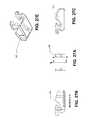
- FIG. 1Billustrates detail “A” shown in FIG. 1A .
- fastening carrier member 80 and support member 78together operably aligns implant applicator 58 and implant support 56 .
- the handle portions 50 and 52are positioned adjacent to one another so as to form a support handle 54 (see FIG. 1A ).
- Concave surface 70 of applicator 58is aligned with convex implant support surface 76 of implant support 56 .
- Surface 70 and surface 76form chamber 88 therebetween, which provides a storage space to retain a corneal implant therein.
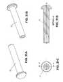
- FIGS. 2A-2Cillustrate views of carrier member 80 (support member 78 not shown for clarity).
- FIG. 2Aillustrates a top view of a portion of carrier member 80 , showing handle 50 and implant applicator 58 .
- FIG. 2Cshows detail “B” from FIG. 2A .
- applicator 58includes a domed portion with upper surface 86 and lower surface 70 .
- Lower surface 70is contoured with a radius of curvature that is greater than the radius of curvature of an anterior surface of the implant that is being packaged (not shown for clarity). The difference in the radii of curvature is advantageous in assisting with the release of the corneal implant from applicator surface 70 .
- a corneal implantgenerally includes a posterior surface that is adapted to make contact with corneal bed tissue, and an anterior surface that faces in the anterior direction and is disposed under overlying corneal tissue (whether the implant is inserted under a flap or into a pocket).
- applicator surface 70(on which an implant is retained) is first positioned immediately over the corneal bed surface such that the implant engages the corneal bed tissue. Applicator 58 (and therefore surface 70 ) is then lifted away from the corneal bed surface. The anterior surface of the implant releases from applicator surface 70 and the posterior surface of the implant remains adhered to the corneal bed surface.
- applicator surface 70has a radius of curvature that is greater than the radius of curvature of the anterior surface of the implant. Due to the difference in radii of curvature, the anterior surface of the implant and applicator surface 70 are not complementary, and thus, are more easily separated. In this manner the corneal implant preferentially adheres to the cornea over applicator surface 70 .
- applicator surface 70has an indented ring or recessed applicator surface (as is shown in FIG. 12 and indicated by numeral 29 in U.S. Pat. No. 6,581,993, incorporated by reference herein).
- the recessed surfacecan be circular, thereby allowing a substantially circular implant to be centrally positioned on applicator surface 70 .
- a plurality of openings 64are provided through applicator surface 70 through which a volume of fluid can be passed to help remove the implant.
- fluidcan be withdrawn through the opening 64 from the implant that is disposed on applicator surface 70 .
- the openings 64provide a fluid passage for drawing fluid away from the implant using a cotton swab, or other absorbent material, that would be positioned against upper surface 86 of applicator 58 .
- optional central opening 66is provided in applicator 58 to assist with the proper alignment of the implant and the deposition of the implant onto the cornea surface.
- a cannula or like instrumentcan be inserted through central opening 66 to depress and assist the release of the implant from applicator surface 70 .
- the diameter of central opening 66is greater than the diameter of openings 64 . In this way, the user is provided with a central point of reference, which enables the user to align applicator surface 70 with the optical axis of the eye, and, thus, properly position the implant.
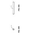
- FIGS. 3A-3Cillustrate different views of support member 78 (carrier member not shown for clarity).
- FIG. 3Cillustrates detail “A” from FIG. 3B .
- Support member 78has handle 52 extending from implant support 56 .
- Implant support 56comprises platform 82 disposed about an upper support surface 76 and an opposing lower surface 90 .
- Lower surface 90is recessed relative to the lower surface of the platform portion 82 .
- Upper surface 76 and lower surface 90have a plurality of openings therethrough to facilitate the passage of liquid to and away from the implant.
- support 56is shown at an angle of 30° relative to handle 52 . It can be advantageous for support 56 to be at an angle relative to handle 52 between about 30° and about 60°. Similarly, the angle between applicator 58 and handle 50 is generally between about 30° and about 60°. In FIG. 2B the angle is 30°. In some embodiments the angle between handle portions 50 and 52 and platform portions 84 and 82 , respectively, is about 45°. It is to be understood that a range of angles can be used without deviating from the scope of the present disclosure.
- FIGS. 1B , 2 A, and 3 Aillustrate an exemplary embodiment in which support member 78 is detachably connected to carrier member 80 .
- the carrier member 80is provided with a pair of notches or grooves, 68 a and 68 b .
- Notches or grooves 68 a and 68 bare located on opposite sides of applicator 58 .
- support member 78is provided with a pair of notches or grooves, 68 c and 68 d , located on opposite sides of implant support 56 .
- Carrier member 80can be securely coupled to support member 78 by aligning notch 68 a with 68 c , and notch 68 b with 68 d , and then positioning a fastening element about the two members and securely within the aligned notches.
- FIG. 1Bshows elastic band 69 , which is placed about members 78 and 80 , secured within each of the respective notches ( 68 a - d ) to secure members 78 and 80 together in a detachable manner.
- metal or plastic clipsare used to fasten together members 78 and 80 . It should be understood, however, that various ways can be utilized to fasten the two members together in a detachable manner without deviating from the scope of the disclosure.
- FIGS. 2B and 3Aillustrate an additional optional way to secure members 78 and 80 together and such that they can be easily separated to prepare the implant for use.
- Handle 52includes slot 74 adapted to receive and interlock with tab 72 of carrier member 80 .
- Tab 72extends from the lower surface of handle 50 of carrier member 80 .
- carrier member 80is positioned in overlapping relation to support member 78 such that tab 72 is inserted into slot 74 .
- tab 72holds carrier member 80 together with support member 78 .
- band 69is then placed about implant applicator 58 and implant support 56 , as is described in more detail above. In use, the user initially removes band 69 or other attachment element from the fastened members 78 and 80 .
- handle 50Once removed, the user simply slides handle 50 in the direction indicated by arrow 98 shown in FIG. 2A , which is generally a proximal direction. In this way, tab 72 slidably disengages from slot 74 and members 78 and 80 are separated. Once separated, carrier member 80 can then be used to deposit the implant onto the cornea surface as set forth above.
- the proximal portion of handle 50is also adapted to be secured to a surgical-style handle or other handle device to more easily deposit the implant onto the corneal bed surface.
- Support surface 76 of implant support 56is adapted such that the implant will preferably remain adhered to applicator surface 70 upon separation of members 78 and 80 .
- support surface 76has a more uneven or rough contour than adjacent applicator surface 70 .
- Applicator surface 70is provided as a smooth or polished surface. In this embodiment, it is not critical that surface 70 be microscopically smooth, though it may be. In this embodiment, however, it is important that surface 70 be smoother than support surface 76 . In this manner, applicator surface 70 has a smoother surface area for directly contacting and adhering to the lens implant.
- Support surface 76is fabricated so as to have a contour characterized by minute bumps or rounded portions along surface 76 .
- this contoured surfacecan be fabricated by manufacturing support surface 76 from polypropylene comprising polytetrafluoroethylene beads embedded in the polypropylene surface. Polytetrafluoroethylene is sold under the trade name TEFLON.
- the beadsmaintain their general conformation when embedded, which results in surface 76 having raised bumps, rounded portions, or the like.
- support surface 76can be roughened, etched, notched, scored or made to be imperfect using any one of molding, stamping or other known mechanical techniques. Surface 76 is less able to adhere to the surface of the implant than is smoother applicator surface 70 , and the implant will preferentially remain adhered to applicator surface 70 upon separation of the members 78 and 80 .
- the implantcan be further directed to remain adhered on applicator surface 70 .
- system 48can be removed from a storage container in which system is disposed (not shown). System 48 is turned such that carrier member 80 is facing downwards and support member 78 is on top. Next, the user simply places an absorbent material against the top surface 60 of applicator portion 58 so as to draw fluid from within chamber 88 through openings 64 . As the fluid is drawn away from chamber 88 the implant is lowered to a resting position against the applicator surface 70 .
- system 48 componentscan be made from a polymer or plastic material.
- system 48 componentscould be made from one or a combination of the following polymers: Polytetrafluoroethylene (sold under the trade name TEFLON), Polypropylene, or Polysulfone (sold under the trade name UDEL).
- portions of each component membercould be made from a polymer or plastic together with a portion comprising stainless steel or other metal or semi-metal.
- handle 50 of carrier member 80can be manufactured from stainless steel, and applicator portion 58 can be manufactured from a polymer material. The handle and applicators could then be welded or interlocked together using various known fabrication techniques. It should also be understood that various other polymers or polymer combinations can be utilized without deviating from the scope of the present invention.
- System 48is adapted to maintain the corneal implant in a hydrated condition during storage and shipping.
- System 48can be positioned within a storage device such as a vial as is described in U.S. Pat. No. 6,543,610, incorporated by reference herein.
- a storage devicesuch as a vial as is described in U.S. Pat. No. 6,543,610, incorporated by reference herein.
- the corneal implantis in contact with a volume of storage fluid.
- the implantis contained within the chamber 88 and maintained in a hydrated condition by the passage of fluid through the respective openings 62 , 64 , and 66 .
- the corneal implantis packaged within chamber 88 defined by applicator surface 70 and carrier support surface 76 .
- the height of this spaceis designed to be sufficiently narrow that the implant remains properly oriented within chamber 88 during storage and handling conditions. In this way, the user simply detaches carrier member 80 from support member 78 and deposits the implant to the corneal surface by placing the applicator surface 70 , on which the implant is adhered, directly to the corneal surface.
- the disclosure belowdescribes devices and methods of use that rely at least partially on surface tension of liquids to control the positioning and/or movement of a corneal implant.
- the devicescan be used in the storage, packaging, movement, or delivering of the corneal implants.
- These approachescan be used when the corneal implant is made at least partially of hydrophilic material, such as a hydrogel.
- Adhesive forcesare those seen between unlike molecules. For some material combinations, these forces can be greater than the cohesive forces of a liquid's molecules. These strong adhesive forces are the cause of an upward ‘bowing,’ called the meniscus (as shown in FIG. 5 ), in a liquid's surface where the liquid around the edge of a container is pulled higher than the rest of the surface by the adhesive forces between the liquid and the container. The adhesive forces pull up on the surface of the water and are in equilibrium with the gravitational forces pulling down on the body of liquid.
- the adhesive and cohesive forcesact in a similar fashion. Many factors, including the type of material, the type of fluid, and the surface geometry will affect the strength of the adhesive and cohesive forces.
- Exemplary corneal implantsthat can be stored and used in the following embodiments are corneal inlays described in U.S. Pub. No. US 2007/0203577, filed Oct. 30, 2006, U.S. Pub. No. US 2008/0262610, filed Apr. 20, 2007, and U.S. Pub. No. 2011/0218623, filed Sep. 8, 2010, the disclosures of which are incorporated herein by reference.
- a “small diameter”i.e., between about 1 mm and about 3 mm
- corneal inlayis made from a hydrogel, that may be primarily fluid. This, as well as the inlay's small size, causes it to behave in somewhat the same way as a fluid.
- corneal implantmakes use of these characteristics of the corneal implant and the adhesion forces between a fluid and various surface geometries. While the disclosure herein focuses on corneal inlays, any corneal implant that exhibits similar properties can be used as described herein. For example, corneal onlays, at least a portion of which have hydrophilic properties, can be used as described herein.
- a body's “affinity” for a fluid or an object with fluid-like propertiese.g., a hydrophilic corneal implant.
- a body's “affinity” for the fluid or fluid-like objectis influenced by the difference between the strength of the net adhesive forces between the body and the fluid or fluid-like object and the strength of the net cohesive forces within the fluid or fluid-like object.
- the relative affinities of two bodies for the fluid or fluid-like objectis at least partially determined by the relative strengths of the net adhesive forces between the bodies and the fluid or fluid-like object.
- a first bodycan have a greater affinity for the implant than a second body when the net adhesive forces between the first body and the implant are greater than the net adhesive forces between the second body and the implant.
- the corneal implantwill remain adhered to the body with the highest net force (the sum of the adhesive and cohesive forces).
- a first bodyreferred to herein as a “moderate body” has a greater affinity for the fluid or fluid-like object than a second body, referred to herein as a “minimal body.”
- bodymay be used interchangeably with device, component, structure, or other similar term to indicate anything with structure.
- the eyehowever, has a greater affinity for the fluid or fluid-like object than the moderate body.
- the different relative affinitiescan be used to handle the inlay and control the movement of the inlay as it is moved from one surface to another without a user needing to touch it with a hand or other tool. Factors that influence the relative affinities include one or more of: the type of material, the type of fluid, and the surface geometry including surface area.
- a corneal inlaye.g., the fluid-like object
- the eyecan be described as having a greater affinity for the inlay than both the moderate body and the minimal body.
- the moderate bodycan be described as having a greater affinity for the inlay than the minimal body. That is, the affinity between two bodies can be described relative to either body. That is, for example, the moderate body has a greater affinity for the inlay than does the minimal body, and thus the inlay will preferentially adhere to the moderate body over the minimal body.
- the storage fluidis water or saline, for example.
- Water moleculesare highly polarized, which provides for attractive forces with other materials.
- a relative comparison of the affinity between each body and the inlaycan be represented by: corneal tissue >moderate body >minimal body.
- the moderate and minimal bodiesmay take on many forms, including, without limitation, meshes, membranes, and/or material with different surface finishes or contours.
- the inlaypreferentially remains adhered to the moderate body. It continues to adhere to the moderate body until exposed to a stronger adhesive force.
- the minimal and moderate bodiescan therefore be any suitable material as long as the adhesive forces between the moderate body and the inlay are greater than the adhesive forces between the minimal body and the inlay.
- the moderate bodyhas a greater affinity for the inlay than does the minimal body, and the adhesive properties of the materials is a factor influencing those affinities.
- FIGS. 7-14Dillustrate an exemplary embodiment of an apparatus that comprises a moderate body and a minimal body, wherein the apparatus also includes an actuation mechanism that is used to separate the minimal body from the corneal implant and the moderate body.
- the apparatuscan be used to store the corneal implant, prepare the corneal implant for delivery, and/or deliver the corneal implant onto or into the eye.
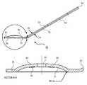
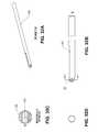
- FIGS. 7 and 8(side view and sectional side view, respectively) illustrate device 100 including handle 112 secured to distal portion 114 .
- Actuator 116is disposed in both handle 112 and distal portion 114 , both of which are adapted to allow actuator 116 to pass therethrough.
- Spring 126maintains actuator 116 in the at-rest, or non-actuated, configuration shown in FIGS. 7 and 8 .
- Actuator 116has a distal section 128 with a reduced size that is disposed in a smaller sized distal channel in distal portion 114 .
- the distal end of apparatus 100includes first portion 118 secured to moderate body 122 .
- a second portion 120is secured to minimal body 124 and is also detachably secured to first portion 118 around pin 134 .
- the corneal implant(not shown in FIGS. 7 and 8 for clarity) is disposed between the moderate body and the minimal body in a nest formed by the moderate and minimal bodies.
- Second portion 120is adapted to rotate with respect to first portion 118 around pin 134 .
- FIG. 9(sectional side view) illustrates the device after actuator 116 has been pressed down. When actuator 116 is pressed, spring 126 is compressed, and distal section 128 moves forward, or distally, through the channel in distal portion 114 .
- distal section 128makes contact with second portion 120 , forcing it downward as it rotates around pin 134 . Because the corneal implant has a higher affinity for moderate body 122 than minimal body 124 , the corneal implant will remain adhered to moderate body 122 as second portion 120 and minimal body 124 are rotated away from first portion 118 and moderate body 122 . Once the curved portion of second portion 120 clears pin 134 , second portion 120 is detached from first portion 118 and therefore from device 100 , preparing the corneal implant for delivery (or, in some embodiments the corneal implant is delivered using a separate delivery device).
- FIG. 10illustrates a perspective view of the distal region of device 100 .
- First portion 118is secured to second portion 120 with clip 132 , which is biased to the closed configuration shown in FIG. 10 .
- clip 132is forced into an open configuration, allowing second portion 120 and minimal body 124 to be rotated away from first portion 118 .
- FIG. 11illustrates a sectional side view of the distal portion of the device.
- FIG. 12shows the sectional side view from FIG. 11 after actuator 116 has been actuated and second portion 120 is rotating away from first portion 118 .
- Corneal implant 140remains adhered to moderate body 122 due to the higher affinity of the moderate body.
- FIG. 13illustrates a side view after second portion 120 has been completely disengaged from first portion 118 . Actuator 116 is then released to cause distal section 128 to retract back into distal portion 114 .
- Corneal implant 140is now ready for delivery and can be delivered as described above.
- the corneal implantis positioned against stromal corneal tissue, and because the inlay has a higher affinity to the corneal tissue than to the moderate body, the inlay will disassociate from the moderate body and adhere to the corneal tissue.
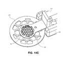
- FIGS. 14A-14Dillustrate an exemplary embodiment of minimal and moderate bodies, which can be incorporated into the assembly from FIGS. 7-13 .
- Minimal body 224includes recess 225 formed therein such that when moderate body and minimal body are moved towards one another, they form a nest in which the inlay is retained (see FIG. 14D ).
- the recesshas a generally circular configuration (similar to the general configuration of minimal body 224 ), but other configurations may be suitable.
- Recess 225is adapted to accommodate the corneal implant within the recess.
- Recess 225is also sized to prevent inlay 140 (see FIGS. 14B-14D ) from being compressed between the minimal and moderate bodies while being shipped or stored (see FIG. 14D ).
- the corneal implantis therefore maintained in substantially unstressed, or non-deformed, configuration.
- the inlayhas a defined curvature, it may be preferred to not allow the inlay to be distorted during shipping and/or storage, and the recess (and thus the nest) can be sized to help prevent it from being distorted.
- the recess formed in the minimal bodyallows for easy containment without excess force being applied to the inlay.
- the nest formed by the moderate and minimal bodiesprevents compression and/or damage to the inlay while acting as a storage compartment.
- the recess sizeis larger than the inlay size.
- the diameter of the recess (“dr”)is greater than the diameter of the inlay (“di”).
- the diameter of the moderate body (“dM”)is greater than the diameter of the recess (“dr”) formed in the minimal body (see FIG. 14D ).
- the diameter of the minimal body (“dm”)is greater than the diameter of the moderate body (“dM”).
- the depth of the recessis greater than the material thickness of the inlay, but is preferably slightly less than the height of the corneal implant in a non-stressed configuration. This ensures that at least a portion of the corneal implant is maintained in contact with both the moderate body and the minimal body. If at least a portion of the corneal implant is not in contact with the moderate body, the corneal implant can remain adhered to the minimal body rather than the moderate body when the moderate and minimal bodies are moved away from one another.
- the material thickness of the corneal implantis about 38.1 microns
- the overall height of the implant in a non-stressed configurationis about 152.4 microns
- the depth of the recessis between about 63.5 microns and about 114.3 microns.
- moderate body 222is secured to first portion 218
- minimal body 224is secured to second portion 220 .
- the systemis used in the same manner as the embodiment in FIGS. 7-13 .
- the moderate bodyis stainless steel. In some embodiments it can be about 0.1 mm thick. As shown in the figures, the plurality of openings in the moderate body have general hexagon configurations. In some exemplary embodiments the dimension from a first side of the hexagon to a second side that is parallel to the first side (i.e., double the hexagon's apothem) of at least a substantial number of the hexagon shapes is about 0.35 mm. In some embodiments that dimension could be between about 0.02 mm to about 0.12 mm.
- the distance between hexagonsis about 0.05 mm, although this distance could be between about 0.01 mm and about 0.25 mm.
- the diameter of the moderate bodycan be about 3 mm, but in some embodiments it is between about 0.25 mm and about 13 mm.
- the minimal bodyis stainless steel, and is about 0.2 mm thick, except in the recess section.
- the openings in the minimal bodyeach have general hexagon configurations.
- the dimension from a first side of the hexagon to a second side that is parallel to the first side (i.e., double the hexagon's apothem) of at least a substantial number of the hexagon shapesis about 1 mm. In some embodiments that dimension could be between about 0.1 mm to about 3 mm.
- the distance between hexagons(i.e., the distance from a first side of a first hexagon to a first side of a second hexagon, wherein the sides are parallel to one another and the hexagons are directly adjacent to one another) can be about 0.2 mm, although this distance could be between about 0.02 mm to about 0.12 mm.
- the diameter of the minimal bodycan be about 6.5 mm, but in some embodiments it is between about 3 mm and about 13 mm.
- the diameter of the minimal bodyis at least about 2 times the diameter of the moderate body. In some embodiments the diameter of the minimal body is at least about 1.5 times the diameter of the moderate body. In some embodiments the size of the plurality of hexagons in the minimal body is at least about 2 times the size of the plurality of hexagons in the moderate body. In some embodiments they could be at least about 3 times, or at least about 4 times.
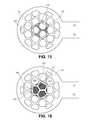
- FIGS. 15-18illustrate additional views illustrating the relative sizes and dimensions of the mesh bodies and a corneal inlay.
- the inlayhas a diameter of about 2 mm.
- FIG. 15is a top view illustrating minimal mesh body 224 , recess 225 formed in minimal mesh body, periphery of inlay 140 , and the surface area 240 (shown in hash lines) of minimal body 224 that overlaps with the inlay when the inlay is positioned in recess 225 .
- surface area 240 of minimal body 224 that overlaps with the inlayis about 0.9 mm 2 .
- the perimeter of the inlay that overlaps the minimal bodyis about 9 mm.
- 16illustrates minimal mesh body 224 and periphery of inlay 140 , and the surface area 242 (shown in hash lines) of openings 244 (only three openings 244 labeled) that overlaps the inlay when the inlay is in the recess.
- the surface area 242is about 2 mm 2 .
- FIG. 17illustrates moderate mesh body 222 and the periphery of inlay 140 disposed thereon.
- Surface area 250 of moderate body 222is the surface area of the moderate body that overlaps the inlay, at least a portion of which is in contact with the inlay, when the inlay is positioned in the nest. In this particular embodiment surface area is about 0.75 mm 2 .
- the perimeter of the inlayis about 26 mm.
- FIG. 18illustrates moderate body 222 , periphery of inlay 140 , and the surface area 254 (shown in hash lines) of openings 252 (only three openings 252 are labeled) that overlap the inlay.
- Surface area 254is about 2.3 mm 2 .
- the moderate body and the minimal bodyeach have one or more openings, or apertures, extending through the bodies.
- the ratio of the moderate aperture perimeter (or sum of the aperture perimeters if more than one aperture) to the moderate aperture area (or sum of the apertures areas if more than one aperture)is greater than the ratio of the minimal aperture perimeter (or sum of the aperture perimeters if more than one aperture) to the minimal aperture area (or sum of the aperture areas if more than one aperture).
- the greater ratioresults in greater forces being applied to the corneal implant from the moderate body than the minimal body, and thus provides the moderate body with a higher affinity for the corneal implant than the minimal body. When the moderate and minimal bodies are moved apart relative to one another, the greater forces applied to the implant will cause the implant to remain adhered to the moderate body rather than the minimal body.
- the sum of the perimeters of the apertures in the moderate body that overlap the implantwere determined to be about 1.03 in, while the sum of the aperture areas that overlap the implant were determined to be about 0.0012 in 2 .
- the ratio of perimeter to area for this particular moderate bodywas about 858 in ⁇ 1 .
- the sum of the perimeters of the apertures in the minimal body that overlap the implantwere determined to be about 0.365 in, while the sum of the aperture areas that overlap the implant were determined to be about 0.0014 in 2 .
- the ratio of perimeter to area for this particular moderate bodywas about 260 in ⁇ 1 . The ratio is therefore greater for the moderate body than for the minimal body.
- FIG. 19is a partial exploded view of an exemplary corneal implant storage and positioning device.
- Positioning device 310generally includes a handle assembly 312 that includes the moderate body, support assembly 314 that includes the minimal body, and actuator assembly 316 that is adapted to actuate, or move, support assembly 314 with respect to handle assembly 312 . Due to the inlay's greater affinity for the moderate body, the inlay will adhere to the moderate body when the support assembly 314 is actuated.
- Actuator assembly 316includes push rod 320 coupled to button 321 , and spring 322 .
- Handle assembly 312includes handle 324 coupled to distal portion 326 , which includes the moderate body.
- the distal end of spring 322is secured within the internal channel within handle 312
- the proximal end of spring 322is secured to the distal end of button 321 .
- Push rod 320is configured to be disposed within the internal lumen of spring 322 . As shown in more detail in FIGS. 20A-20C , the distal end of push rod 320 includes bore 328 therethrough, adapted to receive dowel 318 therein.
- dowel 318is advanced through bore 328 .
- Dowel 318both prevents push rod 320 from retracting proximally within handle assembly 312 , but it also provides base assembly 314 with a surface to engage in order to secure support assembly 314 in place relative to handle assembly 312 , as shown in FIG. 20C .
- the devicealso includes rod 330 , which helps secure support assembly 314 in place relative to handle assembly 312 (see FIG. 20C ), but allows support assembly 314 to rotate around rod 330 when the actuator is actuated.
- Dowel 318is also involved in the actuation of the support assembly.
- Actuating button 321causes push rod 320 , and thus dowel 318 , to be advanced distally within handle assembly 312 .
- Thiscauses dowel 318 to apply a generally distally directed force to support assembly 314 , which causes dowel 318 to push down on support assembly 314 .
- support assembly 314will begin to rotate around rod 330 , causing minimal body mesh 338 to move away from moderate mesh body 334 . Further rotation of support assembly 314 will free support assembly 314 from rod 330 , allowing support assembly 314 to be completely disengaged from handle assembly 312 .
- the corneal implantOnce disengaged, the corneal implant will remain adhered to moderate body 334 and is ready for use, such as delivery into or onto corneal tissue.
- the usercan release button 321 , and spring 322 causes actuator 316 to return to an at-rest, or non-actuated, position relative to handle assembly 312 .
- support assembly 314rotates with respect to handle assembly 312 in only one direction, which prevents torqueing.
- FIG. 21is a partial exploded view of handle assembly 312 shown in FIG. 17 (actuator and base assembly not shown).
- Assembly 312includes handle 324 , distal tip portion 342 , dowel 318 , applicator base 336 , and applicator 334 .
- Handle 324is secured to distal tip portion 342 , and the distal end of distal tip portion 342 is disposed within a bore in applicator base 336 .
- Applicator 334is secured to applicator base 336 .
- FIG. 22shows the assembled view from FIG. 21 .
- FIGS. 23A-23Dillustrate alternative views of the assembly of applicator base 336 , applicator 334 , and rod 330 .
- FIG. 23Ais an exploded perspective bottom view.
- FIG. 23Bis a perspective top view illustrating how rod 330 is disposed within applicator base 336 .
- FIG. 23Cis a bottom view showing applicator 334 secured to applicator base 336 and a plurality of attachment points 350 for securing applicator 334 to applicator base 336 .
- FIG. 23Dis a front view showing applicator 34 secured to applicator base 336 , and rod 330 disposed within applicator base 336 .
- Applicator 334 and applicator base 336can be secured together by any suitable technique.
- applicator 334is welded to base 336 , such as by resistance welding or laser welding.
- Applicator 334includes the moderate mesh body.
- FIGS. 24A-24Iillustrate a variety of views of a particular embodiment of applicator base 336 described above.
- the internal bore through which the actuator extendscan be seen in the sectional side view of FIG. 24D .
- the dimensions indicated in the figuresare merely exemplary to this particular embodiment and are not limiting.
- FIGS. 25A-25Cillustrate exemplary dimensions for applicator 334 , including the mesh dimensions, described above. For example, dimensions of the mesh that contribute to implant preference to adhere to the moderate body over the minimal body are shown.
- FIG. 25 Ais a top view.
- FIG. 25Bis a side view.
- FIG. 25Cis a detailed view of section A from FIG. 25A .
- FIGS. 26A-26Dillustrate support assembly 314 from FIG. 17 , which includes support base 340 secured to implant support 338 .
- Support base 340 and implant support 338are secured to one another similarly to the applicator base and the applicator described above.
- FIG. 26Ais an exploded view
- FIG. 26Bis an assembled view
- FIG. 26Cis a top view
- FIG. 26Dis a detailed view C from FIG. 26A of applicator 338 showing recess 360 defined by recess sidewalls 356 and recess base surface 358 .
- the implantis configured and sized to be disposed within the recess such that it is positioned between the minimal and moderate meshes prior to removal of the minimal body.
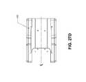
- FIGS. 27A-27Eillustrate front, sectional side, side, and top views of support base 340 .
- FIGS. 28A-28Dillustrate views of the support 338 .
- FIG. 28Billustrates section A-A shown in FIG. 28A .
- FIG. 28Cshows detail B from FIG. 28B
- FIG. 28Dshows detail C from FIG. 10A .
- Recess 360is formed in a top portion of the support 338 .
- Mesh apertures 364are defined by body 362 , illustrated in FIGS. 28B and 28C . The dimensions shown are exemplary and not intended to be limiting.
- the mesh apertures of the minimal bodyare larger than the mesh apertures of the moderate body, which is one of the contributing factors for why in this particular embodiment the implant preferentially adheres to the moderate body.
- the recess in the minimal mesh bodyshould be sized to prevent forces, or a substantial amount of forces, from being applied to the corneal implant while it is positioned in the nest between the moderate and minimal bodies prior to use.
- the mesh apertures and the recesscan be created by any suitable technique, such as chemical etching, laser cutting, micro water jet cutting, etc. In some instances chemical etching provides for a cleaner cut and does not require as much post-manufacture processing of the body.
- the mesh aperturescan be created from only one side, or in some embodiments half of the thickness of the aperture is created from one side, while the other half of the aperture is created from the other side.
- the recessis etched from one side, while the mesh apertures are created in the other side. Any combination or variation on these techniques can be used.
- the recessis created by plunge electrical discharge machining (“EDM”).
- the net forces acting on the corneal implantare greater from the moderate mesh body than from the minimal mesh body.
- the polarity of wateris an important factor when the corneal implant is formed of a hydrophilic material because in these instances the implant has properties like water and as such behaves like water.
- the dimensions of the mesh, configuration of the mesh, mesh body, and other factorscan be modified to alter the relative affinities.
- the minimal mesh body diameteris larger than the moderate mesh body diameter (both are shown to have a generally circular configuration).
- the minimal body diameterdue to its larger size, acts like a bumper, protecting the entire distal region of the apparatus during storage and use prior to actuation of the actuator.
- the minimal body thicknessis about twice as thick as the moderate body.
- the moderate body diameteris larger than the recess, while the minimal body diameter is larger than the moderate body diameter.
- the moderate mesh bodycan be sized such that it does not interfere with the visualization of the pupil.
- the moderate mesh body portionis sized to allow the physician to be able to see the pupil during the delivery of the implant on corneal tissue. Starting with this constraint, the size of the other components can then be determined.
- the use of “diameter” hereinis not to suggest that the mesh body outer surfaces are perfectly circular or are circular at all.
- the two mesh portionscould be square or rectangular-shaped, with the width and length of the minimal mesh portion larger than the width and length of the moderate mesh portion.
- the implant's affinity for the moderate bodyis described as largely due to the size and configuration of the moderate mesh body relative to the minimal body, there are many ways to establish and control the implant's affinity for a given body. In some embodiments this can be accomplished by using a moderate body that is different than the minimal body. In some embodiments a finish could be applied to one or more of the surfaces of the moderate and minimal bodies. The finish can be different on the moderate and the minimal body to control the preferential adhesion. In some embodiments the moderate body has a better finish than the minimal body. In some embodiments the minimal body has a matte finish on it.
- One or more components of the devices described hereincan be a stainless steel or titanium.
- applicator base 36 and applicator 34can both be stainless steel, one can be titanium while the other is stainless steel, or both can be titanium.
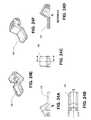
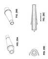
- FIGS. 29A-29Dillustrate views of distal tip 342 from the handle assembly described above.
- FIG. 29Ais a view looking from the proximal end to the distal end
- FIG. 29Bis a view from the distal end to the proximal end
- FIG. 29Cis a sectional side view
- FIG. 29Dis a front view.
- the distal tipis secured to the handle, and the distal end of it is disposed in the applicator base 336 .
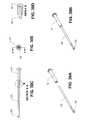
- FIGS. 30A-30Eillustrate in detail actuator assembly 316 from FIG. 19 .
- the actuatorincludes button 321 , push rod 320 , and bore 328 at the distal end of push rod 320 .
- FIG. 30Ais an exploded view
- FIG. 30Bis an assembly view
- FIG. 30Cis a side sectional view of section A-A shown in FIG. 30E
- FIG. 30Dis a detail view of section B shown in FIG. 30C .
- FIGS. 31A-31Dillustrate detailed views of button 321 .
- FIGS. 32A-32Dillustrate detailed views of push rod 320 , including bore 328 .
- FIGS. 33A-33Dillustrate detailed views of handle 324 .
- FIGS. 34A and 34Billustrate detailed views of spring 322 .
- FIGS. 35A and 35Billustrate detailed viewed of dowel 18 .
- the implantcan be used right away or it can be stored in packaging for any suitable period of time.
- the corneal implantis made of a hydrogel material, it is important to keep the implant adequately hydrated during storage.
- Embodiments hereindescribe both a moderate body and a minimal body.
- the apparatus or its method of useneed not include the minimal body.
- the corneal implantis not positioned within a corneal nest defined by the moderate and minimal bodies.
- the implanttherefore need not be packaged with the moderate body.
- itcan be packaged in a separate packaging.
- the moderate bodycan utilize its preferential adhesion for the implant as set forth above to retrieve, or pick up, the corneal implant from its packaging. This can eliminate restrictions on how the cornel implant needs to be packaged.
- the implantcan be stored in a vial, free-floating in a storage medium.
- the moderate bodywhich can be coupled to a handle, is positioned adjacent the implant in its storage medium, such as by scooping up the corneal implant into a position adjacent the apertures therein. Due to its preferential adhesion adaptation, the corneal implant will preferentially adhere to the moderate body. Once it has adhered to the moderate body, the implant is ready to be deposited onto the cornea as set forth above by relying on the moderate body's adaptation to allow the implant to preferentially adhere to the corneal tissue rather than the moderate body.
Landscapes
- Health & Medical Sciences (AREA)
- Life Sciences & Earth Sciences (AREA)
- Engineering & Computer Science (AREA)
- Biomedical Technology (AREA)
- Veterinary Medicine (AREA)
- Public Health (AREA)
- General Health & Medical Sciences (AREA)
- Heart & Thoracic Surgery (AREA)
- Animal Behavior & Ethology (AREA)
- Transplantation (AREA)
- Vascular Medicine (AREA)
- Oral & Maxillofacial Surgery (AREA)
- Cardiology (AREA)
- Ophthalmology & Optometry (AREA)
- Surgery (AREA)
- Nuclear Medicine, Radiotherapy & Molecular Imaging (AREA)
- Medical Informatics (AREA)
- Molecular Biology (AREA)
- Prostheses (AREA)
Abstract
Description
Claims (12)
Priority Applications (2)
| Application Number | Priority Date | Filing Date | Title |
|---|---|---|---|
| US13/657,650US8668735B2 (en) | 2000-09-12 | 2012-10-22 | Corneal implant storage and delivery devices |
| US14/160,438US9889000B2 (en) | 2000-09-12 | 2014-01-21 | Corneal implant applicators |
Applications Claiming Priority (11)
| Application Number | Priority Date | Filing Date | Title |
|---|---|---|---|
| US09/660,371US6543610B1 (en) | 2000-09-12 | 2000-09-12 | System for packaging and handling an implant and method of use |
| US09/843,547US6581993B2 (en) | 2000-09-12 | 2001-04-26 | System for packaging and handling an implant and method of use |
| US10/463,091US6893461B2 (en) | 2000-09-12 | 2003-06-17 | System for packaging and handling an implant and method of use |
| US11/054,639US7128351B2 (en) | 2000-09-12 | 2005-02-09 | System for packaging and handling an implant and method of use |
| US11/422,815US7992906B2 (en) | 2000-09-12 | 2006-06-07 | System for packaging and handling an implant and method of use |
| US13/206,200US20110290681A1 (en) | 2000-09-12 | 2011-08-09 | System for Packaging and Handling an Implant and Method of Use |
| US201161550185P | 2011-10-21 | 2011-10-21 | |
| US201261606674P | 2012-03-05 | 2012-03-05 | |
| US13/443,696US9005280B2 (en) | 2000-09-12 | 2012-04-10 | System for packaging and handling an implant and method of use |
| US201261679482P | 2012-08-03 | 2012-08-03 | |
| US13/657,650US8668735B2 (en) | 2000-09-12 | 2012-10-22 | Corneal implant storage and delivery devices |
Related Parent Applications (1)
| Application Number | Title | Priority Date | Filing Date |
|---|---|---|---|
| US13/443,696Continuation-In-PartUS9005280B2 (en) | 2000-09-12 | 2012-04-10 | System for packaging and handling an implant and method of use |
Related Child Applications (1)
| Application Number | Title | Priority Date | Filing Date |
|---|---|---|---|
| US14/160,438ContinuationUS9889000B2 (en) | 2000-09-12 | 2014-01-21 | Corneal implant applicators |
Publications (2)
| Publication Number | Publication Date |
|---|---|
| US20130123916A1 US20130123916A1 (en) | 2013-05-16 |
| US8668735B2true US8668735B2 (en) | 2014-03-11 |
Family
ID=48281364
Family Applications (2)
| Application Number | Title | Priority Date | Filing Date |
|---|---|---|---|
| US13/657,650Expired - Fee RelatedUS8668735B2 (en) | 2000-09-12 | 2012-10-22 | Corneal implant storage and delivery devices |
| US14/160,438Expired - Fee RelatedUS9889000B2 (en) | 2000-09-12 | 2014-01-21 | Corneal implant applicators |
Family Applications After (1)
| Application Number | Title | Priority Date | Filing Date |
|---|---|---|---|
| US14/160,438Expired - Fee RelatedUS9889000B2 (en) | 2000-09-12 | 2014-01-21 | Corneal implant applicators |
Country Status (1)
| Country | Link |
|---|---|
| US (2) | US8668735B2 (en) |
Cited By (12)
| Publication number | Priority date | Publication date | Assignee | Title |
|---|---|---|---|---|
| US20050113844A1 (en)* | 2000-09-12 | 2005-05-26 | Alok Nigam | System for packaging and handling an implant and method of use |
| US9345569B2 (en) | 2011-10-21 | 2016-05-24 | Revision Optics, Inc. | Corneal implant storage and delivery devices |
| US9539143B2 (en) | 2008-04-04 | 2017-01-10 | Revision Optics, Inc. | Methods of correcting vision |
| US9877823B2 (en) | 2007-03-28 | 2018-01-30 | Revision Optics, Inc. | Corneal implant retaining devices and methods of use |
| US9889000B2 (en) | 2000-09-12 | 2018-02-13 | Revision Optics, Inc. | Corneal implant applicators |
| US10092393B2 (en) | 2013-03-14 | 2018-10-09 | Allotex, Inc. | Corneal implant systems and methods |
| US10449090B2 (en) | 2015-07-31 | 2019-10-22 | Allotex, Inc. | Corneal implant systems and methods |
| US10555805B2 (en) | 2006-02-24 | 2020-02-11 | Rvo 2.0, Inc. | Anterior corneal shapes and methods of providing the shapes |
| US10583041B2 (en) | 2015-03-12 | 2020-03-10 | RVO 2.0 Inc. | Methods of correcting vision |
| US10835371B2 (en) | 2004-04-30 | 2020-11-17 | Rvo 2.0, Inc. | Small diameter corneal inlay methods |
| US10918474B2 (en) | 2017-09-11 | 2021-02-16 | Industrial Technology Research Institute | Implanting device |
| US11678973B2 (en)* | 2020-05-27 | 2023-06-20 | EyeYon Medical Ltd. | Corneal implant injector system |
Families Citing this family (9)
| Publication number | Priority date | Publication date | Assignee | Title |
|---|---|---|---|---|
| US9549848B2 (en) | 2007-03-28 | 2017-01-24 | Revision Optics, Inc. | Corneal implant inserters and methods of use |
| JP2011516180A (en) | 2008-04-04 | 2011-05-26 | レヴィジオン・オプティックス・インコーポレーテッド | Corneal inlay design and method for correcting vision |
| US9107728B2 (en)* | 2012-09-23 | 2015-08-18 | Mark Philip Breazzano | Eyeball stabilizing apparatus and method of use |
| IL230567A0 (en) | 2014-01-21 | 2014-04-30 | E K D D S Ltd | Method and appartus for improved endothelial implatation |
| US11540915B2 (en) | 2014-01-21 | 2023-01-03 | E.K.—D.D.S. Ltd. | Handheld implantation devices for implantation or retinal tissue implant |
| CN107249514A (en)* | 2014-08-19 | 2017-10-13 | 修正光学公司 | Corneal Implant Storage, Packaging and Delivery Devices |
| JP2017533807A (en)* | 2014-11-06 | 2017-11-16 | オフタ イノベーションズ インコーポレイテッド | Corneal inlay for beauty and transplantation method thereof |
| WO2019118790A1 (en)* | 2017-12-13 | 2019-06-20 | Allotex, Inc. | Corneal implant systems and methods |
| CN214549463U (en)* | 2020-09-09 | 2021-11-02 | 京东方科技集团股份有限公司 | a transplant device |
Citations (349)
| Publication number | Priority date | Publication date | Assignee | Title |
|---|---|---|---|---|
| US2714721A (en) | 1953-01-23 | 1955-08-09 | Jr William Stone | Artificial corneal implants |
| US3091328A (en)* | 1961-03-02 | 1963-05-28 | Priscilla A Leonardos | Contact lens remover and carrier |
| US3168100A (en) | 1962-12-07 | 1965-02-02 | Alvido R Rich | Contact lens dipper assembly |
| US3343657A (en) | 1966-09-02 | 1967-09-26 | Reuben F Speshyock | Contact lens conditioning facility |
| US3379200A (en) | 1965-10-24 | 1968-04-23 | Ruth M. Pennell | Lens containtr |
| US3482906A (en) | 1965-10-04 | 1969-12-09 | David Volk | Aspheric corneal contact lens series |
| US3743337A (en) | 1971-07-26 | 1973-07-03 | E Crary | Contact lens inserter |
| US3770113A (en) | 1972-03-03 | 1973-11-06 | Mcd Corp | Contact lens holder |
| US3879076A (en) | 1973-12-27 | 1975-04-22 | Robert O Barnett | Method and apparatus for applying and removing a soft contact lens |
| US3950315A (en) | 1971-06-11 | 1976-04-13 | E. I. Du Pont De Nemours And Company | Contact lens having an optimum combination of properties |
| US3996627A (en) | 1975-09-22 | 1976-12-14 | American Optical Corporation | Artificial intraocular lens |
| US4030480A (en) | 1976-05-13 | 1977-06-21 | Ernst Jochen Meyer | Ocular decompression process |
| US4037604A (en) | 1976-01-05 | 1977-07-26 | Newkirk John B | Artifical biological drainage device |
| US4039827A (en) | 1976-08-26 | 1977-08-02 | American Optical Corporation | Method for marking intraocular lenses |
| US4065816A (en) | 1975-05-22 | 1978-01-03 | Philip Nicholas Sawyer | Surgical method of using a sterile packaged prosthesis |
| US4071272A (en) | 1976-09-27 | 1978-01-31 | Drdlik Frank J | Contact lens applicator |
| US4093291A (en)* | 1977-08-17 | 1978-06-06 | Schurgin Herbert L | Contact lens application and removal instrument |
| US4136406A (en) | 1977-07-20 | 1979-01-30 | Norris John W | Intraocular lens with attached disposable instrument |
| US4157718A (en) | 1977-08-31 | 1979-06-12 | The United States Of America As Represented By The Administrator Of The National Aeronautics And Space Administration | Intra-ocular pressure normalization technique and equipment |
| US4184491A (en) | 1977-08-31 | 1980-01-22 | The United States Of America As Represented By The Administrator Of The National Aeronautics And Space Administration | Intra-ocular pressure normalization technique and equipment |
| US4194814A (en) | 1977-11-10 | 1980-03-25 | Bausch & Lomb Incorporated | Transparent opthalmic lens having engraved surface indicia |
| US4238524A (en) | 1978-03-06 | 1980-12-09 | American Optical Corporation | Process for identification marking clear plastic articles |
| US4257521A (en)* | 1979-11-16 | 1981-03-24 | Stanley Poler | Packaging means for an intraocular lens |
| US4268133A (en) | 1978-07-14 | 1981-05-19 | Bausch & Lomb Incorporated | Preferential orientation of contact lenses |
| US4326306A (en) | 1980-12-16 | 1982-04-27 | Lynell Medical Technology, Inc. | Intraocular lens and manipulating tool therefor |
| US4357940A (en) | 1979-12-13 | 1982-11-09 | Detroit Neurosurgical Foundation | Tissue pneumatic separator structure |
| US4392569A (en) | 1979-06-06 | 1983-07-12 | Shoup Leo E | Soft contact lens asepticizing case |
| DE3208729A1 (en) | 1982-03-11 | 1983-09-22 | Jörg Dr.med. 4630 Bochum Krumeich | Plastic lens |
| US4418991A (en) | 1979-09-24 | 1983-12-06 | Breger Joseph L | Presbyopic contact lens |
| US4423809A (en)* | 1982-02-05 | 1984-01-03 | Staar Surgical Company, Inc. | Packaging system for intraocular lens structures |
| US4428746A (en) | 1981-07-29 | 1984-01-31 | Antonio Mendez | Glaucoma treatment device |
| US4452235A (en) | 1982-01-04 | 1984-06-05 | Reynolds Alvin E | Method for corneal curvature adjustment |
| US4466705A (en) | 1982-09-30 | 1984-08-21 | Michelson Paul E | Fluid lens |
| US4490860A (en) | 1982-01-18 | 1985-01-01 | Ioptex Inc. | Intraocular lens apparatus and method for implantation of same |
| US4504982A (en) | 1982-08-05 | 1985-03-19 | Optical Radiation Corporation | Aspheric intraocular lens |
| US4521210A (en) | 1982-12-27 | 1985-06-04 | Wong Vernon G | Eye implant for relieving glaucoma, and device and method for use therewith |
| US4525044A (en) | 1983-05-05 | 1985-06-25 | Bauman Robert C | Soft contact lens with surface identification and method of using same |
| US4545478A (en) | 1982-07-08 | 1985-10-08 | Fred Waldman | Hard contact lens suction cups and method for their production |
| US4554115A (en) | 1983-08-30 | 1985-11-19 | Neefe Charles W | Method of controlling the convex curve of soft lenses |
| US4554918A (en) | 1982-07-28 | 1985-11-26 | White Thomas C | Ocular pressure relief device |
| US4565198A (en) | 1983-12-27 | 1986-01-21 | Barnes-Hind, Inc. | Method for altering the curvature of the cornea |
| US4580882A (en) | 1983-04-21 | 1986-04-08 | Benjamin Nuchman | Continuously variable contact lens |
| US4586929A (en) | 1984-04-06 | 1986-05-06 | Binder Perry S | Hydrogel keratoprosthesis |
| US4604087A (en) | 1985-02-26 | 1986-08-05 | Joseph Neil H | Aqueous humor drainage device |
| US4607617A (en) | 1980-08-05 | 1986-08-26 | Choyce David P | Apparatus and method for improving eyesight |
| US4616910A (en) | 1983-03-01 | 1986-10-14 | Klein Robert E | Visual indicator on soft contact lenses |
| US4618227A (en) | 1983-10-07 | 1986-10-21 | Vistakon, Inc. | Soft contact lens |
| US4619256A (en) | 1982-09-08 | 1986-10-28 | Gerald Horn | Intraocular lens inserting assembly |
| US4624669A (en) | 1984-09-26 | 1986-11-25 | Surgidev Corporation | Corneal inlay with holes |
| US4624664A (en) | 1985-07-22 | 1986-11-25 | Travenol European Research And Development Centre (Teradec) | Antibacterial closure system |
| US4640595A (en) | 1984-05-02 | 1987-02-03 | David Volk | Aspheric contact lens |
| US4646720A (en) | 1985-03-12 | 1987-03-03 | Peyman Gholam A | Optical assembly permanently attached to the cornea |
| US4655774A (en) | 1986-01-03 | 1987-04-07 | Choyce D Peter | Intra-corneal implant for correction of aniridia |
| US4662370A (en) | 1984-09-13 | 1987-05-05 | Carl-Zeiss-Stiftung | Apparatus for performing lamellar refractive corneal surgery |
| US4663358A (en) | 1985-05-01 | 1987-05-05 | Biomaterials Universe, Inc. | Porous and transparent poly(vinyl alcohol) gel and method of manufacturing the same |
| US4671276A (en) | 1982-01-04 | 1987-06-09 | Kera Associates | Apparatus for corneal curvature adjustment |
| US4676792A (en) | 1986-08-26 | 1987-06-30 | Donald Praeger | Method and artificial intraocular lens device for the phakic treatment of myopia |
| US4697697A (en) | 1986-08-18 | 1987-10-06 | Coopervision, Inc. | Method and apparatus for packaging an intraocular lens |
| US4702244A (en) | 1982-02-05 | 1987-10-27 | Staar Surgical Company | Surgical device for implantation of a deformable intraocular lens |
| US4709697A (en) | 1980-12-09 | 1987-12-01 | Joseph J. Berke | Tissue pneumatic separator structure and method |
| US4721124A (en) | 1983-12-01 | 1988-01-26 | Barry Tuerkheimer | Optometric soft and rigid contact lens cleaning and storage system |
| US4726367A (en) | 1985-08-19 | 1988-02-23 | Shoemaker David W | Surgical instrument for implanting an intraocular lens |
| US4750901A (en) | 1986-03-07 | 1988-06-14 | Molteno Anthony C B | Implant for drainage of aqueous humour |
| US4762496A (en) | 1987-02-13 | 1988-08-09 | William F. Maloney | Ophthalmologic lens phantom system |
| US4766895A (en) | 1982-01-04 | 1988-08-30 | Kera Corneal Devices, Inc. | Apparatus for corneal curvature adjustment |
| US4769033A (en) | 1987-07-02 | 1988-09-06 | Nordan Lee T | Intraocular multifocal lens |
| US4772283A (en) | 1986-05-16 | 1988-09-20 | White Thomas C | Corneal implant |
| US4778462A (en) | 1987-08-24 | 1988-10-18 | Grendahl Dennis T | Multiple element zone of focus artificial lens |
| US4798609A (en) | 1987-08-24 | 1989-01-17 | Grendahl Dennis T | Radially segmented zone of focus artificial lens |
| US4806382A (en) | 1987-04-10 | 1989-02-21 | University Of Florida | Ocular implants and methods for their manufacture |
| EP0308077A2 (en) | 1987-09-14 | 1989-03-22 | Nestle S.A. | Synthetic intracorneal lens |
| US4836201A (en) | 1988-03-24 | 1989-06-06 | Patton Medical Technologies, Inc. | "Envelope" apparatus for inserting intra-ocular lens into the eye |
| US4840175A (en) | 1986-12-24 | 1989-06-20 | Peyman Gholam A | Method for modifying corneal curvature |
| US4842599A (en) | 1986-10-28 | 1989-06-27 | Ann M. Bronstein | Prosthetic cornea and method of implantation therefor |
| US4844242A (en)* | 1987-09-02 | 1989-07-04 | The Johns Hopkins University | Cornea retainer |
| US4851003A (en) | 1988-01-05 | 1989-07-25 | Lindstrom Richard L | Corneal implant lens with fixation holes |
| US4860885A (en) | 1988-04-29 | 1989-08-29 | Allergan, Inc. | Lens storage system |
| US4886488A (en) | 1987-08-06 | 1989-12-12 | White Thomas C | Glaucoma drainage the lacrimal system and method |
| US4888016A (en) | 1988-02-10 | 1989-12-19 | Langerman David W | "Spare parts" for use in ophthalmic surgical procedures |
| US4897981A (en) | 1986-12-24 | 1990-02-06 | Alcon Laboratories, Inc. | Method of packaging intraocular lenses and contact lenses |
| US4911715A (en) | 1989-06-05 | 1990-03-27 | Kelman Charles D | Overlapping two piece intraocular lens |
| US4919130A (en) | 1986-11-07 | 1990-04-24 | Nestle S.A. | Tool for inserting compressible intraocular lenses into the eye and method |
| US4923467A (en) | 1988-03-02 | 1990-05-08 | Thompson Keith P | Apparatus and process for application and adjustable reprofiling of synthetic lenticules for vision correction |
| US4934363A (en) | 1987-12-15 | 1990-06-19 | Iolab Corporation | Lens insertion instrument |
| US4936825A (en) | 1988-04-11 | 1990-06-26 | Ungerleider Bruce A | Method for reducing intraocular pressure caused by glaucoma |
| US4946436A (en) | 1989-11-17 | 1990-08-07 | Smith Stewart G | Pressure-relieving device and process for implanting |
| US4955903A (en) | 1986-07-22 | 1990-09-11 | Ceskoslovenska Akademie Ved | Soft intracameral lens |
| US4968296A (en) | 1989-12-20 | 1990-11-06 | Robert Ritch | Transscleral drainage implant device for the treatment of glaucoma |
| US4971732A (en) | 1984-06-28 | 1990-11-20 | Ceskoslovenska Academie Ved | Method of molding an intraocular lens |
| US4976719A (en) | 1988-11-21 | 1990-12-11 | Siepser Steven B | Device used to change corneal curvature |
| EP0420549A2 (en) | 1989-09-25 | 1991-04-03 | HYMEDIX International, Inc. | Corneal lens implant |
| US5019098A (en) | 1989-05-19 | 1991-05-28 | Essilor International Cie Generale D'optique | Sight-correcting optical component such as an intra-ocular implant or contact lens |
| US5019084A (en) | 1986-08-06 | 1991-05-28 | Minnesota Mining And Manufacturing Company | Corneal holder |
| US5022414A (en) | 1979-12-13 | 1991-06-11 | Joseph J. Berke | Tissue separator method |
| US5030230A (en) | 1986-05-16 | 1991-07-09 | Great Plains Eye Clinic, Ltd. | Corneal implant |
| US5041081A (en) | 1990-05-18 | 1991-08-20 | Odrich Ronald B | Ocular implant for controlling glaucoma |
| US5063942A (en) | 1989-12-14 | 1991-11-12 | Corneal Contouring, Inc. | Method for surgically re-profiling the cornea |
| US5071276A (en) | 1991-01-04 | 1991-12-10 | Abbott Laboratories | Contact lens cleaning system |
| US5073163A (en) | 1990-01-29 | 1991-12-17 | Lippman Myron E | Apparatus for treating glaucoma |
| US5092837A (en) | 1989-12-20 | 1992-03-03 | Robert Ritch | Method for the treatment of glaucoma |
| US5098444A (en) | 1990-03-16 | 1992-03-24 | Feaster Fred T | Epiphakic intraocular lens and process of implantation |
| US5108428A (en) | 1988-03-02 | 1992-04-28 | Minnesota Mining And Manufacturing Company | Corneal implants and manufacture and use thereof |
| US5112350A (en) | 1986-10-16 | 1992-05-12 | Cbs Lens, A California General Partnership | Method for locating on a cornea an artificial lens fabricated from a collagen-hydrogel for promoting epithelial cell growth and regeneration of the stroma |
| WO1992008423A1 (en) | 1989-01-23 | 1992-05-29 | Cumming J Stuart | Intraocular lens insertion device |
| US5123905A (en) | 1991-06-07 | 1992-06-23 | Kelman Charles D | Intraocular lens injector |
| US5139518A (en) | 1986-05-16 | 1992-08-18 | White Thomas C | Methods employed in replacement of the corneal endothelium |
| US5171213A (en) | 1991-08-14 | 1992-12-15 | Price Jr Francis W | Technique for fistulization of the eye and an eye filtration prosthesis useful therefor |
| US5173723A (en) | 1990-10-02 | 1992-12-22 | Volk Donald A | Aspheric ophthalmic accommodating lens design for intraocular lens and contact lens |
| US5178604A (en) | 1990-05-31 | 1993-01-12 | Iovision, Inc. | Glaucoma implant |
| US5181053A (en) | 1990-05-10 | 1993-01-19 | Contact Lens Corporation Of America | Multi-focal contact lens |
| US5180362A (en) | 1990-04-03 | 1993-01-19 | Worst J G F | Gonio seton |
| US5188125A (en) | 1982-01-04 | 1993-02-23 | Keravision, Inc. | Method for corneal curvature adjustment |
| US5190552A (en) | 1992-02-04 | 1993-03-02 | Kelman Charles D | Slotted tube injector for an intraocular lens |
| US5192317A (en) | 1988-07-26 | 1993-03-09 | Irvin Kalb | Multi focal intra-ocular lens |
| US5196026A (en) | 1991-09-16 | 1993-03-23 | Chiron Ophthalmics, Inc. | Method of implanting corneal inlay lenses smaller than the optic zone |
| US5211660A (en) | 1988-05-02 | 1993-05-18 | University Of South Florida | Method for performing epikeratophakia by electrofusion |
| US5225858A (en) | 1987-06-01 | 1993-07-06 | Valdemar Portney | Multifocal ophthalmic lens |
| US5229797A (en) | 1990-08-08 | 1993-07-20 | Minnesota Mining And Manufacturing Company | Multifocal diffractive ophthalmic lenses |
| US5244799A (en) | 1987-05-20 | 1993-09-14 | Anderson David M | Preparation of a polymeric hydrogel containing micropores and macropores for use as a cell culture substrate |
| US5258042A (en) | 1991-12-16 | 1993-11-02 | Henry Ford Health System | Intravascular hydrogel implant |
| US5270744A (en) | 1987-06-01 | 1993-12-14 | Valdemar Portney | Multifocal ophthalmic lens |
| US5273750A (en) | 1988-05-02 | 1993-12-28 | Institute National De La Sante Et De La Recherche Medicale- Inserm | Uncrosslinked hydrogel, process for its preparation and its uses as an article for medical and/or surgical purposes such as tubes, films, joints, implants and the like, particularly in ophthalmology |
| US5282851A (en) | 1987-07-07 | 1994-02-01 | Jacob Labarre Jean | Intraocular prostheses |
| US5300116A (en) | 1992-08-05 | 1994-04-05 | Lions Eye Institute Of Western Australia | Keratoprosthesis |
| US5300020A (en) | 1991-05-31 | 1994-04-05 | Medflex Corporation | Surgically implantable device for glaucoma relief |
| US5312413A (en) | 1991-07-17 | 1994-05-17 | Eaton Alexander M | Instrumentation for ophthalmic surgery and method of using the same |
| US5318046A (en) | 1992-09-23 | 1994-06-07 | Rozakis George W | Method for corneal reprofiling |
| US5318047A (en) | 1992-01-14 | 1994-06-07 | Keravision Inc. | Method for corneal curvature variation |
| US5318044A (en) | 1989-12-14 | 1994-06-07 | Corneal Contouring, Inc. | Method and apparatus for re-profiling the cornea to correct for hyperopia |
| US5338291A (en) | 1993-02-03 | 1994-08-16 | Pudenz-Schulte Medical Research Corporation | Glaucoma shunt and method for draining aqueous humor |
| US5344448A (en) | 1992-02-11 | 1994-09-06 | Schneider Richard T | Multi-focal intra-ocular implant |
| US5346464A (en) | 1992-03-10 | 1994-09-13 | Camras Carl B | Method and apparatus for reducing intraocular pressure |
| US5370607A (en) | 1992-10-28 | 1994-12-06 | Annuit Coeptis, Inc. | Glaucoma implant device and method for implanting same |
| US5385582A (en) | 1991-02-11 | 1995-01-31 | Ommaya; Ayub K. | Spinal fluid driven artificial organ |
| US5391201A (en) | 1992-10-02 | 1995-02-21 | Chiron Intraoptics, Inc. | Method of using a corneal ring inlay |
| US5397300A (en) | 1990-05-31 | 1995-03-14 | Iovision, Inc. | Glaucoma implant |
| US5405384A (en) | 1992-09-03 | 1995-04-11 | Keravision, Inc. | Astigmatic correcting intrastromal corneal ring |
| US5428412A (en) | 1991-08-23 | 1995-06-27 | Stoyan; Nick | Method for treating myopia with an aspheric corneal contact lens |
| US5433701A (en) | 1994-12-21 | 1995-07-18 | Rubinstein; Mark H. | Apparatus for reducing ocular pressure |
| US5454796A (en) | 1991-04-09 | 1995-10-03 | Hood Laboratories | Device and method for controlling intraocular fluid pressure |
| US5467149A (en) | 1993-06-15 | 1995-11-14 | Bausch & Lomb Incorporated | Highly visible markings for contact lenses |
| US5474562A (en) | 1993-03-09 | 1995-12-12 | Chiron Vision Corporation | Apparatus and method for preparing an intraocular lens for insertion |
| US5476445A (en) | 1990-05-31 | 1995-12-19 | Iovision, Inc. | Glaucoma implant with a temporary flow restricting seal |
| US5489301A (en) | 1993-09-03 | 1996-02-06 | Barber; John C. | Corneal prosthesis |
| US5493350A (en) | 1993-03-31 | 1996-02-20 | Seidner; Leonard | Multipocal contact lens and method for preparing |
| US5502518A (en) | 1993-09-09 | 1996-03-26 | Scient Optics Inc | Asymmetric aspheric contact lens |
| US5512220A (en) | 1991-07-10 | 1996-04-30 | Johnson & Johnson Vision Products, Inc. | Method of making a clear axis, segmented multifocal ophthalmic lens |
| US5520631A (en) | 1994-07-22 | 1996-05-28 | Wound Healing Of Oklahoma | Method and apparatus for lowering the intraocular pressure of an eye |
| US5530491A (en) | 1993-02-18 | 1996-06-25 | Essilor International Cie Generale D'optique | Simultaneous vision ophthalmic lens for correcting presbyopia and pair of ophthalmic lenses of this kind for the same wearer |
| US5533997A (en) | 1994-06-29 | 1996-07-09 | Ruiz; Luis A. | Apparatus and method for performing presbyopia corrective surgery |
| WO1996026690A1 (en) | 1995-03-02 | 1996-09-06 | Keravision, Inc. | Corneal implant for changing refractive properties |
| US5591185A (en) | 1989-12-14 | 1997-01-07 | Corneal Contouring Development L.L.C. | Method and apparatus for reprofiling or smoothing the anterior or stromal cornea by scraping |
| US5598234A (en) | 1992-11-23 | 1997-01-28 | Innotech, Inc. | Method of manufacturing toric single vision, spherical or aspheric bifocal, multifocal or progressive contact lenses |
| US5616148A (en) | 1992-09-30 | 1997-04-01 | Staar Surgical Company, Inc. | Transverse hinged deformable intraocular lens injecting apparatus |
| US5620450A (en) | 1992-09-30 | 1997-04-15 | Staar Surgical Company, Inc. | Transverse hinged deformable intraocular lens injecting apparatus |
| US5628794A (en) | 1996-03-08 | 1997-05-13 | Lindstrom; Richard L. | Multifocal corneal implant lens having a hydrogelo coating |
| US5630810A (en) | 1994-05-06 | 1997-05-20 | Machat; Jeffery J. | Method of ophthalmological surgery |
| US5634943A (en) | 1990-07-12 | 1997-06-03 | University Of Miami | Injectable polyethylene oxide gel implant and method for production |
| US5643276A (en) | 1995-10-10 | 1997-07-01 | Allergan | Apparatus and method for providing desired rotational orientation to an intraocular lens |
| US5682223A (en) | 1995-05-04 | 1997-10-28 | Johnson & Johnson Vision Products, Inc. | Multifocal lens designs with intermediate optical powers |
| US5684560A (en) | 1995-05-04 | 1997-11-04 | Johnson & Johnson Vision Products, Inc. | Concentric ring single vision lens designs |
| US5715031A (en) | 1995-05-04 | 1998-02-03 | Johnson & Johnson Vision Products, Inc. | Concentric aspheric multifocal lens designs |
| US5716633A (en) | 1986-10-16 | 1998-02-10 | Cbs Lens, A California General Partnership | Collagen-hydrogel for promoting epithelial cell growth and regeneration of the stroma and artificial lens using the same |
| US5722948A (en) | 1996-02-14 | 1998-03-03 | Gross; Fredric J. | Covering for an ocular device |
| US5722971A (en) | 1995-10-20 | 1998-03-03 | Peyman; Gholam A. | Intrastromal corneal modification |
| WO1998008549A1 (en) | 1996-08-26 | 1998-03-05 | The Lions Eye Institute Of Western Australia Incorporated | Ocular socket prosthesis |
| US5728155A (en) | 1996-01-22 | 1998-03-17 | Quantum Solutions, Inc. | Adjustable intraocular lens |
| US5732990A (en)* | 1996-06-06 | 1998-03-31 | Yavitz; Edward Q. | Contact lens applicator |
| US5752928A (en) | 1997-07-14 | 1998-05-19 | Rdo Medical, Inc. | Glaucoma pressure regulator |
| US5755785A (en) | 1994-08-12 | 1998-05-26 | The University Of South Florida | Sutureless corneal transplantation method |
| US5766181A (en) | 1996-08-02 | 1998-06-16 | Staar Surgical Company, Inc. | Spring biased deformable intraocular injecting apparatus |
| US5772667A (en) | 1993-07-02 | 1998-06-30 | Pharmacia Iovision, Inc. | Method of using an intraocular lens injector |
| US5779711A (en)* | 1995-07-27 | 1998-07-14 | Michiel S. Kritzinger | Corneal flap/cap elevator |
| US5785674A (en) | 1988-10-07 | 1998-07-28 | Mateen; Ahmed Abdul | Device and method for treating glaucoma |
| EP0729323B1 (en) | 1993-11-19 | 1998-07-29 | Novartis AG | Corneal onlays |
| US5800442A (en) | 1992-09-30 | 1998-09-01 | Staar Surgical Company, Inc. | Deformable intraocular lens injecting system |
| US5800529A (en) | 1990-10-31 | 1998-09-01 | Baxter International, Inc. | Close vascularization implant material |
| US5805260A (en) | 1995-05-04 | 1998-09-08 | Johnson & Johnson Vision Products, Inc. | Combined multifocal toric lens designs |
| US5810833A (en) | 1993-11-18 | 1998-09-22 | Allergan | Deformable lens insertion apparatus |
| US5817115A (en) | 1995-12-04 | 1998-10-06 | Chiron Vision Corporation | Apparatus for resecting corneal tissue |
| US5824086A (en) | 1993-08-02 | 1998-10-20 | Keravision, Inc. | Segmented pre-formed intrastromal corneal insert |
| WO1998048715A1 (en) | 1997-04-25 | 1998-11-05 | Peyman Gholam A | A universal implant blank for modifying corneal curvature and methods of modifying corneal curvature therewith |
| US5847802A (en) | 1995-05-04 | 1998-12-08 | Johnson & Johnson Vision Products, Inc. | Concentric annular ring lens designs for astigmatic presbyopes |
| US5855604A (en) | 1996-12-09 | 1999-01-05 | Microoptix, Llc | Method and apparatus for adjusting corneal curvature using a solid filled corneal ring |
| US5860984A (en) | 1992-09-30 | 1999-01-19 | Staar Surgical Company, Inc. | Spring biased deformable intraocular injecting apparatus |
| US5872613A (en) | 1992-11-23 | 1999-02-16 | Innotech, Inc. | Method of manufacturing contact lenses |
| US5873889A (en) | 1997-08-08 | 1999-02-23 | Origin Medsystems, Inc. | Tissue separation cannula with dissection probe and method |
| US5876439A (en) | 1996-12-09 | 1999-03-02 | Micooptix, Llc | Method and appartus for adjusting corneal curvature using a fluid-filled corneal ring |
| US5888243A (en) | 1992-08-07 | 1999-03-30 | Keravision, Inc. | Hybrid intrastromal corneal ring |
| WO1999017691A1 (en) | 1997-10-08 | 1999-04-15 | Ras Holding Corporation | Scleral prosthesis for treatment of presbyopia and other eye disorders |
| WO1999021513A1 (en) | 1997-10-24 | 1999-05-06 | Tekia, Inc. | Ophthalmologic insertor apparatus and methods of use |
| US5913898A (en) | 1994-10-06 | 1999-06-22 | Staar Surgical Company, Inc. | Intraocular contact lens and method of implantation |
| WO1999030645A2 (en) | 1997-12-18 | 1999-06-24 | Keravision, Inc. | Corneal implant methods and pliable implant therefore |
| US5929969A (en) | 1995-05-04 | 1999-07-27 | Johnson & Johnson Vision Products, Inc. | Multifocal ophthalmic lens |
| US5929968A (en) | 1995-11-01 | 1999-07-27 | Cotie; Robert L. | Scleral-corneal contact lens |
| US5928245A (en) | 1992-09-30 | 1999-07-27 | Staar Surgical Company, Inc. | Deformable intraocular lens injecting apparatus with transverse hinged lens cartridge |
| US5941583A (en) | 1997-10-07 | 1999-08-24 | Raimondi; Kent | Contact lens insertion and manipulation assembly and method |
| US5945498A (en) | 1995-04-04 | 1999-08-31 | Novartis Ag | Polysiloxane-comprising perfluoroalkyl ethers and the preparation and use thereof |
| US5944752A (en) | 1992-09-03 | 1999-08-31 | Kera Vision, Inc. | Astigmatic correcting intrastromal corneal insert |
| US5964748A (en) | 1995-10-20 | 1999-10-12 | Peyman; Gholam A. | Intrastromal corneal modification |
| US5964776A (en) | 1997-09-24 | 1999-10-12 | Peyman; Gholam A. | Internal keratome apparatus and method for using the same to form a pocket/flap between layers of a live cornea |
| US5968065A (en) | 1995-07-13 | 1999-10-19 | Origin Medsystems, Inc. | Tissue separation cannula |
| US5976168A (en) | 1995-07-13 | 1999-11-02 | Origin Medsystems, Inc. | Tissue separation cannula |
| US5976150A (en) | 1998-08-25 | 1999-11-02 | Alcon Laboratories, Inc. | Intraocular lens injection system |
| US6007510A (en) | 1996-10-25 | 1999-12-28 | Anamed, Inc. | Implantable devices and methods for controlling the flow of fluids within the body |
| US6010510A (en) | 1998-06-02 | 2000-01-04 | Alcon Laboratories, Inc. | Plunger |
| US6024448A (en) | 1998-03-31 | 2000-02-15 | Johnson & Johnson Vision Products, Inc. | Contact lenses bearing identifying marks |
| US6033395A (en) | 1997-11-03 | 2000-03-07 | Peyman; Gholam A. | System and method for modifying a live cornea via laser ablation and mechanical erosion |
| US6050999A (en)* | 1997-12-18 | 2000-04-18 | Keravision, Inc. | Corneal implant introducer and method of use |
| US6055990A (en) | 1997-04-21 | 2000-05-02 | Thompson; Keith P. | Polymerizing gel intrakeratophakia-PGI |
| US6066170A (en) | 1996-12-09 | 2000-05-23 | Microoptix Llc | Method and apparatus for adjusting corneal curvature |
| JP2000506056A (en) | 1996-03-14 | 2000-05-23 | コルネアル・ラボラトワール | Flexible intraocular implants and sets of such implants |
| US6068642A (en) | 1996-03-01 | 2000-05-30 | Orthopaedic Innovations, Inc. | Flexible cutting tool and methods for its use |
| US6079826A (en) | 1997-04-07 | 2000-06-27 | Bausch & Lomb Incorporated | Method for identifying characteristics of contact lenses |
| US6083231A (en) | 1998-06-02 | 2000-07-04 | Alcon Laboratories, Inc. | Asymmetric intraocular lens injection cartridge |
| WO2000038594A1 (en) | 1998-12-23 | 2000-07-06 | Anamed, Inc. | Corneal implant and method of manufacture |
| US6086202A (en) | 1998-04-07 | 2000-07-11 | Essilor International (Compagnie Generale D'optique) | Method of producing angular tolerance markings for lenses for correcting astigmatism, and associated lenses |
| US6090141A (en) | 1993-03-05 | 2000-07-18 | Lindstrom; Richard L. | Small intracorneal lens |
| US6110166A (en) | 1995-03-20 | 2000-08-29 | Escalon Medical Corporation | Method for corneal laser surgery |
| US6120148A (en) | 1998-10-05 | 2000-09-19 | Bifocon Optics Gmbh | Diffractive lens |
| EP0668061B1 (en) | 1994-02-17 | 2000-09-20 | Iolab Corporation | Ophthalmic lens with reduced edge glare |
| US6125294A (en) | 1995-06-07 | 2000-09-26 | Kera Vision Inc. | Method and apparatus for measuring corneal incisions |
| US6129733A (en) | 1999-04-15 | 2000-10-10 | Allergan Sales, Inc. | Apparatus for holding intraocular lenses and injectors, and methods for using same |
| US6139560A (en) | 1999-03-16 | 2000-10-31 | Kremer; Frederic B. | Cutting device and method for making controlled surgical incisions |
| US6142969A (en) | 1996-10-25 | 2000-11-07 | Anamed, Inc. | Sutureless implantable device and method for treatment of glaucoma |
| US6143001A (en) | 1998-06-02 | 2000-11-07 | Alcon Laboratories, Inc. | Asymmetric intraocular lens injection cartridge |
| US6159241A (en) | 1997-04-01 | 2000-12-12 | Joseph Y. Lee | Method and apparatus for adjusting corneal curvature using multiple removable corneal implants |
| US6171324B1 (en) | 1998-09-30 | 2001-01-09 | Becton, Dickinson And Company | Marker for corneal incision |
| US6175754B1 (en) | 1995-06-07 | 2001-01-16 | Keravision, Inc. | Method and apparatus for measuring corneal incisions |
| US6183513B1 (en) | 1998-06-05 | 2001-02-06 | Bausch & Lomb Surgical, Inc. | Intraocular lens packaging system, method of producing, and method of using |
| USRE37071E1 (en) | 1997-12-22 | 2001-02-27 | Canadian Contact Lens Laboratories Ltd. | Marked contact lens bearing optical marking element |
| US6197057B1 (en) | 1998-10-27 | 2001-03-06 | Gholam A. Peyman | Lens conversion system for teledioptic or difractive configurations |
| US6197019B1 (en) | 1994-04-25 | 2001-03-06 | Gholam A. Peyman | Universal implant blank for modifying corneal curvature and methods of modifying corneal curvature therewith |
| US6197058B1 (en) | 1999-03-22 | 2001-03-06 | Valdemar Portney | Corrective intraocular lens system and intraocular lenses and lens handling device therefor |
| US6203538B1 (en) | 1995-11-03 | 2001-03-20 | Gholam A. Peyman | Intrastromal corneal modification |
| US6203549B1 (en) | 1997-12-29 | 2001-03-20 | Duckworth & Kent Limited | Injectors for intraocular lenses |
| US6206919B1 (en) | 1998-01-14 | 2001-03-27 | Joseph Y. Lee | Method and apparatus to correct refractive errors using adjustable corneal arcuate segments |
| US6210005B1 (en) | 1999-02-04 | 2001-04-03 | Valdemar Portney | Multifocal ophthalmic lens with reduced halo size |
| US6221067B1 (en) | 1995-10-20 | 2001-04-24 | Gholam A. Peyman | Corneal modification via implantation |
| US6228114B1 (en) | 1997-04-01 | 2001-05-08 | Joseph Y. Lee | Adjustable corneal ring |
| US6248111B1 (en) | 1999-08-06 | 2001-06-19 | Allergan Sales, Inc. | IOL insertion apparatus and methods for using same |
| US6251114B1 (en) | 1999-10-29 | 2001-06-26 | Allergan Sales, Inc. | Rotatable IOL insertion apparatus and method for using same |
| US6250757B1 (en) | 1999-12-15 | 2001-06-26 | Johnson & Johnson Vision Products, Inc. | Hybrid refractive birefringent multifocal ophthalmic lenses |
| US6264648B1 (en) | 1985-07-29 | 2001-07-24 | Bausch & Lomb Incorporated | Corneal curvature modification via internal ablation |
| US6264692B1 (en) | 1992-09-28 | 2001-07-24 | Bausch & Lomb Surgical, Inc. | Ophthalmic lens with reduced edge glare and method of making |
| US6267768B1 (en) | 1998-02-12 | 2001-07-31 | Allergan | Lens protector for intraocular lens inserter |
| US6271281B1 (en) | 1999-08-26 | 2001-08-07 | Medennium, Inc. | Homopolymers containing stable elasticity inducing crosslinkers and ocular implants made therefrom |
| US6280470B1 (en) | 1995-10-20 | 2001-08-28 | Gholam A. Peyman | Intrastromal corneal modification |
| US6283595B1 (en) | 2000-02-24 | 2001-09-04 | Joseph L. Breger | Pinhole presbyopic contact lenses |
| US20010027314A1 (en) | 1995-10-20 | 2001-10-04 | Peyman Gholam A. | Intrastromal corneal modification via laser |
| US6302877B1 (en) | 1994-06-29 | 2001-10-16 | Luis Antonio Ruiz | Apparatus and method for performing presbyopia corrective surgery |
| US6325509B1 (en) | 1999-08-20 | 2001-12-04 | Art Optical Contact Lens, Inc. | Low-mass ophthalmic lens |
| US6325792B1 (en) | 1991-11-06 | 2001-12-04 | Casimir A. Swinger | Ophthalmic surgical laser and method |
| US20010051826A1 (en) | 2000-02-24 | 2001-12-13 | Bogaert Theo T. M. | Intraocular lenses |
| US20020010510A1 (en) | 1998-11-04 | 2002-01-24 | Thomas A. Silvestrini | Variable modulus corneal implant and fabrication methods |
| US6361560B1 (en) | 1998-12-23 | 2002-03-26 | Anamed, Inc. | Corneal implant and method of manufacture |
| US6364483B1 (en) | 2000-02-22 | 2002-04-02 | Holo Or Ltd. | Simultaneous multifocal contact lens and method of utilizing same for treating visual disorders |
| US6371960B2 (en) | 1998-05-19 | 2002-04-16 | Bausch & Lomb Surgical, Inc. | Device for inserting a flexible intraocular lens |
| US6391230B1 (en) | 2000-02-18 | 2002-05-21 | Bausch & Lomb Incorporated | Intraocular lens manufacturing process |
| US6398789B1 (en) | 2000-10-19 | 2002-06-04 | Alcon Universal, Ltd. | Intraocular lens injector cartridge |
| US6398277B1 (en) | 2001-03-15 | 2002-06-04 | Mcdonald Marguerite B. | Contact lens insertion device |
| US20020103538A1 (en) | 1999-02-18 | 2002-08-01 | Hughes Timothy Charles | Biomaterials |
| US20020101563A1 (en) | 2001-01-30 | 2002-08-01 | Menicon Co., Ltd. | Contact lens |
| US6428572B2 (en) | 1998-01-12 | 2002-08-06 | Menicon Co., Ltd. | Intraocular ring |
| US6436092B1 (en) | 2000-03-21 | 2002-08-20 | Gholam A. Peyman | Adjustable universal implant blank for modifying corneal curvature and methods of modifying corneal curvature therewith |
| US6447520B1 (en) | 2001-03-19 | 2002-09-10 | Advanced Medical Optics, Inc. | IOL insertion apparatus with IOL engagement structure and method for using same |
| US20020138069A1 (en) | 2001-03-23 | 2002-09-26 | Peyman Gholam A. | Adjustable ablatable inlay |
| US6458141B1 (en) | 2000-03-10 | 2002-10-01 | Gholam A. Peyman | Method and apparatus for creating a flap in the cornea and incisions or shrinkage under the flap to correct vision disorders |
| US6461384B1 (en) | 1999-06-17 | 2002-10-08 | Bausch & Lomb Incorporated | Intraocular lenses |
| US6471708B2 (en) | 2000-12-21 | 2002-10-29 | Bausch & Lomb Incorporated | Intraocular lens and additive packaging system |
| US6474814B1 (en) | 2000-09-08 | 2002-11-05 | Florida Optical Engineering, Inc | Multifocal ophthalmic lens with induced aperture |
| US20030014042A1 (en) | 2001-07-13 | 2003-01-16 | Tibor Juhasz | Method of creating stromal pockets for corneal implants |
| US6511178B1 (en) | 1999-07-19 | 2003-01-28 | Johnson & Johnson Vision Care, Inc. | Multifocal ophthalmic lenses and processes for their production |
| US20030033010A1 (en) | 2001-06-13 | 2003-02-13 | Hicks Celia R. | Method of improved keratoprosthesis |
| US6537283B2 (en) | 2001-08-17 | 2003-03-25 | Alcon, Inc. | Intraocular lens shipping case and injection cartridge |
| US6543610B1 (en) | 2000-09-12 | 2003-04-08 | Alok Nigam | System for packaging and handling an implant and method of use |
| US6544286B1 (en) | 2000-07-18 | 2003-04-08 | Tissue Engineering Refraction, Inc. | Pre-fabricated corneal tissue lens method of corneal overlay to correct vision |
| US20030069637A1 (en) | 1999-04-26 | 2003-04-10 | Lynch Mary G. | Stent device and method for treating glaucoma |
| US6551307B2 (en) | 2001-03-23 | 2003-04-22 | Gholam A. Peyman | Vision correction using intrastromal pocket and flap |
| US20030078487A1 (en) | 2001-08-09 | 2003-04-24 | Jeffries Robert E. | Ocular pressure measuring device |
| US6554424B1 (en) | 1999-03-01 | 2003-04-29 | Boston Innovative Optices, Inc. | System and method for increasing the depth of focus of the human eye |
| US6554425B1 (en) | 2000-10-17 | 2003-04-29 | Johnson & Johnson Vision Care, Inc. | Ophthalmic lenses for high order aberration correction and processes for production of the lenses |
| WO2003041616A1 (en) | 2001-11-09 | 2003-05-22 | Peyman Gholam A | Method and apparatus for alignment of intracorneal inlay |
| US6582076B1 (en) | 2000-08-30 | 2003-06-24 | Johnson & Johnson Vision Care, Inc. | Ophthalmic lenses useful in correcting astigmatism and presbyopia |
| US6589280B1 (en) | 2001-05-11 | 2003-07-08 | Jeffrey E. Koziol | Method for producing a multifocal corneal surface using intracorneal microscopic lenses |
| US6589203B1 (en) | 2000-01-26 | 2003-07-08 | Peter Mitrev | Glaucoma drainage device implant |
| US6592591B2 (en) | 1994-07-15 | 2003-07-15 | Micro Medical Devices, Inc. | Foldable lens delivery system |
| US6596000B2 (en) | 1999-11-05 | 2003-07-22 | Alcon Universal Ltd. | Instrument for positioning an intracorneal optical lens |
| WO2003061518A2 (en) | 2002-01-17 | 2003-07-31 | Edward Perez | Methods for producing epithelial flaps on the cornea and for placement of ocular devices and lenses beneath an epithelial flap or membrane, epithelial delaminating devices, and structures of epithelium and ocular devices and lenses |
| US6605093B1 (en) | 1997-10-24 | 2003-08-12 | Tekia, Inc. | Device and method for use with an ophthalmologic insertor apparatus |
| US6607537B1 (en) | 1999-02-03 | 2003-08-19 | Helmut Binder | Injector for implanting a folded intraocular lens, container for storing and transporting the injector and method for ejecting the lens in a folded state |
| US6623522B2 (en) | 2001-11-07 | 2003-09-23 | Alok Nigam | Myopic corneal ring with central accommodating portion |
| US6626941B2 (en) | 1998-12-23 | 2003-09-30 | Anamed, Inc. | Corneal implant and method of manufacture |
| US6629979B1 (en) | 1992-09-30 | 2003-10-07 | Staar Surgical Company, Inc. | Implantation device with deformable nozzle tip for implanting a deformable intraocular lens |
| US20030208190A1 (en) | 2001-07-20 | 2003-11-06 | Cynthia Roberts | Methods and instruments for refractive ophthalmic surgery |
| US6645246B1 (en) | 1999-09-17 | 2003-11-11 | Advanced Medical Optics, Inc. | Intraocular lens with surrounded lens zone |
| US6648877B1 (en) | 2000-06-30 | 2003-11-18 | Intralase Corp. | Method for custom corneal corrections |
| US6657029B2 (en) | 1998-12-11 | 2003-12-02 | Bausch & Lomb Incorporated | High refractive index hydrogel compositions for ophthalmic implants |
| WO2003101341A2 (en) | 2002-06-03 | 2003-12-11 | Scientific Optics, Inc. | Method and system for improving vision |
| US20030229303A1 (en) | 2002-03-22 | 2003-12-11 | Haffner David S. | Expandable glaucoma implant and methods of use |
| US6666887B1 (en) | 2000-10-20 | 2003-12-23 | Thinoptx, Inc. | Deformable intraocular multi-focus lens |
| US20040019379A1 (en) | 2002-07-25 | 2004-01-29 | Advanced Medical Optics, Inc. | Intracorneal lens with flow enhancement area for increased nutrient transport |
| US20040034413A1 (en) | 2002-08-13 | 2004-02-19 | Christensen James M. | Hydrogel corneal inlay |
| US20040054408A1 (en) | 2002-09-13 | 2004-03-18 | Advanced Medical Optics, Inc. | Accommodating intraocular lens assembly with aspheric optic design |
| US6709103B1 (en) | 2002-10-31 | 2004-03-23 | Johnson & Johnson Vision Care, Inc. | Methods for designing multifocal ophthalmic lenses |
| US6712848B1 (en) | 1992-09-30 | 2004-03-30 | Staar Surgical Company, Inc. | Deformable intraocular lens injecting apparatus with transverse hinged lens cartridge |
| US20040073303A1 (en) | 1995-06-07 | 2004-04-15 | Harry J. Macey | Radial intrastromal corneal insert and a method of insertion |
| US6723104B2 (en) | 2002-03-13 | 2004-04-20 | Advanced Medical Optics, Inc. | IOL insertion apparatus and method for using same |
| US6733526B2 (en) | 2002-04-25 | 2004-05-11 | Advanced Medical Optics, Inc. | Method of improving adherence and centering of intra-corneal implants on corneal bed |
| US6733507B2 (en) | 2002-04-12 | 2004-05-11 | Advanced Medical Optics, Inc. | Intraocular lens insertion apparatus |
| US6808262B2 (en) | 1998-12-16 | 2004-10-26 | Novartis Ag | Multifocal contact lens with aspheric surface |
| US6855163B2 (en) | 2002-07-19 | 2005-02-15 | Minu, Llc | Gradual correction of corneal refractive error using multiple inlays |
| WO2005020792A2 (en) | 2003-08-21 | 2005-03-10 | Revision Optics, Inc. | Method for keratophakia surgery |
| US6879402B2 (en) | 2001-11-16 | 2005-04-12 | Zygo Corporation | Scanning interferometer for aspheric surfaces and wavefronts |
| US20050080484A1 (en) | 2002-09-13 | 2005-04-14 | Ocular Sciences, Inc. | Devices and methods for improving vision |
| US6881197B1 (en) | 1996-10-25 | 2005-04-19 | Anamed, Inc. | Sutureless implantable device and method for treatment of glaucoma |
| US6893461B2 (en) | 2000-09-12 | 2005-05-17 | Anamed, Inc. | System for packaging and handling an implant and method of use |
| US20050143717A1 (en) | 2001-04-27 | 2005-06-30 | Peyman Gholam A. | Method of treatment of refractive errors using subepithelial or intrastromal corneal inlay with bonding coating |
| US20050203494A1 (en) | 2004-03-15 | 2005-09-15 | Visx, Incorporated | Stabilizing delivered laser energy |
| US6949093B1 (en) | 2000-03-21 | 2005-09-27 | Minu, L.L.C. | Adjustable universal implant blank for modifying corneal curvature and methods of modifying corneal curvature therewith |
| US6955432B2 (en)* | 2003-04-03 | 2005-10-18 | Neil John Graham | Contact lens placement instrument |
| US20050246016A1 (en) | 2004-04-30 | 2005-11-03 | Intralens Vision, Inc. | Implantable lenses with modified edge regions |
| US20060020267A1 (en) | 2004-07-15 | 2006-01-26 | Marmo J C | Intrastromal devices and methods for improving vision |
| US20060116762A1 (en) | 2004-11-30 | 2006-06-01 | Xin Hong | Aspheric lenticule for keratophakia |
| US20060142780A1 (en) | 2004-12-29 | 2006-06-29 | Joel Pynson | Preloaded IOL injector and method |
| US20060142781A1 (en) | 2004-12-29 | 2006-06-29 | Joel Pynson | Preloaded IOL injector and method |
| US20060173539A1 (en) | 2005-01-31 | 2006-08-03 | Yichieh Shiuey | Corneal implants and methods and systems for placement |
| US20060235430A1 (en) | 2005-04-15 | 2006-10-19 | Intralens Vision, Inc. | Corneal implant injector assembly and methods of use |
| JP2007500070A (en) | 2003-06-13 | 2007-01-11 | オプトバイオニックス コーポレイション | Implant device |
| US20070027538A1 (en) | 2005-07-28 | 2007-02-01 | Visioncare Ophthalmic Technologies Inc. | Compressed haptics |
| US20070106318A1 (en) | 2001-11-09 | 2007-05-10 | Mcdonald Marguerite B | Surgical instruments and method for corneal reformation |
| US20070106376A1 (en) | 2003-10-06 | 2007-05-10 | Roberts Cynthia J | Method and apparatus for enhanced corneal accommodation |
| US20070129797A1 (en) | 2005-12-01 | 2007-06-07 | Revision Optics, Inc. | Intracorneal inlays |
| US20070182920A1 (en) | 2006-02-08 | 2007-08-09 | Coopervision, Inc. | Corneal Onlays and Related Methods |
| WO2007101016A2 (en) | 2006-02-24 | 2007-09-07 | Revision Optics, Inc. | Small diameter inlays |
| US20070255401A1 (en) | 2006-05-01 | 2007-11-01 | Revision Optics, Inc. | Design of Inlays With Intrinsic Diopter Power |
| WO2007132332A2 (en) | 2006-05-15 | 2007-11-22 | Universita' Degli Studi Di Parma | Surgical instrument for corneal transplants |
| US20070280994A1 (en) | 2006-06-01 | 2007-12-06 | Cunanan Crystal M | Ocular Tissue Separation Areas With Barrier Regions For Inlays Or Other Refractive Procedures |
| US20080262610A1 (en) | 2007-04-20 | 2008-10-23 | Alan Lang | Biomechanical design of intracorneal inlays |
| US20090198325A1 (en) | 2007-04-20 | 2009-08-06 | Keith Holliday | Corneal Inlay Design and Methods of Correcting Vision |
| US20090216217A1 (en) | 1998-03-04 | 2009-08-27 | Amo Manufacturing Usa, Llc. | Method and systems for laser treatment of presbyopia using offset imaging |
| US7699837B2 (en) | 2000-10-20 | 2010-04-20 | Technolas Gmbh Ophthalmologishe Systeme | Method and system for improving vision |
| US7776086B2 (en) | 2004-04-30 | 2010-08-17 | Revision Optics, Inc. | Aspherical corneal implant |
| US20100241060A1 (en) | 2009-03-18 | 2010-09-23 | Roizman Keith | Surgical devices and methods |
| US7976577B2 (en) | 2005-04-14 | 2011-07-12 | Acufocus, Inc. | Corneal optic formed of degradation resistant polymer |
| US20110218623A1 (en) | 2004-04-30 | 2011-09-08 | Jon Dishler | Small Diameter Inlays |
| US20120046680A1 (en) | 2010-08-23 | 2012-02-23 | Jon Dishler | Methods and Devices for Forming Corneal Channels |
| US8162953B2 (en)* | 2007-03-28 | 2012-04-24 | Revision Optics, Inc. | Insertion system for corneal implants |
| US20130023892A1 (en) | 2007-03-28 | 2013-01-24 | Ned Schneider | Corneal Implant Retaining Devices and Methods of Use |
Family Cites Families (80)
| Publication number | Priority date | Publication date | Assignee | Title |
|---|---|---|---|---|
| US2521161A (en) | 1948-08-07 | 1950-09-05 | Harle B Grover | Surgical cutting instrument |
| US4263054A (en)* | 1979-02-23 | 1981-04-21 | George D. Weaver | Contact lens cleaning and rinsing method |
| US4573998A (en) | 1982-02-05 | 1986-03-04 | Staar Surgical Co. | Methods for implantation of deformable intraocular lenses |
| JPS5973622A (en) | 1982-10-19 | 1984-04-25 | Nobuyuki Tsuboi | Slide bearing |
| US4865552A (en) | 1987-02-13 | 1989-09-12 | William F. Maloney | Ophthalmologic phantom system |
| US5163934A (en) | 1987-08-05 | 1992-11-17 | Visx, Incorporated | Photorefractive keratectomy |
| US5123912A (en) | 1987-08-26 | 1992-06-23 | United States Surgical Corporation | Absorbable coating composition, coated sutures and method of preparation |
| JPH02211119A (en) | 1988-10-21 | 1990-08-22 | Genjiro Omi | Astigmatism degree of toric type eye lens and method for determining degree of eye lens |
| US5647865A (en) | 1991-11-01 | 1997-07-15 | Swinger; Casimir A. | Corneal surgery using laser, donor corneal tissue and synthetic material |
| CA2143682A1 (en) | 1992-09-03 | 1994-03-17 | Thomas A. Silvestrini | Astigmatic correcting intrastromal corneal ring |
| US5352233A (en) | 1993-02-09 | 1994-10-04 | Anis Aziz Y | Scalpel and technique for using scalpel |
| US5601584A (en) | 1993-10-22 | 1997-02-11 | Zein E. Obagi | Scalpel with integrated visual control aperture |
| US5487377A (en) | 1993-11-05 | 1996-01-30 | Clinical Innovation Associates, Inc. | Uterine manipulator and manipulator tip assembly |
| US5407241A (en) | 1994-07-21 | 1995-04-18 | Harrison; Kenneth | Contact lens applicator |
| US6030398A (en) | 1997-05-30 | 2000-02-29 | Summit Technology, Inc. | Surgical microtomes |
| US5935140A (en) | 1997-07-31 | 1999-08-10 | Buratto; Lucio | Method for modifying the curvature of the cornea |
| US5893719A (en) | 1997-10-29 | 1999-04-13 | Radow; Brett K. | Variable pathological and surgical eye model and method related thereto |
| US6059775A (en) | 1997-12-31 | 2000-05-09 | Nielsen; James M. | Multifocal corneal sculpturing |
| US20040010278A1 (en) | 1999-05-18 | 2004-01-15 | Shoichi Nakamura | Surgical knife |
| DK175106B1 (en) | 1999-07-23 | 2004-06-01 | Thomas Faxe | Contact lens packaging and magazine and method of applying a contact lens in one eye |
| JP2001091910A (en) | 1999-09-22 | 2001-04-06 | Otoya Sakai | Contact lens cleaning device |
| US20010031959A1 (en) | 1999-12-29 | 2001-10-18 | Rozakis George W. | Method and system for treating presbyopia |
| US6228113B1 (en) | 2000-01-10 | 2001-05-08 | Board Of Supervisors Of Louisiana State University And Agricultural And Mechanical College | Intracorneal astigmatic onlay |
| US6350272B1 (en) | 2000-03-20 | 2002-02-26 | Glenn Kawesch | Method and apparatus for cutting an oblong corneal flap |
| US8668735B2 (en) | 2000-09-12 | 2014-03-11 | Revision Optics, Inc. | Corneal implant storage and delivery devices |
| US6589057B1 (en) | 2000-09-27 | 2003-07-08 | Becton, Dickinson & Company | Incision trainer for ophthalmological surgery |
| US6740078B2 (en) | 2001-04-24 | 2004-05-25 | Gustavo E. Tamayo | Method and apparatus for treating presbyopia |
| US20050222679A1 (en) | 2001-04-27 | 2005-10-06 | Peyman Gholam A | Bifocal implant and method for altering the refractive properties of the eye |
| US20050182488A1 (en) | 2001-04-27 | 2005-08-18 | Peyman Gholam A. | Implant and method for altering the refractive properties of the eye |
| US6702807B2 (en) | 2001-09-10 | 2004-03-09 | Minu, L.L.C. | Ablatable intracorneal inlay with predetermined refractive properties |
| US9155652B2 (en) | 2001-11-07 | 2015-10-13 | Gholam A. Peyman | Method for laser correction of refractive errors of an eye with a thin cornea |
| US6641577B2 (en) | 2001-11-28 | 2003-11-04 | 20/10 Perfect Vision Optische Geraete Gmbh | Apparatus and method for creating a corneal flap |
| US8216213B2 (en) | 2002-03-14 | 2012-07-10 | Amo Manufacturing Usa, Llc. | Application of blend zones, depth reduction, and transition zones to ablation shapes |
| JP2004148074A (en) | 2002-09-06 | 2004-05-27 | Nidek Co Ltd | Cornea surgery apparatus |
| RU2294722C2 (en) | 2002-09-18 | 2007-03-10 | Аллерган, Инк. | Method and device for introducing eye implants |
| US7434936B2 (en) | 2002-12-06 | 2008-10-14 | Amo Manufacturing Usa, Llc | Residual accommodation threshold for correction of presbyopia and other presbyopia correction using patient data |
| DE10338893B4 (en) | 2003-08-23 | 2007-07-05 | Essilor International (Compagnie Generale D'optique) | Process for the production of spectacle lenses and other optical molded articles made of plastic |
| US10835371B2 (en) | 2004-04-30 | 2020-11-17 | Rvo 2.0, Inc. | Small diameter corneal inlay methods |
| US20050261752A1 (en) | 2004-05-18 | 2005-11-24 | Visx, Incorporated | Binocular optical treatment for presbyopia |
| JP2007537829A (en) | 2004-05-20 | 2007-12-27 | クーパーヴィジョン インコーポレイテッド | Corneal onlay and wavefront aberration correction for visual enhancement |
| US20060004381A1 (en) | 2004-07-01 | 2006-01-05 | Vladimir Feingold | Intracorneal lens insertion device |
| JP2008509748A (en) | 2004-08-13 | 2008-04-03 | オタワ ヘルス リサーチ インスティテュート | Visual enhancement ophthalmic device and related methods and compositions |
| US20060064112A1 (en) | 2004-09-08 | 2006-03-23 | Edward Perez | Ocular device applicator |
| US8235728B2 (en) | 2004-11-13 | 2012-08-07 | Stuart Stoll | Apparatus for practicing ophthalmologic surgical techniques |
| US9999497B2 (en) | 2005-01-31 | 2018-06-19 | Yichieh Shiuey | Corneal implants and methods and systems for placement |
| US8029515B2 (en) | 2005-01-31 | 2011-10-04 | Yichieh Shiuey | Corneal implants and methods and systems for placement |
| JP5058969B2 (en) | 2005-04-06 | 2012-10-24 | ボストン サイエンティフィック リミテッド | System, apparatus and method for suburethral support |
| US20070038276A1 (en) | 2005-08-15 | 2007-02-15 | Yaldo Mazin K | Instrument for conductive keratoplasty |
| DE102005053297A1 (en) | 2005-11-08 | 2007-05-10 | Bausch & Lomb Inc. | System and method for correcting ophthalmic refractive errors |
| JP5312951B2 (en) | 2006-01-26 | 2013-10-09 | ウェイク・フォレスト・ユニヴァーシティ・ヘルス・サイエンシズ | Medical tools and related methods to facilitate deep endothelial corneal transplantation |
| US8454160B2 (en) | 2006-02-24 | 2013-06-04 | Amo Development, Llc | Zone extension systems and methods |
| EP2123239B1 (en) | 2006-05-18 | 2012-03-21 | STAAR Japan Inc. | Insertion device for intraocular lens |
| US9955867B2 (en) | 2006-07-26 | 2018-05-01 | Shui T. Lai | Intrastromal surgery correcting low order and high order aberrations of the eye |
| US7637085B2 (en) | 2006-10-27 | 2009-12-29 | Newman Stephen D | System and method for transferring hydrated lenses on an automated line |
| EP2764846A1 (en) | 2007-02-08 | 2014-08-13 | Kaneka Corporation | Injector for eye |
| US9549848B2 (en) | 2007-03-28 | 2017-01-24 | Revision Optics, Inc. | Corneal implant inserters and methods of use |
| US20080269771A1 (en) | 2007-04-26 | 2008-10-30 | Fulcher Samuel F A | Method and apparatus for ophthalmic surgery |
| DE102007019813A1 (en) | 2007-04-26 | 2008-10-30 | Carl Zeiss Meditec Ag | Apparatus and method for creating cut surfaces in the cornea of an eye for correction of ametropia |
| CA2687100C (en) | 2007-05-11 | 2016-04-12 | Charles E. Campbell | Combined wavefront and topography systems and methods |
| WO2009003107A1 (en) | 2007-06-26 | 2008-12-31 | Bausch & Lomb Incorporated | Method for modifying the refractive index of ocular tissues |
| DE102007053281A1 (en) | 2007-11-08 | 2009-05-14 | Carl Zeiss Meditec Ag | A treatment device for operative vision correction of an eye, a method for generating control data therefor and methods for surgical correction of defective vision of an eye |
| DE102007053283B4 (en) | 2007-11-08 | 2019-08-29 | Carl Zeiss Meditec Ag | Treatment device for operative vision correction of an eye and method for generating control data therefor |
| EP2265216B1 (en) | 2008-04-02 | 2016-10-12 | Junzhong Liang | Methods and devices for refractive corrections of presbyopia |
| US9125735B2 (en) | 2008-04-04 | 2015-09-08 | Forsight Labs, Llc | Method of correcting vision using corneal onlays |
| EP2337523B1 (en) | 2008-06-27 | 2017-08-16 | AMO Development, LLC | System for modifying a refractive profile using a corneal tissue inlay |
| US9168175B2 (en) | 2008-09-04 | 2015-10-27 | Vladimir Feingold | Method for laser cutting a corneal pocket |
| FR2937574A1 (en) | 2008-10-29 | 2010-04-30 | Guy Monnoyeur | DEVICE AND METHOD FOR MACHINING AND / OR POLISHING LENS |
| JP4509216B1 (en) | 2009-01-22 | 2010-07-21 | 株式会社Frontier Vision | Simulated eye device for practicing cataract surgery |
| JP5698900B2 (en) | 2009-03-19 | 2015-04-08 | テルモ株式会社 | Cell culture transfer device |
| JP5504279B2 (en) | 2009-04-16 | 2014-05-28 | 学校法人慶應義塾 | Transplant instrument |
| US20120238806A1 (en) | 2009-08-24 | 2012-09-20 | Quali-Med Gmbh | Implantation system with handle and catheter and method of use thereof |
| EP2332494A1 (en) | 2009-12-09 | 2011-06-15 | Neoptics AG | Applicator for inserting lenses |
| US20110172675A1 (en) | 2010-01-12 | 2011-07-14 | Acufocus, Inc. | Ocular inlay delivery system and method of use |
| KR20140007913A (en) | 2011-02-15 | 2014-01-20 | 웨이브라이트 게엠베하 | Apparatus for assistance in the implantation of a corneal prosthesis in a human eye, and method for executing such an implantation |
| US20120231416A1 (en) | 2011-03-09 | 2012-09-13 | Warsaw Orthopedic, Inc. | Periodontal scaler and planer combined instrument |
| US9186245B2 (en) | 2011-09-07 | 2015-11-17 | Vladimir Feingold | Lens injector apparatus and method |
| WO2013059813A1 (en) | 2011-10-21 | 2013-04-25 | Revision Optics, Inc. | Corneal implant storage and delivery devices |
| US8920511B2 (en) | 2011-11-17 | 2014-12-30 | Allosource | Multi-piece machine graft systems and methods |
| DE102012018421A1 (en) | 2012-09-14 | 2014-03-20 | Carl Zeiss Meditec Ag | Planning device for producing control data for treating device for myopia correction with and without astigmatism of visually impaired patient, has calculating unit determining cornea-cut surface so that surface is formed from partial areas |
| AU2015385773A1 (en) | 2015-03-12 | 2017-10-05 | Revision Optics, Inc. | Methods of correcting vision |
- 2012
- 2012-10-22USUS13/657,650patent/US8668735B2/ennot_activeExpired - Fee Related
- 2014
- 2014-01-21USUS14/160,438patent/US9889000B2/ennot_activeExpired - Fee Related
Patent Citations (396)
| Publication number | Priority date | Publication date | Assignee | Title |
|---|---|---|---|---|
| US2714721A (en) | 1953-01-23 | 1955-08-09 | Jr William Stone | Artificial corneal implants |
| US3091328A (en)* | 1961-03-02 | 1963-05-28 | Priscilla A Leonardos | Contact lens remover and carrier |
| US3168100A (en) | 1962-12-07 | 1965-02-02 | Alvido R Rich | Contact lens dipper assembly |
| US3482906A (en) | 1965-10-04 | 1969-12-09 | David Volk | Aspheric corneal contact lens series |
| US3379200A (en) | 1965-10-24 | 1968-04-23 | Ruth M. Pennell | Lens containtr |
| US3343657A (en) | 1966-09-02 | 1967-09-26 | Reuben F Speshyock | Contact lens conditioning facility |
| US3950315A (en) | 1971-06-11 | 1976-04-13 | E. I. Du Pont De Nemours And Company | Contact lens having an optimum combination of properties |
| US3743337A (en) | 1971-07-26 | 1973-07-03 | E Crary | Contact lens inserter |
| US3770113A (en) | 1972-03-03 | 1973-11-06 | Mcd Corp | Contact lens holder |
| US3879076A (en) | 1973-12-27 | 1975-04-22 | Robert O Barnett | Method and apparatus for applying and removing a soft contact lens |
| US4065816A (en) | 1975-05-22 | 1978-01-03 | Philip Nicholas Sawyer | Surgical method of using a sterile packaged prosthesis |
| US3996627A (en) | 1975-09-22 | 1976-12-14 | American Optical Corporation | Artificial intraocular lens |
| US4037604A (en) | 1976-01-05 | 1977-07-26 | Newkirk John B | Artifical biological drainage device |
| US4030480A (en) | 1976-05-13 | 1977-06-21 | Ernst Jochen Meyer | Ocular decompression process |
| US4039827A (en) | 1976-08-26 | 1977-08-02 | American Optical Corporation | Method for marking intraocular lenses |
| US4071272A (en) | 1976-09-27 | 1978-01-31 | Drdlik Frank J | Contact lens applicator |
| US4136406A (en) | 1977-07-20 | 1979-01-30 | Norris John W | Intraocular lens with attached disposable instrument |
| US4093291A (en)* | 1977-08-17 | 1978-06-06 | Schurgin Herbert L | Contact lens application and removal instrument |
| US4157718A (en) | 1977-08-31 | 1979-06-12 | The United States Of America As Represented By The Administrator Of The National Aeronautics And Space Administration | Intra-ocular pressure normalization technique and equipment |
| US4184491A (en) | 1977-08-31 | 1980-01-22 | The United States Of America As Represented By The Administrator Of The National Aeronautics And Space Administration | Intra-ocular pressure normalization technique and equipment |
| US4194814A (en) | 1977-11-10 | 1980-03-25 | Bausch & Lomb Incorporated | Transparent opthalmic lens having engraved surface indicia |
| US4238524A (en) | 1978-03-06 | 1980-12-09 | American Optical Corporation | Process for identification marking clear plastic articles |
| US4268133A (en) | 1978-07-14 | 1981-05-19 | Bausch & Lomb Incorporated | Preferential orientation of contact lenses |
| US4392569A (en) | 1979-06-06 | 1983-07-12 | Shoup Leo E | Soft contact lens asepticizing case |
| US4418991A (en) | 1979-09-24 | 1983-12-06 | Breger Joseph L | Presbyopic contact lens |
| US4257521A (en)* | 1979-11-16 | 1981-03-24 | Stanley Poler | Packaging means for an intraocular lens |
| US4357940A (en) | 1979-12-13 | 1982-11-09 | Detroit Neurosurgical Foundation | Tissue pneumatic separator structure |
| US5022414A (en) | 1979-12-13 | 1991-06-11 | Joseph J. Berke | Tissue separator method |
| US4607617A (en) | 1980-08-05 | 1986-08-26 | Choyce David P | Apparatus and method for improving eyesight |
| US4709697A (en) | 1980-12-09 | 1987-12-01 | Joseph J. Berke | Tissue pneumatic separator structure and method |
| US4326306A (en) | 1980-12-16 | 1982-04-27 | Lynell Medical Technology, Inc. | Intraocular lens and manipulating tool therefor |
| US4428746A (en) | 1981-07-29 | 1984-01-31 | Antonio Mendez | Glaucoma treatment device |
| US4766895A (en) | 1982-01-04 | 1988-08-30 | Kera Corneal Devices, Inc. | Apparatus for corneal curvature adjustment |
| US4671276A (en) | 1982-01-04 | 1987-06-09 | Kera Associates | Apparatus for corneal curvature adjustment |
| US4452235A (en) | 1982-01-04 | 1984-06-05 | Reynolds Alvin E | Method for corneal curvature adjustment |
| US5188125A (en) | 1982-01-04 | 1993-02-23 | Keravision, Inc. | Method for corneal curvature adjustment |
| US4490860A (en) | 1982-01-18 | 1985-01-01 | Ioptex Inc. | Intraocular lens apparatus and method for implantation of same |
| US4423809A (en)* | 1982-02-05 | 1984-01-03 | Staar Surgical Company, Inc. | Packaging system for intraocular lens structures |
| US4702244A (en) | 1982-02-05 | 1987-10-27 | Staar Surgical Company | Surgical device for implantation of a deformable intraocular lens |
| DE3208729A1 (en) | 1982-03-11 | 1983-09-22 | Jörg Dr.med. 4630 Bochum Krumeich | Plastic lens |
| US4545478A (en) | 1982-07-08 | 1985-10-08 | Fred Waldman | Hard contact lens suction cups and method for their production |
| US4554918A (en) | 1982-07-28 | 1985-11-26 | White Thomas C | Ocular pressure relief device |
| US4504982A (en) | 1982-08-05 | 1985-03-19 | Optical Radiation Corporation | Aspheric intraocular lens |
| US4619256A (en) | 1982-09-08 | 1986-10-28 | Gerald Horn | Intraocular lens inserting assembly |
| US4466705A (en) | 1982-09-30 | 1984-08-21 | Michelson Paul E | Fluid lens |
| US4521210A (en) | 1982-12-27 | 1985-06-04 | Wong Vernon G | Eye implant for relieving glaucoma, and device and method for use therewith |
| US4616910A (en) | 1983-03-01 | 1986-10-14 | Klein Robert E | Visual indicator on soft contact lenses |
| US4580882A (en) | 1983-04-21 | 1986-04-08 | Benjamin Nuchman | Continuously variable contact lens |
| US4525044A (en) | 1983-05-05 | 1985-06-25 | Bauman Robert C | Soft contact lens with surface identification and method of using same |
| US4554115A (en) | 1983-08-30 | 1985-11-19 | Neefe Charles W | Method of controlling the convex curve of soft lenses |
| US4618227A (en) | 1983-10-07 | 1986-10-21 | Vistakon, Inc. | Soft contact lens |
| US4721124A (en) | 1983-12-01 | 1988-01-26 | Barry Tuerkheimer | Optometric soft and rigid contact lens cleaning and storage system |
| US4565198A (en) | 1983-12-27 | 1986-01-21 | Barnes-Hind, Inc. | Method for altering the curvature of the cornea |
| US4586929A (en) | 1984-04-06 | 1986-05-06 | Binder Perry S | Hydrogel keratoprosthesis |
| US4640595A (en) | 1984-05-02 | 1987-02-03 | David Volk | Aspheric contact lens |
| US4971732A (en) | 1984-06-28 | 1990-11-20 | Ceskoslovenska Academie Ved | Method of molding an intraocular lens |
| US4662370A (en) | 1984-09-13 | 1987-05-05 | Carl-Zeiss-Stiftung | Apparatus for performing lamellar refractive corneal surgery |
| US4624669A (en) | 1984-09-26 | 1986-11-25 | Surgidev Corporation | Corneal inlay with holes |
| US4604087A (en) | 1985-02-26 | 1986-08-05 | Joseph Neil H | Aqueous humor drainage device |
| US4646720A (en) | 1985-03-12 | 1987-03-03 | Peyman Gholam A | Optical assembly permanently attached to the cornea |
| US4663358A (en) | 1985-05-01 | 1987-05-05 | Biomaterials Universe, Inc. | Porous and transparent poly(vinyl alcohol) gel and method of manufacturing the same |
| US4624664A (en) | 1985-07-22 | 1986-11-25 | Travenol European Research And Development Centre (Teradec) | Antibacterial closure system |
| US6264648B1 (en) | 1985-07-29 | 2001-07-24 | Bausch & Lomb Incorporated | Corneal curvature modification via internal ablation |
| US4726367A (en) | 1985-08-19 | 1988-02-23 | Shoemaker David W | Surgical instrument for implanting an intraocular lens |
| US4655774A (en) | 1986-01-03 | 1987-04-07 | Choyce D Peter | Intra-corneal implant for correction of aniridia |
| US4750901A (en) | 1986-03-07 | 1988-06-14 | Molteno Anthony C B | Implant for drainage of aqueous humour |
| US5139518A (en) | 1986-05-16 | 1992-08-18 | White Thomas C | Methods employed in replacement of the corneal endothelium |
| US4772283A (en) | 1986-05-16 | 1988-09-20 | White Thomas C | Corneal implant |
| US5030230A (en) | 1986-05-16 | 1991-07-09 | Great Plains Eye Clinic, Ltd. | Corneal implant |
| US4955903A (en) | 1986-07-22 | 1990-09-11 | Ceskoslovenska Akademie Ved | Soft intracameral lens |
| US5019084A (en) | 1986-08-06 | 1991-05-28 | Minnesota Mining And Manufacturing Company | Corneal holder |
| US4697697A (en) | 1986-08-18 | 1987-10-06 | Coopervision, Inc. | Method and apparatus for packaging an intraocular lens |
| US4676792A (en) | 1986-08-26 | 1987-06-30 | Donald Praeger | Method and artificial intraocular lens device for the phakic treatment of myopia |
| US5112350A (en) | 1986-10-16 | 1992-05-12 | Cbs Lens, A California General Partnership | Method for locating on a cornea an artificial lens fabricated from a collagen-hydrogel for promoting epithelial cell growth and regeneration of the stroma |
| US5716633A (en) | 1986-10-16 | 1998-02-10 | Cbs Lens, A California General Partnership | Collagen-hydrogel for promoting epithelial cell growth and regeneration of the stroma and artificial lens using the same |
| US4842599A (en) | 1986-10-28 | 1989-06-27 | Ann M. Bronstein | Prosthetic cornea and method of implantation therefor |
| US4919130A (en) | 1986-11-07 | 1990-04-24 | Nestle S.A. | Tool for inserting compressible intraocular lenses into the eye and method |
| US4840175A (en) | 1986-12-24 | 1989-06-20 | Peyman Gholam A | Method for modifying corneal curvature |
| US4897981A (en) | 1986-12-24 | 1990-02-06 | Alcon Laboratories, Inc. | Method of packaging intraocular lenses and contact lenses |
| US4762496A (en) | 1987-02-13 | 1988-08-09 | William F. Maloney | Ophthalmologic lens phantom system |
| US4806382A (en) | 1987-04-10 | 1989-02-21 | University Of Florida | Ocular implants and methods for their manufacture |
| US5244799A (en) | 1987-05-20 | 1993-09-14 | Anderson David M | Preparation of a polymeric hydrogel containing micropores and macropores for use as a cell culture substrate |
| US5657108A (en) | 1987-06-01 | 1997-08-12 | Portney; Valdemar | Multifocal ophthalmic lens |
| US5270744A (en) | 1987-06-01 | 1993-12-14 | Valdemar Portney | Multifocal ophthalmic lens |
| US6527389B2 (en) | 1987-06-01 | 2003-03-04 | Advanced Medical Optics, Inc. | Multifocal ophthalmic lens |
| US5225858A (en) | 1987-06-01 | 1993-07-06 | Valdemar Portney | Multifocal ophthalmic lens |
| US5521656A (en) | 1987-06-01 | 1996-05-28 | Portney; Valdemar | Method of making an ophthalmic lens |
| US4769033A (en) | 1987-07-02 | 1988-09-06 | Nordan Lee T | Intraocular multifocal lens |
| US5282851A (en) | 1987-07-07 | 1994-02-01 | Jacob Labarre Jean | Intraocular prostheses |
| US4886488A (en) | 1987-08-06 | 1989-12-12 | White Thomas C | Glaucoma drainage the lacrimal system and method |
| US4798609A (en) | 1987-08-24 | 1989-01-17 | Grendahl Dennis T | Radially segmented zone of focus artificial lens |
| US4778462A (en) | 1987-08-24 | 1988-10-18 | Grendahl Dennis T | Multiple element zone of focus artificial lens |
| US4844242A (en)* | 1987-09-02 | 1989-07-04 | The Johns Hopkins University | Cornea retainer |
| US5123921A (en) | 1987-09-14 | 1992-06-23 | Nestle S.A. | Synthetic intracorneal lines and method of manufacture |
| EP0308077A2 (en) | 1987-09-14 | 1989-03-22 | Nestle S.A. | Synthetic intracorneal lens |
| US4934363A (en) | 1987-12-15 | 1990-06-19 | Iolab Corporation | Lens insertion instrument |
| US4851003A (en) | 1988-01-05 | 1989-07-25 | Lindstrom Richard L | Corneal implant lens with fixation holes |
| US4888016A (en) | 1988-02-10 | 1989-12-19 | Langerman David W | "Spare parts" for use in ophthalmic surgical procedures |
| US4923467A (en) | 1988-03-02 | 1990-05-08 | Thompson Keith P | Apparatus and process for application and adjustable reprofiling of synthetic lenticules for vision correction |
| US5108428A (en) | 1988-03-02 | 1992-04-28 | Minnesota Mining And Manufacturing Company | Corneal implants and manufacture and use thereof |
| US4836201A (en) | 1988-03-24 | 1989-06-06 | Patton Medical Technologies, Inc. | "Envelope" apparatus for inserting intra-ocular lens into the eye |
| US5372577A (en) | 1988-04-11 | 1994-12-13 | Ungerleider; Bruce A. | Apparatus for reducing intraocular pressure |
| US4936825A (en) | 1988-04-11 | 1990-06-26 | Ungerleider Bruce A | Method for reducing intraocular pressure caused by glaucoma |
| US4860885A (en) | 1988-04-29 | 1989-08-29 | Allergan, Inc. | Lens storage system |
| US5273750A (en) | 1988-05-02 | 1993-12-28 | Institute National De La Sante Et De La Recherche Medicale- Inserm | Uncrosslinked hydrogel, process for its preparation and its uses as an article for medical and/or surgical purposes such as tubes, films, joints, implants and the like, particularly in ophthalmology |
| US5211660A (en) | 1988-05-02 | 1993-05-18 | University Of South Florida | Method for performing epikeratophakia by electrofusion |
| US5192317A (en) | 1988-07-26 | 1993-03-09 | Irvin Kalb | Multi focal intra-ocular lens |
| US5785674A (en) | 1988-10-07 | 1998-07-28 | Mateen; Ahmed Abdul | Device and method for treating glaucoma |
| US4976719A (en) | 1988-11-21 | 1990-12-11 | Siepser Steven B | Device used to change corneal curvature |
| WO1992008423A1 (en) | 1989-01-23 | 1992-05-29 | Cumming J Stuart | Intraocular lens insertion device |
| US5019098A (en) | 1989-05-19 | 1991-05-28 | Essilor International Cie Generale D'optique | Sight-correcting optical component such as an intra-ocular implant or contact lens |
| US4911715A (en) | 1989-06-05 | 1990-03-27 | Kelman Charles D | Overlapping two piece intraocular lens |
| EP0420549A2 (en) | 1989-09-25 | 1991-04-03 | HYMEDIX International, Inc. | Corneal lens implant |
| US4946436A (en) | 1989-11-17 | 1990-08-07 | Smith Stewart G | Pressure-relieving device and process for implanting |
| US5318044A (en) | 1989-12-14 | 1994-06-07 | Corneal Contouring, Inc. | Method and apparatus for re-profiling the cornea to correct for hyperopia |
| US5591185A (en) | 1989-12-14 | 1997-01-07 | Corneal Contouring Development L.L.C. | Method and apparatus for reprofiling or smoothing the anterior or stromal cornea by scraping |
| US5063942A (en) | 1989-12-14 | 1991-11-12 | Corneal Contouring, Inc. | Method for surgically re-profiling the cornea |
| US4968296A (en) | 1989-12-20 | 1990-11-06 | Robert Ritch | Transscleral drainage implant device for the treatment of glaucoma |
| US5092837A (en) | 1989-12-20 | 1992-03-03 | Robert Ritch | Method for the treatment of glaucoma |
| US5073163A (en) | 1990-01-29 | 1991-12-17 | Lippman Myron E | Apparatus for treating glaucoma |
| US5098444A (en) | 1990-03-16 | 1992-03-24 | Feaster Fred T | Epiphakic intraocular lens and process of implantation |
| US5180362A (en) | 1990-04-03 | 1993-01-19 | Worst J G F | Gonio seton |
| US5181053A (en) | 1990-05-10 | 1993-01-19 | Contact Lens Corporation Of America | Multi-focal contact lens |
| US5041081A (en) | 1990-05-18 | 1991-08-20 | Odrich Ronald B | Ocular implant for controlling glaucoma |
| US5397300A (en) | 1990-05-31 | 1995-03-14 | Iovision, Inc. | Glaucoma implant |
| US5476445A (en) | 1990-05-31 | 1995-12-19 | Iovision, Inc. | Glaucoma implant with a temporary flow restricting seal |
| US5178604A (en) | 1990-05-31 | 1993-01-12 | Iovision, Inc. | Glaucoma implant |
| US5634943A (en) | 1990-07-12 | 1997-06-03 | University Of Miami | Injectable polyethylene oxide gel implant and method for production |
| US5229797A (en) | 1990-08-08 | 1993-07-20 | Minnesota Mining And Manufacturing Company | Multifocal diffractive ophthalmic lenses |
| US5173723A (en) | 1990-10-02 | 1992-12-22 | Volk Donald A | Aspheric ophthalmic accommodating lens design for intraocular lens and contact lens |
| US5800529A (en) | 1990-10-31 | 1998-09-01 | Baxter International, Inc. | Close vascularization implant material |
| US5071276A (en) | 1991-01-04 | 1991-12-10 | Abbott Laboratories | Contact lens cleaning system |
| US5385582A (en) | 1991-02-11 | 1995-01-31 | Ommaya; Ayub K. | Spinal fluid driven artificial organ |
| US5454796A (en) | 1991-04-09 | 1995-10-03 | Hood Laboratories | Device and method for controlling intraocular fluid pressure |
| US5300020A (en) | 1991-05-31 | 1994-04-05 | Medflex Corporation | Surgically implantable device for glaucoma relief |
| US5123905A (en) | 1991-06-07 | 1992-06-23 | Kelman Charles D | Intraocular lens injector |
| US5512220A (en) | 1991-07-10 | 1996-04-30 | Johnson & Johnson Vision Products, Inc. | Method of making a clear axis, segmented multifocal ophthalmic lens |
| US5312413A (en) | 1991-07-17 | 1994-05-17 | Eaton Alexander M | Instrumentation for ophthalmic surgery and method of using the same |
| US5171213A (en) | 1991-08-14 | 1992-12-15 | Price Jr Francis W | Technique for fistulization of the eye and an eye filtration prosthesis useful therefor |
| US5428412A (en) | 1991-08-23 | 1995-06-27 | Stoyan; Nick | Method for treating myopia with an aspheric corneal contact lens |
| US5428412B1 (en) | 1991-08-23 | 2000-08-08 | Contex Inc | Method for treating myopia with an aspheric corneal contact lens |
| WO1993005731A1 (en) | 1991-09-16 | 1993-04-01 | Chiron Intraoptics, Inc. | Corneal inlay lenses smaller than the optic zone |
| US5196026A (en) | 1991-09-16 | 1993-03-23 | Chiron Ophthalmics, Inc. | Method of implanting corneal inlay lenses smaller than the optic zone |
| US5336261A (en) | 1991-09-16 | 1994-08-09 | Chiron Intraoptics, Inc. | Corneal inlay lenses |
| JPH06510687A (en) | 1991-09-16 | 1994-12-01 | チロン・イントラオプティックス・インコーポレイテッド | corneal inlay lens |
| US6325792B1 (en) | 1991-11-06 | 2001-12-04 | Casimir A. Swinger | Ophthalmic surgical laser and method |
| US5258042A (en) | 1991-12-16 | 1993-11-02 | Henry Ford Health System | Intravascular hydrogel implant |
| US5318047A (en) | 1992-01-14 | 1994-06-07 | Keravision Inc. | Method for corneal curvature variation |
| US5190552A (en) | 1992-02-04 | 1993-03-02 | Kelman Charles D | Slotted tube injector for an intraocular lens |
| US5344448A (en) | 1992-02-11 | 1994-09-06 | Schneider Richard T | Multi-focal intra-ocular implant |
| US5346464A (en) | 1992-03-10 | 1994-09-13 | Camras Carl B | Method and apparatus for reducing intraocular pressure |
| US5300116A (en) | 1992-08-05 | 1994-04-05 | Lions Eye Institute Of Western Australia | Keratoprosthesis |
| US5458819A (en) | 1992-08-05 | 1995-10-17 | Lions Eye Institute Of Western Australia, Incorporated | Method of producing a keratoprosthesis |
| US6214044B1 (en) | 1992-08-07 | 2001-04-10 | Keravision, Inc. | Hybrid intrastromal corneal ring |
| US5888243A (en) | 1992-08-07 | 1999-03-30 | Keravision, Inc. | Hybrid intrastromal corneal ring |
| US5405384A (en) | 1992-09-03 | 1995-04-11 | Keravision, Inc. | Astigmatic correcting intrastromal corneal ring |
| US5944752A (en) | 1992-09-03 | 1999-08-31 | Kera Vision, Inc. | Astigmatic correcting intrastromal corneal insert |
| US5318046A (en) | 1992-09-23 | 1994-06-07 | Rozakis George W | Method for corneal reprofiling |
| US6264692B1 (en) | 1992-09-28 | 2001-07-24 | Bausch & Lomb Surgical, Inc. | Ophthalmic lens with reduced edge glare and method of making |
| US6712848B1 (en) | 1992-09-30 | 2004-03-30 | Staar Surgical Company, Inc. | Deformable intraocular lens injecting apparatus with transverse hinged lens cartridge |
| US6629979B1 (en) | 1992-09-30 | 2003-10-07 | Staar Surgical Company, Inc. | Implantation device with deformable nozzle tip for implanting a deformable intraocular lens |
| US5616148A (en) | 1992-09-30 | 1997-04-01 | Staar Surgical Company, Inc. | Transverse hinged deformable intraocular lens injecting apparatus |
| US5620450A (en) | 1992-09-30 | 1997-04-15 | Staar Surgical Company, Inc. | Transverse hinged deformable intraocular lens injecting apparatus |
| US5860984A (en) | 1992-09-30 | 1999-01-19 | Staar Surgical Company, Inc. | Spring biased deformable intraocular injecting apparatus |
| US5800442A (en) | 1992-09-30 | 1998-09-01 | Staar Surgical Company, Inc. | Deformable intraocular lens injecting system |
| US5928245A (en) | 1992-09-30 | 1999-07-27 | Staar Surgical Company, Inc. | Deformable intraocular lens injecting apparatus with transverse hinged lens cartridge |
| US5391201A (en) | 1992-10-02 | 1995-02-21 | Chiron Intraoptics, Inc. | Method of using a corneal ring inlay |
| US5370607A (en) | 1992-10-28 | 1994-12-06 | Annuit Coeptis, Inc. | Glaucoma implant device and method for implanting same |
| US5598234A (en) | 1992-11-23 | 1997-01-28 | Innotech, Inc. | Method of manufacturing toric single vision, spherical or aspheric bifocal, multifocal or progressive contact lenses |
| US5872613A (en) | 1992-11-23 | 1999-02-16 | Innotech, Inc. | Method of manufacturing contact lenses |
| US5338291A (en) | 1993-02-03 | 1994-08-16 | Pudenz-Schulte Medical Research Corporation | Glaucoma shunt and method for draining aqueous humor |
| US5530491A (en) | 1993-02-18 | 1996-06-25 | Essilor International Cie Generale D'optique | Simultaneous vision ophthalmic lens for correcting presbyopia and pair of ophthalmic lenses of this kind for the same wearer |
| US6090141A (en) | 1993-03-05 | 2000-07-18 | Lindstrom; Richard L. | Small intracorneal lens |
| US5474562A (en) | 1993-03-09 | 1995-12-12 | Chiron Vision Corporation | Apparatus and method for preparing an intraocular lens for insertion |
| US6214015B1 (en) | 1993-03-09 | 2001-04-10 | Bausch & Lomb Surgical, Inc. | Apparatus and method for preparing an intraocular lens for insertion |
| US5493350A (en) | 1993-03-31 | 1996-02-20 | Seidner; Leonard | Multipocal contact lens and method for preparing |
| US5467149A (en) | 1993-06-15 | 1995-11-14 | Bausch & Lomb Incorporated | Highly visible markings for contact lenses |
| US5772667A (en) | 1993-07-02 | 1998-06-30 | Pharmacia Iovision, Inc. | Method of using an intraocular lens injector |
| US5824086A (en) | 1993-08-02 | 1998-10-20 | Keravision, Inc. | Segmented pre-formed intrastromal corneal insert |
| US5489301A (en) | 1993-09-03 | 1996-02-06 | Barber; John C. | Corneal prosthesis |
| US5502518A (en) | 1993-09-09 | 1996-03-26 | Scient Optics Inc | Asymmetric aspheric contact lens |
| US5570142A (en) | 1993-09-09 | 1996-10-29 | Scientific Optics, Inc. | Asymmetric aspheric contact lens |
| US5810833A (en) | 1993-11-18 | 1998-09-22 | Allergan | Deformable lens insertion apparatus |
| EP0729323B1 (en) | 1993-11-19 | 1998-07-29 | Novartis AG | Corneal onlays |
| EP0668061B1 (en) | 1994-02-17 | 2000-09-20 | Iolab Corporation | Ophthalmic lens with reduced edge glare |
| US6197019B1 (en) | 1994-04-25 | 2001-03-06 | Gholam A. Peyman | Universal implant blank for modifying corneal curvature and methods of modifying corneal curvature therewith |
| US5630810A (en) | 1994-05-06 | 1997-05-20 | Machat; Jeffery J. | Method of ophthalmological surgery |
| US5533997A (en) | 1994-06-29 | 1996-07-09 | Ruiz; Luis A. | Apparatus and method for performing presbyopia corrective surgery |
| US6302877B1 (en) | 1994-06-29 | 2001-10-16 | Luis Antonio Ruiz | Apparatus and method for performing presbyopia corrective surgery |
| US6592591B2 (en) | 1994-07-15 | 2003-07-15 | Micro Medical Devices, Inc. | Foldable lens delivery system |
| US5520631A (en) | 1994-07-22 | 1996-05-28 | Wound Healing Of Oklahoma | Method and apparatus for lowering the intraocular pressure of an eye |
| US5755785A (en) | 1994-08-12 | 1998-05-26 | The University Of South Florida | Sutureless corneal transplantation method |
| US5913898A (en) | 1994-10-06 | 1999-06-22 | Staar Surgical Company, Inc. | Intraocular contact lens and method of implantation |
| US5433701A (en) | 1994-12-21 | 1995-07-18 | Rubinstein; Mark H. | Apparatus for reducing ocular pressure |
| WO1996026690A1 (en) | 1995-03-02 | 1996-09-06 | Keravision, Inc. | Corneal implant for changing refractive properties |
| US6110166A (en) | 1995-03-20 | 2000-08-29 | Escalon Medical Corporation | Method for corneal laser surgery |
| US5945498A (en) | 1995-04-04 | 1999-08-31 | Novartis Ag | Polysiloxane-comprising perfluoroalkyl ethers and the preparation and use thereof |
| US6264670B1 (en) | 1995-04-12 | 2001-07-24 | Origin Medsystems, Inc. | Tissue dissection method |
| US6277137B1 (en) | 1995-04-12 | 2001-08-21 | Origin Medsystems | Tissue separation cannula with dissection probe and method |
| US5682223A (en) | 1995-05-04 | 1997-10-28 | Johnson & Johnson Vision Products, Inc. | Multifocal lens designs with intermediate optical powers |
| US5684560A (en) | 1995-05-04 | 1997-11-04 | Johnson & Johnson Vision Products, Inc. | Concentric ring single vision lens designs |
| US5715031A (en) | 1995-05-04 | 1998-02-03 | Johnson & Johnson Vision Products, Inc. | Concentric aspheric multifocal lens designs |
| US5847802A (en) | 1995-05-04 | 1998-12-08 | Johnson & Johnson Vision Products, Inc. | Concentric annular ring lens designs for astigmatic presbyopes |
| US5929969A (en) | 1995-05-04 | 1999-07-27 | Johnson & Johnson Vision Products, Inc. | Multifocal ophthalmic lens |
| US5805260A (en) | 1995-05-04 | 1998-09-08 | Johnson & Johnson Vision Products, Inc. | Combined multifocal toric lens designs |
| US6175754B1 (en) | 1995-06-07 | 2001-01-16 | Keravision, Inc. | Method and apparatus for measuring corneal incisions |
| US20040073303A1 (en) | 1995-06-07 | 2004-04-15 | Harry J. Macey | Radial intrastromal corneal insert and a method of insertion |
| US6125294A (en) | 1995-06-07 | 2000-09-26 | Kera Vision Inc. | Method and apparatus for measuring corneal incisions |
| US5976168A (en) | 1995-07-13 | 1999-11-02 | Origin Medsystems, Inc. | Tissue separation cannula |
| US6036714A (en) | 1995-07-13 | 2000-03-14 | Origin Medsystems, Inc. | Tissue separation method |
| US6506200B1 (en) | 1995-07-13 | 2003-01-14 | Origin Medsystems, Inc. | Tissue separation cannula and method |
| US5968065A (en) | 1995-07-13 | 1999-10-19 | Origin Medsystems, Inc. | Tissue separation cannula |
| US6203557B1 (en) | 1995-07-13 | 2001-03-20 | Origin Medsystems | Tissue separation cannula and method |
| US5980549A (en) | 1995-07-13 | 1999-11-09 | Origin Medsystems, Inc. | Tissue separation cannula with dissection probe and method |
| US5779711A (en)* | 1995-07-27 | 1998-07-14 | Michiel S. Kritzinger | Corneal flap/cap elevator |
| US5643276A (en) | 1995-10-10 | 1997-07-01 | Allergan | Apparatus and method for providing desired rotational orientation to an intraocular lens |
| US5964748A (en) | 1995-10-20 | 1999-10-12 | Peyman; Gholam A. | Intrastromal corneal modification |
| US6221067B1 (en) | 1995-10-20 | 2001-04-24 | Gholam A. Peyman | Corneal modification via implantation |
| US20010027314A1 (en) | 1995-10-20 | 2001-10-04 | Peyman Gholam A. | Intrastromal corneal modification via laser |
| US6217571B1 (en) | 1995-10-20 | 2001-04-17 | Gholam A. Peyman | Intrastromal corneal modification |
| US5722971A (en) | 1995-10-20 | 1998-03-03 | Peyman; Gholam A. | Intrastromal corneal modification |
| US6280470B1 (en) | 1995-10-20 | 2001-08-28 | Gholam A. Peyman | Intrastromal corneal modification |
| US5929968A (en) | 1995-11-01 | 1999-07-27 | Cotie; Robert L. | Scleral-corneal contact lens |
| US6203538B1 (en) | 1995-11-03 | 2001-03-20 | Gholam A. Peyman | Intrastromal corneal modification |
| US5817115A (en) | 1995-12-04 | 1998-10-06 | Chiron Vision Corporation | Apparatus for resecting corneal tissue |
| US5728155A (en) | 1996-01-22 | 1998-03-17 | Quantum Solutions, Inc. | Adjustable intraocular lens |
| US5722948A (en) | 1996-02-14 | 1998-03-03 | Gross; Fredric J. | Covering for an ocular device |
| US6068642A (en) | 1996-03-01 | 2000-05-30 | Orthopaedic Innovations, Inc. | Flexible cutting tool and methods for its use |
| US5628794A (en) | 1996-03-08 | 1997-05-13 | Lindstrom; Richard L. | Multifocal corneal implant lens having a hydrogelo coating |
| JP2000506056A (en) | 1996-03-14 | 2000-05-23 | コルネアル・ラボラトワール | Flexible intraocular implants and sets of such implants |
| US5732990A (en)* | 1996-06-06 | 1998-03-31 | Yavitz; Edward Q. | Contact lens applicator |
| US5766181A (en) | 1996-08-02 | 1998-06-16 | Staar Surgical Company, Inc. | Spring biased deformable intraocular injecting apparatus |
| WO1998008549A1 (en) | 1996-08-26 | 1998-03-05 | The Lions Eye Institute Of Western Australia Incorporated | Ocular socket prosthesis |
| US6007510A (en) | 1996-10-25 | 1999-12-28 | Anamed, Inc. | Implantable devices and methods for controlling the flow of fluids within the body |
| US6881197B1 (en) | 1996-10-25 | 2005-04-19 | Anamed, Inc. | Sutureless implantable device and method for treatment of glaucoma |
| US20050182350A1 (en) | 1996-10-25 | 2005-08-18 | Alok Nigam | Sutureless implantable device and method for treatment of glaucoma |
| US6142969A (en) | 1996-10-25 | 2000-11-07 | Anamed, Inc. | Sutureless implantable device and method for treatment of glaucoma |
| US5876439A (en) | 1996-12-09 | 1999-03-02 | Micooptix, Llc | Method and appartus for adjusting corneal curvature using a fluid-filled corneal ring |
| US5855604A (en) | 1996-12-09 | 1999-01-05 | Microoptix, Llc | Method and apparatus for adjusting corneal curvature using a solid filled corneal ring |
| US6066170A (en) | 1996-12-09 | 2000-05-23 | Microoptix Llc | Method and apparatus for adjusting corneal curvature |
| US6159241A (en) | 1997-04-01 | 2000-12-12 | Joseph Y. Lee | Method and apparatus for adjusting corneal curvature using multiple removable corneal implants |
| US6228114B1 (en) | 1997-04-01 | 2001-05-08 | Joseph Y. Lee | Adjustable corneal ring |
| US6079826A (en) | 1997-04-07 | 2000-06-27 | Bausch & Lomb Incorporated | Method for identifying characteristics of contact lenses |
| US6055990A (en) | 1997-04-21 | 2000-05-02 | Thompson; Keith P. | Polymerizing gel intrakeratophakia-PGI |
| WO1998048715A1 (en) | 1997-04-25 | 1998-11-05 | Peyman Gholam A | A universal implant blank for modifying corneal curvature and methods of modifying corneal curvature therewith |
| US5919185A (en) | 1997-04-25 | 1999-07-06 | Peyman; Gholam A. | Universal implant blank for modifying corneal curvature and methods of modifying corneal curvature therewith |
| US5752928A (en) | 1997-07-14 | 1998-05-19 | Rdo Medical, Inc. | Glaucoma pressure regulator |
| US5873889A (en) | 1997-08-08 | 1999-02-23 | Origin Medsystems, Inc. | Tissue separation cannula with dissection probe and method |
| US5964776A (en) | 1997-09-24 | 1999-10-12 | Peyman; Gholam A. | Internal keratome apparatus and method for using the same to form a pocket/flap between layers of a live cornea |
| US5941583A (en) | 1997-10-07 | 1999-08-24 | Raimondi; Kent | Contact lens insertion and manipulation assembly and method |
| WO1999017691A1 (en) | 1997-10-08 | 1999-04-15 | Ras Holding Corporation | Scleral prosthesis for treatment of presbyopia and other eye disorders |
| US6605093B1 (en) | 1997-10-24 | 2003-08-12 | Tekia, Inc. | Device and method for use with an ophthalmologic insertor apparatus |
| WO1999021513A1 (en) | 1997-10-24 | 1999-05-06 | Tekia, Inc. | Ophthalmologic insertor apparatus and methods of use |
| US6280449B1 (en)* | 1997-10-24 | 2001-08-28 | Tekia, Inc. | Ophthalmologic insertor apparatus and methods of use |
| US6033395A (en) | 1997-11-03 | 2000-03-07 | Peyman; Gholam A. | System and method for modifying a live cornea via laser ablation and mechanical erosion |
| WO1999030645A2 (en) | 1997-12-18 | 1999-06-24 | Keravision, Inc. | Corneal implant methods and pliable implant therefore |
| US20020055753A1 (en) | 1997-12-18 | 2002-05-09 | Thomas A. Silvestrini | Corneal implant methods and pliable implant therefor |
| US6050999A (en)* | 1997-12-18 | 2000-04-18 | Keravision, Inc. | Corneal implant introducer and method of use |
| USRE37071E1 (en) | 1997-12-22 | 2001-02-27 | Canadian Contact Lens Laboratories Ltd. | Marked contact lens bearing optical marking element |
| US6203549B1 (en) | 1997-12-29 | 2001-03-20 | Duckworth & Kent Limited | Injectors for intraocular lenses |
| US6428572B2 (en) | 1998-01-12 | 2002-08-06 | Menicon Co., Ltd. | Intraocular ring |
| US6206919B1 (en) | 1998-01-14 | 2001-03-27 | Joseph Y. Lee | Method and apparatus to correct refractive errors using adjustable corneal arcuate segments |
| US6267768B1 (en) | 1998-02-12 | 2001-07-31 | Allergan | Lens protector for intraocular lens inserter |
| US20090216217A1 (en) | 1998-03-04 | 2009-08-27 | Amo Manufacturing Usa, Llc. | Method and systems for laser treatment of presbyopia using offset imaging |
| US6024448A (en) | 1998-03-31 | 2000-02-15 | Johnson & Johnson Vision Products, Inc. | Contact lenses bearing identifying marks |
| US6086202A (en) | 1998-04-07 | 2000-07-11 | Essilor International (Compagnie Generale D'optique) | Method of producing angular tolerance markings for lenses for correcting astigmatism, and associated lenses |
| US6371960B2 (en) | 1998-05-19 | 2002-04-16 | Bausch & Lomb Surgical, Inc. | Device for inserting a flexible intraocular lens |
| US6010510A (en) | 1998-06-02 | 2000-01-04 | Alcon Laboratories, Inc. | Plunger |
| US6143001A (en) | 1998-06-02 | 2000-11-07 | Alcon Laboratories, Inc. | Asymmetric intraocular lens injection cartridge |
| US6083231A (en) | 1998-06-02 | 2000-07-04 | Alcon Laboratories, Inc. | Asymmetric intraocular lens injection cartridge |
| US6183513B1 (en) | 1998-06-05 | 2001-02-06 | Bausch & Lomb Surgical, Inc. | Intraocular lens packaging system, method of producing, and method of using |
| US5976150A (en) | 1998-08-25 | 1999-11-02 | Alcon Laboratories, Inc. | Intraocular lens injection system |
| US6171324B1 (en) | 1998-09-30 | 2001-01-09 | Becton, Dickinson And Company | Marker for corneal incision |
| US6120148A (en) | 1998-10-05 | 2000-09-19 | Bifocon Optics Gmbh | Diffractive lens |
| US6197057B1 (en) | 1998-10-27 | 2001-03-06 | Gholam A. Peyman | Lens conversion system for teledioptic or difractive configurations |
| US20020010510A1 (en) | 1998-11-04 | 2002-01-24 | Thomas A. Silvestrini | Variable modulus corneal implant and fabrication methods |
| US6657029B2 (en) | 1998-12-11 | 2003-12-02 | Bausch & Lomb Incorporated | High refractive index hydrogel compositions for ophthalmic implants |
| US6808262B2 (en) | 1998-12-16 | 2004-10-26 | Novartis Ag | Multifocal contact lens with aspheric surface |
| US6875232B2 (en) | 1998-12-23 | 2005-04-05 | Anamed, Inc. | Corneal implant and method of manufacture |
| US20050080485A1 (en) | 1998-12-23 | 2005-04-14 | Alok Nigam | Corneal implant and method of manufacture |
| US6607556B1 (en) | 1998-12-23 | 2003-08-19 | Anamed, Inc. | Corneal implant and method of manufacture |
| US6626941B2 (en) | 1998-12-23 | 2003-09-30 | Anamed, Inc. | Corneal implant and method of manufacture |
| US6632244B1 (en) | 1998-12-23 | 2003-10-14 | Anamed, Inc. | Corneal implant and method of manufacture |
| US6102946A (en) | 1998-12-23 | 2000-08-15 | Anamed, Inc. | Corneal implant and method of manufacture |
| US6673112B2 (en) | 1998-12-23 | 2004-01-06 | Anamed, Inc. | Corneal implant and method of manufacture |
| WO2000038594A1 (en) | 1998-12-23 | 2000-07-06 | Anamed, Inc. | Corneal implant and method of manufacture |
| US6361560B1 (en) | 1998-12-23 | 2002-03-26 | Anamed, Inc. | Corneal implant and method of manufacture |
| US6607537B1 (en) | 1999-02-03 | 2003-08-19 | Helmut Binder | Injector for implanting a folded intraocular lens, container for storing and transporting the injector and method for ejecting the lens in a folded state |
| US6435681B2 (en) | 1999-02-04 | 2002-08-20 | Valdemar Portney | Multifocal ophthalmic lens with reduced halo size |
| US6210005B1 (en) | 1999-02-04 | 2001-04-03 | Valdemar Portney | Multifocal ophthalmic lens with reduced halo size |
| US6557998B2 (en) | 1999-02-04 | 2003-05-06 | Advanced Medical Optics, Inc. | Multifocal ophthalmic lens with reduced halo size |
| US20020103538A1 (en) | 1999-02-18 | 2002-08-01 | Hughes Timothy Charles | Biomaterials |
| US6554424B1 (en) | 1999-03-01 | 2003-04-29 | Boston Innovative Optices, Inc. | System and method for increasing the depth of focus of the human eye |
| JP2002537895A (en) | 1999-03-02 | 2002-11-12 | ゴーラム・エー・ペイマン | Corneal correction with internal stroma |
| US6139560A (en) | 1999-03-16 | 2000-10-31 | Kremer; Frederic B. | Cutting device and method for making controlled surgical incisions |
| US6197058B1 (en) | 1999-03-22 | 2001-03-06 | Valdemar Portney | Corrective intraocular lens system and intraocular lenses and lens handling device therefor |
| US6447519B1 (en) | 1999-04-15 | 2002-09-10 | Allergan Sales, Inc. | Apparatus for holding intraocular lenses and injectors, and methods for using same |
| US6129733A (en) | 1999-04-15 | 2000-10-10 | Allergan Sales, Inc. | Apparatus for holding intraocular lenses and injectors, and methods for using same |
| US20030069637A1 (en) | 1999-04-26 | 2003-04-10 | Lynch Mary G. | Stent device and method for treating glaucoma |
| US6461384B1 (en) | 1999-06-17 | 2002-10-08 | Bausch & Lomb Incorporated | Intraocular lenses |
| US6511178B1 (en) | 1999-07-19 | 2003-01-28 | Johnson & Johnson Vision Care, Inc. | Multifocal ophthalmic lenses and processes for their production |
| US6248111B1 (en) | 1999-08-06 | 2001-06-19 | Allergan Sales, Inc. | IOL insertion apparatus and methods for using same |
| US6325509B1 (en) | 1999-08-20 | 2001-12-04 | Art Optical Contact Lens, Inc. | Low-mass ophthalmic lens |
| US6271281B1 (en) | 1999-08-26 | 2001-08-07 | Medennium, Inc. | Homopolymers containing stable elasticity inducing crosslinkers and ocular implants made therefrom |
| US6645246B1 (en) | 1999-09-17 | 2003-11-11 | Advanced Medical Optics, Inc. | Intraocular lens with surrounded lens zone |
| US6251114B1 (en) | 1999-10-29 | 2001-06-26 | Allergan Sales, Inc. | Rotatable IOL insertion apparatus and method for using same |
| US6596000B2 (en) | 1999-11-05 | 2003-07-22 | Alcon Universal Ltd. | Instrument for positioning an intracorneal optical lens |
| US6250757B1 (en) | 1999-12-15 | 2001-06-26 | Johnson & Johnson Vision Products, Inc. | Hybrid refractive birefringent multifocal ophthalmic lenses |
| US6589203B1 (en) | 2000-01-26 | 2003-07-08 | Peter Mitrev | Glaucoma drainage device implant |
| US6391230B1 (en) | 2000-02-18 | 2002-05-21 | Bausch & Lomb Incorporated | Intraocular lens manufacturing process |
| US6364483B1 (en) | 2000-02-22 | 2002-04-02 | Holo Or Ltd. | Simultaneous multifocal contact lens and method of utilizing same for treating visual disorders |
| US6283595B1 (en) | 2000-02-24 | 2001-09-04 | Joseph L. Breger | Pinhole presbyopic contact lenses |
| US20010051826A1 (en) | 2000-02-24 | 2001-12-13 | Bogaert Theo T. M. | Intraocular lenses |
| US6458141B1 (en) | 2000-03-10 | 2002-10-01 | Gholam A. Peyman | Method and apparatus for creating a flap in the cornea and incisions or shrinkage under the flap to correct vision disorders |
| US6436092B1 (en) | 2000-03-21 | 2002-08-20 | Gholam A. Peyman | Adjustable universal implant blank for modifying corneal curvature and methods of modifying corneal curvature therewith |
| US6949093B1 (en) | 2000-03-21 | 2005-09-27 | Minu, L.L.C. | Adjustable universal implant blank for modifying corneal curvature and methods of modifying corneal curvature therewith |
| US6648877B1 (en) | 2000-06-30 | 2003-11-18 | Intralase Corp. | Method for custom corneal corrections |
| US6544286B1 (en) | 2000-07-18 | 2003-04-08 | Tissue Engineering Refraction, Inc. | Pre-fabricated corneal tissue lens method of corneal overlay to correct vision |
| US6582076B1 (en) | 2000-08-30 | 2003-06-24 | Johnson & Johnson Vision Care, Inc. | Ophthalmic lenses useful in correcting astigmatism and presbyopia |
| US6474814B1 (en) | 2000-09-08 | 2002-11-05 | Florida Optical Engineering, Inc | Multifocal ophthalmic lens with induced aperture |
| US7992906B2 (en) | 2000-09-12 | 2011-08-09 | Revision Optics, Inc. | System for packaging and handling an implant and method of use |
| US20120203238A1 (en) | 2000-09-12 | 2012-08-09 | Revision Optics, Inc. | System for Packaging and Handling an Implant and Method of Use |
| US7128351B2 (en) | 2000-09-12 | 2006-10-31 | Anamed, Inc. | System for packaging and handling an implant and method of use |
| US6824178B2 (en) | 2000-09-12 | 2004-11-30 | Alok Nigam | System for packaging and handling an implant and method of use |
| US6893461B2 (en) | 2000-09-12 | 2005-05-17 | Anamed, Inc. | System for packaging and handling an implant and method of use |
| US20110290681A1 (en) | 2000-09-12 | 2011-12-01 | Revision Optics, Inc. | System for Packaging and Handling an Implant and Method of Use |
| US6543610B1 (en) | 2000-09-12 | 2003-04-08 | Alok Nigam | System for packaging and handling an implant and method of use |
| US6581993B2 (en) | 2000-09-12 | 2003-06-24 | Alok Nigam | System for packaging and handling an implant and method of use |
| US20050113844A1 (en) | 2000-09-12 | 2005-05-26 | Alok Nigam | System for packaging and handling an implant and method of use |
| US6554425B1 (en) | 2000-10-17 | 2003-04-29 | Johnson & Johnson Vision Care, Inc. | Ophthalmic lenses for high order aberration correction and processes for production of the lenses |
| US6398789B1 (en) | 2000-10-19 | 2002-06-04 | Alcon Universal, Ltd. | Intraocular lens injector cartridge |
| US6666887B1 (en) | 2000-10-20 | 2003-12-23 | Thinoptx, Inc. | Deformable intraocular multi-focus lens |
| US7699837B2 (en) | 2000-10-20 | 2010-04-20 | Technolas Gmbh Ophthalmologishe Systeme | Method and system for improving vision |
| US6471708B2 (en) | 2000-12-21 | 2002-10-29 | Bausch & Lomb Incorporated | Intraocular lens and additive packaging system |
| US20020101563A1 (en) | 2001-01-30 | 2002-08-01 | Menicon Co., Ltd. | Contact lens |
| US6398277B1 (en) | 2001-03-15 | 2002-06-04 | Mcdonald Marguerite B. | Contact lens insertion device |
| US6447520B1 (en) | 2001-03-19 | 2002-09-10 | Advanced Medical Optics, Inc. | IOL insertion apparatus with IOL engagement structure and method for using same |
| US20020138069A1 (en) | 2001-03-23 | 2002-09-26 | Peyman Gholam A. | Adjustable ablatable inlay |
| US6551307B2 (en) | 2001-03-23 | 2003-04-22 | Gholam A. Peyman | Vision correction using intrastromal pocket and flap |
| US20050143717A1 (en) | 2001-04-27 | 2005-06-30 | Peyman Gholam A. | Method of treatment of refractive errors using subepithelial or intrastromal corneal inlay with bonding coating |
| US6589280B1 (en) | 2001-05-11 | 2003-07-08 | Jeffrey E. Koziol | Method for producing a multifocal corneal surface using intracorneal microscopic lenses |
| US20030033010A1 (en) | 2001-06-13 | 2003-02-13 | Hicks Celia R. | Method of improved keratoprosthesis |
| US20030014042A1 (en) | 2001-07-13 | 2003-01-16 | Tibor Juhasz | Method of creating stromal pockets for corneal implants |
| US20030208190A1 (en) | 2001-07-20 | 2003-11-06 | Cynthia Roberts | Methods and instruments for refractive ophthalmic surgery |
| US20030078487A1 (en) | 2001-08-09 | 2003-04-24 | Jeffries Robert E. | Ocular pressure measuring device |
| US6537283B2 (en) | 2001-08-17 | 2003-03-25 | Alcon, Inc. | Intraocular lens shipping case and injection cartridge |
| US6849090B2 (en) | 2001-11-07 | 2005-02-01 | Alok Nigam | Myopic corneal ring with central accommodating portion |
| US6623522B2 (en) | 2001-11-07 | 2003-09-23 | Alok Nigam | Myopic corneal ring with central accommodating portion |
| US20050119738A1 (en) | 2001-11-07 | 2005-06-02 | Alok Nigam | Myopic corneal ring with central accommodating portion |
| US20070106318A1 (en) | 2001-11-09 | 2007-05-10 | Mcdonald Marguerite B | Surgical instruments and method for corneal reformation |
| WO2003041616A1 (en) | 2001-11-09 | 2003-05-22 | Peyman Gholam A | Method and apparatus for alignment of intracorneal inlay |
| US6879402B2 (en) | 2001-11-16 | 2005-04-12 | Zygo Corporation | Scanning interferometer for aspheric surfaces and wavefronts |
| WO2003061518A2 (en) | 2002-01-17 | 2003-07-31 | Edward Perez | Methods for producing epithelial flaps on the cornea and for placement of ocular devices and lenses beneath an epithelial flap or membrane, epithelial delaminating devices, and structures of epithelium and ocular devices and lenses |
| US6723104B2 (en) | 2002-03-13 | 2004-04-20 | Advanced Medical Optics, Inc. | IOL insertion apparatus and method for using same |
| US20030229303A1 (en) | 2002-03-22 | 2003-12-11 | Haffner David S. | Expandable glaucoma implant and methods of use |
| US6733507B2 (en) | 2002-04-12 | 2004-05-11 | Advanced Medical Optics, Inc. | Intraocular lens insertion apparatus |
| US6733526B2 (en) | 2002-04-25 | 2004-05-11 | Advanced Medical Optics, Inc. | Method of improving adherence and centering of intra-corneal implants on corneal bed |
| WO2003101341A2 (en) | 2002-06-03 | 2003-12-11 | Scientific Optics, Inc. | Method and system for improving vision |
| US6855163B2 (en) | 2002-07-19 | 2005-02-15 | Minu, Llc | Gradual correction of corneal refractive error using multiple inlays |
| US20040019379A1 (en) | 2002-07-25 | 2004-01-29 | Advanced Medical Optics, Inc. | Intracorneal lens with flow enhancement area for increased nutrient transport |
| US20040034413A1 (en) | 2002-08-13 | 2004-02-19 | Christensen James M. | Hydrogel corneal inlay |
| US20040054408A1 (en) | 2002-09-13 | 2004-03-18 | Advanced Medical Optics, Inc. | Accommodating intraocular lens assembly with aspheric optic design |
| US20050080484A1 (en) | 2002-09-13 | 2005-04-14 | Ocular Sciences, Inc. | Devices and methods for improving vision |
| US6709103B1 (en) | 2002-10-31 | 2004-03-23 | Johnson & Johnson Vision Care, Inc. | Methods for designing multifocal ophthalmic lenses |
| US6955432B2 (en)* | 2003-04-03 | 2005-10-18 | Neil John Graham | Contact lens placement instrument |
| JP2007500070A (en) | 2003-06-13 | 2007-01-11 | オプトバイオニックス コーポレイション | Implant device |
| US20050178394A1 (en) | 2003-08-21 | 2005-08-18 | Intralens Vision, Inc. | Method for keratophakia surgery |
| WO2005020792A2 (en) | 2003-08-21 | 2005-03-10 | Revision Optics, Inc. | Method for keratophakia surgery |
| US20070106376A1 (en) | 2003-10-06 | 2007-05-10 | Roberts Cynthia J | Method and apparatus for enhanced corneal accommodation |
| US20050203494A1 (en) | 2004-03-15 | 2005-09-15 | Visx, Incorporated | Stabilizing delivered laser energy |
| US20110218623A1 (en) | 2004-04-30 | 2011-09-08 | Jon Dishler | Small Diameter Inlays |
| US20050246016A1 (en) | 2004-04-30 | 2005-11-03 | Intralens Vision, Inc. | Implantable lenses with modified edge regions |
| US7776086B2 (en) | 2004-04-30 | 2010-08-17 | Revision Optics, Inc. | Aspherical corneal implant |
| US20060020267A1 (en) | 2004-07-15 | 2006-01-26 | Marmo J C | Intrastromal devices and methods for improving vision |
| WO2006060363A2 (en) | 2004-11-30 | 2006-06-08 | Alcon, Inc. | Aspheric lenticule for keratophakia |
| US20060116762A1 (en) | 2004-11-30 | 2006-06-01 | Xin Hong | Aspheric lenticule for keratophakia |
| US20060142781A1 (en) | 2004-12-29 | 2006-06-29 | Joel Pynson | Preloaded IOL injector and method |
| US20060142780A1 (en) | 2004-12-29 | 2006-06-29 | Joel Pynson | Preloaded IOL injector and method |
| US20060173539A1 (en) | 2005-01-31 | 2006-08-03 | Yichieh Shiuey | Corneal implants and methods and systems for placement |
| US7976577B2 (en) | 2005-04-14 | 2011-07-12 | Acufocus, Inc. | Corneal optic formed of degradation resistant polymer |
| US20060235430A1 (en) | 2005-04-15 | 2006-10-19 | Intralens Vision, Inc. | Corneal implant injector assembly and methods of use |
| US20070027538A1 (en) | 2005-07-28 | 2007-02-01 | Visioncare Ophthalmic Technologies Inc. | Compressed haptics |
| US20070129797A1 (en) | 2005-12-01 | 2007-06-07 | Revision Optics, Inc. | Intracorneal inlays |
| US20070182920A1 (en) | 2006-02-08 | 2007-08-09 | Coopervision, Inc. | Corneal Onlays and Related Methods |
| WO2007101016A2 (en) | 2006-02-24 | 2007-09-07 | Revision Optics, Inc. | Small diameter inlays |
| US8057541B2 (en)* | 2006-02-24 | 2011-11-15 | Revision Optics, Inc. | Method of using small diameter intracorneal inlays to treat visual impairment |
| US20070255401A1 (en) | 2006-05-01 | 2007-11-01 | Revision Optics, Inc. | Design of Inlays With Intrinsic Diopter Power |
| WO2007132332A2 (en) | 2006-05-15 | 2007-11-22 | Universita' Degli Studi Di Parma | Surgical instrument for corneal transplants |
| US20070280994A1 (en) | 2006-06-01 | 2007-12-06 | Cunanan Crystal M | Ocular Tissue Separation Areas With Barrier Regions For Inlays Or Other Refractive Procedures |
| US8162953B2 (en)* | 2007-03-28 | 2012-04-24 | Revision Optics, Inc. | Insertion system for corneal implants |
| US20120165823A1 (en) | 2007-03-28 | 2012-06-28 | Jon Dishler | Insertion System for Corneal Implants |
| US20130023892A1 (en) | 2007-03-28 | 2013-01-24 | Ned Schneider | Corneal Implant Retaining Devices and Methods of Use |
| US20080262610A1 (en) | 2007-04-20 | 2008-10-23 | Alan Lang | Biomechanical design of intracorneal inlays |
| US20090198325A1 (en) | 2007-04-20 | 2009-08-06 | Keith Holliday | Corneal Inlay Design and Methods of Correcting Vision |
| US20100241060A1 (en) | 2009-03-18 | 2010-09-23 | Roizman Keith | Surgical devices and methods |
| US20120046680A1 (en) | 2010-08-23 | 2012-02-23 | Jon Dishler | Methods and Devices for Forming Corneal Channels |
Non-Patent Citations (11)
| Title |
|---|
| Alio, J. J., et al., "Intracorneal Inlay Complicated by Intrastomal Epithelial Opacification," Arch Ophthalmol, Oct. 2004; vol. 122; 6 pages. |
| Cheng, et al.; "Predicting subjective judgment of best focus with objective image quality metrics"; Journal of Vision; Apr. 23, 2004; vol. 4(4); pp. 310-321. |
| Churms, P.W., "The Theory and Computation of Optical Modifications to the Cornea in Refractive Keratoplasty," American Journal of Optometry & Physiological Optics, 56:2, pp. 67-74, Feb. 1979. |
| Dishler et al.; U.S. Appl. No. 13/854,588, entitled "Small Diameter Corneal Inlays," filed Apr. 1, 2013. |
| Huang et al.; Mathematical Model of Corneal Surface Smoothing After Laser Refractive Surgery; American Journal of Ophthalmology; Mar. 2003; pp. 267-278. |
| Lang, A.J. et al., "First order design of intracorneal inlays: dependence on keratometric flap and corneal properties," ARVO Abstracts 2006, poster No. 3591, May 3, 2006. |
| Liou, H. L. et al., "Anatomically accurate, finite model eye for optical modeling", Journal of the Optical Society of America, vol. 14, No. 8, Aug. 1997. |
| Marsack,et al.; "Metrics of optical quality derived from wave aberrations predict visual performance"; Journal of Vision; Apr. 23, 2004; vol. 4(4); pp. 322-328. |
| Navarro et al.; Accommodation-dependent model of the human eye with aspherics; J. Opt. Soc Am. A; vol. 2; No. 8; Aug. 1985; pp. 1273-1281. |
| Schneider et al.; U.S. Appl. No. 13/619,955, entitled "Corneal Implant Inserters and Methods of Use," filed Sep. 14, 2012. |
| Watsky, M.A. et al., "Predicting Refractive Alterations with Hydrogel Keratophakia," Investigative Opthalmology & Visual Science, vol. 26, pp. 240-243, Feb. 1985. |
Cited By (15)
| Publication number | Priority date | Publication date | Assignee | Title |
|---|---|---|---|---|
| US9889000B2 (en) | 2000-09-12 | 2018-02-13 | Revision Optics, Inc. | Corneal implant applicators |
| US20050113844A1 (en)* | 2000-09-12 | 2005-05-26 | Alok Nigam | System for packaging and handling an implant and method of use |
| US10835371B2 (en) | 2004-04-30 | 2020-11-17 | Rvo 2.0, Inc. | Small diameter corneal inlay methods |
| US10555805B2 (en) | 2006-02-24 | 2020-02-11 | Rvo 2.0, Inc. | Anterior corneal shapes and methods of providing the shapes |
| US9877823B2 (en) | 2007-03-28 | 2018-01-30 | Revision Optics, Inc. | Corneal implant retaining devices and methods of use |
| US9539143B2 (en) | 2008-04-04 | 2017-01-10 | Revision Optics, Inc. | Methods of correcting vision |
| US9345569B2 (en) | 2011-10-21 | 2016-05-24 | Revision Optics, Inc. | Corneal implant storage and delivery devices |
| US9987124B2 (en) | 2011-10-21 | 2018-06-05 | Revision Optics, Inc. | Corneal implant storage and delivery devices |
| US10092393B2 (en) | 2013-03-14 | 2018-10-09 | Allotex, Inc. | Corneal implant systems and methods |
| US10583041B2 (en) | 2015-03-12 | 2020-03-10 | RVO 2.0 Inc. | Methods of correcting vision |
| US10449090B2 (en) | 2015-07-31 | 2019-10-22 | Allotex, Inc. | Corneal implant systems and methods |
| US10952900B2 (en) | 2015-07-31 | 2021-03-23 | Allotex, Inc. | Corneal implant systems and methods |
| US12070422B2 (en) | 2015-07-31 | 2024-08-27 | Allotex, Inc. | Corneal implant systems and methods |
| US10918474B2 (en) | 2017-09-11 | 2021-02-16 | Industrial Technology Research Institute | Implanting device |
| US11678973B2 (en)* | 2020-05-27 | 2023-06-20 | EyeYon Medical Ltd. | Corneal implant injector system |
Also Published As
| Publication number | Publication date |
|---|---|
| US9889000B2 (en) | 2018-02-13 |
| US20130123916A1 (en) | 2013-05-16 |
| US20140135915A1 (en) | 2014-05-15 |
Similar Documents
| Publication | Publication Date | Title |
|---|---|---|
| US9889000B2 (en) | Corneal implant applicators | |
| US9987124B2 (en) | Corneal implant storage and delivery devices | |
| US9005280B2 (en) | System for packaging and handling an implant and method of use | |
| US6581993B2 (en) | System for packaging and handling an implant and method of use | |
| CA2604233A1 (en) | Corneal implant injector assembly and methods of use | |
| US20010007942A1 (en) | Insertion system for intraocular lens | |
| US6622855B1 (en) | Intraocular lens case | |
| US4938353A (en) | Container and dispenser for aneurysm clips | |
| CA2960871A1 (en) | Corneal implant storage, packaging, and delivery devices |
Legal Events
| Date | Code | Title | Description |
|---|---|---|---|
| AS | Assignment | Owner name:REVISION OPTICS, INC., CALIFORNIA Free format text:ASSIGNMENT OF ASSIGNORS INTEREST;ASSIGNORS:PLAMBECK, GREGG EDMOND;SCHNEIDER, NED;ARIELY, ADAM;AND OTHERS;SIGNING DATES FROM 20121208 TO 20130613;REEL/FRAME:031512/0672 Owner name:REVISION OPTICS, INC., CALIFORNIA Free format text:CHANGE OF NAME;ASSIGNOR:INTRALENS VISION, INC.;REEL/FRAME:031512/0587 Effective date:20050823 Owner name:ANAMED, INC., CALIFORNIA Free format text:ASSIGNMENT OF ASSIGNORS INTEREST;ASSIGNOR:NIGAM, ALOK;REEL/FRAME:031512/0487 Effective date:20041201 Owner name:INTRALENS VISION, INC., CALIFORNIA Free format text:CHANGE OF NAME;ASSIGNOR:ANAMED, INC.;REEL/FRAME:031512/0539 Effective date:20050303 | |
| STCF | Information on status: patent grant | Free format text:PATENTED CASE | |
| MAFP | Maintenance fee payment | Free format text:PAYMENT OF MAINTENANCE FEE, 4TH YR, SMALL ENTITY (ORIGINAL EVENT CODE: M2551) Year of fee payment:4 | |
| FEPP | Fee payment procedure | Free format text:MAINTENANCE FEE REMINDER MAILED (ORIGINAL EVENT CODE: REM.); ENTITY STATUS OF PATENT OWNER: SMALL ENTITY | |
| LAPS | Lapse for failure to pay maintenance fees | Free format text:PATENT EXPIRED FOR FAILURE TO PAY MAINTENANCE FEES (ORIGINAL EVENT CODE: EXP.); ENTITY STATUS OF PATENT OWNER: SMALL ENTITY | |
| STCH | Information on status: patent discontinuation | Free format text:PATENT EXPIRED DUE TO NONPAYMENT OF MAINTENANCE FEES UNDER 37 CFR 1.362 | |
| FP | Lapsed due to failure to pay maintenance fee | Effective date:20220311 |