US8668698B2 - Assembly for coupling powered driver with intraosseous device - Google Patents
Assembly for coupling powered driver with intraosseous deviceDownload PDFInfo
- Publication number
- US8668698B2 US8668698B2US11/853,678US85367807AUS8668698B2US 8668698 B2US8668698 B2US 8668698B2US 85367807 AUS85367807 AUS 85367807AUS 8668698 B2US8668698 B2US 8668698B2
- Authority
- US
- United States
- Prior art keywords
- coupler assembly
- operable
- powered driver
- bone
- assembly
- Prior art date
- Legal status (The legal status is an assumption and is not a legal conclusion. Google has not performed a legal analysis and makes no representation as to the accuracy of the status listed.)
- Active, expires
Links
Images


Classifications
- A—HUMAN NECESSITIES
- A61—MEDICAL OR VETERINARY SCIENCE; HYGIENE
- A61B—DIAGNOSIS; SURGERY; IDENTIFICATION
- A61B10/00—Instruments for taking body samples for diagnostic purposes; Other methods or instruments for diagnosis, e.g. for vaccination diagnosis, sex determination or ovulation-period determination; Throat striking implements
- A61B10/02—Instruments for taking cell samples or for biopsy
- A61B10/0233—Pointed or sharp biopsy instruments
- A61B10/025—Pointed or sharp biopsy instruments for taking bone, bone marrow or cartilage samples
- A—HUMAN NECESSITIES
- A61—MEDICAL OR VETERINARY SCIENCE; HYGIENE
- A61B—DIAGNOSIS; SURGERY; IDENTIFICATION
- A61B46/00—Surgical drapes
- A—HUMAN NECESSITIES
- A61—MEDICAL OR VETERINARY SCIENCE; HYGIENE
- A61B—DIAGNOSIS; SURGERY; IDENTIFICATION
- A61B46/00—Surgical drapes
- A61B46/10—Surgical drapes specially adapted for instruments, e.g. microscopes
- A—HUMAN NECESSITIES
- A61—MEDICAL OR VETERINARY SCIENCE; HYGIENE
- A61B—DIAGNOSIS; SURGERY; IDENTIFICATION
- A61B50/00—Containers, covers, furniture or holders specially adapted for surgical or diagnostic appliances or instruments, e.g. sterile covers
- A61B50/30—Containers specially adapted for packaging, protecting, dispensing, collecting or disposing of surgical or diagnostic appliances or instruments
- A61B50/33—Trays
- A—HUMAN NECESSITIES
- A61—MEDICAL OR VETERINARY SCIENCE; HYGIENE
- A61B—DIAGNOSIS; SURGERY; IDENTIFICATION
- A61B10/00—Instruments for taking body samples for diagnostic purposes; Other methods or instruments for diagnosis, e.g. for vaccination diagnosis, sex determination or ovulation-period determination; Throat striking implements
- A61B10/02—Instruments for taking cell samples or for biopsy
- A61B10/0233—Pointed or sharp biopsy instruments
- A61B10/0283—Pointed or sharp biopsy instruments with vacuum aspiration, e.g. caused by retractable plunger or by connected syringe
- A—HUMAN NECESSITIES
- A61—MEDICAL OR VETERINARY SCIENCE; HYGIENE
- A61B—DIAGNOSIS; SURGERY; IDENTIFICATION
- A61B10/00—Instruments for taking body samples for diagnostic purposes; Other methods or instruments for diagnosis, e.g. for vaccination diagnosis, sex determination or ovulation-period determination; Throat striking implements
- A61B10/02—Instruments for taking cell samples or for biopsy
- A61B2010/0208—Biopsy devices with actuators, e.g. with triggered spring mechanisms
- A—HUMAN NECESSITIES
- A61—MEDICAL OR VETERINARY SCIENCE; HYGIENE
- A61B—DIAGNOSIS; SURGERY; IDENTIFICATION
- A61B10/00—Instruments for taking body samples for diagnostic purposes; Other methods or instruments for diagnosis, e.g. for vaccination diagnosis, sex determination or ovulation-period determination; Throat striking implements
- A61B10/02—Instruments for taking cell samples or for biopsy
- A61B10/0233—Pointed or sharp biopsy instruments
- A61B10/025—Pointed or sharp biopsy instruments for taking bone, bone marrow or cartilage samples
- A61B2010/0258—Marrow samples
- A—HUMAN NECESSITIES
- A61—MEDICAL OR VETERINARY SCIENCE; HYGIENE
- A61B—DIAGNOSIS; SURGERY; IDENTIFICATION
- A61B17/00—Surgical instruments, devices or methods
- A61B2017/00681—Aspects not otherwise provided for
- A61B2017/00734—Aspects not otherwise provided for battery operated
- A—HUMAN NECESSITIES
- A61—MEDICAL OR VETERINARY SCIENCE; HYGIENE
- A61B—DIAGNOSIS; SURGERY; IDENTIFICATION
- A61B90/00—Instruments, implements or accessories specially adapted for surgery or diagnosis and not covered by any of the groups A61B1/00 - A61B50/00, e.g. for luxation treatment or for protecting wound edges
- A61B90/06—Measuring instruments not otherwise provided for
- A61B2090/062—Measuring instruments not otherwise provided for penetration depth
- A—HUMAN NECESSITIES
- A61—MEDICAL OR VETERINARY SCIENCE; HYGIENE
- A61B—DIAGNOSIS; SURGERY; IDENTIFICATION
- A61B46/00—Surgical drapes
- A61B46/20—Surgical drapes specially adapted for patients
- A61B46/23—Surgical drapes specially adapted for patients with means to retain or hold surgical implements
- Y—GENERAL TAGGING OF NEW TECHNOLOGICAL DEVELOPMENTS; GENERAL TAGGING OF CROSS-SECTIONAL TECHNOLOGIES SPANNING OVER SEVERAL SECTIONS OF THE IPC; TECHNICAL SUBJECTS COVERED BY FORMER USPC CROSS-REFERENCE ART COLLECTIONS [XRACs] AND DIGESTS
- Y10—TECHNICAL SUBJECTS COVERED BY FORMER USPC
- Y10T—TECHNICAL SUBJECTS COVERED BY FORMER US CLASSIFICATION
- Y10T408/00—Cutting by use of rotating axially moving tool
- Y10T408/94—Tool-support
Definitions
- the present disclosureis related generally to medical procedures such as aspiration and biopsy of bone marrow along with apparatus and methods associated with powered drivers, coupler assemblies, aspiration needles, biopsy needles, and associated medical procedure trays and kits.
- bone marrowThere are many clinical conditions where it is important to access and retrieve bone marrow. In some cases it may be necessary to treat diseases with bone marrow or stem cell transplants to restore functioning blood cells. Such conditions may include, but are not limited to, acute leukemia, brain tumors, breast cancer, Hodgkin's disease, multiple myeloma, neuroblastoma, non-Hodgkin's lymphomas, ovarian cancer, sarcoma and testicular cancer. In other cases it is necessary to access bone marrow to obtain a sample or specimen of the marrow for diagnostic testing. These conditions may include, but are not limited to, cancers of any type and hematologic disease of any origin.
- Gaining access to bone and associated bone marrow for a small biopsy specimen or aspiration of a larger quantity of bone marrowmay be difficult, traumatic and occasionally dangerous, depending on each selected target area for harvesting bone and/or associated bone marrow, operator expertise and patient anatomy.
- Currently available devices and techniques for gaining access to a bone and associated bone marrowmay include an intraosseous (IO) needle with a removable trocar disposed therein.
- IOintraosseous
- handlesmay be used to apply manual pressure and to manually rotate the IO needle and removable trocar as a set.
- Such manual IO devicesoften require substantial force to break through the outer cortex of a bone. Exertion of such force may cause pain to a patient and may sometimes damage the bone and/or IO device. Such force may cause damage when harvesting bone marrow from children with softer bone structures or any patient with bones deteriorated by disease (cancer).
- a core specimen of bone and/or bone marrowmay not be successfully retrieved using a standard biopsy needle.
- multiple insertions at different sitesmay be necessary to obtain a satisfactory bone and/or bone marrow biopsy specimen.
- Risks to health care personnelmay be higher because of increased handling of blood contaminated sharp instruments.
- Accidental needle sticks and missed target areasmay further complicate procedures and increase risks to health care personnel and/or patients.
- Conventional bone marrow transplant techniquesmay require multiple penetration sites (up to 20 per patient) in order to obtain enough bone marrow to perform a routine bone marrow transplant. This procedure is often labor intensive.
- Conventional biopsy needles and/or aspiration needlesare typically inserted with considerable manual force. This force may cause loss of control or operator fatigue.
- an associated trocaris generally removed and a syringe attached to one end of the needle to aspirate a few cubic centimeters of bone marrow.
- the biopsy or aspiration needleis then withdrawn.
- a new insertion sitemay be penetrated, often about a centimeter from the first insertion site. The procedure may be repeated multiple times.
- apparatus and methodsare provided for aspiration and/or biopsy of bone marrow. Such apparatus and methods may also be used during various types of stem cell transplant procedures.
- Various teaching of the present disclosuremay be used with other types of intraosseous devices and other types of medical procedures outside the field of providing vascular access for treatment of a patient. Examples of such procedures may include, but are not limited to, kyphoplasty, vertebral plasty, placement of wires and screws associated with replacement of joints and internal fixation of bone fractures and many other orthopedic procedures.
- teachings of the present disclosuremay also be incorporated into various gastroenterology-urology biopsy devices and procedures.
- One aspect of the present disclosuremay include a bone marrow aspiration system having an aspiration needle set along with a powered driver and coupler assembly operable to insert the aspiration needle set into a bone and associated bone marrow.
- the aspiration needle setmay include a cannula having a single lumen and a trocar or stylet operable to be slidably disposed within the lumen of the cannula.
- Various types of connectionsincluding, but not limited to, Luer lock connections may be used to releasably engage the trocar within the cannula.
- Another aspect of the present disclosuremay include a bone and/or bone marrow biopsy system having a biopsy needle or biopsy needle set along with a powered driver or a manual driver.
- the powered driver and a coupler assemblymay be used to insert the biopsy needle or biopsy needle set into a bone and associated bone marrow.
- the biopsy needle setmay include a cannula having a single lumen and a trocar operable to be slidably or releasably disposed within the lumen of the cannula.
- Such needles and needle setsmay be used in connection with detection and/or treatment of various cancers and other disease indications.
- Still another aspect of the present disclosuremay include accessing bone marrow by inserting an intraosseous needle or needle set into a bone and associated bone marrow using a powered driver and coupler assembly operable to rotate the intraosseous needle or needle set at an optimum speed to obtain a biopsy specimen of the bone and/or associated bone marrow.
- a single helical threadmay be provided in one end of a biopsy needle to enhance capture of a biopsy specimen by screwing the single helical thread into associate cancellous bone to capture a bone marrow specimen or bone marrow core.
- One aspect of the present disclosuremay include placing a powered driver within a containment bag or sterile enclosure to provide isolation between the powered driver and an exterior environment.
- the containment bagmay be formed from relatively flexible, lightweight, clear plastic-type materials.
- the containment bagmay include a port assembly operable to be releasably engaged with one end of the powered driver and to maintain a fluid barrier with adjacent portions of a driver housing.
- An intraosseous devicemay be attached to one end of the port assembly.
- a drive shaft extending from the powered drivermay be releasably engage with another end of the port assembly.
- a further aspect of the present disclosuremay include a biopsy kit having a biopsy needle and an ejector or ejector rod operable to remove a bone and/or bone marrow specimen from a biopsy needle.
- a funnel(sometimes referred to as an “ejector funnel”) may also be included within the biopsy kit. The funnel may accommodate insertion of the ejector into one end of the biopsy needle.
- the funnelmay include a reduced inside diameter portion formed in accordance with teachings of the present disclosure.
- interior portions of the funnelmay function as a “one way connector” which may allow the funnel to function as a sharps protector for one end of the biopsy needle disposed therein.
- a further aspect of the present disclosuremay include a coupler assembly operable to releasably engage an intraosseous device with portions of a drive shaft extending from one end of a powered driver.
- the coupler assemblymay allow the powered driver to insert the intraosseous device at an insertion site (power in.)
- the coupler assemblymay also allow the powered driver to “spin” the intraosseous device during removal from the insertion site (power out). This feature of the present disclosure may also be referred to as “power in and power out.”
- Apparatus and methods incorporating teachings of the present disclosuremay:
- FIG. 1Ais a schematic drawing showing an isometric view of one example of a aspiration needle set incorporating teachings of the present disclosure disposed in a kit;
- FIG. 1Bis a schematic drawing showing an isometric view of one example of a biopsy needle set incorporating teachings of the present disclosure disposed in a kit;
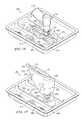
- FIG. 1Cis a schematic drawing showing an isometric view of one example of a medical procedure tray including a biopsy needle set and other components satisfactory for use with a powered driver in a sterile environment in accordance with teachings of the present disclosure;
- FIG. 1Dis a drawing in section taken along lines 1 D- 1 D of FIG. 1C ;
- FIG. 1Eis a schematic drawing showing an isometric view of the medical procedure tray of FIG. 1D with a non-sterile medical device disposed in a containment bag in accordance with teachings of the present disclosure;
- FIG. 1Fis a schematic drawing showing still another isometric view of the medical procedure tray of FIG. 1D with the non-sterile medical device disposed in the containment bag in accordance with teachings of the present disclosure;
- FIG. 1Gis a schematic drawing showing a further isometric view of the medical procedure tray of FIG. 1C ;
- FIG. 1His a schematic drawing showing an isometric view of the medical procedure tray of FIG. 1G after unfolding a first drape and a second drape;
- FIG. 1Iis a schematic drawing showing an isometric view of the medical procedure tray of FIG. 1G after a powered driver has been engaged with a coupler assembly in accordance with teachings of the present disclosure
- FIG. 1Jis a schematic showing an isometric view of the medical procedure tray of FIG. 1G after lifting the second drape to enclose the powered driver (one example of a non-sterile medical device) in the containment bag;
- the powered driverone example of a non-sterile medical device
- FIG. 2is a schematic drawing showing one example of a powered driver operable for use with intraosseous (IO) devices incorporating teachings of the present disclosure
- FIG. 3Ais a schematic drawing showing an isometric view of the aspiration needle of FIG. 1A ;
- FIG. 3Bis a schematic drawing showing an exploded view of the aspiration needle set of FIG. 3A ;
- FIG. 3Cis a schematic drawing showing an exploded, isometric view of one example of a biopsy needle incorporating teachings of the present disclosure
- FIG. 3Dis a schematic drawing showing an isometric view of another example of an intraosseous needle set incorporating teachings of the present disclosure
- FIG. 3Eis a schematic drawing showing an isometric view with portions broken away of the tips of the intraosseous needle set of FIG. 3A ;
- FIG. 3Fis a schematic drawing showing an isometric view of one embodiment of the tip of an intraosseous device or cannula incorporating teachings of the present disclosure
- FIG. 3Gis a schematic drawing showing an isometric view of another embodiment of the tip of a biopsy needle incorporating teachings of the present disclosure
- FIG. 3His a schematic drawing showing an isometric view of still another embodiment of the tip of an intraosseous device or catheter incorporating teachings of the present disclosure
- FIG. 3Iis a schematic drawing showing an isometric view with portions broken away of a intraosseous needle set incorporating teachings of the present disclosure
- FIG. 3Jis a schematic drawing showing an isometric view with portions broken away of another example of a biopsy needle set incorporating teachings of the present disclosure
- FIG. 4Ais a schematic drawing partially in section and partially in elevation with portions broken away showing an exploded isometric view of a mandrel operable to install a thread insert within portions of a biopsy needle in accordance with teachings of the present disclosure
- FIG. 4Bis a schematic drawing showing one example of a thread insert which may be disposed within the longitudinal bore of a biopsy needle in accordance with teachings of the present disclosure
- FIG. 4Cis a schematic drawing in section with portions broken away showing one example of a biopsy needle with a single helical thread disposed within one end of the biopsy needle incorporating teachings of the present disclosure
- FIG. 4Dis a schematic drawing in section with portions broken away showing another example of a biopsy needle with a single helical thread disposed within one end of the biopsy needle in accordance with teachings of the present disclosure
- FIG. 4Eis a schematic drawing in section and in elevation with portions broken away showing a biopsy needle set including a trocar and a single helical thread disposed proximate one end of a generally hollow cannula in accordance with teachings of the present disclosure;
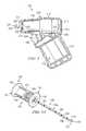
- FIG. 5Ais a schematic drawing showing an exploded, isometric view of a powered driver, coupler assembly and an intraosseous device incorporating teachings of the present disclosure
- FIG. 5Bis a schematic drawing showing another exploded, isometric view of the coupler assembly and intraosseous device of FIG. 5A ;
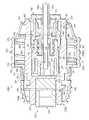
- FIG. 5Cis a schematic drawing in section with portions broken away showing another exploded view of the powered driver, coupler assembly and intraosseous device of FIG. 5A ;
- FIG. 5Dis schematic drawing showing an end view of the coupler assembly taken along lines 5 D- 5 D of FIG. 5C prior to insert one end of a device shaft therein;
- FIG. 5Eis a schematic drawing in section with portions broken away showing the powered driver, coupler assembly and intraosseous device of FIG. 5A ;
- FIG. 5Fis a schematic drawing in section with portions broken away showing the coupler assembly of FIG. 5D in a second position allowing release of a powered driver from a receptacle disposed in the first end of the coupler assembly;
- FIG. 5Gis a schematic drawing in section showing various features of a coupler assembly and latch mechanism incorporating teachings of the present disclosure taken along lines 5 G- 5 G of FIG. 5E ;
- FIG. 5His a schematic drawing in section showing various features of a coupler assembly and latch mechanism incorporating teachings of the present disclosure taken along lines 5 H- 5 H of FIG. 5F ;
- FIG. 5Iis a schematic drawing in section with portions broken away showing another example of a coupler assembly incorporating teachings of the present disclosure
- FIG. 6Ais a schematic drawing showing an alternative embodiment of a coupler assembly operable to releasably engage an intraosseous device with one end of a drive shaft extending from a powered driver in accordance with teachings of the present disclosure
- FIG. 6Bis a schematic drawing in section with portions broken away showing portions of the powered driver, coupler assembly and intraosseous device of FIG. 6A ;
- FIG. 7Ais a schematic drawing showing an isometric view with portions broken away of a powered driver, containment bag or sterile sleeve and coupler assembly incorporating teachings of the present disclosure
- FIG. 7Bis a schematic drawing showing another view of the powered driver disposed in the containment bag of FIG. 7A in accordance with teachings of the present disclosure
- FIG. 8is a schematic drawing showing an exploded isometric view of an intraosseous device and a coupler assembly incorporating teachings of the present disclosure which may be satisfactorily used with a powered driver in accordance with teachings of the present disclosure or a manual driver;
- FIG. 9Ais a schematic drawing showing an exploded, isometric view of a biopsy specimen ejector and associated funnel incorporating teachings of the present disclosure
- FIG. 9Bis a schematic drawing showing an isometric view of another example of a biopsy specimen ejector and associated funnel incorporating teachings of the present disclosure.
- FIG. 9Cis a schematic drawing in section of the funnel of FIG. 9B ;
- FIG. 10is a schematic drawing in section and in elevation with portions broken away showing an aspiration needle disposed at a target site and communicating with a bone marrow aspiration system in accordance with teachings of the present disclosure.
- FIGS. 1A-10Preferred embodiments of the disclosure and various advantages may be understood by reference to FIGS. 1A-10 , wherein like numbers refer to same and like parts.
- ment bagmay include any sterile sleeve, sterile envelope, sterile glove, sterile enclosure or any other device incorporating teachings of the present disclosure and operable to allow engaging a non-sterile device with a sterile device and conducting a medical procedure requiring a sterile field or sterile environment.
- a non-sterile powered drivermay be placed in a containment bag incorporating teachings of the present disclosure and engaged with a sterile intraosseous device for use during various medical procedures requiring a sterile field or sterile environment.
- Such containment bagsmay be attached to a coupler assembly or any other device incorporating teachings of the present disclosure to prevent the non-sterile powered driver from contaminating the sterile intraosseous (IO) device during and after engagement of the non-sterile powered driver with the IO device.
- IOsterile intraosseous
- driveras used in this application may include any type of powered driver satisfactory for inserting an intraosseous (IO) device into a selected portion of a patient's vascular system. Such powered drivers often rotate a drive shaft extending therefrom. However, various teachings of the present disclosure may be used with powered drivers that reciprocate an associated drive shaft (not expressly shown).
- IOintraosseous
- Various techniquesmay be satisfactorily used to releasably engage or attach an IO device with a powered driver in accordance with teachings of the present disclosure.
- a wide variety of coupler assemblies, port assemblies, connectors, receptacles, fittings, hubs, hub assemblies, latching mechanisms and/or other types of connecting devices incorporating teachings of the present disclosuremay be satisfactorily used to releasably engage an IO device with a powered driver.
- coupler assembliesincorporating teachings of the present disclosure may be satisfactorily used to releasably engage one end of a shaft extending from a driver with one end of an intraosseous device.
- the powered drivermay include a drive shaft having one end with a generally hexagonal cross section operable to be releasably engaged with a latch mechanism disposed in one end of a coupler assembly.
- a coupler assembly incorporating teachings of the present disclosuremay be referred to as a “hands free” coupler, a quick disconnect or quick release coupler and/or port assembly.
- Respective latch mechanismsmay be disposed proximate a first end and a second end of a coupler assembly in accordance with teachings of the present disclosure. Pushing one end of a drive shaft extending from a powered driver into the second end of the coupler assembly may result in an annular recess disposed in the one end of the drive shaft “snapping” into releasable engagement with the respective latch mechanism. Pushing one end of an intraosseous device into the first end of the coupler assembly may result in an annular recess in the one end of the intraosseous device “snapping” into releasable engagement with the respective latch mechanism.
- a coupler assembly or port assemblymay be engaged with a containment bag or sterile sleeve in accordance with teachings of the present disclosure.
- Coupler assemblies and/or hub assemblies incorporating teachings of the present disclosureallow easy separation of an associated powered driver from an IO device such that the IO device may remain in place in a patient to allow bone marrow aspiration or removal of bone and/or bone marrow biopsy specimens.
- Such coupler assemblies and/or port assembliesmay also allow an associated powered driver to “spin” or rotate an attached IO device while withdrawing an IO device from an insertion site or changing the depth of penetration of an IO device in a target area. Rotating the IO device during withdrawal or changing depth (power out) may substantially improve patient comfort and reduce potential trauma to bone and soft body tissue proximate an insertion site.
- a powered drivermay be used to insert an IO device incorporating teachings of the present disclosure into a selected target area or target site in ten seconds or less.
- various teachings of the present disclosureare not limited to use with powered drivers.
- Manual drivers and spring powered driversmay also be used with IO devices incorporating teachings of the present disclosure.
- fluidmay be used in this application to include liquids such as, but not limited to, blood, water, saline solutions, IV solutions, plasma or any mixture of liquids, particulate matter, dissolved medication and/or drugs associated with biopsy or aspiration of bone marrow or communication of fluids with bone marrow or other target sites.
- fluidmay also be used in this patent application to include any body fluids and/or liquids containing particulate matter such as bone marrow and/or cells which may be withdrawn from a target area.
- Bone and/or bone marrow biopsymay be generally described as removing a relatively small piece or specimen of bone and/or bone marrow from a selected target area for biopsy purposes.
- Bone marrow aspiration(sometimes referred to as “bone marrow sampling”) may be generally described as removing larger quantities of bone marrow from a selected target area. Relatively large quantities of bone marrow may be used for diagnostic, transplantation and/or research purposes. For example some stem cell research techniques may require relatively large quantities of bone marrow.
- Insertion sitemay be used in this application to describe a location on a bone at which an intraosseous device may be inserted or drilled into the bone and associated bone marrow. Insertion sites, penetration sites and installation sites are generally covered by skin and soft tissue.
- intraosseous (IO) devicemay be used in this application to include, but is not limited to, any hollow needle, hollow drill bit, penetrator assembly, bone penetrator, catheter, cannula, trocar, stylet, inner penetrator, outer penetrator, IO needle, biopsy needle, aspiration needle, IO needle set, biopsy needle set or aspiration needle set operable to provide access to an intraosseous space or interior portions of a bone.
- IO devicesmay be formed, at least in part, from metal alloys such as 304 stainless steel and other biocompatible materials associated with needles and similar medical devices.
- IO devicesmay be formed in accordance with teachings of the present disclosure.
- Examples of such IO devicesmay include, but are not limited to, biopsy needles, biopsy needle sets, aspiration needles and aspiration needle sets.
- IO devicesmay or may not include a trocar or stylet.
- a trocar or styletmay be inserted into a generally hollow, longitudinal bore or lumen in an associated catheter or cannula.
- the first end of the second hubmay be releasably engaged with second end of the first hub to releasably dispose the stylet or trocar within the longitudinal bore of the cannula or catheter.
- the present disclosureis not limited to aspiration needle sets 100 or biopsy needle sets 100 a as discussed in this application.
- target areamay be used in this application to describe selected portions of a bone cavity or locations in a bone cavity from which associated bone marrow may be harvested in accordance with teachings of the present disclosure.
- Many currently available techniques for harvesting bone and/or bone marrowmay require more than one penetration into a bone and associated bone marrow to retrieve an adequate sample of bone and/or bone marrow.
- Multiple penetration sitesmay be required in the same bone if a biopsy specimen is not satisfactorily retrieved at the first penetration site.
- Medical personnelmay need to insert an IO needle into several different penetration sites on the same bone to obtain adequate quantities of bone marrow for transplant or stem cell research. For example obtaining sufficient quantities of bone marrow from a patient's pelvis may require six or more insertion sites.
- Multiple insertionsmay be extremely painful for a patient and may deter some people from donating bone marrow. Multiple insertions may also cause fatigue in medical personnel performing such procedures with manual IO devices.
- Bone marrow transplant procedures and various research procedures such as stem cell researchoften require relatively large quantities of bone and/or bone marrow.
- Hip bonesgenerally have a large bone cavity and are therefore frequently used as a target area for harvesting bone marrow for transplant procedures, stem cell research procedures or any other procedure requiring relatively large quantities of bone marrow.
- an IO needle or other IO devicemay be formed with a first end operable to penetrate bone and/or associated bone marrow.
- a connector or hubmay be attached to a second end of the IO needle or other IO device.
- Such connectors or hubsmay be operable to releasably engage the IO needle or IO device with a powered driver, a manual driver and/or a coupler assembly.
- IO needle sets and other IO devices incorporating teachings of the present disclosuremay include a first IO device such as a cannula, catheter or outer penetrator and a second IO device such as a stylet, trocar or inner penetrator.
- a first IO devicesuch as a cannula, catheter or outer penetrator
- a second IO devicesuch as a stylet, trocar or inner penetrator.
- Various types of cutting surfacesmay be formed proximate a first end of the first IO device and a first end of the second IO device.
- the cutting surface of the first IO device and the cutting surface of the second IO devicemay cooperate with each other to penetrate bone and/or associated bone marrow.
- a first connector or first hubmay be used to releasably engage the first IO needle or IO device with the second IO needle or IO device.
- an IO needle setmay include a first connector or a first hub with a generally hollow cannula, catheter or outer penetrator attached thereto and extending from a first end of the first hub.
- a second end of the first hubmay be operable to be releasably engaged with a first end of a second connector or a second hub.
- a stylet, trocar or inner penetratormay also be attached to and extend from the first end of the second hub.
- the second end of the first hubmay include an opening sized to allow inserting the stylet, trocar or inner penetrator through the opening and a lumen in the cannula, catheter or outer penetrator.
- a second end of the second hubmay be operable to be releasably engaged with a first end of a coupler assembly incorporating teachings of the present disclosure.
- One end of a shaft extending from a powered driver or a manual drivermay be releasably engaged with a second end of the coupler assembly.
- powered driver 200coupler assemblies 250 , 250 a , 250 b and 250 c , hub assemblies 130 , 130 a , 130 b and 130 c , IO needle sets 100 , 100 a and 100 b biopsy needle 100 c and/or containment bag 170 .
- the present disclosureis not limited to such powered drivers, coupler assemblies, hub assemblies, IO needle sets, biopsy needles and/or containment bags.
- a wide variety of intraosseous devices, hub assemblies, coupler assemblies and/or containment bagsmay be formed in accordance with teachings of the present disclosure with various dimensions and/or configurations.
- FIGS. 1A-1Jshow some examples of medical procedure trays and/or kits which may contain one or more intraosseous devices and/or other components incorporating teachings of the present disclosure.
- medical procedure tray 20 a as shown in FIG. 1Amay include intraosseous needle set or aspiration needle set 100 incorporating various teachings of the present disclosure.
- Medical procedure tray 20 b as shown in FIG. 1Bmay include intraosseous needle set or biopsy needle set 100 b , ejector 90 , funnel 80 and/or containment bag or sterile sleeve 170 .
- Medical procedure tray 20 c as shown in FIGS. 1C-1Imay also include various IO devices and other components incorporating teachings of the present disclosure including, but not limited to, biopsy needle set 100 b , coupler assembly 250 , containment bag 170 , ejector 90 and/or funnel 80 a.
- Medical procedure trays and/or kits formed in accordance with teachings of the present disclosuremay provide a support or base for various components such as a coupler assembly, funnel and/or sharps protector to allow an operator or user to perform various functions without requiring that the operator or user hold or manipulate the respective component.
- medical procedure tray 20 c as shown in FIG. 1may position and support coupler assembly 250 such that one end of a powered driver may be inserted (pushed) into releasable engagement with second end 252 of coupler assembly 250 . The powered driver may then be used to withdraw coupler assembly 250 from medical procedure tray 20 c without requiring an operator or user to directly hold or manipulate coupler assembly 250 .
- Funnel 80 amay be positioned and supported within medical procedure tray 20 c such that one end of an intraosseous device may be inserted (pushed) into funnel 80 a . Funnel 80 a may be withdrawn from medical procedure tray 20 c without requiring that an operator or user directly hold or manipulate funnel 80 a . Each sharps protector 64 a may also be positioned and supported within medical procedure tray 20 c to allow inserting (pushing) one end of an intraosseous device or any other medical device requiring sharps protection into sharps protector 64 a without requiring that an operator or user to directly hold or manipulate the associated sharps protector 64 a .
- Medical procedure trays, coupler assemblies and other components formed in accordance with teachings of the present disclosuremay substantially reduce the number of opportunities for an accidental “needle stick” and/or dropping, contaminating or other problems associated with handling and manipulating various components disposed within an associated medical procedure tray.
- Medical procedure trays and kits formed in accordance with teachings of the present disclosuremay have a wide variety of configurations and/or dimensions.
- a kit holding intraosseous devices in accordance with teachings of the present disclosuremay have an overall length of approximately four and one-half inches, a width of approximately three inches and a depth of approximately two inches.
- Various heat sealing techniquesmay be satisfactorily used to place a removable cover (not expressly shown) over a medical procedure tray or kit incorporating teachings of the present disclosure.
- Medical procedure trays 20 a , 20 b and/or 20 cmay also contain a wide variety of other components including, but not limited to, one or more sharps protectors 64 as shown in FIGS. 1A and 1B or sharps protectors 64 a as shown in FIGS. 1C , 1 E and 1 F.
- Sharps protectors 64 and 64 amay include hard foam or claylike material 66 disposed therein.
- Intraosseous devicessuch as aspiration needle sets and biopsy needle sets typically have respective sharp tips and/or cutting surface operable to penetrate skin, soft tissue and bone. The sharp tips and/or cutting surface of such intraosseous devices may be inserted into hard foam or claylike material 66 after completion of a medical procedure using the respective intraosseous device.
- medical procedure tray 20 amay be referred to as a “bone marrow aspiration tray,” “aspiration procedure tray” or “bone marrow aspiration kit”.
- medical procedure trays 20 b and 20 cmay sometimes be referred to as “bone and/or bone marrow biopsy procedure trays” or “biopsy procedure trays” or “bone marrow biopsy kits.”
- Medical procedure trays 20 a , 20 b and/or 20 cmay be formed from various polymeric materials compatible with sterile packaging and storage of various components disposed within each medical procedure tray.
- ethylene oxide sterilization techniquesmay be used during assembly and packaging of medical procedure trays 20 a , 20 b and 20 c .
- other sterilization proceduresmay be used as appropriate.
- Respective coversmay be placed over each medical procedure tray 20 a , 20 b and 20 c as part of an associated sterilization and packaging process. Such covers may be removed prior to use of various components disposed within each medical procedure tray.
- Medical procedure tray or aspiration tray 20 amay include elongated slot 22 with appropriate dimensions for an associated intraosseous device such as, but not limited to, aspiration needle set 100 .
- the dimensions and configuration of slot 22may be selected to accommodate the combined length of hub assembly 130 and cannula 110 a extending therefrom.
- One end of slot 22may be sized to accommodate the dimensions and configuration of hub assembly 130 .
- Enlarged openings or finger slots 24may also be provided to accommodate inserting and removing aspiration needle set 100 from slot 22 .
- Aspiration needle set 100will be discussed later with respect to FIG. 3A .
- Sharps protector 64may be disposed within holder 26 of medical procedure tray 20 a .
- a pair of finger slots 28may also be formed in tray 20 a to accommodate inserting and removing sharps protector 64 from holder 26 a .
- Holder 26 bmay also be formed in tray 20 a along with associated finger slots 28 .
- An additional sharps protector or other componentsmay be disposed within holder 26 b .
- the dimensions/configurations of slot 22 and holders 26 a and 26 bmay be varied as desired for respective components which will be disposed therein.
- Medical procedure tray or biopsy tray 20 bmay include elongated slots 30 and 32 .
- the dimensions and configuration of elongated slot 30may be selected to accommodate placing ejector 90 therein.
- the dimensions and configuration of elongated slot 32may be selected to accommodate placing intraosseous device or biopsy needle set 100 b therein.
- One end of elongated slot 30may have configuration and dimensions selected to accommodate the configuration and dimensions of handle 96 disposed on second end 92 of injector rod 94 .
- a pair of finger slots 34may be formed as part of elongated slot 30 to allow installing and removing ejector 90 .
- One end of elongated slot 32may be operable to accommodate the configuration and dimensions associated with hub assembly 130 a of biopsy needle set 100 b .
- a pair of finger slots 36may also be provided as part of elongated slot 32 to accommodate inserting and removing biopsy needle set 100 b from elongated slot 32 .
- Tray 20 bmay also include holder 38 disposed adjacent to elongated slot 30 .
- Holder 38may have a configuration and dimensions compatible with releasably placing funnel 80 therein.
- Tray 20 bmay also include compartment or holder 40 with dimensions compatible with placing containment bag 170 with coupler assembly 250 attached thereto.
- One or more specimen or sample containers or cupsmay be provided in biopsy tray 20 b .
- Biopsy specimen or sample containersmay include a cavity sized to receive a biopsy specimen from biopsy needle set 100 b .
- Funnel holders 38may be formed in biopsy procedure tray 20 b adjacent to ejector 90 to ensure that funnel 80 is readily available to assist with removing a biopsy specimen from biopsy needle set 100 b.
- Biopsy procedure tray 20 cas shown in FIGS. 1C-1I represents another example of a medical procedure tray formed in accordance with teachings of the present disclosure.
- Biopsy procedure tray 20 cmay include intraosseous device or biopsy needle set 100 b releasably disposed in elongated slot 42 and ejector 90 disposed in elongated slot 44 . Respective ends of elongated slots 42 and 44 may be disposed adjacent to each other so that finger slots 46 a , 46 b and 46 c may be more easily manufactured.
- Biopsy procedure tray 20 calso includes a pair of sharps protectors 64 a disposed in respective holders 48 . Each holder 48 includes a pair of finger slots 50 .
- Funnel 80 amay be slidably disposed in holder 56 in medical procedure tray 20 c in a generally vertical position. See FIG. 1D .
- first end 81 a of funnel 80 amay be oriented in a position to allow inserting one end of biopsy needle set 100 b or outer cannula 110 b therein.
- Longitudinal passageway 84 proximate first end 81 amay include a sticking tapered portion operable to maintain contact with one end of biopsy needle set 100 b or outer cannula 110 b .
- Biopsy needle set 100 b or cannula 110 bmay then be manipulated to pull funnel 80 a from holder 56 .
- Funnel 80 amay serve as a sharps protector for the one end of an intraosseous device inserted therein.
- One of the benefits of the present disclosuremay include being able to releasably engage one end of a powered driver with one end of a coupler assembly, releasably engage one end of a biopsy needle with an opposite end of the coupler assembly, insert another end of the biopsy needle into a selected target area, “power out” the biopsy needle with a high degree of confidence that a biopsy specimen will be disposed therein and insert the other end of the biopsy needle into a funnel to provide both sharps protection and removal of the biopsy specimen. Any direct contact between an operator and the biopsy needle may be limited to pushing the one end of the biopsy needle into a respective end of the coupler assembly.
- a pair of holders or clampsmay also be formed in medical procedure tray 20 c adjacent to holder for coupler assembly 250 .
- Such clampsmay be designed to accommodate first end 181 and second end 182 of flexible stay 180 disposed on second opening 172 of containment bag 170 .
- Coupler assembly 250may also be installed in holder 58 of biopsy procedure tray 20 c with first end 251 down and second end 252 looking up.
- FIGS. 1E and 1Fshow one procedure for placing a powered driver within a containment bag incorporating teachings of the present disclosure.
- Containment bag 170may be formed from generally flexible, fluid impervious material which may also be sterilized using conventional sterilization techniques. Containment bag 170 may be used to prevent a non-sterile powered driver from contaminating a sterile intraosseous device and/or an injection site, particularly during a bone marrow biopsy procedure or a bone marrow aspiration procedure. Containment bag 170 may be operable to form a fluid barrier with adjacent portions of housing assembly 270 .
- coupler assembly 250may allow powered driver to rotate an intraosseous device releasably engaged with first end 251 of coupler assembly 250 without damage to containment bag 170 .
- First opening 171may be formed along one edge of containment bag or sleeve 170 .
- Second opening 172may be formed along an opposite edge of containment bag 170 .
- the configuration and dimensions of second opening 172may be selected to accommodate inserting and removing a powered driver or other non-sterile medical device therefrom.
- Coupler assembly 250may be securely engaged with and extend from first opening 171 .
- the attachment between adjacent portions of first opening 171 and coupler assembly 250may be selected to allow rotation of an intraosseous device by an associated powered drive.
- Housing assembly 270 and/or housing segments 280 and 290 of coupler assembly 250may remain relatively stationary during rotation of elongated core 260 . See FIG. 5F .
- portions of housing assembly 270such as flange 254 extending from second end 252 of coupler assembly 250 may be attached to first opening 171 and remain relatively stationary while powered driver 200 rotates elongated core 260 and aspiration needle set 100 extending therefrom.
- powered driver 200may be directly placed into a containment bag and engaged with coupler assembly 250 .
- a non-sterile powered drivermay be inserted into containment bag 170 in connection with removing coupler assembly 250 from a medical procedure tray.
- a protective cover(not expressly shown) may be removed from medical procedure tray 20 c .
- End 224 extending from drive shaft 222 of powered driver 200may then be inserted through second opening 172 of containment bag 170 and releasably engaged with second end 252 of coupler assembly 250 .
- First end 181 and second end 182 of flexible stay 180may then be removed from respective clamps or holders in medical procedure tray 20 c to allow manually lifting second opening 172 upwardly relative to powered driver 200 . See FIG. 1E .
- Containment bag 170may continue to be raised to a fully extended position with powered driver 200 disposed therein. See FIG. 1F .
- Flap 174may then be placed over second opening 172 .
- Containment bag 170 with powered driver 200 disposed therein and coupler assembly 250may then be removed from holder 58 of medical procedure tray 20 c.
- FIGS. 1G-1Jshow another procedure incorporating teachings of the present disclosure to place a non-sterile powered driver into a containment bag with a coupler assembly or port assembly extending therefrom and enclosing the non-sterile powered driver within the containment bag to allow engaging the coupler assembly with a sterile intraosseous device.
- the same proceduremay be used to engage other non-sterile medical devices with sterile medical devices.
- medical procedure tray 20 cmay be placed in second tray 20 d with first drape 51 disposed therebetween. See FIGS. 1G and 1J .
- Second drape 52 with opening or fenestration 54may then be placed over medical procedure tray 20 c with opening or fenestration 54 generally aligned with second opening 172 of containment bag 170 and second end 252 of coupler assembly 250 .
- Second drape 52may also cover portions of first drape 51 extending outwardly from between medical procedure tray 20 c and the second medical procedure tray (not expressly shown).
- portions of second drape 52 adjacent to fenestration 54may be releasably engaged with portions of containment bag 170 adjacent to second opening 172 . See FIG. 1J .
- Various commercially available low strength adhesive materialsmay be satisfactorily used to provide releasable engagement between second drape 52 proximate fenestration 54 and second opening 172 of containment bag 170 .
- First drape 51 and second drape 52may then be folded with each other and covering the contents of medical procedure tray 20 c such as shown in FIG. 1G .
- a portion of second drape 52may be seen in FIG. 1G between respective portions of first drape 51 .
- a protective covermay then be placed over both medical procedure trays and any exposed portions of drapes 51 and 52 .
- the combined medical procedure tray(not expressly shown) may then be sterilized.
- One benefit of such sterilizationinclude, but is not limited to, providing a sterilized containment bag which may be used to engage a non-sterile medical device with a sterile medical device in accordance with teachings of the present disclosure.
- First drape 51 and second drape 52may then be unfolded as shown in FIG. 1H which will expose second opening 172 of containment bag 170 and second end 252 of coupler assembly 250 through fenestration 54 in second drape 52 .
- a non-sterile person(not expressly shown) may next insert non-sterile powered driver 200 through opening or fenestration 54 and releasably engage end 224 of drive shaft 222 extending from non-sterile powered driver 200 with second end 252 of coupler assembly 250 .
- the non-sterile personmay then lift second drape 52 to a position such as shown in FIG. 1J with powered driver 200 disposed within containment bag 170 .
- the non-sterile personmay continue to lift second drape 52 to release engagement between portions of second drape 52 adjacent to fenestration 54 and portions of containment bag 170 adjacent to second opening 172 .
- Typical procedures associated with using a medical procedure tray or kit incorporating teachings of the present disclosuremay include the following steps.
- Medical procedure tray 20 dat a desired location for performing an associated medical procedure.
- medical procedure tray 20 dmay be placed on a table or cart adjacent to a surgical table on which a bone marrow aspiration procedure or a bone marrow biopsy procedure may be performed.
- An associated covermay be removed from medical procedure tray 20 d by a sterile person to expose folded drapes 51 and 52 . Drapes 51 and 52 may then be unfolded by the sterile person such as shown in FIG. 1H .
- a non-sterile personmay then pick up non-sterile powered driver 200 and insert powered driver 200 through fenestration 54 in second drape 52 such as shown in FIG. 1H .
- End 224 of drive shaft 222 of powered driver 200may “snap” into place within second end 252 of coupler assembly 250 .
- the non-sterile personmay then lift second drape 52 such as shown in FIG. 1J which will result in lifting containment bag 170 up and over powered driver 200 .
- the non-sterile personmay then remove second drape 52 .
- a sterile personmay next close flap 174 over second end 172 of containment bag 170 .
- the sterile personmay then grasp handle 214 of powered driver 200 through containment bag 170 and lift powered driver 200 with coupler assembly 250 attached thereto from holder 58 disposed in kit 20 c .
- the sterile personmay then remove an intraosseous device such as biopsy needle set 100 b from medical procedure kit 20 c and insert second end 102 of biopsy needle set 100 b into first end 251 of coupler assembly 250 .
- a “snap”may be felt when second end 102 of biopsy needle set 100 b (or any other intraosseous device incorporating teachings of the present disclosure) is releasably latched within first end 251 of coupler assembly 250 .
- a needle safety cap(not expressly shown) may be removed from first end 101 of biopsy needle 100 b after releasably engaging second end 102 with first end 251 of coupler assembly 250 .
- Powered driver 200 disposed within containment bag 170 along with coupler assembly 250 and biopsy needle set 100 b extending there frommay be held in one hand while a sterile person identifies the insertion site with the other hand.
- Powered driver 200may be positioned over the insertion site to introduce first end 101 of biopsy needle set 100 b through the skin in the direction and towards the bone.
- the operatormay squeeze button or trigger 246 and apply relatively steady gentle pressure to handle 214 of powered driver 200 .
- the operatormay release trigger 246 to stop further insertion of first end 101 of biopsy needle set 100 b.
- First housing segment 280may then be activated to release second end 102 of biopsy needle set 100 b from engagement with coupler assembly 250 .
- Second hub 150 amay then be rotated counterclockwise to disengage second hub 150 a and associated stylet 120 from first hub 140 a . See FIG. 3B .
- Stylet 120may then be pulled out and removed from biopsy needle or cannula 110 b .
- First end 121 of stylet 120may then be inserted into sharps protector 64 a .
- second hub 150 amay be reengaged with first hub 140 a .
- First end 251 of coupler assembly 250may then be reengaged with second end 102 of biopsy needle set 100 b to rotate or spin biopsy needle set 100 b while withdrawing from the insertion site.
- second end 102 of biopsy needle set 100 bmay be disengaged from coupler assembly 250 .
- First end 101 of biopsy needle set 100 bmay then be inserted into sharps container 64 a.
- a sterile personmay close flap 174 to seal non-sterile powered driver therein.
- the sterile personmay then remove containment bag 170 , powered driver 200 and coupler assembly 250 from holder 58 .
- the sterile personmay then releasably engage first end 251 of coupler assembly 250 with one end of a sterile intraosseous device disposed within medical procedure tray 20 c in accordance with teachings of the present disclosure.
- the sharp end or sharp tip of the intraosseous devicemay be inserted into material 66 in sharp protector 64 a for further disposal in accordance with the appropriate procedures.
- first drape 51 and/or second drape 52may be formed from a wide variety of materials and may have a wide variety of configurations and/or dimensions.
- Powered driver 200 as shown in FIGS. 1E , 1 F, 1 I, 2 , and 5 A and powered driver 200 a as shown in FIGS. 7A and 7Bmay be satisfactorily used to insert an intraosseous device incorporating teachings of the present disclosure into a bone and associated bone marrow.
- Powered drivers 200 and 200 amay be substantially similar except for respective ends 224 and 224 a of drive shaft 222 extending from first end 211 of housing 210 . See for example FIGS. 2 and 7A . Therefore, only powered driver 200 will be described in more detail.
- Powered driver 200may include housing 210 having a general configuration similar to a small pistol defined in part by handle 214 .
- Various components associated with powered driver 200may be disposed within housing 210 including handle 214 .
- a power sourcesuch as battery pack 216 may be disposed within handle 214 .
- Battery pack 216may have various configurations and dimensions.
- Housing 210 including handle 214may be formed from relatively strong, heavy duty polymeric materials such as polycarbonate or other satisfactory materials.
- housing 210may be formed in two halves (not expressly shown) which may be joined together with a fluid tight seal to protect various components of powered driver 200 disposed therein.
- Motor 218 and gear assembly 220may be disposed within portions of housing 210 adjacent to handle 214 . Motor 218 and gear assembly 220 may be generally aligned with each other. Motor 218 may be rotatably engaged with one end of gear assembly 220 . Drive shaft 222 may be rotatably engaged with and extend from another end of gear assembly 220 opposite from motor 218 . For some applications both motor 218 and gear assembly 220 may have generally cylindrical configurations.
- Motors and gear assemblies satisfactory for use with powered driver 200may be obtained from various vendors. Such motor and gear assemblies may be ordered as “sets” with one end of each motor securely attached to an adjacent end of an associated gear assembly. A drive shaft having various dimensions and/or configurations may extend from the gear assembly opposite from the motor. Such gear assemblies may sometimes be referred to as “reduction gears” or “planetary gears”. The dimensions and/or configuration of housing 210 may be modified to accommodate an associated motor and gear assembly.
- Distal end or first end 211 of housing 210may include an opening (not expressly shown) with portions of drive shaft 222 extending therefrom.
- end 224 or the portion of drive shaft 222 extending from first end 211 of housing 210may have a generally hexagonal cross section with surfaces 226 disposed thereon.
- Receptacle 263 disposed in second end 252 of coupler assembly 250may have a matching generally hexagonal cross section. See FIG. 5E .
- Surfaces 226may extend generally parallel with each other and parallel with respect to a longitudinal axis or rotational axis (not expressly shown) associated with drive shaft 222 .
- One or more tapered surfaces 228may also be formed on end 224 to assist with releasably engaging powered driver 200 with coupler assembly 250 . See FIGS. 5E and 5G .
- the end of a drive shaft extending from a powered drivermay have a wide variety of configurations. See for example FIGS. 6A and 6B .
- a drive shaft having desired dimensions and configurationmay extend from the gear assembly opposite from the motor.
- the drive shaftmay be provided as part of each motor and gear assembly set.
- the dimensions and/or configuration of an associated housingmay be modified in accordance with teachings of the present disclosure to accommodate various types of motors, gear assemblies and/or drive shafts.
- powered drivers used with aspiration needles and/or biopsy needlesmay include gear assemblies with larger dimensions required to accommodate larger speed reduction ratios, for example between 60:1 and 80:1, resulting in slower drive shaft RPM's.
- Powered drivers used to provide intraosseous access during emergency medical proceduresmay operate at a higher speed and may include gear assemblies having a smaller speed reduction ratio, for example between 10:1 and 30:1, resulting in higher drive shaft RPM's.
- the difference in size for gear assembliesmay result in increasing the inside diameter of an associated housing by approximately two to three millimeters to accommodate larger gear assemblies associated with powered drivers used to insert biopsy needles and/or aspiration needles.
- Coupler assemblies having corresponding openings or receptaclesmay be releasably engaged with end 224 extending from first end 211 of powered driver 200 or end 224 a extending from first end 211 of powered driver 200 a .
- end 224 extending from first end 211 of housing 210may be releasably engaged with receptacle 264 disposed proximate second end 252 of coupler assembly 250 as shown in FIGS. 1E , 1 F, 5 C and 5 D.
- thrust bearing 241may be disposed between first end or distal end 211 of housing 210 and adjacent portions of gear assembly 220 .
- Thrust bearing 242may be disposed between second end or proximal end 212 of housing 210 and adjacent portions of motor 218 .
- Thrust bearings 241 and 242may limit longitudinal movement of motor 218 , gear assembly 220 and drive shaft 222 within associated portions of housing 210 .
- Trigger assembly 244may also be disposed within housing 210 proximate handle 214 .
- Trigger assembly 244may include trigger or contact switch 246 .
- Motor 218may be energized and deenergized by alternately depressing and releasing trigger 246 .
- Electrical circuit board 247may also be disposed within housing 210 . Electrical circuit board 247 may be electrically coupled with trigger assembly 244 , motor 218 , power supply 216 and indicator light 248 .
- indicator light 248may be a light emitting diode (LED) or a small more conventional light bulb.
- indicator light 248may be activated when ninety percent (90%) of electrical storage capacity of battery pack 216 has been used.
- an intraosseous device formed in accordance with teachings of the present disclosuremay vary depending upon respective intended applications for each intraosseous device.
- the length of a biopsy needle formed in accordance with teachings of the present disclosuremay vary from approximately five (5) millimeters to thirty (30) millimeters.
- biopsy needles having other lengthsmay also be formed in accordance with teachings of the present disclosure.
- Aspiration needles formed in accordance with teachings of the present disclosuremay have lengths of approximately twenty five (25) millimeters, sixty (60) millimeters and ninety (90) millimeters.
- an aspiration needle having a length of ninety (90) millimeters or moremay also include one or more side ports. See for example FIG.
- Intraosseous (IO) devices formed in accordance with teachings of the present disclosuremay have outside diameters and longitudinal bores or lumens corresponding generally with eighteen (18) gauge to ten (10) gauge needles. The configuration and dimensions of each IO device may depend upon the size of an associated bone and desired depth of penetration of associated bone marrow.
- Bone marrow aspiration systemsmay be capable of inserting an aspiration needle to a desired depth in cancellous bone in ten (10) to fifteen (15) seconds. This same capability may be used to obtain bone and/or bone marrow specimens depending upon the optimum speed for inserting a biopsy needle to obtain a reliable biopsy specimen in accordance with teachings of the present disclosure.
- Bone marrow aspiration systems incorporating teachings of the present disclosuremay provide a powered driver and a coupler assembly operable to insert an aspiration needle into cancellous bone and extract bone marrow.
- a trocar or styletmay be removed from the lumen of an associated catheter or cannula.
- a hub assembly incorporating teachings of the present disclosuremay be attached to the second end of the needle set allows relatively easy and quick removal of the trocar or stylet from the lumen of the cannula or catheter.
- a Luer lock fitting provided on a hub attached to the cannula or cathetermay then be connected to a bone marrow aspiration system. See FIG. 10 .
- hubs and hub assembliesmay be formed using medical grade polycarbonate.
- the trocar or styletmay be reinserted into the lumen of the outer penetrator or cannula.
- the first end of a hub attached to the trocar or styletmay be reengaged with the second end of a hub attached to the cannula or catheter.
- a powered driver and coupler assemblyincorporating teachings of the present disclosure may then be used to insert the aspiration needle set to a second desired depth in the cancellous bone to obtain another bone marrow sample or the powered driver may be used to “power out” the aspiration needle set.
- Sharps safety capability for the stylet and/or cannulamay be provided as part of such aspiration systems.
- Intraosseous (IO) needle sets or aspiration needle sets 100 and 100 a as shown in FIG. 3A and FIG. 3B and biopsy needle 100 c as shown in FIG. 3Crepresent only some examples of intraosseous devices formed in accordance with teachings of the present disclosure.
- Aspiration needle sets 100 and 100 amay have similar outer penetrators or cannulas 110 a and similar inner penetrators to stylets 120 . See FIGS. 3A and 3B .
- IO needle set 100may include hub assembly 130 while IO needle set 100 a may include hub assembly 130 a .
- Biopsy needle 100 cmay also include hub assembly 130 a . See FIG. 3C .
- first end 111 a of cannula 110 a and first end 121 of stylet 120may be operable to penetrate a bone and associated bone marrow.
- Various features of first end 111 a of cannula 110 a and first end 121 of stylet 120are shown in more detail in FIGS. 3D and 3F .
- First end 101 of IO needle sets 100 and 100 amay correspond generally with first end 111 a of cannula 110 a and first end 121 of stylet 120 .
- Cannula 110 amay have a plurality of markings 104 disposed on exterior portions thereof. Markings 104 may sometimes be referred to as “positioning marks” or “depth indicators.” Markings 104 may be used to indicate the depth of penetration of aspiration needle set 100 or 100 a into a bone and associated bone marrow. For some applications cannula 110 a may have a length of approximately sixty (60) millimeters and may have a nominal outside diameter of approximately 0.017 inches corresponding generally with a sixteen (16) gauge needle. Cannula 110 a may be formed from stainless steel or other suitable biocompatible materials. Positioning marks 104 may be spaced approximately one (1) centimeter from each other on exterior portions of cannula 110 a . For some applications one or more side ports 106 may be formed in exterior portions of cannula 110 a spaced from first end 111 a.
- Hub assembly 130 as shown in FIG. 3Amay be used to releasably dispose stylet 120 within longitudinal bore or lumen 118 of cannula 110 a . See FIG. 3E .
- Hub assembly 130may include first hub 140 and second hub 150 .
- the second end of cannula 110 aopposite from first end 111 a , may be securely engaged with the second end of cannula 110 a .
- the second end of stylet 120opposite from first end 121 , may be securely engaged with the first end of hub 150 .
- cannula 110 amay extend longitudinally from first end 141 of hub 140 .
- Stylet 120may also extend from the first end of hub 150 (not expressly shown).
- the second end of hub 140may include a standard Luer lock fitting which may be releasably engaged with a corresponding Luer lock fitting disposed within the first end of second hub 150 .
- Dotted lines 134 as shown in FIG. 3Amay represent the resulting threaded connection between the second end of first hub 140 and the first end of second hub 150 . Examples of Luer lock connections and/or fittings are shown in more detail in FIGS. 3B , 3 C, 5 E, 5 F, 5 I and 10 .
- the Luer lock fitting disposed on the second end of hub 140may be operable to be releasably engaged with a standard syringe type fitting and/or a standard intravenous (IV) connection.
- IVintravenous
- Hub 150includes second end 152 which generally corresponds with second end 132 of hub assembly 130 and second end 102 of IO needle set 100 .
- Hub 140may include first end 141 which may generally correspond with first end 131 of hub assembly 130 .
- Cannula 110 amay extend longitudinally from first end 141 of hub 140 and first end 131 of hub assembly 130 .
- receptaclesmay be satisfactory disposed in second end 152 of hub 150 for use in releasably engaging hub assembly 130 with a powered driver.
- a receptacle having a generally tapered configuration corresponding with the tapered configuration of one end of a drive shaft extending from a powered drivermay be releasably engaged with second end 152 of hub 150 .
- Powered driver 200 a as shown in FIGS. 6A and 6Bmay represent one example of a powered driver having a drive shaft extending from a housing with a tapered portion operable to be releasably engaged with a receptacle having a corresponding generally tapered configuration.
- powered driversmay be secured to an intraosseous device by a magnet (not expressly shown) disposed on the end of the tapered shaft extending from the powered driver and a metal disk disposed within a corresponding receptacle in the intraosseous devices.
- a magnetnot expressly shown
- Such powered driversmay also be used with intraosseous devices used to obtain emergency vascular access (EVA).
- EVAemergency vascular access
- the second end of a hub assemblymay be operable to be disposed within a receptacle formed in a coupler assembly incorporating teachings of the present disclosure.
- One feature of the present disclosuremay include forming a hub assembly which may be releasably engaged within a first receptacle disposed in a first end of a coupler assembly. See for example receptacle 263 proximate first end 261 of elongated core 260 as shown in FIG. 5E .
- the dimensions and configuration of receptacle 263may be selected to prevent rotation of hub 150 a relative to hub 140 a while inserting (rotating) an IO device into a bone and associated bone marrow.
- the powered drivermay be releasably engaged with a second receptacle disposed in a second end of the coupler assembly. See for example receptacle 264 proximate second end 262 of elongated core 260 as shown in FIG. 5E .
- Intraosseous device or aspiration needle set 100 ais shown in FIG. 3B with first end 151 of hub 150 a spaced from second end 142 of hub 140 a . Portions of stylet 120 extending from first end 151 of hub 150 a are shown slidably disposed within lumen or longitudinal bore 118 of cannula 110 a.
- Hub assembly 130 a as shown in FIG. 3Bmay include first end 131 which may correspond generally with first end 141 of hub 140 a .
- Hub assembly 130 amay also include second end 132 which may correspond generally with second end 152 of hub 150 a and second end 102 of hub assembly 130 a . See FIG. 3B .
- Cannula 110 amay be attached to and extend from first end 141 of hub 140 a.
- Second end 142 of hub 140 amay include one-half a typical Luer lock connection or fitting operable to be releasably engaged with corresponding portions of a Luer lock connection or fitting disposed in first end 151 of second hub 150 a .
- first end 131 of hub assembly 130 amay correspond with first end 141 of first hub 140 a .
- Second end 152 of second hub 150 amay correspond with second end 132 of hub assembly 130 a and second end 102 of aspiration needle set 100 a.
- At least one portion of hub assembly 130 amay have a generally hexagonal cross section operable to be received within the generally hexagonal cross section of receptacle 264 disposed proximate first end 251 of coupler assembly 250 . See FIG. 5E .
- portions of first hub 140 a disposed adjacent to reduced outside diameter portion 143may have generally hexagonal cross sections. See FIGS. 3B and 3C .
- Various cross sections other than hexagonalmay be satisfactorily used to releasably engage a powered driver with one end of a coupler assembly and an intraosseous device with an opposite end of the coupler assembly.
- Aspiration needle setsmay often include a trocar, stylet or penetrator in combination with an associated cannula, catheter or outer penetrator.
- biopsy needles formed in accordance with teachings of the present disclosuremay or may not include a trocar, stylet or inner penetrator.
- biopsy needle 100 cis shown in FIG. 3C attached to first end of hub 140 a .
- a stylet or inner penetratoris not attached to first end 151 of hub 150 a.
- hub 140 amay be used to releasably engage biopsy needle 100 c in a receptacle formed in a coupler assembly incorporating teachings of the present disclosure.
- Hub 150 amay be attached to close of end 141 of hub 140 a .
- hub 140 a without hub 150 amay be connected with one end of a coupler assembly in accordance with teachings of the present disclosure.
- Biopsy needle 100 cmay be used to capture a biopsy specimen of a bone and associated bone marrow. Placing a trocar within biopsy needle 100 c may result in substantial damage to the bone specimen during penetration of the bone by the combined tips of the trocar and biopsy needle 100 c.
- Hub 140 amay include second end 142 with opening 144 formed therein.
- Passageway 146may extend from second end 142 towards first end 141 of hub 140 a . See FIGS. 5E , 5 F and 5 I.
- Passageway 146may be operable to communicate fluids with lumen 118 of cannula 100 a .
- Second end 142 of hub 140may include various features of a conventional Luer lock connection or fitting, including threads 148 .
- Corresponding threads 158may be formed within first end 151 of hub 150 a . See for example FIGS. 5E , 5 F and 5 I.
- receptacle 263 in first end 251 of coupler assembly 250may be selected to prevent relative movement between hub 140 a and hub 150 a during insertion (rotation) of an IO device into a bone and associated bone marrow. If such relative movement occurs, threads 148 and 158 may be disconnected.
- hub 140 a and hub 150 amay be formed using injection molding techniques.
- hub 140 amay include reduced outside diameter portion 143 disposed between first end 141 and second end 142 . See for example FIGS. 3B , 3 C and 5 C.
- a plurality of void spaces or cutouts 153may be formed in hub 150 a adjacent to and extending from second end 152 in the direction of first end 151 . See for example FIGS. 3B , 3 C and 5 A.
- the configuration and dimensions of reduced diameter portion 143 and/or cutouts 153may be varied to optimize associated injection molding techniques and at the same time provide required configurations, dimensions and material strength to allow associated hub assembly 130 a to function in accordance with teachings of the present disclosure.
- FIGS. 3D and 3Eshow one example of cutting surfaces and tips which may be formed adjacent to the ends of a cannula and an associated trocar in accordance with teachings of the present disclosure.
- tip 123 of stylet 120may be disposed relatively close to tip 113 of cannula 110 a .
- first end 121 of trocar 120 and first end 111 a of cannula 110 amay be ground at the same time to form adjacent cutting surfaces 114 and 124 .
- Grinding ends 111 a and 121 at the same timemay result in forming a single cutting unit to form generally matching cutting edges 124 e and 114 e such as shown in FIGS. 3D and 3E .
- Other types of cutting surfaces formed in accordance with teachings of the present disclosuremay be discussed later.
- First end 121 of trocar 120may extend through opening 144 in second end 142 of hub 140 a . See FIG. 3B .
- Hub 150 a disposed on the second end of trocar 120may be releasably engaged with the second end of cannula 110 a represented by hub 140 a . See FIG. 3B .
- Intraosseous devices incorporating teachings of the present disclosuremay substantially reduce or eliminate problems associated with obtaining a suitable specimen of bone and/or bone marrow.
- Various teachings of the present disclosuremay substantially increase the probability of obtaining a satisfactory biopsy specimen of cancellous bone and associated bone marrow.
- Human bonesmay generally be described as having a hard outer lamellae or layer of osseous tissue known as “cortical bone”.
- Cancellous bonealso known as trabecular or spongy bone
- Cancellous bonetypically fills an inner cavity associated with cortical bone.
- Cancellous boneis another type of osseous tissue with generally low density and strength but high surface area.
- Cancellous bonetypically includes spicules or trabeculae which form a latticework of interstices filled with connective tissue or bone marrow.
- Exterior portions of cancellous bonegenerally contain red bone marrow which produces blood cellular components. Most of the arteries and veins of a bone are located in the associated cancellous bone.
- One of the benefits of the present disclosuremay include providing various intraosseous devices including, but not limited to, biopsy needle sets and biopsy needles operable to reliably obtain biopsy specimens of cortical bone and/or cancellous bone without significant damage to associated biopsy specimens.
- forming a plurality of cutting surfaces on the extreme end of an outer penetrator or cannula in accordance with teachings of the present disclosuremay allow a resulting biopsy needle to more quickly penetrate a bone and associated bone marrow, may reduce the amount of time and force required to remove a bone and/or bone marrow specimen from a target area in accordance with teachings of the present disclosure.
- the configuration of the tip of a cannula or outer penetratormay be modified in accordance with teachings of the present disclosure to provide optimum torque during insertion of the cannula or outer penetrator by a powered driver to obtain a bone and/or bone marrow biopsy specimen.
- a controlled, steady feed rate when using a powered drivermay result in higher quality biopsy specimens as compared to manually inserted biopsy needles.
- At least one helical threadmay be disposed within a hollow cannula proximate an associate tip or first end to assist with capturing a bone and/or bone marrow biopsy specimen.
- the quality of a bone and/or bone marrow specimen and reliability of obtaining a bone and/or bone marrow specimen using a powered driver and biopsy needle incorporating teachings of the present disclosuremay be substantially improved by using an optimum feed rate for inserting the biopsy needle into a bone and associated bone marrow.
- Feed rate or speed of insertion of a biopsy needle incorporating teachings of the present disclosuremay be a function of the pitch of at least one thread disposed on an interior portion of the biopsy needle and revolutions per minute (RPM) of the biopsy needle.
- RPMFeed rate ⁇ Pitch of threads
- Helical thread 190 as shown in FIGS. 4C , 4 D and 4 Emay have a pitch of approximately twenty four (24) threads per inch.
- An optimum pitchmay vary based on factors such as reduction gear ratio (77:1 for some embodiments) and load placed on an associated motor.
- Further technical benefitsmay include reducing physical requirements and mental stress on users and decreasing pain and stress on patients by increasing speed and control of the needle set insertion during bone marrow biopsy and bone marrow aspiration procedures.
- Bone marrow biopsy systemsincorporating teachings of the present disclosure provide a powered alternative to current manual techniques for inserting biopsy needles into bone and bone marrow which are generally considered the industry standard.
- an aspiration needle or biopsy needle formed in accordance with teachings of the present disclosuremay include a hollow cannula or catheter having one end formed by electrical discharge machining (EDM) techniques, grinding techniques and/or other machining techniques.
- EDMelectrical discharge machining
- a plurality of teethmay be formed on one end of the cannula or catheter using EDM techniques, grinding techniques and/or other machining techniques.
- a stylet or trocarmay also be disposed within the cannula or catheter with a first end of the stylet extending from a first end of the cannula or catheter. Increasing the length of the first end of the stylet or trocar extending from the first end of the cannula or catheter may reduce the amount of torque or force required to penetrate a bone and may reduce time required for an associated aspiration needle set or biopsy needle set to penetrate the bone and associated bone marrow.
- a specific powered driver, intraosseous device and tip configurationwill generally produce the same torque when drilling in a hard bone or a soft bone.
- the time required to drill to a first depth in a hard bonewill generally be greater than the time required to drill to similar depth in a soft bone.
- teeth formed on one end of a cannula or cathetermay be bent radially outward to reduce the amount of time and/or force required to penetrate a bone and associated bone marrow using the cannula or catheter.
- a powered driver and aspiration needle set or biopsy needle set formed in accordance with teachings of the present disclosuremay provide access to a patient's bone marrow using a similar amount of torque.
- the length of time for penetrating a relatively hard bonemay be increased as compared with the length of time required to penetrate a relatively softer bone.
- the tips of several stylets and cannulas incorporating teachings of the present disclosurewere slowly ground with coolant to prevent possible thermal damage to metal alloys or spring material used to form the stylets and cannulas.
- the stylets and cannulaswere assembled into respective IO needle sets.
- the tips of each needle setwere inserted into sawbones blocks under controlled test conditions. Some testing was conducted with Pacific Research sawbones blocks.
- the tips of the needle setswere inserted to a depth of approximately two centimeters with ten pounds (10 lbs) of force and twelve volts direct current (12 VDC) applied to an associated powered driver. There was no measurable or visual wear of the stylet or cannula tips after completion of the testing.
- a generally hollow biopsy needlemay be substantially continuously rotated at an optimum speed or RPM during insertion into a selected target area to obtain a biopsy specimen.
- the biopsy needlemay include a longitudinal bore extending from a first, open end of the needle to a second, open end of the needle.
- a small helical threadmay be formed on interior portions of the longitudinal bore proximate the first end.
- the threadmay have a pitch similar to threads used on conventional wood screws.
- the rate of rotation or revolutions per minute (RPM) of the biopsy needlemay be selected by installing a gear assembly with a desired speed reduction ratio (typically between 60:1 and 80:1) between a motor and an associated drive shaft.
- the gear assemblymay reduce speed of rotation of an attached motor at a ratio of approximately 66:1 or 77:1.
- Outer penetrator or cannula 110 f as shown in FIG. 3Fmay include first end 111 f having a plurality of cutting surfaces 114 f formed adjacent to opening 116 in first end 111 f . Opening 116 may communicate with and form a portion of an associated longitudinal bore or lumen 118 .
- cutting surfaces 114 fmay be formed using electrical discharge machining (EDM) techniques.
- outer penetrator or cannula 110 gmay include first end 111 g having a generally tapered configuration or reduced outside diameter as compared with other portions of cannula 110 g .
- a plurality of cutting surfaces 114 gmay be disposed on end 111 g adjacent to respective opening 116 .
- cutting surfaces 114 gmay be formed using machine grinding techniques.
- end 111 g of cannula 110 gmay include six ground cutting surfaces 114 g with respective crowns 115 may be formed therebetween.
- Forming a biopsy needle set and/or biopsy needle with tapered end 111 g and a plurality of cutting surfaces 114 g and crowns 115may provide improved drilling performance when the resulting biopsy needle set and/or biopsy needle is used with a powered driver in accordance with teachings of the present disclosure.
- helical groove 117may be formed within longitudinal bore 118 proximate respective opening 116 .
- Helical groove 117may assist with retaining a biopsy specimen or a bone marrow specimen within longitudinal bore 118 .
- testing conducted with cannulas or outer penetrators formed in accordance with teachings of the present disclosureindicated that forming cutting surfaces or cutting teeth with electrical discharge machining (EDM) sometimes resulted in the associated cannula or outer penetrator being able to drill through a bone and associated bone marrow slightly faster than a cannula or outer penetrator having cutting surfaces formed using grinding techniques.
- EDMelectrical discharge machining
- Some test resultsalso indicated that bending cutting surfaces formed on one end of a cannula or outer penetrator in accordance with teachings of the present disclosure may reduce the amount of time and/or the amount of force required to remove a bone and/or bone marrow specimen from a target area.
- Intraosseous needle set or biopsy needle set 100 gis shown in FIGS. 3I and 3J .
- Biopsy needle set 100 gmay include cannula or outer penetrator 110 g with stylet or inner penetrator 120 g slidably disposed therein.
- First end 101 of biopsy needle set 100 gis shown in FIGS. 3I and 3J .
- first end 101 of biopsy needle set 100 gmay minimize damage to skin and soft body tissue at an insertion site.
- inner penetrator or trocar 120 gmay include first end 121 having a plurality of cutting surfaces 125 and 126 formed on exterior portions thereof extending from associated tip 123 towards second end of trocar or inner penetrator 120 g .
- one or more cutting surfaces 125may be formed having length 127 extending from tip 123 to associated cutting surfaces 114 g in associated cannula 110 g .
- One or more cutting surfaces 126may be formed adjacent to each cutting surface 125 with second length 128 .
- First length 127may be greater than second length 128 .
- the ratio of first length 127 and second length 128may be varied in accordance with teachings of the present disclosure to provide optimum performance for penetrating a selected bone and associated bone marrow.
- a single threadmay be disposed within the longitudinal bore or lumen of a biopsy needle, cannula, catheter or outer penetrator in accordance with teachings of the present disclosure.
- Various techniques and proceduresmay be satisfactorily used to place the single thread within a generally hollow cannula or outer penetrator proximate one end of the cannula or outer penetrator having one end operable to penetrate a bone and/or associated bone marrow.
- a helical coil having a configuration and dimensions associated with the resulting single threadmay be placed on one end of a mandrel such as a spot welding electrode assembly.
- the mandrel or electrode assemblymay then be inserted through an opening in the one end of the cannula or outer penetrator operable to penetrate a bone and/or associated bone marrow.
- the helical coilmay then be bonded with adjacent portions of cannula. Coils having a wide variety of dimensions and configurations may be satisfactorily used to place a single thread in a biopsy needle.
- FIGS. 4A-4Eexamples of helical threads are shown disposed in biopsy needles or cannulas incorporating teachings of the present disclosure.
- Outer penetrator or cannula 110 h as shown in FIG. 4Amay be formed with longitudinal bore 118 or lumen 118 extending from open 116 through cannula 110 h .
- Electrode assembly or mandrel 160may be used to install (spot weld) a single helical thread in lumen 118 proximate opening 116 .
- Helical coil 192 as shown in FIG. 4Bmay be placed on first end 161 of electrode assembly 160 .
- Helical coil 192may have the cross section of a right triangle.
- First end or copper electrode 161may have an appropriate configuration and dimensions to be slidably received within opening 116 formed in first end 111 of cannula or outer penetrator 110 h .
- First end or copper electrode 161 of mandrel 160may include corresponding groove 164 with a configuration and dimensions satisfactory to receive helical coil 192 therein.
- Groove 164may be formed with a desired pitch for resulting thread 190 when attached to or bonded with interior portions of cannula 110 h.
- electrode assembly 160may include enlarged outside diameter portion or plastic insulator 194 disposed adjacent to first end 161 .
- the dimensions and/or configuration of copper electrode 161 and plastic insulator 194may be selected to accommodate installing helical coil 192 at an optimum location relative to end 116 for retaining biopsy specimens in lumen 118 .
- the dimensions and configuration of plastic insulator 194may be selected to contact the extreme end of outer penetrator or cannula 110 h proximate crowns 115 .
- Electrode assembly 160may be operable to conduct electricity to copper electrode 161 to accommodate spot welding helical coil 192 with adjacent interior portions of longitudinal bore 118 of cannula 110 h .
- mandrel 160may be formed from materials compatible with laser welding helical coil 192 with interior portions of lumen or longitudinal bore 118 of cannula 110 h .
- helical coil 192When attached to interior portions of a cannula or outer penetrator 110 h , helical coil 192 may form a single thread having shoulder 191 extending generally perpendicular to adjacent interior portions of lumen 118 .
- the resulting dimensions and configuration of helical thread 190may be selected to optimize retaining a specimen of bone and/or bone marrow on shoulder 191 of thread 190 within lumen 118 .
- Cannula 110 c of biopsy needle 100 cis shown in FIG. 4C with helical thread 190 disposed therein.
- the combination of helical thread 190 with shoulder 191 extending substantially perpendicular to interior portions of lumen 118may increase the reliability of biopsy needle 100 c to retain a specimen of bone and/or bone marrow.
- combining helical thread 190 with cutting surfaces 114 and crowns 115may substantially increase the reliability of obtaining a satisfactory bone specimen when using biopsy needle 100 c with a powered driver in accordance with teachings of the present disclosure.
- Helical thread 190may be positioned at an optimum location relative to opening 116 in cannula 110 c to begin capture of a bone marrow specimen or cancellous bone core. By inserting biopsy needle 100 c at an optimum feed corresponding with the pitch of helical thread 190 , helical thread 190 may be “screwed in” cancellous bone entering opening 116 to substantially increase the probability of capturing a satisfactory biopsy specimen or bone marrow core.
- cannula or outer penetrator 110 dmay include first end 111 d having a plurality of exterior cutting surfaces 114 d formed thereon and extending therefrom.
- the length of cutting surfaces 114 dmay be longer than the length of corresponding cutting surfaces 114 .
- Respective crowns 115 dmay be formed between adjacent cutting surfaces 114 d and 114 g.
- a helical thread having a generally “wedge shaped” cross section similar to an equilateral trianglemay be disposed within the longitudinal bore or lumen of an outer penetrator or cannula incorporating teachings of the present disclosure.
- cannula 110 dmay include helical thread 190 a having a generally wedge shaped cross section corresponding approximately with an equilateral triangle.
- Helical thread 190 amay be installed within cannula 110 d using apparatus and procedures as previously described with respect to helical thread 190 .
- FIG. 4Eshows an example of combining inner penetrator or stylet 120 c with cannula or outer penetrator 110 c having helical thread 190 disposed therein to form biopsy needle set 100 c in accordance with teachings of the present disclosure.
- Biopsy needle 100 cis shown in FIGS. 3C and 4C without a stylet or trocar.
- Biopsy needle set 100 cis shown in FIG. 4E with trocar or stylet 120 c disposed in cannula 110 c .
- Trocar 120 cmay include end 121 c with a pair of cutting surfaces 125 and a pair of cutting surface 126 as shown in FIG. 3I .
- Surfaces 125 and 126may cooperate with each other to form a cutting tip on trocar or stylet 120 c similar to a “chisel point” drill bit.
- the pair of cutting surfaces 125may be offset (relief angle) approximately eight degrees relative to the pair of cutting surfaces 126 .
- the included angle of cutting surfaces 125may be approximately thirty four degrees (34°) plus or minus four degrees ( ⁇ 4°).
- the included angle of cutting surfaces 126may be approximately sixteen degrees (16°) plus or minus three degrees ( ⁇ 3°).
- end 121 of trocar 120 cmay extend from end 111 c of cannula 110 c with respective cutting surfaces 114 of cannula 110 g disposed adjacent to the end of each cutting surface 126 (short cutting surface) opposite from tip 123 of trocar 120 c . See FIG. 4E .
- portions of each cutting surface 125 (long cutting surface) of trocar 120 cmay be disposed within end 111 of cannula 110 c . See FIG. 4E .
- Placing portions of cutting surfaces 125 within end 111 of cannula 110 cmay result in more uniform forces being applied to end 101 of intraosseous device 100 c while penetrating the cortex of an associated bone using biopsy needle set 100 c and a powered driver in accordance with teachings of the present disclosure.
- forces applied to end 101 of biopsy needle set 100 cmay decrease sufficiently to indicate that end 101 has now entered associated bone marrow.
- An operatormay then withdraw trocar 120 c from cannula 110 c and position end 111 c of cannula 110 c at a desired target area to perform a bone marrow biopsy.
- threads 190 and 190 amay extend approximately 0.005 inch from adjacent portions of an associated longitudinal bore or lumen 118 .
- the outside diameter of an associated trocar such as trocar 120 c as shown in FIG. 4Emay be reduced to accommodate the height of thread 190 or 190 a .
- the following test resultswere obtained during insertion of intraosseous devices such as biopsy needle set 100 c shown in FIG. 4E into sawbones material or blocks with three millimeters (3 mm) of fifty pound (50#) and forty millimeters (40 mm) of forty pound (40#) material.
- the distance between the end of cutting surface 126 or trocar 120 c and adjacent cutting surface 114 on cannula 110 cwas approximately 0.14 inches. End 111 of cannula 110 c had six (6) ground cutting surfaces 114 . The outside diameter of trocar 120 c was approximately 0.086 inches.
- Coupler assemblies incorporating teachings of the present disclosuremay function as “quick release mechanisms” operable to engage and disengage an IO device from a powered driver disposed within a flexible containment bag or sterile sleeve. Such coupler assemblies may allow rotation of an IO device without damage to the flexible containment bag or sterile sleeve.
- the IO devicemay be an aspiration needle or a biopsy needle.
- One end of the coupler assemblymay be operable to form a fluid seal or fluid barrier with adjacent portions of the containment bag or sterile sleeve.
- a coupler assembly incorporating teachings of the present disclosuremay also be described as a port assembly attached to a containment bag. Such port assemblies may allow easy engagement or disengagement of a powered driver from an IO device and at the same time allow the powered driver to “power in and power out” an IO device from an insertion site.
- a coupler assembly incorporating teachings of the present disclosuremay be used in “non-sterile” environments and/or medical procedures which do not require the use of a containment bag or sterile sleeve.
- FIGS. 5A-5I and 6 A- 6 Bshow various examples of coupler assemblies or port assemblies incorporating teachings of the present disclosure.
- FIG. 5A-5Iare schematic drawings showing various views of powered driver 200 , coupler assemblies 250 , 250 a and 250 b and intraosseous device 100 b incorporating various teachings of the present disclosure.
- Coupler assemblies 250 , 250 a and 250 amay each include respective first end 251 operable to be releasably engaged with one end of an intraosseous device such as, but not limited to, second end 102 of biopsy needle set 100 b.
- Coupler assembly 250 as shown in FIGS. 5E-5Hmay include second end 252 operable to be releasably engaged with a portion of a drive shaft extending from a powered driver, such as, but not limited to, end 224 of drive shaft 222 extending from first end 211 of housing 210 of powered driver 200 .
- second end 252 of coupler assembly 250may be securely engaged with an opening in a containment bag or sterile sleeve.
- Second end 252 a of coupler assembly 250 a and second end 252 b of coupler assembly 250 bdo not include similar features.
- coupler assemblies 250 a and 250 bmay primarily be used in applications which do not require a sterile environment.
- Coupler assemblies 250 , 250 a and 250 bmay have substantially the same or similar components, functions and features except for second end 252 a of coupler assembly 250 a and associated second end 272 a of housing assembly 270 a and second end 250 b of coupler assembly 250 b and associated second end 272 b of housing assembly 270 b . Therefore, various features of the present disclosure may be described with respect to coupler assembly 250 since both coupler assemblies 250 a and 250 b have substantially the same characteristics and features except for attachment with a containment bag or sterile sleeve.
- Coupler assemblies incorporating various teachings of the present disclosuremay be placed in a medical procedure tray or kit with one end down and an opposite end looking up to allow “hands free” releasable engagement with a powered driver or a manual driver.
- coupler assembly 250may be disposed in medical procedure tray 20 c with first end 251 insert into holders 58 and second end 252 looking up. See FIGS. 1C , 1 E and 1 F.
- end 224 of drive shaft 222 extending from powered driver 200may be inserted into and releasably engaged with second end 252 of coupler assembly 250 without requiring an operator or user (not expressly shown) to physically contact or manipulate any portion of coupler assembly 250 .
- FIGS. 5E , 5 F, 5 G and 5 HVarious features of associated “hands free” latching mechanisms will be discussed with respect to FIGS. 5E , 5 F, 5 G and 5 H.
- coupler assembly 250may include elongated core 260 with housing assembly 270 slidably disposed on exterior portions of elongated core 260 .
- Housing assembly 270may include first end 271 and second end 272 which may be generally aligned with respective first end 261 and respective second end 262 of elongated core 260 .
- elongated core 260may have a generally cylindrical configuration defined in first exterior portion 260 a and second exterior portion 260 b with various shoulders and/or recesses formed thereon.
- first exterior portion 260 amay have a larger diameter than second exterior portion 260 b.
- Coupler assembly 250 a and coupler assembly 250 bmay include respective elongated cores 260 having similar features and functions as described with respect to coupler assembly 250 .
- Coupler assembly 250 amay include housing assembly 270 a with substantially the same components, functions and features as described with respect to housing assembly 270 except for second end 272 a of housing assembly 270 a .
- Coupler assembly 250 bmay include housing assembly 270 b having substantially similar components, functions and features as described with respect to housing assembly 270 except for second end 272 b of housing assembly 270 b.
- Housing assembly 270may be described as having a generally hollow, cylindrical configuration defined in part by first housing segment 280 and second housing segment 290 . See FIGS. 5E and 5F .
- the first end of housing segment 280may generally correspond with first end 271 of housing assembly 270 .
- the second end of second housing segment 290may generally correspond with second end 272 of housing assembly 270 .
- First end 291 of second housing segment 290may be described as having a generally cylindrical configuration with an outside diameter smaller than the adjacent inside diameter of second end 282 of first housing segment 280 .
- First end 291 of second housing segment 290may slide longitudinally from a first position (See FIG. 5E ) to a second position (See FIG. 5F ) within second end 282 of first housing segment 280 to release one end of a drive shaft engaged with second end 252 of coupler assembly 250 .
- a biasing mechanismsuch as coiled spring 274 may be disposed around exterior portion 260 a of generally elongated core 260 . See for example FIGS. 5E and 5F .
- First end 275 of coiled spring 274may contact annular shoulder 284 formed on interior portions of first housing segment 280 .
- Second end 276 of coiled spring 274may contact annular shoulder 278 disposed proximate first end 291 of second housing segment 290 .
- Coil spring 274 , annular shoulder 284 and annular shoulder 278may cooperate with each other to generally maintain first housing segment 280 and second housing segment 290 in a first extended position relative to each other. See FIGS. 5A , 5 B, 5 C, 5 E and 5 I.
- Other biasing mechanismssuch as, but not limited to, leaf springs and bellows (not expressly shown) may also be disposed between annular shoulder 284 and annular shoulder 278 .
- Annular shoulder 278associated with second end 276 of coiled spring 274 , may extend radially outward from generally cylindrical ring 277 .
- Generally cylindrical ring 277may be slidably and rotatably disposed on exterior portion 260 a of elongated core 260 .
- Annular shoulder 279may be disposed on interior portions of generally cylindrical ring 277 and may extend radially inward toward adjacent portions of elongated core 260 .
- Annular shoulder 268may be formed on exterior portion 260 a of elongated core 260 intermediate first end 261 and second end 262 .
- the configuration and dimensions of annular shoulder 268 and annular shoulder 279are selected to be compatible with each other such that engagement between annular shoulder 279 of generally cylindrical ring 277 with annular shoulder 268 of elongated core 260 may limit movement of second housing segment 290 longitudinally in the direction of second end 262 of elongated core 260 .
- a plurality of flexible collets or fingers 477may extend from generally cylindrical ring 277 opposite from annular shoulder 278 .
- Respective collet heads 478may be formed on the end of each collet 477 opposite from annular shoulder 278 .
- the dimensions and configuration of collet heads 478may be selected to be received within respective slots or openings 297 formed in second housing 290 .
- each collet head 478may be disposed within respective slot or opening 297 to securely engage generally cylindrical ring 277 and annular shoulder 278 proximate first end 291 of second housing segment 290 .
- second housing segment 290 and annular shoulder 278may generally move as a single unit relative to elongated core 260 and first housing segment 280 .
- first housing segment 280may move or slide longitudinally toward second housing segment 290 .
- second housing segment 290may move or slide longitudinally toward first housing segment 280 during disengagement of a powered driver from second end 252 of coupler assembly 250 .
- Annular shoulder 267may be formed on exterior portions of elongated core 260 proximate first end 261 . Annular shoulder 267 may engage portions of first end 271 of housing 270 to limit longitudinal movement of first housing segment 280 during longitudinal movement of second housing segment 290 towards first end 261 of elongated core 260 during disengagement of a powered driver from second end 252 of coupler assembly 250 .
- annular shoulder 268may be formed on exterior portions of elongated core 260 between first end 261 and second end 262 . Engagement between annular shoulder 268 and annular shoulder 279 of generally cylindrical ring 277 may limit movement of second housing segment 290 toward second end 262 of elongated core 260 . Contact between spring 274 and annular shoulder 278 and annular shoulder 284 of first housing segment 280 may limit the longitudinal movement of first housing segment 280 in the direction of second end 262 of elongated core 260 during disengagement of an intraosseous device from first end 251 of coupler assembly 250 .
- First housing segment 280may move longitudinally toward second end 262 of elongated core 260 to release one end of intraosseous device from engagement with first end 251 of coupler assembly 250 .
- second housing segment 290may move longitudinally toward first end 261 of elongated core 260 to release one end of a drive shaft extending from a powered driver engaged with second end 252 of coupler assembly 250 .
- a wide variety of latches and latch mechanismsmay be satisfactorily used to releasably engage one end of an intraosseous device within a first end of a coupler assembly incorporating teachings of the present disclosure.
- a wide variety of latches and latch mechanismsmay be satisfactorily used to releasably engage one end of a drive shaft extending from a powered driver or manual driver within a second end of the coupler assembly incorporating teachings of the present disclosure.
- first latch 410may be disposed on exterior portions of elongated core 260 proximate receptacle 263 adjacent to first end 261 to releasably engage one end of an IO device such as second end 102 of biopsy needle set 100 b within receptacle 263 of coupler assembly 250 , 250 a and/or 250 b .
- Second latch mechanism 420may be disposed on exterior portions of elongated core 260 proximate receptacle 264 adjacent to second end 262 to releasably engage one end of a drive shaft with second end 252 of coupler assembly 250 . See FIGS. 5C , 5 E and 5 I.
- Second latch 420may be used to releasably engage one portion of a drive shaft such as end 224 of drive shaft 222 extending from powered driver 200 within second end 252 of coupler assembly 250 , 250 a and/or 250 b .
- Latch 410may releasably engage an intraosseous device with first end 251 of coupler assembly 250 substantially the same latch 420 may releasably engage a powered driver with second end 252 of coupler assembly 250 .
- latches 410 and 420may have similar configurations such as a general “omega” shape. See latch 420 in FIGS. 5G and 5H .
- latch 410may have larger dimensions corresponding generally with exterior portion 260 a of elongated core 260 .
- Latch 420may have smaller dimensions corresponding generally with exterior portion 260 b of elongated core 260 .
- FIGS. 5G and 5Halong with adjacent portions of second housing segment 290 and exterior portion 260 b of elongated core 260 .
- Respective detents 421 and 422may be formed on opposite ends of generally omega shaped latch 420 . See FIGS. 5D , 5 G and 5 H. In a similar manner, respective detents (not expressly shown) may be formed on the ends of generally omega shaped latch 410 .
- the configuration and dimensions of detents 421 and 422may be compatible with placing each detent 421 and 422 in respective slot or opening 431 and 432 extending between exterior portion 260 b of elongated core 260 to interior portions of receptacle 264 disposed proximate second end 252 of coupler assembly 250 .
- Latch 420may have a first position such as shown in FIGS. 5D and 5G in which portions of detents 421 and 422 may extend through respective slots 431 and 432 .
- the dimensions and configuration of detent 421 and 422may be operable to be securely engaged with annular groove 402 formed in end 224 of powered driver 200 .
- respective detents on associated latch 410may be releasably engaged with annular groove 401 disposed in second end 102 of biopsy needle 100 b.
- a plurality of tapered surfaces 403may be formed on exterior portions of hub 140 a proximate first end 142 (See FIG. 5C ) to radially expand detent mechanisms associated with omega shaped latch 410 radially outward while inserting second end 102 of biopsy needle 100 b into first end 251 of coupler assembly 250 , 250 a or 250 b .
- the detent mechanismmay “snap” into annular groove 401 when aligned therewith.
- a plurality of tapered surfaces 228may be formed on exterior portions of end 224 of drive shaft 222 extending from powered driver 200 to radially expand detent mechanisms 421 and 422 radially outward during the insertion of end 224 of powered driver 200 into second end 252 of coupler assembly 250 .
- Detent mechanisms 421 and 422will “snap” into annular groove 402 when aligned therewith. See FIG. 5F .
- Engagement between detent mechanisms associated with latch 410 with annular groove 401 of hub assembly 130 awill generally retain second end 102 of biopsy needle 100 b securely engaged with first end 251 of coupler assembly 250 .
- This engagementmay allow powered driver 200 to rotate or spin cannula or biopsy needle 110 b while withdrawing cannula or biopsy needle 110 b from an insertion site.
- engagement between detent mechanisms 421 and 422 of omega shaped latch 420 and annular groove 402 of end 224 of powered driver 200will generally retain second end 252 of coupler assembly 250 engaged with powered driver 100 during withdrawal of cannula 110 b from an insertion site.
- Biopsy needle set 100 bmay be released from first end 251 of coupler assembly 250 by sliding first housing segment 280 longitudinally toward second end 262 of elongated core 260 . Such movement of first housing segment 280 will result in interior tapered surface 286 contacting exterior portions of omega shaped latch 410 and compressing omega shaped latch 410 to radially expand associated detent mechanisms (not expressly shown) from engagement with annular groove 401 of hub assembly 130 a . As a result, biopsy needle set 100 b may be easily withdrawn from first end 251 of coupler assembly 250 .
- Coupler assemblies 250 and 250 amay have substantially the same overall configuration and dimensions including respective flange 254 extending radially from second end 252 and 252 a .
- Flange 254may be generally described as having an enlarged funnel shaped or bell shaped configuration. The dimensions and configuration of flange 254 may be selected to be compatible with end 211 of powered driver 200 .
- Coupler assembly 250 bdoes not have a respective flange 254 . See FIG. 5I .
- Second end 272 b of housing assembly 270 bmay terminate proximate first end 262 of associated elongated core 260 and associated second end 252 b of coupler assembly 250 b.
- coupler assembly 250may be securely engaged with an opening formed in a containment bag or sterile sleeve in accordance with teachings of the present disclosure.
- second end 272 of housing 270 of coupler assembly 250may include annular ring 370 operable to be securely engaged with adjacent portions of flange 254 .
- the outside diameter of annular ring 370may generally correspond with the outside diameter of adjacent portions of flange 254 .
- the inside diameter of annular ring 370may also generally correspond with the inside diameter of adjacent portions of flange 254 .
- a plurality of posts 372 and generally V shaped grooves 374may be alternatingly disposed on the extreme end of flange 254 .
- Annular ring 370may include a plurality of holes 371 sized to received respective posts 372 therein.
- Annular ring 370may also include a plurality of generally V shaped projections 376 sized to be received within respective generally V shaped grooves 374 formed in adjacent portions of flange 254 .
- portions of containment bag 170 adjacent to first opening 171may be disposed between annular ring 370 and adjacent portions of flange 254 .
- post 372may be inserted through respective holes (not expressly shown) in containment bag 170 adjacent to the perimeter of opening 171 .
- Holes 371 in annular ring 370may be aligned with respective posts 372 .
- Other portions of bag 170 adjacent to opening 171may be trapped between respective V shaped projections 376 and V shaped grooves 374 .
- Various welding techniquesincluding, but not limited to, laser welding may be applied to posts 372 to bond annular ring 370 with adjacent portions of flange 354 .
- the perimeter of containment bag 170 adjacent to first opening 171may be securely engaged with second end 252 of coupler assembly 250 . See FIGS. 7A and 7B .
- FIGS. 6A and 6Bare schematic drawings showing powered driver 200 a , coupler assembly 250 b and biopsy needle set 100 b incorporating various teachings of the present disclosure.
- Coupler assembly 250 bmay include first end 251 operable to be releasably engaged with second end 102 of intraosseous device 100 b .
- Coupler assembly 250 bmay also include second end 252 operable to be releasably engaged with end 224 a of drive shaft 222 a extending from first end 211 of powered driver 200 a.
- second end 102 of biopsy needle set 100 bmay be releasably disposed within first end 251 of coupler assembly 250 b .
- End 224 a of drive shaft 222 a extending from end 211 of powered driver 220 amay be releasably engaged with second end 252 b of coupler assembly 250 .
- second end 252 of coupler assembly 250 bmay include tapered receptacle 264 b having a configuration and dimensions corresponding generally with tapered end 224 a of powered driver 220 a.
- Coupler assembly 250 bmay include generally elongated core 260 b with housing assembly 270 b slidably disposed on exterior portions of elongated core 260 b adjacent to first end 251 .
- Second end 272 of housing assembly 270 bmay be disposed adjacent to shoulder 278 b formed on exterior portions of elongated core 260 b .
- Coiled spring 274may be disposed on exterior portions of elongated core 260 b between shoulder 284 b of housing 270 b and shoulder 278 b of elongated core 260 b .
- Coiled spring 274may bias housing assembly 270 b to a first position with first end 271 of housing 270 b generally aligned with first end 261 of elongated core 260 b . See FIG. 6B .
- coupler assembly 250 bmay include latch mechanism 430 disposed proximate second end 252 of coupler assembly 250 b .
- Latch mechanism 430may be generally described as having an “L” shaped configuration defined in part by first segment 431 extending generally parallel with elongated core 260 b and second segment 432 extending generally perpendicular with respect to elongated core 260 b proximate second end 262 .
- Second segment 432may include an enlarged opening 434 sized to allow inserting end 224 a of powered driver 200 a into receptacle 264 b .
- Segment 432 of latch mechanism 430may also include detent mechanism 436 sized to be releasably engaged within annular groove 402 proximate end 224 a of powered driver 200 a . See FIG. 6B .
- first segment 431may be manually depressed to compress spring 438 and to move detent mechanism 436 to allow full access to receptacle 264 b disposed in second end 252 b of coupler assembly 250 b .
- End 224 a of powered driver 200 amay then be inserted through opening 434 into receptacle 264 b .
- First segment 431 of latch mechanism 430may next be released, which will allow detent mechanism 436 to be securely engaged within annular groove 402 of end 224 a of powered driver 200 a .
- coupler assembly 250 bwill remain securely engaged with powered driver 200 a until first segment 431 is again depressed to disengage detent mechanism 436 from annular groove 402 .
- Latch mechanism 410 bmay be disposed on exterior portions of elongated core 260 b proximate first end 261 .
- Latch mechanism 410 bmay be operable to be releasably engaged with and disengaged from annular 401 in an associated intraosseous device such as annual groove 401 formed in second end 102 of biopsy needle 100 b . See FIG. 6B .
- Housing 270 bmay slide longitudinally from first end 271 toward second end 252 of coupler assembly 250 b to release engagement between latch mechanism 410 b and annular groove 401 formed in second end 102 of biopsy needle set 100 b.
- annular ring 440may be disposed on exterior portions of coupler assembly 250 b proximate second end 252 .
- Annular ring 440is shown in FIG. 6B .
- Annular ring 440is not shown in FIG. 6A .
- Groove 442may be formed in exterior portions of annular ring 440 to accommodate securely engaging the perimeter of a first opening in a containment bag therewith.
- the dimensions and configuration of annular ring 440may be selected to allow rotation of coupler assembly 250 b within annular ring 440 . As a result a containment bag attached with annular ring 440 will generally not be damaged by rotation of coupler assembly 250 b.
- FIGS. 7A and 7Bare schematic drawings showing one example of a containment bag or sterile sleeve engage with a coupler assembly in accordance with teachings of the present disclosure.
- FIG. 7Ashows powered driver 200 prior to placing within containment bag 170 .
- Containment bag 170may be generally described as having first opening 171 and second opening 172 .
- containment bag 170may be formed from generally clear, flexible plastic-like material.
- First opening 171may be sized to securely engage second end 252 of coupler assembly 250 therewith.
- annular ring 370may be used to securely engage portions of containment bag 170 proximate first opening 171 with second end 252 of coupler assembly 250 . See FIGS. 5E and 5F .
- a fluid barriermay be formed between portions of containment bag 170 adjacent to first opening 171 and adjacent portions of second end 252 of coupler assembly 250 .
- second opening 172 of containment bag 170are preferably selected to allow inserting powered driver 200 therethrough.
- Various closure mechanismsmay be satisfactorily used to close second opening 172 after end 224 of powered driver 200 has been engaged with second end 252 of coupler assembly 250 .
- flap 174may be folded over second opening 172 .
- Various types of self sealing adhesive materialsmay be satisfactorily used to releasably engage portions of flap 174 with adjacent portions of containment bag 170 . The present disclosure is not limited to using flaps and adhesive materials to close an opening in a containment bag.
- FIG. 8is a schematic drawing showing an exploded isometric view of coupler assembly 250 c and hub assembly 130 c with intraosseous device 100 d extending therefrom.
- First end 101 of intraosseous device 100 dmay be operable to be inserted into a bone and associated bone marrow.
- Intraosseous device 100 dmay include cannula 110 c extending from hub 140 c .
- Inner penetrator or trocar 120may extend from first end 151 of hub 150 c .
- First end 151 of hub 150 cmay be sized to be releasably inserted into second end 142 of hub 140 c .
- First end 251 of coupler assembly 250 cmay be releasably inserted into second end 152 of hub 150 c .
- first end 251 of coupler assembly 250 c , second end 152 of hub 150 c , first end 151 of hub 150 c and second end 142 of hub 140 cmay be described as having generally rectangular configurations.
- Latch assembly 256may be satisfactorily used to releasably engage one end of a drive shaft within second end 252 d of coupler assembly 250 c .
- latch assembly 256may include detent 436 operable to engage annular groove 402 in end 224 a powered driver 200 a .
- manual drive shaft 99 extending from manual driver 98may also be releasably engaged with second end 152 of hub 150 .
- funnels formed in accordance with teachings of the present disclosuremay include a respective first opening formed at a first end and a respective second opening at a second end of the funnel. The first opening and the second opening may have different inside diameters.
- the first openingmay be sized to accommodate inserting a biopsy needle therein while the second opening may have a reduced inside diameter which prevents inserting the biopsy needle therein.
- the second openingmay be sized to only accommodate one end of an associated ejector rod.
- a longitudinal passagewaymay extend between the first end and the second end of the funnel. Tapered surfaces may be formed within the longitudinal passageway adjacent to the first end. The tapered surfaces may function as a “one way” connector such that when a biopsy needle is inserted therein, the funnel will be securely engaged with the first end of the biopsy needle. The funnel may then function as a sharps protector for the first end of the biopsy needle.
- FIGS. 9A , 9 B and 9 Cshow some examples of apparatus and methods which may be used to remove a biopsy specimen from a generally hollow cannula or biopsy needle after inserting a first end of the generally hollow cannula or biopsy needle into a bone and/or associated bone marrow.
- Funnel 80 as shown in FIG. 9Amay include first end 81 and second end 82 with a generally hollow, cylindrical portion 83 extending therebetween.
- Generally hollow, cylindrical portion 83may include a longitudinal passageway (not expressly shown) sized to accommodate one end of an associated intraosseous device and first end 91 of ejector 90 .
- ejector 90may also be referred to as an “ejector rod”.
- the length of ejector 90may be selected to be greater than the length of a lumen in an associated biopsy needle.
- Handle or hub 96may be disposed on second end 92 of ejector 90 .
- the dimensions and configuration of first end 91 of ejector rod 90may be selected to be compatible with inserting first end 91 through an opening in the first end of an associated biopsy needle.
- Funnel 80 a as shown in FIGS. 9B and 9Crepresents an alternative embodiment of the present disclosure.
- First end 81 a of funnel 80 amay have a configuration and dimensions compatible with inserting the first end of an intraosseous device such as first end 101 of biopsy needle 100 c therein.
- Second end 82 amay have a modified configuration as compared with second end 82 of previously described funnel 80 .
- the dimensions and configuration of second end 82 amay be selected to be compatible with placing funnel 80 a in a medical procedure tray with first end 81 a oriented generally upward to allow inserting one end of an intraosseous device therein. See FIGS. 1C and 1D .
- funnel 80 amay include first end 81 a sized to be securely engaged with one end of an intraosseous device such as first end 101 of biopsy needle 100 c .
- Funnel 80 amay include second end 82 a sized to slidably receive first end 91 of ejector 90 therein.
- Longitudinal passageway 84may be disposed in funnel 80 a extending between first end 81 a and second end 82 a.
- first tapered opening 87may be formed proximate first end 81 a .
- Second tapered opening 88may be formed proximate second end 82 a .
- First tapered opening 87may be sized to allow inserting end 101 of biopsy needle 100 c through and into first segment 84 a of longitudinal passageway 84 .
- Second tapered opening 88may be sized to only allow inserting end 91 of ejector 90 therethrough and into reduced diameter portion 84 b of longitudinal passageway 84 .
- Reduced diameter portion 84 bmay be smaller than the outside diameter of biopsy needle 100 c or other intraosseous devices.
- longitudinal passageway 84may include tapered inside diameter portion 84 a disposed adjacent to and extending from first opening 87 .
- the tapered inside diameter portion 84 amay limit movement of the first end 101 of biopsy needle 100 c or other intraosseous device therethrough.
- the configuration and dimensions associated with tapered inside diameter portion 84 amay be described as a “sticking taper” which will result in securely engaging funnel 80 a with the first end of an intraosseous device inserted therein.
- funnel 80 amay then be withdrawn from a respective holder in a medical procedure kit to allow inserting injector rod 80 through second end 82 a .
- Funnel 80 aalso may serve as a sharps protector since it is now securely engaged with the first end of the associated intraosseous device.
- One of the benefits of the present disclosuremay include the ability to securely engage one end of an intraosseous device with a funnel without requiring an operator to hold the funnel or the intraosseous device during such engagement.
- a powered driver and coupler assemblyincorporating teachings of the present disclosure may be satisfactorily used to insert the one end of the intraosseous device into the funnel. The coupler assembly may then be releasably disengaged from an opposite end of the intraosseous device.
- a bone marrow aspiration systemmay include a battery powered driver, a coupler assembly, a containment bag and an aspiration needle set.
- the powered driverwhile disposed in a sterile containment bag, may rotate the coupler assembly and attached aspiration needle set to penetrate the cortex of a bone and associated cancellous bone to a desired depth to extract bone marrow.
- the driver and connector assemblymay then be separated from the aspiration needle set.
- a hub assembly attached to one end of the aspiration needle setmay be manipulated to leave an aspiration needle or cannula securely seated in the bone.
- a standard Luer lock fitting(part of the hub assembly) may be attached with a standard syringe or flexible tubing extending from a bone marrow aspiration system.
- FIG. 10is a schematic drawing showing an aspiration needle disposed in a portion of a hip bone often referred to as the ilium.
- One of the penetration sites or insertion sites frequently used to obtain bone marrow from a hip bonemay be the posterior iliac crest.
- Another insertion sitemay be the anterior iliac crest (not expressly shown).
- Bone marrowmay also be aspirated from the tibia (leg bone) and sternum (chest).
- Hip bone 300 as shown in FIG. 10may include three segments—the ilium, the ischium and the pubis. These segments are generally distinct from each other in young patients but are generally fused together in adults. Skin and soft tissue 302 generally cover insertion sites in crest 304 of the ilium.
- Crest 304 OF HIP BONE 300typically includes cortex layer 306 .
- FIG. 10shows enlarged skin and soft tissue layer 302 and cortex layer 306 for illustration purposes only.
- a typical thickness for skin and soft tissue layer 302may be seven to eight millimeters (7 mm to 8 mm).
- a typical thickness for cortex layer 306may be approximately two millimeters (2 mm).
- intraosseous (IO) device or aspiration needle set 100 amay be inserted in the crest of the ilium or any other insertion site with minimum trauma to obtain bone and/or bone marrow samples in accordance with teachings of the present disclosure.
- FIG. 10shows one example of a system for aspirating bone marrow from a bone using apparatus and methods incorporating teachings of the present disclosure.
- Samples of bone and/or bone marrowmay be obtained from any suitable bone including, but not limited to, tibia (leg bone), ilium (pelvis) or sternum (chest) using apparatus and methods incorporating teachings of the present disclosure.
- FIG. 10shows cannula or aspiration needle 110 a inserted into a target area in a patient's ilium.
- system 310may include a source of vacuum or low pressure 312 , collection container 314 , vacuum tubing 316 and collection tubing 318 .
- Source of vacuum 312may be a pump such as shown in FIG. 10 or may be a portion of a hospital or operating suite low pressure vacuum system (not expressly shown).
- Vacuum tubing 316may extend between vacuum source 312 and collection container 314 .
- Various types of tubingmay be satisfactorily used to form vacuum tubing 316 and/or collection tubing 318 .
- the length of vacuum tubing 316 and/or collection tubing 318may be varied depending upon each facility in which system 310 is used.
- Collection tubing 318may extend between collection container 314 and intraosseous (IO) connector assembly 320 .
- IO connector assembly 320may be used to communicate fluids between an IO device such as aspiration needle 110 a and collection tubing 318 .
- IO connector assembly 320may include coupling or tubing connector 322 operable to be releasably engaged with one end of collection tubing 318 opposite from container 314 .
- coupling or tubing connector 322operable to be releasably engaged with one end of collection tubing 318 opposite from container 314 .
- Various types of couplings associated with IV tubingmay be satisfactorily used.
- Relatively short, flexible tubing 324may extend between tubing connector 322 and right angle connector 326 .
- flow control device or tubing stop 328may be attached to flexible tubing 324 between coupling 322 and right angle connector 326 .
- Flow control device 328may have a first, open position as shown in FIG. 10 and a second, closed position (not expressly shown). Flow control device 328 may be used to prevent fluid flow from IO device 110 a during engagement and disengagement with collection tubing 318 or any other apparatus such as IV tubing (not expressly shown) which may be attached to IO connector assembly 320 .
- Flow control device 328may be formed from relatively flexible material which allows compressing or squeezing flow control device 328 to engage notch or hook 330 with end 332 . Compression of flow control device 328 will preferably result in clamps 334 and 336 compressing or closing off fluid flow through the lumen of flexible tubing 324 . Engagement of notch 330 with end 336 will hold flow control device 328 in its second, closed position.
- Right angle connector 326may be engaged with one end of flexible tubing 324 opposite from coupling 322 .
- Right angle connector 326allows flexible tubing 324 to be connected to aspiration needle 110 a at an angle that will generally not kink or pinch off the lumen of tubing 324 .
- Right angle connector 326may also include Luer connector 340 operable to be releasably connected with second end 142 of first hub 140 a .
- a tapered portion (not expressly shown) of Luer connector 340may be inserted into tapered opening 144 formed in second end 142 of first hub 140 a.
- Lock nut 342may be disposed on exterior portions of right angle connector 326 adjacent to Luer connector 340 .
- Flange 344may also be formed on the exterior of right angle connector 326 adjacent Luer connector 340 .
- Lock nut 342may be both rotatably and slidably disposed on the exterior portion of right angle connector 326 adjacent to Luer connector 340 with flange 344 disposed between lock nut 342 and Luer connector 340 .
- Threads 346 formed on interior portions of lock nut 342may be used to releasably engage right angle connector 326 with threads 148 formed adjacent to second end 142 of first hub 140 a.
- IO connector assembly 320may be disconnected from second end 142 of first hub 140 a .
- Second hub 150 a(with or without a trocar attached thereto) may be reconnected with second end 142 of first hub 140 a .
- Powered driver 200 and coupler assembly 250may be reconnected to hub assembly 130 a to remove (power out) aspiration needle 110 a or insert aspiration needle 110 a to another target area in hip bone 300 .
Landscapes
- Health & Medical Sciences (AREA)
- Life Sciences & Earth Sciences (AREA)
- Surgery (AREA)
- General Health & Medical Sciences (AREA)
- Veterinary Medicine (AREA)
- Biomedical Technology (AREA)
- Heart & Thoracic Surgery (AREA)
- Medical Informatics (AREA)
- Molecular Biology (AREA)
- Animal Behavior & Ethology (AREA)
- Engineering & Computer Science (AREA)
- Public Health (AREA)
- Nuclear Medicine, Radiotherapy & Molecular Imaging (AREA)
- Hematology (AREA)
- Immunology (AREA)
- Orthopedic Medicine & Surgery (AREA)
- Rheumatology (AREA)
- Pathology (AREA)
- External Artificial Organs (AREA)
- Infusion, Injection, And Reservoir Apparatuses (AREA)
- Surgical Instruments (AREA)
Abstract
Description
RPM=Feed rate×Pitch of threads
| Test # | Motor Torque(g-cm) | Time(s) |
| 44 | 1101 | 2.23 |
| 45 | 1081 | 2.49 |
| 46 | 1071 | 2.36 |
| 47 | 1081 | 2.50 |
| 48 | 1030 | 2.46 |
| 49 | 1070 | 2.33 |
| Average | 1072 | 2.40 |
Claims (15)
Priority Applications (4)
| Application Number | Priority Date | Filing Date | Title |
|---|---|---|---|
| US11/853,678US8668698B2 (en) | 2002-05-31 | 2007-09-11 | Assembly for coupling powered driver with intraosseous device |
| US14/184,194US10245010B2 (en) | 2002-05-31 | 2014-02-19 | Assembly for coupling powered driver with intraosseous device |
| US16/359,834US11234683B2 (en) | 2002-05-31 | 2019-03-20 | Assembly for coupling powered driver with intraosseous device |
| US17/590,225US20220202399A1 (en) | 2002-05-31 | 2022-02-01 | Assembly for coupling powered driver with intraosseous device |
Applications Claiming Priority (6)
| Application Number | Priority Date | Filing Date | Title |
|---|---|---|---|
| US38475602P | 2002-05-31 | 2002-05-31 | |
| US10/449,503US7670328B2 (en) | 2002-05-31 | 2003-05-30 | Apparatus and method to provide emergency access to bone marrow |
| US82532506P | 2006-09-12 | 2006-09-12 | |
| US91012207P | 2007-04-04 | 2007-04-04 | |
| US11/853,678US8668698B2 (en) | 2002-05-31 | 2007-09-11 | Assembly for coupling powered driver with intraosseous device |
| PCT/US2007/078207WO2008033874A2 (en) | 2006-09-12 | 2007-09-11 | Bone marrow aspiration devices and related methods |
Related Parent Applications (1)
| Application Number | Title | Priority Date | Filing Date |
|---|---|---|---|
| US10/449,503Continuation-In-PartUS7670328B2 (en) | 2002-05-31 | 2003-05-30 | Apparatus and method to provide emergency access to bone marrow |
Related Child Applications (1)
| Application Number | Title | Priority Date | Filing Date |
|---|---|---|---|
| US14/184,194DivisionUS10245010B2 (en) | 2002-05-31 | 2014-02-19 | Assembly for coupling powered driver with intraosseous device |
Publications (2)
| Publication Number | Publication Date |
|---|---|
| US20080045965A1 US20080045965A1 (en) | 2008-02-21 |
| US8668698B2true US8668698B2 (en) | 2014-03-11 |
Family
ID=39102324
Family Applications (4)
| Application Number | Title | Priority Date | Filing Date |
|---|---|---|---|
| US11/853,678Active2026-08-18US8668698B2 (en) | 2002-05-31 | 2007-09-11 | Assembly for coupling powered driver with intraosseous device |
| US14/184,194Expired - LifetimeUS10245010B2 (en) | 2002-05-31 | 2014-02-19 | Assembly for coupling powered driver with intraosseous device |
| US16/359,834Expired - LifetimeUS11234683B2 (en) | 2002-05-31 | 2019-03-20 | Assembly for coupling powered driver with intraosseous device |
| US17/590,225AbandonedUS20220202399A1 (en) | 2002-05-31 | 2022-02-01 | Assembly for coupling powered driver with intraosseous device |
Family Applications After (3)
| Application Number | Title | Priority Date | Filing Date |
|---|---|---|---|
| US14/184,194Expired - LifetimeUS10245010B2 (en) | 2002-05-31 | 2014-02-19 | Assembly for coupling powered driver with intraosseous device |
| US16/359,834Expired - LifetimeUS11234683B2 (en) | 2002-05-31 | 2019-03-20 | Assembly for coupling powered driver with intraosseous device |
| US17/590,225AbandonedUS20220202399A1 (en) | 2002-05-31 | 2022-02-01 | Assembly for coupling powered driver with intraosseous device |
Country Status (1)
| Country | Link |
|---|---|
| US (4) | US8668698B2 (en) |
Cited By (44)
| Publication number | Priority date | Publication date | Assignee | Title |
|---|---|---|---|---|
| US20080140014A1 (en)* | 2006-10-30 | 2008-06-12 | Miller Larry J | Apparatus And Methods To Communicate Fluids And/Or Support Intraosseous Devices |
| US20090194446A1 (en)* | 2006-09-12 | 2009-08-06 | Miller Larry J | Vertebral Access System and Methods |
| US20110028976A1 (en)* | 2004-01-26 | 2011-02-03 | Miller Larry J | Impact-Driven Intraosseous Needle |
| US8876826B2 (en) | 2002-05-31 | 2014-11-04 | Vidacare Corporation | Apparatus and method to access bone marrow |
| US9072543B2 (en) | 2002-05-31 | 2015-07-07 | Vidacare LLC | Vascular access kits and methods |
| US9078637B2 (en) | 2002-05-31 | 2015-07-14 | Vidacare LLC | Apparatus and methods to harvest bone and bone marrow |
| US9295487B2 (en) | 2002-05-31 | 2016-03-29 | Vidacare LLC | Apparatus and method to inject fluids into bone marrow and other target sites |
| US9301737B2 (en) | 2010-02-24 | 2016-04-05 | Devicor Medical Products Inc. | Needle tip for biopsy device |
| US9439667B2 (en) | 2002-05-31 | 2016-09-13 | Vidacare LLC | Apparatus and methods to install, support and/or monitor performance of intraosseous devices |
| US9510910B2 (en) | 2006-09-12 | 2016-12-06 | Vidacare LLC | Medical procedures trays and related methods |
| US9561020B2 (en) | 2008-12-18 | 2017-02-07 | Devicor Medical Products, Inc. | Biopsy probe and targeting set interface |
| US9730729B2 (en) | 2011-07-11 | 2017-08-15 | Teleflex Medical Devices S.A R.L. | Sternal locators and associated systems and methods |
| US9839740B2 (en) | 2010-02-02 | 2017-12-12 | Teleflex Medical Devices S.À R.L | Intraosseous-needle stabilizer and methods |
| US20180117262A1 (en)* | 2016-11-02 | 2018-05-03 | Abul Bashar Mohammad Anwarul Islam | Intramarrow injection/infusion and aspiration needle and method |
| US10052111B2 (en) | 2003-05-30 | 2018-08-21 | Teleflex Medical Devices S.À R.L. | Powered driver |
| US10245010B2 (en) | 2002-05-31 | 2019-04-02 | Teleflex Medical Devices S.A.R.L | Assembly for coupling powered driver with intraosseous device |
| US10492830B2 (en) | 2002-05-31 | 2019-12-03 | Teleflex Medical Devices S.À R.L. | Penetrator assembly for accessing bone marrow |
| US10973545B2 (en) | 2002-05-31 | 2021-04-13 | Teleflex Life Sciences Limited | Powered drivers, intraosseous devices and methods to access bone marrow |
| US10973532B2 (en) | 2002-05-31 | 2021-04-13 | Teleflex Life Sciences Limited | Powered drivers, intraosseous devices and methods to access bone marrow |
| US10980522B2 (en) | 2016-10-18 | 2021-04-20 | Piper Access, Llc | Intraosseous access devices, systems, and methods |
| US11013901B2 (en) | 2017-03-10 | 2021-05-25 | Piper Access, Llc | Securement devices, systems, and methods |
| US11191550B2 (en) | 2018-02-20 | 2021-12-07 | Piper Access, Llc | Medical drilling devices and related systems and methods |
| US11266441B2 (en) | 2002-05-31 | 2022-03-08 | Teleflex Life Sciences Limited | Penetrator assembly for accessing bone marrow |
| US11337728B2 (en) | 2002-05-31 | 2022-05-24 | Teleflex Life Sciences Limited | Powered drivers, intraosseous devices and methods to access bone marrow |
| US11357515B2 (en) | 2017-09-09 | 2022-06-14 | June Access Ip, Llc | Intraosseous device having retractable motor/stylet assembly and automatic stylet point cover upon retraction operation |
| US11484339B2 (en) | 2017-09-09 | 2022-11-01 | June Access, IP LLC | Passive safety intraosseous device |
| US11484341B2 (en) | 2017-03-07 | 2022-11-01 | Piper Access, Llc | Safety shields for elongated instruments and related systems and methods |
| US11517349B2 (en) | 2019-09-27 | 2022-12-06 | Bard Access Systems, Inc. | Autovance feature of an intraosseous device |
| US11633214B2 (en) | 2019-09-27 | 2023-04-25 | Bard Access Systems, Inc. | Various operating mechanisms for intraosseous access medical devices and methods thereof |
| US11759235B2 (en) | 2019-09-27 | 2023-09-19 | Bard Access Systems, Inc. | Constant-torque intraosseous access devices and methods thereof |
| US11883071B2 (en) | 2016-10-27 | 2024-01-30 | C. R. Bard, Inc. | Intraosseous access device |
| US11896264B2 (en) | 2020-04-21 | 2024-02-13 | Bard Access Systems, Inc. | Reusable push-activated intraosseous access device |
| US11925361B2 (en) | 2021-02-08 | 2024-03-12 | Bard Access Systems, Inc. | Intraosseous modular power |
| US11931015B2 (en) | 2018-03-05 | 2024-03-19 | Piper Access, Llc | Bone biopsy devices, systems, and methods |
| US11998237B2 (en) | 2020-06-03 | 2024-06-04 | Bard Access Systems, Inc. | Intraosseous device including a sensing obturator |
| US12082843B2 (en) | 2019-09-27 | 2024-09-10 | Bard Access Systems, Inc. | Step needle for intraosseous access device |
| US12144601B2 (en) | 2017-12-15 | 2024-11-19 | C. R. Bard, Inc. | Impedance measuring probe and biopsy apparatus |
| US12150627B2 (en) | 2019-12-11 | 2024-11-26 | Merit Medical Systems, Inc. | Bone biopsy device and related methods |
| US12167869B2 (en) | 2020-02-28 | 2024-12-17 | Bard Access Systems, Inc. | Flexible intraosseous obturator |
| US12226123B2 (en) | 2020-07-17 | 2025-02-18 | Bard Access Systems, Inc. | Safety mechanism |
| US12274469B2 (en) | 2020-08-25 | 2025-04-15 | Bard Access Systems, Inc. | Angled intraosseous access system |
| US12295556B2 (en) | 2019-09-27 | 2025-05-13 | Merit Medical Systems, Inc. | Rotation biopsy system and handle |
| US12402911B2 (en) | 2020-09-09 | 2025-09-02 | Bard Access Systems, Inc. | Aspiration apparatus for intraosseous access system |
| US12426859B2 (en) | 2021-04-30 | 2025-09-30 | Bard Peripheral Vascular, Inc. | Biopsy system and coupler device for use therewith |
Families Citing this family (41)
| Publication number | Priority date | Publication date | Assignee | Title |
|---|---|---|---|---|
| US8690791B2 (en) | 2002-05-31 | 2014-04-08 | Vidacare Corporation | Apparatus and method to access the bone marrow |
| US9451968B2 (en) | 2002-05-31 | 2016-09-27 | Vidacare LLC | Powered drivers, intraosseous devices and methods to access bone marrow |
| US8142365B2 (en)* | 2002-05-31 | 2012-03-27 | Vidacare Corporation | Apparatus and method for accessing the bone marrow of the sternum |
| US9314228B2 (en) | 2002-05-31 | 2016-04-19 | Vidacare LLC | Apparatus and method for accessing the bone marrow |
| US11298202B2 (en) | 2002-05-31 | 2022-04-12 | Teleflex Life Sciences Limited | Biopsy devices and related methods |
| US7850620B2 (en) | 2002-05-31 | 2010-12-14 | Vidacare Corporation | Biopsy devices and related methods |
| US8998848B2 (en) | 2004-11-12 | 2015-04-07 | Vidacare LLC | Intraosseous device and methods for accessing bone marrow in the sternum and other target areas |
| US10034674B2 (en)* | 2006-02-02 | 2018-07-31 | Steven C Chudik | Universal anterior cruciate ligament repair and reconstruction system |
| EP2073728B1 (en)* | 2006-09-12 | 2018-11-07 | Teleflex Medical Devices S.à.r.l. | Biopsy device |
| EP2068743B1 (en) | 2006-09-12 | 2017-03-15 | Vidacare LLC | Medical procedures trays, kits and related methods |
| WO2010076663A2 (en)* | 2008-08-14 | 2010-07-08 | Moran Antonio Jr | Bone tissue extracting device and method |
| US20100160822A1 (en)* | 2008-12-18 | 2010-06-24 | Parihar Shailendra K | Biopsy Device with Detachable Needle |
| US8167815B2 (en)* | 2008-12-18 | 2012-05-01 | Devicor Medical Products, Inc. | Biopsy device with retractable cutter |
| US8377013B2 (en)* | 2009-08-05 | 2013-02-19 | The University Of Toledo | Needle for directional control of the injection of bone cement into a vertebral compression fracture |
| TW201110929A (en)* | 2009-09-18 | 2011-04-01 | Univ Nat Yang Ming | Biopsy device and method thereof |
| US9078638B2 (en)* | 2009-10-02 | 2015-07-14 | Howmedica Osteonics Corp. | Bone marrow aspirator and methods therefor |
| US8776800B2 (en)* | 2010-09-30 | 2014-07-15 | Carefusion 2200, Inc. | Sterile drape having multiple drape interface mechanisms |
| DE102011100450B8 (en) | 2011-04-27 | 2013-10-17 | Jörg Gerlach | Apparatus for spraying cells, making the apparatus, method for spraying with the apparatus and a cell suspension sprayed with the apparatus |
| EP2849656B1 (en) | 2012-05-14 | 2017-10-04 | Synthes GmbH | Bone access instrument |
| EP2698116A1 (en) | 2012-08-16 | 2014-02-19 | AprioMed AB | Biopsy assembly for obtaining a tissue sample |
| US20140107593A1 (en)* | 2012-10-16 | 2014-04-17 | Spinesmith Partners, L.P. | Fenestrated needle for delivering therapeutic reagents into soft tissue |
| CN104027135A (en)* | 2013-03-05 | 2014-09-10 | 沙小如 | Puncture needle of human body biopsy specimen drilling tool |
| US10064630B2 (en)* | 2013-03-15 | 2018-09-04 | Teleflex Medical Devices S.À R.L. | Driver assemblies, drivers, intraosseous devices, and methods for determining voltages and/or impedances in biological material |
| US9615816B2 (en)* | 2013-03-15 | 2017-04-11 | Vidacare LLC | Drivers and drive systems |
| US20140262880A1 (en)* | 2013-03-15 | 2014-09-18 | Vidacare Corporation | Containment Assemblies, Methods, and Kits |
| US20150196363A1 (en)* | 2013-12-07 | 2015-07-16 | Insurgical Inc. | Limited-use tool disposable enclosure |
| US9925068B2 (en) | 2014-05-30 | 2018-03-27 | Treace Medical Concepts, Inc. | Bone harvester and bone marrow removal system and method |
| US10314610B2 (en) | 2015-03-25 | 2019-06-11 | Medtronic Ps Medical, Inc. | Slanted drive axis rotary surgical cutting tools and powered handpieces |
| US10080579B2 (en) | 2015-03-25 | 2018-09-25 | Medtronic Ps Medical, Inc. | Pin drive rotary surgical cutting tools and powered handpieces |
| US9962211B2 (en)* | 2015-12-03 | 2018-05-08 | Amendia, Inc. | Handheld instrument assembly |
| CN105455857B (en)* | 2016-01-14 | 2018-05-04 | 黄泽浩 | A kind of medullo-puncture needle aids in sting device |
| JP6907244B2 (en)* | 2016-06-14 | 2021-07-21 | レノバケア・サイエンシズ・コーポレイション | Modular device for cell spraying |
| EP3257464B1 (en)* | 2016-06-14 | 2020-09-30 | RenovaCare Sciences Corp. | Disposable apparatus and device with unsterile reusable apparatus for sterile application of a liquid |
| JP7174886B2 (en)* | 2018-05-11 | 2022-11-18 | テレフレックス ライフ サイエンシズ リミテッド | Intraosseous space access device and method for accessing bone marrow |
| US10849634B2 (en) | 2018-06-20 | 2020-12-01 | Medtronic Xomed, Inc. | Coupling portion for rotary surgical cutting systems |
| WO2020110042A1 (en)* | 2018-11-28 | 2020-06-04 | Teleflex Medical Devices S.A.R.L. | Pull chord manually driven intraosseous injection devices and methods |
| EP3905972A1 (en)* | 2019-01-04 | 2021-11-10 | Teleflex Medical Devices S.à.r.l. | Hand crank manually driven intraosseous injection devices and methods |
| WO2020185961A1 (en)* | 2019-03-11 | 2020-09-17 | MFr Technologies, Inc. | Tissue coring device |
| US12402894B2 (en) | 2019-08-14 | 2025-09-02 | Versah, LLC | Universal keyless guided surgery system |
| US12076045B2 (en) | 2021-03-03 | 2024-09-03 | Arthrex, Inc. | Surgical systems for percutaneously inserting surgical devices |
| CN118647551A (en)* | 2022-02-15 | 2024-09-13 | 百多力股份公司 | Packaging arrangement for a medical device and connecting element for such a packaging arrangement |
Citations (329)
| Publication number | Priority date | Publication date | Assignee | Title |
|---|---|---|---|---|
| US1539637A (en) | 1923-06-04 | 1925-05-26 | Finn J Bronner | Dental instrument |
| FR853349A (en) | 1939-04-22 | 1940-03-15 | Improvements to devices for removing pieces of tissue from human or animal organs | |
| US2317648A (en) | 1941-07-08 | 1943-04-27 | Ivar E Siqveland | Process and apparatus for producing intraosseous anesthesia |
| US2419045A (en) | 1947-01-04 | 1947-04-15 | Charles C Whittaker | Spring-driven rotatable surgical cutter with hand pressure speed control |
| US2773501A (en) | 1955-01-26 | 1956-12-11 | Harold S Young | Drill element for effecting intraosseous fluid injections and the like |
| US2860635A (en) | 1957-03-20 | 1958-11-18 | Edgar H Wilburn | Sterilizable and sterilized hypodermic syringe assemblies |
| US3104448A (en) | 1961-09-21 | 1963-09-24 | Morrow | Mortician's body cavity injector |
| US3120845A (en) | 1961-02-20 | 1964-02-11 | David B Horner | Self-powered surgical drill |
| US3173417A (en) | 1961-06-15 | 1965-03-16 | David B Horner | Self-powered sterilizable surgical drill |
| US3175554A (en) | 1963-03-26 | 1965-03-30 | Becton Dickinson Co | Split biopsy needle |
| US3507276A (en) | 1968-08-28 | 1970-04-21 | Murray B Burgess | Jet injector |
| US3543966A (en) | 1968-10-16 | 1970-12-01 | Mattel Inc | Mixing and dispensing device |
| US3750667A (en) | 1972-01-31 | 1973-08-07 | N Pshenichny | Device for intraosseous injection of liquid substances |
| US3815605A (en) | 1971-05-19 | 1974-06-11 | Philips Corp | Device and holder therefor for inserting a hollow coupling member into bone marrow |
| US3835860A (en) | 1973-06-21 | 1974-09-17 | H Garretson | Surgical bone punch |
| US3893445A (en) | 1974-01-09 | 1975-07-08 | Becton Dickinson Co | Bone marrow biopsy instrument |
| US3991765A (en) | 1975-04-09 | 1976-11-16 | Howard Cohen | Cricothyrotomy apparatus |
| US4021920A (en) | 1973-06-18 | 1977-05-10 | Horst Kirschner | Drilling or milling apparatus for the working of live bone, particularly for dentistry |
| US4099518A (en) | 1976-05-10 | 1978-07-11 | Baylis Shelby M | Biopsy apparatus |
| US4124026A (en) | 1976-05-14 | 1978-11-07 | Deutsche Gardner-Denver Gmbh | Procedure and apparatus for screwing implants into bones |
| US4142517A (en) | 1976-07-23 | 1979-03-06 | Contreras Guerrero De Stavropo | Apparatus for extracting bone marrow specimens |
| US4170993A (en) | 1978-03-13 | 1979-10-16 | Marcial Alvarez | Sliding I.V. needle carrier assembly |
| US4185619A (en) | 1975-12-01 | 1980-01-29 | Atomic Products Corporation | Retractable shield for syringes |
| US4194505A (en) | 1978-09-15 | 1980-03-25 | Vac-O-Cast, Inc. | Containerized hypodermic module |
| US4258722A (en) | 1978-12-15 | 1981-03-31 | Ferris Manufacturing Corp. | Disposable biopsy needle, particularly for bone marrow samplings |
| US4262676A (en) | 1979-08-24 | 1981-04-21 | Khosrow Jamshidi | Biopsy needle having integral stylet locking device |
| US4306570A (en) | 1980-08-20 | 1981-12-22 | Matthews Larry S | Counter rotating biopsy needle |
| US4333459A (en) | 1980-03-12 | 1982-06-08 | Michael Becker | Intramuscular injection device suitable for insulin injections |
| US4359052A (en)* | 1976-01-26 | 1982-11-16 | Concept Inc. | Removable tip cautery |
| US4381777A (en) | 1980-01-14 | 1983-05-03 | Micro-Mega S.A. | Syringe with oscillating needle |
| US4399723A (en) | 1979-07-11 | 1983-08-23 | Gilles Marleau | Compact combination tool set |
| US4441563A (en) | 1981-11-02 | 1984-04-10 | Black & Decker Inc. | Tool collet and control means |
| GB2130890A (en) | 1982-11-30 | 1984-06-13 | Downs Surgical Plc | Aspiration needle |
| FR2516386B1 (en) | 1981-11-16 | 1984-07-20 | Walther Roger | |
| US4469109A (en) | 1981-12-24 | 1984-09-04 | Creative Research And Manufacturing Inc. | Bone marrow aspiration needle |
| US4484577A (en) | 1981-07-23 | 1984-11-27 | Key Pharmaceuticals, Inc. | Drug delivery method and inhalation device therefor |
| FR2457105B1 (en) | 1979-05-22 | 1984-12-28 | Villette Alain | |
| US4543966A (en) | 1981-06-10 | 1985-10-01 | Downs Surgical Plc | Biopsy needle |
| US4553539A (en) | 1983-09-30 | 1985-11-19 | Surgikos, Inc. | Bilateral fenestrated drape |
| US4578064A (en) | 1983-12-21 | 1986-03-25 | Survival Technology Inc. | Plural dosage automatic injector with improved safety |
| US4605011A (en) | 1983-03-23 | 1986-08-12 | Naeslund Jan Ingemar | Cell sampling apparatus |
| US4620539A (en) | 1983-07-11 | 1986-11-04 | Andrews E Trent | Pistol grip, bone drill |
| US4646731A (en) | 1985-05-20 | 1987-03-03 | Brower Arthur B | Self adhesive suture and bandage |
| US4654492A (en) | 1984-04-12 | 1987-03-31 | Bbc Aktiengesellschaft Brown, Boverie & Cie | Switch drive |
| US4655226A (en) | 1983-12-16 | 1987-04-07 | Southland Instruments, Inc. | Disposable biopsy needle unit |
| US4659329A (en) | 1984-07-27 | 1987-04-21 | The Kendall Company | Liquid drainage system |
| US4692073A (en) | 1985-02-25 | 1987-09-08 | Martindell J Richard | Handle adapter and chuck apparatus for power bits |
| US4711636A (en) | 1985-11-08 | 1987-12-08 | Bierman Steven F | Catheterization system |
| US4713061A (en) | 1986-07-14 | 1987-12-15 | Survival Technology, Inc. | Cartridge with universal plastic hub |
| US4716901A (en) | 1984-09-27 | 1988-01-05 | Pratt Burnerd International Limited | Surgical appliance for forming an opening through the skin |
| US4723945A (en) | 1984-05-03 | 1988-02-09 | Bunder Glas Gmbh | Hypodermic syringe |
| US4758225A (en) | 1985-11-08 | 1988-07-19 | Pharmacia Limited | Devices for sampling, drainage or infusion of liquids from or to the human or animal body |
| US4762118A (en) | 1987-07-28 | 1988-08-09 | Welch Allyn, Inc. | Self-adjusting steering mechanism for borescope, endoscope, or guide tube |
| US4772261A (en) | 1987-01-29 | 1988-09-20 | Board Of Regents, The University Of Texas System | Intramedullary catheter |
| US4787893A (en) | 1985-05-09 | 1988-11-29 | Alain Villette | Instrument for injecting biocompatible products through bone tissue |
| US4793363A (en) | 1986-09-11 | 1988-12-27 | Sherwood Medical Company | Biopsy needle |
| US4844259A (en) | 1987-12-22 | 1989-07-04 | Osteotech, Inc. | Medical and surgical procedure pack |
| US4867158A (en)* | 1987-07-20 | 1989-09-19 | Sugg Winfred L | Hand held battery powered bone awl |
| US4919146A (en) | 1988-10-25 | 1990-04-24 | Medrad, Inc. | Biopsy device |
| US4921013A (en) | 1989-08-21 | 1990-05-01 | Aeroquip Corporation | Coupling adapter |
| US4935010A (en) | 1986-11-20 | 1990-06-19 | Pharmacia Limited | Devices for sampling, drainage or infusion of liquids from or to the human or animal body |
| US4940459A (en) | 1988-10-12 | 1990-07-10 | Mallinckrodt, Inc. | Inflation device for balloon catheter |
| US4944677A (en) | 1987-06-29 | 1990-07-31 | Raymond Joseph Alexandre | Intraosseus dental anesthesia apparatus and method |
| US4969870A (en) | 1989-06-07 | 1990-11-13 | The Regents Of The University Of California | Method and apparatus for intraosseous infusions |
| US4986279A (en) | 1989-03-01 | 1991-01-22 | National-Standard Company | Localization needle assembly with reinforced needle assembly |
| US5002546A (en) | 1987-04-13 | 1991-03-26 | Romano Jack W | Curved bore drilling apparatus |
| US5025797A (en) | 1989-03-29 | 1991-06-25 | Baran Gregory W | Automated biopsy instrument |
| US5036860A (en) | 1989-11-24 | 1991-08-06 | Medical Device Technologies, Inc. | Disposable soft tissue biopsy apparatus |
| US5057085A (en) | 1989-11-24 | 1991-10-15 | Medical Device Technologies, Inc. | Stabilized aspiration biopsy needle assembly |
| US5074311A (en) | 1989-12-06 | 1991-12-24 | Hasson Harrith M | Biopsy device |
| US5116324A (en) | 1991-07-15 | 1992-05-26 | Brierley Carol L | Protector for IV site |
| US5120312A (en) | 1990-04-20 | 1992-06-09 | Regents Of The University Of Minnesota | Method and apparatus for catheterization |
| US5122114A (en) | 1991-02-01 | 1992-06-16 | Board Of Regents, University Of Texas System | Method of using intramedullary catheter |
| US5133359A (en) | 1990-11-14 | 1992-07-28 | Du-Kedem Technologies Ltd. | Hard tissue biopsy instrument with rotary drive |
| US5137518A (en) | 1990-11-02 | 1992-08-11 | Becton, Dickinson And Company | Instantaneous vein entry indicator for intravenous needle |
| US5139500A (en) | 1989-05-08 | 1992-08-18 | Schwartz Nathan H | Bone attachment system |
| USRE34056E (en) | 1989-07-31 | 1992-09-08 | C.R. Bard, Inc. | Tissue sampling device |
| US5172701A (en) | 1990-02-28 | 1992-12-22 | Medical Device Technologies, Inc. | Single use automated soft tissue aspiration biopsy device |
| US5172702A (en) | 1989-11-24 | 1992-12-22 | Medical Device Technologies, Inc. | Disposable spring-loaded soft tissue biopsy apparatus |
| US5176643A (en) | 1991-04-29 | 1993-01-05 | George C. Kramer | System and method for rapid vascular drug delivery |
| US5195985A (en) | 1990-05-25 | 1993-03-23 | Hall John E | Syringe having a retractable needle |
| US5203056A (en) | 1991-06-07 | 1993-04-20 | Joka Kathetertechnik Gmbh | Hose clamp for medical application |
| US5207697A (en) | 1991-06-27 | 1993-05-04 | Stryker Corporation | Battery powered surgical handpiece |
| US5249583A (en) | 1991-02-01 | 1993-10-05 | Vance Products Incorporated | Electronic biopsy instrument with wiperless position sensors |
| US5257632A (en) | 1992-09-09 | 1993-11-02 | Symbiosis Corporation | Coaxial bone marrow biopsy coring and aspirating needle assembly and method of use thereof |
| US5261877A (en) | 1991-07-22 | 1993-11-16 | Dow Corning Wright | Method of performing a thrombectomy procedure |
| US5269785A (en) | 1990-06-28 | 1993-12-14 | Bonutti Peter M | Apparatus and method for tissue removal |
| US5279306A (en) | 1981-03-16 | 1994-01-18 | Creative Research And Manufacturing | Biopsy needle |
| US5312364A (en) | 1993-08-06 | 1994-05-17 | Pyng | Intraosseous infusion device |
| US5312408A (en) | 1992-10-21 | 1994-05-17 | Brown Byron L | Apparatus and method of cutting and suctioning the medullary canal of long bones prior to insertion of an endoprosthesis |
| US5312351A (en) | 1993-01-29 | 1994-05-17 | Gerrone Carmen J | Combined pneumo-needle and trocar apparatus |
| US5324300A (en) | 1991-10-25 | 1994-06-28 | Elias Elias G | Device for the controlled excision of tissue from a living body |
| US5332398A (en) | 1992-02-01 | 1994-07-26 | Board Of Regents, The University Of Texas System | Intramedullary catheter |
| US5333790A (en) | 1992-04-20 | 1994-08-02 | Christopher Gilman O | Quick disconnect nozzle apparatus |
| US5341823A (en) | 1993-03-26 | 1994-08-30 | Abbott Laboratories | Method for loading a T-shaped tension device into a slotted needle |
| US5356006A (en) | 1992-12-16 | 1994-10-18 | Ethicon, Inc. | Sterile package for surgical devices |
| US5357974A (en) | 1993-03-04 | 1994-10-25 | Thomas F. Robinson | Bone marrow biopsy instrument |
| US5372583A (en) | 1992-11-25 | 1994-12-13 | Cardiopulmonary Specialities, Inc. | Bone marrow infuser and method of use |
| US5383859A (en) | 1992-02-06 | 1995-01-24 | Sewell, Jr.; Frank | Rotatable laparoscopic puncturing instrument |
| US5385553A (en) | 1991-07-18 | 1995-01-31 | Applied Medical Resources Corporation | Trocar with floating septum seal |
| US5400798A (en) | 1989-03-29 | 1995-03-28 | Baran; Gregory W. | Automated biopsy instrument |
| US5405348A (en) | 1993-02-12 | 1995-04-11 | Anspach, Jr.; William E. | Surgical cutting instrument |
| US5405362A (en) | 1991-04-29 | 1995-04-11 | The Board Of Regents For The University Of Texas System | Interactive external defibrillation and drug injection system |
| US5423824A (en) | 1992-03-23 | 1995-06-13 | Radi Medical Systems Ab | Method of accessing hard tissue |
| US5431655A (en) | 1988-10-24 | 1995-07-11 | Cook Incorporated | Intraosseous needle |
| US5451210A (en) | 1991-04-29 | 1995-09-19 | Lifequest Medical, Inc. | System and method for rapid vascular drug delivery |
| US5514097A (en) | 1994-02-14 | 1996-05-07 | Genentech, Inc. | Self administered injection pen apparatus and method |
| USD369858S (en) | 1994-06-14 | 1996-05-14 | Medical Device Technologies, Inc. | Combined biopsy stylet and biopsy cannula |
| US5526821A (en) | 1993-06-03 | 1996-06-18 | Medical Biopsy, Inc. | Biopsy needle with sample retaining means |
| CA2138842A1 (en) | 1994-12-22 | 1996-06-23 | David E. Gibbs | Catheterized intra-osseus delivery system |
| US5529580A (en) | 1987-10-30 | 1996-06-25 | Olympus Optical Co., Ltd. | Surgical resecting tool |
| US5549565A (en) | 1993-07-13 | 1996-08-27 | Symbiosis Corporation | Reusable surgical trocar with disposable valve assembly |
| US5554154A (en) | 1995-03-03 | 1996-09-10 | Rosenberg; Norman | Intra-osseous needle drill |
| US5556399A (en) | 1995-02-14 | 1996-09-17 | Huebner; Randall J. | Bone-harvesting drill apparatus and method for its use |
| US5558737A (en) | 1992-05-11 | 1996-09-24 | American Interventional Technologies, Inc. | Method of welding a tip to a catheter |
| US5571133A (en) | 1995-06-01 | 1996-11-05 | Yoon; Inbae | Penetrating instrument with sequential indication of entry into anatomical cavities |
| US5586847A (en) | 1995-06-06 | 1996-12-24 | Mattern, Jr.; Charles J. | Power tool adapter |
| US5591188A (en) | 1994-04-12 | 1997-01-07 | Wais-Med Lmt, A Subsidiary Company Of Teic Technion Enterpreneurial Incubator Ltd. | Surgical instrument for impact insertion of an intraosseous trocar-needle |
| US5595186A (en) | 1992-04-06 | 1997-01-21 | Alan I. Rubinstein | Bone marrow biopsy needle |
| US5601559A (en) | 1988-10-24 | 1997-02-11 | Cook Incorporated | Intraosseous needle |
| US5632747A (en) | 1995-03-15 | 1997-05-27 | Osteotech, Inc. | Bone dowel cutter |
| US5672155A (en) | 1996-06-14 | 1997-09-30 | Riley; Robert Q. | Fluid transfer apparatus |
| EP0807412A1 (en) | 1996-05-13 | 1997-11-19 | United States Surgical Corporation | Coring device and method |
| US5724873A (en) | 1996-07-12 | 1998-03-10 | Hillinger; George | Composite magnetic-field screwdriver |
| US5733262A (en) | 1996-04-18 | 1998-03-31 | Paul; Kamaljit S. | Blood vessel cannulation device |
| US5752923A (en) | 1996-06-24 | 1998-05-19 | Medical Device Technologies, Inc. | Biopsy instrument with handle and needle set |
| US5762639A (en) | 1995-04-07 | 1998-06-09 | Gibbs; David E. | Device for targeted, catherized delivery of medications |
| US5766221A (en) | 1991-12-03 | 1998-06-16 | Boston Scientific Technology, Inc. | Bone anchor implantation device |
| US5769086A (en) | 1995-12-06 | 1998-06-23 | Biopsys Medical, Inc. | Control system and method for automated biopsy device |
| US5779708A (en) | 1996-08-15 | 1998-07-14 | Cyberdent, Inc. | Intraosseous drug delivery device and method |
| US5800389A (en) | 1996-02-09 | 1998-09-01 | Emx, Inc. | Biopsy device |
| US5807277A (en) | 1995-12-15 | 1998-09-15 | Swaim; William R. | Biopsy hand tool for capturing tissue sample |
| US5817052A (en) | 1995-12-26 | 1998-10-06 | Pyng Medical Corp. | Apparatus for intraosseous infusion or aspiration |
| US5823970A (en) | 1996-03-22 | 1998-10-20 | Medical Device Technologies, Inc. | Biopsy needle set |
| USD403405S (en) | 1996-06-24 | 1998-12-29 | Medical Device Technologies, Inc. | Biopsy needle set |
| US5858005A (en) | 1997-08-27 | 1999-01-12 | Science Incorporated | Subcutaneous infusion set with dynamic needle |
| US5868711A (en) | 1991-04-29 | 1999-02-09 | Board Of Regents, The University Of Texas System | Implantable intraosseous device for rapid vascular access |
| US5868750A (en)* | 1997-11-03 | 1999-02-09 | Spectrum Surgical Instruments, Inc. | Orthopedic pin insertion tool |
| US5873510A (en) | 1996-05-10 | 1999-02-23 | Hitachi Koki Co., Ltd. | Repetitive striking type pneumatically operated nail gun |
| US5885226A (en) | 1991-12-13 | 1999-03-23 | International Medical Technologies Corporation | Bone marrow biopsy needle with cutting and/or retaining device at distal end |
| US5891085A (en) | 1995-01-09 | 1999-04-06 | Medi-Ject Corporation | Nozzle assembly with lost motion connection for medical injector assembly |
| US5911701A (en) | 1998-01-29 | 1999-06-15 | Sdgi Holidings, Inc. | Surgical cutting instrument |
| US5911708A (en) | 1994-11-07 | 1999-06-15 | Teirstein; Paul S. | Method and apparatus for uninterrupted delivery of radiographic dye |
| US5916229A (en) | 1996-02-07 | 1999-06-29 | Evans; Donald | Rotating needle biopsy device and method |
| US5919172A (en) | 1996-07-17 | 1999-07-06 | Becton, Dickinson And Company | Hypodermic needle having a differential surface finish |
| US5924864A (en) | 1997-04-18 | 1999-07-20 | Kaltenbach & Voigt Gmbh | Handpiece for medical purposes, in particular for a medical or dental treatment device, preferably for a cutting treatment of a dental root canal |
| US5927976A (en) | 1996-05-10 | 1999-07-27 | Cyberdent, Inc. | Medication injection device and method |
| US5941851A (en) | 1996-07-12 | 1999-08-24 | C.R. Bard, Inc. | Pulsed lavage handpiece with improved handle |
| US5941706A (en) | 1997-10-20 | 1999-08-24 | Ura; Robert S. | Variable depth medical drill and method of making the same |
| US5951026A (en) | 1997-12-12 | 1999-09-14 | Black & Decker Inc. | Removable chuck |
| US5993454A (en) | 1998-09-29 | 1999-11-30 | Stryker Corporation | Drill attachment for a surgical drill |
| US5993417A (en) | 1998-01-06 | 1999-11-30 | Yerfino; Daniel Alberto | Disposable syringe with an automatically retractable hypodermic needle |
| US6007496A (en) | 1996-12-30 | 1999-12-28 | Brannon; James K. | Syringe assembly for harvesting bone |
| US6018094A (en) | 1995-02-06 | 2000-01-25 | Biomedical Enterprises, Inc. | Implant and insert assembly for bone and uses thereof |
| US6017348A (en) | 1995-03-07 | 2000-01-25 | Innovasive Devices, Inc. | Apparatus and methods for articular cartilage defect repair |
| US6022324A (en) | 1998-01-02 | 2000-02-08 | Skinner; Bruce A. J. | Biopsy instrument |
| US6027458A (en) | 1996-12-23 | 2000-02-22 | Janssens; Jacques Phillibert | Device for taking a tissue sample |
| US6033411A (en) | 1997-10-14 | 2000-03-07 | Parallax Medical Inc. | Precision depth guided instruments for use in vertebroplasty |
| US6033369A (en) | 1998-09-23 | 2000-03-07 | Goldenberg; Alec | Disposable handle and needle assembly |
| US6063037A (en) | 1998-08-21 | 2000-05-16 | Manan Medical Products, Inc. | Bone marrow biopsy needle |
| US6071284A (en) | 1995-10-30 | 2000-06-06 | Biomedical Enterprises, Inc. | Materials collection system and uses thereof |
| US6080115A (en) | 1999-02-24 | 2000-06-27 | Rubinstein; Alan I. | Bone marrow biopsy needle |
| US6083176A (en) | 1998-08-11 | 2000-07-04 | Medical Device Technologies, Inc. | Automated biopsy needle handle |
| US6086543A (en) | 1998-06-24 | 2000-07-11 | Rubicor Medical, Inc. | Fine needle and core biopsy devices and methods |
| US6086544A (en) | 1999-03-31 | 2000-07-11 | Ethicon Endo-Surgery, Inc. | Control apparatus for an automated surgical biopsy device |
| US6096042A (en) | 1996-01-04 | 2000-08-01 | Herbert; Timothy James | Driver |
| US6102915A (en) | 1996-02-13 | 2000-08-15 | Advanced Technical Fabrication | Hip prosthesis positioning instrument |
| US6106484A (en) | 1998-05-12 | 2000-08-22 | Medical Device Technologies, Inc. | Reusable automated biopsy needle handle |
| US6110128A (en) | 1998-12-11 | 2000-08-29 | Andelin; John B. | Bone marrow biopsy needle and method for using the same |
| US6110129A (en) | 1998-07-13 | 2000-08-29 | Medical Device Technologies, Inc. | Biopsy needle and surgical instrument |
| US6110174A (en) | 1992-06-12 | 2000-08-29 | Larry S. Nichter | Method of fixating bone by driving a wire through oscillation |
| US6120462A (en) | 1999-03-31 | 2000-09-19 | Ethicon Endo-Surgery, Inc. | Control method for an automated surgical biopsy device |
| US6135769A (en) | 1998-11-20 | 2000-10-24 | Kwan; Danny Pak-Nam | Intraosseous injection system |
| US6159163A (en) | 1998-05-07 | 2000-12-12 | Cedars-Sinai Medical Center | System for attenuating pain during bone marrow aspiration and method |
| US6162203A (en) | 1999-01-11 | 2000-12-19 | Haaga; John R. | Cargo delivery needle |
| US6183442B1 (en) | 1998-03-02 | 2001-02-06 | Board Of Regents Of The University Of Texas System | Tissue penetrating device and methods for using same |
| US6210376B1 (en) | 1999-04-08 | 2001-04-03 | New York University | Cannulated delivery pin |
| US6217561B1 (en) | 1995-06-06 | 2001-04-17 | David Gibbs | Medication injection device and method |
| US6221029B1 (en) | 1999-05-13 | 2001-04-24 | Stryker Corporation | Universal biopsy system |
| US6238355B1 (en) | 1998-02-16 | 2001-05-29 | Daum Gmbh | Tumortherapy device and method |
| US6247928B1 (en) | 1998-04-09 | 2001-06-19 | Moshe Meller | Disposable anesthesia delivery system |
| US6248110B1 (en) | 1994-01-26 | 2001-06-19 | Kyphon, Inc. | Systems and methods for treating fractured or diseased bone using expandable bodies |
| US20010005778A1 (en) | 1999-12-22 | 2001-06-28 | Asahi Kogaku Kogyo Kabushiki Kaisha | Endoscopic tissue collecting instrument |
| US6257351B1 (en) | 1999-06-29 | 2001-07-10 | Microaire Surgical Instruments, Inc. | Powered surgical instrument having locking systems and a clutch mechanism |
| US6267763B1 (en) | 1999-03-31 | 2001-07-31 | Surgical Dynamics, Inc. | Method and apparatus for spinal implant insertion |
| US6273715B1 (en) | 1999-06-09 | 2001-08-14 | X-Tip Technologies, Llc | Disposable anesthesia delivery system with shortened outer sleeve and inner hollow drill |
| US6273862B1 (en) | 1998-10-23 | 2001-08-14 | Ethicon Endo-Surgery, Inc | Surgical device for the collection of soft tissue |
| US20010014439A1 (en) | 1999-06-09 | 2001-08-16 | X-Tip Technologies, L.L.C. | Disposable anesthesia delivery system with shortened outer sleeve and inner hollow drill |
| US6283925B1 (en) | 1998-05-12 | 2001-09-04 | Medical Device Technologies, Inc. | Biopsy needle handle |
| US6283970B1 (en) | 1997-03-20 | 2001-09-04 | Philipp Lubinus | Cutting tool for cleaning out the femur medullary space and artificial hip to be inserted into this space |
| US6287114B1 (en) | 1999-06-09 | 2001-09-11 | X-Tip Technologies, Llc | Disposable anesthesia delivery system with shortened outer sleeve and inner solid drill |
| US6302852B1 (en) | 2000-04-25 | 2001-10-16 | Manan Medical Products, Inc. | Bone marrow biopsy device |
| US6309358B1 (en) | 1998-03-05 | 2001-10-30 | Terumo Kabushiki Kaisha | Tube unit system including an adapter interposed between a connector and a connecting part |
| US6312394B1 (en) | 2000-04-25 | 2001-11-06 | Manan Medical Products, Inc. | Bone marrow biopsy device |
| US20010047183A1 (en) | 2000-04-05 | 2001-11-29 | Salvatore Privitera | Surgical device for the collection of soft tissue |
| US6328744B1 (en) | 1999-06-04 | 2001-12-11 | American Medical Systems, Inc. | Bone suturing device |
| US6358252B1 (en) | 1997-07-01 | 2002-03-19 | Ira L. Shapira | Apparatus for extracting bone marrow |
| US20020042581A1 (en) | 1999-03-19 | 2002-04-11 | Cervi Paul Laurence | Biopsy needle |
| US6382212B1 (en) | 2000-01-18 | 2002-05-07 | Medtronic, Inc. | Fenestrated surgical drape with in situ features |
| US20020055713A1 (en) | 1995-06-06 | 2002-05-09 | David Gibbs | Device for targeted, catherized delivery of medications |
| WO2002041792A1 (en) | 2000-11-23 | 2002-05-30 | Michel Kurc | Drilling device comprising a bone recuperating trephine |
| US6402701B1 (en) | 1999-03-23 | 2002-06-11 | Fna Concepts, Llc | Biopsy needle instrument |
| US6419490B1 (en) | 2001-01-30 | 2002-07-16 | Arthur Kitchings Weathers, Jr. | Grooved intraosseous dental drill bit |
| US6425888B1 (en) | 1994-08-30 | 2002-07-30 | R. P. Scherer Corporation | Ocular treatment device |
| US6428487B1 (en) | 1999-12-17 | 2002-08-06 | Ethicon Endo-Surgery, Inc. | Surgical biopsy system with remote control for selecting an operational mode |
| DE10057931A1 (en) | 2000-11-22 | 2002-08-29 | Peter Lell | Surgical instrument uses gas pressure produced by combustion of an explosive substance to drive a needle, in particular, in the form of a trocar into a human or animal body |
| US20020120212A1 (en) | 1994-03-24 | 2002-08-29 | Ritchart Mark A. | Methods and devices for automated biopsy and collection of soft tissue |
| US6443910B1 (en) | 2000-04-18 | 2002-09-03 | Allegiance Corporation | Bone marrow biopsy needle |
| US20020138021A1 (en) | 2001-03-23 | 2002-09-26 | Devonrex, Inc. | Micro-invasive tissue removal device |
| US6458117B1 (en) | 2000-01-19 | 2002-10-01 | Kevin Daniel Pollins, Sr. | Intraosseous infusion assembly and method for intraosseous infusion |
| US20020151902A1 (en)* | 2001-03-21 | 2002-10-17 | Medtronic, Inc. | Surgical instrument with rotary cutting member and quick release coupling arrangement |
| US6478751B1 (en) | 2000-04-18 | 2002-11-12 | Allegiance Corporation | Bone marrow aspiration needle |
| US6488636B2 (en) | 1997-09-19 | 2002-12-03 | United States Surgical Corporation | Biopsy apparatus |
| US20030028146A1 (en) | 2001-08-02 | 2003-02-06 | Teodulo Aves | Epidural catheter needle |
| US20030032939A1 (en) | 1995-06-06 | 2003-02-13 | David Gibbs | Device for targeted, catherized delivery of medications |
| US20030036747A1 (en) | 2001-08-16 | 2003-02-20 | Ie John M. Mc | Temperature indicator and insulator for powered surgical instruments |
| US6523698B1 (en) | 1993-07-12 | 2003-02-25 | Baxter International, Inc. | Bone marrow kit |
| US6527736B1 (en) | 2000-10-23 | 2003-03-04 | Grieshaber & Co. Ag Schaffhausen | Device for use in ophthalmologic procedures |
| US20030050574A1 (en) | 2000-04-18 | 2003-03-13 | John Krueger | Bone biopsy instrument having improved sample retention |
| US6540694B1 (en) | 2000-10-16 | 2003-04-01 | Sanarus Medical, Inc. | Device for biopsy tumors |
| US6547511B1 (en) | 2000-10-30 | 2003-04-15 | Owens Corning Fiberglas Technology, Inc. | Process of loading rolls of roofing material onto a pallet |
| US6550786B2 (en)* | 1997-12-12 | 2003-04-22 | Black & Decker Inc. | Removable chuck |
| US6554779B2 (en) | 1998-02-20 | 2003-04-29 | United States Surgical Corporation | Biopsy instrument driver apparatus |
| US6555212B2 (en) | 1997-10-06 | 2003-04-29 | Pirelli Coordinamento Pneumatici S.P.A. | Reinforcing fabric for an article made from elastomeric material and corresponding article comprising this fabric |
| US6575919B1 (en) | 1999-10-19 | 2003-06-10 | Kyphon Inc. | Hand-held instruments that access interior body regions |
| US6582399B1 (en) | 1998-04-27 | 2003-06-24 | Computer Controlled Syringe Inc. | Syringe with detachable syringe barrel |
| US6585622B1 (en) | 1999-12-03 | 2003-07-01 | Nike, Inc. | Interactive use an athletic performance monitoring and reward method, system, and computer program product |
| US20030125639A1 (en) | 2002-01-02 | 2003-07-03 | Fisher John S. | Biopsy needle having rotating core for shearing tissue |
| US6595911B2 (en) | 2001-04-03 | 2003-07-22 | Lovuolo Michael | Method and device for anchor implantation and support of bodily structures |
| US6595979B1 (en) | 2001-07-10 | 2003-07-22 | Myocardial Therapeutics, Inc. | Methods for sterile aspiration/reinjection of bodily fluid |
| US20030153842A1 (en) | 2000-07-29 | 2003-08-14 | Lamoureux Gary A. | Bone marrow extraction tool |
| US6613054B2 (en) | 1998-08-14 | 2003-09-02 | Kyphon Inc. | Systems and methods for placing materials into bone |
| US6616632B2 (en) | 2000-06-09 | 2003-09-09 | Inviro Medical Device Ltd. | Cannula for use with a medical syringe |
| US6620111B2 (en) | 2001-04-20 | 2003-09-16 | Ethicon Endo-Surgery, Inc. | Surgical biopsy device having automatic rotation of the probe for taking multiple samples |
| US6626848B2 (en) | 2001-03-30 | 2003-09-30 | Eric M. Neuenfeldt | Method and device to reduce needle insertion force |
| US6626887B1 (en) | 1999-06-08 | 2003-09-30 | Intravantage, Inc. | Hard tissue drug delivery device and method |
| US20030195436A1 (en) | 2000-10-16 | 2003-10-16 | Sanarus Medical Incorporated | Device for biopsy of tumors |
| US20030195524A1 (en) | 2002-04-12 | 2003-10-16 | Gil Barner | Body tissue aspiration cannula |
| US20030199787A1 (en) | 2002-04-23 | 2003-10-23 | Jeffrey Schwindt | Pneumatic circuit |
| US6638235B2 (en) | 2000-11-06 | 2003-10-28 | Suros Surgical Systems, Inc. | Biopsy apparatus |
| US20030216667A1 (en) | 2000-09-11 | 2003-11-20 | Frank Viola | Biopsy system |
| US6656133B2 (en) | 2000-10-13 | 2003-12-02 | Ethicon Endo-Surgery, Inc. | Transmission assembly for a surgical biopsy device |
| US20030225344A1 (en) | 2002-05-31 | 2003-12-04 | Vidacare Corporation | Apparatus and method to access the bone marrow for oncology and stem cell applications |
| US20030225364A1 (en) | 2002-06-04 | 2003-12-04 | Stanford, Office Of Technology Licensing | Device and method for rapid aspiration and collection of body tissue from within an enclosed body space |
| US20040019297A1 (en) | 2002-03-20 | 2004-01-29 | Angel Luis F. | Biopsy needle |
| US6702761B1 (en) | 2000-03-06 | 2004-03-09 | Fonar Corporation | Vibration assisted needle device |
| US6702760B2 (en) | 2000-11-06 | 2004-03-09 | Bioengineering Consultants | Biopsy and coagulant device |
| US20040049128A1 (en) | 2000-11-06 | 2004-03-11 | Miller Michael E. | Biopsy apparatus |
| US6706016B2 (en) | 2000-11-24 | 2004-03-16 | Ckm Diagnostics, Inc. | Nerve stimulator output control needle with depth determination capability and method of use |
| US20040064136A1 (en) | 2002-09-30 | 2004-04-01 | Paula Papineau | Novel device for advancing a functional element through tissue |
| US6716215B1 (en)* | 1999-10-29 | 2004-04-06 | Image-Guided Neurologics | Cranial drill with sterile barrier |
| US6716216B1 (en) | 1998-08-14 | 2004-04-06 | Kyphon Inc. | Systems and methods for treating vertebral bodies |
| US6716192B1 (en) | 1997-09-30 | 2004-04-06 | Charles F. Schroeder | Medical needle having a visibly marked tip |
| US20040073139A1 (en) | 2002-10-11 | 2004-04-15 | Hirsch Joshua A. | Cannula for extracting and implanting material |
| US6730044B2 (en) | 2000-10-13 | 2004-05-04 | Ethicon Endo-Surgery, Inc. | Firing mechanism for use in a surgical biopsy device |
| US6730043B2 (en) | 2000-04-18 | 2004-05-04 | Allegiance Corporation | Bone marrow biopsy needle |
| US20040092946A1 (en) | 2001-02-20 | 2004-05-13 | Bagga Charanpreet S. | System and kit for delivery of restorative materials |
| US6749576B2 (en) | 1996-01-26 | 2004-06-15 | Allegiance Corporation | Biopsy device with adjustable sampling |
| US6752816B2 (en) | 1996-08-15 | 2004-06-22 | Stryker Corporation | Powered surgical handpiece with removable control switch |
| US6761726B1 (en) | 1998-05-15 | 2004-07-13 | Pyng Medical Corp. | Method and apparatus for the intraosseous introduction of a device such as an infusion tube |
| US20040153003A1 (en) | 2002-12-11 | 2004-08-05 | Chris Cicenas | Biopsy device with sample tube |
| US20040158172A1 (en) | 2003-02-11 | 2004-08-12 | Promex/ Us Biopsy, Llc | Single-handed biopsy system |
| US6796957B2 (en) | 2001-07-10 | 2004-09-28 | Myocardial Therapeutics, Inc. | Sterile aspiration/reinjection systems |
| US20040191897A1 (en) | 2003-03-31 | 2004-09-30 | The Cleveland Clinic Foundation | Apparatus and method for harvesting bone marrow |
| US20040215102A1 (en) | 2001-08-09 | 2004-10-28 | Susumu Ikehara | Marrow fluid sampling set and marrow needle |
| US20040220497A1 (en) | 2000-03-02 | 2004-11-04 | Findlay Judith M. | Patch for locating a target zone for penetration |
| CN2664675Y (en) | 2003-11-21 | 2004-12-22 | 中国人民解放军第三军医大学野战外科研究所 | Incorporated breast bone transfusion device |
| US6846314B2 (en) | 1997-07-01 | 2005-01-25 | Ira L. Shapira | Method and apparatus for extracting bone marrow |
| US6849051B2 (en) | 2001-08-03 | 2005-02-01 | Stemsource Llc | Devices and methods for extraction of bone marrow |
| US20050027210A1 (en) | 2000-11-06 | 2005-02-03 | Miller Michael E. | Biopsy apparatus |
| US6855148B2 (en) | 1999-10-20 | 2005-02-15 | Sdgi Holdings, Inc. | Methods and instrumentation for distraction of a disc space |
| US20050040060A1 (en) | 2001-09-07 | 2005-02-24 | Andersen Birthe Vestbo | Package for an ostomy applicance |
| US6860860B2 (en) | 2000-11-27 | 2005-03-01 | Tyco Healthcare Group, Lp | Tissue sampling and removal apparatus and method |
| US6875219B2 (en) | 2003-02-14 | 2005-04-05 | Yves P. Arramon | Bone access system |
| US20050085838A1 (en) | 2003-02-25 | 2005-04-21 | Bennie Thompson | Method of operating a biopsy device |
| US6884245B2 (en) | 2002-04-22 | 2005-04-26 | Spranza, Iii Joseph John | Hardware for cutting bone cores |
| US6887209B2 (en) | 2002-01-25 | 2005-05-03 | Advanced Medical Optics | Pulsed vacuum and/or flow method and apparatus for tissue removal |
| US6890308B2 (en) | 2003-06-03 | 2005-05-10 | Abul Bashar Mohammed Anwarul Islam | Bone marrow biopsy needle |
| US20050101880A1 (en) | 2002-12-11 | 2005-05-12 | Chris Cicenas | Biopsy device with piston advance |
| US20050113716A1 (en) | 2003-04-24 | 2005-05-26 | Mueller Richard L.Jr. | Biopsy device having endoscope |
| US20050124915A1 (en) | 2003-07-30 | 2005-06-09 | Eggers Philip E. | Electrical apparatus and system with improved tissue capture component |
| US20050131345A1 (en) | 2002-05-31 | 2005-06-16 | Larry Miller | Apparatus and method for accessing the bone marrow of the sternum |
| US20050148940A1 (en) | 2002-05-31 | 2005-07-07 | Larry Miller | Apparatus and method for accessing the bone marrow |
| US20050165328A1 (en) | 2002-03-19 | 2005-07-28 | Norbert Heske | Biopsy device and biopsy needle module that can be inserted into the biopsy device |
| US20050165403A1 (en) | 2004-01-26 | 2005-07-28 | Miller Larry J. | Impact-driven intraosseous needle |
| US20050165404A1 (en) | 2002-05-31 | 2005-07-28 | Miller Larry J. | Manual interosseous device |
| EP1314452B1 (en) | 2001-11-23 | 2005-08-10 | Nucletron B.V. | Self controlled image guided device for inserting a needle in an animal body for effecting radiation therapy in said body |
| WO2005072625A2 (en) | 2004-01-26 | 2005-08-11 | Vidacare Corporation | Manual interosseous device |
| US6930461B2 (en) | 2000-07-13 | 2005-08-16 | Dr. Johnannes Heidenhain Gmbh | Device and method for controlling a machine tool |
| US20050182394A1 (en) | 2004-02-12 | 2005-08-18 | Spero Richard K. | Rotational core biopsy device with liquid cryogen adhesion probe |
| US20050203439A1 (en) | 2002-03-19 | 2005-09-15 | Norbert Heske | Vacuum biopsy device |
| US20050200087A1 (en) | 2004-03-15 | 2005-09-15 | Vasudeva Kailash C. | Rotary tool with quick connect means and attachments thereto |
| US20050215921A1 (en) | 2003-09-30 | 2005-09-29 | John Hibner | Biopsy instrument with internal specimen collection mechanism |
| US20050228309A1 (en) | 2002-12-31 | 2005-10-13 | Fisher John S | Sealant Plug Delivery Methods |
| WO2005110259A1 (en) | 2004-05-19 | 2005-11-24 | Sintea Biotech S.P.A. | Intravertebral widening device, injection device, and kit and method for kyphoplasty |
| US20050261693A1 (en) | 2002-05-31 | 2005-11-24 | Miller Larry J | Apparatus and method to inject fluids into bone marrow and other target sites |
| US6969373B2 (en) | 2001-04-13 | 2005-11-29 | Tricardia, Llc | Syringe system |
| EP1099450B1 (en) | 1999-11-11 | 2005-12-28 | Helvoet Pharma Belgium N.V. | Protection cap for a cannula |
| US20060011506A1 (en) | 2004-07-14 | 2006-01-19 | Scimed Life Systems, Inc. | Packaging for a kit, and related methods of use |
| WO2005112800A3 (en) | 2004-05-17 | 2006-02-09 | Tiax Llc | Intraosseous infusion device |
| US7008381B2 (en) | 2001-02-16 | 2006-03-07 | Jacques Phillibert Janssens | Device for taking a tissue sample |
| US7008394B2 (en) | 2000-03-29 | 2006-03-07 | Bioaccess, Inc. | System and method for processing bone marrow |
| US20060074345A1 (en) | 2004-09-29 | 2006-04-06 | Hibner John A | Biopsy apparatus and method |
| US7025732B2 (en) | 2003-02-25 | 2006-04-11 | Ethicon Endo-Surgery, Inc. | Biopsy device with variable speed cutter advance |
| US20060079774A1 (en) | 2004-10-08 | 2006-04-13 | Wendell Anderson | Microwave biopsy probe |
| US20060089565A1 (en) | 2004-10-21 | 2006-04-27 | Inter-V Manan | Forward-fired automatic tissue sampling apparatus with safety lock |
| US20060122535A1 (en) | 2004-12-08 | 2006-06-08 | Wolfgang Daum | Method and device to obtain percutaneous tissue samples |
| US20060129082A1 (en) | 2002-08-13 | 2006-06-15 | Jacek Rozga | Selective plasma exchange therapy |
| US7063672B2 (en) | 2003-01-31 | 2006-06-20 | Inter-V Manan | Integrated biopsy needle assembly |
| US20060149163A1 (en) | 2004-12-29 | 2006-07-06 | Hibner John A | Core sampling biopsy device with short coupled MRI-compatible driver |
| US20060144548A1 (en) | 2004-12-30 | 2006-07-06 | Beckman Andrew T | Method of manufacturing a needle assembly for use with a biopsy device |
| US20060184063A1 (en) | 2005-02-15 | 2006-08-17 | Miller Michael E | Single motor handheld biopsy device |
| US20060189940A1 (en) | 2005-02-24 | 2006-08-24 | Kirsch Andrew J | Implant positioning system and method |
| US7137985B2 (en) | 2003-09-24 | 2006-11-21 | N Spine, Inc. | Marking and guidance method and system for flexible fixation of a spine |
| US20070016100A1 (en) | 2002-05-31 | 2007-01-18 | Miller Larry J | Apparatus and Methods to Harvest Bone and Bone Marrow |
| US20070049945A1 (en) | 2002-05-31 | 2007-03-01 | Miller Larry J | Apparatus and methods to install, support and/or monitor performance of intraosseous devices |
| US7186257B2 (en) | 2003-06-09 | 2007-03-06 | Jun Hyun Kim | Auxiliary apparatus for inserting a pin into a broken bone |
| US7207949B2 (en) | 2003-09-25 | 2007-04-24 | Nuvasive, Inc. | Surgical access system and related methods |
| US20070149920A1 (en) | 2005-12-28 | 2007-06-28 | Smiths Medical Md, Inc. | Portal access device with removable sharps protection |
| US20070213735A1 (en) | 2004-10-15 | 2007-09-13 | Vahid Saadat | Powered tissue modification devices and methods |
| US20070270775A1 (en) | 2004-11-12 | 2007-11-22 | Miller Larry J | Intraosseous Device And Methods For Accessing Bone Marrow In The Sternum And Other Target Areas |
| US20080045861A1 (en) | 2002-05-31 | 2008-02-21 | Miller Larry J | Medical Procedures Trays And Related Methods |
| US20080045860A1 (en) | 2002-05-31 | 2008-02-21 | Miller Larry J | Biopsy Devices and Related Methods |
| US20080045857A1 (en) | 2002-05-31 | 2008-02-21 | Miller Larry J | Bone Marrow Aspiration Devices and Related Methods |
| US20080045965A1 (en) | 2002-05-31 | 2008-02-21 | Miller Larry J | Apparatus and Methods for Biopsy and Aspiration of Bone Marrow |
| US20080140014A1 (en) | 2006-10-30 | 2008-06-12 | Miller Larry J | Apparatus And Methods To Communicate Fluids And/Or Support Intraosseous Devices |
| WO2008081438A1 (en) | 2006-12-31 | 2008-07-10 | Gil Shetrit | Vascular access system and method |
| US20080215056A1 (en) | 2002-05-31 | 2008-09-04 | Miller Larry J | Powered Drivers, Intraosseous Devices And Methods To Access Bone Marrow |
| US20080221580A1 (en) | 2003-05-30 | 2008-09-11 | Miller Larry J | Powered Driver |
Family Cites Families (383)
| Publication number | Priority date | Publication date | Assignee | Title |
|---|---|---|---|---|
| USRE24056E (en) | 1955-08-30 | Johansen | ||
| US1686482A (en) | 1927-05-25 | 1928-10-02 | Randolph T Windle | Trigger lock for firearms |
| US1954620A (en) | 1932-04-25 | 1934-04-10 | Edwin L Connell | Clutch |
| US2080202A (en) | 1935-05-27 | 1937-05-11 | Wilkie M Drake | Trigger protector |
| US2130845A (en) | 1936-12-19 | 1938-09-20 | Siemens Ag | Electrode arrangement |
| US2138842A (en) | 1937-03-27 | 1938-12-06 | Mitchell N Drew | Pole setting device |
| US2219605A (en) | 1938-06-06 | 1940-10-29 | Turkel Henry | Device for performing a biopsy |
| US2318648A (en) | 1939-01-30 | 1943-05-11 | H A Douglas Mfg Co | Connector |
| US2261958A (en) | 1940-12-03 | 1941-11-11 | Lucien S Burri | Article of jewelry |
| US2426535A (en) | 1944-10-21 | 1947-08-26 | Turkel Henry | Infusion and biopsy needle |
| GB629824A (en) | 1945-12-20 | 1949-09-29 | Henry Turkel | Infusion and biopsy needle |
| US2525839A (en) | 1946-01-31 | 1950-10-17 | Birtman Electric Co | Variable-speed electric drill |
| US2525588A (en) | 1946-12-12 | 1950-10-10 | Leroy F Cameron | Illuminated electric drill and the like |
| CH269534A (en) | 1948-01-02 | 1950-07-15 | Sig Schweiz Industrieges | Firearm with trigger and safety device for the same. |
| US2660635A (en) | 1948-12-08 | 1953-11-24 | Ite Circuit Breaker Ltd | Air operated circuit breaker |
| US2714026A (en) | 1954-08-03 | 1955-07-26 | R C S Eugineering Corp | Rotating tool connector |
| US2817648A (en) | 1954-12-24 | 1957-12-24 | Hercules Powder Co Ltd | Process for inhibiting polymerization in free-radical reactions |
| US2766907A (en) | 1955-03-15 | 1956-10-16 | Robbins Instr Corp | Pressure infusion apparatus |
| US2876369A (en) | 1955-04-28 | 1959-03-03 | Dormeyer Corp | Portable power drill |
| US3022596A (en) | 1960-05-11 | 1962-02-27 | Colbert H Cannon | Safety device for trigger guard |
| US3413498A (en) | 1965-08-09 | 1968-11-26 | Rockwell Mfg Co | Electrically powered hand tool |
| US3269046A (en) | 1965-08-11 | 1966-08-30 | Central Specialties Company | Trigger shield for firearms |
| US3519858A (en) | 1967-03-13 | 1970-07-07 | Stanley Works | Portable electrical tool having permanent magnet field |
| US3529580A (en) | 1968-10-23 | 1970-09-22 | Foster Wheeler Corp | Start-up system |
| US3598108A (en) | 1969-02-28 | 1971-08-10 | Khosrow Jamshidi | Biopsy technique and biopsy device |
| US3802555A (en) | 1969-06-03 | 1974-04-09 | Abbott Lab | Surgical instrument package and handling procedure |
| US3536943A (en) | 1969-10-31 | 1970-10-27 | Rockwell Mfg Co | Electrically powered hand tool |
| US3664163A (en) | 1970-02-24 | 1972-05-23 | Master Lock Co | Protective anchoring assemblage |
| US3697223A (en) | 1970-07-14 | 1972-10-10 | Medipak Corp Ltd | Container for surgical instruments and appliances |
| US3671699A (en) | 1970-11-19 | 1972-06-20 | Lucerne Products Inc | Power tool control |
| US4040462A (en) | 1971-03-08 | 1977-08-09 | William P. Green | Fasteners having threads formed of essentially helical coil structures |
| US3843143A (en) | 1971-04-23 | 1974-10-22 | T Laxson | Chuck adapter |
| US3893455A (en) | 1971-07-16 | 1975-07-08 | Aubrey D Mcnally | Male retaining device |
| US3713417A (en) | 1971-07-26 | 1973-01-30 | M Shugart | Air operated ultrasonic transducer |
| US3734207A (en) | 1971-12-27 | 1973-05-22 | M Fishbein | Battery powered orthopedic cutting tool |
| US3844291A (en) | 1973-04-26 | 1974-10-29 | G Moen | Grip device |
| US3850158A (en) | 1973-07-09 | 1974-11-26 | E Elias | Bone biopsy instrument and method |
| JPS5048287U (en) | 1973-08-28 | 1975-05-13 | ||
| US4046254A (en) | 1973-09-19 | 1977-09-06 | Kramer Steven G | Surgical trays |
| ZA745849B (en) | 1974-09-13 | 1975-11-26 | Pienaar H | An aid in the management of clinical emergencies in medical and dental practices and other circumstances |
| US3999110A (en) | 1975-02-06 | 1976-12-21 | The Black And Decker Manufacturing Company | Battery pack and latch |
| US3976066A (en) | 1975-04-28 | 1976-08-24 | Mccartney James S | Skin protective device |
| US4189266A (en) | 1975-08-01 | 1980-02-19 | George Koslow | Rotary drill bit for hand-held power drills |
| CA1060744A (en) | 1975-09-05 | 1979-08-21 | Vernon H. Troutner | Wire inserter and sterile wire pack |
| JPS6043134B2 (en) | 1977-08-25 | 1985-09-26 | 信紘 佐藤 | Device for measuring reflection characteristics of biological organs and tissues |
| US4269192A (en) | 1977-12-02 | 1981-05-26 | Olympus Optical Co., Ltd. | Stabbing apparatus for diagnosis of living body |
| US4154026A (en) | 1978-03-15 | 1979-05-15 | Palthe John W | Abrading tool |
| US4200111A (en) | 1978-09-21 | 1980-04-29 | Harris Arthur M | Specimen removal instrument |
| US4299230A (en) | 1979-05-09 | 1981-11-10 | Olympus Optical Co., Ltd. | Stabbing apparatus for diagnosis of living body |
| US4356826A (en) | 1979-05-09 | 1982-11-02 | Olympus Optical Co., Ltd. | Stabbing apparatus for diagnosis of living body |
| US4266555A (en) | 1979-11-09 | 1981-05-12 | Khosrow Jamshidi | Biopsy needle with stylet and cannula orientation |
| US4378053A (en) | 1979-11-30 | 1983-03-29 | Black & Decker Inc. | Tool holder |
| DE3163728D1 (en) | 1980-04-08 | 1984-06-28 | Greater Glasgow Health Board | Dispensing device |
| US4393872A (en) | 1980-05-27 | 1983-07-19 | Eder Instrument Co., Inc. | Aspirating surgical forceps |
| GB2079831B (en) | 1980-07-14 | 1984-07-11 | Hayes Derek | Improvements in gripping or locating devices |
| US4330093A (en) | 1980-08-08 | 1982-05-18 | Western Electric Company, Inc. | Thumb-controlled hand-held tool |
| US4373518A (en) | 1980-09-26 | 1983-02-15 | Zimmer, Inc. | Method of drilling living bone |
| US4504267A (en) | 1980-11-28 | 1985-03-12 | Parmelee William H | Apparatus for intravenous injection of liquids |
| US4316463A (en) | 1981-01-26 | 1982-02-23 | Vac-O-Cast, Inc. | Corrosive protected hypodermic module |
| US4922602A (en) | 1981-03-16 | 1990-05-08 | Creative Research And Manufacturing, Inc. | Method of manufacturing a biopsy needle |
| US4487209A (en) | 1981-03-16 | 1984-12-11 | Creative Research And Manufacturing Inc. | Biopsy needle |
| US4334529A (en) | 1981-04-14 | 1982-06-15 | Caroline G. Wirth | Wirth's sterile, disposable surgical drape |
| US4595322A (en) | 1981-08-10 | 1986-06-17 | Burke Clement | Spade drill bit |
| US4461305A (en) | 1981-09-04 | 1984-07-24 | Cibley Leonard J | Automated biopsy device |
| US4420085A (en) | 1982-01-15 | 1983-12-13 | The Kendall Company | Stand up organizer |
| JPS5982011U (en) | 1982-11-25 | 1984-06-02 | 株式会社吉田製作所 | Drive control device for dental treatment instruments |
| JPS59119808A (en) | 1982-12-27 | 1984-07-11 | Toshiba Corp | vehicle transformer |
| JPS59119808U (en) | 1983-01-31 | 1984-08-13 | 株式会社吉田製作所 | dental handpiece |
| US4645492A (en) | 1983-10-11 | 1987-02-24 | Medical Engineering Corporation | Catheter anchoring device |
| US4522302A (en) | 1984-03-05 | 1985-06-11 | Sterling Drug Inc. | Pre-sterilized medical procedure kit packages |
| US4753345A (en) | 1984-06-14 | 1988-06-28 | American Home Products Corporation | Hypodermic syringe tray |
| US4630616A (en) | 1984-06-15 | 1986-12-23 | Berkley And Company, Inc. | Bone marrow needle |
| JPS6130476U (en) | 1984-07-27 | 1986-02-24 | 株式会社 新飯田製作所 | double chainstitch sewing machine |
| JPS6132663U (en) | 1984-07-30 | 1986-02-27 | 石川島播磨重工業株式会社 | Installation structure of pressure windows |
| US4670008A (en) | 1985-07-01 | 1987-06-02 | Albertini Beat | High flux threaded needle |
| US4702261A (en) | 1985-07-03 | 1987-10-27 | Sherwood Medical Company | Biopsy device and method |
| US4838877A (en) | 1985-08-06 | 1989-06-13 | Massau Bruce A | Polymeric hypodermic device |
| US4801293A (en) | 1985-10-09 | 1989-01-31 | Anthony Jackson | Apparatus and method for detecting probe penetration of human epidural space and injecting a therapeutic substance thereinto |
| US4623335A (en) | 1985-10-09 | 1986-11-18 | Anthony Jackson | Apparatus and methods for detecting probe penetration of human internal target tissue having predetermined internal pressure |
| DE3539912A1 (en) | 1985-11-11 | 1987-05-14 | Hilti Ag | TOOL HOLDER FOR DRILLING AND CHISEL TOOLS |
| US4654034A (en) | 1986-02-03 | 1987-03-31 | Masters Edwin J | Safety needle cap |
| US4728876A (en) | 1986-02-19 | 1988-03-01 | Minnesota Mining And Manufacturing Company | Orthopedic drive assembly |
| US4654030A (en) | 1986-02-24 | 1987-03-31 | Endotherapeutics | Trocar |
| US4696308A (en) | 1986-04-09 | 1987-09-29 | The Cleveland Clinic Foundation | Core sampling apparatus |
| JPS6327805A (en) | 1986-07-21 | 1988-02-05 | Sumitomo Electric Ind Ltd | Optical fiber connection member and connection method using the same |
| US4720881A (en) | 1986-09-08 | 1988-01-26 | Meyers William K | Anesthesia accessories |
| US4736850A (en) | 1986-10-17 | 1988-04-12 | W. L. Gore & Associates, Inc. | Endothelial cell harvesting kit |
| US5217478A (en) | 1987-02-18 | 1993-06-08 | Linvatec Corporation | Arthroscopic surgical instrument drive system |
| US4838282A (en) | 1987-02-26 | 1989-06-13 | Manan Manufacturing Co., Inc. | Bone biopsy needle assembly |
| ES2007667A6 (en) | 1987-07-28 | 1989-07-01 | Espejo Martinez Antonio | A device for locating the epidural space. |
| DE8712926U1 (en) | 1987-09-25 | 1987-11-05 | B. Braun Melsungen Ag, 3508 Melsungen | protective cap |
| US5064426A (en) | 1987-12-11 | 1991-11-12 | Huebsch Donald L | Apparatus for removal of bone cement |
| US4874181A (en) | 1988-05-31 | 1989-10-17 | Hsu Shing Wang | Coupling member for securing a drilling head to the rotatable rod of a pneumatic tool body |
| US5204670A (en) | 1988-08-29 | 1993-04-20 | B. I. Incorporated | Adaptable electric monitoring and identification system |
| US5172700A (en) | 1989-01-31 | 1992-12-22 | C. R. Bard, Inc. | Disposable biopsy forceps |
| JPH0395616A (en) | 1989-09-08 | 1991-04-22 | Toshiba Corp | Keyboard connection control system |
| US5012605A (en) | 1989-10-23 | 1991-05-07 | Nishioka Jim Z | Trigger cover |
| US4976269A (en) | 1989-10-26 | 1990-12-11 | Creative Research & Manufacturing | Tissue needle |
| US5341816A (en) | 1989-11-06 | 1994-08-30 | Allen William C | Biopsy device |
| US5040542A (en) | 1990-03-05 | 1991-08-20 | Norman Gray | Bone biopsy needle |
| US5145369A (en) | 1990-04-23 | 1992-09-08 | L. Paul Lustig | Dental tool driving apparatus having rotating and roto-reciprocating motions |
| US5176415A (en) | 1990-08-16 | 1993-01-05 | Choksi Pradip V | Taper fitting with protective skirt |
| DE4035146A1 (en) | 1990-11-06 | 1992-05-07 | Riek Siegfried | INSTRUMENT FOR PENETRATING BODY TISSUE |
| US5685820A (en) | 1990-11-06 | 1997-11-11 | Partomed Medizintechnik Gmbh | Instrument for the penetration of body tissue |
| WO1992008410A1 (en) | 1990-11-14 | 1992-05-29 | Kedem, Hadar | Hard tissue biopsy instrument |
| US5148813A (en) | 1990-11-20 | 1992-09-22 | Bucalo Brian D | Biopsy instrument with tissue specimen retaining and retrieval device |
| GB9100147D0 (en) | 1991-01-04 | 1991-02-20 | Smiths Industries Plc | Tracheal tube assemblies and liners |
| US5104382A (en) | 1991-01-15 | 1992-04-14 | Ethicon, Inc. | Trocar |
| US5261891A (en) | 1991-01-15 | 1993-11-16 | Ethicon, Inc. | Trocar |
| WO1992014514A1 (en) | 1991-02-13 | 1992-09-03 | Applied Medical Resources, Inc. | Surgical trocar |
| US5984919A (en) | 1991-02-13 | 1999-11-16 | Applied Medical Resources Corporation | Surgical trocar |
| US5599347A (en) | 1991-02-13 | 1997-02-04 | Applied Medical Resources Corporation | Surgical trocar with cutoff circuit |
| US5075994A (en) | 1991-03-19 | 1991-12-31 | Nishioka Jim Z | Trigger cover |
| US5271744A (en) | 1991-04-29 | 1993-12-21 | George C. Kramer | System and method for rapid vascular drug delivery |
| US5244619A (en) | 1991-05-03 | 1993-09-14 | Burnham Warren R | Method of making catheter with irregular inner and/or outer surfaces to reduce travelling friction |
| US5137500A (en) | 1991-05-22 | 1992-08-11 | The Chamberlain Group, Inc. | Sprocket conversion kit for garage door opener |
| US5207303A (en) | 1991-07-15 | 1993-05-04 | Oswalt Brenda K | Medical emergency carrying case |
| US5187422A (en) | 1991-07-31 | 1993-02-16 | Stryker Corporation | Charger for batteries of different type |
| US5183054A (en) | 1991-09-09 | 1993-02-02 | Sherwood Medical Company | Actuated biopsy cutting needle with removable stylet |
| US5312361A (en) | 1991-09-13 | 1994-05-17 | Zadini Filiberto P | Automatic cannulation device |
| US5210376A (en) | 1991-10-25 | 1993-05-11 | Imperial Underground Sprinkler Co. | Sealed electrical connection device and method |
| US5320110A (en) | 1991-10-29 | 1994-06-14 | Wang Ko P | Pleural biopsy syringe-needles |
| US5159163A (en) | 1991-11-27 | 1992-10-27 | Otis Elevator Company | Elevator management system time based security |
| US5361853A (en) | 1991-11-29 | 1994-11-08 | Ryobi Limited | Power tool |
| US6358239B1 (en) | 1992-01-24 | 2002-03-19 | I-Flow Corporation | Platen pump |
| US5339831A (en) | 1992-01-30 | 1994-08-23 | Baxter International Inc. | Pouch within a pouch design |
| US5209721A (en) | 1992-01-31 | 1993-05-11 | Wilk Peter J | Laparoscopic surgical device and related method |
| DE4204947A1 (en) | 1992-02-19 | 1993-08-26 | Scintilla Ag | POWERED HAND MACHINE |
| US5432459A (en) | 1992-03-17 | 1995-07-11 | Conmed Corporation | Leakage capacitance compensating current sensor for current supplied to medical device loads with unconnected reference conductor |
| US5436566A (en) | 1992-03-17 | 1995-07-25 | Conmed Corporation | Leakage capacitance compensating current sensor for current supplied to medical device loads |
| US5300070A (en) | 1992-03-17 | 1994-04-05 | Conmed Corporation | Electrosurgical trocar assembly with bi-polar electrode |
| US5156399A (en) | 1992-03-18 | 1992-10-20 | Robert Gauer | Golf glove-supported golf swing aid |
| US5499997A (en) | 1992-04-10 | 1996-03-19 | Sharpe Endosurgical Corporation | Endoscopic tenaculum surgical instrument |
| US5318589A (en) | 1992-04-15 | 1994-06-07 | Microsurge, Inc. | Surgical instrument for endoscopic surgery |
| US5315737A (en) | 1992-06-29 | 1994-05-31 | Serge Ouimet | Worm drive clamp with band guide channels |
| US5334204A (en) | 1992-08-03 | 1994-08-02 | Ace Medical Company | Fixation screw |
| US5527290A (en) | 1992-08-10 | 1996-06-18 | Zadini; Filiberto | Semi-automatic cannulation device or manually triggered self-propelled catheter cannulation device |
| US5271414A (en) | 1992-09-30 | 1993-12-21 | Becton, Dickinson And Company | Biopsy cannula having non-cylindrical interior |
| IL107038A (en) | 1992-10-05 | 1997-04-15 | Senetek Plc | Medicament injectors and methods for injection using same |
| US5318543A (en) | 1992-10-08 | 1994-06-07 | Abbott Laboratories | Laparoscopic jejunostomy instrumentation kit |
| JPH06132663A (en) | 1992-10-21 | 1994-05-13 | Murata Mfg Co Ltd | Manufacture of multilayer interconnection board |
| US5313733A (en) | 1992-10-28 | 1994-05-24 | Meade Ronald A | Quick release safety device for firearms |
| US5357979A (en) | 1992-12-01 | 1994-10-25 | Intelliwire, Inc. | Flexible elongate device having a distal extremity with current controlled adjustable stiffness and adjustable bend location and method |
| US5331972A (en) | 1992-12-03 | 1994-07-26 | Baxter International Inc. | Bone marrow biopsy, aspiration and transplant needles |
| US5257972A (en) | 1992-12-04 | 1993-11-02 | Simon Gurmarnik | Device for and method of length determination of epidural anesthesia catheter |
| US5330480A (en) | 1993-03-03 | 1994-07-19 | Codman & Shurtleff, Inc. | Surgical drill |
| US5366445A (en) | 1993-03-30 | 1994-11-22 | Habley Medical Technology Corp. | Trocar with rotating safety shield |
| US5449370A (en) | 1993-05-12 | 1995-09-12 | Ethicon, Inc. | Blunt tipped ultrasonic trocar |
| US5389553A (en) | 1993-06-30 | 1995-02-14 | National Semiconductor Corporation | Methods for fabrication of transistors |
| US5454791A (en) | 1993-09-07 | 1995-10-03 | United States Surgical Corporation | Trocar with tissue penetration pressure indicator |
| US5423796A (en) | 1993-10-08 | 1995-06-13 | United States Surgical Corporation | Trocar with electrical tissue penetration indicator |
| US5421821A (en) | 1993-11-12 | 1995-06-06 | Marlow Surgical Technologies, Inc. | Verres needle system and method |
| US5407243A (en) | 1993-12-10 | 1995-04-18 | Riemann; Mathew W. | Tick removing device |
| GB9405002D0 (en) | 1994-03-15 | 1994-04-27 | Univ Manitoba | Apparatus and method of use for pulsatile blood flow with return of in vivo variability of the pulse waveform |
| US5526822A (en) | 1994-03-24 | 1996-06-18 | Biopsys Medical, Inc. | Method and apparatus for automated biopsy and collection of soft tissue |
| US5476102A (en) | 1994-06-29 | 1995-12-19 | Baxter International Inc. | Biopsy needle assembly and guide |
| US5505737A (en)* | 1994-07-01 | 1996-04-09 | Midas Rex Pneumatic Tools, Inc. | Quick release coupling for a dissecting tool |
| CA2150663A1 (en) | 1994-07-22 | 1996-01-23 | William Ishmael | Control system |
| US6270087B1 (en)* | 1994-07-27 | 2001-08-07 | Mednext, Inc. | Tool shaft coupler |
| US5497787A (en) | 1994-08-05 | 1996-03-12 | Nemesdy; Gabor | Limb monitoring method and associated apparatus |
| US5437119A (en) | 1994-08-16 | 1995-08-01 | Weinraub Enterprises, Inc. | Gun trigger blocking structure |
| WO1996007516A1 (en) | 1994-09-09 | 1996-03-14 | Ryobi North America, Inc. | Attachment system for battery powered tool |
| US5526820A (en) | 1994-09-19 | 1996-06-18 | Myelotec, Inc. | Catheter with integral pressure sensor |
| US5591119A (en) | 1994-12-07 | 1997-01-07 | Adair; Edwin L. | Sterile surgical coupler and drape |
| US6080092A (en) | 1994-10-06 | 2000-06-27 | Xomed Surgical Products, Inc. | Industrial cleaning sponge |
| US5525842A (en) | 1994-12-02 | 1996-06-11 | Volt-Aire Corporation | Air tool with integrated generator and light ring assembly |
| US6321855B1 (en) | 1994-12-29 | 2001-11-27 | George Edward Barnes | Anti-vibration adaptor |
| CH690905A5 (en) | 1995-06-14 | 2001-02-28 | Sodem Diffusion Sa | And process connection device and surgical instrument for driving interchangeable rotary tools. |
| US5807275A (en) | 1995-07-19 | 1998-09-15 | Medical Biopsy, Inc. | Biopsy needle |
| DE19527193A1 (en) | 1995-07-26 | 1997-01-30 | Hilti Ag | Screwdriver |
| US5738177A (en) | 1995-07-28 | 1998-04-14 | Black & Decker Inc. | Production assembly tool |
| US5704435A (en) | 1995-08-17 | 1998-01-06 | Milwaukee Electric Tool Corporation | Hand held power tool including inertia switch |
| US5687802A (en) | 1995-09-21 | 1997-11-18 | Chicago Pneumatic Tool Company | Power hand tool with rotatable handle |
| US5712543A (en) | 1995-10-31 | 1998-01-27 | Smith & Nephew Endoscopy Inc. | Magnetic switching element for controlling a surgical device |
| US5624214A (en) | 1995-12-15 | 1997-04-29 | Carroll; Stuart | Adjustable drill bit extension |
| IL116685A (en) | 1996-01-05 | 2000-07-16 | Vascular Technologies Ltd | Blood vessel entry indicator |
| US5713149A (en) | 1996-01-11 | 1998-02-03 | Trigger Block, Inc. | Electronic trigger lock |
| DE19607123C2 (en) | 1996-02-26 | 1998-07-16 | Aesculap Ag & Co Kg | Drilling machine for surgical purposes |
| US6152918A (en) | 1996-04-05 | 2000-11-28 | Eclipse Surgical Technologies, Inc. | Laser device with auto-piercing tip for myocardial revascularization procedures |
| IE80772B1 (en) | 1996-06-10 | 1999-02-10 | Elan Corp Plc | Delivery needle |
| US5762498A (en) | 1996-06-18 | 1998-06-09 | Gonzalez; Arnaldo | Dental drill bit |
| AU735969B2 (en) | 1996-07-16 | 2001-07-19 | Fire-Trol Holdings, Llc | Proportioning valve and control means therefor |
| US6033408A (en) | 1996-07-30 | 2000-03-07 | Midas Rex, L.P. | Resecting tool for magnetic field environment |
| US5873499A (en) | 1996-08-14 | 1999-02-23 | Scientific Resources, Inc. | Pressure breakaway dispensing gun |
| US5921987A (en) | 1996-09-13 | 1999-07-13 | Depuy Orthopaedic Technology, Inc. | Articular cartilage transplant instrument set |
| JP3986597B2 (en) | 1996-10-15 | 2007-10-03 | 関東電化工業株式会社 | Method for treating nitrogen trifluoride-containing gas and treating agent therefor |
| JP3667477B2 (en) | 1996-12-09 | 2005-07-06 | 滲透工業株式会社 | Gas carburizing furnace parts and jigs |
| US5947989A (en) | 1996-12-12 | 1999-09-07 | United States Surgical Corporation | Method and apparatus for transmyocardial revascularization |
| IT1290628B1 (en) | 1997-01-03 | 1998-12-10 | Gallini Srl | DEVICE FOR THE EXECUTION OF BIOPSIES |
| JP3577921B2 (en) | 1997-01-13 | 2004-10-20 | 株式会社村田製作所 | Dielectric filter and dielectric duplexer |
| US5873580A (en) | 1997-01-17 | 1999-02-23 | Commando Products, Inc. | Tool holder with interchangeable collet/chuck system |
| CN2294028Y (en) | 1997-03-25 | 1998-10-14 | 顾利华 | Removabe chargeable drill for bone |
| US5893851A (en) | 1997-04-18 | 1999-04-13 | Midas Rex Pneumatic Tools, Inc. | Multiple chuck resecting tool |
| US5902306A (en) | 1997-05-01 | 1999-05-11 | Linvatec Corporation | Surgical wire driver with one-handed gripping attachment |
| CA2205623A1 (en) | 1997-05-16 | 1998-11-16 | Pyng Medical Corp. | Method and apparatus for intraosseous infusion and aspiration using an automatic release mechanism |
| EP0893185B1 (en) | 1997-05-29 | 2003-08-20 | Black & Decker Inc. | Twist drill |
| US5938636A (en) | 1997-06-20 | 1999-08-17 | The Bd Of Regents Of The University Of California | Autoinfuser for resuscitation and method of infusion fluid injection |
| US6171276B1 (en) | 1997-08-06 | 2001-01-09 | Pharmacia & Upjohn Ab | Automated delivery device and method for its operation |
| US5960575A (en) | 1997-09-22 | 1999-10-05 | Chiovitt; Joseph R. | Trigger guard lock for a firearm |
| US6049725A (en) | 1997-10-15 | 2000-04-11 | Motorola, Inc. | Charging cradle |
| US5926989A (en) | 1997-10-16 | 1999-07-27 | Oliver, Sr.; Frank | Trigger finger stop assembly |
| US5865711A (en) | 1997-11-12 | 1999-02-02 | Chen; Ping | Exercise bicycle |
| CN2320209Y (en) | 1997-12-03 | 1999-05-26 | 山东省滨州地区人民医院 | Simple marrow puncture needle |
| US6076152A (en) | 1997-12-17 | 2000-06-13 | Src Computers, Inc. | Multiprocessor computer architecture incorporating a plurality of memory algorithm processors in the memory subsystem |
| USD404458S (en) | 1998-01-13 | 1999-01-19 | Pruitt Bobby E | Trigger guard |
| US6468279B1 (en) | 1998-01-27 | 2002-10-22 | Kyphon Inc. | Slip-fit handle for hand-held instruments that access interior body regions |
| US5921562A (en) | 1998-01-27 | 1999-07-13 | Robison; Troy | Magnetic chuck assembly |
| US6098042A (en) | 1998-01-30 | 2000-08-01 | International Business Machines Corporation | Homograph filter for speech synthesis system |
| US5989257A (en)* | 1998-03-11 | 1999-11-23 | Midas Rex L.P. | Redundant safety lock mechanism |
| JP3527405B2 (en) | 1998-03-18 | 2004-05-17 | 株式会社マキタ | Power tool charging system |
| US7572263B2 (en) | 1998-04-01 | 2009-08-11 | Arthrocare Corporation | High pressure applicator |
| US5954671A (en) | 1998-04-20 | 1999-09-21 | O'neill; Michael J. | Bone harvesting method and apparatus |
| US6018230A (en) | 1998-06-15 | 2000-01-25 | Casey; John P. | Apparatus and method for interrupting charging of self-charging electronic device |
| US6102887A (en) | 1998-08-11 | 2000-08-15 | Biocardia, Inc. | Catheter drug delivery system and method for use |
| US6872187B1 (en) | 1998-09-01 | 2005-03-29 | Izex Technologies, Inc. | Orthoses for joint rehabilitation |
| US6015391A (en) | 1998-10-06 | 2000-01-18 | Medsol, Corp. | Biopsy needle structure |
| US6309258B1 (en) | 1998-10-23 | 2001-10-30 | Cooper Industries, Inc. | Single pole cable connector |
| JP2000171671A (en) | 1998-12-09 | 2000-06-23 | Matsushita Electric Ind Co Ltd | Optical communication module and mounting method thereof |
| US6126670A (en) | 1998-12-16 | 2000-10-03 | Medtronic, Inc. | Cordless surgical handpiece with disposable battery; and method |
| US6025683A (en) | 1998-12-23 | 2000-02-15 | Stryker Corporation | Motor control circuit for regulating a D.C. motor |
| DE29901723U1 (en) | 1999-02-02 | 2000-06-29 | Synthes AG Chur, Chur, Graubünden | Device for extracting bone chips |
| US7189206B2 (en) | 2003-02-24 | 2007-03-13 | Senorx, Inc. | Biopsy device with inner cutter |
| US6549511B1 (en) | 1999-02-24 | 2003-04-15 | Hewlett Packard Development Company, L.P. | Optical disk medium having features for radial tilt detection and apparatus for measuring radial tilt |
| US6154995A (en) | 1999-04-07 | 2000-12-05 | Lenoir; Richard C. | Trigger cover for firearm |
| US6242009B1 (en) | 1999-04-20 | 2001-06-05 | Kareem I. Batarseh | Microbicidal formulations and methods to control microorganisms |
| US6187768B1 (en) | 1999-06-01 | 2001-02-13 | Becton, Dickinson And Company | Kit for flushing medical devices and method of preparation |
| US6575745B2 (en) | 2000-12-05 | 2003-06-10 | Tulsa Dental Products Inc. | Titanium alloy intraosseous anesthesia delivery device |
| US6616579B1 (en) | 1999-06-14 | 2003-09-09 | Sensorpad Systems, Inc. | Apparatus for isometric exercise |
| US6272007B1 (en) | 1999-06-28 | 2001-08-07 | Sun Microsystems, Inc. | Computer system cooling configuration |
| IT1313279B1 (en) | 1999-07-30 | 2002-07-17 | Makita S P A | LIGHTING DEVICE FOR ELECTRIC MACHINE TOOLS AND MACHINE TOOL INCLUDING SUCH DEVICE. |
| US6349496B1 (en) | 1999-08-31 | 2002-02-26 | George Joseph Neely | Safety locking device for a firearm |
| US6302409B1 (en) | 1999-09-10 | 2001-10-16 | Gunter Emil Gutsche | Elements for a magnetic tool holder system |
| US6308540B1 (en) | 1999-10-22 | 2001-10-30 | Li-Chiue Lee | Cable-type fastening device for pistol trigger lock |
| US6446734B1 (en) | 1999-11-11 | 2002-09-10 | Black & Decker Inc. | Motor/handle housing and gear case mounting for portable power tool |
| EP1769887B1 (en) | 2000-03-16 | 2008-07-30 | Makita Corporation | Power tools |
| US6770070B1 (en) | 2000-03-17 | 2004-08-03 | Rita Medical Systems, Inc. | Lung treatment apparatus and method |
| US6416484B1 (en) | 2000-03-24 | 2002-07-09 | Promex, Inc. | Biopsy extractor |
| US6595362B2 (en) | 2000-05-12 | 2003-07-22 | Lindon Products Inc. | Cases for medication delivery devices |
| US6425388B1 (en) | 2000-05-22 | 2002-07-30 | The Garland Group | Pizza oven deck |
| DE20009786U1 (en) | 2000-05-31 | 2000-10-19 | Taufig, Ahmmed Ziah, Dr., 51109 Köln | Liposuction device |
| US6537242B1 (en) | 2000-06-06 | 2003-03-25 | Becton, Dickinson And Company | Method and apparatus for enhancing penetration of a member for the intradermal sampling or administration of a substance |
| WO2001094732A1 (en) | 2000-06-09 | 2001-12-13 | Vkr Holding A/S | A window operator |
| US6450973B1 (en) | 2000-06-16 | 2002-09-17 | Kieran P. J. Murphy | Biopsy gun |
| US6462448B1 (en) | 2000-07-05 | 2002-10-08 | Black & Decker Inc. | Flux ring for an electric motor |
| IT1316915B1 (en) | 2000-07-20 | 2003-05-13 | Hs Hospital Service Spa | TRANSCUTANEOUS BIOPSY DEVICE FOR RIGID TISSUES. |
| IT1317102B1 (en) | 2000-07-24 | 2003-05-26 | Pietro Castellacci | NEEDLE OF THE BIOPSY TYPE OR FOR OTHER WITHDRAWALS FROM HUMAN OR DIANIMAL ORGANS. |
| US6641395B2 (en) | 2000-08-02 | 2003-11-04 | Nobel Biocare Ab | Endosseous implant drill |
| DE10051591A1 (en) | 2000-10-18 | 2002-05-02 | Festo Ag & Co | Bus Repeater |
| AU2002225251A1 (en) | 2000-11-01 | 2002-05-15 | David Mann | A kit for obtaining an endoarterial biopsy sample |
| DE10057831A1 (en) | 2000-11-21 | 2002-05-23 | Knf Flodos Ag Sursee | Membrane pump |
| US6520971B1 (en) | 2000-11-27 | 2003-02-18 | Scimed Life Systems, Inc. | Full thickness resection device control handle |
| IT1316978B1 (en) | 2000-12-28 | 2003-05-13 | Hs Hospital Service Spa | DEVICE FOR TRANSCUTANEOUS BIOPSY OF RIGID TISSUES, IN PARTICULAR OSTEOMIDOLLAR TISSUE. |
| DE10100027B4 (en) | 2001-01-03 | 2005-07-14 | Schweiger, Bernd | Change holder for hollow drill |
| US6626173B2 (en) | 2001-01-08 | 2003-09-30 | Iep Pharmaceutical Devices Inc. | Dry powder inhaler |
| EP1363700A4 (en) | 2001-01-11 | 2005-11-09 | Rita Medical Systems Inc | Bone-treatment instrument and method |
| US6511440B2 (en) | 2001-01-22 | 2003-01-28 | Long Hsiung Chen | Safety vacuum syringe for blood sampling conformed to ergonomics |
| US6431289B1 (en) | 2001-01-23 | 2002-08-13 | Black & Decker Inc. | Multi-speed power tool transmission |
| US6451023B1 (en) | 2001-01-25 | 2002-09-17 | Linvatec Corporation | Guide bushing for coring reamer, storage package for reamer assembly, and method of use |
| WO2002071790A2 (en) | 2001-03-07 | 2002-09-12 | Meriton Networks Inc. | Generic optical routing information base support |
| JP2002271205A (en) | 2001-03-09 | 2002-09-20 | Victor Co Of Japan Ltd | Modulation method, modulator, demodulation method, demodulator, information recoding medium, information transmitting method and information transmitting equipment |
| US7001391B2 (en) | 2001-03-21 | 2006-02-21 | Medtronic, Inc. | Surgical instrument with rotary cutting member and quick release coupling arrangement |
| US7225959B2 (en) | 2001-04-30 | 2007-06-05 | Black & Decker, Inc. | Portable, battery-powered air compressor for a pneumatic tool system |
| AUPR529101A0 (en) | 2001-05-29 | 2001-06-21 | Noble, David | The utilisation of the intraosseous route for gas exchange |
| CN100544780C (en) | 2001-07-27 | 2009-09-30 | 贝克顿迪肯森公司 | Rule connector assembly |
| US7001342B2 (en) | 2001-10-30 | 2006-02-21 | Movdice Holding, Inc. | Biopsy/access tool with integrated biopsy device and access cannula and use thereof |
| EP1452586B1 (en) | 2001-10-30 | 2012-05-30 | Nc Medical Research Inc. | Method of inducing differentiation of mesodermal stem cells into nervous system cells |
| US6726649B2 (en) | 2001-12-28 | 2004-04-27 | Becton, Dickinson And Company | Medical needle assemblies |
| US7278972B2 (en) | 2002-01-24 | 2007-10-09 | Worldwide Medical Technologies, Llc | Combined bone marrow aspiration and core biopsy device |
| DE10303235B4 (en) | 2002-01-29 | 2011-03-31 | Makita Corp., Anjo | Torque-transmitting mechanisms and power tools with such torque-transmitting mechanisms |
| US8277411B2 (en) | 2002-01-31 | 2012-10-02 | Boston Scientific Scimed, Inc. | Needle device |
| US20030149436A1 (en) | 2002-02-04 | 2003-08-07 | Mcdowell Charles L. | Fixation and compression fastener assembly for bone fractures |
| FR2835732B1 (en) | 2002-02-11 | 2004-11-12 | Spinevision | DEVICE FOR TRACKING THE PENETRATION OF A PENETRATION MEANS IN ANATOMICAL ELEMENTS |
| DE10207355C1 (en) | 2002-02-19 | 2003-06-18 | Aesculap Ag & Co Kg | Fluid powered surgical drill has connector with thermally actuated closure to allow pressure fluid flow only above set temperature |
| US7169127B2 (en) | 2002-02-21 | 2007-01-30 | Boston Scientific Scimed, Inc. | Pressure apron direct injection catheter |
| US6896141B2 (en) | 2002-02-28 | 2005-05-24 | Kimberly-Clark Worldwide, Inc. | Surgical kit with multiple planar recess surfaces |
| US8043287B2 (en) | 2002-03-05 | 2011-10-25 | Kimberly-Clark Inc. | Method of treating biological tissue |
| EP1492456B1 (en) | 2002-04-05 | 2012-10-24 | CareFusion 2200, Inc. | Improved biopsy needle and biopsy device containing the same |
| US6917183B2 (en) | 2002-05-01 | 2005-07-12 | Linvatec Corporation | Battery pack for sterile transfer battery container |
| US9072543B2 (en) | 2002-05-31 | 2015-07-07 | Vidacare LLC | Vascular access kits and methods |
| US8690791B2 (en) | 2002-05-31 | 2014-04-08 | Vidacare Corporation | Apparatus and method to access the bone marrow |
| US10973545B2 (en) | 2002-05-31 | 2021-04-13 | Teleflex Life Sciences Limited | Powered drivers, intraosseous devices and methods to access bone marrow |
| US10973532B2 (en) | 2002-05-31 | 2021-04-13 | Teleflex Life Sciences Limited | Powered drivers, intraosseous devices and methods to access bone marrow |
| US7081123B2 (en) | 2002-06-18 | 2006-07-25 | Musculoskeletal Transplant Foundation | Bone marrow aspiration instrument |
| US6916292B2 (en) | 2002-07-12 | 2005-07-12 | Depuy Spine, Inc. | Bone marrow aspirator |
| US7331967B2 (en) | 2002-09-09 | 2008-02-19 | Hansen Medical, Inc. | Surgical instrument coupling mechanism |
| WO2004024005A1 (en) | 2002-09-11 | 2004-03-25 | Nuvasive, Inc. | Systems and methods for removing body tissue |
| US6709392B1 (en) | 2002-10-10 | 2004-03-23 | Koninklijke Philips Electronics N.V. | Imaging ultrasound transducer temperature control system and method using feedback |
| US20040127814A1 (en) | 2002-12-12 | 2004-07-01 | Carlos Negroni | Biopsy assembly |
| US20040127818A1 (en) | 2002-12-27 | 2004-07-01 | Roe Steven N. | Precision depth control lancing tip |
| DE10303964A1 (en) | 2003-01-31 | 2004-08-19 | Wolfgang Prof. Dr. Oettinger | Medical drilling device and medical drilling method |
| EP1613211B1 (en) | 2003-03-25 | 2018-05-09 | Path Scientific, LLC | Drill device for forming microconduits |
| US7182752B2 (en) | 2003-04-08 | 2007-02-27 | Surgiquest, Incorporated | Continuous gas flow trocar assembly |
| US7285112B2 (en) | 2003-04-08 | 2007-10-23 | Surgiquest, Incorporated | Gas flow trocar arrangement |
| US7854724B2 (en) | 2003-04-08 | 2010-12-21 | Surgiquest, Inc. | Trocar assembly with pneumatic sealing |
| US7338473B2 (en) | 2003-04-08 | 2008-03-04 | Surgiquest, Incorporated | Pneumoseal trocar arrangement |
| US20050116673A1 (en) | 2003-04-18 | 2005-06-02 | Rensselaer Polytechnic Institute | Methods and systems for controlling the operation of a tool |
| US20040210198A1 (en) | 2003-04-18 | 2004-10-21 | Life-Shield Products, Inc. | Safety retractable type syringe |
| US6960164B2 (en) | 2003-08-01 | 2005-11-01 | Neosurg Technologies, Inc. | Obturator tip for a trocar |
| US7615043B2 (en) | 2003-08-20 | 2009-11-10 | Boston Scientific Scimed, Inc. | Medical device incorporating a polymer blend |
| US9408592B2 (en) | 2003-12-23 | 2016-08-09 | Senorx, Inc. | Biopsy device with aperture orientation and improved tip |
| US7513722B2 (en) | 2003-12-30 | 2009-04-07 | Greenberg Surgical Technologies, Llc | Collet collar stop for a drill bit |
| WO2005107525A2 (en) | 2004-04-22 | 2005-11-17 | Children's Medical Center Corporation | Medical procedure cart and method of customizing the same |
| US7934333B1 (en) | 2004-05-21 | 2011-05-03 | Michael Tuz | Pistol concealment device |
| US9775553B2 (en) | 2004-06-03 | 2017-10-03 | Sanofi-Aventis Deutschland Gmbh | Method and apparatus for a fluid sampling device |
| WO2006003785A1 (en) | 2004-06-30 | 2006-01-12 | Matsushita Electric Industrial Co., Ltd. | Capacitor deterioration judgment method |
| DE102004051913A1 (en) | 2004-08-09 | 2006-02-23 | Robert Bosch Gmbh | Cordless Screwdriver |
| US20060043685A1 (en) | 2004-08-25 | 2006-03-02 | Burton Kozak | Universal bit and tool holder for a linear-to-rotational motion converting device |
| SE0402394D0 (en) | 2004-10-04 | 2004-10-04 | Vibratech Ab | Medical arrangement |
| US7331462B2 (en) | 2004-10-26 | 2008-02-19 | Alcon, Inc. | Kit management system |
| US7828773B2 (en) | 2005-07-11 | 2010-11-09 | Covidien Ag | Safety reset key and needle assembly |
| US7424288B2 (en) | 2004-11-22 | 2008-09-09 | Searete Llc | Call transfer to proximate devices |
| US20060111724A1 (en) | 2004-11-24 | 2006-05-25 | Yeung Research | Bone harvesting drill bit for oral surgery |
| ES2314748T3 (en) | 2004-12-08 | 2009-03-16 | Laurane Medical | TROCAR PERFORADOR. |
| US7249638B2 (en) | 2005-01-07 | 2007-07-31 | Black & Decker Inc. | Impact wrench anvil and method of forming an impact wrench anvil |
| US20060173480A1 (en) | 2005-01-31 | 2006-08-03 | Yi Zhang | Safety penetrating method and apparatus into body cavities, organs, or potential spaces |
| DE102005005007B3 (en) | 2005-02-03 | 2006-09-07 | Lts Lohmann Therapie-Systeme Ag | Biopsy needle for histological examination of body tissue |
| DE102005005017A1 (en) | 2005-02-03 | 2006-08-17 | Roche Diagnostics Gmbh | Electromechanical lancing device for obtaining liquid samples |
| DE102005000015A1 (en) | 2005-02-25 | 2006-08-31 | Hilti Ag | tool holder |
| US20060237205A1 (en) | 2005-04-21 | 2006-10-26 | Eastway Fair Company Limited | Mode selector mechanism for an impact driver |
| DE102005000097A1 (en) | 2005-07-28 | 2007-02-01 | Hilti Ag | Impact tool holder |
| DE102005000168A1 (en) | 2005-11-25 | 2007-05-31 | Hilti Ag | tool holder |
| US7565935B1 (en) | 2006-03-06 | 2009-07-28 | Phillips Robert E | Powered tap driver with rotary control structure |
| US20070209957A1 (en) | 2006-03-09 | 2007-09-13 | Sdgi Holdings, Inc. | Packaging system for medical devices |
| US9867646B2 (en) | 2006-04-07 | 2018-01-16 | Gamal Baroud | Integrated cement delivery system for bone augmentation procedures and methods |
| US8944069B2 (en) | 2006-09-12 | 2015-02-03 | Vidacare Corporation | Assemblies for coupling intraosseous (IO) devices to powered drivers |
| EP3189787B1 (en) | 2006-09-12 | 2019-01-09 | Teleflex Medical Devices S.à.r.l. | Medical procedures trays and related methods |
| US20080072719A1 (en) | 2006-09-27 | 2008-03-27 | Burton Kozak | Non-ferrous bit for use with a magnetic chuck |
| WO2008045316A2 (en) | 2006-10-06 | 2008-04-17 | Surgiquest, Incorporated | Visualization trocar |
| US7980321B2 (en) | 2006-10-13 | 2011-07-19 | Snap-On Incorporated | Anvil for a power tool |
| EP2097028B1 (en) | 2006-12-18 | 2013-09-11 | Greatbatch Medical SA | Calibrated mechanical orthopedic driver with wear-compensated torque-limiting mechanism |
| EP2101662B1 (en) | 2006-12-18 | 2018-07-11 | SurgiQuest, Incorporated | System for surgical insufflation and gas recirculation |
| JP4576587B2 (en) | 2007-01-23 | 2010-11-10 | 株式会社Jimro | Bone marrow drill |
| US8920388B2 (en) | 2007-02-07 | 2014-12-30 | Massachusetts Institute Of Technology | Methods and devices for sensing tissues and tissue compartments |
| BRPI0809127B8 (en) | 2007-03-19 | 2021-06-22 | Univ Virginia Patent Foundation | devices and methods for accessing one or more locations and detecting pressure at one or more locations |
| US8066717B2 (en) | 2007-03-19 | 2011-11-29 | Restoration Robotics, Inc. | Device and method for harvesting and implanting follicular units |
| US9468396B2 (en) | 2007-03-19 | 2016-10-18 | University Of Virginia Patent Foundation | Systems and methods for determining location of an access needle in a subject |
| US20080262383A1 (en) | 2007-04-17 | 2008-10-23 | Needletech Products, Inc. | Needle assembly with separable handle |
| CN101720243A (en) | 2007-05-17 | 2010-06-02 | 维达保健公司 | Monitor patients and with the method and apparatus of treat with intraosseous fluids |
| JP2008302434A (en) | 2007-06-05 | 2008-12-18 | Hitachi Koki Co Ltd | Electric tool |
| US7798331B2 (en) | 2007-08-20 | 2010-09-21 | Suros Surgical Systems, Inc. | Tissue collection tray |
| JP4405572B1 (en) | 2007-09-17 | 2010-01-27 | 日本特殊陶業株式会社 | Spark plug |
| US8192353B2 (en) | 2007-10-05 | 2012-06-05 | Tyco Healthcare Group Lp | Visual obturator |
| US20090131832A1 (en) | 2007-11-20 | 2009-05-21 | Innovamedica S.A.P.I. De C.V. | Electronic Syringe with Safety System for Spinal Injection |
| AR070764A1 (en) | 2007-12-07 | 2010-05-05 | Pyng Medical Corp | APPLIANCES AND METHODS TO ENTER OSEOS PORTALS |
| US8814935B2 (en) | 2008-03-31 | 2014-08-26 | The Lonnie and Shannon Paulos Trust | Interference screw driver assembly and method of use |
| US9017333B2 (en) | 2008-04-17 | 2015-04-28 | Warsaw Orthopedic, Inc. | Surgical tool |
| FR2931451B1 (en) | 2008-05-22 | 2010-12-17 | Fmc Technologies Sa | CONTROL DEVICE FOR SYSTEM FOR LOADING AND / OR UNLOADING FLUIDS |
| US8109183B2 (en) | 2008-06-06 | 2012-02-07 | Black & Decker Inc. | Impact resistant tool bit and tool bit holder |
| GB0812555D0 (en) | 2008-07-10 | 2008-08-13 | Depuy Int Ltd | Container and system of containers of surgical instruments |
| MX2008011713A (en) | 2008-09-12 | 2010-03-12 | Hector De Jesus Velez Rivera | Epidural space locating device. |
| JP5733831B2 (en) | 2008-10-10 | 2015-06-10 | サージクェスト,インコーポレーテッド | System and method for improved gas recirculation in a surgical trocar with a gas sealing mechanism |
| US8974569B2 (en) | 2008-10-10 | 2015-03-10 | Paul A. Matula | Multi-flow filtration system |
| CN102264451B (en) | 2008-10-10 | 2014-12-24 | 瑟吉奎斯特公司 | Multi-flow Filtration System |
| ES2372665T3 (en) | 2009-02-06 | 2012-01-25 | Roberto Zambelli | DEVICE FOR BONE BIOPSY. |
| EP2401007A1 (en) | 2009-02-25 | 2012-01-04 | Joint Product Solutions, LLC | Surgical retention port and method of use |
| US10463838B2 (en) | 2009-08-19 | 2019-11-05 | Medline Industries, Inc | Vascular access methods and devices |
| WO2011022073A1 (en) | 2009-08-19 | 2011-02-24 | Mirador Biomedical | Systems, methods, and devices for facilitating access to target anatomical sites or environments |
| US8814807B2 (en) | 2009-08-19 | 2014-08-26 | Mirador Biomedical | Spinal canal access and probe positioning, devices and methods |
| WO2011035103A2 (en) | 2009-09-18 | 2011-03-24 | Depuy Products, Inc. | Disposable orthopaedic surgery kit and components |
| WO2011070593A1 (en) | 2009-12-11 | 2011-06-16 | Secretary, Department Of Biotechnology | Device for vascular access |
| CN102753782B (en) | 2010-01-07 | 2015-09-30 | 布莱克和戴克公司 | There is the electric screw driver rotating input control |
| US20150173818A1 (en) | 2010-01-20 | 2015-06-25 | Gamal Baroud | Minimally invasive method and applications for injectible materials |
| US8894654B2 (en) | 2010-03-31 | 2014-11-25 | Smart Medical Devices, Inc. | Depth controllable and measurable medical driver devices and methods of use |
| US9301690B2 (en) | 2010-04-22 | 2016-04-05 | University Of Houston System | Device, system, and method for a stress sensing medical needle |
| WO2012044410A2 (en) | 2010-09-20 | 2012-04-05 | Surgiquest, Inc. | Multi-flow filtration system |
| FR2972176B1 (en) | 2011-03-04 | 2014-03-07 | Messier Bugatti | HYDRAULIC BRAKING ARCHITECTURES FOR AIRCRAFT FOR BRAKING AT LEAST ONE WHEEL OF THE AIRCRAFT. |
| KR20120134169A (en) | 2011-06-01 | 2012-12-12 | 삼성전자주식회사 | Voltage-temperature sensor and system including the same |
| GB2492091B (en) | 2011-06-21 | 2018-04-04 | Seatriever International Holdings Ltd | An illumination device for a balloon |
| US8720097B2 (en) | 2011-09-11 | 2014-05-13 | Jay S Derman | Trigger lock |
| US8584853B2 (en) | 2012-02-16 | 2013-11-19 | Biomedical Enterprises, Inc. | Method and apparatus for an orthopedic fixation system |
| EP2830495A1 (en) | 2012-03-30 | 2015-02-04 | Koninklijke Philips N.V. | Medical needle |
| GB2517363B (en) | 2012-06-05 | 2016-02-24 | Mayank Goyal | Systems and methods for enhancing preparation and completion of surgical and medical procedures |
| US9901398B2 (en) | 2012-06-29 | 2018-02-27 | Covidien Lp | Microwave antenna probes |
| EP2934302B9 (en) | 2012-12-22 | 2020-03-11 | Omeq Medical Ltd. | Positioning and tissue sensing devices |
| US9615816B2 (en) | 2013-03-15 | 2017-04-11 | Vidacare LLC | Drivers and drive systems |
| US20140311302A1 (en) | 2013-04-17 | 2014-10-23 | Vessel Industrial Co., Ltd. | Attachment for rotating tool |
| JP6132663B2 (en) | 2013-06-03 | 2017-05-24 | レンゴー株式会社 | Corrugated cardboard box |
| US9370372B2 (en) | 2013-09-04 | 2016-06-21 | Mcginley Engineered Solutions, Llc | Drill bit penetration measurement systems and methods |
| CN106572845B (en) | 2014-02-07 | 2020-04-21 | 泰利福医疗工具有限公司 | Auxiliary devices and associated kits and methods for removing biological samples from intraosseous devices |
| CN106470801B (en) | 2014-02-17 | 2019-07-12 | 维达保健公司 | Powered drives actuated by force on a drive shaft and related kits, components and methods |
| EP3168005A1 (en) | 2015-08-03 | 2017-05-17 | Chervon (HK) Limited | Torque output tool and torque output assembly |
| TWM522105U (en) | 2016-03-15 | 2016-05-21 | wei-jie Zhuang | Torque socket with torque adjustability |
| US10736649B2 (en) | 2016-08-25 | 2020-08-11 | Ethicon Llc | Electrical and thermal connections for ultrasonic transducer |
- 2007
- 2007-09-11USUS11/853,678patent/US8668698B2/enactiveActive
- 2014
- 2014-02-19USUS14/184,194patent/US10245010B2/ennot_activeExpired - Lifetime
- 2019
- 2019-03-20USUS16/359,834patent/US11234683B2/ennot_activeExpired - Lifetime
- 2022
- 2022-02-01USUS17/590,225patent/US20220202399A1/ennot_activeAbandoned
Patent Citations (387)
| Publication number | Priority date | Publication date | Assignee | Title |
|---|---|---|---|---|
| US1539637A (en) | 1923-06-04 | 1925-05-26 | Finn J Bronner | Dental instrument |
| FR853349A (en) | 1939-04-22 | 1940-03-15 | Improvements to devices for removing pieces of tissue from human or animal organs | |
| US2317648A (en) | 1941-07-08 | 1943-04-27 | Ivar E Siqveland | Process and apparatus for producing intraosseous anesthesia |
| US2419045A (en) | 1947-01-04 | 1947-04-15 | Charles C Whittaker | Spring-driven rotatable surgical cutter with hand pressure speed control |
| US2773501A (en) | 1955-01-26 | 1956-12-11 | Harold S Young | Drill element for effecting intraosseous fluid injections and the like |
| US2860635A (en) | 1957-03-20 | 1958-11-18 | Edgar H Wilburn | Sterilizable and sterilized hypodermic syringe assemblies |
| US3120845A (en) | 1961-02-20 | 1964-02-11 | David B Horner | Self-powered surgical drill |
| US3173417A (en) | 1961-06-15 | 1965-03-16 | David B Horner | Self-powered sterilizable surgical drill |
| US3104448A (en) | 1961-09-21 | 1963-09-24 | Morrow | Mortician's body cavity injector |
| US3175554A (en) | 1963-03-26 | 1965-03-30 | Becton Dickinson Co | Split biopsy needle |
| US3507276A (en) | 1968-08-28 | 1970-04-21 | Murray B Burgess | Jet injector |
| US3543966A (en) | 1968-10-16 | 1970-12-01 | Mattel Inc | Mixing and dispensing device |
| US3815605A (en) | 1971-05-19 | 1974-06-11 | Philips Corp | Device and holder therefor for inserting a hollow coupling member into bone marrow |
| US3750667A (en) | 1972-01-31 | 1973-08-07 | N Pshenichny | Device for intraosseous injection of liquid substances |
| US4021920A (en) | 1973-06-18 | 1977-05-10 | Horst Kirschner | Drilling or milling apparatus for the working of live bone, particularly for dentistry |
| US3835860A (en) | 1973-06-21 | 1974-09-17 | H Garretson | Surgical bone punch |
| US3893445A (en) | 1974-01-09 | 1975-07-08 | Becton Dickinson Co | Bone marrow biopsy instrument |
| US3991765A (en) | 1975-04-09 | 1976-11-16 | Howard Cohen | Cricothyrotomy apparatus |
| US4185619A (en) | 1975-12-01 | 1980-01-29 | Atomic Products Corporation | Retractable shield for syringes |
| US4359052A (en)* | 1976-01-26 | 1982-11-16 | Concept Inc. | Removable tip cautery |
| US4099518A (en) | 1976-05-10 | 1978-07-11 | Baylis Shelby M | Biopsy apparatus |
| US4124026A (en) | 1976-05-14 | 1978-11-07 | Deutsche Gardner-Denver Gmbh | Procedure and apparatus for screwing implants into bones |
| US4142517A (en) | 1976-07-23 | 1979-03-06 | Contreras Guerrero De Stavropo | Apparatus for extracting bone marrow specimens |
| US4170993A (en) | 1978-03-13 | 1979-10-16 | Marcial Alvarez | Sliding I.V. needle carrier assembly |
| US4194505A (en) | 1978-09-15 | 1980-03-25 | Vac-O-Cast, Inc. | Containerized hypodermic module |
| US4258722A (en) | 1978-12-15 | 1981-03-31 | Ferris Manufacturing Corp. | Disposable biopsy needle, particularly for bone marrow samplings |
| FR2457105B1 (en) | 1979-05-22 | 1984-12-28 | Villette Alain | |
| US4399723A (en) | 1979-07-11 | 1983-08-23 | Gilles Marleau | Compact combination tool set |
| US4262676A (en) | 1979-08-24 | 1981-04-21 | Khosrow Jamshidi | Biopsy needle having integral stylet locking device |
| US4381777A (en) | 1980-01-14 | 1983-05-03 | Micro-Mega S.A. | Syringe with oscillating needle |
| US4333459A (en) | 1980-03-12 | 1982-06-08 | Michael Becker | Intramuscular injection device suitable for insulin injections |
| US4306570A (en) | 1980-08-20 | 1981-12-22 | Matthews Larry S | Counter rotating biopsy needle |
| US5279306A (en) | 1981-03-16 | 1994-01-18 | Creative Research And Manufacturing | Biopsy needle |
| US5279306B1 (en) | 1981-03-16 | 1998-06-02 | Creative Res & Mfg | Biopsy needle |
| US4543966A (en) | 1981-06-10 | 1985-10-01 | Downs Surgical Plc | Biopsy needle |
| US4484577A (en) | 1981-07-23 | 1984-11-27 | Key Pharmaceuticals, Inc. | Drug delivery method and inhalation device therefor |
| US4441563A (en) | 1981-11-02 | 1984-04-10 | Black & Decker Inc. | Tool collet and control means |
| FR2516386B1 (en) | 1981-11-16 | 1984-07-20 | Walther Roger | |
| US4469109A (en) | 1981-12-24 | 1984-09-04 | Creative Research And Manufacturing Inc. | Bone marrow aspiration needle |
| GB2130890A (en) | 1982-11-30 | 1984-06-13 | Downs Surgical Plc | Aspiration needle |
| US4605011A (en) | 1983-03-23 | 1986-08-12 | Naeslund Jan Ingemar | Cell sampling apparatus |
| US4620539A (en) | 1983-07-11 | 1986-11-04 | Andrews E Trent | Pistol grip, bone drill |
| US4553539A (en) | 1983-09-30 | 1985-11-19 | Surgikos, Inc. | Bilateral fenestrated drape |
| US4655226A (en) | 1983-12-16 | 1987-04-07 | Southland Instruments, Inc. | Disposable biopsy needle unit |
| US4578064A (en) | 1983-12-21 | 1986-03-25 | Survival Technology Inc. | Plural dosage automatic injector with improved safety |
| US4654492A (en) | 1984-04-12 | 1987-03-31 | Bbc Aktiengesellschaft Brown, Boverie & Cie | Switch drive |
| US4723945A (en) | 1984-05-03 | 1988-02-09 | Bunder Glas Gmbh | Hypodermic syringe |
| US4659329A (en) | 1984-07-27 | 1987-04-21 | The Kendall Company | Liquid drainage system |
| US4716901A (en) | 1984-09-27 | 1988-01-05 | Pratt Burnerd International Limited | Surgical appliance for forming an opening through the skin |
| US4692073A (en) | 1985-02-25 | 1987-09-08 | Martindell J Richard | Handle adapter and chuck apparatus for power bits |
| US4787893A (en) | 1985-05-09 | 1988-11-29 | Alain Villette | Instrument for injecting biocompatible products through bone tissue |
| US4646731A (en) | 1985-05-20 | 1987-03-03 | Brower Arthur B | Self adhesive suture and bandage |
| US4758225A (en) | 1985-11-08 | 1988-07-19 | Pharmacia Limited | Devices for sampling, drainage or infusion of liquids from or to the human or animal body |
| US4711636A (en) | 1985-11-08 | 1987-12-08 | Bierman Steven F | Catheterization system |
| US4713061A (en) | 1986-07-14 | 1987-12-15 | Survival Technology, Inc. | Cartridge with universal plastic hub |
| US4793363A (en) | 1986-09-11 | 1988-12-27 | Sherwood Medical Company | Biopsy needle |
| US4935010A (en) | 1986-11-20 | 1990-06-19 | Pharmacia Limited | Devices for sampling, drainage or infusion of liquids from or to the human or animal body |
| US4772261A (en) | 1987-01-29 | 1988-09-20 | Board Of Regents, The University Of Texas System | Intramedullary catheter |
| US5002546A (en) | 1987-04-13 | 1991-03-26 | Romano Jack W | Curved bore drilling apparatus |
| US4944677A (en) | 1987-06-29 | 1990-07-31 | Raymond Joseph Alexandre | Intraosseus dental anesthesia apparatus and method |
| US4867158A (en)* | 1987-07-20 | 1989-09-19 | Sugg Winfred L | Hand held battery powered bone awl |
| US4762118A (en) | 1987-07-28 | 1988-08-09 | Welch Allyn, Inc. | Self-adjusting steering mechanism for borescope, endoscope, or guide tube |
| US5529580A (en) | 1987-10-30 | 1996-06-25 | Olympus Optical Co., Ltd. | Surgical resecting tool |
| US4844259A (en) | 1987-12-22 | 1989-07-04 | Osteotech, Inc. | Medical and surgical procedure pack |
| US4940459A (en) | 1988-10-12 | 1990-07-10 | Mallinckrodt, Inc. | Inflation device for balloon catheter |
| US5601559A (en) | 1988-10-24 | 1997-02-11 | Cook Incorporated | Intraosseous needle |
| US5431655A (en) | 1988-10-24 | 1995-07-11 | Cook Incorporated | Intraosseous needle |
| US5484442A (en) | 1988-10-24 | 1996-01-16 | Cook Incorporated | Intraosseous needle |
| US4919146A (en) | 1988-10-25 | 1990-04-24 | Medrad, Inc. | Biopsy device |
| US4986279A (en) | 1989-03-01 | 1991-01-22 | National-Standard Company | Localization needle assembly with reinforced needle assembly |
| US5400798A (en) | 1989-03-29 | 1995-03-28 | Baran; Gregory W. | Automated biopsy instrument |
| US5025797A (en) | 1989-03-29 | 1991-06-25 | Baran Gregory W | Automated biopsy instrument |
| US5139500A (en) | 1989-05-08 | 1992-08-18 | Schwartz Nathan H | Bone attachment system |
| US4969870A (en) | 1989-06-07 | 1990-11-13 | The Regents Of The University Of California | Method and apparatus for intraosseous infusions |
| USRE34056E (en) | 1989-07-31 | 1992-09-08 | C.R. Bard, Inc. | Tissue sampling device |
| US4921013A (en) | 1989-08-21 | 1990-05-01 | Aeroquip Corporation | Coupling adapter |
| US5172702A (en) | 1989-11-24 | 1992-12-22 | Medical Device Technologies, Inc. | Disposable spring-loaded soft tissue biopsy apparatus |
| US5057085A (en) | 1989-11-24 | 1991-10-15 | Medical Device Technologies, Inc. | Stabilized aspiration biopsy needle assembly |
| US5036860A (en) | 1989-11-24 | 1991-08-06 | Medical Device Technologies, Inc. | Disposable soft tissue biopsy apparatus |
| US5074311A (en) | 1989-12-06 | 1991-12-24 | Hasson Harrith M | Biopsy device |
| US5172701A (en) | 1990-02-28 | 1992-12-22 | Medical Device Technologies, Inc. | Single use automated soft tissue aspiration biopsy device |
| US5713368A (en) | 1990-02-28 | 1998-02-03 | Medical Device Technologies, Inc. | Single use automated soft tissue aspiration biopsy device |
| US5348022A (en) | 1990-02-28 | 1994-09-20 | Medical Device Technologies, Inc. | Single use automated soft tissue aspiration biopsy device |
| US5120312A (en) | 1990-04-20 | 1992-06-09 | Regents Of The University Of Minnesota | Method and apparatus for catheterization |
| US5195985A (en) | 1990-05-25 | 1993-03-23 | Hall John E | Syringe having a retractable needle |
| US5269785A (en) | 1990-06-28 | 1993-12-14 | Bonutti Peter M | Apparatus and method for tissue removal |
| US5137518A (en) | 1990-11-02 | 1992-08-11 | Becton, Dickinson And Company | Instantaneous vein entry indicator for intravenous needle |
| US5133359A (en) | 1990-11-14 | 1992-07-28 | Du-Kedem Technologies Ltd. | Hard tissue biopsy instrument with rotary drive |
| US5122114A (en) | 1991-02-01 | 1992-06-16 | Board Of Regents, University Of Texas System | Method of using intramedullary catheter |
| US5249583A (en) | 1991-02-01 | 1993-10-05 | Vance Products Incorporated | Electronic biopsy instrument with wiperless position sensors |
| US5176643A (en) | 1991-04-29 | 1993-01-05 | George C. Kramer | System and method for rapid vascular drug delivery |
| US5451210A (en) | 1991-04-29 | 1995-09-19 | Lifequest Medical, Inc. | System and method for rapid vascular drug delivery |
| US5960797A (en) | 1991-04-29 | 1999-10-05 | Board Of Regents, The University Of Texas System | Implantable intraosseous device for rapid vascular access |
| US5405362A (en) | 1991-04-29 | 1995-04-11 | The Board Of Regents For The University Of Texas System | Interactive external defibrillation and drug injection system |
| US5868711A (en) | 1991-04-29 | 1999-02-09 | Board Of Regents, The University Of Texas System | Implantable intraosseous device for rapid vascular access |
| US5203056A (en) | 1991-06-07 | 1993-04-20 | Joka Kathetertechnik Gmbh | Hose clamp for medical application |
| EP0517000B1 (en) | 1991-06-07 | 1995-10-11 | Joka Kathetertechnik Gmbh | Hose clamp for medical use |
| US5207697A (en) | 1991-06-27 | 1993-05-04 | Stryker Corporation | Battery powered surgical handpiece |
| US5116324A (en) | 1991-07-15 | 1992-05-26 | Brierley Carol L | Protector for IV site |
| US5385553A (en) | 1991-07-18 | 1995-01-31 | Applied Medical Resources Corporation | Trocar with floating septum seal |
| US5261877A (en) | 1991-07-22 | 1993-11-16 | Dow Corning Wright | Method of performing a thrombectomy procedure |
| US5324300A (en) | 1991-10-25 | 1994-06-28 | Elias Elias G | Device for the controlled excision of tissue from a living body |
| US5766221A (en) | 1991-12-03 | 1998-06-16 | Boston Scientific Technology, Inc. | Bone anchor implantation device |
| US5885226A (en) | 1991-12-13 | 1999-03-23 | International Medical Technologies Corporation | Bone marrow biopsy needle with cutting and/or retaining device at distal end |
| US5332398A (en) | 1992-02-01 | 1994-07-26 | Board Of Regents, The University Of Texas System | Intramedullary catheter |
| US6228088B1 (en) | 1992-02-01 | 2001-05-08 | Board Of Regents, The University Of Texas System | Combination drill bit and intrametullary catheter and method of using same |
| US5383859A (en) | 1992-02-06 | 1995-01-24 | Sewell, Jr.; Frank | Rotatable laparoscopic puncturing instrument |
| US5810826A (en) | 1992-03-23 | 1998-09-22 | Radi Medical Systems Ab | Puncture instrument |
| US5423824A (en) | 1992-03-23 | 1995-06-13 | Radi Medical Systems Ab | Method of accessing hard tissue |
| US5595186A (en) | 1992-04-06 | 1997-01-21 | Alan I. Rubinstein | Bone marrow biopsy needle |
| US5333790A (en) | 1992-04-20 | 1994-08-02 | Christopher Gilman O | Quick disconnect nozzle apparatus |
| US5558737A (en) | 1992-05-11 | 1996-09-24 | American Interventional Technologies, Inc. | Method of welding a tip to a catheter |
| US6110174A (en) | 1992-06-12 | 2000-08-29 | Larry S. Nichter | Method of fixating bone by driving a wire through oscillation |
| US5368046A (en) | 1992-09-09 | 1994-11-29 | Symbiosis Corporation | Bone marrow needle assembly |
| US5257632A (en) | 1992-09-09 | 1993-11-02 | Symbiosis Corporation | Coaxial bone marrow biopsy coring and aspirating needle assembly and method of use thereof |
| US5312408A (en) | 1992-10-21 | 1994-05-17 | Brown Byron L | Apparatus and method of cutting and suctioning the medullary canal of long bones prior to insertion of an endoprosthesis |
| US5372583A (en) | 1992-11-25 | 1994-12-13 | Cardiopulmonary Specialities, Inc. | Bone marrow infuser and method of use |
| US5356006A (en) | 1992-12-16 | 1994-10-18 | Ethicon, Inc. | Sterile package for surgical devices |
| US5312351A (en) | 1993-01-29 | 1994-05-17 | Gerrone Carmen J | Combined pneumo-needle and trocar apparatus |
| US5405348A (en) | 1993-02-12 | 1995-04-11 | Anspach, Jr.; William E. | Surgical cutting instrument |
| US5357974A (en) | 1993-03-04 | 1994-10-25 | Thomas F. Robinson | Bone marrow biopsy instrument |
| US5341823A (en) | 1993-03-26 | 1994-08-30 | Abbott Laboratories | Method for loading a T-shaped tension device into a slotted needle |
| US5526821A (en) | 1993-06-03 | 1996-06-18 | Medical Biopsy, Inc. | Biopsy needle with sample retaining means |
| US6523698B1 (en) | 1993-07-12 | 2003-02-25 | Baxter International, Inc. | Bone marrow kit |
| US5549565A (en) | 1993-07-13 | 1996-08-27 | Symbiosis Corporation | Reusable surgical trocar with disposable valve assembly |
| US5312364A (en) | 1993-08-06 | 1994-05-17 | Pyng | Intraosseous infusion device |
| US6248110B1 (en) | 1994-01-26 | 2001-06-19 | Kyphon, Inc. | Systems and methods for treating fractured or diseased bone using expandable bodies |
| US5514097A (en) | 1994-02-14 | 1996-05-07 | Genentech, Inc. | Self administered injection pen apparatus and method |
| US20060167377A1 (en) | 1994-03-24 | 2006-07-27 | Ritchart Mark A | Methods and devices for automated biopsy and collection of soft tissue |
| US20040019299A1 (en) | 1994-03-24 | 2004-01-29 | Ritchart Mark A. | Methods and devices for automated biopsy and collection of soft tissue |
| US20020120212A1 (en) | 1994-03-24 | 2002-08-29 | Ritchart Mark A. | Methods and devices for automated biopsy and collection of soft tissue |
| US5591188A (en) | 1994-04-12 | 1997-01-07 | Wais-Med Lmt, A Subsidiary Company Of Teic Technion Enterpreneurial Incubator Ltd. | Surgical instrument for impact insertion of an intraosseous trocar-needle |
| USD369858S (en) | 1994-06-14 | 1996-05-14 | Medical Device Technologies, Inc. | Combined biopsy stylet and biopsy cannula |
| US6425888B1 (en) | 1994-08-30 | 2002-07-30 | R. P. Scherer Corporation | Ocular treatment device |
| US5911708A (en) | 1994-11-07 | 1999-06-15 | Teirstein; Paul S. | Method and apparatus for uninterrupted delivery of radiographic dye |
| CA2138842A1 (en) | 1994-12-22 | 1996-06-23 | David E. Gibbs | Catheterized intra-osseus delivery system |
| US5891085A (en) | 1995-01-09 | 1999-04-06 | Medi-Ject Corporation | Nozzle assembly with lost motion connection for medical injector assembly |
| US6018094A (en) | 1995-02-06 | 2000-01-25 | Biomedical Enterprises, Inc. | Implant and insert assembly for bone and uses thereof |
| US5556399A (en) | 1995-02-14 | 1996-09-17 | Huebner; Randall J. | Bone-harvesting drill apparatus and method for its use |
| US5554154A (en) | 1995-03-03 | 1996-09-10 | Rosenberg; Norman | Intra-osseous needle drill |
| US6017348A (en) | 1995-03-07 | 2000-01-25 | Innovasive Devices, Inc. | Apparatus and methods for articular cartilage defect repair |
| US5632747A (en) | 1995-03-15 | 1997-05-27 | Osteotech, Inc. | Bone dowel cutter |
| US5928238A (en) | 1995-03-15 | 1999-07-27 | Osteotech, Inc. | Bone dowel cutter |
| US5762639A (en) | 1995-04-07 | 1998-06-09 | Gibbs; David E. | Device for targeted, catherized delivery of medications |
| US5571133A (en) | 1995-06-01 | 1996-11-05 | Yoon; Inbae | Penetrating instrument with sequential indication of entry into anatomical cavities |
| US6468248B2 (en) | 1995-06-06 | 2002-10-22 | David Gibbs | Device for targeted, catherized delivery of medications |
| US6905486B2 (en) | 1995-06-06 | 2005-06-14 | David Gibbs | Device for targeted, catheterized delivery of medications |
| US6217561B1 (en) | 1995-06-06 | 2001-04-17 | David Gibbs | Medication injection device and method |
| US20020055713A1 (en) | 1995-06-06 | 2002-05-09 | David Gibbs | Device for targeted, catherized delivery of medications |
| US5586847A (en) | 1995-06-06 | 1996-12-24 | Mattern, Jr.; Charles J. | Power tool adapter |
| US20030032939A1 (en) | 1995-06-06 | 2003-02-13 | David Gibbs | Device for targeted, catherized delivery of medications |
| US6071284A (en) | 1995-10-30 | 2000-06-06 | Biomedical Enterprises, Inc. | Materials collection system and uses thereof |
| US6325806B1 (en) | 1995-10-30 | 2001-12-04 | Biomedical Enterprises, Inc. | Materials collection system and uses thereof |
| US5769086A (en) | 1995-12-06 | 1998-06-23 | Biopsys Medical, Inc. | Control system and method for automated biopsy device |
| US5807277A (en) | 1995-12-15 | 1998-09-15 | Swaim; William R. | Biopsy hand tool for capturing tissue sample |
| US5817052A (en) | 1995-12-26 | 1998-10-06 | Pyng Medical Corp. | Apparatus for intraosseous infusion or aspiration |
| US6096042A (en) | 1996-01-04 | 2000-08-01 | Herbert; Timothy James | Driver |
| US6749576B2 (en) | 1996-01-26 | 2004-06-15 | Allegiance Corporation | Biopsy device with adjustable sampling |
| US5916229A (en) | 1996-02-07 | 1999-06-29 | Evans; Donald | Rotating needle biopsy device and method |
| US5800389A (en) | 1996-02-09 | 1998-09-01 | Emx, Inc. | Biopsy device |
| US6228049B1 (en) | 1996-02-09 | 2001-05-08 | Promex, Inc. | Surgical and pharmaceutical site access guide and methods |
| US6102915A (en) | 1996-02-13 | 2000-08-15 | Advanced Technical Fabrication | Hip prosthesis positioning instrument |
| US5823970A (en) | 1996-03-22 | 1998-10-20 | Medical Device Technologies, Inc. | Biopsy needle set |
| US5733262A (en) | 1996-04-18 | 1998-03-31 | Paul; Kamaljit S. | Blood vessel cannulation device |
| US5927976A (en) | 1996-05-10 | 1999-07-27 | Cyberdent, Inc. | Medication injection device and method |
| US5873510A (en) | 1996-05-10 | 1999-02-23 | Hitachi Koki Co., Ltd. | Repetitive striking type pneumatically operated nail gun |
| US5980545A (en) | 1996-05-13 | 1999-11-09 | United States Surgical Corporation | Coring device and method |
| EP0807412A1 (en) | 1996-05-13 | 1997-11-19 | United States Surgical Corporation | Coring device and method |
| US5672155A (en) | 1996-06-14 | 1997-09-30 | Riley; Robert Q. | Fluid transfer apparatus |
| US5752923A (en) | 1996-06-24 | 1998-05-19 | Medical Device Technologies, Inc. | Biopsy instrument with handle and needle set |
| USD403405S (en) | 1996-06-24 | 1998-12-29 | Medical Device Technologies, Inc. | Biopsy needle set |
| US5724873A (en) | 1996-07-12 | 1998-03-10 | Hillinger; George | Composite magnetic-field screwdriver |
| US5941851A (en) | 1996-07-12 | 1999-08-24 | C.R. Bard, Inc. | Pulsed lavage handpiece with improved handle |
| US5919172A (en) | 1996-07-17 | 1999-07-06 | Becton, Dickinson And Company | Hypodermic needle having a differential surface finish |
| US6752816B2 (en) | 1996-08-15 | 2004-06-22 | Stryker Corporation | Powered surgical handpiece with removable control switch |
| JP2001505076A (en) | 1996-08-15 | 2001-04-17 | サイバーデント・インク | Intraosseous drug delivery device and method |
| US5779708A (en) | 1996-08-15 | 1998-07-14 | Cyberdent, Inc. | Intraosseous drug delivery device and method |
| US6027458A (en) | 1996-12-23 | 2000-02-22 | Janssens; Jacques Phillibert | Device for taking a tissue sample |
| US6007496A (en) | 1996-12-30 | 1999-12-28 | Brannon; James K. | Syringe assembly for harvesting bone |
| US6283970B1 (en) | 1997-03-20 | 2001-09-04 | Philipp Lubinus | Cutting tool for cleaning out the femur medullary space and artificial hip to be inserted into this space |
| US5924864A (en) | 1997-04-18 | 1999-07-20 | Kaltenbach & Voigt Gmbh | Handpiece for medical purposes, in particular for a medical or dental treatment device, preferably for a cutting treatment of a dental root canal |
| US6846314B2 (en) | 1997-07-01 | 2005-01-25 | Ira L. Shapira | Method and apparatus for extracting bone marrow |
| US6358252B1 (en) | 1997-07-01 | 2002-03-19 | Ira L. Shapira | Apparatus for extracting bone marrow |
| US5858005A (en) | 1997-08-27 | 1999-01-12 | Science Incorporated | Subcutaneous infusion set with dynamic needle |
| US6488636B2 (en) | 1997-09-19 | 2002-12-03 | United States Surgical Corporation | Biopsy apparatus |
| US6716192B1 (en) | 1997-09-30 | 2004-04-06 | Charles F. Schroeder | Medical needle having a visibly marked tip |
| US6555212B2 (en) | 1997-10-06 | 2003-04-29 | Pirelli Coordinamento Pneumatici S.P.A. | Reinforcing fabric for an article made from elastomeric material and corresponding article comprising this fabric |
| US6033411A (en) | 1997-10-14 | 2000-03-07 | Parallax Medical Inc. | Precision depth guided instruments for use in vertebroplasty |
| US5941706A (en) | 1997-10-20 | 1999-08-24 | Ura; Robert S. | Variable depth medical drill and method of making the same |
| US5868750A (en)* | 1997-11-03 | 1999-02-09 | Spectrum Surgical Instruments, Inc. | Orthopedic pin insertion tool |
| US6550786B2 (en)* | 1997-12-12 | 2003-04-22 | Black & Decker Inc. | Removable chuck |
| US5951026A (en) | 1997-12-12 | 1999-09-14 | Black & Decker Inc. | Removable chuck |
| US6022324A (en) | 1998-01-02 | 2000-02-08 | Skinner; Bruce A. J. | Biopsy instrument |
| US6315737B1 (en) | 1998-01-02 | 2001-11-13 | Biopsy Needle Limited Partnership | Biopsy needle for a biopsy instrument |
| US5993417A (en) | 1998-01-06 | 1999-11-30 | Yerfino; Daniel Alberto | Disposable syringe with an automatically retractable hypodermic needle |
| US5911701A (en) | 1998-01-29 | 1999-06-15 | Sdgi Holidings, Inc. | Surgical cutting instrument |
| US6238355B1 (en) | 1998-02-16 | 2001-05-29 | Daum Gmbh | Tumortherapy device and method |
| US6554779B2 (en) | 1998-02-20 | 2003-04-29 | United States Surgical Corporation | Biopsy instrument driver apparatus |
| US6527778B2 (en) | 1998-03-02 | 2003-03-04 | The Board Of Regents Of The University Of Texas System | Tissue penetrating device and methods for using same |
| US20030114858A1 (en) | 1998-03-02 | 2003-06-19 | Athanasiou Kyriacos A. | Tissue penetrating device and methods for using same |
| US6183442B1 (en) | 1998-03-02 | 2001-02-06 | Board Of Regents Of The University Of Texas System | Tissue penetrating device and methods for using same |
| US7226450B2 (en) | 1998-03-02 | 2007-06-05 | The Board Of Regents Of The University Of Texas Systems | Tissue penetrating device and methods for using same |
| US20010053888A1 (en) | 1998-03-02 | 2001-12-20 | Athanasiou Kyriacos A. | Tissue penetrating device and methods for using same |
| US6309358B1 (en) | 1998-03-05 | 2001-10-30 | Terumo Kabushiki Kaisha | Tube unit system including an adapter interposed between a connector and a connecting part |
| US6247928B1 (en) | 1998-04-09 | 2001-06-19 | Moshe Meller | Disposable anesthesia delivery system |
| US6582399B1 (en) | 1998-04-27 | 2003-06-24 | Computer Controlled Syringe Inc. | Syringe with detachable syringe barrel |
| US6159163A (en) | 1998-05-07 | 2000-12-12 | Cedars-Sinai Medical Center | System for attenuating pain during bone marrow aspiration and method |
| US6283925B1 (en) | 1998-05-12 | 2001-09-04 | Medical Device Technologies, Inc. | Biopsy needle handle |
| US6106484A (en) | 1998-05-12 | 2000-08-22 | Medical Device Technologies, Inc. | Reusable automated biopsy needle handle |
| US6761726B1 (en) | 1998-05-15 | 2004-07-13 | Pyng Medical Corp. | Method and apparatus for the intraosseous introduction of a device such as an infusion tube |
| US6086543A (en) | 1998-06-24 | 2000-07-11 | Rubicor Medical, Inc. | Fine needle and core biopsy devices and methods |
| US6110129A (en) | 1998-07-13 | 2000-08-29 | Medical Device Technologies, Inc. | Biopsy needle and surgical instrument |
| US6328701B1 (en) | 1998-07-13 | 2001-12-11 | Medical Device Technologies, Inc. | Biopsy needle and surgical instrument |
| US6083176A (en) | 1998-08-11 | 2000-07-04 | Medical Device Technologies, Inc. | Automated biopsy needle handle |
| US6613054B2 (en) | 1998-08-14 | 2003-09-02 | Kyphon Inc. | Systems and methods for placing materials into bone |
| US6716216B1 (en) | 1998-08-14 | 2004-04-06 | Kyphon Inc. | Systems and methods for treating vertebral bodies |
| US6063037A (en) | 1998-08-21 | 2000-05-16 | Manan Medical Products, Inc. | Bone marrow biopsy needle |
| US6033369A (en) | 1998-09-23 | 2000-03-07 | Goldenberg; Alec | Disposable handle and needle assembly |
| US5993454A (en) | 1998-09-29 | 1999-11-30 | Stryker Corporation | Drill attachment for a surgical drill |
| US6273862B1 (en) | 1998-10-23 | 2001-08-14 | Ethicon Endo-Surgery, Inc | Surgical device for the collection of soft tissue |
| US20040034280A1 (en) | 1998-10-23 | 2004-02-19 | Salvatore Privitera | Surgical device for the collection of soft tissue |
| US6135769A (en) | 1998-11-20 | 2000-10-24 | Kwan; Danny Pak-Nam | Intraosseous injection system |
| US6110128A (en) | 1998-12-11 | 2000-08-29 | Andelin; John B. | Bone marrow biopsy needle and method for using the same |
| US6162203A (en) | 1999-01-11 | 2000-12-19 | Haaga; John R. | Cargo delivery needle |
| US6080115A (en) | 1999-02-24 | 2000-06-27 | Rubinstein; Alan I. | Bone marrow biopsy needle |
| US20020042581A1 (en) | 1999-03-19 | 2002-04-11 | Cervi Paul Laurence | Biopsy needle |
| US6875183B2 (en) | 1999-03-19 | 2005-04-05 | Paul Laurence Cervi | Biopsy needle |
| US6402701B1 (en) | 1999-03-23 | 2002-06-11 | Fna Concepts, Llc | Biopsy needle instrument |
| US20040162505A1 (en) | 1999-03-23 | 2004-08-19 | Kaplan Leopold S. | Biopsy needle instrument |
| US6689072B2 (en) | 1999-03-23 | 2004-02-10 | Leopold S. Kaplan | Biopsy needle instrument |
| US6086544A (en) | 1999-03-31 | 2000-07-11 | Ethicon Endo-Surgery, Inc. | Control apparatus for an automated surgical biopsy device |
| US6267763B1 (en) | 1999-03-31 | 2001-07-31 | Surgical Dynamics, Inc. | Method and apparatus for spinal implant insertion |
| US6120462A (en) | 1999-03-31 | 2000-09-19 | Ethicon Endo-Surgery, Inc. | Control method for an automated surgical biopsy device |
| US6210376B1 (en) | 1999-04-08 | 2001-04-03 | New York University | Cannulated delivery pin |
| US6221029B1 (en) | 1999-05-13 | 2001-04-24 | Stryker Corporation | Universal biopsy system |
| US6328744B1 (en) | 1999-06-04 | 2001-12-11 | American Medical Systems, Inc. | Bone suturing device |
| US6626887B1 (en) | 1999-06-08 | 2003-09-30 | Intravantage, Inc. | Hard tissue drug delivery device and method |
| US6273715B1 (en) | 1999-06-09 | 2001-08-14 | X-Tip Technologies, Llc | Disposable anesthesia delivery system with shortened outer sleeve and inner hollow drill |
| US20010014439A1 (en) | 1999-06-09 | 2001-08-16 | X-Tip Technologies, L.L.C. | Disposable anesthesia delivery system with shortened outer sleeve and inner hollow drill |
| US6547561B2 (en) | 1999-06-09 | 2003-04-15 | Tulsa Dental Products Inc. | Disposable anesthesia delivery system with shortened outer sleeve and inner hollow drill |
| US6287114B1 (en) | 1999-06-09 | 2001-09-11 | X-Tip Technologies, Llc | Disposable anesthesia delivery system with shortened outer sleeve and inner solid drill |
| US6257351B1 (en) | 1999-06-29 | 2001-07-10 | Microaire Surgical Instruments, Inc. | Powered surgical instrument having locking systems and a clutch mechanism |
| US20030191414A1 (en) | 1999-10-19 | 2003-10-09 | Kyphon Inc. | Hand-held instruments that access interior body regions |
| US6575919B1 (en) | 1999-10-19 | 2003-06-10 | Kyphon Inc. | Hand-held instruments that access interior body regions |
| US6855148B2 (en) | 1999-10-20 | 2005-02-15 | Sdgi Holdings, Inc. | Methods and instrumentation for distraction of a disc space |
| US6716215B1 (en)* | 1999-10-29 | 2004-04-06 | Image-Guided Neurologics | Cranial drill with sterile barrier |
| EP1099450B1 (en) | 1999-11-11 | 2005-12-28 | Helvoet Pharma Belgium N.V. | Protection cap for a cannula |
| US6585622B1 (en) | 1999-12-03 | 2003-07-01 | Nike, Inc. | Interactive use an athletic performance monitoring and reward method, system, and computer program product |
| US6752768B2 (en) | 1999-12-17 | 2004-06-22 | Ethicon Endo-Surgery | Surgical biopsy system with remote control for selecting an operational mode |
| US6428487B1 (en) | 1999-12-17 | 2002-08-06 | Ethicon Endo-Surgery, Inc. | Surgical biopsy system with remote control for selecting an operational mode |
| US20040210161A1 (en) | 1999-12-17 | 2004-10-21 | Burdorff Mark A. | Surgical biopsy system with remote control for selecting an operational mode |
| US6572563B2 (en) | 1999-12-22 | 2003-06-03 | Pentax Corporation | Endoscopic tissue collecting instrument |
| US20010005778A1 (en) | 1999-12-22 | 2001-06-28 | Asahi Kogaku Kogyo Kabushiki Kaisha | Endoscopic tissue collecting instrument |
| US6382212B1 (en) | 2000-01-18 | 2002-05-07 | Medtronic, Inc. | Fenestrated surgical drape with in situ features |
| US6458117B1 (en) | 2000-01-19 | 2002-10-01 | Kevin Daniel Pollins, Sr. | Intraosseous infusion assembly and method for intraosseous infusion |
| US20040220497A1 (en) | 2000-03-02 | 2004-11-04 | Findlay Judith M. | Patch for locating a target zone for penetration |
| US7008383B1 (en) | 2000-03-06 | 2006-03-07 | Fonar Corporation | Method of conducting a needle biopsy procedure |
| US6702761B1 (en) | 2000-03-06 | 2004-03-09 | Fonar Corporation | Vibration assisted needle device |
| US7008394B2 (en) | 2000-03-29 | 2006-03-07 | Bioaccess, Inc. | System and method for processing bone marrow |
| US20010047183A1 (en) | 2000-04-05 | 2001-11-29 | Salvatore Privitera | Surgical device for the collection of soft tissue |
| US6443910B1 (en) | 2000-04-18 | 2002-09-03 | Allegiance Corporation | Bone marrow biopsy needle |
| US20030050574A1 (en) | 2000-04-18 | 2003-03-13 | John Krueger | Bone biopsy instrument having improved sample retention |
| US6730043B2 (en) | 2000-04-18 | 2004-05-04 | Allegiance Corporation | Bone marrow biopsy needle |
| US6478751B1 (en) | 2000-04-18 | 2002-11-12 | Allegiance Corporation | Bone marrow aspiration needle |
| US6302852B1 (en) | 2000-04-25 | 2001-10-16 | Manan Medical Products, Inc. | Bone marrow biopsy device |
| US6312394B1 (en) | 2000-04-25 | 2001-11-06 | Manan Medical Products, Inc. | Bone marrow biopsy device |
| US6616632B2 (en) | 2000-06-09 | 2003-09-09 | Inviro Medical Device Ltd. | Cannula for use with a medical syringe |
| US6930461B2 (en) | 2000-07-13 | 2005-08-16 | Dr. Johnannes Heidenhain Gmbh | Device and method for controlling a machine tool |
| US20030153842A1 (en) | 2000-07-29 | 2003-08-14 | Lamoureux Gary A. | Bone marrow extraction tool |
| US20030216667A1 (en) | 2000-09-11 | 2003-11-20 | Frank Viola | Biopsy system |
| US20040158173A1 (en) | 2000-10-13 | 2004-08-12 | Voegele James W. | Transmission assembly for a surgical biopsy device |
| US6730044B2 (en) | 2000-10-13 | 2004-05-04 | Ethicon Endo-Surgery, Inc. | Firing mechanism for use in a surgical biopsy device |
| US6656133B2 (en) | 2000-10-13 | 2003-12-02 | Ethicon Endo-Surgery, Inc. | Transmission assembly for a surgical biopsy device |
| US6540694B1 (en) | 2000-10-16 | 2003-04-01 | Sanarus Medical, Inc. | Device for biopsy tumors |
| US20030195436A1 (en) | 2000-10-16 | 2003-10-16 | Sanarus Medical Incorporated | Device for biopsy of tumors |
| US6527736B1 (en) | 2000-10-23 | 2003-03-04 | Grieshaber & Co. Ag Schaffhausen | Device for use in ophthalmologic procedures |
| US6547511B1 (en) | 2000-10-30 | 2003-04-15 | Owens Corning Fiberglas Technology, Inc. | Process of loading rolls of roofing material onto a pallet |
| US20050027210A1 (en) | 2000-11-06 | 2005-02-03 | Miller Michael E. | Biopsy apparatus |
| US20040049128A1 (en) | 2000-11-06 | 2004-03-11 | Miller Michael E. | Biopsy apparatus |
| US6702760B2 (en) | 2000-11-06 | 2004-03-09 | Bioengineering Consultants | Biopsy and coagulant device |
| US6638235B2 (en) | 2000-11-06 | 2003-10-28 | Suros Surgical Systems, Inc. | Biopsy apparatus |
| US6758824B1 (en) | 2000-11-06 | 2004-07-06 | Suros Surgical Systems, Inc. | Biopsy apparatus |
| DE10057931A1 (en) | 2000-11-22 | 2002-08-29 | Peter Lell | Surgical instrument uses gas pressure produced by combustion of an explosive substance to drive a needle, in particular, in the form of a trocar into a human or animal body |
| WO2002041792A1 (en) | 2000-11-23 | 2002-05-30 | Michel Kurc | Drilling device comprising a bone recuperating trephine |
| US6942669B2 (en) | 2000-11-23 | 2005-09-13 | Michel Kurc | Drilling device comprising a bone recuperating trephine |
| US6706016B2 (en) | 2000-11-24 | 2004-03-16 | Ckm Diagnostics, Inc. | Nerve stimulator output control needle with depth determination capability and method of use |
| US6860860B2 (en) | 2000-11-27 | 2005-03-01 | Tyco Healthcare Group, Lp | Tissue sampling and removal apparatus and method |
| US6419490B1 (en) | 2001-01-30 | 2002-07-16 | Arthur Kitchings Weathers, Jr. | Grooved intraosseous dental drill bit |
| US7008381B2 (en) | 2001-02-16 | 2006-03-07 | Jacques Phillibert Janssens | Device for taking a tissue sample |
| US20040092946A1 (en) | 2001-02-20 | 2004-05-13 | Bagga Charanpreet S. | System and kit for delivery of restorative materials |
| US20020151902A1 (en)* | 2001-03-21 | 2002-10-17 | Medtronic, Inc. | Surgical instrument with rotary cutting member and quick release coupling arrangement |
| US20020138021A1 (en) | 2001-03-23 | 2002-09-26 | Devonrex, Inc. | Micro-invasive tissue removal device |
| US20050209530A1 (en) | 2001-03-23 | 2005-09-22 | Stryker Puerto Rico Limited | Micro-invasive tissue removal device |
| US6626848B2 (en) | 2001-03-30 | 2003-09-30 | Eric M. Neuenfeldt | Method and device to reduce needle insertion force |
| US6595911B2 (en) | 2001-04-03 | 2003-07-22 | Lovuolo Michael | Method and device for anchor implantation and support of bodily structures |
| US6969373B2 (en) | 2001-04-13 | 2005-11-29 | Tricardia, Llc | Syringe system |
| US6620111B2 (en) | 2001-04-20 | 2003-09-16 | Ethicon Endo-Surgery, Inc. | Surgical biopsy device having automatic rotation of the probe for taking multiple samples |
| US6796957B2 (en) | 2001-07-10 | 2004-09-28 | Myocardial Therapeutics, Inc. | Sterile aspiration/reinjection systems |
| US6595979B1 (en) | 2001-07-10 | 2003-07-22 | Myocardial Therapeutics, Inc. | Methods for sterile aspiration/reinjection of bodily fluid |
| US20030028146A1 (en) | 2001-08-02 | 2003-02-06 | Teodulo Aves | Epidural catheter needle |
| US6849051B2 (en) | 2001-08-03 | 2005-02-01 | Stemsource Llc | Devices and methods for extraction of bone marrow |
| US20040215102A1 (en) | 2001-08-09 | 2004-10-28 | Susumu Ikehara | Marrow fluid sampling set and marrow needle |
| CA2454600C (en) | 2001-08-09 | 2010-07-13 | Japan Immunoresearch Laboratories Co., Ltd. | Bone marrow harvesting set and bone marrow harvesting needle |
| US20030036747A1 (en) | 2001-08-16 | 2003-02-20 | Ie John M. Mc | Temperature indicator and insulator for powered surgical instruments |
| US20050040060A1 (en) | 2001-09-07 | 2005-02-24 | Andersen Birthe Vestbo | Package for an ostomy applicance |
| EP1314452B1 (en) | 2001-11-23 | 2005-08-10 | Nucletron B.V. | Self controlled image guided device for inserting a needle in an animal body for effecting radiation therapy in said body |
| US7229401B2 (en) | 2001-11-23 | 2007-06-12 | Nucletron B. V. | Self controlled image guided device and method for inserting a needle in an animal body for effecting radiation therapy in said body |
| US20030125639A1 (en) | 2002-01-02 | 2003-07-03 | Fisher John S. | Biopsy needle having rotating core for shearing tissue |
| US6887209B2 (en) | 2002-01-25 | 2005-05-03 | Advanced Medical Optics | Pulsed vacuum and/or flow method and apparatus for tissue removal |
| US20050203439A1 (en) | 2002-03-19 | 2005-09-15 | Norbert Heske | Vacuum biopsy device |
| US20050165328A1 (en) | 2002-03-19 | 2005-07-28 | Norbert Heske | Biopsy device and biopsy needle module that can be inserted into the biopsy device |
| US20040019297A1 (en) | 2002-03-20 | 2004-01-29 | Angel Luis F. | Biopsy needle |
| US20030195524A1 (en) | 2002-04-12 | 2003-10-16 | Gil Barner | Body tissue aspiration cannula |
| US6884245B2 (en) | 2002-04-22 | 2005-04-26 | Spranza, Iii Joseph John | Hardware for cutting bone cores |
| US20050075581A1 (en) | 2002-04-23 | 2005-04-07 | Jeffrey Schwindt | Pneumatic circuit |
| US20030199787A1 (en) | 2002-04-23 | 2003-10-23 | Jeffrey Schwindt | Pneumatic circuit |
| US20070049945A1 (en) | 2002-05-31 | 2007-03-01 | Miller Larry J | Apparatus and methods to install, support and/or monitor performance of intraosseous devices |
| US20050261693A1 (en) | 2002-05-31 | 2005-11-24 | Miller Larry J | Apparatus and method to inject fluids into bone marrow and other target sites |
| US20050131345A1 (en) | 2002-05-31 | 2005-06-16 | Larry Miller | Apparatus and method for accessing the bone marrow of the sternum |
| US8506568B2 (en) | 2002-05-31 | 2013-08-13 | Vidacare Corporation | Apparatus and method to access bone marrow |
| US20050165404A1 (en) | 2002-05-31 | 2005-07-28 | Miller Larry J. | Manual interosseous device |
| US20050171504A1 (en) | 2002-05-31 | 2005-08-04 | Vidacare Corporation | Apparatus and method to provide emergency access to bone marrow |
| US8480632B2 (en) | 2002-05-31 | 2013-07-09 | Vidacare Corporation | Cartridge apparatus for injecting fluids into bone |
| US8038664B2 (en) | 2002-05-31 | 2011-10-18 | Vidacare Corporation | Apparatus and method to inject fluids into bone marrow and other target sites |
| US7850620B2 (en) | 2002-05-31 | 2010-12-14 | Vidacare Corporation | Biopsy devices and related methods |
| US7811260B2 (en) | 2002-05-31 | 2010-10-12 | Vidacare Corporation | Apparatus and method to inject fluids into bone marrow and other target sites |
| US20060167379A1 (en) | 2002-05-31 | 2006-07-27 | Miller Larry J | Apparatus and method to access the bone marrow for oncology and stem cell applications |
| US20030225411A1 (en) | 2002-05-31 | 2003-12-04 | Vidacare Corporation | Apparatus and method to access bone marrow |
| US7699850B2 (en) | 2002-05-31 | 2010-04-20 | Vidacare Corporation | Apparatus and method to access bone marrow |
| US7670328B2 (en) | 2002-05-31 | 2010-03-02 | Vidacare Corporation | Apparatus and method to provide emergency access to bone marrow |
| US20080215056A1 (en) | 2002-05-31 | 2008-09-04 | Miller Larry J | Powered Drivers, Intraosseous Devices And Methods To Access Bone Marrow |
| US20070016100A1 (en) | 2002-05-31 | 2007-01-18 | Miller Larry J | Apparatus and Methods to Harvest Bone and Bone Marrow |
| US20080045965A1 (en) | 2002-05-31 | 2008-02-21 | Miller Larry J | Apparatus and Methods for Biopsy and Aspiration of Bone Marrow |
| US20060167378A1 (en) | 2002-05-31 | 2006-07-27 | Miller Larry J | Apparatus and method to access the bone marrow for oncology and stem cell applications |
| US20050148940A1 (en) | 2002-05-31 | 2005-07-07 | Larry Miller | Apparatus and method for accessing the bone marrow |
| US20080045857A1 (en) | 2002-05-31 | 2008-02-21 | Miller Larry J | Bone Marrow Aspiration Devices and Related Methods |
| US20080045860A1 (en) | 2002-05-31 | 2008-02-21 | Miller Larry J | Biopsy Devices and Related Methods |
| US20080045861A1 (en) | 2002-05-31 | 2008-02-21 | Miller Larry J | Medical Procedures Trays And Related Methods |
| US20060036212A1 (en) | 2002-05-31 | 2006-02-16 | Miller Larry J | Apparatus and method to access bone marrow |
| US20080015468A1 (en) | 2002-05-31 | 2008-01-17 | Miller Larry J | Apparatus and method to access the bone marrow for oncology and stem cell applications |
| US20030225344A1 (en) | 2002-05-31 | 2003-12-04 | Vidacare Corporation | Apparatus and method to access the bone marrow for oncology and stem cell applications |
| US20080015467A1 (en) | 2002-05-31 | 2008-01-17 | Miller Larry J | Apparatus and Method to Access the Bone Marrow for Oncology and Stem Cell Applications |
| US20060052790A1 (en) | 2002-05-31 | 2006-03-09 | Vidacare Corporation | Apparatus and method to access bone marrow |
| US20030225364A1 (en) | 2002-06-04 | 2003-12-04 | Stanford, Office Of Technology Licensing | Device and method for rapid aspiration and collection of body tissue from within an enclosed body space |
| US20060129082A1 (en) | 2002-08-13 | 2006-06-15 | Jacek Rozga | Selective plasma exchange therapy |
| US20040064136A1 (en) | 2002-09-30 | 2004-04-01 | Paula Papineau | Novel device for advancing a functional element through tissue |
| US20040073139A1 (en) | 2002-10-11 | 2004-04-15 | Hirsch Joshua A. | Cannula for extracting and implanting material |
| US20040153003A1 (en) | 2002-12-11 | 2004-08-05 | Chris Cicenas | Biopsy device with sample tube |
| US20050101880A1 (en) | 2002-12-11 | 2005-05-12 | Chris Cicenas | Biopsy device with piston advance |
| US20050228309A1 (en) | 2002-12-31 | 2005-10-13 | Fisher John S | Sealant Plug Delivery Methods |
| US7063672B2 (en) | 2003-01-31 | 2006-06-20 | Inter-V Manan | Integrated biopsy needle assembly |
| US20040158172A1 (en) | 2003-02-11 | 2004-08-12 | Promex/ Us Biopsy, Llc | Single-handed biopsy system |
| US6875219B2 (en) | 2003-02-14 | 2005-04-05 | Yves P. Arramon | Bone access system |
| US7025732B2 (en) | 2003-02-25 | 2006-04-11 | Ethicon Endo-Surgery, Inc. | Biopsy device with variable speed cutter advance |
| US20050085838A1 (en) | 2003-02-25 | 2005-04-21 | Bennie Thompson | Method of operating a biopsy device |
| US20040191897A1 (en) | 2003-03-31 | 2004-09-30 | The Cleveland Clinic Foundation | Apparatus and method for harvesting bone marrow |
| US20050113716A1 (en) | 2003-04-24 | 2005-05-26 | Mueller Richard L.Jr. | Biopsy device having endoscope |
| US20080221580A1 (en) | 2003-05-30 | 2008-09-11 | Miller Larry J | Powered Driver |
| US6890308B2 (en) | 2003-06-03 | 2005-05-10 | Abul Bashar Mohammed Anwarul Islam | Bone marrow biopsy needle |
| US7186257B2 (en) | 2003-06-09 | 2007-03-06 | Jun Hyun Kim | Auxiliary apparatus for inserting a pin into a broken bone |
| US20050124915A1 (en) | 2003-07-30 | 2005-06-09 | Eggers Philip E. | Electrical apparatus and system with improved tissue capture component |
| US7137985B2 (en) | 2003-09-24 | 2006-11-21 | N Spine, Inc. | Marking and guidance method and system for flexible fixation of a spine |
| US7207949B2 (en) | 2003-09-25 | 2007-04-24 | Nuvasive, Inc. | Surgical access system and related methods |
| US20050215921A1 (en) | 2003-09-30 | 2005-09-29 | John Hibner | Biopsy instrument with internal specimen collection mechanism |
| CN2664675Y (en) | 2003-11-21 | 2004-12-22 | 中国人民解放军第三军医大学野战外科研究所 | Incorporated breast bone transfusion device |
| US7815642B2 (en) | 2004-01-26 | 2010-10-19 | Vidacare Corporation | Impact-driven intraosseous needle |
| US20050165403A1 (en) | 2004-01-26 | 2005-07-28 | Miller Larry J. | Impact-driven intraosseous needle |
| WO2005072625A2 (en) | 2004-01-26 | 2005-08-11 | Vidacare Corporation | Manual interosseous device |
| US20050182394A1 (en) | 2004-02-12 | 2005-08-18 | Spero Richard K. | Rotational core biopsy device with liquid cryogen adhesion probe |
| US20050200087A1 (en) | 2004-03-15 | 2005-09-15 | Vasudeva Kailash C. | Rotary tool with quick connect means and attachments thereto |
| WO2005112800A3 (en) | 2004-05-17 | 2006-02-09 | Tiax Llc | Intraosseous infusion device |
| WO2005110259A1 (en) | 2004-05-19 | 2005-11-24 | Sintea Biotech S.P.A. | Intravertebral widening device, injection device, and kit and method for kyphoplasty |
| US20060011506A1 (en) | 2004-07-14 | 2006-01-19 | Scimed Life Systems, Inc. | Packaging for a kit, and related methods of use |
| US20060074345A1 (en) | 2004-09-29 | 2006-04-06 | Hibner John A | Biopsy apparatus and method |
| US20060079774A1 (en) | 2004-10-08 | 2006-04-13 | Wendell Anderson | Microwave biopsy probe |
| US20070213735A1 (en) | 2004-10-15 | 2007-09-13 | Vahid Saadat | Powered tissue modification devices and methods |
| US20060089565A1 (en) | 2004-10-21 | 2006-04-27 | Inter-V Manan | Forward-fired automatic tissue sampling apparatus with safety lock |
| US20070270775A1 (en) | 2004-11-12 | 2007-11-22 | Miller Larry J | Intraosseous Device And Methods For Accessing Bone Marrow In The Sternum And Other Target Areas |
| US8419683B2 (en) | 2004-11-12 | 2013-04-16 | Vidacare Corporation | Intraosseous device and methods for accessing bone marrow in the sternum and other target areas |
| US20060122535A1 (en) | 2004-12-08 | 2006-06-08 | Wolfgang Daum | Method and device to obtain percutaneous tissue samples |
| US20060149163A1 (en) | 2004-12-29 | 2006-07-06 | Hibner John A | Core sampling biopsy device with short coupled MRI-compatible driver |
| US20060144548A1 (en) | 2004-12-30 | 2006-07-06 | Beckman Andrew T | Method of manufacturing a needle assembly for use with a biopsy device |
| US20060184063A1 (en) | 2005-02-15 | 2006-08-17 | Miller Michael E | Single motor handheld biopsy device |
| US20060189940A1 (en) | 2005-02-24 | 2006-08-24 | Kirsch Andrew J | Implant positioning system and method |
| US20070149920A1 (en) | 2005-12-28 | 2007-06-28 | Smiths Medical Md, Inc. | Portal access device with removable sharps protection |
| US20080140014A1 (en) | 2006-10-30 | 2008-06-12 | Miller Larry J | Apparatus And Methods To Communicate Fluids And/Or Support Intraosseous Devices |
| WO2008081438A1 (en) | 2006-12-31 | 2008-07-10 | Gil Shetrit | Vascular access system and method |
Non-Patent Citations (99)
| Title |
|---|
| "Proven reliability for quality bone marrow samples", Special Procedures, Cardinal Health, 6 pages, 2003. |
| Äström, K. Gunnar O., "CT-guided Transsternal Core Biopsy of Anterior Mediastinal Masses," Radiology 1996; 199:564-567, May 1996. |
| Äström, K.G., "Automatic Biopsy Instruments Used Through a Coaxial Bone Biopsy System with an Eccentric Drill Tip," Acta Radiologica, 1995; 36:237-242, May 1995. |
| Australian Exam Report on Patent Application No. 2003240970, 2 pages, Oct. 15, 2007. |
| BioAccess.com, Single Use Small Bone Power Tool-How It Works, 1 pg, Printed Jun. 9, 2008. |
| Buckley et al., CT-guided bone biopsy: Initial experience with commercially available hand held Black and Decker drill, European Journal of Radiology 61, pp. 176-180, 2007. |
| Chinese Office Action w/english translation; Application No. 200680021872.X; pp. 8, Nov. 6, 2009. |
| Chinese Office Action with English translation; Application No. 200780001190.7; 12 pgs, Jun. 2, 2010. |
| Chinese Office Action with English translation; Application No. 200780001196; 12 pgs, Jul. 12, 2010. |
| Chinese Office Action with English translation; Application No. 200780001198.3; pp. 13, Apr. 27, 2010. |
| Chinese Office Action with English translation; Application No. 200880000182.5; 12 pages, Sep. 10, 2010. |
| Chinese Office Action with English translation; Application No. 200910006631.3; pp. 12, Mar. 11, 2010. |
| Chinese Office Action with English translation; Application No. 200910006631.3; pp. 13, Mar. 11, 2010. |
| Chinese Office Action, Application No. 2005800003261, (with English translation), (9 pgs), Jan. 16, 2009. |
| Chinese Office Action, Application No. 200780000590.6, (with English translation), (13 pgs), Aug. 21, 2009. |
| Communication Pursuant to Article 94(3) EPC, Application No. 05 712 091.7-1265, 4 pages, Apr. 8, 2008. |
| Communication relating to the results of the partial International Search Report for PCT/US2005/002484, 6 pages, Mailed May 19, 2005. |
| European Extended Search Report, Application No. EP08021732.6, 7 pages, Nov. 13, 2009. |
| European Office Action and Search Report, Application No. 09150973.7, (8 pgs), Oct. 23, 2009. |
| European Office Action Communication, Application No. 08158699.2-1265/1967142, 10 pages, Nov. 4, 2008. |
| European Office Action EP03731475.4, 4 pages, Oct. 11, 2007. |
| European Office Action; Application No. 09 155 111.9-2310; pp. 3, Nov. 25, 2009. |
| European Search Report 08158699.2-1265, 4 pages, Aug. 2008. |
| Extended European Search Report for European application 07842284.7. Mailed Mar. 16, 2011. |
| Extended European Search Report for European application 07842285.4. Mailed Mar. 17, 2011. |
| Extended European Search Report for European application 07842286.2. Mailed Mar. 18, 2011. |
| Extended European Search Report for European application 07842288.8. Mailed Mar. 16, 2011. |
| F.A.S.T. 1 Intraosseous Infusion System with Depth-Control Mechanism Brochure, 6 pages, 2000. |
| Gunal et al., Compartment Syndrome After Intraosseous Infusion: An Expiremental Study in Dogs, Journal of Pediatric Surgery, vol. 31, No. 11, pp. 1491-1493, Nov. 1996. |
| Hakan et al., CT-guided Bone BiopsyPerformed by Means of Coaxial Bopsy System with an Eccentric Drill, Radiology, pp. 549-552, Aug. 1993. |
| International PCT Search Report and Written Opinion PCT/US2004/037753, 16 pages, Mailed Jul. 8, 2005. |
| International PCT Search Report and Written Opinion PCT/US2005/002484, 15 pages, Mailed Jul. 22, 2005. |
| International PCT Search Report PCT/US03/17167, 8 pages, Mailed Sep. 16, 2003. |
| International PCT Search Report PCT/US03/17203, 8 pages, Mailed Sep. 16, 2003. |
| International PCT Search Report PCT/US2004/037753, 6 Pages, Mailed Apr. 9, 2005. |
| International Preliminary Report on Patentability for International Application No. PCT/US2007/078203, dated Mar. 26, 2009. |
| International Preliminary Report on Patentability, PCT/US/2007/072209, 10 pages, May 14, 2009. |
| International Preliminary Report on Patentability, PCT/US/2007/078204, 11 pages, Apr. 2, 2009. |
| International Preliminary Report on Patentability, PCT/US/2007/078205, 10 pages, Mar. 26, 2009. |
| International Preliminary Report on Patentability, PCT/US/2007/078207, 10 pages, Mar. 26, 2009. |
| International Preliminary Report on Patentability, PCT/US08/52943, 7 pages, Oct. 15, 2009. |
| International Preliminary Report on Patentability, PCT/US2007/072202, 10 pages, Mailed Jan. 15, 2009. |
| International Preliminary Report on Patentability, PCT/US2007/072217, 11 pages, Mailed Feb. 12, 2009. |
| International Search Report and Written Opinion, PCT/US08/500346, 12 pages, Mailing Date May 22, 2008. |
| International Search Report and Written Opinion, PCT/US08/52943, 8 pages, Mailing Date Sep. 26, 2008. |
| International Search Report and Written Opinion, PCT/US2007/072202, 17 pages, Mailing Date Mar. 25, 2008. |
| International Search Report and Written Opinion, PCT/US2007/078203, 15 pages, Mailing Date May 13, 2008. |
| International Search Report and Written Opinion, PCT/US2007/078204, 14 pages, Mailing Date May 15, 2008. |
| International Search Report and Written Opinion, PCT/US2007/078205, 13 pages, Mailing date Sep. 11, 2007. |
| International Search Report and Written Opinion, PCT/US2007/078207, 13 pages, Mailing Date Apr. 7, 2008. |
| International Search Report w/Written Opinion, PCT/US2006/025201, 18 pgs, Mailing Date Jan. 29, 2007. |
| International Search Report, PCT/US2006/025201, 12 pages, Mailing Date Feb, 7, 2008. |
| International Search Report, PCT/US2007/072209, 18 pages, Mailing Date Apr. 25, 2008. |
| International Search Report, PCT/US2007/072217, 20 pages, Mailing Date Mar. 31, 2008. |
| Japanese Office Action, Application No. 2004-508,669, (with English summary), (9 pgs), Aug. 3, 2009. |
| Japanese Office Action, Application No. 2004-508,670, (with English summary), (13 pgs), Apr. 21, 2009. |
| Liakat A. Parapia, Trepanning or trephines: a history of bone marrow biopsy, British Journal of Haematology, pp. 14-19, 2007. |
| Michael Trotty, "Technology (A Special Report)-The Wall Street Journal 2008 Technology Innovation Awards-This years winners include: an IV alternative, a better way to make solar panels, a cheap, fuel efficient car and a better way to see in the dark", The Wall Street Journal, Factiva, 5 pages, 2008. |
| Non-Final Office Action, U.S. Appl. No. 10/449,476, 8 pages, Oct. 29, 2008. |
| Notice of Allowance in U.S. Appl. No. 11/853,701 issued Jul. 3, 2013. |
| Notice of Allowance in U.S. Appl. No. 12/331,979 issued Jul. 17, 2013. |
| Notice of Allowance in U.S. Appl. No. 12/899,696 issued Aug. 27, 2013. |
| Notice of Allowance issued in U.S. Appl. No. 11/042,912, mailed Mar. 27, 2013. |
| Notice of Allowance issued in U.S. Appl. No. 11/042,912, mailed Oct. 5, 2012. |
| Notice of Allowance issued in U.S. Appl. No. 11/253,467, mailed Mar. 29, 2013. |
| Notice of Allowance issued in U.S. Appl. No. 11/253,959, mailed Mar. 14, 2013. |
| Notice of Allowance issued in U.S. Appl. No. 11/853,701, mailed Mar. 14, 2013. |
| Notice of Allowance issued in U.S. Appl. No. 12/427,310, mailed Jun. 5, 2013. |
| Notice of Allowance issued in U.S. Appl. No. 12/718,606, mailed Mar. 6, 2013. |
| Notice of Allowance issued in U.S. Appl. No. 12/718,606, mailed Oct. 11, 2012. |
| Notice of Allowance issued on Jul. 11, 2012 in U.S. Appl. No. 12/554,708. |
| Notice of Allowance issued on Jul. 20, 2012 in U.S. Appl. No. 12/554,664. |
| Notification of the First Chinese Office Action, Application No. 200580003261.8, 3 pages, Mar. 21, 2008. |
| Office Action for Chinese application 200780001188.X with English translation. Mailed Nov. 9, 2010. |
| Office Action for Chinese application 200780001198.3. Dated Apr. 27, 2010. |
| Office Action for European application 07842284.7. Mailed May 3, 2012. |
| Office Action for European application 07842285.4. Mailed May 3, 2012. |
| Office Action for European application 07842286.2. Mailed Apr. 30, 2012. |
| Office Action for European application 07842288.8. Mailed May 3, 2012. |
| Office Action for U.S. Appl. No. 11/853,685. Mailed Jun. 24, 2009. |
| Official Action for European Application No. 03756317.8 (4 pages), Dec. 28, 2009. |
| PCT International Preliminary Search Report PCT/US2005/002484, 9 pages, Mailing Date Aug. 3, 2006. |
| PCT Invitation to Pay Additional Fees, PCT/US2007/072209, 9 pages, Mailing Dec. 3, 2007. |
| PCT Preliminary Report on Patentability, PCT/US/2008/050346, (8 pgs), Jul. 23, 2009. |
| Pediatric Emergency, Intraosseous Infusion for Administration of Fluids and Drugs, www.cookgroup.com, 1 pg, 2000. |
| Pediatrics, 2005 American Heart Association Guidelines for Cardiopulmonary Resuscitation and Emergency Cardiovascular Care of Pediatric and Neonatal Patients:Pediatric Advanced Life Support, Downloaded from www.pediatrics.org, Printed, Feb. 21, 2007. |
| Response to Office Action for European application 07842284.7. Filed Nov. 9, 2012. |
| Response to Office Action for European application 07842285.4. Filed Nov. 13, 2012. |
| Response to Office Action for European application 07842286.2. Filed Nov. 8, 2012. |
| Response to Office Action for European application 07842288.8. Filed Nov. 9, 2012. |
| Response to Official Letter for European application 07842284.7. Filed Oct. 14, 2011. |
| Response to Official Letter for European application 07842285.4. Filed Oct. 14, 2011. |
| Response to Official Letter for European application 07842286.2. Filed Oct. 14, 2011. |
| Response to Official Letter for European application 07842288.8. Filed Oct. 14, 2011. |
| Richard O. Cummins et al., "ACLS-Principles and Practice", ACLS-The Reference Textbook, American Heart Association, pp. 214-218, 2003. |
| Riley et al., "A Pathologist's Perspective on Bone Marrow Aspiration Biopsy: I. Performing a Bone Marrow Examination," Journal of Clinical Laboratory Analysis 18, pp. 70-90, 2004. |
| Taiwan Office Action , Application No. 94102179 (with English translation); 12 pages, May 13, 2010. |
| U.S. Appl. No. 11/427, 501 Non Final Office Action, 14 pages, Mailed Aug. 7, 2008. |
| Vidacare Corporation Comments to Intraosseous Vascular Access Position Paper, Infusion Nurses Society, 6 pages, May 4, 2009. |
Cited By (79)
| Publication number | Priority date | Publication date | Assignee | Title |
|---|---|---|---|---|
| US9872703B2 (en) | 2002-05-31 | 2018-01-23 | Teleflex Medical Devices S.Àr.L. | Vascular access kits and methods |
| US10806491B2 (en) | 2002-05-31 | 2020-10-20 | Teleflex Life Sciences Limited | Vascular access kits and methods |
| US11234683B2 (en) | 2002-05-31 | 2022-02-01 | Teleflex Life Sciences Limited | Assembly for coupling powered driver with intraosseous device |
| US11291472B2 (en) | 2002-05-31 | 2022-04-05 | Teleflex Life Sciences Limited | Powered drivers, intraosseous devices and methods to access bone marrow |
| US8876826B2 (en) | 2002-05-31 | 2014-11-04 | Vidacare Corporation | Apparatus and method to access bone marrow |
| US11103281B2 (en) | 2002-05-31 | 2021-08-31 | Teleflex Life Sciences Limited | Apparatus and methods to install, support and/or monitor performance of intraosseous devices |
| US11103282B1 (en) | 2002-05-31 | 2021-08-31 | Teleflex Life Sciences Limited | Powered drivers, intraosseous devices and methods to access bone marrow |
| US8992535B2 (en) | 2002-05-31 | 2015-03-31 | Vidacare LLC | Apparatus and method to provide emergency access to bone marrow |
| US9072543B2 (en) | 2002-05-31 | 2015-07-07 | Vidacare LLC | Vascular access kits and methods |
| US9078637B2 (en) | 2002-05-31 | 2015-07-14 | Vidacare LLC | Apparatus and methods to harvest bone and bone marrow |
| US9295487B2 (en) | 2002-05-31 | 2016-03-29 | Vidacare LLC | Apparatus and method to inject fluids into bone marrow and other target sites |
| US11065382B2 (en) | 2002-05-31 | 2021-07-20 | Teleflex Life Sciences Limited | Apparatus to inject fluids into bone marrow and other target sites |
| US9314270B2 (en) | 2002-05-31 | 2016-04-19 | Vidacare LLC | Apparatus and method to access bone marrow |
| US9393031B2 (en) | 2002-05-31 | 2016-07-19 | Vidacare LLC | Apparatus and method to provide emergency access to bone marrow |
| US9439667B2 (en) | 2002-05-31 | 2016-09-13 | Vidacare LLC | Apparatus and methods to install, support and/or monitor performance of intraosseous devices |
| US11324521B2 (en) | 2002-05-31 | 2022-05-10 | Teleflex Life Sciences Limited | Apparatus and method to access bone marrow |
| US11337728B2 (en) | 2002-05-31 | 2022-05-24 | Teleflex Life Sciences Limited | Powered drivers, intraosseous devices and methods to access bone marrow |
| US10973532B2 (en) | 2002-05-31 | 2021-04-13 | Teleflex Life Sciences Limited | Powered drivers, intraosseous devices and methods to access bone marrow |
| US10973545B2 (en) | 2002-05-31 | 2021-04-13 | Teleflex Life Sciences Limited | Powered drivers, intraosseous devices and methods to access bone marrow |
| US10893875B2 (en) | 2002-05-31 | 2021-01-19 | Teleflex Life Sciences Limited | Apparatus to access bone marrow |
| US11266441B2 (en) | 2002-05-31 | 2022-03-08 | Teleflex Life Sciences Limited | Penetrator assembly for accessing bone marrow |
| US10016217B2 (en) | 2002-05-31 | 2018-07-10 | Teleflex Medical Devices S.À.R.L. | Apparatus and methods to install, support and/or monitor performance of intraosseous devices |
| US9717847B2 (en) | 2002-05-31 | 2017-08-01 | Teleflex Medical Devices S.Àr.L. | Apparatus and method to inject fluids into bone marrow and other target sites |
| US10492830B2 (en) | 2002-05-31 | 2019-12-03 | Teleflex Medical Devices S.À R.L. | Penetrator assembly for accessing bone marrow |
| US10166332B2 (en) | 2002-05-31 | 2019-01-01 | Teleflex Medical Devices S.À R.L. | Apparatus to inject fluids into bone marrow and other target sites |
| US10245010B2 (en) | 2002-05-31 | 2019-04-02 | Teleflex Medical Devices S.A.R.L | Assembly for coupling powered driver with intraosseous device |
| US10456149B2 (en) | 2002-05-31 | 2019-10-29 | Teleflex Medical Devices S.À R.L. | Apparatus and method to access bone marrow |
| US10413282B2 (en) | 2002-05-31 | 2019-09-17 | Teleflex Medical Devices S.Àr.L. | Apparatus and methods to harvest bone and bone marrow |
| US10052111B2 (en) | 2003-05-30 | 2018-08-21 | Teleflex Medical Devices S.À R.L. | Powered driver |
| US8870872B2 (en) | 2004-01-26 | 2014-10-28 | Vidacare Corporation | Impact-driven intraosseous needle |
| US20110028976A1 (en)* | 2004-01-26 | 2011-02-03 | Miller Larry J | Impact-Driven Intraosseous Needle |
| US9510910B2 (en) | 2006-09-12 | 2016-12-06 | Vidacare LLC | Medical procedures trays and related methods |
| US11426249B2 (en) | 2006-09-12 | 2022-08-30 | Teleflex Life Sciences Limited | Vertebral access system and methods |
| US12089972B2 (en) | 2006-09-12 | 2024-09-17 | Teleflex Life Sciences Limited | Apparatus and methods for biopsy and aspiration of bone marrow |
| US8944069B2 (en) | 2006-09-12 | 2015-02-03 | Vidacare Corporation | Assemblies for coupling intraosseous (IO) devices to powered drivers |
| US20090194446A1 (en)* | 2006-09-12 | 2009-08-06 | Miller Larry J | Vertebral Access System and Methods |
| US11583668B2 (en) | 2006-10-30 | 2023-02-21 | Teleflex Life Sciences Limited | Apparatus and methods to communicate fluids and/or support intraosseous devices |
| US20080140014A1 (en)* | 2006-10-30 | 2008-06-12 | Miller Larry J | Apparatus And Methods To Communicate Fluids And/Or Support Intraosseous Devices |
| US12337132B2 (en) | 2006-10-30 | 2025-06-24 | Teleflex Life Sciences Ii Llc | Apparatus and methods to communicate fluids and/or support intraosseous devices |
| US8974410B2 (en) | 2006-10-30 | 2015-03-10 | Vidacare LLC | Apparatus and methods to communicate fluids and/or support intraosseous devices |
| US10258783B2 (en) | 2006-10-30 | 2019-04-16 | Teleflex Medical Devices S.À R.L. | Apparatus and methods to communicate fluids and/or support intraosseous devices |
| US11771439B2 (en) | 2007-04-04 | 2023-10-03 | Teleflex Life Sciences Limited | Powered driver |
| US9561020B2 (en) | 2008-12-18 | 2017-02-07 | Devicor Medical Products, Inc. | Biopsy probe and targeting set interface |
| US9839740B2 (en) | 2010-02-02 | 2017-12-12 | Teleflex Medical Devices S.À R.L | Intraosseous-needle stabilizer and methods |
| US10857284B2 (en) | 2010-02-02 | 2020-12-08 | Teleflex Life Sciences Limited | Intraosseous-needle stabilizer and methods |
| US9301737B2 (en) | 2010-02-24 | 2016-04-05 | Devicor Medical Products Inc. | Needle tip for biopsy device |
| US9730729B2 (en) | 2011-07-11 | 2017-08-15 | Teleflex Medical Devices S.A R.L. | Sternal locators and associated systems and methods |
| US11771462B2 (en) | 2011-07-11 | 2023-10-03 | Teleflex Life Sciences Limited | Sternal locators and associated systems and methods |
| US11986169B2 (en) | 2016-10-18 | 2024-05-21 | Piper Access, Llc | Intraosseous access devices, systems, and methods |
| US10980522B2 (en) | 2016-10-18 | 2021-04-20 | Piper Access, Llc | Intraosseous access devices, systems, and methods |
| US11883071B2 (en) | 2016-10-27 | 2024-01-30 | C. R. Bard, Inc. | Intraosseous access device |
| US10265481B2 (en)* | 2016-11-02 | 2019-04-23 | Abul Bashar Mohammad Anwarul Islam | Intramarrow injection/infusion and aspiration needle and method |
| US20180117262A1 (en)* | 2016-11-02 | 2018-05-03 | Abul Bashar Mohammad Anwarul Islam | Intramarrow injection/infusion and aspiration needle and method |
| US12376881B2 (en) | 2017-03-07 | 2025-08-05 | Piper Access, Llc | Safety shields for elongated instruments and related systems and methods |
| US11484341B2 (en) | 2017-03-07 | 2022-11-01 | Piper Access, Llc | Safety shields for elongated instruments and related systems and methods |
| US11013901B2 (en) | 2017-03-10 | 2021-05-25 | Piper Access, Llc | Securement devices, systems, and methods |
| US11484339B2 (en) | 2017-09-09 | 2022-11-01 | June Access, IP LLC | Passive safety intraosseous device |
| US11357515B2 (en) | 2017-09-09 | 2022-06-14 | June Access Ip, Llc | Intraosseous device having retractable motor/stylet assembly and automatic stylet point cover upon retraction operation |
| US12144601B2 (en) | 2017-12-15 | 2024-11-19 | C. R. Bard, Inc. | Impedance measuring probe and biopsy apparatus |
| US11191550B2 (en) | 2018-02-20 | 2021-12-07 | Piper Access, Llc | Medical drilling devices and related systems and methods |
| US11931015B2 (en) | 2018-03-05 | 2024-03-19 | Piper Access, Llc | Bone biopsy devices, systems, and methods |
| US12295556B2 (en) | 2019-09-27 | 2025-05-13 | Merit Medical Systems, Inc. | Rotation biopsy system and handle |
| US11633214B2 (en) | 2019-09-27 | 2023-04-25 | Bard Access Systems, Inc. | Various operating mechanisms for intraosseous access medical devices and methods thereof |
| US12082843B2 (en) | 2019-09-27 | 2024-09-10 | Bard Access Systems, Inc. | Step needle for intraosseous access device |
| US11517349B2 (en) | 2019-09-27 | 2022-12-06 | Bard Access Systems, Inc. | Autovance feature of an intraosseous device |
| US11759235B2 (en) | 2019-09-27 | 2023-09-19 | Bard Access Systems, Inc. | Constant-torque intraosseous access devices and methods thereof |
| US12226124B2 (en) | 2019-09-27 | 2025-02-18 | Bard Access Systems, Inc. | Constant-torque intraosseous access devices and methods thereof |
| US12178471B2 (en) | 2019-09-27 | 2024-12-31 | Bard Access Systems, Inc. | Autovance feature of an intraosseous device |
| US12150627B2 (en) | 2019-12-11 | 2024-11-26 | Merit Medical Systems, Inc. | Bone biopsy device and related methods |
| US12167869B2 (en) | 2020-02-28 | 2024-12-17 | Bard Access Systems, Inc. | Flexible intraosseous obturator |
| US12193710B2 (en) | 2020-04-21 | 2025-01-14 | Bard Access Systems, Inc. | Reusable push-activated intraosseous access device |
| US11896264B2 (en) | 2020-04-21 | 2024-02-13 | Bard Access Systems, Inc. | Reusable push-activated intraosseous access device |
| US11998237B2 (en) | 2020-06-03 | 2024-06-04 | Bard Access Systems, Inc. | Intraosseous device including a sensing obturator |
| US12226123B2 (en) | 2020-07-17 | 2025-02-18 | Bard Access Systems, Inc. | Safety mechanism |
| US12274469B2 (en) | 2020-08-25 | 2025-04-15 | Bard Access Systems, Inc. | Angled intraosseous access system |
| US12402911B2 (en) | 2020-09-09 | 2025-09-02 | Bard Access Systems, Inc. | Aspiration apparatus for intraosseous access system |
| US11925361B2 (en) | 2021-02-08 | 2024-03-12 | Bard Access Systems, Inc. | Intraosseous modular power |
| US12390229B2 (en) | 2021-02-08 | 2025-08-19 | Bard Access Systems, Inc. | Intraosseous modular power |
| US12426859B2 (en) | 2021-04-30 | 2025-09-30 | Bard Peripheral Vascular, Inc. | Biopsy system and coupler device for use therewith |
Also Published As
| Publication number | Publication date |
|---|---|
| US10245010B2 (en) | 2019-04-02 |
| US20190216444A1 (en) | 2019-07-18 |
| US20080045965A1 (en) | 2008-02-21 |
| US20220202399A1 (en) | 2022-06-30 |
| US11234683B2 (en) | 2022-02-01 |
| US20140343454A1 (en) | 2014-11-20 |
Similar Documents
| Publication | Publication Date | Title |
|---|---|---|
| US20220202399A1 (en) | Assembly for coupling powered driver with intraosseous device | |
| US12089972B2 (en) | Apparatus and methods for biopsy and aspiration of bone marrow | |
| US11298202B2 (en) | Biopsy devices and related methods | |
| US9510910B2 (en) | Medical procedures trays and related methods | |
| US8656929B2 (en) | Medical procedures trays and related methods | |
| US7850620B2 (en) | Biopsy devices and related methods | |
| US9545243B2 (en) | Bone marrow aspiration devices and related methods | |
| CN101516274B (en) | Biopsy device and related methods | |
| US9078637B2 (en) | Apparatus and methods to harvest bone and bone marrow |
Legal Events
| Date | Code | Title | Description |
|---|---|---|---|
| AS | Assignment | Owner name:VIDACARE CORPORATION, TEXAS Free format text:ASSIGNMENT OF ASSIGNORS INTEREST;ASSIGNORS:MILLER, LARRY J.;BOLLETER, DAVID S.;TITKEMEYER, ROBERT W.;AND OTHERS;SIGNING DATES FROM 20071101 TO 20071107;REEL/FRAME:020104/0562 Owner name:VIDACARE CORPORATION, TEXAS Free format text:ASSIGNMENT OF ASSIGNORS INTEREST;ASSIGNORS:MILLER, LARRY J.;BOLLETER, DAVID S.;TITKEMEYER, ROBERT W.;AND OTHERS;REEL/FRAME:020104/0562;SIGNING DATES FROM 20071101 TO 20071107 | |
| STCF | Information on status: patent grant | Free format text:PATENTED CASE | |
| AS | Assignment | Owner name:VIDACARE LLC, TEXAS Free format text:CHANGE OF NAME;ASSIGNOR:VIDACARE CORPORATION;REEL/FRAME:037146/0642 Effective date:20140327 | |
| AS | Assignment | Owner name:TELEFLEX MEDICAL DEVICES S.A R.L., LUXEMBOURG Free format text:ASSIGNMENT OF ASSIGNORS INTEREST;ASSIGNOR:VIDACARE LLC;REEL/FRAME:041784/0700 Effective date:20170213 | |
| MAFP | Maintenance fee payment | Free format text:PAYMENT OF MAINTENANCE FEE, 4TH YEAR, LARGE ENTITY (ORIGINAL EVENT CODE: M1551) Year of fee payment:4 | |
| AS | Assignment | Owner name:TELEFLEX LIFE SCIENCES LIMITED, MALTA Free format text:ASSIGNMENT OF ASSIGNORS INTEREST;ASSIGNOR:TELEFLEX MEDICAL DEVICES S.A R.L.;REEL/FRAME:051580/0212 Effective date:20191230 | |
| MAFP | Maintenance fee payment | Free format text:PAYMENT OF MAINTENANCE FEE, 8TH YEAR, LARGE ENTITY (ORIGINAL EVENT CODE: M1552); ENTITY STATUS OF PATENT OWNER: LARGE ENTITY Year of fee payment:8 | |
| AS | Assignment | Owner name:TELEFLEX LIFE SCIENCES II LLC, DELAWARE Free format text:ASSIGNMENT OF ASSIGNORS INTEREST;ASSIGNOR:TELEFLEX LIFE SCIENCES LIMITED;REEL/FRAME:066616/0701 Effective date:20231211 Owner name:TELEFLEX TECHNOLOGIES LLC, DELAWARE Free format text:MERGER;ASSIGNOR:TELEFLEX LIFE SCIENCES II LLC;REEL/FRAME:066621/0946 Effective date:20231218 Owner name:TELEFLEX LIFE SCIENCES II LLC, DELAWARE Free format text:CHANGE OF NAME;ASSIGNOR:TELEFLEX TECHNOLOGIES LLC;REEL/FRAME:066621/0882 Effective date:20231219 | |
| AS | Assignment | Owner name:JPMORGAN CHASE BANK, N.A., AS ADMINISTRATIVE AGENT, ILLINOIS Free format text:SECURITY INTEREST;ASSIGNOR:TELEFLEX LIFE SCIENCES II LLC;REEL/FRAME:066723/0376 Effective date:20240301 | |
| MAFP | Maintenance fee payment | Free format text:PAYMENT OF MAINTENANCE FEE, 12TH YEAR, LARGE ENTITY (ORIGINAL EVENT CODE: M1553); ENTITY STATUS OF PATENT OWNER: LARGE ENTITY Year of fee payment:12 |