US8668206B2 - Face seal gasket - Google Patents
Face seal gasketDownload PDFInfo
- Publication number
- US8668206B2 US8668206B2US12/813,925US81392510AUS8668206B2US 8668206 B2US8668206 B2US 8668206B2US 81392510 AUS81392510 AUS 81392510AUS 8668206 B2US8668206 B2US 8668206B2
- Authority
- US
- United States
- Prior art keywords
- inlet
- sealing surface
- spud
- gasket
- groove
- Prior art date
- Legal status (The legal status is an assumption and is not a legal conclusion. Google has not performed a legal analysis and makes no representation as to the accuracy of the status listed.)
- Active, expires
Links
Images


Classifications
- F—MECHANICAL ENGINEERING; LIGHTING; HEATING; WEAPONS; BLASTING
- F16—ENGINEERING ELEMENTS AND UNITS; GENERAL MEASURES FOR PRODUCING AND MAINTAINING EFFECTIVE FUNCTIONING OF MACHINES OR INSTALLATIONS; THERMAL INSULATION IN GENERAL
- F16L—PIPES; JOINTS OR FITTINGS FOR PIPES; SUPPORTS FOR PIPES, CABLES OR PROTECTIVE TUBING; MEANS FOR THERMAL INSULATION IN GENERAL
- F16L15/00—Screw-threaded joints; Forms of screw-threads for such joints
- F16L15/04—Screw-threaded joints; Forms of screw-threads for such joints with additional sealings
- G—PHYSICS
- G01—MEASURING; TESTING
- G01F—MEASURING VOLUME, VOLUME FLOW, MASS FLOW OR LIQUID LEVEL; METERING BY VOLUME
- G01F15/00—Details of, or accessories for, apparatus of groups G01F1/00 - G01F13/00 insofar as such details or appliances are not adapted to particular types of such apparatus
- G01F15/18—Supports or connecting means for meters
- G01F15/185—Connecting means, e.g. bypass conduits
Definitions
- the present inventionrelates to apparatuses and methods for attaching a device to a pipeline. More specifically, but not exclusively, embodiments of the invention relate to face seal gaskets and methods of use for facilitating attachment of a meter or other device to a pipeline.
- pipelines carrying liquidare laid a sufficient depth below the earth's surface to prevent freezing of the liquid carried by the pipelines.
- such pipelinesmay be laid as much as ten feet below ground level.
- pipelinesmay still be laid underground to minimize damage and/or interference with other structures such as roads.
- flow metersare often coupled to the pipeline at selected locations.
- a metermay be installed in the pipeline leading from a water main to a residential, commercial, or industrial user. Access to the meter is often provided through the use of a lined meter pit provided at selected locations so that access to the meter can be had from ground level.
- the water metersare connected to the pipeline via an inlet and an outlet.
- a face seal gasketsuch as a rubber or copper washer is positioned between the water meter inlet/outlet and the respective pipeline fittings to provide a seal against leaks.
- a sealing systemin one aspect of the invention, includes a device having an inlet defining a planar inlet sealing surface and a bore extending therefrom configured to be in fluid communication with a pipeline, and where the inlet has at least one groove formed proximate the inlet sealing surface that extends perpendicularly therefrom.
- the sealing systemalso includes a gasket having an annular ring portion that defines a planar gasket sealing surface and at least one tab extending substantially perpendicularly with respect to the gasket sealing surface and having a complementary shape to the at least one groove, where the gasket sealing surface is configured to be disposed adjacent the inlet sealing surface and the at least one tab is configured to engage the at least one groove.
- a resilient gasketis provided.
- the gasketis configured to provide a fluid tight seal against a planar surface, where the gasket comprises a substantially planar annular ring portion.
- the gasketalso includes a plurality of tabs disposed proximate the periphery of the annular ring portion that extends substantially perpendicular to the planar annular ring portion.
- a water meterin a further aspect of the invention, includes a top cover defining an interior cavity shaped to accept a metering device, where the top cover further defines an inlet and an outlet which are in communication with the interior cavity. At least one of the inlet or the outlet defines a planar sealing surface and an annular flange having a groove formed therein.
- the water meteralso includes a metering device disposed in the interior cavity; a bottom cover engaging the top cover and enclosing the metering device within the interior cavity; and a gasket having an annular ring portion and a tab. The tab is configured to engage the groove formed in the annular flange portion when the annular ring portion is disposed adjacent the sealing surface.
- FIG. 1is an exploded view of a plastic water meter 10 according to one embodiment of the present invention.
- FIG. 2is an exploded view of the housing assembly 20 shown in FIG. 1 .
- FIG. 3is an exploded, cross-section view of a plastic water meter 10 according to one embodiment of the invention.
- FIG. 4is an exploded view of a gasket 70 and spud insert in accordance with an embodiment of the present invention.
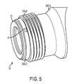
- FIG. 5is a drawing illustrating the gasket 70 engaging a spud insert in accordance with an embodiment of the present invention.
- inventions of the present inventionprovide improved systems for connecting meters and other devices to pipelines.
- the systemsinclude improved face seal gaskets having a planar annular ring portion and one or more tabs extending substantially perpendicularly from the annular ring portion.
- the annular ring portionis disposed adjacent a sealing surface on the inlet or outlet of a device to facilitate a fluid tight connection between the device and the pipeline.
- the tabsengage complementary grooves formed in the inlet or outlet portions of the device to facilitate alignment of the annular ring to the sealing surface thereon.
- the tabsmay also retain the face seal gasket adjacent the sealing surface to facilitate improved installation of the device to the pipeline.
- FIG. 1illustrates a plastic water meter 10 according to an embodiment of the present invention.
- This embodimentincludes a water meter housing assembly 20 that may enclose a metering device 40 and a strainer 50 .
- the metering device 40 and the strainer 50are positioned inside the housing assembly 20 .
- a bottom cover 60 and an o-ring 55enclose the metering device 40 and the strainer 50 within the housing assembly 20 .
- the housing assembly 20 in the illustrated embodimentincludes a top cover 21 and two connector assemblies 24 A,B.
- Each connector assembly 24 A,Bincludes a plastic spud insert 26 A,B and a metal ring 25 A,B.
- One connector assemblyfunctions as an inlet connector assembly 24 A and the other connector assembly functions as an outlet connector assembly 24 B.
- the top cover 21in the illustrate embodiment, includes an integrated inlet spud 23 A and an integrated outlet spud 23 B.
- the inlet spud 23 A and a corresponding connector assembly 26 Acombine to form the meter inlet 16 .
- the outlet spud 23 B and a corresponding connector assembly 24 Bcombine to form the meter outlet 18 .
- the top cover 21 and the two spud inserts 26 A,Bmay be made from various types of plastic or high-strength polymer materials, including styrene, polystyrene, nylon, or the like.
- the top cover 21 and the two spud inserts 26 A,Bmay be composed of glass reinforced thermoplastic. Factors that may be considered when selecting a material include working pressures of the meter, and working temperature ranges.
- the top cover 21is substantially cylindrical in shape with an integrated top face portion 22 , although those skilled in the art will recognize that the top cover 21 may take other shapes.
- the bottom of the top cover 21remains open, thus forming an aperture that leads to the interior cavity 31 of the top cover 21 .
- the top cover 21Proximate the bottom of the top cover 21 are external threads 30 , which enable the bottom cover 60 to engage to the top cover 21 .
- the top covermay flex outwards because of pressure in the system thereby causing the internal threads in the top cover to be urged against the complementary threads on the bottom cover.
- the top covermay include internal threads designed to engage external threads on the bottom cover.
- external bottom threads 30are easier to manufacture than internal bottom threads. As will be understood by those skilled in the art, forming internal threads requires an insert mold, while forming external threads does not. In some cases, an additional manufacturing step may be required to remove the internal thread mold insert, which may reduce the efficiency of the molding process.
- the top cover 21includes an integrated inlet spud 23 A, through which water enters the interior cavity 31 defined by the top cover 21 , and an integrated outlet spud 23 B, through which water exits the top cover 21 .
- the inlet spud 23 A and outlet spud 23 Bare in communication with the interior cavity 31 of the top cover 21 .
- the inlet spud 23 A and the outlet spud 23 Bare designed to receive and engage a portion of the spud inserts 26 A,B.
- both the inlet spud 23 A and the outlet spud 23 Bprotrude perpendicularly from the exterior of the top cover 21 , with the outlet spud 23 B situated approximately 180 degrees around the exterior of the top cover 21 from the inlet spud 23 A.
- the inlet spud 23 A and outlet spud 23 Bmay have a relative orientation other than 180 degrees.
- the inlet and outlet spudsmay protrude at angles other than substantially perpendicularly.
- the spuds 23 A,Bare similar to each other and have a substantially cylindrical shape.
- Each spud 23 A,Bdefines an axial bore with a proximate orifice that opens through the wall of the top cover 21 into the interior cavity 31 of the top cover 21 and a distal orifice that opens away from the top cover 21 .
- the proximate orifice and distal orifice of each spud 23 A,Bare substantially circular in shape.
- each spud 23 A,Bmay not protrude from the exterior of the top cover 21 , but may instead be an orifice in the exterior of the top cover 21 .
- the bores defined by the inlet spud 23 A and the outlet spud 23 Bare each sized to receive a spud insert 26 A,B respectively, and each spud insert 26 A,B includes an externally threaded metal ring 25 A,B.
- a purpose of the threaded metal rings 25 A,Bis to facilitate connection of the water meter to a water system, which generally utilizes metal threads for the connection to the water meter.
- the spud inserts 26 A,Bmay be substantially cylindrical in shape with a bore formed therein to allow the passage of water.
- each spud insert 26 A,Bincludes a first end proximate to the top cover 21 and a second end distal the top cover 21 .
- Proximate the second end of each spud insert 26 A,Bis an annular flange portion or rim 29 A,B that extends outwardly.
- the flange 29 A,Bincludes a surface co-planar with a planar, annular sealing surface formed on the second end of the spud insert 26 A,B.
- FIG. 4is an exploded view of the spud insert 26 A,B and a face seal gasket 70 configured to engage the spud insert 26 A,B.
- the face seal gasket 70may be injection molded from a resilient material such as rubber, EPDM, buna, silicone or other resilient material.
- the face seal gasket 70includes a substantially planar annular ring portion 72 with a plurality of tabs 74 disposed proximate the periphery of the annular ring portion 72 .
- the tabs 74have a truncated triangular shape and are oriented substantially perpendicular to the plane formed by the annular ring portion 72 .
- the tabsmay have other shapes such as square, rectangle, parallelogram, octagonal or other desired shape.
- the spud inserts 26 A,Binclude grooves 76 formed in the periphery of the annular flange 29 A,B. These grooves 76 have complementary shapes to the tabs 74 formed on the gasket 70 . In various embodiments, the tabs 74 and the grooves 76 have a “dovetail” engagement such that when engaged, the face seal gasket is held in place against the annular sealing surface 71 . Various other embodiments may use different complementary shapes.
- the tabs in the illustrated embodimentare located on the periphery of the annular ring portion 72 and the groove 76 is formed in the annular flange 29 A,B, which extends outwardly.
- the tabsmay be formed on the inner circumference of the annular ring 72 with complementary grooves formed on the inner surface of the bore of the spud inserts 26 A,B.
- the tabs/groovesare formed on both areas (e.g., inside and outside).
- the illustrated embodimentincludes three tabs 74 formed on the gasket 70 and three complementary grooves 76 formed in the spud 26 A,B; however, other embodiments may have more or less tab/groove combinations. Additionally, the tabs and grooves in the illustrated embodiment are evenly spaced around the periphery of the gasket 70 , but in other embodiments the spacing of the tabs may be asymmetrical.
- FIG. 5illustrates a gasket 70 seated on a spud insert 29 A,B.
- the annular ring portion 72 of the gasket 70is disposed on the substantially planar end surface of the spud insert 26 A,B and the tabs 74 engage the complementary grooves formed in the spud insert 26 A,B.
- tabbed gasketA benefit of various embodiments of the tabbed gasket is that the tabs aid in aligning the gasket with respect to the spud insert. Additionally, the engagement of the tabs with the spud insert may retain the gasket against the sealing surface 71 while the installer aligns the meter with the pipeline fitting during installation.
- the threaded metal rings 25 A,Bare disposed proximate the annular flange portion 29 A,B on the spud insert 26 A,B.
- the annular flange portion 29 A,Bmay also aid in positioning the threaded metal ring 25 A,B on the spud insert 26 A,B and discourage removal of the threaded metal ring 25 A,B when the spud insert 26 A,B engages the top cover 21 , as will be discussed in greater detail later.
- the spud insert 26 A,Bincludes a collar portion 28 A,B proximate the flange portion 29 A,B.
- the collar portion 28 A,Bmay be shaped to engage a complementary shaped profile of the inner surface of the threaded metal ring 25 A,B to discourage relative rotation between the threaded metal ring 25 A,B and the spud insert 26 A,B.
- the collar portion 28 A,Bincludes a hexagonal circumferential profile.
- the circumferential profile of the collar portion 28 A,Bmay define a shape having at least one linear section or facet.
- the circumferential profile of the collar portion 28 A,Bmay define a shape having a plurality of linear sections.
- the circumferential profilemay take the shape of, for example, a triangle, square, pentagon, hexagon, or octagon.
- the circumferential profile of the collar portion 28 A,Bmay be substantially oval.
- inner surface of the threaded metal ring 25 A,Bmay engage the collar portion 28 A,B by a key-fit arrangement.
- each spud insert 26 A,BExtending from the collar 28 A,B of each spud insert 26 A,B is an engagement portion 27 A,B.
- This engagement portion 27 A,Bmay have a cylindrical shape and may be sized to be positioned within the axial bore of a spud 23 A,B.
- the orifice proximate the engagement portion 27 A,B of each spud insert 26 A,Bmay be substantially circular in shape and may be substantially perpendicular to each cylindrically-shaped spud insert 26 A,B.
- the exterior diameter of the engagement portion 27 A,B of each spud insert 26 A,Bis substantially similar to the interior diameter of the axial bore of each spud 23 A,B.
- each spud insert 26 A,Bfits snugly into its associated spud 23 A,B.
- the spud insert 26 A,Bmay be secured to the respective spud 23 A,B using spin welding, solvent welding, sonic welding, or an adhesive.
- the threaded metal ring 25 A,Bmay be made from various types of metals or metal alloys, including brass, bronze, brass or bronze derivatives, stainless steel, or other similar metal materials.
- the threaded metal ring 25 A,Bis made of bronze. Factors that may be considered when selecting a material for the threaded metal ring 25 A,B include material strength and corrosion resistance.
- the top cover 21may include one spud or may include more than two spuds, in accordance with the present invention.
- each spudwould be similar in construction to the spuds disclosed above and would be shaped to engage a spud insert that may include a metal threaded ring, in accordance with the above disclosure.
- the metering device 40may be a nutating disk displacement flow meter, wobble plate meter, or other metering device known in the art.
- the metering device 40includes an inlet through which water enters the metering device 40 and an outlet through which water exits the metering device 40 .
- the metering device 40includes a nutating disk 42 mounted on a sphere 44 that is “wobbled” by the fluid flow where each “wobble” represents a finite amount of fluid transferred. It should be understood that other types of metering devices may be used in connection with the present invention.
- the strainer 50may be semi-cylindrical in shape and may be designed to be disposed between the inlet spud of the top cover 21 and the inlet of the metering device 40 .
- the strainer 50may be designed to strain foreign objects from the water before the water enters the metering device 40 .
- the metering device 40 and the strainer 50are disposed inside the top cover 21 and the bottom cover 60 encloses them within the top cover 21 .
- the bottom cover 60may be circular in shape with a top face configured to be positioned proximate to the top cover 21 and a bottom face distal to the top cover 21 .
- the top face of the bottom cover 60may include a substantially annular channel shaped and sized to engage the bottom end of the top cover 21 .
- the width of the channelmay be substantially similar to thickness of the wall of the bottom end of the top cover 21 .
- the exterior wall of the channelmay include threads that are configured to engage the external bottom threads 30 of the top cover 21 to enclose the metering device 40 and the strainer 50 within the interior cavity 31 of the top cover 21 .
- the bottom cover 60may be made from various types of plastic or high-strength polymer materials, including styrene, polystyrene, nylon, or the like.
- the bottom cover 60may be composed of glass reinforced thermoplastic. Factors that may be considered when selecting a material include working pressures of the meter, and working temperature ranges.
- the o-ring 55may be positioned in the channel to provide a seal between the top cover 21 and the cover 60 .
- the cross section of the o-ringis circular; however, other o-ring profiles may be used in connection with embodiments of the present invention.
- the face seal gasket having one or more tabsmay be used in connection with any type of pipe fitting or device having a planar sealing surface with grooves having shapes complementary to the tabs formed substantially perpendicular to the sealing surface.
- any type of pipe fitting or device having a planar sealing surface with grooves having shapes complementary to the tabs formed substantially perpendicular to the sealing surfacemay be used in connection with any type of pipe fitting or device having a planar sealing surface with grooves having shapes complementary to the tabs formed substantially perpendicular to the sealing surface.
- various embodimentshave been described as including a plastic water meter with separate connection assemblies, it should be understood that other embodiments may include meters or devices with integral inlets/outlets having similar shapes.
- a face seal gasket with tabsmay be used in conjunction with a metal water meter that includes an integral inlet and/or outlet that defines a bore, a planar sealing surface, a groove, and a set of threads.
Landscapes
- Engineering & Computer Science (AREA)
- General Engineering & Computer Science (AREA)
- Mechanical Engineering (AREA)
- Physics & Mathematics (AREA)
- Fluid Mechanics (AREA)
- General Physics & Mathematics (AREA)
- Measuring Volume Flow (AREA)
Abstract
Description
Claims (7)
Priority Applications (1)
| Application Number | Priority Date | Filing Date | Title |
|---|---|---|---|
| US12/813,925US8668206B2 (en) | 2009-06-11 | 2010-06-11 | Face seal gasket |
Applications Claiming Priority (2)
| Application Number | Priority Date | Filing Date | Title |
|---|---|---|---|
| US18619809P | 2009-06-11 | 2009-06-11 | |
| US12/813,925US8668206B2 (en) | 2009-06-11 | 2010-06-11 | Face seal gasket |
Publications (2)
| Publication Number | Publication Date |
|---|---|
| US20110005333A1 US20110005333A1 (en) | 2011-01-13 |
| US8668206B2true US8668206B2 (en) | 2014-03-11 |
Family
ID=43426441
Family Applications (1)
| Application Number | Title | Priority Date | Filing Date |
|---|---|---|---|
| US12/813,925Active2031-09-17US8668206B2 (en) | 2009-06-11 | 2010-06-11 | Face seal gasket |
Country Status (1)
| Country | Link |
|---|---|
| US (1) | US8668206B2 (en) |
Cited By (8)
| Publication number | Priority date | Publication date | Assignee | Title |
|---|---|---|---|---|
| US11336004B2 (en) | 2016-02-12 | 2022-05-17 | Mueller International, Llc | Nozzle cap multi-band antenna assembly |
| US11342656B2 (en) | 2018-12-28 | 2022-05-24 | Mueller International, Llc | Nozzle cap encapsulated antenna system |
| US11422054B2 (en)* | 2018-09-04 | 2022-08-23 | Mueller International, Llc | Hydrant cap leak detector with oriented sensor |
| US11469494B2 (en) | 2016-02-12 | 2022-10-11 | Mueller International, Llc | Nozzle cap multi-band antenna assembly |
| US11473993B2 (en) | 2019-05-31 | 2022-10-18 | Mueller International, Llc | Hydrant nozzle cap |
| US11542690B2 (en) | 2020-05-14 | 2023-01-03 | Mueller International, Llc | Hydrant nozzle cap adapter |
| US11590376B2 (en) | 2010-06-16 | 2023-02-28 | Mueller International, Llc | Infrastructure monitoring devices, systems, and methods |
| US11630021B2 (en) | 2011-08-12 | 2023-04-18 | Mueller International, Llc | Enclosure for leak detector |
Families Citing this family (5)
| Publication number | Priority date | Publication date | Assignee | Title |
|---|---|---|---|---|
| US20090232595A1 (en)* | 2008-03-13 | 2009-09-17 | Benjamin Willemstyn | Connector, Gasket and Method of Attaching The Same |
| JP5614793B2 (en)* | 2008-12-12 | 2014-10-29 | 矢崎総業株式会社 | Structure for preventing incorrect assembly of packing |
| ES2473667B2 (en)* | 2014-03-14 | 2015-04-28 | Tucai, S.A. | Duct installation device of a flexible or similar nature in faucet systems |
| US10345124B2 (en)* | 2014-03-27 | 2019-07-09 | Dieterich Standard, Inc. | Adapter for inserting wafer ring between flanges of process piping |
| US11267084B1 (en)* | 2019-01-08 | 2022-03-08 | Mitchell S. Olsen | Dipstick adapter leak repair method and kit |
Citations (33)
| Publication number | Priority date | Publication date | Assignee | Title |
|---|---|---|---|---|
| US1372178A (en) | 1919-09-12 | 1921-03-22 | William N Loving | Nut-lock |
| US1966015A (en) | 1929-04-01 | 1934-07-10 | Ignatie I Kuzovenkoff | Nut and bolt lock |
| US2128429A (en) | 1935-03-25 | 1938-08-30 | Illinois Tool Works | Locking device |
| US2260612A (en)* | 1938-02-02 | 1941-10-28 | Albert P Fall | Composite piston ring |
| US3108818A (en)* | 1959-12-14 | 1963-10-29 | Felt Products Mfg Co | Fluid transfer seal for gasket |
| US3469852A (en)* | 1965-10-23 | 1969-09-30 | Smith Blair Inc | Leak clamp for bell and spigot pipe joint |
| US3689083A (en)* | 1971-04-28 | 1972-09-05 | Sealol | Sealing ring retention device |
| US4002344A (en) | 1975-11-12 | 1977-01-11 | Smith Franklyn D | Snap-in flange seal and locator |
| US4088327A (en)* | 1977-06-22 | 1978-05-09 | General Signal Corporation | Sealing ring with tabs for holding for assembly |
| US4236736A (en)* | 1978-05-01 | 1980-12-02 | Turnbuckle Products Corporation | Hose coupling |
| US4553587A (en)* | 1983-08-15 | 1985-11-19 | Traylor Paul L | Backflush coupling and method for internal combustion engine cooling system |
| US4815747A (en)* | 1988-02-01 | 1989-03-28 | The Gorman-Rupp Company | Face type seal assembly |
| US5203477A (en)* | 1990-06-30 | 1993-04-20 | Yin Seng Lim | Closure unit for kegs |
| US5450783A (en) | 1994-03-10 | 1995-09-19 | Dana Corporation | Low emission piston ring |
| US5525226A (en)* | 1994-10-14 | 1996-06-11 | Baldwin Filters, Inc. | Preformed gasket with retaining tabs |
| US5720328A (en)* | 1996-07-31 | 1998-02-24 | Mecrom Ott U. Holey Ohg | Self-closing gas cap for automatic filling machines |
| US5904357A (en)* | 1997-07-24 | 1999-05-18 | Fleetguard, Inc. | Fluid filter seal arrangement |
| US5967674A (en) | 1998-07-15 | 1999-10-19 | Torrington Co | Selective washer and thrust bearing assembly |
| US5996810A (en)* | 1997-07-24 | 1999-12-07 | Fleetguard, Inc. | Fluid filter assembly |
| US6035906A (en)* | 1996-07-31 | 2000-03-14 | Mecrom Ott U. Holey Ohg | Self-closing gas for automatic filling machines |
| US6045693A (en)* | 1997-07-24 | 2000-04-04 | Fleetguard, Inc. | Spin-on filter assembly |
| US6167963B1 (en)* | 1998-05-08 | 2001-01-02 | Baker Hughes Incorporated | Removable non-metallic bridge plug or packer |
| US6446826B1 (en)* | 1997-02-11 | 2002-09-10 | Stant Manufacturing Inc. | Seal for filler neck closure assembly |
| US6467853B1 (en) | 2000-08-09 | 2002-10-22 | Deere & Company | Keyed anti-wear thrust washer structure |
| US6533461B2 (en) | 2001-08-14 | 2003-03-18 | The Torrington Company | Anti-reversal and anti-rotation thrust washer |
| US20050025604A1 (en) | 2003-08-01 | 2005-02-03 | Steve Slesinski | Combination lock washer and spindle bearing assembly |
| US6851726B2 (en)* | 1998-08-25 | 2005-02-08 | John T. Minemyer | Radial conduit coupling system and method |
| US20050077685A1 (en)* | 2002-06-26 | 2005-04-14 | Roddis Alan James | Mechanical seal |
| US7000995B2 (en) | 2003-04-16 | 2006-02-21 | George Allan Hagelthorn | High-integrity interlocking nut and washer system |
| US7219940B2 (en) | 2004-07-08 | 2007-05-22 | Pei-Hsiu Huang | Automobile interior removable installation frame |
| US7424909B2 (en)* | 2004-02-27 | 2008-09-16 | Smith International, Inc. | Drillable bridge plug |
| US7827987B2 (en)* | 2005-06-17 | 2010-11-09 | Nellcor Puritan Bennett Llc | Ball joint for providing flexibility to a gas delivery pathway |
| US8033549B2 (en)* | 2006-04-25 | 2011-10-11 | Scenic Precise Element Inc. | Mechanical seal |
- 2010
- 2010-06-11USUS12/813,925patent/US8668206B2/enactiveActive
Patent Citations (33)
| Publication number | Priority date | Publication date | Assignee | Title |
|---|---|---|---|---|
| US1372178A (en) | 1919-09-12 | 1921-03-22 | William N Loving | Nut-lock |
| US1966015A (en) | 1929-04-01 | 1934-07-10 | Ignatie I Kuzovenkoff | Nut and bolt lock |
| US2128429A (en) | 1935-03-25 | 1938-08-30 | Illinois Tool Works | Locking device |
| US2260612A (en)* | 1938-02-02 | 1941-10-28 | Albert P Fall | Composite piston ring |
| US3108818A (en)* | 1959-12-14 | 1963-10-29 | Felt Products Mfg Co | Fluid transfer seal for gasket |
| US3469852A (en)* | 1965-10-23 | 1969-09-30 | Smith Blair Inc | Leak clamp for bell and spigot pipe joint |
| US3689083A (en)* | 1971-04-28 | 1972-09-05 | Sealol | Sealing ring retention device |
| US4002344A (en) | 1975-11-12 | 1977-01-11 | Smith Franklyn D | Snap-in flange seal and locator |
| US4088327A (en)* | 1977-06-22 | 1978-05-09 | General Signal Corporation | Sealing ring with tabs for holding for assembly |
| US4236736A (en)* | 1978-05-01 | 1980-12-02 | Turnbuckle Products Corporation | Hose coupling |
| US4553587A (en)* | 1983-08-15 | 1985-11-19 | Traylor Paul L | Backflush coupling and method for internal combustion engine cooling system |
| US4815747A (en)* | 1988-02-01 | 1989-03-28 | The Gorman-Rupp Company | Face type seal assembly |
| US5203477A (en)* | 1990-06-30 | 1993-04-20 | Yin Seng Lim | Closure unit for kegs |
| US5450783A (en) | 1994-03-10 | 1995-09-19 | Dana Corporation | Low emission piston ring |
| US5525226A (en)* | 1994-10-14 | 1996-06-11 | Baldwin Filters, Inc. | Preformed gasket with retaining tabs |
| US5720328A (en)* | 1996-07-31 | 1998-02-24 | Mecrom Ott U. Holey Ohg | Self-closing gas cap for automatic filling machines |
| US6035906A (en)* | 1996-07-31 | 2000-03-14 | Mecrom Ott U. Holey Ohg | Self-closing gas for automatic filling machines |
| US6446826B1 (en)* | 1997-02-11 | 2002-09-10 | Stant Manufacturing Inc. | Seal for filler neck closure assembly |
| US5904357A (en)* | 1997-07-24 | 1999-05-18 | Fleetguard, Inc. | Fluid filter seal arrangement |
| US6045693A (en)* | 1997-07-24 | 2000-04-04 | Fleetguard, Inc. | Spin-on filter assembly |
| US5996810A (en)* | 1997-07-24 | 1999-12-07 | Fleetguard, Inc. | Fluid filter assembly |
| US6167963B1 (en)* | 1998-05-08 | 2001-01-02 | Baker Hughes Incorporated | Removable non-metallic bridge plug or packer |
| US5967674A (en) | 1998-07-15 | 1999-10-19 | Torrington Co | Selective washer and thrust bearing assembly |
| US6851726B2 (en)* | 1998-08-25 | 2005-02-08 | John T. Minemyer | Radial conduit coupling system and method |
| US6467853B1 (en) | 2000-08-09 | 2002-10-22 | Deere & Company | Keyed anti-wear thrust washer structure |
| US6533461B2 (en) | 2001-08-14 | 2003-03-18 | The Torrington Company | Anti-reversal and anti-rotation thrust washer |
| US20050077685A1 (en)* | 2002-06-26 | 2005-04-14 | Roddis Alan James | Mechanical seal |
| US7000995B2 (en) | 2003-04-16 | 2006-02-21 | George Allan Hagelthorn | High-integrity interlocking nut and washer system |
| US20050025604A1 (en) | 2003-08-01 | 2005-02-03 | Steve Slesinski | Combination lock washer and spindle bearing assembly |
| US7424909B2 (en)* | 2004-02-27 | 2008-09-16 | Smith International, Inc. | Drillable bridge plug |
| US7219940B2 (en) | 2004-07-08 | 2007-05-22 | Pei-Hsiu Huang | Automobile interior removable installation frame |
| US7827987B2 (en)* | 2005-06-17 | 2010-11-09 | Nellcor Puritan Bennett Llc | Ball joint for providing flexibility to a gas delivery pathway |
| US8033549B2 (en)* | 2006-04-25 | 2011-10-11 | Scenic Precise Element Inc. | Mechanical seal |
Cited By (17)
| Publication number | Priority date | Publication date | Assignee | Title |
|---|---|---|---|---|
| US11590376B2 (en) | 2010-06-16 | 2023-02-28 | Mueller International, Llc | Infrastructure monitoring devices, systems, and methods |
| US11630021B2 (en) | 2011-08-12 | 2023-04-18 | Mueller International, Llc | Enclosure for leak detector |
| US11680865B2 (en) | 2011-08-12 | 2023-06-20 | Mueller International, Llc | Leak detection in water distribution systems using acoustic signals |
| US11469494B2 (en) | 2016-02-12 | 2022-10-11 | Mueller International, Llc | Nozzle cap multi-band antenna assembly |
| US11336004B2 (en) | 2016-02-12 | 2022-05-17 | Mueller International, Llc | Nozzle cap multi-band antenna assembly |
| US11527821B2 (en) | 2016-02-12 | 2022-12-13 | Mueller International, Llc | Nozzle cap assembly |
| US12212053B2 (en) | 2016-02-12 | 2025-01-28 | Mueller International, Llc | Nozzle cap multi-band antenna assembly |
| US11837782B2 (en) | 2016-02-12 | 2023-12-05 | Mueller International, Llc | Nozzle cap assembly |
| US11652284B2 (en) | 2016-02-12 | 2023-05-16 | Mueller International, Llc | Nozzle cap assembly |
| US11692901B2 (en) | 2018-09-04 | 2023-07-04 | Mueller International, Llc | Hydrant cap leak detector with oriented sensor |
| US11422054B2 (en)* | 2018-09-04 | 2022-08-23 | Mueller International, Llc | Hydrant cap leak detector with oriented sensor |
| US11342656B2 (en) | 2018-12-28 | 2022-05-24 | Mueller International, Llc | Nozzle cap encapsulated antenna system |
| US11473993B2 (en) | 2019-05-31 | 2022-10-18 | Mueller International, Llc | Hydrant nozzle cap |
| US11624674B2 (en) | 2019-05-31 | 2023-04-11 | Mueller International, Llc | Hydrant nozzle cap with antenna |
| US12078572B2 (en) | 2019-05-31 | 2024-09-03 | Mueller International, Llc | Hydrant nozzle cap |
| US12084844B2 (en) | 2020-05-14 | 2024-09-10 | Mueller International, Llc | Hydrant nozzle cap adapter |
| US11542690B2 (en) | 2020-05-14 | 2023-01-03 | Mueller International, Llc | Hydrant nozzle cap adapter |
Also Published As
| Publication number | Publication date |
|---|---|
| US20110005333A1 (en) | 2011-01-13 |
Similar Documents
| Publication | Publication Date | Title |
|---|---|---|
| US8668206B2 (en) | Face seal gasket | |
| US8613220B2 (en) | Non-metallic enclosure with metal threads | |
| US6178816B1 (en) | Water meter | |
| US20210062924A1 (en) | Water outlet member of faucet | |
| RU2010112644A (en) | DEVICES AND METHODS OF FILTERING SYSTEMS MOUNTED ON A WATER Faucet | |
| CA2797946A1 (en) | Floating ball valve seal with bellows and c-seal | |
| RU2652856C2 (en) | Fitting for use with metal tubing | |
| US10669700B2 (en) | Wireless communication electronics storage apparatus and method of mounting the same in a dry barrel hydrant | |
| US9068421B2 (en) | Molded well head cover | |
| US20240026661A1 (en) | Universal Rough-In Valve and Manifold | |
| US12336460B2 (en) | Irrigation saddle annular seal face | |
| KR20000064478A (en) | Differential pressure, flow and level measurement system | |
| KR100634781B1 (en) | Prefabricated Pipeway for Underground Structure | |
| US20160178094A1 (en) | Threaded pipe assembly for use in a valve cartridge of a separable water faucet and method for manufacturing same | |
| KR100919282B1 (en) | Structure of anticorrosive pipe | |
| KR101135061B1 (en) | A Valve socket for preventing leakage out containing a ring shape protecting cap and a manufacturing method thereof | |
| CN221649643U (en) | Water meter | |
| KR100954126B1 (en) | Water meter | |
| KR101195484B1 (en) | Method for making pipe for incorrupting corrosion | |
| US10914048B2 (en) | Height adjustable meter/device pit | |
| KR101285706B1 (en) | Screw type snap tap with saddle | |
| JP2015161376A (en) | Packing with drop-off prevention function used for the stop cock connection | |
| WO2023106962A1 (en) | Drain valve | |
| KR101424041B1 (en) | Flowmeter and method for assembling the same | |
| WO2008022357A1 (en) | Pipe coupling |
Legal Events
| Date | Code | Title | Description |
|---|---|---|---|
| AS | Assignment | Owner name:MUELLER INTERNATIONAL, INC., GEORGIA Free format text:ASSIGNMENT OF ASSIGNORS INTEREST;ASSIGNOR:BALL, MARTY SCOTT;REEL/FRAME:025068/0820 Effective date:20100921 | |
| AS | Assignment | Owner name:MUELLER INTERNATIONAL, LLC, GEORGIA Free format text:CHANGE OF NAME;ASSIGNOR:MUELLER INTERNATIONAL, INC.;REEL/FRAME:031947/0953 Effective date:20100913 | |
| STCF | Information on status: patent grant | Free format text:PATENTED CASE | |
| AS | Assignment | Owner name:BANK OF AMERICA, N.A., AS ADMINISTRATIVE AGENT, NE Free format text:SECURITY INTEREST;ASSIGNOR:MUELLER INTERNATIONAL, LLC;REEL/FRAME:034498/0272 Effective date:20141125 | |
| AS | Assignment | Owner name:BANK OF AMERICA, N.A., AS ADMINISTRATIVE AGENT, NO Free format text:SECURITY AGREEMENT;ASSIGNOR:MUELLER INTERNATIONAL, LLC, AS GRANTOR;REEL/FRAME:034502/0219 Effective date:20141125 | |
| MAFP | Maintenance fee payment | Free format text:PAYMENT OF MAINTENANCE FEE, 4TH YEAR, LARGE ENTITY (ORIGINAL EVENT CODE: M1551) Year of fee payment:4 | |
| AS | Assignment | Owner name:MUELLER INTERNATIONAL, LLC, GEORGIA Free format text:RELEASE BY SECURED PARTY;ASSIGNOR:BANK OF AMERICA, N.A.;REEL/FRAME:046395/0444 Effective date:20180612 | |
| MAFP | Maintenance fee payment | Free format text:PAYMENT OF MAINTENANCE FEE, 8TH YEAR, LARGE ENTITY (ORIGINAL EVENT CODE: M1552); ENTITY STATUS OF PATENT OWNER: LARGE ENTITY Year of fee payment:8 | |
| MAFP | Maintenance fee payment | Free format text:PAYMENT OF MAINTENANCE FEE, 12TH YEAR, LARGE ENTITY (ORIGINAL EVENT CODE: M1553); ENTITY STATUS OF PATENT OWNER: LARGE ENTITY Year of fee payment:12 |