US8667706B2 - Rotary biomass dryer - Google Patents
Rotary biomass dryerDownload PDFInfo
- Publication number
- US8667706B2 US8667706B2US12/197,513US19751308AUS8667706B2US 8667706 B2US8667706 B2US 8667706B2US 19751308 AUS19751308 AUS 19751308AUS 8667706 B2US8667706 B2US 8667706B2
- Authority
- US
- United States
- Prior art keywords
- biomass material
- biomass
- housing
- shaft
- dryer
- Prior art date
- Legal status (The legal status is an assumption and is not a legal conclusion. Google has not performed a legal analysis and makes no representation as to the accuracy of the status listed.)
- Active, expires
Links
Images


Classifications
- F—MECHANICAL ENGINEERING; LIGHTING; HEATING; WEAPONS; BLASTING
- F26—DRYING
- F26B—DRYING SOLID MATERIALS OR OBJECTS BY REMOVING LIQUID THEREFROM
- F26B20/00—Combinations of machines or apparatus covered by two or more of groups F26B9/00 - F26B19/00
- B—PERFORMING OPERATIONS; TRANSPORTING
- B30—PRESSES
- B30B—PRESSES IN GENERAL
- B30B11/00—Presses specially adapted for forming shaped articles from material in particulate or plastic state, e.g. briquetting presses, tabletting presses
- B30B11/22—Extrusion presses; Dies therefor
- B30B11/224—Extrusion chambers
- B30B11/225—Extrusion chambers with adjustable outlet opening
- F—MECHANICAL ENGINEERING; LIGHTING; HEATING; WEAPONS; BLASTING
- F26—DRYING
- F26B—DRYING SOLID MATERIALS OR OBJECTS BY REMOVING LIQUID THEREFROM
- F26B5/00—Drying solid materials or objects by processes not involving the application of heat
- F26B5/14—Drying solid materials or objects by processes not involving the application of heat by applying pressure, e.g. wringing; by brushing; by wiping
Definitions
- Traditional biomass particulate dryersemploy external heat sources, such as gas-fired burners, to heat biomass particulates within a metal drum to a temperature sufficiently high to evaporate water from the particles. The water vapor is drawn out of the drum as steam.
- such dryerscan include paddles or a helical screw auger that continuously stirs the biomass within the drum. Alternatively, the drum may be rotated to agitate the particulates. Using such systems, it is possible to dry wet sawdust from a moisture content of up to 90%, achieving a moisture content as low as about 10%.
- Conventional dryersimplement what can be characterized as a batch drying process.
- the drum of a conventional dryeris typically loaded with a charge of wet biomass particulate material and the heat from the external source is applied until the desired moisture content of the material being dried is achieved.
- One type of biomass material that must be driedis wet sawdust, which may be produced at a lumber mill as logs are sawn into lumber, rail ties, or some other type of wood product. Lumber mills process logs on a continuous basis while in operation, so the sawdust that is a byproduct of the sawing operation is produced continually.
- biomass drum dryersare typically installed as fixed systems and are sized to handle batches of biomass material of a desired volume. Accordingly, for applications in which there is a need for a portable biomass dryer, the conventional systems are typically not practical. Also, the amount of biomass material that must be processed can sometimes be variable. For example, if the source of biomass material produces volumes of the wet material that vary substantially, it can be even less efficient to run a relatively smaller charge of the material through a conventional externally heated drum dryer when the volume to be processed is smaller than the design volume of the drum. Thus, another benefit of a continuous processing biomass dryer would be that the processing might simply be halted once the available mass of biomass material has been dried.
- drum dryersare not suitable for drying some of the waste streams produced by various industries.
- waste materials having a characteristic small particulate sizecannot normally be processed in drum dryers. These materials include sludge from waste water treatment plants, spent grains from ethanol productions facilities, wet waste paper from paper mills, waste pulp, and a host of other similar materials. It would therefore be desirable to provide a dryer that can be employed to dry such materials, so that they can be used as alternative fuels instead of being put in land fill or burned wet with the added heat provided by a secondary fuel source. Because a suitable dryer is not available, many of the producers of these waste streams are putting them in land fills at a substantial expense to themselves, and causing an adverse impact on the environment.
- biomass dryersSince the conventional biomass dryers are unable to overcome the problems noted above, it would clearly be desirable to develop a biomass dryer that operates in a substantially different manner that is able to provide continuous batch processing and is more portable. While the amount of biomass material that is to be processed is less of an issue in a continuous processing system, it would still be desirable to provide a continuous process biomass dryer that can readily be sized for almost any desired throughput rate, so that the processing capability can be generally matched to the maximum required throughput rate. The biomass dryer should also be generally portable, so that it can readily be moved to a site where there is a need for the dryer.
- a novel approachhas been developed for reducing a moisture content of a biomass material that is relatively wet.
- One aspect of this new approachis directed to an exemplary apparatus that includes a prime mover, such as an electric motor or fuel powered combustion engine, while other types of prime movers can alternatively also be used.
- the apparatusfurther includes an elongate housing extending between a proximal end and a distal end and having an inlet disposed adjacent to the proximal end for receiving the relatively wet biomass material.
- An outlet through which the biomass material passes after being dried to a substantially lower moisture contentis disposed adjacent to the distal end.
- a generally helical screw shaftis disposed within the elongate housing and is drivingly coupled to the prime mover so as to be rotated thereby about a longitudinal axis of the shaft.
- the direction of rotation of the shaftis selected so that helical screw threads formed on the shaft force the biomass material entering through the inlet to move through the housing, toward the distal end, and then out through the outlet of the housing.
- the biomass materialis compressed as it is moved through the elongate housing forcing moisture from the wet biomass material.
- friction resulting from the compression and movement of the biomass material through the housingheats the biomass material sufficiently to drive out most of the moisture remaining in the biomass material, thereby substantially drying it.
- the elongate housingincludes an adjustable section disposed adjacent to the distal end.
- This adjustable sectionincludes a plurality of adjacent longitudinally extending segments that are disposed circumferentially around the helical screw shaft and which together define a general cylindrical shape bore with an internal diameter that can be adjusted at the distal end of the elongate housing.
- the annular clearance between an interior surface of each segment and the helical screw shaftis adjusted by forcing the segments to move radially inwardly or outwardly at the distal end of the housing, thereby varying the internal diameter of the cylindrical shape formed by the segments.
- the adjustable sectionincludes a jackscrew that extends between a fixed member and a rotatable ring that extends circumferentially around the segments.
- the rotatable ringincludes a plurality of spaced-apart rotatable wheels that roll on ramps to apply a radial force against the segments that varies as the wheels roll up or down the ramps, depending on a direction in which the jackscrew is rotated.
- the varying radial forcealters the internal diameter of the cylindrical shape formed by the segments, which varies the compression of the biomass material.
- each of the segmentsincludes tabs extending radially outward and running longitudinally along opposite edges of the segment, adjacent to distal ends of the segment. Threaded fasteners couple the tabs on adjacent sections together and are tightened or loosened to achieve a desired radial compression of the plurality of segments, to variably adjust an internal diameter of a cylindrical bore shape defined by the segments.
- This embodimentfurther includes helical springs on the threaded fasteners to provide a biasing force that radially compresses the segments more when the threaded fasteners are tightened and releases the radial compression as the threaded fasteners are loosened.
- the helical screw shaftcan include a distal portion having threads that are finer and more closely spaced than threads provided on a proximal portion of the shaft. Also, the helical screw shaft can include helical threads of varying width over at least a portion of its length, and/or helical threads of differing densities along its length.
- the helical screw shaftis directly coupled to a drive shaft of the prime mover.
- the prime mover and elongate housingcan be mounted on a portable base to enable the apparatus to be portable and readily movable to a site where the apparatus is to be used for drying the wet biomass material.
- Meanscan be provided for adjusting an extent to which the biomass material is compressed before it exits through the outlet, in consideration of at least one characteristic, such as an initial moisture content of the wet biomass material that enters the inlet of the elongate housing; a particulates size of the wet biomass material entering the inlet of the elongate housing; a desired moisture content of the biomass material exiting the outlet of the elongate housing; one or more characteristics of a specific type of the wet biomass material that is to be dried with the apparatus; and, a desired temperature range for the biomass material exiting the outlet of the elongate housing.
- at least one characteristicsuch as an initial moisture content of the wet biomass material that enters the inlet of the elongate housing; a particulates size of the wet biomass material entering the inlet of the elongate housing; a desired moisture content of the biomass material exiting the outlet of the elongate housing; one or more characteristics of a specific type of the wet biomass material that is to be dried with the apparatus; and,
- the means for adjustingcan be disposed adjacent to the distal end of the elongate housing and can include a plurality of longitudinally extending segments that are circumferentially disposed around the helical screw shaft.
- the means for adjustingcan further include means for varying a radial force applied against the segments so as to vary a gap defined between the segments and the helical screw shaft.
- the inletcan be configured and the prime mover operated so as to enable a continuous processing of a stream of the wet biomass material, so long as the wet biomass material is continually supplied through the input.
- Another aspect of this novel approachis directed to a method for drying a wet biomass material to reduce its moisture content.
- the steps of the methodare generally consistent with the functions implemented by the components of the apparatus discussed above.
- the present biomass dryerhas been tested for drying waste streams comprising many of the small particulate materials that cannot be dried in conventional drum dryers and was found to be successful at reducing the moisture content to a level sufficiently low to enable these materials to be used as a high quality commercial or domestic fuel.
- the costs involved in drying small particulate materials with the present technologyhas been demonstrated to be significantly less than those associated with traditional drying methods.
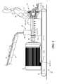
- FIG. 1is a side elevational view of an exemplary system for drying a wet biomass material and illustrates portions of a conveyor that delivers the wet biomass material into an input and of a conveyor that carries away the biomass material after it has been dried by an exemplary rotary biomass dryer;
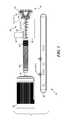
- FIG. 2is an isometric view of the rotary biomass dryer as shown in FIG. 1 ;
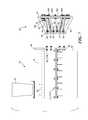
- FIG. 3is an exploded view of the rotary biomass dryer of FIG. 1 , showing further details of a helically threaded shaft that is used to move the biomass material through the dryer;
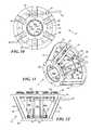
- FIG. 4is an end elevational view of the rotary biomass dryer of FIG. 1 , with the supporting base, prime mover, and helically threaded shaft removed;
- FIG. 5is a side elevational view of the rotary biomass dryer, with the same components removed as in FIG. 4 ;
- FIG. 6is an isometric view of the rotary biomass dryer, with the same components removed, as in FIG. 4 ;
- FIG. 7is an exploded side elevational view of the rotary biomass dryer, from the opposite as that shown in FIG. 5 ;
- FIG. 8illustrates a variable compression nozzle for the exemplary rotary biomass dryer
- FIG. 9is a cross-sectional view of the variable compression adjustment assembly, taken along section lines 9 - 9 of FIG. 8 ;
- FIG. 10is an elevational view of an inlet end of the variable compression nozzle
- FIG. 11is an isometric view of the variable compression nozzle
- FIG. 12is a top plan view of the variable compression nozzle
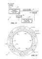
- FIG. 13is a schematic block diagram illustrating the components of an automatically controlled system for controlling the compression of the biomass material moving through the biomass dryer in response to an input signal from a sensor that is monitoring a parameter, such as the moisture of the dried biomass material;
- FIG. 14is an exemplary alternative manual adjustment variable compression nozzle for the rotary biomass dryer.
- FIG. 15is a functional block diagram of a computing device (e.g., a personal computer), which is usable for controlling the automatic variable compression nozzle of the rotary biomass dryer.
- a computing devicee.g., a personal computer
- FIG. 1illustrates an exemplary biomass drying system 20 in which a conveyor 22 is used to supply a wet biomass material 24 to an input hopper 26 of a rotary biomass dryer 28 .
- a base frame 30is employed to support a prime mover 32 , which in this example is an electric motor, as well as rotary biomass dryer 28 .
- a plurality of threaded fasteners 34are used to mount the prime mover to the base frame.
- the base frameis strong, but relatively lightweight and is sufficiently portable so that it can readily be transported to a site where there is a need for drying wet biomass material.
- the biomass drying systemcan be used to dry wet sawdust produced by a lumber mill.
- the biomass drying systemcan be scaled up or down in size and capacity to handle various production rates for drying wet biomass material. Thus, a smaller biomass drying system might be transported to a site where a portable sawmill is being used, to enable drying of the sawdust produced by the sawmill.
- the biomass drying system shown in FIG. 1includes an electric motor for prime mover 32
- prime mover 32other types might instead be used, such as an internal combustion engine (gas or diesel, or other fuel), or other types of fuel burning engines or power sources.
- the prime movercan thus be selected to burn available fuel at the site, and might, for example, burn sawdust to produce steam, to enable a steam engine to serve as the prime mover.
- FIGS. 2-7illustrate further details and views of exemplary rotary biomass dryer 28
- FIGS. 8-12illustrate different views and details of a variable compression nozzle 44 , which is used for final compression and heating of the biomass material and which can be adjusted to achieve a desired parameter or characteristic in regard to the drier biomass material that is produced as a result of compression and frictional heating of the wet biomass material passing through the rotary biomass dryer.
- an auger shaft 36having variable width helical threads 70 a on a proximal portion of its length and a section of more closely spaced-apart helical threads 70 b (i.e., a section of the auger shaft having a higher density of threads, or more threads per inch) on its distal end.
- the auger shaftis rotatably driven by prime mover 32 .
- Helical threads 70 a of auger shaft 36normally extend through the portion of rotary biomass dryer 28 that includes a lower housing 38 and an upper housing 40 .
- a bore through the housingis defined by upper housing 40 and a lower bore portion 56 .
- the upper and lower housing(including lower bore portion 56 ) are coupled together around the auger shaft by a plurality of threaded fasteners 42 .
- Variable compression nozzle 44is coupled to the outlet of the upper and lower housing, using threaded fasteners 46 , so that the section of the auger shaft with the more closely spaced-apart helical threads 70 b are normally disposed within the portion of the bore defined by the variable compression nozzle.
- the wet biomass material that enters input hopper 26falls through an opening 58 that is formed in upper housing 40 ( FIG. 7 ).
- This materialis conveyed through the rotary biomass dryer by the helical threads on auger shaft 36 and after passing through variable compression nozzle 44 , passes out through the outlet of the dryer as relatively drier biomass material 48 .
- the increasing width of the helical threads in the section of the auger shaft having variable width helical threads 70 aboth compresses the particles comprising the biomass material and heats the biomass material due to friction between the material and both the threads and the interior of the bore.
- the compression and heat of friction produced in the rotary biomass dryerreduce the moisture content of the biomass material passing through the outlet by 30% to 40%. At least some of the moisture included in the wet biomass material leaves orifices formed in the housing of the rotary biomass dryer as liquid water, while much of the moisture is evaporated, forming clouds of steam 54 , as shown in FIG. 1 , due to the heating that occurs as a result of the friction as the biomass material is advanced through the bore of the dryer by the auger shaft.
- the temperature of the dry biomass materialcan be in the range from about 212° F. to about 250° F.
- the dry biomass materialis carried away on a conveyor 50 in exemplary biomass drying system 20 , which is shown in FIG. 1 .
- a compression adjustor 52can be rotated or otherwise moved so as to adjust the level of compression applied by variable compression nozzle 44 , and to thus achieve a desired parameter in dry biomass material 48 .
- a desired parameter in dry biomass material 48For example, it may be desirable to control the moisture content of the dry biomass material to a specific level, so that the dry material can be more readily pressed into pellets for pellet wood stove fuel, or pellets for livestock bedding, or into pressed logs that can be burned in a fireplace.
- Each of these usesmay require a different level of moisture content in the dry biomass material being produced by the rotary biomass dryer.
- the desired characteristic or parameter of the dry biomass material produced by the dryermay relate to a desired density or a desired friability (or compressed state) of the dry biomass material.
- the characteristics of the dried biomass material or of the wet biomass materialcan also be a basis for determining the extent of the compression applied to the materials.
- the following characteristicscan affect the compression applied: an initial moisture content of the wet biomass material that enters the inlet of the elongate housing; a size of particulates comprising the wet biomass material entering the inlet of the elongate housing; a desired moisture content of the dried biomass material exiting the outlet of the elongate housing; one or more characteristics of a specific type of the wet biomass material that is to be dried with the apparatus; and, a desired temperature range for the dried biomass material exiting the outlet.
- annular ring 90disposed at the proximal end of variable compression nozzle 44 is attached by a plurality of threaded fasteners 46 (machine bolts and mating nuts) to arcuate flanges 92 and 94 , which are respectively welded or otherwise attached to the distal ends of upper housing 40 and lower bore portion 56 of lower housing 38 .
- Annular ring 90includes a central round opening (not specifically indicated by a reference number) having a size that matches that of the bore formed in the housing.
- a plurality of circumferentially spaced-apart struts 84are welded (or otherwise attached) to the other side of annular ring 90 and extend distally and outwardly to attach to the proximal face of an annular ring 64 .
- a rotatable ring 66is disposed within annular ring 64 and is rotated when the compression provided by the compression nozzle is being changed.
- FIGS. 8-12are particularly helpful in understanding the configuration and operation of compression nozzle 44 .
- the compression nozzleincludes eight segments 80 a - 80 f that each include two longitudinally extending tabs 86 attached to their outer surface and adjacent to annular ring 90 .
- Each of a plurality of threaded fasteners 82extend through orifices formed in the tabs and in strut 84 , so that the proximal ends of segments 80 a - 80 f are pivotally attached to and supported by the struts.
- the longitudinally extending edges of adjacent segments 80 a - 80 foverlap, generally as shown in FIG. 10 .
- FIG. 9The cross-sectional view shown in FIG. 9 will make clear how a plurality of circumferentially spaced-apart rotatable wheels 100 are mounted on axles 102 that are attached to an inner annular ring 106 , which is free to rotate about the bore defined between segments 80 a - 80 f , along with rotatable ring 66 , which retains the inner annular ring.
- a pin 110 that engages inner annular ring 106extends from a captive bearing mount 62 through an orifice in rotatable ring 66 .
- the distal end of compression adjustor 52is captured within captive bearing mount 62 , but is free to rotate within it.
- Compression adjustor 52is threaded along at least a portion of its length and its threads engage a threaded ring 60 that is mounted on annular ring 64 by a pin 108 (also see FIG. 10 to understand the disposition of compression adjustor 52 , captive bearing mount 62 , and threaded ring 60 ).
- Rotation of compression adjustor 52which acts as a jackscrew, varies the distance between captive bearing mount 62 and threaded ring 60 , causing rotation of inner annular ring 106 about the central bore of variable compression nozzle 44 .
- wheels 100roll along ramps 104 , so that as the wheels roll up the ramps, an inner surface of each ramp is forced against an outer surface of an adjacent one of segments 80 a - 80 f , displacing the inner surface of the distal end of the segment radially inward and closer to the end of the auger shaft.
- This inward displacement of the segmentsincreases the compression of the biomass material passing through the bore of the rotary biomass dryer where more closely spaced-apart helical threads 70 b are disposed, increasing the extent to which moisture is forced from the biomass material and increasing the frictional force that heats the biomass material.
- wheels 100roll down ramps 104 , and segments 80 a - 80 f are allowed to expand radially outward, decreasing the compression applied to the biomass material and reducing the extent to which moisture is forced from and evaporated to dry the biomass material.
- compression adjustor 52can be carried out manually by simply providing an appropriate end on the compression adjustor that can be engaged by a rotatable tool, such as a square or hex shaped end that is engaged by a wrench or socket and then using the tool to rotate the compression adjustor in the direction appropriate to achieve a desired increase or decrease of the compression provided by variable compression nozzle 44 .
- a power rotary drive toolsuch as a power drill, might also be used for this purpose.
- other mechanisms for adjusting or varying the amount of compression applied to the biomass material being conveyed through the rotary biomass dryercan alternatively be used. One such alternative mechanism is discussed below.
- FIG. 13illustrates a functional block diagram of an automated compression control system 120 for automatically controlling the compression applied by rotary biomass dryer 20 using variable compression nozzle 44 .
- a sensor 122monitors a desired parameter or characteristic of the dried biomass material being output from rotary biomass dryer 20 , producing either an analog or digital output signal that is indicative of a level of that parameter or characteristic in the dried biomass material.
- the output signal from the sensoris input to a computing device or other controller 124 .
- the computing device or other controllerBased upon a comparison the detected level of the parameter or characteristic of the dried biomass material with a desired level that was input, the computing device or other controller produces an output signal that is used to energize an actuator 126 to controllably rotate compression controller 52 in an appropriate direction and to an appropriate extent, to increase or decrease the amount of compression being applied to the biomass material by the rotary biomass dryer, so as to achieve the desired level of the parameter or characteristic of the dried biomass material.
- the actuatorcan be a small prime mover, such as an electric motor, stepping motor, hydraulic actuator, or other suitable controllable device designed to rotate the compression controller in an appropriate direction and by an appropriate amount to achieve the level of the parameter or desired characteristic of the dried biomass material.
- the compression controllercan simply be pushed/pulled if it is not threaded, so that it slides through a bearing where threaded ring 60 is disposed, and thereby causes the rotation of inner annular ring 106 to vary the compression applied to the biomass material.
- Sensor 122will be selected to detect the level of the desired parameter or characteristic of the dried biomass material.
- the parameter being controlledis the moisture content of the dried biomass material
- sensor 122will be a moisture sensor, e.g., a sensor that determines the conductance of the dried biomass material as an indication of its moisture content.
- the parameter to be sensedis density, a densitometer can be used for sensor 122 .
- any other parameter or characteristic to be controlledwill dictate the appropriate type of sensor 122 to be used to monitor the condition of the dried biomass material.
- Variable compression nozzle 140employs controls at an extent to which the distal ends of a plurality of longitudinally extending segments 142 a - 142 f are forced radially inward to increase the compression applied to biomass material moving through the distal portion of the bore in rotary biomass dryer 20 .
- Each segment 142 a - 142 fis about the same length as segments 80 a - 80 f from variable compression nozzle 44 , but includes a stiffener backbone 144 that extends longitudinally (i.e., into the Figure as shown) toward annular ring 90 .
- Edges of adjacent segments 142 a - 142 feach include outwardly extending tabs 146 .
- Threaded fasteners 148join the adjacent tabs on adjacent pairs of the segments.
- Also provided on each end of threaded fasteners 148are helical coil springs 150 . As threaded fasteners 148 are uniformly tightened, they compress helical coil springs 150 , applying a force on tabs 146 that draws the edges of the adjacent segments together, tending to reduce gaps 152 that are formed between the edges of each pair of adjacent segments.
- variable compression nozzle 140While it might be possible to apply an automated control of variable compression nozzle 140 using a plurality of actuators that are applied to each threaded fastener 148 , such an approach is considered less efficient, compared to the jackscrew-type adjustment of variable compression nozzle 44 .
- variable compression nozzle 140is included, since it at least represents an alternative variable compression nozzle, which was in fact used on an earlier exemplary embodiment of the rotary biomass dryer.
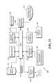
- FIG. 15illustrates details of a functional block diagram for a computing device 200 .
- the computing devicecan be a typical personal computer, but can take other forms in which a logic or hardwired device carries the automated control of the variable compression nozzle to achieve a desired parameter, such as a desired moisture content of the dried biomass material that is produced by the exemplary rotary biomass dryer discussed above, in response to an input signal from sensor 122 .
- a processor 212is employed for executing machine instructions that are stored in a memory 216 .
- the machine instructionsmay be transferred to memory 216 from a data store 218 over a generally conventional bus 214 , or may be provided on some other form of memory media, such as a digital versatile disk (DVD), a compact disk read only memory (CD-ROM), or other non-volatile memory device.
- a digital versatile diskDVD
- CD-ROMcompact disk read only memory
- An example of such a memory mediumis illustrated by a CD-ROM 234 .
- Processor 212 , memory 216 , and data store 218which may be one or more hard drive disks or other non-volatile memory, are all connected in communication with each other via bus 214 .
- the machine instructions control processor 212so that it responds to a signal input from sensor 122 and adjusts the variable compression nozzle as necessary to either increase or decrease the extent of compression applied to the biomass material that is output from rotary biomass dryer 28 .
- the machine instructions in the memoryare readable by the processor and executed by it to carry out the variable compression nozzle control function and other functions that may be useful in automating the process, such as controlling the conveyors providing the wet biomass material to the input of the biomass dryer and conveying the dry biomass material from the outlet of the variable compression nozzle.
- a network interface 228that can be coupled to the Internet or another network 230 , an input/output interface 220 (which may include one or more data ports such as any of a serial port, a universal serial bus (USB) port, a Firewire (IEEE 1394) port, a parallel port, a personal system/2 (PS/2) port, etc.), and a display interface or adaptor 222 .
- an input/output interface 220which may include one or more data ports such as any of a serial port, a universal serial bus (USB) port, a Firewire (IEEE 1394) port, a parallel port, a personal system/2 (PS/2) port, etc.
- PS/2personal system/2
- Any one or more of a number of different input devices 224such as a keyboard, mouse or other pointing device, trackball, touch screen input, etc., are connected to I/O interface 220 .
- a monitor or other display device 226is coupled to display interface 222 , so that a user can view graphics and text produced by the computing system as a result of executing the machine instructions, both in regard to an operating system and any applications being executed by the computing system, enabling a user to interact with the system.
- An optical drive 232is included for reading (and optionally writing to) CD-ROM 234 , or some other form of optical memory medium.
- the input signal from sensor 122can be a digital signal or an analog signal indicating the state of the biomass material that is output from the rotary biomass dryer. If an analog signal is produced by the sensor, it may be necessary to convert the analog level to a digital value, so that the processor can determine if the current value of the parameter, such as the moisture content in the dried biomass material is less than or greater than a desired value. If the biomass material that leaves the outlet is too wet, the processor can produce a control signal that controls actuator 126 , causing it to increase the level of compression applied by the variable compression nozzle, and conversely, if drier than necessary, can reduce the level of compression using the actuator.
- a different type of sensor 122can be employed to detect other parameters of the dried biomass material, such as its density, friability, etc., which can be controlled to achieve a desired value by the processor automatically adjusting the degree of compression of the biomass material applied by the variable compression nozzle.
Landscapes
- Engineering & Computer Science (AREA)
- Mechanical Engineering (AREA)
- General Engineering & Computer Science (AREA)
- Health & Medical Sciences (AREA)
- Life Sciences & Earth Sciences (AREA)
- Molecular Biology (AREA)
- Solid Fuels And Fuel-Associated Substances (AREA)
Abstract
Description
Claims (9)
Priority Applications (2)
| Application Number | Priority Date | Filing Date | Title |
|---|---|---|---|
| US12/197,513US8667706B2 (en) | 2008-08-25 | 2008-08-25 | Rotary biomass dryer |
| US14/161,892US9140495B2 (en) | 2008-08-25 | 2014-01-23 | Rotary biomass dryer |
Applications Claiming Priority (1)
| Application Number | Priority Date | Filing Date | Title |
|---|---|---|---|
| US12/197,513US8667706B2 (en) | 2008-08-25 | 2008-08-25 | Rotary biomass dryer |
Related Child Applications (1)
| Application Number | Title | Priority Date | Filing Date |
|---|---|---|---|
| US14/161,892DivisionUS9140495B2 (en) | 2008-08-25 | 2014-01-23 | Rotary biomass dryer |
Publications (2)
| Publication Number | Publication Date |
|---|---|
| US20100043246A1 US20100043246A1 (en) | 2010-02-25 |
| US8667706B2true US8667706B2 (en) | 2014-03-11 |
Family
ID=41694986
Family Applications (2)
| Application Number | Title | Priority Date | Filing Date |
|---|---|---|---|
| US12/197,513Active2031-02-17US8667706B2 (en) | 2008-08-25 | 2008-08-25 | Rotary biomass dryer |
| US14/161,892Active - Reinstated2028-12-22US9140495B2 (en) | 2008-08-25 | 2014-01-23 | Rotary biomass dryer |
Family Applications After (1)
| Application Number | Title | Priority Date | Filing Date |
|---|---|---|---|
| US14/161,892Active - Reinstated2028-12-22US9140495B2 (en) | 2008-08-25 | 2014-01-23 | Rotary biomass dryer |
Country Status (1)
| Country | Link |
|---|---|
| US (2) | US8667706B2 (en) |
Cited By (6)
| Publication number | Priority date | Publication date | Assignee | Title |
|---|---|---|---|---|
| US20140137421A1 (en)* | 2008-08-25 | 2014-05-22 | Enginuity Worldwide, LLC | Rotary biomass dryer |
| WO2016127171A1 (en) | 2015-02-06 | 2016-08-11 | Enginuity Worldwide, LLC | Method to enhance grain processing and digestibility |
| WO2016176365A1 (en) | 2015-04-27 | 2016-11-03 | Enginuity Worldwide, LLC | Rapid compression apparatus for treatment of moisture-containing bio-material |
| WO2017011669A1 (en) | 2015-07-14 | 2017-01-19 | Enginuity Worldwide, LLC | Process for producing bio-products from biomass using rotary compression unit |
| US20180119020A1 (en)* | 2016-11-01 | 2018-05-03 | Enginuity Worldwide, LLC | System for producing biocoal and biochar using a rotary compression unit |
| US10093878B2 (en) | 2015-03-10 | 2018-10-09 | Enginuity Worldwide, Llc. | Biomass apparatus and method with pre-treatment and reflux condenser |
Families Citing this family (21)
| Publication number | Priority date | Publication date | Assignee | Title |
|---|---|---|---|---|
| US8832964B2 (en)* | 2010-06-02 | 2014-09-16 | Robert J. Foxen | System and method for recovering turpentine during wood material processing |
| GB2492790B (en)* | 2011-07-12 | 2013-08-07 | New Earth Advanced Thermal Technologies Ltd | Feed compactor variable orifice outlet |
| US8844157B2 (en) | 2011-09-23 | 2014-09-30 | Agl Resources Inc. | Biosolids drying system and method |
| EP2636977A1 (en)* | 2012-03-07 | 2013-09-11 | Kurt Hofer | Method for reducing the moisture content of a bulk raw material, preferably an organic raw material |
| KR101970526B1 (en)* | 2012-04-26 | 2019-04-19 | 엘지전자 주식회사 | Mobile terminal |
| US8756830B2 (en)* | 2012-10-11 | 2014-06-24 | Eastman Kodak Company | Dryer transporting moistened medium through heating liquid |
| US10012441B2 (en)* | 2014-04-01 | 2018-07-03 | Albert A. Mardikian | Waste management system and method |
| CA2969840A1 (en) | 2014-12-09 | 2016-06-16 | Sweetwater Energy, Inc. | Rapid pretreatment |
| US10363561B2 (en) | 2016-01-19 | 2019-07-30 | Albert Mardikian | Apparatus for shredding of waste |
| US10071405B2 (en) | 2016-01-19 | 2018-09-11 | Albert Mardikian | Apparatus for thermal treatment of organic waste |
| US10919249B2 (en) | 2016-02-19 | 2021-02-16 | Albert Mardikian | Apparatus for pressing and dehydrating of waste |
| CA3011621A1 (en)* | 2016-02-19 | 2017-08-24 | Albert Mardikian | Systems for processing waste to form useable products and methods thereof |
| CN109154472A (en)* | 2016-02-19 | 2019-01-04 | 阿尔伯特·马迪凯恩 | System and method for processing waste to form usable products |
| CA3022168C (en)* | 2016-05-12 | 2023-08-29 | The Gsi Group Llc | Agricultural dryer with mixed-flow fan |
| CA3053773A1 (en) | 2017-02-16 | 2018-08-23 | Sweetwater Energy, Inc. | High pressure zone formation for pretreatment |
| CN107962806A (en)* | 2017-12-08 | 2018-04-27 | 梧州市国佳节能科技有限公司 | Biological substance fuel forming machine |
| CN110421891B (en)* | 2019-07-28 | 2020-04-28 | 南京汉尔斯生物科技有限公司 | Auxiliary blanking device for sludge treatment and forming mechanism thereof |
| CN112254147A (en)* | 2019-12-06 | 2021-01-22 | 苗广传 | Straw recovery unit for agricultural production |
| WO2021133733A1 (en) | 2019-12-22 | 2021-07-01 | Sweetwater Energy, Inc. | Methods of making specialized lignin and lignin products from biomass |
| CN114198988B (en)* | 2021-12-29 | 2022-10-25 | 双胞胎(集团)股份有限公司 | A dewatering system for domestic animal feed ingredient |
| CN116625093A (en)* | 2023-05-16 | 2023-08-22 | 铜陵市汇丰高效膨润土有限公司 | Quick spin flash drying equipment is used in bentonite processing |
Citations (104)
| Publication number | Priority date | Publication date | Assignee | Title |
|---|---|---|---|---|
| US3222797A (en)* | 1961-02-17 | 1965-12-14 | Int Basic Economy Corp | Methods for the removal of moisture from polymeric materials |
| US3400465A (en)* | 1967-01-26 | 1968-09-10 | Ireland James D | Permeable bed drying process |
| US3757426A (en)* | 1969-07-07 | 1973-09-11 | R Candor | Liquid removing method |
| US3831290A (en)* | 1971-11-11 | 1974-08-27 | Monsanto Co | Method and apparatus for processing high nitrile polymers |
| USRE29782E (en)* | 1969-07-02 | 1978-09-26 | Union Carbide Corporation | Cyclic oxygenation of BOD-containing water |
| US4255129A (en)* | 1979-07-11 | 1981-03-10 | Thomas N. DePew | Apparatus and method for processing organic materials into more useful states |
| US4427453A (en)* | 1980-02-23 | 1984-01-24 | Reitter Franz Johann | Two stage continuous hydrolysis of plant biomass to sugars |
| US4492171A (en)* | 1983-12-12 | 1985-01-08 | Brashears David F | Solid fuel burner |
| US4597772A (en)* | 1984-09-20 | 1986-07-01 | Wright-Malta Corporation | Fixed kiln with rotor steam gasifier |
| US4616572A (en)* | 1983-10-17 | 1986-10-14 | Franz Berthiller | Biomass incinerator |
| US4759300A (en) | 1987-10-22 | 1988-07-26 | Balboa Pacific Corporation | Method and apparatus for the pyrolysis of waste products |
| US4848249A (en)* | 1987-11-30 | 1989-07-18 | Texas A&M University | System and process for conversion of biomass into usable energy |
| US5138957A (en)* | 1991-05-15 | 1992-08-18 | Biotherm Energy Systems, Inc. | Hot gas generation system for producing combustible gases for a burner from particulate solid organic biomass material |
| US5171592A (en)* | 1990-03-02 | 1992-12-15 | Afex Corporation | Biomass refining process |
| US5271162A (en)* | 1990-05-18 | 1993-12-21 | Sc Technology Ag | Process for the emission-free drying of a substance in a drying drum |
| US5279234A (en)* | 1992-10-05 | 1994-01-18 | Chiptec Wood Energy Systems | Controlled clean-emission biomass gasification heating system/method |
| FR2694218A1 (en)* | 1992-07-30 | 1994-02-04 | Sundgau Sarl Atelier Const Ele | Continuous treatment of radioactive sludge - by crushing and heating to form dry granules with separate treatment of condensate and gases |
| US5341637A (en)* | 1992-12-22 | 1994-08-30 | Hamrick Joseph T | System for burning biomass to fuel a gas turbine |
| US5370999A (en)* | 1992-12-17 | 1994-12-06 | Colorado State University Research Foundation | Treatment of fibrous lignocellulosic biomass by high shear forces in a turbulent couette flow to make the biomass more susceptible to hydrolysis |
| US5578547A (en)* | 1994-05-26 | 1996-11-26 | Aero-Terra-Aqua Technologies Corp. | Bead for removing dissolved metal contaminants |
| US5602071A (en)* | 1994-05-26 | 1997-02-11 | Aero-Terra-Aqua Technologies Corporation | Bead for removing dissolved metal contaminants |
| US5653883A (en)* | 1994-03-14 | 1997-08-05 | Newman; William A. | Stirred tank biological activated carbon adsorption-desorption process |
| US5666890A (en)* | 1994-06-22 | 1997-09-16 | Craig; Joe D. | Biomass gasification system and method |
| US5682683A (en)* | 1993-08-10 | 1997-11-04 | Franz Haimer | Process and device for pressing biomass |
| US5705035A (en) | 1993-10-28 | 1998-01-06 | Texaco, Inc. | Tire liquefying process reactor discharge system and method |
| US5720165A (en)* | 1995-09-21 | 1998-02-24 | Bioten Gp | System for burning biomass to produce hot gas |
| US5728447A (en)* | 1993-07-20 | 1998-03-17 | Haimer; Franz | Pressed body prepared from plant material by pelletization and device for preparing same |
| US6043392A (en)* | 1997-06-30 | 2000-03-28 | Texas A&M University System | Method for conversion of biomass to chemicals and fuels |
| US6048374A (en)* | 1997-08-18 | 2000-04-11 | Green; Alex E. S. | Process and device for pyrolysis of feedstock |
| JP2000230709A (en)* | 1999-02-05 | 2000-08-22 | Plantec Inc | Multi-fuel fired furnace for sludge having rotary sludge cutting device |
| US6171853B1 (en)* | 1998-08-10 | 2001-01-09 | Byung Joon Kim | Method and apparatus for treating volatile organic compound (VOC) and odor in air emissions |
| JP2001300595A (en)* | 2000-04-24 | 2001-10-30 | Shimadzu Corp | Water treatment system |
| US6350608B1 (en)* | 1999-12-22 | 2002-02-26 | Ajt & Associates, Inc. | Biological digestion of animal carcasses |
| US6381963B1 (en)* | 2000-11-02 | 2002-05-07 | Ethopower Corporation Inc. | High temperature intermittently sealable refractory tile and controlled air continuous gasifiers manufactured therewith |
| US6398921B1 (en) | 1995-03-15 | 2002-06-04 | Microgas Corporation | Process and system for wastewater solids gasification and vitrification |
| US20020069798A1 (en)* | 2000-09-14 | 2002-06-13 | Aguadas Ellis Charles W. | Method and apparatus for generating and utilizing combustible gas |
| US20020159929A1 (en)* | 2000-02-29 | 2002-10-31 | Shozo Kaneko | Biomass gasifycation furnace and system for methanol synthesis using gas produced by gasifying biomass |
| US20030024686A1 (en)* | 2001-07-12 | 2003-02-06 | Ouellette Joseph P. | Biomass heating system |
| US20040025715A1 (en)* | 2000-08-22 | 2004-02-12 | Torben Bonde | Concept for slurry separation and biogas production |
| US20040055303A1 (en)* | 1998-11-10 | 2004-03-25 | Ormat Industries Ltd. | Method of and apparatus for producing power in remote locations |
| US20040060293A1 (en)* | 1998-11-10 | 2004-04-01 | Ormat Industries Ltd. | Method of and apparatus for producing power in remote locations |
| US20040138445A1 (en)* | 2001-07-10 | 2004-07-15 | Thorre Doug Van | Process for obtaining bio-functional fractions from biomass |
| US20040261670A1 (en)* | 2003-06-26 | 2004-12-30 | Raymond Dueck | Biomass gasification system |
| US6855180B1 (en)* | 1999-06-23 | 2005-02-15 | Rm Materiais Refratarios Ltda. | Catalytic cellulignin fuel |
| US20050054086A1 (en)* | 2003-09-04 | 2005-03-10 | Heiner Ophardt | Automated biological growth and dispensing system |
| US6878212B1 (en)* | 1999-06-23 | 2005-04-12 | Rm Materials Refratarios Ltda | Apparatus and process for pre-hydrolysis of biomass |
| US20050109603A1 (en)* | 2003-11-21 | 2005-05-26 | Graham Robert G. | Pyrolyzing gasification system and method of use |
| US20060112639A1 (en)* | 2003-11-29 | 2006-06-01 | Nick Peter A | Process for pyrolytic heat recovery enhanced with gasification of organic material |
| US20060225424A1 (en)* | 2005-04-12 | 2006-10-12 | Zilkha Biomass Energy Llc | Integrated Biomass Energy System |
| US7144558B2 (en) | 2004-07-01 | 2006-12-05 | Biogas Technologies, Inc. | Wood gasification apparatus |
| US20070029252A1 (en)* | 2005-04-12 | 2007-02-08 | Dunson James B Jr | System and process for biomass treatment |
| US20070209480A1 (en)* | 2006-03-13 | 2007-09-13 | Michigan Technological University | Production of iron using environmentally-benign renewable or recycled reducing agents |
| US20080023397A1 (en)* | 2005-08-18 | 2008-01-31 | New Bio E. Systems, Incorporated | Biomass treatment of organic waste or water waste |
| US20080029233A1 (en)* | 2006-08-03 | 2008-02-07 | Purevision Technology, Inc. | Moving bed biomass fractionation system and method |
| US20080131830A1 (en)* | 2006-12-05 | 2008-06-05 | Nix Martin E | Use of renewable energy like solar, wind, geothermal, biomass, and hydropower for manufacturing combustion air for a fossil fuel burner and firebox |
| US20080138862A1 (en)* | 2004-11-29 | 2008-06-12 | Elsam Engineering A/S | Enzymatic Hydrolysis of Biomasses Having a High Dry Matter (Dm) Content |
| US20080184709A1 (en)* | 2007-02-07 | 2008-08-07 | Rowell Dean W | Turbine power generation using lignin-based fuel |
| US20080202993A1 (en)* | 2007-01-22 | 2008-08-28 | Clean Earth Solutions, Inc. | Method and apparatus for treating solid waste |
| US20080253956A1 (en)* | 2006-08-25 | 2008-10-16 | Rossi Robert A | Process and system for producing commercial quality carbon dioxide from high solids lime mud |
| US20080307703A1 (en)* | 2007-04-24 | 2008-12-18 | Dietenberger Mark A | Method and apparatus to protect synthesis gas via flash pyrolysis and gasification in a molten liquid |
| US20090000301A1 (en)* | 2007-06-27 | 2009-01-01 | Graham Robert G | Ceramic intermittently sealable refractory tile and controlled air continuous gasifiers |
| US20090007484A1 (en)* | 2007-02-23 | 2009-01-08 | Smith David G | Apparatus and process for converting biomass feed materials into reusable carbonaceous and hydrocarbon products |
| US20090053800A1 (en)* | 2007-08-22 | 2009-02-26 | Julie Friend | Biomass Treatment Apparatus |
| US20090053777A1 (en)* | 2007-08-22 | 2009-02-26 | Susan Marie Hennessey | Process For Concentrated Biomass Saccharification |
| US20090050000A1 (en)* | 1994-02-02 | 2009-02-26 | Norman Murray Stephens | Biomass pressure liquid recovery system |
| US20090050134A1 (en)* | 2007-08-22 | 2009-02-26 | Julie Friend | Biomass Treatment Method |
| US20090056205A1 (en)* | 2007-08-28 | 2009-03-05 | Stephane Gauthier | Plant biomass solid fuel |
| US20090056208A1 (en)* | 2007-08-28 | 2009-03-05 | Stephane Gauthier | Cubing machine for manufacture of plant biomass solid fuel |
| US20090056206A1 (en)* | 2007-08-28 | 2009-03-05 | Stephane Gauthier | Method for manufacture of plant biomass solid fuel |
| US20090064569A1 (en)* | 2007-09-06 | 2009-03-12 | Abhay Kumar Khater | Pelletising of Fibrous Combustible Material at Variable Pressure and Variable Temperature |
| US20090130740A1 (en)* | 2003-09-04 | 2009-05-21 | Heiner Ophardt | Automated biological growth and dispensing system |
| US20090188160A1 (en)* | 2008-01-30 | 2009-07-30 | Henry Liu | Method and Device to Compact Biomass |
| US20090193679A1 (en)* | 2006-06-29 | 2009-08-06 | Guyomarc H Raymond | Method and system for roasting a biomass feedstock |
| US20090199747A1 (en)* | 2008-02-08 | 2009-08-13 | Wood-Mizer Products, Inc. | Biomass burner system |
| US20090205363A1 (en)* | 2007-08-15 | 2009-08-20 | Ronald De Strulle | Environmentally-neutral processing with condensed phase cryogenic fluids |
| US20090223612A1 (en)* | 2007-11-16 | 2009-09-10 | Mcknight James K | Powdered fuels and powdered fuel dispersions |
| US20090223859A1 (en)* | 2008-03-08 | 2009-09-10 | Jurgen Buchert | Method and apparatus for thermal processing of biomass |
| US20090249685A1 (en)* | 2008-03-28 | 2009-10-08 | Flowers Troy D | Closed loop biomass energy system |
| US20090305355A1 (en)* | 2006-05-26 | 2009-12-10 | Elsam Kraft A/S | Method for Syngas-Production from Liquefied Biomass |
| US20090313847A1 (en)* | 2008-06-19 | 2009-12-24 | Horst Weigelt | Device and method for obtaining energy carriers from moist biomass |
| US20100000224A1 (en)* | 2007-02-07 | 2010-01-07 | A.G.T. Srl | Gasification plant |
| US7658776B1 (en)* | 1999-08-25 | 2010-02-09 | Pearson Larry E | Biomass reactor for producing gas |
| US20100038082A1 (en)* | 2008-08-17 | 2010-02-18 | Zubrin Robert M | Portable renewable energy system for enhanced oil recovery (preseor) using biomass having net negative co2 emissions and for generating electricity having zero co2 emissions |
| US20100040527A1 (en)* | 2008-08-18 | 2010-02-18 | Randhava Sarabjit S | Process for producing ammonia from biomass |
| US20100043246A1 (en)* | 2008-08-25 | 2010-02-25 | Smith David N | Rotary biomass dryer |
| US20100071369A1 (en)* | 2006-12-16 | 2010-03-25 | Keld Energy Limited | Processing biomass |
| US20100089295A1 (en)* | 2008-10-15 | 2010-04-15 | Mel Moench | Continuously-Fed Non-Densified Biomass Combustion System |
| US20100162619A1 (en)* | 2006-12-28 | 2010-07-01 | Dominik Peus | Material and/or fuel produced from biomass |
| US20100167339A1 (en)* | 2007-06-19 | 2010-07-01 | Eastman Chemical Company | Process for microalgae conditioning and concentration |
| US20100216898A1 (en)* | 2007-06-27 | 2010-08-26 | Toenseth Erik | Process and plant for production of biofuels |
| US20100223804A1 (en)* | 2009-02-27 | 2010-09-09 | Flaherty John R | Air modulating non-thermal dryer |
| US20100242351A1 (en)* | 2009-03-27 | 2010-09-30 | Terra Green Energy, Llc | System and method for preparation of solid biomass by torrefaction |
| US20100287826A1 (en)* | 2007-07-31 | 2010-11-18 | Hoffman Richard B | System and Method of Preparing Pre-Treated Biorefinery Feedstock from Raw and Recycled Waste Cellulosic Biomass |
| US20100297705A1 (en)* | 2009-05-20 | 2010-11-25 | Xyleco, Inc. | Processing biomass |
| US20100330615A1 (en)* | 2007-05-02 | 2010-12-30 | Dolivar Coraucci Neto | Process to produce biodiesel and/or fuel oil |
| US20110005913A1 (en)* | 2008-01-07 | 2011-01-13 | von Goertz & Finger GmbH | Pyrolytic gas generator |
| US20110039308A1 (en)* | 2006-12-21 | 2011-02-17 | Malgorzata Slupska | Amylases and glucoamylases, nucleic acids encoding them and methods for making and using them |
| US20110053228A1 (en)* | 2009-08-25 | 2011-03-03 | Menon & Associates, Inc. | Microbial processing of cellulosic feedstocks for fuel |
| US20110067991A1 (en)* | 2008-05-14 | 2011-03-24 | Andreas Hornung | Thermal treatment of biomass |
| US20110067410A1 (en)* | 2009-09-23 | 2011-03-24 | Zubrin Robert M | Systems and methods for generating electricity from carbonaceous material with substantially no carbon dioxide emissions |
| US20110105632A1 (en)* | 2004-09-28 | 2011-05-05 | Amit Azulay | Method and system for processing waste materials |
| US20110117006A1 (en)* | 2008-06-12 | 2011-05-19 | Cortus Ab | Method and equipment for producing hydrogen from biomass |
| US20120131813A1 (en)* | 2010-11-01 | 2012-05-31 | John Hogan | Methods and Systems for Drying Materials and Inducing Controlled Phase Changes in Substances |
| US20120182827A1 (en)* | 2009-09-24 | 2012-07-19 | Faramarz Bairamijamal | Process for continuous dry conveying of carbonaceous materials subject to partial oxidization to a pressurized gasification reactor |
Family Cites Families (12)
| Publication number | Priority date | Publication date | Assignee | Title |
|---|---|---|---|---|
| JPS55131612A (en)* | 1979-03-30 | 1980-10-13 | Takeo Iwahashi | Incinerator for fur dust or the like |
| EP0033397B1 (en)* | 1980-02-01 | 1984-11-07 | Klein, Joachim,Prof. Dr. | Process for preparing porous, mechanically and chemically stable biocatalysts with high enzymatic activity |
| JPS61289996A (en)* | 1985-06-14 | 1986-12-19 | Nikko Sogyo Kk | Treatment device for dehydrating and drying sludge or the like |
| US6209223B1 (en)* | 1998-12-08 | 2001-04-03 | Advanced Dryer Systems, Inc. | Grain drying system with high efficiency dehumidifier and modular drying bin |
| US7987613B2 (en)* | 2004-10-12 | 2011-08-02 | Great River Energy | Control system for particulate material drying apparatus and process |
| DE102005004634B4 (en)* | 2005-02-01 | 2011-03-03 | Hans Werner | Production of biomass fuel |
| US20090000184A1 (en)* | 2006-07-21 | 2009-01-01 | Garwood Anthony J | Method of processing bio-mass matter into renewable fluid fuels (synthetic diesel) |
| US20080028634A1 (en)* | 2006-08-07 | 2008-02-07 | Syntroleum Corporation | Method for using heat from combustion turbine exhaust to dry fuel feedstocks |
| DE102008029735A1 (en)* | 2008-06-23 | 2009-12-24 | Dieter Dr. Stockburger | Thermal gasification of biomass to produce synthesis gas for producing methanol, comprises performing final drying process in continuous contact dryer, setting a vapor pressure in drying room and regulating pressure by feeding water vapor |
| US20110175358A1 (en)* | 2010-01-15 | 2011-07-21 | Richard Langson | One and two-stage direct gas and steam screw expander generator system (dsg) |
| US8832964B2 (en)* | 2010-06-02 | 2014-09-16 | Robert J. Foxen | System and method for recovering turpentine during wood material processing |
| US10549327B2 (en)* | 2012-02-01 | 2020-02-04 | Global Organics Energy | Method and system for treating municipal solid waste |
- 2008
- 2008-08-25USUS12/197,513patent/US8667706B2/enactiveActive
- 2014
- 2014-01-23USUS14/161,892patent/US9140495B2/enactiveActive - Reinstated
Patent Citations (138)
| Publication number | Priority date | Publication date | Assignee | Title |
|---|---|---|---|---|
| US3222797A (en)* | 1961-02-17 | 1965-12-14 | Int Basic Economy Corp | Methods for the removal of moisture from polymeric materials |
| US3400465A (en)* | 1967-01-26 | 1968-09-10 | Ireland James D | Permeable bed drying process |
| USRE29782E (en)* | 1969-07-02 | 1978-09-26 | Union Carbide Corporation | Cyclic oxygenation of BOD-containing water |
| US3757426A (en)* | 1969-07-07 | 1973-09-11 | R Candor | Liquid removing method |
| US3831290A (en)* | 1971-11-11 | 1974-08-27 | Monsanto Co | Method and apparatus for processing high nitrile polymers |
| US4255129A (en)* | 1979-07-11 | 1981-03-10 | Thomas N. DePew | Apparatus and method for processing organic materials into more useful states |
| US4427453A (en)* | 1980-02-23 | 1984-01-24 | Reitter Franz Johann | Two stage continuous hydrolysis of plant biomass to sugars |
| US4616572A (en)* | 1983-10-17 | 1986-10-14 | Franz Berthiller | Biomass incinerator |
| US4492171A (en)* | 1983-12-12 | 1985-01-08 | Brashears David F | Solid fuel burner |
| US4597772A (en)* | 1984-09-20 | 1986-07-01 | Wright-Malta Corporation | Fixed kiln with rotor steam gasifier |
| US4759300A (en) | 1987-10-22 | 1988-07-26 | Balboa Pacific Corporation | Method and apparatus for the pyrolysis of waste products |
| US4848249A (en)* | 1987-11-30 | 1989-07-18 | Texas A&M University | System and process for conversion of biomass into usable energy |
| US5171592A (en)* | 1990-03-02 | 1992-12-15 | Afex Corporation | Biomass refining process |
| US5271162A (en)* | 1990-05-18 | 1993-12-21 | Sc Technology Ag | Process for the emission-free drying of a substance in a drying drum |
| US5138957A (en)* | 1991-05-15 | 1992-08-18 | Biotherm Energy Systems, Inc. | Hot gas generation system for producing combustible gases for a burner from particulate solid organic biomass material |
| FR2694218A1 (en)* | 1992-07-30 | 1994-02-04 | Sundgau Sarl Atelier Const Ele | Continuous treatment of radioactive sludge - by crushing and heating to form dry granules with separate treatment of condensate and gases |
| US5279234A (en)* | 1992-10-05 | 1994-01-18 | Chiptec Wood Energy Systems | Controlled clean-emission biomass gasification heating system/method |
| US5370999A (en)* | 1992-12-17 | 1994-12-06 | Colorado State University Research Foundation | Treatment of fibrous lignocellulosic biomass by high shear forces in a turbulent couette flow to make the biomass more susceptible to hydrolysis |
| US5498766A (en)* | 1992-12-17 | 1996-03-12 | Colorado State University Research Foundation | Treatment method for fibrous lignocellulosic biomass using fixed stator device having nozzle tool with opposing coaxial toothed rings to make the biomass more susceptible to hydrolysis |
| US5341637A (en)* | 1992-12-22 | 1994-08-30 | Hamrick Joseph T | System for burning biomass to fuel a gas turbine |
| US5728447A (en)* | 1993-07-20 | 1998-03-17 | Haimer; Franz | Pressed body prepared from plant material by pelletization and device for preparing same |
| US5682683A (en)* | 1993-08-10 | 1997-11-04 | Franz Haimer | Process and device for pressing biomass |
| US5705035A (en) | 1993-10-28 | 1998-01-06 | Texaco, Inc. | Tire liquefying process reactor discharge system and method |
| US20090050000A1 (en)* | 1994-02-02 | 2009-02-26 | Norman Murray Stephens | Biomass pressure liquid recovery system |
| US5653883A (en)* | 1994-03-14 | 1997-08-05 | Newman; William A. | Stirred tank biological activated carbon adsorption-desorption process |
| US5578547A (en)* | 1994-05-26 | 1996-11-26 | Aero-Terra-Aqua Technologies Corp. | Bead for removing dissolved metal contaminants |
| US5602071A (en)* | 1994-05-26 | 1997-02-11 | Aero-Terra-Aqua Technologies Corporation | Bead for removing dissolved metal contaminants |
| US5666890A (en)* | 1994-06-22 | 1997-09-16 | Craig; Joe D. | Biomass gasification system and method |
| US6398921B1 (en) | 1995-03-15 | 2002-06-04 | Microgas Corporation | Process and system for wastewater solids gasification and vitrification |
| US5720165A (en)* | 1995-09-21 | 1998-02-24 | Bioten Gp | System for burning biomass to produce hot gas |
| US6043392A (en)* | 1997-06-30 | 2000-03-28 | Texas A&M University System | Method for conversion of biomass to chemicals and fuels |
| US6262313B1 (en)* | 1997-06-30 | 2001-07-17 | Texas A&M University System | Thermal conversion of fatty acid salts to ketones |
| US20020038058A1 (en)* | 1997-06-30 | 2002-03-28 | Holtzapple Mark T. | Process for recovering low-boiling acids |
| US6048374A (en)* | 1997-08-18 | 2000-04-11 | Green; Alex E. S. | Process and device for pyrolysis of feedstock |
| US6830597B1 (en)* | 1997-08-18 | 2004-12-14 | Green Liquids And Gas Technologies | Process and device for pyrolysis of feedstock |
| US6171853B1 (en)* | 1998-08-10 | 2001-01-09 | Byung Joon Kim | Method and apparatus for treating volatile organic compound (VOC) and odor in air emissions |
| US6973789B2 (en)* | 1998-11-10 | 2005-12-13 | Ormat Technologies, Inc. | Method of and apparatus for producing power in remote locations |
| US20040055303A1 (en)* | 1998-11-10 | 2004-03-25 | Ormat Industries Ltd. | Method of and apparatus for producing power in remote locations |
| US20040060293A1 (en)* | 1998-11-10 | 2004-04-01 | Ormat Industries Ltd. | Method of and apparatus for producing power in remote locations |
| JP2000230709A (en)* | 1999-02-05 | 2000-08-22 | Plantec Inc | Multi-fuel fired furnace for sludge having rotary sludge cutting device |
| US6878212B1 (en)* | 1999-06-23 | 2005-04-12 | Rm Materials Refratarios Ltda | Apparatus and process for pre-hydrolysis of biomass |
| US6855180B1 (en)* | 1999-06-23 | 2005-02-15 | Rm Materiais Refratarios Ltda. | Catalytic cellulignin fuel |
| US7658776B1 (en)* | 1999-08-25 | 2010-02-09 | Pearson Larry E | Biomass reactor for producing gas |
| US6350608B1 (en)* | 1999-12-22 | 2002-02-26 | Ajt & Associates, Inc. | Biological digestion of animal carcasses |
| US6638757B1 (en)* | 1999-12-22 | 2003-10-28 | Agrimond, L.L.C. | Biological digestion of animal carcasses |
| US20020159929A1 (en)* | 2000-02-29 | 2002-10-31 | Shozo Kaneko | Biomass gasifycation furnace and system for methanol synthesis using gas produced by gasifying biomass |
| US6991769B2 (en)* | 2000-02-29 | 2006-01-31 | Mitsubishi Heavy Industries, Ltd. | Biomass gasifycation furnace and system for methanol synthesis using gas produced by gasifying biomass |
| JP2001300595A (en)* | 2000-04-24 | 2001-10-30 | Shimadzu Corp | Water treatment system |
| US20040025715A1 (en)* | 2000-08-22 | 2004-02-12 | Torben Bonde | Concept for slurry separation and biogas production |
| US7883884B2 (en)* | 2000-08-22 | 2011-02-08 | Gfe Patent A/S | Concept for slurry separation and biogas production |
| US20020069798A1 (en)* | 2000-09-14 | 2002-06-13 | Aguadas Ellis Charles W. | Method and apparatus for generating and utilizing combustible gas |
| US6647903B2 (en)* | 2000-09-14 | 2003-11-18 | Charles W. Aguadas Ellis | Method and apparatus for generating and utilizing combustible gas |
| US6381963B1 (en)* | 2000-11-02 | 2002-05-07 | Ethopower Corporation Inc. | High temperature intermittently sealable refractory tile and controlled air continuous gasifiers manufactured therewith |
| US20040138445A1 (en)* | 2001-07-10 | 2004-07-15 | Thorre Doug Van | Process for obtaining bio-functional fractions from biomass |
| US20030024686A1 (en)* | 2001-07-12 | 2003-02-06 | Ouellette Joseph P. | Biomass heating system |
| US7135332B2 (en)* | 2001-07-12 | 2006-11-14 | Ouellette Joseph P | Biomass heating system |
| US7744671B1 (en)* | 2001-07-12 | 2010-06-29 | Ouellette Joseph P | Biomass heating system |
| US20040261670A1 (en)* | 2003-06-26 | 2004-12-30 | Raymond Dueck | Biomass gasification system |
| US7228806B2 (en)* | 2003-06-26 | 2007-06-12 | Vidir Machine, Inc. | Biomass gasification system |
| US20050054086A1 (en)* | 2003-09-04 | 2005-03-10 | Heiner Ophardt | Automated biological growth and dispensing system |
| US20090130740A1 (en)* | 2003-09-04 | 2009-05-21 | Heiner Ophardt | Automated biological growth and dispensing system |
| US20060196398A1 (en)* | 2003-11-21 | 2006-09-07 | Graham Robert G | Pyrolyzing gasification system and method of use |
| US20070187223A1 (en)* | 2003-11-21 | 2007-08-16 | Graham Robert G | Pyrolyzing gasifiction system and method of use |
| US20090266081A1 (en)* | 2003-11-21 | 2009-10-29 | Graham Robert G | Pyrolyzing gasification system and method of use |
| US20050109603A1 (en)* | 2003-11-21 | 2005-05-26 | Graham Robert G. | Pyrolyzing gasification system and method of use |
| US20060112639A1 (en)* | 2003-11-29 | 2006-06-01 | Nick Peter A | Process for pyrolytic heat recovery enhanced with gasification of organic material |
| US7452392B2 (en)* | 2003-11-29 | 2008-11-18 | Nick Peter A | Process for pyrolytic heat recovery enhanced with gasification of organic material |
| US7144558B2 (en) | 2004-07-01 | 2006-12-05 | Biogas Technologies, Inc. | Wood gasification apparatus |
| US20110105632A1 (en)* | 2004-09-28 | 2011-05-05 | Amit Azulay | Method and system for processing waste materials |
| US20080182323A1 (en)* | 2004-11-29 | 2008-07-31 | Elsam Engineering A/S | Enzymatic hydrolysis of biomasses having a high dry matter (DM) content |
| US7598069B2 (en)* | 2004-11-29 | 2009-10-06 | Inbicon A/S | Enzymatic hydrolysis of biomasses having a high dry matter (DM) content |
| US7842490B2 (en)* | 2004-11-29 | 2010-11-30 | Inbicon A/S | Enzymatic hydrolysis of biomasses having a high dry matter (DM) content |
| US20080138862A1 (en)* | 2004-11-29 | 2008-06-12 | Elsam Engineering A/S | Enzymatic Hydrolysis of Biomasses Having a High Dry Matter (Dm) Content |
| US20070029252A1 (en)* | 2005-04-12 | 2007-02-08 | Dunson James B Jr | System and process for biomass treatment |
| US20110120140A1 (en)* | 2005-04-12 | 2011-05-26 | Zilkha Biomass Power Llc | Integrated biomass energy system |
| US20100178677A1 (en)* | 2005-04-12 | 2010-07-15 | E. I. Du Pont De Nemours And Company | System and process for biomass treatment |
| US20060225424A1 (en)* | 2005-04-12 | 2006-10-12 | Zilkha Biomass Energy Llc | Integrated Biomass Energy System |
| US20090261037A1 (en)* | 2005-08-18 | 2009-10-22 | Clifford Iii Robert E | Biomass treatment of organic waste or water waste related application data |
| US20080023397A1 (en)* | 2005-08-18 | 2008-01-31 | New Bio E. Systems, Incorporated | Biomass treatment of organic waste or water waste |
| US7481940B2 (en)* | 2005-08-18 | 2009-01-27 | Newbio E-Systems, Incorporated | Biomass treatment of organic waste or water waste |
| US7871525B2 (en)* | 2005-08-18 | 2011-01-18 | Nbe, Llc | Biomass treatment of organic waste or waste water |
| US20070209480A1 (en)* | 2006-03-13 | 2007-09-13 | Michigan Technological University | Production of iron using environmentally-benign renewable or recycled reducing agents |
| US7632330B2 (en)* | 2006-03-13 | 2009-12-15 | Michigan Technological University | Production of iron using environmentally-benign renewable or recycled reducing agents |
| US20090305355A1 (en)* | 2006-05-26 | 2009-12-10 | Elsam Kraft A/S | Method for Syngas-Production from Liquefied Biomass |
| US20090193679A1 (en)* | 2006-06-29 | 2009-08-06 | Guyomarc H Raymond | Method and system for roasting a biomass feedstock |
| US20080029233A1 (en)* | 2006-08-03 | 2008-02-07 | Purevision Technology, Inc. | Moving bed biomass fractionation system and method |
| US20090114352A1 (en)* | 2006-08-25 | 2009-05-07 | Rossi Robert A | Process and system for calcination of high solids kraft paper pulp mill lime mud |
| US20080253956A1 (en)* | 2006-08-25 | 2008-10-16 | Rossi Robert A | Process and system for producing commercial quality carbon dioxide from high solids lime mud |
| US20080131830A1 (en)* | 2006-12-05 | 2008-06-05 | Nix Martin E | Use of renewable energy like solar, wind, geothermal, biomass, and hydropower for manufacturing combustion air for a fossil fuel burner and firebox |
| US20100071369A1 (en)* | 2006-12-16 | 2010-03-25 | Keld Energy Limited | Processing biomass |
| US20110039308A1 (en)* | 2006-12-21 | 2011-02-17 | Malgorzata Slupska | Amylases and glucoamylases, nucleic acids encoding them and methods for making and using them |
| US20100162619A1 (en)* | 2006-12-28 | 2010-07-01 | Dominik Peus | Material and/or fuel produced from biomass |
| US20080202993A1 (en)* | 2007-01-22 | 2008-08-28 | Clean Earth Solutions, Inc. | Method and apparatus for treating solid waste |
| US20100000224A1 (en)* | 2007-02-07 | 2010-01-07 | A.G.T. Srl | Gasification plant |
| US20080184709A1 (en)* | 2007-02-07 | 2008-08-07 | Rowell Dean W | Turbine power generation using lignin-based fuel |
| US20090007484A1 (en)* | 2007-02-23 | 2009-01-08 | Smith David G | Apparatus and process for converting biomass feed materials into reusable carbonaceous and hydrocarbon products |
| US20080307703A1 (en)* | 2007-04-24 | 2008-12-18 | Dietenberger Mark A | Method and apparatus to protect synthesis gas via flash pyrolysis and gasification in a molten liquid |
| US7875090B2 (en)* | 2007-04-24 | 2011-01-25 | The United States Of America As Represented By The Secretary Of Agriculture | Method and apparatus to protect synthesis gas via flash pyrolysis and gasification in a molten liquid |
| US20110088320A1 (en)* | 2007-04-24 | 2011-04-21 | Dietenberger Mark A | Method and apparatus to produce synthesis gas via flash pyrolysis and gasification in a molten liquid |
| US20100330615A1 (en)* | 2007-05-02 | 2010-12-30 | Dolivar Coraucci Neto | Process to produce biodiesel and/or fuel oil |
| US20100167339A1 (en)* | 2007-06-19 | 2010-07-01 | Eastman Chemical Company | Process for microalgae conditioning and concentration |
| US20090000301A1 (en)* | 2007-06-27 | 2009-01-01 | Graham Robert G | Ceramic intermittently sealable refractory tile and controlled air continuous gasifiers |
| US20100216898A1 (en)* | 2007-06-27 | 2010-08-26 | Toenseth Erik | Process and plant for production of biofuels |
| US20100287826A1 (en)* | 2007-07-31 | 2010-11-18 | Hoffman Richard B | System and Method of Preparing Pre-Treated Biorefinery Feedstock from Raw and Recycled Waste Cellulosic Biomass |
| US20090205363A1 (en)* | 2007-08-15 | 2009-08-20 | Ronald De Strulle | Environmentally-neutral processing with condensed phase cryogenic fluids |
| US7938964B2 (en)* | 2007-08-15 | 2011-05-10 | Ronald De Strulle | Environmentally-neutral processing with condensed phase cryogenic fluids |
| US7807419B2 (en)* | 2007-08-22 | 2010-10-05 | E. I. Du Pont De Nemours And Company | Process for concentrated biomass saccharification |
| US20090050134A1 (en)* | 2007-08-22 | 2009-02-26 | Julie Friend | Biomass Treatment Method |
| US20090053800A1 (en)* | 2007-08-22 | 2009-02-26 | Julie Friend | Biomass Treatment Apparatus |
| US7819976B2 (en)* | 2007-08-22 | 2010-10-26 | E. I. Du Pont De Nemours And Company | Biomass treatment method |
| US20090053777A1 (en)* | 2007-08-22 | 2009-02-26 | Susan Marie Hennessey | Process For Concentrated Biomass Saccharification |
| US20090056205A1 (en)* | 2007-08-28 | 2009-03-05 | Stephane Gauthier | Plant biomass solid fuel |
| US20090056206A1 (en)* | 2007-08-28 | 2009-03-05 | Stephane Gauthier | Method for manufacture of plant biomass solid fuel |
| US20090056208A1 (en)* | 2007-08-28 | 2009-03-05 | Stephane Gauthier | Cubing machine for manufacture of plant biomass solid fuel |
| US20090064569A1 (en)* | 2007-09-06 | 2009-03-12 | Abhay Kumar Khater | Pelletising of Fibrous Combustible Material at Variable Pressure and Variable Temperature |
| US20090223612A1 (en)* | 2007-11-16 | 2009-09-10 | Mcknight James K | Powdered fuels and powdered fuel dispersions |
| US20110005913A1 (en)* | 2008-01-07 | 2011-01-13 | von Goertz & Finger GmbH | Pyrolytic gas generator |
| US20090188160A1 (en)* | 2008-01-30 | 2009-07-30 | Henry Liu | Method and Device to Compact Biomass |
| US20090199747A1 (en)* | 2008-02-08 | 2009-08-13 | Wood-Mizer Products, Inc. | Biomass burner system |
| US7947858B2 (en)* | 2008-03-08 | 2011-05-24 | Buchert Juergen | Method and apparatus for thermal processing of biomass |
| US20090223859A1 (en)* | 2008-03-08 | 2009-09-10 | Jurgen Buchert | Method and apparatus for thermal processing of biomass |
| US20090249685A1 (en)* | 2008-03-28 | 2009-10-08 | Flowers Troy D | Closed loop biomass energy system |
| US20110067991A1 (en)* | 2008-05-14 | 2011-03-24 | Andreas Hornung | Thermal treatment of biomass |
| US20110117006A1 (en)* | 2008-06-12 | 2011-05-19 | Cortus Ab | Method and equipment for producing hydrogen from biomass |
| US20090313847A1 (en)* | 2008-06-19 | 2009-12-24 | Horst Weigelt | Device and method for obtaining energy carriers from moist biomass |
| US20100038082A1 (en)* | 2008-08-17 | 2010-02-18 | Zubrin Robert M | Portable renewable energy system for enhanced oil recovery (preseor) using biomass having net negative co2 emissions and for generating electricity having zero co2 emissions |
| US7753972B2 (en)* | 2008-08-17 | 2010-07-13 | Pioneer Energy, Inc | Portable apparatus for extracting low carbon petroleum and for generating low carbon electricity |
| US20100040527A1 (en)* | 2008-08-18 | 2010-02-18 | Randhava Sarabjit S | Process for producing ammonia from biomass |
| US20100043246A1 (en)* | 2008-08-25 | 2010-02-25 | Smith David N | Rotary biomass dryer |
| US20100089295A1 (en)* | 2008-10-15 | 2010-04-15 | Mel Moench | Continuously-Fed Non-Densified Biomass Combustion System |
| US20100223804A1 (en)* | 2009-02-27 | 2010-09-09 | Flaherty John R | Air modulating non-thermal dryer |
| US20100242351A1 (en)* | 2009-03-27 | 2010-09-30 | Terra Green Energy, Llc | System and method for preparation of solid biomass by torrefaction |
| US20100297705A1 (en)* | 2009-05-20 | 2010-11-25 | Xyleco, Inc. | Processing biomass |
| US20110053228A1 (en)* | 2009-08-25 | 2011-03-03 | Menon & Associates, Inc. | Microbial processing of cellulosic feedstocks for fuel |
| US7937948B2 (en)* | 2009-09-23 | 2011-05-10 | Pioneer Energy, Inc. | Systems and methods for generating electricity from carbonaceous material with substantially no carbon dioxide emissions |
| US20110067410A1 (en)* | 2009-09-23 | 2011-03-24 | Zubrin Robert M | Systems and methods for generating electricity from carbonaceous material with substantially no carbon dioxide emissions |
| US20120182827A1 (en)* | 2009-09-24 | 2012-07-19 | Faramarz Bairamijamal | Process for continuous dry conveying of carbonaceous materials subject to partial oxidization to a pressurized gasification reactor |
| US20120131813A1 (en)* | 2010-11-01 | 2012-05-31 | John Hogan | Methods and Systems for Drying Materials and Inducing Controlled Phase Changes in Substances |
Cited By (11)
| Publication number | Priority date | Publication date | Assignee | Title |
|---|---|---|---|---|
| US20140137421A1 (en)* | 2008-08-25 | 2014-05-22 | Enginuity Worldwide, LLC | Rotary biomass dryer |
| US9140495B2 (en)* | 2008-08-25 | 2015-09-22 | Enginuity Worldwide, LLC | Rotary biomass dryer |
| WO2016127171A1 (en) | 2015-02-06 | 2016-08-11 | Enginuity Worldwide, LLC | Method to enhance grain processing and digestibility |
| US10093878B2 (en) | 2015-03-10 | 2018-10-09 | Enginuity Worldwide, Llc. | Biomass apparatus and method with pre-treatment and reflux condenser |
| WO2016176365A1 (en) | 2015-04-27 | 2016-11-03 | Enginuity Worldwide, LLC | Rapid compression apparatus for treatment of moisture-containing bio-material |
| US10081771B2 (en) | 2015-04-27 | 2018-09-25 | Enginuity Worldwide, Llc. | Rapid compression apparatus for treatment of moisture-containing bio-material |
| WO2017011669A1 (en) | 2015-07-14 | 2017-01-19 | Enginuity Worldwide, LLC | Process for producing bio-products from biomass using rotary compression unit |
| US10392564B2 (en) | 2015-07-14 | 2019-08-27 | Enginuity Woldwide, LLC | Process for producing bio-products from biomass using rotary compression unit |
| US20180119020A1 (en)* | 2016-11-01 | 2018-05-03 | Enginuity Worldwide, LLC | System for producing biocoal and biochar using a rotary compression unit |
| WO2018085362A1 (en) | 2016-11-01 | 2018-05-11 | Enginuity Worldwide, LLC | System for producing biocoal and biochar using a rotary compression unit |
| US11685864B2 (en)* | 2016-11-01 | 2023-06-27 | Ecap Bioenergy, Llc | System for producing biocoal and biochar using a rotary compression unit |
Also Published As
| Publication number | Publication date |
|---|---|
| US20100043246A1 (en) | 2010-02-25 |
| US9140495B2 (en) | 2015-09-22 |
| US20140137421A1 (en) | 2014-05-22 |
Similar Documents
| Publication | Publication Date | Title |
|---|---|---|
| US8667706B2 (en) | Rotary biomass dryer | |
| US4324561A (en) | Combustible fuel pellets formed from botanical material | |
| US20130067806A1 (en) | Method And Apparatus For Processing Biomass Material | |
| CN101073767A (en) | Method for treating saturated active coke | |
| JP6180218B2 (en) | Solid fuel combustion equipment | |
| CN103992836B (en) | Wood flour crushing system and include its biomass wood pellet fuel producing apparatus | |
| US20090272628A1 (en) | Device and method for vertical transportation of particulate materials | |
| AU2008297659A1 (en) | Drying and milling apparatus and processing plant | |
| WO2017017838A1 (en) | Carbide producing method and carbide producing device | |
| JP2014117657A (en) | Control device of coal crusher, and control method thereof | |
| Kaplan et al. | An experimental research on woodchip drying using a screw conveyor dryer | |
| JPH01230916A (en) | Humidity conditioning method of coal | |
| JP5632410B2 (en) | Heat treatment equipment and method | |
| San José et al. | Drying kinetics of sawdust in conical spouted beds: influence of geometric and operational factors | |
| Szufa et al. | Batch rolling-bed dryer applicability for drying biomass prior to torrefaction | |
| Vigants et al. | Analysis of energy consumption for biomass drying process | |
| JP2007185570A (en) | Vertical roller mill, grinding method using vertical roller mill | |
| CN113028424A (en) | Sludge drying and incineration integrated equipment and sludge incineration method thereof | |
| EP3289049A1 (en) | Rapid compression apparatus for treatment of moisture-containing bio-material | |
| WO2012042099A1 (en) | Drying apparatus | |
| WO2019004096A1 (en) | Vertical roller mill and method of operating the same | |
| JPS60900A (en) | Process for drying muddy material | |
| JPH02153103A (en) | Rotation controlling method and device for aggregate heating drier | |
| KR102014245B1 (en) | Coal-fired power generation system having coal moisture removal apparatus | |
| US11142717B2 (en) | Hybrid boiler-dryer and method |
Legal Events
| Date | Code | Title | Description |
|---|---|---|---|
| AS | Assignment | Owner name:ENGINUITY WORLDWIDE, LLC, MISSOURI Free format text:ASSIGNMENT OF ASSIGNORS INTEREST;ASSIGNORS:SMITH, DAVID N.;FERRELL, ALLEN R.;REEL/FRAME:031090/0615 Effective date:20130715 | |
| STCF | Information on status: patent grant | Free format text:PATENTED CASE | |
| CC | Certificate of correction | ||
| FEPP | Fee payment procedure | Free format text:SURCHARGE FOR LATE PAYMENT, SMALL ENTITY (ORIGINAL EVENT CODE: M2554) | |
| MAFP | Maintenance fee payment | Free format text:PAYMENT OF MAINTENANCE FEE, 4TH YR, SMALL ENTITY (ORIGINAL EVENT CODE: M2551) Year of fee payment:4 | |
| AS | Assignment | Owner name:ECAP BIOENERGY, L.L.C. C/O BRETT, ERDEL, OWINGS & TANZEY, MISSOURI Free format text:LICENSE;ASSIGNOR:ENGINUITY WORLDWIDE, LLC;REEL/FRAME:046842/0602 Effective date:20180910 Owner name:ECAP BIOENERGY, L.L.C. C/O BRETT, ERDEL, OWINGS & Free format text:LICENSE;ASSIGNOR:ENGINUITY WORLDWIDE, LLC;REEL/FRAME:046842/0602 Effective date:20180910 | |
| AS | Assignment | Owner name:REGIONAL MISSOURI BANK, MISSOURI Free format text:SECURITY INTEREST;ASSIGNOR:ENGINUTIY WORLDWIDE LLC;REEL/FRAME:051421/0183 Effective date:20140314 Owner name:ECAP BIOENERGY, LLC, MISSOURI Free format text:FORECLOSING LENDER'S BILL OF SALE;ASSIGNOR:REGIONAL MISSOURI BANK;REEL/FRAME:051485/0178 Effective date:20191216 | |
| MAFP | Maintenance fee payment | Free format text:PAYMENT OF MAINTENANCE FEE, 8TH YR, SMALL ENTITY (ORIGINAL EVENT CODE: M2552); ENTITY STATUS OF PATENT OWNER: SMALL ENTITY Year of fee payment:8 | |
| MAFP | Maintenance fee payment | Free format text:PAYMENT OF MAINTENANCE FEE, 12TH YR, SMALL ENTITY (ORIGINAL EVENT CODE: M2553); ENTITY STATUS OF PATENT OWNER: SMALL ENTITY Year of fee payment:12 |