US8667148B1 - Minimal effort network subscriber registration - Google Patents
Minimal effort network subscriber registrationDownload PDFInfo
- Publication number
- US8667148B1 US8667148B1US13/252,715US201113252715AUS8667148B1US 8667148 B1US8667148 B1US 8667148B1US 201113252715 AUS201113252715 AUS 201113252715AUS 8667148 B1US8667148 B1US 8667148B1
- Authority
- US
- United States
- Prior art keywords
- session
- node
- access
- user device
- network
- Prior art date
- Legal status (The legal status is an assumption and is not a legal conclusion. Google has not performed a legal analysis and makes no representation as to the accuracy of the status listed.)
- Active - Reinstated, expires
Links
Images


Classifications
- H—ELECTRICITY
- H04—ELECTRIC COMMUNICATION TECHNIQUE
- H04L—TRANSMISSION OF DIGITAL INFORMATION, e.g. TELEGRAPHIC COMMUNICATION
- H04L12/00—Data switching networks
- H04L12/28—Data switching networks characterised by path configuration, e.g. LAN [Local Area Networks] or WAN [Wide Area Networks]
- H04L12/2854—Wide area networks, e.g. public data networks
- H04L12/2856—Access arrangements, e.g. Internet access
- H04L12/2869—Operational details of access network equipments
- H04L12/287—Remote access server, e.g. BRAS
- H04L12/2872—Termination of subscriber connections
Definitions
- ISPInternet services provider
- a subscriberis a customer such as an individual or a business or similar enterprise having one or more user devices requiring Internet connection.
- the ISPstherefore, operate on a fee-for-services basis, typically based on the bandwidth of the subscriber connection.
- a subscriber or businesstherefore, typically requires additional bandwidth as the number of user devices increases. Accordingly, Internet costs for a large business or other enterprise can be substantial.
- Most ISPsoffer service level agreements (SLAs), which purport to guarantee specific performance or uptime guarantees.
- SLAsservice level agreements
- An alternate access mechanismprovides improved availability at lower cost, avoiding absolute loss of service in the event of failure of the primary ISP, an occurrence which can be costly in an enterprise that relies on Internet connectivity.
- the alternate access mechanismemploys a specialized access medium including an array of nodes interconnected back to a trunk line access point.
- Trunk line access pointare selected so as to minimize the cost of connecting to the Internet backbone, for example by being located in a backbone data center or in a building which has owned or low-cost competitive fiber or other low-cost high capacity connection to the Internet backbone.
- the interconnected nodesmay include readily available components, such as wireless routers, microwave radios, and routers, and leverage close proximity to adjacent nodes for establishing a path back to the trunk line access point. Subscriber access is facilitated by a “one click” or “minimal click” sign on sequence by startup logic encoded in the components for identifying the nearest adjacent node, establishing communication with the adjacent node via an access token such as an SSID, and reestablishing a traffic connection following user assent to the sign-on conditions (i.e. user agreement) by switching communication via a new access token (such as an authenticated SSID) for providing traffic access while maintaining a user appearance of a continuous connection by rendering preloaded screens pertaining to the sign on and configuration process.
- an access tokensuch as an SSID
- a specialized access mediummay be employed as an alternative or load sharing path to primary Internet access at a particular location.
- Such a specialized access mediumenjoys certain advantages over a mainstream Internet access commonly available.
- the specialized access mediummay not define a full service Internet package in terms of support, throughput, or uptime, but advantages as a co-primary, secondary fallback or alternative access medium are attractive for the cost saving and performance enhancing features it provides.
- the specialized access mediumis therefore offered in selected markets where it can leverage aspects of the local environment.
- the specialized access mediummay also be employed as a primary access for contexts that are less sensitive to periodic or minor service disruptions, such as personal usage.
- the specialized access mediummay be offered due to particular advantages over conventional Internet access.
- the alternate accessmay be less expensive, due to geographic proximity to high-speed trunk lines from major providers, or may be in an environment where propagation of network signals is facilitated, perhaps by subscriber density or landscape topography. For example, in an urban environment, certain buildings house a terminus of a trunk line for a major provider, thus facilitating Internet access within that building while other buildings with more limited access are clustered nearby and within line-of-sight so wireless signals propagate readily.
- Other alternative transport mediumsmay be envisioned.
- One particular configuration of the specialized access mediumincludes a base, or central gateway disposed at an access point to a low-cost trunk, such as in particular buildings where major providers choose to establish urban access points.
- a series of nodesare established according to line-of sight proximity for communication via microwave or other medium capable of transmission through windows.
- Each of the nodescorresponds to a subscriber access point and a transit node for providing continuity to a proximate node.
- Establishment of an array of line of sight nodesallows provisioning of the subscriber access point in exchange for also acting as a line-of-sight transit node for other subscribers.
- a quantum of nodesin proximity allows an array of paths between the nodes, typically by disposing a microwave antenna in a window having the line-of-sight access to an adjacent node.
- a microwave antennain a window having the line-of-sight access to an adjacent node.
- initial service establishmentis as streamlined and effortless as possible in order to entice new subscribers to take advantage of the specialized access medium.
- Configurations hereinare based, in part, on the observation that users are inclined to engage a new service offering if the initiation of such a service is relatively effortless. In contrast, users are reluctant to further burden an IT staff with configuration and operation of a parallel resource different from a primary service with which the organization is familiar.
- Service startupemploys a “one click” approach to startup and initialization, given appropriate configurations.
- service startupemploys minimal “clicks,” or browser manipulations, in order to provide a new user with Internet access based on the alternate access medium.
- the specialized access mediummay be a local array of transit and service nodes coupled with microwave transmitters that rely on a line-of-sight wireless connection to adjacent nodes.
- the line-of-sight architectureleverages the close proximity of user sites available in an urban environment. Further, since microwave signals can propagate through glass, nodes may be established internally within a building or office without any external modification to the structure, thus avoiding aesthetic and/or lease related issues with installing the alternate access network.
- the method of enrolling subscribers for a network serviceincludes scanning for an initialization token, and employs the initialization token to establish a first session.
- the initialization tokenin the example arrangement, is an SSID (Service Set Identification) as is known for establishing wireless communication, often referred to as WiFi.
- delivered equipmentemploys embedded startup logic for identifying the initialization SSID to begin the registration and configuration process. A single confirmation (“click”) is required from a user to assent to the sign-on and registration for providing Internet connectivity via the specialized access medium.
- the equipmentreceives, via the first session, a discovery script for identifying at least one node associated with the initialization token and for transmitting the network identity of the identified node for enabling a remote login to establish a second session.
- the user deviceemploys the initialization token and the discovery script to maintain an appearance of a continuous session while disconnecting the user from the established first session, remotely reconfiguring the user's newly installed node so it can become part of the specialized access medium and then reassigning the user to the second session based on an operational token such as a different SSID for operational usage.
- Alternate configurations of the inventioninclude a multiprogramming or multiprocessing computerized device such as a multiprocessor, controller or dedicated computing device or the like configured with software and/or circuitry (e.g., a processor as summarized above) to process any or all of the method operations disclosed herein as embodiments of the invention.
- a multiprogramming or multiprocessing computerized devicesuch as a multiprocessor, controller or dedicated computing device or the like configured with software and/or circuitry (e.g., a processor as summarized above) to process any or all of the method operations disclosed herein as embodiments of the invention.
- Still other embodiments of the inventioninclude software programs such as a Java Virtual Machine and/or an operating system that can operate alone or in conjunction with each other with a multiprocessing computerized device to perform the method embodiment steps and operations summarized above and disclosed in detail below.
- One such embodimentcomprises a computer program product that has a non-transitory computer-readable storage medium including computer program logic encoded as instructions thereon that, when performed in a multiprocessing computerized device having a coupling of a memory and a processor, programs the processor to perform the operations disclosed herein as embodiments of the invention to carry out data access requests.
- Such arrangements of the inventionare typically provided as software, code and/or other data (e.g., data structures) arranged or encoded on a computer readable medium such as an optical medium (e.g., CD-ROM), floppy or hard disk or other medium such as firmware or microcode in one or more ROM, RAM or PROM chips, field programmable gate arrays (FPGAs) or as an Application Specific Integrated Circuit (ASIC).
- the software or firmware or other such configurationscan be installed onto the computerized device (e.g., during operating system execution or during environment installation) to cause the computerized device to perform the techniques explained herein as embodiments of the invention.
- FIG. 1is a context diagram of a wireless network environment suitable for use with configurations herein
- FIG. 2is a flowchart of connectivity in the environment of FIG. 1 ;
- FIG. 3is an example of configuration in the environment of FIG. 1 ;
- FIG. 4is an example of configuration as in FIG. 3 using a website
- FIG. 5is an example of configuration as in FIG. 3 using manual configuration
- FIGS. 6-9are a flowchart of configuration as in FIGS. 3-5 .
- Configurations hereinpresent a centrally administered wireless network (the alternate access network) where wireless nodes are owned by individuals who contribute the node to the network in exchange for access to services. For example, by adding a node to the network, a subscriber receives free Internet access and the right to purchase other premium communications services at very low prices.
- the minimum nodeincludes two or more WiFi radios and a router. These may be integrated into one enclosure or may consist of separate products interconnected with off-the-shelf Cat5e cables. The disclosed approach allows individuals to buy such equipment, potentially from any source, and join our network with an absolute minimum of hassle.
- the stepsare: power up the wireless node, connect to it over Wi-Fi using a PC or other web browsing device, visit the alternate access website (or be taken there automatically), see a welcome screen that asks if you want to join the alternate access network and then click on a specific membership plan.
- a specific membership planVarious scenarios are depicted below.
- new subscriber equipment for providing a relay nodetwo or more WiFi radios and a router, possibly integrated in one package
- startup logicthat expects and initiates configuration with the specialized access medium.
- the disclosed arrangementsstrive to permit new user configuration with minimal action or effort (i.e. “clicks”) on the part of the user, typically a “one click” approach, meaning that upon power up of the specialized access device, a single mouse click from a recognizing browser is all that is required of the user.
- a clicktypically a “one click” approach, meaning that upon power up of the specialized access device, a single mouse click from a recognizing browser is all that is required of the user.
- there may be an extra stepsuch as attaching an Ethernet cable and an extra click to allow local execution of a program downloaded from the alternate access website.
- new connection equipmentsuch as a wireless router for connecting via the specialized access medium, includes startup logic for identifying an open SSID corresponding to the access medium.
- FIG. 1is a context diagram of a wireless network environment suitable for use with configurations herein.
- a wireless network environment 100includes a subscriber device 110 and an alternate access node 131 including at least a router 180 , a receiving radio 120 and a repeater radio/access point 182 .
- the repeater radio 182connects to a downstream or adjacent alternate access node 131 - 1 that also includes a router 180 - 1 , receiving radio 120 - 1 and repeater radio 182 - 1 for communication with alternate access subnetwork 132 - 1 , such as the next building or organization in the alternate access network.
- Repeater radio 182 - 1in turn, may connect to other alternate access nodes 131 .
- Each alternate access node 131provides both a relay function and a service connection for the user.
- a nodeincorporates multiple radios and a router, either as piece parts or in an integrated unit.
- This means a wireless node operating as a wireless access node 131 -Nincorporates both an access point (that the user can connect to) and a “station” which connects to an access point 182 -N within the next relay node 131 -N upstream.
- the alternate access node 132may take the form of individual off-the-shelf components configured as described above, or as an integrated device having the described capabilities.
- the access point 182has at least two SSIDs 122 , 124 for providing wireless access to the Internet 130 .
- an initial connectionis established via the open SSID 122 and transitions to the traffic SSID 124 supported by an alternate access point 134 .
- a local provideralso supports an Internet gateway of the alternate access network 132 via the alternate access point 134 , and provides wireless access using an alternate medium, such as the alternate access network accessible via nodes in adjacent or line-of-sight buildings, for example.
- a user 108Upon initial connection and sign on, a user 108 identifies the open SSID 122 using a wireless interface of the subscriber device 110 .
- the open SSIDis intended to alert the subscriber to availability of a wireless signal, and exchange login information for enabling relay node configuration and then full access via the traffic SSID 124 .
- a user 108 wishing to establish Internet service via the local provider 132initially becomes connected to the open SSID 122 , performs an identification and sign up procedure, followed by configuration to enable Internet access from the subscriber device 110 via relay node 131 and alternate access point 134 . Configuration, which may occur according to one of several sequences, depending on the location and hardware type of the relay node 131 .
- the user device 110exhibits a seamless transition while tearing down the connection with the open SSID 122 and reestablishing a connection via the traffic SSID 124 , without receiving user selection of a reconnection, SSID, or other menu or button response in order to obtain connectivity via the traffic SSID 124 .
- the display screen sequence 140 on the user device 110shows a continuous GUI application performing the configuration including the SSID changeover, without alluding to a temporary disconnect or loss of Internet service.
- a user screen sequence 140reflects the SSID transition.
- An initial connection 142corresponds to an initial display 152 .
- the subscriber device 110displays screen 154 while transitioning from SSID 122 to SSID 124 , shown by dotted line 144 .
- a full access screen 156is supported by the connection 146 .
- the continuous appearanceis employed by HTML5 and the associated Web Storage APIs (both the functions within the browser on the user's subscriber device 110 ) to maintain the appearance of a continuous session.
- the configuration application 168remotely logs into the newly installed relay node 131 devices ( 120 , 180 & 182 ) to obtain control and reprogram the device(s) so they become part of the alternate access network 132 . Once the device(s) within the relay node 131 are reprogrammed by the configuration application 168 , the subscriber device 110 is able to see that it is once again connected to the Internet and it can stop emulating the appearance of a continuous browser session.
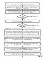
- FIG. 2is a flowchart of connectivity in the environment of FIG. 1 .
- the method of enrolling subscribers for a network service as defined hereinincludes scanning for an initialization token, as depicted at step 200 , and employing the initialization token to establish a first session and identify an operational token, as shown at step 201 .
- the initialization tokenis an open SSID available to any potential subscriber for establishing the welcome screen 152
- the operational tokenis the traffic SSID for secure wireless access.
- other tokensmay be employed for providing initial general access for welcoming potential subscribers, and subsequently transitioning to a secure access mode once authentication, service selection and configuration are complete.
- the user access equipment 182receives, via the first session 142 , a discovery script 162 for identifying the client device 110 and the components within relay node 131 associated with the initialization token 122 and for transmitting the network identity (i.e. IP addresses) of the identified devices in a discovery response 163 (see FIG. 3 ) for enabling a remote login to the devices within relay node 131 , configuration of those devices and then the establishment by the client device 110 of a second session 146 through the newly configured relay node 131 , as depicted at step 203 .
- a discovery script 162for identifying the client device 110 and the components within relay node 131 associated with the initialization token 122 and for transmitting the network identity (i.e. IP addresses) of the identified devices in a discovery response 163 (see FIG. 3 ) for enabling a remote login to the devices within relay node 131 , configuration of those devices and then the establishment by the client device 110 of a second session 146 through the newly configured relay node 131 , as
- the user device 110employs the initialization token 122 and the discovery script 162 to maintain an appearance of a continuous session 152 , 154 , 156 while the remote login by script 168 is reconfiguring the components of relay node 131 and then disconnecting the user from the established first session 142 and reassigning 144 the user to the second session 146 based on the operational token 124 , as disclosed at step 203 .
- the relay node 131represents an operational switching and access node within a switching fabric of the alternate access network ( 132 and connected nodes).
- a relay noderefers to a combination of two or more radios and a router that alternate access network 132 members install, whether that combination is provided in one package, or as separate components connected by Cat5e cables.
- radio 120acts as a WiFi “station” connected to an upstream access point 134
- radio 182acts a WiFi “access point” for other nodes downstream (like 131 - 1 ) and for the client device 110 .
- the terms access point and stationare WiFi terms, exemplifying operation according to IEEE 802.11 standards.
- the receiving radio 120may simply be referred to as an upstream device and the repeater/access point 182 operates as a downstream or relay device.
- the relay nodewould have to include one WiFi access point or one Ethernet jack, so client device 110 may connect to the relay node.
- the relay node 131(or more specifically the devices 120 , 180 , 182 within it) are configured for the alternate access network, while the client device 110 interacts with the user 108 and provides the appearance of a continuous session even when connection to either the alternate access network 132 or the Internet 130 is lost during the configuration process.
- an initial connection 142is made by various approaches, depending on the starting configuration of the components within the relay node 131 , and the configuration process completes as above.
- the initialization script 164identifies the open SSID 122 or determines if none is available.
- the initialization script 164also presents the screen displays 152 , 154 , 156 that define the predetermined GUI observed by the user during the connection switchover from the open SSID 122 to the traffic SSID 124 .
- the discovery script 162which may accompany the initialization script 164 as a combined startup script 165 , sends the identity (IP address) of the user device 110 and of the components within relay node 131 .
- the response to the discovery scriptis the probe application 166 that examines the configuration of the user device 110 and any intervening nodes, contained in the probe response 163 .
- the configuration application 168then performs a login to the alternate access node 131 including the router 180 , receiving radio 120 and repeater radio/access point 182 based on the previously gathered addresses to configure the alternate access network and enable the switchover to the traffic SSID 124 via the local provider network 132 (the alternate access network).
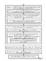
- FIG. 3is an example of configuration in the environment of FIG. 1 .
- the radio 120connects because it found the alternate access open (unencrypted) SSID 122 .
- most nodes in the alternate access networkadvertise 1001 an open public SSID for attracting new subscribers. This open SSID 124 does not give access to the whole Internet but rather redirects users to one or more pages 152 that advertise alternate access services, support alternate access enrollment and allow connections to the alternate access installation server 150 .
- the installation server 150catalogs the equipment's 131 initial startup behavior via a startup, or initialization script 164 , specifically including which URLs it seeks to connect to.
- the web requestis redirected to the alternate access installation server 150 , as shown by arrow 1002 .
- Part of installation server's 150 responseis a discovery script 162 that causes the client device 110 to do a traceroute and report the results to the installation server 150 .
- the sent discovery script 162 ′provides the installation server 150 with the IP addresses 163 of the newly connected equipment 131 , i.e. the IP addresses of the client and of those devices between the client and the known alternate access network elements 134 .
- a server-based application 166 in the installation server 150can then probe 166 ′ these IP addresses for testing factory default login sequences for each of the different devices supported by the alternate access network in order to identify the device. While this is happening, the discovery script 162 ′ displays the welcome page 152 describing the alternate access network, describing what it means to join (i.e. terms and conditions) and offering one or more service plans.
- the installation server 150updates the displayed welcome page 152 to inquire if the user 108 wants to subscribe to the alternate access by clicking on one of the “join” buttons 153 now displayed next to each of the plans. Making this one click sends and invokes the initialization script 164 on the client 110 causes the client to display an hourglass and to poll the alternate access URL every second or so waiting for an installation completion message. It also invokes a configuration process 168 on the installation server 150 which remotely logs into 168 ′ the device or devices that make up the new node 131 , verifies they have the latest software, downloads new software if they do not, and then reconfigures them to be secure elements of the alternate access network 132 .
- the new relay node 131will briefly lose connectivity but will eventually associate with a new secure alternate access SSID 124 and become part of the alternate access network 132 .
- the browser on the subscriber device 110is able to once again connect to installation server 150 which returns the installation complete page 156 .
- the local initialization script 164 ′keeps a local configuration page 154 alive (including a spinning hourglass or more detailed status updates) while the devices within relay node 131 are reconfigured and network connectivity via SSID 122 is temporarily lost for transitioning to the traffic SSID 124 , as shown by arrow 144 .
- the application 168updates the firmware to a latest release for the devices within node 131 as determined by the discovery response 163 , and then configures the devices ( 120 , 180 & 182 ) so the node becomes an alternate access node 131 in the alternate access network 132 .
- Such reconfigurationis performed as part of confirming compatibility and maintaining the appearance of a continuous session for reprogramming and reconfiguring the user's newly installed equipment so it can include a repeater radio 182 to further extend the alternate access network 132 -N.
- the configuration application 168reestablishes a new connection 146 using the traffic SSID 124 , such that upon completion of the configuration application 168 , the new user device 110 is securely connected to the Internet as a node of the alternate access network 132 .
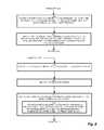
- FIG. 4is an example of configuration as in FIG. 3 but using any other available Internet connection to reach the alternate access network's ISP's website and installation server 150 .
- startup logic 160 for automatically identifying an available SSID 122 and local provider 143is not included in the components that will form relay node 131 .
- relay node 131as shipped by its manufacturer, can relay web connections, but does not have the startup logic 160 and hence, connects to the Internet by some means other than the alternate access network, an extra step is required.
- the user wanting to joinwill have to explicitly type in the URL 155 for direct access to a website including a configuration screen, as shown by arrow 1010 . Once there, the process is as in FIG.
- the radio 182can't identify with certainty whether the new node is just the second address in the traceroute or has several addresses.
- the discovery script 162performs a traceroute to probe the 2nd and subsequent addresses to automatically identify the new node equipment and the IP addresses (if there are several) associated with it.
- a configuration with generic or off-the-shelf equipment not shipped with the startup logic 160requires the user to reach the configuration website, after which one-click configuration as above is all that is required.
- FIG. 5is an example of configuration as in FIG. 3 using manual configuration for the initial connection to the website of the alternative access network.
- a proactive procedureallows the user to initiate the configuration and sign on by establishing an Internet connection through any available gateway 136 .
- a potential network participantobtains an Internet connection, connects their user device 110 or other browsing device, goes to the alternate access installation webpage 152 and downloads a manual configuration application 169 .
- this exchangeis automated by the welcome 152 and configuration screens 154 such that it appears to be just simple web browsing, rather than tearing down and establishing new connections.
- An initial user exchangeoccurs via the user device 110 and the gateway 136 , for receiving the manual configuration application 169 .
- the manual configuration application 169modifies the user device 110 Internet access default to switch over to either a wireless or wired connection to the local access point 182 .
- the manual configuration application 169allows the user to appear to remain connected to the installation server 150 even when they are not connected to the web.
- the manual configuration application 169employs the user device 110 native Wifi API to programmatically change the Wi-Fi access point with which the user web browser device 110 associates.
- the initial connection 142occurs by user initiation of accessing the website 150 , and concludes with a wired or wireless connection to the relay node 131 for wireless communication with the alternate access device 134 .
- the serverdelivers a page offering a list of alternate access compatible devices and asking the user to click on the one they've installed.
- appropriate materialweb pages, configuration images and the configuration applet
- the configuration appletexecutes probe 166 on user device 110 and, if the probed devices appear compatible, then the user sees the welcome page 152 describing alternate access, describing what it means to join and offering one or more plans. As before, the user joins by clicking one of the “join” buttons displayed next to the plans.
- the probing and configuration appletsuse the Native Wifi API to replace the current Wi-Fi association with a new one based on the installed node's default SSID.
- the newly installed node 131is probed and confirmed to be useable. If there is a problem here or at any point in the configuration process, the manual configuration application 169 reconnects to the original Wi-Fi access point 136 and returns an error indication to the alternate access installation server so the alternate access server can lead the user through corrective measures.
- the equipment 131will end up securely associated with the alternate access network 132 , the browser 110 reconnects to the installation server 150 over the local provider 132 network and then displays the installation complete page 156 .
- the browsing device 110If the newly installed node is one to which the user will eventually connect via a fixed Ethernet connection, then it is possible for the browsing device 110 to be simultaneously connected to the Internet (via Wi-Fi) and to the newly installed wireless node (via an Ethernet cable).
- the downloaded configuration application 169is responsible for updating the local routing table on the browsing device 110 after the user is prompted to plug in the Ethernet cable. This is necessary on many devices as some operating systems (e.g. MICROSOFT WINDOWS®) automatically update the default route to the Internet 130 to give priority to physical Ethernet over Wi-Fi while we need to keep default Internet access going via Wi-Fi and only use the physical Ethernet for access to the new device (at least until configuration is complete).
- some operating systemse.g. MICROSOFT WINDOWS®
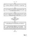
- FIGS. 6-9are a flowchart of configuration as in FIGS. 3-5 .
- the method of enrolling subscribers for the alternate access network serviceincludes, at step 300 , identifying an available SSID 122 for wireless connection, and associating the user device 110 with a remote server 150 to initiate a session 142 based on the identified SSID 122 , as shown at step 301 .
- the initialization script 164determines, based on the scanning, if the initialization token 122 is available for establishing the first session, and if not, receives the URL for the remote server 150 from a user interface 155 , as disclosed at step 302 .
- a checkis performed, at step 303 , to determine if the open SSID is available via preconfigured startup logic 160 , and if so, control passes to step 304 for the registration sequence of FIG. 3 . Otherwise, control passes to step 306 for considering the registration sequence of FIG. 4 .
- a checkis performed to determine if a URL (Uniform Resource Locator) associated with the remote server for establishing the first session can be entered by the user. If the user entered URL can access the installation server 150 for establishing the initialization connection 142 , control passes to step 308 for pursuing the installation sequence of FIG. 4 , otherwise the installation sequence of FIG. 5 is pursued at step 318 .
- a URLUniform Resource Locator
- the access device 182invokes the startup logic 160 for identifying the initialization token 122 , in which, in the example arrangement shown, the initialization token is an SSID for wireless communication according to an established protocol.
- the initialization tokenis an SSID for wireless communication according to an established protocol.
- relay node 131identifies, via the SSID, a predetermined URL for receiving the discovery script 162 , such that the discovery script further includes the initialization script 164 for providing a continuous display of preloaded screens 152 , 154 , 156 .
- the user device 110receives, via the initiated session 122 , the discovery script 162 for identifying at least one network identifier corresponding to the associated user device 110 .
- the identifieris typically expected to be an IP address, but could be any suitable identifier such as a MAC address, for example.
- the user device 110Upon execution, the user device 110 gathers, based on the initialization script 164 , network identifiers of the user device 110 and corresponding devices for receiving the network service 132 , such that the corresponding devices including intervening devices between user device and remote server employed in providing the network services from the remote server 150 , as depicted at step 320 .
- the user device 110reports, via the discovery script 162 , the network identifiers corresponding to the association between the user device 110 and the remote server 150 , as disclosed at step 321 .
- the remote server 150probes each of the devices 110 corresponding to the reported network identifiers to determine if the corresponding devices are compatible with the remote server 150 by executing the probe application 166 for sending probes 166 ′, as shown at step 322 .
- the remote server 150receives a confirmation 163 to the probes 166 ′ to affiliate the associated user device 110 with the network service 132 provided by the remote server 150 , as depicted at step 323 .
- the user device 110receives, via the initiated session 142 , a login sequence for login into the user device 110 , and for establishing an operational session 144 to supercede the initiated session 142 , as depicted at step 324 .
- the user device 110accepts the login from the remote server 150 for configuring, using the configuration application 168 , the identified node 110 for receiving the network service via the second session 144 , as disclosed at step 326 , and confirming, via remote login to the identified nodes (i.e. user device 110 ), compatibility with the remote server 150 providing the network service, as depicted at step 327 .
- the user display of the user device 110presents, based on the discovery script 162 , an interface 152 for receiving a selection 153 to invoke the network service 132 , as shown at step 328 .
- the configuration application 168after logging in, updates the firmware to a latest release for the discovered devices that comprise relay node 131 , as well as any other devices determined by the discovery response 163 , and then configures the devices (e.g.
- the nodebecomes an alternate access node 131 in the alternate access network 132 .
- the configuration application 168reconfigures and establishes the operational session 146
- the user device 110continues executing, during the establishment of the operational session, the initialization script 164 for maintaining the appearance of the continuous session 152 , 154 , 156 on the user device 110 while the initiated session 142 is disconnected and the operational SSID 124 is invoked for association to the remote server 150 , as clarified at step 330 .
- the second session 144is an operational session based on an authenticated SSID 124 , such that the operational session is a secure session, as shown at step 331 .
- the user device 110disconnects from the first session 142 such that connectivity is temporarily lost, as depicted at step 332 , and the configuration application 168 reconfigures the connective device 182 using the identity of the identified elements as intervening nodes, as disclosed at step 333 .
- the user devicethen reestablishing connectivity using the second token 124 for providing the user with controlled access to the alternate access network 132 , as depicted at step 334 .
- performing initial startup behaviorincludes connecting to a predetermined URL 155 for receiving the discovery script, as depicted at step 308 and shown in the configuration example of FIG. 4 .
- the user device 110invokes the discovery script 162 , as depicted at step 309 , and performs a traceroute, or probe 166 ′, for identifying a network address of the newly connected equipment 110 , as disclosed at step 310 .
- the tracerouteincludes sending a series of traceroute messages with an increasing time to live for identifying network elements connected between the newly connected equipment and the predetermined URL, as clarified at step 311 , and control returns to step 318 for configuration as above.
- the sign-on sequenceincludes, in response to scanning for the initialization token, receiving a set of available initialization tokens visible to the user device, as shown at step 312 . These are generally available WiFi signals propagated by devices within range.
- the user 108selects, from a list of the available initialization tokens, an initialization token corresponding to the newly added device for receiving the network service, as depicted at step 313 .
- it can be expected that the userwould be able to identify a signal emanating from the newly connected access device 182 from observing either the name or signal strength and by knowing preexisting signals in proximity.
- the configuration application 168replaces a current wireless access point employed by the user device with the identity of the newly added device 182 for providing wireless access to the user device 110 , as depicted at step 314 .
- the userfurther establishing a physical connection between the user device 110 and the newly added device 182 for receiving the network service, as depicted at step 316 . Since some operating systems route Internet packets over wired interfaces by default, an extra step overrides this preferential treatment for wired external connections allowing simultaneous access to the node 131 devices via the newly connected cable and Internet access via the existing wireless access point, as depicted at step 317 . Control then passes to step 318 to continue configuration as above.
- the programs and methods for seamless access to an alternate access medium as defined hereinare deliverable to a user processing and rendering device in many forms, including but not limited to a) information permanently stored on non-writeable storage media such as ROM devices, b) information alterably stored on writeable non-transitory storage media such as floppy disks, magnetic tapes, CDs, RAM devices, and other magnetic and optical media, or c) information conveyed to a computer through communication media, as in an electronic network such as the Internet or telephone modem lines.
- the operations and methodsmay be implemented in a software executable object or as a set of encoded instructions for execution by a processor responsive to the instructions.
- ASICsApplication Specific Integrated Circuits
- FPGAsField Programmable Gate Arrays
- state machinescontrollers or other hardware components or devices, or a combination of hardware, software, and firmware components.
Landscapes
- Engineering & Computer Science (AREA)
- Computer Networks & Wireless Communication (AREA)
- Signal Processing (AREA)
- Mobile Radio Communication Systems (AREA)
Abstract
Description
Claims (23)
Priority Applications (1)
| Application Number | Priority Date | Filing Date | Title |
|---|---|---|---|
| US13/252,715US8667148B1 (en) | 2010-10-04 | 2011-10-04 | Minimal effort network subscriber registration |
Applications Claiming Priority (2)
| Application Number | Priority Date | Filing Date | Title |
|---|---|---|---|
| US40444910P | 2010-10-04 | 2010-10-04 | |
| US13/252,715US8667148B1 (en) | 2010-10-04 | 2011-10-04 | Minimal effort network subscriber registration |
Publications (1)
| Publication Number | Publication Date |
|---|---|
| US8667148B1true US8667148B1 (en) | 2014-03-04 |
Family
ID=50158902
Family Applications (1)
| Application Number | Title | Priority Date | Filing Date |
|---|---|---|---|
| US13/252,715Active - Reinstated2031-12-18US8667148B1 (en) | 2010-10-04 | 2011-10-04 | Minimal effort network subscriber registration |
Country Status (1)
| Country | Link |
|---|---|
| US (1) | US8667148B1 (en) |
Cited By (14)
| Publication number | Priority date | Publication date | Assignee | Title |
|---|---|---|---|---|
| US20130246397A1 (en)* | 2012-03-19 | 2013-09-19 | Brandon Farver | System and Method for Mode-Based Social Networking |
| US20130347073A1 (en)* | 2012-06-22 | 2013-12-26 | Ellison W. Bryksa | Authorizing secured wireless access at hotspot having open wireless network and secure wireless network |
| US20160105484A1 (en)* | 2014-10-08 | 2016-04-14 | Oce Printing Systems Gmbh & Co. Kg | Method to operate a control panel for a production system, as well as a control system for a production system |
| US9485307B1 (en)* | 2013-09-25 | 2016-11-01 | Imdb.Com, Inc. | Broadcasting network identifiers that are based on media items |
| US9565185B2 (en) | 2014-11-24 | 2017-02-07 | At&T Intellectual Property I, L.P. | Facilitation of seamless security data transfer for wireless network devices |
| US20190208660A1 (en)* | 2016-05-19 | 2019-07-04 | Cimcon Lighting, Inc. | Configurable Data Center Platform |
| US11057774B1 (en) | 2020-05-14 | 2021-07-06 | T-Mobile Usa, Inc. | Intelligent GNODEB cybersecurity protection system |
| US11070982B1 (en) | 2020-04-15 | 2021-07-20 | T-Mobile Usa, Inc. | Self-cleaning function for a network access node of a network |
| US11115824B1 (en) | 2020-05-14 | 2021-09-07 | T-Mobile Usa, Inc. | 5G cybersecurity protection system |
| US11201907B1 (en)* | 2008-09-10 | 2021-12-14 | United Services Automobile Association (Usaa) | Access control center auto launch |
| US11206542B2 (en) | 2020-05-14 | 2021-12-21 | T-Mobile Usa, Inc. | 5G cybersecurity protection system using personalized signatures |
| US11444980B2 (en) | 2020-04-15 | 2022-09-13 | T-Mobile Usa, Inc. | On-demand wireless device centric security for a 5G wireless network |
| US11799878B2 (en) | 2020-04-15 | 2023-10-24 | T-Mobile Usa, Inc. | On-demand software-defined security service orchestration for a 5G wireless network |
| US11824881B2 (en) | 2020-04-15 | 2023-11-21 | T-Mobile Usa, Inc. | On-demand security layer for a 5G wireless network |
Citations (55)
| Publication number | Priority date | Publication date | Assignee | Title |
|---|---|---|---|---|
| US20030115339A1 (en)* | 2001-10-29 | 2003-06-19 | Takeshi Hodoshima | Parameter setting system |
| US20030212802A1 (en)* | 2002-05-09 | 2003-11-13 | Gateway, Inc. | Proximity network encryption and setup |
| US20040054774A1 (en)* | 2002-05-04 | 2004-03-18 | Instant802 Networks Inc. | Using wireless network access points for monitoring radio spectrum traffic and interference |
| US20040133689A1 (en)* | 2002-12-24 | 2004-07-08 | Samrat Vasisht | Method, system and device for automatically configuring a communications network |
| US7089313B2 (en)* | 2002-07-25 | 2006-08-08 | Matsushita Electric Industrial Co., Ltd. | Protocol independent communication system for mobile devices |
| US7184435B2 (en)* | 2002-04-19 | 2007-02-27 | Ju-Fang Hsiao | Method for setting wireless network devices |
| US20070094356A1 (en)* | 2005-10-25 | 2007-04-26 | Aseem Sethi | System and method for context aware profiling for wireless networks |
| US7263076B1 (en)* | 2004-10-09 | 2007-08-28 | Radiuz Networks Llc | System and method for managing a wireless network community |
| US20080019367A1 (en)* | 2004-06-30 | 2008-01-24 | Satoshi Ito | Communication Device, Communication Setting Method, Communication Setting Program And Recording Medium On Which Is Recorded A Communication Setting Program |
| US7333464B2 (en)* | 2006-02-01 | 2008-02-19 | Microsoft Corporation | Automated service discovery and wireless network set-up |
| US7412542B1 (en)* | 2003-11-26 | 2008-08-12 | Microsoft Corporation | Bridging a gaming console with a wireless network |
| US7567805B2 (en)* | 2005-08-01 | 2009-07-28 | Cisco Technology, Inc. | Method and system for dynamic assignment of wireless LAN access point identity |
| US7594021B2 (en)* | 2003-04-11 | 2009-09-22 | Sony Corporation | Radio communication system, radio communication apparatus and method, and program |
| US7613142B2 (en)* | 2002-10-03 | 2009-11-03 | Cisco Technology, Inc. | Method for a wireless station to determine network metrics prior to associating with an access point of a wireless network |
| US7617317B2 (en)* | 2001-12-03 | 2009-11-10 | Sprint Spectrum L.P. | Method and system for allowing multiple service providers to serve users via a common access network |
| US20090327713A1 (en)* | 2005-11-16 | 2009-12-31 | Nokia Corporation | System and method for establishing bearer-independent and secure connections |
| US7653379B1 (en)* | 2002-10-31 | 2010-01-26 | Aol Llc | Configuring wireless devices |
| US7657637B2 (en)* | 2006-05-29 | 2010-02-02 | Funai Electric Co., Ltd. | Client server system for transmitting regular connection information via wireless network to client based on temporary connection information received from wired network |
| US7685295B2 (en)* | 2002-12-19 | 2010-03-23 | Chantry Networks Inc. | Wireless local area communication network system and method |
| US7697932B2 (en)* | 2005-10-17 | 2010-04-13 | Canon Kabushiki Kaisha | Method for efficiently setting communication parameters via real time indexing and selection of algorithm for setting the parameters |
| US20100106966A1 (en)* | 2007-02-07 | 2010-04-29 | 0856972 B.C. Ltd. | Method and System for Registering and Verifying the Identity of Wireless Networks and Devices |
| US20100115108A1 (en)* | 2008-06-11 | 2010-05-06 | Asustek Computer Inc. | Wireless device and method for automatically establishing wireless connection |
| US20100146129A1 (en)* | 2007-05-10 | 2010-06-10 | Canon Kabushiki Kaisha | Communication apparatus and method for wi-fi protected setup in adhoc network |
| US7769837B2 (en)* | 2003-12-12 | 2010-08-03 | Brother Kogyo Kabushiki Kaisha | Wireless LAN setting system and communication terminal |
| US20100214955A1 (en)* | 2007-10-18 | 2010-08-26 | TELEFONAKTIEHOLAGET I M ERICSSON (publ) | Methods and Arrangements in a Mobile Telecommunications Network |
| US20100246416A1 (en)* | 2009-03-25 | 2010-09-30 | Amit Sinha | Systems and methods for remote testing of wireless lan access points |
| US20100263022A1 (en)* | 2008-10-13 | 2010-10-14 | Devicescape Software, Inc. | Systems and Methods for Enhanced Smartclient Support |
| US20100296441A1 (en)* | 2006-02-22 | 2010-11-25 | Elad Barkan | Wireless internet system and method |
| US20100312895A1 (en)* | 2008-02-22 | 2010-12-09 | Canon Kabushiki Kaisha | Communication apparatus, communication method thereof, program and storage medium |
| US7860978B2 (en)* | 2004-01-22 | 2010-12-28 | Toshiba America Research, Inc. | Establishing a secure tunnel to access router |
| US20110029680A1 (en)* | 2008-04-04 | 2011-02-03 | Canon Kabushiki Kaisha | Communication apparatus, and communication method therefor |
| US20110055409A1 (en)* | 2009-08-27 | 2011-03-03 | Arcadyan Technology Corp. | Method For Network Connection |
| US7912465B2 (en)* | 2005-03-24 | 2011-03-22 | Research In Motion Limited | Scanning for wireless local area networks |
| US7925765B2 (en)* | 2006-04-07 | 2011-04-12 | Microsoft Corporation | Cooperative diagnosis in a wireless LAN |
| US7958211B2 (en)* | 2007-10-22 | 2011-06-07 | Sony Corporation | Automatic configuration of wireless device for router |
| US20110145421A1 (en)* | 2009-12-15 | 2011-06-16 | Zongming Yao | Method and apparatus for autonomous peer discovery and enhancing link reliability for wireless peer direct links |
| US7986940B2 (en)* | 2007-07-05 | 2011-07-26 | Azurewave Technologies, Inc. | Automatic wireless network linking method with security configuration and device thereof |
| US8019082B1 (en)* | 2003-06-05 | 2011-09-13 | Mcafee, Inc. | Methods and systems for automated configuration of 802.1x clients |
| US8019879B2 (en)* | 2003-11-07 | 2011-09-13 | Hewlett-Packard Development Company, L.P. | Wireless communications systems and wireless communications methods |
| US20110252152A1 (en)* | 2010-04-09 | 2011-10-13 | Marcus Sherry | Reliable messaging system and method |
| US20110264772A1 (en)* | 2010-04-23 | 2011-10-27 | Hugo Krapf | Method and system for proximity-based, peer-initiated device configuration |
| US8060620B2 (en)* | 2006-10-05 | 2011-11-15 | Microsoft Corporation | Profile deployment using a generic format |
| US20110289229A1 (en)* | 2010-05-05 | 2011-11-24 | BridgeCo Inc. | Methods and systems for wi-fi setup and configuration |
| US20110299463A1 (en)* | 2008-12-23 | 2011-12-08 | Jens Bachmann | Optimized home link detection |
| US8095664B2 (en)* | 2002-09-06 | 2012-01-10 | Sony Corporation | Method, apparatus, and computer program for processing information |
| US8103003B2 (en)* | 2005-06-13 | 2012-01-24 | Canon Kabushiki Kaisha | Method for setting communication parameters and communication device |
| US20120054338A1 (en)* | 2010-08-31 | 2012-03-01 | Brother Kogyo Kabushiki Kaisha | Assistance device |
| US8131859B2 (en)* | 2003-04-23 | 2012-03-06 | Canon Kabushiki Kaisha | Wireless communication system, and wireless communication device and control method |
| US20120079123A1 (en)* | 2010-09-27 | 2012-03-29 | Research In Motion Limited | Method, system and apparatus for enabling access of a first mobile electronic device to at least one network accessible by a second mobile electronic device |
| US8150980B2 (en)* | 2007-08-01 | 2012-04-03 | Canon Kabushiki Kaisha | Communication apparatus and method thereof that determine communication partner for performing automatic setting process of communication parameter |
| US8161170B2 (en)* | 2005-05-30 | 2012-04-17 | Canon Kabushiki Kaisha | System having electronic device with multiple interfaces and host apparatus, information processing device, electronic device, and setup method, control method and program therefor |
| US8238238B2 (en)* | 2008-05-16 | 2012-08-07 | Microsoft Corporation | Performing networking tasks based on destination networks |
| US8259650B2 (en)* | 2007-09-14 | 2012-09-04 | Sony Corporation | Communication device connectable to an access point based on setting information wirelessly provided from another device, a system having such communication device, and a method utilizing such communication device |
| US8352616B2 (en)* | 2009-05-19 | 2013-01-08 | Cisco Technology, Inc. | Configuring a network connection |
| US8526352B2 (en)* | 2009-06-30 | 2013-09-03 | France Telecom | Method of controlling an entity of a remote network from a local network |
- 2011
- 2011-10-04USUS13/252,715patent/US8667148B1/enactiveActive - Reinstated
Patent Citations (57)
| Publication number | Priority date | Publication date | Assignee | Title |
|---|---|---|---|---|
| US20030115339A1 (en)* | 2001-10-29 | 2003-06-19 | Takeshi Hodoshima | Parameter setting system |
| US7617317B2 (en)* | 2001-12-03 | 2009-11-10 | Sprint Spectrum L.P. | Method and system for allowing multiple service providers to serve users via a common access network |
| US7184435B2 (en)* | 2002-04-19 | 2007-02-27 | Ju-Fang Hsiao | Method for setting wireless network devices |
| US20040054774A1 (en)* | 2002-05-04 | 2004-03-18 | Instant802 Networks Inc. | Using wireless network access points for monitoring radio spectrum traffic and interference |
| US20050073979A1 (en)* | 2002-05-04 | 2005-04-07 | Instant802 Networks, Inc. | Visitor gateway in a wireless network |
| US7382756B2 (en)* | 2002-05-04 | 2008-06-03 | Broadcom Corporation | Integrated user and radio management in a wireless network environment |
| US20030212802A1 (en)* | 2002-05-09 | 2003-11-13 | Gateway, Inc. | Proximity network encryption and setup |
| US7089313B2 (en)* | 2002-07-25 | 2006-08-08 | Matsushita Electric Industrial Co., Ltd. | Protocol independent communication system for mobile devices |
| US8095664B2 (en)* | 2002-09-06 | 2012-01-10 | Sony Corporation | Method, apparatus, and computer program for processing information |
| US7613142B2 (en)* | 2002-10-03 | 2009-11-03 | Cisco Technology, Inc. | Method for a wireless station to determine network metrics prior to associating with an access point of a wireless network |
| US7653379B1 (en)* | 2002-10-31 | 2010-01-26 | Aol Llc | Configuring wireless devices |
| US7685295B2 (en)* | 2002-12-19 | 2010-03-23 | Chantry Networks Inc. | Wireless local area communication network system and method |
| US20040133689A1 (en)* | 2002-12-24 | 2004-07-08 | Samrat Vasisht | Method, system and device for automatically configuring a communications network |
| US7594021B2 (en)* | 2003-04-11 | 2009-09-22 | Sony Corporation | Radio communication system, radio communication apparatus and method, and program |
| US8131859B2 (en)* | 2003-04-23 | 2012-03-06 | Canon Kabushiki Kaisha | Wireless communication system, and wireless communication device and control method |
| US8019082B1 (en)* | 2003-06-05 | 2011-09-13 | Mcafee, Inc. | Methods and systems for automated configuration of 802.1x clients |
| US8019879B2 (en)* | 2003-11-07 | 2011-09-13 | Hewlett-Packard Development Company, L.P. | Wireless communications systems and wireless communications methods |
| US7412542B1 (en)* | 2003-11-26 | 2008-08-12 | Microsoft Corporation | Bridging a gaming console with a wireless network |
| US7769837B2 (en)* | 2003-12-12 | 2010-08-03 | Brother Kogyo Kabushiki Kaisha | Wireless LAN setting system and communication terminal |
| US7860978B2 (en)* | 2004-01-22 | 2010-12-28 | Toshiba America Research, Inc. | Establishing a secure tunnel to access router |
| US20080019367A1 (en)* | 2004-06-30 | 2008-01-24 | Satoshi Ito | Communication Device, Communication Setting Method, Communication Setting Program And Recording Medium On Which Is Recorded A Communication Setting Program |
| US7263076B1 (en)* | 2004-10-09 | 2007-08-28 | Radiuz Networks Llc | System and method for managing a wireless network community |
| US7912465B2 (en)* | 2005-03-24 | 2011-03-22 | Research In Motion Limited | Scanning for wireless local area networks |
| US8161170B2 (en)* | 2005-05-30 | 2012-04-17 | Canon Kabushiki Kaisha | System having electronic device with multiple interfaces and host apparatus, information processing device, electronic device, and setup method, control method and program therefor |
| US8103003B2 (en)* | 2005-06-13 | 2012-01-24 | Canon Kabushiki Kaisha | Method for setting communication parameters and communication device |
| US7567805B2 (en)* | 2005-08-01 | 2009-07-28 | Cisco Technology, Inc. | Method and system for dynamic assignment of wireless LAN access point identity |
| US7697932B2 (en)* | 2005-10-17 | 2010-04-13 | Canon Kabushiki Kaisha | Method for efficiently setting communication parameters via real time indexing and selection of algorithm for setting the parameters |
| US20070094356A1 (en)* | 2005-10-25 | 2007-04-26 | Aseem Sethi | System and method for context aware profiling for wireless networks |
| US20090327713A1 (en)* | 2005-11-16 | 2009-12-31 | Nokia Corporation | System and method for establishing bearer-independent and secure connections |
| US7333464B2 (en)* | 2006-02-01 | 2008-02-19 | Microsoft Corporation | Automated service discovery and wireless network set-up |
| US20100296441A1 (en)* | 2006-02-22 | 2010-11-25 | Elad Barkan | Wireless internet system and method |
| US7925765B2 (en)* | 2006-04-07 | 2011-04-12 | Microsoft Corporation | Cooperative diagnosis in a wireless LAN |
| US7657637B2 (en)* | 2006-05-29 | 2010-02-02 | Funai Electric Co., Ltd. | Client server system for transmitting regular connection information via wireless network to client based on temporary connection information received from wired network |
| US8060620B2 (en)* | 2006-10-05 | 2011-11-15 | Microsoft Corporation | Profile deployment using a generic format |
| US20100106966A1 (en)* | 2007-02-07 | 2010-04-29 | 0856972 B.C. Ltd. | Method and System for Registering and Verifying the Identity of Wireless Networks and Devices |
| US20100146129A1 (en)* | 2007-05-10 | 2010-06-10 | Canon Kabushiki Kaisha | Communication apparatus and method for wi-fi protected setup in adhoc network |
| US7986940B2 (en)* | 2007-07-05 | 2011-07-26 | Azurewave Technologies, Inc. | Automatic wireless network linking method with security configuration and device thereof |
| US8150980B2 (en)* | 2007-08-01 | 2012-04-03 | Canon Kabushiki Kaisha | Communication apparatus and method thereof that determine communication partner for performing automatic setting process of communication parameter |
| US8259650B2 (en)* | 2007-09-14 | 2012-09-04 | Sony Corporation | Communication device connectable to an access point based on setting information wirelessly provided from another device, a system having such communication device, and a method utilizing such communication device |
| US20100214955A1 (en)* | 2007-10-18 | 2010-08-26 | TELEFONAKTIEHOLAGET I M ERICSSON (publ) | Methods and Arrangements in a Mobile Telecommunications Network |
| US7958211B2 (en)* | 2007-10-22 | 2011-06-07 | Sony Corporation | Automatic configuration of wireless device for router |
| US20100312895A1 (en)* | 2008-02-22 | 2010-12-09 | Canon Kabushiki Kaisha | Communication apparatus, communication method thereof, program and storage medium |
| US20110029680A1 (en)* | 2008-04-04 | 2011-02-03 | Canon Kabushiki Kaisha | Communication apparatus, and communication method therefor |
| US8238238B2 (en)* | 2008-05-16 | 2012-08-07 | Microsoft Corporation | Performing networking tasks based on destination networks |
| US20100115108A1 (en)* | 2008-06-11 | 2010-05-06 | Asustek Computer Inc. | Wireless device and method for automatically establishing wireless connection |
| US20100263022A1 (en)* | 2008-10-13 | 2010-10-14 | Devicescape Software, Inc. | Systems and Methods for Enhanced Smartclient Support |
| US20110299463A1 (en)* | 2008-12-23 | 2011-12-08 | Jens Bachmann | Optimized home link detection |
| US20100246416A1 (en)* | 2009-03-25 | 2010-09-30 | Amit Sinha | Systems and methods for remote testing of wireless lan access points |
| US8352616B2 (en)* | 2009-05-19 | 2013-01-08 | Cisco Technology, Inc. | Configuring a network connection |
| US8526352B2 (en)* | 2009-06-30 | 2013-09-03 | France Telecom | Method of controlling an entity of a remote network from a local network |
| US20110055409A1 (en)* | 2009-08-27 | 2011-03-03 | Arcadyan Technology Corp. | Method For Network Connection |
| US20110145421A1 (en)* | 2009-12-15 | 2011-06-16 | Zongming Yao | Method and apparatus for autonomous peer discovery and enhancing link reliability for wireless peer direct links |
| US20110252152A1 (en)* | 2010-04-09 | 2011-10-13 | Marcus Sherry | Reliable messaging system and method |
| US20110264772A1 (en)* | 2010-04-23 | 2011-10-27 | Hugo Krapf | Method and system for proximity-based, peer-initiated device configuration |
| US20110289229A1 (en)* | 2010-05-05 | 2011-11-24 | BridgeCo Inc. | Methods and systems for wi-fi setup and configuration |
| US20120054338A1 (en)* | 2010-08-31 | 2012-03-01 | Brother Kogyo Kabushiki Kaisha | Assistance device |
| US20120079123A1 (en)* | 2010-09-27 | 2012-03-29 | Research In Motion Limited | Method, system and apparatus for enabling access of a first mobile electronic device to at least one network accessible by a second mobile electronic device |
Non-Patent Citations (2)
| Title |
|---|
| IBM. (Oct. 18, 2007). Ultra Secure Wireless Network Setup Solution. IP.com Prior Art Database Technical Disclosure Bulletin. 6 pp. Retrieved from http://ip.com/IPCOM/000159369.* |
| Microsoft. (Feb. 16, 2007). How to change the binding order of network adapters in Windows XP and in Windows 2000. 8 pp. Retrieved from http://support.microsoft.com/kb/894564.* |
Cited By (28)
| Publication number | Priority date | Publication date | Assignee | Title |
|---|---|---|---|---|
| US11201907B1 (en)* | 2008-09-10 | 2021-12-14 | United Services Automobile Association (Usaa) | Access control center auto launch |
| US20130246397A1 (en)* | 2012-03-19 | 2013-09-19 | Brandon Farver | System and Method for Mode-Based Social Networking |
| US9043297B2 (en)* | 2012-03-19 | 2015-05-26 | Brandon Farver | System and method for mode-based social networking |
| US9961548B2 (en) | 2012-06-22 | 2018-05-01 | Guest Tek Interactive Entertainment Ltd. | Authorizing secured wireless access at hotspot according to user-specific access credential received from client device during predetermined sign-up process |
| US20160019475A1 (en)* | 2012-06-22 | 2016-01-21 | Guest Tek Interactive Entertainment Ltd. | Authorizing secured wireless access at hotspot by loading user-specific access credential for user according to identity of the user |
| US9161219B2 (en)* | 2012-06-22 | 2015-10-13 | Guest Tek Interactive Entertainment Ltd. | Authorizing secured wireless access at hotspot having open wireless network and secure wireless network |
| US9615252B2 (en)* | 2012-06-22 | 2017-04-04 | Guest Tek Interactive Entertainment Ltd. | Re-login time duration allowing hotspot user to sign up for additional access time without disconnecting from secured wireless network |
| US20130347073A1 (en)* | 2012-06-22 | 2013-12-26 | Ellison W. Bryksa | Authorizing secured wireless access at hotspot having open wireless network and secure wireless network |
| US10805797B2 (en) | 2012-06-22 | 2020-10-13 | Guest Tek Interactive Entertainment Ltd. | Enabling secured wireless access using user-specific access credential for secure SSID |
| US10299126B2 (en) | 2012-06-22 | 2019-05-21 | Guest Tek Interactive Entertainment Ltd. | Enabling secured wireless access at hotspot by providing user-specific access credential for secure SSID during sign-up process conducted over open wireless network |
| US9485307B1 (en)* | 2013-09-25 | 2016-11-01 | Imdb.Com, Inc. | Broadcasting network identifiers that are based on media items |
| US10027750B1 (en) | 2013-09-25 | 2018-07-17 | Imdb.Com, Inc. | Utilizing network identifiers that are based on media items |
| US20160105484A1 (en)* | 2014-10-08 | 2016-04-14 | Oce Printing Systems Gmbh & Co. Kg | Method to operate a control panel for a production system, as well as a control system for a production system |
| US10616766B2 (en) | 2014-11-24 | 2020-04-07 | At&T Intellectual Property I, L.P. | Facilitation of seamless security data transfer for wireless network devices |
| US10070312B2 (en) | 2014-11-24 | 2018-09-04 | At&T Intellectual Property I, L.P. | Facilitation of seamless security data transfer for wireless network devices |
| US9565185B2 (en) | 2014-11-24 | 2017-02-07 | At&T Intellectual Property I, L.P. | Facilitation of seamless security data transfer for wireless network devices |
| US11606876B2 (en)* | 2016-05-19 | 2023-03-14 | Cimcon Lighting, Inc. | Configurable data center platform |
| US20190208660A1 (en)* | 2016-05-19 | 2019-07-04 | Cimcon Lighting, Inc. | Configurable Data Center Platform |
| US11824881B2 (en) | 2020-04-15 | 2023-11-21 | T-Mobile Usa, Inc. | On-demand security layer for a 5G wireless network |
| US11070982B1 (en) | 2020-04-15 | 2021-07-20 | T-Mobile Usa, Inc. | Self-cleaning function for a network access node of a network |
| US11799878B2 (en) | 2020-04-15 | 2023-10-24 | T-Mobile Usa, Inc. | On-demand software-defined security service orchestration for a 5G wireless network |
| US11444980B2 (en) | 2020-04-15 | 2022-09-13 | T-Mobile Usa, Inc. | On-demand wireless device centric security for a 5G wireless network |
| US11533624B2 (en) | 2020-04-15 | 2022-12-20 | T-Mobile Usa, Inc. | On-demand security for network resources or nodes, such as for a wireless 5G network |
| US11206542B2 (en) | 2020-05-14 | 2021-12-21 | T-Mobile Usa, Inc. | 5G cybersecurity protection system using personalized signatures |
| US11558747B2 (en) | 2020-05-14 | 2023-01-17 | T-Mobile Usa, Inc. | Intelligent cybersecurity protection system, such as for use in 5G networks |
| US11659396B2 (en) | 2020-05-14 | 2023-05-23 | T-Mobile Usa, Inc. | Intelligent cybersecurity protection system, such as for use in 5G networks |
| US11115824B1 (en) | 2020-05-14 | 2021-09-07 | T-Mobile Usa, Inc. | 5G cybersecurity protection system |
| US11057774B1 (en) | 2020-05-14 | 2021-07-06 | T-Mobile Usa, Inc. | Intelligent GNODEB cybersecurity protection system |
Similar Documents
| Publication | Publication Date | Title |
|---|---|---|
| US8667148B1 (en) | Minimal effort network subscriber registration | |
| US9912635B2 (en) | Auto provisioning of bulk access points | |
| JP6161076B2 (en) | An extensible framework for wireless network connectivity | |
| US9872202B2 (en) | Ad hoc wireless networking | |
| US8509726B2 (en) | Troubleshooting link and protocol in a wireless network | |
| US8200773B2 (en) | Client-side network access policies and management applications | |
| CN101341710B (en) | Support for integrated WLAN hotspot clients | |
| US8356346B2 (en) | VPN secure sessions with dynamic IP addresses | |
| US20060041931A1 (en) | Service level assurance system and method for wired and wireless broadband networks | |
| US20060168656A1 (en) | UPnP VPN gateway configuration service | |
| US20240196214A1 (en) | Facilitating Residential Wireless Roaming Via VPN Connectivity Over Public Service Provider Networks | |
| US20220114008A1 (en) | Cloud-based managed networking service that enables users to consume managed virtualized network functions at edge locations | |
| CN105794149B (en) | Data network, network controller and method for managing routing device | |
| JP2011515921A (en) | Touchless plug and play base transceiver station | |
| US20110196962A1 (en) | Method for Obtaining Information from a Local Terminal Environment | |
| CN118740846A (en) | Network access server NAS device, system and method | |
| CN105634899A (en) | Method and system for providing virtual network service | |
| US10348566B2 (en) | Automated service delivery based on automated identifier discovery | |
| US12096214B2 (en) | Establishing a backup connectivity between a sensor and a management system | |
| US12289219B2 (en) | System and method for configuring a device through an email/SMS | |
| US20250317359A1 (en) | Synchronization of network orchestration with core service registration procedures | |
| Anderhub et al. | CentriFi: A CentralizedWireless Access Point Management Platform |
Legal Events
| Date | Code | Title | Description |
|---|---|---|---|
| AS | Assignment | Owner name:NETBLAZR INC., MASSACHUSETTS Free format text:ASSIGNMENT OF ASSIGNORS INTEREST;ASSIGNOR:TURNER, R. BROUGH;REEL/FRAME:027222/0116 Effective date:20111104 | |
| STCF | Information on status: patent grant | Free format text:PATENTED CASE | |
| FPAY | Fee payment | Year of fee payment:4 | |
| FEPP | Fee payment procedure | Free format text:MAINTENANCE FEE REMINDER MAILED (ORIGINAL EVENT CODE: REM.); ENTITY STATUS OF PATENT OWNER: SMALL ENTITY | |
| LAPS | Lapse for failure to pay maintenance fees | Free format text:PATENT EXPIRED FOR FAILURE TO PAY MAINTENANCE FEES (ORIGINAL EVENT CODE: EXP.); ENTITY STATUS OF PATENT OWNER: SMALL ENTITY | |
| STCH | Information on status: patent discontinuation | Free format text:PATENT EXPIRED DUE TO NONPAYMENT OF MAINTENANCE FEES UNDER 37 CFR 1.362 | |
| FP | Lapsed due to failure to pay maintenance fee | Effective date:20220304 | |
| PRDP | Patent reinstated due to the acceptance of a late maintenance fee | Effective date:20220518 | |
| FEPP | Fee payment procedure | Free format text:PETITION RELATED TO MAINTENANCE FEES FILED (ORIGINAL EVENT CODE: PMFP); ENTITY STATUS OF PATENT OWNER: SMALL ENTITY Free format text:PETITION RELATED TO MAINTENANCE FEES GRANTED (ORIGINAL EVENT CODE: PMFG); ENTITY STATUS OF PATENT OWNER: SMALL ENTITY Free format text:SURCHARGE, PETITION TO ACCEPT PYMT AFTER EXP, UNINTENTIONAL. (ORIGINAL EVENT CODE: M2558); ENTITY STATUS OF PATENT OWNER: SMALL ENTITY | |
| MAFP | Maintenance fee payment | Free format text:PAYMENT OF MAINTENANCE FEE, 8TH YR, SMALL ENTITY (ORIGINAL EVENT CODE: M2552); ENTITY STATUS OF PATENT OWNER: SMALL ENTITY Year of fee payment:8 | |
| STCF | Information on status: patent grant | Free format text:PATENTED CASE | |
| AS | Assignment | Owner name:CRESTLNE DIRECT FIINANCE, L.P., TEXAS Free format text:SECURITY INTEREST;ASSIGNOR:NETBLAZR INC.;REEL/FRAME:060957/0534 Effective date:20220831 |