US8666512B2 - Implantable medical device lead including inner coil reverse-wound relative to shocking coil - Google Patents
Implantable medical device lead including inner coil reverse-wound relative to shocking coilDownload PDFInfo
- Publication number
- US8666512B2 US8666512B2US13/620,934US201213620934AUS8666512B2US 8666512 B2US8666512 B2US 8666512B2US 201213620934 AUS201213620934 AUS 201213620934AUS 8666512 B2US8666512 B2US 8666512B2
- Authority
- US
- United States
- Prior art keywords
- lead
- medical device
- coil
- defibrillation
- electrode
- Prior art date
- Legal status (The legal status is an assumption and is not a legal conclusion. Google has not performed a legal analysis and makes no representation as to the accuracy of the status listed.)
- Active
Links
- 239000004020conductorSubstances0.000claimsabstractdescription37
- 238000004804windingMethods0.000claimsabstractdescription28
- 238000002595magnetic resonance imagingMethods0.000description12
- BASFCYQUMIYNBI-UHFFFAOYSA-NplatinumChemical compound[Pt]BASFCYQUMIYNBI-UHFFFAOYSA-N0.000description9
- 210000001519tissueAnatomy0.000description8
- 230000000747cardiac effectEffects0.000description4
- 230000008878couplingEffects0.000description4
- 238000010168coupling processMethods0.000description4
- 238000005859coupling reactionMethods0.000description4
- 229920000840ethylene tetrafluoroethylene copolymerPolymers0.000description4
- 229920000295expanded polytetrafluoroethylenePolymers0.000description4
- 238000012986modificationMethods0.000description4
- 230000004048modificationEffects0.000description4
- 229910052697platinumInorganic materials0.000description4
- 229920001343polytetrafluoroethylenePolymers0.000description4
- 239000004810polytetrafluoroethyleneSubstances0.000description4
- 210000005245right atriumAnatomy0.000description4
- 210000001321subclavian veinAnatomy0.000description4
- 239000010936titaniumSubstances0.000description4
- 230000002792vascularEffects0.000description4
- 210000002620vena cava superiorAnatomy0.000description4
- PXHVJJICTQNCMI-UHFFFAOYSA-NNickelChemical compound[Ni]PXHVJJICTQNCMI-UHFFFAOYSA-N0.000description3
- RTAQQCXQSZGOHL-UHFFFAOYSA-NTitaniumChemical compound[Ti]RTAQQCXQSZGOHL-UHFFFAOYSA-N0.000description3
- 210000003129brachiocephalic veinAnatomy0.000description3
- 238000010438heat treatmentMethods0.000description3
- 230000007246mechanismEffects0.000description3
- 238000000034methodMethods0.000description3
- 230000033764rhythmic processEffects0.000description3
- 210000005241right ventricleAnatomy0.000description3
- 229910052719titaniumInorganic materials0.000description3
- 239000004809TeflonSubstances0.000description2
- 229920006362Teflon®Polymers0.000description2
- 210000002048axillary veinAnatomy0.000description2
- 239000008280bloodSubstances0.000description2
- 210000004369bloodAnatomy0.000description2
- HTXDPTMKBJXEOW-UHFFFAOYSA-NdioxoiridiumChemical compoundO=[Ir]=OHTXDPTMKBJXEOW-UHFFFAOYSA-N0.000description2
- QHSJIZLJUFMIFP-UHFFFAOYSA-Nethene;1,1,2,2-tetrafluoroetheneChemical groupC=C.FC(F)=C(F)FQHSJIZLJUFMIFP-UHFFFAOYSA-N0.000description2
- 238000003384imaging methodMethods0.000description2
- 238000002513implantationMethods0.000description2
- 229910000457iridium oxideInorganic materials0.000description2
- 239000000463materialSubstances0.000description2
- 239000012811non-conductive materialSubstances0.000description2
- 229920001296polysiloxanePolymers0.000description2
- -1polytetrafluoroethylenePolymers0.000description2
- 238000002560therapeutic procedureMethods0.000description2
- 210000003462veinAnatomy0.000description2
- 238000005481NMR spectroscopyMethods0.000description1
- BQCADISMDOOEFD-UHFFFAOYSA-NSilverChemical compound[Ag]BQCADISMDOOEFD-UHFFFAOYSA-N0.000description1
- 210000001015abdomenAnatomy0.000description1
- 238000007792additionMethods0.000description1
- 230000006793arrhythmiaEffects0.000description1
- 206010003119arrhythmiaDiseases0.000description1
- 238000009125cardiac resynchronization therapyMethods0.000description1
- 230000005670electromagnetic radiationEffects0.000description1
- 210000005240left ventricleAnatomy0.000description1
- 210000004165myocardiumAnatomy0.000description1
- 229910052759nickelInorganic materials0.000description1
- JMOHEPRYPIIZQU-UHFFFAOYSA-Noxygen(2-);tantalum(2+)Chemical compound[O-2].[Ta+2]JMOHEPRYPIIZQU-UHFFFAOYSA-N0.000description1
- 238000002633shock therapyMethods0.000description1
- 229910052709silverInorganic materials0.000description1
- 239000004332silverSubstances0.000description1
- 230000004936stimulating effectEffects0.000description1
- 230000000638stimulationEffects0.000description1
- 238000007920subcutaneous administrationMethods0.000description1
- 230000001225therapeutic effectEffects0.000description1
- 210000000591tricuspid valveAnatomy0.000description1
- 210000001631vena cava inferiorAnatomy0.000description1
Images


Classifications
- A—HUMAN NECESSITIES
- A61—MEDICAL OR VETERINARY SCIENCE; HYGIENE
- A61N—ELECTROTHERAPY; MAGNETOTHERAPY; RADIATION THERAPY; ULTRASOUND THERAPY
- A61N1/00—Electrotherapy; Circuits therefor
- A61N1/02—Details
- A61N1/04—Electrodes
- A61N1/05—Electrodes for implantation or insertion into the body, e.g. heart electrode
- A61N1/056—Transvascular endocardial electrode systems
- A61N1/0563—Transvascular endocardial electrode systems specially adapted for defibrillation or cardioversion
- A—HUMAN NECESSITIES
- A61—MEDICAL OR VETERINARY SCIENCE; HYGIENE
- A61N—ELECTROTHERAPY; MAGNETOTHERAPY; RADIATION THERAPY; ULTRASOUND THERAPY
- A61N1/00—Electrotherapy; Circuits therefor
- A61N1/02—Details
- A61N1/08—Arrangements or circuits for monitoring, protecting, controlling or indicating
- A61N1/086—Magnetic resonance imaging [MRI] compatible leads
Definitions
- the present disclosurerelates to implantable medical devices. More particularly, the present disclosure relates to a medical device lead including an inner coil conductor reverse-wound relative to one or more shocking coils.
- Magnetic resonance imagingis a non-invasive imaging procedure that utilizes nuclear magnetic resonance techniques to render images within a patient's body.
- MRI systemsemploy the use of a magnetic coil having a magnetic field strength of between about 0.2 to 3 Teslas (T).
- TMagnetic field strength
- the body tissueis briefly exposed to RF pulses of electromagnetic energy in a plane perpendicular to the magnetic field. The resultant electromagnetic energy from these pulses can be used to image the body tissue by measuring the relaxation properties of the excited atomic nuclei in the tissue.
- the electromagnetic radiation produced by the MRI systemmay be picked up by implantable device leads used in implantable medical devices such as pacemakers or cardiac defibrillators.
- This energymay be transferred through the lead to the electrode in contact with the tissue, which may lead to elevated temperatures at the point of contact.
- the degree of tissue heatingis typically related to factors such as the length of the lead, the conductivity or impedance of the lead, and the surface area of the lead electrodes. Exposure to a magnetic field may also induce an undesired voltage on the lead.
- a medical device leadincluding an inner conductive coil having a first winding direction and a defibrillation coil electrode having a second winding direction opposite the first winding direction, as well as medical device systems including such a lead.
- a medical device leadin Example 1, includes a proximal connector configured to couple the lead to a pulse generator and an insulative lead body extending distally from the proximal connector.
- the leadalso includes an inner conductor and one or more cable conductors coupled to the proximal connector at a proximal end and extending through the lead body.
- the leadfurther includes one or more defibrillation coil electrodes each coupled to a distal end of one of the one or more cable conductors.
- the one or more defibrillation coil electrodesare each disposed around and electrically isolated from the inner conductive coil.
- the one or more defibrillation coil electrodeseach have a first winding direction and the inner conductive coil has a second winding direction opposite the first winding direction.
- Example 2the medical device lead according to Example 1, wherein one or more defibrillation coils are separated from the inner conductor by an insulative layer.
- Example 3the medical device lead according to either Example 1 or 2, wherein the inner conductor is coupled to one or more pace/sense electrodes at a distal end of the inner conductor.
- Example 4the medical device lead according to any of Examples 1-3, wherein the inner conductor comprises one or more coils.
- Example 5the medical device lead according to any of Examples 1-4, wherein at least one of the one or more coils is unifilar.
- a medical device leadin Example 6, includes a first distal electrode, a first inner conductive coil having a distal end electrically coupled to the first distal electrode, a cable conductor, and a defibrillation coil electrode coupled to a distal end of the one or more cable conductors.
- the defibrillation coilis disposed around and electrically isolated from the first inner conductive coil.
- the defibrillation coilhas a first winding direction and the first inner conductive coil has a second winding direction opposite the first winding direction.
- Example 7the medical device lead according to Example 6, wherein one or more defibrillation coils are separated from the first inner conductive coil by an insulative layer.
- Example 8the medical device lead according to either Example 6 or 7, wherein the first inner conductive coil is unifilar.
- Example 9the medical device lead according to any of Examples 6-8, wherein the first distal electrode is a tip electrode.
- Example 10the medical device lead according to any of Examples 6-9, wherein a temperature increase at the first electrode in an MRI environment is less than about 3.0° C.
- Example 11the medical device lead according to any of Examples 6-10, and further comprising a second distal electrode and a second inner conductive coil having a distal end electrically coupled to the second distal electrode, wherein the second inner conductive coil has the second winding direction.
- Example 12the medical device lead according to any of Examples 6-11, wherein the second inner conductive coil is unifilar.
- Example 13the medical device lead according to any of Examples 6-12, wherein the second distal electrode is a ring electrode.
- a medical devicein Example 14, includes a pulse generator and a lead.
- the leadincludes a proximal connector configured to couple the lead to the pulse generator, an insulative lead body extending distally from the proximal connector, and an inner conductive coil assembly and one or more cable conductors coupled to the proximal connector and extending through the lead body.
- the leadalso includes one or more defibrillation coil electrodes each coupled to a distal end of one of the one or more cable conductors.
- the one or more defibrillation coil electrodesare disposed around and electrically isolated from the inner conductive coil.
- the one or more defibrillation coil electrodeshave a first winding direction and the inner conductive coil has a second winding direction opposite the first winding direction.
- Example 15the medical device according to Example 14, wherein the one or more defibrillation coils are separated from the inner conductive coil assembly by an insulative layer.
- Example 16the medical device according to either Example 14 or 15, wherein the inner conductive coil assembly is coupled to one or more pace/sense electrodes at a distal end of the inner conductive coil assembly.
- Example 17the medical device according to any of Examples 14-16, wherein the one or more pace/sense electrodes comprise at least one of a tip electrode and a ring electrode.
- Example 18the medical device according to any of Examples 14-17, wherein a temperature increase at each of the one or more pace/sense electrodes in an MRI environment is less than about 3.0° C.
- Example 19the medical device according to any of Examples 14-18, wherein the inner conductive coil assembly comprises one or more coils.
- Example 20the medical device according to any of Examples 14-19, wherein at least one of the one or more coils is unifilar.
- FIG. 1is a schematic view of a cardiac rhythm management (CRM) system including a pulse generator and a lead implanted in a patient's heart according to an embodiment of the present disclosure.
- CRMcardiac rhythm management
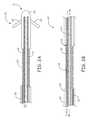
- FIG. 2Ais a schematic view of a distal portion of a lead according to an embodiment of the present disclosure including two defibrillation coils that are reverse-wound with respect to an inner conductive coil.
- FIG. 2Bis a schematic view of a portion of the lead proximal to the distal portion of the lead shown in FIG. 2A .
- FIG. 3is a schematic view of a distal portion of a lead according to another embodiment of the present disclosure including a defibrillation coil that is reverse-wound with respect to inner conductive coils.
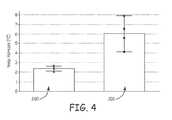
- FIG. 4is a graph comparing measured temperature increase for a lead including an inner conductive coil wound in the opposite direction as the defibrillation coil with a lead including an inner conductive coil wound in the same direction as the defibrillation coil.
- FIG. 1is a schematic view of a cardiac rhythm management (CRM) system 10 according to an embodiment of the present disclosure.
- the CRM system 10includes a pulse generator 12 coupled to a plurality of leads 14 , 16 deployed in a patient's heart 18 .
- the heart 18includes a right atrium 24 and a right ventricle 26 separated by a tricuspid valve 28 .
- deoxygenated bloodis fed into the right atrium 24 through the superior vena cava 30 and the inferior vena cava 32 .
- the major veins supplying blood to the superior vena cava 30include the right and left axillary veins 34 and 36 , which flow into the right and left subclavian veins 38 and 40 .
- the right and left external jugular 42 and 44along with the right and left internal jugular 46 and 48 , join the right and left subclavian veins 38 and 40 to form the right and left brachiocephalic veins 50 and 52 , which in turn combine to flow into the superior vena cava 30 .
- the leads 14 , 16operate to convey electrical signals and stimuli between the pulse generator 12 and the heart 18 .
- the lead 14is implanted in the right ventricle 26
- the lead 16is implanted in the right atrium 24 .
- the CRM system 10may include additional leads, e.g., a lead extending into a coronary vein for stimulating the left ventricle in a bi-ventricular pacing or cardiac resynchronization therapy system.
- the leads 14 , 16enter the vascular system through a vascular entry site 54 formed in the wall of the left subclavian vein 40 , extend through the left brachiocephalic vein 52 and the superior vena cava 30 , and are implanted in the right ventricle 26 and right atrium 24 , respectively.
- the leads 14 , 16may enter the vascular system through the right subclavian vein 38 , the left axillary vein 36 , the left external jugular 44 , the left internal jugular 48 , or the left brachiocephalic vein 52 .
- the pulse generator 12is typically implanted subcutaneously within an implantation location or pocket in the patient's chest or abdomen.
- the pulse generator 12may be an implantable medical device known in the art or later developed, for delivering an electrical therapeutic stimulus to the patient.
- the pulse generator 12is a pacemaker, an implantable cardiac defibrillator, and/or includes both stimulation and defibrillation capabilities.
- the portion of the leads 14 , 16 extending from the pulse generator 12 to the vascular entry site 54are also located subcutaneously or submuscularly.
- the leads 14 , 16are each connected to the pulse generator 12 via proximal connectors. Any excess lead length, i.e., length beyond that needed to reach from the pulse generator 12 location to the desired endocardial or epicardial implantation site, is generally coiled up in the subcutaneous pocket near the pulse generator 12 .
- the electrical signals and stimuli conveyed by the pulse generator 12are carried to electrodes at the distal ends of leads 14 , 16 by one or more conductors extending through the leads 14 , 16 .
- the one or more conductorsare each electrically coupled to a connector suitable for interfacing with the pulse generator 12 at the proximal end of the leads 14 , 16 and to one or more electrodes at the distal end.
- FIG. 2Ais a schematic view of a distal portion of a lead 100 according to an embodiment of the present disclosure.
- FIG. 2Bis a schematic view of a portion of the lead 100 proximal to the distal portion of the lead shown in FIG. 2A .
- the views of FIGS. 2A and 2Bare partially cross-sectional to illustrate the relative positioning of the lead components with respect to each other.
- the lead 100is an exemplary configuration for lead 14 in FIG. 1 .
- the proximal end of the distal portion of lead 100 shown in FIG. 2Ais electrically coupled to the distal end of the proximal portion of lead 100 shown in FIG. 2B .
- the lead 100includes a distal defibrillation coil electrode 102 , a proximal defibrillation coil electrode 104 , and a tip electrode 108 .
- the distal defibrillation coil electrode 102 and proximal defibrillation coil electrode 104may be used to deliver a high voltage therapy signal to different portions of the heart 18 .
- the tip electrode 108may be used for pacing, sensing, or both.
- the tip electrode 108includes a passive fixation mechanism 109 .
- the tip electrode 108comprises a fixation helix or other active fixation mechanism.
- the electrode 108includes platinum or titanium coated with a combination of iridium oxide (IrOx), titanium/nickel (Ti/Ni), black platinum (Pt black), or tantalum oxide (TaO).
- IrOxiridium oxide
- Ti/Nititanium/nickel
- Pt blackblack platinum
- TaOtantalum oxide
- the defibrillation coil electrode 102may be used for pacing and/or sensing functions.
- the lead 100may be referred to as an integrated bipolar lead. In alternative embodiments, the pacing or sensing electrodes are located elsewhere on the lead 100 .
- the lead 100may alternatively include fewer or more electrodes.
- the tip electrode 108is coupled to a conductive coil 110 , which is surrounded by an insulative layer 112 to insulate the conductive coil 110 from other elements of the lead 100 .
- the insulative layer 112extends from the proximal end to the distal end of the lead 100 .
- the insulative layer 112may be comprised of, for example, silicone material, Teflon, expanded polytetrafluoroethylene (ePTFE), polytetrafluoroethylene (PTFE), ethylene tetrafluoroethylene (ETFE), or another suitable non-conductive material.
- ePTFEexpanded polytetrafluoroethylene
- PTFEpolytetrafluoroethylene
- ETFEethylene tetrafluoroethylene
- the conductive coil 110extends through the lead 100 and is adapted for connection to the pulse generator 12 at the proximal end of the lead 100 .
- the conductive coil 110is parallel with the defibrillation coil electrodes 102 , 104 .
- the longitudinal axis of the conductive coil 110is offset from the longitudinal axes of the defibrillation coil electrodes 102 , 104 .
- the conductive coil 110is coupled to a proximal connector at the proximal end of the lead 100 .
- the connectors at the proximal end of the lead 100are sized and shaped to interface with a connector block or other component of the pulse generator 12 .
- the turns of the conductive coil 110may be tightly wound to maximize the inductance of the coil.
- the conductive coil 110is unifilar. In other embodiments, the conductive coil 110 is multifilar.
- the distal defibrillation coil electrode 102is coupled to a conductive cable 120
- the proximal defibrillation coil electrode 104is coupled to a conductive cable 122 .
- the conductive cables 120 and 122extend through the lead 100 and are adapted for connection to the pulse generator 12 at the proximal end of the lead 100 .
- the conductive cables 120 and 122may extend through the lead 100 in separate lumens parallel to the conductive coil 110 .
- the cables 120 and/or 122are longitudinal wires or filaments of conductive materials.
- the cables 120 and/or 122are small diameter coils.
- the conductive cables 120 , 122are adjacent an insulating layer 112 .
- the lead 100comprises an extruded body including a plurality of lumens to accommodate the conductive coil 110 and conductive cables 120 , 122 .
- the insulating layers adjacent the lead conductors 110 , 120 , 122may be integral with each other.
- the conductive cables 120 and 122are each coupled to a proximal connector at the proximal end of the lead 100 that is sized and shaped to interface with a connector block or other component of the pulse generator 12 .
- the conductive cables 120 and 122deliver a high voltage defibrillation signal from the pulse generator 12 to the defibrillation coil electrodes 102 and 104 , respectively.
- the conductive cables 120 , 122are shown connected to the proximal ends of the defibrillation coil electrodes 102 , 104 , respectively, the conductive cables 120 , 122 may alternatively be connected to the distal end or both the proximal and distal ends of the defibrillation coil electrodes 102 , 104 , respectively.
- the radio frequency (RF) fieldscan induce a current in the conductive elements of the lead 14 .
- This currentmay then be dissipated at the point of contact between the lead electrodes and adjacent tissue, resulting in elevated temperatures in the tissue.
- a transformer-like couplingcan develop between the conductive coil 110 and the defibrillation coil electrodes 102 , 104 at MRI frequencies. Due to this coupling, MRI induced current may be generated in the conductive coil 110 that is dissipated at the electrode 108 in the form of heat.
- the conductive coil 110is wound in a first direction, and the defibrillation coil electrodes 102 , 104 are wound in a second direction opposite the first direction.
- the conductive coil 110is right hand wound and the defibrillation coil electrodes 102 , 104 are left hand wound.
- the conductive coil 110may be left hand wound and the defibrillation coil electrodes 102 , 104 may be right hand wound.
- the turns of the defibrillation coil electrodes 102 , 104may be tightly wound to maximize the inductance of the coil.
- unifilar coilsmay be used to minimize the space between adjacent turns and maximize the number of turns in the defibrillation coil electrodes 102 , 104 .
- the filars of the defibrillation coil electrodes 102 , 104have a diameter in the range of about 0.004 to 0.012 inch (about 0.106 mm to 0.305 mm).
- the defibrillation coil electrodes 102 , 104are multifilar and/or the turns of the defibrillation coil electrodes 102 , 104 are not tightly wound.
- FIG. 3is a schematic view of a lead 150 according to another embodiment of the present disclosure.
- the lead 150is another exemplary configuration for lead 14 in FIG. 1 .
- the lead 150includes a defibrillation coil electrode 160 , and pacing or sensing electrodes 162 and 164 .
- the defibrillation coil electrode 160may be used to deliver a high voltage therapy signal to a portion of the heart 18 .
- the pacing or sensing electrodes 162 and 164may be used for pacing, sensing, or both.
- the electrode 162is a ring electrode
- the electrode 164is a tip electrode including a fixation helix.
- the tip electrode 164is includes a passive fixation mechanism.
- the lead 150only includes a tip electrode 164 .
- the defibrillation coil electrode 160 and the pacing or sensing electrodes 162 and 164may be located near a distal end portion of the lead 150 .
- the defibrillation and pacing or sensing electrodesare located elsewhere on the lead 150 .
- the lead 150may also alternatively include fewer or more electrodes.
- the electrode 162is coupled to a first conductive coil 170
- the electrode 164is coupled to a second conductive coil 172 .
- the second conductive coil 172is surrounded by an insulative layer 180 to insulate the conductive coil 172 from other elements of the lead 150 .
- the insulative layer 180extends from the proximal end to the distal end of the lead 150 .
- An insulative layer 182is also formed around the first conductive coil 170 .
- the insulative layer 182extends from the proximal end of the lead 150 to the electrode 162 . With this arrangement, the electrode 162 is exposed at the outer surface of the lead 150 to allow contact with adjacent tissue.
- the insulative layers 180 and 182may be comprised of, for example, silicone material, Teflon, expanded polytetrafluoroethylene (ePTFE), polytetrafluoroethylene (PTFE), ethylene tetrafluoroethylene (ETFE), or another suitable non-conductive material.
- ePTFEexpanded polytetrafluoroethylene
- PTFEpolytetrafluoroethylene
- ETFEethylene tetrafluoroethylene
- the electrodes 162 and 164 , the conductive coils 170 and 172 , and the insulative layers 180 and 182combine to form the low voltage pacing/sensing portion 185 of the lead 150 .
- the first conductive coil 170 and the second conductive coil 172extend through the lead 150 and are adapted for connection to the pulse generator 12 at the proximal end of the lead 150 .
- the conductive coils 170 , 172are coaxial with each other. In the embodiment shown, the conductive coils 170 , 172 are parallel with the defibrillation coil electrode 160 .
- the longitudinal axes of the conductive coils 170 , 172are offset from the longitudinal axis of the defibrillation coil electrode 160 .
- the first conductive coil 170 and the second conductive coil 172are each coupled to a proximal connector at the proximal end of the lead 150 .
- the connectors at the proximal end of the lead 150are sized and shaped to interface with a connector block or other component of the pulse generator 12 .
- the signals carried by the first conductive coil 170 and the second conductive coil 172may be independently controlled by the pulse generator 12 such that different signals may be delivered to and/or received from the electrodes 162 and 164 .
- the conductive coils 170 , 172are co-radial.
- the inductance of a coilis directly proportional to the square of the number of turns in the coil.
- the turns of the conductive coils 170 , 172may be tightly wound to maximize the inductance of the coil.
- at least one of the conductive coils 170 , 172is unifilar.
- one or both of the conductive coils 170 , 172are multifilar.
- the defibrillation coil electrode 160is coupled to a conductive cable 190 , which extends through the lead 150 and is adapted for connection to the pulse generator 12 at the proximal end of the lead 150 .
- the conductive cable 190may extend through the lead 150 in a lumen parallel to the conductive coils 170 and 172 .
- the conductive cable 190is surrounded by an insulating layer 192 .
- the lead 150comprises an extruded body including a plurality of lumens, one to accommodate the conductive coils 170 , 172 and one to accommodate the conductive cable 190 .
- the insulating layers adjacent the lead conductors 170 , 172 , and 190may be integral with each other.
- the conductive cable 190is coupled to a proximal connector at the proximal end of the lead 150 that is sized and shaped to interface with a connector block or other component of the pulse generator 12 .
- the conductive cable 190delivers a high voltage defibrillation signal from the pulse generator 12 to the defibrillation coil electrode 160 .
- the lead 150is arranged in the heart 18 such that the signal delivered by the defibrillation coil electrode 160 depolarizes a critical mass of the heart muscle, terminates an arrhythmia, and allows normal sinus rhythm to be reestablished.
- the conductive cable 190is shown connected to the proximal end of the defibrillation coil electrode 160 , the conductive cable 190 may alternatively be connected to the distal end or both the proximal and distal ends of the defibrillation coil electrode 160 .
- the conductive coils 170 , 172are wound in a first direction, and the defibrillation coil electrode 160 is wound in a second direction opposite the first direction.
- the conductive coils 170 , 172are right hand wound and the defibrillation coil electrode 160 is left hand wound.
- the conductive coils 170 , 172may be left hand wound and the defibrillation coil electrode 160 may be right hand wound.
- the turns of the defibrillation coil electrode 160may be tightly wound to maximize the inductance of the coil. Also, unifilar coils may be used to minimize the space between adjacent turns and maximize the number of turns in the defibrillation coil electrode 160 .
- FIG. 4is a graph comparing measured temperature increase for a lead 100 including an inner conductive coil wound in the opposite direction as the defibrillation coil with a lead including an inner conductive coil wound in the same direction as the defibrillation coil.
- the leads testedwere similar to the lead 100 described above with regard to FIGS. 2A and 2B .
- the inner conductive coil 110was about 59 centimeters (cm) long and comprised of a unifilar, tightly wound 0.005 inch diameter, MP35N filar with 41 percent silver (Ag) content.
- the defibrillation coil electrodes 102 , 104each comprised three 0.008 inch platinum clad titanium and platinum filars wound with a 0.027 inch pitch and a 0.079 inch inner diameter.
- Bar 200illustrates the mean temperature increase of the electrode 108 in an MRI environment for a lead 14 having the inner conductive coil 110 wound in the opposite direction as the defibrillation coils 102 , 104 .
- Bar 202illustrates the mean temperature increase of the electrode 108 in an MRI environment for a lead 14 having the inner conductive coil 110 wound in the same direction as the defibrillation coils 102 , 104 .
- the plots at the top of each of bars 200 , 202illustrate the range of temperature increases seen in four tests.
- the temperature increase measured at electrode 108 for the defibrillation coils 102 , 104 wound in the opposite direction as inner conductive coil 110was less than 3.0° C.
- the temperature increase measured at electrode 108 for coils 102 , 104 , 110 wound in the same directionwas between 4.0° C. and 8.0° C.
- the median drop in temperature increase between bars 202 and 200is more than 3.5° C.
Landscapes
- Health & Medical Sciences (AREA)
- Heart & Thoracic Surgery (AREA)
- Cardiology (AREA)
- Nuclear Medicine, Radiotherapy & Molecular Imaging (AREA)
- Engineering & Computer Science (AREA)
- Biomedical Technology (AREA)
- Vascular Medicine (AREA)
- Radiology & Medical Imaging (AREA)
- Life Sciences & Earth Sciences (AREA)
- Animal Behavior & Ethology (AREA)
- General Health & Medical Sciences (AREA)
- Public Health (AREA)
- Veterinary Medicine (AREA)
- Electrotherapy Devices (AREA)
Abstract
Description
This application claims priority to Provisional Patent Application No. 61/555,701, filed Nov. 4, 2011, which is herein incorporated by reference in its entirety.
The present disclosure relates to implantable medical devices. More particularly, the present disclosure relates to a medical device lead including an inner coil conductor reverse-wound relative to one or more shocking coils.
Magnetic resonance imaging (MRI) is a non-invasive imaging procedure that utilizes nuclear magnetic resonance techniques to render images within a patient's body. Typically, MRI systems employ the use of a magnetic coil having a magnetic field strength of between about 0.2 to 3 Teslas (T). During the procedure, the body tissue is briefly exposed to RF pulses of electromagnetic energy in a plane perpendicular to the magnetic field. The resultant electromagnetic energy from these pulses can be used to image the body tissue by measuring the relaxation properties of the excited atomic nuclei in the tissue.
During imaging, the electromagnetic radiation produced by the MRI system may be picked up by implantable device leads used in implantable medical devices such as pacemakers or cardiac defibrillators. This energy may be transferred through the lead to the electrode in contact with the tissue, which may lead to elevated temperatures at the point of contact. The degree of tissue heating is typically related to factors such as the length of the lead, the conductivity or impedance of the lead, and the surface area of the lead electrodes. Exposure to a magnetic field may also induce an undesired voltage on the lead.
Disclosed herein are various embodiments of a medical device lead including an inner conductive coil having a first winding direction and a defibrillation coil electrode having a second winding direction opposite the first winding direction, as well as medical device systems including such a lead.
In Example 1, a medical device lead includes a proximal connector configured to couple the lead to a pulse generator and an insulative lead body extending distally from the proximal connector. The lead also includes an inner conductor and one or more cable conductors coupled to the proximal connector at a proximal end and extending through the lead body. The lead further includes one or more defibrillation coil electrodes each coupled to a distal end of one of the one or more cable conductors. The one or more defibrillation coil electrodes are each disposed around and electrically isolated from the inner conductive coil. The one or more defibrillation coil electrodes each have a first winding direction and the inner conductive coil has a second winding direction opposite the first winding direction.
In Example 2, the medical device lead according to Example 1, wherein one or more defibrillation coils are separated from the inner conductor by an insulative layer.
In Example 3, the medical device lead according to either Example 1 or 2, wherein the inner conductor is coupled to one or more pace/sense electrodes at a distal end of the inner conductor.
In Example 4, the medical device lead according to any of Examples 1-3, wherein the inner conductor comprises one or more coils.
In Example 5, the medical device lead according to any of Examples 1-4, wherein at least one of the one or more coils is unifilar.
In Example 6, a medical device lead includes a first distal electrode, a first inner conductive coil having a distal end electrically coupled to the first distal electrode, a cable conductor, and a defibrillation coil electrode coupled to a distal end of the one or more cable conductors. The defibrillation coil is disposed around and electrically isolated from the first inner conductive coil. The defibrillation coil has a first winding direction and the first inner conductive coil has a second winding direction opposite the first winding direction.
In Example 7, the medical device lead according to Example 6, wherein one or more defibrillation coils are separated from the first inner conductive coil by an insulative layer.
In Example 8, the medical device lead according to either Example 6 or 7, wherein the first inner conductive coil is unifilar.
In Example 9, the medical device lead according to any of Examples 6-8, wherein the first distal electrode is a tip electrode.
In Example 10, the medical device lead according to any of Examples 6-9, wherein a temperature increase at the first electrode in an MRI environment is less than about 3.0° C.
In Example 11, the medical device lead according to any of Examples 6-10, and further comprising a second distal electrode and a second inner conductive coil having a distal end electrically coupled to the second distal electrode, wherein the second inner conductive coil has the second winding direction.
In Example 12, the medical device lead according to any of Examples 6-11, wherein the second inner conductive coil is unifilar.
In Example 13, the medical device lead according to any of Examples 6-12, wherein the second distal electrode is a ring electrode.
In Example 14, a medical device includes a pulse generator and a lead. The lead includes a proximal connector configured to couple the lead to the pulse generator, an insulative lead body extending distally from the proximal connector, and an inner conductive coil assembly and one or more cable conductors coupled to the proximal connector and extending through the lead body. The lead also includes one or more defibrillation coil electrodes each coupled to a distal end of one of the one or more cable conductors. The one or more defibrillation coil electrodes are disposed around and electrically isolated from the inner conductive coil. The one or more defibrillation coil electrodes have a first winding direction and the inner conductive coil has a second winding direction opposite the first winding direction.
In Example 15, the medical device according to Example 14, wherein the one or more defibrillation coils are separated from the inner conductive coil assembly by an insulative layer.
In Example 16, the medical device according to either Example 14 or 15, wherein the inner conductive coil assembly is coupled to one or more pace/sense electrodes at a distal end of the inner conductive coil assembly.
In Example 17, the medical device according to any of Examples 14-16, wherein the one or more pace/sense electrodes comprise at least one of a tip electrode and a ring electrode.
In Example 18, the medical device according to any of Examples 14-17, wherein a temperature increase at each of the one or more pace/sense electrodes in an MRI environment is less than about 3.0° C.
In Example 19, the medical device according to any of Examples 14-18, wherein the inner conductive coil assembly comprises one or more coils.
In Example 20, the medical device according to any of Examples 14-19, wherein at least one of the one or more coils is unifilar.
While multiple embodiments are disclosed, still other embodiments of the present disclosure will become apparent to those skilled in the art from the following detailed description, which shows and describes illustrative embodiments of the disclosure. Accordingly, the drawings and detailed description are to be regarded as illustrative in nature and not restrictive.
While the disclosure is amenable to various modifications and alternative forms, specific embodiments have been shown by way of example in the drawings and are described in detail below. The intention, however, is not to limit the disclosure to the particular embodiments described. On the contrary, the disclosure is intended to cover all modifications, equivalents, and alternatives falling within the scope of the disclosure as defined by the appended claims.
The leads14,16 operate to convey electrical signals and stimuli between thepulse generator 12 and theheart 18. In the illustrated embodiment, thelead 14 is implanted in theright ventricle 26, and thelead 16 is implanted in theright atrium 24. In other embodiments, theCRM system 10 may include additional leads, e.g., a lead extending into a coronary vein for stimulating the left ventricle in a bi-ventricular pacing or cardiac resynchronization therapy system. As shown, theleads vascular entry site 54 formed in the wall of the leftsubclavian vein 40, extend through the left brachiocephalic vein52 and the superior vena cava30, and are implanted in theright ventricle 26 andright atrium 24, respectively. In other embodiments, theleads subclavian vein 38, the leftaxillary vein 36, the left external jugular44, the left internal jugular48, or the left brachiocephalic vein52.
Thepulse generator 12 is typically implanted subcutaneously within an implantation location or pocket in the patient's chest or abdomen. Thepulse generator 12 may be an implantable medical device known in the art or later developed, for delivering an electrical therapeutic stimulus to the patient. In various embodiments, thepulse generator 12 is a pacemaker, an implantable cardiac defibrillator, and/or includes both stimulation and defibrillation capabilities. The portion of theleads pulse generator 12 to thevascular entry site 54 are also located subcutaneously or submuscularly. The leads14,16 are each connected to thepulse generator 12 via proximal connectors. Any excess lead length, i.e., length beyond that needed to reach from thepulse generator 12 location to the desired endocardial or epicardial implantation site, is generally coiled up in the subcutaneous pocket near thepulse generator 12.
The electrical signals and stimuli conveyed by thepulse generator 12 are carried to electrodes at the distal ends ofleads leads pulse generator 12 at the proximal end of theleads
Thelead 100 includes a distaldefibrillation coil electrode 102, a proximaldefibrillation coil electrode 104, and atip electrode 108. The distaldefibrillation coil electrode 102 and proximaldefibrillation coil electrode 104 may be used to deliver a high voltage therapy signal to different portions of theheart 18. Thetip electrode 108 may be used for pacing, sensing, or both. In the embodiment shown, thetip electrode 108 includes apassive fixation mechanism 109. In alternative embodiments, thetip electrode 108 comprises a fixation helix or other active fixation mechanism. In some embodiments, theelectrode 108 includes platinum or titanium coated with a combination of iridium oxide (IrOx), titanium/nickel (Ti/Ni), black platinum (Pt black), or tantalum oxide (TaO). When shock therapy is not being delivered through thedefibrillation coil electrode 102, thedefibrillation coil electrode 102 may be used for pacing and/or sensing functions. Thelead 100 may be referred to as an integrated bipolar lead. In alternative embodiments, the pacing or sensing electrodes are located elsewhere on thelead 100. Thelead 100 may alternatively include fewer or more electrodes.
Thetip electrode 108 is coupled to aconductive coil 110, which is surrounded by aninsulative layer 112 to insulate theconductive coil 110 from other elements of thelead 100. In some embodiments, theinsulative layer 112 extends from the proximal end to the distal end of thelead 100. Theinsulative layer 112 may be comprised of, for example, silicone material, Teflon, expanded polytetrafluoroethylene (ePTFE), polytetrafluoroethylene (PTFE), ethylene tetrafluoroethylene (ETFE), or another suitable non-conductive material. Theelectrode 108, theconductive coil 110, and theinsulative layer 112 combine to form the low voltage pacing/sensing portion114 of thelead 100.
Theconductive coil 110 extends through thelead 100 and is adapted for connection to thepulse generator 12 at the proximal end of thelead 100. In the embodiment shown, theconductive coil 110 is parallel with thedefibrillation coil electrodes conductive coil 110 is offset from the longitudinal axes of thedefibrillation coil electrodes conductive coil 110 is coupled to a proximal connector at the proximal end of thelead 100. The connectors at the proximal end of thelead 100 are sized and shaped to interface with a connector block or other component of thepulse generator 12. To reduce the amount of MRI-induced energy that is transmitted to theconductive coil 110, the turns of theconductive coil 110 may be tightly wound to maximize the inductance of the coil. In some embodiments, to minimize the space between adjacent turns and maximize the number of turns, theconductive coil 110 is unifilar. In other embodiments, theconductive coil 110 is multifilar.
The distaldefibrillation coil electrode 102 is coupled to aconductive cable 120, and the proximaldefibrillation coil electrode 104 is coupled to aconductive cable 122. Theconductive cables lead 100 and are adapted for connection to thepulse generator 12 at the proximal end of thelead 100. In some embodiments, theconductive cables lead 100 in separate lumens parallel to theconductive coil 110. In some embodiments, thecables 120 and/or122 are longitudinal wires or filaments of conductive materials. In other embodiments, thecables 120 and/or122 are small diameter coils. Theconductive cables layer 112. In some embodiments, thelead 100 comprises an extruded body including a plurality of lumens to accommodate theconductive coil 110 andconductive cables lead conductors conductive cables lead 100 that is sized and shaped to interface with a connector block or other component of thepulse generator 12. Theconductive cables pulse generator 12 to thedefibrillation coil electrodes conductive cables defibrillation coil electrodes conductive cables defibrillation coil electrodes
In a magnetic resonance imaging (MRI) environment, the radio frequency (RF) fields can induce a current in the conductive elements of thelead 14. This current may then be dissipated at the point of contact between the lead electrodes and adjacent tissue, resulting in elevated temperatures in the tissue. For example, when theconductive coil 110 and thedefibrillation coil electrodes conductive coil 110 and thedefibrillation coil electrodes conductive coil 110 that is dissipated at theelectrode 108 in the form of heat.
To reduce the RF current that is transmitted to theelectrode 108, theconductive coil 110 is wound in a first direction, and thedefibrillation coil electrodes conductive coil 110 is right hand wound and thedefibrillation coil electrodes conductive coil 110 may be left hand wound and thedefibrillation coil electrodes conductive coil 110 in a direction opposite thedefibrillation coil electrodes conductive coil 110 and thedefibrillation coil electrodes electrode 108.
To further reduce the amount of energy that is transmitted to thedefibrillation coil electrodes defibrillation coil electrodes defibrillation coil electrodes defibrillation coil electrodes defibrillation coil electrodes defibrillation coil electrodes
Theelectrode 162 is coupled to a firstconductive coil 170, and theelectrode 164 is coupled to a secondconductive coil 172. The secondconductive coil 172 is surrounded by aninsulative layer 180 to insulate theconductive coil 172 from other elements of the lead150. In some embodiments, theinsulative layer 180 extends from the proximal end to the distal end of the lead150. Aninsulative layer 182 is also formed around the firstconductive coil 170. In some embodiments, theinsulative layer 182 extends from the proximal end of the lead150 to theelectrode 162. With this arrangement, theelectrode 162 is exposed at the outer surface of the lead150 to allow contact with adjacent tissue. The insulative layers180 and182 may be comprised of, for example, silicone material, Teflon, expanded polytetrafluoroethylene (ePTFE), polytetrafluoroethylene (PTFE), ethylene tetrafluoroethylene (ETFE), or another suitable non-conductive material. Theelectrodes conductive coils insulative layers
The firstconductive coil 170 and the secondconductive coil 172 extend through the lead150 and are adapted for connection to thepulse generator 12 at the proximal end of the lead150. Theconductive coils conductive coils defibrillation coil electrode 160. The longitudinal axes of theconductive coils defibrillation coil electrode 160. In some embodiments, the firstconductive coil 170 and the secondconductive coil 172 are each coupled to a proximal connector at the proximal end of the lead150. The connectors at the proximal end of the lead150 are sized and shaped to interface with a connector block or other component of thepulse generator 12. The signals carried by the firstconductive coil 170 and the secondconductive coil 172 may be independently controlled by thepulse generator 12 such that different signals may be delivered to and/or received from theelectrodes conductive coils
The inductance of a coil is directly proportional to the square of the number of turns in the coil. To reduce the amount of MRI-induced energy that is transmitted to theconductive coils conductive coils conductive coils conductive coils
Thedefibrillation coil electrode 160 is coupled to a conductive cable190, which extends through the lead150 and is adapted for connection to thepulse generator 12 at the proximal end of the lead150. The conductive cable190 may extend through the lead150 in a lumen parallel to theconductive coils layer 192. In some embodiments, the lead150 comprises an extruded body including a plurality of lumens, one to accommodate theconductive coils lead conductors pulse generator 12. The conductive cable190 delivers a high voltage defibrillation signal from thepulse generator 12 to thedefibrillation coil electrode 160. In some uses, the lead150 is arranged in theheart 18 such that the signal delivered by thedefibrillation coil electrode 160 depolarizes a critical mass of the heart muscle, terminates an arrhythmia, and allows normal sinus rhythm to be reestablished. While the conductive cable190 is shown connected to the proximal end of thedefibrillation coil electrode 160, the conductive cable190 may alternatively be connected to the distal end or both the proximal and distal ends of thedefibrillation coil electrode 160.
To reduce the RF current that is transmitted to theelectrodes conductive coils defibrillation coil electrode 160 is wound in a second direction opposite the first direction. For example, in some embodiments, theconductive coils defibrillation coil electrode 160 is left hand wound. Alternatively, theconductive coils defibrillation coil electrode 160 may be right hand wound. By winding theconductive coils defibrillation coil electrode 160, coupling between theconductive coils defibrillation coil electrode 160 is reduced, which reduces heating in theelectrodes
In order to further reduce the amount of energy that is transmitted to thedefibrillation coil electrode 160, the turns of thedefibrillation coil electrode 160 may be tightly wound to maximize the inductance of the coil. Also, unifilar coils may be used to minimize the space between adjacent turns and maximize the number of turns in thedefibrillation coil electrode 160.
Various modifications and additions can be made to the exemplary embodiments discussed without departing from the scope of the present disclosure. For example, while the embodiments described above refer to particular features, the scope of this disclosure also includes embodiments having different combinations of features and embodiments that do not include all of the described features. Accordingly, the scope of the present disclosure is intended to embrace all such alternatives, modifications, and variations as fall within the scope of the claims, together with all equivalents thereof.
Claims (20)
1. A medical device lead comprising:
a proximal connector configured to couple the lead to a pulse generator;
an insulative lead body extending distally from the proximal connector;
an inner conductor coupled to the proximal connector at a proximal end and extending through the lead body;
one or more cable conductors coupled to the proximal connector at a proximal end and extending through the lead body, wherein each of the one or more cable conductors is formed from longitudinal wires or filaments that extend straight along the lead, wherein each of the one or more cable conductors is formed from longitudinal wires or filaments that extend straight along the lead; and
one or more defibrillation coil electrodes each coupled to a distal end of one of the one or more cable conductors, the one or more defibrillation coil electrodes each disposed around and electrically isolated from the inner conductor, wherein the one or more defibrillation coil electrodes each have a first winding direction and the inner conductor has a second winding direction opposite the first winding direction.
2. The medical device lead ofclaim 1 , wherein one or more defibrillation coils are separated from the inner conductor by an insulative layer.
3. The medical device lead ofclaim 1 , wherein the inner conductor is coupled to one or more pace/sense electrodes at a distal end of the inner conductor.
4. The medical device lead ofclaim 1 , wherein the inner conductor comprises one or more coils.
5. The medical device lead ofclaim 4 , wherein at least one of the one or more coils is unifilar.
6. A medical device lead comprising:
a first distal electrode;
a first inner conductive coil having a proximal end and a distal end electrically coupled to the first distal electrode;
a cable conductor; and
a defibrillation coil electrode having a proximal end and a distal end, the proximal end of the defibrillation coil electrode coupled to a distal end of the cable conductor, the defibrillation coil parallel with and electrically isolated from the first inner conductive coil, wherein the defibrillation coil is wound in a first winding direction from the proximal end of the defibrillation coil to the distal end of the defibrillation coil, and wherein the first inner conductive coil is wound in a second winding direction opposite the first winding direction from the proximal end of the first inner conductive coil to the distal end of the first inner conductive coil.
7. The medical device lead ofclaim 6 , wherein the defibrillation coil electrode is separated from the first inner conductive coil by an insulative layer.
8. The medical device lead ofclaim 6 , wherein the first inner conductive coil is unifilar.
9. The medical device lead ofclaim 6 , wherein the first distal electrode is a tip electrode.
10. The medical device ofclaim 6 , wherein a temperature increase at the first electrode in an MRI environment is less than about 3.0° C.
11. The medical device lead ofclaim 6 , and further comprising:
a second distal electrode; and
a second inner conductive coil having a distal end electrically coupled to the second distal electrode, wherein the second inner conductive coil has the second winding direction.
12. The medical device lead ofclaim 11 , wherein the second inner conductive coil is unifilar.
13. The medical device lead ofclaim 11 , wherein the second distal electrode is a ring electrode.
14. A medical device comprising:
a pulse generator; and
a lead comprising:
a proximal connector configured to couple the lead to the pulse generator;
an insulative lead body extending distally from the proximal connector, the insulative lead body forming a plurality of lumens;
an inner conductive coil assembly coupled to the proximal connector at a proximal end and extending through the lead body within a first lumen of the plurality of lumens;
one or more cable conductors coupled to the proximal connector at a proximal end and extending through the lead body within a second lumen of the plurality of lumens; and
one or more defibrillation coil electrodes coupled to a distal end of the one or more cable conductors, the one or more defibrillation coil electrodes parallel with and electrically isolated from the inner conductive coil, wherein the one or more defibrillation coil electrodes have a first winding direction and the inner conductive coil has a second winding direction opposite the first winding direction.
15. The medical device ofclaim 14 , wherein the one or more defibrillation coils are separated from the inner conductive coil assembly by an insulative layer.
16. The medical device ofclaim 14 , wherein the inner conductive coil assembly is coupled to one or more pace/sense electrodes at a distal end of the inner conductive coil assembly.
17. The medical device ofclaim 16 , wherein the one or more pace/sense electrodes comprises a tip electrode.
18. The medical device ofclaim 16 , wherein a temperature increase at each of the one or more pace/sense electrodes in an MRI environment is less than about 3.0° C.
19. The medical device ofclaim 14 , wherein the inner conductive coil assembly comprises one or more coils.
20. The medical device ofclaim 19 , wherein at least one of the one or more coils is unifilar.
Priority Applications (1)
| Application Number | Priority Date | Filing Date | Title |
|---|---|---|---|
| US13/620,934US8666512B2 (en) | 2011-11-04 | 2012-09-15 | Implantable medical device lead including inner coil reverse-wound relative to shocking coil |
Applications Claiming Priority (2)
| Application Number | Priority Date | Filing Date | Title |
|---|---|---|---|
| US201161555701P | 2011-11-04 | 2011-11-04 | |
| US13/620,934US8666512B2 (en) | 2011-11-04 | 2012-09-15 | Implantable medical device lead including inner coil reverse-wound relative to shocking coil |
Publications (2)
| Publication Number | Publication Date |
|---|---|
| US20130116764A1 US20130116764A1 (en) | 2013-05-09 |
| US8666512B2true US8666512B2 (en) | 2014-03-04 |
Family
ID=46964069
Family Applications (1)
| Application Number | Title | Priority Date | Filing Date |
|---|---|---|---|
| US13/620,934ActiveUS8666512B2 (en) | 2011-11-04 | 2012-09-15 | Implantable medical device lead including inner coil reverse-wound relative to shocking coil |
Country Status (5)
| Country | Link |
|---|---|
| US (1) | US8666512B2 (en) |
| EP (1) | EP2773422B1 (en) |
| JP (1) | JP5844467B2 (en) |
| AU (1) | AU2012333113B2 (en) |
| WO (1) | WO2013066505A1 (en) |
Cited By (10)
| Publication number | Priority date | Publication date | Assignee | Title |
|---|---|---|---|---|
| US8825179B2 (en) | 2012-04-20 | 2014-09-02 | Cardiac Pacemakers, Inc. | Implantable medical device lead including a unifilar coiled cable |
| US8954168B2 (en) | 2012-06-01 | 2015-02-10 | Cardiac Pacemakers, Inc. | Implantable device lead including a distal electrode assembly with a coiled component |
| US8958889B2 (en) | 2012-08-31 | 2015-02-17 | Cardiac Pacemakers, Inc. | MRI compatible lead coil |
| US8983623B2 (en) | 2012-10-18 | 2015-03-17 | Cardiac Pacemakers, Inc. | Inductive element for providing MRI compatibility in an implantable medical device lead |
| US9050457B2 (en) | 2009-12-31 | 2015-06-09 | Cardiac Pacemakers, Inc. | MRI conditionally safe lead with low-profile conductor for longitudinal expansion |
| US9084883B2 (en) | 2009-03-12 | 2015-07-21 | Cardiac Pacemakers, Inc. | Thin profile conductor assembly for medical device leads |
| US9199077B2 (en) | 2009-12-31 | 2015-12-01 | Cardiac Pacemakers, Inc. | MRI conditionally safe lead with multi-layer conductor |
| US9254380B2 (en) | 2009-10-19 | 2016-02-09 | Cardiac Pacemakers, Inc. | MRI compatible tachycardia lead |
| US9504821B2 (en) | 2014-02-26 | 2016-11-29 | Cardiac Pacemakers, Inc. | Construction of an MRI-safe tachycardia lead |
| US10675473B2 (en) | 2018-01-11 | 2020-06-09 | Medtronic, Inc. | Implantable medical device coils |
Families Citing this family (5)
| Publication number | Priority date | Publication date | Assignee | Title |
|---|---|---|---|---|
| US7610101B2 (en) | 2006-11-30 | 2009-10-27 | Cardiac Pacemakers, Inc. | RF rejecting lead |
| WO2009100003A1 (en) | 2008-02-06 | 2009-08-13 | Cardiac Pacemakers, Inc. | Lead with mri compatible design features |
| US8103360B2 (en) | 2008-05-09 | 2012-01-24 | Foster Arthur J | Medical lead coil conductor with spacer element |
| ES2547713T3 (en) | 2009-06-26 | 2015-10-08 | Cardiac Pacemakers, Inc. | Bypass of a medical device that includes a single-coil coil with improved torque transmission capacity and reduced RM heating |
| US8825181B2 (en) | 2010-08-30 | 2014-09-02 | Cardiac Pacemakers, Inc. | Lead conductor with pitch and torque control for MRI conditionally safe use |
Citations (187)
| Publication number | Priority date | Publication date | Assignee | Title |
|---|---|---|---|---|
| US3614692A (en) | 1970-06-02 | 1971-10-19 | Magnetech Ind Inc | Variable induction device |
| US4131759A (en) | 1977-08-10 | 1978-12-26 | United States Steel Corporation | Slip sleeve mechanism for a strength tapered caged armored electromechanical cable |
| US4135518A (en) | 1976-05-21 | 1979-01-23 | Medtronic, Inc. | Body implantable lead and electrode |
| US4404125A (en) | 1981-10-14 | 1983-09-13 | General Electric Company | Polyphenylene ether resin compositions for EMI electromagnetic interference shielding |
| US4484586A (en) | 1982-05-27 | 1984-11-27 | Berkley & Company, Inc. | Hollow conductive medical tubing |
| US4493329A (en) | 1982-08-19 | 1985-01-15 | Lynn Crawford | Implantable electrode having different stiffening and curvature maintaining characteristics along its length |
| US4643203A (en) | 1982-07-01 | 1987-02-17 | Molins Plc | Conveying and uniting rod-like articles of the tobacco industry |
| US4869970A (en) | 1986-07-14 | 1989-09-26 | Shipley Company Inc. | Radiation attenuation shielding |
| US5056516A (en) | 1989-11-02 | 1991-10-15 | Intermedics, Inc. | Implantable endocordial lead with torque-transmitting lanyard |
| US5217010A (en) | 1991-05-28 | 1993-06-08 | The Johns Hopkins University | Ecg amplifier and cardiac pacemaker for use during magnetic resonance imaging |
| US5222506A (en) | 1991-07-29 | 1993-06-29 | Medtronic, Inc. | Implantable medical lead with electrical cross-over adaptor |
| US5231996A (en) | 1992-01-28 | 1993-08-03 | Medtronic, Inc. | Removable endocardial lead |
| US5241957A (en) | 1991-11-18 | 1993-09-07 | Medtronic, Inc. | Bipolar temporary pacing lead and connector and permanent bipolar nerve wire |
| US5243911A (en) | 1990-09-18 | 1993-09-14 | Dow Robert L | Attenuator for protecting electronic equipment from undesired exposure to RF energy and/or lightning |
| US5246014A (en) | 1991-11-08 | 1993-09-21 | Medtronic, Inc. | Implantable lead system |
| US5330522A (en) | 1992-12-29 | 1994-07-19 | Siemens Pacesetter, Inc. | Ring electrode for a multilumen lead and method of constructing a multilumen lead |
| US5354327A (en) | 1993-04-07 | 1994-10-11 | Medtronic, Inc. | Conductor coil with specific ratio of torque to bending stiffness |
| US5378234A (en) | 1993-03-15 | 1995-01-03 | Pilot Cardiovascular Systems, Inc. | Coil polymer composite |
| US5387199A (en) | 1992-02-24 | 1995-02-07 | Baxter International Inc. | Polymer blends for torque transmitting catheters |
| US5425755A (en) | 1992-12-04 | 1995-06-20 | Pacesetter, Inc. | Rotatable pin, screw-in pacing and sensing lead having Teflon-coated conductor coil |
| US5456707A (en) | 1993-10-22 | 1995-10-10 | Vitatron Medical Bv | Pacing lead with improved torsion characteristics |
| US5483022A (en) | 1994-04-12 | 1996-01-09 | Ventritex, Inc. | Implantable conductor coil formed from cabled composite wire |
| WO1996006655A1 (en) | 1994-08-29 | 1996-03-07 | Angeion Corporation | Low profile defibrillation catheter |
| US5522875A (en) | 1994-07-28 | 1996-06-04 | Medtronic, Inc. | Medical electrical lead system having a torque transfer stylet |
| US5522872A (en) | 1994-12-07 | 1996-06-04 | Ventritex, Inc. | Electrode-conductor sleeve joint for cardiac lead |
| US5554139A (en) | 1993-12-24 | 1996-09-10 | Terumo Kabushiki Kaisha | Catheter |
| US5574249A (en) | 1994-07-18 | 1996-11-12 | Lindsay Audiophile Inc. | High resistivity inner shields for cabinets housing electronic circuitry |
| US5584873A (en) | 1995-05-08 | 1996-12-17 | Medtronic, Inc. | Medical lead with compression lumens |
| US5599576A (en) | 1995-02-06 | 1997-02-04 | Surface Solutions Laboratories, Inc. | Medical apparatus with scratch-resistant coating and method of making same |
| US5609622A (en) | 1993-02-01 | 1997-03-11 | W. L. Gore & Associates, Inc. | Implantable electrode with conductive polytetrafluoroethylene elecrode |
| US5618208A (en) | 1994-06-03 | 1997-04-08 | Siemens Medical Systems, Inc. | Fully insulated, fully shielded electrical connector arrangement |
| US5728149A (en) | 1995-12-20 | 1998-03-17 | Medtronic, Inc. | Integral spiral band electrode for transvenous defibrillation leads |
| US5760341A (en) | 1996-09-10 | 1998-06-02 | Medtronic, Inc. | Conductor cable for biomedical lead |
| US5800496A (en) | 1996-06-24 | 1998-09-01 | Medtronic, Inc. | Medical electrical lead having a crush resistant lead body |
| US5810887A (en) | 1996-08-23 | 1998-09-22 | Rhythm Technologies, Inc. | Temporary catheter |
| US5833715A (en) | 1992-09-03 | 1998-11-10 | Pacesetter, Inc. | Implantable stimulation lead having an advanceable therapeutic drug delivery system |
| US5935159A (en) | 1996-12-19 | 1999-08-10 | Medtronic, Inc. | Medical electrical lead |
| US5957966A (en) | 1998-02-18 | 1999-09-28 | Intermedics Inc. | Implantable cardiac lead with multiple shape memory polymer structures |
| US5957970A (en) | 1998-02-18 | 1999-09-28 | Medtronic, Inc. | Method of fabricating a medical electrical lead |
| US5968087A (en) | 1996-12-19 | 1999-10-19 | Medtronic, Inc. | Multi-component lead body for medical electrical leads |
| US6057031A (en) | 1997-08-21 | 2000-05-02 | Gfe Metalle Und Materialien Gmbh. | Plastic substrate with thin metal-containing layer |
| US6078840A (en) | 1997-04-30 | 2000-06-20 | Medtronic, Inc. | Medical electrical lead having improved fixation |
| US6083216A (en) | 1999-01-05 | 2000-07-04 | Intermedics Inc. | Bent cardiac lead with shape memory torque coil |
| US6106522A (en) | 1993-10-14 | 2000-08-22 | Ep Technologies, Inc. | Systems and methods for forming elongated lesion patterns in body tissue using straight or curvilinear electrode elements |
| US6141593A (en) | 1998-11-10 | 2000-10-31 | Intermedics Inc. | Cardiac lead with ETEE coated DBS coil |
| US6143013A (en) | 1995-04-28 | 2000-11-07 | Target Therapeutics, Inc. | High performance braided catheter |
| US6178355B1 (en) | 1997-04-29 | 2001-01-23 | Medtronic, Inc. | Intracardiac defibrillation leads |
| US6208881B1 (en) | 1998-10-20 | 2001-03-27 | Micropure Medical, Inc. | Catheter with thin film electrodes and method for making same |
| US6249708B1 (en) | 1997-08-26 | 2001-06-19 | Angeion Corporation | Fluted channel construction for a multi-conductor catheter lead |
| US6256541B1 (en) | 1998-04-17 | 2001-07-03 | Cardiac Pacemakers, Inc. | Endocardial lead having defibrillation and sensing electrodes with septal anchoring |
| US6259954B1 (en) | 1999-02-18 | 2001-07-10 | Intermedics Inc. | Endocardial difibrillation lead with strain-relief coil connection |
| US6289250B1 (en) | 1998-05-27 | 2001-09-11 | Kabushiki Kaisha Cardio-Pacing Research Laboratory | Implantable electrode lead |
| US6295476B1 (en) | 1999-11-01 | 2001-09-25 | Medtronic, Inc. | Medical lead conductor fracture visualization method and apparatus |
| US20020065544A1 (en) | 1999-11-29 | 2002-05-30 | Medtronic, Inc. | Medical electrical lead having variable bending stiffness |
| US6400992B1 (en) | 1999-03-18 | 2002-06-04 | Medtronic, Inc. | Co-extruded, multi-lumen medical lead |
| US20020072769A1 (en) | 2000-12-11 | 2002-06-13 | Sergiu Silvian | System and method of protecting transformer-driven switches from external magnetic fields |
| US20020111664A1 (en) | 1999-09-29 | 2002-08-15 | Cardiac Pacemakers, Inc. | Low profile, ventricular, transvenous, epicardial defibrillation lead |
| US20020128689A1 (en) | 2001-02-20 | 2002-09-12 | Connelly Patrick R. | Electromagnetic interference immune tissue invasive system |
| US6456888B1 (en) | 2000-08-18 | 2002-09-24 | Cardiac Pacemakers, Inc. | Geometry for coupling and electrode to a conductor |
| US20020144720A1 (en) | 1997-08-20 | 2002-10-10 | Zahorik Russell C. | Method and apparatus for selective removal of material from wafer alignment marks |
| US6493591B1 (en) | 2000-07-19 | 2002-12-10 | Medtronic, Inc. | Implantable active fixation lead with guidewire tip |
| US6501991B1 (en) | 2000-06-21 | 2002-12-31 | Medtronic, Inc. | Electrically-isolated multiple conductor lead body |
| US6501994B1 (en) | 1997-12-24 | 2002-12-31 | Cardiac Pacemakers, Inc. | High impedance electrode tip |
| US6510345B1 (en) | 2000-04-24 | 2003-01-21 | Medtronic, Inc. | System and method of bridging a transreceiver coil of an implantable medical device during non-communication periods |
| US6516230B2 (en) | 2000-04-26 | 2003-02-04 | Medtronic, Inc. | Medical electrical lead with fiber core |
| US6526321B1 (en) | 1998-06-05 | 2003-02-25 | Intermedics, Inc. | Method for making cardiac leads with zone insulated electrodes |
| US20030050680A1 (en) | 2001-09-07 | 2003-03-13 | Gibson Scott R. | Electronic lead for a medical implant device, method of making same, and method and apparatus for inserting same |
| US20030063946A1 (en) | 2000-12-18 | 2003-04-03 | Janet Williams | Disposable lotion applicator |
| US20030083723A1 (en) | 2001-10-31 | 2003-05-01 | Wilkinson Jeffrey D. | Apparatus and method for shunting induced currents in an electrical lead |
| US20030083726A1 (en) | 2001-10-31 | 2003-05-01 | Medtronic, Inc. | Method and apparatus for shunting induced currents in an electrical lead |
| US6564107B1 (en) | 2000-08-21 | 2003-05-13 | Cardiac Pacemakers, Inc. | Coil-less lead system |
| US20030092303A1 (en) | 2001-11-09 | 2003-05-15 | Osypka Thomas P. | Multifilar conductor for cardiac leads |
| US20030093138A1 (en) | 2001-11-09 | 2003-05-15 | Osypka Thomas P. | High impedance drug eluting cardiac lead |
| US20030139794A1 (en) | 2002-01-18 | 2003-07-24 | Jenney Christopher R. | Body implantable lead including one or more conductive polymer electrodes and methods for fabricating same |
| US20030144716A1 (en) | 2002-01-29 | 2003-07-31 | Reinke James D. | Method and apparatus for shunting induced currents in an electrical lead |
| US20030140931A1 (en) | 2002-01-29 | 2003-07-31 | Zeijlemaker Volkert A. | Medical implantable system for reducing magnetic resonance effects |
| US20030144705A1 (en) | 2002-01-29 | 2003-07-31 | Medtronic, Inc. | Methods and apparatus for controlling a pacing system in the presence of EMI |
| US20030144718A1 (en) | 2002-01-29 | 2003-07-31 | Zeijlemaker Volkert A. | Method and apparatus for shielding coating for MRI resistant electrode systems |
| US20030144721A1 (en) | 2002-01-29 | 2003-07-31 | Villaseca Eduardo H. | Conditioning of coupled electromagnetic signals on a lead |
| US20030144719A1 (en) | 2002-01-29 | 2003-07-31 | Zeijlemaker Volkert A. | Method and apparatus for shielding wire for MRI resistant electrode systems |
| US20030204217A1 (en) | 2002-04-25 | 2003-10-30 | Wilson Greatbatch | MRI-safe cardiac stimulation device |
| WO2003089045A2 (en) | 2002-04-11 | 2003-10-30 | Medtronic, Inc. | Implantable medical lead conductor insulation |
| US20040014355A1 (en) | 2002-07-10 | 2004-01-22 | Osypka Thomas P. | Low profile cardiac leads |
| US20040064173A1 (en) | 2002-09-27 | 2004-04-01 | Hine Douglas S. | Cardiac vein lead with flexible anode and method for forming same |
| US20040064174A1 (en) | 2002-09-27 | 2004-04-01 | Belden Elisabeth L. | Methods and apparatus for joining small diameter conductors within medical electrical leads |
| US6721604B1 (en) | 2000-07-27 | 2004-04-13 | Micronet Medical, Inc. | Reduced diameter, low resistance medical electrical lead |
| US20040088033A1 (en) | 2002-10-31 | 2004-05-06 | Smits Karel F.A.A. | Implantable medical lead designs |
| JP2004141679A (en) | 1996-04-30 | 2004-05-20 | Target Therapeutics Inc | Superelastic alloy braiding structure |
| US20040122490A1 (en) | 2002-09-25 | 2004-06-24 | Medtronic, Inc. | Implantable medical device communication system with pulsed power biasing |
| US20040162600A1 (en) | 2003-02-14 | 2004-08-19 | Medtronic, Inc. | Reverse wound electrodes |
| US20040193140A1 (en) | 2003-03-27 | 2004-09-30 | Scimed Life Systems,Inc. | Medical device |
| US6813251B1 (en) | 1999-07-27 | 2004-11-02 | Intel Corporation | Split Transaction protocol for a bus system |
| US20040243210A1 (en) | 2003-05-30 | 2004-12-02 | Morgan Kevin L. | Fixation of a left heart medical lead in the coronary sinus |
| US20040267107A1 (en) | 2003-06-24 | 2004-12-30 | Medtronic, Inc. | Medical electrical lead conductor formed from modified MP35N alloy |
| US6850803B1 (en) | 2000-06-16 | 2005-02-01 | Medtronic, Inc. | Implantable medical device with a recharging coil magnetic shield |
| US20050030322A1 (en) | 1998-06-25 | 2005-02-10 | Gardos Thomas R. | Perceptually based display |
| US6854994B2 (en) | 2001-04-19 | 2005-02-15 | Medtronic, Inc. | Medical electrical lead connector arrangement including anti-rotation means |
| US20050070972A1 (en) | 2003-09-26 | 2005-03-31 | Wahlstrand Carl D. | Energy shunt for producing an MRI-safe implantable medical device |
| US20050090886A1 (en) | 2001-02-20 | 2005-04-28 | Biophan Technologies, Inc. | Medical device with an electrically conductive anti-antenna geometrical shaped member |
| US20050113876A1 (en) | 2003-04-02 | 2005-05-26 | Biophan Technologies, Inc. | Device and method for preventing magnetic-resonance imaging induced damage |
| JP2005515854A (en) | 2002-01-29 | 2005-06-02 | メドトロニック・インコーポレーテッド | Medical electrical leads |
| US6925334B1 (en) | 2003-08-04 | 2005-08-02 | Pacesetter, Inc. | Implantable medical lead having multiple, jointly insulated electrical conductors |
| US20050182471A1 (en) | 2002-01-22 | 2005-08-18 | Xingwu Wang | Magnetically shielded conductor |
| US6949929B2 (en) | 2003-06-24 | 2005-09-27 | Biophan Technologies, Inc. | Magnetic resonance imaging interference immune device |
| US20050222642A1 (en) | 2004-03-30 | 2005-10-06 | Medtronic, Inc. | Lead electrode for use in an MRI-safe implantable medical device |
| US20050222656A1 (en) | 2004-03-30 | 2005-10-06 | Wahlstrand Carl D | MRI-safe implantable medical device |
| US20050222659A1 (en) | 2004-03-30 | 2005-10-06 | Medtronic, Inc. | Lead electrode for use in an MRI-safe implantable medical device |
| US20050222657A1 (en) | 2004-03-30 | 2005-10-06 | Wahlstrand Carl D | MRI-safe implantable lead |
| US20050222658A1 (en) | 2004-03-30 | 2005-10-06 | Medtronic, Inc. | Lead electrode for use in an MRI-safe implantable medical device |
| US20050246007A1 (en) | 2004-04-28 | 2005-11-03 | Medtronic, Inc. | Novel lead body assemblies |
| US20050272280A1 (en) | 2001-10-22 | 2005-12-08 | Osypka Thomas P | Lead adaptor having low resistance conductors and/or encapsulated housing |
| US20050283167A1 (en) | 2003-08-25 | 2005-12-22 | Biophan Technologies, Inc. | Medical device with an electrically conductive anti-antenna member |
| US20060009819A1 (en) | 2004-07-12 | 2006-01-12 | Medtronic, Inc. | Medical electrical device including novel means for reducing high frequency electromagnetic field-induced tissue heating |
| US6993373B2 (en) | 2000-11-24 | 2006-01-31 | Koninklijke Philips Electronics, N.V. | Invasive device provided with a segmented electrical connection conductor |
| US20060030774A1 (en) | 2003-06-24 | 2006-02-09 | Biophan Technologies, Inc. | Magnetic resonance imaging interference immune device |
| US20060041294A1 (en) | 2004-08-20 | 2006-02-23 | Biophan Technologies, Inc. | Magnetic resonance imaging interference immune device |
| US7013182B1 (en) | 2000-05-04 | 2006-03-14 | Cardiac Pacemakers, Inc. | Conductive polymer sheath on defibrillator shocking coils |
| CN1762510A (en) | 2004-09-02 | 2006-04-26 | 巨佰-雪莱公司 | Apparatus and process for reducing the susceptability of active implantable medical devices to medical procedures such as magnetic resonance imaging |
| US20060089691A1 (en) | 2004-10-21 | 2006-04-27 | Medtronic, Inc. | Implantable medical lead with axially oriented coiled wire conductors |
| US20060089696A1 (en) | 2004-10-21 | 2006-04-27 | Medtronic, Inc. | Implantable medical lead with reinforced outer jacket |
| US20060089695A1 (en) | 2004-10-21 | 2006-04-27 | Medtronic, Inc. | Implantable medical lead with helical reinforcement |
| US20060093685A1 (en) | 2004-10-28 | 2006-05-04 | Mower Thomas W | High mineral content dietary supplement |
| US20060106442A1 (en) | 2004-05-19 | 2006-05-18 | The Board Of Trustees Of The Leland Stanford Junior University | Devices and methods for treating cardiac pathologies |
| US20060105066A1 (en) | 2003-07-22 | 2006-05-18 | Avoca, Inc. | Compounds for altering food intake in humans |
| US20060167536A1 (en) | 2005-01-25 | 2006-07-27 | Nygren Lea A | Method for fabrication of low-polarization implantable stimulation electrode |
| US20060200218A1 (en) | 2005-02-01 | 2006-09-07 | Wahlstrand Carl D | Extensible implantable medical lead |
| WO2006105066A2 (en) | 2005-03-31 | 2006-10-05 | Medtronic. Inc. | Medical electrical lead with co-radial multi-conductor coil |
| US20060247747A1 (en) | 2005-04-29 | 2006-11-02 | Medtronic, Inc. | Lead electrode for use in an MRI-safe implantable medical device |
| US20060247748A1 (en) | 2005-04-29 | 2006-11-02 | Medtronic, Inc. | Lead electrode for use in an MRI-safe implantable medical device |
| US20060271138A1 (en) | 2005-05-27 | 2006-11-30 | Biophan Technologies, Inc. | Electromagnetic interference immune pacing/defibrillation lead |
| US20060293737A1 (en) | 2005-06-22 | 2006-12-28 | Cardiac Pacemakers, Inc. | Multiple electrode implantable lead |
| US7174219B2 (en) | 2004-03-30 | 2007-02-06 | Medtronic, Inc. | Lead electrode for use in an MRI-safe implantable medical device |
| US7174220B1 (en) | 2004-03-16 | 2007-02-06 | Pacesetter, Inc. | Construction of a medical electrical lead |
| US7205768B2 (en) | 2002-10-23 | 2007-04-17 | Koninklijke Philips Electronics N.V. | Connection lead for an electrical accessory device of an MRI system |
| WO2007047966A2 (en) | 2005-10-21 | 2007-04-26 | Surgi-Vision, Inc. | Mri-safe high impedance lead systems |
| US20070106332A1 (en) | 2005-11-04 | 2007-05-10 | Stephen Denker | MRI Compatible Implanted Electronic Medical Device |
| US20070112398A1 (en) | 2005-11-11 | 2007-05-17 | Greatbatch Ltd. | Tank filters placed in series with the lead wires or circuits of active medical devices to enhance mri compatibility |
| US20070156205A1 (en) | 2006-01-05 | 2007-07-05 | Larson Dennis E | Implantable medical device with inductive coil configurable for mechanical fixation |
| US20070179582A1 (en) | 2006-01-31 | 2007-08-02 | Marshall Mark T | Polymer reinforced coil conductor for torque transmission |
| US20070179577A1 (en) | 2006-01-31 | 2007-08-02 | Marshall Mark T | Medical electrical lead having improved inductance |
| US7257449B2 (en) | 2001-05-30 | 2007-08-14 | Cardiac Pacemakers, Inc. | Extendable/retractable lead having downsized lead body |
| US20070191914A1 (en) | 2006-02-16 | 2007-08-16 | Stessman Nicholas J | Mri detector for implantable medical device |
| US20070208383A1 (en) | 2002-04-11 | 2007-09-06 | Williams Terrell M | Medical electrical lead body designs incorporating energy dissipating shunt |
| CN101039619A (en) | 2004-08-09 | 2007-09-19 | 约翰斯·霍普金斯大学 | Implantable mri compatible stimulation leads and antennas and related systems and methods |
| WO2007118194A2 (en) | 2006-04-07 | 2007-10-18 | Biophan Technologies, Inc. | Resonance circuit for implantable devices and leads |
| US20080033497A1 (en) | 2005-11-04 | 2008-02-07 | Cherik Bulkes | Mri compatible implanted electronic medical device and lead |
| US20080049376A1 (en) | 1998-11-04 | 2008-02-28 | Greatbatch Ltd. | Non-ferromagnetic tank filters in lead wires of active implantable medical devices to enhance mri compatibility |
| US20080058902A1 (en) | 2006-04-07 | 2008-03-06 | Biophan Technologies, Inc. | Resonance tuning module for implantable devices and leads |
| US7363090B2 (en) | 2001-04-13 | 2008-04-22 | Greatbatch Ltd. | Band stop filter employing a capacitor and an inductor tank circuit to enhance MRI compatibility of active implantable medical devices |
| US7378931B2 (en) | 2005-09-29 | 2008-05-27 | Murata Manufacturing Co., Ltd. | Multilayer coil component |
| US20080125754A1 (en) | 2006-07-17 | 2008-05-29 | Beer Lawrence P | Polymer tube with embedded electrically conductive patterns and method for providing electrically conductive paths in polymer tubing |
| US20080129435A1 (en) | 2003-06-24 | 2008-06-05 | Medtronic, Inc. | Magnetic resonance imaging interference immune device |
| US7389148B1 (en) | 2004-05-05 | 2008-06-17 | Pacesetter, Inc. | Electrode design for defibrillation and/or sensing capabilities |
| US20080243218A1 (en) | 2007-03-19 | 2008-10-02 | Bottomley Paul A | Mri and rf compatible leads and related methods of operating and fabricating leads |
| US20080262584A1 (en) | 2007-03-19 | 2008-10-23 | Bottomley Paul A | Methods and apparatus for fabricating leads with conductors and related flexible lead configurations |
| US7453344B2 (en) | 2005-10-14 | 2008-11-18 | Murata Manufacturing Co., Ltd. | Multilayer coil component |
| US20090099440A1 (en) | 2007-10-11 | 2009-04-16 | Ingmar Viohl | Reduction of rf induced tissue heating using discrete winding patterns |
| US20090099555A1 (en) | 2007-10-11 | 2009-04-16 | Ingmar Viohl | Reduction of rf induced tissue heating using conductive surface pattern |
| US20090118610A1 (en) | 2005-11-29 | 2009-05-07 | Karmarkar Parag V | Mri-guided localization and/or lead placement systems, related methods, devices and computer program products |
| US20090149920A1 (en) | 2007-12-06 | 2009-06-11 | Yingbo Li | Leads with high surface resistance |
| US20090149933A1 (en) | 2007-12-06 | 2009-06-11 | Cardiac Pacemakers, Inc. | Implantable lead having a variable coil conductor pitch |
| US7571010B2 (en) | 2005-05-06 | 2009-08-04 | Cardiac Pacemakers, Inc. | Cable electrode assembly for a lead terminal and method therefor |
| US20090198314A1 (en) | 2008-02-06 | 2009-08-06 | Foster Arthur J | Lead with mri compatible design features |
| US7610101B2 (en) | 2006-11-30 | 2009-10-27 | Cardiac Pacemakers, Inc. | RF rejecting lead |
| US20090270956A1 (en) | 2008-04-25 | 2009-10-29 | Pacesetter, Inc. | Implantable medical lead configured for improved mri safety |
| WO2009137186A1 (en) | 2008-05-09 | 2009-11-12 | Cardiac Pacemakers, Inc. | Medical lead coil conductor with spacer element |
| US20100114277A1 (en) | 2008-10-30 | 2010-05-06 | Pacesetter, Inc. | Mri compatible implantable medical lead and method of making same |
| US20100174348A1 (en) | 2009-01-05 | 2010-07-08 | Cherik Bulkes | Mri compatible electrical lead for an implanted electronic medical device |
| US7765005B2 (en) | 2004-02-12 | 2010-07-27 | Greatbatch Ltd. | Apparatus and process for reducing the susceptability of active implantable medical devices to medical procedures such as magnetic resonance imaging |
| US20100234929A1 (en) | 2009-03-12 | 2010-09-16 | Torsten Scheuermann | Thin profile conductor assembly for medical device leads |
| US20100331936A1 (en) | 2009-06-26 | 2010-12-30 | Christopher Perrey | Medical device lead including a unifilar coil with improved torque transmission capacity and reduced mri heating |
| US20110079423A1 (en) | 2009-10-06 | 2011-04-07 | Pacesetter, Inc. | Mri compatible implantable lead |
| US20110087299A1 (en) | 2009-10-08 | 2011-04-14 | Masoud Ameri | Medical device lead including a flared conductive coil |
| US20110093054A1 (en) | 2009-10-19 | 2011-04-21 | Masoud Ameri | Mri compatible tachycardia lead |
| US20110160817A1 (en) | 2009-12-31 | 2011-06-30 | Foster Arthur J | Mri safe, multipolar active fixation stimulation lead with co-radial construction |
| US20110160828A1 (en) | 2009-12-31 | 2011-06-30 | Foster Arthur J | Mri conditionally safe lead with low-profile multi-layer conductor for longitudinal expansion |
| US20110160829A1 (en) | 2009-12-31 | 2011-06-30 | Foster Arthur J | Mri conditionally safe lead with multi-layer conductor |
| US20110160818A1 (en) | 2009-12-30 | 2011-06-30 | Roger Struve | Mri-conditionally safe medical device lead |
| US20110208280A1 (en) | 2010-02-19 | 2011-08-25 | Yingbo Li | Lead including conductors configured for reduced mri-induced currents |
| US20110218422A1 (en) | 2005-05-04 | 2011-09-08 | Surgivision, Inc. | Electrical lead for an electronic device such as an implantable device |
| US20110288403A1 (en) | 2006-11-09 | 2011-11-24 | Greatbatch Ltd. | Multilayer helical wave filter for mri applications |
| US20120016451A1 (en) | 2010-07-13 | 2012-01-19 | Roger Struve | Torque enhancement for mri-conditionally safe medical device lead |
| US20120022356A1 (en) | 2009-03-31 | 2012-01-26 | St Jude Medical Ab | implantable mri compatible medical lead with a rotatable control member |
| US20120035698A1 (en) | 2006-11-09 | 2012-02-09 | Greatbatch Ltd. | Capacitor and inductor elements physically disposed in series whose lumped parameters are electrically connected in parallel to form a bandstop filter |
| US20120053662A1 (en) | 2010-08-30 | 2012-03-01 | Foster Arthur J | Lead conductor with pitch and torque control for mri conditionally safe use |
| US20120161901A1 (en) | 2006-06-08 | 2012-06-28 | Greatbatch Ltd. | Method of tuning bandstop filters for implantable medical leads |
| US20120253340A1 (en) | 2009-02-04 | 2012-10-04 | Greatbatch Ltd. | Composite rf current attenuator for a medical lead |
- 2012
- 2012-09-15USUS13/620,934patent/US8666512B2/enactiveActive
- 2012-09-15JPJP2014528709Apatent/JP5844467B2/ennot_activeExpired - Fee Related
- 2012-09-15EPEP12766804.4Apatent/EP2773422B1/ennot_activeNot-in-force
- 2012-09-15WOPCT/US2012/055673patent/WO2013066505A1/enactiveApplication Filing
- 2012-09-15AUAU2012333113Apatent/AU2012333113B2/ennot_activeCeased
Patent Citations (229)
| Publication number | Priority date | Publication date | Assignee | Title |
|---|---|---|---|---|
| US3614692A (en) | 1970-06-02 | 1971-10-19 | Magnetech Ind Inc | Variable induction device |
| US4135518A (en) | 1976-05-21 | 1979-01-23 | Medtronic, Inc. | Body implantable lead and electrode |
| US4131759A (en) | 1977-08-10 | 1978-12-26 | United States Steel Corporation | Slip sleeve mechanism for a strength tapered caged armored electromechanical cable |
| US4404125A (en) | 1981-10-14 | 1983-09-13 | General Electric Company | Polyphenylene ether resin compositions for EMI electromagnetic interference shielding |
| US4484586A (en) | 1982-05-27 | 1984-11-27 | Berkley & Company, Inc. | Hollow conductive medical tubing |
| US4643203A (en) | 1982-07-01 | 1987-02-17 | Molins Plc | Conveying and uniting rod-like articles of the tobacco industry |
| US4493329A (en) | 1982-08-19 | 1985-01-15 | Lynn Crawford | Implantable electrode having different stiffening and curvature maintaining characteristics along its length |
| US4869970A (en) | 1986-07-14 | 1989-09-26 | Shipley Company Inc. | Radiation attenuation shielding |
| US5056516A (en) | 1989-11-02 | 1991-10-15 | Intermedics, Inc. | Implantable endocordial lead with torque-transmitting lanyard |
| US5243911A (en) | 1990-09-18 | 1993-09-14 | Dow Robert L | Attenuator for protecting electronic equipment from undesired exposure to RF energy and/or lightning |
| US5217010A (en) | 1991-05-28 | 1993-06-08 | The Johns Hopkins University | Ecg amplifier and cardiac pacemaker for use during magnetic resonance imaging |
| US5222506A (en) | 1991-07-29 | 1993-06-29 | Medtronic, Inc. | Implantable medical lead with electrical cross-over adaptor |
| US5246014A (en) | 1991-11-08 | 1993-09-21 | Medtronic, Inc. | Implantable lead system |
| US5241957A (en) | 1991-11-18 | 1993-09-07 | Medtronic, Inc. | Bipolar temporary pacing lead and connector and permanent bipolar nerve wire |
| US5231996A (en) | 1992-01-28 | 1993-08-03 | Medtronic, Inc. | Removable endocardial lead |
| US5387199A (en) | 1992-02-24 | 1995-02-07 | Baxter International Inc. | Polymer blends for torque transmitting catheters |
| US5833715A (en) | 1992-09-03 | 1998-11-10 | Pacesetter, Inc. | Implantable stimulation lead having an advanceable therapeutic drug delivery system |
| US5425755A (en) | 1992-12-04 | 1995-06-20 | Pacesetter, Inc. | Rotatable pin, screw-in pacing and sensing lead having Teflon-coated conductor coil |
| US5330522A (en) | 1992-12-29 | 1994-07-19 | Siemens Pacesetter, Inc. | Ring electrode for a multilumen lead and method of constructing a multilumen lead |
| US5609622A (en) | 1993-02-01 | 1997-03-11 | W. L. Gore & Associates, Inc. | Implantable electrode with conductive polytetrafluoroethylene elecrode |
| US5378234A (en) | 1993-03-15 | 1995-01-03 | Pilot Cardiovascular Systems, Inc. | Coil polymer composite |
| US5354327A (en) | 1993-04-07 | 1994-10-11 | Medtronic, Inc. | Conductor coil with specific ratio of torque to bending stiffness |
| US6106522A (en) | 1993-10-14 | 2000-08-22 | Ep Technologies, Inc. | Systems and methods for forming elongated lesion patterns in body tissue using straight or curvilinear electrode elements |
| US5456707A (en) | 1993-10-22 | 1995-10-10 | Vitatron Medical Bv | Pacing lead with improved torsion characteristics |
| US5554139A (en) | 1993-12-24 | 1996-09-10 | Terumo Kabushiki Kaisha | Catheter |
| US5483022A (en) | 1994-04-12 | 1996-01-09 | Ventritex, Inc. | Implantable conductor coil formed from cabled composite wire |
| US5618208A (en) | 1994-06-03 | 1997-04-08 | Siemens Medical Systems, Inc. | Fully insulated, fully shielded electrical connector arrangement |
| US5574249A (en) | 1994-07-18 | 1996-11-12 | Lindsay Audiophile Inc. | High resistivity inner shields for cabinets housing electronic circuitry |
| US5522875A (en) | 1994-07-28 | 1996-06-04 | Medtronic, Inc. | Medical electrical lead system having a torque transfer stylet |
| WO1996006655A1 (en) | 1994-08-29 | 1996-03-07 | Angeion Corporation | Low profile defibrillation catheter |
| US5522872A (en) | 1994-12-07 | 1996-06-04 | Ventritex, Inc. | Electrode-conductor sleeve joint for cardiac lead |
| US5599576A (en) | 1995-02-06 | 1997-02-04 | Surface Solutions Laboratories, Inc. | Medical apparatus with scratch-resistant coating and method of making same |
| US6143013A (en) | 1995-04-28 | 2000-11-07 | Target Therapeutics, Inc. | High performance braided catheter |
| US5584873A (en) | 1995-05-08 | 1996-12-17 | Medtronic, Inc. | Medical lead with compression lumens |
| US5728149A (en) | 1995-12-20 | 1998-03-17 | Medtronic, Inc. | Integral spiral band electrode for transvenous defibrillation leads |
| JP2004141679A (en) | 1996-04-30 | 2004-05-20 | Target Therapeutics Inc | Superelastic alloy braiding structure |
| US5800496A (en) | 1996-06-24 | 1998-09-01 | Medtronic, Inc. | Medical electrical lead having a crush resistant lead body |
| US5810887A (en) | 1996-08-23 | 1998-09-22 | Rhythm Technologies, Inc. | Temporary catheter |
| US5760341A (en) | 1996-09-10 | 1998-06-02 | Medtronic, Inc. | Conductor cable for biomedical lead |
| US5968087A (en) | 1996-12-19 | 1999-10-19 | Medtronic, Inc. | Multi-component lead body for medical electrical leads |
| US5935159A (en) | 1996-12-19 | 1999-08-10 | Medtronic, Inc. | Medical electrical lead |
| US6178355B1 (en) | 1997-04-29 | 2001-01-23 | Medtronic, Inc. | Intracardiac defibrillation leads |
| US6078840A (en) | 1997-04-30 | 2000-06-20 | Medtronic, Inc. | Medical electrical lead having improved fixation |
| US20020144720A1 (en) | 1997-08-20 | 2002-10-10 | Zahorik Russell C. | Method and apparatus for selective removal of material from wafer alignment marks |
| US6057031A (en) | 1997-08-21 | 2000-05-02 | Gfe Metalle Und Materialien Gmbh. | Plastic substrate with thin metal-containing layer |
| EP0897997B1 (en) | 1997-08-21 | 2003-02-26 | GfE Metalle und Materialien GmbH | Composite material |
| US6249708B1 (en) | 1997-08-26 | 2001-06-19 | Angeion Corporation | Fluted channel construction for a multi-conductor catheter lead |
| US6501994B1 (en) | 1997-12-24 | 2002-12-31 | Cardiac Pacemakers, Inc. | High impedance electrode tip |
| US5957966A (en) | 1998-02-18 | 1999-09-28 | Intermedics Inc. | Implantable cardiac lead with multiple shape memory polymer structures |
| US5957970A (en) | 1998-02-18 | 1999-09-28 | Medtronic, Inc. | Method of fabricating a medical electrical lead |
| US6256541B1 (en) | 1998-04-17 | 2001-07-03 | Cardiac Pacemakers, Inc. | Endocardial lead having defibrillation and sensing electrodes with septal anchoring |
| US6289250B1 (en) | 1998-05-27 | 2001-09-11 | Kabushiki Kaisha Cardio-Pacing Research Laboratory | Implantable electrode lead |
| US6526321B1 (en) | 1998-06-05 | 2003-02-25 | Intermedics, Inc. | Method for making cardiac leads with zone insulated electrodes |
| US20050030322A1 (en) | 1998-06-25 | 2005-02-10 | Gardos Thomas R. | Perceptually based display |
| US6208881B1 (en) | 1998-10-20 | 2001-03-27 | Micropure Medical, Inc. | Catheter with thin film electrodes and method for making same |
| US20080049376A1 (en) | 1998-11-04 | 2008-02-28 | Greatbatch Ltd. | Non-ferromagnetic tank filters in lead wires of active implantable medical devices to enhance mri compatibility |
| US6141593A (en) | 1998-11-10 | 2000-10-31 | Intermedics Inc. | Cardiac lead with ETEE coated DBS coil |
| US6083216A (en) | 1999-01-05 | 2000-07-04 | Intermedics Inc. | Bent cardiac lead with shape memory torque coil |
| US6259954B1 (en) | 1999-02-18 | 2001-07-10 | Intermedics Inc. | Endocardial difibrillation lead with strain-relief coil connection |
| US6434430B2 (en) | 1999-03-18 | 2002-08-13 | Medtronic, Inc. | Co-extruded, multi-lumen medical lead |
| US6400992B1 (en) | 1999-03-18 | 2002-06-04 | Medtronic, Inc. | Co-extruded, multi-lumen medical lead |
| US6813251B1 (en) | 1999-07-27 | 2004-11-02 | Intel Corporation | Split Transaction protocol for a bus system |
| US20020111664A1 (en) | 1999-09-29 | 2002-08-15 | Cardiac Pacemakers, Inc. | Low profile, ventricular, transvenous, epicardial defibrillation lead |
| US6295476B1 (en) | 1999-11-01 | 2001-09-25 | Medtronic, Inc. | Medical lead conductor fracture visualization method and apparatus |
| US20020065544A1 (en) | 1999-11-29 | 2002-05-30 | Medtronic, Inc. | Medical electrical lead having variable bending stiffness |
| US6510345B1 (en) | 2000-04-24 | 2003-01-21 | Medtronic, Inc. | System and method of bridging a transreceiver coil of an implantable medical device during non-communication periods |
| US6516230B2 (en) | 2000-04-26 | 2003-02-04 | Medtronic, Inc. | Medical electrical lead with fiber core |
| US7013182B1 (en) | 2000-05-04 | 2006-03-14 | Cardiac Pacemakers, Inc. | Conductive polymer sheath on defibrillator shocking coils |
| US6850803B1 (en) | 2000-06-16 | 2005-02-01 | Medtronic, Inc. | Implantable medical device with a recharging coil magnetic shield |
| US6501991B1 (en) | 2000-06-21 | 2002-12-31 | Medtronic, Inc. | Electrically-isolated multiple conductor lead body |
| US6493591B1 (en) | 2000-07-19 | 2002-12-10 | Medtronic, Inc. | Implantable active fixation lead with guidewire tip |
| US6721604B1 (en) | 2000-07-27 | 2004-04-13 | Micronet Medical, Inc. | Reduced diameter, low resistance medical electrical lead |
| US6456888B1 (en) | 2000-08-18 | 2002-09-24 | Cardiac Pacemakers, Inc. | Geometry for coupling and electrode to a conductor |
| US6564107B1 (en) | 2000-08-21 | 2003-05-13 | Cardiac Pacemakers, Inc. | Coil-less lead system |
| US6993373B2 (en) | 2000-11-24 | 2006-01-31 | Koninklijke Philips Electronics, N.V. | Invasive device provided with a segmented electrical connection conductor |
| US20020072769A1 (en) | 2000-12-11 | 2002-06-13 | Sergiu Silvian | System and method of protecting transformer-driven switches from external magnetic fields |
| US20030063946A1 (en) | 2000-12-18 | 2003-04-03 | Janet Williams | Disposable lotion applicator |
| US20050090886A1 (en) | 2001-02-20 | 2005-04-28 | Biophan Technologies, Inc. | Medical device with an electrically conductive anti-antenna geometrical shaped member |
| US20020128689A1 (en) | 2001-02-20 | 2002-09-12 | Connelly Patrick R. | Electromagnetic interference immune tissue invasive system |
| US7363090B2 (en) | 2001-04-13 | 2008-04-22 | Greatbatch Ltd. | Band stop filter employing a capacitor and an inductor tank circuit to enhance MRI compatibility of active implantable medical devices |
| US6854994B2 (en) | 2001-04-19 | 2005-02-15 | Medtronic, Inc. | Medical electrical lead connector arrangement including anti-rotation means |
| US7257449B2 (en) | 2001-05-30 | 2007-08-14 | Cardiac Pacemakers, Inc. | Extendable/retractable lead having downsized lead body |
| US20030050680A1 (en) | 2001-09-07 | 2003-03-13 | Gibson Scott R. | Electronic lead for a medical implant device, method of making same, and method and apparatus for inserting same |
| US6671554B2 (en) | 2001-09-07 | 2003-12-30 | Medtronic Minimed, Inc. | Electronic lead for a medical implant device, method of making same, and method and apparatus for inserting same |
| JP2005501673A (en) | 2001-09-07 | 2005-01-20 | メドトロニック ミニメド インコーポレイテッド | ELECTRONIC LEAD FOR MEDICAL IMPLEMENTATION DEVICE, ITS MANUFACTURING METHOD, AND INSERTION METHOD AND DEVICE |
| US20050272280A1 (en) | 2001-10-22 | 2005-12-08 | Osypka Thomas P | Lead adaptor having low resistance conductors and/or encapsulated housing |
| US20030083723A1 (en) | 2001-10-31 | 2003-05-01 | Wilkinson Jeffrey D. | Apparatus and method for shunting induced currents in an electrical lead |
| US20030083726A1 (en) | 2001-10-31 | 2003-05-01 | Medtronic, Inc. | Method and apparatus for shunting induced currents in an electrical lead |
| US20030093138A1 (en) | 2001-11-09 | 2003-05-15 | Osypka Thomas P. | High impedance drug eluting cardiac lead |
| US20030092303A1 (en) | 2001-11-09 | 2003-05-15 | Osypka Thomas P. | Multifilar conductor for cardiac leads |
| US6978185B2 (en) | 2001-11-09 | 2005-12-20 | Oscor Inc. | Multifilar conductor for cardiac leads |
| US20030139794A1 (en) | 2002-01-18 | 2003-07-24 | Jenney Christopher R. | Body implantable lead including one or more conductive polymer electrodes and methods for fabricating same |
| US6999821B2 (en)* | 2002-01-18 | 2006-02-14 | Pacesetter, Inc. | Body implantable lead including one or more conductive polymer electrodes and methods for fabricating same |
| US20050182471A1 (en) | 2002-01-22 | 2005-08-18 | Xingwu Wang | Magnetically shielded conductor |
| US20030144705A1 (en) | 2002-01-29 | 2003-07-31 | Medtronic, Inc. | Methods and apparatus for controlling a pacing system in the presence of EMI |
| JP2005515854A (en) | 2002-01-29 | 2005-06-02 | メドトロニック・インコーポレーテッド | Medical electrical leads |
| US20030144718A1 (en) | 2002-01-29 | 2003-07-31 | Zeijlemaker Volkert A. | Method and apparatus for shielding coating for MRI resistant electrode systems |
| US20030144720A1 (en) | 2002-01-29 | 2003-07-31 | Villaseca Eduardo H. | Electromagnetic trap for a lead |
| US20030140931A1 (en) | 2002-01-29 | 2003-07-31 | Zeijlemaker Volkert A. | Medical implantable system for reducing magnetic resonance effects |
| US20030144721A1 (en) | 2002-01-29 | 2003-07-31 | Villaseca Eduardo H. | Conditioning of coupled electromagnetic signals on a lead |
| JP2005515852A (en) | 2002-01-29 | 2005-06-02 | メドトロニック・インコーポレーテッド | Method and apparatus for shielding coating for MRI-resistant electrode system |
| US20030144716A1 (en) | 2002-01-29 | 2003-07-31 | Reinke James D. | Method and apparatus for shunting induced currents in an electrical lead |
| US7013180B2 (en) | 2002-01-29 | 2006-03-14 | Medtronic, Inc. | Conditioning of coupled electromagnetic signals on a lead |
| US20030144719A1 (en) | 2002-01-29 | 2003-07-31 | Zeijlemaker Volkert A. | Method and apparatus for shielding wire for MRI resistant electrode systems |
| WO2003089045A2 (en) | 2002-04-11 | 2003-10-30 | Medtronic, Inc. | Implantable medical lead conductor insulation |
| US20070208383A1 (en) | 2002-04-11 | 2007-09-06 | Williams Terrell M | Medical electrical lead body designs incorporating energy dissipating shunt |
| US20030204217A1 (en) | 2002-04-25 | 2003-10-30 | Wilson Greatbatch | MRI-safe cardiac stimulation device |
| US7158837B2 (en) | 2002-07-10 | 2007-01-02 | Oscor Inc. | Low profile cardiac leads |
| US20040014355A1 (en) | 2002-07-10 | 2004-01-22 | Osypka Thomas P. | Low profile cardiac leads |
| US20040122490A1 (en) | 2002-09-25 | 2004-06-24 | Medtronic, Inc. | Implantable medical device communication system with pulsed power biasing |
| US20040064173A1 (en) | 2002-09-27 | 2004-04-01 | Hine Douglas S. | Cardiac vein lead with flexible anode and method for forming same |
| US20040064174A1 (en) | 2002-09-27 | 2004-04-01 | Belden Elisabeth L. | Methods and apparatus for joining small diameter conductors within medical electrical leads |
| US7205768B2 (en) | 2002-10-23 | 2007-04-17 | Koninklijke Philips Electronics N.V. | Connection lead for an electrical accessory device of an MRI system |
| US20040088033A1 (en) | 2002-10-31 | 2004-05-06 | Smits Karel F.A.A. | Implantable medical lead designs |
| EP1594564A1 (en) | 2003-02-14 | 2005-11-16 | Medtronic, Inc. | Reverse wound electrodes |
| US6920361B2 (en) | 2003-02-14 | 2005-07-19 | Medtronic, Inc. | Reverse wound electrodes |
| US20040162600A1 (en) | 2003-02-14 | 2004-08-19 | Medtronic, Inc. | Reverse wound electrodes |
| WO2004073791A1 (en) | 2003-02-14 | 2004-09-02 | Medtronic, Inc. | Reverse wound electrodes |
| US20040193140A1 (en) | 2003-03-27 | 2004-09-30 | Scimed Life Systems,Inc. | Medical device |
| US20050113876A1 (en) | 2003-04-02 | 2005-05-26 | Biophan Technologies, Inc. | Device and method for preventing magnetic-resonance imaging induced damage |
| US20050113676A1 (en) | 2003-04-02 | 2005-05-26 | Biophan Technologies, Inc. | Device and method for preventing magnetic-resonance imaging induced damage |
| US20050113873A1 (en) | 2003-04-02 | 2005-05-26 | Biophan Technologies, Inc. | Device and method for preventing magnetic-resonance imaging induced damage |
| US20040243210A1 (en) | 2003-05-30 | 2004-12-02 | Morgan Kevin L. | Fixation of a left heart medical lead in the coronary sinus |
| US20040267107A1 (en) | 2003-06-24 | 2004-12-30 | Medtronic, Inc. | Medical electrical lead conductor formed from modified MP35N alloy |
| US20060030774A1 (en) | 2003-06-24 | 2006-02-09 | Biophan Technologies, Inc. | Magnetic resonance imaging interference immune device |
| US6949929B2 (en) | 2003-06-24 | 2005-09-27 | Biophan Technologies, Inc. | Magnetic resonance imaging interference immune device |
| US20080129435A1 (en) | 2003-06-24 | 2008-06-05 | Medtronic, Inc. | Magnetic resonance imaging interference immune device |
| US7388378B2 (en) | 2003-06-24 | 2008-06-17 | Medtronic, Inc. | Magnetic resonance imaging interference immune device |
| US7138582B2 (en) | 2003-06-24 | 2006-11-21 | Medtronic, Inc. | Medical electrical lead conductor formed from modified MP35N alloy |
| US7123013B2 (en) | 2003-06-24 | 2006-10-17 | Biophan Technologies, Inc. | Magnetic resonance imaging interference immune device |
| US20060105066A1 (en) | 2003-07-22 | 2006-05-18 | Avoca, Inc. | Compounds for altering food intake in humans |
| US6925334B1 (en) | 2003-08-04 | 2005-08-02 | Pacesetter, Inc. | Implantable medical lead having multiple, jointly insulated electrical conductors |
| US20050283167A1 (en) | 2003-08-25 | 2005-12-22 | Biophan Technologies, Inc. | Medical device with an electrically conductive anti-antenna member |
| US20050070972A1 (en) | 2003-09-26 | 2005-03-31 | Wahlstrand Carl D. | Energy shunt for producing an MRI-safe implantable medical device |
| US7765005B2 (en) | 2004-02-12 | 2010-07-27 | Greatbatch Ltd. | Apparatus and process for reducing the susceptability of active implantable medical devices to medical procedures such as magnetic resonance imaging |
| US7174220B1 (en) | 2004-03-16 | 2007-02-06 | Pacesetter, Inc. | Construction of a medical electrical lead |
| US20050222642A1 (en) | 2004-03-30 | 2005-10-06 | Medtronic, Inc. | Lead electrode for use in an MRI-safe implantable medical device |
| US20050222659A1 (en) | 2004-03-30 | 2005-10-06 | Medtronic, Inc. | Lead electrode for use in an MRI-safe implantable medical device |
| US7174219B2 (en) | 2004-03-30 | 2007-02-06 | Medtronic, Inc. | Lead electrode for use in an MRI-safe implantable medical device |
| US20050222656A1 (en) | 2004-03-30 | 2005-10-06 | Wahlstrand Carl D | MRI-safe implantable medical device |
| US20050222657A1 (en) | 2004-03-30 | 2005-10-06 | Wahlstrand Carl D | MRI-safe implantable lead |
| US20050222658A1 (en) | 2004-03-30 | 2005-10-06 | Medtronic, Inc. | Lead electrode for use in an MRI-safe implantable medical device |
| US20050246007A1 (en) | 2004-04-28 | 2005-11-03 | Medtronic, Inc. | Novel lead body assemblies |
| US7389148B1 (en) | 2004-05-05 | 2008-06-17 | Pacesetter, Inc. | Electrode design for defibrillation and/or sensing capabilities |
| US20060106442A1 (en) | 2004-05-19 | 2006-05-18 | The Board Of Trustees Of The Leland Stanford Junior University | Devices and methods for treating cardiac pathologies |
| US20060009819A1 (en) | 2004-07-12 | 2006-01-12 | Medtronic, Inc. | Medical electrical device including novel means for reducing high frequency electromagnetic field-induced tissue heating |
| US20080039709A1 (en) | 2004-08-09 | 2008-02-14 | Karmarkar Parag V | Implantable Mri compatible Stimulation Leads And Antennas And Related Systems And Methods |
| CN101039619A (en) | 2004-08-09 | 2007-09-19 | 约翰斯·霍普金斯大学 | Implantable mri compatible stimulation leads and antennas and related systems and methods |
| US20060041294A1 (en) | 2004-08-20 | 2006-02-23 | Biophan Technologies, Inc. | Magnetic resonance imaging interference immune device |
| CN1762510A (en) | 2004-09-02 | 2006-04-26 | 巨佰-雪莱公司 | Apparatus and process for reducing the susceptability of active implantable medical devices to medical procedures such as magnetic resonance imaging |
| US20060089696A1 (en) | 2004-10-21 | 2006-04-27 | Medtronic, Inc. | Implantable medical lead with reinforced outer jacket |
| US20060089691A1 (en) | 2004-10-21 | 2006-04-27 | Medtronic, Inc. | Implantable medical lead with axially oriented coiled wire conductors |
| US20060089695A1 (en) | 2004-10-21 | 2006-04-27 | Medtronic, Inc. | Implantable medical lead with helical reinforcement |
| US20060093685A1 (en) | 2004-10-28 | 2006-05-04 | Mower Thomas W | High mineral content dietary supplement |
| US20060167536A1 (en) | 2005-01-25 | 2006-07-27 | Nygren Lea A | Method for fabrication of low-polarization implantable stimulation electrode |
| US20060200218A1 (en) | 2005-02-01 | 2006-09-07 | Wahlstrand Carl D | Extensible implantable medical lead |
| WO2006093685A1 (en) | 2005-02-25 | 2006-09-08 | Medtronic, Inc. | Lead electrode for use in an mri-safe implantable medical device |
| US20060229693A1 (en) | 2005-03-31 | 2006-10-12 | Bauer Ryan T | Medical electrical lead with co-radial multi-conductor coil |
| WO2006105066A2 (en) | 2005-03-31 | 2006-10-05 | Medtronic. Inc. | Medical electrical lead with co-radial multi-conductor coil |
| US20060247748A1 (en) | 2005-04-29 | 2006-11-02 | Medtronic, Inc. | Lead electrode for use in an MRI-safe implantable medical device |
| US20060247747A1 (en) | 2005-04-29 | 2006-11-02 | Medtronic, Inc. | Lead electrode for use in an MRI-safe implantable medical device |
| US20110218422A1 (en) | 2005-05-04 | 2011-09-08 | Surgivision, Inc. | Electrical lead for an electronic device such as an implantable device |
| US7571010B2 (en) | 2005-05-06 | 2009-08-04 | Cardiac Pacemakers, Inc. | Cable electrode assembly for a lead terminal and method therefor |
| US20060271138A1 (en) | 2005-05-27 | 2006-11-30 | Biophan Technologies, Inc. | Electromagnetic interference immune pacing/defibrillation lead |
| US20060293737A1 (en) | 2005-06-22 | 2006-12-28 | Cardiac Pacemakers, Inc. | Multiple electrode implantable lead |
| US7378931B2 (en) | 2005-09-29 | 2008-05-27 | Murata Manufacturing Co., Ltd. | Multilayer coil component |
| US7453344B2 (en) | 2005-10-14 | 2008-11-18 | Murata Manufacturing Co., Ltd. | Multilayer coil component |
| WO2007047966A2 (en) | 2005-10-21 | 2007-04-26 | Surgi-Vision, Inc. | Mri-safe high impedance lead systems |
| US20070106332A1 (en) | 2005-11-04 | 2007-05-10 | Stephen Denker | MRI Compatible Implanted Electronic Medical Device |
| US20080033497A1 (en) | 2005-11-04 | 2008-02-07 | Cherik Bulkes | Mri compatible implanted electronic medical device and lead |
| US7917213B2 (en) | 2005-11-04 | 2011-03-29 | Kenergy, Inc. | MRI compatible implanted electronic medical lead |
| US20070112398A1 (en) | 2005-11-11 | 2007-05-17 | Greatbatch Ltd. | Tank filters placed in series with the lead wires or circuits of active medical devices to enhance mri compatibility |
| US20090118610A1 (en) | 2005-11-29 | 2009-05-07 | Karmarkar Parag V | Mri-guided localization and/or lead placement systems, related methods, devices and computer program products |
| US20070156205A1 (en) | 2006-01-05 | 2007-07-05 | Larson Dennis E | Implantable medical device with inductive coil configurable for mechanical fixation |
| WO2007089986A1 (en) | 2006-01-31 | 2007-08-09 | Medtronic, Inc. | Polymer reinforced coil conductor for torque transmission |
| US20070179582A1 (en) | 2006-01-31 | 2007-08-02 | Marshall Mark T | Polymer reinforced coil conductor for torque transmission |
| US20070179577A1 (en) | 2006-01-31 | 2007-08-02 | Marshall Mark T | Medical electrical lead having improved inductance |
| US20070191914A1 (en) | 2006-02-16 | 2007-08-16 | Stessman Nicholas J | Mri detector for implantable medical device |
| US20080132986A1 (en) | 2006-04-07 | 2008-06-05 | Medtronic, Inc. | Resonance tuning module for implantable devices and leads |
| US20080058902A1 (en) | 2006-04-07 | 2008-03-06 | Biophan Technologies, Inc. | Resonance tuning module for implantable devices and leads |
| WO2007118194A2 (en) | 2006-04-07 | 2007-10-18 | Biophan Technologies, Inc. | Resonance circuit for implantable devices and leads |
| US20120161901A1 (en) | 2006-06-08 | 2012-06-28 | Greatbatch Ltd. | Method of tuning bandstop filters for implantable medical leads |
| US20080125754A1 (en) | 2006-07-17 | 2008-05-29 | Beer Lawrence P | Polymer tube with embedded electrically conductive patterns and method for providing electrically conductive paths in polymer tubing |
| US20120035698A1 (en) | 2006-11-09 | 2012-02-09 | Greatbatch Ltd. | Capacitor and inductor elements physically disposed in series whose lumped parameters are electrically connected in parallel to form a bandstop filter |
| US20110288403A1 (en) | 2006-11-09 | 2011-11-24 | Greatbatch Ltd. | Multilayer helical wave filter for mri applications |
| US7986999B2 (en) | 2006-11-30 | 2011-07-26 | Cardiac Pacemakers, Inc. | RF rejecting lead |
| US7610101B2 (en) | 2006-11-30 | 2009-10-27 | Cardiac Pacemakers, Inc. | RF rejecting lead |
| US8170688B2 (en) | 2006-11-30 | 2012-05-01 | Cardiac Pacemakers, Inc. | RF rejecting lead |
| US20110238146A1 (en) | 2006-11-30 | 2011-09-29 | Wedan Steven R | Rf rejecting lead |
| US20120179233A1 (en) | 2006-11-30 | 2012-07-12 | Wedan Steven R | Rf rejecting lead |
| US20100010602A1 (en) | 2006-11-30 | 2010-01-14 | Wedan Steven R | Rf rejecting lead |
| US8401671B2 (en) | 2006-11-30 | 2013-03-19 | Cardiac Pacemakers, Inc. | RF rejecting lead |
| US20130190850A1 (en) | 2006-11-30 | 2013-07-25 | Cardiac Pacemakers, Inc. | Rf rejecting lead |
| US20080243218A1 (en) | 2007-03-19 | 2008-10-02 | Bottomley Paul A | Mri and rf compatible leads and related methods of operating and fabricating leads |
| US20080262584A1 (en) | 2007-03-19 | 2008-10-23 | Bottomley Paul A | Methods and apparatus for fabricating leads with conductors and related flexible lead configurations |
| US20090099440A1 (en) | 2007-10-11 | 2009-04-16 | Ingmar Viohl | Reduction of rf induced tissue heating using discrete winding patterns |
| US20090099555A1 (en) | 2007-10-11 | 2009-04-16 | Ingmar Viohl | Reduction of rf induced tissue heating using conductive surface pattern |
| US20090149933A1 (en) | 2007-12-06 | 2009-06-11 | Cardiac Pacemakers, Inc. | Implantable lead having a variable coil conductor pitch |
| US20090149920A1 (en) | 2007-12-06 | 2009-06-11 | Yingbo Li | Leads with high surface resistance |
| US20090198314A1 (en) | 2008-02-06 | 2009-08-06 | Foster Arthur J | Lead with mri compatible design features |
| US20120271394A1 (en) | 2008-02-06 | 2012-10-25 | Foster Arthur J | Lead with mri compatible design features |
| US8244346B2 (en) | 2008-02-06 | 2012-08-14 | Cardiac Pacemakers, Inc. | Lead with MRI compatible design features |
| US20090270956A1 (en) | 2008-04-25 | 2009-10-29 | Pacesetter, Inc. | Implantable medical lead configured for improved mri safety |
| US20120109270A1 (en) | 2008-05-09 | 2012-05-03 | Foster Arthur J | Medical lead coil conductor with spacer element |
| US20090281608A1 (en) | 2008-05-09 | 2009-11-12 | Cardiac Pacemakers, Inc. | Medical lead coil conductor with spacer element |
| WO2009137186A1 (en) | 2008-05-09 | 2009-11-12 | Cardiac Pacemakers, Inc. | Medical lead coil conductor with spacer element |
| US8103360B2 (en) | 2008-05-09 | 2012-01-24 | Foster Arthur J | Medical lead coil conductor with spacer element |
| US20100114277A1 (en) | 2008-10-30 | 2010-05-06 | Pacesetter, Inc. | Mri compatible implantable medical lead and method of making same |
| US20100174348A1 (en) | 2009-01-05 | 2010-07-08 | Cherik Bulkes | Mri compatible electrical lead for an implanted electronic medical device |
| WO2010078552A1 (en) | 2009-01-05 | 2010-07-08 | Kenergy, Inc. | Mri compatible electrical lead for an implantable electronic medical device |
| US20120253340A1 (en) | 2009-02-04 | 2012-10-04 | Greatbatch Ltd. | Composite rf current attenuator for a medical lead |
| US20100234929A1 (en) | 2009-03-12 | 2010-09-16 | Torsten Scheuermann | Thin profile conductor assembly for medical device leads |
| US20120022356A1 (en) | 2009-03-31 | 2012-01-26 | St Jude Medical Ab | implantable mri compatible medical lead with a rotatable control member |
| US20100331936A1 (en) | 2009-06-26 | 2010-12-30 | Christopher Perrey | Medical device lead including a unifilar coil with improved torque transmission capacity and reduced mri heating |
| US20130190849A1 (en) | 2009-06-26 | 2013-07-25 | Christopher Perrey | Medical device lead including a unifilar coil with improved torque transmission capacity and reduced mri heating |
| US8332050B2 (en) | 2009-06-26 | 2012-12-11 | Cardiac Pacemakers, Inc. | Medical device lead including a unifilar coil with improved torque transmission capacity and reduced MRI heating |
| US20110079423A1 (en) | 2009-10-06 | 2011-04-07 | Pacesetter, Inc. | Mri compatible implantable lead |
| US20110087299A1 (en) | 2009-10-08 | 2011-04-14 | Masoud Ameri | Medical device lead including a flared conductive coil |
| US8335572B2 (en) | 2009-10-08 | 2012-12-18 | Cardiac Pacemakers, Inc. | Medical device lead including a flared conductive coil |
| US20110093054A1 (en) | 2009-10-19 | 2011-04-21 | Masoud Ameri | Mri compatible tachycardia lead |
| US20110160818A1 (en) | 2009-12-30 | 2011-06-30 | Roger Struve | Mri-conditionally safe medical device lead |
| US20110160817A1 (en) | 2009-12-31 | 2011-06-30 | Foster Arthur J | Mri safe, multipolar active fixation stimulation lead with co-radial construction |
| US20110160828A1 (en) | 2009-12-31 | 2011-06-30 | Foster Arthur J | Mri conditionally safe lead with low-profile multi-layer conductor for longitudinal expansion |
| US20110160829A1 (en) | 2009-12-31 | 2011-06-30 | Foster Arthur J | Mri conditionally safe lead with multi-layer conductor |
| US8391994B2 (en) | 2009-12-31 | 2013-03-05 | Cardiac Pacemakers, Inc. | MRI conditionally safe lead with low-profile multi-layer conductor for longitudinal expansion |
| US20130158641A1 (en) | 2009-12-31 | 2013-06-20 | Cardiac Pacemakers, Inc. | Mri conditionally safe lead with low-profile multi-layer conductor for longitudinal expansion |
| US20110208280A1 (en) | 2010-02-19 | 2011-08-25 | Yingbo Li | Lead including conductors configured for reduced mri-induced currents |
| US20120016451A1 (en) | 2010-07-13 | 2012-01-19 | Roger Struve | Torque enhancement for mri-conditionally safe medical device lead |
| US20120053662A1 (en) | 2010-08-30 | 2012-03-01 | Foster Arthur J | Lead conductor with pitch and torque control for mri conditionally safe use |
Non-Patent Citations (12)
| Title |
|---|
| Gray, Robert W. et al., "Simple design changes to wires to substantially reduce MRI-induced heating at 1.5 T: implications for implanted leads", Magnetic Resonance Imaging 23 (2005) 887-891. |
| International Search Report and Written Opinion issued in PCT/US2008/085518 on Oct. 29, 2009, 15 pages. |
| International Search Report and Written Opinion issued in PCT/US2009/032838, mailed May 4, 2009, 14 pages. |
| International Search Report and Written Opinion issued in PCT/US2009/038629, mailed Jun. 29, 2009, 11 pages. |
| International Search Report and Written Opinion issued in PCT/US2010/024062, mailed Sep. 27, 2010. |
| International Search Report and Written Opinion issued in PCT/US2010/033686 on Aug. 10, 2010, 12 pages. |
| International Search Report and Written Opinion issued in PCT/US2010/055130, mailed Mar. 10, 2011, 11 pages. |
| International Search Report and Written Opinion issued in PCT/US2010/055653, mailed Feb. 1, 2011, 14 pages. |
| International Search Report and Written Opinion issued in PCT/US2012/055673, mailed Dec. 13, 2012, 10 pages. |
| Invitation to Pay Additional Fees and Partial Search Report, dated Aug. 17, 2009, issued in PCT/US2008/085533, 6 pages. |
| Invitation to Pay Additional Fees and Partial Search Report, issued in PCT/US2010/024062, mailed May 7, 2010. |
| Partial International Search Report issued in PCT/US2013/013432, mailed Jul. 17, 2013, 6 pages. |
Cited By (14)
| Publication number | Priority date | Publication date | Assignee | Title |
|---|---|---|---|---|
| US9084883B2 (en) | 2009-03-12 | 2015-07-21 | Cardiac Pacemakers, Inc. | Thin profile conductor assembly for medical device leads |
| US9254380B2 (en) | 2009-10-19 | 2016-02-09 | Cardiac Pacemakers, Inc. | MRI compatible tachycardia lead |
| US9050457B2 (en) | 2009-12-31 | 2015-06-09 | Cardiac Pacemakers, Inc. | MRI conditionally safe lead with low-profile conductor for longitudinal expansion |
| US9199077B2 (en) | 2009-12-31 | 2015-12-01 | Cardiac Pacemakers, Inc. | MRI conditionally safe lead with multi-layer conductor |
| US8825179B2 (en) | 2012-04-20 | 2014-09-02 | Cardiac Pacemakers, Inc. | Implantable medical device lead including a unifilar coiled cable |
| US9333344B2 (en) | 2012-06-01 | 2016-05-10 | Cardiac Pacemakers, Inc. | Implantable device lead including a distal electrode assembly with a coiled component |
| US8954168B2 (en) | 2012-06-01 | 2015-02-10 | Cardiac Pacemakers, Inc. | Implantable device lead including a distal electrode assembly with a coiled component |
| US8958889B2 (en) | 2012-08-31 | 2015-02-17 | Cardiac Pacemakers, Inc. | MRI compatible lead coil |
| US8983623B2 (en) | 2012-10-18 | 2015-03-17 | Cardiac Pacemakers, Inc. | Inductive element for providing MRI compatibility in an implantable medical device lead |
| US9504822B2 (en) | 2012-10-18 | 2016-11-29 | Cardiac Pacemakers, Inc. | Inductive element for providing MRI compatibility in an implantable medical device lead |
| US9504821B2 (en) | 2014-02-26 | 2016-11-29 | Cardiac Pacemakers, Inc. | Construction of an MRI-safe tachycardia lead |
| US9682231B2 (en) | 2014-02-26 | 2017-06-20 | Cardiac Pacemakers, Inc. | Construction of an MRI-safe tachycardia lead |
| US10675473B2 (en) | 2018-01-11 | 2020-06-09 | Medtronic, Inc. | Implantable medical device coils |
| US11458321B2 (en) | 2018-01-11 | 2022-10-04 | Medtronic, Inc. | Implantable medical device coils |
Also Published As
| Publication number | Publication date |
|---|---|
| AU2012333113A1 (en) | 2014-03-06 |
| AU2012333113B2 (en) | 2014-11-20 |
| JP5844467B2 (en) | 2016-01-20 |
| JP2014526284A (en) | 2014-10-06 |
| EP2773422A1 (en) | 2014-09-10 |
| US20130116764A1 (en) | 2013-05-09 |
| EP2773422B1 (en) | 2015-11-04 |
| WO2013066505A1 (en) | 2013-05-10 |
Similar Documents
| Publication | Publication Date | Title |
|---|---|---|
| US8666512B2 (en) | Implantable medical device lead including inner coil reverse-wound relative to shocking coil | |
| US9254380B2 (en) | MRI compatible tachycardia lead | |
| AU2010337309B2 (en) | MRI-conditionally safe medical device lead | |
| US8103360B2 (en) | Medical lead coil conductor with spacer element | |
| US8738150B2 (en) | Lead including conductors configured for reduced MRI-induced currents | |
| US8825179B2 (en) | Implantable medical device lead including a unifilar coiled cable | |
| US9504822B2 (en) | Inductive element for providing MRI compatibility in an implantable medical device lead |
Legal Events
| Date | Code | Title | Description |
|---|---|---|---|
| AS | Assignment | Owner name:CARDIAC PACEMAKERS, INC., MINNESOTA Free format text:ASSIGNMENT OF ASSIGNORS INTEREST;ASSIGNORS:WALKER, JOSEPH;WULFMAN, DAVID R.;ARNHOLT, DEVON N.;REEL/FRAME:028966/0223 Effective date:20120905 | |
| FEPP | Fee payment procedure | Free format text:PAYOR NUMBER ASSIGNED (ORIGINAL EVENT CODE: ASPN); ENTITY STATUS OF PATENT OWNER: LARGE ENTITY | |
| STCF | Information on status: patent grant | Free format text:PATENTED CASE | |
| MAFP | Maintenance fee payment | Free format text:PAYMENT OF MAINTENANCE FEE, 4TH YEAR, LARGE ENTITY (ORIGINAL EVENT CODE: M1551) Year of fee payment:4 | |
| MAFP | Maintenance fee payment | Free format text:PAYMENT OF MAINTENANCE FEE, 8TH YEAR, LARGE ENTITY (ORIGINAL EVENT CODE: M1552); ENTITY STATUS OF PATENT OWNER: LARGE ENTITY Year of fee payment:8 |