US8665866B2 - Relative time division for network coding - Google Patents
Relative time division for network codingDownload PDFInfo
- Publication number
- US8665866B2 US8665866B2US13/058,388US200813058388AUS8665866B2US 8665866 B2US8665866 B2US 8665866B2US 200813058388 AUS200813058388 AUS 200813058388AUS 8665866 B2US8665866 B2US 8665866B2
- Authority
- US
- United States
- Prior art keywords
- time division
- base station
- relay node
- division scheme
- user terminals
- Prior art date
- Legal status (The legal status is an assumption and is not a legal conclusion. Google has not performed a legal analysis and makes no representation as to the accuracy of the status listed.)
- Expired - Fee Related, expires
Links
Images


Classifications
- H—ELECTRICITY
- H04—ELECTRIC COMMUNICATION TECHNIQUE
- H04B—TRANSMISSION
- H04B7/00—Radio transmission systems, i.e. using radiation field
- H04B7/14—Relay systems
- H04B7/15—Active relay systems
- H04B7/155—Ground-based stations
- H04B7/15521—Ground-based stations combining by calculations packets received from different stations before transmitting the combined packets as part of network coding
- H—ELECTRICITY
- H04—ELECTRIC COMMUNICATION TECHNIQUE
- H04W—WIRELESS COMMUNICATION NETWORKS
- H04W72/00—Local resource management
- H04W72/50—Allocation or scheduling criteria for wireless resources
- H04W72/54—Allocation or scheduling criteria for wireless resources based on quality criteria
- H—ELECTRICITY
- H04—ELECTRIC COMMUNICATION TECHNIQUE
- H04W—WIRELESS COMMUNICATION NETWORKS
- H04W28/00—Network traffic management; Network resource management
- H04W28/02—Traffic management, e.g. flow control or congestion control
- H04W28/06—Optimizing the usage of the radio link, e.g. header compression, information sizing, discarding information
- H—ELECTRICITY
- H04—ELECTRIC COMMUNICATION TECHNIQUE
- H04W—WIRELESS COMMUNICATION NETWORKS
- H04W72/00—Local resource management
- H04W72/04—Wireless resource allocation
- H04W72/044—Wireless resource allocation based on the type of the allocated resource
- H04W72/0446—Resources in time domain, e.g. slots or frames
- H—ELECTRICITY
- H04—ELECTRIC COMMUNICATION TECHNIQUE
- H04W—WIRELESS COMMUNICATION NETWORKS
- H04W72/00—Local resource management
- H04W72/12—Wireless traffic scheduling
- H04W72/1263—Mapping of traffic onto schedule, e.g. scheduled allocation or multiplexing of flows
- H—ELECTRICITY
- H04—ELECTRIC COMMUNICATION TECHNIQUE
- H04W—WIRELESS COMMUNICATION NETWORKS
- H04W72/00—Local resource management
- H04W72/20—Control channels or signalling for resource management
- H04W72/23—Control channels or signalling for resource management in the downlink direction of a wireless link, i.e. towards a terminal
- H—ELECTRICITY
- H04—ELECTRIC COMMUNICATION TECHNIQUE
- H04W—WIRELESS COMMUNICATION NETWORKS
- H04W84/00—Network topologies
- H04W84/02—Hierarchically pre-organised networks, e.g. paging networks, cellular networks, WLAN [Wireless Local Area Network] or WLL [Wireless Local Loop]
- H04W84/04—Large scale networks; Deep hierarchical networks
- H04W84/042—Public Land Mobile systems, e.g. cellular systems
- H04W84/047—Public Land Mobile systems, e.g. cellular systems using dedicated repeater stations
Definitions
- Implementations described hereinrelate generally to relaying in wireless communication systems and, more particularly, to the relative time division of transmission phases during network coding in wireless communication systems.
- a striving force in the development of wireless/cellular communication networks and systemshas been to provide increased network coverage and/or to support higher data rates.
- the cost aspect of building and maintaining the systemis of great importance and is expected to become even more so in the future.
- the problem of increased battery consumptionis another area of concern.
- the main topology of wireless communication systemshas been fairly unchanged, including the three existing generations of cellular networks.
- the topology of existing wireless communication systemsis characterized by a cellular architecture that includes fixed radio base stations and mobile stations as the only transmitting and receiving entities in the networks typically involved in a communication session.
- a technique for introducing macro-diversity in a received signalinvolves the use of relaying systems where information sent to an intended destination may be conveyed through various routes and combined at the destination. Each route may consist of one or more hops utilizing the relay nodes. In addition, the destination may receive the direct signal from the source.
- Cooperative relaying systemscan be divided into numerous categories based on desired parameters. For instance, the way the signal is forwarded and encoded at the relay station can be classified into two categories: amplify-and-forward and decode-and-forward. In the amplify-and-forward case, the relays simply amplify and forward the received signal. In the decode-and-forward case, the relays demodulate and decode the signal prior to re-encoding and re-transmission.
- NCnetwork coding
- Nnetwork coding
- NCallows the intermediate nodes to recombine several input packets into one or several output packets.
- the network coding nodesome type of linear coding can be performed on the packets present at the network coding node, and the resulting encoded packet can be broadcast for different recipients simultaneously instead of transmitting each packet separately.
- network codingcan be divided into two schemes: analog network coding and digital network coding.
- analog network codingcoding may be performed at the signal level. This may consist of letting the analog signals add up in the air through simultaneous transmissions (i.e., by letting two signals interfere with each other intentionally).
- the codingi.e., signal addition
- digital network codingcoding may be performed at the packet level, with encoding being performed on the bits of the packets.
- the encodingmay include XOR operations, or other types of bit operations, being performed on the bits of the packets.
- Digital network codingmay be performed only with decode-and-forward relays, since the network coding node needs to possess decoding capabilities.
- a relay nodemay play the role of a network coding node.
- Exemplary embodiments described hereinprovide techniques for dividing and allocating the transmission resources (e.g., uplink or downlink) in the case where at least two user terminals transmit their data to a certain destination through a relaying node.
- Transmission intervals and interval lengths(e.g., in a cell of a wireless network) may be allocated to user terminals, and to a relay node involved in the network coding of data transmissions to a base station, based on the selection of a time division scheme from multiple time division schemes.
- Various time division schemesmay be used herein for dividing the transmission intervals and interval lengths, and for allocating the time divided intervals to the user terminals and the relay node.
- Such time division schemesmay include, but are not limited to, a time division scheme that attempts to achieve “fairness-per-node,” a time division scheme that attempts to achieve “fairness-per-user terminal,” and a time division scheme that attempts to achieve equal delay per user terminal. Any of these time division schemes or other time division schemes, either by themselves or in combination, may be selected to allocate transmission intervals and interval lengths to user terminals transmitting data to the relay node for network coding. Other time division schemes that may be selected include schemes based on channel quality measures of different links in the system. For example, the other time division schemes may be based on channel quality measures associated with the links between the user terminals and the relay node, between the relay node and the base station and/or between the user terminals and the base station.
- a cost function-based algorithmmay be used to optimize a certain parameter(s) associated with the network coding process through the selection of a time division scheme from the multiple different time division schemes. Implementations described herein, thus, provide network coding aware time division schemes that can control the fairness of the system while being able to maximize a performance measure of interest through design of a cost function. Implementations described herein further increase system spectral efficiency and reduce system outages, and can be combined with user terminal grouping algorithms and relay node selection algorithms to optimize scheduling (e.g., throughput, fairness) for a network coding system.
- a methodmay include determining qualities of links between user terminals and a base station in a wireless network and selecting a time division scheme from multiple time division schemes based on the determined qualities of the links. The method may further include allocating transmission intervals and interval lengths, based on the selected time division scheme, to each of the user terminals and to a relay node that relays data transmissions from the user terminals to the base station. The method may also include notifying the user terminals and the relay node of their respective allocated transmission intervals and interval lengths.
- a base station that serves multiple user terminals via a relay node in a cell of a wireless networkmay include a time division scheme selection unit configured to select a time division scheme from multiple time division schemes that optimizes a parameter associated with network coding of data transmitted between the multiple user terminals and the base station via the relay node.
- the base stationmay further include a transmission allocation unit configured to allocate uplink and/or downlink transmission intervals and interval lengths, based on the selected time division scheme, to each of the multiple user terminals and to the relay node.
- the base stationmay also include a notification message unit configured to notify the multiple user terminals and the relay node of their respective transmission interval and interval length allocation.
- FIG. 1illustrates an exemplary communications system in which embodiments described herein may be implemented
- FIG. 2illustrates an exemplary implementation in which a network of the system of FIG. 1 includes a Public Land Mobile Network (PLMN);
- PLMNPublic Land Mobile Network
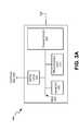
- FIG. 3Aillustrates exemplary components of the base station of FIG. 1 ;
- FIG. 3Billustrates exemplary functional components of the base station of FIG. 1 ;
- FIG. 4Aillustrates exemplary components of a user terminal of FIG. 1 ;
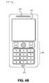
- FIG. 4Billustrates an exemplary implementation of the user terminal of FIG. 4A where the user terminal is a cellular radiotelephone;
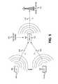
- FIG. 5depicts details of the network coding and relaying of data transmissions from a group of user terminals by a selected relay node to a base station at specified transmission time intervals;
- FIG. 6illustrates a “fair-per-node” time division scheme according to an exemplary embodiment
- FIG. 7illustrates a “fair-per-user terminal” time division scheme according to an exemplary embodiment
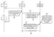
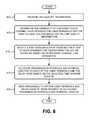
- FIG. 8is a flowchart that illustrates exemplary operations associated with selecting a time division scheme for time dividing a transmission resource and allocating transmission intervals and interval lengths to user terminals and a relay node involved in network coding based on the selected time division scheme;
- FIG. 9is an exemplary messaging diagram associated with the exemplary operations of FIG. 8 .
- FIG. 1illustrates an exemplary communications system 100 that may include multiple user terminals (UT) 110 - 1 through 110 -N connected to a network 120 via multiple relay nodes 130 - 1 through 130 -P and a base station 140 .
- UTs 110 - 1 through 110 -Nmay communicate 150 with devices 160 - 1 through 160 -M via relays 130 - 1 through 130 -P and base station 140 (and other components of network 120 not shown in FIG. 1 ).
- relay nodes 130 - 1 through 130 -P and base station 140may function as intermediate components of communications system 100 that may be used to facilitate end-to-end communication between UTs 110 - 1 through 110 -N and devices 160 - 1 through 160 -M.
- UTs 110 - 1 through 110 -Nmay include cellular radiotelephones, personal digital assistants (PDAs), Personal Communications System (PCS) terminals, laptop computers, palmtop computers, or any other types of devices or appliances that include a communication transceiver that permits the device to communicate with other devices via a wireless link.
- a PCS terminalmay combine a cellular radiotelephone with data processing, facsimile and data communications capabilities.
- a PDAmay include a radiotelephone, a pager, an Internet/intranet access device, a web browser, an organizer, calendars and/or a global positioning system (GPS) receiver.
- UTs 110 - 1 through 110 -Nmay be referred to as “pervasive computing” devices.
- Relay nodes 130 - 1 through 130 -Pmay include wireless nodes that receive data transmissions from multiple ones of UTs 110 - 1 through 110 -N and network code (described further below) and relay the received data transmissions to base station 140 .
- the network coding performed by relay nodes 130 - 1 through 130 -Pmay include analog or digital network coding.
- the digital network codingtypically involves linearly combining data from a group of user terminals, such as, for example, XOR bitwise encoding, Reed Solomon encoding, modulus encoding, or other types of operations for combining data bits from different user terminals of a group of user terminals.
- Devices 160 - 1 and 160 -Mmay include similar devices to UTs 110 - 1 through 110 -N and, in some implementations, may additionally include telephones (e.g., Plain Old Telephone system (POTs) telephones) that are connected to a Public Switched Telephone Network (PSTN).
- POTsPlain Old Telephone system
- PSTNPublic Switched Telephone Network
- Network(s) 120may include one or more networks of any type, including a local area network (LAN); a wide area network (WAN); a metropolitan area network (MAN); a telephone network, such as a PSTN or a PLMN; a satellite network; an intranet, the Internet; or a combination of networks.
- the PLMN(s)may further include a packet-switched sub-network, such as, for example, General Packet Radio Service (GPRS), Cellular Digital Packet Data (CDPD), or Mobile IP network.
- GPRSGeneral Packet Radio Service
- CDPDCellular Digital Packet Data
- FIG. 2illustrates an example of system 100 of FIG. 1 , where network 120 includes a PLMN 200 .
- network 120includes a PLMN 200 .
- UTs 110 - 1 and 110 -N and device 160may include cellular radiotelephones.
- PLMN 200may include one or more base station controllers (BSCs) 205 - 1 through 205 -Y (alternatively called “radio network controllers” (RNCs) in some implementations), multiple base stations (BSs) 140 and 210 - 1 through 210 -X along with their associated antenna arrays, one or more mobile switching centers (MSCs), such as MSC 215 , and one or more gateways (GWs), such as GW 220 .
- PLMN 200may additionally include components (not shown) for connecting PLMN 200 to a packet-switched network, such as a Packet Data Network (PDN), such that UTs 110 - 1 through 110 -N and device 160 can send or receive packet-switched data from the PDN.
- the components for connecting PLMN 200 to the PDNmay include a Serving GPRS Support Node (SGSN) and a Gateway GPRS Support Node (GGSN) (not shown).
- SGSNServing GPRS Support Node
- Base stations 140 and 210 - 1 through 210 -Xmay format the data transmitted to, or received from, the antenna arrays in accordance with existing techniques and may communicate with BSCs 205 - 1 through 205 -Y or with a device, such as device 160 .
- BSCs 205 - 1 through 205 -Ymay route received data to either MSC 215 or a base station (e.g., BSs 140 or 210 - 1 through 210 -X).
- MSC 215may route received data to BSC 205 - 1 , 205 -Y, or GW 220 .
- GW 220may route data received from an external domain (not shown) to an appropriate MSC (such as MSC 215 ), or from an MSC to an appropriate external domain.
- the external domainmay include a different PLMN or a PSTN.
- FIG. 3Aillustrates an exemplary implementation of BS 140 .
- Base stations 210 - 1 through 210 -Xmay be similarly configured.
- BS 140may include a transceiver 305 , a processing unit 310 , a memory 315 , an interface 320 and a bus 325 .
- Transceiver 305may include transceiver circuitry for transmitting and/or receiving symbol sequences using radio frequency signals via one or more antennas.
- Processing unit 310may include a processor, a microprocessor, or processing logic that may interpret and execute instructions. Processing unit 310 may perform all device data processing functions.
- Memory 315may provide permanent, semi-permanent, or temporary working storage of data and/or instructions for use by processing unit 310 in performing device processing functions.
- Memory 315may include read only memory (ROM), random access memory (RAM), large-capacity storage devices, such as a magnetic and/or optical recording medium and its corresponding drive, and/or other types of memory devices.
- Interface 320may include circuitry for interfacing with a link that connects to a BSC (e.g., BSC 205 - 1 or BSC 205 -Y).
- Bus 325may interconnect the various components of BS 140 to permit the components to communicate with one another.
- the configuration of components of BS 140 illustrated in FIG. 3Ais for illustrative purposes only. Other configurations with more, fewer, or a different arrangement of components may be implemented.
- FIG. 3Billustrates a functional diagram of base station 140 according to an exemplary implementation.
- the various functional components shown in FIG. 3Bmay be implemented by processing unit 310 , memory 315 , transceiver 305 , and possibly other components of base station 140 .
- Base station 140may include a link quality analysis unit 330 , a time division scheme selection unit 340 , an uplink/downlink transmission allocation unit 345 , and a notification message unit 350 .
- Link quality analysis unit 330may analyze link quality information that may be received from UTs 110 - 1 through 110 -N, received from a relay node 130 , and/or may be measured at base station 140 .
- the link quality informationmay include, for example, link quality information associated with the direct radio channel links between UTs 110 - 1 through 110 -N and base station 140 , link quality information associated with the links between UTs 110 - 1 through 110 -N and relay node 130 , and link quality information associated with the link between relay node 130 and base station 140 .
- Time division scheme selection unit 340may select a time division scheme to use for allocating transmission intervals and interval lengths (i.e., time slots and their respective lengths). For example, in a cellular system, the selected time division scheme may allocate transmission intervals and interval lengths on the uplink and/or downlink.
- the time division schemesmay include, among other time division schemes, a time division scheme to achieve “fairness-per-node,” a time division scheme to achieve “fairness-per-user terminal,” and a time division scheme to achieve “equal delay” per user terminal. Any of these time division schemes, either by themselves or in combination, may be selected to allocate uplink transmission intervals and interval lengths to each of UTs 110 - 1 through 110 -N and to relay node 130 for the network coding. As further described below, a cost function based algorithm may be used to optimize certain desired performance measures using one or more selected time division schemes.
- the “fairness-per-node” and “fairness-per-user terminal” time division schemesare described in more
- Uplink/downlink transmission allocation unit 345may allocate uplink and/or downlink transmission intervals and interval lengths based on the time division scheme selected by time division scheme selection unit 340 . Allocation of transmission intervals and interval lengths, for the exemplary “fair-per-node” and “fair-per-user terminal” time division schemes are described in further detail below with respect to FIGS. 6 and 7 .
- Notification message unit 350may construct one or more notification messages that may inform the selected relay node 130 and the user terminals 110 - 1 through 110 -N of the allocated transmission intervals and interval lengths.
- a single notification messagemay be constructed and sent to relay node 130 for relaying on to UTs 110 - 1 through 110 -N, or multiple notification messages may be constructed that can be sent to relay node 130 and directly to each of UTs 110 - 1 through 110 -N.
- FIG. 4Aillustrates exemplary components of a UT 110 .
- Relays 130 - 1 through 130 -Pmay be similarly configured.
- UT 110may include a transceiver 405 , a processing unit 410 , a memory 415 , an input device(s) 420 , an output device(s) 425 , and a bus 430 .
- Transceiver 405may include transceiver circuitry for transmitting and/or receiving symbol sequences using radio frequency signals via one or more antennas. Transceiver 405 may include, for example, a RAKE or a GRAKE receiver. Processing unit 410 may include a processor, microprocessor, or processing logic that may interpret and execute instructions. Processing unit 410 may perform all data processing functions for inputting, outputting, and processing of data including data buffering and device control functions, such as call processing control, user interface control, or the like.
- Memory 415may provide permanent, semi-permanent, or temporary working storage of data and instructions for use by processing unit 410 in performing device processing functions.
- Memory 415may include ROM, RAM, large-capacity storage devices, such as a magnetic and/or optical recording medium and its corresponding drive, and/or other types of memory devices.
- Input device(s) 420may include mechanisms for entry of data into UT 110 .
- input device(s) 420may include a key pad (not shown), a microphone (not shown) or a display unit (not shown).
- the key padmay permit manual user entry of data into UT 110 .
- the microphonemay include mechanisms for converting auditory input into electrical signals.
- the display unitmay include a screen display that may provide a user interface (e.g., a graphical user interface) that can be used by a user for selecting device functions.
- the screen display of the display unitmay include any type of visual display, such as, for example, a liquid crystal display (LCD), a plasma screen display, a light-emitting diode (LED) display, a cathode ray tube (CRT) display, an organic light-emitting diode (OLED) display, etc.
- LCDliquid crystal display
- LEDlight-emitting diode
- CRTcathode ray tube
- OLEDorganic light-emitting diode
- Output device(s) 425may include mechanisms for outputting data in audio, video and/or hard copy format.
- output device(s) 425may include a speaker (not shown) that includes mechanisms for converting electrical signals into auditory output.
- Output device(s) 425may further include a display unit that displays output data to the user.
- the display unitmay provide a graphical user interface that displays output data to the user.
- Bus 430may interconnect the various components of UT 110 to permit the components to communicate with one another.
- the configuration of components of UT 110 illustrated in FIG. 4Ais for illustrative purposes only. Other configurations with more, fewer, or a different arrangement of components may be implemented.
- FIG. 4Billustrates an exemplary implementation of UT 110 in which UT 110 includes a cellular radiotelephone.
- the cellular radiotelephonemay include a microphone 435 (e.g., of input device(s) 420 ) for entering audio information into UT 110 , a speaker 440 (e.g., of output device(s) 425 ) for providing an audio output from UT 110 , a keypad 445 (e.g., of input device(s) 420 ) for manual entry of data or selection of device functions, and a display 450 (e.g., of input device(s) 420 or output device(s) 425 ) that may visually display data to the user and/or which may provide a user interface that the user may use to enter data or to select device functions (in conjunction with keypad 445 ).
- a microphone 435e.g., of input device(s) 420
- a speaker 440e.g., of output device(s) 425
- FIG. 5illustrates the performance of network coding of data from a group of user terminals at a relay node and relaying of the network coded data to a base station.
- user terminal 110 - 1may transmit 510 data b 1 during transmission time interval T 1 to relay node 130 .
- Relay node 130may be selected from relay nodes 130 - 1 through 130 -P of FIG. 1 based on a selection scheme not described herein.
- User terminal 110 -Nmay also transmit 520 data b 2 during transmission time interval T 2 to relay node 130 .
- relay node 130may perform network coding 530 on the data, and then may relay/transmit 540 the network coded data to base station 140 during transmission time interval T 3 .
- relay node 130 - 1is depicted as using Exclusive OR operations (XOR- ⁇ ) to network code the data b 1 and b 2 received from UTs 110 - 1 and 110 -N.
- XOR- ⁇Exclusive OR operations
- different network coding schemesmay be used.
- the relative time division of transmission phasesmay be achieved according to various time division schemes.
- the various time division schemesmay allocate different transmission intervals and interval lengths (e.g., uplink and/or downlink) for each of the time intervals T 1 , T 2 and T 3 shown in FIG. 5 .
- one time division schememay achieve “fairness-per-node.”
- Another time division schememay attempt to achieve “fairness-per-user terminal.”
- a further time division schememay attempt to achieve equal delay per user terminal.
- time division schemes or other time division schemesmay be selected to allocate uplink transmission intervals and interval lengths to each of UTs 110 - 1 through 110 -N and to relay node 130 .
- the other time division schemesmay include schemes based on channel quality measures of different links in the system.
- the other time division schemesmay be based on channel quality measures associated with the links between the user terminals and the relay node, between the relay node and the base station and/or between the user terminals and the base station.
- a cost function based algorithmmay be used to optimize certain desired performance measures using one or more selected time division schemes.
- Signal-to-Noise and Interference Ratios (SINR) equations associated with the network coding transmissions shown in FIG. 5may be derived and used to demonstrate how different time division schemes lead to different capacity equations that may be used to optimize certain desired performance measures.
- a first user terminale.g., user terminal 110 - 1
- OFDMOrthogonal Frequency Division Multiplexing
- H i,j (k)is the radio channel between the transmitter of the j th user terminal of BS i and the receiver of BS 1 ,
- s i,j (k)is the modulated signal of the j th user terminal in BS i,
- w 1 (k)is the thermal noise
- N bis the number of base stations in the system.
- the signal received at relay node 130 after T 1may be expressed as:
- H r,i,jis the radio channel between the transmitter of the j th user terminal of BS i and the receiver of the active relay node of BS 1 .
- the SINR at base station 140 after T 1 , ⁇ 1may be expressed as:
- the SINR for user terminal 1 at relay node 130 after T 1is denoted as ⁇ r,1 and may be expressed as:
- the signal received at base station 140 after user terminal 2 (e.g., UT 110 -N) has transmitted during T 2may be expressed as:
- the signal received at relay node 130 after T 2may be expressed as:
- the SINR at base station 140 after T 2 , ⁇ 2may be expressed as
- the SINR for user terminal 2 (e.g., UT 110 -N) at relay node 130 after T 2is denoted as ⁇ r,2 and may be expressed as:
- relay node 130may transmit the network-coded signal.
- the signal received at base station 140 after T 3may be expressed as
- the total transmission time Tmay be divided into three equal time slots given by:
- T 1may be assigned to user terminal 1 (e.g., UT 110 - 1 )
- T 2may be assigned to user terminal 2 (e.g., UT 110 -N)
- T 3may be assigned to relay node 130 .
- the “strong” user terminale.g., the user terminal having the strongest direct radio channel connection to base station 140
- the “weak” user terminale.g., the user terminal having the weakest direct radio channel connection to base station 140
- the remaining two thirds of the total transmission time Ti.e., one third through its own transmission time, and another third through the relay node transmission time.
- the sum capacity of the “fair-per-node” time division scheme of FIG. 6may be expressed as:
- the total transmission time Tmay be divided into three time slots given by:
- Time slot T 1may be assigned to the “strong” user terminal
- time slot T 2may be assigned to the “weak” user terminal
- time slot T 3may be assigned to relay node 130 .
- the “strong” user terminal and the “weak” user terminalwill each have access to half of the transmission duration T.
- the sum capacity of the time division scheme of FIG. 7may be expressed as:
- time division scheme 21 2 ⁇ [ log 2 ⁇ ( 1 + ⁇ 1 ′ ) + 1 2 ⁇ log 2 ⁇ ( 1 + ⁇ 2 ′ ) ] Eqn . ⁇ ( 16 ) Due to the log 2 operator in the capacity equation, it would be expected that time division scheme 2 may provide a comparable performance to time division scheme 1 at low SINR regions, whereas time division scheme 2 may provide substantially higher gains at high SINR regions, thus, providing a higher total system throughput.
- Time division schemes 1 and 2may be combined in some implementations to form a cost-based algorithm.
- One example of such a combinationis choosing the time division scheme (e.g., scheme 1 or scheme 2) that maximizes the sum-capacity at a given time period.
- a time division scheme t*may be selected that maximizes the sum capacity according to the following expression:
- t *argmax t ⁇ ⁇ Scheme ⁇ ⁇ 1 , Scheme ⁇ ⁇ 2 ⁇ ⁇ C ⁇ ( U 1 , U 2 ) Eqn . ⁇ ( 17 )
- a time division scheme t*may be selected that minimizes generated interference according to the expression:
- the interferencemay be associated with links between the user terminals and the relay node, between the relay node and the base station, between the user terminals and base station, etc.
- Exemplary cost-based algorithmssuch as those represented by Eqns. (17) and (18), may permit “fairness” to be controlled through the selected time division scheme and a parameter (e.g., a given performance measure) associated with network coding of data transmitted between the plurality of user terminals and the base station via the relay node to be optimized.
- FIG. 8is a flowchart that illustrates exemplary operations associated with selecting a time division scheme for time dividing a transmission resource (e.g., uplink and/or downlink in a cellular system) and allocating transmission intervals and interval lengths to user terminals and a relay node involved in network coding based on the selected time division scheme.
- the exemplary operations of FIG. 8may be implemented by base station 140 .
- the exemplary operations of FIG. 8are described below with reference to the messaging diagram of FIG. 9 .
- the exemplary operationsmay begin with the receipt of link quality information (block 800 ).
- the link quality informationmay include, for example, Signal-to-Interference-Noise-Ratio (SINR) and/or estimates of channel conditions measured at one or more of UTs 110 - 1 through 110 -N, relay node 130 - 1 , or base station 140 .
- SINRSignal-to-Interference-Noise-Ratio
- each of UTs 110 - 1 through 110 -Nmay measure a link quality associated with its link to the selected relay node (e.g., relay node 130 - 1 in FIG. 9 ) and may send the link quality information to the selected relay node (as shown in FIG. 9 ), or directly to base station 140 .
- the received link quality datamay permit base station 140 to identify which of UTs 110 - 1 through 110 -N that has the weakest direct radio channel connection to base station 140 , and identify which of UTs 110 - 1 through 110 -N that has the strongest direct radio channel connection to base station 140 .
- FIG. 9depicts relay node 130 - 1 obtaining 910 link quality data associated with links to UTs 110 - 1 and 110 -N. As further shown in FIG. 9 , relay node 130 - 1 may subsequently send link quality data 915 to base station 140 .
- the strength of the direct radio channel links between the user terminals and the serving base stationmay be determined based on the received link quality information (block 805 ).
- Base station 140may evaluate the link quality information received in block 800 , which may include link quality information associated with direct links between UTs 110 - 1 through 110 -N, and may determine the relative strengths of the direct radio channel inks between UTs 110 - 1 through 110 -N and base station 140 .
- the user terminal with the direct radio channel link having the weakest strengthmay be referred to herein as the “weak” user terminal.
- the user terminal with the direct radio channel link having the strongest strengthmay be referred to herein as the “strong” user terminal.
- FIG. 9depicts base station 140 determining 920 connection strengths of direct links between the UTs and base station 140 .
- a time division schememay be selected from multiple time division schemes for time dividing the uplink and/or downlink based on the determined channel link strengths (block 810 ).
- the multiple time division schemesmay include, but are not limited to, the “fair-per-node” scheme (scheme 1) and/or “fair-per-user terminal” scheme (scheme 2), described above.
- the multiple time division schemesmay include, but are not limited to, the “fair-per-node” scheme (scheme 1) and/or “fair-per-user terminal” scheme (scheme 2), described above.
- the plurality of time division schemesmay further include a time division scheme that attempts to equalize delay per user terminal.
- the multiple time division schemesmay include other time division schemes that are, for example, based on channel quality measures of different links in the system. For example, the other time division schemes may be based on channel quality measures associated with the links between the user terminals and the relay node, between the relay node and the base station and/or between the user terminals and the base station.
- Selection of a time division schememay, in some implementations, include choosing a time division scheme that optimizes a performance measure (e.g., a parameter associated with the network coding process). For example, as expressed in Equations (17) and (18) above, a time division scheme (e.g., scheme 1 or scheme 2) may be selected that maximizes a sum capacity and/or minimizes a generated interference.
- the determined channel link strengths(block 805 ) may be used in block 810 to identify user terminals 110 - 1 through 110 -N as a “weak” user terminal or a “strong” user terminal for purposes of allocating transmission intervals and interval lengths, as shown in FIGS. 6 and 7 , and as described below with respect to block 815 .
- FIG. 9depicts base station 140 selecting 925 a time division scheme from multiple time division schemes based on determined link connection strengths.
- Transmission intervals and interval lengthsmay be allocated to each of the user terminals and to the relay node based on the selected time division scheme (block 815 ). As already described above with respect to FIG. 6 , if a “fair-per-node” time division scheme (scheme 1) is selected, the total transmission time T may be divided into three equal time slots
- one time slotmay be assigned to each node, e.g., T 1 may be assigned to user terminal 1 (e.g., UT 110 - 1 ), T 2 may be assigned to user terminal 2 (e.g., UT 110 -N) and T 3 may be assigned to relay node 130 - 1 .
- the “strong” user terminale.g., the user terminal having the strongest direct radio channel connection to base station 140
- the “weak” user terminale.g., the user terminal having the weakest direct radio channel connection to base station 140
- the remaining two thirds of the total transmission time Ti.e., one third through its own transmission time, and another third through the relay node transmission time.
- the total transmission time Tmay be divided into three
- time slotswhere time slot T 1 may be assigned to the “strong” user terminal, time slot T 2 may be assigned to the “weak” user terminal, and time slot T 3 may be assigned to relay node 130 - 1 .
- the “strong” user terminal and the “weak” user terminalwill each have access to half of the transmission duration T.
- FIG. 9depicts base station 140 allocating 930 transmission intervals and interval lengths to the UTs and the selected relay node based on the selected time division scheme.
- a message(s)may be sent to inform the user terminals and the relay node of their respective allocated transmission intervals and interval lengths (block 820 ).
- the notification messagemay be sent to relay node 130 - 1 for relaying to user terminals 110 - 1 through 110 -N, or messages may be sent individually to relay node 130 - 1 , and directly to UTs 110 - 1 through 110 -N that inform the user terminals and relay node of their respective transmission intervals allocated in block 815 .
- FIG. 9depicts base station 140 sending an exemplary notification message 935 to relay node 130 - 1 .
- Relay node 130 - 1may, subsequently, relay notification message 935 on to UTs 110 - 1 through 110 -N (not shown).
- relay node 130 - 1may network code data transmissions from UTs 110 - 1 through 110 -N, based on the transmission time intervals and interval lengths allocated during the exemplary operations of FIG. 8 , as generally described above with respect to FIG. 5 .
- aspects of the inventionmay also be implemented in methods and/or computer program products. Accordingly, the invention may be embodied in hardware and/or in software (including firmware, resident software, microcode, etc.). Furthermore, the invention may take the form of a computer program product on a computer-usable or computer-readable storage medium having computer-usable or computer-readable program code embodied in the medium for use by or in connection with an instruction execution system.
- the actual software code or specialized control hardware used to implement the embodiments described hereinis not limiting of the invention. Thus, the operation and behavior of the embodiments were described without reference to the specific software code—it being understood that one of ordinary skill in the art would be able to design software and control hardware to implement the aspects based on the description herein.
- logicmay include hardware, such as an application specific integrated circuit or field programmable gate array, or a combination of hardware and software.
Landscapes
- Engineering & Computer Science (AREA)
- Computer Networks & Wireless Communication (AREA)
- Signal Processing (AREA)
- Quality & Reliability (AREA)
- Mobile Radio Communication Systems (AREA)
Abstract
Description
Similarly, the signal received at
The signal received at
The SINR at
The SINR for user terminal2 (e.g., UT110-N) at
During the third hop,
- where Gr,iis the channel between the transmitter of the active relay of BS i and the receiver of
BS 1, and didenotes the network-coded transmitted signal from the active relay of BS i.
The resulting SINR, Γ3is then given by:
- where Gr,iis the channel between the transmitter of the active relay of BS i and the receiver of
- where pr,iis the transmitted power of the active relay in BS i.
The transmitted network coded data may then be decoded based on the following algorithm. Without loss of generality, let us assume that user terminal1 (UT110-1) has a better link tobase station 140 than user terminal2 (UT110-N), i.e., Γ1>Γ2. Then the data ofuser terminal 1 may be decoded based on its SINR through the direct link tobase station 140. However, this data still needs to be transmitted at a rate so that it can be decoded atrelay node 130 so that it can further be used to decode the network coded data (e.g., XOR-ed data) transmitted byrelay node 130. The resulting equivalent SINR ofuser terminal 1 may then be given by:
Γ′1=min{Γ1;Γr,1} Eqn. (11)
Consequently, the relayed signal may then be used (after being decoded against the transmission of user terminal1) in order to improve the equivalent SINR of the weak user terminal in the pair. Assuming maximum ratio combining (MRC), the equivalent SINR ofuser terminal 2 may then be given by:
Γ′2=min{Γ2+Γ3;Γr,2} Eqn. (12)
The resulting sum capacity equation may be based on the amount of time each node is given to transmit its data.
- where pr,iis the transmitted power of the active relay in BS i.
One time slot may be assigned to each node, e.g., T1may be assigned to user terminal1 (e.g., UT110-1), T2may be assigned to user terminal2 (e.g., UT110-N) and T3may be assigned to relay
Time slot T1may be assigned to the “strong” user terminal, time slot T2may be assigned to the “weak” user terminal, and time slot T3may be assigned to relay
Due to the log2operator in the capacity equation, it would be expected that
As another example, a time division scheme t* may be selected that minimizes generated interference according to the expression:
- where the interference may be measured at base stations other than
base station 140, at other relay nodes, and/or at other user terminals.
- where the interference may be measured at base stations other than
where one time slot may be assigned to each node, e.g., T1may be assigned to user terminal1 (e.g., UT110-1), T2may be assigned to user terminal2 (e.g., UT110-N) and T3may be assigned to relay node130-1. With such time slot assignments, the “strong” user terminal (e.g., the user terminal having the strongest direct radio channel connection to base station140) will have access to one third of the total transmission time T, whereas the “weak” user terminal (e.g., the user terminal having the weakest direct radio channel connection to base station140) will have access to the remaining two thirds of the total transmission time T (i.e., one third through its own transmission time, and another third through the relay node transmission time).
time slots where time slot T1may be assigned to the “strong” user terminal, time slot T2may be assigned to the “weak” user terminal, and time slot T3may be assigned to relay node130-1. With the relative time division shown in
Claims (16)
Applications Claiming Priority (1)
| Application Number | Priority Date | Filing Date | Title |
|---|---|---|---|
| PCT/SE2008/050925WO2010019083A1 (en) | 2008-08-15 | 2008-08-15 | Relative time division for network coding |
Publications (2)
| Publication Number | Publication Date |
|---|---|
| US20110142013A1 US20110142013A1 (en) | 2011-06-16 |
| US8665866B2true US8665866B2 (en) | 2014-03-04 |
Family
ID=41669075
Family Applications (1)
| Application Number | Title | Priority Date | Filing Date |
|---|---|---|---|
| US13/058,388Expired - Fee RelatedUS8665866B2 (en) | 2008-08-15 | 2008-08-15 | Relative time division for network coding |
Country Status (3)
| Country | Link |
|---|---|
| US (1) | US8665866B2 (en) |
| EP (1) | EP2313992A4 (en) |
| WO (1) | WO2010019083A1 (en) |
Cited By (2)
| Publication number | Priority date | Publication date | Assignee | Title |
|---|---|---|---|---|
| US10517092B1 (en) | 2018-06-04 | 2019-12-24 | SparkMeter, Inc. | Wireless mesh data network with increased transmission capacity |
| US11647550B2 (en) | 2020-04-17 | 2023-05-09 | Rockwell Collins, Inc. | 4G automatic link establishment (ALE) with improved two-way link quality analysis (LQA) exchange |
Families Citing this family (15)
| Publication number | Priority date | Publication date | Assignee | Title |
|---|---|---|---|---|
| EP2313992A4 (en) | 2008-08-15 | 2014-09-17 | Unwired Planet Internat Ltd | Relative time division for network coding |
| KR101659336B1 (en)* | 2009-04-06 | 2016-09-23 | 삼성전자주식회사 | System and method for managing communication in a wireless communication network |
| EP2472936A4 (en)* | 2009-09-18 | 2015-11-11 | Sony Corp | RELAY STATION, RELAY METHOD, AND WIRELESS COMMUNICATION DEVICE |
| US9042294B2 (en)* | 2009-10-05 | 2015-05-26 | Futurewei Technologies, Inc. | System and method for relaying transmissions in wireless communications |
| CN101854663A (en)* | 2010-04-30 | 2010-10-06 | 华为技术有限公司 | Data transmission device, method and communication system |
| EP2612459B1 (en) | 2010-09-03 | 2014-06-04 | Telefonaktiebolaget L M Ericsson (publ) | Method and arrangement for resource allocation for coded multidirectional relaying |
| EP2630831A4 (en)* | 2010-10-20 | 2016-10-26 | Nokia Technologies Oy | Interference-aware scheduling with broadcast/multicast signaling |
| GB2493785B (en) | 2011-08-19 | 2016-04-20 | Sca Ipla Holdings Inc | Wireless communications system and method |
| GB2493784B (en) | 2011-08-19 | 2016-04-20 | Sca Ipla Holdings Inc | Wireless communications system and method |
| KR101915473B1 (en)* | 2012-06-29 | 2018-11-06 | 삼성전자주식회사 | Method for decision pair of target receiver and target transmitter distributedly and concentratedly using cooperation header in a multi-hop network performing interference neutralization |
| CN103051427B (en)* | 2013-01-25 | 2015-05-20 | 西安电子科技大学 | Duplex wireless relay communication method based on network coding |
| KR102115401B1 (en)* | 2013-04-24 | 2020-05-26 | 삼성전자주식회사 | Method and apparatus for managing packet in a system surpporting a network coding scheme |
| US9007984B1 (en)* | 2013-11-19 | 2015-04-14 | The Aerospace Corporation | Network coding for satellite communications |
| EP2887732B1 (en)* | 2013-12-19 | 2017-06-14 | Sony Corporation | Method for operating a user equipment in a wireless radio network |
| WO2020258301A1 (en)* | 2019-06-28 | 2020-12-30 | 华为技术有限公司 | Communication method and apparatus |
Citations (48)
| Publication number | Priority date | Publication date | Assignee | Title |
|---|---|---|---|---|
| US4028497A (en)* | 1975-04-04 | 1977-06-07 | Nippon Electric Company, Ltd. | Acquisition technique for time division multiple access communication system |
| US5491741A (en)* | 1992-10-23 | 1996-02-13 | At&T Corp. | Prioritizing a multiple access channel in a wireless telephone system |
| US5530700A (en)* | 1994-07-29 | 1996-06-25 | Motorola, Inc. | Method and device for controlling time slot contention to provide fairness between a plurality of types of subscriber units in a communication system |
| US5663957A (en)* | 1995-07-12 | 1997-09-02 | Ericsson Inc. | Dual mode satellite/cellular terminal |
| US5999538A (en)* | 1996-07-02 | 1999-12-07 | Extreme Networks, Inc. | Method and apparatus for arbitrating data transmission in a CSMA/CD LAN |
| US20010053142A1 (en)* | 2000-06-20 | 2001-12-20 | Matsushita Electric Industrial Co., Ltd | Radio communication system |
| US6396832B1 (en)* | 1998-09-04 | 2002-05-28 | 3Com Corporation | Method and apparatus for optimizing a switched arbitrated loop for maximum access fairness |
| US20030021245A1 (en)* | 2001-07-24 | 2003-01-30 | Luc Haumonte | System and method of classifying remote users according to link quality, and scheduling wireless transmission of information to the to the users based upon the classifications |
| US6532224B1 (en)* | 1999-05-10 | 2003-03-11 | Ericsson, Inc. | Method, systems, and terminals for assigning control channel time slots for group and individual pages |
| US20040014477A1 (en)* | 2002-05-23 | 2004-01-22 | Ntt Docomo, Inc. | Radio communication system, radio terminal, base station, control equipment and communication method |
| US20040013101A1 (en)* | 2002-05-23 | 2004-01-22 | Akin Huseyin C. | Method and system for allocating power and scheduling packets in one or more cells of a wireless communication system or network |
| US20040028018A1 (en)* | 2002-01-10 | 2004-02-12 | Harris Corporation, Corporation Of The State Of Delaware | Wireless communication system with enhanced time slot allocation and interference avoidance/mitigation features and related methods |
| US20040037251A1 (en)* | 2002-08-21 | 2004-02-26 | Ofer Shneyour | Method and system for transmitting and receiving data in a TDMA frequency hopping system utilizing frequency diversity |
| US20040071163A1 (en)* | 2002-10-15 | 2004-04-15 | Hogberg Shawn W. | Scheduling method for supplemental channel resource |
| US20040213197A1 (en)* | 1999-05-21 | 2004-10-28 | Ofer Zimmerman | Method and apparatus for a self-correcting bandwidth request/grant protocol in a wireless communication system |
| US20040214577A1 (en)* | 2003-04-24 | 2004-10-28 | Lucent Technologies, Inc. | Methods and apparatus for planning wireless data networks using analytical modeling of user level performance |
| US20040264492A1 (en)* | 1999-07-19 | 2004-12-30 | Blahut Donald E. | Ranging arrangement and method for TDMA communications |
| US20050094675A1 (en)* | 2003-11-03 | 2005-05-05 | Naga Bhushan | Method, apparatus, and system for data transmission and processing in a wireless communication environment |
| US20050124352A1 (en)* | 2003-12-05 | 2005-06-09 | Fernandez-Corbaton Ivan J. | Systems and methods for adaptively allocating resources between a dedicated reference signal and a traffic signal |
| US20050169389A1 (en)* | 2004-02-04 | 2005-08-04 | Fischer Gerald R. | Increased user capacity ultra wideband (UWB) signal formatting scheme |
| US20050265223A1 (en)* | 2004-05-14 | 2005-12-01 | Samsung Electronics Co., Ltd. | Method and apparatus for scheduling downlink channels in an orthogonal frequency division multiple access system and a system using the same |
| WO2007075129A1 (en) | 2005-12-27 | 2007-07-05 | Telefonaktiebolaget Lm Ericsson (Publ) | Multi-cellular load dependent scheduling |
| US20070201400A1 (en) | 2006-02-07 | 2007-08-30 | Samsung Electronics Co., Ltd. | Opportunistic packet scheduling apparatus and method in multihop relay wireless access communication system |
| US7313110B2 (en)* | 2002-10-09 | 2007-12-25 | Telefonaktiebolaget L.M. Ericsson | Methods, systems, and computer program products for allocating bandwidth in a radio packet data system based on data rate estimates determined for one or more idle transmitter/sector scenarios |
| US20080008206A1 (en)* | 2006-05-29 | 2008-01-10 | Samsung Electronics Co., Ltd. | Method and apparatus for allocating frequency resources in a wireless communication system supporting frequency division multiplexing |
| US20080031217A1 (en)* | 2004-07-13 | 2008-02-07 | France Telecom | Method For Selecting Receiving Stations In A Data Radio Transmitting System |
| US20080057969A1 (en)* | 2006-09-05 | 2008-03-06 | Motorola, Inc. | Method and apparatus for providing channel quality feedback in a wireless communication system |
| US20080117881A1 (en)* | 2004-03-31 | 2008-05-22 | Matsushita Electric Industrial Co., Ltd. | Method For Performing A Scheduling Algorithm With A Minimum Resource Parameter And Method Of Calculating Same |
| US20080153495A1 (en)* | 2006-12-20 | 2008-06-26 | Nec Corporation | Mobile communication system, handover control method, radio base station, and mobile station |
| US20080188177A1 (en)* | 2004-10-21 | 2008-08-07 | Matsushita Electric Industrial Co., Ltd. | Method And System For Identifying A Relay Mobile Station In A Wireless Communication Network |
| US20080198815A1 (en)* | 2007-02-21 | 2008-08-21 | Itt Manufacturing Enterprises, Inc. | Nearly Collision-Free Channel Access System and Method |
| WO2009126079A1 (en) | 2008-04-11 | 2009-10-15 | Telefonaktiebolaget L M Ericsson (Publ) | Network coded data communication |
| US20090268790A1 (en)* | 2008-04-29 | 2009-10-29 | Samsung Electronics Co., Ltd. | Methods and apparatus for network coding in a communication system |
| US20090285196A1 (en)* | 2008-05-15 | 2009-11-19 | Cellco Partnership D/B/A Verizon Wireless | Scheduling with quality of service support in wireless system |
| US20090285148A1 (en)* | 2008-05-19 | 2009-11-19 | Microsoft Corporation | Natural network coding for multi-hop wireless network |
| US20100034185A1 (en)* | 2004-10-25 | 2010-02-11 | Telefonaktiebolaget Lm Ericsson | Radio quality based channel resource management |
| US7719981B2 (en)* | 1999-02-26 | 2010-05-18 | Bitbytebit Information Services, Inc. | Adaptive transmission in multi-access asynchronous channels |
| US20100146274A1 (en)* | 2007-06-18 | 2010-06-10 | Telefonaktiebolaget L M Ericsson (Publ) | Security for software defined radio terminals |
| US7751421B2 (en)* | 2004-12-29 | 2010-07-06 | Alcatel Lucent | Traffic generator and monitor |
| US20100290406A1 (en)* | 2006-06-19 | 2010-11-18 | Ntt Docomo, Inc. | Base station and transmission method |
| US7839882B2 (en)* | 2002-10-31 | 2010-11-23 | Qualcomm Incorporated | Resource allocation in a wireless communication system |
| US20110134828A1 (en) | 2008-08-15 | 2011-06-09 | Telefonaktiebolaget Lm Ericsson (Publ) | Relay Node Selection for Network Coding |
| US20110142013A1 (en) | 2008-08-15 | 2011-06-16 | Telefonaktiebolaget Lm Ericsson (Publ) | Relative Time Division for Network Coding |
| US20110158646A1 (en)* | 2009-12-25 | 2011-06-30 | Industrial Technology Research Institute | Medium access control device and method for optical packet-switched metro wdm slotted-ring networks |
| US8036164B1 (en)* | 2000-01-11 | 2011-10-11 | At&T Intellectual Property Ii, L.P. | System and method for selecting a transmission channel in a wireless communication system that includes an adaptive array |
| US8064392B2 (en)* | 2006-09-26 | 2011-11-22 | Inha Industry Partnership Institute | Method for dynamic resource allocation of uplink and downlink in OFDMA/TDD cellular system |
| US20120263100A1 (en)* | 2007-08-27 | 2012-10-18 | Jun Yuan | Mimo based network coding network |
| US20130012119A1 (en)* | 2008-08-12 | 2013-01-10 | Jianglei Ma | Enabling downlink transparent relay in a wireless communications network |
- 2008
- 2008-08-15EPEP08794150.6Apatent/EP2313992A4/ennot_activeWithdrawn
- 2008-08-15USUS13/058,388patent/US8665866B2/ennot_activeExpired - Fee Related
- 2008-08-15WOPCT/SE2008/050925patent/WO2010019083A1/enactiveApplication Filing
Patent Citations (51)
| Publication number | Priority date | Publication date | Assignee | Title |
|---|---|---|---|---|
| US4028497A (en)* | 1975-04-04 | 1977-06-07 | Nippon Electric Company, Ltd. | Acquisition technique for time division multiple access communication system |
| US5491741A (en)* | 1992-10-23 | 1996-02-13 | At&T Corp. | Prioritizing a multiple access channel in a wireless telephone system |
| US5530700A (en)* | 1994-07-29 | 1996-06-25 | Motorola, Inc. | Method and device for controlling time slot contention to provide fairness between a plurality of types of subscriber units in a communication system |
| US5663957A (en)* | 1995-07-12 | 1997-09-02 | Ericsson Inc. | Dual mode satellite/cellular terminal |
| US5999538A (en)* | 1996-07-02 | 1999-12-07 | Extreme Networks, Inc. | Method and apparatus for arbitrating data transmission in a CSMA/CD LAN |
| US6396832B1 (en)* | 1998-09-04 | 2002-05-28 | 3Com Corporation | Method and apparatus for optimizing a switched arbitrated loop for maximum access fairness |
| US7719981B2 (en)* | 1999-02-26 | 2010-05-18 | Bitbytebit Information Services, Inc. | Adaptive transmission in multi-access asynchronous channels |
| US6532224B1 (en)* | 1999-05-10 | 2003-03-11 | Ericsson, Inc. | Method, systems, and terminals for assigning control channel time slots for group and individual pages |
| US20040213197A1 (en)* | 1999-05-21 | 2004-10-28 | Ofer Zimmerman | Method and apparatus for a self-correcting bandwidth request/grant protocol in a wireless communication system |
| US20040264492A1 (en)* | 1999-07-19 | 2004-12-30 | Blahut Donald E. | Ranging arrangement and method for TDMA communications |
| US8036164B1 (en)* | 2000-01-11 | 2011-10-11 | At&T Intellectual Property Ii, L.P. | System and method for selecting a transmission channel in a wireless communication system that includes an adaptive array |
| US20010053142A1 (en)* | 2000-06-20 | 2001-12-20 | Matsushita Electric Industrial Co., Ltd | Radio communication system |
| US20030021245A1 (en)* | 2001-07-24 | 2003-01-30 | Luc Haumonte | System and method of classifying remote users according to link quality, and scheduling wireless transmission of information to the to the users based upon the classifications |
| US20040028018A1 (en)* | 2002-01-10 | 2004-02-12 | Harris Corporation, Corporation Of The State Of Delaware | Wireless communication system with enhanced time slot allocation and interference avoidance/mitigation features and related methods |
| US20040014477A1 (en)* | 2002-05-23 | 2004-01-22 | Ntt Docomo, Inc. | Radio communication system, radio terminal, base station, control equipment and communication method |
| US20040013101A1 (en)* | 2002-05-23 | 2004-01-22 | Akin Huseyin C. | Method and system for allocating power and scheduling packets in one or more cells of a wireless communication system or network |
| US7277411B2 (en)* | 2002-08-21 | 2007-10-02 | D.S.P. Group Ltd. | Method and system for transmitting and receiving data in a TDMA frequency hopping system utilizing frequency diversity |
| US20040037251A1 (en)* | 2002-08-21 | 2004-02-26 | Ofer Shneyour | Method and system for transmitting and receiving data in a TDMA frequency hopping system utilizing frequency diversity |
| US7313110B2 (en)* | 2002-10-09 | 2007-12-25 | Telefonaktiebolaget L.M. Ericsson | Methods, systems, and computer program products for allocating bandwidth in a radio packet data system based on data rate estimates determined for one or more idle transmitter/sector scenarios |
| US20040071163A1 (en)* | 2002-10-15 | 2004-04-15 | Hogberg Shawn W. | Scheduling method for supplemental channel resource |
| US7839882B2 (en)* | 2002-10-31 | 2010-11-23 | Qualcomm Incorporated | Resource allocation in a wireless communication system |
| US20040214577A1 (en)* | 2003-04-24 | 2004-10-28 | Lucent Technologies, Inc. | Methods and apparatus for planning wireless data networks using analytical modeling of user level performance |
| US20050094675A1 (en)* | 2003-11-03 | 2005-05-05 | Naga Bhushan | Method, apparatus, and system for data transmission and processing in a wireless communication environment |
| US20050124352A1 (en)* | 2003-12-05 | 2005-06-09 | Fernandez-Corbaton Ivan J. | Systems and methods for adaptively allocating resources between a dedicated reference signal and a traffic signal |
| US20050169389A1 (en)* | 2004-02-04 | 2005-08-04 | Fischer Gerald R. | Increased user capacity ultra wideband (UWB) signal formatting scheme |
| US20080117881A1 (en)* | 2004-03-31 | 2008-05-22 | Matsushita Electric Industrial Co., Ltd. | Method For Performing A Scheduling Algorithm With A Minimum Resource Parameter And Method Of Calculating Same |
| US20050265223A1 (en)* | 2004-05-14 | 2005-12-01 | Samsung Electronics Co., Ltd. | Method and apparatus for scheduling downlink channels in an orthogonal frequency division multiple access system and a system using the same |
| US20080031217A1 (en)* | 2004-07-13 | 2008-02-07 | France Telecom | Method For Selecting Receiving Stations In A Data Radio Transmitting System |
| US20080188177A1 (en)* | 2004-10-21 | 2008-08-07 | Matsushita Electric Industrial Co., Ltd. | Method And System For Identifying A Relay Mobile Station In A Wireless Communication Network |
| US20100034185A1 (en)* | 2004-10-25 | 2010-02-11 | Telefonaktiebolaget Lm Ericsson | Radio quality based channel resource management |
| US7751421B2 (en)* | 2004-12-29 | 2010-07-06 | Alcatel Lucent | Traffic generator and monitor |
| US20110045838A1 (en)* | 2005-12-27 | 2011-02-24 | Telefonaktiebolaget Lm Ericsson | Multi-cellular load dependent scheduling |
| WO2007075129A1 (en) | 2005-12-27 | 2007-07-05 | Telefonaktiebolaget Lm Ericsson (Publ) | Multi-cellular load dependent scheduling |
| US20070201400A1 (en) | 2006-02-07 | 2007-08-30 | Samsung Electronics Co., Ltd. | Opportunistic packet scheduling apparatus and method in multihop relay wireless access communication system |
| US20080008206A1 (en)* | 2006-05-29 | 2008-01-10 | Samsung Electronics Co., Ltd. | Method and apparatus for allocating frequency resources in a wireless communication system supporting frequency division multiplexing |
| US20100290406A1 (en)* | 2006-06-19 | 2010-11-18 | Ntt Docomo, Inc. | Base station and transmission method |
| US20080057969A1 (en)* | 2006-09-05 | 2008-03-06 | Motorola, Inc. | Method and apparatus for providing channel quality feedback in a wireless communication system |
| US8064392B2 (en)* | 2006-09-26 | 2011-11-22 | Inha Industry Partnership Institute | Method for dynamic resource allocation of uplink and downlink in OFDMA/TDD cellular system |
| US20080153495A1 (en)* | 2006-12-20 | 2008-06-26 | Nec Corporation | Mobile communication system, handover control method, radio base station, and mobile station |
| US20080198815A1 (en)* | 2007-02-21 | 2008-08-21 | Itt Manufacturing Enterprises, Inc. | Nearly Collision-Free Channel Access System and Method |
| US20100146274A1 (en)* | 2007-06-18 | 2010-06-10 | Telefonaktiebolaget L M Ericsson (Publ) | Security for software defined radio terminals |
| US20120263100A1 (en)* | 2007-08-27 | 2012-10-18 | Jun Yuan | Mimo based network coding network |
| WO2009126079A1 (en) | 2008-04-11 | 2009-10-15 | Telefonaktiebolaget L M Ericsson (Publ) | Network coded data communication |
| US20110026429A1 (en) | 2008-04-11 | 2011-02-03 | Telefonaktiebolaget Lm Ericsson (Publ) | Network Coded Data Communication |
| US20090268790A1 (en)* | 2008-04-29 | 2009-10-29 | Samsung Electronics Co., Ltd. | Methods and apparatus for network coding in a communication system |
| US20090285196A1 (en)* | 2008-05-15 | 2009-11-19 | Cellco Partnership D/B/A Verizon Wireless | Scheduling with quality of service support in wireless system |
| US20090285148A1 (en)* | 2008-05-19 | 2009-11-19 | Microsoft Corporation | Natural network coding for multi-hop wireless network |
| US20130012119A1 (en)* | 2008-08-12 | 2013-01-10 | Jianglei Ma | Enabling downlink transparent relay in a wireless communications network |
| US20110142013A1 (en) | 2008-08-15 | 2011-06-16 | Telefonaktiebolaget Lm Ericsson (Publ) | Relative Time Division for Network Coding |
| US20110134828A1 (en) | 2008-08-15 | 2011-06-09 | Telefonaktiebolaget Lm Ericsson (Publ) | Relay Node Selection for Network Coding |
| US20110158646A1 (en)* | 2009-12-25 | 2011-06-30 | Industrial Technology Research Institute | Medium access control device and method for optical packet-switched metro wdm slotted-ring networks |
Non-Patent Citations (10)
| Title |
|---|
| Horng, M.-F. et al. "Dynamic Slot Allocation to Control Delay in TDMA Wireless Base Station." Proceedings of the 8th IEEE International Symposium on Computers and Communication, 2003 (ISCC 2003), Jun. 30-Jul. 3, 2003, pp. 1126-1131. |
| P. Popovski et al., The Anti-Packets Can Increase the Achievable Throughput of a Wireless Multi-Hop Network, In Proc. IEEE International Conference on Communication (ICC2006), Istanbul, Turkey, Jun. 2006, 6 pages. |
| Pu, W. et al. "Continuous Network Coding in Wireless Relay Networks." The 27th IEEE Conference on Computer Communications (INFOCOM 2008), Apr. 13-18, 2008, pp. 1526-1534. |
| R. Ahlswede, et al., Network Information Flow, IEEE Trans. Information Theory, IT-46(4):1204-1216, Jul. 2000. |
| S. Zhang et al., Hot Topic: Physical-Layer Network Coding, In MobiCom '06: Proceedings of the 12th Annual International Conference on Mobile Computing and Networking, pp. 358-365, 2006. |
| S.-Y.R. Li et al., Linear Network Coding, IEEE Trans. Information Theory, IT-49(2):371-381, Feb. 2003. |
| T. Ho et al., The Benefits of Coding Over Routing in a Randomized Setting, in IEEE Proc. Int'l Symp. Information Theory, Yokohama, Japan, Jun. 2003, pp. 1-6. |
| Woldegebreal, D. H. et al. "Multiple Access Relay Channel with Network Coding and Non-Ideal Source-Relay Channels." 4th International Symposium on Wireless Communication Systems, 2007 (ISWCS 2007), Oct. 17-19, 2007, pp. 732-736. |
| Y. Chen et al., Wireless Diversity Through Network Coding, IEEE WCNC Proceedings, 2006, pp. 1-6. |
| Y. Wu et al., Information Exchange in Wireless Networks with Network Coding and Physical-Layer Broadcast, In 39th Annual Conference on Information Sciences and Systems (CISS), Baltimore, MD, Mar. 2005, 6 pages. |
Cited By (2)
| Publication number | Priority date | Publication date | Assignee | Title |
|---|---|---|---|---|
| US10517092B1 (en) | 2018-06-04 | 2019-12-24 | SparkMeter, Inc. | Wireless mesh data network with increased transmission capacity |
| US11647550B2 (en) | 2020-04-17 | 2023-05-09 | Rockwell Collins, Inc. | 4G automatic link establishment (ALE) with improved two-way link quality analysis (LQA) exchange |
Also Published As
| Publication number | Publication date |
|---|---|
| EP2313992A4 (en) | 2014-09-17 |
| WO2010019083A1 (en) | 2010-02-18 |
| EP2313992A1 (en) | 2011-04-27 |
| US20110142013A1 (en) | 2011-06-16 |
Similar Documents
| Publication | Publication Date | Title |
|---|---|---|
| US8665866B2 (en) | Relative time division for network coding | |
| US8842599B2 (en) | Relay node selection for network coding | |
| US7920825B2 (en) | Method and apparatus for transmitting and receiving data using multi-user superposition coding in a wireless relay system | |
| US9425885B2 (en) | Network coded data communication | |
| US8750788B2 (en) | Multiple data stream transmission method and apparatus in relay system | |
| US9294417B2 (en) | Source node and relay node that cooperatively transmit an alamouti code | |
| US10021596B2 (en) | Communication system, communication device, base station and method thereof for D2D communications | |
| US8831043B2 (en) | Method and system for operating cooperative receiving diversity scheme and selective cooperative relaying | |
| KR101556163B1 (en) | METHOD FOR relaying data IN MULTI-HOP CELLULAR SYSTEM | |
| US20100039947A1 (en) | Relays in wireless communication networks | |
| CN109714817B (en) | Communication system power allocation method using NOMA and D2D groups | |
| JP2008172762A (en) | Method, apparatus, and system for generating reuse pattern based on load level | |
| Doppler et al. | Innovative concepts in peer-to-peer and network coding | |
| US20110199913A1 (en) | Multicast scheduling systems and methods for leveraging cooperation gains in relay networks | |
| Islam et al. | Capacity-optimal relay and base station placement in wireless networks | |
| Kakitani et al. | Comparing the energy efficiency of single-hop, multi-hop and incremental decode-and-forward in multi-relay wireless sensor networks | |
| Yamamoto et al. | Impact of shadowing correlation on coverage of multihop cellular systems | |
| Kaur et al. | A survey on cooperative diversity and its applications in various wireless networks | |
| Lichte et al. | Design and evaluation of a routing-informed cooperative MAC protocol for ad hoc networks | |
| Liu et al. | A new TDMA-based cooperative MAC scheme | |
| KR101420726B1 (en) | A system and method for interfernece cancellation between relays in multi-hop realy broadband wireless access communication system | |
| US11259254B2 (en) | Variable-length coding in a NOMA-based communication system | |
| Akram et al. | Performance analysis & latency calculation of cooperative communication protocols | |
| KR101511782B1 (en) | Adaptive diversity scheme in a multiple relay station based cooperative wireless communication system and apparatus supporting the same | |
| Islam et al. | Joint optimal power allocation and base station and relay station placement in wireless relay networks |
Legal Events
| Date | Code | Title | Description |
|---|---|---|---|
| AS | Assignment | Owner name:TELEFONAKTIEBOLAGET LM ERICSSON (PUBL), SWEDEN Free format text:ASSIGNMENT OF ASSIGNORS INTEREST;ASSIGNORS:MANSSOUR, JAWAD;OSSEIRAN, AFIF;SIGNING DATES FROM 20080820 TO 20080901;REEL/FRAME:025995/0074 | |
| AS | Assignment | Owner name:CLUSTER LLC, DELAWARE Free format text:ASSIGNMENT OF ASSIGNORS INTEREST;ASSIGNOR:TELEFONAKTIEBOLAGET L M ERICSSON (PUBL);REEL/FRAME:030049/0541 Effective date:20130211 | |
| AS | Assignment | Owner name:UNWIRED PLANET, LLC, NEVADA Free format text:ASSIGNMENT OF ASSIGNORS INTEREST;ASSIGNOR:CLUSTER LLC;REEL/FRAME:030065/0605 Effective date:20130213 | |
| AS | Assignment | Owner name:CLUSTER LLC, SWEDEN Free format text:NOTICE OF GRANT OF SECURITY INTEREST IN PATENTS;ASSIGNOR:UNWIRED PLANET, LLC;REEL/FRAME:030369/0601 Effective date:20130213 | |
| FEPP | Fee payment procedure | Free format text:PAYOR NUMBER ASSIGNED (ORIGINAL EVENT CODE: ASPN); ENTITY STATUS OF PATENT OWNER: LARGE ENTITY | |
| CC | Certificate of correction | ||
| FEPP | Fee payment procedure | Free format text:MAINTENANCE FEE REMINDER MAILED (ORIGINAL EVENT CODE: REM.) | |
| LAPS | Lapse for failure to pay maintenance fees | Free format text:PATENT EXPIRED FOR FAILURE TO PAY MAINTENANCE FEES (ORIGINAL EVENT CODE: EXP.) | |
| STCH | Information on status: patent discontinuation | Free format text:PATENT EXPIRED DUE TO NONPAYMENT OF MAINTENANCE FEES UNDER 37 CFR 1.362 | |
| FP | Lapsed due to failure to pay maintenance fee | Effective date:20180304 |