US8665551B1 - Disk drive adjusting gain and offset of BEMF velocity sensor during self writing of spiral tracks - Google Patents
Disk drive adjusting gain and offset of BEMF velocity sensor during self writing of spiral tracksDownload PDFInfo
- Publication number
- US8665551B1 US8665551B1US13/334,955US201113334955AUS8665551B1US 8665551 B1US8665551 B1US 8665551B1US 201113334955 AUS201113334955 AUS 201113334955AUS 8665551 B1US8665551 B1US 8665551B1
- Authority
- US
- United States
- Prior art keywords
- disk
- estimated state
- head
- diameter
- track
- Prior art date
- Legal status (The legal status is an assumption and is not a legal conclusion. Google has not performed a legal analysis and makes no representation as to the accuracy of the status listed.)
- Expired - Fee Related, expires
Links
- 238000000034methodMethods0.000claimsdescription18
- 238000010586diagramMethods0.000description23
- 238000011084recoveryMethods0.000description9
- 230000001360synchronised effectEffects0.000description9
- 238000005259measurementMethods0.000description8
- 238000013459approachMethods0.000description4
- 238000001514detection methodMethods0.000description3
- 238000004519manufacturing processMethods0.000description3
- 230000001133accelerationEffects0.000description2
- 238000003825pressingMethods0.000description2
- 239000004065semiconductorSubstances0.000description2
- 230000001052transient effectEffects0.000description2
- 230000007704transitionEffects0.000description2
- 238000012935AveragingMethods0.000description1
- 101000606504Drosophila melanogaster Tyrosine-protein kinase-like otkProteins0.000description1
- 238000001914filtrationMethods0.000description1
Images


Classifications
- G—PHYSICS
- G11—INFORMATION STORAGE
- G11B—INFORMATION STORAGE BASED ON RELATIVE MOVEMENT BETWEEN RECORD CARRIER AND TRANSDUCER
- G11B5/00—Recording by magnetisation or demagnetisation of a record carrier; Reproducing by magnetic means; Record carriers therefor
- G11B5/48—Disposition or mounting of heads or head supports relative to record carriers ; arrangements of heads, e.g. for scanning the record carrier to increase the relative speed
- G11B5/58—Disposition or mounting of heads or head supports relative to record carriers ; arrangements of heads, e.g. for scanning the record carrier to increase the relative speed with provision for moving the head for the purpose of maintaining alignment of the head relative to the record carrier during transducing operation, e.g. to compensate for surface irregularities of the latter or for track following
- G11B5/596—Disposition or mounting of heads or head supports relative to record carriers ; arrangements of heads, e.g. for scanning the record carrier to increase the relative speed with provision for moving the head for the purpose of maintaining alignment of the head relative to the record carrier during transducing operation, e.g. to compensate for surface irregularities of the latter or for track following for track following on disks
- G11B5/59633—Servo formatting
- G11B5/59666—Self servo writing
- G—PHYSICS
- G11—INFORMATION STORAGE
- G11B—INFORMATION STORAGE BASED ON RELATIVE MOVEMENT BETWEEN RECORD CARRIER AND TRANSDUCER
- G11B5/00—Recording by magnetisation or demagnetisation of a record carrier; Reproducing by magnetic means; Record carriers therefor
- G11B5/48—Disposition or mounting of heads or head supports relative to record carriers ; arrangements of heads, e.g. for scanning the record carrier to increase the relative speed
- G11B5/58—Disposition or mounting of heads or head supports relative to record carriers ; arrangements of heads, e.g. for scanning the record carrier to increase the relative speed with provision for moving the head for the purpose of maintaining alignment of the head relative to the record carrier during transducing operation, e.g. to compensate for surface irregularities of the latter or for track following
- G11B5/596—Disposition or mounting of heads or head supports relative to record carriers ; arrangements of heads, e.g. for scanning the record carrier to increase the relative speed with provision for moving the head for the purpose of maintaining alignment of the head relative to the record carrier during transducing operation, e.g. to compensate for surface irregularities of the latter or for track following for track following on disks
- G11B5/59633—Servo formatting
- G11B5/59661—Spiral servo format
Definitions
- concentric servo sectors 2 0 - 2 Nare written to a disk 4 which define a plurality of radially-spaced, concentric servo tracks 6 as shown in the prior art disk format of FIG. 1 .
- a plurality of concentric data tracksare defined relative to the servo tracks 6 , wherein the data tracks may have the same or a different radial density (tracks per inch (TPI)) than the servo tracks 6 .
- TPItracks per inch
- Each servo sector(e.g., servo sector 2 4 ) comprises a preamble 8 for synchronizing gain control and timing recovery, a sync mark 10 for synchronizing to a data field 12 comprising coarse head positioning information such as a track number, and servo bursts 14 which provide fine head positioning information.
- the coarse head position informationis processed to position a head over a target data track during a seek operation, and the servo bursts 14 are processed to maintain the head over a centerline of the target data track while writing or reading data during a tracking operation.
- external servo writershave been used to write the concentric servo sectors 2 0 - 2 N to the disk surface during manufacturing.
- External servo writersemploy extremely accurate head positioning mechanics, such as a laser interferometer, to ensure the concentric servo sectors 2 0 - 2 N are written at the proper radial location from the outer diameter of the disk to the inner diameter of the disk.
- head positioning mechanicssuch as a laser interferometer
- external servo writersare expensive and require a clean room environment so that a head positioning pin can be inserted into the head disk assembly (HDA) without contaminating the disk.
- HDAhead disk assembly
- U.S. Pat. No. 5,668,679teaches a disk drive which performs a self-servo writing operation by writing a plurality of spiral servo tracks to the disk which are then processed to write the concentric servo sectors along a circular path.
- Each spiral servo trackis written to the disk as a high frequency signal (with missing bits), wherein the position error signal (PES) for tracking is generated relative to time shifts in the detected location of the spiral servo tracks.
- PESposition error signal
- the read signalis rectified and low pass filtered to generate a triangular envelope signal representing a spiral servo track crossing, wherein the location of the spiral servo track is detected by detecting a peak in the triangular envelope signal relative to a clock synchronized to the rotation of the disk.
- FIG. 1shows a prior art disk format comprising a plurality of radially spaced, concentric tracks defined by a plurality of product servo sectors.
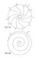
- FIG. 2Aillustrates an embodiment of the present invention wherein a plurality of spiral tracks are written to the disk for use in writing product servo sectors to the disk.
- FIG. 2Billustrates an embodiment of the present invention wherein each spiral track is written over multiple revolutions of the disk.
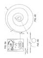
- FIG. 3Ashows an embodiment of the present invention wherein a disk locked clock is synchronized by clocking a modulo-N counter relative to when the sync marks in the spiral tracks are detected.
- FIG. 3Bshows an eye pattern generated by reading the spiral track, including the sync marks in the spiral track.
- FIG. 4illustrates writing of product servo sectors using the disk locked clock to servo on the spiral tracks.
- FIGS. 5A-5Cshow an embodiment of the present invention wherein a sync mark seam is written in a bootstrap spiral track in response to a spindle BEMF voltage.
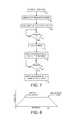
- FIG. 6is a flow diagram according to an embodiment of the present invention wherein the sync mark seam is written by switching sync marks in response to the spindle BEMF voltage.
- FIG. 7is a flow diagram according to an embodiment of the present invention wherein a disk locked clock is synchronized to zero crossings in the spindle BEMF voltage and then used to write the sync mark seam in the bootstrap spiral track.
- FIG. 8shows a velocity profile according to an embodiment of the present invention wherein the bootstrap spiral track is written with a substantially constant velocity until the head contacts a ramp at an outer edge of the disk.
- FIGS. 9A and 9Bshow an embodiment of the present invention wherein the disk locked clock is synchronized to the bootstrap spindle BEMF voltage, and the modulo-N counter initialized in response to detecting the sync mark seam in the bootstrap spiral track.
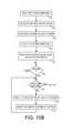
- FIG. 10Ais a flow diagram according to an embodiment of the present invention for initializing the modulo-N counter in response to detecting the sync mark seam in the bootstrap spiral track.
- FIG. 10Bis a flow diagram according to an embodiment of the present invention wherein the modulo-N counter is initialized by shifting it incrementally (e.g., one spindle BEMF zero crossing) in order to maintain stability of the servo loop.
- FIG. 11Ashows an embodiment of the present invention wherein the sync mark seam in the bootstrap spiral track is detected in response to a first and second weighted measure of the read signal corresponding to the first and second sync marks.
- FIG. 11Bis a flow diagram according to an embodiment of the present invention wherein the sync mark seam in the bootstrap spiral is detected when the first and second weighted measures switch amplitude.
- FIG. 12is a flow diagram according to an embodiment of the present invention for calibrating a velocity profile used to write the bootstrap spiral track.
- FIG. 13is a flow diagram according to an embodiment of the present invention for calibrating a gain and offset of a velocity sensor by measuring an estimated state error relative to a reference pattern while seeking the head in both radial directions.
- FIG. 14Aillustrates an embodiment of the present invention wherein the disk locked clock is used to estimate a radial location of the head relative to a rotational angle of the disk while reading the bootstrap spiral track.
- FIG. 14Bis a flow diagram according to an embodiment of the present invention wherein ID and OD circular reference tracks are written on the disk by servoing on the bootstrap spiral track.
- FIG. 15Ashows an embodiment of the present invention wherein a gapped spiral track is written while moving the head in a radial direction opposite of that used to write the bootstrap spiral track.
- FIGS. 15B and 15Cshow a flow diagram according to an embodiment of the present invention wherein the gain and offset of the velocity sensor are adjusted in response to reading the ID and OD circular reference tracks as well as the bootstrap spiral track.
- FIGS. 16A and 16Bshow an embodiment of the present invention wherein the bootstrap spiral track is written at a first slope, and the gapped spiral tracks are written at a second, different slope.
- FIG. 17shows an embodiment of the present invention wherein the estimated state error is measured when crossing the circular reference tracks and the bootstrap spiral track while seeking the head in opposite radial directions.
- FIG. 18Ashows a servo system according to an embodiment of the present invention including a velocity sensor for estimating a velocity of the head based on the BEMF voltage generated by the VCM, as well as a gain/offset adjustment of the velocity sensor based on an estimated state error.
- FIG. 18Bshows a servo system according to an embodiment of the present invention wherein the estimated state error comprises an estimated position error of the head.
- FIG. 2Ashows a disk 18 comprising a plurality of spiral tracks 20 0 - 20 N , wherein each spiral track 20 comprises a high frequency signal 22 interrupted by sync marks 24 ( FIG. 3B ).
- Each spiral track 20 in FIG. 2Aspans a fractional disk revolution; however, in other embodiments each spiral track 20 may span multiple disk revolutions as shown in FIG. 2B .
- the spiral tracks 20 0 - 20 Nare used to servo the head over the disk 18 while writing product servo sectors that define concentric servo tracks such as shown in FIG. 1 .
- the spiral tracks 20 0 - 20 Nwere written using an external spiral track writer or a media writer, and then the control circuitry internal to the disk drive used to process the spiral tracks 20 0 - 20 N in order to self servo write the product servo sectors that define the concentric servo tracks.
- the spiral tracks 20 0 - 20 Nmay be written by the control circuitry internal to each disk drive thereby obviating the bottleneck and expense of an external spiral track writer or media writer.
- FIG. 3Billustrates an “eye” pattern in the read signal generated when the head crosses over a spiral track 20 .
- the read signal representing the spiral track crossingcomprises high frequency transitions 22 interrupted by sync marks 24 at a predetermined interval.
- the eye patternwill shift (left or right) while the sync marks 24 remain fixed (ideally).
- the shift in the eye pattern (detected from the high frequency signal 22 ) relative to the sync marks 24provides the off-track information (spiral position error signal (PES)) for servoing the head.
- PESspiral position error signal
- FIG. 3Ashows an embodiment of the present invention wherein a saw-tooth waveform 26 is generated by clocking a modulo-N counter with a disk locked clock, wherein the frequency of the disk locked clock is adjusted until the sync marks 24 in the spiral tracks 20 0 - 20 N are detected at a target modulo-N count value.
- the disk locked clockmay be generated using any suitable circuitry, such as a phase locked loop (PLL). As each sync mark 24 in the spiral tracks 20 0 - 20 N is detected, the value of the modulo-N counter represents the phase error for adjusting the PLL.
- PLLphase locked loop
- the sync marks 24 in the spiral tracks 20 0 - 20 Nmay comprise any suitable pattern, and in one embodiment, a pattern that is substantially shorter than the sync mark 10 in the conventional product servo sectors 2 of FIG. 1 .
- a shorter sync mark 24allows the spiral tracks 20 0 - 20 N to be written to the disk 18 using a steeper slope (by moving the head faster radially over the disk 18 ) which reduces the time required to write each spiral track 20 0 - 20 N .
- a bootstrap spiral trackmay be written to the disk using different sync marks, wherein the change in sync marks defines a sync mark seam within the bootstrap spiral track.
- the disk locked clockis further synchronized by generating a timing recovery measurement from the high frequency signal 22 between the sync marks 24 in the spiral tracks 20 0 - 20 N . Synchronizing the disk locked clock to the high frequency signal 22 helps maintain proper radial alignment (phase coherency) of the Gray coded track addresses in the product servo sectors.
- the timing recovery measurementmay be generated in any suitable manner.
- the disk locked clockis used to sample the high frequency signal 22 and the signal sample values are processed to generate the timing recovery measurement.
- the timing recovery measurementadjusts the phase of the disk locked clock (PLL) so that the high frequency signal 22 is sampled synchronously. In this manner, the sync marks 24 provide a coarse timing recovery measurement and the high frequency signal 22 provides a fine timing recovery measurement for maintaining synchronization of the disk locked clock.
- PLLphase of the disk locked clock
- FIG. 4illustrates an embodiment of the present invention for writing the product servo sectors 28 0 - 28 N to the disk 18 after synchronizing the disk locked clock in response to at least the sync marks 24 in the spiral tracks 20 0 - 20 N .
- the dashed linesrepresent the centerlines of the servo tracks.
- the sync marks in the spiral tracks 20 0 - 20 Nare written so that there is a shift of two sync marks 24 in the eye pattern ( FIG. 3B ) between servo tracks.
- the sync marks 24 in the spiral tracks 20 0 - 20 Nare written so that there is a shift of N sync marks in the eye pattern between servo tracks.
- each spiral track 20 0 - 20 Nis wider than a servo track, however, in an alternative embodiment the width of each spiral track 20 0 - 20 N is less than or proximate the width of a servo track.
- the spiral PES for maintaining the head along a servo track (tracking) while writing the product servo sectors 28 0 - 28 Nmay be generated from the spiral tracks 20 0 - 20 N in any suitable manner.
- the PESis generated by detecting the eye pattern in FIG. 3B using an envelope detector and detecting a shift in the envelope relative to the sync marks 24 .
- the envelopeis detected by integrating the high frequency signal 22 and detecting a shift in the resulting ramp signal.
- the high frequency signal 22 between the sync marks 24 in the spiral tracksare demodulated as servo bursts and the PES generated by comparing the servo bursts in a similar manner as the servo bursts 14 in the product servo sectors ( FIG. 1 ).
- the product servo sectors 28 0 - 28 Nare written to the disk using the disk locked clock.
- Write circuitryis enabled when the modulo-N counter reaches a predetermined value, wherein the disk locked clock clocks the write circuitry to write the product servo sector 28 to the disk.
- the spiral tracks 20 0 - 20 N on the diskare processed in an interleaved manner to account for the product servo sectors 28 0 - 28 N overwriting a spiral track. For example, when writing the product servo sectors 28 1 to the disk, spiral track 20 1 is processed initially to generate the spiral PES tracking error and the disk locked clock timing recovery measurement. When the product servo sectors 28 1 begin to overwrite spiral track 20 1 , spiral track 20 0 is processed to generate the spiral PES tracking error and the disk locked clock timing recovery measurement.
- FIG. 5Ashows a disk drive according to an embodiment of the present invention comprising a head 30 actuated over a disk 18 , a spindle motor 32 operable to rotate the disk 18 , and control circuitry 34 operable to execute the flow diagram of FIG. 6 .
- a bootstrap spiral track 36is written to the disk 18 ( FIG. 5B ), wherein the bootstrap spiral track 36 comprises a high frequency signal interrupted by sync marks ( FIG. 3B ).
- a spindle back electromotive force (BEMF) voltage generated by the spindle motor 32is measured (step 38 ), a first sync mark is written while writing a first part of the bootstrap spiral track (step 40 ), and a second sync mark is written while writing a second part of the bootstrap spiral track (step 44 ).
- a switch between writing the first sync mark and the second sync markis made (step 42 ) in response to a spindle BEMF voltage, thereby generating a sync mark seam 46 in the bootstrap spiral track.
- FIG. 5Cshows an embodiment of the present invention wherein the control circuitry 34 is operable to switch between writing the first sync mark and the second sync mark in response to zero crossings in the spindle BEMF voltage.
- the sync mark seam 46is written in the bootstrap spiral track 36 at a target interval (e.g., halfway) between two consecutive zero crossings in the spindle BEMF voltage.
- the sync mark seam 46is used to synchronize to the bootstrap spiral track 36 by initializing the modulo-N counter 26 based on the spindle BEMF voltage zero crossing that occurs after detecting the sync mark seam 46 .
- FIG. 7is a flow diagram according to an embodiment of the present invention which extends on the flow diagram of FIG. 6 , wherein the head is positioned at the inner diameter of the disk (step 48 ), for example, by pressing an actuator arm 35 ( FIG. 5B ) against an inner diameter crash stop (not shown).
- the spindle BEMF voltageis measured (step 38 ) and the disk locked clock is synchronized to the zero crossings in the spindle BEMF voltage (step 50 ).
- the control circuitrylaunches the head toward a middle diameter of the disk (step 54 ).
- the bootstrap spiral trackis written using the first sync mark (step 40 ) until the disk locked clock reaches a second value corresponding to the head reaching a target radial location (step 42 ).
- the bootstrap spiral trackis then written using the second sync mark ( 44 ), thereby defining the sync mark seam 46 in the bootstrap spiral track.
- the control circuitryaccelerates the head toward the middle diameter of the disk while writing the first part of the bootstrap spiral track as illustrated by the velocity profile shown in FIG. 8 .
- the control circuitrymoves the head toward the outer diameter of the disk at a substantially constant velocity. That is, the sync mark seam 46 is written in the bootstrap spiral track proximate to the transition between an acceleration segment and a constant velocity segment as illustrated in FIG. 8 .
- the diskafter launching the head toward the middle diameter of the disk when writing the bootstrap spiral track, the disk will rotate through a known angle before writing the sync mark seam 46 , wherein the known angle corresponds to a number of cycles of the disk locked clock. Accordingly, in one embodiment the head is launched when the disk locked clock reaches a first value that is computed relative to a number of cycles before writing the sync mark seam:
- first_valuecountsPerRev - 1 2 ⁇ countsPerRev spindleZXPerRev - second_value where countsPerRev represents the total number of cycles (counts) of the disk locked clock over a full revolution of the disk, spindleZXPerRev represents the number of spindle BEMF zero crossings per revolution of the disk, and the second value represents the disk rotation angle from the launch point until the sync mark seam is written.
- Launching the head when the disk locked clock reaches the first value computed from the above equationwill cause the sync mark seam 46 to be written at an interval that is halfway between two consecutive spindle BEMF zero crossings as illustrated in FIG. 5C .
- the sync mark seam 46 in the bootstrap spiral trackis used to resynchronize the disk locked clock, for example, after a power cycle. Synchronizing the disk locked clock to the sync mark seam 46 essentially initializes the radial and circumferential location of the head to a known state. In addition, after synchronizing the disk locked clock to the sync mark seam 46 the head may be accurately servoed radially over the disk based on the bootstrap spiral track relative to the rotational angle of the disk as determined by the disk locked clock.
- FIGS. 9A and 9Billustrate an embodiment of the present invention for resynchronizing the disk locked clock to the sync mark seam 46 as is understood with reference to the flow diagram of FIG. 10A .
- the headis positioned over the disk (step 56 ), for example, by loading the head off a ramp 57 ( FIG. 5B ).
- the spindle BEMF voltageis measured (step 58 ) and the disk locked clock synchronized to the zero crossings in the spindle BEMF voltage (step 60 ).
- the disk locked clockis used to clock the modulo-N counter 26 (step 62 ) such that the counter wraps at an arbitrary zero crossing 63 ( FIG. 9A ).
- the headis then moved radially over the disk in order to search for the sync mark seam (step 64 ).
- the modulo-N counteris initialized (step 68 ). For example, in one embodiment the modulo-N counter is initialized so it wraps at the spindle BEMF zero crossing 65 that follows the detection of the sync mark seam as illustrated in FIG. 9B .
- FIG. 10Bshows a flow diagram according to an embodiment of the present invention which extends on the flow diagram of FIG. 10A , wherein the modulo-N counter is adjusted incrementally by a spindle BEMF zero crossing so as to maintain stability in the servo loop.
- the modulo-N counteris shifted by an amount corresponding to a single spindle BEMF zero crossing (step 72 ).
- the shift in the modulo-N counterinduces a transient in the servo loop similar to a radially shift of the head.
- the servo systemis allowed to settle to account for the transient (step 74 ).
- the processis then repeated starting at step 70 until the modulo-N counter wraps at the target spindle BEMF zero crossing.
- the processis repeated twice in order to shift the modulo-N counter by two spindle BEMF zero crossings so that the modulo-N counter wraps at zero crossing 65 .
- the sync mark seam 46may be detected using first and second correlators matched to the first and second sync marks.
- the sync mark seam 46may be detected when there is a switch between the output of the correlators.
- noise in the read signalmay reduce the accuracy of the correlators leading to a false detection of the sync mark seam 46 .
- FIGS. 11A and 11Bshow an embodiment of the present invention for detecting a sync mark seam in a spiral track more reliably.
- the control circuitrymoves the head radially over the disk (step 76 ) and reads the spiral track to generate a read signal (step 78 ).
- the read signal representing the high frequency signal 22( FIG. 3B ) is integrated (step 80 ), and when the first sync mark is detected (step 82 ), the integrated read signal is accumulated into a first weighted measure (step 84 ).
- the integrated read signalis accumulated into a second weighted measure (step 86 ).
- the sync mark seam in the spiral trackis detected in response to the first and second weighted measures (step 88 ).
- the sync mark seamis detected proximate to when an amplitude of the second weighted measure crosses an amplitude of the first weighted measure as illustrated in FIG. 11A .
- Weighting the sync mark detection relative to the amplitude of the read signalimproves the accuracy in detecting the sync mark seam by reducing the significance of the sync marks near the edge of the spiral track crossing where the signal-to-noise ratio is less ( FIG. 3B ).
- the control circuitrycalibrates a velocity profile prior to writing the bootstrap spiral track 36 to the disk ( FIG. 5B ), wherein the velocity profile (e.g., FIG. 8 ) corresponds to a desired slope for the spiral track across the radius of the disk.
- FIG. 12is a flow diagram illustrating an embodiment for calibrating the velocity profile wherein the head is positioned at an inner diameter of the disk (step 90 ) and then moved toward the ramp in response to the velocity profile (step 92 ). An interval is measured (step 94 ) from a beginning of the movement until the head begins unloading onto the ramp 57 of FIG. 5B (step 96 ). The velocity profile is then adjusted in response to the measured interval (step 98 ). For example, the velocity profile is adjusted based on the difference between the measured interval and a target interval.
- the interval at step 94is measured relative to the disk locked clock which represents the rotational phase of the disk.
- the target intervalcorresponds to a target rotational phase of the disk (which may be less or more than one revolution).
- the velocity profileis adjusted and the flow diagram of FIG. 12 repeated until the measured interval substantially matches the target interval.
- FIG. 8shows an example velocity profile comprising an acceleration segment for accelerating the head away from the inner diameter of the disk, and a constant velocity segment for moving the head at a substantially constant velocity until the head begins unloading onto the ramp.
- the constant velocity of the head as it contacts the rampis consistent with the constant velocity employed when unloading the head onto the ramp during a normal unload operation.
- the bootstrap spiral track 36is written to the disk using the calibrated velocity profile.
- the headwhen writing the bootstrap spiral track 36 the head is accelerated away from the inner diameter of the disk and then moved at a substantially constant velocity until the head contacts the ramp 57 . After the head contacts the ramp, the head is decelerated until it reaches the parked position on the ramp 57 .
- the resulting bootstrap spiral track 36comprises an increasing slope while the head accelerates away from the inner diameter of the disk and a substantially constant slope until the head contacts the ramp as illustrated in FIG. 16A .
- the substantially constant slope of the bootstrap spiral track 36 up to the ramp 57helps maximize the usable area of the disk for writing the product servo sectors by enabling an outer diameter circular reference track to be written very near the outer edge of the disk as described below.
- FIG. 13is a flow diagram according to an embodiment of the present invention wherein the disk drive in this embodiment comprises a voice coil motor (VCM) 33 for rotating an actuator arm 35 about a pivot ( FIG. 5A ) in order to move the head radially over the disk.
- VCMvoice coil motor
- At least one reference trackis written on the disk (step 100 ), and the head is positioned near a first diameter of the disk (step 101 ). While moving the head from the first diameter toward a second diameter of the disk (step 102 ), the reference track is read (step 103 ) and a first estimated state error is measured (step 104 ).
- VCMvoice coil motor
- the reference trackis read (step 106 ) and a second estimated state error is measured (step 107 ).
- a gain and an offset of a velocity sensorare adjusted in response to the first and second estimated state errors (step 108 ), wherein the velocity sensor estimates a velocity of the head in response to a BEMF voltage generated by the VCM 33 .
- the reference track written at step 100 of FIG. 13may comprise any suitable pattern.
- the reference trackcomprises at least one circular reference track, wherein in an embodiment described below, the reference track comprises a circular reference track written near the inner diameter of the disk and a circular reference track written near an outer diameter of the disk.
- the reference trackmay comprise the bootstrap spiral track 36 , and in yet another embodiment, the reference track may comprise both a circular reference track and a spiral reference track.
- FIG. 14Aillustrates an embodiment of the present invention wherein after writing the bootstrap spiral track 36 , the control circuitry servos on the bootstrap spiral track 36 to write at least one circular reference track (e.g., 112 A) on the disk 18 .
- the gain and offset of the velocity sensoris then adjusted in response to the circular reference track 112 A.
- FIG. 14Bis a flow diagram according to the embodiment of the present invention which is understood with reference to FIG. 14A .
- the control circuitrypositions the head at an inner diameter of the disk (step 115 ), such as by pressing the actuator arm against the inner diameter crash stop.
- the disk locked clockis then synchronized to the bootstrap spiral track (step 116 ), wherein in one embodiment the disk locked clock is first synchronized to the zero crossings of the spindle BEMF voltage as described above.
- the headis then moved radially while searching for the sync mark seam (step 118 ), and when the sync mark seam is located, the modulo-N counter is initialized as described above.
- the control circuitryis able to servo the head to any desired radial location by servoing on the bootstrap spiral track 36 relative to the modulo-N counter as described above.
- the control circuitrypositions the head near the inner diameter of the disk and writes a circular reference track 112 A ( FIG. 14A ) while servoing on the bootstrap spiral track (step 120 ).
- the inner diameter circular reference track 112 Ais written proximate the sync mark seam 46 , which in one embodiment corresponds to the end of the constant velocity segment of the velocity profile used to write a plurality of spiral tracks to the disk. Accordingly, in this embodiment after writing one of the spiral tracks the inner diameter reference track 112 A is read in order to measure an estimated state error for adjusting the gain and offset of the velocity sensor.
- the control circuitryseeks the head to an outer diameter location proximate the ramp (step 122 ) in order to write an outer diameter circular reference track 112 B as shown in FIG. 14A .
- the control circuitryestimates the radial location of the ramp 57 in FIG. 14A by evaluating the rotational phase of the disk (as determined from the disk locked clock) relative to the spiral bootstrap spiral track 36 . That is, when writing the bootstrap spiral track 36 to the disk, the rotational phase of the disk (disk locked clock) is saved when the head contacts the ramp 57 .
- the control circuitrythen positions the head at the outer diameter of the disk by servoing the head on the bootstrap spiral track until the rotational phase ⁇ of the disk corresponds to the location of the ramp (minus a back-off delta) as illustrated in FIG. 14A , and then writes the outer diameter circular reference track 112 B (step 124 ).
- the inner diameter and outer diameter circular reference tracks 112 A and 112 Bare then used to adjust the gain and offset of the velocity sensor while writing a plurality of spiral tracks to the disk (step 126 ).
- the outer diameter circular reference track 112 Bis written at the edge of the constant velocity segment of the velocity profile used to write the spiral tracks. As the head crosses over and reads the circular reference tracks at both the inner and outer diameter, an estimated state error is generated for adjusting the gain and offset of the velocity sensor.
- FIG. 15Ashows an embodiment of the present invention for writing the plurality of spiral tracks while adjusting the gain and offset of the velocity sensor in response to the circular reference tracks.
- the bootstrap spiral track 36is also used to adjust the gain and offset of the velocity sensor by measuring an estimated state error each time the head crosses the bootstrap spiral track 36 . Accordingly in this embodiment, the writing of each spiral track is paused in order to read the bootstrap spiral track 36 as the head approaches an expected bootstrap spiral track crossing, and therefore the spiral tracks are written with gaps to allow the head to read the bootstrap spiral track 36 .
- the control circuitrypositions the head at a first radial location (inner diameter in this example), and moves the head from the first radial location toward a second radial location (outer diameter) while writing the bootstrap spiral track 36 to the disk 18 .
- the headis then positioned near the second radial location (outer diameter), and moved from the second radial location toward the first radial location (inner diameter) while writing a gapped spiral track 114 to the disk 18 .
- the gapped spiral track 114is written in the opposite radial direction that the bootstrap spiral track 36 is written. Writing the gapped spiral track 114 in the opposite direction increases the number of bootstrap spiral crossings and therefore the number of samples used to adjust the gain and offset of the velocity sensor.
- FIGS. 15B and 15Cshow a flow diagram according to a more detailed embodiment of the present invention, wherein the control circuitry seeks the head to the outer diameter of the disk (step 128 ), and then begins a new seek operation in the opposite direction toward the outer diameter circular reference track (step 130 ). When the outer diameter circular reference track is detected (step 132 ) an estimated state error is measured (step 134 ). The control circuitry then begins writing a gapped spiral track to the disk (step 136 ) while seeking the head radially over the disk at the substantially constant velocity of the velocity profile. When the head approaches the bootstrap spiral track 36 as shown in FIG.
- step 138the writing of the gapped spiral track is paused (step 140 ) in order to read the bootstrap spiral track and measure an estimated state error (step 142 ).
- the gapped spiral trackcontinues to be written across the radius of the disk (step 144 ) while periodically pausing to read the bootstrap spiral track 36 and generate another estimated state error.
- the control circuitrystops writing the gapped spiral track (step 148 ), and reads the inner diameter circular reference track in order to measure an estimated state error (step 150 ).
- the control circuitrythen reverses direction of the head and begins seeking the head toward the inner diameter circular reference track (step 152 of FIG. 15C ).
- an estimated state erroris measured (step 156 ).
- the bootstrap spiral trackis read in order to measure an estimated state error (step 160 ).
- the headcontinues to seek across the radius of the disk while periodically reading the bootstrap spiral track 36 to generate another estimated state error.
- the control circuitryreads the outer diameter circular reference track in order to measure an estimated state error (step 164 ).
- the control circuitrythen adjusts the gain and offset of the velocity sensor using the estimated state errors (step 166 ) prior to repeating the flow diagram (starting at step 130 of FIG. 15B ) in order to write another gapped spiral track.
- the control circuitrywrites the bootstrap spiral track 36 having a first substantially constant slope, and writes the gapped spiral tracks having a second substantially constant slope different than the first substantially constant slope.
- FIG. 16Awherein the slope of the gapped spiral tracks is greater than the slope of the bootstrap spiral track, or in an alternative embodiment shown in FIG. 16B , the slope of the gapped spiral tracks may be less than the slope of the bootstrap spiral track.
- FIGS. 16A and 16Balso illustrate an embodiment wherein the bootstrap spiral track is written with a substantially constant slope until the head contacts the ramp, whereas the gapped spiral tracks are written with a substantially constant slope until the head reaches the inner diameter circular reference track. Also in the embodiment of FIGS. 16A and 16B the gapped spiral tracks begin when the head reaches the constant velocity segment of the velocity profile (e.g., when the head reaches the outer diameter circular reference track).
- the control circuitryseeks the head back to the outer diameter of the disk (step 152 ) using the same velocity profile used to write the gapped spiral tracks. Since the velocity profile for writing the gapped spiral tracks is different than that used to write the bootstrap spiral track, the head will cross the bootstrap spiral track while seeking back to the outer diameter of the disk. In this manner, each time the head crosses the bootstrap spiral track while seeking back to the outer diameter of the disk, an estimated state error is measured as described above.
- the headWhen seeking the head back to the outer diameter of the disk, the head seeks in the same direction as when writing the bootstrap spiral track. Therefore, in one embodiment there are fewer bootstrap spiral track crossings (and fewer estimated state errors) when seeking the head back to the outer diameter of the disk as compared to the number of bootstrap spiral track crossings when seeking the head toward the inner diameter of the disk while writing a gapped spiral track.
- FIG. 17shows multiple seeks from the OD to ID and ID to OD and the corresponding reference track crossings (circular reference track and bootstrap spiral track).
- a polarity of the estimated state errorswill change depending on the radial seek direction of the head as well as a polarity of the gain error and the offset error.
- a negative gain errori.e., the gain of the velocity sensor is too high.
- Thiswill cause the estimated state error to be a first polarity (e.g., positive) when seeking toward the ID of the disk and an opposite polarity (e.g., negative) when seeking toward the OD of the disk.
- the polaritieswill reverse if the gain error is positive (i.e., the gain of the velocity sensor is too low).
- a gain erroris generated by computing a difference between a first estimated state error generated while seeking in a first direction (e.g., toward the ID) and a second estimated state error generated while seeking in an opposite direction (e.g., toward the OD), and an offset error is generated by computing a sum of the first and second estimated state errors.
- the first estimated state errormay be measured when crossing the ID circular reference track 112 A while seeking toward the ID
- the first estimated state error(e.g., idStateErr) may be generated by summing the estimated state errors measured while seeking in the first direction (e.g., toward the ID), and the second estimated state error (e.g., odStateErr) may be generated by summing the estimated state errors measured while seeking in the opposite direction (e.g., toward the OD).
- the resulting gain error and offset errormay be filtered using any suitable compensation filtering (e.g., averaging) in order to generate a gain adjustment and an offset adjustment used to adjust the velocity sensor.
- FIG. 18Ashows a servo system according to an embodiment of the present invention including a velocity sensor 168 for estimating a velocity 170 of the head based on the BEMF voltage 172 generated by the VCM 33 .
- the velocity sensor 168comprises an R+L compensation block 174 that generates a compensation voltage 176 representing a voltage contribution to the BEMF voltage 172 due to the resistance and inductance of the VCM 33 .
- the compensation voltage 176is subtracted from the BEMF voltage 172 to generate a compensated voltage 178 representing the velocity component of the BEMF voltage 172 .
- the compensated voltage 178is converted 180 to a digital signal 182 , and the digital signal 182 is scaled by a scalar 184 that determines the gain of the velocity sensor 168 .
- An offset value 186is then subtracted from the scaled compensated voltage 188 to generate the output signal 170 representing the estimated velocity of the head.
- a control error generator 190generates an error signal 192 representing a difference between an estimated state based on the estimated velocity 170 and a reference value generated by a reference generator 194 (e.g., generated in response to a velocity profile).
- the error signal 192is processed by a servo compensator 196 that generates a digital control signal 198 converted 200 to an analog control signal 202 applied to the VCM 33 in order to adjust the velocity of the VCM 33 so as to reduce the error signal 192 .
- a state error generator 204generates an estimated state error 206 representing a difference between a measured state 208 and an estimated state based on the estimated velocity 170 .
- the measured state 208is generated at each reference track crossing (circular reference track or bootstrap spiral).
- the estimated state error 206is processed by a gain/offset adjustment block 210 as described above in order to adjust the gain of the velocity sensor 168 by adjusting the scalar 184 , and to adjust the offset of the velocity sensor 168 by adjusting the offset value 186 .
- FIG. 18Bshows an embodiment of the servo system wherein the reference value 194 is a reference position, the error signal 192 is a position error signal, and the estimated state error 206 is an estimated position error.
- An estimated position 212may be generated by integrating 214 the estimated velocity 170 output by the velocity sensor 168 .
- a windowis opened to begin searching for the reference track crossing (as detected from the read signal).
- the difference between the estimated position 214 of the head and the measured position 208 of the head when the reference track is crossedrepresents the estimated position error 206 used to adjust the gain and offset of the velocity sensor 168 .
- control circuitrymay be implemented within a read channel integrated circuit, or in a component separate from the read channel, such as a disk controller, or certain steps described above may be performed by a read channel and others by a disk controller.
- the read channel and disk controllerare implemented as separate integrated circuits, and in an alternative embodiment they are fabricated into a single integrated circuit or system on a chip (SOC).
- the control circuitrymay include a suitable preamp circuit implemented as a separate integrated circuit, integrated into the read channel or disk controller circuit, or integrated into an SOC.
- control circuitrycomprises a microprocessor executing instructions, the instructions being operable to cause the microprocessor to perform the steps of the flow diagrams described herein.
- the instructionsmay be stored in any computer-readable medium. In one embodiment, they may be stored on a non-volatile semiconductor memory external to the microprocessor, or integrated with the microprocessor in a SOC. In another embodiment, the instructions are stored on the disk and read into a volatile semiconductor memory when the disk drive is powered on. In yet another embodiment, the control circuitry comprises suitable logic circuitry, such as state machine circuitry.
Landscapes
- Moving Of The Head To Find And Align With The Track (AREA)
Abstract
Description
where countsPerRev represents the total number of cycles (counts) of the disk locked clock over a full revolution of the disk, spindleZXPerRev represents the number of spindle BEMF zero crossings per revolution of the disk, and the second value represents the disk rotation angle from the launch point until the sync mark seam is written. Launching the head when the disk locked clock reaches the first value computed from the above equation will cause the
Gain Error=idStateErr−odStateErr
Offset Error=idStateErr+odStateErr.
In the embodiment wherein an estimated state error is measured at each bootstrap spiral track crossing as well as each circular reference track crossing (
Claims (18)
Priority Applications (1)
| Application Number | Priority Date | Filing Date | Title |
|---|---|---|---|
| US13/334,955US8665551B1 (en) | 2011-12-22 | 2011-12-22 | Disk drive adjusting gain and offset of BEMF velocity sensor during self writing of spiral tracks |
Applications Claiming Priority (1)
| Application Number | Priority Date | Filing Date | Title |
|---|---|---|---|
| US13/334,955US8665551B1 (en) | 2011-12-22 | 2011-12-22 | Disk drive adjusting gain and offset of BEMF velocity sensor during self writing of spiral tracks |
Publications (1)
| Publication Number | Publication Date |
|---|---|
| US8665551B1true US8665551B1 (en) | 2014-03-04 |
Family
ID=50158787
Family Applications (1)
| Application Number | Title | Priority Date | Filing Date |
|---|---|---|---|
| US13/334,955Expired - Fee RelatedUS8665551B1 (en) | 2011-12-22 | 2011-12-22 | Disk drive adjusting gain and offset of BEMF velocity sensor during self writing of spiral tracks |
Country Status (1)
| Country | Link |
|---|---|
| US (1) | US8665551B1 (en) |
Cited By (103)
| Publication number | Priority date | Publication date | Assignee | Title |
|---|---|---|---|---|
| US8824081B1 (en) | 2012-03-13 | 2014-09-02 | Western Digital Technologies, Inc. | Disk drive employing radially coherent reference pattern for servo burst demodulation and fly height measurement |
| US8830617B1 (en) | 2013-05-30 | 2014-09-09 | Western Digital Technologies, Inc. | Disk drive adjusting state estimator to compensate for unreliable servo data |
| US8879191B1 (en) | 2012-11-14 | 2014-11-04 | Western Digital Technologies, Inc. | Disk drive modifying rotational position optimization algorithm to achieve target performance for limited stroke |
| US8891191B1 (en) | 2014-05-06 | 2014-11-18 | Western Digital Technologies, Inc. | Data storage device initializing read signal gain to detect servo seed pattern |
| US8891194B1 (en) | 2013-05-14 | 2014-11-18 | Western Digital Technologies, Inc. | Disk drive iteratively adapting correction value that compensates for non-linearity of head |
| US8896957B1 (en) | 2013-05-10 | 2014-11-25 | Western Digital Technologies, Inc. | Disk drive performing spiral scan of disk surface to detect residual data |
| US8902539B1 (en) | 2014-05-13 | 2014-12-02 | Western Digital Technologies, Inc. | Data storage device reducing seek power consumption |
| US8902538B1 (en) | 2013-03-29 | 2014-12-02 | Western Digital Technologies, Inc. | Disk drive detecting crack in microactuator |
| US8913342B1 (en) | 2014-03-21 | 2014-12-16 | Western Digital Technologies, Inc. | Data storage device adjusting range of microactuator digital-to-analog converter based on operating temperature |
| US8917475B1 (en) | 2013-12-20 | 2014-12-23 | Western Digital Technologies, Inc. | Disk drive generating a disk locked clock using radial dependent timing feed-forward compensation |
| US8917474B1 (en) | 2011-08-08 | 2014-12-23 | Western Digital Technologies, Inc. | Disk drive calibrating a velocity profile prior to writing a spiral track |
| US8922940B1 (en) | 2014-05-27 | 2014-12-30 | Western Digital Technologies, Inc. | Data storage device reducing spindle motor voltage boost during power failure |
| US8922931B1 (en) | 2013-05-13 | 2014-12-30 | Western Digital Technologies, Inc. | Disk drive releasing variable amount of buffered write data based on sliding window of predicted servo quality |
| US8922937B1 (en) | 2012-04-19 | 2014-12-30 | Western Digital Technologies, Inc. | Disk drive evaluating multiple vibration sensor outputs to enable write-protection |
| US8922938B1 (en) | 2012-11-02 | 2014-12-30 | Western Digital Technologies, Inc. | Disk drive filtering disturbance signal and error signal for adaptive feed-forward compensation |
| US8929021B1 (en) | 2012-03-27 | 2015-01-06 | Western Digital Technologies, Inc. | Disk drive servo writing from spiral tracks using radial dependent timing feed-forward compensation |
| US8929022B1 (en) | 2012-12-19 | 2015-01-06 | Western Digital Technologies, Inc. | Disk drive detecting microactuator degradation by evaluating frequency component of servo signal |
| US8934186B1 (en) | 2014-03-26 | 2015-01-13 | Western Digital Technologies, Inc. | Data storage device estimating servo zone to reduce size of track address |
| US8937784B1 (en) | 2012-08-01 | 2015-01-20 | Western Digital Technologies, Inc. | Disk drive employing feed-forward compensation and phase shift compensation during seek settling |
| US8941939B1 (en) | 2013-10-24 | 2015-01-27 | Western Digital Technologies, Inc. | Disk drive using VCM BEMF feed-forward compensation to write servo data to a disk |
| US8941945B1 (en) | 2014-06-06 | 2015-01-27 | Western Digital Technologies, Inc. | Data storage device servoing heads based on virtual servo tracks |
| US8947819B1 (en) | 2012-08-28 | 2015-02-03 | Western Digital Technologies, Inc. | Disk drive implementing hysteresis for primary shock detector based on a more sensitive secondary shock detector |
| US8953278B1 (en) | 2011-11-16 | 2015-02-10 | Western Digital Technologies, Inc. | Disk drive selecting disturbance signal for feed-forward compensation |
| US8953271B1 (en) | 2013-05-13 | 2015-02-10 | Western Digital Technologies, Inc. | Disk drive compensating for repeatable run out selectively per zone |
| US8958169B1 (en) | 2014-06-11 | 2015-02-17 | Western Digital Technologies, Inc. | Data storage device re-qualifying state estimator while decelerating head |
| US8970979B1 (en) | 2013-12-18 | 2015-03-03 | Western Digital Technologies, Inc. | Disk drive determining frequency response of actuator near servo sample frequency |
| US8982501B1 (en) | 2014-09-22 | 2015-03-17 | Western Digital Technologies, Inc. | Data storage device compensating for repeatable disturbance when commutating a spindle motor |
| US8982490B1 (en) | 2014-04-24 | 2015-03-17 | Western Digital Technologies, Inc. | Data storage device reading first spiral track while simultaneously writing second spiral track |
| US8995082B1 (en) | 2011-06-03 | 2015-03-31 | Western Digital Technologies, Inc. | Reducing acoustic noise in a disk drive when exiting idle mode |
| US8995075B1 (en) | 2012-06-21 | 2015-03-31 | Western Digital Technologies, Inc. | Disk drive adjusting estimated servo state to compensate for transient when crossing a servo zone boundary |
| US9001454B1 (en) | 2013-04-12 | 2015-04-07 | Western Digital Technologies, Inc. | Disk drive adjusting phase of adaptive feed-forward controller when reconfiguring servo loop |
| US9007714B1 (en) | 2014-07-18 | 2015-04-14 | Western Digital Technologies Inc. | Data storage device comprising slew rate anti-windup compensation for microactuator |
| US9013824B1 (en) | 2014-06-04 | 2015-04-21 | Western Digital Technologies, Inc. | Data storage device comprising dual read sensors and dual servo channels to improve servo demodulation |
| US9013825B1 (en) | 2014-03-24 | 2015-04-21 | Western Digital Technologies, Inc. | Electronic system with vibration management mechanism and method of operation thereof |
| US9026728B1 (en) | 2013-06-06 | 2015-05-05 | Western Digital Technologies, Inc. | Disk drive applying feed-forward compensation when writing consecutive data tracks |
| US9025269B1 (en) | 2014-01-02 | 2015-05-05 | Western Digital Technologies, Inc. | Disk drive compensating for cycle slip of disk locked clock when reading mini-wedge |
| US9047919B1 (en) | 2013-03-12 | 2015-06-02 | Western Digitial Technologies, Inc. | Disk drive initializing servo read channel by reading data preceding servo preamble during access operation |
| US9047932B1 (en) | 2014-03-21 | 2015-06-02 | Western Digital Technologies, Inc. | Data storage device adjusting a power loss threshold based on samples of supply voltage |
| US9047901B1 (en) | 2013-05-28 | 2015-06-02 | Western Digital Technologies, Inc. | Disk drive measuring spiral track error by measuring a slope of a spiral track across a disk radius |
| US9053727B1 (en) | 2014-06-02 | 2015-06-09 | Western Digital Technologies, Inc. | Disk drive opening spiral crossing window based on DC and AC spiral track error |
| US9053726B1 (en) | 2014-01-29 | 2015-06-09 | Western Digital Technologies, Inc. | Data storage device on-line adapting disturbance observer filter |
| US9053712B1 (en) | 2014-05-07 | 2015-06-09 | Western Digital Technologies, Inc. | Data storage device reading servo sector while writing data sector |
| US9058834B1 (en) | 2013-11-08 | 2015-06-16 | Western Digital Technologies, Inc. | Power architecture for low power modes in storage devices |
| US9058827B1 (en) | 2013-06-25 | 2015-06-16 | Western Digitial Technologies, Inc. | Disk drive optimizing filters based on sensor signal and disturbance signal for adaptive feed-forward compensation |
| US9058826B1 (en) | 2014-02-13 | 2015-06-16 | Western Digital Technologies, Inc. | Data storage device detecting free fall condition from disk speed variations |
| US9064537B1 (en) | 2013-09-13 | 2015-06-23 | Western Digital Technologies, Inc. | Disk drive measuring radial offset between heads by detecting a difference between ramp contact |
| US9076473B1 (en) | 2014-08-12 | 2015-07-07 | Western Digital Technologies, Inc. | Data storage device detecting fly height instability of head during load operation based on microactuator response |
| US9076490B1 (en) | 2012-12-12 | 2015-07-07 | Western Digital Technologies, Inc. | Disk drive writing radial offset spiral servo tracks by reading spiral seed tracks |
| US9076471B1 (en) | 2013-07-31 | 2015-07-07 | Western Digital Technologies, Inc. | Fall detection scheme using FFS |
| US9076472B1 (en) | 2014-08-21 | 2015-07-07 | Western Digital (Fremont), Llc | Apparatus enabling writing servo data when disk reaches target rotation speed |
| US9093105B2 (en) | 2011-12-09 | 2015-07-28 | Western Digital Technologies, Inc. | Disk drive charging capacitor using motor supply voltage during power failure |
| US9099147B1 (en) | 2014-09-22 | 2015-08-04 | Western Digital Technologies, Inc. | Data storage device commutating a spindle motor using closed-loop rotation phase alignment |
| US9111575B1 (en) | 2014-10-23 | 2015-08-18 | Western Digital Technologies, Inc. | Data storage device employing adaptive feed-forward control in timing loop to compensate for vibration |
| US9129630B1 (en) | 2014-12-16 | 2015-09-08 | Western Digital Technologies, Inc. | Data storage device employing full servo sectors on first disk surface and mini servo sectors on second disk surface |
| US9142235B1 (en) | 2009-10-27 | 2015-09-22 | Western Digital Technologies, Inc. | Disk drive characterizing microactuator by injecting sinusoidal disturbance and evaluating feed-forward compensation values |
| US9141177B1 (en) | 2014-03-21 | 2015-09-22 | Western Digital Technologies, Inc. | Data storage device employing glitch compensation for power loss detection |
| US9142249B1 (en) | 2013-12-06 | 2015-09-22 | Western Digital Technologies, Inc. | Disk drive using timing loop control signal for vibration compensation in servo loop |
| US9142225B1 (en) | 2014-03-21 | 2015-09-22 | Western Digital Technologies, Inc. | Electronic system with actuator control mechanism and method of operation thereof |
| US9147428B1 (en) | 2013-04-24 | 2015-09-29 | Western Digital Technologies, Inc. | Disk drive with improved spin-up control |
| US9147418B1 (en) | 2013-06-20 | 2015-09-29 | Western Digital Technologies, Inc. | Disk drive compensating for microactuator gain variations |
| US9153283B1 (en) | 2014-09-30 | 2015-10-06 | Western Digital Technologies, Inc. | Data storage device compensating for hysteretic response of microactuator |
| US9165583B1 (en) | 2014-10-29 | 2015-10-20 | Western Digital Technologies, Inc. | Data storage device adjusting seek profile based on seek length when ending track is near ramp |
| US9171567B1 (en) | 2014-05-27 | 2015-10-27 | Western Digital Technologies, Inc. | Data storage device employing sliding mode control of spindle motor |
| US9171568B1 (en) | 2014-06-25 | 2015-10-27 | Western Digital Technologies, Inc. | Data storage device periodically re-initializing spindle motor commutation sequence based on timing data |
| US9208808B1 (en) | 2014-04-22 | 2015-12-08 | Western Digital Technologies, Inc. | Electronic system with unload management mechanism and method of operation thereof |
| US9208810B1 (en) | 2014-04-24 | 2015-12-08 | Western Digital Technologies, Inc. | Data storage device attenuating interference from first spiral track when reading second spiral track |
| US9208815B1 (en) | 2014-10-09 | 2015-12-08 | Western Digital Technologies, Inc. | Data storage device dynamically reducing coast velocity during seek to reduce power consumption |
| US9214175B1 (en) | 2015-03-16 | 2015-12-15 | Western Digital Technologies, Inc. | Data storage device configuring a gain of a servo control system for actuating a head over a disk |
| US9230592B1 (en) | 2014-12-23 | 2016-01-05 | Western Digital Technologies, Inc. | Electronic system with a method of motor spindle bandwidth estimation and calibration thereof |
| US9230593B1 (en) | 2014-12-23 | 2016-01-05 | Western Digital Technologies, Inc. | Data storage device optimizing spindle motor power when transitioning into a power failure mode |
| US9245560B1 (en) | 2015-03-09 | 2016-01-26 | Western Digital Technologies, Inc. | Data storage device measuring reader/writer offset by reading spiral track and concentric servo sectors |
| US9245540B1 (en) | 2014-10-29 | 2016-01-26 | Western Digital Technologies, Inc. | Voice coil motor temperature sensing circuit to reduce catastrophic failure due to voice coil motor coil shorting to ground |
| US9245577B1 (en) | 2015-03-26 | 2016-01-26 | Western Digital Technologies, Inc. | Data storage device comprising spindle motor current sensing with supply voltage noise attenuation |
| US9251823B1 (en) | 2014-12-10 | 2016-02-02 | Western Digital Technologies, Inc. | Data storage device delaying seek operation to avoid thermal asperities |
| US9269386B1 (en) | 2014-01-29 | 2016-02-23 | Western Digital Technologies, Inc. | Data storage device on-line adapting disturbance observer filter |
| US9286927B1 (en) | 2014-12-16 | 2016-03-15 | Western Digital Technologies, Inc. | Data storage device demodulating servo burst by computing slope of intermediate integration points |
| US9286925B1 (en) | 2015-03-26 | 2016-03-15 | Western Digital Technologies, Inc. | Data storage device writing multiple burst correction values at the same radial location |
| US9343102B1 (en) | 2015-03-25 | 2016-05-17 | Western Digital Technologies, Inc. | Data storage device employing a phase offset to generate power from a spindle motor during a power failure |
| US9343094B1 (en) | 2015-03-26 | 2016-05-17 | Western Digital Technologies, Inc. | Data storage device filtering burst correction values before downsampling the burst correction values |
| US9350278B1 (en) | 2014-06-13 | 2016-05-24 | Western Digital Technologies, Inc. | Circuit technique to integrate voice coil motor support elements |
| US9349401B1 (en) | 2014-07-24 | 2016-05-24 | Western Digital Technologies, Inc. | Electronic system with media scan mechanism and method of operation thereof |
| US9355676B1 (en) | 2015-03-25 | 2016-05-31 | Western Digital Technologies, Inc. | Data storage device controlling amplitude and phase of driving voltage to generate power from a spindle motor |
| US9355667B1 (en) | 2014-11-11 | 2016-05-31 | Western Digital Technologies, Inc. | Data storage device saving absolute position at each servo wedge for previous write operations |
| US9361939B1 (en) | 2014-03-10 | 2016-06-07 | Western Digital Technologies, Inc. | Data storage device characterizing geometry of magnetic transitions |
| US9396751B1 (en) | 2015-06-26 | 2016-07-19 | Western Digital Technologies, Inc. | Data storage device compensating for fabrication tolerances when measuring spindle motor current |
| US9407015B1 (en) | 2014-12-29 | 2016-08-02 | Western Digital Technologies, Inc. | Automatic power disconnect device |
| US9418689B2 (en) | 2014-10-09 | 2016-08-16 | Western Digital Technologies, Inc. | Data storage device generating an operating seek time profile as a function of a base seek time profile |
| US9424871B1 (en) | 2012-09-13 | 2016-08-23 | Western Digital Technologies, Inc. | Disk drive correcting an error in a detected gray code |
| US9424868B1 (en) | 2015-05-12 | 2016-08-23 | Western Digital Technologies, Inc. | Data storage device employing spindle motor driving profile during seek to improve power performance |
| US9437231B1 (en) | 2015-09-25 | 2016-09-06 | Western Digital Technologies, Inc. | Data storage device concurrently controlling and sensing a secondary actuator for actuating a head over a disk |
| US9437237B1 (en) | 2015-02-20 | 2016-09-06 | Western Digital Technologies, Inc. | Method to detect power loss through data storage device spindle speed |
| US9454212B1 (en) | 2014-12-08 | 2016-09-27 | Western Digital Technologies, Inc. | Wakeup detector |
| US9471072B1 (en) | 2013-11-14 | 2016-10-18 | Western Digital Technologies, Inc | Self-adaptive voltage scaling |
| US9484733B1 (en) | 2013-09-11 | 2016-11-01 | Western Digital Technologies, Inc. | Power control module for data storage device |
| US9542966B1 (en) | 2015-07-09 | 2017-01-10 | Western Digital Technologies, Inc. | Data storage devices and methods with frequency-shaped sliding mode control |
| US9564162B1 (en) | 2015-12-28 | 2017-02-07 | Western Digital Technologies, Inc. | Data storage device measuring resonant frequency of a shock sensor by applying differential excitation and measuring oscillation |
| US9581978B1 (en) | 2014-12-17 | 2017-02-28 | Western Digital Technologies, Inc. | Electronic system with servo management mechanism and method of operation thereof |
| US9620160B1 (en) | 2015-12-28 | 2017-04-11 | Western Digital Technologies, Inc. | Data storage device measuring resonant frequency of a shock sensor by inserting the shock sensor into an oscillator circuit |
| US9823294B1 (en) | 2013-10-29 | 2017-11-21 | Western Digital Technologies, Inc. | Negative voltage testing methodology and tester |
| US9886285B2 (en) | 2015-03-31 | 2018-02-06 | Western Digital Technologies, Inc. | Communication interface initialization |
| US9899834B1 (en) | 2015-11-18 | 2018-02-20 | Western Digital Technologies, Inc. | Power control module using protection circuit for regulating backup voltage to power load during power fault |
| US9959204B1 (en) | 2015-03-09 | 2018-05-01 | Western Digital Technologies, Inc. | Tracking sequential ranges of non-ordered data |
| US10269385B1 (en) | 2018-06-07 | 2019-04-23 | Western Digital Technologies, Inc. | Data storage device switching disk surfaces to perform seek using spiral track |
Citations (98)
| Publication number | Priority date | Publication date | Assignee | Title |
|---|---|---|---|---|
| US5455723A (en) | 1994-06-02 | 1995-10-03 | International Business Machines Corporation | Method and apparatus for ramp load and unload |
| US5594603A (en) | 1993-12-02 | 1997-01-14 | Fujitsu Limited | Seek control system based upon a detected temperature of a positioning mechanism in a disk device |
| US5668679A (en) | 1995-12-21 | 1997-09-16 | Quantum Corporation | System for self-servowriting a disk drive |
| US5754352A (en) | 1994-09-27 | 1998-05-19 | Cirrus Logic, Inc. | Synchronous read channel employing an expected sample value generator for acquiring a preamble |
| US5768045A (en) | 1995-12-20 | 1998-06-16 | Western Digital Corporation | Hardware velocity limit control system |
| US5982130A (en) | 1998-08-13 | 1999-11-09 | Unitrolde Corporation | Calibration technique to remove series resistance errors in the sensed back EMF of a motor |
| US6005727A (en) | 1997-01-28 | 1999-12-21 | Cirrus Logic, Inc. | Servo decoder for decoding an error correcting servo code recorded on a disc storage medium |
| US6021012A (en) | 1996-06-27 | 2000-02-01 | Samsung Electronics Co., Ltd. | Automatic servo address mark detection and servo timing compensation circuit |
| US6025968A (en) | 1997-06-23 | 2000-02-15 | International Business Machines Corporation | Load/unload disk drive with multistage retract circuit for parking the head carriers on power down |
| US6091564A (en) | 1998-04-30 | 2000-07-18 | Western Digital Corporation | Disk drive with calibration bursts that are recorded on a spiral and method of recording the same |
| US6148240A (en) | 1998-03-06 | 2000-11-14 | Quantum Corporation | Method and apparatus for performing an open-loop current shaping for seeking acoustics reduction in a disk drive |
| US6191906B1 (en) | 1999-05-06 | 2001-02-20 | Quantum Corp. | Method for estimating sampling phase from synchronously demodulated samples of sinusoidal waveforms |
| US20010019463A1 (en) | 1997-11-14 | 2001-09-06 | Castlewood Systems, Inc. | Head loading and unloading method and device |
| US6292318B1 (en) | 1997-07-09 | 2001-09-18 | Sony Corporation | Disc recording/reproducing apparatus and medium having spiral data track |
| US6304407B1 (en) | 1998-10-27 | 2001-10-16 | Maxtor Corporation | Self-writing of servo patterns based on printed reference pattern in rotating disk drive |
| US6396652B1 (en) | 1998-08-12 | 2002-05-28 | Kabushiki Kaisha Toshiba | Apparatus and method for control head unloading on power down in a disk drive |
| US6411453B1 (en) | 1998-09-03 | 2002-06-25 | International Business Machines Corporation | Methods, apparatus and program products for determining off-track time shaft estimates to be used in writing timing patterns on a storage medium |
| US6507450B1 (en) | 1999-06-11 | 2003-01-14 | Western Digital Technologies, Inc. | Method of continuously recording servo bursts along one continuous, single helix spiral |
| US6512650B1 (en) | 1999-07-12 | 2003-01-28 | Brian Tanner | Velocity control method for ramp unloading heads off of disks in a disk drive |
| US6519107B1 (en) | 1999-09-24 | 2003-02-11 | Maxtor Corporation | Hard disk drive having self-written servo burst patterns |
| US6563660B1 (en) | 1999-11-29 | 2003-05-13 | Fujitsu Limited | Actuator control method and storage device |
| US6587293B1 (en) | 1999-05-07 | 2003-07-01 | Seagate Technology Llc | Method for servo writing servo pattern at a desired speed |
| US20030161065A1 (en) | 2002-01-30 | 2003-08-28 | Masahide Yatsu | Method and apparatus for controlling the actuator of the head-positioning system provided in a disk drive |
| US6690536B1 (en) | 2000-10-31 | 2004-02-10 | Western Digital Technologies, Inc. | Disk drive employing VCM demand current to calibrate VCM IR voltage for velocity control of an actuator arm |
| US6704156B1 (en) | 2000-01-31 | 2004-03-09 | Maxtor Corporation | Self-writing of servo patterns in a disk drive using a printed reference pattern |
| US6731450B1 (en) | 2000-11-30 | 2004-05-04 | Western Digital Technologies, Inc. | Disk drive control system and method for determining the temperature of an actuator coil |
| US6738205B1 (en) | 2001-07-08 | 2004-05-18 | Maxtor Corporation | Self-writing of servo patterns in disk drives |
| US6795268B1 (en) | 2000-10-31 | 2004-09-21 | Western Digital Technologies, Inc. | Disk drive employing seek time vcm ir voltage calibration for velocity control of an actuator arm |
| US6917486B2 (en) | 2003-07-18 | 2005-07-12 | Matsushita Electrical Industrial Co., Ltd. | Direct detection of coil resistance |
| US6920004B1 (en) | 2002-03-29 | 2005-07-19 | Western Digital Technologies, Inc. | Method for adjusting a delay time for opening a servo sector detection window in a disk drive having a spiral track |
| US6924960B1 (en) | 2003-07-31 | 2005-08-02 | Western Digital Technologies, Inc. | Timing compensation in a self-servowriting system |
| US6937420B1 (en) | 2004-05-28 | 2005-08-30 | Western Digital Technologies, Inc. | Determining repeatable runout cancellation information using PES information generated during self servo-writing operations |
| US6943978B1 (en) | 2004-01-31 | 2005-09-13 | Western Digital Technologies, Inc. | Servo writing a disk drive by synchronizing a servo write clock to a high frequency signal in a spiral track |
| US6950272B1 (en) | 2000-06-09 | 2005-09-27 | Maxtor Corporation | Method and apparatus for the acoustic improvement of the pulsed current method for controlling the velocity of a transducer head |
| US6967799B1 (en) | 2004-05-28 | 2005-11-22 | Western Digital Technologies, Inc. | Servo writing a disk drive from spiral tracks by generating a time-stamped sync mark detect signal processed by timing recovery firmware |
| US6977789B1 (en) | 2002-01-31 | 2005-12-20 | Western Digital Technologies, Inc. | Disk drive for circular self servo writing and spiral self servo writing using prewritten reference servo bursts |
| US6985316B1 (en) | 2003-06-02 | 2006-01-10 | Maxtor Corporation | Method and apparatus for performing seek operations in a disk drive having a disk surface with spiral servo information written thereon |
| US6987636B1 (en) | 2004-09-17 | 2006-01-17 | Western Digital Technologies, Inc. | Adjusting track density over disk radius by changing slope of spiral tracks used to servo write a disk drive |
| US6989954B1 (en) | 2004-01-31 | 2006-01-24 | Western Digital Technologies, Inc. | Demodulating servo sectors and spiral tracks using common circuitry |
| US6992848B1 (en) | 2002-03-29 | 2006-01-31 | Western Digital Technologies, Inc. | Using an external spiral servo writer to write spiral reference patterns to a disk to facilitate writing product servo bursts to the disk |
| US7002761B1 (en) | 2003-03-27 | 2006-02-21 | Marvell International Ltd. | Demodulation compensation for spiral servo tracks in hard disk drives |
| US7009806B2 (en) | 2003-02-19 | 2006-03-07 | Matsushita Electric Industrial Co., Ltd. | Accurate tracking of coil resistance |
| US7019937B1 (en) | 2003-06-02 | 2006-03-28 | Maxtor Corporation | Method and apparatus for determining a transducer's reference position in a disk drive having a disk surface with spiral servo information written thereon |
| US7042673B2 (en) | 2003-12-12 | 2006-05-09 | Samsung Electronics Co., Ltd. | Hard disk drive calibration method and apparatus |
| US7068463B1 (en) | 2004-06-14 | 2006-06-27 | Western Digital Technologies, Inc. | Disk drive employing a velocity profile and back EMF feedback to control a voice coil motor |
| US7072135B2 (en) | 2002-11-12 | 2006-07-04 | Fujitsu Limited | Disk apparatus, head retracting method and head actuator control circuit |
| US7082009B2 (en) | 2003-02-19 | 2006-07-25 | Matsushita Electric Industrial Co., Ltd. | Accurate tracking of coil resistance based on current, voltage and angular velocity |
| US20060171059A1 (en) | 2005-02-02 | 2006-08-03 | Samsung Electronics Co., Ltd. | Window timing adjustment for spiral bursts |
| US7088533B1 (en) | 2002-04-23 | 2006-08-08 | Maxtor Corporation | Method of self-servo writing in a disk drive using a spiral pattern |
| US7110207B2 (en) | 2001-04-23 | 2006-09-19 | Fujitsu Limited | Load/unload operation control method and storage apparatus |
| US7136253B1 (en) | 2003-06-02 | 2006-11-14 | Maxtor Corporation | Method and apparatus for providing multi-point position demodulation of a read head when using spiral-written servo information |
| US7145744B1 (en) | 2005-08-03 | 2006-12-05 | Western Digital Technologies, Inc. | Reducing spiral write time and clock track drift while writing spiral reference patterns to a disk of a disk drive |
| US7193804B1 (en) | 2001-07-20 | 2007-03-20 | Maxtor Corporation | Method and apparatus for controlling head velocity in a disk drive during ramp load/unload |
| US7196863B2 (en) | 2003-11-20 | 2007-03-27 | Kabushiki Kaisha Toshiba | Apparatus and method for controlling head unload operation in disk drive |
| US20070070538A1 (en) | 2005-09-28 | 2007-03-29 | Lau King Wai T | Read write (RW) head position control for self servo writing process |
| US20070076314A1 (en) | 2005-09-30 | 2007-04-05 | Seagate Technology Llc | Data pattern detection using adaptive search windows |
| US7212364B1 (en) | 2004-01-31 | 2007-05-01 | Western Digital Technologies, Inc. | Servo writing a disk drive by synchronizing a servo write clock in response to a sync mark reliability metric |
| US7224546B1 (en) | 2004-01-31 | 2007-05-29 | Western Digital Technologies, Inc. | Disk drive employing a calibrated brake pulse to reduce acoustic noise when latching an actuator arm |
| US7230786B1 (en) | 2003-06-02 | 2007-06-12 | Maxtor Corporation | Method and apparatus for dynamic placement of an integration window in a disk drive having a disk surface with spiral servo information written thereon |
| US7243058B1 (en) | 1999-11-30 | 2007-07-10 | Texas Instruments Incorporated | Method and circuit for operating a voice coil actuator of a mass data storage device |
| US7248426B1 (en) | 2004-07-30 | 2007-07-24 | Western Digital Technologies, Inc. | Servo writing a disk drive from spiral tracks by shifting a demodulation window an integer number of sync mark intervals |
| US7256956B2 (en) | 2005-03-16 | 2007-08-14 | Matsushita Electric Industrial Co., Ltd. | Propagation self servowrite using self-written spiral signals for in-process calibration |
| US20070211367A1 (en) | 2006-03-08 | 2007-09-13 | Broadcom Corporation, A California Corporation | Method for establishing and maintaining radial position for hard disk drive self servo write without seed wedges |
| US20070291401A1 (en) | 2006-05-19 | 2007-12-20 | Maxtor Corporation | Contact detection using calibrated seeks |
| US7333286B2 (en) | 2005-10-11 | 2008-02-19 | Samsung Electronics Co., Ltd. | Method of writing a reference servo signal of hard disk drive and apparatus suitable therefor |
| US7333280B1 (en) | 2004-08-03 | 2008-02-19 | Western Digital Technologies, Inc. | Servo writing a disk drive by synchronizing a servo write clock to a reference pattern on the disk and compensating for repeatable phase error |
| US7340968B2 (en) | 2002-05-21 | 2008-03-11 | Thermo Fisher Scientific (Asheville) Llc | Back EMF measurement to overcome the effects of motor temperature change |
| US7382564B1 (en) | 2003-06-02 | 2008-06-03 | Maxtor Corporation | Acquiring spiral servo information on a storage surface |
| US7391584B1 (en) | 2006-11-07 | 2008-06-24 | Western Digital Technologies, Inc. | Compensating for repeatable phase error when servo writing a disk drive from spiral tracks |
| US7391583B1 (en) | 2006-07-27 | 2008-06-24 | Western Digital Technologies, Inc. | Fault tolerant sync mark detection while servo writing a disk drive from spiral tracks |
| US7405897B2 (en) | 2006-12-15 | 2008-07-29 | Hitachi Global Storage Technologies Netherlands | Single-pass self-servowriting method and system employing a low sector rate startup procedure |
| US7411758B1 (en) | 2006-01-23 | 2008-08-12 | Marvell International Ltd. | Disk drive servo control using spirals |
| US7414809B2 (en) | 2006-05-19 | 2008-08-19 | Maxtor Corporation | Servo writing using radially overlapped servo segments |
| US7421359B2 (en) | 2006-06-05 | 2008-09-02 | Seagate Technology Llc | Detecting back electromotive force voltage |
| US7477471B1 (en) | 2007-04-20 | 2009-01-13 | Western Digital Technologies, Inc. | Disk drive employing offset compensation for velocity control of a voice coil motor |
| US7495857B1 (en) | 2005-12-30 | 2009-02-24 | Western Digital Technologies, Inc. | Servo writing a disk drive by writing spiral tracks using a mechanical position sensor |
| US20090086357A1 (en) | 2007-09-28 | 2009-04-02 | Toshiba America Information Systems, Inc. | In drive written spirals for self servo writing |
| US7522370B1 (en) | 2004-07-15 | 2009-04-21 | Marvell International Ltd. | Self-servo-write using ramp-tracks |
| US7529055B1 (en) | 2005-09-30 | 2009-05-05 | Maxtor Corporation | Writing reference patterns in a disk drive using back EMF based timing signals compensated for repeatable variation therein |
| US7551387B2 (en) | 2006-04-26 | 2009-06-23 | Maxtor Corporation | Servo writing with offset compensation for prewritten reference |
| US7561361B1 (en) | 2005-10-31 | 2009-07-14 | Marvell International Ltd. | Dynamic synchronization of timing signals |
| US7619846B2 (en) | 2006-05-19 | 2009-11-17 | Maxtor Corporation | Self-servo writing using staged patterning |
| US7623313B1 (en) | 2003-06-02 | 2009-11-24 | Maxtor Corporation | Method and apparatus for performing a self-servo write operation in a disk drive |
| US7639446B2 (en) | 2007-12-27 | 2009-12-29 | Kabushiki Kaisha Toshiba | Disk drive device and servo write method |
| US7639445B2 (en) | 2007-12-26 | 2009-12-29 | Kabushiki Kaisha Toshiba | Disk drive device and head positioning control method |
| US7656604B1 (en) | 2007-12-10 | 2010-02-02 | Western Digital Technologies, Inc. | Disk drive demodulating a spiral track by finding a maximum correlation between a spiral track crossing signal and a time-shifted nominal spiral track crossing signal |
| US7675705B2 (en) | 2006-12-26 | 2010-03-09 | Kabushiki Kaisha Toshiba | Method and apparatus for writing servo pattern using spiral pattern in disk drive |
| US7688534B1 (en) | 2008-12-11 | 2010-03-30 | Western Digital Technologies, Inc. | Extracting repeatable phase error from a spindle motor back EMF signal to generate a servo write clock |
| US7715143B2 (en) | 2006-12-31 | 2010-05-11 | Broadcom Corporation | Delta-sigma PLL using fractional divider from a multiphase ring oscillator |
| US7728539B2 (en) | 2006-05-19 | 2010-06-01 | Seagate Technology Llc | Methods and apparatuses for measuring VCM BEMF at a VCM control update rate |
| US7733588B1 (en) | 2006-01-04 | 2010-06-08 | Marvell International Ltd. | Repetitive feed-forward algorithm for self-servo-write PLL |
| US7737793B1 (en) | 2007-09-27 | 2010-06-15 | Marvell International Ltd. | Calibrating control loops |
| US7751144B1 (en) | 2004-07-15 | 2010-07-06 | Marvell International Ltd. | Self-servo-write using ramp-tracks |
| US7787211B2 (en) | 2006-08-04 | 2010-08-31 | Samsung Electronics Co., Ltd. | Back electromotive force (BEMF) calibration method, method of controlling unloading of disk drive apparatus using BEMF calibration method, and disk drive apparatus using the same |
| US7800857B1 (en) | 2009-04-30 | 2010-09-21 | Western Digital Technologies, Inc. | Disk drive calibrating voice coil resistance for velocity control of voice coil motor |
| US7839591B1 (en) | 2008-02-11 | 2010-11-23 | Western Digital Technologies, Inc. | Disk drive comprising index spiral track identified by change in sync mark |
| US7876522B1 (en) | 2008-09-30 | 2011-01-25 | Western Digital Technologies, Inc. | Disk drive updating estimate of voice coil resistance to account for resistance change prior to unload operation |
| US7881004B2 (en) | 2008-09-18 | 2011-02-01 | Hitachi Global Storage Technologies, Netherlands, B.V. | Adaptive track shape control during self servo-write |
- 2011
- 2011-12-22USUS13/334,955patent/US8665551B1/ennot_activeExpired - Fee Related
Patent Citations (102)
| Publication number | Priority date | Publication date | Assignee | Title |
|---|---|---|---|---|
| US5594603A (en) | 1993-12-02 | 1997-01-14 | Fujitsu Limited | Seek control system based upon a detected temperature of a positioning mechanism in a disk device |
| US5831786A (en) | 1994-06-02 | 1998-11-03 | International Business Machines Corporation | Disk drive having position sensor for ramp load and unload, and method for its use |
| US5936788A (en) | 1994-06-02 | 1999-08-10 | International Business Machines Corporation | Method and apparatus for ramp load and unload |
| US5455723A (en) | 1994-06-02 | 1995-10-03 | International Business Machines Corporation | Method and apparatus for ramp load and unload |
| US5754352A (en) | 1994-09-27 | 1998-05-19 | Cirrus Logic, Inc. | Synchronous read channel employing an expected sample value generator for acquiring a preamble |
| US5768045A (en) | 1995-12-20 | 1998-06-16 | Western Digital Corporation | Hardware velocity limit control system |
| US5668679A (en) | 1995-12-21 | 1997-09-16 | Quantum Corporation | System for self-servowriting a disk drive |
| US6021012A (en) | 1996-06-27 | 2000-02-01 | Samsung Electronics Co., Ltd. | Automatic servo address mark detection and servo timing compensation circuit |
| US6005727A (en) | 1997-01-28 | 1999-12-21 | Cirrus Logic, Inc. | Servo decoder for decoding an error correcting servo code recorded on a disc storage medium |
| US6025968A (en) | 1997-06-23 | 2000-02-15 | International Business Machines Corporation | Load/unload disk drive with multistage retract circuit for parking the head carriers on power down |
| US6292318B1 (en) | 1997-07-09 | 2001-09-18 | Sony Corporation | Disc recording/reproducing apparatus and medium having spiral data track |
| US20010019463A1 (en) | 1997-11-14 | 2001-09-06 | Castlewood Systems, Inc. | Head loading and unloading method and device |
| US6148240A (en) | 1998-03-06 | 2000-11-14 | Quantum Corporation | Method and apparatus for performing an open-loop current shaping for seeking acoustics reduction in a disk drive |
| US6091564A (en) | 1998-04-30 | 2000-07-18 | Western Digital Corporation | Disk drive with calibration bursts that are recorded on a spiral and method of recording the same |
| US6396652B1 (en) | 1998-08-12 | 2002-05-28 | Kabushiki Kaisha Toshiba | Apparatus and method for control head unloading on power down in a disk drive |
| US5982130A (en) | 1998-08-13 | 1999-11-09 | Unitrolde Corporation | Calibration technique to remove series resistance errors in the sensed back EMF of a motor |
| US6411453B1 (en) | 1998-09-03 | 2002-06-25 | International Business Machines Corporation | Methods, apparatus and program products for determining off-track time shaft estimates to be used in writing timing patterns on a storage medium |
| US6304407B1 (en) | 1998-10-27 | 2001-10-16 | Maxtor Corporation | Self-writing of servo patterns based on printed reference pattern in rotating disk drive |
| US6191906B1 (en) | 1999-05-06 | 2001-02-20 | Quantum Corp. | Method for estimating sampling phase from synchronously demodulated samples of sinusoidal waveforms |
| US6587293B1 (en) | 1999-05-07 | 2003-07-01 | Seagate Technology Llc | Method for servo writing servo pattern at a desired speed |
| US6507450B1 (en) | 1999-06-11 | 2003-01-14 | Western Digital Technologies, Inc. | Method of continuously recording servo bursts along one continuous, single helix spiral |
| US6512650B1 (en) | 1999-07-12 | 2003-01-28 | Brian Tanner | Velocity control method for ramp unloading heads off of disks in a disk drive |
| US6519107B1 (en) | 1999-09-24 | 2003-02-11 | Maxtor Corporation | Hard disk drive having self-written servo burst patterns |
| US6563660B1 (en) | 1999-11-29 | 2003-05-13 | Fujitsu Limited | Actuator control method and storage device |
| US7243058B1 (en) | 1999-11-30 | 2007-07-10 | Texas Instruments Incorporated | Method and circuit for operating a voice coil actuator of a mass data storage device |
| US6704156B1 (en) | 2000-01-31 | 2004-03-09 | Maxtor Corporation | Self-writing of servo patterns in a disk drive using a printed reference pattern |
| US6950272B1 (en) | 2000-06-09 | 2005-09-27 | Maxtor Corporation | Method and apparatus for the acoustic improvement of the pulsed current method for controlling the velocity of a transducer head |
| US6795268B1 (en) | 2000-10-31 | 2004-09-21 | Western Digital Technologies, Inc. | Disk drive employing seek time vcm ir voltage calibration for velocity control of an actuator arm |
| US6690536B1 (en) | 2000-10-31 | 2004-02-10 | Western Digital Technologies, Inc. | Disk drive employing VCM demand current to calibrate VCM IR voltage for velocity control of an actuator arm |
| US6731450B1 (en) | 2000-11-30 | 2004-05-04 | Western Digital Technologies, Inc. | Disk drive control system and method for determining the temperature of an actuator coil |
| US7110207B2 (en) | 2001-04-23 | 2006-09-19 | Fujitsu Limited | Load/unload operation control method and storage apparatus |
| US6738205B1 (en) | 2001-07-08 | 2004-05-18 | Maxtor Corporation | Self-writing of servo patterns in disk drives |
| US7193804B1 (en) | 2001-07-20 | 2007-03-20 | Maxtor Corporation | Method and apparatus for controlling head velocity in a disk drive during ramp load/unload |
| US20030161065A1 (en) | 2002-01-30 | 2003-08-28 | Masahide Yatsu | Method and apparatus for controlling the actuator of the head-positioning system provided in a disk drive |
| US6977789B1 (en) | 2002-01-31 | 2005-12-20 | Western Digital Technologies, Inc. | Disk drive for circular self servo writing and spiral self servo writing using prewritten reference servo bursts |
| US6920004B1 (en) | 2002-03-29 | 2005-07-19 | Western Digital Technologies, Inc. | Method for adjusting a delay time for opening a servo sector detection window in a disk drive having a spiral track |
| US6992848B1 (en) | 2002-03-29 | 2006-01-31 | Western Digital Technologies, Inc. | Using an external spiral servo writer to write spiral reference patterns to a disk to facilitate writing product servo bursts to the disk |
| US7088533B1 (en) | 2002-04-23 | 2006-08-08 | Maxtor Corporation | Method of self-servo writing in a disk drive using a spiral pattern |
| US7340968B2 (en) | 2002-05-21 | 2008-03-11 | Thermo Fisher Scientific (Asheville) Llc | Back EMF measurement to overcome the effects of motor temperature change |
| US7072135B2 (en) | 2002-11-12 | 2006-07-04 | Fujitsu Limited | Disk apparatus, head retracting method and head actuator control circuit |
| US7009806B2 (en) | 2003-02-19 | 2006-03-07 | Matsushita Electric Industrial Co., Ltd. | Accurate tracking of coil resistance |
| US7082009B2 (en) | 2003-02-19 | 2006-07-25 | Matsushita Electric Industrial Co., Ltd. | Accurate tracking of coil resistance based on current, voltage and angular velocity |
| US7002761B1 (en) | 2003-03-27 | 2006-02-21 | Marvell International Ltd. | Demodulation compensation for spiral servo tracks in hard disk drives |
| US6985316B1 (en) | 2003-06-02 | 2006-01-10 | Maxtor Corporation | Method and apparatus for performing seek operations in a disk drive having a disk surface with spiral servo information written thereon |
| US7230786B1 (en) | 2003-06-02 | 2007-06-12 | Maxtor Corporation | Method and apparatus for dynamic placement of an integration window in a disk drive having a disk surface with spiral servo information written thereon |
| US7382564B1 (en) | 2003-06-02 | 2008-06-03 | Maxtor Corporation | Acquiring spiral servo information on a storage surface |
| US7623313B1 (en) | 2003-06-02 | 2009-11-24 | Maxtor Corporation | Method and apparatus for performing a self-servo write operation in a disk drive |
| US7019937B1 (en) | 2003-06-02 | 2006-03-28 | Maxtor Corporation | Method and apparatus for determining a transducer's reference position in a disk drive having a disk surface with spiral servo information written thereon |
| US7136253B1 (en) | 2003-06-02 | 2006-11-14 | Maxtor Corporation | Method and apparatus for providing multi-point position demodulation of a read head when using spiral-written servo information |
| US6917486B2 (en) | 2003-07-18 | 2005-07-12 | Matsushita Electrical Industrial Co., Ltd. | Direct detection of coil resistance |
| US6924960B1 (en) | 2003-07-31 | 2005-08-02 | Western Digital Technologies, Inc. | Timing compensation in a self-servowriting system |
| US7196863B2 (en) | 2003-11-20 | 2007-03-27 | Kabushiki Kaisha Toshiba | Apparatus and method for controlling head unload operation in disk drive |
| US7042673B2 (en) | 2003-12-12 | 2006-05-09 | Samsung Electronics Co., Ltd. | Hard disk drive calibration method and apparatus |
| US7224546B1 (en) | 2004-01-31 | 2007-05-29 | Western Digital Technologies, Inc. | Disk drive employing a calibrated brake pulse to reduce acoustic noise when latching an actuator arm |
| US6943978B1 (en) | 2004-01-31 | 2005-09-13 | Western Digital Technologies, Inc. | Servo writing a disk drive by synchronizing a servo write clock to a high frequency signal in a spiral track |
| US6989954B1 (en) | 2004-01-31 | 2006-01-24 | Western Digital Technologies, Inc. | Demodulating servo sectors and spiral tracks using common circuitry |
| US7212364B1 (en) | 2004-01-31 | 2007-05-01 | Western Digital Technologies, Inc. | Servo writing a disk drive by synchronizing a servo write clock in response to a sync mark reliability metric |
| US6967799B1 (en) | 2004-05-28 | 2005-11-22 | Western Digital Technologies, Inc. | Servo writing a disk drive from spiral tracks by generating a time-stamped sync mark detect signal processed by timing recovery firmware |
| US6937420B1 (en) | 2004-05-28 | 2005-08-30 | Western Digital Technologies, Inc. | Determining repeatable runout cancellation information using PES information generated during self servo-writing operations |
| US7068463B1 (en) | 2004-06-14 | 2006-06-27 | Western Digital Technologies, Inc. | Disk drive employing a velocity profile and back EMF feedback to control a voice coil motor |
| US7522370B1 (en) | 2004-07-15 | 2009-04-21 | Marvell International Ltd. | Self-servo-write using ramp-tracks |
| US7751144B1 (en) | 2004-07-15 | 2010-07-06 | Marvell International Ltd. | Self-servo-write using ramp-tracks |
| US7852598B1 (en) | 2004-07-15 | 2010-12-14 | Marvell International Ltd. | Self-servo-write using sloped tracks written using a calibrated current profile |
| US7248426B1 (en) | 2004-07-30 | 2007-07-24 | Western Digital Technologies, Inc. | Servo writing a disk drive from spiral tracks by shifting a demodulation window an integer number of sync mark intervals |
| US7333280B1 (en) | 2004-08-03 | 2008-02-19 | Western Digital Technologies, Inc. | Servo writing a disk drive by synchronizing a servo write clock to a reference pattern on the disk and compensating for repeatable phase error |
| US6987636B1 (en) | 2004-09-17 | 2006-01-17 | Western Digital Technologies, Inc. | Adjusting track density over disk radius by changing slope of spiral tracks used to servo write a disk drive |
| US20060171059A1 (en) | 2005-02-02 | 2006-08-03 | Samsung Electronics Co., Ltd. | Window timing adjustment for spiral bursts |
| US7256956B2 (en) | 2005-03-16 | 2007-08-14 | Matsushita Electric Industrial Co., Ltd. | Propagation self servowrite using self-written spiral signals for in-process calibration |
| US7145744B1 (en) | 2005-08-03 | 2006-12-05 | Western Digital Technologies, Inc. | Reducing spiral write time and clock track drift while writing spiral reference patterns to a disk of a disk drive |
| US20070070538A1 (en) | 2005-09-28 | 2007-03-29 | Lau King Wai T | Read write (RW) head position control for self servo writing process |
| US7529055B1 (en) | 2005-09-30 | 2009-05-05 | Maxtor Corporation | Writing reference patterns in a disk drive using back EMF based timing signals compensated for repeatable variation therein |
| US20070076314A1 (en) | 2005-09-30 | 2007-04-05 | Seagate Technology Llc | Data pattern detection using adaptive search windows |
| US7333286B2 (en) | 2005-10-11 | 2008-02-19 | Samsung Electronics Co., Ltd. | Method of writing a reference servo signal of hard disk drive and apparatus suitable therefor |
| US7561361B1 (en) | 2005-10-31 | 2009-07-14 | Marvell International Ltd. | Dynamic synchronization of timing signals |
| US7495857B1 (en) | 2005-12-30 | 2009-02-24 | Western Digital Technologies, Inc. | Servo writing a disk drive by writing spiral tracks using a mechanical position sensor |
| US7733588B1 (en) | 2006-01-04 | 2010-06-08 | Marvell International Ltd. | Repetitive feed-forward algorithm for self-servo-write PLL |
| US7881005B1 (en) | 2006-01-23 | 2011-02-01 | Marvell International Ltd. | Disk drive servo control using spirals |
| US7411758B1 (en) | 2006-01-23 | 2008-08-12 | Marvell International Ltd. | Disk drive servo control using spirals |
| US20070211367A1 (en) | 2006-03-08 | 2007-09-13 | Broadcom Corporation, A California Corporation | Method for establishing and maintaining radial position for hard disk drive self servo write without seed wedges |
| US7551387B2 (en) | 2006-04-26 | 2009-06-23 | Maxtor Corporation | Servo writing with offset compensation for prewritten reference |
| US7414809B2 (en) | 2006-05-19 | 2008-08-19 | Maxtor Corporation | Servo writing using radially overlapped servo segments |
| US7728539B2 (en) | 2006-05-19 | 2010-06-01 | Seagate Technology Llc | Methods and apparatuses for measuring VCM BEMF at a VCM control update rate |
| US7619846B2 (en) | 2006-05-19 | 2009-11-17 | Maxtor Corporation | Self-servo writing using staged patterning |
| US20070291401A1 (en) | 2006-05-19 | 2007-12-20 | Maxtor Corporation | Contact detection using calibrated seeks |
| US7421359B2 (en) | 2006-06-05 | 2008-09-02 | Seagate Technology Llc | Detecting back electromotive force voltage |
| US7391583B1 (en) | 2006-07-27 | 2008-06-24 | Western Digital Technologies, Inc. | Fault tolerant sync mark detection while servo writing a disk drive from spiral tracks |
| US7787211B2 (en) | 2006-08-04 | 2010-08-31 | Samsung Electronics Co., Ltd. | Back electromotive force (BEMF) calibration method, method of controlling unloading of disk drive apparatus using BEMF calibration method, and disk drive apparatus using the same |
| US7391584B1 (en) | 2006-11-07 | 2008-06-24 | Western Digital Technologies, Inc. | Compensating for repeatable phase error when servo writing a disk drive from spiral tracks |
| US7405897B2 (en) | 2006-12-15 | 2008-07-29 | Hitachi Global Storage Technologies Netherlands | Single-pass self-servowriting method and system employing a low sector rate startup procedure |
| US7675705B2 (en) | 2006-12-26 | 2010-03-09 | Kabushiki Kaisha Toshiba | Method and apparatus for writing servo pattern using spiral pattern in disk drive |
| US7715143B2 (en) | 2006-12-31 | 2010-05-11 | Broadcom Corporation | Delta-sigma PLL using fractional divider from a multiphase ring oscillator |
| US7477471B1 (en) | 2007-04-20 | 2009-01-13 | Western Digital Technologies, Inc. | Disk drive employing offset compensation for velocity control of a voice coil motor |
| US7737793B1 (en) | 2007-09-27 | 2010-06-15 | Marvell International Ltd. | Calibrating control loops |
| US20090086357A1 (en) | 2007-09-28 | 2009-04-02 | Toshiba America Information Systems, Inc. | In drive written spirals for self servo writing |
| US7656604B1 (en) | 2007-12-10 | 2010-02-02 | Western Digital Technologies, Inc. | Disk drive demodulating a spiral track by finding a maximum correlation between a spiral track crossing signal and a time-shifted nominal spiral track crossing signal |
| US7639445B2 (en) | 2007-12-26 | 2009-12-29 | Kabushiki Kaisha Toshiba | Disk drive device and head positioning control method |
| US7639446B2 (en) | 2007-12-27 | 2009-12-29 | Kabushiki Kaisha Toshiba | Disk drive device and servo write method |
| US7839591B1 (en) | 2008-02-11 | 2010-11-23 | Western Digital Technologies, Inc. | Disk drive comprising index spiral track identified by change in sync mark |
| US7881004B2 (en) | 2008-09-18 | 2011-02-01 | Hitachi Global Storage Technologies, Netherlands, B.V. | Adaptive track shape control during self servo-write |
| US7876522B1 (en) | 2008-09-30 | 2011-01-25 | Western Digital Technologies, Inc. | Disk drive updating estimate of voice coil resistance to account for resistance change prior to unload operation |
| US7688534B1 (en) | 2008-12-11 | 2010-03-30 | Western Digital Technologies, Inc. | Extracting repeatable phase error from a spindle motor back EMF signal to generate a servo write clock |
| US7800857B1 (en) | 2009-04-30 | 2010-09-21 | Western Digital Technologies, Inc. | Disk drive calibrating voice coil resistance for velocity control of voice coil motor |
Cited By (108)
| Publication number | Priority date | Publication date | Assignee | Title |
|---|---|---|---|---|
| US9142235B1 (en) | 2009-10-27 | 2015-09-22 | Western Digital Technologies, Inc. | Disk drive characterizing microactuator by injecting sinusoidal disturbance and evaluating feed-forward compensation values |
| US8995082B1 (en) | 2011-06-03 | 2015-03-31 | Western Digital Technologies, Inc. | Reducing acoustic noise in a disk drive when exiting idle mode |
| US8917474B1 (en) | 2011-08-08 | 2014-12-23 | Western Digital Technologies, Inc. | Disk drive calibrating a velocity profile prior to writing a spiral track |
| US8953278B1 (en) | 2011-11-16 | 2015-02-10 | Western Digital Technologies, Inc. | Disk drive selecting disturbance signal for feed-forward compensation |
| US9390749B2 (en) | 2011-12-09 | 2016-07-12 | Western Digital Technologies, Inc. | Power failure management in disk drives |
| US9093105B2 (en) | 2011-12-09 | 2015-07-28 | Western Digital Technologies, Inc. | Disk drive charging capacitor using motor supply voltage during power failure |
| US8824081B1 (en) | 2012-03-13 | 2014-09-02 | Western Digital Technologies, Inc. | Disk drive employing radially coherent reference pattern for servo burst demodulation and fly height measurement |
| US8934191B1 (en) | 2012-03-27 | 2015-01-13 | Western Digital Technologies, Inc. | Disk drive generating a disk locked clock using radial dependent timing feed-forward compensation |
| US8929021B1 (en) | 2012-03-27 | 2015-01-06 | Western Digital Technologies, Inc. | Disk drive servo writing from spiral tracks using radial dependent timing feed-forward compensation |
| US8922937B1 (en) | 2012-04-19 | 2014-12-30 | Western Digital Technologies, Inc. | Disk drive evaluating multiple vibration sensor outputs to enable write-protection |
| US9454989B1 (en) | 2012-06-21 | 2016-09-27 | Western Digital Technologies, Inc. | Disk drive adjusting estimated servo state to compensate for transient when crossing a servo zone boundary |
| US8995075B1 (en) | 2012-06-21 | 2015-03-31 | Western Digital Technologies, Inc. | Disk drive adjusting estimated servo state to compensate for transient when crossing a servo zone boundary |
| US8937784B1 (en) | 2012-08-01 | 2015-01-20 | Western Digital Technologies, Inc. | Disk drive employing feed-forward compensation and phase shift compensation during seek settling |
| US8947819B1 (en) | 2012-08-28 | 2015-02-03 | Western Digital Technologies, Inc. | Disk drive implementing hysteresis for primary shock detector based on a more sensitive secondary shock detector |
| US9424871B1 (en) | 2012-09-13 | 2016-08-23 | Western Digital Technologies, Inc. | Disk drive correcting an error in a detected gray code |
| US8922938B1 (en) | 2012-11-02 | 2014-12-30 | Western Digital Technologies, Inc. | Disk drive filtering disturbance signal and error signal for adaptive feed-forward compensation |
| US8879191B1 (en) | 2012-11-14 | 2014-11-04 | Western Digital Technologies, Inc. | Disk drive modifying rotational position optimization algorithm to achieve target performance for limited stroke |
| US9076490B1 (en) | 2012-12-12 | 2015-07-07 | Western Digital Technologies, Inc. | Disk drive writing radial offset spiral servo tracks by reading spiral seed tracks |
| US8929022B1 (en) | 2012-12-19 | 2015-01-06 | Western Digital Technologies, Inc. | Disk drive detecting microactuator degradation by evaluating frequency component of servo signal |
| US9047919B1 (en) | 2013-03-12 | 2015-06-02 | Western Digitial Technologies, Inc. | Disk drive initializing servo read channel by reading data preceding servo preamble during access operation |
| US8902538B1 (en) | 2013-03-29 | 2014-12-02 | Western Digital Technologies, Inc. | Disk drive detecting crack in microactuator |
| US9001454B1 (en) | 2013-04-12 | 2015-04-07 | Western Digital Technologies, Inc. | Disk drive adjusting phase of adaptive feed-forward controller when reconfiguring servo loop |
| US9147428B1 (en) | 2013-04-24 | 2015-09-29 | Western Digital Technologies, Inc. | Disk drive with improved spin-up control |
| US8896957B1 (en) | 2013-05-10 | 2014-11-25 | Western Digital Technologies, Inc. | Disk drive performing spiral scan of disk surface to detect residual data |
| US8922931B1 (en) | 2013-05-13 | 2014-12-30 | Western Digital Technologies, Inc. | Disk drive releasing variable amount of buffered write data based on sliding window of predicted servo quality |
| US8953271B1 (en) | 2013-05-13 | 2015-02-10 | Western Digital Technologies, Inc. | Disk drive compensating for repeatable run out selectively per zone |
| US8891194B1 (en) | 2013-05-14 | 2014-11-18 | Western Digital Technologies, Inc. | Disk drive iteratively adapting correction value that compensates for non-linearity of head |
| US9047901B1 (en) | 2013-05-28 | 2015-06-02 | Western Digital Technologies, Inc. | Disk drive measuring spiral track error by measuring a slope of a spiral track across a disk radius |
| US8830617B1 (en) | 2013-05-30 | 2014-09-09 | Western Digital Technologies, Inc. | Disk drive adjusting state estimator to compensate for unreliable servo data |
| US9026728B1 (en) | 2013-06-06 | 2015-05-05 | Western Digital Technologies, Inc. | Disk drive applying feed-forward compensation when writing consecutive data tracks |
| US9147418B1 (en) | 2013-06-20 | 2015-09-29 | Western Digital Technologies, Inc. | Disk drive compensating for microactuator gain variations |
| US9058827B1 (en) | 2013-06-25 | 2015-06-16 | Western Digitial Technologies, Inc. | Disk drive optimizing filters based on sensor signal and disturbance signal for adaptive feed-forward compensation |
| US9076471B1 (en) | 2013-07-31 | 2015-07-07 | Western Digital Technologies, Inc. | Fall detection scheme using FFS |
| US9484733B1 (en) | 2013-09-11 | 2016-11-01 | Western Digital Technologies, Inc. | Power control module for data storage device |
| US9064537B1 (en) | 2013-09-13 | 2015-06-23 | Western Digital Technologies, Inc. | Disk drive measuring radial offset between heads by detecting a difference between ramp contact |
| US8941939B1 (en) | 2013-10-24 | 2015-01-27 | Western Digital Technologies, Inc. | Disk drive using VCM BEMF feed-forward compensation to write servo data to a disk |
| US9823294B1 (en) | 2013-10-29 | 2017-11-21 | Western Digital Technologies, Inc. | Negative voltage testing methodology and tester |
| US9058834B1 (en) | 2013-11-08 | 2015-06-16 | Western Digital Technologies, Inc. | Power architecture for low power modes in storage devices |
| US9471072B1 (en) | 2013-11-14 | 2016-10-18 | Western Digital Technologies, Inc | Self-adaptive voltage scaling |
| US9142249B1 (en) | 2013-12-06 | 2015-09-22 | Western Digital Technologies, Inc. | Disk drive using timing loop control signal for vibration compensation in servo loop |
| US8970979B1 (en) | 2013-12-18 | 2015-03-03 | Western Digital Technologies, Inc. | Disk drive determining frequency response of actuator near servo sample frequency |
| US8917475B1 (en) | 2013-12-20 | 2014-12-23 | Western Digital Technologies, Inc. | Disk drive generating a disk locked clock using radial dependent timing feed-forward compensation |
| US9025269B1 (en) | 2014-01-02 | 2015-05-05 | Western Digital Technologies, Inc. | Disk drive compensating for cycle slip of disk locked clock when reading mini-wedge |
| US9053726B1 (en) | 2014-01-29 | 2015-06-09 | Western Digital Technologies, Inc. | Data storage device on-line adapting disturbance observer filter |
| US9269386B1 (en) | 2014-01-29 | 2016-02-23 | Western Digital Technologies, Inc. | Data storage device on-line adapting disturbance observer filter |
| US9058826B1 (en) | 2014-02-13 | 2015-06-16 | Western Digital Technologies, Inc. | Data storage device detecting free fall condition from disk speed variations |
| US9361939B1 (en) | 2014-03-10 | 2016-06-07 | Western Digital Technologies, Inc. | Data storage device characterizing geometry of magnetic transitions |
| US9047932B1 (en) | 2014-03-21 | 2015-06-02 | Western Digital Technologies, Inc. | Data storage device adjusting a power loss threshold based on samples of supply voltage |
| US8913342B1 (en) | 2014-03-21 | 2014-12-16 | Western Digital Technologies, Inc. | Data storage device adjusting range of microactuator digital-to-analog converter based on operating temperature |
| US9142225B1 (en) | 2014-03-21 | 2015-09-22 | Western Digital Technologies, Inc. | Electronic system with actuator control mechanism and method of operation thereof |
| US9141177B1 (en) | 2014-03-21 | 2015-09-22 | Western Digital Technologies, Inc. | Data storage device employing glitch compensation for power loss detection |
| US9013825B1 (en) | 2014-03-24 | 2015-04-21 | Western Digital Technologies, Inc. | Electronic system with vibration management mechanism and method of operation thereof |
| US8934186B1 (en) | 2014-03-26 | 2015-01-13 | Western Digital Technologies, Inc. | Data storage device estimating servo zone to reduce size of track address |
| US9208808B1 (en) | 2014-04-22 | 2015-12-08 | Western Digital Technologies, Inc. | Electronic system with unload management mechanism and method of operation thereof |
| US8982490B1 (en) | 2014-04-24 | 2015-03-17 | Western Digital Technologies, Inc. | Data storage device reading first spiral track while simultaneously writing second spiral track |
| US9208810B1 (en) | 2014-04-24 | 2015-12-08 | Western Digital Technologies, Inc. | Data storage device attenuating interference from first spiral track when reading second spiral track |
| US8891191B1 (en) | 2014-05-06 | 2014-11-18 | Western Digital Technologies, Inc. | Data storage device initializing read signal gain to detect servo seed pattern |
| US9053712B1 (en) | 2014-05-07 | 2015-06-09 | Western Digital Technologies, Inc. | Data storage device reading servo sector while writing data sector |
| US8902539B1 (en) | 2014-05-13 | 2014-12-02 | Western Digital Technologies, Inc. | Data storage device reducing seek power consumption |
| US8922940B1 (en) | 2014-05-27 | 2014-12-30 | Western Digital Technologies, Inc. | Data storage device reducing spindle motor voltage boost during power failure |
| US9171567B1 (en) | 2014-05-27 | 2015-10-27 | Western Digital Technologies, Inc. | Data storage device employing sliding mode control of spindle motor |
| US9053727B1 (en) | 2014-06-02 | 2015-06-09 | Western Digital Technologies, Inc. | Disk drive opening spiral crossing window based on DC and AC spiral track error |
| US9013824B1 (en) | 2014-06-04 | 2015-04-21 | Western Digital Technologies, Inc. | Data storage device comprising dual read sensors and dual servo channels to improve servo demodulation |
| US8941945B1 (en) | 2014-06-06 | 2015-01-27 | Western Digital Technologies, Inc. | Data storage device servoing heads based on virtual servo tracks |
| US8958169B1 (en) | 2014-06-11 | 2015-02-17 | Western Digital Technologies, Inc. | Data storage device re-qualifying state estimator while decelerating head |
| US9350278B1 (en) | 2014-06-13 | 2016-05-24 | Western Digital Technologies, Inc. | Circuit technique to integrate voice coil motor support elements |
| US9171568B1 (en) | 2014-06-25 | 2015-10-27 | Western Digital Technologies, Inc. | Data storage device periodically re-initializing spindle motor commutation sequence based on timing data |
| US9007714B1 (en) | 2014-07-18 | 2015-04-14 | Western Digital Technologies Inc. | Data storage device comprising slew rate anti-windup compensation for microactuator |
| US9349401B1 (en) | 2014-07-24 | 2016-05-24 | Western Digital Technologies, Inc. | Electronic system with media scan mechanism and method of operation thereof |
| US9076473B1 (en) | 2014-08-12 | 2015-07-07 | Western Digital Technologies, Inc. | Data storage device detecting fly height instability of head during load operation based on microactuator response |
| US9076472B1 (en) | 2014-08-21 | 2015-07-07 | Western Digital (Fremont), Llc | Apparatus enabling writing servo data when disk reaches target rotation speed |
| US8982501B1 (en) | 2014-09-22 | 2015-03-17 | Western Digital Technologies, Inc. | Data storage device compensating for repeatable disturbance when commutating a spindle motor |
| US9099147B1 (en) | 2014-09-22 | 2015-08-04 | Western Digital Technologies, Inc. | Data storage device commutating a spindle motor using closed-loop rotation phase alignment |
| US9153283B1 (en) | 2014-09-30 | 2015-10-06 | Western Digital Technologies, Inc. | Data storage device compensating for hysteretic response of microactuator |
| US9418689B2 (en) | 2014-10-09 | 2016-08-16 | Western Digital Technologies, Inc. | Data storage device generating an operating seek time profile as a function of a base seek time profile |
| US9208815B1 (en) | 2014-10-09 | 2015-12-08 | Western Digital Technologies, Inc. | Data storage device dynamically reducing coast velocity during seek to reduce power consumption |
| US9111575B1 (en) | 2014-10-23 | 2015-08-18 | Western Digital Technologies, Inc. | Data storage device employing adaptive feed-forward control in timing loop to compensate for vibration |
| US9165583B1 (en) | 2014-10-29 | 2015-10-20 | Western Digital Technologies, Inc. | Data storage device adjusting seek profile based on seek length when ending track is near ramp |
| US9245540B1 (en) | 2014-10-29 | 2016-01-26 | Western Digital Technologies, Inc. | Voice coil motor temperature sensing circuit to reduce catastrophic failure due to voice coil motor coil shorting to ground |
| US9355667B1 (en) | 2014-11-11 | 2016-05-31 | Western Digital Technologies, Inc. | Data storage device saving absolute position at each servo wedge for previous write operations |
| US9454212B1 (en) | 2014-12-08 | 2016-09-27 | Western Digital Technologies, Inc. | Wakeup detector |
| US9251823B1 (en) | 2014-12-10 | 2016-02-02 | Western Digital Technologies, Inc. | Data storage device delaying seek operation to avoid thermal asperities |
| US9286927B1 (en) | 2014-12-16 | 2016-03-15 | Western Digital Technologies, Inc. | Data storage device demodulating servo burst by computing slope of intermediate integration points |
| US9129630B1 (en) | 2014-12-16 | 2015-09-08 | Western Digital Technologies, Inc. | Data storage device employing full servo sectors on first disk surface and mini servo sectors on second disk surface |
| US9581978B1 (en) | 2014-12-17 | 2017-02-28 | Western Digital Technologies, Inc. | Electronic system with servo management mechanism and method of operation thereof |
| US9761266B2 (en) | 2014-12-23 | 2017-09-12 | Western Digital Technologies, Inc. | Data storage device optimizing spindle motor power when transitioning into a power failure mode |
| US9230593B1 (en) | 2014-12-23 | 2016-01-05 | Western Digital Technologies, Inc. | Data storage device optimizing spindle motor power when transitioning into a power failure mode |
| US9230592B1 (en) | 2014-12-23 | 2016-01-05 | Western Digital Technologies, Inc. | Electronic system with a method of motor spindle bandwidth estimation and calibration thereof |
| US9407015B1 (en) | 2014-12-29 | 2016-08-02 | Western Digital Technologies, Inc. | Automatic power disconnect device |
| US9437237B1 (en) | 2015-02-20 | 2016-09-06 | Western Digital Technologies, Inc. | Method to detect power loss through data storage device spindle speed |
| US9959204B1 (en) | 2015-03-09 | 2018-05-01 | Western Digital Technologies, Inc. | Tracking sequential ranges of non-ordered data |
| US9245560B1 (en) | 2015-03-09 | 2016-01-26 | Western Digital Technologies, Inc. | Data storage device measuring reader/writer offset by reading spiral track and concentric servo sectors |
| US9214175B1 (en) | 2015-03-16 | 2015-12-15 | Western Digital Technologies, Inc. | Data storage device configuring a gain of a servo control system for actuating a head over a disk |
| US9343102B1 (en) | 2015-03-25 | 2016-05-17 | Western Digital Technologies, Inc. | Data storage device employing a phase offset to generate power from a spindle motor during a power failure |
| US9355676B1 (en) | 2015-03-25 | 2016-05-31 | Western Digital Technologies, Inc. | Data storage device controlling amplitude and phase of driving voltage to generate power from a spindle motor |
| US9245577B1 (en) | 2015-03-26 | 2016-01-26 | Western Digital Technologies, Inc. | Data storage device comprising spindle motor current sensing with supply voltage noise attenuation |
| US9286925B1 (en) | 2015-03-26 | 2016-03-15 | Western Digital Technologies, Inc. | Data storage device writing multiple burst correction values at the same radial location |
| US9343094B1 (en) | 2015-03-26 | 2016-05-17 | Western Digital Technologies, Inc. | Data storage device filtering burst correction values before downsampling the burst correction values |
| US9886285B2 (en) | 2015-03-31 | 2018-02-06 | Western Digital Technologies, Inc. | Communication interface initialization |
| US9424868B1 (en) | 2015-05-12 | 2016-08-23 | Western Digital Technologies, Inc. | Data storage device employing spindle motor driving profile during seek to improve power performance |
| US9396751B1 (en) | 2015-06-26 | 2016-07-19 | Western Digital Technologies, Inc. | Data storage device compensating for fabrication tolerances when measuring spindle motor current |
| US9542966B1 (en) | 2015-07-09 | 2017-01-10 | Western Digital Technologies, Inc. | Data storage devices and methods with frequency-shaped sliding mode control |
| US9437231B1 (en) | 2015-09-25 | 2016-09-06 | Western Digital Technologies, Inc. | Data storage device concurrently controlling and sensing a secondary actuator for actuating a head over a disk |
| US9899834B1 (en) | 2015-11-18 | 2018-02-20 | Western Digital Technologies, Inc. | Power control module using protection circuit for regulating backup voltage to power load during power fault |
| US10127952B2 (en) | 2015-11-18 | 2018-11-13 | Western Digital Technologies, Inc. | Power control module using protection circuit for regulating backup voltage to power load during power fault |
| US9564162B1 (en) | 2015-12-28 | 2017-02-07 | Western Digital Technologies, Inc. | Data storage device measuring resonant frequency of a shock sensor by applying differential excitation and measuring oscillation |
| US9620160B1 (en) | 2015-12-28 | 2017-04-11 | Western Digital Technologies, Inc. | Data storage device measuring resonant frequency of a shock sensor by inserting the shock sensor into an oscillator circuit |
| US10269385B1 (en) | 2018-06-07 | 2019-04-23 | Western Digital Technologies, Inc. | Data storage device switching disk surfaces to perform seek using spiral track |
Similar Documents
| Publication | Publication Date | Title |
|---|---|---|
| US8665551B1 (en) | Disk drive adjusting gain and offset of BEMF velocity sensor during self writing of spiral tracks | |
| US8634283B1 (en) | Disk drive performing in-drive spiral track writing | |
| US8634154B1 (en) | Disk drive writing a sync mark seam in a bootstrap spiral track | |
| US8724253B1 (en) | Disk drive adjusting demodulation window for spiral track using timing feed-forward compensation | |
| US8531798B1 (en) | Disk drive adjusting servo burst signals to compensate for radial velocity of the head | |
| US8749911B1 (en) | Disk drive accounting for fractional clock cycle when measuring reader/writer gap | |
| US8498076B1 (en) | Disk drive biasing timing recovery measurements for spiral tracks based on radial location of head | |
| US7876523B1 (en) | Disk drive initializing position feedforward compensation with velocity feedforward compensation | |
| US7746592B1 (en) | Disk drive detecting defective spiral servo track | |
| US6987636B1 (en) | Adjusting track density over disk radius by changing slope of spiral tracks used to servo write a disk drive | |
| US8451697B1 (en) | Disk drive centering demodulation windows on spiral tracks during a seek operation | |
| US7248426B1 (en) | Servo writing a disk drive from spiral tracks by shifting a demodulation window an integer number of sync mark intervals | |
| US7839591B1 (en) | Disk drive comprising index spiral track identified by change in sync mark | |
| US7433143B1 (en) | Adjusting track density by changing slope of spiral tracks used to servo write a disk drive | |
| US7068459B1 (en) | Adjusting track density by changing PES algorithm when servo writing a disk drive from spiral tracks | |
| US8189286B1 (en) | Disk drive employing velocity insensitive servo burst pattern | |
| US7656604B1 (en) | Disk drive demodulating a spiral track by finding a maximum correlation between a spiral track crossing signal and a time-shifted nominal spiral track crossing signal | |
| US8670206B1 (en) | Disk drive estimating repeatable runout of reference pattern based on repeatable runout of phase error | |
| US7859782B1 (en) | Selecting highest reliability sync mark in a sync mark window of a spiral servo track crossing | |
| US7843662B1 (en) | Servoing on concentric servo sectors of a first disk surface to write a spiral servo track to a second disk surface | |
| US6989954B1 (en) | Demodulating servo sectors and spiral tracks using common circuitry | |
| US8605379B1 (en) | Disk drive averaging phase-offset due to reader/writer gap in order to recover extended servo data | |
| US7499236B1 (en) | Calibrating correlation between PES and off-track displacement by processing high frequency signal in spiral track | |
| US7688539B1 (en) | Disk drive self servo writing spiral tracks by propagating bursts | |
| US6965489B1 (en) | Using an external spiral servo writer to write reference servo sectors and spiral tracks to a disk to facilitate writing product servo sectors to the disk |
Legal Events
| Date | Code | Title | Description |
|---|---|---|---|
| AS | Assignment | Owner name:WESTERN DIGITAL TECHNOLOGIES, INC., CALIFORNIA Free format text:ASSIGNMENT OF ASSIGNORS INTEREST;ASSIGNORS:RIGNEY, BRIAN P.;SHEH, EDGAR D.;WEERASOORIYA, SIRI S.;AND OTHERS;REEL/FRAME:027677/0828 Effective date:20120113 | |
| AS | Assignment | Owner name:JPMORGAN CHASE BANK, N.A., AS COLLATERAL AGENT, ILLINOIS Free format text:SECURITY AGREEMENT;ASSIGNOR:WESTERN DIGITAL TECHNOLOGIES, INC.;REEL/FRAME:038744/0481 Effective date:20160512 Owner name:JPMORGAN CHASE BANK, N.A., AS COLLATERAL AGENT, ILLINOIS Free format text:SECURITY AGREEMENT;ASSIGNOR:WESTERN DIGITAL TECHNOLOGIES, INC.;REEL/FRAME:038722/0229 Effective date:20160512 Owner name:U.S. BANK NATIONAL ASSOCIATION, AS COLLATERAL AGENT, CALIFORNIA Free format text:SECURITY AGREEMENT;ASSIGNOR:WESTERN DIGITAL TECHNOLOGIES, INC.;REEL/FRAME:038744/0281 Effective date:20160512 Owner name:JPMORGAN CHASE BANK, N.A., AS COLLATERAL AGENT, IL Free format text:SECURITY AGREEMENT;ASSIGNOR:WESTERN DIGITAL TECHNOLOGIES, INC.;REEL/FRAME:038722/0229 Effective date:20160512 Owner name:U.S. BANK NATIONAL ASSOCIATION, AS COLLATERAL AGEN Free format text:SECURITY AGREEMENT;ASSIGNOR:WESTERN DIGITAL TECHNOLOGIES, INC.;REEL/FRAME:038744/0281 Effective date:20160512 Owner name:JPMORGAN CHASE BANK, N.A., AS COLLATERAL AGENT, IL Free format text:SECURITY AGREEMENT;ASSIGNOR:WESTERN DIGITAL TECHNOLOGIES, INC.;REEL/FRAME:038744/0481 Effective date:20160512 | |
| FEPP | Fee payment procedure | Free format text:MAINTENANCE FEE REMINDER MAILED (ORIGINAL EVENT CODE: REM.) | |
| AS | Assignment | Owner name:WESTERN DIGITAL TECHNOLOGIES, INC., CALIFORNIA Free format text:RELEASE BY SECURED PARTY;ASSIGNOR:U.S. BANK NATIONAL ASSOCIATION, AS COLLATERAL AGENT;REEL/FRAME:045501/0714 Effective date:20180227 | |
| LAPS | Lapse for failure to pay maintenance fees | Free format text:PATENT EXPIRED FOR FAILURE TO PAY MAINTENANCE FEES (ORIGINAL EVENT CODE: EXP.) | |
| STCH | Information on status: patent discontinuation | Free format text:PATENT EXPIRED DUE TO NONPAYMENT OF MAINTENANCE FEES UNDER 37 CFR 1.362 | |
| FP | Lapsed due to failure to pay maintenance fee | Effective date:20180304 | |
| AS | Assignment | Owner name:WESTERN DIGITAL TECHNOLOGIES, INC., CALIFORNIA Free format text:RELEASE OF SECURITY INTEREST AT REEL 038744 FRAME 0481;ASSIGNOR:JPMORGAN CHASE BANK, N.A.;REEL/FRAME:058982/0556 Effective date:20220203 |