US8665122B2 - System for the detection and the depiction of objects in the path of marine vessels - Google Patents
System for the detection and the depiction of objects in the path of marine vesselsDownload PDFInfo
- Publication number
- US8665122B2 US8665122B2US13/055,003US200913055003AUS8665122B2US 8665122 B2US8665122 B2US 8665122B2US 200913055003 AUS200913055003 AUS 200913055003AUS 8665122 B2US8665122 B2US 8665122B2
- Authority
- US
- United States
- Prior art keywords
- scanning mechanism
- objects
- accordance
- laser
- vessel
- Prior art date
- Legal status (The legal status is an assumption and is not a legal conclusion. Google has not performed a legal analysis and makes no representation as to the accuracy of the status listed.)
- Active, expires
Links
Images


Classifications
- G—PHYSICS
- G01—MEASURING; TESTING
- G01S—RADIO DIRECTION-FINDING; RADIO NAVIGATION; DETERMINING DISTANCE OR VELOCITY BY USE OF RADIO WAVES; LOCATING OR PRESENCE-DETECTING BY USE OF THE REFLECTION OR RERADIATION OF RADIO WAVES; ANALOGOUS ARRANGEMENTS USING OTHER WAVES
- G01S17/00—Systems using the reflection or reradiation of electromagnetic waves other than radio waves, e.g. lidar systems
- G01S17/88—Lidar systems specially adapted for specific applications
- G01S17/93—Lidar systems specially adapted for specific applications for anti-collision purposes
- G—PHYSICS
- G01—MEASURING; TESTING
- G01S—RADIO DIRECTION-FINDING; RADIO NAVIGATION; DETERMINING DISTANCE OR VELOCITY BY USE OF RADIO WAVES; LOCATING OR PRESENCE-DETECTING BY USE OF THE REFLECTION OR RERADIATION OF RADIO WAVES; ANALOGOUS ARRANGEMENTS USING OTHER WAVES
- G01S17/00—Systems using the reflection or reradiation of electromagnetic waves other than radio waves, e.g. lidar systems
- G01S17/02—Systems using the reflection of electromagnetic waves other than radio waves
- G01S17/06—Systems determining position data of a target
- G01S17/08—Systems determining position data of a target for measuring distance only
- G01S17/10—Systems determining position data of a target for measuring distance only using transmission of interrupted, pulse-modulated waves
- G—PHYSICS
- G01—MEASURING; TESTING
- G01S—RADIO DIRECTION-FINDING; RADIO NAVIGATION; DETERMINING DISTANCE OR VELOCITY BY USE OF RADIO WAVES; LOCATING OR PRESENCE-DETECTING BY USE OF THE REFLECTION OR RERADIATION OF RADIO WAVES; ANALOGOUS ARRANGEMENTS USING OTHER WAVES
- G01S17/00—Systems using the reflection or reradiation of electromagnetic waves other than radio waves, e.g. lidar systems
- G01S17/02—Systems using the reflection of electromagnetic waves other than radio waves
- G01S17/06—Systems determining position data of a target
- G01S17/42—Simultaneous measurement of distance and other co-ordinates
- G—PHYSICS
- G01—MEASURING; TESTING
- G01S—RADIO DIRECTION-FINDING; RADIO NAVIGATION; DETERMINING DISTANCE OR VELOCITY BY USE OF RADIO WAVES; LOCATING OR PRESENCE-DETECTING BY USE OF THE REFLECTION OR RERADIATION OF RADIO WAVES; ANALOGOUS ARRANGEMENTS USING OTHER WAVES
- G01S17/00—Systems using the reflection or reradiation of electromagnetic waves other than radio waves, e.g. lidar systems
- G01S17/88—Lidar systems specially adapted for specific applications
- G01S17/89—Lidar systems specially adapted for specific applications for mapping or imaging
Definitions
- the inventionconcerns a system for detection and depiction of objects in the path of speedboats and other marine vessels, including warning about objects that may constitute a danger to navigation safety.
- U.S. Pat. No. 5,465,142describes a sweeping laser-radar-system for detection of obstacles to helicopters and other aircrafts.
- the laser-radar-technology per seis described relatively detailed in “IR/EO Systems Handbook”, SPIE, 1992.
- Fast moving vesselsare, in addition to radar, equipped with photosensitive video camera located as high as possible to improve overview of the water in front of the vessel.
- systems of this typeare highly dependent on the light conditions and are not particularly useful when sailing at night in overcast weather.
- the main objective of the inventionis to create a system for use on speed boats and other vessels to detect and issue a warning about drifting objects and other obstacles to navigation in the vessels course which solves the prior art problems described above. Moreover, it is an objective that the system is operable under all light conditions, both day and night, and provides a three dimensional depiction of objects upon and above the sea level within a certain sector, including accurate distance measurements to the objects. Moreover, it is an objective that the system provides an improved depiction at difficult visibility in fog and precipitation compared to light sensitive cameras and passive IR systems.
- the systemis arranged to stabilize the sweep area both in the horizontal and the vertical plane from the vessel's rolling and stamping movements, including short-lived deviations from controlled course (gearing), so that the vessel movements will not affect the quality of the system.
- the inventionconcerns a system for use on speed boats and other vessels which is intended to detect and issue a warning about drifting objects and other obstacles to navigation within the vessel course.
- the systemis operable under all light conditions, both day and night, and provides a three-dimensional depiction of objects upon and above the sea level within a certain sector, including measurements of the accurate distances to the objects. Moreover, the system can provide an improved depiction under difficult visibility in fog and precipitation compared to light sensitive cameras and passive IR systems.
- the systemoperates similar to traditional marine radars in that a laser beam pulse sweeps the field of view and detects the energy reflected passively from the surface.
- a laser beam pulsesweeps the field of view and detects the energy reflected passively from the surface.
- the laser beamis swept both vertically and horizontally, resulting in a three-dimensional depiction, which makes it possible to detect wave height and height of objects relative to the sea level (for example bridge span etc.).
- the current inventionis based on passive reflection of incoming light beams similar to a traditional camera.
- the system in accordance with the inventioncan fulfil all requirements stated in the IMO standard for “Night Vision” IMO Res. MSC 94(72) 2 and is capable of being approved in accordance with the ISO test standard ISO 16273; 2003(E) 3 .
- the systemcomprises principally a sweeping unit (sweeping head) which is located upon the wheel house roof or in the mast with a free view to the field of view in question, and an operator unit/screen unit located in the wheel house within the primary field of view of the navigator.
- sweeping headwhich is located upon the wheel house roof or in the mast with a free view to the field of view in question
- operator unit/screen unitlocated in the wheel house within the primary field of view of the navigator.
- the sweeping unitpreferably comprises two sweeping mechanisms, one that sweeps the laser beam in a vertical sector and illuminates a line on the sea level radial from the sweeping unit (line sweeper), and another that sweeps the line horizontally over the field of view in question (azimuth sweeper).
- the sweeping arrangementis constructed in a manner that it can stabilize the sweep against rolling and stamping movements including small course deviations to provide a stable picture of the environments.
- the sweeping unitpreferably comprises an optical sensor unit which detects the reflected laser pulses including fast analogous circuits based on the time difference between sent and reflected pulse, including pulse energy and pulse peak effect.
- the operator/screen unitpreferably comprises signal and control processors for processing the optimal sensor signals, including angle information form the encoders on engine shafts which drives the sweeping arrangement. Also the information from the rolling and stamping sensors is treated here to provide steering information to stabilize the sweep.
- the detected optical signalsare processed together with the angle information from the sweeping mechanisms and external navigation data (position, speed, rolling, stamping and throw) so that the position and intensity of every single laser pulse reflected can be presented in geographical coordinates (Latitude, Longitude, Height) and as picture information on a screen.
- This picture informationcan be shown both in central projections such as for a camera, or in vertical projection (PPI) such as for radar.
- the picture informationis analyzed in an ARPA module to establish the nearest distance (“Closest Point of Approach, CPA”) and time to the nearest distance (TCPA) for objects in the vicinity of the vessel course. Should CPA reside within a defined safety zone for the vessel, an ARPA message in accordance with the NMEA/IEC standard 4 is sent to other navigation monitors (ECDIS, Radar), optionally also to the vessel alarm system.
- FIG. 1 a and FIG. 1 bshow a vessel provided with a system in accordance with the invention
- FIG. 1 cshows a sweeping unit
- FIG. 1 dshows an operator panel/screen
- FIG. 2shows an example of distribution of footprint and resolution elements in a plane perpendicular to the centre axis
- FIG. 4shows a cross section of a sweeping unit in accordance with the invention
- FIGS. 5 a - dshow the principle of a sweeping mechanism in accordance with the invention
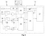
- FIG. 6shows schematically the analogue signal processing for the system
- FIG. 7shows schematically an overview of partial processes of the system.
- FIGS. 1 a and 1 Bwhich illustrate a vessel provided with a system in accordance with the invention, hereinafter referred to as a marine laser-radar-system, abbreviated MLR system.
- the MLR systemcomprises a sweeping unit 10 (sweeping head) (shown enlarged in FIG. 1 c ), a control unit 11 and an operator panel (screen) 12 (shown in FIG. 1 d ).
- the sweeping unit 10is arranged on a mast or to another platform above the wheel house roof to a vessel having best possible sight to the observation area.
- the control unit 11is mounted within the wheel house to the vessel and integrated with existing power supply, navigation equipment, monitors and internal communication to show both video and radar pictures, and to notify about detected obstructions in a planned vessel course.
- the MLR systemcan search a sector around a centre axis 13 by sweeping an infrared laser beam vertically within a vertical sector 14 and horizontally within a horizontal sector 15 or by a continuous rotation in the horizontal plane (as for a traditional radar).
- the centre axis 13can be selected arbitrarily within 360 degrees horizontally from the operator panel.
- the distance to an object 16 within the sweeping sectoris measured by using pulsed laser beam and by measuring the time between transmission and reception of the reflected laser pulse, like traditional radar. That is the reason for the term Laser-Radar (LR).
- a laserilluminates a small area 17 (footprint, FIG. 1 b , FIG. 2 ) with an extension defined by the opening angels of the laser and the distance to the object 16 .
- this areais depicted on an optical detector which can be a simple detector element or a matrix (array) of detector elements.
- an optical detectorwhich can be a simple detector element or a matrix (array) of detector elements.
- a detector matrixBy using a detector matrix, a space like resolution within the illuminated area is achieved, given by the number of elements in the detector matrix.
- An example of distribution of footprint and resolution elements in a plane perpendicular to the centre axis 13is shown in FIG. 2 for a square detector matrix having 4 ⁇ 4 (16) elements.
- This regular patternis produced by sweeping the laser beam about two axis by means of two independent sweep mechanisms 19 , 20 (sweepers), illustrated in FIG. 3 .
- the first sweeping mechanism 19distributes the laser spots along a line 18
- the other sweeping mechanism 20displaces these lines parallel so that they fill the whole view field in azimuth.
- the laser rate of fire and line displacementis done so that the field of view is covered by partly overlapping laser spots.
- a continuous sampling of the sweep sectoris performed by turning the direction of the horizontal sweep each time the sector limits has been reached or by a continuous horizontal rotation.
- the figureshows a block diagram of a vessel installation.
- the sweeping unit 10comprises an optical/sensor and pulse processing unit 21 , a laser controlling unit 22 and an optical window 23
- the controller 11comprises a sweep engine controller 24 , signal processor 25 , time controller and controller electronics 26 , and a picture and control processor 27 .
- the picture and control processor 27is provided with outputs for connecting to the operator control unit 12 and the vessel navigation and communication system 28 .
- the illumination source in the systemis preferably an eye safe IR laser 30 having a fibre-optical 31 feeding of the laser light to an optical collimator 32 which transforms the laser light to a beam 33 having a footprint adapted to the distribution of the elements in the detector matrix. A small part of this beam 33 is directed to an optical detector 34 via a beam divider 35 for monitoring of the output power and generation of a start pulse for the distance measurement.
- the optical/sensor unit 21comprises an optical filter 36 for elimination of background light, a collector lens (objective) 37 for reception of the filtered light reflected back from objects 16 within the field of view, and an optical detector 38 in focus of a receptor objective.
- the receptor objective 37can be a non-spherical Fresnel lens or other lens combinations, possibly telescope, having a low F-number and with a resolution ability better than the dimensions of the detector elements in the optical detector 34 .
- the first sweeping mechanism 19(line sweeper) comprises two optical deflection elements 43 , 44 which are driven by two engines 45 , 46 having internal rotors.
- the deflection elements 43 , 44can be wedge prisms (Risley prisms), optical transmission grids (“Volume Bragg Grating, VBG”) or diffractive optical elements (DOE), all having the characteristic that they deflect an incoming optical beam by a fixed angle.
- VBGoptical transmission grid
- DOEdiffractive optical element
- VBGoptical transmission grid
- the laser beam and the receptor field of vieware deflected by the second sweeping mechanism 20 which is a mirror surface 47 , about 45 degrees relative to the main axis 40 of the sweeping unit 10 and which is rotated about the main axis 40 by means of an engine 41 (azimuth sweeper).
- the orientation of the line sweepmust be turned synchronically with the azimuth sweep, so that the sweep line is situated in the inlet plan normally to the mirror plane. This is performed by controlling the phase of the second sweep engine 46 in relation to the first engine 45 (explained in further detail below in connection with FIG. 5 d ).
- the sweep patterncan also be stabilized with regard to rolling movements of the vessel by the phase controlling of the two sweep engines 45 , 46 mentioned above.
- the mirror 47can be tilted about an axis 48 perpendicular to the main axis 40 by means of an engine 49 to stabilize the sweep pattern in relation to the horizontal plane from stamping movements of the vessel.
- all components in the sweep unit 10are mounted in a water proof cylindrical house 50 with a cylindrical window 34 for transmission of laser light and reflected light from illuminated objects 16 within the field of view.
- the drawingsshow the principle of the first sweeping mechanism 19 , which is a so-called line sweeper.
- a perpendicularly incoming laser beamis deflected in a direction 51 perpendicular to the stripe pattern (main direction) in a DOE/VBG 43 , and when this rotates about the main axis the beam will describe a circle 52 in a plan perpendicular to the main axis 40 ( FIG. 5 a ).
- the beamwill be deflected again in a direction determined by the main direction of the same.
- the deviation from a straight lineis caused by the distance between the DOE/VBG's 43 , 44 and equals the diameter of the circle 52 which the beam from the first DOE/VBG 43 describes on the other DOE/VBG 44 (by a magnitude of 1 mm).
- the directionwill be the same, independent of this displacement, resulting in a negligible deviation at longer distances.
- the described sweep arrangementalso enables stabilization of the sweep pattern for rolling and stamping movements, including small course deviations (gearing) of the vessel in a relatively simple manner.
- a rotation of the sweep line 53 a small angle out of the inlet plane 54 for the mirror surface 47results in a similar rotation of the vertical sweep lines 17 .
- a tilting of the mirror 47 about the second axis 48will move the sweep pattern up or down in relation to the horizontal plane. If the laser beam is oriented along the vessel longitudinal axis (rolling axis), a rolling movement will be compensated by turning the sweep line 53 an angle equal to the rolling angle but with opposite sign.
- the mirror 47in order to compensate for stamping movements, the mirror 47 must be rotated an angle equal to the stamping angle, but with opposite sign. Small deviations from planned course (gearing) are corrected by turning the mirror 47 about the main axis 40 . For other orientations (azimuth) of the laser beam, the compensation angles will be determined by known transformations of the rolling, stamping and gearing angles.
- the two DOE/VBG 43 , 44 in the first sweeping mechanism 19are preferably mounted in the rotor part of the conventional brush-free DC engines which rotate on a turbine type bearing.
- Conventional angle encodersrecord position and speed of the DOE/VBG 43 , 44 .
- the sweep engine controller 24preferably consists of conventional electronic servomotor units which adjust speed and phase of the DOE/VBG 43 , 44 based upon input signals from positioning sensors (angle encoders) and selected values for sweeping direction and sweeping speed from the operator control unit 11 .
- the second sweeping mechanism 20is preferably controlled by a conventional step motor/driving unit with an integrated angle encoder.
- the motor steppingis synchronized with the first sweeping mechanism 19 , so that the beginning of the step starts immediately before the sweep line 53 has reached the extreme point and is terminated when the sweep line 53 starts to move in the opposite direction.
- the motor 49 for stabilization of the sweep mirror 47 in the second sweeping mechanism 44is preferably also a conventional servomotor/driving unit with an integrated angle encoder controlled by the rolling and stamping angle information provided by the vessel navigation system (attitude sensors), including the horizontal (azimuth) direction of the laser beam 33 .
- the time controller and controller electronics unit 26provides starting pulses to the laser 30 and the pulse processing unit 21 processes the pulse signals from the photo detectors to extract reflected intensity and distance to objects 16 within the field of vision of the detector, including output power to the laser 30 .
- the signal processingis typical for new radar and laser-radar systems and is illustrated schematically in FIG. 6 .
- a pulse and function generator 55receives synchronization pulses (master trig, MT) from the signal and controller processor 27 when the sweeping unit 10 has reached an angle position within the regular sweep pattern, and generates a starting signal to the laser 30 which causes the latter to emit a laser pulse.
- master trig, MTmaster trig
- the current pulse(s) from the photo detector(s) 38is amplified in current/voltage amplifiers 56 and move on to TVG amplifiers 57 (time-varied-gain), where the amplification increases with time to compensate for weakening caused by spherical diffusion and optical attenuation in the stratum of air between the sweeping unit 10 and reflecting objects 16 .
- the time function for the amplificationis selected from the operator panel 11 and is generated in the pulse and function generator 55 by means of clock pulses from a digitalization unit 58 .
- a final set of time functions which are representative to different sight conditions (clear, hazy, rain, fog)is implemented in the pulse and function generator 55 .
- the received pulses from the TVG amplifiers 57proceed further on to an analogous digitalization unit 58 which also receives the signal from the reference detector 34 . Then, the digitalized signals are sent via cable to a signal processor 25 in the controller unit 11 .
- the digitalization unit 58preferably comprises fast A/D converters, data buffers and clock and transfers the digitalized signals to the signal processor 25 where distance and peak value for the return signals are calculated.
- both the signal and image processorsare based upon a conventional modular DSP architecture where the particular processes are distribute on several digital signal processors (DSP), controlled by a PC processor (control processor).
- DSPdigital signal processors
- FIG. 7shows schematically an overview of the individual sub processes.
- the time course for the received signal between each laser pulse emittedis analyzed with regard to instances of return pulses which exceed a threshold given by the signal to noise relationship and a given probability of false detection.
- the first pulseis always the outgoing laser pulse, and the point of maximum which represents the peak effect of the laser pulse from the reference detector 34 is registered together with an accurate point in time for the emission.
- the remaining pulseseither represent backscattered light from the stratum of air (rain, snow etc.), reflection from objects 16 or false noise pulses.
- the detector 34is based upon the simple hypothesis that the laser pulse is stopped by solid objects 16 with an extension larger than the laser spot, so that the last detected pulse with high probability represents reflection from the object 16 .
- the search processis therefore started in the end of the time series and back in time.
- the last pulseis registered in the same way as the laser pulse, with a peak value and an accurate interpolated value for the detection point in time.
- the peak valueis normalized with regard to the peak effect of the laser to correlate variations in sent effect, and the distance to the object is calculated by subtracting the point in time of emitted pulse and by multiplying with half of the speed of light (because of two-way transmission).
- the registered intensity (peak) and distance valuesare sent to the line generator where all values for a vertical sweep line are accumulated. Then, every point is marked with the vertical sweep angle from the sweep angle decoder and every line is marked with the horizontal sweep angle including a time mark from an external time reference.
- the intensity valuesare correlated further with regard to deviation from the selected TVG function (radiometric correlation) so that the intensity values represent reflectivity of the objects 16 and not differences in illumination.
- navigation dataposition, course, speed, rolling, stamping and throw
- data pointsfrom relative distance, azimuth and vertical angle to geographical coordinates; latitude, longitude and elevation above sea level. This is performed in the process called “geometrical creation” ( FIG. 7 ). If the laser beam and the field of view have not been formerly stabilized as described above, we can use navigation data to correlate for rolling and stamping movements including course deviations (gearing) prior to presentation on the graphical monitor.
- the correlated line dataare collected in a sweep data storage which represents a complete sweep image.
- the sweep data storageis updated line by line if new lines are being generated.
- the graphical presentation processorpicks data from the sweep data storage and generates sweep images both in central projection like a camera and in vertical projection (PPI) as for radar.
- the ARPA moduleanalyzes the sweep storage for detection of objects 16 within the sweep sector. Detected objects 16 are collected in an object database and classified as stationary or movable based upon correlation from sweep to sweep. A closest distance (CPA) and time to closest distance (TCPA) is calculated for all objects 16 as for conventional ARPA radar. Should the CPA reside within a defined safety zone for the vessel, an ARPA message in accordance with NMEA/IEC standard 4 is sent to other navigation monitors (ECDIS, Radar), and to the vessel alarm system.
- CPAclosest distance
- TCPAtime to closest distance
- the described marine laser radar systemcan be implemented in numerous alternative ways by alternative selections of components. It is already mentioned that the line sweeper 45 , 46 ( FIG. 4 ) can be implemented with numerous optical components 43 , 44 ( FIG. 4 ), all having the characteristic of being able to deflect a laser beam at a fixed angle in relation to the incoming beam, such as Risley prisms, optical transmission grids and holographic elements (HOE). Among theses, optical transmission grids (“Volume Bragg Grating, VBG”) and HOE's, point themselves out as suitable components in the rotating construction described here. The possibility of using an array of detectors 38 ( FIG. 4 ) has also been mentioned, to be able to increase the sweeping speed compared to the use of single detectors.
- the line sweeperconstitutes a critical element.
- the line sweepersare implemented by means of vibrating single mirrors or rotating multi facet mirrors. With synchronous sweeping of laser beam and larger receiver apertures by means of mirrors, which is required in depicting sweep systems, these systems often attain large dimensions (multi facet mirrors) and are power demanding (vibrating mirrors), wherein vibrating mirrors also can generate large vibrations in the optical-mechanical construction.
- the whole sweeping unitcan be rotated by means of an external motor.
- the cylindrical window 23FIG. 4
- the cylindrical window 23could be replaced by a smaller level window which covers the field of view of the detection system.
- the laser beamcan be folded into the field of view of the receiver before the line sweeper by means of mirrors or prisms. This can reduce the dimensions of the deflection elements 43 , 44 , but will also reduce the reception area.
Landscapes
- Physics & Mathematics (AREA)
- Engineering & Computer Science (AREA)
- Electromagnetism (AREA)
- Computer Networks & Wireless Communication (AREA)
- General Physics & Mathematics (AREA)
- Radar, Positioning & Navigation (AREA)
- Remote Sensing (AREA)
- Optical Radar Systems And Details Thereof (AREA)
- Traffic Control Systems (AREA)
Abstract
Description
- 1.1NEK EN 60825-11IEC 60825-1, Ed 1.2, 2001-08; Safety of laser products—Part 1: Equipment classification, requirements and user's guide.
- 2.1Performance Standards for Night Vision Equipment for High-Speed Craft (HSC), MSC 72/Add.1/
Annex 12, Res. MSC.94(72) (adopted on 22 May 2000) - 3.1ISO 16273:2003(E); Ships and marine technology—Night vision equipment for high-speed craft Operational and performance requirements, methods of testing and required test results
- 4.1NMEA 0183 v3.01, NMEA 2000
Claims (14)
Applications Claiming Priority (3)
| Application Number | Priority Date | Filing Date | Title |
|---|---|---|---|
| NO20083495 | 2008-08-12 | ||
| NO20083495ANO332432B1 (en) | 2008-08-12 | 2008-08-12 | System for detection and imaging of objects in the trajectory of marine vessels |
| PCT/NO2009/000286WO2010024683A1 (en) | 2008-08-12 | 2009-08-12 | System for the detection and the depiction of objects in the path of marine vessels |
Publications (2)
| Publication Number | Publication Date |
|---|---|
| US20110128162A1 US20110128162A1 (en) | 2011-06-02 |
| US8665122B2true US8665122B2 (en) | 2014-03-04 |
Family
ID=41721673
Family Applications (1)
| Application Number | Title | Priority Date | Filing Date |
|---|---|---|---|
| US13/055,003Active2030-05-31US8665122B2 (en) | 2008-08-12 | 2009-08-12 | System for the detection and the depiction of objects in the path of marine vessels |
Country Status (7)
| Country | Link |
|---|---|
| US (1) | US8665122B2 (en) |
| EP (1) | EP2310875A4 (en) |
| JP (1) | JP5702720B2 (en) |
| AU (1) | AU2009286254B2 (en) |
| CA (1) | CA2732418C (en) |
| NO (1) | NO332432B1 (en) |
| WO (1) | WO2010024683A1 (en) |
Cited By (12)
| Publication number | Priority date | Publication date | Assignee | Title |
|---|---|---|---|---|
| US9418558B1 (en)* | 2014-03-25 | 2016-08-16 | The United States Of America As Represented By Secretary Of The Navy | Autonomous collision avoidance navigation system and method |
| US10032381B2 (en)* | 2011-05-23 | 2018-07-24 | Ion Geophysical Corporation | Marine threat monitoring and defense system |
| US10120068B1 (en) | 2017-04-28 | 2018-11-06 | SZ DJI Technology Co., Ltd. | Calibration of laser sensors |
| US10148060B2 (en) | 2017-03-29 | 2018-12-04 | SZ DJI Technology Co., Ltd. | Lidar sensor system with small form factor |
| US10152771B1 (en) | 2017-07-31 | 2018-12-11 | SZ DJI Technology Co., Ltd. | Correction of motion-based inaccuracy in point clouds |
| US10295659B2 (en) | 2017-04-28 | 2019-05-21 | SZ DJI Technology Co., Ltd. | Angle calibration in light detection and ranging system |
| US10371802B2 (en) | 2017-07-20 | 2019-08-06 | SZ DJI Technology Co., Ltd. | Systems and methods for optical distance measurement |
| US10436884B2 (en) | 2017-04-28 | 2019-10-08 | SZ DJI Technology Co., Ltd. | Calibration of laser and vision sensors |
| US10539663B2 (en) | 2017-03-29 | 2020-01-21 | SZ DJI Technology Co., Ltd. | Light detecting and ranging (LIDAR) signal processing circuitry |
| US10554097B2 (en) | 2017-03-29 | 2020-02-04 | SZ DJI Technology Co., Ltd. | Hollow motor apparatuses and associated systems and methods |
| US10641875B2 (en) | 2017-08-31 | 2020-05-05 | SZ DJI Technology Co., Ltd. | Delay time calibration of optical distance measurement devices, and associated systems and methods |
| US10899471B2 (en) | 2017-01-24 | 2021-01-26 | SZ DJI Technology Co., Ltd. | Flight indication apparatuses, systems and associated methods |
Families Citing this family (36)
| Publication number | Priority date | Publication date | Assignee | Title |
|---|---|---|---|---|
| KR101113312B1 (en)* | 2009-12-10 | 2012-03-13 | 이성종 | system for preventing collision of vessel and method for preventing collision of vessel |
| JP5561183B2 (en)* | 2011-01-21 | 2014-07-30 | アイコム株式会社 | Target identification device and target movement prediction program |
| JP2012225821A (en)* | 2011-04-21 | 2012-11-15 | Ihi Corp | Laser sensor device |
| JP5741833B2 (en)* | 2011-05-10 | 2015-07-01 | 株式会社Ihi | Laser radar apparatus and laser radar method |
| CA2871502C (en) | 2012-04-26 | 2021-06-08 | Neptec Design Group Ltd. | High speed 360 degree scanning lidar head |
| ITUD20120187A1 (en)* | 2012-11-07 | 2014-05-08 | Eidon Lab S C A R L | EQUIPMENT AND DETECTION PROCEDURE TO DETECT BARRIERS TO NAVIGATION BY WATER |
| JP6069628B2 (en)* | 2012-12-03 | 2017-02-01 | 北陽電機株式会社 | Deflection device, optical scanning device, and scanning distance measuring device |
| US9135826B2 (en)* | 2012-12-26 | 2015-09-15 | Sap Se | Complex event processing for moving objects |
| IL224130A (en)* | 2013-01-07 | 2017-01-31 | Brightway Vision Ltd | Object detection by whirling system |
| US10247822B2 (en) | 2013-03-14 | 2019-04-02 | Navico Holding As | Sonar transducer assembly |
| NO335488B1 (en)* | 2013-03-22 | 2014-12-22 | Kongsberg Seatex As | Position reference system and method for positioning and tracking one or more objects |
| EP3027501A1 (en) | 2013-08-02 | 2016-06-08 | Garmin Switzerland GmbH | Marine navigation device with improved contour lines |
| EP2866051B1 (en) | 2013-10-23 | 2018-10-03 | Ladar Limited | A laser detection and ranging device for detecting an object under a water surface |
| KR101541144B1 (en)* | 2014-08-27 | 2015-08-03 | 국방과학연구소 | Method for Underwater Object Location Determination using Proximity Sensor of Compass Direction and Device thereof |
| RU2584920C1 (en)* | 2014-10-31 | 2016-05-20 | Российская Федерация, от имени которой выступает государственный заказчик Министерство промышленности и торговли Российской Федерации (Минпромторг России) | Set of personal navigation equipment for small ship floating crafts |
| US10597130B2 (en) | 2015-01-15 | 2020-03-24 | Navico Holding As | Trolling motor with a transducer array |
| US11209543B2 (en) | 2015-01-15 | 2021-12-28 | Navico Holding As | Sonar transducer having electromagnetic shielding |
| US10539666B2 (en) | 2015-01-21 | 2020-01-21 | Mitsubishi Electric Corporation | Laser radar device |
| JP6541365B2 (en)* | 2015-02-16 | 2019-07-10 | 株式会社トプコン | Posture detection device and data acquisition device |
| JP6616077B2 (en)* | 2015-02-16 | 2019-12-04 | 株式会社トプコン | Measuring device and 3D camera |
| US9784832B2 (en) | 2015-03-05 | 2017-10-10 | Navico Holding As | Systems and associated methods for producing a 3D sonar image |
| FR3045991B1 (en)* | 2015-12-17 | 2018-09-07 | BSB Artificial Intelligence GmbH | METHOD AND DEVICE FOR DETECTING A FLOATING OBJECT FOR A BOAT |
| US10719077B2 (en) | 2016-10-13 | 2020-07-21 | Navico Holding As | Castable sonar devices and operations in a marine environment |
| US10488494B2 (en) | 2017-04-03 | 2019-11-26 | Ford Global Technologies, Llc | Sensor apparatus |
| US10338198B2 (en) | 2017-04-03 | 2019-07-02 | Ford Global Technologies, Llc | Sensor apparatus |
| KR101967049B1 (en)* | 2017-06-28 | 2019-04-09 | 경성대학교 산학협력단 | Apparatus for providing object information for heavy machinery using lidar and camera |
| EP3424304B1 (en)* | 2017-07-04 | 2021-05-26 | Andreas Stihl AG & Co. KG | Garden and/or forest system for wireless determination of distances |
| JP6293960B1 (en)* | 2017-08-10 | 2018-03-14 | 善郎 水野 | Collision avoidance support system |
| CN108627851B (en)* | 2018-04-20 | 2021-05-11 | 金华市蓝海光电技术有限公司 | Integrated rotary machine core for laser radar sensor |
| WO2019232585A1 (en)* | 2018-06-07 | 2019-12-12 | Baraja Pty Ltd | An optical beam director |
| US11921218B2 (en)* | 2018-11-30 | 2024-03-05 | Garmin Switzerland Gmbh | Marine vessel LIDAR system |
| CN111749201B (en)* | 2020-06-22 | 2021-06-18 | 上海中交水运设计研究有限公司 | Normal-submerged pontoon anchoring stress air bag preposed arresting system for preventing ship collision of bridge body |
| KR20220011464A (en) | 2020-07-21 | 2022-01-28 | 삼성전자주식회사 | Robot and contrl method thereof |
| EP4263342A1 (en)* | 2020-12-21 | 2023-10-25 | Seesafe Innovation Srl | Detection apparatus of floating bodies on sea |
| US20240175984A1 (en)* | 2021-03-15 | 2024-05-30 | Pioneer Corporation | Information processing device, control method, program, and storage medium |
| US12293537B2 (en)* | 2021-05-28 | 2025-05-06 | Beijing Boe Optoelectronics Technology Co., Ltd. | Virtual reality experience safe area updating method and apparatus |
Citations (7)
| Publication number | Priority date | Publication date | Assignee | Title |
|---|---|---|---|---|
| US6344937B1 (en)* | 1999-03-03 | 2002-02-05 | Raytheon Company | Beam steering optical arrangement using Risley prisms with surface contours for aberration correction |
| JP2004150898A (en) | 2002-10-29 | 2004-05-27 | Mitsubishi Heavy Ind Ltd | Marine search system and marine search method |
| US20040233414A1 (en)* | 2003-05-19 | 2004-11-25 | Jamieson James R. | Laser perimeter awareness system |
| US20060028533A1 (en)* | 2004-08-06 | 2006-02-09 | Tomohiro Nakajima | Optical scanning unit and image forming apparatus |
| US20070035624A1 (en) | 1999-09-03 | 2007-02-15 | Arete Associates | Lidar with streak-tube imaging, including hazard detection in marine applications; related optics |
| US20070165967A1 (en) | 2006-01-16 | 2007-07-19 | Omron Corporation | Object detector |
| US20080169969A1 (en)* | 2006-04-27 | 2008-07-17 | Takashi Shirai | Radar device |
Family Cites Families (20)
| Publication number | Priority date | Publication date | Assignee | Title |
|---|---|---|---|---|
| JPS62231190A (en)* | 1986-04-01 | 1987-10-09 | Yamaha Motor Co Ltd | Collision warning device |
| JPH04110685A (en)* | 1990-08-30 | 1992-04-13 | Nec Corp | Laser radar device |
| JPH05100181A (en)* | 1991-10-04 | 1993-04-23 | Minolta Camera Co Ltd | Scanning system |
| US5249046A (en) | 1992-03-30 | 1993-09-28 | Kaman Aerospace Corporation | Method and apparatus for three dimensional range resolving imaging |
| US5465142A (en) | 1993-04-30 | 1995-11-07 | Northrop Grumman Corporation | Obstacle avoidance system for helicopters and other aircraft |
| JPH07218633A (en)* | 1993-12-08 | 1995-08-18 | Nikon Corp | Distance measuring device |
| JPH08105971A (en)* | 1994-10-05 | 1996-04-23 | Hitachi Ltd | Distance measuring method and apparatus using multi-pulse |
| US6005682A (en)* | 1995-06-07 | 1999-12-21 | Xerox Corporation | Resolution enhancement by multiple scanning with a low-resolution, two-dimensional sensor array |
| JP3646270B2 (en)* | 1995-07-17 | 2005-05-11 | 東急建設株式会社 | Traveling surveying instrument |
| JP3446466B2 (en)* | 1996-04-04 | 2003-09-16 | 株式会社デンソー | Reflection measuring device for inter-vehicle distance control device and inter-vehicle distance control device using the same |
| JP2874669B2 (en)* | 1996-10-31 | 1999-03-24 | 日本電気株式会社 | Laser radar |
| JP2998692B2 (en)* | 1997-04-18 | 2000-01-11 | 日本電気株式会社 | Laser radar measurement method and device |
| JPH1123709A (en)* | 1997-07-07 | 1999-01-29 | Nikon Corp | Distance measuring device |
| JPH11311671A (en)* | 1998-04-28 | 1999-11-09 | Mitsubishi Heavy Ind Ltd | Navigation obstruction detection steering device |
| JP3169074B2 (en)* | 1998-09-25 | 2001-05-21 | 日本電気株式会社 | Laser radar device |
| US6380871B1 (en)* | 1999-11-30 | 2002-04-30 | Optical Systems, Inc. | System for and method of searching for targets in a marine environment |
| JP2001183461A (en)* | 1999-12-27 | 2001-07-06 | Minolta Co Ltd | Distance-measuring device |
| JP2002277812A (en)* | 2001-03-22 | 2002-09-25 | Nec Corp | Laser scanning method and scanner |
| US7336407B1 (en)* | 2005-07-28 | 2008-02-26 | Lockheed Martin Corporation | Scanner/pointer apparatus having super-hemispherical coverage |
| US7697125B2 (en) | 2007-05-11 | 2010-04-13 | Rosemount Aerospace Inc. | Scanning ladar with adjustable operational parameters |
- 2008
- 2008-08-12NONO20083495Apatent/NO332432B1/enunknown
- 2009
- 2009-08-12JPJP2011522925Apatent/JP5702720B2/enactiveActive
- 2009-08-12WOPCT/NO2009/000286patent/WO2010024683A1/enactiveApplication Filing
- 2009-08-12EPEP09810269.2Apatent/EP2310875A4/ennot_activeCeased
- 2009-08-12CACA2732418Apatent/CA2732418C/enactiveActive
- 2009-08-12USUS13/055,003patent/US8665122B2/enactiveActive
- 2009-08-12AUAU2009286254Apatent/AU2009286254B2/enactiveActive
Patent Citations (7)
| Publication number | Priority date | Publication date | Assignee | Title |
|---|---|---|---|---|
| US6344937B1 (en)* | 1999-03-03 | 2002-02-05 | Raytheon Company | Beam steering optical arrangement using Risley prisms with surface contours for aberration correction |
| US20070035624A1 (en) | 1999-09-03 | 2007-02-15 | Arete Associates | Lidar with streak-tube imaging, including hazard detection in marine applications; related optics |
| JP2004150898A (en) | 2002-10-29 | 2004-05-27 | Mitsubishi Heavy Ind Ltd | Marine search system and marine search method |
| US20040233414A1 (en)* | 2003-05-19 | 2004-11-25 | Jamieson James R. | Laser perimeter awareness system |
| US20060028533A1 (en)* | 2004-08-06 | 2006-02-09 | Tomohiro Nakajima | Optical scanning unit and image forming apparatus |
| US20070165967A1 (en) | 2006-01-16 | 2007-07-19 | Omron Corporation | Object detector |
| US20080169969A1 (en)* | 2006-04-27 | 2008-07-17 | Takashi Shirai | Radar device |
Cited By (21)
| Publication number | Priority date | Publication date | Assignee | Title |
|---|---|---|---|---|
| US10032381B2 (en)* | 2011-05-23 | 2018-07-24 | Ion Geophysical Corporation | Marine threat monitoring and defense system |
| US9418558B1 (en)* | 2014-03-25 | 2016-08-16 | The United States Of America As Represented By Secretary Of The Navy | Autonomous collision avoidance navigation system and method |
| US10899471B2 (en) | 2017-01-24 | 2021-01-26 | SZ DJI Technology Co., Ltd. | Flight indication apparatuses, systems and associated methods |
| US10539663B2 (en) | 2017-03-29 | 2020-01-21 | SZ DJI Technology Co., Ltd. | Light detecting and ranging (LIDAR) signal processing circuitry |
| US11336074B2 (en) | 2017-03-29 | 2022-05-17 | SZ DJI Technology Co., Ltd. | LIDAR sensor system with small form factor |
| US10148060B2 (en) | 2017-03-29 | 2018-12-04 | SZ DJI Technology Co., Ltd. | Lidar sensor system with small form factor |
| US10714889B2 (en) | 2017-03-29 | 2020-07-14 | SZ DJI Technology Co., Ltd. | LIDAR sensor system with small form factor |
| US10554097B2 (en) | 2017-03-29 | 2020-02-04 | SZ DJI Technology Co., Ltd. | Hollow motor apparatuses and associated systems and methods |
| US10295659B2 (en) | 2017-04-28 | 2019-05-21 | SZ DJI Technology Co., Ltd. | Angle calibration in light detection and ranging system |
| US10436884B2 (en) | 2017-04-28 | 2019-10-08 | SZ DJI Technology Co., Ltd. | Calibration of laser and vision sensors |
| US10698092B2 (en) | 2017-04-28 | 2020-06-30 | SZ DJI Technology Co., Ltd. | Angle calibration in light detection and ranging system |
| US10859685B2 (en) | 2017-04-28 | 2020-12-08 | SZ DJI Technology Co., Ltd. | Calibration of laser sensors |
| US10884110B2 (en) | 2017-04-28 | 2021-01-05 | SZ DJI Technology Co., Ltd. | Calibration of laser and vision sensors |
| US10120068B1 (en) | 2017-04-28 | 2018-11-06 | SZ DJI Technology Co., Ltd. | Calibration of laser sensors |
| US11460563B2 (en) | 2017-04-28 | 2022-10-04 | SZ DJI Technology Co., Ltd. | Calibration of laser sensors |
| US10371802B2 (en) | 2017-07-20 | 2019-08-06 | SZ DJI Technology Co., Ltd. | Systems and methods for optical distance measurement |
| US11982768B2 (en) | 2017-07-20 | 2024-05-14 | SZ DJI Technology Co., Ltd. | Systems and methods for optical distance measurement |
| US10152771B1 (en) | 2017-07-31 | 2018-12-11 | SZ DJI Technology Co., Ltd. | Correction of motion-based inaccuracy in point clouds |
| US11238561B2 (en) | 2017-07-31 | 2022-02-01 | SZ DJI Technology Co., Ltd. | Correction of motion-based inaccuracy in point clouds |
| US11961208B2 (en) | 2017-07-31 | 2024-04-16 | SZ DJI Technology Co., Ltd. | Correction of motion-based inaccuracy in point clouds |
| US10641875B2 (en) | 2017-08-31 | 2020-05-05 | SZ DJI Technology Co., Ltd. | Delay time calibration of optical distance measurement devices, and associated systems and methods |
Also Published As
| Publication number | Publication date |
|---|---|
| EP2310875A4 (en) | 2014-03-05 |
| US20110128162A1 (en) | 2011-06-02 |
| NO20083495L (en) | 2010-02-15 |
| WO2010024683A1 (en) | 2010-03-04 |
| AU2009286254A1 (en) | 2010-03-04 |
| JP2011530712A (en) | 2011-12-22 |
| EP2310875A1 (en) | 2011-04-20 |
| CA2732418A1 (en) | 2010-03-04 |
| CA2732418C (en) | 2016-09-27 |
| AU2009286254B2 (en) | 2015-01-29 |
| NO332432B1 (en) | 2012-09-17 |
| JP5702720B2 (en) | 2015-04-15 |
Similar Documents
| Publication | Publication Date | Title |
|---|---|---|
| US8665122B2 (en) | System for the detection and the depiction of objects in the path of marine vessels | |
| US6542227B2 (en) | System and method of measuring flow velocity in three axes | |
| US6556282B2 (en) | Combined LOAS and LIDAR system | |
| US6380871B1 (en) | System for and method of searching for targets in a marine environment | |
| US7683928B2 (en) | Lidar with streak-tube imaging, including hazard detection in marine applications; related optics | |
| US6650407B2 (en) | Wide field scanning laser obstacle awareness system | |
| US7787134B2 (en) | Multiple fanned laser beam metrology system | |
| EP2866047B1 (en) | A detection system for detecting an object on a water surface | |
| EP3077768B1 (en) | Distance measurement instrument with scanning function | |
| US6665063B2 (en) | Distributed laser obstacle awareness system | |
| US4926050A (en) | Scanning laser based system and method for measurement of distance to a target | |
| AU2002322525A1 (en) | System and method of measuring flow velocity in three axes | |
| US20190120965A1 (en) | Method and system of digital light processing and light detection and ranging for guided autonomous vehicles | |
| KR100351018B1 (en) | Arrangement for target detection | |
| US20180172833A1 (en) | Laser repeater | |
| Redman et al. | Streak tube imaging lidar (STIL) for 3-D imaging of terrestrial targets | |
| WO2021034212A1 (en) | Laser optical location station | |
| WO2023166512A1 (en) | Increasing signal to noise ratio of a pixel of a lidar system | |
| Laurin et al. | Eye-safe imaging and tracking laser scanner system for space applications | |
| Neuwirth et al. | Polarization and turbulence effects measured at the Nettuno Trails Italy, 1998 | |
| Mandlburger | 2.6 UAV laser scanning | |
| Ruiz et al. | Practitioners Papers |
Legal Events
| Date | Code | Title | Description |
|---|---|---|---|
| AS | Assignment | Owner name:JK VISION AS, NORWAY Free format text:ASSIGNMENT OF ASSIGNORS INTEREST;ASSIGNOR:KLEPSVIK, JOHN O.;REEL/FRAME:025752/0170 Effective date:20110128 | |
| AS | Assignment | Owner name:KONGSBERG SEATEX AS, NORWAY Free format text:ASSIGNMENT OF ASSIGNORS INTEREST;ASSIGNOR:JK VISION AS;REEL/FRAME:026909/0871 Effective date:20110815 | |
| STCF | Information on status: patent grant | Free format text:PATENTED CASE | |
| MAFP | Maintenance fee payment | Free format text:PAYMENT OF MAINTENANCE FEE, 4TH YEAR, LARGE ENTITY (ORIGINAL EVENT CODE: M1551) Year of fee payment:4 | |
| MAFP | Maintenance fee payment | Free format text:PAYMENT OF MAINTENANCE FEE, 8TH YEAR, LARGE ENTITY (ORIGINAL EVENT CODE: M1552); ENTITY STATUS OF PATENT OWNER: LARGE ENTITY Year of fee payment:8 | |
| AS | Assignment | Owner name:KONGSBERG MARITIME AS, NORWAY Free format text:ASSIGNMENT OF ASSIGNORS INTEREST;ASSIGNOR:KONGSBERG SEATEX AS;REEL/FRAME:061774/0582 Effective date:20221109 | |
| AS | Assignment | Owner name:KONGSBERG DISCOVERY AS, NORWAY Free format text:ASSIGNMENT OF ASSIGNORS INTEREST;ASSIGNOR:KONGSBERG MARITIME AS;REEL/FRAME:065169/0915 Effective date:20231004 | |
| MAFP | Maintenance fee payment | Free format text:PAYMENT OF MAINTENANCE FEE, 12TH YEAR, LARGE ENTITY (ORIGINAL EVENT CODE: M1553); ENTITY STATUS OF PATENT OWNER: LARGE ENTITY Year of fee payment:12 |