US8663922B2 - Systems and methods for detecting multiple optical signals - Google Patents
Systems and methods for detecting multiple optical signalsDownload PDFInfo
- Publication number
- US8663922B2 US8663922B2US12/791,390US79139010AUS8663922B2US 8663922 B2US8663922 B2US 8663922B2US 79139010 AUS79139010 AUS 79139010AUS 8663922 B2US8663922 B2US 8663922B2
- Authority
- US
- United States
- Prior art keywords
- optical
- mtu
- reaction
- signal
- receptacle
- Prior art date
- Legal status (The legal status is an assumption and is not a legal conclusion. Google has not performed a legal analysis and makes no representation as to the accuracy of the status listed.)
- Active, expires
Links
Images


Classifications
- G—PHYSICS
- G01—MEASURING; TESTING
- G01N—INVESTIGATING OR ANALYSING MATERIALS BY DETERMINING THEIR CHEMICAL OR PHYSICAL PROPERTIES
- G01N21/00—Investigating or analysing materials by the use of optical means, i.e. using sub-millimetre waves, infrared, visible or ultraviolet light
- G01N21/62—Systems in which the material investigated is excited whereby it emits light or causes a change in wavelength of the incident light
- G01N21/63—Systems in which the material investigated is excited whereby it emits light or causes a change in wavelength of the incident light optically excited
- G01N21/64—Fluorescence; Phosphorescence
- G01N21/6428—Measuring fluorescence of fluorescent products of reactions or of fluorochrome labelled reactive substances, e.g. measuring quenching effects, using measuring "optrodes"
- C—CHEMISTRY; METALLURGY
- C12—BIOCHEMISTRY; BEER; SPIRITS; WINE; VINEGAR; MICROBIOLOGY; ENZYMOLOGY; MUTATION OR GENETIC ENGINEERING
- C12Q—MEASURING OR TESTING PROCESSES INVOLVING ENZYMES, NUCLEIC ACIDS OR MICROORGANISMS; COMPOSITIONS OR TEST PAPERS THEREFOR; PROCESSES OF PREPARING SUCH COMPOSITIONS; CONDITION-RESPONSIVE CONTROL IN MICROBIOLOGICAL OR ENZYMOLOGICAL PROCESSES
- C12Q1/00—Measuring or testing processes involving enzymes, nucleic acids or microorganisms; Compositions therefor; Processes of preparing such compositions
- C12Q1/68—Measuring or testing processes involving enzymes, nucleic acids or microorganisms; Compositions therefor; Processes of preparing such compositions involving nucleic acids
- C12Q1/6813—Hybridisation assays
- C—CHEMISTRY; METALLURGY
- C12—BIOCHEMISTRY; BEER; SPIRITS; WINE; VINEGAR; MICROBIOLOGY; ENZYMOLOGY; MUTATION OR GENETIC ENGINEERING
- C12Q—MEASURING OR TESTING PROCESSES INVOLVING ENZYMES, NUCLEIC ACIDS OR MICROORGANISMS; COMPOSITIONS OR TEST PAPERS THEREFOR; PROCESSES OF PREPARING SUCH COMPOSITIONS; CONDITION-RESPONSIVE CONTROL IN MICROBIOLOGICAL OR ENZYMOLOGICAL PROCESSES
- C12Q1/00—Measuring or testing processes involving enzymes, nucleic acids or microorganisms; Compositions therefor; Processes of preparing such compositions
- C12Q1/68—Measuring or testing processes involving enzymes, nucleic acids or microorganisms; Compositions therefor; Processes of preparing such compositions involving nucleic acids
- C12Q1/6844—Nucleic acid amplification reactions
- C12Q1/6851—Quantitative amplification
- G—PHYSICS
- G01—MEASURING; TESTING
- G01N—INVESTIGATING OR ANALYSING MATERIALS BY DETERMINING THEIR CHEMICAL OR PHYSICAL PROPERTIES
- G01N21/00—Investigating or analysing materials by the use of optical means, i.e. using sub-millimetre waves, infrared, visible or ultraviolet light
- G01N21/62—Systems in which the material investigated is excited whereby it emits light or causes a change in wavelength of the incident light
- G01N21/63—Systems in which the material investigated is excited whereby it emits light or causes a change in wavelength of the incident light optically excited
- G01N21/64—Fluorescence; Phosphorescence
- G01N21/645—Specially adapted constructive features of fluorimeters
- G01N21/6452—Individual samples arranged in a regular 2D-array, e.g. multiwell plates
- G01N21/6454—Individual samples arranged in a regular 2D-array, e.g. multiwell plates using an integrated detector array
- G—PHYSICS
- G01—MEASURING; TESTING
- G01N—INVESTIGATING OR ANALYSING MATERIALS BY DETERMINING THEIR CHEMICAL OR PHYSICAL PROPERTIES
- G01N21/00—Investigating or analysing materials by the use of optical means, i.e. using sub-millimetre waves, infrared, visible or ultraviolet light
- G01N21/75—Systems in which material is subjected to a chemical reaction, the progress or the result of the reaction being investigated
- G01N21/76—Chemiluminescence; Bioluminescence
- G—PHYSICS
- G01—MEASURING; TESTING
- G01N—INVESTIGATING OR ANALYSING MATERIALS BY DETERMINING THEIR CHEMICAL OR PHYSICAL PROPERTIES
- G01N35/00—Automatic analysis not limited to methods or materials provided for in any single one of groups G01N1/00 - G01N33/00; Handling materials therefor
- G01N35/00584—Control arrangements for automatic analysers
- G01N35/00594—Quality control, including calibration or testing of components of the analyser
- G01N35/00693—Calibration
- G—PHYSICS
- G01—MEASURING; TESTING
- G01N—INVESTIGATING OR ANALYSING MATERIALS BY DETERMINING THEIR CHEMICAL OR PHYSICAL PROPERTIES
- G01N35/00—Automatic analysis not limited to methods or materials provided for in any single one of groups G01N1/00 - G01N33/00; Handling materials therefor
- G01N35/00584—Control arrangements for automatic analysers
- G01N35/0092—Scheduling
- G—PHYSICS
- G01—MEASURING; TESTING
- G01N—INVESTIGATING OR ANALYSING MATERIALS BY DETERMINING THEIR CHEMICAL OR PHYSICAL PROPERTIES
- G01N35/00—Automatic analysis not limited to methods or materials provided for in any single one of groups G01N1/00 - G01N33/00; Handling materials therefor
- G01N35/0098—Automatic analysis not limited to methods or materials provided for in any single one of groups G01N1/00 - G01N33/00; Handling materials therefor involving analyte bound to insoluble magnetic carrier, e.g. using magnetic separation
- G—PHYSICS
- G01—MEASURING; TESTING
- G01N—INVESTIGATING OR ANALYSING MATERIALS BY DETERMINING THEIR CHEMICAL OR PHYSICAL PROPERTIES
- G01N35/00—Automatic analysis not limited to methods or materials provided for in any single one of groups G01N1/00 - G01N33/00; Handling materials therefor
- G01N35/0099—Automatic analysis not limited to methods or materials provided for in any single one of groups G01N1/00 - G01N33/00; Handling materials therefor comprising robots or similar manipulators
- G—PHYSICS
- G01—MEASURING; TESTING
- G01N—INVESTIGATING OR ANALYSING MATERIALS BY DETERMINING THEIR CHEMICAL OR PHYSICAL PROPERTIES
- G01N35/00—Automatic analysis not limited to methods or materials provided for in any single one of groups G01N1/00 - G01N33/00; Handling materials therefor
- G01N35/02—Automatic analysis not limited to methods or materials provided for in any single one of groups G01N1/00 - G01N33/00; Handling materials therefor using a plurality of sample containers moved by a conveyor system past one or more treatment or analysis stations
- G01N35/025—Automatic analysis not limited to methods or materials provided for in any single one of groups G01N1/00 - G01N33/00; Handling materials therefor using a plurality of sample containers moved by a conveyor system past one or more treatment or analysis stations having a carousel or turntable for reaction cells or cuvettes
- G—PHYSICS
- G01—MEASURING; TESTING
- G01N—INVESTIGATING OR ANALYSING MATERIALS BY DETERMINING THEIR CHEMICAL OR PHYSICAL PROPERTIES
- G01N35/00—Automatic analysis not limited to methods or materials provided for in any single one of groups G01N1/00 - G01N33/00; Handling materials therefor
- G01N35/02—Automatic analysis not limited to methods or materials provided for in any single one of groups G01N1/00 - G01N33/00; Handling materials therefor using a plurality of sample containers moved by a conveyor system past one or more treatment or analysis stations
- G01N35/026—Automatic analysis not limited to methods or materials provided for in any single one of groups G01N1/00 - G01N33/00; Handling materials therefor using a plurality of sample containers moved by a conveyor system past one or more treatment or analysis stations having blocks or racks of reaction cells or cuvettes
- G—PHYSICS
- G01—MEASURING; TESTING
- G01N—INVESTIGATING OR ANALYSING MATERIALS BY DETERMINING THEIR CHEMICAL OR PHYSICAL PROPERTIES
- G01N35/00—Automatic analysis not limited to methods or materials provided for in any single one of groups G01N1/00 - G01N33/00; Handling materials therefor
- G01N35/02—Automatic analysis not limited to methods or materials provided for in any single one of groups G01N1/00 - G01N33/00; Handling materials therefor using a plurality of sample containers moved by a conveyor system past one or more treatment or analysis stations
- G01N35/028—Automatic analysis not limited to methods or materials provided for in any single one of groups G01N1/00 - G01N33/00; Handling materials therefor using a plurality of sample containers moved by a conveyor system past one or more treatment or analysis stations having reaction cells in the form of microtitration plates
- G—PHYSICS
- G01—MEASURING; TESTING
- G01N—INVESTIGATING OR ANALYSING MATERIALS BY DETERMINING THEIR CHEMICAL OR PHYSICAL PROPERTIES
- G01N35/00—Automatic analysis not limited to methods or materials provided for in any single one of groups G01N1/00 - G01N33/00; Handling materials therefor
- G01N35/02—Automatic analysis not limited to methods or materials provided for in any single one of groups G01N1/00 - G01N33/00; Handling materials therefor using a plurality of sample containers moved by a conveyor system past one or more treatment or analysis stations
- G01N35/04—Details of the conveyor system
- G—PHYSICS
- G01—MEASURING; TESTING
- G01N—INVESTIGATING OR ANALYSING MATERIALS BY DETERMINING THEIR CHEMICAL OR PHYSICAL PROPERTIES
- G01N35/00—Automatic analysis not limited to methods or materials provided for in any single one of groups G01N1/00 - G01N33/00; Handling materials therefor
- G01N35/10—Devices for transferring samples or any liquids to, in, or from, the analysis apparatus, e.g. suction devices, injection devices
- G01N35/1002—Reagent dispensers
- B—PERFORMING OPERATIONS; TRANSPORTING
- B01—PHYSICAL OR CHEMICAL PROCESSES OR APPARATUS IN GENERAL
- B01L—CHEMICAL OR PHYSICAL LABORATORY APPARATUS FOR GENERAL USE
- B01L7/00—Heating or cooling apparatus; Heat insulating devices
- B01L7/52—Heating or cooling apparatus; Heat insulating devices with provision for submitting samples to a predetermined sequence of different temperatures, e.g. for treating nucleic acid samples
- G—PHYSICS
- G01—MEASURING; TESTING
- G01N—INVESTIGATING OR ANALYSING MATERIALS BY DETERMINING THEIR CHEMICAL OR PHYSICAL PROPERTIES
- G01N21/00—Investigating or analysing materials by the use of optical means, i.e. using sub-millimetre waves, infrared, visible or ultraviolet light
- G01N21/62—Systems in which the material investigated is excited whereby it emits light or causes a change in wavelength of the incident light
- G01N21/63—Systems in which the material investigated is excited whereby it emits light or causes a change in wavelength of the incident light optically excited
- G01N21/64—Fluorescence; Phosphorescence
- G01N2021/6417—Spectrofluorimetric devices
- G01N2021/6419—Excitation at two or more wavelengths
- G—PHYSICS
- G01—MEASURING; TESTING
- G01N—INVESTIGATING OR ANALYSING MATERIALS BY DETERMINING THEIR CHEMICAL OR PHYSICAL PROPERTIES
- G01N21/00—Investigating or analysing materials by the use of optical means, i.e. using sub-millimetre waves, infrared, visible or ultraviolet light
- G01N21/62—Systems in which the material investigated is excited whereby it emits light or causes a change in wavelength of the incident light
- G01N21/63—Systems in which the material investigated is excited whereby it emits light or causes a change in wavelength of the incident light optically excited
- G01N21/64—Fluorescence; Phosphorescence
- G01N2021/6417—Spectrofluorimetric devices
- G01N2021/6421—Measuring at two or more wavelengths
- G—PHYSICS
- G01—MEASURING; TESTING
- G01N—INVESTIGATING OR ANALYSING MATERIALS BY DETERMINING THEIR CHEMICAL OR PHYSICAL PROPERTIES
- G01N21/00—Investigating or analysing materials by the use of optical means, i.e. using sub-millimetre waves, infrared, visible or ultraviolet light
- G01N21/62—Systems in which the material investigated is excited whereby it emits light or causes a change in wavelength of the incident light
- G01N21/63—Systems in which the material investigated is excited whereby it emits light or causes a change in wavelength of the incident light optically excited
- G01N21/64—Fluorescence; Phosphorescence
- G01N21/6428—Measuring fluorescence of fluorescent products of reactions or of fluorochrome labelled reactive substances, e.g. measuring quenching effects, using measuring "optrodes"
- G01N2021/6432—Quenching
- G—PHYSICS
- G01—MEASURING; TESTING
- G01N—INVESTIGATING OR ANALYSING MATERIALS BY DETERMINING THEIR CHEMICAL OR PHYSICAL PROPERTIES
- G01N21/00—Investigating or analysing materials by the use of optical means, i.e. using sub-millimetre waves, infrared, visible or ultraviolet light
- G01N21/62—Systems in which the material investigated is excited whereby it emits light or causes a change in wavelength of the incident light
- G01N21/63—Systems in which the material investigated is excited whereby it emits light or causes a change in wavelength of the incident light optically excited
- G01N21/64—Fluorescence; Phosphorescence
- G01N21/6428—Measuring fluorescence of fluorescent products of reactions or of fluorochrome labelled reactive substances, e.g. measuring quenching effects, using measuring "optrodes"
- G01N2021/6439—Measuring fluorescence of fluorescent products of reactions or of fluorochrome labelled reactive substances, e.g. measuring quenching effects, using measuring "optrodes" with indicators, stains, dyes, tags, labels, marks
- G01N2021/6441—Measuring fluorescence of fluorescent products of reactions or of fluorochrome labelled reactive substances, e.g. measuring quenching effects, using measuring "optrodes" with indicators, stains, dyes, tags, labels, marks with two or more labels
- G—PHYSICS
- G01—MEASURING; TESTING
- G01N—INVESTIGATING OR ANALYSING MATERIALS BY DETERMINING THEIR CHEMICAL OR PHYSICAL PROPERTIES
- G01N35/00—Automatic analysis not limited to methods or materials provided for in any single one of groups G01N1/00 - G01N33/00; Handling materials therefor
- G01N2035/00346—Heating or cooling arrangements
- G01N2035/00356—Holding samples at elevated temperature (incubation)
- G—PHYSICS
- G01—MEASURING; TESTING
- G01N—INVESTIGATING OR ANALYSING MATERIALS BY DETERMINING THEIR CHEMICAL OR PHYSICAL PROPERTIES
- G01N35/00—Automatic analysis not limited to methods or materials provided for in any single one of groups G01N1/00 - G01N33/00; Handling materials therefor
- G01N2035/00465—Separating and mixing arrangements
- G01N2035/00524—Mixing by agitating sample carrier
- G—PHYSICS
- G01—MEASURING; TESTING
- G01N—INVESTIGATING OR ANALYSING MATERIALS BY DETERMINING THEIR CHEMICAL OR PHYSICAL PROPERTIES
- G01N35/00—Automatic analysis not limited to methods or materials provided for in any single one of groups G01N1/00 - G01N33/00; Handling materials therefor
- G01N35/00584—Control arrangements for automatic analysers
- G01N2035/0097—Control arrangements for automatic analysers monitoring reactions as a function of time
- G—PHYSICS
- G01—MEASURING; TESTING
- G01N—INVESTIGATING OR ANALYSING MATERIALS BY DETERMINING THEIR CHEMICAL OR PHYSICAL PROPERTIES
- G01N35/00—Automatic analysis not limited to methods or materials provided for in any single one of groups G01N1/00 - G01N33/00; Handling materials therefor
- G01N35/02—Automatic analysis not limited to methods or materials provided for in any single one of groups G01N1/00 - G01N33/00; Handling materials therefor using a plurality of sample containers moved by a conveyor system past one or more treatment or analysis stations
- G01N35/04—Details of the conveyor system
- G01N2035/0439—Rotary sample carriers, i.e. carousels
- G01N2035/0441—Rotary sample carriers, i.e. carousels for samples
- G—PHYSICS
- G01—MEASURING; TESTING
- G01N—INVESTIGATING OR ANALYSING MATERIALS BY DETERMINING THEIR CHEMICAL OR PHYSICAL PROPERTIES
- G01N35/00—Automatic analysis not limited to methods or materials provided for in any single one of groups G01N1/00 - G01N33/00; Handling materials therefor
- G01N35/02—Automatic analysis not limited to methods or materials provided for in any single one of groups G01N1/00 - G01N33/00; Handling materials therefor using a plurality of sample containers moved by a conveyor system past one or more treatment or analysis stations
- G01N35/04—Details of the conveyor system
- G01N2035/0439—Rotary sample carriers, i.e. carousels
- G01N2035/0443—Rotary sample carriers, i.e. carousels for reagents
- G—PHYSICS
- G01—MEASURING; TESTING
- G01N—INVESTIGATING OR ANALYSING MATERIALS BY DETERMINING THEIR CHEMICAL OR PHYSICAL PROPERTIES
- G01N35/00—Automatic analysis not limited to methods or materials provided for in any single one of groups G01N1/00 - G01N33/00; Handling materials therefor
- G01N35/02—Automatic analysis not limited to methods or materials provided for in any single one of groups G01N1/00 - G01N33/00; Handling materials therefor using a plurality of sample containers moved by a conveyor system past one or more treatment or analysis stations
- G01N35/04—Details of the conveyor system
- G01N2035/0439—Rotary sample carriers, i.e. carousels
- G01N2035/0444—Rotary sample carriers, i.e. carousels for cuvettes or reaction vessels
- G—PHYSICS
- G01—MEASURING; TESTING
- G01N—INVESTIGATING OR ANALYSING MATERIALS BY DETERMINING THEIR CHEMICAL OR PHYSICAL PROPERTIES
- G01N35/00—Automatic analysis not limited to methods or materials provided for in any single one of groups G01N1/00 - G01N33/00; Handling materials therefor
- G01N35/02—Automatic analysis not limited to methods or materials provided for in any single one of groups G01N1/00 - G01N33/00; Handling materials therefor using a plurality of sample containers moved by a conveyor system past one or more treatment or analysis stations
- G01N35/04—Details of the conveyor system
- G01N2035/0439—Rotary sample carriers, i.e. carousels
- G01N2035/0453—Multiple carousels working in parallel
- G01N2035/0455—Coaxial carousels
- G—PHYSICS
- G01—MEASURING; TESTING
- G01N—INVESTIGATING OR ANALYSING MATERIALS BY DETERMINING THEIR CHEMICAL OR PHYSICAL PROPERTIES
- G01N35/00—Automatic analysis not limited to methods or materials provided for in any single one of groups G01N1/00 - G01N33/00; Handling materials therefor
- G01N35/02—Automatic analysis not limited to methods or materials provided for in any single one of groups G01N1/00 - G01N33/00; Handling materials therefor using a plurality of sample containers moved by a conveyor system past one or more treatment or analysis stations
- G01N35/04—Details of the conveyor system
- G01N2035/0474—Details of actuating means for conveyors or pipettes
- G01N2035/0491—Position sensing, encoding; closed-loop control
- G—PHYSICS
- G01—MEASURING; TESTING
- G01N—INVESTIGATING OR ANALYSING MATERIALS BY DETERMINING THEIR CHEMICAL OR PHYSICAL PROPERTIES
- G01N35/00—Automatic analysis not limited to methods or materials provided for in any single one of groups G01N1/00 - G01N33/00; Handling materials therefor
- G01N35/10—Devices for transferring samples or any liquids to, in, or from, the analysis apparatus, e.g. suction devices, injection devices
- G01N2035/1027—General features of the devices
- G01N2035/103—General features of the devices using disposable tips
- G—PHYSICS
- G01—MEASURING; TESTING
- G01N—INVESTIGATING OR ANALYSING MATERIALS BY DETERMINING THEIR CHEMICAL OR PHYSICAL PROPERTIES
- G01N2201/00—Features of devices classified in G01N21/00
- G01N2201/04—Batch operation; multisample devices
- G01N2201/0415—Carrusel, sequential
- Y—GENERAL TAGGING OF NEW TECHNOLOGICAL DEVELOPMENTS; GENERAL TAGGING OF CROSS-SECTIONAL TECHNOLOGIES SPANNING OVER SEVERAL SECTIONS OF THE IPC; TECHNICAL SUBJECTS COVERED BY FORMER USPC CROSS-REFERENCE ART COLLECTIONS [XRACs] AND DIGESTS
- Y10—TECHNICAL SUBJECTS COVERED BY FORMER USPC
- Y10S—TECHNICAL SUBJECTS COVERED BY FORMER USPC CROSS-REFERENCE ART COLLECTIONS [XRACs] AND DIGESTS
- Y10S435/00—Chemistry: molecular biology and microbiology
- Y10S435/808—Optical sensing apparatus
- Y—GENERAL TAGGING OF NEW TECHNOLOGICAL DEVELOPMENTS; GENERAL TAGGING OF CROSS-SECTIONAL TECHNOLOGIES SPANNING OVER SEVERAL SECTIONS OF THE IPC; TECHNICAL SUBJECTS COVERED BY FORMER USPC CROSS-REFERENCE ART COLLECTIONS [XRACs] AND DIGESTS
- Y10—TECHNICAL SUBJECTS COVERED BY FORMER USPC
- Y10S—TECHNICAL SUBJECTS COVERED BY FORMER USPC CROSS-REFERENCE ART COLLECTIONS [XRACs] AND DIGESTS
- Y10S435/00—Chemistry: molecular biology and microbiology
- Y10S435/809—Incubators or racks or holders for culture plates or containers
- Y—GENERAL TAGGING OF NEW TECHNOLOGICAL DEVELOPMENTS; GENERAL TAGGING OF CROSS-SECTIONAL TECHNOLOGIES SPANNING OVER SEVERAL SECTIONS OF THE IPC; TECHNICAL SUBJECTS COVERED BY FORMER USPC CROSS-REFERENCE ART COLLECTIONS [XRACs] AND DIGESTS
- Y10—TECHNICAL SUBJECTS COVERED BY FORMER USPC
- Y10T—TECHNICAL SUBJECTS COVERED BY FORMER US CLASSIFICATION
- Y10T436/00—Chemistry: analytical and immunological testing
- Y10T436/11—Automated chemical analysis
- Y10T436/113332—Automated chemical analysis with conveyance of sample along a test line in a container or rack
- Y—GENERAL TAGGING OF NEW TECHNOLOGICAL DEVELOPMENTS; GENERAL TAGGING OF CROSS-SECTIONAL TECHNOLOGIES SPANNING OVER SEVERAL SECTIONS OF THE IPC; TECHNICAL SUBJECTS COVERED BY FORMER USPC CROSS-REFERENCE ART COLLECTIONS [XRACs] AND DIGESTS
- Y10—TECHNICAL SUBJECTS COVERED BY FORMER USPC
- Y10T—TECHNICAL SUBJECTS COVERED BY FORMER US CLASSIFICATION
- Y10T436/00—Chemistry: analytical and immunological testing
- Y10T436/25—Chemistry: analytical and immunological testing including sample preparation
Definitions
- the present inventionrelates generally to an automated analyzer for simultaneously performing multiple nucleic acid-based assays, and more specifically to a system and method for performing multiple nucleic acid amplification assays, including both real-time and end-point amplifications assays.
- the present inventionalso relates to an apparatus and method for continuously processing the contents of a plurality of reaction receptacles following a real-time amplification procedure.
- the present inventionfurther relates to a method for reducing the presence of amplification inhibitors in reaction receptacles prior to performing nucleic acid amplification reactions.
- Nucleic acid-based assayscan enable highly specific and sensitive detection of nucleic acid analytes from a variety of sources, including clinical, industrial, environmental, and food sources. These assays can be used to determine or monitor for the presence or amount of biological antigens (e.g., prions), cell abnormalities, disease states, and disease-associated pathogens, including parasites, fungi, bacteria and viruses present in a host organism or sample. Nucleic acid-based assays may be qualitative or quantitative, with the quantitative assays providing useful information to practitioners for evaluating the extent of infection or disease or to determine the state of a disease over time. Quantitative assays can also be used, for example, to assess the effectiveness of a therapeutic treatment program or, alternatively, to determine the extent of an infection or contamination by a particular organism or virus.
- biological antigense.g., prions
- cell abnormalitiese.g., cell abnormalities, disease states, and disease-associated pathogens, including parasites, fungi, bacteria and viruses
- nucleic acid-based assay formatsinvolve a number of process steps leading to the identification, detection or quantification of one or multiple target nucleic acids in a sample.
- the specifically targeted nucleic acid sequences of a nucleic acid-based assaymay be unique to an identifiable group of organisms (as used herein, the term “organisms” is inclusive of viruses), where the group is defined by at least one shared nucleic acid sequence that is common to all members of the group and that is specific to that group.
- a “group” of organismsis generally a phylogenetic grouping of organisms, such as a strain, species or genus of organisms and may be limited to a single organism.
- the uniqueness of the targeted nucleic acid sequence or sequencesneed only be limited to the particular sample type being assayed (e.g., a human sample versus an industrial or environmental sample).
- Nucleic acid-based methods and means for detecting individual and groups of organismsare disclosed by Kohne, “Method for Detection, Identification and Quantitation of Non-Viral Organisms,” U.S. Pat. No. 4,851,330, and Hogan et al., “Nucleic Acid Probes for Detection and/or Quantitation of Non-Viral Organisms,” U.S. Pat. No. 5,541,308.
- the first stepis to select or design a probe which exhibits specificity for a nucleic acid sequence belonging to those organisms which define the group.
- Nucleic acid-based assayscan be designed to detect either deoxyribonucleic acid (DNA) or ribonucleic acid (RNA), including ribosomal RNA (rRNA), transfer RNA (tRNA) or messenger RNA (mRNA).
- rRNAribosomal RNA
- tRNAtransfer RNA
- mRNAmessenger RNA
- rRNA or the encoding DNA (rDNA)is generally a preferred target for detection.
- Ribosomal RNA sequencesare particularly preferred targets for non-amplified, nucleic acid-based assays because of their relative abundance in cells, and because rRNA contains regions of sequence variability that can be exploited to design probes capable of distinguishing between even closely related organisms.
- Viruseswhich do not contain ribosomal nucleic acid, and cellular changes are often best detected by targeting DNA, RNA, or a messenger RNA (mRNA) sequence. See, e.g., McDonough et al., “Detection of Human Immunodeficiency Virus Type 1, U.S. Pat. No.
- Such virusesmay include positive-strand RNA viruses (e.g., hepatitis C virus), where the RNA genome is mRNA, negative-strand RNA viruses (e.g., influenza viruses), retroviruses (e.g., human immunodeficiency virus), single-stranded DNA viruses (e.g., parvoviruses), and double-stranded DNA viruses (e.g., adenoviruses), which would require a melting step to render the double-stranded target region sufficiently single-stranded for amplification or detection.
- positive-strand RNA virusese.g., hepatitis C virus
- influenza virusese.g., influenza viruses
- retrovirusese.g., human immunodeficiency virus
- single-stranded DNA virusese.g., parvoviruses
- double-stranded DNA virusese.g., adenoviruses
- the probesare usually designed to detect identifiable changes in the genetic code, an example of which is the abnormal Philadelphia chromosome associated with chronic myelocytic leukemia. See, e.g., Stephenson et al., “Deoxynucleic Acid Molecules Useful as Probes for Detecting Oncogenes Incorporated Into Chromosomal DNA,” U.S. Pat. No. 4,681,840.
- sample preparationWhen performing a nucleic acid-based assay, preparation of the sample is necessary to release and stabilize target nucleic acids which may be present in the sample. Sample preparation can also serve to eliminate nuclease activity and remove or inactivate potential inhibitors of nucleic acid amplification (discussed below) or detection of the target nucleic acids. See, e.g., Ryder et al., “Amplification of Nucleic Acids From Mononuclear Cells Using Iron Complexing and Other Agents,” U.S. Pat. No. 5,639,599, which discloses methods for preparing nucleic acid for amplification, including the use of complexing agents able to complex with ferric ions released by lysed red blood cells.
- the method of sample preparationcan vary and will depend in part on the nature of the sample being processed (e.g., blood, urine, stool, pus or sputum).
- a differential lysis procedureis generally followed. See, e.g., Ryder et al., “Preparation of Nucleic Acid From Blood,” European Patent Application No. 0 547 267 A2.
- Differential lysis proceduresare well known in the art and are designed to specifically isolate nucleic acids from white blood cells, while limiting or eliminating the presence or activity of red blood cell products, such as heme, which can interfere with nucleic acid amplification or detection.
- the targeted nucleic acidcan be isolated by target-capture means using a “capture probe” which binds the target nucleic acid and is or becomes either directly or indirectly bound to a solid substrate, such as a magnetic or silica particle.
- a capture probewhich binds the target nucleic acid and is or becomes either directly or indirectly bound to a solid substrate, such as a magnetic or silica particle.
- the solid supportis a magnetic particle
- magnets in close proximity to the reaction receptacleare used to draw and hold the magnetic particles to the side of the receptacle, thereby isolating any bound nucleic acid within the reaction receptacle.
- Other methods for isolating bound nucleic acid in a reaction receptacleinclude centrifugation and immobilizing the capture probe on the reaction receptacle. See, e.g., Boom et al., supra, and Urdea, “Polynucleotide Capture Assay Employing in Vitro Amplification,” U.S. Pat. No. 5,200,314.
- Nucleic acid amplificationinvolves the use of nucleic acid polymerases to enzymatically synthesize nucleic acid amplification products (copies) containing a sequence that is either complementary or homologous to the template nucleic acid sequence being amplified.
- the amplification productsmay be either extension products or transcripts generated in a transcription-based amplification procedure.
- nucleic acid amplification proceduresinclude the polymerase chain reaction (PCR), strand displacement amplification (SDA), loop-mediated isothermal amplification (LAMP) ligase chain reaction (LCR), immuno-amplification, and a variety of transcription-based amplification procedures, including transcription-mediated amplification (TMA), nucleic acid sequence based amplification (NASBA), and self-sustained sequence replication (3SR).
- PCRpolymerase chain reaction
- SDAstrand displacement amplification
- LAMPloop-mediated isothermal amplification
- LCRloop-mediated isothermal amplification
- TMAtranscription-mediated amplification
- NASBAnucleic acid sequence based amplification
- 3SRself-sustained sequence replication
- Nucleic acid amplificationis especially beneficial when the amount of target sequence present in a sample is very low.
- the sensitivity of an assaycan be vastly improved, since fewer target sequences are needed at the beginning of the assay to ensure detection of the targeted nucleic acid sequences.
- Detection of a target nucleic acidrequires the use of a probe having a nucleotide base sequence which binds to a target sequence contained within the target nucleic acid or, alternatively, amplification product containing the target sequence or its complement.
- Probes useful for distinguishing between sources of nucleic acidare selected or designed such that they do not detectably bind to nucleic acid from non-target organisms which may be present in the sample under the selected assay conditions. While probes may include non-nucleotide components, the target binding portion of a probe will include DNA, RNA and/or analogs thereof in order to effect hybridization to the target sequence or its complement.
- probesmay include a detectable label, such as a radiolabel, fluorescent dye, biotin, enzyme or chemiluminescent compound, where the label may be provided either before, during or after hybridization to the probe to the target sequence or its complement.
- a detectable labelsuch as a radiolabel, fluorescent dye, biotin, enzyme or chemiluminescent compound
- the labelmay be provided either before, during or after hybridization to the probe to the target sequence or its complement.
- Nucleic acid-based assaysmay be based on a homogenous or a heterogenous format.
- One form of a heterogenous assayinvolves preferentially binding a probe:target complex to a solid support, such as glass, minerals or polymeric materials, and removing any unbound probe prior to detection.
- a solid supportsuch as glass, minerals or polymeric materials
- Homogenous assaysgenerally take place in solution without a solid phase separation step and commonly exploit chemical differences between a probe free in solution and a probe which has formed part of a target:probe complex.
- HPAHybridization Protection Assay
- Arnold et al.“Homogenous Protection Assay,” U.S. Pat. No. 5,639,604.
- Detection in HPAis based on differential hydrolysis which permits specific detection of an acridinium ester-labeled probe hybridized to the target sequence or its complement. See, e.g., Arnold et al., “Protected Chemiluminescent Labels,” U.S. Pat. No. 4,950,613; Campbell et al., “Chemilunescent Acridium Labelling Compounds,” U.S. Pat. No.
- This detection formatincludes both a hybridization step and a selection step.
- an excess of acridinium ester-labeled probeis added to the reaction receptacle and permitted to anneal to the target sequence or its complement.
- label associated with unhybridized probeis rendered non-chemiluminescent in the selection step by the addition of an alkaline reagent.
- the alkaline reagentspecifically hydrolyzes only that acridinium ester label associated with unhybridized probe, leaving the acridinium ester of the probe:target hybrid intact and detectable. Chemiluminescence from the acridinium ester of the hybridized probe can then be measured using a luminometer and signal is expressed in relative light units or RLU.
- homogenous assaysinclude those disclosed by the following: Gelfand et al., “Reaction Mixtures for Detection of Target Nucleic Acids,” U.S. Pat. No. 5,804,375; Nadeau et al., “Detection of Nucleic Acids by Fluorescence Quenching,” U.S. Pat. No. 5,958,700; Tyagi et al., “Detectably Labeled Dual Conformation Oligonucleotide Probes, Assays and Kits,” U.S. Pat. No. 5,925,517; Morrison, “Competitive Homogenous Assay,” U.S. Pat. No. 5,928,862; and Becker et al., “Molecular Torches,” U.S. Pat. No.
- the reaction mixturecan be treated with a deactivating reagent which destroys nucleic acids and related amplification products in the reaction receptacle.
- reagentscan include oxidants, reductants and reactive chemicals which modify the primary chemical structure of a nucleic acid. These reagents operate by rendering nucleic acids inert towards an amplification reaction, whether the nucleic acid is RNA or DNA. Examples of such chemical agents include solutions of sodium hypochlorite (bleach), solutions of potassium permanganate, formic acid, hydrazine, dimethyl sulfate and similar compounds.
- Real-time amplification assaysinvolve periodically determining the amount of targeted amplification products as the amplification reaction is taking place, thereby making it easier to provide quantitative information about target nucleic acids present in a sample, whereas end-point amplifications determine the amount of targeted amplification products after the amplification reaction has occurred, generally making them more useful for providing qualitative information about target nucleic acids.
- end-point amplificationsdetermine the amount of targeted amplification products after the amplification reaction has occurred, generally making them more useful for providing qualitative information about target nucleic acids.
- a systemcapable of continuously processing the contents of multiple reaction receptacles according to a real-time amplification protocol without having to interrupt the system to manually or automatically load a new batch of reaction receptacles for processing.
- a reagent and method for reducing the amount of amplification inhibitors in reaction receptaclesthat could affect qualitative or quantitative determinations.
- the automated analyzerintegrates and coordinates the operation of various automated stations, or modules, involved in performing one or more assays on a plurality of reaction mixtures contained in reaction receptacles.
- the analyzeris preferably a self-contained, stand alone unit.
- Assay sample materials and reaction receptacles, as well as the various solutions, reagents, and other materials used in performing the assaysare preferably stored within the analyzer, as are the waste products generated when assays are performed.
- the analyzeris an integrated nucleic acid testing system that fully automates all assay steps from sample processing through amplification and multi-format detection.
- the instrumentis capable of running both real-time and end-point amplification assays. After daily set up is completed, the operator may choose to run an end-point amplification assay, a real-time amplification assay, or both.
- the analyzer of the present inventionis capable of processing the contents of multiple reaction receptacles in a continuous as opposed to a batch mode, thereby greatly increasing the speed at which results can be calculated and reported.
- the analyzercan also be used to reduce the presence of amplification inhibitors by providing a surface treating agent that is used to coat the inner surfaces of reaction receptacles prior to or during an isolation and purification step to remove sample material and/or reagents from reaction receptacles.
- the analyzerincludes a computer controller which runs analyzer-controlling and assay-scheduling software to coordinate operation of the stations of the analyzer and movement of each reaction receptacle through the analyzer.
- Reaction receptaclescan be loaded in an input queue which sequentially presents each receptacle at a pick-up position to be retrieved by a transport mechanism, which automatically transports the reaction receptacles between the stations of the analyzer.
- Sample containersare carried on a first ring assembly, and disposable pipette tips are carried on a second ring assembly.
- Containers of target capture reagentincluding a suspension of solid support material, are carried on an inner rotatable assembly constructed and arranged to selectively agitate the containers or present the containers for access by the probe of an automatic robotic pipette system.
- Reaction mixturesincluding fluid sample material and target capture reagent, are prepared by the pipette system within each reaction receptacle.
- the analyzerfurther includes receptacle mixers for mixing the contents of a receptacle placed therein.
- the mixermay be in fluid communication with fluid containers and may include dispensers for dispensing one or more fluids into the receptacle.
- One or more incubatorscarry multiple receptacles in a temperature-controlled chamber and permit individual receptacles to be automatically placed into and removed from the chamber.
- Magnetic separation stationsautomatically perform a magnetic separation and wash procedure on the contents of a receptacle placed in the station.
- assay resultsmay be ascertained by the amount of light emitted from a receptacle at the conclusion of the appropriate preparation steps.
- the analyzerincludes a luminometer (a type of signal detecting device) for detecting and/or quantifying the amount of light emitted by the contents of the reaction receptacle.
- a deactivation queuemay be provided to deactivate the contents of a reaction receptacle placed therein at the conclusion of the assay.
- Reaction receptaclescan be independently transported between stations by the transport mechanism, and the stations can be operated in parallel to perform different assay procedures simultaneously on different reaction receptacles, thereby facilitating efficient, high through-put operation of the analyzer.
- the present inventionfacilitates arranging the various stations associated with a nucleic acid-based assay onto a single, contained platform, thereby achieving efficient space utilization.
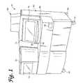
- FIG. 1is a perspective view of an automated nucleic acid-based diagnostic analyzer according to the present invention
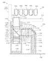
- FIG. 2is a perspective view of the structural frame of the analyzer of the present invention.
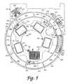
- FIG. 3is a plan view of a portion of the assay processing deck of the analyzer of the present invention.
- FIG. 4is an exploded perspective view of the assay processing deck
- FIG. 5is a plan view of a sample ring and a pipette tip wheel of the assay processing deck of the analyzer of the present invention
- FIG. 6is a perspective view showing the sample ring and the pipette tip wheel
- FIG. 6Ais a partial cross-sectional view along the line 6 A- 6 A in FIG. 5 ;
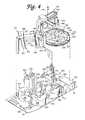
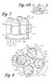
- FIG. 7is a perspective view of a multi-axis mixer of the processing deck of the analyzer of the present invention.
- FIG. 8is a plan view of the multi-axis mixer
- FIG. 9is a side elevation of the multi-axis mixer
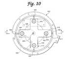
- FIG. 10is a plan view of the multi-axis mixer with container holders and a turntable cover removed therefrom;
- FIG. 11is a cross-sectional view of the multi-axis mixer taken in the direction 11 - 11 in FIG. 10 ;
- FIG. 12is a perspective view of a drive assembly of the multi-axis mixer
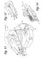
- FIG. 13is a perspective view of a transport mechanism of the processing deck of the analyzer of the present invention.
- FIG. 14is a perspective view of a manipulating hook mounting plate and a manipulating hook actuating mechanism of the transport mechanism, with the manipulating hook member engaged with a reaction receptacle and in a retracted position;
- FIG. 15is the same as FIG. 14 , except with the manipulating hook member in the extended position;
- FIG. 16is an exploded perspective view of the transport mechanism
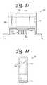
- FIG. 17is a side-elevation of a temperature ramping station of the processing deck of the analyzer of the present invention.
- FIG. 18is a front-elevation of the temperature ramping station
- FIG. 19is a perspective view of a rotary incubator of the processing deck of the analyzer of the present invention.
- FIG. 20is an exploded view of a portion of a housing and access opening closure mechanisms according to a first embodiment of the rotary incubator;
- FIG. 21is a partial view of a skewed disk linear mixer of the rotary incubator, shown engaged with a reaction receptacle employed in a preferred mode of operation of the analyzer of the present invention
- FIG. 22is an exploded perspective view of the first embodiment of the rotary incubator
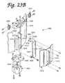
- FIG. 23is a perspective view of the rotary incubator according to a second embodiment thereof.
- FIG. 23Ais an exploded perspective view of the second embodiment of the rotary incubator
- FIG. 23Bis a partial exploded perspective view of an access opening closure mechanism of the second embodiment of the rotary incubator
- FIG. 23Cis an exploded view of a receptacle carrier carousel of the second embodiment of the rotary incubator
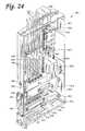
- FIG. 24is a perspective view of a particles of the processing deck of the present invention with a side plate thereof removed;
- FIG. 25is a partial transverse cross-section of the particles
- FIG. 25Ais a partial transverse cross-section of a tip of an aspirating tube of the particles with a contamination-limiting tiplet carried on the end thereof;
- FIG. 26is an exploded perspective view of a receptacle carrier unit, an orbital mixer assembly, and a divider plate of the particles;
- FIG. 27is a partial cross-sectional view of a wash solution dispenser nozzle, an aspirator tube with a contamination-limiting tiplet engaged with an end thereof, and a receptacle carrier unit of the particles, showing a multi-tube unit reaction receptacle employed in a preferred mode of operation of the analyzer carried in the receptacle carrier unit and the aspirator tube and contamination-limiting tiplet inserted into a reaction tube of the multi-tube unit;
- FIG. 28is a partial cross-sectional view of the wash solution dispenser nozzle, the aspirator tube, and the receptacle carrier unit of the particles, showing the multi-tube unit carried in the receptacle carrier unit and the aspirator tube engaging the contamination-limiting tiplet held in a contamination-limiting element holding structure of the multi-tube unit;
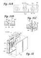
- FIGS. 29A-29Dshow a partial cross-section of a first embodiment of a tiplet stripping hole of a tiplet stripping plate of the particles and a tiplet stripping operation using the tiplet stripping hole;
- FIGS. 30A-30Dshow a partial cross-section of a second embodiment of a tiplet stripping hole and a tiplet stripping operation using the tiplet stripping hole;
- FIG. 31Ais a plan view of a third embodiment of a tiplet stripping hole of a tiplet stripping plate of the particles;
- FIGS. 31B-31Cshow a partial cross-section of the third embodiment of the tiplet stripping hole and a tiplet stripping operation using the tiplet;
- FIG. 32is a perspective view of an orbital mixer with a front plate thereof removed;
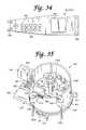
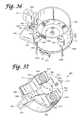
- FIG. 33is an exploded view of the orbital mixer of the processing deck of the analyzer of the present invention.
- FIG. 34is a top-plan view of the orbital mixer
- FIG. 35is a top perspective view of a reagent cooling bay of the processing deck of the analyzer of the present invention.
- FIG. 36is a top perspective view of a reagent cooling bay with the container tray removed therefrom;
- FIG. 37is a bottom plan view of the reagent cooling bay
- FIG. 38is an exploded view of the reagent cooling bay
- FIG. 39is a top perspective view of a modular container tray of the reagent cooling bay.
- FIG. 40is a perspective view of a first embodiment of a luminometer of the processing deck of the analyzer of the present invention.
- FIG. 41is a partial exploded perspective view of the luminometer of the first embodiment
- FIG. 42Ais a partial perspective view of a receptacle transport mechanism of the first embodiment of the luminometer
- FIG. 42Bis an end view of the receptacle transport mechanism of the first embodiment of the luminometer
- FIG. 42Cis a top view of the receptacle transport mechanism of the first embodiment of the luminometer
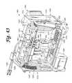
- FIG. 43is a break away perspective view of a second embodiment of the luminometer of the present invention.
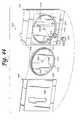
- FIG. 44is an exploded perspective view of a multi-tube unit door assembly for the luminometer of the second embodiment
- FIG. 45is an exploded perspective view of a shutter assembly for a photosensor aperture for the luminometer of the second embodiment
- FIG. 45Ais a perspective view of an aperture plate of the shutter assembly of the luminometer of the second embodiment
- FIG. 46is a perspective view of a reaction tube positioner assembly of the luminometer of the second embodiment, including a reaction tube positioner disposed within a reaction tube positioner frame;
- FIG. 47is a perspective view of the reaction tube positioner
- FIG. 48is a side elevation of the reaction tube positioner assembly
- FIG. 49is a perspective view showing the reaction tube positioner of the reaction tube positioner assembly operatively engaging a multi-tube unit employed in a preferred mode of operation of the analyzer;
- FIG. 50is a perspective view of a multi-tube unit transport mechanism of the luminometer of the second embodiment
- FIG. 51is a partial perspective view showing a multi-tube unit transport and drive screw of the multi-tube unit transport mechanism of the luminometer;
- FIG. 52is a perspective view of a lower chassis of the analyzer of the present invention.
- FIG. 53is a perspective view of a right-side drawer of the lower chassis
- FIG. 54is a perspective view of a left-side drawer of the lower chassis
- FIG. 55is a perspective view of a sample tube tray employed in a preferred mode of operation of the analyzer of the present invention.
- FIG. 56is a top plan view of the sample tube tray
- FIG. 57is a partial cross-section of the sample tube tray through line “ 57 - 57 ” in FIG. 55 ;
- FIG. 58is a perspective view of a multi-tube unit employed in a preferred mode of operation of the analyzer of the present invention.
- FIG. 59is a side elevation of a contact-limiting pipette tiplet employed in a preferred mode of operation of the analyzer of the present invention and carried on the multi-tube unit shown in FIG. 58 ;
- FIG. 60is an enlarged bottom view of a portion of the multi-tube unit, viewed in the direction of arrow “ 60 ” in FIG. 58 .
- FIG. 61is a side elevation in cross-section showing an optical detection module and portions of a real-time fluorometer and a multi-tube unit;
- FIG. 62is an exploded perspective view of the housing of the optical detection module
- FIG. 63is an exploded perspective view of the optical detection module
- FIG. 64is a top plan view of a real-time fluorometer showing preferred positions of the optical detection modules
- FIG. 65is a schematic view of a real-time fluorometer showing preferred positions of the optical detection modules
- FIG. 66is a graph showing excitation spectra of preferred amplification detection dyes
- FIG. 67is a graph showing emission spectra of preferred amplification detection dyes
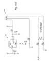
- FIGS. 68A-68Fshow a diagram of a circuit for the optical detection module
- FIG. 69is a perspective view showing the optical detector scanning assembly of a scanning real-time fluorometer
- FIG. 70is a side elevation of the detector scanning assembly
- FIG. 71is a top plan view of the detector scanning assembly
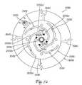
- FIG. 72is a bottom plan view of the detector scanning assembly.
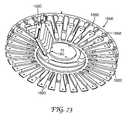
- FIG. 73is a perspective view of a portion of a carousel of the real-time fluorometer
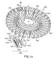
- FIG. 74is an exploded perspective view showing the carousel of the real-time fluorometer and a magnetic divider;
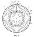
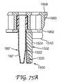
- FIG. 75is a bottom plan view of the carousel of the real-time fluorometer showing a single magnetic divider attached thereto;
- FIG. 75Ais a partial cross-sectional view taken along the line A-A in FIG. 75 ;
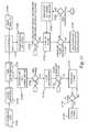
- FIG. 76Ais a flow chart showing the protocols of a preferred real-time amplification assay and a portion of a preferred end-point amplification assay which stops after exposure to amplification conditions, both assays being in accordance with the present invention
- FIG. 76Bis a flow chart showing the remainder of the protocol for the preferred end-point amplification assay of FIG. 76A following exposure to amplification conditions;
- FIG. 77is a flow chart showing an analyte quantification process
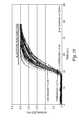
- FIG. 78is a time plot of real-time fluorometer data.
- FIG. 79is a plot showing a method for fitting a curve to real-time fluorometer data and using the fit to determine a threshold time.
- Analyzer 50includes a housing 60 built over an internal frame structure 62 , preferably made of steel.
- the analyzer 50is preferably supported on caster wheels 64 structurally mounted to the frame structure 62 so as to make the analyzer movable.
- the various stations involved in performing an automated assay and the assay samplesare housed within housing 60 .
- the various solutions, reagents, and other materials used in performing the assaysare preferably stored within the housing 60 , as are the waste products generated when assays are performed with the analyzer 50 .
- Housing 60includes a test receptacle loading opening 68 , which is shown in FIG. 1 to be disposed in a forwardly facing panel of the housing 60 , but could as well be located in other panels of the housing 60 .
- a pipette door 70 having a view window 72 and a carousel door 74 having a view window 76are disposed above a generally horizontal work surface 66 .
- a forwardly protruding arcuate panel 78accommodates a sample carousel, which will be described below.
- a flip-up arcuate sample door 80is pivotally attached to the housing so as to be vertically pivotal with respect to arcuate panel 78 so as to provide access to a forward portion of the sample carousel behind the panel 78 .
- the locking mechanism for each doorpreferably consists of a hook attached to a DC rotary solenoid (rated for continuous duty) with a spring return.
- Preferred rotary solenoidsare available from Lucas Control Systems, of Vandalia, Ohio, Model Nos. L-2670-034 and L-1094-034.
- An extension portion 102preferably made of a transparent or translucent material, extends above the top portion of housing 60 so as to provide vertical clearance for moving components within the housing 60 .
- the assaysare performed primarily on a processing deck 200 , which is the general location of the various assay stations of the analyzer 50 described below.
- the processing deck 200is shown in FIG. 2 without any of the assay stations mounted thereon.
- the processing deck 200comprises a datum plate 82 to which the various stations are directly or indirectly mounted.
- Datum plate 82preferably comprises a machined aluminum plate.
- the processing deck 200also known as the chemistry deck, separates the interior of the housing into the chemistry area, or upper chassis, above the datum plate 82 and the storage areas, or lower chassis 1100 , located below the datum plate 82 .
- a number of fans and louversare preferably provided in the upper chassis portion of the housing 60 to create air circulation throughout the upper chassis to avoid excessive temperatures in the upper chassis.
- the analyzer 50 of the present inventionis computer controlled
- the analyzer 50includes a computer controller, schematically represented as box 1000 in FIG. 2 , which runs high-level analyzer-controlling software known as the “assay manager program”.
- the assay manager programincludes a scheduler routine which monitors and controls test sample movement through the chemistry deck 200 .
- the computer controller 1000 which controls the analyzer 50may include a stand-alone computer system including a CPU, keyboard, monitor, and may optionally include a printer device.
- a portable cartmay also be provided for storing and supporting the various computer components.
- the computer hardware for running the analyzer-controlling softwaremay be integrally housed within the housing 60 of the analyzer 50 .
- Low level analyzer controlsuch as control of electric motors and heaters used throughout the analyzer 50 and monitoring of fluid levels within bulk fluid and waste fluid containers, is performed by an embedded controller, preferably comprising a Motorola 68332 microprocessor. Stepper motors used throughout the analyzer are also preferably controlled by preprogrammed, off-the-shelf, microprocessor chips available from E-M Technologies, Bala Cynwyd, Pa.
- FIG. 3represents a schematic plan view of a portion of the processing deck 200
- FIG. 4represents a schematic perspective view of the processing deck.
- the datum plate 82forms the foundation of the processing deck 200 on which all stations are directly or indirectly attached.
- Processing deck 200includes a reaction receptacle input queue 150 which extends from opening 68 in front of housing 60 .
- a plurality of reaction receptaclesare loaded in a stacked fashion in the input queue 150 .
- the purpose of the input queueis to hold a prescribed number of reaction receptacles and to sequentially present them at a pick-up position to be retrieved by a transport mechanism (described below).
- a reflective sensor at the pick-up positionverifies the presence of a receptacle at that position.
- the input queuealso includes a device for counting the number of receptacles resident therein at any given time.
- a reaction receptacle shuttle assemblywithin the queue moves the receptacles along a receptacle advance path toward the pick-up position.
- Optical sensorsindicate when the shuttle assembly is in its home and fully extended positions.
- the queueincludes a drawer which may be pulled out for loading the receptacles therein. Before the drawer is opened, however, it must be unlocked and the shuttle must disengage from the receptacle advance path. When the drawer is again closed, it is locked and the shuttle engages the receptacles and moves them toward the pick-up position.
- Optical sensorsindicate when the drawer is closed and when the shuttle has engaged a receptacle. As each receptacle is removed from the pick-up position by the transport mechanism, the receptacle shuttle advances the receptacles one receptacle-width, so that the next receptacle is in the pick-up position.
- reaction receptacles of the present inventionare preferably integrally formed linear arrays of reaction tubes known as multi-tube units or MTUs. These preferred reaction receptacles will be described in more detail below.
- a first ring assemblywhich in the preferred embodiment comprises a sample ring 250 , is mounted on a pivoting jig plate 130 at a distance above the datum plate 82 .
- Sample ring 250is generally circular and preferably holds up to nine sample trays 300 in an annular fluid container carrier portion thereof, and each of the sample trays preferably holds 20 sample-containing containers, or test tubes 320 .
- the sample ring 250is constructed and arranged to be rotatable about a first generally vertical axis of rotation and delivers the sample tubes 320 to a sample pipette assembly 450 , preferably an automated robotic pipette system.
- sample ring 250is accessible through the flip-up carousel door 80 provided in housing 60 so that trays 300 of test tubes 320 can be easily loaded onto the sample ring 250 and unloaded from the sample ring.
- Sample ring 250is driven by a motor, as will be described in more detail below.
- a second ring assemblywhich in the preferred embodiment comprises a pipette tip wheel 350 , is located in an interior portion of the sample ring 250 , so that at least a portion of the outer perimeter of the pipette tip wheel 350 is disposed radially inwardly of the inner periphery of the ring 250 .
- Pipette tip wheel 350carries thereon a plurality of commercially available packages of pipette tips.
- Pipette tip wheel 350is motor driven to rotate independently of sample ring 250 about a second axis of rotation that is generally parallel to the first axis of rotation of the sample ring 250 .
- the inner rotatable assemblyconstructed and arranged to carry a plurality of fluid containers is provided at an interior portion of the pipette tip wheel 350 .
- the inner rotatable assemblycomprises a multi-axis mixer 400 located radially inside the pipette tip wheel 350 (i.e., the second ring assembly) and sample ring 250 (i.e., the first ring assembly).
- the multi-axis mixer 400includes a rotating turntable 414 that is rotatable about a third axis of rotation that is generally parallel to the first and second axes of rotation and on which are mounted four independently and eccentrically rotating container holders 406 .
- Each of the container holders 406receives a container, preferably in the form of a plastic bottle, containing a fluid suspension of magnetic particles with immobilized polynucleotides and polynucleotide capture probes.
- Each container holder 406is generally cylindrical in shape and includes an axis of symmetry, or axis of rotation.
- the multi-axis mixer 400rotates each of the containers eccentrically with respect to the center of the holder 406 , while simultaneously rotating the turntable 414 about its center so as to provide substantially constant agitation of the containers to maintain the magnetic particles in suspension within the fluid.
- the sample pipette assembly, or robot, 450is mounted to the frame structure 62 (see FIG. 2 ) in a position above the sample ring 250 and pipette tip wheel 350 .
- the sample pipette assembly 450includes a pipette unit 456 having a tubular probe 457 mounted on a gantry assembly to provide X, Y, Z motion.
- the pipette unit 456is linearly movable in the Y-direction along a track 458 formed in a lateral rail 454
- the lateral rail 454is longitudinally movable in the X-direction along a longitudinal track 452 .
- the pipette unit 456provides vertical, or Z-axis motion of the probe 457 .
- Each axis of the sample pipette assembly 450is driven by a stepper motor in a known and conventional manner.
- the pipette assemblyis preferably an off-the-shelf product.
- Presently preferredis the Robotic Sample Processor, Model No. RSP9000, available from Cavro Inc. of Sunnyvale, Calif. This model includes a single gantry arm.
- the sample pipette assembly 450is preferably coupled to a syringe pump (not shown) (the Cavro XP 3000 has been used) and a DC driven diaphragm system fluid wash pump (not shown).
- the syringe pump of the sample pipette assembly 450is preferably mounted to the internal frame structure 62 within the housing 60 of the analyzer 50 at a position above the left-hand side of the chemistry deck 200 and is connected to pipette unit 456 by suitable tubing (not shown) or other conduit structures.
- a sample preparation opening 252is provided in the jig plate 130 , so that the sample pipette assembly 450 can access a reaction receptacle 160 in the input queue 150 located below the jig plate 130 .
- the sample pipette assembly 450 of the analyzer 50engages sample tubes 320 carried on the sample ring 250 through openings 140 , 142 of an elevated cover plate 138 and engages pipette tips carried on the pipette tip wheel 350 near the back portions of the sample ring 250 and pipette tip wheel 350 , respectively. Accordingly, an operator can have access to the forward portions of sample ring 250 and pipette tip wheel 350 through the carousel door opening 80 during operation of the analyzer without interfering with pipetting procedures.
- a tip wash/disposal station 340is disposed adjacent to the sample ring 250 on the jig plate 130 .
- Station 340includes a tip disposal tube 342 and a wash station basin 346 .
- the pipette unit 456 of the sample pipette assembly 450can move into position above the wash station basin 346 where the tubular probe 457 can be washed by pumping distilled water through the probe 457 , the basin of the wash station 346 being connected, preferably by a flexible hose (not shown), to a liquid waste container in the lower chassis 1100 .
- the tip disposal tube 342comprises an upstanding tubular member.
- an elongated pipette tipis frictionally secured onto the end of the tubular probe 457 of the pipette unit 456 , so that sample material does not come into contact with the tubular probe 457 of the pipette unit 456 when material is drawn from a sample tube 320 and into the elongated pipette tip.
- the pipette unit 456moves to a position above the tip disposal tube 342 and ejects the used, disposable pipette tip into the tip disposal tube 342 which is connected to one of the solid waste containers carried in the lower chassis 1100 .
- An elongated pipette tipis preferably also frictionally secured to the probe 457 for transferring target capture reagent from containers carried on the multi-axis mixer 400 to a reaction receptacle 160 . Following reagent transfer, the pipette tip is discarded.
- the sample ring 250 , the pipette tip wheel 350 , and the multi-axis mixer 400are preferably mounted on a hinged jig plate 130 (see FIGS. 5 and 6 ) supported above the datum plate 82 .
- the jig plate 130is hinged at a back end 132 thereof (see FIG. 6 ) so that the plate, and the ring 250 , the wheel 350 , and the mixer 400 mounted thereon, can be pivoted upwardly to permit access to the area of the chemistry deck below the jig plate.
- a first, or right-side, transport mechanism 500is mounted on the datum plate 82 below the jig plate 130 and sample ring 250 on generally the same plane as the input queue 150 .
- Transport mechanism 500includes a rotating main body portion 504 defining a receptacle carrier assembly and an extendible manipulating hook 506 mounted within the main body 504 and extendible and retractable with respect thereto by means of a powered hook member drive assembly.
- Each of the reaction receptacles 160preferably includes manipulating structure that can be engaged by the extendible manipulating hook 506 , so that the transport mechanism 500 can engage and manipulate a reaction receptacle 160 and move it from one location on the processing deck 200 to another as the reaction receptacle is sequentially moved from one station to another during the performance of an assay within the reaction receptacle 160 .
- a second, or left-side, transport mechanism 502of substantially identical construction as first transport mechanism 500 , is also included on the processing deck 200 .
- a plurality of receptacle parking stations 210are also located below the jig plate 130 .
- the parking stations 210are structures for holding sample-containing reaction receptacles until the assay performing stations of the processing deck 200 of the analyzer 50 are ready to accept the reaction receptacles.
- the reaction receptaclesare retrieved from and inserted into the parking stations 210 as necessary by the transport mechanism 500 .
- a right-side orbital mixer 550is attached to the datum plate 82 and receives reaction receptacles 160 inserted therein by the right-side transport mechanism 500 .
- the orbital mixeris provided to mix the contents of the reaction receptacle 160 .
- the right-side transport mechanism 500removes the reaction receptacle from the right-side orbital mixer 550 and moves it to another location in the processing deck.
- incubators 600 , 602 , 604 , 606of substantially identical construction are provided.
- Incubators 600 , 602 , 604 , and 606are preferably rotary incubators. Although the particular assay to be performed and the desired throughput will determine the desired number of necessary incubators, four incubators are preferably provided in the analyzer 50 .
- each incubator( 600 , 602 , 604 , 606 ) has a first, and may also have a second, receptacle access opening through which a transport mechanism 500 or 502 can insert a reaction receptacle 160 into the incubator or retrieve a reaction receptacle 160 from the incubator.
- a rotating receptacle carrier carouselwhich holds a plurality of reaction receptacles 160 within individual receptacle stations while the receptacles are being incubated.
- first rotary incubator TCis a TC incubator (also known as the “TC incubator”)
- second rotary incubator 602is an active temperature and pre-read cool-down incubator (also known as the “AT incubator”)
- third rotary incubator 604is an amplification incubator (also known as the “AMP incubator”)
- fourth rotary incubator 606is a hybridization incubator (also known as the “HYB incubator”).
- the names assigned to the incubatorsare for convenience only, signifying their uses in one preferred end-point amplification assay, and are not to be viewed as limiting other possible uses of these incubators).
- the construction, function, and role of the incubators in the overall performance of the assaywill be described in more detail below.
- the processing deck 200preferably also includes a plurality of temperature ramping stations 700 . Two such stations 700 are shown attached to the datum plate 82 between incubators 602 and 604 in FIG. 3 . Additional ramping stations may be disposed at other locations on the processing deck 200 where they will be accessible by one of the transport mechanisms 500 , 502 .
- a reaction receptacle 160may be placed into or removed from a temperature ramping station 700 by either transport mechanism 500 or 502 .
- Each ramping station 700either raises or lowers the temperature of the reaction receptacle and its contents to a desired temperature before the receptacle is placed into an incubator or another temperature sensitive station.
- the processing deck 200also includes magnetic separation stations 800 for performing a magnetic separation wash procedure.
- Each magnetic separation station 800can accommodate and perform a wash procedure on one reaction receptacle 160 at a time. Therefore, to achieve the desired throughput, five magnetic separation stations 800 working in parallel are preferred.
- Receptacles 160are inserted into and removed from the magnetic separation stations 800 by the left-side transport mechanism 502 .
- a reagent cooling bay 900is attached to the datum plate 82 roughly between the incubators 604 and 606 .
- Reagent cooling bay 900comprises a carousel structure having a plurality of container receptacles for holding bottles of temperature sensitive reagents.
- the carouselresides within a cooled housing structure having a lid with pipette-access holes formed therein.
- a second, or left-side, orbital mixer 552is disposed between incubators 606 and 604 .
- the left-side orbital mixer 552includes dispenser nozzles and lines for dispensing fluids into the reaction receptacle resident within the left-side orbital mixer 552 .
- a reagent pipette assembly, or robot, 470includes a double gantry structure attached to the frame structure 62 (see FIG. 2 ) and is disposed generally above the incubators 604 and 606 on the left-hand side of the processing deck 200 .
- reagent pipette assembly 470includes pipette units 480 and 482 .
- Pipette unit 480includes a tubular probe 481 and is mounted for linear movement, generally in the X-direction, along track 474 of lateral rail 476
- pipette unit 482including a tubular probe 483 , is also mounted for linear motion, generally in the X-direction, along track 484 of lateral rail 478 .
- Each pipette unit 480 , 482provides independent vertical, or Z-axis, motion of the respective probe 481 , 483 .
- Drive mechanisms within the assembly 470position the pipette units 480 , 482 to the correct X, Y, Z coordinates within the analyzer 50 to pipette fluids, to wash the tubular probes 481 , 483 of the respective pipette units 480 , 482 , or to stow the pipette units 480 , 482 during periods of nonuse, e.g., in “home” positions.
- Each axis of the pipette assembly 470is driven by a stepper motor.
- the reagent pipette assembly 470is preferably an off-the-shelf product.
- the presently preferred unitis the Cavro Robotic Sample Processor, Model No. RSP9000, with two gantry arms.
- the pipette units 480 , 482 of the reagent pipette assembly 470are each preferably coupled to a respective syringe pump (not shown) (the Cavro XP 3000 has been used) and a DC driven diaphragm system fluid wash pump.
- the syringe pumps of the reagent pipette assembly 470are preferably mounted to the internal frame structure 62 within the housing 60 of the analyzer 50 at a position above the left-hand side of the chemistry deck 200 and are connected to the respective pipette units 480 , 482 by suitable tubing (not shown) or other conduit structures.
- Each pipette unit 480 , 482preferably includes capacitive level sensing capability.
- Capacitive level sensingwhich is generally known in the medical instrumentation arts, employs capacitance changes when the dielectric of a capacitor, formed by the pipette unit as one plate of the capacitor and the structure and hardware surrounding a container engaged by the pipette unit as the opposite plate, changes from air to fluid to sense when the probe of the pipette unit has penetrated fluid within a container.
- the vertical position of the probe of the pipette unitwhich may be known by monitoring the stepper motor which drives vertical movement of the pipette unit, the level of the fluid within the container engaged by the pipette unit may be determined.
- Pipette unit 480transfers reagents from the reagent cooling bay 900 into reaction receptacles disposed within the HYB incubator 606 or the orbital mixer 552
- pipette unit 482transfers reagent materials from the reagent cooling bay 900 into reaction receptacles disposed within the AMP incubator 604 or the orbital mixer 552 .
- the pipette units 480 , 482use capacitive level sensing to ascertain fluid level within a container and submerge only a small portion of the end of the probe of the pipette unit to pipette fluid from the container. Pipette units 480 , 482 preferably descend as fluid is pipetted into the respective tubular probes 481 , 483 to keep the end of the probes submerged to a constant depth.
- the pipette unitsAfter drawing reagent into the tubular probe of the pipette unit 480 or 482 , the pipette units create a minimum travel air gap of 10 ⁇ l in the end of the respective probe 481 or 483 to ensure no drips from the end of the probe as the pipette unit is moved to another location above the chemistry deck 200 .
- the processing deck 200includes a luminometer 950 for detecting and/or quantifying the amount of light emitted by the contents of the reaction receptacle.
- the luminometer 950comprises a housing through which a reaction receptacle travels under the influence of a transport mechanism, a photomultiplier tube, and associated electronics. Various luminometer embodiments will be described in detail below.
- the processing deck 200also preferably includes a deactivation queue 750 .
- the assay performed in the analyzer 50involves the isolation and amplification of nucleic acids belonging to at least one organism or cell of interest. Therefore, it is desirable to deactivate the contents of the reaction receptacle 160 , typically by dispensing a bleach-based reagent into the reaction receptacle 160 at the conclusion of the assay. This deactivation occurs within the deactivation queue 750 .
- reaction receptacle 160Following deactivation, the deactivated contents of the reaction receptacle 160 are stored in one of the liquid waste containers of the lower chassis 1100 and the used reaction receptacle is discarded into a dedicated solid waste container within the lower chassis 1100 .
- the reaction receptacleis preferably not reused.
- the operation of the analyzer 50and the construction, cooperation, and interaction of the stations, components, and modules described above will be explained by describing the operation of the analyzer 50 on a single test sample in the performance of one type of assay which may be performed with analyzer 50 .
- Other diagnostic assayswhich require the use of one or more of the stations, components, and modules described herein, may also be performed with the analyzer 50 .
- the description herein of a particular assay procedureis merely for the purpose of illustrating the operation and interaction of the various stations, components, and modules of the analyzer 50 and is not intended to be limiting. Those skilled in the art of diagnostic testing will appreciate that a variety of chemical and biological assays can be performed in an automated fashion with the analyzer 50 of the present invention.
- the analyzer 50is initially configured for an assay run by loading bulk fluids into the bulk fluid storage bay of the lower chassis 1100 and connecting the bulk fluid containers to the appropriate hoses (not shown).
- the analyzeris preferably powered up in a sequential process, initially powering the stations, or modules, that will be needed early in the process, and subsequently powering the stations that will not be needed until later in the process. This serves to conserve energy and also avoids large power surges that would accompany full analyzer power-up and which could trip circuit breakers.
- the analyzeralso employs a “sleep” mode during periods of nonuse. During sleep mode, a minimal amount of power is supplied to the analyzer, again to avoid large surges necessary to power-up an analyzer from complete shut-down.
- reaction receptacles 160preferably in the form of plastic, integrally formed multiple-tube units (MTUs), which are described in more detail below, are loaded through opening 68 into the input queue 150 .
- MTUsmultiple-tube units
- the reaction receptacle shuttle assembly (not shown) within the input queue 150moves the MTUs 160 from the loading opening 68 to the pick-up position at the end of the queue 150 .
- the right-side transport mechanism 500takes an MTU 160 from the end of the queue 150 and moves to a bar code reader (not shown) to read the unique bar code label on that MTU which identifies that MTU. From the bar code reader, the MTU is moved to an available sample transfer station 255 below opening 252 .
- an MTU 160comprises a plurality of individual reaction tubes 162 , preferably five.
- the reaction tubes 162preferably in the form of cylindrical tubes with open top ends and closed bottom ends, are connected to one another by a connecting rib structure 164 which defines a downwardly facing shoulder extending longitudinally along either side of the MTU 160 .
- each reaction tube 162 of the MTU 160are 12 ⁇ 75 mm, although the analyzer 50 could be readily adapted to accommodate differently dimensioned reaction receptacles which are provided individually or as part of a multi-vessel reaction receptacle.
- the MTU 160is preferably formed from injection molded polypropylene.
- the most preferred polypropyleneis sold by Montell Polyolefins, of Wilmington, Del., product number PD701NW.
- the Montell materialis used because it is readily moldable, chemically compatible with the preferred mode of operation of the analyzer 50 , and has a limited number of static discharge events which can interfere with accurate detection or quantification of chemiluminescence.
- An arcuate shield structure 169is provided at one end of the MTU 160 .
- An MTU manipulating structure 166 to be engaged by one of the transport mechanisms 500 , 502extends from the shield structure 169 .
- MTU manipulating structure 166comprises a laterally extending plate 168 extending from shield structure 169 with a vertically extending piece 167 on the opposite end of the plate 168 .
- a gusset wall 165extends downwardly from lateral plate 168 between shield structure 169 and vertical piece 167 .
- the shield structure 169 and vertical piece 167have mutually facing convex surfaces.
- the MTU 160is engaged by the transport mechanisms 500 , 502 and other components, as will be described below, by moving an engaging member laterally (in the direction “A”) into the space between the shield structure 169 and the vertical piece 167 .
- the convex surfaces of the shield structure 169 and vertical piece 167provide for wider points of entry for an engaging member undergoing a lateral relative motion into the space.
- the convex surfaces of the vertical piece 167 and shield structure 169include raised portions 171 , 172 , respectively, formed at central portions thereof. The purpose of portions 171 , 172 will be described below.
- a label-receiving structure 174 having a flat label-receiving surface 175is provided on an end of the MTU 160 opposite the shield structure 169 and MTU manipulating structure 166 .
- Labelssuch as scannable bar codes, can be placed on the surface 175 to provide identifying and instructional information on the MTU 160 .
- the MTU 160preferably includes tiplet holding structures 176 adjacent the open mouth of each respective reaction tube 162 .
- Each tiplet holding structure 176provides a cylindrical orifice within which is received a contact-limiting tiplet 170 .
- the construction and function of the tiplet 170will be described below.
- Each holding structure 176is constructed and arranged to frictionally receive a tiplet 170 in a manner that prevents the tiplet 170 from falling out of the holding structure 176 when the MTU 160 is inverted, but permits the tiplet 170 to be removed from the holding structure 176 when engaged by a pipette.
- the tiplet 170comprises a generally cylindrical structure having a peripheral rim flange 177 and an upper collar 178 of generally larger diameter than a lower portion 179 of the tiplet 170 .
- the tiplet 170is preferably formed from conductive polypropylene.
- Hole 180includes an outwardly flared end 181 at the top of the tiplet 170 which facilitates insertion of a pipette tubular probe (not shown) into the tiplet 170 .
- Two annular ridges 183line the inner wall of hole 180 . Ridges 183 provide an interference friction fit between the tiplet 170 and a tubular probe inserted into the tiplet 170 .
- the bottom end of the tiplet 170preferably includes a beveled portion 182 .
- a beveled portion 182prevents a vacuum from forming between the end of the tiplet 170 and the bottom of the reaction reaction tube.
- the lower chassis 1100includes a steel frame 1101 with a black polyurethane powder coat, a pull-out drip tray 1102 disposed below the chassis, a right-side drawer 1104 , and a left-side drawer 1106 .
- the left-side drawer 1106is actually centrally disposed within the lower chassis 1100 .
- the far left-side of the lower chassis 1100houses various power supply system components and other analyzer mechanisms such as, for example, seven syringe pumps 1152 mounted on a mounting platform 1154 , a vacuum pump 1162 preferably mounted on the floor of the lower chassis 1100 on vibration isolators (not shown), a power supply unit 1156 , a power filter 1158 , and fans 1160 .
- various power supply system components and other analyzer mechanismssuch as, for example, seven syringe pumps 1152 mounted on a mounting platform 1154 , a vacuum pump 1162 preferably mounted on the floor of the lower chassis 1100 on vibration isolators (not shown), a power supply unit 1156 , a power filter 1158 , and fans 1160 .
- a different syringe pump 1152is designated for each of the five magnetic separation stations 800 , one is designated for the left-side orbital mixer 552 , and one is designated for the deactivation queue 750 .
- syringe pumpsare preferred, peristaltic pumps may be used as an alternative.
- the vacuum pump 1162services each of the magnetic separation stations 800 and the deactivation queue 750 .
- the preferred rating of the vacuum pumpis 5.3-6.5 cfm at 0′′ Hg and 4.2-5.2 cfm at 5′′ Hg.
- a preferred vacuum pumpis available from Thomas Industries, Inc. of Sheboygan, Wis., as Model No. 2750CGHI60.
- a capacitor 1172is sold in conjunction with the pump 1162 .
- the power supply unit 1156is preferably an ASTEC, Model No. VS1-B5-B7-03, available from ASTEC America, Inc., of Carlsbad, Calif. Power supply unit 1156 accepts 220 volts ranging from 50-60 Hz, i.e., power from a typical 220 volt wall outlet. Power filter 1158 is preferably a Corcom Model No. 20MV1 filter, available from Corcom, Inc. of Libertyville, Ill. Fans 1160 are preferably Whisper XLDC fans available from Comair Rotron, of San Ysidro, Calif. Each fan is powered by a 24 VDC motor and has a 75 cfm output. As shown in FIG.
- the fans 1160are preferably disposed proximate a left-side outer wall of the lower chassis 1100 .
- the fans 1160are preferably directed outwardly to draw air through the lower chassis from the right-side thereof to the left-side thereof, and thus, to draw excess heat out of the lower chassis.
- a power switch 1174preferably an Eaton circuit breaker switch 2-pole, series JA/S, available from the Cutler-Hammer Division of Eaton Corporation of Cleveland, Ohio, and a power inlet module 1176 at which a power cord (not shown) for connecting the analyzer 50 to an external power source is connected.
- the power supply system of the analyzer 50also includes a terminal block (not shown), for attaching thereto a plurality of electrical terminals, a solid state switch (not shown), which is preferably a Crydom Series 1, Model No. D2425, available from Cal Switch, Carson City, Calif., for switching between different circuits, and an RS232 9-pin connector port for connecting the analyzer 50 to the external computer controller 1000 .
- the right-side drawer and left-side drawer baysare preferably closed behind one or two doors (not shown) in front of the analyzer, which is/are preferably locked by the assay manager program during operation of the analyzer. Microswitches are preferably provided to verify door-closed status.
- the far left bayis covered by a front panel. End panels are provided on opposite ends of the lower chassis to enclose the chassis.
- the leveler feet 1180extend down from the four corners of the chassis 1100 .
- the leveler feet 1180include threaded shafts with pads at the lower ends thereof. When the analyzer is in a desired location, the feet 1180 can be lowered until the pads engage the floor to level and stabilize the analyzer. The feet can also be raised to permit the analyzer to be moved on its casters.
- Bulk fluids typically contained in the containers of the lower chassis 1100may include wash solution (for washing immobilized target), distilled water (for washing fixed pipette tips), diagnostic testing reagents, silicone oil (used as a floating fluid for layering over test reagents and sample), and a bleach-based reagent (used for sample deactivation).
- wash solutionfor washing immobilized target
- distilled waterfor washing fixed pipette tips
- diagnostic testing reagentsfor washing fixed pipette tips
- silicone oilused as a floating fluid for layering over test reagents and sample
- a bleach-based reagentused for sample deactivation
- the right-side drawer 1104is shown in detail in FIG. 53 .
- the right-side drawer 1104includes a box-like drawer structure with a front drawer handle 1105 .
- drawer handle 1105is shown as a conventional pull-type drawer handle, in the preferred embodiment of the analyzer 50 , handle 1105 is a T-handle latch, such as those available from Southco, Inc. of Concordville, Pa.
- the drawer 1104is mounted in the lower chassis on slide brackets (not shown) so that the drawer 1104 can be pulled into and out of the lower chassis.
- a sensor(not shown) is preferably provided for verifying that the drawer 1104 is closed.
- the front portion of the drawerincludes bottle receptacles 1122 for holding bottle 1128 (shown in FIG. 52 ), which is a dedicated pipette wash waste-containing bottle, and bottle 1130 (also shown in FIG. 52 ), which is a dedicated waste bottle for containing waste from a magnetic wash, target-capture procedure.
- Bottle 1130is preferably evacuated
- Bottle receptacles 1122preferably include bottle-present sensors (not shown) to verify the presence of a bottle in each receptacle 1122 .
- the bottle-present sensorsare preferably diffuse reflective type optical sensors available from SUNX/Ramco Electric, Inc., of West Des Moines, Iowa, Model No. EX-14A.
- Right-side drawer 1104further includes a waste bin 1108 for holding therein spent MTUs and sample tips.
- Waste bin 1108is an open box structure with a sensor mount 1112 at a top portion thereof for mounting thereon a sensor, preferably a 24VDC Opto-diffuse reflector switch (not shown), for detecting whether the waste bin 1108 is full.
- Another diffuse reflector type optical sensor(not shown) is positioned within right-side drawer 1104 to verify that the waste bin 1108 is in place.
- diffuse reflective type optical sensorsavailable from SUNX/Ramco Electric, Inc., of West Des Moines, Iowa, Model No. EX-14A, are preferred.
- a deflector 1110extends obliquely from a side of the waste bin 1108 .
- Deflector 1110is disposed directly below a chute through which spent MTUs are dropped into the waste bin 1108 and deflects the dropped MTUs toward the middle of the waste bin 1108 to avoid MTU pile-ups in a corner of the waste bin 1108 .
- Deflector 1110is preferably pivotally mounted so that it can pivot upwardly to a substantially vertical position so that when a waste bag, which lines the waste bin 1108 and covers the deflector 1110 , is removed from the waste bin 1108 , the deflector 1110 will pivot upwardly with the bag as it is pulled out and therefore will not rip the bag.
- a printed circuit board (not shown) and cover 1114can be mounted to the front of the waste bin 1108 .
- Sensor mounts 1116 and 1117are also mounted to the front of waste bin 1108 .
- Sensors 1118 and 1119are mounted on sensor mount 1116 , and sensors 1120 and 1121 mounted on sensor mount 1117 .
- Sensors 1118 , 1119 , 1120 , and 1121are preferably DC capacitive proximity sensors.
- the upper sensors 1118 , 1119indicate when the bottles 1128 and 1130 are full, and the bottom sensors 1120 , 1121 indicate when the bottles are empty.
- Sensors 1118 - 1121are preferably those available from Stedham Electronics Corporation of Reno, Nev., Model No. C2D45AN1-P, which were chosen because their relatively flat physical profile requires less space within the tight confines of the lower chassis 1100 and because the Stedham sensors provide the desired sensing distance range of 3-20 mm.
- the analyzer 50will preferably not begin performing any assays if the assay manager program detects that any of the waste fluid containers in the right-side drawer 1104 are not initially empty.
- the capacitive proximity sensors 1118 - 1121 and the bottle-present, waste-bin-present, and waste-bin-full optical sensors of the right-side drawer 1104are connected to the printed circuit board (not shown) behind cover 1114 , and the printed circuit board is connected to the embedded controller of the analyzer 50 .
- a handle 1126is mounted to the front of the waste bin 1108 and teflon strips 1124 are disposed on the bottom floor of the right-side drawer 1104 to facilitate forward and backward sliding of the waste bin 1108 in the drawer 1104 when bottles 1128 and 1130 are removed.
- Left-side drawer 1106includes a box-like structure with a front mounted handle 1107 and is mounted within the lower chassis 1100 on slide brackets (not shown).
- handle 1107is shown as a conventional pull-type drawer handle, in the preferred embodiment of the analyzer 50 , handle 1107 is a T-handle latch, such as those available from Southco, Inc. of Concordville, Pa.
- a sensoris provided for verifying that the left-side drawer 1106 is closed.
- Left-side drawer 1106includes a tiplet waste bin 1134 with a mounting structure 1135 for mounting thereon a tiplet-waste-bin-full sensor (not shown).
- a tiplet-waste-bin-present sensoris preferably provided in the left-side drawer 1106 to verify that the tiplet waste bin 1134 is properly installed.
- Diffuse reflective type optical sensorsavailable from SUNX/Ramco Electric, Inc., of West Des Moines, Iowa, Model No. EX-14A, are preferred for both the tiplet-waste-bin-full sensor and the tiplet-waste-bin-present sensor.
- Bundling structures 1132are provided for securing and bundling various tubing and/or wires (not shown) within the lower chassis 1100 .
- the bundling structures preferably usedare Energy Chain Systems manufactured and sold by Igus, Inc. of East Buffalo, R.I.
- a printed circuit board 1182is mounted behind a panel 1184 which is located behind the tiplet waste bin 1134 .
- a solenoid valve mounting panel 1186is located below the tiplet waste bin 1134 .
- Left-side drawer 1106includes a forward container-holding structure for holding therein six similarly sized bottles.
- the container structureincludes divider walls 1153 , 1155 , 1157 , and 1159 and container blocks 1151 having a curved bottle-conforming front edge, which together define six container-holding areas.
- Lower sensors 1148 and upper sensors 1150(six of each) are mounted on the divider walls 1155 , 1157 , and 1159 .
- the upper and lower sensors 1148 , 1150are preferably DC capacitive proximity sensors (preferably sensors available from Stedham Electronics Corporation of Reno, Nev., Model No. C2D45AN1-P, chosen for their flat profile and sensing range).
- the upper sensors 1150indicate when the bottles held in the container structure are full, and the lower sensors 1148 indicate when the bottles are empty.
- the left two bottles 1146contain a detecting agent (“Detect I”)
- the middle two bottles 1168contain silicon oil
- the right two bottles 1170contain another detecting agent (“Detect II”).
- Bottle-present sensorsare preferably provided in each of the container-holding areas defined by the container blocks 1151 and the dividing walls 1153 , 1155 , 1157 , and 1159 to verify the presence of bottles in each container-holding area.
- the bottle-present sensorsare preferably diffuse reflective type optical sensors available from SUNX/Ramco Electric, Inc., of West Des Moines, Iowa, Model No. EX-14A.
- a large centrally located container receptacle 1164holds a bottle 1140 (shown in FIG. 52 ), preferably containing deionized water.
- Container receptacles 1166(only one is visible in FIG. 54 ) hold bottles 1142 and 1144 (also shown in FIG. 52 ) preferably containing a wash solution.
- a dividing wall 1143 between the receptacle 1164 and 1166has mounted thereon sensors, such as sensor 1141 , for monitoring the fluid level in the bottles 1140 , 1142 , and 1144 .
- the sensors, such as sensor 1141are preferably DC capacitive proximity sensors (preferably sensors available from Stedham Electronics Corporation of Reno, Nev., Model No. C2D45AN1-P).
- Container receptacles 1164 and 1166preferably include bottle-present sensors (not shown) for verifying that bottles are properly positioned in their respective receptacles.
- the bottle-present sensorsare preferably diffuse reflective type optical sensors available from SUNX/Ramco Electric, Inc., of West Des Moines, Iowa, Model No. EX-14A.
- the analyzer 50will not begin performing any assays if the assay manager program determines that any of the bulk-fluid containers in the left-side drawer 1106 are initially empty.
- the capacitive proximity fluid level sensors, the various bottle-present sensors, the tiplet-waste-bin-full sensor, and the tiplet-waste-bin-present sensorsare all connected to the printed circuit board 1182 , and the printed circuit board 1182 is connected to the embedded controller of the analyzer 50 .
- solenoid valves(not shown) are mounted below the solenoid valve mounting panel 1186 .
- the solenoid valvesconnect bulk fluid bottles where fluids are stored in pairs of bottles, i.e., the bottles 1140 , 1142 containing wash solution, the two bottles 1146 containing the “Detect I” agent, the two bottles 1168 containing oil, and the two bottles 1170 containing the “Detect II” agent.
- the solenoid valvesin response to signals from the respective capacitive proximity sensors, switch bottles from which fluid is being drawing when one of the two bottles containing the same fluid is empty.
- the solenoid valvesmay switch bottles after a prescribed number of tests are performed.
- the preferred solenoid valvesare teflon solenoid valves available from Beco Manufacturing Co., Inc. of Madison Hills, Calif., Model Nos. S313W2DFRT and M223W2DFRLT.
- the two different model numberscorrespond to solenoid valves adapted for use with two different tube sizes. Teflon solenoid valves are preferred because they are less likely to contaminate fluids flowing through the valves and the valves are not damaged by corrosive fluids flowing through them.
- Bottle 1136(see FIG. 52 ) is a vacuum trap held in a vacuum trap bracket 1137 , and bottle 1138 contains a deactivating agent, such as bleach-containing reagent.
- a deactivating agentsuch as bleach-containing reagent.
- bottle-present sensorsare preferably provided to verify the presence of bottles 1136 and 1138 .
- a hand-held bar code scanner 1190may be provided in the lower chassis 1100 for scanning information provided on scannable container labels into the assay manager program.
- Scanner 1190is connected by a cord to printed circuit board 1182 of the left-side drawer 1106 and is preferably stowed on a bracket (not show) mounted on dividing wall 1143 .
- Scannersavailable from Symbol Technologies, Inc., of Holtsville, N.Y., series LS2100, are preferred.
- Samplesare contained in the sample tubes 320 , and the tubes 320 are loaded into the tube trays 300 outside the analyzer 50 .
- the trays 300 carrying the sample tubes 320are placed onto the sample ring 250 through the access opening provided by opening the flip-up carousel door 80 .
- the first ring assembly, or sample ring, 250is formed of milled, unhardened aluminum and includes a raised ring structure defining an annular trough 251 about the outer periphery of ring 250 with a plurality of raised, radially extending dividers 254 extending through trough 251 .
- nine dividers 254divide the trough 251 into nine arcuate sample tube tray-receiving wells 256 .
- the trough 251 and wells 256define an annular fluid container carrier portion constructed and arranged to carry a plurality of containers as will be described below.
- Sample ring 250is preferably rotationally supported by three 120°-spaced V-groove rollers 257 , 258 , 260 which engage a continuous V-ridge 262 formed on the inner periphery of ring 250 , as shown in FIGS. 5 , 6 , and 6 A so that the ring 250 is rotatable about a first central axis of rotation.
- the rollersare preferably made by Bishop-Wisecarver Corp. of Pittsburg, Calif., Model No. W1SSX.
- Rollers 257 and 260are rotationally mounted on fixed shafts, and roller 258 is mounted on a bracket which pivots about a vertical axis and is spring biased so as to urge roller 258 radially outward against the inner periphery of ring 250 . Having two fixed rollers and one radially movable roller allows the three rollers to accommodate an out-of-round inner periphery of the ring 250 .
- Sample ring 250is driven by stepper motor 264 (VEXTA stepper motors available from Oriental Motor Co., Ltd. of Tokyo, Japan as Model No. PK266-01A are preferred) via continuous belt 270 (preferably available from SDP/SI of New Hyde Park, N.Y., as Model No. A6R3M444080) which extends over guide rollers 266 , 268 and around the outer periphery of ring 250 .
- a home sensor and a sector sensor(not shown), preferably slotted optical sensors, are provided adjacent the ring 250 at a rotational home position and at a position corresponding to one of the sample tube tray receiving wells 256 .
- the ring 250includes a home flag (not shown) located at a home position on the wheel and nine equally-spaced sector flags (not shown) corresponding to the positions of each of the nine sample tube tray receiving wells 256 .
- the home flag and sector flagscooperate with the home sensor and sector sensors to provide ring position information to the assay manager program and to control the ring 250 to stop at nine discrete positions corresponding to established coordinates for user re-load and access by pipette unit 450 .
- Preferred sensors for the home sensor and sector sensorare Optek slotted optical sensors, Model No. OPB857, available from Optek of Carrollton, Tex.
- a sample coveris disposed over a portion of the annular fluid container carrier portion, or trough 251 , and comprises an arcuate cover plate 138 fixed in an elevated position with respect to the wheel 250 on three mounting posts 136 .
- Plate 138has an arcuate shape generally conforming to the curve of the trough 251 .
- a first opening 142is formed in the plate 138
- a second opening 140is formed in the plate 138 at a greater radial distance from the axis of rotation of ring 250 than opening 142 and at a circumferentially-spaced position from opening 142 .
- each sample tube tray 300comprises a test tube rack structure that is curved to conform to the curvature of the ring 250 .
- Each tray 300comprises a central wall structure 304 with lateral end walls 303 and 305 disposed on either end of wall 304 .
- a floor 312extends across the bottom of the tray 300 .
- the principle purposes of sample tube tray 300are to hold sample tubes on the sample ring 250 for access by the sample pipette assembly 450 and to facilitate loading and unloading of multiple sample tubes into and from the analyzer.
- a plurality of Y-shaped dividers 302are equidistantly spaced along opposite edges of the tray 300 . Each two adjacent dividers 302 define a test-tube receiving area 330 .
- End wall 303includes inwardly bent flanges 316 and 318
- end wall 305includes inwardly bent flanges 326 and 328 .
- the respective inwardly bent flanges of end walls 303 and 305 along with the end-most of the dividers 302define the end-most tube receiving areas 332 .
- the receiving areas 330 , 332are arcuately aligned along two arcuate rows on opposite sides of central wall structure 304
- a leaf spring element 310is attached to central wall 304 .
- Leaf spring element 310preferably formed of stainless spring steel, elastically deflects when a test tube 320 is inserted into the tube-receiving area 330 or 332 and urges the tube 320 outwardly against the dividers 302 .
- the tube 320is secured in an upright orientation.
- the shape of the dividers 302 and the elasticity of the leaf spring elements 310allow the tray 300 to accommodate sample tubes of various shapes and sizes, such as tubes 320 and 324 .
- Each tray 300preferably includes nine dividers 302 along each edge to form, along with end walls 303 and 305 , ten tube-receiving areas 330 , 332 on each side of central wall structure 304 for a total of twenty tube-receiving areas per tray.
- Indicia for designating tube-receiving areas 330 and 332such as raised numerals 306 , may be provided on the tray, such as on central wall 304 .
- Each tray 300may also include boss structures 308 , shown in the illustrated embodiment to be integrally formed with the end-most dividers 302 .
- An upright inverted U-shaped handle(not shown) may be attached to the tray at boss structures 308 or some other suitable location. Upright handles can facilitate handling of the tray 300 when loading and unloading the tray 300 through the arcuate carousel door 80 , but are not necessarily preferred.
- a gapis provided between adjacent dividers 302 so that bar-code labels 334 , or other readable or scannable information, on the tubes 320 is accessible when the tube is placed in the tray 300 .
- a tray 300 carried on wheel 250passes beneath the plate 138 of the sample cover, one tube 320 in a curved row at a radially-inward position with respect to wall structure 304 will be aligned with first opening 142 and another tube 320 in a curved row at a radially-outward position with respect to wall 304 will be aligned with second opening 140 .
- the ring 250is indexed to sequentially move each tube 320 beneath the openings 140 , 142 to permit access to the tubes.
- bar code scanners 272 and 274are disposed adjacent the ring 250 .
- Scanner 272is located outside ring 250
- scanner 274is disposed inside ring 250 .
- Scanners 272 and 274are positioned to scan bar code data labels on each sample tube 320 carried in the sample tube tray 300 as the ring 250 rotates a tray 300 of sample tubes 320 past the scanners 272 , 274 .
- the scanners 272 , 274scan the bar code label 337 (see FIG.
- each tray 300presents a special code 335 (see FIG. 55 ) to be read by the scanners 272 , 274 .
- a preferred sample tube holderis disclosed by Knight et al., “Sample Tube Holder,” U.S. Provisional Application No. 60/672,609, which enjoys common ownership herewith.
- Knightdiscloses sample tube holders having a plurality of sample tube compartments with aligned sets of finger springs for holding sample tubes in fixed, vertical orientations.
- the sample tube holdersinclude a retainer for maintaining sample tubes within the sample tube compartments during sampling procedures. See, e.g., Kacian et al., “Penetrable Cap,” U.S. Pat. No. 6,893,612 (discloses a sample tube closed with a cap having a frangible seal and a filter for limiting the dissemination of a contaminating aerosol or bubbles).
- a second ring assembly of the preferred embodimentis a pipette tip wheel 350 and comprises a circular ring 352 at a bottom portion thereof, a top panel 374 defining a circular inner periphery and five circumferentially-spaced, radially-protruding sections 370 , and a plurality of generally rectangular risers 354 separating the top panel 374 from the ring 352 and preferably held in place by mechanical fasteners 356 extending through the top panel 374 and ring 352 into the risers 354 .
- Top panel 374 , ring 352 , and risers 354are preferably made from machined aluminum, and boxes 376 are preferably formed from stainless steel sheet stock.
- the openings 358 and associated boxes 376are constructed and arranged to receive trays 372 holding a plurality of disposable pipette tips.
- the pipette tip trays 372are preferably those manufactured and sold by TECAN (TECAN U.S. Inc., Research Triangle Park, N.C.) under the trade name “Disposable Tips for GENESIS Series”. Each tip has a 1000 ⁇ l capacity and is conductive. Each tray holds ninety-six elongated disposable tips.
- Lateral slots 378 and longitudinal slots 380are formed in the top panel 374 along the lateral and longitudinal edges, respectively, of each opening 358 .
- the slots 378 , 380receive downwardly-extending flanges (not shown) disposed along the lateral and longitudinal edges of the trays 372 .
- the slots 378 , 380 and associated flanges of the trays 372serve to properly register the trays 372 with respect to openings 358 and to hold the trays 372 in place on the panel 374 .
- Pipette tip wheel 350is preferably rotationally supported by three 120°-spaced V-groove rollers 357 , 360 , 361 which engage a continuous V-ridge 362 formed on the inner periphery of ring 352 , as shown in FIGS. 5 , 6 , and 6 A, so that the pipette tip wheel 350 is rotatable about a second central axis of rotation that is generally parallel to the first axis of rotation of the sample ring 250 .
- the rollersare preferably made by Bishop-Wisecarver Corp. of Pittsburg, Calif., Model No. W1SSX.
- Rollers 357 and 360are rotationally mounted on fixed shafts, and roller 361 is mounted on a bracket which pivots about a vertical axis and is spring biased so as to urge roller 361 radially outwardly against the inner periphery of ring 352 .
- Having two fixed rollers and one radially movable rollerallows the three rollers to accommodate an out-of-round inner periphery of ring 352 .
- the wheel 350can be easily installed and removed by merely pushing pivoting roller 361 radially inwardly to allow the ring 352 to move laterally to disengage continuous V-ridge 362 from the fixed V-groove rollers 357 , 360 .
- Pipette tip wheel 350is driven by a motor 364 having a shaft-mounted spur gear which meshes with mating gear teeth formed on an outer perimeter of ring 352 .
- Motor 364is preferably a VEXTA gear head stepper motor, Model No. PK243-A1-SG7.2, having a 7.2:1 gear reduction and available from Oriental Motor Co., Ltd. of Tokyo, Japan.
- a gear head stepper motor with a 7.2:1 gear reductionis preferred because it provides smooth motion of the pipette tip wheel 350 , where the spur gear of the motor 364 is directly engaged with the ring 352 .
- a home sensor and a sector sensorare provided adjacent the pipette tip wheel 350 at a rotational home position and at a position of one of the boxes 376 .
- the pipette tip wheel 350includes a home flag (not shown) located at a home position on the wheel and five equally-spaced sector flags (not shown) corresponding to the positions of each of the five boxes 376 .
- the home flag and sector flagscooperate with the home sensor and sector sensors to provide wheel position information to the assay manager program and to control the pipette tip wheel 350 to stop at five discrete positions corresponding to established coordinates for user re-load and access by pipette unit 450 .
- Preferred sensors for the home sensor and sector sensorare Optek Technology, Inc. slotted optical sensors, Model No. OPB980, available from Optek Technology, Inc. of Carrollton, Tex.
- the multi-axis mixer 400includes a rotating turntable structure 414 (see FIG. 10 ) rotatably mounted on a center shaft 428 supported in center bearings 430 to a fixed base 402 mounted to the jig plate 130 by means of mechanical fasteners (not shown) extending through apertures 419 formed about the outer periphery of the fixed base 402 .
- a cover member 404is attached to and rotates with turntable 414 .
- Turntable 414is preferably in the form of a right angle cross comprising three 90°-spaced rectangular arms 444 of equal length extending radially outwardly from the center of the turntable 414 and a fourth arm 445 having an extension 417 making arm 445 slightly longer than arms 444 .
- the center portion of turntable 414is connected to center shaft 428 by a screw 429 .
- Each container holder 406is disposed on the ends of the arms 444 and 445 of turntable frame 414 .
- Each container holder 406is attached to one of four vertical shafts 423 , which are rotatably supported in container holder bearings 415 .
- Container holder bearings 415are pressed into the arms 444 , 445 of the turntable 414 and are disposed at equal radial distances from shaft 428 .
- the cover member 404includes four circular openings with upwardly-turned peripheral flanges 401 through which shafts 423 extend. Upward flanges 401 can advantageously prevent spilled liquids from flowing into the openings.
- the container holders 406comprise generally cylindrical members having an open bottom and an open top for receiving and holding a container 440 , preferably a plastic bottle, of target capture reagent.
- the target capture reagent used with the preferred assayincludes magnetically responsive particles with immobilized polynucleotides, polynucleotide capture probes, and reagents sufficient to lyse cells containing the targeted nucleic acids.
- targeted nucleic acidsare available for hybridization under a first set of predetermined hybridization conditions with one or more capture probes, with each capture probe having a nucleotide base sequence region which is capable of hybridizing to a nucleotide base sequence region contained in at least one of the targeted nucleic acids.
- a homopolymer tail (e.g., oligo(dT)) of the immobilized polynucleotidesis capable of hybridizing with a complementary homopolymer tail (e.g., oligo(dA)) contained in the capture probe, thereby immobilizing targeted nucleic acids.
- a complementary homopolymer taile.g., oligo(dA)
- target-capture methods and lysing proceduresare well known in the art and are readily adapted for use with the analyzer 50 of the present invention. This preferred two-step capture method of capturing and immobilizing a target nucleic acid on a magnetically responsive particle is disclosed by Weisburg et al. in U.S. Pat. No. 6,534,273.
- a container retainer spring 408spans a lateral slot formed in the wall of each container holder 406 and helps to hold the container 440 within the container holder 406 by urging the container 440 toward a portion of the inner peripheral wall of the holder 406 opposite the spring 408 .
- Each container holder 406is secured to an associated vertical shaft 423 by a shaft block structure 432 .
- Shaft block structure 432includes curved end portions which conform to the inside of the cylindrical container holder 406 , and the container holder 406 is secured to the block 432 by fasteners 434 .
- a generally circular aperture 449receives the shaft 423 .
- a slot 438extends from aperture 449 to an end of the block 432 which does not extend all the way to the inside of the container holder 406 , and a second slot 436 extends from an edge of the block 432 generally perpendicularly to slot 438 so as to define a cantilevered arm 435 .
- a machine screw 437extends through a through-hole 441 formed laterally through block 432 and into a threaded hole 447 formed laterally through arm 435 . As screw 437 is tightened, arm 435 deflects, thus tightening aperture 449 around shaft 423 .
- the shaft block structure 432 , the shaft 423 , and the container holder bearings 415 associated with each container holder 406define a preferred container holder mounting structure associated with each container holder 406 that is constructed and arranged to mount the container holder 406 to the turntable 414 and permit the container holder 406 to rotate about an axis of rotation 412 of the shaft 423 .
- Container holder planetary gears 422are attached to the opposite ends of shafts 423 .
- the planetary gears 422operatively engage a stationary sun gear 416 .
- a drive pulley 418is attached to center shaft 428 and is coupled to a drive motor 420 by a drive belt (not shown).
- Drive motor 420is preferably mounted so as to extend through an opening (not shown) in the jig plate 130 below the base 402 .
- Drive motor 420is preferably a stepper motor, and most preferably a VEXTA stepper motor, Model No. PK264-01A, available from Oriental Motor Co., Ltd. of Tokyo, Japan.
- the drive motor 420via the drive belt and drive pulley 418 , rotates the center shaft 428 and the turntable 414 attached thereto.
- the planetary gears 422 engaged with sun gear 416cause the shafts 423 and container holders 406 attached thereto to rotate at the ends of the arms 444 of the turntable frame 414 .
- Each container holder 406is preferably mounted such that the axis of rotation 410 thereof is offset from the axis of rotation 412 of the associated shaft 423 .
- each container holder 406rotates eccentrically about axis 412 of the associated shaft 423 .
- the planetary gears 422 and the sun gear 416constitute rotational motion coupling elements constructed and arranged to cause the container holders 406 to rotate about the respective axes of rotation of the shafts 423 as the turntable 414 rotates about the axis of rotation of the shaft 428 .
- a bar code scanner device 405is preferably mounted on a bracket 403 and reads bar code information of the containers 440 through a scanner slot 407 formed in each container holder 406 .
- the preferred scanneris a Model No. NFT1125/002RL scanner, available from Opticon, Inc. of Orangeburg, N.Y.
- the multi-axis mixer 400usually rotates during operation of the analyzer 50 to agitate the fluid contents of the containers 440 to thereby keep the target capture reagent in suspension, stopping only briefly to permit pipette unit 456 to withdraw an amount of mixture from one of the containers.
- Pipette unit 456draws mixture from a bottle at the same location each time. Therefore, it is desirable to monitor the positions of the bottles so that the bottle from which mixture is withdrawn each time can be specified.
- optical slotted sensors 426each comprising an optical emitter and detector, are stationed around the periphery of fixed base 402 , spaced at 900 intervals.
- Optical sensorsavailable from Optek Technology, Inc. of Carrollton, Tex., Model No. OPB490P11, are preferred.
- a sensor tab 424extends down from extension 417 at the end of arm 445 of the turntable 414 . When sensor tab 424 passes through a sensor 426 , the communication between the emitter and detector is broken thus giving a “container present” signal.
- the tab 424is only provided at one location, e.g., the first container location. By knowing the position of the first container, the positions of the remaining containers, which are fixed relative to the first container, are also known.
- Power and control signalsare provided to the multi-axis mixer 400 via a power and data connector. While the multi-axis mixer 400 provides mixing by rotation and eccentric revolution, other mixing techniques, such as vibration, inversion, etc. may be used.
- the pipette unit 456moves to transfer target capture reagent, preferably mag-oligo reagent, from a container 440 carried on the multi-axis mixer 400 into each of the reaction tubes 162 of the MTU 160 .
- the target capture reagentincludes a support material able to bind to and immobilize a target analyte.
- the support materialpreferably comprises magnetically responsive particles.
- the pipette unit 456 of the right-side pipette assembly 450moves laterally and longitudinally to a position in which the probe 457 is operatively positioned over a pipette tip in one of the trays 372 .
- the tip trays 372are carried on the pipette tip wheel 350 so as to be precisely positioned to achieve proper registration between the pipette tips and the tubular probe 457 of the pipette unit 456 .
- the pipette unit 456moves down to insert the free end of the tubular probe 457 into the open end of a pipette tip and frictionally engage the pipette tip.
- the Cavro processors preferably used for pipette unit 456includes a collar (not shown), which is unique to Cavro processors.
- This collaris moved slightly upwardly when a pipette tip is frictionally engaged onto the end of the tubular probe 457 , and the displaced collar trips an electrical switch on the pipette unit 456 to verify that a pipette tip is present. If tip pick-up is not successful (e.g., due to missing tips in the trays 372 or a misalignment), a missing tip signal is generated and the pipette unit 456 can move to re-try tip engagement at a different tip location.
- the assay manager programcauses the multi-axis mixer 400 to briefly stop rotating so that the pipette unit 456 can be moved to a position with the tubular probe 457 and attached pipette tip of the pipette unit 456 aligned over one of the stationary containers 440 .
- the pipette unit 456lowers the pipette tip attached to the tubular probe 457 into the container 440 and draws a desired amount of target capture reagent into the pipette tip.
- the pipette unit 456then moves the probe 457 out of the container 440 , the multi-axis mixer 400 resumes rotating, and the pipette unit 456 moves to a position above opening 252 and the sample transfer station 255 .
- the pipette unit 456descends, moving the pipette tip and the tubular probe 457 through the opening 252 , and dispenses a required amount of target capture (typically 100-500 ⁇ l) into one or more of the reaction tubes 162 of the MTU 160 . It is preferred that the target capture reagent is drawn only into the pipette tip and not into the probe 457 itself. Furthermore, it is preferred that the pipette tip be of sufficient volumetric capacity to hold enough reagent for all five reaction tubes 162 of the MTU 160 .
- the pipette unit 456After target capture reagent transfer, the pipette unit 456 then moves to a “tip discard” position above tip disposal tube 342 , where the disposable pipette tip is pushed or ejected off of the end of the tubular probe 457 of the pipette unit 456 , and falls through tube 342 toward a solid waste container.
- An optical sensor(not shown) is disposed adjacent to tube 342 , and before tip discard, the sample pipette assembly 450 moves the pipette unit 456 into a sensing position of the sensor.
- the sensordetects whether a tip is engaged with the end of the tubular probe 457 to verify that the tip is still held on the tubular probe 457 of the pipette unit 456 , thereby confirming that the tip was on the tubular probe 457 throughout sample preparation.
- a preferred sensoris a wide-gap slotted optic sensor, Model No. OPB900W, available from Optek Technology, Inc. of Carrollton, Tex.
- the pipette tipis ejected by the collar (not shown) on the tubular probe 457 of pipette unit 456 .
- the collarengages a hard stop when the tubular probe 457 is raised, so that as the probe 457 continues to ascend, the collar remains fixed and engages an upper end of the pipette tip, thereby forcing it off the tubular probe 457 .
- the probe 457 of the pipette unit 456can be washed by running distilled water through the tubular probe 457 at the tip wash station basin 346 .
- the tip wash wateris collected and drains down into a liquid waste container.
- the pipette unit 456 on the right pipette assembly 450moves laterally and longitudinally to a position in which the tubular probe 457 of the pipette unit 456 is centered over a new pipette tip on one of the tip trays 372 .
- the pipette unit 456moves back over the sample ring 250 , adjacent to the sample preparation opening 252 and withdraws a test sample (about 25-900 ⁇ l) from a sample tube 320 that is aligned with one of the openings 140 , 142 of the cover plate 138 .
- both openings 140 , 142include upwardly extending peripheral flanges to prevent any fluids spilled onto the plate 138 from running into the openings 140 , 142 .
- the pipette unit 456then moves over the MTU 160 in the sample transfer station 255 , moves down through opening 252 , and dispenses test sample into one of the reaction tubes 162 of the MTU 160 containing target capture reagent. Pipette unit 456 then moves to the “tip discard” position above the tip disposal tube 342 , and the disposable pipette tip is ejected into the tube 342 .
- Pipette unit 456then picks up a new disposable pipette tip from the pipette tip wheel 350 , the sample ring 250 indexes so that a new sample tube is accessible by the pipette unit 456 , unit 456 moves to and draws sample fluid from the sample tube into the disposable pipette tip, the pipette unit 456 then moves to a position above the sample transfer station 255 , and dispenses sample fluid into a different reaction tube 162 containing target capture reagent. This process is preferably repeated until all five reaction tubes 162 contain a combination of fluid sample and target capture reagent.
- the pipette unit 456may dispense the same test sample material into two or more of the reaction tubes 162 and the analyzer can perform the same or different assays on each of those aliquots.
- pipette unit 456also includes capacitive level sensing capability.
- the pipette tips used on the end of the tubular probe 457are preferably made from a conductive material, so that capacitive level sensing can be performed with the pipette unit 456 , even when a tip is carried on the end of the tubular probe 457 .
- the pipette unit 456moves the tubular probe 457 back down into the reaction tube 162 until the top of the fluid level is detected by the change in capacitance.
- the vertical position of the tubular probe 457is noted to determine whether the proper amount of fluid material is contained in the reaction tube 162 . Lack of sufficient material in a reaction tube 162 can be caused by clotting in the test sample, which can clot the tip at the end of the tubular probe 457 and prevent proper aspiration of test sample material into the tip and/or can prevent proper dispensing of test sample from the tip.
- the pipette tipis discarded into the tip disposal tube 342 as described above.
- the tubular probe 457 of the pipette of unitcan be washed with distilled water if desired, but washing of the probe is typically not necessary because, in the preferred method of operation, sample material only comes into contact with the disposable pipette tip.
- the assay manager programincludes pipette unit control logic which controls movements of the pipette units 456 , 480 , 482 , and preferably causes pipette unit 456 to move in such a manner that it never passes over a sample tube 320 on the sample ring 250 , except when the pipette unit 456 positions the tubular probe 457 over a sample tube 320 to withdraw a test sample or when the sample tube 320 is below the plate 138 of the sample cover. In this way, inadvertent fluid drips from the tubular probe 457 of the pipette unit 450 into another sample tube, which might result in cross-contamination, are avoided.
- the MTU 160is moved by the right-side transport mechanism 500 from the sample transfer station to the right orbital mixer 550 in which the sample/reagent mixtures are mixed.
- the structure and operation of the orbital mixers 550 , 552will be described in further detail below.
- the reaction receptacle shuttle assembly within the input queue 150advances the next MTU into a position to be retrieved by the right-side transport mechanism 500 which moves the next MTU to the sample transfer station. Sample preparation procedures are then repeated for this next MTU.
- the right-side transport mechanism 500(as well as the left-side transport mechanism 502 ) has a manipulating hook member that, in the illustrated embodiment, includes an extendible distributor hook 506 extending from a hook mounting structure 508 that is radially and slidably displaceable in a slot 510 on a plate 512 .
- a housing 504 on top of the plate 512has an opening 505 configured to receive the upper portion of an MTU 160 .
- a stepper motor 514 mounted on the plate 512turns a threaded shaft 516 , which, in cooperation with a lead screw mechanism, moves the distributor hook 506 from the extended position shown in FIGS.
- Stepper motor 514is preferably a modified HIS, series 46000.
- HIS stepper motorsare available from Haydon Switch and Instrument, Inc. of Waterbury, Conn.
- the HIS motoris modified by machining the threads off one end of the threaded shaft 516 , so that the shaft 516 can receive the hook mounting structure 508 .
- the housing 504 , motor 514 , and the plate 512are preferably covered by a conforming shroud 507 .
- a stepper motor 518turns a pulley 520 via a belt 519 .
- VEXTA stepper motorsModel No. PK264-01A, available from Oriental Motor Co., Ltd. of Tokyo, Japan
- SDP timing beltsModel No. A6R51 M200060, available from SDP/SI of New Hyde Park, N.Y.
- Pulley 520is preferably a custom-made pulley with one hundred sixty-two (162) axial grooves disposed around its perimeter.
- a main shaft 522 fixedly attached to the plate 512by means of a uniquely-shaped mounting block 523 , extends down through a base 524 and is fixed to the pulley 520 .
- Base 524is mounted to the datum plate 82 by means of mechanical fasteners extending through apertures 525 formed about the outer periphery of the base 524 .
- a flex circuit 526provides power and control signals to the hook mounting structure 508 and motor 514 , while allowing the plate 512 (and the components carried on the plate) to pivot sufficiently so as to rotate as much as 340° with respect to the base 524 .
- the transport mechanism 500 , 502 , assemblypreferably includes hard stops (not shown) at either end of the unit's rotational path of travel.
- An arm position encoder 531is preferably mounted on an end of the main shaft 522 .
- the arm position encoderis preferably an absolute encoder.
- the assay manager programprovides control signals to the motors 518 and 514 , and to the hook mounting structure 508 , to command the distributor hook 506 to engage the MTU manipulating structure 166 on MTU 160 .
- the motor 514can be energized to rotate the shaft 516 and thereby withdraw the hook 506 , and the MTU 160 , back into the housing 504 .
- the MTU 160is securely held by the transport mechanism 500 , 502 via the sliding engagement of the connecting rib structure 164 of the MTU 160 with opposed edges 511 of plate 512 adjacent slot 510 .
- the plate 512thereby constitutes an element of a preferred receptacle carrier assembly that is constructed and arranged to be rotatable about an axis of rotation (e.g., the axis of shaft 522 ) and to receive and carry a reaction receptacle (e.g., MTU 160 ).
- the motor 518can rotate the pulley 520 and shaft 522 via the belt 519 to thereby rotate the plate 512 and housing 504 with respect to the base 524 . Rotation of the housing 504 thus changes the orientation of the engaged MTU, thereby bringing that MTU into alignment with a different station on the processing deck.
- Sensors 528 , 532are provided in opposite sides of the housing 504 to indicate the position of the distributor hook 506 within the housing 504 .
- Sensor 528is an end-of-travel sensor
- sensor 532is a home sensor.
- Sensors 528 , 532are preferably optical slotted sensors available from Optek Technology, Inc. of Carrollton, Tex., Model No. OPB980T11.
- the sensor beamis broken by a home flag 536 extending from the hook mounting structure 508 when the hook 506 is in its fully retracted position.
- the beam of the end-of-travel sensor 528is broken by an end-of-travel flag 534 extending from the opposite side of the hook mounting structure 508 when the hook 506 is fully extended.
- An MTU-present sensor 530 mounted in the side of the housing 504senses the presence of an MTU 160 in the housing 504 .
- Sensor 530is preferably a SUNX, infra-red sensor, available from SUNX/Ramco Electric, Inc., of West Des Moines, Iowa.
- One or more temperature ramping stations 700are preferably disposed below the jig plate 130 and sample ring 250 (no temperature ramping stations located below the sample ring 250 are shown in the figures). After mixing the contents of the MTU 160 within the orbital mixer 550 , the right-side transport mechanism 500 may move the MTU 160 from the right orbital mixer 550 to a temperature ramping station 700 , depending on the assay protocol.
- each ramping station 700is to adjust the temperature of an MTU 160 and its contents up or down as desired.
- the temperature of the MTU and its contentsmay be adjusted to approximate an incubator temperature before inserting the MTU into the incubator to avoid large temperature fluctuations within the incubator.
- a temperature ramping station 700includes a housing 702 in which an MTU 160 can be inserted.
- the housing 702includes mounting flanges 712 , 714 for mounting the ramping station 700 to the datum plate 82 .
- a thermoelectric module 704also known as a Peltier device
- Preferred thermoelectric modulesare those available from Melcor, Inc. of Trenton, N.J., Model No. CP1.4-127-06L. Although one thermoelectric module 704 is shown in FIG. 17 , the ramping station 700 preferably includes two such thermoelectric modules.
- the outer surface of the housing 702could be covered with a mylar film resistive heating foil material (not shown) for heating the ramping station.
- Suitable mylar film heating foilsare etched foils available from Minco Products, Inc. of Minneapolis, Minn. and from Heatron, Inc. of Leavenworth, Kans.
- resistive heating elementsare preferably used, and for ramp-down stations (i.e., chillers), thermoelectric modules 704 are preferably used.
- the housing 702is preferably covered with a thermal insulating jacket structure (not shown).
- the heat sink structure used in conjunction with the thermoelectric module 704preferably comprises an aluminum block with heat dissipating fins 708 extending therefrom.
- Two thermal sensorsare preferably provided at a location on or within the housing 702 to monitor the temperature.
- YSI 44036 series thermistorsavailable from YSI, Inc. of Yellow Springs, Ohio are preferred.
- YSI thermistorsare preferred because of their high accuracy and the ⁇ 0.1° C. interchangeability provided by YSI thermistors from one thermistor to another.
- One of the thermal sensorsis for primary temperature control, that is, it sends signals to the embedded controller for controlling temperature within the ramping station, and the other thermal sensor is for monitoring ramping station temperature as a back-up check of the primary temperature control thermal sensor.
- the embedded controllermonitors the thermal sensors and controls the heating foils or the thermoelectric module of the ramping station to maintain a generally uniform, desired temperature within the ramping station 700 .
- An MTU 160can be inserted into the housing, supported on the MTU support flanges 718 which engage the connecting rib structure 164 of the MTU 160 .
- a cut-out 720is formed in a front edge of a side panel of the housing 702 .
- the cut-out 720permits a distributor hook 506 of a transport mechanism 500 or 502 to engage or disengage the MTU manipulating structure 166 of an MTU 160 inserted all the way into a temperature ramping station 700 by lateral movement with respect thereto.
- the right-side transport mechanism 500retrieves the MTU from the ramping station 700 and places the MTU 160 into the TC incubator 600 .
- the TC incubator 600incubates the contents of the MTU 160 at about 60° C.
- the annealing incubation temperaturenot vary more than ⁇ 0.5° C. and that amplification incubation (described below) temperature not vary more than ⁇ 0.1° C. Consequently, the incubators are designed to provide a consistent uniform temperature.
- each of the incubatorshas housing with a generally cylindrical portion 610 , suitably mounted to the datum plate 82 , within an insulating jacket 612 and an insulated cover 611 .
- the cylindrical portion 610is preferably constructed of nickel-plated cast aluminum and the metal portion of the cover 611 is preferably machined aluminum.
- the cylindrical portion 610is preferably mounted to the datum plate 82 atop three or more resin “feet” 609 .
- the feet 609are preferably formed of Ultem®- 1000 supplied by General Electric Plastics. The material is a poor thermal conductor, and therefore the feet 609 function to thermally isolate the incubator from the datum plate.
- the insulation 612 and the insulation for the cover 611are preferably comprised of 1 ⁇ 2 inch thick polyethylene supplied by the Boyd Corporation of Pleasantown, Calif.
- Receptacle access openings 614 , 616are formed in the cylindrical portion 610 , and cooperating receptacle access openings 618 , 620 are formed in the jacket 612 .
- one of the access openingsis positioned to be accessible by the right-side transport mechanism 500 and the other access opening is positioned to be accessible by the left-side transport mechanism 502 .
- Incubators 604 and 606need to be accessible only by the left-side transport mechanism 502 and therefore only have a single receptacle access opening.
- Closure mechanismscomprising revolving doors 622 , 624 are rotatably positioned within the openings 614 and 616 .
- Each revolving door 622 , 624has a MTU slot 626 extending through a solid cylindrical body.
- the MTU slot 626is configured to closely match the profile of the MTU 160 , having a wider upper portion compared to the lower portion.
- a door roller 628 , 630is attached on top of each of the doors 622 , 624 , respectively.
- the revolving doors 622 , 624are actuated by solenoids (not shown) which are controlled by commands from the assay manager program to open and close the doors 622 , 624 at the proper times.
- a door 622 or 624is opened by turning the door 622 , 624 so that the MTU slot 626 thereof is aligned with the respective receptacle access opening 614 , 616 and is closed by turning the door 622 , 624 so that the MTU slot 626 thereof extends transversely to the respective access opening 614 , 616 .
- the cylindrical portion 610 , cover 611 , doors 622 , 624 , and a floor panelconstitute an enclosure which defines the incubation chamber.
- the doors 622 , 624are opened to permit insertion or retrieval of an MTU into or from an incubator and are closed at all other times to minimize heat loss from the incubator through the access openings 614 , 616 .
- a centrally positioned radial fan 632is driven by an internal fan motor (not shown).
- a Papst, Model No. RER 100-25/14 centrifugal fan, available from ebm/Papst of Farmington, Conn., having a 24VDC motor and rated at 32 cfmis preferred because its shape is well-suited to application within the incubator.
- an MTU carousel assembly 671is a preferred receptacle carrier which carries a plurality of radially oriented, circumferentially-arranged MTUs 160 within the incubator.
- the MTU carousel assembly 671is carried by a top plate 642 , which is supported by the cylindrical portion 610 of the housing, and is preferably actuated by a rotation motor 640 , preferably a stepper motor, supported at a peripheral edge of on the top plate 642 .
- Rotation motor 640is preferably a VEXTA stepper motor, Model No. PK246-01A, available from Oriental Motor Co., Ltd. of Tokyo, Japan.
- the MTU carousel 671includes a hub 646 disposed below the top plate 642 and coupled, via a shaft 649 extending through the top plate 642 , to a pulley 644 .
- Pulley 644is preferably a custom-made pulley with one hundred sixty-two (162) axial grooves disposed around its perimeter and is coupled to motor 640 through a belt 643 , so that motor 640 can rotate the hub 646 .
- Belt 643is preferably a GT® series timing belt available from SDP/SI of New Hyde Park, N.Y.
- a 9:1 ratiois preferably provided between the pulley 644 and the motor 640 .
- the hub 646has a plurality of equally spaced-apart internal air flow slots 645 optionally separated by radially-oriented, circumferentially arranged divider walls 647 .
- divider walls 647are omitted.
- a support disk 670is attached to hub 646 and disposed below top plate 642 in generally parallel relation therewith.
- a plurality of radially extending, circumferentially-arranged MTU holding members 672are attached to the bottom of the support disk 670 (only three MTU holding members 672 are shown for clarity).
- the MTU holding members 672have support ridges 674 extending along opposite sides thereof.
- Radially oriented MTUsare carried on the MTU carousel assembly 671 within stations 676 defined by circumferentially adjacent MTU holding members 672 , with the support ridges 674 supporting the connecting rib structures 164 of each MTU 160 carried by the MTU carousel assembly 671 .
- the MTU carousel assemblyrotates on a carousel drive shaft to which the drive pulley ( 644 in the illustrated embodiment) is attached.
- a carousel position encoderis preferably mounted on an exterior end of the carousel drive shaft.
- the carousel position encoderpreferably comprises a slotted wheel and an optical slot switch combination (not shown).
- the slotted wheelcan be coupled to the carousel assembly 671 to rotate therewith, and the optical slot switch can be fixed to the cylindrical portion 610 of the housing or top plate 642 so as to be stationary.
- the slotted wheel/slot switch combinationcan be employed to indicate a rotational position of the carousel assembly 671 and can indicate a “home” position (e.g., a position in which an MTU station 676 designated the #1 station is in front of the access opening 614 ).
- A2 series encodersfrom U.S. Digital in Seattle, Wash., Model No. A2-S-K-315-H, are preferred.
- a heat sourceis provided in thermal communication with the incubator chamber defined within the incubator housing comprising the cylindrical portion 610 and cover 611 .
- Mylar film-encased electrically-resistive heating foils 660surround the housing 610 and may be attached to the cover 611 as well.
- Preferred mylar film heating foilsare etched foils available from Minco Products, Inc. of Minneapolis, Minn. and Heatron, Inc. of Leavenworth, Kans.
- Alternative heat sourcesmay include internally mounted resistive heating elements, thermal-electric heating chips (Peltiers), or a remote heat-generating mechanism thermally connected to the housing by a conduit or the like.
- a pipette slot 662extends through the incubator cover 611 , radially-aligned pipette holes 663 extend through the top plate 642 , and pipettes slots 664 are formed in the support disk 670 over each MTU station 676 , to allow pipetting of reagents into MTUs disposed within the incubators.
- only two of the incubatorsinclude the pipette holes 663 and pipette slots 662 and 664 , because, in the preferred mode of operation, it is only in these two incubators where fluids are dispensed into MTUs 160 while they are in the incubator.
- Two temperature sensors 666are positioned in the top plate 642 .
- YSI 44036 series thermistorsavailable from YSI, Inc. of Yellow Springs, Ohio are preferred. YSI thermistors are preferred because of their high accuracy and the ⁇ 0.1° C. interchangeability provided by YSI thermistors from one thermistor to another.
- One of the sensors 666is for primary temperature control, that is, it sends singles to the embedded controller for controlling temperature within the incubator, and the other sensor is for monitoring temperature of the incubator as a back-up check of the primary temperature control sensor.
- the embedded controllermonitors the sensors 666 and controls the heating foils 660 and fan 632 to maintain a uniform, desired temperature within the incubator housing 610 .
- the motor 640turns the hub 646 to bring an empty MTU station 676 into alignment with the receptacle access opening 614 (or 616 ).
- the door-actuating solenoidcorrespondingly turns the revolving door 622 (or 624 ) one-quarter turn to align the MTU slot 626 of the door with the MTU station 676 .
- the access opening 614is thus exposed to allow placement or removal of an MTU 160 .
- the transport mechanism 500 or 502then advances the distributor hook 506 from the retracted position to the extended position, pushing the MTU 160 out of the housing 504 , through the access opening 614 , and into an MTU station 676 in the incubator.
- the motor 640turns the hub 646 , shifting the previously inserted MTU 160 away from the access opening 614 , and the revolving door 622 closes once again. This sequence is repeated for subsequent MTUs inserted into the rotary incubator. Incubation of each loaded MTU continues as that MTU advances around the incubator (counter-clockwise) towards the exit slot 618 .
- An MTU sensorin each of the MTU stations 676 detects the presence of an MTU 160 within the station.
- Optek Technology, Inc. sensors, Model No. OPB770T, available from Optek Technology, Inc. of Carrollton, Tex.are preferred because of the ability of these sensors to withstand the high temperature environment of the incubators and because of the ability of these sensors to read bar code data fixed to the label-receiving surfaces 175 of the label-receiving structures 174 of the MTUs 160 .
- each door assemblypreferably includes slotted optical sensors (not shown) to indicate door open and door closed positions. Sensors available from Optek Technology, Inc.
- a skewed disk linear mixer(also known as a wobbler plate) 634 is provided within housing 610 adjacent MTU carousel assembly 671 and operates as a receptacle mixing mechanism.
- the mixer 634comprises a disk mounted in a skewed manner to the shaft of a motor 636 which extends through opening 635 into the housing 610 .
- the motoris preferably a VEXTA stepper motor, Model No. PK264-01A, available from Oriental Motors Ltd. of Tokyo, Japan, which is the same motor preferably used for the MTU carousel assembly 671 .
- a viscous harmonic damper 638is preferably attached to motor 636 to damp out harmonic frequencies of the motor which can cause the motor to stall.
- Preferred harmonic dampersare VEXTA harmonic dampers, available from Oriental Motors Ltd. The operation of the skewed disk linear mixer 634 will be described below.
- the AMP incubator 604 and the HYB incubator 606include a skewed disk linear mixer 634 , because, in the preferred mode of operation, it is only in these two incubators where fluids are dispensed into the MTUs 160 while they are in the incubator. Thus, it is only necessary to provide linear mixing of the MTU 160 by the skewed disk linear mixer 634 in the AMP incubator 604 and the HYB incubator 606 .
- the MTU carousel assembly 671moves the MTU 160 into alignment with the skewed disk linear mixer 634 , and the skewed disk of the skewed disk linear mixer 634 engages the MTU manipulating structure 166 of the MTU 160 .
- the motor 636spins the skewed disk of the skewed disk linear mixer 634 , the portion of the skewed disk structure engaged with the MTU 160 moves radially in and out with respect to the wall of the housing 610 , thus alternately engaging the vertical piece 167 of the MTU manipulating structure 166 and the shield structure 169 .
- the MTU 160 engaged with the skewed disk linear mixer 634is moved radially in and out, preferably at high frequency, providing linear mixing of the contents of the MTU 160 .
- a mixing frequency of 10 Hzis preferred.
- a mixing frequency of 14 Hzis preferred.
- a mixing frequency of 13 Hzis preferred.
- the raised arcuate portions 171 , 172may be provided in the middle of the convex surfaces of the vertical piece 167 and the shield structure 169 of the MTU 160 , respectively, (see FIG. 60 ) to minimize the surface contact between the skewed disk linear mixer 634 and the MTU 160 so as to minimize friction between the MTU 160 and the skewed disk linear mixer 634 .
- a sensoris provided at the skewed disk linear mixer 634 to ensure that the skewed disk linear mixer 634 stops rotating in the “home” position shown in FIG. 21 , so that MTU manipulating structure 166 can engage and disengage from the skewed disk linear mixer 634 as the MTU carousel assembly 671 rotates.
- the preferred “home” sensoris a pin extending laterally from the skewed disk linear mixer structure and a slotted optical switch which verifies orientation of the skewed disk linear mixer assembly when the pin interrupts the optical switch beam. Hall effect sensors based on magnetism may also be used.
- the alternate incubatorincludes a housing assembly 1650 generally comprising a cylindrical portion 1610 constructed of nickel-plated cast aluminum, a cover 1676 preferably formed of machined aluminum, insulation 1678 for the cover 1676 , and an insulation jacket 1651 surrounding the cylindrical portion 1610 .
- the incubatormay include a linear mixer mechanism including a linear mixer motor 636 with a harmonic damper 638 .
- a closure mechanism 1600(described below) operates to close off or permit access through a receptacle access opening 1614 .
- the incubatormay include one or two access openings 1614 depending on the location of the incubator and its function within the analyzer 50 .
- a centrifugal fan 632is mounted at a bottom portion of the housing 1650 and is driven by a motor (not shown).
- a fan cover 1652is disposed over the fan and includes sufficient openings to permit air flow generated by the fan 632 .
- a carousel support shaft 1654includes a lower shaft 1692 and an upper shaft 1690 divided by a support disk 1694 . The support shaft 1654 is supported by means of the lower shaft 1692 extending down into the fan cover 1652 where it is rotatably supported and secured by bearings (not shown).
- An MTU carousel 1656includes an upper disk 1658 having a central portion 1696 .
- a top surface of the support disk 1694engages and is attached to a bottom surface of the central portion 1696 of the upper disk 1658 so that the weight of the carousel 1656 is supported from below.
- a plurality of radially extending, circumferentially spaced station dividers 1660are attached beneath the upper disk 1658 .
- a lower disk 1662includes a plurality of radial flanges 1682 emanating from an annular inner portion 1688 .
- the radial flanges 1682correspond in number and spacing to the carousel station dividers 1660 , and the lower disk 1662 is secured to the bottom surfaces of the carousel station dividers 1660 , with each flange 1682 being secured to an associated one of the dividers 1660 .
- the radial flanges 1682define a plurality of radial slots 1680 between adjacent pairs of flanges 1682 .
- the width in the circumferential direction of each flange 1682 at an inner end 1686 thereofis less than the width in the circumferential direction of the flange 1682 at the outer end 1684 thereof.
- the tapered shape of the flanges 1682ensures that the opposite sides of the slots 1680 are generally parallel to one another.
- the widths of the flanges along at least a portion of their respective lengthsare greater than the widths of the respective dividers 1660 , which may also be tapered from an outer end thereof toward an inner end thereof.
- the flanges 1684define lateral shelves along the sides of adjacent pairs of dividers 1660 for supporting the connecting rib structure 164 of an MTU 160 inserted into each MTU station 1663 defined between adjacent pairs of dividers 1660 .
- a pulley 1664is secured to the top of the central portion 1696 of the upper disk 1658 and a motor 1672 is carried by a mounting bracket 1670 which spans the diameter of the housing and is secured to the cylindrical portion 1610 of the housing at opposite ends thereof.
- the motoris preferably a Vexta PK264-01A stepper motor, and it is coupled to the pulley (having a 9:1 ratio with respect to the motor) by a belt 1666 , preferably one supplied by the Gates Rubber Company.
- a position encoder 1674is secured to a top central portion of the mounting bracket 1672 and is coupled with the upper shaft 1690 of the carousel support shaft 1654 .
- the encoder 1674(preferably an absolute encoder of the A2 series by U.S. Digital Corporation of Vancouver, Wash.) indicates the rotational position of the carousel 1656 .
- An incubator coveris defined by an incubator plate 1676 , preferably formed of machined aluminum, and a conforming cover insulation element 1678 .
- Cover plate 1676 and insulation element 1678include appropriate openings to accommodate the encoder 1674 and the motor 1672 and may also include radial slots formed therein for dispensing fluids into MTUs carried within the incubator as described with regard to the above embodiment.
- FIG. 23BAn alternate, and preferred, closure mechanism 1600 is shown in FIG. 23B .
- the cylindrical portion 1610 of the incubator housingincludes at least one receptacle access opening 1614 with outwardly projecting wall portions 1616 , 1618 extending integrally from the cylindrical portion 1610 along opposite sides of the access opening 1614 .
- a rotating door 1620is operatively mounted with respect to the access opening 1614 by means of a door mounting bracket 1636 attached to the cylindrical portion 1610 of the housing above the access opening 1614 .
- Door 1620includes an arcuate closure panel 1622 and a transversely extending hinge plate portion 1628 having a hole 1634 for receiving a mounting post (not shown) of the door mounting bracket 1636 .
- the door 1622is rotatable about the opening 1634 with respect to the access opening 1614 between a first position in which the arcuate closure panel 1622 cooperates with the projecting wall portions 1616 , 1618 to close off the access opening 1614 and a second position rotated outwardly with respect to the access opening 1614 to permit movement of a receptacle through the access opening 1614 .
- An inner arcuate surface of the arcuate panel 1622conforms with an arcuate surface 1638 of the door mounting bracket 1636 and an arcuate surface 1619 disposed below the receptacle access opening 1614 to permit movement of the arcuate panel 1622 with respect to the surfaces 1638 and 1619 while providing a minimum gap between the respective surfaces so as to minimize heat loss therethrough.
- the door 1620is actuated by a motor 1642 mounted to the incubator housing by means of a motor mounting bracket 1640 secured to the cylindrical portion 1610 of the housing beneath the receptacle access opening 1614 .
- a motor shaft 1644is coupled to a lower actuating plate 1626 of the rotating door 1620 so that rotation of the shaft 1644 is transmitted into rotation of the rotating door 1620 .
- Motor 1642is most preferably an HIS 7.5° per step motor available from Haydon Switch and Instrument, Inc. of Waterbury, Conn. The HIS motor is chosen because of its relatively low cost and because the closure assembly 1600 does not require a high torque, robust motor.
- Door position sensors 1646 and 1648are operatively mounted on opposite sides of the door mounting bracket 1636 .
- the sensor 1646 and 1648cooperate with sensor tabs 1632 and 1630 on the hinge plate 1628 of the door 1620 for indicating the relative position of the rotating door 1620 and can be configured so as to indicate, for example, a door open and a door closed status.
- a door cover element 1612is secured to the outside of the cylindrical portion 1610 of the housing so as to cover the door mounting bracket 1636 and a portion of the rotating door 1620 .
- the cover element 1612includes an access opening 1613 aligned with the access opening 1614 of the incubator housing and further includes a receptacle bridge 1615 extending laterally from a bottom edge of the access opening 1613 .
- the receptacle bridge 1615facilitates the insertion of a receptacle (e.g., an MTU 160 ) into and withdrawal of the receptacle from the incubator.
- the MTU 160 and test samplesare preferably kept at a temperature of about 60° C. ⁇ 0.5° C. for a period of time sufficient to permit hybridization between capture probes and target nucleic acids. Under these conditions, the capture probes will preferably not hybridize with those polynucleotides directly immobilized on the magnetic particles.
- the MTU 160is rotated by the incubator carousel to the entrance door 622 , also known as the right-side or number one distributor door.
- the MTU 160is retrieved from its MTU station 676 within the TC incubator 600 and is then transferred by the right-side transport mechanism 500 to a temperature ramp-down station (not shown) below the sample ring 250 .
- a temperature ramp-down station(not shown) below the sample ring 250 .
- the MTU temperatureis brought down to the level of the next incubator.
- This ramp-down station that precedes the AT incubator 602is technically a heater, as opposed to a chiller, because the temperature to which the MTU is decreased, about 40° C., is still greater than the ambient analyzer temperature, about 30° C. Accordingly, this ramp-down station preferably uses resistive heating elements, as opposed to a thermoelectric module.
- the MTU 160is transferred by the right-side transfer mechanism 500 into the AT incubator 602 .
- the design and operation of the AT incubator 602is similar to that of the TC incubator 600 , as described above, except that the AT incubator 602 incubates at 40 ⁇ 1.0° C.
- the hybridization conditionsare such that the polythymidine (“poly(dT)”) tail of the immobilized polynucleotide can hybridize to the polyadenine (“poly(dA)”) tail of the capture probe.
- poly(dT)polythymidine
- poly(dA)polyadenine
- a hybridization complexcan be formed between the immobilized polynucleotide, the capture probe and the target nucleic acid in the AT incubator 602 , thus immobilizing the target nucleic acid.
- the carousel assembly 1656 (or 671 ) of the AT incubator 602rotates the MTU to the exit door 624 , also known as the number two, or left-side, distributor door, from which the MTU 160 can be removed by the left-side transport mechanism 502 .
- the left-side transport mechanism 502removes the MTU 160 from the AT incubator 602 and places it into an available magnetic separation station 800 .
- Temperature ramping stations 700can be a bottle neck in the processing of a number of MTUs through the chemistry deck 200 . It may be possible to use underutilized MTU stations 676 in one or more of the incubators in which temperature sensitivity is of less concern. For example, the active temperature binding process which occurs within the AT incubator 602 at about 40° C. is not as temperature sensitive as the other incubators, and up to fifteen (15) of the incubator's thirty (30) MTU stations 676 may be unused at any given time. As presently contemplated, the chemistry deck has only about eight ramp-up stations, or heaters.
- each magnetic separation station 800includes a module housing 802 having an upper section 801 and a lower section 803 .
- Mounting flanges 805 , 806extend from the lower section 803 for mounting the magnetic separation stations 800 to the datum plate 82 by means of suitable mechanical fasteners.
- Locator pins 807 and 811extend from the bottom of lower section 803 of housing 802 . Pins 807 and 811 register with apertures (not shown) formed in the datum plate 82 to help to locate the magnetic separation stations 800 on the datum plate 82 before the housing 802 is secured by fasteners.
- a loading slot 804extends through the front wall of the lower section 803 to allow a transport mechanism (e.g. 502 ) to place an MTU 160 into and remove an MTU 160 from the magnetic separation station 800 .
- a tapered slot extension 821surrounds a portion of the loading slot 804 to facilitate MTU insertion through the slot 804 .
- a divider 808separates the upper section 801 from the lower section 803 .
- a pivoting magnet moving structure 810is attached inside the lower section 803 so as to be pivotable about point 812 .
- the magnet moving structure 810carries permanent magnets 814 , which are positioned on either side of an MTU slot 815 formed in the magnet moving structure 810 .
- the magnetsare preferably made of neodymium-iron-boron (NdFeB), minimum grade ⁇ 35 and have preferred dimensions of 0.5 inch width, 0.3 inch height, and 0.3 inch depth.
- actuator 816pivots the magnet moving structure 810 up and down, thereby moving the magnets 814 .
- actuator 816preferably comprises a rotary stepper motor 819 which rotates a drive screw mechanism coupled to the magnet moving structure 810 to selectively raise and lower the magnet moving structure 810 .
- Motor 819is preferably an HIS linear stepper actuator, Model No. 26841-05, available from Haydon Switch and Instrument, Inc. of Waterbury, Conn.
- a sensor 818preferably an optical slotted sensor, is positioned inside the lower section 803 of the housing for indicating the down, or “home”, position of the magnet moving structure 810 .
- Sensor 818is preferably an Optek Technology, Inc., Model No. OPB980T11, available from Optek Technology, Inc. of Carrollton, Tex.
- Another sensor 817also preferably an Optek Technology, Inc., Model No. OPB980T11, optical slotted sensor, is preferably provided to indicate the up, or engaged, position of the magnet moving structure 810 .
- An MTU carrier unit 820is disposed adjacent the loading slot 804 , below the divider 808 , for operatively supporting an MTU 160 disposed within the magnetic separation stations 800 .
- the MTU carrier unit 820has a slot 822 for receiving the upper end of an MTU 160 .
- a lower fork plate 824attaches to the bottom of the carrier unit 820 and supports the underside of the connecting rib structure 164 of the MTU 160 when slid into the carrier unit 820 (see FIGS. 27 and 28 ).
- a spring clip 826is attached to the carrier unit 820 with its opposed prongs 831 , 833 extending into the slot 822 to releasably hold the MTU within the carrier unit 820 .
- An orbital mixer assembly 828is coupled to the carrier unit 820 for orbitally mixing the contents of an MTU held by the MTU carrier unit 820 .
- the orbital mixer assembly 828includes a stepper motor 830 mounted on a motor mounting plate 832 , a drive pulley 834 having an eccentric pin 836 , an idler pulley 838 having an eccentric pin 840 , and a belt 835 connecting drive pulley 834 with idler pulley 838 .
- Stepper motor 830is preferably a VEXTA, Model No. PK245-02A, available from Oriental Motors Ltd. of Tokyo, Japan, and belt 835 is preferably a timing belt, Model No.
- eccentric pin 836fits within a slot 842 formed longitudinally in the MTU carrier unit 820 .
- Eccentric pin 840fits within a circular aperture 844 formed in the opposite end of MTU carrier unit 820 .
- the motor 830turns the drive pulley 834
- idler pulley 838also rotates via belt 835 and the MTU carrier unit 820 is moved in a horizontal orbital path by the eccentric pins 836 , 840 engaged with the apertures 842 , 844 , respectively, formed in the carrier unit 820 .
- the rotation shaft 839 of the idler pulley 838preferably extends upwardly and has a transverse slot 841 formed therethrough.
- An optical slotted sensor 843is disposed at the same level as the slot 841 and measures the frequency of the idler pulley 838 via the sensor beam intermittently directed through slot 841 as the shaft 839 rotates.
- Sensor 843is preferably an Optek Technology, Inc., Model No. OPB980T11, sensor, available from Optek Technology, Inc. of Carrollton, Tex.
- Locator plate 846passes through slotted optical sensors 847 , 848 mounted to a sensor mounting bracket 845 extending from motor mounting plate 832 .
- Sensors 847 , 848are preferably Optek Technology, Inc., Model No. OPB980T11, sensors, available from Optek Technology, Inc. of Carrollton, Tex.
- Locator plate 846has a plurality of circumferentially spaced axial openings formed therein which register with one or both sensors 847 , 848 to indicate a position of the orbital mixer assembly 828 , and thus a position of the MTU carrier unit 820 .
- wash solution delivery tubes 854connect to fittings 856 and extend through a top surface of the module housing 802 . Wash solution delivery tubes 854 extend through the divider 808 via fittings 856 , to form a wash solution delivery network.
- wash solution dispenser nozzles 858extending from the fittings 856 are disposed within the divider 808 .
- Each nozzleis located above a respective reaction tube 162 of the MTU 160 at a laterally off-center position with respect to the reaction tube 162 .
- Each nozzleincludes a laterally-directed lower portion 859 for directing the wash solution into the respective reaction tube from the off-center position. Dispensing fluids into the reaction tubes 162 in a direction having a lateral component can limit splashing as the fluid runs down the sides of the respective reaction tubes 162 .
- the laterally directed fluidcan rinse away materials clinging to the sides of the respective reaction tubes 162 .
- aspirator tubes 860extend through a tube holder 862 , to which the tubes 860 are fixedly secured, and extend through openings 861 in the divider 808 .
- a tube guide yoke 809(see FIG. 26 ) is attached by mechanical fasteners to the side of divider 808 , below openings 861 .
- Aspirator hoses 864 connected to the aspirator tubes 860extend to the vacuum pump 1162 (see FIG. 52 ) within the analyzer 50 , with aspirated fluid drawn off into a fluid waste container carried in the lower chassis 1100 .
- Each of the aspirator tubes 860has a preferred length of 12 inches with an inside diameter of 0.041 inches.
- the tube holder 862is attached to a drive screw 866 actuated by a lift motor 868 .
- Lift motor 868is preferably a VEXTA, Model No. PK245-02A, available from Oriental Motors Ltd. of Tokyo, Japan
- the drive screw 866is preferably a ZBX series threaded anti-backlash lead screw, available from Kerk Motion Products, Inc. of Hollis, N.H.
- the tube holder 862is attached to a threaded sleeve 863 of the drive screw 866 .
- Rod 865 and slide rail 867function as a guide for the tube holder 862 .
- Z-axis sensors 829 , 827(slotted optical sensors) cooperate with a tab extending from threaded sleeve 863 to indicate top and bottom of stroke positions of the aspirator tubes 860 .
- the Z-axis sensorsare preferably Optek Technology, Inc., Model No. OPB980T11, sensors, available from Optek Technology, Inc. of Carrollton, Tex.
- Cablesbring power and control signals to the magnetic separation stations 800 , via a connector 870 .
- the magnet moving structure 810is initially in a down position (shown in phantom in FIG. 25 ), as verified by the sensor 818 , when the MTU 160 is inserted into the magnetic separation stations 800 through the insert opening 804 and into the MTU carrier unit 820 .
- the magnet moving structure 810is in the down position, the magnetic fields of the magnets 814 will have no substantial effect on the magnetically responsive particles contained in the MTU 160 .
- “no substantial effect”means that the magnetically responsive particles are not drawn out of suspension by the attraction of the magnetic fields of the magnets 814 .
- the orbital mixer assembly 828moves the MTU carrier unit 820 a portion of a complete orbit so as to move the carrier unit 820 and MTU 160 laterally, so that each of the tiplets 170 carried by the tiplet holding structures 176 of the MTU 160 is aligned with each of the aspiration tubes 860 , as shown in FIG. 28 .
- the position of the MTU carrier unit 820can be verified by the locator plate 846 and one of the sensors 847 , 848 .
- the stepper motor 830can be moved a known number of steps to place the MTU carrier unit 820 in the desired position, and one of the sensors 847 , 848 can be omitted.
- the tube holder 862 and aspirator tubes 860are lowered by the lift motor 868 and drive screw 866 until each of the aspirator tubes 860 frictionally engages a tiplet 170 held in an associated carrying structure 176 on the MTU 160 .
- each aspirator tube 860is characterized by a tapering, step construction, whereby the tube 860 has a first portion 851 along most of the extent of the tube, a second portion 853 having a diameter smaller than that of the first portion 851 , and a third portion 855 having a diameter smaller than that of the second portion 853 .
- the diameter of the third portion 855is such as to permit the end of the tube 860 to be inserted into the flared portion 181 of the through hole 180 of the tiplet 170 and to create an interference friction fit between the outer surface of third portion 855 and the two annular ridges 183 (see FIG. 59 ) that line the inner wall of hole 180 of tiplet 170 .
- An annular shoulder 857is defined at the transition between second portion 853 and third portion 855 .
- the shoulder 857limits the extent to which the tube 860 can be inserted into the tiplet 170 , so that the tiplet can be stripped off after use, as will be described below.
- the tiplets 170are at least partially electrically conductive, so that the presence of a tiplet 170 on an aspirator tube 860 can be verified by the capacitance of a capacitor comprising the aspirator tubes 860 as one half of the capacitor and the surrounding hardware of the magnetic separation stations 800 as the other half of the capacitor. The capacitance will change when the tiplets 170 are engaged with the ends of the aspirator tubes 860 .
- five optical slotted sensorscan be strategically positioned above the divider 808 to verify the presence of a tiplet 170 on the end of each aspirator tube 860 .
- Preferred “tiplet-present” sensorsare Optek Technology, Inc., Model No. OPB930W51, sensors, available from Optek Technology, Inc. of Carrollton, Tex.
- a tiplet 170 on the end of an aspirator tube 860will break the beam of an associated sensor to verify presence of the tiplet 170 . If, following a tiplet pick-up move, tiplet engagement is not verified by the tiplet present sensors for all five aspirator tubes 860 , the MTU 160 must be aborted. The aborted MTU is retrieved from the magnetic separation stations 800 and sent to the deactivation queue 750 and ultimately discarded.
- the orbital mixer assembly 828moves the MTU carrier unit 820 back to a fluid transfer position shown in FIG. 27 as verified by the locator plate 846 and one or both of the sensors 847 , 848 .
- the magnet moving structure 810is then raised to the up position shown in FIG. 24 so that the magnets 814 are disposed adjacent opposite sides of the MTU 160 . With the contents of the MTU subjected to the magnetic fields of the magnets 814 , the magnetically responsive particles bound indirectly to the target nucleic acids will be drawn to the sides of the individual reaction tubes 162 adjacent the magnets 814 . The remaining material within the reaction tubes 162 should be substantially unaffected, thereby isolating the target nucleic acids. The magnet moving structure 810 will remain in the raised position for an appropriate dwell time, as defined by the assay protocol and controlled by the assay manager program, to cause the magnetic particles to adhere to the sides of the respective reaction tubes 162 .
- the aspirator tubesare then lowered into the reaction tubes 162 of the MTU 160 to aspirate the fluid contents of the individual reaction tubes 162 , while the magnetic particles remain in the reaction tubes 162 , adhering to the sides thereof, adjacent the magnets 814 .
- the tiplets 170 at the ends of the aspirator tubes 860ensure that the contents of each reaction tube 162 do not come into contact with the sides of the aspirator tubes 860 during the aspirating procedure. Because the tiplets 170 will be discarded before a subsequent MTU is processed in the magnetic separation stations 800 , the chance of cross-contamination by the aspirator tubes 860 is minimized.
- the electrically conductive tiplets 170can be used in a known manner for capacitive fluid level sensing within the reaction tubes 162 of the MTUs.
- the aspirator tubes 860 and the conductive tiplets 170comprise one half of a capacitor, the surrounding conductive structure within the particles comprises the second half of the capacitor, and the fluid medium between the two halves of the capacitor constitutes the dielectric. Capacitance changes due to a change in the nature of the dielectric can be detected.
- the capacitive circuitry of the aspirator tubes 860can be arranged so that all five aspirator tubes 860 operate as a single gang level-sensing mechanism. As a gang level-sensing mechanism, the circuitry will only determine if the fluid level in any of the reaction tubes 162 is high, but cannot determine if the fluid level in one of the reaction tubes is low. In other words, when any of the aspirator tubes 860 and its associated tiplet 170 contacts fluid material within a reaction tube, capacitance of the system changes due to the change in the dielectric. If the Z-position of the aspirator tubes 860 at which the capacitance change occurs is too high, then a high fluid level in at least one reaction tube is indicated, thus implying an aspiration failure.
- the circuitrycannot differentiate between aspirator tubes, and, therefore, if one or more of the other tubes has not yet contacted the top of the fluid, due to a low fluid level, the low fluid level will go undetected.
- the aspirator tube capacitive circuitrycan be arranged so that each of the five aspirator tubes 860 operates as an individual level sensing mechanism.
- the capacitive level sensing circuitrycan detect failed fluid aspiration in one or more of the reaction tubes 162 if the fluid level in one or more of the reaction tubes is high. Individual capacitive level sensing circuitry can detect failed fluid dispensing into one or more of the reaction tubes 162 if the fluid level in one or more of the reaction tubes is low. Furthermore, the capacitive level sensing circuitry can be used for volume verification to determine if the volume in each reaction tube 162 is within a prescribed range. Volume verification can be performed by stopping the descent of the aspirator tubes 860 at a position above expected fluid levels, e.g.
- the aspirator tubes 860are raised, the magnet moving structure 810 is lowered, and a prescribed volume of wash solution is dispensed into each reaction tube 162 of the MTU 160 through the wash solution dispenser nozzles 858 .
- a brief, post-dispensing air aspirationis preferred.
- the orbital mixer assembly 828then moves the MTU carriers 820 in a horizontal orbital path at high frequency to mix the contents of the MTU 160 . Mixing by moving, or agitating, the MTU in a horizontal plane is preferred so as to avoid splashing the fluid contents of the MTU and to avoid the creation of aerosols. Following mixing, the orbital mixer assembly 828 stops the MTU carrier unit 820 at the fluid transfer position.
- the magnet moving structure 810is again raised and maintained in the raised position for a prescribed dwell period.
- the aspirator tubes 860 with the engaged tiplets 170are lowered to the bottoms of the reaction tubes 162 of the MTU 160 to aspirate the test sample fluid and wash solution in an aspiration procedure essentially the same as that described above.
- One or more additional wash cyclesmay be performed as defined by the assay protocol.
- Those skilled in the art of nucleic acid-based diagnostic testingwill be able to determine the appropriate magnetic dwell times, number of wash cycles, wash solutions, etc. for a desired target capture procedure.
- analyzer 50preferably includes five magnetic separation stations 800 , so that a magnetic separation wash procedure can be performed on five different MTUs in parallel.
- the magnet moving structure 810is moved to the down position and the MTU 160 is removed from the magnetic separation stations 800 by the left-side transport mechanism 502 and is then placed into the left orbital mixer 552 .
- the tiplets 170are stripped from the aspiration tubes 860 by a stripper plate 872 located at the bottom of the lower section 803 of the housing 802 .
- the stripper plate 872has a number of aligned stripping holes 871 corresponding in number to the number of aspiration tubes 860 , which is five in the preferred embodiment. As shown in FIGS. 29A to 29D , each stripping hole 871 includes a first portion 873 , a second portion 875 smaller than first portion 873 , and a bevel 877 surrounding portions 873 and 875 .
- the stripper plate 872is oriented in the bottom of the housing 802 so that the small portion 875 of each stripping hole 871 is generally aligned with each associated aspiration tube 860 , as shown in FIG. 29A .
- the aspiration tubes 860are lowered so that the tiplet 170 at the end of each aspirator tube 860 engages the stripping hole 871 .
- Small portion 875is too small to accommodate the diameter of a tiplet 170 , so the bevel 877 directs the tiplet 170 and the aspirator tube 860 toward the larger portion 873 , as shown in FIG. 29B .
- the aspirator tubes 860are made of an elastically flexible material, preferably stainless steel, so that, as the aspirator tubes 860 continue to descend, the beveled portion 877 causes each of aspirator tubes 860 to deflect laterally.
- the small portion 875 of the stripping hole 871can accommodate the diameter of the aspirator tube 860 , so that after the rim 177 of the tiplet 170 clears the bottom of stripping hole 871 , each of the aspirator tubes 860 snaps, due to its own resilience, into the small portion 875 of the stripping hole 871 as shown in FIG. 29C .
- the aspirator tubes 860are then raised, and the rim 177 of each tiplet 170 engages the bottom peripheral edge of the small portion 875 of stripping hole 871 .
- the tiplets 170are pulled off the aspirator tubes 860 by the stripping holes 871 (see FIG. 29D ).
- the stripped tiplets 170are directed by a chute into a solid waste container, such as the tiplet waste bin 1134 .
- the capacitance of the aspiration tubes 860is sampled to verify that all tiplets 170 have been stripped and discarded.
- the stripping stepcan be repeated if necessary.
- Stripper plate 882includes a number of stripping holes 881 corresponding to the number of aspirator tubes 860 , which is five in the preferred embodiment.
- Each stripping hole 881includes a through-hole 883 surrounded by a bevelled countersink 887 .
- a pair of tangs 885extend laterally from diametrically opposed positions below the through-hole 883 .
- Tangs 885are preferably made from a spring steel and include a v-notch 886 at their ends.
- bevelled portion 887ensures that any misaligned tubes are directed into the through-hole 883 .
- the spacing between the ends of the opposed tangs 885is less than the diameter of the tiplet 170 , so as the aspirator tube 860 and tiplet 170 are lowered, the tiplet engages the tangs 885 , causing them to deflect downwardly as the tiplet 170 is forced between tangs 885 .
- the notches 886 of the tangs 885grip the relatively soft material of the tiplet 170 , thus preventing upward relative movement of the tiplet 170 with respect to the tangs 885 .
- the tangs 885pull the tiplet 170 off the tube 860 .
- the tiplet held between the tangs from the previous strippingis pushed through the tangs by the next tiplet and is directed toward waste bin 1134 (see FIG. 52 ) located in the lower chassis 1100 generally below the five magnetic separation stations 800 .
- stripper plate 1400includes five stripper cavities 1402 , each including an initial frusto-conical portion 1404 .
- the frusto-conical portion 1404tapers down to a neck portion 1406 which connects to an enlarged straight section 1408 .
- Straight section 1408is offset with respect to the center of neck portion 1406 , so that one side of the straight section 1408 is flush with a side of the neck portion 1406 , and an opposite side of the straight section 1408 is offset from and undercuts the side of the neck portion 1406 , thereby forming a ledge 1414 .
- a sloped portion 1410is provided on a side of the stripper cavity 1402 opposite the ledge 1414 . Sloped portion 1410 tapers inwardly toward a bottom opening 1412 .
- the frusto-conical portion 1404directs the tiplet 170 and tube 860 toward the neck portion 1406 .
- the aspirator tube 860continues to descend, and the tiplet 170 enters the straight section 1408 as the rim 177 of the tiplet 170 clears the bottom of the frusto-conical portion 1404 and passes through the neck portion 1406 .
- the tiplet 170engages the lower sloped portion 1410 as the aspirator tube 860 descends further to urge the aspirator tube laterally to direct the tiplet 170 below the ledge 1414 .
- the annular shoulder 857 (see FIG. 25A ) formed at the bottom of the aspirator tube 860ensures that the tube 860 is not forced further into the through hole 180 of the tiplet 170 as the tube 860 is lowered into the stripper cavity 1402 .
- the aspirator tube 860then ascends, and the ledge 1414 catches the rim 177 and strips the tiplet 170 off the tube 860 .
- the stripped tiplet 170falls through bottom opening 1412 and into the waist bin 1134 in the lower chassis 1100 (see FIG. 52 ).
- the position of the tiplet-stripping elementsare not all the same.
- the ledges 1414 of the stripper cavities 1402 of the stripper plate 1400are not at the same height throughout all the cavities.
- three tiplet-stripping elementsare at one height, and two tiplet-stripping elements are at a slightly different height above or below the other three elements.
- the result of the offset tiplet-stripping elementsis that the static friction of the tiplet 170 on the end of the aspirator tube 860 need not be overcome, or broken, for all five tubes 860 at once.
- the left orbital mixer 552(and the right orbital mixer 550 ), as shown in FIGS. 32-34 , are constructed and operate in the same manner as the lower housing section 803 and the orbital mixer assembly 828 of the magnetic separation stations 800 described above.
- the orbital mixer 550 ( 552 )includes a housing 554 , including a front plate 551 , a back plate 559 , and mounting flanges 555 , 556 , for mounting the orbital mixer 550 ( 552 ) to the datum plate 82 .
- An insert opening 557is formed in a front edge of the housing 554 .
- An MTU carrier 558has a fork plate 560 attached to the bottom thereof and an MTU-retaining clip 562 attached to a back portion of the carrier 558 with opposed prongs of the clip 562 extending into an inner cavity of the carrier 558 that accommodates the MTU.
- An orbital mixer assembly 564includes a drive motor 566 mounted to a motor mounting plate 567 , a drive wheel 568 having an eccentric pin 570 , an idler wheel 572 having an eccentric pin 573 , and a belt 574 .
- Drive motor 566is preferably a stepper motor, and most preferably a VEXTA, Model No. PK245-02A, available from Oriental Motors Ltd. of Tokyo, Japan.
- Belt 574is preferably a timing belt, Model No.
- the orbital mixer assembly 564is coupled to the MTU carrier 558 through the eccentric pins 570 , 573 to move the MTU carrier 558 in an orbital path to agitate the contents of the MTU.
- the drive wheel 568includes a locator plate 576 , which, in conjunction with sensor 578 attached to sensor mounting bracket 579 , verifies the proper positioning of the MTU carrier 558 for inserting an MTU 160 into the orbital mixer 552 ( 550 ) and retrieving an MTU 160 from the orbital mixer.
- Sensor 578is preferably an Optek Technology, Inc., Model No. OPB980T11, sensor, available from Optek Technology, Inc. of Carrollton, Tex.
- Top plate 580is attached atop housing 554 .
- Top plate 580 of the left orbital mixer 552includes a number of tube fittings 582 , preferably five, to which are coupled a like number of flexible delivery tubes (not shown) for delivering a fluid from a bulk fluid container to an MTU 160 located within the mixer via dispenser nozzles 583 .
- Top plate 580also includes a plurality of pipette openings 581 , corresponding in number to the number of individual reaction tubes 162 comprising a single MTU 160 , which is preferably five.
- pipette unit 480 of the left pipette assembly 470transfers a prescribed volume of amplification reagent from a container within the reagent cooling bay 900 into each reaction tube 162 of the MTU 160 through the pipette openings 581 .
- the amplification reagentcontains at least one amplification oligonucleotide, such as a primer, a promoter-primer, and/or a promoter oligonucleotide, nucleoside triphosphates, and cofactors, such as magnesium ions, in a suitable buffer.
- the specific components of the amplification reagentwill, however, depend on the amplification procedure being practiced.
- the contents of the MTUare mixed by the orbital mixer assembly 564 of the orbital mixer 552 to ensure proper exposure of the target nucleic acid to amplification reagent.
- the orbital mixer assembly 564 of the orbital mixer 552For any particular amplification procedure, those skilled in the art will be able to determine the appropriate components and amounts of an amplification reagent, as well as mix frequencies and durations.
- the pipette unit 480After pipetting amplification reagent into the MTU 160 , the pipette unit 480 is moved to a rinse basin (described below) on the processing deck 200 , and pipette unit 480 is washed by running distilled water through probe 481 . The distilled water is pumped from bottle 1140 in the lower chassis 1100 , and the purge water is collected in a liquid waste container 1128 in the lower chassis 1100 .
- a layer of silicone oilis dispensed into each reaction tube 162 through the dispenser nozzles 583 .
- the layer of oilpumped from bottles 1168 in the lower chassis 1100 , helps prevent evaporation and splashing of the fluid contents of the MTU 160 during subsequent manipulation and incubation of the MTU 160 and its contents.
- the reagent cooling bay 900will now be described.
- the reagent cooling bay 900includes an insulating jacket 902 fitted around a cylindrical housing 904 , preferably made from aluminum.
- a cover 906preferably made of Delrin, sits atop housing 904 with a registration tab 905 of cover 906 fitting within slot 907 in housing 904 to ensure proper orientation of the cover 906 .
- An optical sensormay be provided proximate to or within slot 907 for verifying that tab 905 is seated within slot 907 .
- an optical sensor assembly 909can be secured to an edge of an upper rim of the housing 904 for verifying cover placement.
- the optical sensor assembly 909cooperates with a sensor-tripping structure (not shown) on the cover 906 to verify that the cover is in place.
- Optical sensor assembly 909preferably includes an Optek Technology, Inc. slotted optical sensor, Model No. OPB980T11, available from Optek Technology, Inc. of Carrollton, Tex.
- the cover 906also includes pipette openings 908 through which pipette units 480 , 482 can access reagent containers within the cooling bay 900 .
- the housing 904is attached to a floor plate 910 , and the floor plate 910 is attached to the datum plate 82 by means of suitable mechanical fasteners extending through openings formed in mounting flanges 911 spaced about the periphery of the floor plate 910 .
- Cooling units 912preferably two, are attached to floor plate 910 .
- Each cooling unit 912comprises a thermoelectric module 914 attached cool-side-up to the bottom surface of floor plate 910 .
- Thermoelectric modulesavailable from Melcor, Inc. of Trenton, N.J., Model No. CP1.4-127-06L, provide the desired cooling capacity.
- a heat sink 916including a plurality of heat-dissipating fins 915 , is attached to, or may be integral with, the bottom surface of floor plate 910 , directly below the thermoelectric module 914 .
- a fan unit 918is attached in a position to drain heat away from heat sink 916 .
- Fan units 918are preferably Orix fans, Model No. MD825B-24, available from Oriental Motors Ltd. of Tokyo, Japan. Together, the cooling units 912 cool the interior of the housing 904 to a prescribed temperature for the benefit of temperature-sensitive reagents (e.g., enzymes) stored within the bay 900 .
- Two temperature sensorsare disposed within the cooling bay 900 housing 904 for monitoring and controlling the interior temperature thereof.
- the temperature sensorsare preferably thermistors (10 KOhm at 25° C.), and YSI 44036 series thermistors available from YSI, Inc. of Yellow Springs, Ohio are most preferred. YSI thermistors are preferred because of their high accuracy and the ⁇ 0.1° C. interchangeability provided by YSI thermistors from one thermistor to another.
- One of the sensorsis a primary temperature control sensor, and the other is a temperature monitoring sensor.
- the embedded controlleradjusts power to the thermoelectric modules 914 and/or power to the fan units 918 to control cooling bay temperature.
- the temperature monitoring sensorprovides a verification check of the primary temperature control sensor.
- container tray 922is a one-piece turntable structure with bottle-holding cavities 924 sized and shaped to receive and hold specific reagent bottles 925 .
- a drive system for container tray 922includes a motor 926 , a small pulley 931 on the shaft of motor 926 , a belt 928 , a pulley 930 , and a shaft 932 .
- Motor 926 and cooling units 912extend through openings (not shown) formed in the datum plate 82 and extend below the floor plate 910 .
- Container tray 922may include a central, upstanding handle 923 to facilitate installation of the tray 922 into and removal of the tray 922 from the housing 904 .
- a top portion 933 of shaft 932extends through floor plate 910 and is received by a mating aperture (not shown) formed in the bottom of the tray 922 .
- a sensor 940 extending up through the floor plate 910 and into the housing 904verifies that tray 922 is in place within the housing 904 .
- Sensor 940is preferably a capacitive proximity sensor available from Advanced Controls, Inc., of Bradenton, Fla., Model No. FCP2.
- a position encoder 934(preferably a slotted disk) in conjunction with an optical sensor 935 may be used to detect the position of the container tray 922 , so that a specific reagent bottle 925 may be aligned under the pipette openings 908 in the cover 906 .
- a preferred alternative to the position encoder 934 and optical sensor 935includes four slotted optical sensors 937 (only two sensors are visible in FIG. 36 ) provided inside the housing 904 along with a flag pin (not shown) extending from the bottom of container tray 922 .
- One sensoris provided for each quadrant of the container tray 922 , and the flag trips one of the four sensors to indicate which quadrant of the container tray 922 is aligned with the pipette openings 908 .
- Sensors 937are preferably Optek Technology, Inc. sensors, Model No. OPB980T11, available from Optek Technology, Inc. of Carrollton, Tex.
- a preferred alternative to the one-piece container tray 922 shown in FIG. 38is a modular tray 1922 shown in FIGS. 35 and 39 .
- Tray 1922includes a circular base plate 1926 and an upstanding handle post 1923 attached to a central portion thereof.
- Modular pieces 1930 having bottle-holding cavities 1924are preferably connected to one another and to the base plate 1926 by pins 1928 and screws (not shown) to form the circular tray 1922 .
- Other means of securing the modular pieces 1930may be employed in the alternative to pins 1928 and screws.
- the modular pieces 1930 shown in the figuresare quadrants of a circle, and thus, of course, four such pieces 1930 would be required to complete the tray 1922 . Although quadrants are preferred, the modular pieces may however be sectors of various sizes, such as, for example, 1 ⁇ 2 of a circle or 1 ⁇ 8 of a circle.
- Alphanumeric bottle location labels 1940are preferably provided on the base plate 1926 to identify positions within the tray 1922 for reagent containers.
- the preferred label schemeincludes an encircled letter-number pair comprising a leading letter A, E, P, or S with a trailing number 1, 2, 3, or 4,
- the letters A, E, P, and Sdesignate amplification reagent, enzyme reagent, probe reagent, and select reagent, respectively, corresponding to the preferred mode of use of the analyzer 50 , and the numbers 1-4 designate a quadrant of the tray 1922 .
- Each modular piece 1930includes a circular hole 1934 at the bottom of each bottle-holding cavity 1924 .
- the holes 1394align with the bottle location labels 1940 , so that the labels 1940 can be seen when the modular pieces 1930 are in place on the base plate 1926 .
- the modular pieces 1930 of the container tray 1922are configured to accommodate reagent containers of different sizes corresponding to reagent quantities sufficient for performing two hundred fifty (250) assays or reagent quantities sufficient for performing five hundred (500) assays.
- Four 250-assay modular quadrantspermit the reagent cooling bay to be stocked for 1000 assays, and four 500-assay modular quadrants permit the reagent cooling bay to be stocked for 2000 assays.
- Modular quadrants for 250 or 500 assay reagent kitscan be mixed and matched to configure the container tray for accommodating various numbers of a single assay type or various numbers of multiple different assay types.
- An insulation pad 938is disposed between the container tray 922 and the floor plate 910 .
- Power, control, temperature, and position signalsare provided to and from the reagent cooling bay 900 by a connector 936 and a cable (not shown) linked to the embedded controller of the analyzer 50 .
- a bar code scanner 941is mounted to an upstanding scanner mounting plate 939 attached to floor plate 910 in front of an opening 942 formed in a side-wall of the cooling bay 900 .
- the bar code scanner 941is able to scan bar code information from each of the reagent containers carried on the container tray 922 .
- longitudinal slots 1932are formed along the bottle-holding cavities 1924 , and bar code information disposed on the sides of the reagent container held in the bottle-holding cavities 1924 can be align with the slots 1932 to permit the bar code scanner 941 to scan the bar code information.
- a preferred bar code scanneris available from Microscan of Newbury Park, Calif. under Model No. FTS-0710-0001.
- Pipette rinse basins 1942 , 1944are attached to the side of the housing 904 .
- Each rinse basin 1942 , 1944provides an enclosure structure with a probe-receiving opening 1941 , 1945 , respectively, formed in a top panel thereof and a waste drain tube 1946 , 1948 , respectively, connected to a bottom portion thereof.
- a probe of a pipette unitcan be inserted into the rinse basin 1942 , 1944 through the probe-receiving opening 1941 , 1945 , and a wash and/or rinse fluid can be passed through the probe and into the basin.
- Fluid in the rinse basin 1942 , 1944is conducted by the respective waste drain tube 1946 , 1948 to the appropriate waste fluid container in the lower chassis 1100 .
- probe 481 of pipette unit 480is rinsed in rinse basin 1942
- probe 483 of pipette unit 482is rinsed in rinse basin 1944 .
- the left-side transport mechanism 502retrieves the MTU 160 from the left orbital mixer 552 and moves the MTU 160 to an available temperature ramp-up station 700 that is accessible to the left-side transport mechanism 502 , i.e. on the left-side of the chemistry deck 200 , to increase the temperature of the MTU 160 and its contents to about 60° C.
- the left-side transport mechanism 502then moves the MTU 160 to the TC incubator 600 .
- the left-side distributor door 624 of the TC incubator 600opens, and the MTU carousel assembly 671 within the TC incubator 600 presents an empty MTU station 676 to permit the left-side transport mechanism to insert the MTU into the TC incubator 600 .
- the MTU 160 and its contentsare then incubated at about 60° C. for a prescribed incubation period. During incubation, the MTU carousel assembly 671 may continually rotate within the TC incubator 600 as other MTUs 600 are removed from and inserted into the TC incubator 600 .
- an amplification oligonucleotidee.g., a primer, promoter-primer or promoter oligonucleotide introduced from the reagent cooling bay 900 can hybridize to the target nucleic acid and subsequently facilitate amplification of the target nucleotide base sequence.
- the MTU carousel assembly 671 within the TC incubator 600rotates the MTU 160 to the left-side distributor door 624 , the left-side distributor door 624 opens, and the left-side transport mechanism 502 retrieves the MTU 160 from the MTU carousel assembly 671 of the TC incubator 600 .
- the left-side transport mechanism 502then moves the MTU 160 to, and inserts the MTU 160 into, an available temperature ramp-down station 700 that is accessible to the left-side transport mechanism 502 .
- the temperature of the MTU 160 and its contentsis decreased to about 40° C. in the ramp-down station.
- the MTU 160is then retrieved from the ramp-down station by the left-side transport mechanism 502 and is moved to the AT incubator 602 .
- the left-side distributor door 624 of the AT incubator 602opens, and the MTU carousel assembly 671 within the AT incubator 602 presents an empty MTU station 676 , so that the left-side transport mechanism 502 can insert the MTU into the AT incubator 602 .
- the MTUis incubated at about 41° C. for a period of time necessary to stabilize the temperature of the MTU.
- the MTUis moved by transport mechanism 502 to the AMP incubator 604 in which the temperature of the MTU is stabilized at 41.5° C.
- the MTU carousel assembly 671 within the AMP incubator 604rotates to place the MTU at the pipetting station below the pipette openings 662 formed in the cover 611 (see, e.g., FIG. 19 ).
- the container tray 922 within the reagent cooling bay 900rotates to place the enzyme reagent container below a pipette opening 908 , and pipette unit 482 of pipette assembly 470 transfers an enzyme reagent containing one or more polymerases needed for enzymatic synthesis from the reagent cooling bay 900 to each of the reaction tubes 162 of the MTU 160 .
- pipette units 480 , 482use capacitive level sensing to ascertain fluid level within a container and submerge only a small portion of the end of the probe 481 , 483 of the pipette unit 480 , 482 to pipette fluid from the container.
- Pipette units 480 , 482preferably descend as fluid is drawn into the respective probe 481 , 483 to keep the end of the probe submerged to a constant depth.
- the pipette unitcreates a minimum travel air gap of 10 ⁇ l in the end of the respective probe 481 or 483 to ensure no drips fall from the end of the probe.
- the MTU carousel assembly 671 of AMP incubator 604rotates MTU 160 to the skewed disk linear mixer 634 within AMP incubator 604 and the MTU 160 and its contents are mixed as described above at about 10 Hz to facilitate exposure of the target nucleic acid to the added enzyme reagent.
- the pipette unit 482is moved to rinse basin 1942 , and the probe 483 is rinsed by passing distilled water through it.
- the MTU 160is then incubated within AMP incubator 604 at about 41.5° C. for a prescribed incubation period.
- the incubation periodshould be sufficiently long to permit adequate amplification of at least one target nucleotide base sequence contained in one or more target nucleic acids which may be present in the reaction tubes 162 .
- an internal control sequenceis preferably added at the beginning of the assay to provide confirmation that the amplification conditions and reagents were appropriate for amplification. Internal controls are well known in the art and require no further discussion here. See, e.g., Wang et al., “Quantitation of Nucleic Acids Using the Polymerase Chain Reaction,” U.S. Pat. No. 5,476,774.
- the MTU 160is moved by the left-side transport mechanism 502 from the AMP incubator 604 to an available ramp-up station 700 that is accessible to the left-side transport mechanism 502 to bring the temperature of the MTU 160 and its contents to about 60° C.
- the MTU 160is then moved by the left-side transport mechanism 502 into the HYB incubator 606 .
- the MTU 160is rotated to a pipetting station in the HYB incubator 606 , and a probe reagent from the reagent cooling bay 900 is pipetted into each reaction tube 162 , through openings 662 in the cover 611 of the HYB incubator 606 , by the pipette unit 480 .
- the probe reagentincludes a chemiluminescent detection probe, and preferably acridinium ester (AE)-labeled probe which can be detected in a Hybridization Protection Assay (HPA).
- AEacridinium ester
- HPAHybridization Protection Assay
- the analyzer 50can be conveniently adapted to accommodate a variety of detection methods and associated probes, both labeled and unlabeled.
- Confirmation that detection probe has been added to the reaction tubes 162can be accomplished using an internal control that is able to hybridize (or a complement of the internal control that is able to hybridize) to a probe in the probe reagent, other than the detection probe which binds to the target sequence or its complement, under HPA conditions extant in the reaction tubes 162 in the HYB incubator 606 .
- the label of this probemust be distinguishable from the label of the detection probe.
- the pipette unit 480moves to the pipette rinse basin 1944 , and the probe 481 of the pipette unit is rinsed with distilled water.
- the MTU carousel assembly 671rotates the MTU 160 to the skewed disk linear mixer 634 where the MTU 160 and its contents are mixed, as described above, at about 14 Hz to facilitate exposure of amplification product containing the target sequence or its complement to the added detection probe.
- the MTU 160is then incubated for a period of time sufficient to permit hybridization of the detection probes to the target sequence or its complement.
- the MTU 160is again rotated within the HYB incubator 606 by the MTU carousel assembly 671 to the pipetting position below the pipette openings 662 .
- a selection reagent stored in a container in the reagent cooling bay 900is pipetted into each reaction tube 162 by the pipette unit 480 .
- a selection reagentis used with the HPA assay and includes an alkaline reagent that specifically hydrolyzes acridinium ester label which is associated with unhybridized probe, destroying or inhibiting its ability to chemiluminesce, while acridinium ester label associated with probe hybridized to an amplification product containing the target sequence or its complement is not hydrolyzed and can chemiluminesce in a detectable manner under appropriate detection conditions.
- the pipette probe 481 of the pipette unit 480is rinsed with distilled water at the pipette rinse basin 1944 .
- the MTU 160is rotated by the MTU carousel assembly 671 within the HYB incubator 606 to the skewed disk linear mixer 634 and mixed, as described above, at about 13 Hz to facilitate exposure of the amplification product to the added selection reagent.
- the MTUis then incubated in the HYB incubator 606 for a period of time sufficient to complete the selection process.
- the left-side transport mechanism 502transfers the MTU 160 into an available ramp-down station 700 that is accessible to the left-side transport mechanism 502 to cool the MTU 160 .
- the MTU 160is cooled, it is retrieved from the ramp-down station by the left-side transport mechanism 502 and is moved by the transport mechanism 502 into the AT incubator 602 to stabilize the temperature of the MTU 160 at about 40° C.
- the MTU carousel assembly 671 within AT incubator 602rotates to present the MTU 160 at the right-side distributor door of the AT incubator 602 .
- the right-side distributor door 622is opened and the MTU 160 is removed from AT incubator 602 by right-side transport mechanism 500 .
- the right-side transport mechanism 500moves the MTU to a bar code scanner (not shown) which scans MTU bar code information posted on the label-receiving surface 175 of the label-receiving structure 174 of the MTU 160 .
- the bar code scanneris preferably attached to an outer wall of the housing of the luminometer 950 .
- a preferred bar code scanneris available from Opticon, Inc., of Orangeburg, N.Y., as part number LHA1127RR1S-032.
- the scannerverifies the total time of assay prior to entering the luminometer 950 by confirming the correct MTU at the correct assay time. From the bar code reader, the right-side transport mechanism 500 moves the MTU 160 to the luminometer 950 .
- the MTU 160is placed by the right-side transport mechanism 500 into an available MTU ramp-down station, or chiller, to decrease the temperature of the MTU 160 to 24 ⁇ 3° C. It has been determined that the MTU contents exhibit a more consistent chemiluminescent “light-off” at this cooler temperature.
- a first embodiment of the luminometer 950includes an electronics unit (not shown) within a housing 954 .
- a photomultiplier tube (PMT) 956 linked to the electronics unitextends from within the housing 954 through a PMT plate 955 , with the front end of the PMT 956 aligned with an aperture 953 .
- a preferred PMTis available from Hamamatsu Corp. of Bridgewater, N.J. as Model No. HC 135 . Signal measurements using the preferred PMT are based on the well known photon counter system.
- the aperture 953is centered in an aperture box 958 in front of the PMT plate 955 .
- the aperture 953 and aperture box 958are entirely enclosed by a housing, defined by a floor plate 964 , a top plate 966 , the PMT plate 955 , and a back frame 965 and back plate 967 , which prevents stray light from entering the aperture 953 and which is attached to the datum plate 82 .
- An MTU transport pathextends through the housing in front of the aperture 953 , generally transversely to an optical axis of the aperture. MTUs 160 pass through the luminometer 950 via the MTU transport path.
- a back rail 991 and a front rail 995are disposed on opposite sides of the MTU transport path and provide parallel horizontal flanges which support the connecting rib structure 164 of an MTU 160 disposed within the luminometer 950 .
- Revolving doors 960are supported for rotation within associated door housings 961 disposed on opposite ends of the MTU transport path and are turned by door motors 962 , which may comprise stepper motors or DC gear motors.
- the door housings 961provide openings through which MTUs 160 can enter and exit the luminometer 950 .
- An MTU 160enters the luminometer 950 by means of the right-side transport mechanism 500 inserting the MTU 160 through one of the door housings 961 .
- the MTU 160exits the luminometer under the influence of an MTU transport assembly, various embodiments of which are described below, which moves MTUs through the MTU transport path and eventually out of the luminometer through the other door housing 961 .
- Revolving doors 960are generally cylindrical and include a cut-out portion 963 . Each revolving door 960 can be rotated between an open position, in which the cut-out portion 963 is generally aligned with the opening of the associated door housing 961 , so that an MTU 160 can pass through the opening, and a closed position, in which a side of the revolving door opposite the cut-out portion 963 extends across the opening of the associated door housing 961 so that neither an MTU 160 nor light can pass through the opening. Except when an MTU 160 is entering or exiting the luminometer 950 , the revolving doors 960 are preferably in their respective closed positions to prevent stray light from entering the luminometer. Because test results are ascertained by the amount of light detected by the PMT 956 , stray light from sources other than the receptacle 160 being sampled can cause erroneous results.
- the MTU transport assemblymay include an MTU advance motor 972 which drives a lead screw 974 through a timing belt (not shown) or bevel gears (not shown).
- a screw follower 976 engaged to the lead screw 974is coupled to an MTU bracket 977 extending away from lead screw 974 to engage the MTU 160 .
- the MTU bracket 977has a guide flange 978 with an elongated, slightly arcuate guide hole 979 formed therein.
- a guide rod 980extends through the luminometer 950 adjacent and parallel to the lead screw 974 .
- Guide rod 980extends through guide hole 979 .
- the lead screw 974turns counter-clockwise, as viewed in FIG. 42B . Due to system friction, the screw follower 976 and the MTU bracket 977 will also turn counter-clockwise with the lead screw 974 until the guide rod 980 contacts the left-side of the guide hole 979 .
- MTU bracket 977 and screw follower 976can no longer rotate with lead screw 974 , and further rotation of the lead screw 974 will cause the MTU bracket 977 and screw follower 976 to advance along the lead screw 974 .
- Arms 981 extending from the MTU bracket 977will also rotate counter-clockwise over a limited arc to engage the MTU 160 and advance it through the luminometer 950 , as the lead screw 974 rotates.
- blinder 982As shown in FIG. 41 , a blinder 982 , driven by a blinder actuator 993 , moves vertically up and down, in alignment with the aperture 953 .
- Blinder 982includes a front panel 983 which is mounted for sliding movement with respect to the aperture box 958 and which includes a generally rectangular opening (not shown) formed therein which can be aligned with the aperture 953 .
- a top portion of the front panel 983blocks the aperture 953 when the opening formed in panel 983 is not aligned with the aperture 953 and thus operates as a shutter for the aperture 953 .
- the blinder 982includes two side-walls 987 , arranged in parallel on opposite sides of the opening and generally perpendicular to the front panel 983 , and a back wall 988 spanning the back edges of the sidewalls 987 opposite the front wall 983 and generally parallel to the front wall 983 .
- the side-walls 987 and the back wall 988define a partial rectangular enclosure sized to accommodate one reaction tube 162 of the MTU 160 when the blinder 982 is moved up beneath one of the reaction tubes 162 of an MTU 160 by the blinder actuator 993 .
- Blinder actuator 993may be a linear stepper actuator including a stepper motor 992 and a lead screw 994 .
- HIS linear stepper actuatorsavailable from Haydon Switch and Instrument, Inc. of Waterbury, Conn. have been used.
- the motor 972is energized to pull the first reaction tube of the MTU into alignment with the aperture 953 .
- the blinder 982which is normally stowed out of the MTU transport path, is raised by the blinder actuator 993 until the side walls 987 and back wall 988 of the blinder 982 surround the reaction tube 162 and the opening formed in the front panel 983 of the blinder 982 is aligned with the aperture 953 .
- the blinder 982substantially prevents light from sources other than the reaction tube 162 in front of the aperture 953 from reaching the aperture 953 , so that the PMT 956 detects only light emissions from the reaction tube directly in front of the aperture 953 .
- Detect I and Detect IIdifferent detection reagents drawn from containers 1146 , 1170 of the lower chassis 1100 , are sequentially delivered into the aligned reaction tube 162 through dedicated delivery lines (not shown) extending to a reagent port 984 at the top of the luminometer 950 .
- the Detect I and Detect II reagentsare hydrogen peroxide-containing and sodium hydroxide-containing reagents, respectively, and combine to form a basic hydrogen peroxide solution which enhances the chemiluminescence of acridinium ester label which has not been hydrolyzed. Because basic hydrogen peroxide is unstable, the Detect I and Detect II reagents are preferably combined in the reaction tube 162 just prior to detection in the luminometer 950 .
- the light emitted from the contents of the reaction tube 162is detected using the PMT 956 and the PMT shutter is then closed.
- the PMT 956converts light emitted by chemiluminescent labels into electrical signals processed by the electronics unit and thereafter sent to the controller 1000 or other peripheral unit via cables (not shown) linked to a connector 986 .
- an optical sensorin place of a photomultiplier tube.
- a diodeis an example of an acceptable optical sensor which can be used with the luminometer 950 .
- An optical sensormay also be appropriate when the material of the MTU 160 is relatively transparent, rather than the translucent appearance of the preferred polypropylene material.
- the motor 972advances to move the MTU 160 through the exit door 961 and out of the luminometer 950 and into the amplicon deactivation station 750 .
- Luminometer 1360includes a housing 1372 having a bottom wall 1370 , door assemblies 1200 on opposite sides of the bottom wall 1370 which define end portions of the housing 1372 , an optical sensor shutter assembly 1250 which defines a front wall of the housing 1370 , a top wall (not shown), and a back wall (not shown), which complete the housing 1370 and define an enclosure therein.
- the right-side door assembly 1200defines a receptacle entrance opening 1374
- the left-side door assembly 1200defines a receptacle exit opening 1376 through which a MTU 160 can be passed into and out of the housing 1370 .
- Each door assembly 1200controls access through the respective opening 1374 or 1376 and comprises an end wall 1202 , a cover plate 1232 , and a rotating door 1220 rotatably disposed between the end wall 1202 and the cover plate 1232 .
- the optical sensor aperture shutter assembly 1250controls light entering an optical sensor (not shown in FIG. 43 ), for example a photomultiplier tube.
- Luminometer 1360includes a light receiver mounting wall 1250 and a cover plate 1290 having an aperture 1292 formed therein.
- a bar code scanner 1368is attached to a front portion of the housing 1372 for scanning MTUs prior to their entry to the luminometer 1360 .
- a receptacle transport assembly 1332moves a receptacle (e.g., a MTU 160 ) through the luminometer 1360 from the entrance opening 1374 to the exit opening 1376 .
- the assembly 1332includes a transport 1342 movably carried on a threaded lead screw 1340 that is rotated by a motor 1336 coupled to the lead screw 1340 by a belt (not shown).
- a dispensing nozzle 1362is attached in the top wall (not shown) and is connected by conduit tubes 1364 and 1366 to a pump and ultimately to bottles 1146 and 1170 in the lower chassis 1100 .
- Nozzle 1362dispenses the “Detect I” and the “Detect II” reagents into the receptacles 162 of the MTU 160 within the housing 1372 .
- a reaction tube positioner assembly 1300is disposed within the housing 1372 and is constructed and arranged to position each reaction tube 162 of the MTU 160 in front of the aperture 1292 and to optically isolate each reaction tube being positioned from adjacent reaction tubes, so that only light from one reaction tube at a time enters the aperture 1292 .
- the positioner assembly 1300comprises a receptacle positioner 1304 rotatably mounted within a positioner frame 1302 that is secured to the floor 1370 of the housing 1372 .
- Door assembly 1200 for the MTU entrance opening 1374 and exit opening 1376 of the luminometer 1360is shown in FIG. 44 .
- Door assembly 1200includes a luminometer end-wall 1202 which forms an end wall of the luminometer housing 1372 .
- End-wall 1202includes a first recessed area 1206 with a second, circular recessed area 1208 superimposed on the first recessed area 1206 .
- a circular groove 1207extends about the periphery of the circular recessed area 1208 .
- a slot 1204having a shape generally conforming to a longitudinal profile of an MTU 160 , is formed in the circular recessed area 1208 to one side of the center thereof.
- a short center post 1209extends from the center of the circular recessed area 1208 .
- the rotating door 1220is circular in shape and includes an axial wall 1222 extending about the periphery of the rotating door 1220 .
- the axial wall 1222is disposed a short radial distance from the outer peripheral edge of the rotating door 1220 , thus defining an annular shoulder 1230 about the outermost peripheral edge outside the axial wall 1222 .
- a slot 1226having a shape generally conforming to the longitudinal profile of an MTU is formed in the rotating door 1220 at an off-center position.
- the rotating door 1220is installed into the circular recessed area 1208 of the end-wall 1202 .
- a central aperture 1224receives the center post 1209 of the end-wall 1202
- circular groove 1207receives axial wall 1222 .
- the annular shoulder 1230rests on the flat surface of the recessed area 1206 surrounding the circular recessed area 1208 .
- End-wall 1202includes a drive gear recess 1210 which receives therein a drive gear 1212 attached to the drive shaft of a motor 1213 (See FIG. 43 in which only the motor 1213 for the right-side door assembly 1200 is shown).
- Motor 1213is preferably a DC gear motor.
- a preferred DC gear motoris available from Micro Mo Electronics, Inc. of Clearwater, Fla., under Model No. 1524TO24SR 16/7 66:1.
- the outer circumference of the axial wall 1222 of the rotating door 1220has gear teeth formed thereon which mesh with the drive gear 1212 when the shutter is installed into the circular recess 1208 .
- the cover plate 1232is generally rectangular in shape and includes a raised area 1234 having a size and shape generally conforming to the recessed area 1206 of the end-wall 1202 .
- Cover plate 1232has formed therein an opening 1236 having a shape generally conforming to the longitudinal profile of an MTU, and, when the cover plate 1232 is installed onto the end-wall 1202 , the raised rectangular area 1234 is received within the rectangular recessed area 1206 and opening 1236 is in general alignment with opening 1204 .
- the rotating door 1220is sandwiched between the cover plate 1232 and the end-wall 1202 , and the openings 1236 and 1204 together define the entrance opening 1374 and exit opening 1376 .
- the rotating door 1220When the drive gear 1212 is rotated by the motor 1213 , the rotating door 1220 , enmeshed with the drive gear 1212 , is caused to rotate about the center post 1209 .
- MTUs 160can be passed through the opening 1374 ( 1376 ) of the door assembly 1200 .
- the rotating door 1220With the rotating door 1220 disposed within the circular recessed area 1208 and the raised area 1234 of the cover plate 1232 disposed within the recessed area 1206 of the end-wall 1202 , a substantially light-tight structure is achieved, whereby little or no light enters through the door, when the opening 1226 is not aligned with openings 1204 and 1236 .
- Optical slotted sensorsare disposed within slots 1214 and 1216 disposed on the outer edge of the circular recessed area 1208 at diametrically opposed positions.
- Preferred sensorsare available from Optek Technology, Inc. of Carrollton, Tex., Model No. OPB857.
- the slotted sensors disposed within slots 1214 and 1216detect the presence of a notch 1228 formed in the axial wall 1222 to signal door open and door closed status.
- the optical sensor aperture shutter assembly 1250is shown in FIG. 45 .
- a light receiversuch as a photomultiplier tube 956 , is coupled with a light receiver opening 1254 formed in a light receiver mounting wall 1252 .
- the light receiver mounting wall 1252includes a generally rectangular, two-tiered raised area 1256 , which defines a generally rectangular shoulder 1257 and a circular recessed area 1258 superimposed on the rectangular raised area 1256 .
- a circular groove 1261extends about the periphery of circular recessed area 1258 .
- a center post 1259is positioned at the center of the circular recessed area 1258 .
- Light receiver opening 1254is formed in the circular recessed area 1258 . In the illustrated embodiment, the light receiver opening 1254 is disposed below the center post 1259 , but the light receiver opening 1254 could be placed at any position within the circular recessed area 1258 .
- the aperture shutter assembly 1250includes a rotating shutter 1270 having an axial wall 1274 with gear teeth formed on the outer periphery thereof.
- Axial wall 1274is formed near, but not at, the outer periphery of the shutter 1270 , thereby defining annular shoulder 1276 .
- Rotating shutter 1270is installed in the circular recessed area 1258 with center post 1259 received within a central aperture 1272 formed in the rotating shutter 1270 and with axial wall 1274 received within circular groove 1261 .
- a drive gear 1262 disposed within a gear recess 1260 and coupled to a drive motor 1263meshes with the outer gear teeth formed on the axial wall 1274 of the rotating shutter 1270 to rotate the rotating shutter 1270 about the center post 1259 .
- a preferred drive motor 1263is a DC gear motor available from Micro Mo Electronics, Inc. of Clearwater, Fla., as Model No. 1524TO24SR 16/7 66:1. Micro Mo gear motors are preferred because they provide a high quality, low backlash motor.
- An opening 1280is formed in the rotating shutter 1270 which can be moved into and out of alignment with light receiver opening 1254 as the rotating shutter 1270 is rotated.
- sensor aperture wall 1290includes a generally rectangular, two-tiered recessed area 1296 which defines a generally rectangular shoulder 1297 and which is sized and shaped to receive therein the rectangular raised area 1256 of the sensor mount 1252 .
- a sensor aperture 1292is formed through the aperture wall 1290 and is generally aligned with the light receiver opening 1254 formed in the sensor mount 1252 .
- the sensor aperture 1292is generally in the shape of an elongated oval having a width generally corresponding to the width of an individual reaction tube 162 of an MTU 160 and a height corresponding to the height of the intended viewing area.
- opening 1280 of shutter 1270is shown in the illustrated embodiment to be circular, opening 1280 can have other shapes, such as rectangular, with a width corresponding to the width of a reaction tube 162 or an elongated oval similar to sensor aperture 1292 .
- Rotation of the rotating shutter 1270 to a position in which the opening 1280 is aligned with the light receiver opening 1254 and the sensor aperture 1292permits light to reach the PMT 956
- rotation of the rotating shutter 1270 to a position in which the opening 1280 is not aligned with light receiver opening 1254 and sensor aperture 1292prevents light from reaching the PMT 956 .
- Slotted optical sensorsare disposed in slots 1264 and 1266 and detect a notch 1278 formed in the axial wall 1274 of the shutter 1270 to detect opened and closed positions of the shutter 1270 .
- Preferred slotted optical sensorsare available from Optek Technology, Inc., of Carrollton, Tex., as Model No. OPB857.
- the aperture wall 1290includes an upwardly facing shoulder 1294 extending across the width thereof.
- a downwardly facing shoulder of the MTU 160defined by the connecting rib structure 164 of the MTU 160 (see FIG. 58 ), is supported by the shoulder 1294 as the MTU 160 slides through the luminometer.
- the reaction tube positioner assembly 1300is shown in FIGS. 46 and 48 - 49 .
- the reaction tube positioner 1304is operatively disposed within the reaction tube positioner frame 1302 .
- the reaction tube positioner 1304is mounted in the reaction tube positioner frame 1302 for rotation about a shaft 1308 .
- Shaft 1308is operatively coupled to a rotary solenoid, or, more preferably, a gear motor 1306 , to selectively rotate the reaction tube positioner 1304 between the retracted position shown in FIG. 46 and the fully extended position shown in FIG. 48 .
- a preferred gear motor driveis available from Micro Mo Electronics, Inc. of Clearwater, Fla., as Model No. 1724T024S+16/7 134:1+X0520.
- the reaction tube positioner 1304includes a V-block structure 1310 defining two parallel walls 1312 .
- Reaction tube positioner 1304further includes an area at the lower end thereof where a portion of the thickness of the reaction tube positioner 1304 is removed, thus defining a relatively thin arcuate flange 1314 .
- the reaction tube positioner 1304When an MTU 160 is inserted into the luminometer 1360 , the reaction tube positioner 1304 is in the retracted position shown in FIG. 46 . When an individual reaction tube 162 is disposed in front of the sensor aperture 1292 (see FIG. 45A ), so that a sensor reading of the chemiluminescence of the contents of the reaction tube 162 can be taken, the reaction tube positioner 1304 rotates forwardly to the engaged position shown in FIG. 49 . In the engaged position shown in FIG. 49 , the V-block 1310 engages the reaction tube 162 , thus holding the reaction tube in the proper position in alignment with the light receiver aperture 1292 of the luminometer. As shown in FIG.
- aperture wall 1290includes a protrusion 1298 extending from the back of wall 1290 into the MTU passage of the luminometer.
- the protrusion 1298is aligned with the aperture 1292 so that when the reaction tube positioner 1304 engages a reaction tube 162 , the reaction tube is pushed laterally and encounters protrusion 1298 as a hard stop, thus preventing the reaction tube positioner 1304 from significantly tilting the reaction tube 162 within the MTU passage.
- the parallel sidewalls 1312 of the V-block 1310prevent stray light from adjacent reaction tubes 162 of the MTU 160 from reaching the light receiver while a reading is being taken of the reaction tube 162 disposed directly in front of the aperture 1292 .
- a slotted optical sensor 1318is mounted to a lower portion of the frame 1302 , with the arcuate flange 1314 operatively positioned with respect to the sensor 1318 .
- a preferred slotted optical sensoris available from Optek Technology, Inc., of Carrollton, Tex., as Model No. OPB930W51.
- An opening 1316is formed in the flange 1314 . Opening 1316 is properly aligned with the sensor 1318 when the reaction tube positioner 1304 engages a reaction tube 162 and the reaction tube 162 and protrusion 1298 prevent further rotation of the reaction tube positioner 1304 . If a reaction tube 162 is not properly positioned in front of the reaction tube positioner 1304 , the reaction tube positioner 1304 will rotate forwardly to the position shown at FIG. 48 , in which case opening 1316 will not be aligned with the sensor 1318 and an error signal will be generated.
- a gear motor 1306is employed for rotating the reaction tube positioner 1304 , it is necessary to provide a second sensor (not shown) to generate a positioner-retracted, i.e., “home”, signal to shut off the gear motor when the reaction tube positioner 1304 is fully retracted, as shown in FIG. 46 .
- a preferred sensoris available from Optek Technology, Inc. of Carrollton, Tex. as Model No. OPB900W.
- the MTU transport assembly 1332is shown in FIG. 50 .
- the MTU transport assembly 1332is operatively positioned adjacent a top edge of an intermediate wall 1330 (not shown in FIG. 43 ) of the luminometer 1360 .
- Intermediate wall 1330which defines one side of the MTU transport path through the luminometer housing 1372 , includes a rectangular opening 1334 .
- the reaction tube positioner frame 1302(see, e.g., FIG. 48 ) is mounted to the intermediate wall 1330 proximate the opening 1334 , and the reaction tube positioner 1304 rotates into engagement with an MTU 160 through the opening 1334 .
- the MTU transport 1342is carried on the threaded lead screw 1340 and includes a screw follower 1344 having threads which mesh with the threads of the lead screw 1340 and an MTU yoke 1346 formed integrally with the screw follower 1344 .
- the MTU yoke 1346includes a longitudinally-extending portion 1356 and two laterally-extending arms 1348 and 1350 , with a longitudinal extension 1352 extending from the arm 1350 .
- the lead screw 1340is driven, via a drive belt 1338 , by the stepper motor 1336 .
- a preferred stepper motoris a VEXTA motor, available from Oriental Motors Ltd. of Tokyo, Japan, Model No. PK266-01A, and a preferred drive belt is available from SDP/SI of New Hyde Park, N.Y.
- the first reaction tube 162 of the MTU 160is preferably disposed directly in front of the sensor aperture 1292 and is thus properly positioned for the first reading.
- the width of the yoke 1346 between the lateral arms 1348 and 1350corresponds to the length of a single MTU 160 .
- the transport 1342is moved between a first position shown in phantom in FIG. 50 and a second position by rotation of the lead screw 1340 .
- Slotted optical sensors 1341 and 1343respectively indicate that the transport 1342 is in the either the first or second position.
- Rotation of the MTU transport 1342 with the lead screw 1340is preferably limited, however, to 12 degrees by engagement of a lower portion of the yoke 1346 with the top of the intermediate wall 1330 and engagement of an upper stop 1354 with the top cover (not shown) of the luminometer housing 1372 .
- the lead screw 1340rotates in a first direction, and friction within the threads of the screw follower 1344 and the lead screw 1340 causes the transport 1342 to rotate with lead screw 1340 upwardly until the upper stop 1354 encounters the top cover (not shown) of the luminometer 1360 .
- continued rotation of the lead screw 1340causes the transport 1342 to move backward to the position shown in phantom in FIG. 50 .
- the lateral arms 1348 , 1350pass over the top of the MTU as the transport 1342 moves backward.
- Reverse rotation of the lead screw 1340first causes the transport 1342 to rotate downwardly with the lead screw 1340 until a bottom portion of the yoke 1346 encounters the top edge of the wall 1330 , at which point the lateral arms 1348 and 1350 of the yoke 1346 straddle the MTU 160 disposed within the luminometer 1360 .
- the MTU transport mechanism 1332is then used to incrementally move the MTU 160 forward to position each of the individual reaction tubes 162 of the MTU 160 in front of the optical sensor aperture 1292 .
- the transport 1342moves the MTU 160 to a position adjacent the exit door, at which point the lead screw 1340 reverses direction, thus retracting the transport 1342 back, as described above, to an initial position, now behind the MTU 160 .
- Rotation of the lead screw 1340is again reversed and the transport 1342 is then advanced, as described above.
- the exit door assembly 1200is opened and the longitudinal extension 1352 of the yoke 1346 engages the MTU manipulating structure 166 of the MTU 160 to push the MTU 160 out of the luminometer exit door and into the deactivation queue 750 .
- dedicated delivery linesadd a deactivating solution, such as buffered bleach, into the reaction tubes 162 of the MTU 160 to deactivate nucleic acids in the remaining fluid in the MTU 160 .
- a deactivating solutionsuch as buffered bleach
- Examples of nucleic acid deactivating solutionsare disclosed in, for example, Dattagupta et al., U.S. Pat. No. 5,612,200, and Nelson et al., U.S. Patent Application Publication No. US 2005-0202491 A1.
- the fluid contents of the reaction tubesare aspirated by tubular elements (not shown) connected to dedicated aspiration lines and collected in a dedicated liquid waste container in the lower chassis 1100 .
- the tubular elementspreferably have a length of 4.7 inches and an inside diameter of 0.041 inches.
- An MTU shuttlemoves the MTUs 160 incrementally (to the right in FIG. 3 ) with the delivery of each subsequent MTU 160 into the deactivation station 750 from the luminometer 950 .
- the MTU shuttleBefore an MTU can be delivered to the deactivation queue 750 by the luminometer 950 , the MTU shuttle must be retracted to a home position, as sensed by a strategically positioned optical slot switch.
- the shuttleAfter receiving an MTU 160 from the luminometer, the shuttle moves the MTU 160 to a deactivation station where the dedicated delivery lines connected to dedicated injectors dispense the deactivating solution into each reaction tube 162 of the MTU 160 .
- Previous MTUs in the deactivation queueif any, will be pushed forward by the distance moved by the MTU shuttle. Sensors at the deactivation station verify the presence of both the MTU and the MTU shuttle, thus preventing the occurrence of a deactivating fluid injection into a non-existent MTU or double injection into the same MTU.
- An aspiration station(not shown) includes five, mechanically coupled aspirator tubes mounted for vertical movement on an aspirator tube rack and coupled to an actuator for raising and lowering the aspirator tubes.
- the aspiration stationis at the last position along the deactivation queue before the MTUs are dropped through a hole in the datum plate 82 and into the waste bin 1108 .
- the aspirator tubescycle up and down one time, whether an MTU is present in the aspiration station or not. If an MTU is present, the aspirator tubes aspirate the fluid contents from the MTU.
- the last-aspirated MTUis pushed off the end of the deactivation queue and falls into the waste bin 1108 .
- the analyzer 50can run about 500 preferred assays in an 8 hour period, or about 1,000 preferred assays in a 12 hour period. Once the analyzer 50 is set-up and initialized, it ordinarily requires little or no operator assistance or intervention. Each sample is handled identically for a given assay, although the analyzer is capable of simultaneously performing multiple assay types in which different MTUs may or may not be handled identically. Consequently, manual pipetting, incubation timing, temperature control, and other limitations associated with manually performing multiple assays are avoided, thereby increasing reliability, efficiency, and throughput. And because an operator's exposure to samples is generally limited to the loading of samples, risks of possible infection are greatly reduced.
- Real-time amplification assayscan be used to determine the presence and amount of a target nucleic acid in a sample which, by way of example, is derived from a pathogenic organism or virus. By determining the quantity of a target nucleic acid in a sample, a practitioner can approximate the amount or load of the organism or virus in the sample.
- a real-time amplification assaymay be used to screen blood or blood products intended for transfusion for bloodborne pathogens, such as hepatitis C virus (HCV) and human immunodeficiency virus (HIV), or to monitor the efficacy of a therapeutic regimen in a patient infected with a pathogenic organism or virus.
- HCVhepatitis C virus
- HAVhuman immunodeficiency virus
- Real-time amplification assaysmay also be used for diagnostic purposes, as well as in gene expression determinations.
- the presence of an organism or virus of interestis determined using a probe which, under the particular conditions of use, exhibits specificity in a sample for a target nucleic acid sequence derived from the organism or virus of interest (i.e., contained within target nucleic acid obtained from the organism or virus or an amplification product thereof).
- a probemust have a nucleotide base sequence which is substantially complementary to the target or its complement such that, under selective assay conditions, the probe will detectably hybridize to the target sequence or its complement but not to any non-target nucleic acids which may be present in the sample.
- the present inventionis also able to perform “real-time” amplification assays, where the amount of amplification products containing the target sequence or its complement is determined during an amplification procedure.
- the concentration of a target nucleic acidcan be determined by making periodic determinations of the amount of amplification product in the sample which contains the target sequence, or its complement, and calculating the rate at which the target sequence is being amplified.
- the instrumentcan be selectively used in an end-point or real-time detection mode or simultaneously in both modes.
- the probesare preferably unimolecular, self-hybridizing probes having a pair of interacting labels which interact to emit different signals, depending on whether the probes are in a self-hybridized state or hybridized to the target sequence or its complement.
- the probesare preferably unimolecular, self-hybridizing probes having a pair of interacting labels which interact to emit different signals, depending on whether the probes are in a self-hybridized state or hybridized to the target sequence or its complement.
- interacting labelsinclude enzyme/substrate, enzyme/cofactor, luminescent/quencher, luminescent/adduct, dye dimers and Förrester energy transfer pairs. Methods and materials for joining interacting labels to probes for optimal signal differentiation are described in the above-cited references.
- the interacting labelsinclude a fluorescent moiety and a quencher moiety, such as, for example, 4-(4-dimethylaminophenylazo) benzoic acid (DABCYL).
- the fluorescent moietyemits light energy (i.e., fluoresces) at a specific emission wavelength when excited by light energy at an appropriate excitation wavelength.
- light energy emitted by the fluorescent moietyis absorbed by the quencher moiety.
- the fluorescent and quencher moietiesare separated from each other and light energy emitted by the fluorescent moiety can be detected.
- Fluorescent moieties which are excited and emit at different and distinguishable wavelengthscan be combined with different probes.
- the different probescan be added to a sample, and the presence and amount of target nucleic acids associated with each probe can be determined by alternately exposing the sample to light energy at different excitation wavelengths and measuring the light emission from the sample at the different wavelengths corresponding to the different fluorescent moieties.
- a multiplex, real-time amplification assaythe following may be added to a sample prior to initiating the amplification reaction: a first probe having a quencher moiety and a first fluorescent dye (having an excitation wavelength ⁇ ex1 and emission wavelength ⁇ em1 ) joined to its 5′ and 3′ ends and having specificity for a nucleic acid sequence derived from HCV; a second probe having a quencher moiety and a second fluorescent dye (having an excitation wavelength ⁇ ex2 and emission wavelength ⁇ em2 ) joined to its 5′ and 3′ ends and having specificity for a nucleic acid sequence derived from HIV Type 1 (HIV-1); and a third probe having a quencher moiety and a third fluorescent dye (having an excitation wavelength ⁇ ex3 and emission wavelength ⁇ em3 ) joined to its 5′ and 3′ ends and having specificity for a nucleic acid sequence derived from West Nile virus (WNV).
- WNVWest Nile virus
- the samplescan be periodically and alternately exposed to excitation light at wavelengths ⁇ ex1 , ⁇ ex2 , and L ex3 , and then measured for emission light at wavelengths ⁇ em1 , ⁇ em3 , and ⁇ em3 , to detect the presence (or absence) and amount of all three viruses in the single sample.
- an amplification reagentwill depend on the assay to be performed, but will generally contain at least one amplification oligonucleotide, such as a primer, a promoter-primer, and/or a promoter oligonucleotide, nucleoside triphosphates, and cofactors, such as magnesium ions, in a suitable buffer.
- amplification oligonucleotidesuch as a primer, a promoter-primer, and/or a promoter oligonucleotide, nucleoside triphosphates, and cofactors, such as magnesium ions, in a suitable buffer.
- controlcan be a known nucleic acid sequence that is unrelated to the sequence(s) of interest.
- a probei.e., a control probe
- having specificity for the control sequence and having a unique fluorescent dyei.e., the control dye
- quencher combinationis added to the sample, along with one or more amplification reagents needed to amplify the control sequence, as well as the target sequence(s).
- the sampleAfter exposing the sample to appropriate amplification conditions, the sample is alternately exposed to light energy at different excitation wavelengths (including the excitation wavelength for the control dye) and emission light is detected. Detection of emission light of a wavelength corresponding to the control dye confirms that the amplification was successful (that is, that the control sequence was indeed amplified), and thus, any failure to detect emission light corresponding to the probe(s) of the target sequence(s) is not likely due to a failed amplification. Conversely, failure to detect emission light from the control dye is likely indicative of a failed amplification, thus rendering any results from that assay suspect.
- Real-time amplification assaysare performed in a real-time incubator (“RT incubator”), which is a modified version of the AT incubator 602 described above.
- the RT incubatordesignated by reference number 608 in FIGS. 61 and 64 - 65 , is essentially a rotary incubator, such as incubators 600 , 602 , 604 and 606 .
- the RT incubatorincludes instruments attached thereto for detecting, in a real-time manner, the amplification occurring within the reaction tubes 162 of an MTU 160 carried in the RT incubator by measuring the fluorescence emitted by a dye or dyes within each reaction tube 162 of the MTU 160 when the MTU 160 is illuminated with an excitation light corresponding to each dye.
- the RT incubator 608can be integrated into the automated diagnostic analyzer 50 by modifying the AT incubator 602 so as to enable it to function as either the AT incubator 602 for end-point amplification assays or as the RT incubator 608 for real-time amplification assays.
- the RT incubator 608can be secured on a structure (not shown) that is ancillary to the housing 60 if it is desired to keep the AT incubator 602 separate from the RT incubator 608 .
- additional mechanismssuch as transport mechanisms 500 , 502 will be necessary to transport the MTU 160 from the processing deck 200 of the analyzer 50 to the RT incubator 608 carried on an ancillary structure adjacent to the processing deck 200 .
- optical detection modulesa type of a signal measuring device
- An optical detection module generally designated by reference number 1700is shown in side cross-section in FIG. 61 . Also shown in FIG. 61 is a portion of the floor 613 of the RT incubator 608 with the optical detection module 1700 extending through an opening 615 formed in the floor 613 . A portion of the cylindrical wall 610 is shown, but, for clarity of illustration, insulating jacket 612 is not shown in FIG. 61 . In addition, the datum plate 82 , to which the RT incubator 608 is mounted and below which most of the optical detection module 1700 is located, is not shown in FIG. 61 .
- a portion of an MTU 160is shown positioned above the optical detection module 1700 with the optical detection module 1700 positioned below a first reaction tube 162 a of the MTU 160 .
- Substantially identical optical detection modules 1700are preferably positioned with respect to each of the other reaction tubes 162 b , 162 c , 162 d , and 162 e at different locations on the RT incubator 608 .
- the optical detection module 1700includes a housing 1710 attached to a printed circuit board 1790 .
- the housing 1710includes four sections: the excitation light housing 1714 , the excitation lens housing 1712 , the adaptor pipe 1718 , and the emission lens housing 1716 .
- the excitation lens housing 1712 , the excitation light housing 1714 , and the emission lens housing 1716are each preferably formed from machined 6061-T6 aluminum with a black anodize finish.
- the adaptor pipe 1718is preferably formed from a Delrin® resin. As can be seen in FIG. 61 , the adaptor pipe 1718 is in close proximity to the incubator floor 613 of the RT incubator 608 .
- the adaptor pipe 1718is preferably formed from a material having low thermal conductivity, such as a Delrin® resin.
- the adapter pipe 1718also provides additional electrical isolation between the housing 1710 and the circuit board 1790 .
- the excitation light housing 1714houses the excitation light assembly 1730 (described in more detail below) and is attached at a lower end thereof to the printed circuit board 1790 and at an upper end thereof to an end of the excitation lens housing 1712 .
- the excitation light housing 1714is attached to the excitation lens housing 1712 by means of mechanical fasteners, such as screws (not shown).
- the assemblymay also include location pins 1721 (see FIG. 62 ) extending between the excitation light housing 1714 and the excitation lens housing 1712 to facilitate precise relative positioning of the respective housings during assembly thereof.
- the excitation lens housing 1712includes a first portion 1713 oriented horizontally in the illustration and a second portion 1715 extending at a right angle from the first portion 1713 and oriented vertically in the figure.
- An oblique surface 1717preferably has an angle of 45° with respect to the longitudinal axes of the first portion 1713 and second portion 1715 .
- the adaptor pipe 1718includes a base portion 1720 adapted to mate in a light-tight manner with the end of the second portion 1715 of the excitation lens housing 1712 . More specifically, the base portion 1720 of the adaptor pipe 1718 includes a projection 1724 , preferably circular in shape (see FIG. 61 ), which extends into a recession of mating size and shape formed in the upper end of the second portion 1715 of the excitation lens housing 1712 . An upper portion 1722 of the adaptor pipe 1718 projects above the base portion 1720 . Upper portion 1722 is preferably circular in shape and adapted to project through an opening 615 formed in the floor 613 .
- Upper portion 1722preferably has a smaller cross-wise dimension than that of the base portion 1720 , thereby forming a shoulder 1726 between the upper portion 1722 and the base portion 1720 , the shoulder 1726 bearing against the bottom of the floor 613 when the optical detection module 1700 is installed on the RT incubator 608 .
- the adaptor pipe 1718is preferably secured to the excitation lens housing 1712 by means of mechanical fasteners, such as screws (not shown), and locator pins (not shown) may extend between the adaptor pipe 1718 and the second portion 1715 of the excitation lens housing 1712 to facilitate precise relative positioning of the respective parts during the assembly thereof.
- the emission lens housing 1716is attached at a lower end thereof to the printed circuit board 1790 at a spaced apart position from the excitation light housing 1714 .
- An upper end of the emission lens housing 1716is in the form of an oblique surface 1719 having a preferred angle of 45° and conforming to the oblique surface 1717 of the excitation lens housing 1712 .
- the excitation lens housing 1712 and the emission lens housing 1716are preferably connected to one another by mechanical fasteners such as screws (not shown) and may also include locating pins 1723 extending between the housings to facilitate precise positioning of the housings during the assembly thereof.
- Gasket material(not shown) may be placed on mating surfaces between any of the respective housings to limit light infiltration into the housing 1710 .
- Such gasket materialmay, for example, comprise a foam material.
- the internal optics of the optical detection module 1700include an excitation light assembly 1730 , an excitation lens assembly 1740 , and an emission lens assembly 1770 .
- the excitation light assembly 1730includes a light emitting diode (LED) 1732 connected in the conventional manner to the printed circuit board 1790 .
- LEDlight emitting diode
- preferred dyesinclude the rhodamine dyes tetramethyl-6-rhodamine (“TAMRA”) and tetrapropano-6-carboxyrhodamine (“ROX”) and the fluorescein dyes 6-carboxyfluorescein (“FAM”) and 2′,7′-dimethoxy-4′,5′-dichloro-6-carboxyrhodamin (“JOE”), each in combination with a DABCYL quencher.
- TAMRAtetramethyl-6-rhodamine
- ROXtetrapropano-6-carboxyrhodamine
- FAM6-carboxyfluorescein
- JE2′,7′-dimethoxy-4′,5′-dichloro-6-carboxyrhodamin
- the excitation spectra of the preferred dyesare shown in FIG. 66 .
- the optical detection module 1700is preferably tailored to emit an excitation light at or near the desired excitation wavelength (i.e., color) for the particular dye for which the optical detection module is intended. Accordingly, component selection for the optical system will in many instances be governed by the particular dye for which the optical detection module is intended. For example, with respect to the LED 1732 , the particular LED (manufacturer and model number) selection will depend on the dye for which the optical detection module is intended. For the FAM dye, the preferred LED is available from Kingbright Corporation, City of Industry, Calif., as Model No.
- the preferred LEDis available from Kingbright as Model No. L7113VGC/H; for the ROX dye, the preferred LED is available from Agilent Technologies, Inc., Palo Alto, Calif., as Model No. HLMP-EL16-VY000; and for the JOE dye, the preferred LED is available from Kingbright as Model No. L7113VGC/H.
- a light pipe 1733is positioned above the LED 1732 and includes a base portion 1734 and an elongate portion 1735 projecting from the base portion 1734 .
- the light pipe 1733also known as a mixing rod, is preferably a molded or extruded transparent acrylic.
- the light pipe 1733takes light emitted by the LED 1732 , transmits it upwardly away from the LED 1732 and creates a spatially homogenous light distribution at the end of the elongate portion 1735 of the light pipe 1733 opposite the LED 1732 .
- the light pipeacts as a light transmitter and a physical spacer which makes the height of the excitation light assembly 1730 conform to the height of the emission lens assembly 1770 . Also, spatially homogeneous excitation light leads to better fluorometer reads and facilitates radiometric repeatability.
- the light pipe 1733extends through a restricted opening 1711 formed in the interior of the excitation light housing 1714 .
- Light from the light pipe 1733is directed toward a mirror 1736 disposed at an upper end of the light pipe housing 1714 .
- Preferred mirrorsinclude mirrors available from Edmund Optics Inc., Barrington, N.J., as Part No. Y43-790 (enhanced aluminum), and as Part No. Y43-791 (protected gold).
- the mirror 1736is preferably oriented at an angle of about 45°.
- a cover 1738preferably made from a Delrin® resin or other suitable material, is attached to the upper end of the excitation light housing 1714 above the mirror 1736 .
- the mirror 1736is installed into a counter bored opening formed in the upper end of the light pipe housing 1714 , and thereafter the housing is closed by means of the cover 1738 .
- the excitation lens assembly 1740includes a first lens 1744 and a second lens 1746 .
- Preferred lenses for the first lens 1744include lenses available from Edmund Optics as Part No. Y32-913, and suitable lenses for the second lens 1746 include lenses available from Edmund Optics as Part No. Y45-348.
- Lenses 1746 and 1744are separated from one another by a spacer element 1743 , preferably formed from 6061-T6 aluminum with a black anodize finish.
- Light reflected off the mirror 1736is directed through the lenses 1744 and 1746 , which collimate the reflected light to within a preferred tolerance of +/ ⁇ 10°.
- Light passing through the second lens 1746passes thereafter through a baffle aperture 1750 .
- the baffle aperture 1750is a ring with an inner surface that is angled at 35° with respect to the longitudinal axis of the first portion 1713 of housing 1712 (i.e., the optical axis) and is preferably made from machined 6061-T6 aluminum with a black anodize finish.
- the purpose of the baffle 1750is to block out stray light that is not within the +/ ⁇ 10° tolerance.
- the second lens 1746is separated from the aperture baffle 1750 by means of a spacer element 1748 , preferably made from 6061-T6 aluminum with a black anodize finish.
- the lightpasses through an excitation filter 1752 to remove unwanted spectral components of the excitation light.
- an excitation filter 1752to remove unwanted spectral components of the excitation light.
- the preferred filtersare available from Chroma Technology Corp., Rockingham, Vt., as Part No. HQ480/43x for the dye FAM, as Part No. HQ525/50x for the dye TAMRA, as Part No. HQ590/20x for the dye ROX, and as Part No. HQ514/22x for the dye JOE.
- the elements of the excitation lens assembly 1750are held in place within the excitation lens housing 1712 by means of a retainer ring 1742 . Suitable retainer rings are available from Thorlabs, Inc. of Newton, N.J., as Part No. SM18RR.
- the dichroic beam splitter 1754is oriented at 45° and redirects the excitation light passing through excitation filter 1752 by 90° toward lens 1756 disposed in the adaptor pipe 1718 (described below).
- the specific beam splitter employeddepends on the dye for which the optical detection module 1700 is intended. Preferred beam splitters are as follows: for the FAM dye, suitable beam splitters are available from Chroma Technology as Part No. 511LP; for the TAMRA dye, suitable beam splitters are available from Chroma Technology as Part No 560LP; for the ROX dye, suitable beam splitters are available from Chroma Technology as Part No.
- Lens 1756is a focusing lens that directs light through window 1758 , which then impinges upon a reaction tube 162 of the MTU 160 .
- Suitable focusing lensesare available from Edmund Optics as Part No. Y32-913.
- the contents of the reaction tube 162When excited by the light of the correct bandwidth, and assuming the presence of a particular dye in question, the contents of the reaction tube 162 will fluoresce, thereby emitting light.
- Light emitted by the contents of a reaction tube 162passes through the window 1758 and back through the lens 1756 , which collects and focuses as much of the emitted light as possible.
- the lens 1756also collimates the emitted light preferably to within a tolerance of +/ ⁇ 10°.
- the light passing through the lens 1756thereafter impinges upon the dichroic beam splitter 1754 and, being of a different wavelength than the excitation light, the emitted light passes through and is not redirected by the beam splitter 1754 .
- Baffle 1772is preferably formed from 6061-T6 aluminum with a black anodize finish and having an interior opening that is angled at 35° with respect to its longitudinal axis. Aperture baffle 1772 blocks light that is not within the +/ ⁇ 10° tolerance.
- FIG. 67shows the emission spectra of the preferred dyes used in association with the present invention.
- Preferred emission filtersare as follows: for the FAM dye, suitable filters are available from Chroma Technology as Part No. HQ533/24m; for the TAMRA dye, suitable filters are available from Chroma Technology as Part No. HQ588/35m; for the ROX dye, suitable filters are available from Chroma Technology as Part No. HQ640/40m; and for the JOE dye, suitable filters are available from Chroma Technology as Part No. HQ560/30m.
- Lens 1778 and filter 1774are separated from one another by a spacer element 1776 , preferably formed from 6061-T6 aluminum with a black anodize finish.
- the elements of the emission lens assembly 1770other than the photodiode 1780 , are held in place within the emission lens housing 1716 by means of a retainer ring 1777 .
- Suitable retainer ringsare available from Thorlabs, Inc. of Newton, N.J., as Part No. SM18RR.
- the photodiode 1780is connected to the printed circuit board 1790 .
- FIGS. 68A-68Fillustrate a suitable circuit (including an amplifier circuit that produces a voltage that is proportional to the current generated by photodiode 1780 ) for circuit board 1790 which includes LED 1732 and photodiode 1780 .
- the electronic circuit 1790includes the following components and sub-circuits: power supply 1800 and power filters formed by capacitors C 6 , C 10 , and C 17 and resistors R 11 and R 25 ( FIG. 68E ), an excitation source (LED) 1732 ( FIG. 68F ), excitation drive source circuit including U 1 and various components ( FIG. 68F ), receiver (photodiode) 1780 and various components ( FIG. 68A ), pre-amplifier circuit U 6 (pins 5 - 7 ), U 7 , and various components ( FIG. 68A ), offset compensation circuit U 6 (pins 1 - 3 ) and various components ( FIG. 68A ), microprocessor circuit U 5 and various components ( FIG. 68B ), analog switch circuit SW 1 and various components ( FIG. 68B ), and low-pass differential filter circuit U 2 and U 3 ( FIG. 68C ), U 4 ( FIG. 68D ) and various components.
- circuit 1790incorporates microprocessor U 5 , which controls LED 1732 (on/off) and creates a clock (set at 250 Hz for FAM/ROX, 350 Hz for TAM) that is used to modulate LED 1732 and control the analog switch SW 1 .
- a clockset at 250 Hz for FAM/ROX, 350 Hz for TAM
- circuit 1790incorporates microprocessor U 5 , which controls LED 1732 (on/off) and creates a clock (set at 250 Hz for FAM/ROX, 350 Hz for TAM) that is used to modulate LED 1732 and control the analog switch SW 1 .
- a matched transmitter/receiver pairis created. Only those optical signals arriving at the same frequency as this clock will be amplified; all ambient light and light signals modulated at a different frequency are suppressed.
- a pre-amplifier (transimpedance) circuitincluding U 6 (pins 5 - 7 ) and U 7 —receives an electrical current from the photodiode 1780 and converts it to an amplified voltage.
- the offset compensation circuitincluding U 6 (pins 1 - 3 )—provides a bias current that compensates for electrical current out of the photodiode 1780 that is in response to any ambient light (not modulated) incident on the photodiode 1780 . This is so that ambient light (which can be many orders of magnitude greater than the modulated light of interest) does not saturate the output of the pre-amplifier which, given the gain in this pre-amplifier (20 mV/nA), is easily and frequently accomplished.
- the pre-amplifier circuitcan be highly susceptible to errors in measurement as a result of EMI/RFI interference and changes in temperature and humidity.
- circuit traces and components comprising high impedance circuits, especially the photodiode 1780 and connected points,are located as far as possible from other circuits.
- the printed circuit board 1790is preferably constructed to facilitate the complete removal of contaminants that may collect adjacent critical high impedance components, especially components R 33 , R 36 and C 21 . To minimize the amount of contaminants and residual flux remaining on the circuit board 1790 after assembly, the board is first washed with saponifiers appropriate for the solder/flux to be used for soldering and then rinsed with deionized water.
- the photodiode 1780is preferably soldered to the circuit board 1790 with a “no-wash flux” core solder and any residual flux remaining on the circuit board 1790 provides a protective barrier and, therefore, is preferably not removed.
- a “no-wash flux” core solderand any residual flux remaining on the circuit board 1790 provides a protective barrier and, therefore, is preferably not removed.
- These stepsshould alleviate the effects of long term drift and circuit sensitivity associated with changes in temperature and humidity.
- the pre-amplifier portion of the circuit board 1790is fully contained within a grounded housing (Faraday cage) to suppress any EMI/RFI interference.
- amplifiers U 7 and U 6form the first two stages of amplification of the optical signal.
- Components C 20 , C 22 , C 24 , C 26 , C 27 , C 28 , R 35 , and R 45provide power supply bypassing/filtering to the amplifiers.
- C 18 , D 2 , R 32 , and R 34form a filtered ⁇ 2.5V power supply that biases the anode of the photodiode 1780 .
- Feedback resistors R 33 and R 36convert electrical current from the photodiode 1780 into a voltage while C 21 provides filtering for signals of frequency 3.6 KHz and higher.
- the voltage divider formed by R 37 and R 38provide a voltage gain of 10 in the next pre-amplification stage while capacitor C 23 provides additional low pass filtering.
- Amplifier U 6(pins 1 - 3 ) creates a DC bias current that negates the electrical current from the photodiode 1780 that is attributed to background ambient light and other natural DC offsets in the circuit.
- the circuitforms an integrating amplifier that generates an electrical current that is fed back into the input of the initial pre-amplifier circuit (formed by U 7 ). This results in an output signal at U 7 and at U 6 , pin 7 that has a zero DC component, i.e., the signal is centered around 0V.
- Microprocessor U 5controls LED function (e.g., turns off the LED 1732 or modulates the LED 1732 at its intended operating frequency, 250 Hz for FAM and ROX, 350 Hz for TAM) and differential amplifier gain. Depending on its input signals (pins 6 and 7 ), microprocessor U 5 controls the LED 1732 into an ‘off’ or ‘modulated’ state.
- the gain of the differential filter circuit U 2 , U 3 , U 4is adjustable within the range of plus or minus twelve depending on the phase relationship between the control signals to the LED 1732 and the analog switch SW 1 .
- components C 1 , R 3 , and VR 1form a reference voltage circuit, and these components, along with resistors R 18 and R 27 , establish the LED current (when LED 1732 is turned on).
- Components R 1 , R 2 , and Q 1form the LED control circuit which, when the FET switch Q 1 is turned on, the voltage at the input pin of the amplifier U 1 is raised, forcing the amplifier's output to go to a low voltage, effectively turning off LED current switch Q 2 .
- U 1controls the voltage on the gate of the FET switch Q 2 such that electrical current through the LED 1732 is controlled at the established set-point.
- LED modulation frequency and off/on controlis controlled by the input ‘LED_ON’ from the microprocessor U 5 described above ( FIG. 68B ).
- the analog switch SW 1is used to ‘invert’ the input voltage to the differential filter that follows.
- the frequency at which the signal is invertedis set and controlled by the microprocessor U 5 .
- one set of switches(internal to the analog switch SW 1 ) are turned on, passing the signal as wired through the device (either switches S 1 A and S 2 A are “on” or switches S 1 B and S 2 B are “on,” connected through to outputs D 1 and D 2 , respectively).
- the inputs to the analog switch SW 1are wired such that when the LED 1732 is turned on, the signal out of the pre-amplifier U 6 (pins 5 - 7 ) is directed to the positive input of the differential filter U 2 (pin 3 ) while ground is applied to the negative input of the differential filter U 2 (pin 5 ).
- the output signal (after filtering) of the differential filter (U 4 )is roughly twelve times that amplitude.
- the output of the pre-amplifier circuitgoes negative and with approximately the same amplitude as when the LED 1732 was turned on.
- the differential amplifier/filter U 2 , U 3 , U 4provides minimal gain (12 ⁇ ) and provides multi-pole low pass filtering of the signal (cutoff at 10 Hz) while handling the signal differentially.
- This filteris used to attenuate any and all signals from the pre-amplifier that fall outside of a 10 Hz range around the operating frequency of the LED/analog switch, (240-260 Hz for FAM/ROX, 340-360 Hz for TAM). Attenuation of the electrical signal conducted by the photodiode 1780 increases rapidly as frequency deviates outside this range.
- a final amplifier circuit (U 4 )functions as a difference amplifier with zero gain. Its function is to convert the voltage differential between the two signals out of the differential filter into a positive voltage referenced to circuit ground.
- FIGS. 64 and 65both show a top view of an RT incubator 608 and illustrate the positioning of optical detection modules 1700 mounted to the bottom of the RT incubator 608 .
- the RT incubatorincludes 15 optical detection modules 1700 , 5 optical detection modules 1700 (one for each of the reaction tubes 162 a - 162 e of the MTU 160 ) for each of three different dyes, namely FAM, TAMRA and ROX.
- the RT incubatorincludes 15 optical detection modules 1700 , 5 optical detection modules 1700 (one for each of the reaction tubes 162 a - 162 e of the MTU 160 ) for each of three different dyes, namely FAM, TAMRA and ROX.
- stray light from an adjacent reaction tube that is being excited at the same timecan affect the emission detected at the module 1700 .
- excitation lightcan scatter off a reaction tube 162 and excite adjacent reaction tubes 162 .
- This conditionis known as cross-talk.
- the optical detection modulesare preferably positioned so as to maximize the distance between the detection windows of adjacent optical detection modules 1700 , thereby minimizing cross-talk between adjacent optical detection modules 1700 .
- Cross-talkcan also be prevented by providing light isolating baffles (not shown) in the form of concentric circular walls positioned between adjacent reaction tubes 162 of the MTU 160 .
- phase-synchronous detection techniquesAnother method for reducing cross-talk between the emissions of adjacent reaction tubes and for subtracting background signals due to, for example, stray light, is by using phase-synchronous detection techniques.
- the excitation lightis frequency modulated by applying a signal of known frequency to LED 1732 .
- an excitation signal frequency of 350 Hzis used, and for the FAM and ROX dyes, an excitation signal frequency of 250 Hz is used.
- the resulting emission lightwill display a frequency that is governed by the frequency of the excitation light, and any emission signal having a frequency that is inconsistent with the frequency of the excitation light can be discarded as not resulting from the excitation light.
- Known phase-detector circuitscan be used to output a voltage that is proportional to the phase difference between the excitation and emission signals.
- optical detection modules 1700are preferably grouped according to the dye for which the module is intended. That is, modules 1 - 5 are intended for the FAM dye, modules 6 - 10 are intended for the TAMRA dye, and modules 11 - 15 are intended for the ROX dye. It has been discovered that cross-talk is actually worse between adjacent optical detection modules with excitation signals of different wavelengths than between adjacent optical detection modules with excitation signals of the same wavelength. Thus, grouping like-wavelength detectors together, as shown in FIG. 65 , reduces cross-talk.
- the interior components of an RT incubator 608are preferably black in color.
- the optical detection modules 1700 mounted to the bottom floor 613 of the RT incubator 608 , and disposed mostly below the datum plate 82 of the processing deck 200 ,are surrounded by a shield (known as Faraday shield, not shown) which blocks stray electromagnetic interference which can affect the optical detection modules.
- a shieldknown as Faraday shield, not shown
- FIGS. 64 and 65show an RT incubator 608 with 15 optical detection modules 1700 .
- Such an arrangementpermits real-time scanning for a 5-reaction tube 162 MTU 160 and three dyes. If it becomes desirable to incorporate a fourth dye into the procedure, for example as described above for detecting amplification products associated with three different viruses and an internal control, it would be necessary, in this embodiment, to incorporate 20 optical detection modules into the RT incubator 608 , which, as can be appreciated from FIGS. 2 62 and 63 , would be nearly impossible given space constraints and the size of the illustrated embodiment of the optical detection module 1700 .
- a scanning real-time fluorometercan be used in which four optical detection modules, one for each dye, are mounted so as to be movable with respect to the RT incubator 608 , so that each optical detection module can be selectively positioned beneath each of the five reaction tubes 162 a - 162 e of the MTU 160 .
- the number of optical detection modulescan be adjusted in the scanning real-time fluorometer based on the number of dyes to be detected.
- a scanning fluorometer assembly for such a scanning real-time fluorometeris designated generally by reference number 2000 in FIGS. 69-72 .
- optical detection modules 1700are mounted so as to be movable in a radial direction with respect to a fixed scanning disk 2002 .
- Each optical detection module 1700is mounted into an optical detection module mounting bracket 2004 which is carried on a translating assembly 2006 for effecting radial movement of the optical detection module 1700 with respect to the scanning disk 2002 .
- the translating assembly 2006comprising a sliding, linear bearing 2008 to which the mounting bracket 2004 is attached and a bearing track 2010 mounted to the scanning disk 2002 and along which the bearing 2008 is slidably translatable.
- a slotted optical sensor 2014is secured to the scanning disk 2002 at the radially outward end of the bearing track 2010 , and a projection 2016 extending from the bearing 2008 extends into the sensor 2014 when the optical detection module 1700 is at the furthest out radial position, thereby providing a “home” signal.
- Generally radial slots 2040are formed in the scanning disk (see FIG. 72 ).
- FIG. 72shows the bottom plan view of the scanning fluorometer assembly 2000 .
- a cam disk 2030is arranged coaxially with and parallel to the scanning disk 2002 and is rotatable about shaft 2024 (see FIG. 71 ).
- the cam disk 2030has four arcuate cam slots 2032 formed therein, one for each of the optical detection modules 1700 .
- a pin 2050 extending down from the bearing 2008 of each translating assembly 2006extends through the radial slot 2040 and into a respective one of the cam slots 2032 .
- a motor 2020is mounted on top of the fixed scanning disk 2002 .
- An output shaft 2022 of the motoris coupled to the cam disk 2030 (e.g., by a belt and pulley arrangement (not shown) or a meshing gear arrangement (not shown)).
- a preferred embodimentemploys a pulley arrangement with a 6:1 ratio which achieves a speed of 50° in 0.25 seconds (i.e., 200°/sec.). Rotation of the output shaft 2022 coupled to the cam disk 2030 causes rotation of the cam disk 2030 .
- each pin 2050 with a respective one of the cam slots 2032 formed in the cam disk 2030causes radial, translating motion of a corresponding one of the bearings 2008 along its respective bearing track 2010 , thereby causing radial translation of the corresponding module mounting bracket 2004 and optical detection module 1700 .
- An encoder (not shown) on the motormonitors motor rotations, thereby allowing the position of the cam disc 2030 to be monitored.
- other position sensing devicessuch as optical sensors, can be used to directly monitor the cam disk 2030 position.
- Each cam slot 2032includes positioning points 2032 a , 2032 b , 2032 c , 2032 d , and 2032 e .
- the positioning points 2032 a - eposition the optical detection modules 1700 during rotation of the cam disk 2030 .
- the optical detection module 1700is at the radial position furthest out from the center of disk 2002 for scanning the furthest out reaction tube 162 a of the MTU 160 .
- the corresponding optical detection modulewill move radially inwardly by a distance corresponding to the distance to the next reaction tube 162 b of the MTU 160 .
- the optical detection module 1700can then scan the reaction tube 162 b at that position. Further rotation of the cam disk 2030 causes the pin 2050 associated with the module 1700 to move to position 2032 c , thereby moving the module 1700 radially inwardly by a distance corresponding to the distance to reaction tube 162 c of the MTU 160 .
- the module 1700can then scan reaction tube 162 c at that position.
- a single movable optical detection module 1700can detect emissions from each of the reaction tubes 162 a - e of each MTU 160 .
- Each optical detection module 1700 of the scanning fluorometer assembly 2000extends up into the incubator housing of the RT incubator 608 . Since the detectors 1700 move radially, elongated, radial openings (not shown) are formed in the floor 613 of the RT incubator 608 through which each optical detection module scans the MTUs 160 within the RT incubator.
- a shutter mechanism(not shown) is positioned in each radial opening. The shutter mechanism has a movable opening through which the adapter pipe 1718 of each optical detection module 1700 extends. As the optical detection module 1700 translates radially, the opening of the shutter mechanism translates with it while the rest of the radial opening remains closed, thereby limiting heat loss and stray light through the radial opening.
- the optical detection modulemay be a multiple wavelength fluorometer, for example, a fluorometric microscope with a filter changer or a fluorometric microscope with multiple bandwidth filters and multiple bandwidth beam splitters.
- magnétique particles used for target capture in a preferred embodiment of the present inventioncan affect real-time detection of amplification products.
- Two particular interfering effectshave been identified.
- magnetic particlescan inhibit amplification by adsorption of oligonucleotides (e.g., amplification oligonucleotides and probes) and enzyme reagents (e.g., nucleic acid polymerases).
- oligonucleotidese.g., amplification oligonucleotides and probes
- enzyme reagentse.g., nucleic acid polymerases
- the presence of magnetic particlessettled or in suspension
- a magnetic divider 1500is provided as shown in FIGS. 73 , 74 , 75 , and 75 A.
- the RT incubator 608holds 15 MTUs 160 at a time, each spaced at 24° increments around the carousel. Assuming a 30-position carousel, such as carousel 1656 , is used, this means that only every other MTU station 1663 holds an MTU 160 in the RT incubator 608 .
- the magnetic divider 1500can be positioned so as to span every other MTU station 1663 on the carousel 1656 (described above), thereby leaving only 15 of 30 stations available to receive an MTU 160 .
- magnet holderscould be constructed to fit between each of the 30 stations or to be positioned adjacent every other station, thereby permitting the contents of every other MTU 160 in the RT incubator 608 to be processed in accordance with an alternative assay procedure.
- Such magnet holdersmay be formed from a ferrous sheet metal to which the magnets will adhere. A ferrous sheet metal material would also have the advantage of greatly reducing the magnetic field on the opposite side of the magnets.
- the magnetic dividerincludes a magnet holder 1502 which comprises a magnet block 1504 and an attachment arm 1510 .
- a rectangular recessed area 1506is formed in the magnet block 1504 , and openings 1508 are formed in the magnet block 1504 to receive like sized and shaped magnets 1520 .
- the openings 1508are circular and the magnets 1520 are disc shaped.
- magnets 1520are nickel plate coated neodymium-iron-boron discs measuring 1 ⁇ 2 inch (diameter) by 1 ⁇ 2 inch (thickness) and having a Br max of 12,100 and a Bh max of MGOe (ForceField, Fort Collins, Colo.; Item No. 0022).
- the magnets 1520are placed within the associated openings 1508 and are held within the block 1504 by means of a retainer plate 1522 , which may be secured to the magnetic holder 1502 by means of a mechanical fastener, such as a screw or a bolt (not shown), passing through openings 1524 and 1526 formed in the retainer plate 1522 and the magnet block 1504 , respectively.
- the attachment arm 1510extends from the magnet block 1504 and includes fastener holes 1512 which align with corresponding fastener holes 1661 formed in a lower plate 1662 and dividers 1660 of the carousel 1656 .
- the magnetic dividers 1500can be secured to the carousel 1656 by means of suitable mechanical fasteners, such as screws or bolts (not shown), extending through the fastener holes 1512 and 1661 .
- the magnetic dividers 1500may also include an inboard arm 1528 (see FIG. 75 ). Inboard arm 1528 stabilizes the magnetic divider 1500 and provides an additional attachment point for attaching the magnetic divider 1500 to the carousel 1656 .
- each reaction tube 162 ′is positioned adjacent to one of the magnets 1520 carried in the magnetic divider 1500 .
- the magnet 1520will cause at least portion of the magnetic particles to be drawn toward the wall of the reaction tube 162 ′ adjacent the magnet 1520 , thereby leaving a substantially reduced concentration of magnetic particles in suspension within the remainder of the contents of the reaction tube 162 ′ or settled on the bottom of the reaction tube 162 ′.
- the preferred material for the MTU 160is polypropylene.
- Polypropylenehas, however, been determined to autofluoresce under certain conditions. Accordingly, alternative MTU materials, such as acrylics, polystyrene, and cyclic olefins are contemplated. Also, as illustrated in FIGS.
- reaction tubes 162 ′ of MTU 160 ′to concentrate the sample in the bottom of the individual reaction tubes 162 ′ of the MTU 160 —thereby facilitating more consistent excitation of and emission from the sample and to permit use of smaller reagent volumes—it is contemplated to use an MTU having reaction tubes with frustoconically shaped ends, instead of the rounded ends of the reaction tubes 162 of the MTU 160 shown, for example, in FIG. 74 .
- FIG. 76shows the steps of a complete real-time TMA amplification assay and those of an end-point TMA amplification assay through amplification
- FIG. 76Bshows the steps of the end-point TMA amplification assay after exposing the contents of the reaction tubes 162 to amplification conditions.
- the steps describedrepresent exemplary TMA procedures only. Persons of ordinary skill will recognize that the steps described below may be varied or omitted or that other steps may be added or substituted in accordance with other real-time and end-point amplification assay procedures now known or yet to be developed.
- Reagent formulations for performing a host of amplification proceduresare well known in the art and could be used in or readily adapted for use in the present invention. See, e.g., Kacian et al., U.S. Pat. No. 5,399,491; Becker et al., U.S. Patent Application Publication No. US 2006-0046265 A1; Linnen et al., Compositions and Methods for Detecting West Nile Virus, U.S. Patent Application No. US 2004-0259108 A1; Weisburg et al., “Compositions, Methods and Kits for Determining the Presence of Trichomonas Vaginalis in a Test Sample,” U.S. Patent Application Publication No.
- step 1902the process steps of the exemplary real-time and end-point TMA amplification assays begin with step 1902 , in which an MTU 160 is moved to a pipetting position in the sample transfer station 250 below the sample preparation opening 252 provided in the jig plate 130 .
- step 1904the sample pipette assembly 450 dispenses 400 ⁇ L of a target capture reagent (“TCR”) into each reaction tube 162 of the MTU 160 .
- TCRtarget capture reagent
- the target capture reagentincludes a capture probe, a detergent-containing lytic agent, such as lithium lauryl sulfate, for lysing cells and inhibiting the activity of RNAses present in the sample material, and about 40 ⁇ g Sera-MagTM MG-CM Carboxylate Modified (Seradyn, Inc., Indianapolis, Ind.; Cat. No. 24152105-050250), 1 micron, super-paramagnetic particles having a covalently bound poly(dT) 14 .
- the capture probeincludes a 5′ target binding region and a 3′ region having a poly(dA) 30 tail for binding to the poly(dT) 14 bound to the magnetic particle.
- the target binding region of the capture probeis designed to bind to a region of the target nucleic acid distinct from the regions targeted by the primers and the detection probe.
- step 1906the pipette assembly 450 dispenses 500 ⁇ L of sample into each of the reaction tubes.
- the right-side transport mechanism 500moves the MTU 160 to the right-side orbital mixer 550 to mix the sample and the TCR, preferably at 10 Hz for 30 seconds. Note that the times given in FIG. 76 and the description thereof are desired times, and the actual times may, in practice, vary from the given desired times.
- the right-side transport mechanism 500moves the MTU 160 from the right-side orbital mixer 550 to one of the temperature ramping stations 700 located under the jig plate 130 .
- the MTU 160preferably resides in the temperature ramping station 700 at a temperature of 65° C. for 312 seconds.
- the right-side transport mechanism 500moves the MTU 160 from the ramping station 700 to the TC incubator 600 where it resides at 62° C. for 20 minutes for hybridization of the capture probe to target nucleic acids which may have been extracted from the sample.
- the left-side transport mechanism 502moves the MTU 160 from the TC incubator to one of the temperature ramping stations 700 located on the left-side of the processing deck 200 , where it is held for 174 seconds at ambient temperature.
- the left-side transport mechanism 502moves the MTU 160 from the ramping station 700 to the AMP incubator 604 , where the MTU resides at 43° C. for 838 seconds to allow for immobilized oligonucleotides associated with the magnetic particles to bind to the capture probes.
- the left-side transport mechanism 502moves the MTU 160 from the AMP incubator 604 to the left-side orbital mixer 552 .
- the left-side orbital mixer 552includes dispensers for dispensing, among other substances, oil into the MTU 160 .
- 200 ⁇ L of silicone oil, a surface treating agentare added to each reaction tube 162 of the MTU 160 , and the MTU is mixed at 12 Hz for 30 seconds.
- the left-side transport mechanism 502moves the MTU 160 from the left-side orbital mixer 552 to one of the magnetic separation stations 800 for the magnetic separation wash procedure described above.
- An advantage of adding a surface treating agent, such as silicone oil, to the sample solution in step 1918is that it reduces the amount of material that adheres to the inner surfaces of the reaction tubes 162 during the rinsing and aspiration steps of a magnetic separation wash procedure, thereby facilitating a more effective magnetic separation wash procedure.
- the MTUs 160are preferably made of a hydrophobic material, such as polypropylene, small droplets of material, such as wash solution, may still form on the inner surfaces of the MTU reaction tubes 162 during the aspiration steps of a magnetic separation wash procedure. If not adequately removed from the reaction tubes 162 during the magnetic separation wash procedure, this residual material, which may contain nucleic acid amplification inhibitors, could affect assay results.
- the surface treating reagentcould be added to the reaction tubes 162 and removed prior to adding TCR and sample or the surface treating agent could be added to the reaction tubes after TCR and sample have been aspirated from the reaction tubes, possibly with the wash solution, and then removed prior to adding amplification and enzyme reagents to the reaction tubes.
- the objectiveis to provide inner surfaces of the reaction tubes 162 with a coating of the surface treating agent. Inhibitors of amplification reactions are known in the art and depend on the sample source and amplification procedure to being used.
- Possible amplification inhibitorsinclude the following: hemoglobin from blood samples; hemoglobin, nitrates, crystals and/or beta-human chorionic gonadotropin from urine samples; nucleases; proteases; anionic detergents such as sodium dodecyl sulfate (SDS) and lithium lauryl sulfate (LLS); and EDTA, which is an anticoagulant and fixative of some specimens that binds divalent cations like magnesium, which, as noted above, is a cofactor used in nucleic acid-based amplification reactions. See, e.g., Mahony et al., J. Clin. Microbiol., 36(11):3122-2126 (1998); Al-Soud, J.
- step 1922the left-side transport mechanism 502 moves the MTU 160 from the magnetic separation station 800 back to the left-side orbital mixer 552 and 200 ⁇ L of silicone oil are added to each reaction tube 162 of the MTU 160 to prevent evaporation and splashing of the fluid contents during subsequent manipulations.
- step 1924the reagent pipette assembly 470 dispenses 75 ⁇ L of an amplification reagent into each reaction tube 162 of the MTU 160 disposed within the left-side orbital mixer 552 .
- the amplification reagentscontain an antisense promoter-primer having a 3′ target binding region and a 5′ promoter sequence recognized by an RNA polymerase, a sense primer that binds to an extension product formed with the promoter-primer, nucleoside triphosphates (i.e., dATP, dCTP, dGTP, dTTP, ATP, CTP, GTP and UTP), and cofactors sufficient to perform a TMA reaction.
- nucleoside triphosphatesi.e., dATP, dCTP, dGTP, dTTP, ATP, CTP, GTP and UTP
- the amplification reagentalso contains a strand displacement, molecular torch probes having interacting label pairs (e.g., interacting fluorescent and quencher moieties joined to the 5′ and 3′ ends thereof by conventional means) and a target specific region capable of detectably hybridizing to amplification products as the amplification is occurring and, preferably, not to any non-target nucleic acids which may be present in the reaction tubes 162 .
- interacting label pairse.g., interacting fluorescent and quencher moieties joined to the 5′ and 3′ ends thereof by conventional means
- a target specific regioncapable of detectably hybridizing to amplification products as the amplification is occurring and, preferably, not to any non-target nucleic acids which may be present in the reaction tubes 162 .
- US 2006-0046265 A1discloses an alternative TMA-based amplification assay in which an antisense primer and a sense promoter oligonucleotide blocked at its 3′ end are employed to minimize side-product formation; and Becker et al., U.S. Pat. No. 6,361,945.
- the MTU 160is then mixed for 15 seconds at 16 Hz.
- the left-side transport mechanism 502moves the MTU 160 from the left-side orbital mixer 552 to one of the temperature ramping stations 700 located on the left-side of the processing deck 200 .
- the MTU 160is then incubated at 65° C. for 132 seconds.
- the left-side transport mechanism 502moves the MTU 160 from the temperature ramping station 700 to the TC incubator 600 , where it is incubated for 10 minutes at 62° C. for binding of the promoter-primer to a target nucleic acid.
- the preferred promoter-primer in this particular TMA examplehas a promoter sequence recognized by a T7 RNA polymerase.
- the left-side transport mechanism 502moves the MTU 160 from the TC incubator 600 to the AMP incubator 604 , where the MTU 160 contents are incubated at 43° C. for 10 minutes to stabilize the MTU contents.
- the reagent pipette assembly 470adds 25 ⁇ L of an enzyme reagent held at 20° C. from the reagent cooling bay 900 to each reaction tube 162 of the MTU 160 located in the AMP incubator 604 .
- the heat-sensitive enzymescan be maintained at a cool temperature prior to initiating amplification.
- the enzyme reagent of this examplecontains a reverse transcriptase and a T7 RNA polymerase for performing TMA, a transcription-based amplification procedure.
- step 1934the linear mixer 634 within the AMP incubator 604 mixes the MTU 160 to which the enzyme reagent has been added for 15 seconds at 10 Hz, and the temperature of the contents of each reaction tube 162 drops to about 42° C.
- step 1936the left-side transport mechanism 502 moves the MTU 160 from the AMP incubator 604 to the RT incubator 608 .
- the MTU 160is maintained in the RT incubator 608 at 42° C. for 60 minutes to permit amplification of target sequences and, for real-time amplifications, readings are taken at the prescribed frequency to detect hybridization of the probe to amplification product during the amplification process.
- MTUs 160are being processed in a continual manner through the instrument 50 (typically, a new MTU begins the assay process every 165 seconds), MTUs are continually being added to and removed from (typically every 165 seconds) the RT incubator 608 .
- the right-side transport mechanism 500moves the MTU 160 from the RT incubator 608 to the luminometer 1360 .
- the MTU 160passes from the luminometer 1360 to the deactivation queue 750 .
- 2 mL of a bleach-based agentare provided to each of the reaction tubes 162 to deactivate nucleic acid (i.e., alter the nucleic acid such that it is non-amplifiable) present in the reaction tubes.
- nucleic acidi.e., alter the nucleic acid such that it is non-amplifiable
- an MTU 160 having contents being processed in accordance with the exemplary end-point TMA amplification assayproceeds as shown in FIG. 76B .
- the left-side transport mechanism 502transfers the MTU 160 from the RT incubator 608 to a temperature ramping station 700 on the left-side of the processing deck 200 , where it is heated at 64° C. for 362 seconds.
- the MTU 160is moved from the RT incubator 608 to a designated region of the HYB incubator 606 for temperature ramping.
- the left-side transport mechanism 502moves the MTU 160 from the temperature ramping station 700 to the HYB incubator 606 , where 100 ⁇ L of probe reagent is added to each reaction tube 162 .
- the probe reagentcontains a sufficient amount of a probe for detectably binding to an amplification product of the target nucleic acid and, preferably, not to any non-target nucleic acids which may be present in the reaction tubes 162 .
- the probeis synthesized to include a non-nucleotide linker which is used for labeling the probe with a chemiluminescent acridinium ester. See Arnold et al., U.S. Pat. Nos. 5,185,439 and 6,031,091.
- step 1946the MTU 160 is positioned within the HYB incubator 606 adjacent the skewed disk linear mixer 634 , which is employed to mix the contents of the MTU for 15 seconds at 14 Hz.
- step 1948the contents of the MTU 160 are incubated at 64° C. for 1762 seconds.
- each reaction tube 162 of the MTU 160are first provided with 250 ⁇ L of a selection reagent in step 1950 .
- the selection reagent in the HPA assaycontains an alkaline reagent that specifically hydrolyzes acridinium ester labels associated with unhybridized probe, while acridinium ester labels associated hybridized probe are not hydrolyzed under these conditions and can chemiluminesce in a detectable manner under the conditions described below, thereby permitting the user to distinguish between bound probe and probe free in solution. See Arnold et al., U.S. Pat. No. 5,639,604.
- the MTU 160After adding the selection reagent to the reaction tubes 162 , the MTU 160 is positioned adjacent the skewed disk linear mixer 634 and the contents of the reaction tubes are mixed for 30 seconds at 13 Hz. In step 1954 , the contents of the reactions tubes 162 are incubated for 606 seconds at 64° C. to facilitate the selection process.
- step 1956the left-side transport mechanism 502 transfers the MTU 160 from the HYB incubator 606 to the AMP incubator 604 to cool the contents of the reaction tubes 162 at 43° C. for 172 seconds. Dropping the temperature of the contents of the reaction tubes 162 below 50° C. will generally arrest the activity of the selection reagent, therefore it is important to cool the contents of the reaction tubes of each MTU 160 at substantially the same rate so that the final signal values from the various reaction tubes are comparable.
- step 1958the left-side transport mechanism 502 moves the MTU 160 from the AMP incubator 604 to the RT incubator 608 , after which the right-side transport mechanism 500 moves the MTU 160 from the RT incubator 608 to a parking station 210 on the right-side of the processing deck 200 , where the contents of the reaction tubes 162 are further cooled at ambient temperature for 560 seconds.
- step 1960the MTU 160 is transferred to a temperature ramping station 700 on the right-side of the processing deck 200 to cool the contents of the reaction tubes 162 at 21° C. for 366 seconds. In an HPA multiplex assay involving multiple chemiluminescent labels, it is preferable to keep the temperature of the contents of the reaction tubes 162 below 29° C.
- step 1962the right-side transport mechanism 500 moves the MTU 160 from the ramping station 700 to the luminometer 1360 , where each reaction tube 162 receives 200 ⁇ L of the Detect I reagent followed, by about a 2 second delay, 200 ⁇ L of the Detect II reagent.
- the velocity at which the Detect I and II reagents are injected to the reaction tubes 162is forceful enough to mix the contents of the reaction tubes without agitation, and the delivery lines (not shown) are primed so that the flow of reagents is uninterrupted by bubbles or air gaps.
- the preferred top velocity for injecting the Detect I and II reagents into the reaction tubes 162is 1000 ⁇ L/sec.
- the Detect I and II reagentscombine to form a basic hydrogen peroxide solution that enhances the chemiluminescence of those acridinium ester labels which have not been hydrolyzed in the selection process.
- These reagentsare sold as the GEN-PROBE® Detection Reagent Kit (Gen-Probe; Cat. No. 1791).
- step 1964the MTU 160 passes from the luminometer 1360 to the deactivation queue 750 .
- 2 mL of a bleach-based agentare provided to each of the reaction tubes 162 to deactivate nucleic acid present in the reaction tubes. See, e.g., Dattagupta et al., U.S. Pat. No. 5,612,200, and Nelson et al., U.S. Patent Application Publication No. US 2005-0202491 A1.
- Fluorescence measurementsare preferably made at a rate of one measurement for each of the three or four spectral bands (i.e., for each target dye) per reaction tube 162 every 30 seconds, and thus the carousel 1656 must rotate once every 30 seconds.
- the readsare completed in less than two seconds, and each rotation is completed in less than 30 seconds to afford time to place new MTUs 160 into the RT incubator 608 as completed MTUs are being removed from the RT incubator 608 , while still maintaining the desired read rate of one measurement for each dye every 30 seconds.
- the datais processed to determine the concentration of a particular analyte (e.g., target nucleic acid) in the sample.
- the measured datathat is, the measure signal
- RFURelative Fluorescent Unit
- each RFU(t) plotis generally sigmoidal in shape, characterized by an initial, flat portion (known as the “static level” or “baseline phase”) at or near a minimum level, followed by an abrupt and relatively steeply sloped portion (known as the “growth phase”), and ending with a generally flat portion at or near a maximum level (known as the “plateau phase”).
- a “growth curve”refers to the characteristic pattern of appearance of a synthetic product, such as an amplicon, in a reaction as a function of time or cycle number.
- a growth curveis conveniently represented as a two-dimensional plot of time (x-axis) against some indicator of product amount, such as a fluorescence measurement—RFU (y-axis).
- Some, but not all, growth curveshave a sigmoid-shape.
- the “baseline phase” of a growth curverefers to the initial phase of the curve wherein the amount of product (such as an amplicon) increases at a substantially constant rate, this rate being less than the rate of increase characteristic of the growth phase (which may have a log-linear profile) of the growth curve.
- the baseline phase of a growth curvetypically has a very shallow slope, frequently approximating zero.
- the “growth phase” of a growth curverefers to the portion of the curve wherein the measurable product substantially increases with time. Transition from the baseline phase into the growth phase in a typical nucleic acid amplification reaction is characterized by the appearance of amplicon at a rate that increases with time. Transition from the growth phase to the plateau phase of the growth curve begins at an inflection point where the rate of amplicon appearance begins to decrease.
- the “plateau phase”refers to the final phase of the curve. In the plateau phase, the rate of measurable product formation is substantially lower than the rate of amplicon production in the log-linear growth phase, and may even approach zero.
- a process for calculating an analyte concentrationis shown by means of a flow chart in FIG. 77 .
- the data RFU(t) from the optical detection module 1700is input as represented at box 2100 .
- the data RFU(t)goes through a color separation procedure.
- the RFU(t) data obtained from a particular reaction tube 162may comprise emission data corresponding to the analyte of interest (i.e., from the dye joined to the probe that binds to the analyte of interest) as well as emission data from one or more different dyes corresponding to different targets.
- RFU 1 ( t )k 1 RFU A ( t )+ k 2 RFU B ( t )+ k 3 RFU C ( t )+ k 4 RFU D ( t )
- RFU 2 ( t )k 5 RFU A ( t )+ k 6 RFU B ( t )+ k 7 RFU C ( t )+ k 8 RFU D ( t )
- RFU 3 ( t )k 9 RFU A ( t )+ k 10 RFU B ( t )+ k 11 RFU C ( t )+ k 12 RFU D ( t )
- RFU 4 ( t )k 13 RFU A ( t )+ k 14 RFU B ( t )+ k 15 RFU C ( t )+ k 16 RFU D ( t ) where:
- RFU A ( t )f 1 (RFU 1 ( t ),RFU 2 ( t ),RFU 3 ( t ),RFU 4 ( t ))
- RFU B ( t )f 2 (RFU 1 ( t ),RFU 2 ( t ),RFU 3 ( t ),RFU 4 ( t ))
- RFU C ( t )f 3 (RFU 1 ( t ),RFU 2 ( t ),RFU 3 ( t ),RFU 4 ( t ))
- RFU D ( t )f 4 (RFU 1 ( t ),RFU 2 ( t ),RFU 3 ( t ),RFU 4 ( t ))
- Threshold time(also known as time of emergence) refers to the time at which the data RFU(t), normalized as discussed below, reaches a predefined threshold value.
- T-timealso known as time of emergence
- the T-time determined for a particular samplecan be correlated with an analyte concentration, thereby indicating the analyte concentration for the sample. In general, the higher the concentration of the analyte of interest, the sooner the T-time.
- the first step of the T-time determination procedureis background adjustment and normalization of the data, as represented at box 2106 .
- Background adjustmentis performed to subtract that portion of the signal data RFU(t) that is due to background “noise” from, for example, stray electromagnetic signals from other modules of the instrument 50 . That is, the background noise includes that part of the RFU(t) signal due to sources other than the analyte of interest.
- the background BGcan be determined in a number of ways.
- the first stepis to determine the time intervals between data points.
- the next stepis to find the midpoint of the signal data by adding the minimum signal data point and the maximum signal data point and dividing by two. That is: (RFU max +RFU min )/2 Starting at the time corresponding to the midpoint value and working backwards, calculate the slope for each pair of data points: (RFU(t) ⁇ RFU(t ⁇ 1))/ ⁇ t(t ⁇ t ⁇ 1).
- the mean of this datamay be computed using the Excel TRIMMEAN function on this range of data using a static back trim value of 0.15 (that is, the lowest 7.5% of RFU values in the specified range and the highest 7.5% RFU values in the specified range are excluded).
- This mean valueis the background, BG.
- the backgroundcan be determined in accordance with the procedure described above using a delta value other than 0.0001.
- a further alternative method for determining the backgroundeliminates the delta value criterion and instead take a TRIMMEAN mean of the RFU data from cycle 1 to a prescribed end point, such as the first cycle before 5.5 minutes.
- the static back trim valuemay be adjusted to, for example, 0.40 (that is, the lowest 20% of RFU values in the specified range and the highest 20% RFU values in the specified range are excluded from the background calculation).
- a further alternative method for determining the backgroundis to perform a curve fit on all or a portion of the RFU data to derive an estimate of the baseline value, which is the background to be subtracted. Any curve fit technique suitable for fitting a curve to the RFU data can be used.
- An exemplary curve fit techniqueis to use a portion of the equation derived by Weusten et al. for curve fit of the typically sigmoidal curves associated with nucleic acid amplification. See Weusten et al., Nucleic Acids Research, 30(6e26): 1-7 (2002). For background subtraction, it is only necessary to ascertain the baseline level. Thus, it is also only necessary to fit a curve to the first portion of the RFU data encompassing the baseline, usually toward the beginning of the curve.
- the curve fitmay be performed on the RFU(t) data from cycle 1 to the cycle just before 75% of the maximum RFU.
- the following polynomial equation (3)which, as mentioned above, is a portion of the equation derived by Weusten et al, is used to generate a best fit model of the RFU data:
- RFU( t )Y 0+ a 1 a 2[ e a2(t-a3) /(1+ e a2(t-a3) )] ln(1+ e a2(t-a3) ) (3)
- Initial estimates for the variables Y 0 , a 1 , a 2 , and a 3are input to the curve-fit equation and an iterative solution fitting the equation to the RFU data is performed, for example, using the SOLVER function of Microsoft EXCEL, to yield the final equation and the final values for Y 0 , a 1 , a 2 , and a 3 .
- Y 0is the baseline; an initial value can be RFU( 1 ).
- a 1relates to the steep portion (growth phase) of the RFU(t) data; 0.05 can be a suitable initial estimate for a 1 .
- a 2relates to the steep portion (growth phase) of the RFU(t) data; 1.0 can be a suitable initial estimate for a 2 .
- a 3relates to the transition between the baseline and the slope feature; the time, or cycle, at which RFU(t) reaches a value just before 25% of RFU max is a suitable initial estimate for a 3 .
- Y 0is treated as the back ground, and is subtracted from the RFU(t) data for which the curve fit was performed.
- Curve fit equations other than that described abovecan be used.
- the commercially available TABLECURVE software package(SYSTAT Software Inc.; Richmond, Calif.) can be used to identify and select an equation that described exemplary real-time nucleic acid amplification curves.
- each data point, adjusted for the backgroundis divided by the maximum data point, also adjusted for the background. That is:
- RFU n (t)RFU * ⁇ ( t )
- RFU max *RFU ⁇ ( t ) - BG
- RFU max - BGRFU n (t)
- the range of datais calculated by subtracting RFU n(min) from RFU n(max) . If the calculated range does not meet or exceed a specified, minimum range (e.g., 0.05), the data is considered suspect and of questionable reliability, and, thus, the T-time will not be calculated.
- the minimum rangeis determined empirically and may vary from one fluorescence measuring instrument to the next. Ideally, the specified minimum range is selected to ensure that the variation of data values from minimum to maximum exceeds the noise of the system.
- a curve fit procedureis applied to the normalized, background-adjusted data. Although any of the well-known curve fit methodologies may be employed, in a preferred embodiment, a linear least squares (“LLS”) curve fit is employed.
- the curve fitis performed for only a portion of the data between a predetermined low bound and high bound.
- the ultimate goal, after finding the curve which fits the data,is to find the time corresponding to the point at which the curve intersects a predefined threshold value.
- the threshold for normalized datais 0.11.
- the high and low boundsare determined empirically as that range over which curves fit to a variety of control data sets exhibit the least variability in the time associated with the given threshold value.
- the lowboundis 0.04 and the highbound is 0.36.
- the curveis fit for data extending from the first data point below the low bound through the first data point past the high bound.
- step 2110determine whether the slope of the fit is statistically significant. For example, if the p value of the first order coefficient is less than 0.05, the fit is considered significant, and processing continues. If not, processing stops. Alternatively, the validity of the data can be determined by the R 2 value.
- T-timecan be determined at step 2104 as follows:
- T - timeThreshold - b m
- T-timeThreshold - b m
- a test procedurewould include at least one reaction vessel with a known concentration of a nucleic acid (other than a nucleic acid of interest) as a control, or, alternatively, a control nucleic acid sequence can be added to each sample.
- the known concentrationcan be simply used as control to confirm that a reaction did take place in the reaction vessel. That is, if the known concentration is amplified as expected, successful reaction is confirmed and a negative result with respect to the target analyte is concluded to be due to absence of target in the sample. On the other hand, failure to amplify the known concentration as expected indicates a failure of the reaction and any result with respect to the target is ignored.
- the known concentrationcan be used to calibrate the concentration of the target.
- the T-times corresponding to a series of standards containing internal control and target sequencesare determined for a statistically valid number of data sets. Using this data, a calibration plot is constructed from which the test sample's concentration is interpolated as described below.
- One method of constructing the calibration plotplaces the known concentrations of target analyte on the x-axis versus the difference between target and control T-times on the y-axis. Subsequently, the test sample's concentration is interpolated from the calibration curve fit.
- Another method of construct the calibration plotplaces the known concentration of target analyte on the x-axis versus the fraction [target T-time/internal control T-time] on the y-axis. Subsequently, the test sample's concentration is interpolated from the calibration curve fit.
- outlier detectionmay also be desirable to perform outlier detection on the data set to identify and, if necessary, discard data points that exhibit abnormal values as compared to the remaining data points. Any of the well-known outlier detection methodologies can be used.
- the quantitation procedure 2120is the second part of the analyte concentration determination.
- calibration/control data sets for a control analyte of known concentrationsare validated by, for example, outlier analysis and/or any other known data validation methodologies. If the data is found to be valid, calibration continues, otherwise, calibration stops.
- T-times for the control data setsare determined, and T-time vs. Log copy is plotted for all samples of a particular condition (e.g., samples processed with reagents from a particular batch lot).
- a curve fitsuch as a linear least squares fit, is performed on a portion of the T-time vs. Log copy plot to find the slope m and intercept b of the line that best fits the data. If the number of available T-time vs. Log copy data points (known as “calibrators”) is not less than a predefined minimum number of calibrators (as determined at step 2128 ), lowest calibrators, if any, are removed at step 2130 , as follows:
- 2 nd and 3 rd order curve fitsare tested as well. If these fits are significantly better than the 1 st order, linear fit, the calibrator data point that is furthest from the linear curve fit is discarded, and 1 st , 2 nd , and 3 rd fits are found and compared again with the remaining calibrators. This process is repeated—assuming that the number of calibrators is not less than the minimum acceptable number of calibrators—until the 2 nd and 3 rd order fits are not significantly better than the 1 st order, linear fit.
- the concentration (as Log copy) of the analyte of interest for a sampleis determined, at step 2132 , by plugging the T-time for that sample into the equation.
- the assay resultsare obtained 2134 .
- Possible enhancements of the RT incubator 608include self checking optical detection modules.
- a known, standard excitation signalis emitted by the LED 1732 (or, alternatively, a separate, dedicated LED) and the excitation light is directed to the photo diode 1780 (and/or a separate, dedicated comparator photo diode) to ensure that the excitation signals, emission signals, and the signal output of the printed circuit board 1790 are all correct.
Landscapes
- Chemical & Material Sciences (AREA)
- Health & Medical Sciences (AREA)
- Life Sciences & Earth Sciences (AREA)
- Immunology (AREA)
- Physics & Mathematics (AREA)
- Analytical Chemistry (AREA)
- Biochemistry (AREA)
- General Health & Medical Sciences (AREA)
- General Physics & Mathematics (AREA)
- Pathology (AREA)
- Engineering & Computer Science (AREA)
- Chemical Kinetics & Catalysis (AREA)
- Organic Chemistry (AREA)
- Zoology (AREA)
- Wood Science & Technology (AREA)
- Proteomics, Peptides & Aminoacids (AREA)
- Biophysics (AREA)
- Bioinformatics & Cheminformatics (AREA)
- Biotechnology (AREA)
- Microbiology (AREA)
- Molecular Biology (AREA)
- Genetics & Genomics (AREA)
- General Engineering & Computer Science (AREA)
- Nuclear Medicine, Radiotherapy & Molecular Imaging (AREA)
- Plasma & Fusion (AREA)
- Optics & Photonics (AREA)
- Robotics (AREA)
- Quality & Reliability (AREA)
- Measuring Or Testing Involving Enzymes Or Micro-Organisms (AREA)
- Apparatus Associated With Microorganisms And Enzymes (AREA)
- Automatic Analysis And Handling Materials Therefor (AREA)
- Investigating, Analyzing Materials By Fluorescence Or Luminescence (AREA)
- Investigating Or Analysing Materials By The Use Of Chemical Reactions (AREA)
- Investigating Or Analysing Materials By Optical Means (AREA)
- Investigating Or Analysing Biological Materials (AREA)
Abstract
Description
RFU1(t)=k1RFUA(t)+k2RFUB(t)+k3RFUC(t)+k4RFUD(t)
RFU2(t)=k5RFUA(t)+k6RFUB(t)+k7RFUC(t)+k8RFUD(t)
RFU3(t)=k9RFUA(t)+k10RFUB(t)+k11RFUC(t)+k12RFUD(t)
RFU4(t)=k13RFUA(t)+k14RFUB(t)+k15RFUC(t)+k16RFUD(t)
where:
- RFU1(t)=signal measured at optical
detection module # 1; - RFU2(t)=signal measured at optical
detection module # 2; - RFU3(t)=signal measured at optical
detection module # 3; - RFU4(t)=signal measured at optical
detection module # 4. - RFUA(t), RFUB(t), RFUC(t), RFUD(t)=portion of the emission signal due to each of dyes A, B, C, D; and
- k1−k16=constants.
- RFU1(t)=signal measured at optical
RFUA(t)=f1(RFU1(t),RFU2(t),RFU3(t),RFU4(t))
RFUB(t)=f2(RFU1(t),RFU2(t),RFU3(t),RFU4(t))
RFUC(t)=f3(RFU1(t),RFU2(t),RFU3(t),RFU4(t))
RFUD(t)=f4(RFU1(t),RFU2(t),RFU3(t),RFU4(t))
RFU(t)=Y0+a1a2[ea2(t-a3)/(1+ea2(t-a3))] ln(1+ea2(t-a3)) (3)
RFU(t)=Y0+b(1−exp(−(t−d*ln(1−2^(−l/e))−c)/d))^e (4)
Still another exemplary resulting equation is given by equation (5):
RFU(t)=Y0+b/(1+exp(−(t−d*ln(2^(l/e)−1)−c)/d))^e (5)
In each case, as described above, the equation can be solved, for example, using the SOLVER function of Microsoft EXCEL, to yield the final equation and the final values for Y0 and the other parameters, and the solutions yields a Y0 that is the background to be subtracted from the RFU(t) data.
Thus, the RFUn(t) will be from −1 to 1.
The technique of using the fitted curve to determine T-times is illustrated graphically in
Claims (23)
Priority Applications (4)
| Application Number | Priority Date | Filing Date | Title |
|---|---|---|---|
| US12/791,390US8663922B2 (en) | 2005-03-10 | 2010-06-01 | Systems and methods for detecting multiple optical signals |
| US14/195,793US9726607B2 (en) | 2005-03-10 | 2014-03-03 | Systems and methods for detecting multiple optical signals |
| US15/600,245US10006862B2 (en) | 2005-03-10 | 2017-05-19 | Continuous process for performing multiple nucleic acid amplification assays |
| US16/014,139US20190049378A1 (en) | 2005-03-10 | 2018-06-21 | Continuous process for performing multiple nucleic acid amplification assays |
Applications Claiming Priority (3)
| Application Number | Priority Date | Filing Date | Title |
|---|---|---|---|
| US65987405P | 2005-03-10 | 2005-03-10 | |
| US11/372,221US8008066B2 (en) | 2005-03-10 | 2006-03-10 | System for performing multi-formatted assays |
| US12/791,390US8663922B2 (en) | 2005-03-10 | 2010-06-01 | Systems and methods for detecting multiple optical signals |
Related Parent Applications (1)
| Application Number | Title | Priority Date | Filing Date |
|---|---|---|---|
| US11/372,221ContinuationUS8008066B2 (en) | 2005-03-10 | 2006-03-10 | System for performing multi-formatted assays |
Related Child Applications (1)
| Application Number | Title | Priority Date | Filing Date |
|---|---|---|---|
| US14/195,793DivisionUS9726607B2 (en) | 2005-03-10 | 2014-03-03 | Systems and methods for detecting multiple optical signals |
Publications (2)
| Publication Number | Publication Date |
|---|---|
| US20100240063A1 US20100240063A1 (en) | 2010-09-23 |
| US8663922B2true US8663922B2 (en) | 2014-03-04 |
Family
ID=36609365
Family Applications (14)
| Application Number | Title | Priority Date | Filing Date |
|---|---|---|---|
| US11/372,218Active2026-12-07US7547516B2 (en) | 2005-03-10 | 2006-03-10 | Method for reducing the presence of amplification inhibitors in a reaction receptacle |
| US11/372,217Active2027-03-27US7897337B2 (en) | 2005-03-10 | 2006-03-10 | Method for performing multi-formatted assays |
| US11/372,223Active2029-01-16US7794659B2 (en) | 2005-03-10 | 2006-03-10 | Signal measuring system having a movable signal measuring device |
| US11/372,468Active2031-07-02US8615368B2 (en) | 2005-03-10 | 2006-03-10 | Method for determining the amount of an analyte in a sample |
| US11/372,221Active2028-09-14US8008066B2 (en) | 2005-03-10 | 2006-03-10 | System for performing multi-formatted assays |
| US11/372,220Active2028-01-13US7964413B2 (en) | 2005-03-10 | 2006-03-10 | Method for continuous mode processing of multiple reaction receptacles in a real-time amplification assay |
| US11/372,222Active2028-07-05US7932081B2 (en) | 2005-03-10 | 2006-03-10 | Signal measuring system for conducting real-time amplification assays |
| US12/630,302Active2026-04-18US8501461B2 (en) | 2005-03-10 | 2009-12-03 | System for performing multi-formatted assays |
| US12/791,390Active2026-05-06US8663922B2 (en) | 2005-03-10 | 2010-06-01 | Systems and methods for detecting multiple optical signals |
| US12/939,420ActiveUS8349564B2 (en) | 2005-03-10 | 2010-11-04 | Method for continuous mode processing of the contents of multiple reaction receptacles in a real-time amplification assay |
| US13/031,889ActiveUS9372156B2 (en) | 2005-03-10 | 2011-02-22 | System for processing contents of a receptacle to detect an optical signal emitted by the contents |
| US14/195,793ActiveUS9726607B2 (en) | 2005-03-10 | 2014-03-03 | Systems and methods for detecting multiple optical signals |
| US15/600,245ActiveUS10006862B2 (en) | 2005-03-10 | 2017-05-19 | Continuous process for performing multiple nucleic acid amplification assays |
| US16/014,139AbandonedUS20190049378A1 (en) | 2005-03-10 | 2018-06-21 | Continuous process for performing multiple nucleic acid amplification assays |
Family Applications Before (8)
| Application Number | Title | Priority Date | Filing Date |
|---|---|---|---|
| US11/372,218Active2026-12-07US7547516B2 (en) | 2005-03-10 | 2006-03-10 | Method for reducing the presence of amplification inhibitors in a reaction receptacle |
| US11/372,217Active2027-03-27US7897337B2 (en) | 2005-03-10 | 2006-03-10 | Method for performing multi-formatted assays |
| US11/372,223Active2029-01-16US7794659B2 (en) | 2005-03-10 | 2006-03-10 | Signal measuring system having a movable signal measuring device |
| US11/372,468Active2031-07-02US8615368B2 (en) | 2005-03-10 | 2006-03-10 | Method for determining the amount of an analyte in a sample |
| US11/372,221Active2028-09-14US8008066B2 (en) | 2005-03-10 | 2006-03-10 | System for performing multi-formatted assays |
| US11/372,220Active2028-01-13US7964413B2 (en) | 2005-03-10 | 2006-03-10 | Method for continuous mode processing of multiple reaction receptacles in a real-time amplification assay |
| US11/372,222Active2028-07-05US7932081B2 (en) | 2005-03-10 | 2006-03-10 | Signal measuring system for conducting real-time amplification assays |
| US12/630,302Active2026-04-18US8501461B2 (en) | 2005-03-10 | 2009-12-03 | System for performing multi-formatted assays |
Family Applications After (5)
| Application Number | Title | Priority Date | Filing Date |
|---|---|---|---|
| US12/939,420ActiveUS8349564B2 (en) | 2005-03-10 | 2010-11-04 | Method for continuous mode processing of the contents of multiple reaction receptacles in a real-time amplification assay |
| US13/031,889ActiveUS9372156B2 (en) | 2005-03-10 | 2011-02-22 | System for processing contents of a receptacle to detect an optical signal emitted by the contents |
| US14/195,793ActiveUS9726607B2 (en) | 2005-03-10 | 2014-03-03 | Systems and methods for detecting multiple optical signals |
| US15/600,245ActiveUS10006862B2 (en) | 2005-03-10 | 2017-05-19 | Continuous process for performing multiple nucleic acid amplification assays |
| US16/014,139AbandonedUS20190049378A1 (en) | 2005-03-10 | 2018-06-21 | Continuous process for performing multiple nucleic acid amplification assays |
Country Status (6)
| Country | Link |
|---|---|
| US (14) | US7547516B2 (en) |
| EP (4) | EP2348321A3 (en) |
| JP (13) | JP2008532526A (en) |
| AU (1) | AU2006223223B2 (en) |
| CA (7) | CA2967430C (en) |
| WO (1) | WO2006099255A2 (en) |
Cited By (2)
| Publication number | Priority date | Publication date | Assignee | Title |
|---|---|---|---|---|
| US9726607B2 (en) | 2005-03-10 | 2017-08-08 | Gen-Probe Incorporated | Systems and methods for detecting multiple optical signals |
| US9915613B2 (en) | 2011-02-24 | 2018-03-13 | Gen-Probe Incorporated | Systems and methods for distinguishing optical signals of different modulation frequencies in an optical signal detector |
Families Citing this family (433)
| Publication number | Priority date | Publication date | Assignee | Title |
|---|---|---|---|---|
| US6048734A (en) | 1995-09-15 | 2000-04-11 | The Regents Of The University Of Michigan | Thermal microvalves in a fluid flow method |
| US6391005B1 (en) | 1998-03-30 | 2002-05-21 | Agilent Technologies, Inc. | Apparatus and method for penetration with shaft having a sensor for sensing penetration depth |
| US8641644B2 (en) | 2000-11-21 | 2014-02-04 | Sanofi-Aventis Deutschland Gmbh | Blood testing apparatus having a rotatable cartridge with multiple lancing elements and testing means |
| US6692700B2 (en) | 2001-02-14 | 2004-02-17 | Handylab, Inc. | Heat-reduction methods and systems related to microfluidic devices |
| US7323140B2 (en) | 2001-03-28 | 2008-01-29 | Handylab, Inc. | Moving microdroplets in a microfluidic device |
| US7829025B2 (en) | 2001-03-28 | 2010-11-09 | Venture Lending & Leasing Iv, Inc. | Systems and methods for thermal actuation of microfluidic devices |
| US9226699B2 (en) | 2002-04-19 | 2016-01-05 | Sanofi-Aventis Deutschland Gmbh | Body fluid sampling module with a continuous compression tissue interface surface |
| US7344507B2 (en)* | 2002-04-19 | 2008-03-18 | Pelikan Technologies, Inc. | Method and apparatus for lancet actuation |
| US7749174B2 (en) | 2001-06-12 | 2010-07-06 | Pelikan Technologies, Inc. | Method and apparatus for lancet launching device intergrated onto a blood-sampling cartridge |
| US7041068B2 (en) | 2001-06-12 | 2006-05-09 | Pelikan Technologies, Inc. | Sampling module device and method |
| US9427532B2 (en) | 2001-06-12 | 2016-08-30 | Sanofi-Aventis Deutschland Gmbh | Tissue penetration device |
| US9795747B2 (en) | 2010-06-02 | 2017-10-24 | Sanofi-Aventis Deutschland Gmbh | Methods and apparatus for lancet actuation |
| US8337419B2 (en) | 2002-04-19 | 2012-12-25 | Sanofi-Aventis Deutschland Gmbh | Tissue penetration device |
| EP1395185B1 (en) | 2001-06-12 | 2010-10-27 | Pelikan Technologies Inc. | Electric lancet actuator |
| US6966880B2 (en)* | 2001-10-16 | 2005-11-22 | Agilent Technologies, Inc. | Universal diagnostic platform |
| US9314194B2 (en) | 2002-04-19 | 2016-04-19 | Sanofi-Aventis Deutschland Gmbh | Tissue penetration device |
| US8702624B2 (en)* | 2006-09-29 | 2014-04-22 | Sanofi-Aventis Deutschland Gmbh | Analyte measurement device with a single shot actuator |
| US7547287B2 (en) | 2002-04-19 | 2009-06-16 | Pelikan Technologies, Inc. | Method and apparatus for penetrating tissue |
| US8372016B2 (en) | 2002-04-19 | 2013-02-12 | Sanofi-Aventis Deutschland Gmbh | Method and apparatus for body fluid sampling and analyte sensing |
| US7229458B2 (en)* | 2002-04-19 | 2007-06-12 | Pelikan Technologies, Inc. | Method and apparatus for penetrating tissue |
| US9248267B2 (en) | 2002-04-19 | 2016-02-02 | Sanofi-Aventis Deustchland Gmbh | Tissue penetration device |
| US8360992B2 (en) | 2002-04-19 | 2013-01-29 | Sanofi-Aventis Deutschland Gmbh | Method and apparatus for penetrating tissue |
| US8221334B2 (en) | 2002-04-19 | 2012-07-17 | Sanofi-Aventis Deutschland Gmbh | Method and apparatus for penetrating tissue |
| US8784335B2 (en) | 2002-04-19 | 2014-07-22 | Sanofi-Aventis Deutschland Gmbh | Body fluid sampling device with a capacitive sensor |
| US7901362B2 (en) | 2002-04-19 | 2011-03-08 | Pelikan Technologies, Inc. | Method and apparatus for penetrating tissue |
| US8579831B2 (en) | 2002-04-19 | 2013-11-12 | Sanofi-Aventis Deutschland Gmbh | Method and apparatus for penetrating tissue |
| US9795334B2 (en) | 2002-04-19 | 2017-10-24 | Sanofi-Aventis Deutschland Gmbh | Method and apparatus for penetrating tissue |
| US7909778B2 (en) | 2002-04-19 | 2011-03-22 | Pelikan Technologies, Inc. | Method and apparatus for penetrating tissue |
| US8267870B2 (en) | 2002-04-19 | 2012-09-18 | Sanofi-Aventis Deutschland Gmbh | Method and apparatus for body fluid sampling with hybrid actuation |
| US7708701B2 (en)* | 2002-04-19 | 2010-05-04 | Pelikan Technologies, Inc. | Method and apparatus for a multi-use body fluid sampling device |
| US8574895B2 (en) | 2002-12-30 | 2013-11-05 | Sanofi-Aventis Deutschland Gmbh | Method and apparatus using optical techniques to measure analyte levels |
| DE602004028463D1 (en)* | 2003-05-30 | 2010-09-16 | Pelikan Technologies Inc | METHOD AND DEVICE FOR INJECTING LIQUID |
| US7850621B2 (en) | 2003-06-06 | 2010-12-14 | Pelikan Technologies, Inc. | Method and apparatus for body fluid sampling and analyte sensing |
| WO2006001797A1 (en) | 2004-06-14 | 2006-01-05 | Pelikan Technologies, Inc. | Low pain penetrating |
| EP2407243B1 (en) | 2003-07-31 | 2020-04-22 | Handylab, Inc. | Multilayered microfluidic device |
| US8282576B2 (en) | 2003-09-29 | 2012-10-09 | Sanofi-Aventis Deutschland Gmbh | Method and apparatus for an improved sample capture device |
| EP1680014A4 (en) | 2003-10-14 | 2009-01-21 | Pelikan Technologies Inc | METHOD AND DEVICE FOR A VARIABLE USER INTERFACE |
| US7822454B1 (en) | 2005-01-03 | 2010-10-26 | Pelikan Technologies, Inc. | Fluid sampling device with improved analyte detecting member configuration |
| US8668656B2 (en) | 2003-12-31 | 2014-03-11 | Sanofi-Aventis Deutschland Gmbh | Method and apparatus for improving fluidic flow and sample capture |
| US20080312555A1 (en)* | 2004-02-06 | 2008-12-18 | Dirk Boecker | Devices and methods for glucose measurement using rechargeable battery energy sources |
| CA2994321C (en)* | 2004-05-03 | 2023-08-08 | Handylab, Inc. | A microfluidic device and methods for processing polynucleotide-containing samples |
| US8852862B2 (en) | 2004-05-03 | 2014-10-07 | Handylab, Inc. | Method for processing polynucleotide-containing samples |
| WO2006011062A2 (en) | 2004-05-20 | 2006-02-02 | Albatros Technologies Gmbh & Co. Kg | Printable hydrogel for biosensors |
| US9775553B2 (en) | 2004-06-03 | 2017-10-03 | Sanofi-Aventis Deutschland Gmbh | Method and apparatus for a fluid sampling device |
| WO2005120365A1 (en) | 2004-06-03 | 2005-12-22 | Pelikan Technologies, Inc. | Method and apparatus for a fluid sampling device |
| US8652831B2 (en) | 2004-12-30 | 2014-02-18 | Sanofi-Aventis Deutschland Gmbh | Method and apparatus for analyte measurement test time |
| US7545272B2 (en) | 2005-02-08 | 2009-06-09 | Therasense, Inc. | RF tag on test strips, test strip vials and boxes |
| EP2348320B1 (en)* | 2005-03-10 | 2024-05-01 | Gen-Probe Incorporated | Methods and systems for detecting multiple fluorescent emission signals |
| US7628954B2 (en)* | 2005-05-04 | 2009-12-08 | Abbott Laboratories, Inc. | Reagent and sample handling device for automatic testing system |
| WO2007005769A1 (en)* | 2005-06-30 | 2007-01-11 | Applera Corporation | Automated quality control method and system for genetic analysis |
| ES2886923T3 (en)* | 2005-09-20 | 2021-12-21 | Menarini Silicon Biosystems Spa | Methods and composition for generating single-sequence DNA probes, labeling of DNA probes, and the use of these probes |
| JP2009511059A (en)* | 2005-10-11 | 2009-03-19 | ハンディーラブ インコーポレイテッド | Polynucleotide sample preparation device |
| US7727473B2 (en) | 2005-10-19 | 2010-06-01 | Progentech Limited | Cassette for sample preparation |
| US7754148B2 (en) | 2006-12-27 | 2010-07-13 | Progentech Limited | Instrument for cassette for sample preparation |
| US7831417B2 (en)* | 2005-11-14 | 2010-11-09 | Gen-Probe Incorporated | Parametric calibration method |
| US7519328B2 (en) | 2006-01-19 | 2009-04-14 | Murata Manufacturing Co., Ltd. | Wireless IC device and component for wireless IC device |
| CN101039534B (en)* | 2006-03-15 | 2012-06-20 | 鸿富锦精密工业(深圳)有限公司 | Sound detection equipment and automatic transmission device |
| WO2007112114A2 (en) | 2006-03-24 | 2007-10-04 | Handylab, Inc. | Integrated system for processing microfluidic samples, and method of using same |
| US7998708B2 (en) | 2006-03-24 | 2011-08-16 | Handylab, Inc. | Microfluidic system for amplifying and detecting polynucleotides in parallel |
| US8088616B2 (en) | 2006-03-24 | 2012-01-03 | Handylab, Inc. | Heater unit for microfluidic diagnostic system |
| US8883490B2 (en) | 2006-03-24 | 2014-11-11 | Handylab, Inc. | Fluorescence detector for microfluidic diagnostic system |
| US11806718B2 (en) | 2006-03-24 | 2023-11-07 | Handylab, Inc. | Fluorescence detector for microfluidic diagnostic system |
| US10900066B2 (en) | 2006-03-24 | 2021-01-26 | Handylab, Inc. | Microfluidic system for amplifying and detecting polynucleotides in parallel |
| DE112007000799B4 (en) | 2006-04-10 | 2013-10-10 | Murata Mfg. Co., Ltd. | Wireless IC device |
| JP4135770B2 (en)* | 2006-04-14 | 2008-08-20 | 株式会社村田製作所 | antenna |
| EP2009736B1 (en) | 2006-04-14 | 2016-01-13 | Murata Manufacturing Co. Ltd. | Wireless ic device |
| EP2021773B1 (en)* | 2006-04-19 | 2015-03-25 | IT-IS International Ltd | Reaction monitoring method and apparatus |
| US9064198B2 (en) | 2006-04-26 | 2015-06-23 | Murata Manufacturing Co., Ltd. | Electromagnetic-coupling-module-attached article |
| JP4803253B2 (en)* | 2006-04-26 | 2011-10-26 | 株式会社村田製作所 | Article with power supply circuit board |
| WO2007138919A1 (en) | 2006-05-26 | 2007-12-06 | Murata Manufacturing Co., Ltd. | Data coupler |
| EP2023499A4 (en)* | 2006-05-30 | 2011-04-20 | Murata Manufacturing Co | Information terminal |
| EP2023275B1 (en) | 2006-06-01 | 2011-04-27 | Murata Manufacturing Co. Ltd. | Radio frequency ic device and composite component for radio frequency ic device |
| WO2007146154A1 (en) | 2006-06-06 | 2007-12-21 | Gen-Probe Incorporated | Tagged oligonucleotides and their use in nucleic acid amplification methods |
| WO2007145053A1 (en)* | 2006-06-12 | 2007-12-21 | Murata Manufacturing Co., Ltd. | Electromagnetically coupled module, wireless ic device inspecting system, electromagnetically coupled module using the wireless ic device inspecting system, and wireless ic device manufacturing method |
| CN101467209B (en) | 2006-06-30 | 2012-03-21 | 株式会社村田制作所 | Optical disc |
| JP4957724B2 (en)* | 2006-07-11 | 2012-06-20 | 株式会社村田製作所 | Antenna and wireless IC device |
| WO2008023636A1 (en) | 2006-08-24 | 2008-02-28 | Murata Manufacturing Co., Ltd. | Wireless ic device inspecting system and wireless ic device manufacturing method using the same |
| US8393781B2 (en)* | 2006-09-06 | 2013-03-12 | Henry Troemner Llc | Incubating orbital shaker |
| WO2008050535A1 (en) | 2006-09-26 | 2008-05-02 | Murata Manufacturing Co., Ltd. | Electromagnetically coupled module and article with electromagnetically coupled module |
| JP4798223B2 (en)* | 2006-10-27 | 2011-10-19 | 株式会社村田製作所 | Article with electromagnetic coupling module |
| WO2008061165A2 (en) | 2006-11-14 | 2008-05-22 | Handylab, Inc. | Microfluidic cartridge and method of making same |
| US7953438B2 (en)* | 2006-12-05 | 2011-05-31 | Motorola Mobility, Inc. | Common circuits and user interfaces for shutters and electro-optical components |
| WO2008090943A1 (en) | 2007-01-26 | 2008-07-31 | Murata Manufacturing Co., Ltd. | Container with electromagnetically coupling module |
| JP4888494B2 (en) | 2007-02-06 | 2012-02-29 | 株式会社村田製作所 | Packaging material with electromagnetic coupling module |
| JP2008256530A (en)* | 2007-04-05 | 2008-10-23 | Shimadzu Corp | Fluorescence detector and liquid chromatograph equipped with the fluorescence detector |
| ATE555453T1 (en) | 2007-04-06 | 2012-05-15 | Murata Manufacturing Co | RADIO IC DEVICE |
| US8009101B2 (en) | 2007-04-06 | 2011-08-30 | Murata Manufacturing Co., Ltd. | Wireless IC device |
| JP4697332B2 (en)* | 2007-04-09 | 2011-06-08 | 株式会社村田製作所 | Wireless IC device |
| US7762472B2 (en) | 2007-07-04 | 2010-07-27 | Murata Manufacturing Co., Ltd | Wireless IC device |
| US8235299B2 (en) | 2007-07-04 | 2012-08-07 | Murata Manufacturing Co., Ltd. | Wireless IC device and component for wireless IC device |
| DE102007017906A1 (en) | 2007-04-17 | 2008-10-23 | Dade Behring Marburg Gmbh | Method for determining the reaction lag phase in an analyte-dependent reaction |
| EP2138962B1 (en)* | 2007-04-26 | 2012-01-04 | Murata Manufacturing Co. Ltd. | Wireless ic device |
| CN101601056B (en) | 2007-04-27 | 2012-05-23 | 株式会社村田制作所 | Wireless ic device |
| WO2008136220A1 (en) | 2007-04-27 | 2008-11-13 | Murata Manufacturing Co., Ltd. | Wireless ic device |
| WO2008142957A1 (en) | 2007-05-10 | 2008-11-27 | Murata Manufacturing Co., Ltd. | Wireless ic device |
| EP2148449B1 (en) | 2007-05-11 | 2012-12-12 | Murata Manufacturing Co., Ltd. | Wireless ic device |
| JP5223237B2 (en)* | 2007-05-14 | 2013-06-26 | ソニー株式会社 | Method for detecting binding or interaction between nucleic acid strand for detection and substance |
| FI20075439A0 (en)* | 2007-06-12 | 2007-06-12 | Wallac Oy | Automated instrumentation and method for measuring samples |
| EP2465609B1 (en) | 2007-06-21 | 2016-12-28 | Gen-Probe Incorporated | Method for mixing the contents of a detection chamber |
| ATE545174T1 (en)* | 2007-06-27 | 2012-02-15 | Murata Manufacturing Co | WIRELESS IC DEVICE |
| EP2166617B1 (en) | 2007-07-09 | 2015-09-30 | Murata Manufacturing Co. Ltd. | Wireless ic device |
| US20090136385A1 (en) | 2007-07-13 | 2009-05-28 | Handylab, Inc. | Reagent Tube |
| USD621060S1 (en) | 2008-07-14 | 2010-08-03 | Handylab, Inc. | Microfluidic cartridge |
| US8105783B2 (en) | 2007-07-13 | 2012-01-31 | Handylab, Inc. | Microfluidic cartridge |
| US8182763B2 (en) | 2007-07-13 | 2012-05-22 | Handylab, Inc. | Rack for sample tubes and reagent holders |
| US9186677B2 (en) | 2007-07-13 | 2015-11-17 | Handylab, Inc. | Integrated apparatus for performing nucleic acid extraction and diagnostic testing on multiple biological samples |
| US8287820B2 (en) | 2007-07-13 | 2012-10-16 | Handylab, Inc. | Automated pipetting apparatus having a combined liquid pump and pipette head system |
| AU2013205266B2 (en)* | 2007-07-13 | 2015-06-11 | Handylab, Inc. | Integrated apparatus for performing nucleic acid extraction and diagnostic testing on multiple biological samples |
| US8133671B2 (en)* | 2007-07-13 | 2012-03-13 | Handylab, Inc. | Integrated apparatus for performing nucleic acid extraction and diagnostic testing on multiple biological samples |
| US9618139B2 (en) | 2007-07-13 | 2017-04-11 | Handylab, Inc. | Integrated heater and magnetic separator |
| EP3222733B1 (en) | 2007-07-13 | 2021-04-07 | Handylab, Inc. | Polynucleotide capture materials, and methods of using same |
| EP2166490B1 (en) | 2007-07-17 | 2015-04-01 | Murata Manufacturing Co. Ltd. | Wireless ic device and electronic apparatus |
| ATE556466T1 (en)* | 2007-07-18 | 2012-05-15 | Murata Manufacturing Co | WIRELESS IC DEVICE |
| CN102915462B (en)* | 2007-07-18 | 2017-03-01 | 株式会社村田制作所 | Wireless IC device |
| US7830311B2 (en)* | 2007-07-18 | 2010-11-09 | Murata Manufacturing Co., Ltd. | Wireless IC device and electronic device |
| US20090021352A1 (en)* | 2007-07-18 | 2009-01-22 | Murata Manufacturing Co., Ltd. | Radio frequency ic device and electronic apparatus |
| EP2169594B1 (en) | 2007-07-18 | 2018-03-07 | Murata Manufacturing Co., Ltd. | Wireless ic device and method for manufacturing the same |
| US8088593B2 (en) | 2007-10-02 | 2012-01-03 | Theranos, Inc. | Modular point-of-care devices, systems, and uses thereof |
| JP4462388B2 (en) | 2007-12-20 | 2010-05-12 | 株式会社村田製作所 | Wireless IC device |
| CN103500875B (en) | 2007-12-26 | 2015-12-02 | 株式会社村田制作所 | Antenna assembly and Wireless IC device |
| US20090171332A1 (en)* | 2007-12-27 | 2009-07-02 | Intuitive Surgical, Inc. | Medical device with orientable tip for robotically directed laser cutting and biomaterial application |
| CA2713226A1 (en)* | 2008-01-25 | 2009-07-30 | Thermo Crs, Ltd. | Operation pooling system and method |
| WO2009108693A2 (en) | 2008-02-25 | 2009-09-03 | The Government Of The United States Of America , As Represented By The Secretary, Department Of Health And Human Services, | Composition and methods for rapid detection of hiv by loop- mediated isothermal amplification (lamp) |
| EP2251934B1 (en) | 2008-03-03 | 2018-05-02 | Murata Manufacturing Co. Ltd. | Wireless ic device and wireless communication system |
| WO2009110382A1 (en)* | 2008-03-03 | 2009-09-11 | 株式会社村田製作所 | Composite antenna |
| EP2256861B1 (en)* | 2008-03-26 | 2018-12-05 | Murata Manufacturing Co., Ltd. | Radio ic device |
| EP2265324B1 (en) | 2008-04-11 | 2015-01-28 | Sanofi-Aventis Deutschland GmbH | Integrated analyte measurement system |
| EP2264831B1 (en)* | 2008-04-14 | 2020-05-27 | Murata Manufacturing Co. Ltd. | Radio ic device, electronic device, and method for adjusting resonance frequency of radio ic device |
| JP5733796B2 (en) | 2008-05-13 | 2015-06-10 | ジェン−プロウブ インコーポレイテッド | Inactivatable target capture oligomers for use in selective hybridization and capture of target nucleic acid sequences |
| EP2284949B1 (en)* | 2008-05-21 | 2016-08-03 | Murata Manufacturing Co. Ltd. | Wireless ic device |
| WO2009142068A1 (en)* | 2008-05-22 | 2009-11-26 | 株式会社村田製作所 | Wireless ic device and method for manufacturing the same |
| WO2009145007A1 (en)* | 2008-05-26 | 2009-12-03 | 株式会社村田製作所 | Wireless ic device system and method for authenticating wireless ic device |
| KR101148534B1 (en) | 2008-05-28 | 2012-05-21 | 가부시키가이샤 무라타 세이사쿠쇼 | Wireless ic device and component for a wireless ic device |
| US8703421B2 (en) | 2008-05-30 | 2014-04-22 | Gen-Probe Incorporated | Compositions, kits and related methods for the detection and/or monitoring of Salmonella |
| KR101416694B1 (en) | 2008-06-11 | 2014-07-09 | 삼성전자 주식회사 | Analysing apparatus using rotatable microfluidic disk |
| JP5372418B2 (en)* | 2008-06-23 | 2013-12-18 | 株式会社日立ハイテクノロジーズ | Nucleic acid analyzer, automatic analyzer, and analysis method |
| JP4557186B2 (en)* | 2008-06-25 | 2010-10-06 | 株式会社村田製作所 | Wireless IC device and manufacturing method thereof |
| WO2010001987A1 (en)* | 2008-07-04 | 2010-01-07 | 株式会社村田製作所 | Wireless ic device |
| USD618820S1 (en) | 2008-07-11 | 2010-06-29 | Handylab, Inc. | Reagent holder |
| US20100009351A1 (en)* | 2008-07-11 | 2010-01-14 | Handylab, Inc. | Polynucleotide Capture Materials, and Method of Using Same |
| USD787087S1 (en) | 2008-07-14 | 2017-05-16 | Handylab, Inc. | Housing |
| EP2148206B1 (en)* | 2008-07-25 | 2015-11-18 | F.Hoffmann-La Roche Ag | A laboratory system for handling sample tube racks, an alignmemt element for sample tube racks and a rack tray receiver assembly |
| EP2320519B1 (en)* | 2008-08-19 | 2017-04-12 | Murata Manufacturing Co., Ltd. | Wireless ic device and method for manufacturing same |
| CN102203605B (en) | 2008-08-27 | 2014-07-23 | 生命技术公司 | Devices and methods for processing biological samples |
| US11235323B2 (en) | 2008-08-27 | 2022-02-01 | Life Technologies Corporation | Apparatus for and method of processing biological samples |
| US20100068701A1 (en)* | 2008-09-12 | 2010-03-18 | Yamada N Alice | Chromosome labeling method |
| US10407660B2 (en)* | 2010-08-10 | 2019-09-10 | Greiner Bio-One North America, Inc. | Hardware for magnetic 3D culture |
| US8093835B2 (en)* | 2008-09-26 | 2012-01-10 | Cypress Semiconductor Corporation | Light emitting driver circuit with compensation and method |
| US8501115B2 (en)* | 2008-10-24 | 2013-08-06 | Statspin, Inc. | Modular system for performing laboratory protocols and associated methods |
| JP5429182B2 (en)* | 2008-10-24 | 2014-02-26 | 株式会社村田製作所 | Wireless IC device |
| JP4525869B2 (en)* | 2008-10-29 | 2010-08-18 | 株式会社村田製作所 | Wireless IC device |
| JP4605318B2 (en)* | 2008-11-17 | 2011-01-05 | 株式会社村田製作所 | Antenna and wireless IC device |
| US9103782B2 (en) | 2008-12-02 | 2015-08-11 | Malvern Instruments Incorporated | Automatic isothermal titration microcalorimeter apparatus and method of use |
| EP2910647A1 (en) | 2008-12-30 | 2015-08-26 | Gen-Probe Incorporated | Compositions, kits and related methods for the detection and/or monitoring of listeria |
| CN103500873B (en) | 2009-01-09 | 2016-08-31 | 株式会社村田制作所 | Wireless ic device and wireless ic module |
| CN102204011B (en)* | 2009-01-16 | 2013-12-25 | 株式会社村田制作所 | High frequency device and wireless IC device |
| EP2385580B1 (en) | 2009-01-30 | 2014-04-09 | Murata Manufacturing Co., Ltd. | Antenna and wireless ic device |
| JP5586631B2 (en) | 2009-01-30 | 2014-09-10 | ジェン−プローブ・インコーポレーテッド | System and method for detecting a signal and applying thermal energy to a signal transmission element |
| US9375169B2 (en) | 2009-01-30 | 2016-06-28 | Sanofi-Aventis Deutschland Gmbh | Cam drive for managing disposable penetrating member actions with a single motor and motor and control system |
| JP5063623B2 (en)* | 2009-01-30 | 2012-10-31 | 株式会社日立ハイテクノロジーズ | Analysis device and disk disk rotation control method |
| US8311938B2 (en)* | 2009-02-24 | 2012-11-13 | Doxo, Inc. | Provider relationship management system that facilitates interaction between an individual and organizations |
| US9464319B2 (en) | 2009-03-24 | 2016-10-11 | California Institute Of Technology | Multivolume devices, kits and related methods for quantification of nucleic acids and other analytes |
| US10196700B2 (en) | 2009-03-24 | 2019-02-05 | University Of Chicago | Multivolume devices, kits and related methods for quantification and detection of nucleic acids and other analytes |
| US9447461B2 (en) | 2009-03-24 | 2016-09-20 | California Institute Of Technology | Analysis devices, kits, and related methods for digital quantification of nucleic acids and other analytes |
| CN104722342B (en) | 2009-03-24 | 2017-01-11 | 芝加哥大学 | Slip chip device and method |
| JP5362529B2 (en)* | 2009-03-31 | 2013-12-11 | シスメックス株式会社 | Sample analyzer and sample analysis method |
| US8906306B2 (en)* | 2009-04-09 | 2014-12-09 | Roche Molecular Systems, Inc. | Fluid transfer control for real-time PCR |
| JP5510450B2 (en) | 2009-04-14 | 2014-06-04 | 株式会社村田製作所 | Wireless IC device |
| EP2568534A3 (en) | 2009-04-21 | 2014-05-14 | Murata Manufacturing Co., Ltd. | Antenna devie and method of setting resonant frequency of antenna device |
| GB2473868A (en) | 2009-09-28 | 2011-03-30 | Invitrogen Dynal As | Apparatus and method of automated processing of biological samples |
| CN102427885B (en)* | 2009-05-15 | 2016-10-19 | 简·探针公司 | Method and apparatus for automatic movement of magnets in an apparatus for performing magnetic separation procedures |
| CN102449846B (en) | 2009-06-03 | 2015-02-04 | 株式会社村田制作所 | Wireless IC device and production method thereof |
| EP2440942B1 (en) | 2009-06-09 | 2019-07-31 | GE Healthcare Bio-Sciences AB | Device and method for reducing loss of liquid during fraction collection |
| JP5516580B2 (en) | 2009-06-19 | 2014-06-11 | 株式会社村田製作所 | Wireless IC device and method for coupling power feeding circuit and radiation plate |
| CA2768768C (en) | 2009-06-23 | 2021-08-24 | Gen-Probe Incorporated | Compositions and methods for detecting nucleic acid from mollicutes |
| WO2011001709A1 (en) | 2009-07-03 | 2011-01-06 | 株式会社村田製作所 | Antenna and antenna module |
| JP5182431B2 (en) | 2009-09-28 | 2013-04-17 | 株式会社村田製作所 | Wireless IC device and environmental state detection method using the same |
| JP5201270B2 (en) | 2009-09-30 | 2013-06-05 | 株式会社村田製作所 | Circuit board and manufacturing method thereof |
| JP5304580B2 (en) | 2009-10-02 | 2013-10-02 | 株式会社村田製作所 | Wireless IC device |
| CN102576939B (en) | 2009-10-16 | 2015-11-25 | 株式会社村田制作所 | Antenna and wireless ic device |
| JP5418600B2 (en) | 2009-10-27 | 2014-02-19 | 株式会社村田製作所 | Transceiver and RFID tag reader |
| WO2011055701A1 (en) | 2009-11-04 | 2011-05-12 | 株式会社村田製作所 | Communication terminal and information processing system |
| JP5327334B2 (en) | 2009-11-04 | 2013-10-30 | 株式会社村田製作所 | Communication terminal and information processing system |
| WO2011055702A1 (en) | 2009-11-04 | 2011-05-12 | 株式会社村田製作所 | Wireless ic tag, reader/writer, and information processing system |
| CN104617374B (en) | 2009-11-20 | 2018-04-06 | 株式会社村田制作所 | Mobile communication terminal |
| GB2488450B (en) | 2009-12-24 | 2014-08-20 | Murata Manufacturing Co | Antenna and mobile terminal |
| US9289768B2 (en)* | 2010-01-11 | 2016-03-22 | Waters Technologies Corporation | Apparatus for reducing variation in sample temperatures in a liquid chromatography system |
| CN101769858B (en)* | 2010-02-05 | 2011-09-07 | 深圳市新产业生物医学工程有限公司 | Automatic detection device and detection method thereof |
| DE202010002289U1 (en)* | 2010-02-12 | 2010-04-22 | Riggtek Gmbh Laboratory Instruments | Device for sample treatment |
| KR102004319B1 (en) | 2010-02-23 | 2019-07-26 | 루미넥스 코포레이션 | Apparatus and methods for integrated sample preparation, reaction and detection |
| KR101543062B1 (en)* | 2010-02-26 | 2015-08-07 | 시스멕스 가부시키가이샤 | Analysis device and reagent container |
| JP5403146B2 (en) | 2010-03-03 | 2014-01-29 | 株式会社村田製作所 | Wireless communication device and wireless communication terminal |
| WO2011108340A1 (en) | 2010-03-03 | 2011-09-09 | 株式会社村田製作所 | Wireless communication module and wireless communication device |
| JP2011185628A (en)* | 2010-03-05 | 2011-09-22 | Sysmex Corp | Sample analyzer, method of obtaining sample identification information, and sample identification information obtaining apparatus |
| JP2011191114A (en)* | 2010-03-12 | 2011-09-29 | Sysmex Corp | Analyzer |
| CN102576940B (en) | 2010-03-12 | 2016-05-04 | 株式会社村田制作所 | Wireless communication devices and metal article processed |
| JP5370581B2 (en) | 2010-03-24 | 2013-12-18 | 株式会社村田製作所 | RFID system |
| WO2011122163A1 (en) | 2010-03-31 | 2011-10-06 | 株式会社村田製作所 | Antenna and wireless communication device |
| US8965476B2 (en) | 2010-04-16 | 2015-02-24 | Sanofi-Aventis Deutschland Gmbh | Tissue penetration device |
| WO2011133811A2 (en) | 2010-04-21 | 2011-10-27 | Gen-Probe Incorporated | Compositions, methods and kits to detect herpes simplex virus nucleic acid |
| US8476918B2 (en)* | 2010-04-28 | 2013-07-02 | Tsmc Solid State Lighting Ltd. | Apparatus and method for wafer level classification of light emitting device |
| EP2564206A4 (en) | 2010-04-29 | 2016-09-07 | Leica Biosystems Richmond Inc | ANALYTICAL SYSTEM FOR IMPLEMENTING LABORATORY PROTOCOLS AND ASSOCIATED METHODS |
| JP5170156B2 (en) | 2010-05-14 | 2013-03-27 | 株式会社村田製作所 | Wireless IC device |
| JP5299351B2 (en) | 2010-05-14 | 2013-09-25 | 株式会社村田製作所 | Wireless IC device |
| EP2586861B1 (en)* | 2010-06-22 | 2017-10-25 | Universal Bio Research Co., Ltd. | Composition for preventing evaporation of reaction solution during nucleic acid amplification reaction |
| JP5216051B2 (en)* | 2010-06-23 | 2013-06-19 | 株式会社日立ハイテクノロジーズ | Automatic analyzer and automatic analysis method |
| WO2012005278A1 (en) | 2010-07-08 | 2012-01-12 | 株式会社村田製作所 | Antenna and rfid device |
| JP5577174B2 (en)* | 2010-07-21 | 2014-08-20 | 株式会社日立ハイテクノロジーズ | Method and apparatus for nucleic acid amplification detection of sample |
| GB2537773A (en) | 2010-07-28 | 2016-10-26 | Murata Manufacturing Co | Antenna apparatus and communication terminal instrument |
| US9046507B2 (en) | 2010-07-29 | 2015-06-02 | Gen-Probe Incorporated | Method, system and apparatus for incorporating capacitive proximity sensing in an automated fluid transfer procedure |
| JP5423897B2 (en) | 2010-08-10 | 2014-02-19 | 株式会社村田製作所 | Printed wiring board and wireless communication system |
| JP5234071B2 (en) | 2010-09-03 | 2013-07-10 | 株式会社村田製作所 | RFIC module |
| JP5630506B2 (en) | 2010-09-30 | 2014-11-26 | 株式会社村田製作所 | Wireless IC device |
| WO2012050037A1 (en) | 2010-10-12 | 2012-04-19 | 株式会社村田製作所 | Antenna apparatus and communication terminal apparatus |
| CN102971909B (en) | 2010-10-21 | 2014-10-15 | 株式会社村田制作所 | Communication terminal device |
| KR101420094B1 (en)* | 2010-10-27 | 2014-07-17 | (주)바이오니아 | Automatic realtime PCR system for the various analysis of biological sample, method for Automatic nucleic acid purification and realtime quantification of gene amplification, method for automatic viable cell count of pathogenic bacteria using realtime quantitative PCR, method for automatically getting antigene density using quantitative immunity PCR |
| JP5497620B2 (en)* | 2010-12-14 | 2014-05-21 | シスメックス株式会社 | Analysis equipment |
| JP5507432B2 (en)* | 2010-12-14 | 2014-05-28 | シスメックス株式会社 | Analysis apparatus and analysis method |
| WO2012088479A2 (en)* | 2010-12-22 | 2012-06-28 | Dna Polymerase Technology, Inc. | Composition to overcome inhibitors in pcr and growth cultures |
| WO2012093541A1 (en) | 2011-01-05 | 2012-07-12 | 株式会社村田製作所 | Wireless communication device |
| US8951781B2 (en) | 2011-01-10 | 2015-02-10 | Illumina, Inc. | Systems, methods, and apparatuses to image a sample for biological or chemical analysis |
| WO2012097220A2 (en) | 2011-01-13 | 2012-07-19 | The Trustees Of The University Of Pennsylvania | Novel vesicles and nanostructures from recombinant proteins |
| CN103299325B (en) | 2011-01-14 | 2016-03-02 | 株式会社村田制作所 | RFID chip packaging and RFID tags |
| JP5945282B2 (en) | 2011-01-21 | 2016-07-05 | セラノス, インコーポレイテッド | System and method for maximizing sample usage |
| CN103442778B (en)* | 2011-02-17 | 2015-04-08 | 强品科技有限公司 | Thermal phase separation simulator |
| US8703653B2 (en) | 2011-02-18 | 2014-04-22 | NVS Technologies, Inc. | Quantitative, highly multiplexed detection of nucleic acids |
| SG192720A1 (en)* | 2011-02-18 | 2013-09-30 | Nvs Technologies Inc | Quantitative, highly multiplexed detection of nucleic acids |
| CN103119786B (en) | 2011-02-28 | 2015-07-22 | 株式会社村田制作所 | Wireless communication device |
| WO2012121185A1 (en) | 2011-03-08 | 2012-09-13 | 株式会社村田製作所 | Antenna device and communication terminal apparatus |
| WO2012137717A1 (en) | 2011-04-05 | 2012-10-11 | 株式会社村田製作所 | Wireless communication device |
| JP2014510930A (en)* | 2011-04-13 | 2014-05-01 | マクミラン,ノーマン | Optical equipment |
| WO2012141070A1 (en) | 2011-04-13 | 2012-10-18 | 株式会社村田製作所 | Wireless ic device and wireless communication terminal |
| CN106190806B (en) | 2011-04-15 | 2018-11-06 | 贝克顿·迪金森公司 | Scan real-time microfluid thermal cycler and the method for synchronous thermal cycle and scanning optical detection |
| EP2705130B1 (en) | 2011-05-04 | 2016-07-06 | Luminex Corporation | Apparatus and methods for integrated sample preparation, reaction and detection |
| US8744616B2 (en)* | 2011-05-06 | 2014-06-03 | Pioneer Hi Bred International Inc | Storage tray populator and method for populating a storage tray with a plurality of biological sample containers |
| WO2012157596A1 (en) | 2011-05-16 | 2012-11-22 | 株式会社村田製作所 | Wireless ic device |
| CN103597065B (en)* | 2011-06-14 | 2016-08-17 | 日商乐华股份有限公司 | There is the thermostat of rotating sample |
| EP2546655B1 (en)* | 2011-07-13 | 2019-12-04 | F. Hoffmann-La Roche AG | Instrument and process for the automated processing of liquid samples |
| KR101338173B1 (en) | 2011-07-14 | 2013-12-06 | 가부시키가이샤 무라타 세이사쿠쇼 | Wireless communication device |
| WO2013011856A1 (en) | 2011-07-15 | 2013-01-24 | 株式会社村田製作所 | Wireless communication device |
| CN204189963U (en) | 2011-07-19 | 2015-03-04 | 株式会社村田制作所 | Antenna assembly and communication terminal |
| FI20115785A0 (en)* | 2011-08-08 | 2011-08-08 | Thermo Fisher Scientific Oy | Method and apparatus for automatic analysis |
| WO2013021101A1 (en) | 2011-08-08 | 2013-02-14 | Thermo Fisher Scientific Oy | Method and apparatus for automated analysis |
| BR112014004156B1 (en)* | 2011-08-24 | 2020-10-27 | Perkinelmer Analytical Solutions B.V | sample cell for spectrophotometric analysis go from a liquid sample, and use of a sample cell |
| JP5955680B2 (en)* | 2011-09-02 | 2016-07-20 | アークレイ株式会社 | Nucleic acid detection apparatus, method, and program |
| DE102012010794A1 (en) | 2011-09-02 | 2013-03-07 | Leybold Optics Gmbh | Test glass changing |
| WO2013035821A1 (en) | 2011-09-09 | 2013-03-14 | 株式会社村田製作所 | Antenna device and wireless device |
| JP6097297B2 (en)* | 2011-09-09 | 2017-03-15 | ジェン−プローブ・インコーポレーテッド | Automatic sample manipulation instrument, system, process, and method |
| US9632102B2 (en) | 2011-09-25 | 2017-04-25 | Theranos, Inc. | Systems and methods for multi-purpose analysis |
| US8840838B2 (en) | 2011-09-25 | 2014-09-23 | Theranos, Inc. | Centrifuge configurations |
| US8435738B2 (en) | 2011-09-25 | 2013-05-07 | Theranos, Inc. | Systems and methods for multi-analysis |
| US20140170735A1 (en) | 2011-09-25 | 2014-06-19 | Elizabeth A. Holmes | Systems and methods for multi-analysis |
| US9268915B2 (en) | 2011-09-25 | 2016-02-23 | Theranos, Inc. | Systems and methods for diagnosis or treatment |
| US9664702B2 (en) | 2011-09-25 | 2017-05-30 | Theranos, Inc. | Fluid handling apparatus and configurations |
| US8475739B2 (en) | 2011-09-25 | 2013-07-02 | Theranos, Inc. | Systems and methods for fluid handling |
| US9619627B2 (en) | 2011-09-25 | 2017-04-11 | Theranos, Inc. | Systems and methods for collecting and transmitting assay results |
| EP2758547B1 (en) | 2011-09-21 | 2015-09-16 | Gen-Probe Incorporated | Methods for amplifying nucleic acid using tag-mediated displacement |
| SG11201400832SA (en)* | 2011-09-25 | 2014-04-28 | Theranos Inc | Systems and methods for multi-analysis |
| US10012664B2 (en) | 2011-09-25 | 2018-07-03 | Theranos Ip Company, Llc | Systems and methods for fluid and component handling |
| US9250229B2 (en) | 2011-09-25 | 2016-02-02 | Theranos, Inc. | Systems and methods for multi-analysis |
| US9810704B2 (en) | 2013-02-18 | 2017-11-07 | Theranos, Inc. | Systems and methods for multi-analysis |
| WO2013049348A2 (en)* | 2011-09-27 | 2013-04-04 | Diagnostics For All, Inc. | Quantitative microfluidic devices |
| USD692162S1 (en) | 2011-09-30 | 2013-10-22 | Becton, Dickinson And Company | Single piece reagent holder |
| CA2849917C (en) | 2011-09-30 | 2020-03-31 | Becton, Dickinson And Company | Unitized reagent strip |
| WO2013067202A1 (en) | 2011-11-04 | 2013-05-10 | Handylab, Inc. | Polynucleotide sample preparation device |
| JP5344108B1 (en) | 2011-12-01 | 2013-11-20 | 株式会社村田製作所 | Wireless IC device and manufacturing method thereof |
| EP2688145A1 (en) | 2012-01-30 | 2014-01-22 | Murata Manufacturing Co., Ltd. | Wireless ic device |
| FR2986617B1 (en)* | 2012-02-02 | 2015-03-27 | Horiba Abx Sas | DEVICE AND METHOD FOR PERFORMING HEMATOLOGICAL AND BIOCHEMICAL MEASUREMENTS FROM A BIOLOGICAL SAMPLE |
| DE102012201485B4 (en)* | 2012-02-02 | 2019-02-21 | Siemens Healthcare Gmbh | A medical imaging device having a casing shell having a casing shell, and a method of manufacturing a casing shell of the medical imaging device |
| EP2810080B1 (en) | 2012-02-03 | 2024-03-27 | Becton, Dickinson and Company | External files for distribution of molecular diagnostic tests and determination of compatibility between tests |
| WO2013123035A1 (en) | 2012-02-13 | 2013-08-22 | Molecular Systems Corporation | System and method for processing and detecting nucleic acids |
| US9637775B2 (en) | 2012-02-13 | 2017-05-02 | Neumodx Molecular, Inc. | System and method for processing biological samples |
| US11485968B2 (en) | 2012-02-13 | 2022-11-01 | Neumodx Molecular, Inc. | Microfluidic cartridge for processing and detecting nucleic acids |
| US9604213B2 (en) | 2012-02-13 | 2017-03-28 | Neumodx Molecular, Inc. | System and method for processing and detecting nucleic acids |
| US11931740B2 (en) | 2012-02-13 | 2024-03-19 | Neumodx Molecular, Inc. | System and method for processing and detecting nucleic acids |
| JP5464307B2 (en) | 2012-02-24 | 2014-04-09 | 株式会社村田製作所 | ANTENNA DEVICE AND WIRELESS COMMUNICATION DEVICE |
| EP2823281B1 (en)* | 2012-03-09 | 2018-11-28 | Leica Biosystems Richmond, Inc. | Device and method for controlling the temperature in a moving fluid in a laboratory sample processing system |
| ES2805025T3 (en)* | 2012-04-12 | 2021-02-10 | Becton Dickinson Co | Methods, systems and devices to detect and identify microorganisms in microbiological culture samples |
| CN104487985B (en) | 2012-04-13 | 2020-06-26 | 株式会社村田制作所 | RFID tag inspection method and inspection device |
| CN103376333B (en)* | 2012-04-17 | 2015-09-16 | 深圳迈瑞生物医疗电子股份有限公司 | Automatic clinical chemistry analyzer |
| CN104428651B (en) | 2012-04-20 | 2019-01-11 | 达丽斯生物医学公司 | Fluidic devices and systems for sample preparation or autonomous analysis |
| WO2013159116A1 (en) | 2012-04-20 | 2013-10-24 | University Of Chicago | Fluidic devices for biospecimen preservation |
| US9803237B2 (en) | 2012-04-24 | 2017-10-31 | California Institute Of Technology | Slip-induced compartmentalization |
| AU2013205110B2 (en) | 2012-04-24 | 2016-10-13 | Gen-Probe Incorporated | Compositions, Methods and Kits to Detect Herpes Simplex Virus Nucleic Acids |
| AU2013202804A1 (en) | 2012-06-14 | 2014-01-16 | Gen-Probe Incorporated | Use of a fluorescent material to detect failure or deteriorated performance of a fluorometer |
| EP2877952B1 (en) | 2012-07-27 | 2023-04-12 | Gen-Probe Incorporated | Dual reference calibration method and system for quantifying polynucleotides |
| AU2013202808B2 (en) | 2012-07-31 | 2014-11-13 | Gen-Probe Incorporated | System and method for performing multiplex thermal melt analysis |
| AU2013202793B2 (en)* | 2012-07-31 | 2014-09-18 | Gen-Probe Incorporated | System, method and apparatus for automated incubation |
| JP6134503B2 (en)* | 2012-09-21 | 2017-05-24 | あおい精機株式会社 | Sample processing apparatus and sample processing method |
| JP6205122B2 (en)* | 2012-09-21 | 2017-09-27 | あおい精機株式会社 | Sample processing equipment |
| CA2887638C (en) | 2012-10-11 | 2020-12-15 | Siemens Healthcare Diagnostics Inc. | Multiple slot place and pick carrier |
| US8978756B2 (en) | 2012-10-19 | 2015-03-17 | Harris Corporation | Hydrocarbon processing apparatus including resonant frequency tracking and related methods |
| WO2014066376A1 (en) | 2012-10-25 | 2014-05-01 | Neumodx Molecular, Inc. | Method and materials for isolation of nucleic acid materials |
| JP6165432B2 (en)* | 2012-10-26 | 2017-07-19 | 東芝メディカルシステムズ株式会社 | Automatic analyzer |
| JP2014085304A (en)* | 2012-10-26 | 2014-05-12 | Toshiba Corp | Automatic analysis device |
| US9417295B2 (en)* | 2012-12-21 | 2016-08-16 | Allegro Microsystems, Llc | Circuits and methods for processing signals generated by a circular vertical hall (CVH) sensing element in the presence of a multi-pole magnet |
| AU2013202805B2 (en)* | 2013-03-14 | 2015-07-16 | Gen-Probe Incorporated | System and method for extending the capabilities of a diagnostic analyzer |
| AU2013202788B2 (en) | 2013-03-14 | 2015-10-01 | Gen-Probe Incorporated | Indexing signal detection module |
| CA2899645C (en) | 2013-03-15 | 2022-08-30 | Gen-Probe Incorporated | Calibration method, apparatus and computer program product |
| US9513303B2 (en) | 2013-03-15 | 2016-12-06 | Abbott Laboratories | Light-blocking system for a diagnostic analyzer |
| EP2816345A1 (en)* | 2013-06-19 | 2014-12-24 | Roche Diagniostics GmbH | Electrochemiluminescence method of detecting an analyte in a liquid sample and analysis system |
| JP6214944B2 (en)* | 2013-07-11 | 2017-10-18 | 東芝メディカルシステムズ株式会社 | Analysis equipment |
| JP2016183860A (en)* | 2013-07-29 | 2016-10-20 | 株式会社日立ハイテクノロジーズ | Measuring device and measuring method |
| JP6651443B2 (en)* | 2013-10-17 | 2020-02-19 | シーメンス・ヘルスケア・ダイアグノスティックス・インコーポレーテッドSiemens Healthcare Diagnostics Inc. | Basic structure of a compact, high-capacity analytical instrument |
| EP2884285B1 (en)* | 2013-12-13 | 2024-07-24 | F. Hoffmann-La Roche AG | Supply module for an automated analyzer |
| WO2015113047A2 (en) | 2014-01-27 | 2015-07-30 | Brevitest Technologies, Llc | Discontinuous fluidic systems for point-of-care analyte measurement |
| DE102014003386B4 (en)* | 2014-03-07 | 2016-06-23 | Celltool Gmbh | Method and device for quality control of a blood product |
| US11016007B2 (en)* | 2014-04-01 | 2021-05-25 | Bd Kiestra B.V. | System and method for the automated preparation of biological samples |
| WO2015168240A1 (en)* | 2014-05-01 | 2015-11-05 | Bio-Rad Laboratories, Inc. | Series absorbance glass and interference filters |
| USD791338S1 (en)* | 2014-05-16 | 2017-07-04 | Cytonome/St, Llc | Droplet sorter |
| US10031085B2 (en) | 2014-07-24 | 2018-07-24 | Ortho-Clinical Diagnostics, Inc. | Point of care analytical processing system |
| MX383495B (en) | 2014-09-04 | 2025-03-14 | Labrador Diagnostics Llc | PATHOGEN RESISTANCE AND ANTIMICROBIAL TEST |
| US10094842B2 (en) | 2014-10-17 | 2018-10-09 | Shenzhen Mindray Bio-Medical Electronics Co., Ltd. | Automatic biochemical analyzer |
| EP3218112B1 (en)* | 2014-11-14 | 2020-09-02 | Cytoskeleton, Inc. | Modular fluid dispensing devices |
| US9599629B2 (en) | 2014-11-14 | 2017-03-21 | Cytoskeleton, Inc. | Modular fluid dispensing devices |
| ES2895944T3 (en) | 2014-12-13 | 2022-02-23 | Hoffmann La Roche | Device for storing fluid containers |
| EP3035059A1 (en)* | 2014-12-17 | 2016-06-22 | Roche Diagniostics GmbH | Sample container transport device and laboratory automation system |
| CN104531526B (en)* | 2015-01-14 | 2016-08-24 | 湖南圣维基因科技有限公司 | A kind of paramagnetic particle method nucleic acid-extracting apparatus |
| WO2016130964A1 (en) | 2015-02-13 | 2016-08-18 | Abbott Laboratories | Decapping and capping apparatus, systems and methods for use in diagnostic analyzers |
| EP3262397B1 (en) | 2015-02-27 | 2022-06-08 | Hycor Biomedical, LLC | Apparatuses for suspending and washing the contents of a plurality of cuvettes |
| EP3279661B1 (en)* | 2015-03-31 | 2020-09-09 | Sysmex Corporation | Immunoassay device |
| US9810622B2 (en)* | 2015-04-09 | 2017-11-07 | Gen-Probe Incorporated | Sample testing systems and methods with automated cleaning |
| US9618394B2 (en)* | 2015-04-21 | 2017-04-11 | Razorback Technology Llc | Monitoring the condition of drive belts in belt driven machines |
| WO2016179093A1 (en) | 2015-05-01 | 2016-11-10 | Gen-Probe Incorporated | Multiplex invasive cleavage assays |
| JP6563681B2 (en)* | 2015-05-08 | 2019-08-21 | シスメックス株式会社 | Sample analyzer, blood coagulation analyzer, sample analysis method, and computer program |
| CN107636470B (en)* | 2015-06-17 | 2020-03-17 | 株式会社日立高新技术 | Automatic analyzer |
| CN104897635B (en)* | 2015-06-19 | 2017-06-16 | 上海凯创生物技术有限公司 | Immunofluorescence analysis instrument |
| EP3314269A4 (en) | 2015-06-26 | 2019-01-23 | Abbott Laboratories | Reaction vessel exchanger device for a diagnostic analyzer |
| EP4582813A3 (en) | 2015-06-26 | 2025-08-27 | Abbott Laboratories | Rotating device in a diagnostic analyzer |
| JP6413972B2 (en)* | 2015-07-31 | 2018-10-31 | 株式会社安川電機 | Sample processing method and sample processing system |
| EP3387107B1 (en)* | 2015-12-11 | 2020-08-12 | Spartan Bioscience Inc. | Tube sealing system and methods for nucleic acid amplification |
| CA3008891C (en) | 2015-12-31 | 2024-02-20 | Gen-Probe Incorporated | Systems and methods for analyzing a sample and for monitoring the performance of an optical signal detector |
| JP7120922B2 (en) | 2016-02-17 | 2022-08-17 | ベクトン・ディキンソン・アンド・カンパニー | Automated sample preparation system for diagnostic testing of samples |
| EP3417298B1 (en) | 2016-02-19 | 2023-12-27 | Gen-Probe Incorporated | Laboratory automated instruments, systems, and methods |
| CA3016445A1 (en)* | 2016-03-02 | 2017-09-08 | Robert R. Wilt | Sample cup feeding system |
| US20170266668A1 (en) | 2016-03-15 | 2017-09-21 | Abbott Laboratories | Nucleic Acid Amplification and Detection Devices, Systems and Methods |
| JP6466027B2 (en)* | 2016-04-20 | 2019-02-13 | シスメックス株式会社 | Nucleic acid analyzer |
| CN207067156U (en) | 2016-04-22 | 2018-03-02 | 贝克顿·迪金森公司 | automated diagnostic analyzer |
| ES2972583T3 (en) | 2016-04-22 | 2024-06-13 | Becton Dickinson Co | Automated diagnostic analyzer and method for its operation |
| US11519923B2 (en)* | 2016-06-21 | 2022-12-06 | Siemens Healthineers Nederland B.V. | Analyte detection system and method |
| KR102301305B1 (en)* | 2016-06-30 | 2021-09-13 | 주식회사 씨젠 | Tube for amplifying nucleic acid and reaction vessel for amplifying nucleic acid |
| US11426735B2 (en) | 2016-09-12 | 2022-08-30 | Delta Electronics Int'l (Singapore) Pte Ltd | Nucleic acid analysis apparatus |
| SG10201913814QA (en)* | 2016-09-12 | 2020-03-30 | Delta Electronics Intl Singapore Pte Ltd | Nucleic Acid Analysis Apparatus |
| US11376581B2 (en) | 2016-09-12 | 2022-07-05 | Delta Electronics Int'l (Singapore) Pte Ltd | Flow control and processing cartridge |
| US11478791B2 (en) | 2016-09-12 | 2022-10-25 | Delta Electronics Int'l (Singapore) Pte Ltd | Flow control and processing cartridge |
| US10850281B2 (en) | 2016-09-12 | 2020-12-01 | Delta Electronics Int'l (Singapore) Pte Ltd | Nucleic acid analysis apparatus |
| AU2017346854B2 (en) | 2016-10-19 | 2024-05-23 | Gen-Probe Incorporated | Compositions and methods for detecting or quantifying hepatitis C virus |
| DE112017005675T5 (en)* | 2016-11-11 | 2019-09-05 | Brio Apps Alphasip, S.L. | System for performing chemical, biological and / or medical processes |
| US10508313B2 (en) | 2016-11-21 | 2019-12-17 | Gen-Probe Incorporated | Compositions and methods for detecting or quantifying Hepatitis B virus |
| US20180156717A1 (en)* | 2016-12-05 | 2018-06-07 | Bill & Melinda Gates Foundation | Multi-test assay systems and methods of using the same |
| EP3555592A4 (en) | 2016-12-16 | 2019-10-30 | Siemens Healthcare Diagnostics Inc. | SIMULTANEOUS MEASUREMENT OF MULTIPLE ANALYTES IN A DOSAGE IN A LIQUID MEDIUM |
| FR3061053A1 (en)* | 2016-12-23 | 2018-06-29 | 9349 3039 Quebec Inc | HEAVY WORK RECONDITIONING APPARATUS AND METHOD |
| EP3621738B1 (en) | 2017-05-09 | 2024-01-17 | Siemens Healthcare Diagnostics Inc. | Methods and apparatus for rapid heating of biological specimens |
| CA3155871A1 (en) | 2017-07-10 | 2019-01-17 | Gen-Probe Incorporated | Analytical systems and methods for nucleic acid amplification using sample assigning parameters |
| WO2019012187A1 (en)* | 2017-07-11 | 2019-01-17 | Diagnostica Stago | Device for distributing cuvettes |
| JP7157056B2 (en) | 2017-07-14 | 2022-10-19 | 株式会社 堀場アドバンスドテクノ | Sample analyzer |
| US10683724B2 (en) | 2017-09-11 | 2020-06-16 | Saudi Arabian Oil Company | Curing a lost circulation zone in a wellbore |
| EP4582806A3 (en) | 2017-09-19 | 2025-08-13 | Beckman Coulter, Inc. | Analog light measuring and photon counting in chemiluminescence measurements |
| CN107902364B (en)* | 2017-09-26 | 2019-11-01 | 迈克医疗电子有限公司 | Dispatching method and device, the computer readable storage medium of reaction cup transmission part |
| CA3077200A1 (en)* | 2017-10-10 | 2019-04-18 | Metabolon, Inc. | A streamlined method for analytical validation of biochemicals detected using an untargeted mass-spectrometry platform |
| EP3696552A4 (en)* | 2017-10-11 | 2021-06-16 | Hitachi High-Tech Corporation | Automatic analysis device |
| WO2019071450A1 (en)* | 2017-10-11 | 2019-04-18 | Shanghai Rendu Biotechnology Co., Ltd. | Automated nucleic acid sample preparation, detection, and analysis system |
| RU2020117513A (en) | 2017-11-14 | 2021-12-15 | Хексагон Текнолоджи Ас | SENSOR INSTALLATION SYSTEM |
| WO2019099629A1 (en) | 2017-11-17 | 2019-05-23 | Gen-Probe Incorporated | COMPOSITIONS AND METHODS FOR DETECTING C1orf43 NUCLEIC ACID |
| US11072117B2 (en)* | 2017-11-27 | 2021-07-27 | Arcam Ab | Platform device |
| CN118033164A (en) | 2017-11-30 | 2024-05-14 | 徕卡生物系统成像股份有限公司 | Safety light curtain for disabling rotation of turntable |
| EP3720608B1 (en) | 2017-12-05 | 2023-07-12 | Siemens Healthcare Diagnostics Inc. | Probe tip waste chutes and methods thereof for automated diagnostic analysis apparatus |
| US10416061B2 (en)* | 2017-12-08 | 2019-09-17 | Fca Us Llc | Blank washer inspection system |
| WO2019118369A1 (en)* | 2017-12-12 | 2019-06-20 | Phoseon Technology, Inc. | Systems for a modular multi-wavelength absorbance detector |
| CN119667187A (en)* | 2017-12-26 | 2025-03-21 | 深圳迎凯生物科技有限公司 | Automatic cleaning and separation device |
| EP3734290A4 (en)* | 2017-12-26 | 2020-12-02 | Shenzhen Increcare Biotech Co. Ltd | Automatic cleaning and separating device |
| CN109991049B (en)* | 2017-12-29 | 2024-03-01 | 同方威视技术股份有限公司 | Pretreatment device and pretreatment method for food safety detection |
| CN108034565A (en)* | 2017-12-29 | 2018-05-15 | 广州市金圻睿生物科技有限责任公司 | Nucleic acid sequencing pre-treatment instrument |
| IT201800000968A1 (en)* | 2018-01-15 | 2019-07-15 | Bls Blue Lab Service Srl | DEVICE FOR MULTIPARAMETRIC ANALYSIS OF SAMPLES |
| CN111902213B (en) | 2018-01-29 | 2022-12-06 | 简·探针公司 | Analysis system and method |
| JP7017942B2 (en)* | 2018-01-31 | 2022-02-09 | シスメックス株式会社 | Sample measurement system and sample measurement method |
| US10822916B2 (en) | 2018-02-14 | 2020-11-03 | Saudi Arabian Oil Company | Curing a lost circulation zone in a wellbore |
| US11486890B2 (en) | 2018-02-26 | 2022-11-01 | Hitachi High-Tech Corporation | Automated analyzer |
| BR112020018332A2 (en)* | 2018-03-23 | 2020-12-29 | Nippon Sheet Glass Company, Limited | REACTION PROCESSING DEVICE |
| JP6571303B1 (en)* | 2018-03-23 | 2019-09-04 | 日本板硝子株式会社 | Reaction processing equipment |
| WO2019236915A1 (en)* | 2018-06-06 | 2019-12-12 | Progenity, Inc. | Ingestible device with on-board fluorometer and related systems and methods |
| EP3820616A1 (en) | 2018-07-10 | 2021-05-19 | Gen-Probe Incorporated | Methods and systems for detecting and quantifying nucleic acids |
| KR102162253B1 (en)* | 2018-08-01 | 2020-10-06 | 주식회사 미코바이오메드 | Preparation apparatus and operation method thereof |
| CN112740047A (en)* | 2018-09-28 | 2021-04-30 | 美国西门子医学诊断股份有限公司 | Positive temperature coefficient heating of laboratory diagnostic instruments |
| CN112805572B (en)* | 2018-10-08 | 2024-11-29 | 艾鲲生物科技有限公司 | Automatic verification processing method and system |
| US20200122389A1 (en)* | 2018-10-22 | 2020-04-23 | Hamilton Sundstrand Corporation | Rotating relative recoater and part orientation |
| US12330371B2 (en) | 2018-10-22 | 2025-06-17 | Hamilton Sundstrand Corporation | Rotating relative recoater and part orientation |
| CN112912736B (en)* | 2018-10-25 | 2024-05-07 | 株式会社日立高新技术 | Automatic analysis device |
| CN109060641B (en)* | 2018-10-31 | 2024-06-18 | 江苏卓微生物科技有限公司 | Porous sample injection cell counter |
| CN109797097B (en)* | 2019-01-17 | 2020-10-20 | 浙江大学 | A top-illuminated nucleic acid isothermal amplification detection portable instrument |
| WO2020154513A1 (en) | 2019-01-25 | 2020-07-30 | Gen-Probe Incorporated | Detection of drug-resistant mycoplasma genitalium |
| CN109917135A (en)* | 2019-02-14 | 2019-06-21 | 陈红 | A kind of COPD diagnosis marker combined detection kit |
| USD907465S1 (en) | 2019-03-07 | 2021-01-12 | Gen-Probe Incorporated | Serpentine retainer spring for a receptacle rack |
| USD907987S1 (en) | 2019-03-07 | 2021-01-19 | Gen-Probe Incorporated | Serpentine retainer spring for a receptacle rack |
| JP7528111B2 (en) | 2019-03-07 | 2024-08-05 | ジェン-プローブ・インコーポレーテッド | Systems and methods for transporting and retaining consumables in processing equipment - Patents.com |
| CN113710365B (en)* | 2019-04-03 | 2023-12-19 | 万迈医疗仪器有限公司 | Method for reuse of hapten-coated probes in immunoassays |
| CN110161003B (en)* | 2019-05-17 | 2022-07-22 | 深圳市刚竹医疗科技有限公司 | Optical detection device and real-time fluorescence quantitative nucleic acid amplification detection system |
| CN110308113B (en)* | 2019-07-04 | 2021-06-22 | 中南林业科技大学 | An omnidirectional flipping quasi-spherical fruit device for near-infrared spectroscopy |
| US11259431B2 (en) | 2019-08-15 | 2022-02-22 | Dell Products L.P. | Rotational hook mechanism for drop prevention and protection during module removal |
| US11008627B2 (en) | 2019-08-15 | 2021-05-18 | Talis Biomedical Corporation | Diagnostic system |
| CA3152309A1 (en) | 2019-08-23 | 2021-03-04 | Gen-Probe Incorporated | Compositions, methods and kits for detecting treponema pallidum |
| US11434753B2 (en)* | 2019-10-14 | 2022-09-06 | Halliburton Energy Services, Inc. | Faraday shield |
| CN110711617B (en)* | 2019-10-30 | 2020-09-01 | 浙江达普生物科技有限公司 | Heating system for continuous inspection operation |
| CA3163473A1 (en) | 2019-12-02 | 2021-06-10 | Gen-Probe Incorporated | System and methods for lab automation data sharing |
| CN113219195B (en)* | 2020-01-21 | 2025-05-20 | 深圳迎凯生物科技有限公司 | Analysis device |
| TWI722785B (en) | 2020-01-31 | 2021-03-21 | 台達電子工業股份有限公司 | Optical calibration tool |
| KR102360717B1 (en)* | 2020-02-10 | 2022-02-10 | 주식회사 아이센스 | Method for auto- classifying whole blood/plasma/not-suction using reflected photo sensor |
| FR3107823B1 (en)* | 2020-03-03 | 2025-02-14 | Withings | Device and method for urine analysis |
| GB202003403D0 (en)* | 2020-03-09 | 2020-04-22 | Oribiotech Ltd | A system for cell processing |
| US11118417B1 (en) | 2020-03-11 | 2021-09-14 | Saudi Arabian Oil Company | Lost circulation balloon |
| WO2021186902A1 (en)* | 2020-03-17 | 2021-09-23 | 株式会社日立ハイテク | Automatic analysis device |
| CN111203295A (en)* | 2020-03-18 | 2020-05-29 | 滨州职业学院 | Sample frame for foundation medicine who facilitates use |
| US11421780B2 (en) | 2020-03-20 | 2022-08-23 | High Performance Harry's Inc. | Reading internal temperature of continuously variable transmissions |
| US11794189B2 (en) | 2020-03-25 | 2023-10-24 | Gen-Probe Incorporated | Fluid container |
| WO2022007452A1 (en)* | 2020-07-10 | 2022-01-13 | Tci Co., Ltd. | Devices and methods for preparing a specimen |
| CA3188657A1 (en) | 2020-07-17 | 2022-01-20 | Gen-Probe Incorporated | Detection of macrolide-resistant mycoplasma genitalium |
| WO2022139813A1 (en)* | 2020-12-22 | 2022-06-30 | Hp Health Solutions Inc. | Datuming devices and methods for sample dispensing |
| WO2022164922A1 (en)* | 2021-01-27 | 2022-08-04 | Alcor Scientific, Inc. | Analyzer with auto-loader |
| WO2022164446A1 (en)* | 2021-01-29 | 2022-08-04 | Hewlett-Packard Development Company, L.P. | Processor back-plate devices |
| LU102833B1 (en)* | 2021-06-24 | 2022-12-29 | Stratec Se | Device for heating of samples |
| CN119614682A (en) | 2021-09-30 | 2025-03-14 | 简·探针公司 | Temperature-selectable FRET cell signaling |
| WO2023056022A1 (en)* | 2021-10-01 | 2023-04-06 | Detect, Inc. | Color reading for diagnostic tests |
| CN114323804B (en)* | 2022-03-09 | 2022-06-24 | 美康盛德医疗科技(苏州)有限公司 | High-efficient separation sampling equipment based on mass spectrograph |
| WO2023198910A1 (en) | 2022-04-15 | 2023-10-19 | Quantoom Biosciences S.A. | System and method for the production of rna |
| BE1030468B1 (en)* | 2022-04-20 | 2023-11-21 | Quantoom Biosciences S A | SYSTEM AND METHOD FOR RNA PRODUCTION |
| CN115327096B (en)* | 2022-07-20 | 2023-12-08 | 世纪一束(杭州)医学诊断科技有限公司 | Detection disc applied to immunity analyzer |
| WO2024073659A1 (en) | 2022-09-30 | 2024-04-04 | Biotheranostics, Inc. | Biomarker assay to select breast cancer therapy |
| CN115389232B (en)* | 2022-10-27 | 2023-02-28 | 西南交通大学 | Vacuum pipeline high-temperature superconducting magnetic suspension high-speed test platform and test method thereof |
| USD1051738S1 (en)* | 2023-01-06 | 2024-11-19 | Medibeacon Inc. | Sensor ring |
| USD1069156S1 (en) | 2023-04-10 | 2025-04-01 | Becton, Dickinson And Company | Dispensing device |
| WO2024233375A1 (en) | 2023-05-05 | 2024-11-14 | Gen-Probe Incorporated | Method and system for improving specificity of analyte detection using real-time nucleic acid amplification |
| CN116626322B (en)* | 2023-07-26 | 2023-09-26 | 南京港能环境科技有限公司 | Automatic environment quality detection device and method for laboratory |
| CN119354940B (en)* | 2024-12-24 | 2025-05-20 | 纽勤生物科技(上海)有限公司 | Microbial fluorescence detection system and detection method |
Citations (385)
| Publication number | Priority date | Publication date | Assignee | Title |
|---|---|---|---|---|
| US749104A (en) | 1904-01-05 | Concentrator | ||
| US1010016A (en) | 1911-03-27 | 1911-11-28 | Merle G Campau | Cream and milk testing device. |
| US2313045A (en) | 1941-11-25 | 1943-03-09 | Edward A Brown | Mixer |
| US3504376A (en) | 1966-12-15 | 1970-03-31 | Xerox Corp | Automated chemical analyzer |
| US3562962A (en) | 1969-02-26 | 1971-02-16 | Ietatsu Ohno | Grinding apparatus |
| US3565582A (en) | 1967-11-30 | 1971-02-23 | Robert R Young | Methods and means for handling blood test specimens |
| US3626190A (en) | 1966-04-11 | 1971-12-07 | Beckman Instruments Inc | Sample changing elevator and light sealing mechanism for scintillation counting |
| US3644095A (en) | 1967-12-20 | 1972-02-22 | Eppendorf Geractebau Netheler | Apparatus for performing chemical analyses |
| US3663816A (en) | 1966-05-20 | 1972-05-16 | Beckman Instruments Inc | Sample-conveying mechanism for scintillation counting |
| US3676076A (en) | 1970-09-24 | 1972-07-11 | Gradko Glass Lab Inc | Disposable container |
| US3754444A (en) | 1970-09-14 | 1973-08-28 | Bio Logics Products | Medical sampling and reading |
| US3883305A (en) | 1972-03-21 | 1975-05-13 | Coulter Electronics | Automatic chemical analysis apparatus |
| US3985649A (en) | 1974-11-25 | 1976-10-12 | Eddelman Roy T | Ferromagnetic separation process and material |
| US4039288A (en) | 1976-03-17 | 1977-08-02 | Hycel, Inc. | Automatic chemical testing apparatus incorporating improved conveyor system |
| US4054415A (en) | 1975-10-28 | 1977-10-18 | Yale University | Body fluid and blood electrolyte analyzer |
| US4169125A (en) | 1977-04-14 | 1979-09-25 | Baxter Travenol Laboratories, Inc. | Modular chemical analysis system |
| US4170625A (en) | 1978-05-24 | 1979-10-09 | Welch Henry H | Automatic analyzer device for carrying out chemical-clinical and kinetic-enzymatic analyses on fluids, particularly biological fluids |
| US4234539A (en) | 1979-08-23 | 1980-11-18 | Coulter Electronics, Inc. | Apparatus for monitoring chemical reactions and employing moving photometer means |
| US4235840A (en) | 1979-05-10 | 1980-11-25 | Baxter Travenol Laboratories, Inc. | Sample transfer arm assembly |
| US4268477A (en) | 1978-06-15 | 1981-05-19 | Bna-Augustin Gmbh & Co. Kg | Apparatus for distribution of liquid test samples through various test stations |
| US4276051A (en) | 1980-01-28 | 1981-06-30 | Coulter Electronics, Inc. | System and program for chemical reaction observation with a moving photometer |
| US4291230A (en) | 1979-03-07 | 1981-09-22 | Baxter Travenol Laboratories, Inc. | Fluorometric analyzer including shutter means for simultaneously shielding sample and photodetector during sample change |
| US4298571A (en) | 1976-12-17 | 1981-11-03 | Eastman Kodak Company | Incubator including cover means for an analysis slide |
| US4305668A (en) | 1980-04-08 | 1981-12-15 | Scientific Manufacturing Industries, Inc. | Vortexer |
| US4313735A (en) | 1979-08-22 | 1982-02-02 | Hitachi, Ltd. | Automatic chemical analyzing method and apparatus |
| US4315891A (en) | 1979-04-28 | 1982-02-16 | Olympus Optical Co. Ltd. | Automatic analytical apparatus |
| GB2081118A (en) | 1980-08-04 | 1982-02-17 | Technicon Instr | Non-invasive mixing |
| US4344768A (en) | 1981-03-27 | 1982-08-17 | Baker Instruments Corp. | Automatic pipettor |
| US4346056A (en) | 1979-08-15 | 1982-08-24 | Olympus Optical Company Limited | Automatic analyzing apparatus |
| USRE31108E (en) | 1977-06-20 | 1982-12-21 | Coulter Electronics, Inc. | Apparatus for monitoring chemical reactions and employing moving photometer means |
| US4366119A (en) | 1980-03-20 | 1982-12-28 | Tokyo Shibaura Denki Kabushiki Kaisha | Discrete type automated chemical analytic apparatus |
| USRE31150E (en) | 1977-06-20 | 1983-02-15 | Coulter Electronics, Inc. | Apparatus for monitoring chemical reactions and employing moving photometer means |
| US4451433A (en) | 1980-11-10 | 1984-05-29 | Hitachi, Ltd. | Automatic chemical analyzer |
| GB2131168A (en) | 1982-11-30 | 1984-06-13 | Japan Tectron Instr Corp | Automatic analysis apparatus |
| US4459265A (en) | 1980-06-25 | 1984-07-10 | Clinicon Ab | Automatically operating analysis apparatus |
| US4478095A (en) | 1981-03-09 | 1984-10-23 | Spectra-Physics, Inc. | Autosampler mechanism |
| US4479720A (en) | 1981-10-08 | 1984-10-30 | Mochida Pharmaceutical Co., Ltd. | Apparatus for rotating reaction vessels in inclined posture |
| US4483927A (en) | 1980-04-18 | 1984-11-20 | Olympus Optical Co., Ltd. | Method of automatically analyzing chemical substances and an automatic chemical analyzer |
| US4483823A (en) | 1981-09-04 | 1984-11-20 | Hitachi, Ltd. | Chemical analyzer equipped with reagent cold-storage chamber |
| US4497774A (en) | 1981-06-19 | 1985-02-05 | Medical Laboratory Automation, Inc. | Coagulation instrument for performing clotting tests |
| US4501164A (en) | 1982-08-20 | 1985-02-26 | U.S. Philips Corporation | Automatic sampling arrangement |
| EP0136126A2 (en) | 1983-09-09 | 1985-04-03 | Corning Glass Works | Magnetic separator for solid phase immunoassays |
| US4528159A (en) | 1981-07-20 | 1985-07-09 | American Hospital Supply Corp. | Automated analysis instrument system |
| EP0171140A2 (en) | 1984-05-15 | 1986-02-12 | The University of Tokyo | Automatic cycling reaction apparatus and automatic analyzing apparatus using the same |
| US4595562A (en) | 1981-07-20 | 1986-06-17 | American Hospital Supply Corporation | Loading and transfer assembly for chemical analyzer |
| US4612289A (en) | 1980-11-10 | 1986-09-16 | Hitachi, Ltd. | Method for analyzing liquid sample |
| US4647199A (en) | 1984-09-14 | 1987-03-03 | The Perkin-Elmer Corporation | Automatic shutter system |
| US4678752A (en) | 1985-11-18 | 1987-07-07 | Becton, Dickinson And Company | Automatic random access analyzer |
| US4683195A (en) | 1986-01-30 | 1987-07-28 | Cetus Corporation | Process for amplifying, detecting, and/or-cloning nucleic acid sequences |
| US4683202A (en) | 1985-03-28 | 1987-07-28 | Cetus Corporation | Process for amplifying nucleic acid sequences |
| US4695430A (en) | 1985-10-31 | 1987-09-22 | Bio/Data Corporation | Analytical apparatus |
| US4699766A (en) | 1985-05-30 | 1987-10-13 | Kabushiki Kaisha Toshiba | Automatic chemical analyzer |
| US4699767A (en) | 1982-02-24 | 1987-10-13 | Olympus Optical Company, Ltd. | Liquid transfer apparatus for automatic analyzers |
| US4731225A (en) | 1986-01-31 | 1988-03-15 | Kabushiki Kaisha Nittec | Automatic analysis apparatus |
| US4747693A (en) | 1986-11-20 | 1988-05-31 | Murray Kahl | Laboratory mixer |
| EP0272055A2 (en) | 1986-12-17 | 1988-06-22 | Biolite Limited | Luminometer apparatus and method |
| US4755055A (en) | 1985-12-04 | 1988-07-05 | Johnson Ian R | Luminometer construction |
| US4761268A (en) | 1984-04-12 | 1988-08-02 | Fisher Scientific Company | Liquid handling |
| US4764342A (en) | 1985-02-27 | 1988-08-16 | Fisher Scientific Company | Reagent handling |
| US4774055A (en) | 1985-06-26 | 1988-09-27 | Japan Tectron Instruments Corporation | Automatic analysis apparatus |
| US4781891A (en) | 1979-04-14 | 1988-11-01 | Olympus Optical Co., Ltd. | Automatic analyzing apparatus |
| EP0293782A1 (en) | 1987-05-28 | 1988-12-07 | Sumitomo Electric Industries Limited | Incubator |
| US4826660A (en) | 1987-05-07 | 1989-05-02 | Becton, Dickinson And Company | Detector assembly for analyzer instrument |
| US4834944A (en) | 1982-11-09 | 1989-05-30 | Mitsubishi Chemical Industries Limited | Automatic analytical apparatus |
| US4844868A (en) | 1985-06-18 | 1989-07-04 | Kabushiki Kaisha Toshiba | Automatic chemical analysis reagent distribution and analysis apparatus |
| US4849176A (en) | 1986-05-28 | 1989-07-18 | Olympus Optical Co., Ltd. | Automatic sample delivery apparatus for use in automatic chemical analyzer |
| US4848917A (en) | 1988-08-26 | 1989-07-18 | E. I. Du Pont De Nemours And Company | Automatic vortex mixer |
| US4855110A (en) | 1987-05-06 | 1989-08-08 | Abbott Laboratories | Sample ring for clinical analyzer network |
| US4863690A (en) | 1986-07-12 | 1989-09-05 | Laboratorium Prof. Dr. Rudolf Berthold | Measuring instrument for bioluminescence and chemilumnescence or turbidimetry |
| US4865986A (en) | 1988-10-06 | 1989-09-12 | Coy Corporation | Temperature control apparatus |
| EP0336309A2 (en) | 1988-03-31 | 1989-10-11 | POLI-MAK S.p.A. | A selective or sequential access analyzer for clinico-chemical analyses and for immunological tests |
| US4883644A (en) | 1987-12-09 | 1989-11-28 | Brandeis University | Microtube vortexer adapter and method of its use |
| US4895650A (en) | 1988-02-25 | 1990-01-23 | Gen-Probe Incorporated | Magnetic separation rack for diagnostic assays |
| US4906433A (en) | 1986-06-24 | 1990-03-06 | Kabushiki Kaisha Toshiba | Automatic chemical analyzer |
| US4908186A (en) | 1985-09-11 | 1990-03-13 | Kabushiki Kaisha Toshiba | Automated chemical analyzer |
| US4908320A (en) | 1986-07-11 | 1990-03-13 | Beckman Instruments, Inc. | Analyzer operating method |
| US4919887A (en) | 1986-09-16 | 1990-04-24 | Nittec Co., Ltd. | Automatic analyzer |
| WO1990008840A1 (en) | 1989-02-03 | 1990-08-09 | Eastman Kodak Company | Nucleic acid test article and its use to detect a predetermined nucleic acid |
| US4961906A (en) | 1984-04-12 | 1990-10-09 | Fisher Scientific Company | Liquid handling |
| US4965049A (en) | 1986-07-11 | 1990-10-23 | Beckman Instruments, Inc. | Modular analyzer system |
| EP0409126A2 (en) | 1989-07-17 | 1991-01-23 | Hitachi, Ltd. | Method and apparatus for automatically analyzing a plurality of text items |
| EP0410645A2 (en) | 1989-07-24 | 1991-01-30 | Technicon Instruments Corporation | Automated analytical apparatus and method |
| EP0411620A2 (en) | 1989-08-02 | 1991-02-06 | Hitachi, Ltd. | Apparatus and method for chemically analyzing liquid sample |
| EP0435481A2 (en) | 1989-12-22 | 1991-07-03 | Anagen (U.K.) Limited | Apparatus and method for selective agitation of reaction components |
| US5043141A (en) | 1987-10-29 | 1991-08-27 | Cardiff Laboratories For Energy & Resources Limited | Injection systems for sample testing for luminometers |
| US5051238A (en) | 1987-11-20 | 1991-09-24 | Hitachi, Ltd. | Automatic analyzing system |
| WO1991015768A1 (en) | 1990-04-06 | 1991-10-17 | Syngene, Inc. | Process and composition for performing dna assays |
| EP0458138A2 (en) | 1990-05-21 | 1991-11-27 | Miles Inc. | Slide analysis system |
| US5082628A (en) | 1989-09-19 | 1992-01-21 | Park Pharmaceuticals, Inc. | Luminometer |
| US5084242A (en) | 1987-08-14 | 1992-01-28 | Kabushiki Kaisha Toshiba | Distribution nozzle apparatus for automatic chemical analyzer |
| US5086233A (en) | 1991-01-22 | 1992-02-04 | Dynatech Corporation | Luminometers with sample container displacement controlled by ramped abutment |
| US5089233A (en) | 1989-06-12 | 1992-02-18 | Eastman Kodak Company | Processing apparatus for a chemical reaction pack |
| US5104621A (en) | 1986-03-26 | 1992-04-14 | Beckman Instruments, Inc. | Automated multi-purpose analytical chemistry processing center and laboratory work station |
| US5104807A (en) | 1988-02-19 | 1992-04-14 | Hitachi, Ltd. | Analyzing apparatus in which liquid can be stirred and analyzing method thereof |
| US5104808A (en) | 1988-08-26 | 1992-04-14 | Laska Paul F | Method and apparatus for effecting a plurality of assays on a plurality of samples in an automatic analytical device |
| US5104231A (en) | 1991-07-26 | 1992-04-14 | E. I. Du Pont De Nemours And Company | Vortex mixer drive |
| US5122343A (en) | 1987-07-15 | 1992-06-16 | Fuji Photo Film Co., Ltd. | Biochemical analysis apparatus with an integral centrifuge |
| US5128103A (en) | 1990-12-14 | 1992-07-07 | E. I. Du Pont De Nemours And Company | Apparatus for automatically processing magnetic solid phase reagents |
| US5139743A (en) | 1987-09-24 | 1992-08-18 | Fuji Photo Film Co., Ltd. | Biochemical analysis apparatus |
| US5139745A (en) | 1990-03-30 | 1992-08-18 | Block Medical, Inc. | Luminometer |
| US5141871A (en) | 1990-05-10 | 1992-08-25 | Pb Diagnostic Systems, Inc. | Fluid dispensing system with optical locator |
| EP0502638A2 (en) | 1991-03-04 | 1992-09-09 | Ciba Corning Diagnostics Corp. | Automated analyzer |
| US5147610A (en) | 1990-06-15 | 1992-09-15 | Hitachi, Ltd. | Automatic analyzing apparatus |
| US5154889A (en) | 1986-08-07 | 1992-10-13 | Fuji Photo Film Co., Ltd. | Chemical analysis apparatus |
| US5154888A (en) | 1990-10-25 | 1992-10-13 | Eastman Kodak Company | Automatic sealing closure means for closing off a passage in a flexible cuvette |
| EP0513618A2 (en) | 1991-05-15 | 1992-11-19 | Miles Inc. | Metering device for slide analysis system |
| US5167448A (en) | 1989-06-15 | 1992-12-01 | Thera Patent Gmbh & Co. | Mixing apparatus for pastes |
| US5183638A (en) | 1989-12-04 | 1993-02-02 | Kabushiki Kaisha Nittec | Automatic immunity analysis apparatus with magnetic particle separation |
| EP0525577A2 (en) | 1991-07-26 | 1993-02-03 | E.I. Du Pont De Nemours And Company | Carrier device |
| US5186827A (en) | 1991-03-25 | 1993-02-16 | Immunicon Corporation | Apparatus for magnetic separation featuring external magnetic means |
| WO1993003383A1 (en) | 1991-07-26 | 1993-02-18 | E.I. Du Pont De Nemours And Company | Multi-linear automatic apparatus for processing immunoassays |
| DE4128698A1 (en) | 1991-08-29 | 1993-03-04 | Boehringer Mannheim Gmbh | Immunological analysis system for a specific combination reaction - contains extractors for specimen and reaction vessels on single rotor with washing and pipette stations on circumference |
| US5192505A (en) | 1989-04-25 | 1993-03-09 | Olympus Optical Co., Ltd. | Automatic analyzing apparatus |
| US5192506A (en) | 1991-02-14 | 1993-03-09 | P B Diagnostic Systems, Inc. | Incubator port closure for automated assay system |
| WO1993007292A1 (en) | 1991-10-04 | 1993-04-15 | Orgenics Limited | Method and apparatus for detection of nucleic acid sequences |
| US5207987A (en) | 1990-05-21 | 1993-05-04 | Pb Diagnostic Systems Inc. | Temperature controlled chamber for diagnostic analyzer |
| EP0542422A1 (en) | 1991-11-12 | 1993-05-19 | General Atomics | Multi-well microtiter plate |
| US5213761A (en) | 1989-04-12 | 1993-05-25 | Olympus Optical Co., Ltd. | Automatic chemical analyzer having an improved delivery mechanism |
| US5215714A (en) | 1988-04-08 | 1993-06-01 | Toa Medical Electronics Co., Ltd. | Immunoagglutination measurement apparatus |
| US5219727A (en) | 1989-08-21 | 1993-06-15 | Hoffmann-Laroche Inc. | Quantitation of nucleic acids using the polymerase chain reaction |
| US5223218A (en) | 1987-04-09 | 1993-06-29 | Kabushiki Kaisha Meidensha | Instrument for quantitative analysis |
| US5229297A (en) | 1989-02-03 | 1993-07-20 | Eastman Kodak Company | Containment cuvette for PCR and method of use |
| US5232669A (en) | 1991-11-08 | 1993-08-03 | Abbott Laboratories | Pipette tip with self-aligning and self-sealing features |
| US5234665A (en) | 1990-05-25 | 1993-08-10 | Suzuki Motor Corporation | Apparatus for measuring aggregation patterns on a microplate |
| US5240678A (en) | 1990-07-20 | 1993-08-31 | Eastman Kodak Company | Device for transporting containers filled with a liquid |
| US5240679A (en) | 1990-10-02 | 1993-08-31 | Hoffmann-La Roche Inc. | Automatic apparatus for inserting pipetting insert into stopper of a sample vessel |
| US5246665A (en) | 1991-06-03 | 1993-09-21 | Abbott Laboratories | Heat and air flow control for assay carrier |
| US5250261A (en) | 1992-05-22 | 1993-10-05 | Eastman Kodak Company | Cam-operated doors for an incubator |
| WO1993020450A1 (en) | 1992-03-27 | 1993-10-14 | Abbott Laboratories | Automated continuous and random access analytical system |
| US5260028A (en) | 1988-02-22 | 1993-11-09 | Astle Thomas W | Method and apparatus for effecting solid phase extraction |
| EP0569214A2 (en) | 1992-05-04 | 1993-11-10 | Wallac Oy | Shaker/incubator |
| US5270210A (en) | 1992-07-16 | 1993-12-14 | Schiapparelli Biosystems, Inc. | Capacitive sensing system and wash/alignment station for a chemical analyzer |
| WO1993025912A2 (en) | 1992-06-09 | 1993-12-23 | Medical Research Council | Automated preparation of nucleic acids |
| US5277871A (en) | 1989-10-20 | 1994-01-11 | Hitachi, Ltd. | Liquid chromatographic analyzer, sample feeder and prelabeling reaction treating method |
| US5288463A (en) | 1992-10-23 | 1994-02-22 | Eastman Kodak Company | Positive flow control in an unvented container |
| US5290513A (en) | 1991-07-18 | 1994-03-01 | Laboratorium Prof. Dr. Rudolf Berthold Gmbh & Co. Kg | Radiation measuring device, particularly for luminescence measurements |
| US5294404A (en) | 1991-06-03 | 1994-03-15 | Abbott Laboratories | Reagent pack for immunoassays |
| US5306510A (en) | 1988-01-14 | 1994-04-26 | Cyberlab, Inc. | Automated pipetting system |
| US5314663A (en) | 1991-09-18 | 1994-05-24 | Hitachi, Ltd. | Automatic analysis apparatus for clinical examination |
| US5314825A (en) | 1992-07-16 | 1994-05-24 | Schiapparelli Biosystems, Inc. | Chemical analyzer |
| US5316726A (en) | 1991-07-26 | 1994-05-31 | Cirrus Diagnostics, Inc. | Automated immunoassay analyzer with pictorial display of assay information |
| US5318914A (en) | 1991-07-22 | 1994-06-07 | Pasteur Sanofi Diagnostics | Process and magnetic device for immunological analysis of a solid phase |
| US5320966A (en) | 1987-11-13 | 1994-06-14 | Hitachi, Ltd. | Method for analyzing samples and automatic processor therefor |
| US5320809A (en) | 1991-06-03 | 1994-06-14 | Abbott Laboratories | Retrofit kit for changing single immunoassay instrument to flexible multiple immunoassay instrument |
| US5324481A (en) | 1991-06-03 | 1994-06-28 | Abbott Laboratories | Carousel for assay specimen carrier |
| US5330916A (en) | 1990-06-26 | 1994-07-19 | E. I. Du Pont De Nemours And Company | Cellular component extraction apparatus and disposable vessel useful therein |
| US5332549A (en) | 1992-07-01 | 1994-07-26 | Pb Diagnostic Systems, Inc. | Assay module transport apparatus for use in an automated analytical instrument |
| US5340747A (en) | 1992-03-09 | 1994-08-23 | Difco Laboratories, Inc. | Diagnostic microbiological testing apparatus and method |
| US5360741A (en) | 1992-09-29 | 1994-11-01 | Triangle Biomedical Sciences, Inc. | DNA hybridization incubator |
| EP0628824A1 (en) | 1993-06-11 | 1994-12-14 | Ortho Diagnostic Systems, Inc. | Transport system for fluid analysis instrument |
| US5374395A (en) | 1993-10-14 | 1994-12-20 | Amoco Corporation | Diagnostics instrument |
| US5380666A (en) | 1990-07-20 | 1995-01-10 | Eastman Kodak Company | Method for scanning and centering containers filled with a liquid |
| US5384094A (en) | 1992-04-30 | 1995-01-24 | Hoffmann-La Roche Inc. | Diagnostic processing station |
| US5389339A (en) | 1990-05-01 | 1995-02-14 | Enprotech Corporation | Integral biomolecule preparation device |
| US5397709A (en) | 1993-08-27 | 1995-03-14 | Becton Dickinson And Company | System for detecting bacterial growth in a plurality of culture vials |
| US5401465A (en) | 1992-05-05 | 1995-03-28 | Chiron Corporation | Luminometer with reduced sample crosstalk |
| US5403711A (en) | 1987-11-30 | 1995-04-04 | University Of Iowa Research Foundation | Nucleic acid hybridization and amplification method for detection of specific sequences in which a complementary labeled nucleic acid probe is cleaved |
| WO1995011454A1 (en) | 1993-10-21 | 1995-04-27 | Abbott Laboratories | Apparatus and method for detecting a target ligand |
| US5413686A (en) | 1992-07-17 | 1995-05-09 | Beckman Instruments, Inc. | Multi-channel automated capillary electrophoresis analyzer |
| US5415839A (en) | 1993-10-21 | 1995-05-16 | Abbott Laboratories | Apparatus and method for amplifying and detecting target nucleic acids |
| US5415840A (en) | 1992-10-19 | 1995-05-16 | Hitachi, Ltd. | Liquid sample automatic analyzer |
| US5419871A (en) | 1994-04-29 | 1995-05-30 | Muszak; Martin F. | Analyzer elevator assembly |
| US5422271A (en) | 1992-11-20 | 1995-06-06 | Eastman Kodak Company | Nucleic acid material amplification and detection without washing |
| US5424212A (en) | 1991-06-26 | 1995-06-13 | Boehringer Mannheim Gmbh | Analysis system for the automatic analysis of body fluids |
| US5439646A (en) | 1992-09-30 | 1995-08-08 | Shimadzu Corporation | Blood coagulation analyzer |
| US5443791A (en) | 1990-04-06 | 1995-08-22 | Perkin Elmer - Applied Biosystems Division | Automated molecular biology laboratory |
| US5445794A (en) | 1991-10-29 | 1995-08-29 | Perstorp Analytical Ab | Luminescence measuring system and luminometer device |
| US5447687A (en) | 1993-03-19 | 1995-09-05 | Lewis; Scott C. | Luminometer |
| US5457027A (en) | 1993-05-05 | 1995-10-10 | Becton, Dickinson And Company | Internal controls for isothermal nucleic acid amplification reactions |
| US5460780A (en) | 1989-06-12 | 1995-10-24 | Devaney, Jr.; Mark J. | Temperature control device and reaction vessel |
| US5466574A (en) | 1991-03-25 | 1995-11-14 | Immunivest Corporation | Apparatus and methods for magnetic separation featuring external magnetic means |
| US5470744A (en) | 1994-04-14 | 1995-11-28 | Astle; Thomas W. | Bioassay incubator for use with robotic arms |
| US5482834A (en) | 1982-05-17 | 1996-01-09 | Hahnemann University | Evaluation of nucleic acids in a biological sample hybridization in a solution of chaotrophic salt solubilized cells |
| US5482839A (en) | 1990-03-30 | 1996-01-09 | Ashihara; Yoshihiro | Automatic immunological measuring system |
| US5507410A (en) | 1992-03-27 | 1996-04-16 | Abbott Laboratories | Meia cartridge feeder |
| US5525300A (en) | 1993-10-20 | 1996-06-11 | Stratagene | Thermal cycler including a temperature gradient block |
| US5536475A (en) | 1988-10-11 | 1996-07-16 | Baxter International Inc. | Apparatus for magnetic cell separation |
| US5536471A (en) | 1992-03-27 | 1996-07-16 | Abbott Laboratories | Syringe with bubble flushing |
| US5538849A (en) | 1992-12-29 | 1996-07-23 | Toyo Boseki Kabushiki Kaisha | Apparatus for automated assay of DNA probe and method for assaying nucleic acid in sample |
| US5538848A (en) | 1994-11-16 | 1996-07-23 | Applied Biosystems Division, Perkin-Elmer Corp. | Method for detecting nucleic acid amplification using self-quenching fluorescence probe |
| US5548826A (en) | 1992-09-18 | 1996-08-20 | U.S. Philips Corporation | Power amplifier and a transmitter including the power amplifier |
| WO1996031781A1 (en) | 1995-04-01 | 1996-10-10 | Boehringer Mannheim Gmbh | System for releasing and isolating nucleic acids |
| US5567595A (en) | 1989-12-13 | 1996-10-22 | Genelabs Diagnostics Pte Ltd. | Analytical apparatus and method for automated blot assay |
| US5571481A (en) | 1995-02-17 | 1996-11-05 | Vicam, L.P. | Magnetic capture rack with slidable magnetic member |
| US5571325A (en) | 1992-12-21 | 1996-11-05 | Dainippon Screen Mfg. Co., Ltd. | Subtrate processing apparatus and device for and method of exchanging substrate in substrate processing apparatus |
| US5575976A (en) | 1992-05-05 | 1996-11-19 | Pasteur Sanofi Diagnostics, S.A. | Device for automatic chemical analysis |
| US5576215A (en) | 1991-06-03 | 1996-11-19 | Abbott Laboratories | Adaptive scheduling system and method for operating a biological sample analyzer with variable interval periods |
| US5578270A (en) | 1995-03-24 | 1996-11-26 | Becton Dickinson And Company | System for nucleic acid based diagnostic assay |
| US5578269A (en) | 1993-06-11 | 1996-11-26 | Ortho Diagnostic Systems Inc. | Automated blood analysis system with an integral centrifuge |
| US5580524A (en) | 1990-09-18 | 1996-12-03 | Anagen Limited | Assay or reaction apparatus with agitating device |
| US5585068A (en) | 1990-02-20 | 1996-12-17 | Biochemical Diagnostics, Inc. | Apparatus for automatically separating a compound from a plurality of discrete liquid specimens |
| US5587129A (en) | 1994-09-21 | 1996-12-24 | Toa Medical Electronics Co., Ltd. | Apparatus for automatically analyzing specimen |
| US5595707A (en) | 1990-03-02 | 1997-01-21 | Ventana Medical Systems, Inc. | Automated biological reaction apparatus |
| US5599501A (en) | 1994-11-10 | 1997-02-04 | Ciba Corning Diagnostics Corp. | Incubation chamber |
| US5605665A (en) | 1992-03-27 | 1997-02-25 | Abbott Laboratories | Reaction vessel |
| US5610069A (en) | 1992-03-27 | 1997-03-11 | Abbott Laboratories | Apparatus and method for washing clinical apparatus |
| WO1997016561A1 (en) | 1995-11-03 | 1997-05-09 | Sarnoff Corporation | Assay system and method for conducting assays |
| US5635364A (en) | 1992-03-27 | 1997-06-03 | Abbott Laboratories | Assay verification control for an automated analytical system |
| US5639668A (en)* | 1995-09-14 | 1997-06-17 | Boehringer Mannheim Corporation | Optical apparatus for performing an immunoassay |
| US5639425A (en) | 1994-09-21 | 1997-06-17 | Hitachi, Ltd. | Analyzing apparatus having pipetting device |
| US5646049A (en) | 1992-03-27 | 1997-07-08 | Abbott Laboratories | Scheduling operation of an automated analytical system |
| US5656493A (en) | 1985-03-28 | 1997-08-12 | The Perkin-Elmer Corporation | System for automated performance of the polymerase chain reaction |
| US5658532A (en) | 1994-09-30 | 1997-08-19 | Toa Medical Electronics Co., Ltd. | Cuvette and cuvette-transporting apparatus |
| WO1997031105A1 (en) | 1996-02-25 | 1997-08-28 | Precision System Science Co., Ltd. | Method for treating biopolymers, microorganisms or materials by using more than one type of magnetic particles |
| US5670114A (en) | 1995-03-08 | 1997-09-23 | Hitachi, Ltd. | Apparatus of handling reagent for suppressing decrease in effect of reagent |
| US5670375A (en) | 1996-02-21 | 1997-09-23 | Biomerieux Vitek, Inc. | Sample card transport method for biological sample testing machine |
| US5670120A (en) | 1994-11-11 | 1997-09-23 | Boehringer Mannheim Gmbh | System for incubating sample liquids |
| WO1997034908A1 (en) | 1996-03-15 | 1997-09-25 | Innova Gesellschaft Zur Entwicklung Und Vermarktung Innovativer Produkte Mbh | Process and device for isolating nucleic acids |
| US5677188A (en) | 1990-11-28 | 1997-10-14 | Hitachi, Ltd. | Analyzing method and apparatus for liquid sample |
| US5679309A (en) | 1995-12-14 | 1997-10-21 | Beckman Instruments, Inc. | Automated random access analyzer |
| US5686046A (en) | 1995-07-13 | 1997-11-11 | Chiron Diagnostics Corporation | Luminometer |
| US5691146A (en) | 1995-05-05 | 1997-11-25 | The Perkin Elmer Corporation | Methods for combined PCR amplification and hybridization probing using doubly labeled fluorescent probes |
| WO1997046707A2 (en) | 1996-06-04 | 1997-12-11 | University Of Utah Research Foundation | System and method for monitoring for dna amplification by fluorescence |
| US5698450A (en) | 1986-10-14 | 1997-12-16 | Ringrose; Anthony | Method for measuring antigens or antibodies in biological fluids |
| US5702950A (en) | 1994-06-15 | 1997-12-30 | Precision System Science Co., Ltd. | Magnetic material attracting/releasing control method making use of a pipette device and various types of analyzer using the method |
| US5705062A (en) | 1993-09-17 | 1998-01-06 | Hoffmann-La Roche Inc. | Analytical device for separating magnetic microparticles from suspensions |
| WO1998000697A1 (en) | 1996-06-28 | 1998-01-08 | Dpc Cirrus, Inc. | Automated immunoassay analyzer |
| US5714380A (en) | 1986-10-23 | 1998-02-03 | Amoco Corporation | Closed vessel for isolating target molecules and for performing amplification |
| US5720923A (en) | 1993-07-28 | 1998-02-24 | The Perkin-Elmer Corporation | Nucleic acid amplification reaction apparatus |
| US5720377A (en) | 1995-07-14 | 1998-02-24 | Chiron Diagnostics Corporation | Magnetic conveyor system |
| US5730939A (en) | 1995-03-17 | 1998-03-24 | Hitachi, Ltd. | Automatic analyzer having fluid abnormalities detection device |
| US5730938A (en) | 1995-08-09 | 1998-03-24 | Bio-Chem Laboratory Systems, Inc. | Chemistry analyzer |
| US5736333A (en) | 1996-06-04 | 1998-04-07 | The Perkin-Elmer Corporation | Passive internal references for the detection of nucleic acid amplification products |
| US5736105A (en) | 1991-02-01 | 1998-04-07 | Astle; Thomas W. | Method and device for simultaneously transferring plural samples |
| US5738827A (en) | 1995-08-23 | 1998-04-14 | Ljl Biosystems, Inc. | Apparatus for holding reagent and sample vessels |
| US5741461A (en) | 1995-05-19 | 1998-04-21 | Hitachi, Ltd. | Automatic analyzer having cuvette cleaning control device |
| US5748978A (en) | 1996-05-17 | 1998-05-05 | Advanced Micro Devices, Inc. | Byte queue divided into multiple subqueues for optimizing instruction selection logic |
| US5746977A (en) | 1994-03-18 | 1998-05-05 | Hitachi, Ltd. | Automatic analyzer |
| US5746978A (en) | 1994-06-15 | 1998-05-05 | Boehringer Mannheim Gmbh | Device for treating nucleic acids from a sample |
| US5750338A (en) | 1986-10-23 | 1998-05-12 | Amoco Corporation | Target and background capture methods with amplification for affinity assays |
| US5762873A (en) | 1996-02-21 | 1998-06-09 | Biomerieux Vitek, Inc. | Automatic sample testing machine |
| US5762872A (en) | 1992-04-06 | 1998-06-09 | Hoffmann-La Roche Inc. | Apparatus for chemical and biochemical analysis of samples |
| US5773662A (en) | 1995-09-05 | 1998-06-30 | Hitachi, Ltd. | Automatic analyzing method using a plurality of reagents and apparatus therefor |
| US5773268A (en) | 1994-11-09 | 1998-06-30 | Cedars-Sinai Medical Center | Chromosome 21 gene marker, compositions and methods using same |
| US5784157A (en) | 1995-11-21 | 1998-07-21 | The Research Foundation Of State University Of New York | Method and apparatus for identifying fluorophores |
| US5786182A (en) | 1997-05-02 | 1998-07-28 | Biomerieux Vitek, Inc. | Dual chamber disposable reaction vessel for amplification reactions, reaction processing station therefor, and methods of use |
| US5789252A (en) | 1995-10-18 | 1998-08-04 | Hitachi, Ltd. | Method of washing container used for reaction of body liquid sample and reagent |
| US5789153A (en) | 1994-09-26 | 1998-08-04 | Immuno Aktiengesellschaft | Method of quantitating nucleic acid |
| US5795784A (en) | 1996-09-19 | 1998-08-18 | Abbott Laboratories | Method of performing a process for determining an item of interest in a sample |
| US5795547A (en) | 1993-09-10 | 1998-08-18 | Roche Diagnostic Systems, Inc. | Thermal cycler |
| US5800989A (en) | 1995-11-15 | 1998-09-01 | Becton, Dickinson And Company | Method for detection of nucleic acid targets by amplification and fluorescence polarization |
| US5807523A (en) | 1996-07-03 | 1998-09-15 | Beckman Instruments, Inc. | Automatic chemistry analyzer |
| US5814277A (en) | 1988-07-25 | 1998-09-29 | Precision Systems, Inc. | Automatic multiple-sample multiple-reagent chemical analyzer |
| US5826129A (en) | 1994-06-30 | 1998-10-20 | Tokyo Electron Limited | Substrate processing system |
| US5827653A (en) | 1993-09-23 | 1998-10-27 | Zeneca Limited | Nucleic acid detection with energy transfer |
| US5827479A (en) | 1996-01-19 | 1998-10-27 | Hitachi, Ltd. | Apparatus for analyzing a plurality of analysis items |
| US5834255A (en) | 1991-08-02 | 1998-11-10 | Akzo Nobel N.V. | Quantification of nucleic acid |
| US5843376A (en) | 1995-12-13 | 1998-12-01 | Tosoh Corporation | Reaction apparatus for automatic analysis |
| US5849247A (en) | 1994-11-07 | 1998-12-15 | Merck S.A. | Automatic apparatus for immunological assay |
| US5855847A (en) | 1994-09-21 | 1999-01-05 | Hitachi,Ltd. | Apparatus for automatically analyzing sample |
| US5863506A (en) | 1996-11-12 | 1999-01-26 | Beckman Instruments, Inc. | Automatic chemistry analyzer with improved heated reaction cup assembly |
| US5876668A (en) | 1995-01-19 | 1999-03-02 | Joel Ltd. | Automatic biochemical analyzer |
| US5882596A (en) | 1994-06-15 | 1999-03-16 | Beckman Coulter, Inc. | Method and device for automatic chemical analysis |
| US5882918A (en) | 1995-08-08 | 1999-03-16 | Genespan Corporation | Cell culture incubator |
| US5882594A (en) | 1996-06-14 | 1999-03-16 | Tosoh Corporation | Device and method for automatic sample pretreatment |
| US5885529A (en) | 1996-06-28 | 1999-03-23 | Dpc Cirrus, Inc. | Automated immunoassay analyzer |
| US5885353A (en) | 1996-06-21 | 1999-03-23 | Micron Technology, Inc. | Thermal conditioning apparatus |
| US5888454A (en) | 1997-02-07 | 1999-03-30 | Stratec Elektronik Gmbh | Device for measurement of luminescence of a fluid sample |
| US5897783A (en) | 1992-09-24 | 1999-04-27 | Amersham International Plc | Magnetic separation method |
| US5912145A (en) | 1993-06-02 | 1999-06-15 | Pna Diagnostics A/S | Nucleic acid analogue assay procedures and kits |
| US5919622A (en) | 1995-09-19 | 1999-07-06 | Boehringer Mannheim Gmbh | System for the temperature adjustment treatment of liquid samples |
| US5928869A (en) | 1997-05-30 | 1999-07-27 | Becton, Dickinson And Company | Detection of nucleic acids by fluorescence quenching |
| US5935791A (en) | 1997-09-23 | 1999-08-10 | Becton, Dickinson And Company | Detection of nucleic acids by fluorescence quenching |
| US5948691A (en) | 1998-04-10 | 1999-09-07 | Abbott Laboratories | Carrier and method of use |
| US5952202A (en) | 1998-03-26 | 1999-09-14 | The Perkin Elmer Corporation | Methods using exogenous, internal controls and analogue blocks during nucleic acid amplification |
| WO1999057561A2 (en) | 1998-05-01 | 1999-11-11 | Gen-Probe Incorporated | Automated diagnostic analyzer and method |
| US5985670A (en) | 1992-12-23 | 1999-11-16 | Board Of Regents Of The University Of Nebraska | Method for automatic testing of laboratory specimens |
| US5985672A (en) | 1996-04-26 | 1999-11-16 | Dade Behring Inc. | Method and apparatus for pre-treating samples in an automatic chemical analyzer |
| US5985671A (en) | 1994-08-17 | 1999-11-16 | Stratec Elektronik Gmbh | Measuring system and method for performing luminometric series analyses as well as multiple cuvette for receiving liquid samples therefor |
| US5988869A (en) | 1998-07-29 | 1999-11-23 | Pharmacopeia, Inc. | Agitator for orbital agitation |
| US5994056A (en) | 1991-05-02 | 1999-11-30 | Roche Molecular Systems, Inc. | Homogeneous methods for nucleic acid amplification and detection |
| US6033574A (en) | 1995-02-21 | 2000-03-07 | Siddiqi; Iqbal W. | Method for mixing and separation employing magnetic particles |
| US6043880A (en) | 1997-09-15 | 2000-03-28 | Becton Dickinson And Company | Automated optical reader for nucleic acid assays |
| US6051101A (en) | 1997-03-21 | 2000-04-18 | Dainippon Screen Mfg. Co., Ltd. | Substrate processing apparatus, substrate transport apparatus and substrate transfer apparatus |
| US6056923A (en) | 1997-06-25 | 2000-05-02 | Clmp, Inc. | Dual injector for chemiluminescence immunoanalyzing system |
| EP0640828B1 (en) | 1993-08-27 | 2000-05-10 | F. Hoffmann-La Roche AG | Monitoring multiple reactions simultaneously and analyzing same |
| US6066458A (en) | 1998-05-18 | 2000-05-23 | Becton, Dickinson And Company | Methods, apparatus and computer program products for determining quantities of nucleic acid sequences in samples using standard curves and amplification ratio estimates |
| US6066455A (en) | 1992-04-15 | 2000-05-23 | Roche Diagnostics Gmbh | Method of detecting nucleic acids |
| US6068978A (en) | 1993-10-21 | 2000-05-30 | Abbott Laboratories | Apparatus and method for transfer of a fluid sample |
| US6086827A (en) | 1997-05-02 | 2000-07-11 | Gen-Probe Incorporated | Reaction receptacle apparatus |
| US6096272A (en) | 1997-05-23 | 2000-08-01 | Becton Dickinson & Company | Automated microbiological testing apparatus and methods therefor |
| EP1024355A1 (en) | 1999-01-27 | 2000-08-02 | Tosoh Corporation | Multiple-sample scanner-type fluorescence detection apparatus |
| US6103193A (en) | 1996-05-01 | 2000-08-15 | Sanko Junyaku Co., Ltd. | Automatic immunoassay method and apparatus |
| US6110678A (en) | 1997-05-02 | 2000-08-29 | Gen-Probe Incorporated | Two-step hybridization and capture of a polynucleotide |
| US6110676A (en) | 1996-12-04 | 2000-08-29 | Boston Probes, Inc. | Methods for suppressing the binding of detectable probes to non-target sequences in hybridization assays |
| US6117683A (en) | 1996-04-10 | 2000-09-12 | Hitachi, Ltd. | Method of conveying sample rack and automated analyzer in which sample rack is conveyed |
| US6117392A (en) | 1997-01-29 | 2000-09-12 | Hitachi, Ltd. | Automatic analyzing apparatus |
| US6124138A (en) | 1996-04-03 | 2000-09-26 | The Perkin-Elmer Corporation | Method for multiple analyte detection |
| US6129428A (en) | 1996-08-05 | 2000-10-10 | Kendro Laboratory Products Gmbh | Storage device for objects, storage station and air-conditioned cabinet |
| US6139800A (en) | 1997-06-23 | 2000-10-31 | Luminex Corporation | Interlaced lasers for multiple fluorescence measurement |
| US6140054A (en) | 1998-09-30 | 2000-10-31 | University Of Utah Research Foundation | Multiplex genotyping using fluorescent hybridization probes |
| US6143578A (en) | 1996-05-10 | 2000-11-07 | Bayer Corporation | Method and apparatus for wash, resuspension, recollection and localization of magnetizable particles in assays using magnetic separation technology |
| US6146592A (en) | 1996-08-21 | 2000-11-14 | Jeol Ltd. | Automatic biochemical analyzer |
| US6156565A (en) | 1996-02-21 | 2000-12-05 | Biomerieux, Inc. | Incubation station for test sample cards |
| US6165778A (en) | 1993-11-02 | 2000-12-26 | Affymax Technologies N.V. | Reaction vessel agitation apparatus |
| EP1063512A2 (en) | 1999-05-04 | 2000-12-27 | Laser Sensor Technology, Inc. | Method and apparatus for particle assessment using multiple scanning beam reflectance |
| US6180408B1 (en) | 1998-08-21 | 2001-01-30 | Washington University | Fluorescence polarization in nucleic acid analysis |
| US6193892B1 (en) | 1999-03-03 | 2001-02-27 | Promega Corporation | Magnetic separation assembly and method |
| US6214293B1 (en) | 1996-05-09 | 2001-04-10 | 3-Dimensional Pharmaceuticals, Inc. | Microplate thermal shift assay apparatus for ligand development and multi-variable protein chemistry optimization |
| US6232079B1 (en) | 1996-06-04 | 2001-05-15 | University Of Utah Research Foundation | PCR method for nucleic acid quantification utilizing second or third order rate constants |
| US6277332B1 (en) | 1995-12-18 | 2001-08-21 | Solid Phase Sciences Corporation | Reaction plenum with magnetic separation and/or ultrasonic agitation |
| WO2001066799A2 (en) | 2000-03-07 | 2001-09-13 | E.I. Dupont De Nemours And Company | Real time quantitative pcr with intercalating dye for single and multiplex target dna |
| EP1138784A2 (en) | 2000-03-31 | 2001-10-04 | Roche Diagnostics GmbH | Method for determining the efficiency of nucleic acid amplifications |
| US6300068B1 (en) | 1997-05-02 | 2001-10-09 | Biomerieux Vitek, Inc. | Nucleic acid assays |
| US6303305B1 (en) | 1999-03-30 | 2001-10-16 | Roche Diagnostics, Gmbh | Method for quantification of an analyte |
| US6312929B1 (en) | 2000-12-22 | 2001-11-06 | Cepheid | Compositions and methods enabling a totally internally controlled amplification reaction |
| US6346384B1 (en) | 2000-03-27 | 2002-02-12 | Dade Behring Inc. | Real-time monitoring of PCR using LOCI |
| US6355934B1 (en)* | 1999-02-26 | 2002-03-12 | Packard Biochip Technologies | Imaging system for an optical scanner |
| US20020031446A1 (en) | 1996-03-29 | 2002-03-14 | Uri Friedlander | Automatic diagnostic apparatus |
| US20020031768A1 (en) | 2000-05-01 | 2002-03-14 | Cepheid | Method for quantitative analysis of a nucleic acid amplification reaction |
| US6377342B1 (en) | 1995-09-04 | 2002-04-23 | Societe Francaise De Recherches Et D'investissements (Sfri) | Luminometer, particularly for medical assays |
| US6379888B1 (en) | 1999-09-27 | 2002-04-30 | Becton, Dickinson And Company | Universal probes and methods for detection of nucleic acids |
| US6387621B1 (en) | 1999-04-27 | 2002-05-14 | University Of Utah Research Foundation | Automated analysis of real-time nucleic acid amplification |
| US6399952B1 (en) | 1999-05-12 | 2002-06-04 | Aclara Biosciences, Inc. | Multiplexed fluorescent detection in microfluidic devices |
| US6409925B1 (en) | 1998-02-06 | 2002-06-25 | Bio-Magnetics Ltd. | Device and system for transfer of material |
| US6410235B1 (en) | 1998-06-04 | 2002-06-25 | Roche Diagnostics Gmbh | DNA detection by means of a strand reassociation complex |
| US20020086417A1 (en) | 2000-12-29 | 2002-07-04 | Shuqi Chen | Sample processing device and method |
| US20020090320A1 (en) | 2000-10-13 | 2002-07-11 | Irm Llc, A Delaware Limited Liability Company | High throughput processing system and method of using |
| US6436349B1 (en) | 1991-03-04 | 2002-08-20 | Bayer Corporation | Fluid handling apparatus for an automated analyzer |
| US20020123156A1 (en) | 1995-03-20 | 2002-09-05 | Hideji Tajima | Liquid processing method making use of pipette device and apparatus for same |
| US20020137039A1 (en) | 2000-12-22 | 2002-09-26 | Baxter Aktiengesellschaft | 5' Nuclease nucleic acid amplification assay having an improved internal control |
| US20020155619A1 (en) | 2001-04-23 | 2002-10-24 | Tosoh Corporation | Fluorescence detection method and apparatus capable of making measurement under external light |
| US6472156B1 (en) | 1999-08-30 | 2002-10-29 | The University Of Utah | Homogeneous multiplex hybridization analysis by color and Tm |
| US20020197611A1 (en) | 2001-06-21 | 2002-12-26 | Chagovetz Alexander Michael | Method for real-time detection and quantification of nucleic acid sequences using fluorescent primers |
| US20030003463A1 (en) | 1997-12-03 | 2003-01-02 | Curagen Corporation | Methods and devices for measuring differential gene expression |
| US6503751B2 (en) | 1996-02-09 | 2003-01-07 | Thermo Forma Inc. | Controlled atmosphere incubator |
| US6517777B2 (en) | 1998-05-11 | 2003-02-11 | Igen International, Inc. | Apparatus for carrying out electrochemiluminescence test measurements |
| US20030044826A1 (en) | 2001-08-21 | 2003-03-06 | Lesley Ward | Automatic threshold setting for quantitative polymerase chain reaction |
| WO2003023379A1 (en) | 2001-09-12 | 2003-03-20 | Apprise Technologies, Inc. | Multichannel fluorosensor |
| US20030064507A1 (en)* | 2001-07-26 | 2003-04-03 | Sean Gallagher | System and methods for mixing within a microfluidic device |
| WO2003029924A2 (en) | 2001-10-02 | 2003-04-10 | Stratagene | Adaptive baseline algorithm for quantitative pcr |
| US20030087240A1 (en) | 1998-06-13 | 2003-05-08 | Zeneca Limited | Methods and primers for detecting target nucleic acid sequences |
| US20030087397A1 (en) | 1999-01-29 | 2003-05-08 | Bavarian Nordic Research Institute A/S | Multiplex real-time PCR |
| US20030104438A1 (en) | 2001-08-31 | 2003-06-05 | Eyre David J. | Real-time gene quantification with internal standards |
| US6577580B2 (en) | 2000-07-28 | 2003-06-10 | Tohei Industrial Co., Ltd. | Loading device in magnetooptical disc recording apparatus |
| US20030129614A1 (en) | 2001-07-10 | 2003-07-10 | Massachusetts Institute Of Technology | Apparatus and method for isolating a nucleic acid from a sample |
| US6597450B1 (en) | 1997-09-15 | 2003-07-22 | Becton, Dickinson And Company | Automated Optical Reader for Nucleic Acid Assays |
| US20030148302A1 (en) | 2002-02-07 | 2003-08-07 | David Woo | Automatic threshold setting and baseline determination for real-time PCR |
| US20030165832A1 (en) | 2000-03-31 | 2003-09-04 | Gregor Sagner | Method for the efficiency-corrected real-time quantification of nucleic acids |
| US6617138B1 (en) | 1998-04-01 | 2003-09-09 | Genpoint As | Nucleic acid detection method |
| US20040014202A1 (en) | 2001-11-29 | 2004-01-22 | King Howard G. | Apparatus and method for differentiating multiple fluorescence signals by excitation wavelength |
| US20040033518A1 (en) | 2002-04-26 | 2004-02-19 | Wittwer Carl T. | Characterization of single stranded nucleic acids by melting analysis of secondary structure using double strand-specific nucleic acid dye |
| US6699661B1 (en) | 1999-04-20 | 2004-03-02 | Kankyo Engineering Co., Ltd. | Method for determining a concentration of target nucleic acid molecules, nucleic acid probes for the method, and method for analyzing data obtained by the method |
| US20040076983A1 (en) | 2000-12-05 | 2004-04-22 | Frank Karlsen | Ligand detection method |
| US6730501B2 (en) | 2002-02-12 | 2004-05-04 | University Of Utah Research Foundation | Multi-test analysis of real-time nucleic acid amplification |
| US20040096881A1 (en) | 2002-08-16 | 2004-05-20 | Schering Aktiengesellschaft | eNOS mutants useful for gene therapy |
| US20040125377A1 (en) | 2002-12-31 | 2004-07-01 | Veutron Corporation | Apparatus with a combination of a point light source and a single lens |
| WO2004087950A2 (en) | 2003-04-04 | 2004-10-14 | Roche Diagnostics Gmbh | Improved system for multi color real time pcr |
| US6815164B2 (en) | 2000-10-06 | 2004-11-09 | Nugen Technologies, Inc. | Methods and probes for detection and/or quantification of nucleic acid sequences |
| US6818437B1 (en)* | 1998-05-16 | 2004-11-16 | Applera Corporation | Instrument for monitoring polymerase chain reaction of DNA |
| US6825921B1 (en) | 1999-11-10 | 2004-11-30 | Molecular Devices Corporation | Multi-mode light detection system |
| US20050064582A1 (en) | 1990-06-04 | 2005-03-24 | University Of Utah Research Foundation | Container for carrying out and monitoring biological processes |
| WO2005030990A1 (en) | 2003-09-25 | 2005-04-07 | Roche Diagnostics Gmbh | Quantification schemes for quantifying nucleic acids |
| US6902900B2 (en) | 2001-10-19 | 2005-06-07 | Prolico, Llc | Nucleic acid probes and methods to detect and/or quantify nucleic acid analytes |
| US20050123445A1 (en) | 2003-07-18 | 2005-06-09 | Lawrence Blecka | System and method for multi-analyte detection |
| US6911323B2 (en) | 2002-09-25 | 2005-06-28 | Novo Nordisk Healthcare A/G | Human coagulation factor VII polypeptides |
| US6919058B2 (en) | 2001-08-28 | 2005-07-19 | Gyros Ab | Retaining microfluidic microcavity and other microfluidic structures |
| US6919175B1 (en) | 1995-04-01 | 2005-07-19 | Roche Diagnostics Gmbh | System for releasing and isolating nucleic acids |
| US6940598B2 (en) | 1998-03-02 | 2005-09-06 | Cepheid | Multi-channel optical detection system |
| US20050220670A1 (en) | 2004-03-31 | 2005-10-06 | Thomas Palmieri | Multipath access system for use in an automated immunoassay analyzer |
| US20050220669A1 (en) | 2004-03-31 | 2005-10-06 | Ilya Malyarov | Rotary luminometer |
| US20050225745A1 (en) | 2004-04-08 | 2005-10-13 | Nihon Kohden Corporation | Flow cytometer |
| US6961948B2 (en) | 2000-05-19 | 2005-11-01 | Clarion Co., Ltd. | Disk holding device |
| US20060024330A1 (en) | 2002-09-11 | 2006-02-02 | Wai John S | Dihydroxypyridopyrazine-1,6-dione compounds useful as hiv integrase inhibitors |
| US7081226B1 (en) | 1996-06-04 | 2006-07-25 | University Of Utah Research Foundation | System and method for fluorescence monitoring |
| US7081339B2 (en) | 2002-04-12 | 2006-07-25 | Primera Biosystems, Inc. | Methods for variation detection |
| US7087414B2 (en) | 2000-06-06 | 2006-08-08 | Applera Corporation | Methods and devices for multiplexing amplification reactions |
| WO2006092317A1 (en) | 2005-03-03 | 2006-09-08 | Ese Embedded System Engineering Gmbh | Fluorescence meter |
| EP1701275A2 (en) | 2005-03-11 | 2006-09-13 | Roche Diagnostics GmbH | PCR elbow determination by rotational transform |
| US20060204972A1 (en) | 2005-03-11 | 2006-09-14 | Roche Molecular Systems, Inc. | Systems and methods for determining real-time PCR cycle thresholds using a rotation transformation |
| US20060204997A1 (en) | 2005-03-10 | 2006-09-14 | Gen-Probe Incorporated | Method for performing multi-formatted assays |
| US7118982B2 (en) | 2002-01-31 | 2006-10-10 | Hewlett-Packard Development Company, L.P. | Emitter and method of making |
| US20060292619A1 (en) | 2005-06-22 | 2006-12-28 | Gen-Probe Incorporated | Method and algorithm for quantifying polynucleotides |
| US7183084B2 (en) | 2001-03-02 | 2007-02-27 | Roche Molecular Systems, Inc. | Method for the determination of a nucleic acid using a control |
| US20070143070A1 (en) | 2005-12-20 | 2007-06-21 | Roche Molecular Systems, Inc. | Pcr elbow determination using curvature analysis of a double sigmoid |
| US7252937B2 (en) | 2002-02-11 | 2007-08-07 | Auburn University | High-sensitivity real-time polymerase chain reaction for detection of nucleic acids |
| US7262008B2 (en) | 1997-05-02 | 2007-08-28 | Biomerieux, Inc. | Nucleic acid assays |
| US7267945B2 (en) | 2001-03-26 | 2007-09-11 | Applera Corporation | Methods of determining the presence of polynucleotides employing amplification |
| US7354707B2 (en) | 2000-06-27 | 2008-04-08 | National Institute Of Advanced Industrial Science And Technology | Nucleic acid probes, method for determining concentrations of nucleic acid by using the probes, and method for analyzing data obtained by the method |
| US7390459B2 (en) | 1999-12-13 | 2008-06-24 | Illumina, Inc. | Oligonucleotide synthesizer |
| US20080171383A1 (en) | 2006-11-03 | 2008-07-17 | Finesse Solutions, Llc. | Optical interface for disposable bioreactors |
| US20080259336A1 (en) | 2004-01-23 | 2008-10-23 | Olympus Corporation | Image processing system and camera |
| US20090021728A1 (en) | 2007-06-21 | 2009-01-22 | Gen-Probe Incorporated | Multi-Channel Optical Measurement Instrument |
| US7498164B2 (en) | 1998-05-16 | 2009-03-03 | Applied Biosystems, Llc | Instrument for monitoring nucleic acid sequence amplification reaction |
| JP4359154B2 (en) | 2004-01-21 | 2009-11-04 | 富士通株式会社 | Project management apparatus, project management method, and program |
Family Cites Families (156)
| Publication number | Priority date | Publication date | Assignee | Title |
|---|---|---|---|---|
| US533249A (en)* | 1895-01-29 | Monocyclic motor | ||
| US31150A (en)* | 1861-01-22 | Louis auguste boisson | ||
| US31108A (en)* | 1861-01-15 | Improvement in subsoil plows | ||
| US3562582A (en)* | 1968-10-16 | 1971-02-09 | Robert S Broyles | Light operated character generator and display driver |
| JPS5183845A (en) | 1975-01-20 | 1976-07-22 | Citizen Watch Co Ltd | TOKEIGAISOBUHIN |
| US4065263A (en) | 1976-04-02 | 1977-12-27 | Woodbridge Iii Richard G | Analytical test strip apparatus |
| JPS5368158A (en) | 1976-11-30 | 1978-06-17 | Toshiba Corp | Thyristor converter |
| JPS5629466Y2 (en) | 1977-04-11 | 1981-07-14 | ||
| JPS5631358Y2 (en) | 1977-04-14 | 1981-07-25 | ||
| US4121466A (en) | 1977-04-19 | 1978-10-24 | Technicon Instruments Corporation | Liquid dispenser with an improved probe |
| US4324539A (en)* | 1979-05-03 | 1982-04-13 | R. A. Hanson Co., Inc. | Concrete pressure monitoring device for monolithic concrete structure forming apparatus |
| JPS5629466A (en) | 1979-08-10 | 1981-03-24 | Seiko Epson Corp | Dc power source device |
| JPS5631358U (en) | 1979-08-17 | 1981-03-26 | ||
| JPS6244663Y2 (en) | 1980-06-20 | 1987-11-26 | ||
| JPS57164350A (en) | 1981-04-03 | 1982-10-08 | Nec Corp | Status career storage device |
| JPS57171266A (en) | 1981-04-14 | 1982-10-21 | Sunstar Kinzoku Kk | Apparatus for examining mixed reagent |
| JPS57171266U (en) | 1981-04-22 | 1982-10-28 | ||
| FI63596C (en) | 1981-10-16 | 1983-07-11 | Orion Yhtymae Oy | MICROBIA DIAGNOSIS FOERFARANDE SOM GRUNDAR SIG PAO SKIKTSHYBRIDISERING AV NUCLEINSYROR OCH VID FOERFARANDET ANVAENDA KOMBINATIONER AV REAGENSER |
| GB2112779B (en) | 1981-12-11 | 1986-10-15 | Welsh Nat School Med | Aryl acridinium esters as luminescent labelling materials |
| JPS58164674U (en) | 1982-04-24 | 1983-11-02 | 明勢建設株式会社 | rock drilling only |
| JPS5984961U (en) | 1982-11-25 | 1984-06-08 | シャープ株式会社 | Video camera |
| JPS59100878A (en) | 1982-12-01 | 1984-06-11 | Advantest Corp | Testing apparatus for image pickup device |
| AU2490284A (en) | 1983-01-10 | 1984-08-02 | Gen-Probe Incorporated | Method for detecting, identitifying, and quantitating organisms and viruses |
| US4681840A (en) | 1984-01-18 | 1987-07-21 | The United States Of America As Represented By The Secretary Of Commerce | Deoxyribonucleic acid molecules useful as probes for detecting oncogenes incorporated into chromosomal DNA |
| US5288609A (en) | 1984-04-27 | 1994-02-22 | Enzo Diagnostics, Inc. | Capture sandwich hybridization method and composition |
| US4766062A (en) | 1984-05-07 | 1988-08-23 | Allied Corporation | Displacement polynucleotide assay method and polynucleotide complex reagent therefor |
| JPH0775544B2 (en) | 1984-11-16 | 1995-08-16 | アンテイビオテイコス・ソシエダ・アノニマ | Escherichia coli hybrid plasmid vector that confers sucrose fermentation ability |
| ZA862335B (en) | 1985-03-28 | 1987-11-25 | Cetus Corp | Process for amplifying nucleic acid sequences |
| US4751177A (en) | 1985-06-13 | 1988-06-14 | Amgen | Methods and kits for performing nucleic acid hybridization assays |
| JPS62863A (en) | 1985-06-26 | 1987-01-06 | Nippon Tectron Co Ltd | Automatic analyzing instrument |
| JPS6227234A (en) | 1985-07-27 | 1987-02-05 | Murata Mach Ltd | Method for controlling industrial robot and device therefor |
| JPH06103311B2 (en) | 1985-08-23 | 1994-12-14 | 株式会社日立製作所 | Multi-item automatic analyzer |
| US4908183A (en)* | 1985-11-01 | 1990-03-13 | United Technologies Corporation | High strength single crystal superalloys |
| EP0232967B1 (en) | 1986-01-10 | 1993-04-28 | Amoco Corporation | Competitive homogeneous assay |
| JPH07107999B2 (en) | 1986-07-04 | 1995-11-15 | 富士通株式会社 | 4-phase demodulator |
| US5849478A (en) | 1986-08-14 | 1998-12-15 | Cashman; Daniel P. | Blocked-polymerase polynucleotide immunoassay method and kit |
| ZA877772B (en) | 1986-10-23 | 1988-04-20 | Amoco Corporation | Target and background capture methods and apparatus for affinity assays |
| US5541308A (en) | 1986-11-24 | 1996-07-30 | Gen-Probe Incorporated | Nucleic acid probes for detection and/or quantitation of non-viral organisms |
| US5639604A (en) | 1987-09-21 | 1997-06-17 | Gen-Probe Incorporated | Homogeneous protection assay |
| US6031091A (en) | 1987-09-21 | 2000-02-29 | Gen-Probe Incorporated | Non-nucleotide linking reagents for nucleotide probes |
| US5585481A (en) | 1987-09-21 | 1996-12-17 | Gen-Probe Incorporated | Linking reagents for nucleotide probes |
| US5185439A (en) | 1987-10-05 | 1993-02-09 | Gen-Probe Incorporated | Acridinium ester labelling and purification of nucleotide probes |
| US5124246A (en)* | 1987-10-15 | 1992-06-23 | Chiron Corporation | Nucleic acid multimers and amplified nucleic acid hybridization assays using same |
| JPH089957B2 (en) | 1988-01-26 | 1996-01-31 | 東急建設株式会社 | Cast-in-place shield machine |
| US4950613A (en) | 1988-02-26 | 1990-08-21 | Gen-Probe Incorporated | Proteted chemiluminescent labels |
| US5130238A (en) | 1988-06-24 | 1992-07-14 | Cangene Corporation | Enhanced nucleic acid amplification process |
| JPH0623769B2 (en) | 1988-08-31 | 1994-03-30 | 株式会社島津製作所 | Automatic analyzer |
| JPH0266461U (en) | 1988-11-08 | 1990-05-18 | ||
| CA1338505C (en) | 1989-02-03 | 1996-08-06 | John Bruce Findlay | Containment cuvette for pcr and method of use |
| US5234809A (en) | 1989-03-23 | 1993-08-10 | Akzo N.V. | Process for isolating nucleic acid |
| JPH02269938A (en)* | 1989-04-11 | 1990-11-05 | Idemitsu Petrochem Co Ltd | Analysis apparatus |
| JPH0510957Y2 (en) | 1989-05-24 | 1993-03-17 | ||
| CA2020958C (en) | 1989-07-11 | 2005-01-11 | Daniel L. Kacian | Nucleic acid sequence amplification methods |
| US5281394A (en)* | 1989-07-21 | 1994-01-25 | Icn Biomedicals, Inc. | Data collection and sample handling apparatus |
| JPH03105251A (en) | 1989-09-20 | 1991-05-02 | Hitachi Ltd | Sample preparation device |
| US5231015A (en) | 1989-10-18 | 1993-07-27 | Eastman Kodak Company | Methods of extracting nucleic acids and pcr amplification without using a proteolytic enzyme |
| US5427930A (en) | 1990-01-26 | 1995-06-27 | Abbott Laboratories | Amplification of target nucleic acids using gap filling ligase chain reaction |
| US5200314A (en) | 1990-03-23 | 1993-04-06 | Chiron Corporation | Polynucleotide capture assay employing in vitro amplification |
| GB9007408D0 (en)* | 1990-04-02 | 1990-05-30 | Nycomed As | Compositions |
| US5210015A (en) | 1990-08-06 | 1993-05-11 | Hoffman-La Roche Inc. | Homogeneous assay system using the nuclease activity of a nucleic acid polymerase |
| US5082682A (en)* | 1990-11-09 | 1992-01-21 | Fantasy Flavors, Inc. | Nonfat frozen dairy dessert with method and premix therefor |
| US5284940A (en)* | 1990-11-14 | 1994-02-08 | Hri Research, Inc. | Preparation for nucleic acid samples |
| US5455166A (en) | 1991-01-31 | 1995-10-03 | Becton, Dickinson And Company | Strand displacement amplification |
| US5539082A (en) | 1993-04-26 | 1996-07-23 | Nielsen; Peter E. | Peptide nucleic acids |
| JP3091261B2 (en) | 1991-06-05 | 2000-09-25 | オリンパス光学工業株式会社 | Automatic analyzer |
| JPH0792459B2 (en)* | 1991-06-18 | 1995-10-09 | オリンパス光学工業株式会社 | Immunological test method |
| JP3068253B2 (en) | 1991-07-02 | 2000-07-24 | オリンパス光学工業株式会社 | Automatic analyzer |
| EP0547267A1 (en) | 1991-12-19 | 1993-06-23 | Lombardi E Simoncelli Snc | Device connectable to liquid aspiration units for cleaning flat surfaces |
| JP3099513B2 (en) | 1992-05-21 | 2000-10-16 | 株式会社日立製作所 | Biochemical reactor using microchamber |
| WO1993025710A1 (en) | 1992-06-08 | 1993-12-23 | Gen-Probe Incorporated | Preparation of nucleic acid from mononuclear cells |
| US5612200A (en) | 1992-06-24 | 1997-03-18 | Gen-Probe Incorporated | Method and kit for destroying ability of nucleic acid to be amplified |
| TW313588B (en) | 1992-10-23 | 1997-08-21 | Eastman Kodak Co | |
| CA2159103C (en) | 1993-03-26 | 2002-03-12 | Sherrol H. Mcdonough | Detection of human immunodeficiency virus type 1 |
| JPH0769393A (en)* | 1993-08-30 | 1995-03-14 | Shibuya Kogyo Co Ltd | Cap supplier |
| CA2650258C (en)* | 1993-09-24 | 2010-03-30 | Abbott Laboratories | Automated continuous and random access analytical system |
| JPH07107999A (en) | 1993-10-12 | 1995-04-25 | Hitachi Ltd | Gene analysis method and device |
| JPH07107975A (en) | 1993-10-12 | 1995-04-25 | Hitachi Ltd | Nucleic acid purification method and device |
| US5925517A (en) | 1993-11-12 | 1999-07-20 | The Public Health Research Institute Of The City Of New York, Inc. | Detectably labeled dual conformation oligonucleotide probes, assays and kits |
| JP3866762B2 (en) | 1993-11-29 | 2007-01-10 | ジェン−プローブ・インコーポレイテッド | Nucleic acid extraction methods from a wide range of organisms |
| US5681697A (en) | 1993-12-08 | 1997-10-28 | Chiron Corporation | Solution phase nucleic acid sandwich assays having reduced background noise and kits therefor |
| US5840573A (en) | 1994-02-01 | 1998-11-24 | Fields; Robert E. | Molecular analyzer and method of use |
| US5639940A (en)* | 1994-03-03 | 1997-06-17 | Pharmaceutical Proteins Ltd. | Production of fibrinogen in transgenic animals |
| JP3062250B2 (en) | 1994-03-10 | 2000-07-10 | ジェン−プローブ・インコーポレイテッド | Method of inhibiting inhibition of enzyme-mediated reactions by ionic surfactants |
| DE9405224U1 (en) | 1994-03-28 | 1994-05-26 | Kodak Ag, 70327 Stuttgart | Automatic analyzer |
| ATE261761T1 (en) | 1994-06-16 | 2004-04-15 | Dade Behring Marburg Gmbh | METHOD AND DEVICE FOR MIXING LIQUIDS |
| DE69535240T2 (en) | 1994-10-28 | 2007-06-06 | Gen-Probe Inc., San Diego | Compositions and methods for the simultaneous detection and quantification of a majority of specific nucleic acid sequences |
| GB9425138D0 (en)* | 1994-12-12 | 1995-02-08 | Dynal As | Isolation of nucleic acid |
| US5576197A (en)* | 1995-04-07 | 1996-11-19 | Molecular Bio-Products | Polymerase chain reaction container and methods of using the same |
| US5856174A (en)* | 1995-06-29 | 1999-01-05 | Affymetrix, Inc. | Integrated nucleic acid diagnostic device |
| US6168948B1 (en)* | 1995-06-29 | 2001-01-02 | Affymetrix, Inc. | Miniaturized genetic analysis systems and methods |
| US6007994A (en)* | 1995-12-22 | 1999-12-28 | Yale University | Multiparametric fluorescence in situ hybridization |
| US5728478A (en)* | 1996-01-04 | 1998-03-17 | Wilson; Kevin W. | Display mattresses and box springs |
| JP3813655B2 (en) | 1996-02-22 | 2006-08-23 | 大日本印刷株式会社 | PCR equipment |
| US6825047B1 (en) | 1996-04-03 | 2004-11-30 | Applera Corporation | Device and method for multiple analyte detection |
| AU713667B2 (en) | 1996-04-12 | 1999-12-09 | Phri Properties, Inc. | Detection probes, kits and assays |
| US5863801A (en)* | 1996-06-14 | 1999-01-26 | Sarnoff Corporation | Automated nucleic acid isolation |
| US7070925B1 (en) | 1996-07-16 | 2006-07-04 | Gen-Probe Incorporated | Method for determining the presence of an RNA analyte in a sample using a modified oligonucleotide probe |
| US6534273B2 (en) | 1997-05-02 | 2003-03-18 | Gen-Probe Incorporated | Two-step hybridization and capture of a polynucleotide |
| GB9709728D0 (en)* | 1997-05-13 | 1997-07-02 | Dynal As | Single step method |
| WO2001004608A1 (en) | 1999-07-07 | 2001-01-18 | Ljl Biosystems, Inc. | Light detection device |
| CA2331897C (en) | 1998-05-14 | 2008-11-18 | Luminex Corporation | Multi-analyte diagnostic system and computer implemented process for same |
| GB9811483D0 (en)* | 1998-05-29 | 1998-07-29 | Photonic Research Systems Limi | Luminescence assay using cyclical excitation wavelength sequence |
| AU4957699A (en)* | 1998-06-24 | 2000-01-10 | Chen & Chen, Llc | Fluid sample testing system |
| JP4646404B2 (en) | 1998-07-02 | 2011-03-09 | ジェン−プローブ・インコーポレーテッド | Molecular torch |
| JP3600451B2 (en) | 1998-08-12 | 2004-12-15 | アルパイン株式会社 | Security / emergency communication service cooperation system |
| EP0990906B1 (en)* | 1998-09-28 | 2006-03-15 | F. Hoffmann-La Roche Ag | Apparatus for transporting components within an automatic analyzer system |
| EP0990908A1 (en)* | 1998-09-30 | 2000-04-05 | F. Hoffmann-La Roche Ag | Automated analyser with means for monitoring pipetting procedures |
| US6413780B1 (en)* | 1998-10-14 | 2002-07-02 | Abbott Laboratories | Structure and method for performing a determination of an item of interest in a sample |
| US5973138A (en)* | 1998-10-30 | 1999-10-26 | Becton Dickinson And Company | Method for purification and manipulation of nucleic acids using paramagnetic particles |
| ATE426045T1 (en) | 1998-11-09 | 2009-04-15 | Eiken Chemical | PROCESS FOR SYNTHESIZING NUCLEIC ACID |
| US20020009394A1 (en)* | 1999-04-02 | 2002-01-24 | Hubert Koster | Automated process line |
| US6143252A (en)* | 1999-04-12 | 2000-11-07 | The Perkin-Elmer Corporation | Pipetting device with pipette tip for solid phase reactions |
| US6235479B1 (en)* | 1999-04-13 | 2001-05-22 | Bio Merieux, Inc. | Methods and devices for performing analysis of a nucleic acid sample |
| DE60014762T2 (en) | 1999-05-24 | 2005-10-13 | Tosoh Corp., Shinnanyo | Method for the detection of ribonucleic acids |
| US7144616B1 (en) | 1999-06-28 | 2006-12-05 | California Institute Of Technology | Microfabricated elastomeric valve and pump systems |
| US7244559B2 (en)* | 1999-09-16 | 2007-07-17 | 454 Life Sciences Corporation | Method of sequencing a nucleic acid |
| US6274321B1 (en)* | 1999-12-03 | 2001-08-14 | The Regents Of The University Of California | High throughput functional screening of cDNAs |
| AU2001233248A1 (en)* | 2000-02-01 | 2001-08-14 | Incyte Genomics, Inc. | Robot mounted barcode reader |
| TR200202195T2 (en)* | 2000-03-13 | 2002-12-23 | H. Lundbeck A/S | Step-alkylation of 5-substituted 1- (4-fluorophenyl) -1,3- dihydroisobenzofuran |
| EP1138780A1 (en) | 2000-03-31 | 2001-10-04 | Boehringer Mannheim Gmbh | Detection of disseminated tumor cells by quantitative RT-PCR of cytokeratin 20 mRNA |
| US6672458B2 (en)* | 2000-05-19 | 2004-01-06 | Becton, Dickinson And Company | System and method for manipulating magnetically responsive particles fluid samples to collect DNA or RNA from a sample |
| JP2004527221A (en) | 2000-09-12 | 2004-09-09 | ジェン−プロウブ インコーポレイテッド | Compositions, methods and kits for determining the presence of Cryptosporidium organisms in a test sample |
| WO2002023163A1 (en) | 2000-09-15 | 2002-03-21 | California Institute Of Technology | Microfabricated crossflow devices and methods |
| US7097809B2 (en) | 2000-10-03 | 2006-08-29 | California Institute Of Technology | Combinatorial synthesis system |
| DE10054426B4 (en)* | 2000-10-27 | 2006-03-09 | Iom Innovative Optische Messtechnik Gmbh | Method for multi-fluorescence detection |
| WO2002049761A2 (en)* | 2000-12-18 | 2002-06-27 | Protedyne Corporation | Automated laboratory system and method |
| DE10109529B4 (en)* | 2001-02-28 | 2005-10-27 | Deutsches Zentrum für Luft- und Raumfahrt e.V. | Device with a flat compressed in cross-section and rolled up length mast |
| WO2002072265A1 (en) | 2001-03-09 | 2002-09-19 | Gen-Probe Incorporated | Penetrable cap |
| WO2002072264A1 (en) | 2001-03-09 | 2002-09-19 | Biomicro Systems, Inc. | Method and system for microfluidic interfacing to arrays |
| US7217391B2 (en)* | 2001-03-16 | 2007-05-15 | Beckman Coulter, Inc. | Rotary incubation station for immunoassay systems |
| US7185205B2 (en)* | 2001-03-26 | 2007-02-27 | Galois Connections, Inc. | Crypto-pointers for secure data storage |
| AU2002307152A1 (en) | 2001-04-06 | 2002-10-21 | California Institute Of Technology | Nucleic acid amplification utilizing microfluidic devices |
| US7179423B2 (en)* | 2001-06-20 | 2007-02-20 | Cytonome, Inc. | Microfluidic system including a virtual wall fluid interface port for interfacing fluids with the microfluidic system |
| US20030032172A1 (en)* | 2001-07-06 | 2003-02-13 | The Regents Of The University Of California | Automated nucleic acid assay system |
| US6995841B2 (en)* | 2001-08-28 | 2006-02-07 | Rice University | Pulsed-multiline excitation for color-blind fluorescence detection |
| US7338760B2 (en)* | 2001-10-26 | 2008-03-04 | Ntu Ventures Private Limited | Sample preparation integrated chip |
| GB0127564D0 (en) | 2001-11-16 | 2002-01-09 | Medical Res Council | Emulsion compositions |
| JP4355210B2 (en) | 2001-11-30 | 2009-10-28 | フルイディグム コーポレイション | Microfluidic device and method of using microfluidic device |
| JP3926171B2 (en)* | 2002-02-25 | 2007-06-06 | 松下電器産業株式会社 | Analysis equipment |
| AU2003304709A1 (en)* | 2002-05-03 | 2005-08-25 | Martin Casstevens | Evaluation of multicomponent mixtures using modulated light beams |
| BRPI0310060B8 (en)* | 2002-05-17 | 2021-07-27 | Becton Dickinson Co | automated system for isolating, amplifying and detecting a target nucleic acid sequence or protein |
| US20030219754A1 (en)* | 2002-05-23 | 2003-11-27 | Oleksy Jerome E. | Fluorescence polarization detection of nucleic acids |
| EP1513958B1 (en)* | 2002-06-14 | 2011-08-10 | Gen-Probe Incorporated | Compositions for detecting hepatitis b virus |
| JP2004085440A (en)* | 2002-08-28 | 2004-03-18 | Yaskawa Electric Corp | DNA automatic amplification analyzer |
| EP1583949B1 (en) | 2002-10-16 | 2015-06-17 | Gen-Probe Incorporated | Compositions and methods for detecting west nile virus |
| US7217542B2 (en) | 2002-10-31 | 2007-05-15 | Hewlett-Packard Development Company, L.P. | Microfluidic system for analyzing nucleic acids |
| DE602004026033D1 (en)* | 2003-01-29 | 2010-04-29 | 454 Corp | SECONDARY SEQUENCING |
| ES2427853T3 (en) | 2003-02-07 | 2013-11-04 | Diagnocure Inc. | Procedure to detect prostate cancer in a sample |
| US7148043B2 (en) | 2003-05-08 | 2006-12-12 | Bio-Rad Laboratories, Inc. | Systems and methods for fluorescence detection with a movable detection module |
| CA2525413C (en) | 2003-05-19 | 2010-08-17 | Gen-Probe Incorporated | Compositions, methods and kits for determining the presence of trichomonas vaginalis in a test sample |
| WO2005052815A1 (en)* | 2003-11-27 | 2005-06-09 | Koninklijke Philips Electronics N.V. | Storage system for retaining identification data to allow retrieval of media content |
| EP2286845B1 (en) | 2004-03-05 | 2016-11-16 | Gen-Probe Incorporated | Reagents and method for use in deactivating nucleic acids |
| CA2957197C (en) | 2004-08-27 | 2017-12-12 | Gen-Probe Incorporated | Single-primer nucleic acid amplification methods |
| US20070248497A1 (en) | 2004-09-28 | 2007-10-25 | Cleveland Biosensors Pty Ltd | Microfluidic device |
| JPWO2006046433A1 (en)* | 2004-10-27 | 2008-05-22 | コニカミノルタエムジー株式会社 | Microreactor for genetic testing |
| EP2597472A3 (en) | 2005-04-01 | 2014-03-05 | Konica Minolta Medical & Graphic, Inc. | Micro integrated analysis system, testing chip, and testing method |
- 2006
- 2006-03-10CACA2967430Apatent/CA2967430C/enactiveActive
- 2006-03-10CACA2871777Apatent/CA2871777C/enactiveActive
- 2006-03-10USUS11/372,218patent/US7547516B2/enactiveActive
- 2006-03-10USUS11/372,217patent/US7897337B2/enactiveActive
- 2006-03-10USUS11/372,223patent/US7794659B2/enactiveActive
- 2006-03-10JPJP2008501021Apatent/JP2008532526A/ennot_activeWithdrawn
- 2006-03-10CACA2842232Apatent/CA2842232C/enactiveActive
- 2006-03-10USUS11/372,468patent/US8615368B2/enactiveActive
- 2006-03-10USUS11/372,221patent/US8008066B2/enactiveActive
- 2006-03-10USUS11/372,220patent/US7964413B2/enactiveActive
- 2006-03-10WOPCT/US2006/008823patent/WO2006099255A2/enactiveApplication Filing
- 2006-03-10EPEP11001533.6Apatent/EP2348321A3/ennot_activeWithdrawn
- 2006-03-10CACA2929501Apatent/CA2929501C/enactiveActive
- 2006-03-10EPEP10010799.4Apatent/EP2322940B1/enactiveActive
- 2006-03-10EPEP06737943.8Apatent/EP1861721B1/enactiveActive
- 2006-03-10CACA2842404Apatent/CA2842404C/enactiveActive
- 2006-03-10AUAU2006223223Apatent/AU2006223223B2/enactiveActive
- 2006-03-10USUS11/372,222patent/US7932081B2/enactiveActive
- 2006-03-10CACA2599576Apatent/CA2599576C/enactiveActive
- 2006-03-10CACA2842402Apatent/CA2842402C/enactiveActive
- 2006-03-10EPEP11075041.1Apatent/EP2333561A3/ennot_activeWithdrawn
- 2009
- 2009-12-03USUS12/630,302patent/US8501461B2/enactiveActive
- 2010
- 2010-06-01USUS12/791,390patent/US8663922B2/enactiveActive
- 2010-11-04USUS12/939,420patent/US8349564B2/enactiveActive
- 2011
- 2011-02-22USUS13/031,889patent/US9372156B2/enactiveActive
- 2011-12-07JPJP2011268076Apatent/JP5800425B2/enactiveActive
- 2011-12-07JPJP2011268074Apatent/JP2012065669A/enactivePending
- 2011-12-07JPJP2011268077Apatent/JP5627124B2/enactiveActive
- 2011-12-07JPJP2011268075Apatent/JP5574497B2/enactiveActive
- 2012
- 2012-06-20JPJP2012138987Apatent/JP5773533B2/enactiveActive
- 2014
- 2014-03-03USUS14/195,793patent/US9726607B2/enactiveActive
- 2014-03-10JPJP2014046090Apatent/JP2014100149A/enactivePending
- 2015
- 2015-01-20JPJP2015008239Apatent/JP5800445B2/enactiveActive
- 2015-05-29JPJP2015109655Apatent/JP6202638B2/enactiveActive
- 2016
- 2016-02-23JPJP2016031625Apatent/JP2016101178A/ennot_activeWithdrawn
- 2017
- 2017-05-19USUS15/600,245patent/US10006862B2/enactiveActive
- 2018
- 2018-01-11JPJP2018002375Apatent/JP6293399B1/enactiveActive
- 2018-01-11JPJP2018002376Apatent/JP2018050641A/ennot_activeWithdrawn
- 2018-06-21USUS16/014,139patent/US20190049378A1/ennot_activeAbandoned
- 2019
- 2019-05-21JPJP2019095175Apatent/JP6605172B2/enactiveActive
Patent Citations (475)
| Publication number | Priority date | Publication date | Assignee | Title |
|---|---|---|---|---|
| US749104A (en) | 1904-01-05 | Concentrator | ||
| US1010016A (en) | 1911-03-27 | 1911-11-28 | Merle G Campau | Cream and milk testing device. |
| US2313045A (en) | 1941-11-25 | 1943-03-09 | Edward A Brown | Mixer |
| US3626190A (en) | 1966-04-11 | 1971-12-07 | Beckman Instruments Inc | Sample changing elevator and light sealing mechanism for scintillation counting |
| US3663816A (en) | 1966-05-20 | 1972-05-16 | Beckman Instruments Inc | Sample-conveying mechanism for scintillation counting |
| US3504376A (en) | 1966-12-15 | 1970-03-31 | Xerox Corp | Automated chemical analyzer |
| US3565582A (en) | 1967-11-30 | 1971-02-23 | Robert R Young | Methods and means for handling blood test specimens |
| US3644095A (en) | 1967-12-20 | 1972-02-22 | Eppendorf Geractebau Netheler | Apparatus for performing chemical analyses |
| US3562962A (en) | 1969-02-26 | 1971-02-16 | Ietatsu Ohno | Grinding apparatus |
| US3754444A (en) | 1970-09-14 | 1973-08-28 | Bio Logics Products | Medical sampling and reading |
| US3676076A (en) | 1970-09-24 | 1972-07-11 | Gradko Glass Lab Inc | Disposable container |
| US3883305A (en) | 1972-03-21 | 1975-05-13 | Coulter Electronics | Automatic chemical analysis apparatus |
| US3985649A (en) | 1974-11-25 | 1976-10-12 | Eddelman Roy T | Ferromagnetic separation process and material |
| US4054415A (en) | 1975-10-28 | 1977-10-18 | Yale University | Body fluid and blood electrolyte analyzer |
| US4039288A (en) | 1976-03-17 | 1977-08-02 | Hycel, Inc. | Automatic chemical testing apparatus incorporating improved conveyor system |
| US4298571A (en) | 1976-12-17 | 1981-11-03 | Eastman Kodak Company | Incubator including cover means for an analysis slide |
| US4169125A (en) | 1977-04-14 | 1979-09-25 | Baxter Travenol Laboratories, Inc. | Modular chemical analysis system |
| USRE31150E (en) | 1977-06-20 | 1983-02-15 | Coulter Electronics, Inc. | Apparatus for monitoring chemical reactions and employing moving photometer means |
| USRE31108E (en) | 1977-06-20 | 1982-12-21 | Coulter Electronics, Inc. | Apparatus for monitoring chemical reactions and employing moving photometer means |
| US4170625A (en) | 1978-05-24 | 1979-10-09 | Welch Henry H | Automatic analyzer device for carrying out chemical-clinical and kinetic-enzymatic analyses on fluids, particularly biological fluids |
| US4268477A (en) | 1978-06-15 | 1981-05-19 | Bna-Augustin Gmbh & Co. Kg | Apparatus for distribution of liquid test samples through various test stations |
| US4291230A (en) | 1979-03-07 | 1981-09-22 | Baxter Travenol Laboratories, Inc. | Fluorometric analyzer including shutter means for simultaneously shielding sample and photodetector during sample change |
| US4781891A (en) | 1979-04-14 | 1988-11-01 | Olympus Optical Co., Ltd. | Automatic analyzing apparatus |
| US4315891A (en) | 1979-04-28 | 1982-02-16 | Olympus Optical Co. Ltd. | Automatic analytical apparatus |
| US4235840A (en) | 1979-05-10 | 1980-11-25 | Baxter Travenol Laboratories, Inc. | Sample transfer arm assembly |
| US4346056A (en) | 1979-08-15 | 1982-08-24 | Olympus Optical Company Limited | Automatic analyzing apparatus |
| US4313735A (en) | 1979-08-22 | 1982-02-02 | Hitachi, Ltd. | Automatic chemical analyzing method and apparatus |
| US4234539A (en) | 1979-08-23 | 1980-11-18 | Coulter Electronics, Inc. | Apparatus for monitoring chemical reactions and employing moving photometer means |
| US4276051A (en) | 1980-01-28 | 1981-06-30 | Coulter Electronics, Inc. | System and program for chemical reaction observation with a moving photometer |
| US4366119A (en) | 1980-03-20 | 1982-12-28 | Tokyo Shibaura Denki Kabushiki Kaisha | Discrete type automated chemical analytic apparatus |
| US4305668A (en) | 1980-04-08 | 1981-12-15 | Scientific Manufacturing Industries, Inc. | Vortexer |
| US4483927A (en) | 1980-04-18 | 1984-11-20 | Olympus Optical Co., Ltd. | Method of automatically analyzing chemical substances and an automatic chemical analyzer |
| US4459265A (en) | 1980-06-25 | 1984-07-10 | Clinicon Ab | Automatically operating analysis apparatus |
| GB2081118A (en) | 1980-08-04 | 1982-02-17 | Technicon Instr | Non-invasive mixing |
| US4451433A (en) | 1980-11-10 | 1984-05-29 | Hitachi, Ltd. | Automatic chemical analyzer |
| US4612289A (en) | 1980-11-10 | 1986-09-16 | Hitachi, Ltd. | Method for analyzing liquid sample |
| US4478095A (en) | 1981-03-09 | 1984-10-23 | Spectra-Physics, Inc. | Autosampler mechanism |
| US4344768A (en) | 1981-03-27 | 1982-08-17 | Baker Instruments Corp. | Automatic pipettor |
| US4497774A (en) | 1981-06-19 | 1985-02-05 | Medical Laboratory Automation, Inc. | Coagulation instrument for performing clotting tests |
| US4528159A (en) | 1981-07-20 | 1985-07-09 | American Hospital Supply Corp. | Automated analysis instrument system |
| US4595562A (en) | 1981-07-20 | 1986-06-17 | American Hospital Supply Corporation | Loading and transfer assembly for chemical analyzer |
| US4483823A (en) | 1981-09-04 | 1984-11-20 | Hitachi, Ltd. | Chemical analyzer equipped with reagent cold-storage chamber |
| US4479720A (en) | 1981-10-08 | 1984-10-30 | Mochida Pharmaceutical Co., Ltd. | Apparatus for rotating reaction vessels in inclined posture |
| US4699767A (en) | 1982-02-24 | 1987-10-13 | Olympus Optical Company, Ltd. | Liquid transfer apparatus for automatic analyzers |
| US5482834A (en) | 1982-05-17 | 1996-01-09 | Hahnemann University | Evaluation of nucleic acids in a biological sample hybridization in a solution of chaotrophic salt solubilized cells |
| US4501164A (en) | 1982-08-20 | 1985-02-26 | U.S. Philips Corporation | Automatic sampling arrangement |
| US4834944A (en) | 1982-11-09 | 1989-05-30 | Mitsubishi Chemical Industries Limited | Automatic analytical apparatus |
| US4647432A (en) | 1982-11-30 | 1987-03-03 | Japan Tectron Instruments Corporation Tokuyama Soda Kabushiki Kaisha | Automatic analysis apparatus |
| GB2131168A (en) | 1982-11-30 | 1984-06-13 | Japan Tectron Instr Corp | Automatic analysis apparatus |
| EP0136126A2 (en) | 1983-09-09 | 1985-04-03 | Corning Glass Works | Magnetic separator for solid phase immunoassays |
| US4961906A (en) | 1984-04-12 | 1990-10-09 | Fisher Scientific Company | Liquid handling |
| US4761268A (en) | 1984-04-12 | 1988-08-02 | Fisher Scientific Company | Liquid handling |
| US4981801A (en) | 1984-05-15 | 1991-01-01 | University Of Tokyo | Automatic cycling reaction apparatus and automatic analyzing apparatus using the same |
| EP0171140A2 (en) | 1984-05-15 | 1986-02-12 | The University of Tokyo | Automatic cycling reaction apparatus and automatic analyzing apparatus using the same |
| US4647199A (en) | 1984-09-14 | 1987-03-03 | The Perkin-Elmer Corporation | Automatic shutter system |
| US4764342A (en) | 1985-02-27 | 1988-08-16 | Fisher Scientific Company | Reagent handling |
| US5656493A (en) | 1985-03-28 | 1997-08-12 | The Perkin-Elmer Corporation | System for automated performance of the polymerase chain reaction |
| US4683202A (en) | 1985-03-28 | 1987-07-28 | Cetus Corporation | Process for amplifying nucleic acid sequences |
| US4683202B1 (en) | 1985-03-28 | 1990-11-27 | Cetus Corp | |
| US4699766A (en) | 1985-05-30 | 1987-10-13 | Kabushiki Kaisha Toshiba | Automatic chemical analyzer |
| US4844868A (en) | 1985-06-18 | 1989-07-04 | Kabushiki Kaisha Toshiba | Automatic chemical analysis reagent distribution and analysis apparatus |
| US4774055A (en) | 1985-06-26 | 1988-09-27 | Japan Tectron Instruments Corporation | Automatic analysis apparatus |
| US4908186A (en) | 1985-09-11 | 1990-03-13 | Kabushiki Kaisha Toshiba | Automated chemical analyzer |
| US4695430A (en) | 1985-10-31 | 1987-09-22 | Bio/Data Corporation | Analytical apparatus |
| US4678752A (en) | 1985-11-18 | 1987-07-07 | Becton, Dickinson And Company | Automatic random access analyzer |
| US4755055A (en) | 1985-12-04 | 1988-07-05 | Johnson Ian R | Luminometer construction |
| US4683195B1 (en) | 1986-01-30 | 1990-11-27 | Cetus Corp | |
| US4683195A (en) | 1986-01-30 | 1987-07-28 | Cetus Corporation | Process for amplifying, detecting, and/or-cloning nucleic acid sequences |
| US4731225A (en) | 1986-01-31 | 1988-03-15 | Kabushiki Kaisha Nittec | Automatic analysis apparatus |
| US5104621A (en) | 1986-03-26 | 1992-04-14 | Beckman Instruments, Inc. | Automated multi-purpose analytical chemistry processing center and laboratory work station |
| US4849176A (en) | 1986-05-28 | 1989-07-18 | Olympus Optical Co., Ltd. | Automatic sample delivery apparatus for use in automatic chemical analyzer |
| US4906433A (en) | 1986-06-24 | 1990-03-06 | Kabushiki Kaisha Toshiba | Automatic chemical analyzer |
| US4908320A (en) | 1986-07-11 | 1990-03-13 | Beckman Instruments, Inc. | Analyzer operating method |
| US4965049A (en) | 1986-07-11 | 1990-10-23 | Beckman Instruments, Inc. | Modular analyzer system |
| US4863690A (en) | 1986-07-12 | 1989-09-05 | Laboratorium Prof. Dr. Rudolf Berthold | Measuring instrument for bioluminescence and chemilumnescence or turbidimetry |
| US5154889A (en) | 1986-08-07 | 1992-10-13 | Fuji Photo Film Co., Ltd. | Chemical analysis apparatus |
| US4919887A (en) | 1986-09-16 | 1990-04-24 | Nittec Co., Ltd. | Automatic analyzer |
| US5698450A (en) | 1986-10-14 | 1997-12-16 | Ringrose; Anthony | Method for measuring antigens or antibodies in biological fluids |
| US5714380A (en) | 1986-10-23 | 1998-02-03 | Amoco Corporation | Closed vessel for isolating target molecules and for performing amplification |
| US5750338A (en) | 1986-10-23 | 1998-05-12 | Amoco Corporation | Target and background capture methods with amplification for affinity assays |
| US4747693A (en) | 1986-11-20 | 1988-05-31 | Murray Kahl | Laboratory mixer |
| EP0272055A2 (en) | 1986-12-17 | 1988-06-22 | Biolite Limited | Luminometer apparatus and method |
| US5223218A (en) | 1987-04-09 | 1993-06-29 | Kabushiki Kaisha Meidensha | Instrument for quantitative analysis |
| US4855110A (en) | 1987-05-06 | 1989-08-08 | Abbott Laboratories | Sample ring for clinical analyzer network |
| US4826660A (en) | 1987-05-07 | 1989-05-02 | Becton, Dickinson And Company | Detector assembly for analyzer instrument |
| US4871676A (en) | 1987-05-28 | 1989-10-03 | Sumitomo Electric Industries, Ltd. | Cell culture incubator |
| EP0293782A1 (en) | 1987-05-28 | 1988-12-07 | Sumitomo Electric Industries Limited | Incubator |
| US5122343A (en) | 1987-07-15 | 1992-06-16 | Fuji Photo Film Co., Ltd. | Biochemical analysis apparatus with an integral centrifuge |
| US5084242A (en) | 1987-08-14 | 1992-01-28 | Kabushiki Kaisha Toshiba | Distribution nozzle apparatus for automatic chemical analyzer |
| US5139743A (en) | 1987-09-24 | 1992-08-18 | Fuji Photo Film Co., Ltd. | Biochemical analysis apparatus |
| US5043141A (en) | 1987-10-29 | 1991-08-27 | Cardiff Laboratories For Energy & Resources Limited | Injection systems for sample testing for luminometers |
| US5320966A (en) | 1987-11-13 | 1994-06-14 | Hitachi, Ltd. | Method for analyzing samples and automatic processor therefor |
| US5051238A (en) | 1987-11-20 | 1991-09-24 | Hitachi, Ltd. | Automatic analyzing system |
| US5403711A (en) | 1987-11-30 | 1995-04-04 | University Of Iowa Research Foundation | Nucleic acid hybridization and amplification method for detection of specific sequences in which a complementary labeled nucleic acid probe is cleaved |
| US4883644A (en) | 1987-12-09 | 1989-11-28 | Brandeis University | Microtube vortexer adapter and method of its use |
| US5306510A (en) | 1988-01-14 | 1994-04-26 | Cyberlab, Inc. | Automated pipetting system |
| US5104807A (en) | 1988-02-19 | 1992-04-14 | Hitachi, Ltd. | Analyzing apparatus in which liquid can be stirred and analyzing method thereof |
| US5260028A (en) | 1988-02-22 | 1993-11-09 | Astle Thomas W | Method and apparatus for effecting solid phase extraction |
| US4895650A (en) | 1988-02-25 | 1990-01-23 | Gen-Probe Incorporated | Magnetic separation rack for diagnostic assays |
| EP0336309A2 (en) | 1988-03-31 | 1989-10-11 | POLI-MAK S.p.A. | A selective or sequential access analyzer for clinico-chemical analyses and for immunological tests |
| US5215714A (en) | 1988-04-08 | 1993-06-01 | Toa Medical Electronics Co., Ltd. | Immunoagglutination measurement apparatus |
| US5814277A (en) | 1988-07-25 | 1998-09-29 | Precision Systems, Inc. | Automatic multiple-sample multiple-reagent chemical analyzer |
| US5104808A (en) | 1988-08-26 | 1992-04-14 | Laska Paul F | Method and apparatus for effecting a plurality of assays on a plurality of samples in an automatic analytical device |
| US4848917A (en) | 1988-08-26 | 1989-07-18 | E. I. Du Pont De Nemours And Company | Automatic vortex mixer |
| US4865986A (en) | 1988-10-06 | 1989-09-12 | Coy Corporation | Temperature control apparatus |
| US5536475A (en) | 1988-10-11 | 1996-07-16 | Baxter International Inc. | Apparatus for magnetic cell separation |
| WO1990008840A1 (en) | 1989-02-03 | 1990-08-09 | Eastman Kodak Company | Nucleic acid test article and its use to detect a predetermined nucleic acid |
| US5229297A (en) | 1989-02-03 | 1993-07-20 | Eastman Kodak Company | Containment cuvette for PCR and method of use |
| US5213761A (en) | 1989-04-12 | 1993-05-25 | Olympus Optical Co., Ltd. | Automatic chemical analyzer having an improved delivery mechanism |
| US5192505A (en) | 1989-04-25 | 1993-03-09 | Olympus Optical Co., Ltd. | Automatic analyzing apparatus |
| US5460780A (en) | 1989-06-12 | 1995-10-24 | Devaney, Jr.; Mark J. | Temperature control device and reaction vessel |
| US5089233A (en) | 1989-06-12 | 1992-02-18 | Eastman Kodak Company | Processing apparatus for a chemical reaction pack |
| US5167448A (en) | 1989-06-15 | 1992-12-01 | Thera Patent Gmbh & Co. | Mixing apparatus for pastes |
| US5434083A (en) | 1989-07-17 | 1995-07-18 | Hitachi, Ltd. | Method and apparatus for automatically analyzing a plurality of test items |
| EP0409126A2 (en) | 1989-07-17 | 1991-01-23 | Hitachi, Ltd. | Method and apparatus for automatically analyzing a plurality of text items |
| EP0410645A2 (en) | 1989-07-24 | 1991-01-30 | Technicon Instruments Corporation | Automated analytical apparatus and method |
| EP0411620A2 (en) | 1989-08-02 | 1991-02-06 | Hitachi, Ltd. | Apparatus and method for chemically analyzing liquid sample |
| US5219727A (en) | 1989-08-21 | 1993-06-15 | Hoffmann-Laroche Inc. | Quantitation of nucleic acids using the polymerase chain reaction |
| US5476774A (en) | 1989-08-21 | 1995-12-19 | Hoffmann-La Roche Inc. | Quantitation of nucleic acids using the polymerase chain reaction |
| US5082628A (en) | 1989-09-19 | 1992-01-21 | Park Pharmaceuticals, Inc. | Luminometer |
| US5277871A (en) | 1989-10-20 | 1994-01-11 | Hitachi, Ltd. | Liquid chromatographic analyzer, sample feeder and prelabeling reaction treating method |
| US5183638A (en) | 1989-12-04 | 1993-02-02 | Kabushiki Kaisha Nittec | Automatic immunity analysis apparatus with magnetic particle separation |
| US5567595A (en) | 1989-12-13 | 1996-10-22 | Genelabs Diagnostics Pte Ltd. | Analytical apparatus and method for automated blot assay |
| EP0435481A2 (en) | 1989-12-22 | 1991-07-03 | Anagen (U.K.) Limited | Apparatus and method for selective agitation of reaction components |
| US5585068A (en) | 1990-02-20 | 1996-12-17 | Biochemical Diagnostics, Inc. | Apparatus for automatically separating a compound from a plurality of discrete liquid specimens |
| US6943029B2 (en) | 1990-03-02 | 2005-09-13 | Ventana Medical Systems, Inc. | Automated biological reaction apparatus |
| US5595707A (en) | 1990-03-02 | 1997-01-21 | Ventana Medical Systems, Inc. | Automated biological reaction apparatus |
| US5139745A (en) | 1990-03-30 | 1992-08-18 | Block Medical, Inc. | Luminometer |
| US5482839A (en) | 1990-03-30 | 1996-01-09 | Ashihara; Yoshihiro | Automatic immunological measuring system |
| US5443791A (en) | 1990-04-06 | 1995-08-22 | Perkin Elmer - Applied Biosystems Division | Automated molecular biology laboratory |
| WO1991015768A1 (en) | 1990-04-06 | 1991-10-17 | Syngene, Inc. | Process and composition for performing dna assays |
| US5389339A (en) | 1990-05-01 | 1995-02-14 | Enprotech Corporation | Integral biomolecule preparation device |
| US5141871A (en) | 1990-05-10 | 1992-08-25 | Pb Diagnostic Systems, Inc. | Fluid dispensing system with optical locator |
| US5207987A (en) | 1990-05-21 | 1993-05-04 | Pb Diagnostic Systems Inc. | Temperature controlled chamber for diagnostic analyzer |
| US5075079A (en) | 1990-05-21 | 1991-12-24 | Technicon Instruments Corporation | Slide analysis system |
| EP0458138A2 (en) | 1990-05-21 | 1991-11-27 | Miles Inc. | Slide analysis system |
| US5234665A (en) | 1990-05-25 | 1993-08-10 | Suzuki Motor Corporation | Apparatus for measuring aggregation patterns on a microplate |
| US7273749B1 (en) | 1990-06-04 | 2007-09-25 | University Of Utah Research Foundation | Container for carrying out and monitoring biological processes |
| US20050064582A1 (en) | 1990-06-04 | 2005-03-24 | University Of Utah Research Foundation | Container for carrying out and monitoring biological processes |
| US5147610A (en) | 1990-06-15 | 1992-09-15 | Hitachi, Ltd. | Automatic analyzing apparatus |
| US5330916A (en) | 1990-06-26 | 1994-07-19 | E. I. Du Pont De Nemours And Company | Cellular component extraction apparatus and disposable vessel useful therein |
| US5380666A (en) | 1990-07-20 | 1995-01-10 | Eastman Kodak Company | Method for scanning and centering containers filled with a liquid |
| US5240678A (en) | 1990-07-20 | 1993-08-31 | Eastman Kodak Company | Device for transporting containers filled with a liquid |
| US5580524A (en) | 1990-09-18 | 1996-12-03 | Anagen Limited | Assay or reaction apparatus with agitating device |
| US5240679A (en) | 1990-10-02 | 1993-08-31 | Hoffmann-La Roche Inc. | Automatic apparatus for inserting pipetting insert into stopper of a sample vessel |
| US5154888A (en) | 1990-10-25 | 1992-10-13 | Eastman Kodak Company | Automatic sealing closure means for closing off a passage in a flexible cuvette |
| US5677188A (en) | 1990-11-28 | 1997-10-14 | Hitachi, Ltd. | Analyzing method and apparatus for liquid sample |
| US5128103A (en) | 1990-12-14 | 1992-07-07 | E. I. Du Pont De Nemours And Company | Apparatus for automatically processing magnetic solid phase reagents |
| US5086233A (en) | 1991-01-22 | 1992-02-04 | Dynatech Corporation | Luminometers with sample container displacement controlled by ramped abutment |
| US5736105A (en) | 1991-02-01 | 1998-04-07 | Astle; Thomas W. | Method and device for simultaneously transferring plural samples |
| US5192506A (en) | 1991-02-14 | 1993-03-09 | P B Diagnostic Systems, Inc. | Incubator port closure for automated assay system |
| US5653940A (en) | 1991-03-04 | 1997-08-05 | Chiron Diagnostics Corporation | Luminometer for an automated analyzer |
| US5582796A (en) | 1991-03-04 | 1996-12-10 | Ciba Corning Diagnostics Corp. | Feed and orientation mechanism in automated analyzer |
| US6436349B1 (en) | 1991-03-04 | 2002-08-20 | Bayer Corporation | Fluid handling apparatus for an automated analyzer |
| EP0502638A2 (en) | 1991-03-04 | 1992-09-09 | Ciba Corning Diagnostics Corp. | Automated analyzer |
| US5637275A (en) | 1991-03-04 | 1997-06-10 | Chiron Diagnostics Corporation | Automated analyzer with reagent agitating device |
| US5186827A (en) | 1991-03-25 | 1993-02-16 | Immunicon Corporation | Apparatus for magnetic separation featuring external magnetic means |
| US5466574A (en) | 1991-03-25 | 1995-11-14 | Immunivest Corporation | Apparatus and methods for magnetic separation featuring external magnetic means |
| US5994056A (en) | 1991-05-02 | 1999-11-30 | Roche Molecular Systems, Inc. | Homogeneous methods for nucleic acid amplification and detection |
| EP0513618A2 (en) | 1991-05-15 | 1992-11-19 | Miles Inc. | Metering device for slide analysis system |
| US5576215A (en) | 1991-06-03 | 1996-11-19 | Abbott Laboratories | Adaptive scheduling system and method for operating a biological sample analyzer with variable interval periods |
| US5246665A (en) | 1991-06-03 | 1993-09-21 | Abbott Laboratories | Heat and air flow control for assay carrier |
| US5294404A (en) | 1991-06-03 | 1994-03-15 | Abbott Laboratories | Reagent pack for immunoassays |
| US5320809A (en) | 1991-06-03 | 1994-06-14 | Abbott Laboratories | Retrofit kit for changing single immunoassay instrument to flexible multiple immunoassay instrument |
| US5324481A (en) | 1991-06-03 | 1994-06-28 | Abbott Laboratories | Carousel for assay specimen carrier |
| US5424212A (en) | 1991-06-26 | 1995-06-13 | Boehringer Mannheim Gmbh | Analysis system for the automatic analysis of body fluids |
| US5290513A (en) | 1991-07-18 | 1994-03-01 | Laboratorium Prof. Dr. Rudolf Berthold Gmbh & Co. Kg | Radiation measuring device, particularly for luminescence measurements |
| US5558839A (en) | 1991-07-22 | 1996-09-24 | Pasteur Sanofi Diagnostic | Magnetic device for immunological analysis of a solid phase |
| US5318914A (en) | 1991-07-22 | 1994-06-07 | Pasteur Sanofi Diagnostics | Process and magnetic device for immunological analysis of a solid phase |
| US5104231A (en) | 1991-07-26 | 1992-04-14 | E. I. Du Pont De Nemours And Company | Vortex mixer drive |
| WO1993003383A1 (en) | 1991-07-26 | 1993-02-18 | E.I. Du Pont De Nemours And Company | Multi-linear automatic apparatus for processing immunoassays |
| US5254315A (en) | 1991-07-26 | 1993-10-19 | E. I. Du Pont De Nemours And Company | Carrier device |
| EP0525577A2 (en) | 1991-07-26 | 1993-02-03 | E.I. Du Pont De Nemours And Company | Carrier device |
| US5316726A (en) | 1991-07-26 | 1994-05-31 | Cirrus Diagnostics, Inc. | Automated immunoassay analyzer with pictorial display of assay information |
| US5232665A (en) | 1991-07-26 | 1993-08-03 | E. I. Du Pont De Nemours And Company | Multi-linear automatic apparatus for processing immunoassays |
| US5834255A (en) | 1991-08-02 | 1998-11-10 | Akzo Nobel N.V. | Quantification of nucleic acid |
| DE4128698A1 (en) | 1991-08-29 | 1993-03-04 | Boehringer Mannheim Gmbh | Immunological analysis system for a specific combination reaction - contains extractors for specimen and reaction vessels on single rotor with washing and pipette stations on circumference |
| US5314663A (en) | 1991-09-18 | 1994-05-24 | Hitachi, Ltd. | Automatic analysis apparatus for clinical examination |
| US5527673A (en) | 1991-10-04 | 1996-06-18 | Orgenics Ltd. | Apparatus and method for transport of nucleic acid sequences by capillary action on a solid support and detection of the nucleic acid sequences |
| WO1993007292A1 (en) | 1991-10-04 | 1993-04-15 | Orgenics Limited | Method and apparatus for detection of nucleic acid sequences |
| US5445794A (en) | 1991-10-29 | 1995-08-29 | Perstorp Analytical Ab | Luminescence measuring system and luminometer device |
| US5232669A (en) | 1991-11-08 | 1993-08-03 | Abbott Laboratories | Pipette tip with self-aligning and self-sealing features |
| EP0542422A1 (en) | 1991-11-12 | 1993-05-19 | General Atomics | Multi-well microtiter plate |
| US5340747A (en) | 1992-03-09 | 1994-08-23 | Difco Laboratories, Inc. | Diagnostic microbiological testing apparatus and method |
| WO1993020450A1 (en) | 1992-03-27 | 1993-10-14 | Abbott Laboratories | Automated continuous and random access analytical system |
| US5451528A (en) | 1992-03-27 | 1995-09-19 | Abbott Laboratories | Methods for providing homogeneous reagents |
| US5482861A (en) | 1992-03-27 | 1996-01-09 | Abbott Laboratories | Automated continuous and random access analytical system |
| US5646049A (en) | 1992-03-27 | 1997-07-08 | Abbott Laboratories | Scheduling operation of an automated analytical system |
| US5635364A (en) | 1992-03-27 | 1997-06-03 | Abbott Laboratories | Assay verification control for an automated analytical system |
| US5507410A (en) | 1992-03-27 | 1996-04-16 | Abbott Laboratories | Meia cartridge feeder |
| US5358691A (en) | 1992-03-27 | 1994-10-25 | Abbott Laboratories | Automated continuous and random access analytical system |
| US5610069A (en) | 1992-03-27 | 1997-03-11 | Abbott Laboratories | Apparatus and method for washing clinical apparatus |
| US5605665A (en) | 1992-03-27 | 1997-02-25 | Abbott Laboratories | Reaction vessel |
| US5536471A (en) | 1992-03-27 | 1996-07-16 | Abbott Laboratories | Syringe with bubble flushing |
| US5762872A (en) | 1992-04-06 | 1998-06-09 | Hoffmann-La Roche Inc. | Apparatus for chemical and biochemical analysis of samples |
| US6066455A (en) | 1992-04-15 | 2000-05-23 | Roche Diagnostics Gmbh | Method of detecting nucleic acids |
| US5384094A (en) | 1992-04-30 | 1995-01-24 | Hoffmann-La Roche Inc. | Diagnostic processing station |
| US5346303A (en) | 1992-05-04 | 1994-09-13 | Wallac Oy | Shaker/incubator |
| EP0569214A2 (en) | 1992-05-04 | 1993-11-10 | Wallac Oy | Shaker/incubator |
| US5693292A (en) | 1992-05-05 | 1997-12-02 | Pasteur Sanofi Diagnostics | Device for automatic chemical analysis |
| US5401465A (en) | 1992-05-05 | 1995-03-28 | Chiron Corporation | Luminometer with reduced sample crosstalk |
| US5575976A (en) | 1992-05-05 | 1996-11-19 | Pasteur Sanofi Diagnostics, S.A. | Device for automatic chemical analysis |
| US5716583A (en) | 1992-05-05 | 1998-02-10 | Smethers; Rick T. | Luminometer with reduced sample crosstalk |
| US5658799A (en) | 1992-05-05 | 1997-08-19 | Pasteur Sanofi Diagnostics | Method and device for automatic chemical analysis |
| US5846491A (en) | 1992-05-05 | 1998-12-08 | Pasteur Sanofi Diagnostics, S.A. | Device for automatic chemical analysis |
| EP0571033A1 (en) | 1992-05-22 | 1993-11-24 | Johnson & Johnson Clinical Diagnostics, Inc. | Incubators |
| US5250261A (en) | 1992-05-22 | 1993-10-05 | Eastman Kodak Company | Cam-operated doors for an incubator |
| WO1993025912A2 (en) | 1992-06-09 | 1993-12-23 | Medical Research Council | Automated preparation of nucleic acids |
| US5332549A (en) | 1992-07-01 | 1994-07-26 | Pb Diagnostic Systems, Inc. | Assay module transport apparatus for use in an automated analytical instrument |
| US5270210A (en) | 1992-07-16 | 1993-12-14 | Schiapparelli Biosystems, Inc. | Capacitive sensing system and wash/alignment station for a chemical analyzer |
| US5314825A (en) | 1992-07-16 | 1994-05-24 | Schiapparelli Biosystems, Inc. | Chemical analyzer |
| US5413686A (en) | 1992-07-17 | 1995-05-09 | Beckman Instruments, Inc. | Multi-channel automated capillary electrophoresis analyzer |
| US5548826A (en) | 1992-09-18 | 1996-08-20 | U.S. Philips Corporation | Power amplifier and a transmitter including the power amplifier |
| US5897783A (en) | 1992-09-24 | 1999-04-27 | Amersham International Plc | Magnetic separation method |
| US5360741A (en) | 1992-09-29 | 1994-11-01 | Triangle Biomedical Sciences, Inc. | DNA hybridization incubator |
| US5439646A (en) | 1992-09-30 | 1995-08-08 | Shimadzu Corporation | Blood coagulation analyzer |
| US5415840A (en) | 1992-10-19 | 1995-05-16 | Hitachi, Ltd. | Liquid sample automatic analyzer |
| US5288463A (en) | 1992-10-23 | 1994-02-22 | Eastman Kodak Company | Positive flow control in an unvented container |
| US5422271A (en) | 1992-11-20 | 1995-06-06 | Eastman Kodak Company | Nucleic acid material amplification and detection without washing |
| US5571325A (en) | 1992-12-21 | 1996-11-05 | Dainippon Screen Mfg. Co., Ltd. | Subtrate processing apparatus and device for and method of exchanging substrate in substrate processing apparatus |
| US5985670A (en) | 1992-12-23 | 1999-11-16 | Board Of Regents Of The University Of Nebraska | Method for automatic testing of laboratory specimens |
| US5538849A (en) | 1992-12-29 | 1996-07-23 | Toyo Boseki Kabushiki Kaisha | Apparatus for automated assay of DNA probe and method for assaying nucleic acid in sample |
| US5447687A (en) | 1993-03-19 | 1995-09-05 | Lewis; Scott C. | Luminometer |
| US5457027A (en) | 1993-05-05 | 1995-10-10 | Becton, Dickinson And Company | Internal controls for isothermal nucleic acid amplification reactions |
| US5840487A (en) | 1993-05-05 | 1998-11-24 | Becton, Dickinson And Company | Internal controls for isothermal nucleic acid amplification reactions |
| US5912145A (en) | 1993-06-02 | 1999-06-15 | Pna Diagnostics A/S | Nucleic acid analogue assay procedures and kits |
| US5681530A (en) | 1993-06-11 | 1997-10-28 | Ortho Diagnostic Systems Inc. | Transport system for fluid analysis instrument |
| US5578269A (en) | 1993-06-11 | 1996-11-26 | Ortho Diagnostic Systems Inc. | Automated blood analysis system with an integral centrifuge |
| EP0628824A1 (en) | 1993-06-11 | 1994-12-14 | Ortho Diagnostic Systems, Inc. | Transport system for fluid analysis instrument |
| US5620898A (en) | 1993-06-11 | 1997-04-15 | Ortho Diagnostic Systems Inc. | Automated blood analysis system |
| US6033880A (en) | 1993-07-28 | 2000-03-07 | The Perkin-Elmer Corporation | Nucleic acid amplification reaction apparatus and method |
| US5720923A (en) | 1993-07-28 | 1998-02-24 | The Perkin-Elmer Corporation | Nucleic acid amplification reaction apparatus |
| US5397709A (en) | 1993-08-27 | 1995-03-14 | Becton Dickinson And Company | System for detecting bacterial growth in a plurality of culture vials |
| EP0640828B1 (en) | 1993-08-27 | 2000-05-10 | F. Hoffmann-La Roche AG | Monitoring multiple reactions simultaneously and analyzing same |
| US5795547A (en) | 1993-09-10 | 1998-08-18 | Roche Diagnostic Systems, Inc. | Thermal cycler |
| US5705062A (en) | 1993-09-17 | 1998-01-06 | Hoffmann-La Roche Inc. | Analytical device for separating magnetic microparticles from suspensions |
| US5827653A (en) | 1993-09-23 | 1998-10-27 | Zeneca Limited | Nucleic acid detection with energy transfer |
| US5374395A (en) | 1993-10-14 | 1994-12-20 | Amoco Corporation | Diagnostics instrument |
| US5779981A (en) | 1993-10-20 | 1998-07-14 | Stratagene | Thermal cycler including a temperature gradient block |
| US5525300A (en) | 1993-10-20 | 1996-06-11 | Stratagene | Thermal cycler including a temperature gradient block |
| US6068978A (en) | 1993-10-21 | 2000-05-30 | Abbott Laboratories | Apparatus and method for transfer of a fluid sample |
| WO1995011454A1 (en) | 1993-10-21 | 1995-04-27 | Abbott Laboratories | Apparatus and method for detecting a target ligand |
| US5415839A (en) | 1993-10-21 | 1995-05-16 | Abbott Laboratories | Apparatus and method for amplifying and detecting target nucleic acids |
| US6165778A (en) | 1993-11-02 | 2000-12-26 | Affymax Technologies N.V. | Reaction vessel agitation apparatus |
| US5958763A (en) | 1994-02-09 | 1999-09-28 | Genespan Corporation | Cell culture incubator |
| US5746977A (en) | 1994-03-18 | 1998-05-05 | Hitachi, Ltd. | Automatic analyzer |
| US5470744A (en) | 1994-04-14 | 1995-11-28 | Astle; Thomas W. | Bioassay incubator for use with robotic arms |
| US5419871A (en) | 1994-04-29 | 1995-05-30 | Muszak; Martin F. | Analyzer elevator assembly |
| US5702950A (en) | 1994-06-15 | 1997-12-30 | Precision System Science Co., Ltd. | Magnetic material attracting/releasing control method making use of a pipette device and various types of analyzer using the method |
| US5746978A (en) | 1994-06-15 | 1998-05-05 | Boehringer Mannheim Gmbh | Device for treating nucleic acids from a sample |
| US5882596A (en) | 1994-06-15 | 1999-03-16 | Beckman Coulter, Inc. | Method and device for automatic chemical analysis |
| US5826129A (en) | 1994-06-30 | 1998-10-20 | Tokyo Electron Limited | Substrate processing system |
| US5985671A (en) | 1994-08-17 | 1999-11-16 | Stratec Elektronik Gmbh | Measuring system and method for performing luminometric series analyses as well as multiple cuvette for receiving liquid samples therefor |
| US5587129A (en) | 1994-09-21 | 1996-12-24 | Toa Medical Electronics Co., Ltd. | Apparatus for automatically analyzing specimen |
| US5639425A (en) | 1994-09-21 | 1997-06-17 | Hitachi, Ltd. | Analyzing apparatus having pipetting device |
| US5855847A (en) | 1994-09-21 | 1999-01-05 | Hitachi,Ltd. | Apparatus for automatically analyzing sample |
| US6042786A (en) | 1994-09-21 | 2000-03-28 | Hitachi, Ltd. | Apparatus for automatically analyzing sample |
| US5789153A (en) | 1994-09-26 | 1998-08-04 | Immuno Aktiengesellschaft | Method of quantitating nucleic acid |
| US5658532A (en) | 1994-09-30 | 1997-08-19 | Toa Medical Electronics Co., Ltd. | Cuvette and cuvette-transporting apparatus |
| US5849247A (en) | 1994-11-07 | 1998-12-15 | Merck S.A. | Automatic apparatus for immunological assay |
| US5773268A (en) | 1994-11-09 | 1998-06-30 | Cedars-Sinai Medical Center | Chromosome 21 gene marker, compositions and methods using same |
| US5599501A (en) | 1994-11-10 | 1997-02-04 | Ciba Corning Diagnostics Corp. | Incubation chamber |
| US5827478A (en) | 1994-11-10 | 1998-10-27 | Chiron Diagnostics Corporation | Incubation chamber |
| US5670120A (en) | 1994-11-11 | 1997-09-23 | Boehringer Mannheim Gmbh | System for incubating sample liquids |
| US5876930A (en) | 1994-11-16 | 1999-03-02 | Perkin-Elmer Corporation | Hybridization assay using self-quenching fluorescence probe |
| US5538848A (en) | 1994-11-16 | 1996-07-23 | Applied Biosystems Division, Perkin-Elmer Corp. | Method for detecting nucleic acid amplification using self-quenching fluorescence probe |
| US5876668A (en) | 1995-01-19 | 1999-03-02 | Joel Ltd. | Automatic biochemical analyzer |
| US5571481A (en) | 1995-02-17 | 1996-11-05 | Vicam, L.P. | Magnetic capture rack with slidable magnetic member |
| US6033574A (en) | 1995-02-21 | 2000-03-07 | Siddiqi; Iqbal W. | Method for mixing and separation employing magnetic particles |
| US5670114A (en) | 1995-03-08 | 1997-09-23 | Hitachi, Ltd. | Apparatus of handling reagent for suppressing decrease in effect of reagent |
| US5730939A (en) | 1995-03-17 | 1998-03-24 | Hitachi, Ltd. | Automatic analyzer having fluid abnormalities detection device |
| US20020123156A1 (en) | 1995-03-20 | 2002-09-05 | Hideji Tajima | Liquid processing method making use of pipette device and apparatus for same |
| US5578270A (en) | 1995-03-24 | 1996-11-26 | Becton Dickinson And Company | System for nucleic acid based diagnostic assay |
| US6117398A (en) | 1995-04-01 | 2000-09-12 | Roche Diagnostics Gmbh | System for releasing and isolating nucleic acids |
| US6919175B1 (en) | 1995-04-01 | 2005-07-19 | Roche Diagnostics Gmbh | System for releasing and isolating nucleic acids |
| WO1996031781A1 (en) | 1995-04-01 | 1996-10-10 | Boehringer Mannheim Gmbh | System for releasing and isolating nucleic acids |
| US5691146A (en) | 1995-05-05 | 1997-11-25 | The Perkin Elmer Corporation | Methods for combined PCR amplification and hybridization probing using doubly labeled fluorescent probes |
| US5741461A (en) | 1995-05-19 | 1998-04-21 | Hitachi, Ltd. | Automatic analyzer having cuvette cleaning control device |
| US5686046A (en) | 1995-07-13 | 1997-11-11 | Chiron Diagnostics Corporation | Luminometer |
| US5837195A (en) | 1995-07-13 | 1998-11-17 | Chiron Diagnostics Corporation | Luminometer |
| US5720377A (en) | 1995-07-14 | 1998-02-24 | Chiron Diagnostics Corporation | Magnetic conveyor system |
| US5882918A (en) | 1995-08-08 | 1999-03-16 | Genespan Corporation | Cell culture incubator |
| US5730938A (en) | 1995-08-09 | 1998-03-24 | Bio-Chem Laboratory Systems, Inc. | Chemistry analyzer |
| US5738827A (en) | 1995-08-23 | 1998-04-14 | Ljl Biosystems, Inc. | Apparatus for holding reagent and sample vessels |
| US6377342B1 (en) | 1995-09-04 | 2002-04-23 | Societe Francaise De Recherches Et D'investissements (Sfri) | Luminometer, particularly for medical assays |
| US5773662A (en) | 1995-09-05 | 1998-06-30 | Hitachi, Ltd. | Automatic analyzing method using a plurality of reagents and apparatus therefor |
| US5639668A (en)* | 1995-09-14 | 1997-06-17 | Boehringer Mannheim Corporation | Optical apparatus for performing an immunoassay |
| US5919622A (en) | 1995-09-19 | 1999-07-06 | Boehringer Mannheim Gmbh | System for the temperature adjustment treatment of liquid samples |
| US5789252A (en) | 1995-10-18 | 1998-08-04 | Hitachi, Ltd. | Method of washing container used for reaction of body liquid sample and reagent |
| JP2000500331A (en) | 1995-11-03 | 2000-01-18 | サーノフ コーポレイション | Assay systems and methods for performing assays |
| WO1997016561A1 (en) | 1995-11-03 | 1997-05-09 | Sarnoff Corporation | Assay system and method for conducting assays |
| US5800989A (en) | 1995-11-15 | 1998-09-01 | Becton, Dickinson And Company | Method for detection of nucleic acid targets by amplification and fluorescence polarization |
| US5784157A (en) | 1995-11-21 | 1998-07-21 | The Research Foundation Of State University Of New York | Method and apparatus for identifying fluorophores |
| US5843376A (en) | 1995-12-13 | 1998-12-01 | Tosoh Corporation | Reaction apparatus for automatic analysis |
| US5679309A (en) | 1995-12-14 | 1997-10-21 | Beckman Instruments, Inc. | Automated random access analyzer |
| US6277332B1 (en) | 1995-12-18 | 2001-08-21 | Solid Phase Sciences Corporation | Reaction plenum with magnetic separation and/or ultrasonic agitation |
| US5827479A (en) | 1996-01-19 | 1998-10-27 | Hitachi, Ltd. | Apparatus for analyzing a plurality of analysis items |
| US6503751B2 (en) | 1996-02-09 | 2003-01-07 | Thermo Forma Inc. | Controlled atmosphere incubator |
| US5670375A (en) | 1996-02-21 | 1997-09-23 | Biomerieux Vitek, Inc. | Sample card transport method for biological sample testing machine |
| US6156565A (en) | 1996-02-21 | 2000-12-05 | Biomerieux, Inc. | Incubation station for test sample cards |
| US5762873A (en) | 1996-02-21 | 1998-06-09 | Biomerieux Vitek, Inc. | Automatic sample testing machine |
| WO1997031105A1 (en) | 1996-02-25 | 1997-08-28 | Precision System Science Co., Ltd. | Method for treating biopolymers, microorganisms or materials by using more than one type of magnetic particles |
| EP0885958A1 (en) | 1996-02-25 | 1998-12-23 | Precision System Science Co., Ltd. | Method for treating biopolymers, microorganisms or materials by using more than one type of magnetic particles |
| WO1997034908A1 (en) | 1996-03-15 | 1997-09-25 | Innova Gesellschaft Zur Entwicklung Und Vermarktung Innovativer Produkte Mbh | Process and device for isolating nucleic acids |
| JP2001503730A (en) | 1996-03-15 | 2001-03-21 | ビラテック・ゲゼルシャフト・ツール・エントビックルング・バイオテクノロジシャー・ジステーメ・ミット・ベシュレンクテル・ハフツング | Method and apparatus for separating nucleic acids |
| US6071395A (en) | 1996-03-15 | 2000-06-06 | Lange; Hans | Process and device for isolating nucleic acids |
| US20020031446A1 (en) | 1996-03-29 | 2002-03-14 | Uri Friedlander | Automatic diagnostic apparatus |
| US6124138A (en) | 1996-04-03 | 2000-09-26 | The Perkin-Elmer Corporation | Method for multiple analyte detection |
| US6117683A (en) | 1996-04-10 | 2000-09-12 | Hitachi, Ltd. | Method of conveying sample rack and automated analyzer in which sample rack is conveyed |
| US5985672A (en) | 1996-04-26 | 1999-11-16 | Dade Behring Inc. | Method and apparatus for pre-treating samples in an automatic chemical analyzer |
| US6103193A (en) | 1996-05-01 | 2000-08-15 | Sanko Junyaku Co., Ltd. | Automatic immunoassay method and apparatus |
| US6214293B1 (en) | 1996-05-09 | 2001-04-10 | 3-Dimensional Pharmaceuticals, Inc. | Microplate thermal shift assay apparatus for ligand development and multi-variable protein chemistry optimization |
| US6143578A (en) | 1996-05-10 | 2000-11-07 | Bayer Corporation | Method and apparatus for wash, resuspension, recollection and localization of magnetizable particles in assays using magnetic separation technology |
| US5748978A (en) | 1996-05-17 | 1998-05-05 | Advanced Micro Devices, Inc. | Byte queue divided into multiple subqueues for optimizing instruction selection logic |
| US6232079B1 (en) | 1996-06-04 | 2001-05-15 | University Of Utah Research Foundation | PCR method for nucleic acid quantification utilizing second or third order rate constants |
| WO1997046707A2 (en) | 1996-06-04 | 1997-12-11 | University Of Utah Research Foundation | System and method for monitoring for dna amplification by fluorescence |
| US5736333A (en) | 1996-06-04 | 1998-04-07 | The Perkin-Elmer Corporation | Passive internal references for the detection of nucleic acid amplification products |
| US7081226B1 (en) | 1996-06-04 | 2006-07-25 | University Of Utah Research Foundation | System and method for fluorescence monitoring |
| US5882594A (en) | 1996-06-14 | 1999-03-16 | Tosoh Corporation | Device and method for automatic sample pretreatment |
| US5885353A (en) | 1996-06-21 | 1999-03-23 | Micron Technology, Inc. | Thermal conditioning apparatus |
| US5885529A (en) | 1996-06-28 | 1999-03-23 | Dpc Cirrus, Inc. | Automated immunoassay analyzer |
| WO1998000697A1 (en) | 1996-06-28 | 1998-01-08 | Dpc Cirrus, Inc. | Automated immunoassay analyzer |
| US5885530A (en) | 1996-06-28 | 1999-03-23 | Dpc Cirrus, Inc. | Automated immunoassay analyzer |
| US5807523A (en) | 1996-07-03 | 1998-09-15 | Beckman Instruments, Inc. | Automatic chemistry analyzer |
| US6027691A (en) | 1996-07-03 | 2000-02-22 | Beckman Coulter, Inc. | Automatic chemistry analyzer |
| US6129428A (en) | 1996-08-05 | 2000-10-10 | Kendro Laboratory Products Gmbh | Storage device for objects, storage station and air-conditioned cabinet |
| US6146592A (en) | 1996-08-21 | 2000-11-14 | Jeol Ltd. | Automatic biochemical analyzer |
| US5795784A (en) | 1996-09-19 | 1998-08-18 | Abbott Laboratories | Method of performing a process for determining an item of interest in a sample |
| US5863506A (en) | 1996-11-12 | 1999-01-26 | Beckman Instruments, Inc. | Automatic chemistry analyzer with improved heated reaction cup assembly |
| US6110676A (en) | 1996-12-04 | 2000-08-29 | Boston Probes, Inc. | Methods for suppressing the binding of detectable probes to non-target sequences in hybridization assays |
| US6117392A (en) | 1997-01-29 | 2000-09-12 | Hitachi, Ltd. | Automatic analyzing apparatus |
| US5888454A (en) | 1997-02-07 | 1999-03-30 | Stratec Elektronik Gmbh | Device for measurement of luminescence of a fluid sample |
| US6051101A (en) | 1997-03-21 | 2000-04-18 | Dainippon Screen Mfg. Co., Ltd. | Substrate processing apparatus, substrate transport apparatus and substrate transfer apparatus |
| US7262008B2 (en) | 1997-05-02 | 2007-08-28 | Biomerieux, Inc. | Nucleic acid assays |
| US6586234B1 (en) | 1997-05-02 | 2003-07-01 | Biomerieux Vitek, Inc. | Device for automated detection of nucleic acids |
| US6517782B1 (en) | 1997-05-02 | 2003-02-11 | Gen-Probe Incorporated | Reaction receptacle apparatus |
| US6517783B2 (en) | 1997-05-02 | 2003-02-11 | Gen-Probe Incorporated | Reaction receptacle apparatus |
| US6086827A (en) | 1997-05-02 | 2000-07-11 | Gen-Probe Incorporated | Reaction receptacle apparatus |
| US5786182A (en) | 1997-05-02 | 1998-07-28 | Biomerieux Vitek, Inc. | Dual chamber disposable reaction vessel for amplification reactions, reaction processing station therefor, and methods of use |
| US6300068B1 (en) | 1997-05-02 | 2001-10-09 | Biomerieux Vitek, Inc. | Nucleic acid assays |
| US6110678A (en) | 1997-05-02 | 2000-08-29 | Gen-Probe Incorporated | Two-step hybridization and capture of a polynucleotide |
| US20020064867A1 (en) | 1997-05-23 | 2002-05-30 | Becton Dickinson Company | Automated microbiological testing apparatus and method therefor |
| US7115384B2 (en) | 1997-05-23 | 2006-10-03 | Becton Dickinson And Company | Automated microbiological testing apparatus and method therefor |
| US6096272A (en) | 1997-05-23 | 2000-08-01 | Becton Dickinson & Company | Automated microbiological testing apparatus and methods therefor |
| US5928869A (en) | 1997-05-30 | 1999-07-27 | Becton, Dickinson And Company | Detection of nucleic acids by fluorescence quenching |
| US6139800A (en) | 1997-06-23 | 2000-10-31 | Luminex Corporation | Interlaced lasers for multiple fluorescence measurement |
| US6056923A (en) | 1997-06-25 | 2000-05-02 | Clmp, Inc. | Dual injector for chemiluminescence immunoanalyzing system |
| US6043880A (en) | 1997-09-15 | 2000-03-28 | Becton Dickinson And Company | Automated optical reader for nucleic acid assays |
| US6597450B1 (en) | 1997-09-15 | 2003-07-22 | Becton, Dickinson And Company | Automated Optical Reader for Nucleic Acid Assays |
| US5935791A (en) | 1997-09-23 | 1999-08-10 | Becton, Dickinson And Company | Detection of nucleic acids by fluorescence quenching |
| US20030003463A1 (en) | 1997-12-03 | 2003-01-02 | Curagen Corporation | Methods and devices for measuring differential gene expression |
| US6409925B1 (en) | 1998-02-06 | 2002-06-25 | Bio-Magnetics Ltd. | Device and system for transfer of material |
| US6940598B2 (en) | 1998-03-02 | 2005-09-06 | Cepheid | Multi-channel optical detection system |
| US5952202A (en) | 1998-03-26 | 1999-09-14 | The Perkin Elmer Corporation | Methods using exogenous, internal controls and analogue blocks during nucleic acid amplification |
| US6617138B1 (en) | 1998-04-01 | 2003-09-09 | Genpoint As | Nucleic acid detection method |
| US5948691A (en) | 1998-04-10 | 1999-09-07 | Abbott Laboratories | Carrier and method of use |
| JP2002513936A (en) | 1998-05-01 | 2002-05-14 | ジェン−プロウブ インコーポレイテッド | Automated diagnostic analyzer and method |
| US20020098117A1 (en) | 1998-05-01 | 2002-07-25 | Gen-Probe Incorporated | Incubator for use in an automated diagnostic analyzer |
| US20020028489A1 (en) | 1998-05-01 | 2002-03-07 | Gen-Probe Incorporated | Automated process for isolating and amplifying a target nucleic acid sequence |
| US6764649B2 (en) | 1998-05-01 | 2004-07-20 | Gen-Probe Incorporated | Transport mechanism |
| US6605213B1 (en) | 1998-05-01 | 2003-08-12 | Gen-Probe Incorporated | Method and apparatus for performing a magnetic separation purification procedure on a sample solution |
| US6335166B1 (en) | 1998-05-01 | 2002-01-01 | Gen-Probe Incorporated | Automated process for isolating and amplifying a target nucleic acid sequence |
| US20050130198A1 (en) | 1998-05-01 | 2005-06-16 | Gen-Probe Incorporated | Automated process for isolating and amplifying a target nucleic acid sequence |
| US20030027206A1 (en) | 1998-05-01 | 2003-02-06 | Ammann Kelly G. | Automated method for determining the presence of a target nucleic acid in a sample |
| US20020137197A1 (en) | 1998-05-01 | 2002-09-26 | Ammann Kelly G. | Automated diagnostic analyzer and method |
| US6890742B2 (en) | 1998-05-01 | 2005-05-10 | Gen-Probe Incorporated | Automated process for isolating and amplifying a target nucleic acid sequence |
| WO1999057561A2 (en) | 1998-05-01 | 1999-11-11 | Gen-Probe Incorporated | Automated diagnostic analyzer and method |
| US20040115796A1 (en) | 1998-05-01 | 2004-06-17 | Burns Ralph E. | Instrument for detecting light emitted by the contents of a reaction receptacle |
| US20020137194A1 (en) | 1998-05-01 | 2002-09-26 | Gen-Probe Incorporated | Device for agitating the fluid contents of a container |
| US20030054542A1 (en) | 1998-05-01 | 2003-03-20 | Burns Ralph E. | Multiple ring assembly for providing specimen to reaction receptacles within an automated analyzer |
| US6517777B2 (en) | 1998-05-11 | 2003-02-11 | Igen International, Inc. | Apparatus for carrying out electrochemiluminescence test measurements |
| US6818437B1 (en)* | 1998-05-16 | 2004-11-16 | Applera Corporation | Instrument for monitoring polymerase chain reaction of DNA |
| US7498164B2 (en) | 1998-05-16 | 2009-03-03 | Applied Biosystems, Llc | Instrument for monitoring nucleic acid sequence amplification reaction |
| US6066458A (en) | 1998-05-18 | 2000-05-23 | Becton, Dickinson And Company | Methods, apparatus and computer program products for determining quantities of nucleic acid sequences in samples using standard curves and amplification ratio estimates |
| US6790623B2 (en) | 1998-06-04 | 2004-09-14 | Roche Diagnostics Gmbh | DNA detection by means of a strand reassociation complex |
| US6410235B1 (en) | 1998-06-04 | 2002-06-25 | Roche Diagnostics Gmbh | DNA detection by means of a strand reassociation complex |
| US20030087240A1 (en) | 1998-06-13 | 2003-05-08 | Zeneca Limited | Methods and primers for detecting target nucleic acid sequences |
| US5988869A (en) | 1998-07-29 | 1999-11-23 | Pharmacopeia, Inc. | Agitator for orbital agitation |
| US6180408B1 (en) | 1998-08-21 | 2001-01-30 | Washington University | Fluorescence polarization in nucleic acid analysis |
| US6140054A (en) | 1998-09-30 | 2000-10-31 | University Of Utah Research Foundation | Multiplex genotyping using fluorescent hybridization probes |
| US6396581B1 (en) | 1999-01-27 | 2002-05-28 | Tosoh Corporation | Scanner type fluorescence detection apparatus for treating numerous samples |
| JP2000214090A (en) | 1999-01-27 | 2000-08-04 | Tosoh Corp | Scanner type fluorescence detector for multiple samples |
| EP1024355A1 (en) | 1999-01-27 | 2000-08-02 | Tosoh Corporation | Multiple-sample scanner-type fluorescence detection apparatus |
| US20030087397A1 (en) | 1999-01-29 | 2003-05-08 | Bavarian Nordic Research Institute A/S | Multiplex real-time PCR |
| US6355934B1 (en)* | 1999-02-26 | 2002-03-12 | Packard Biochip Technologies | Imaging system for an optical scanner |
| US6193892B1 (en) | 1999-03-03 | 2001-02-27 | Promega Corporation | Magnetic separation assembly and method |
| US6303305B1 (en) | 1999-03-30 | 2001-10-16 | Roche Diagnostics, Gmbh | Method for quantification of an analyte |
| US6699661B1 (en) | 1999-04-20 | 2004-03-02 | Kankyo Engineering Co., Ltd. | Method for determining a concentration of target nucleic acid molecules, nucleic acid probes for the method, and method for analyzing data obtained by the method |
| US6387621B1 (en) | 1999-04-27 | 2002-05-14 | University Of Utah Research Foundation | Automated analysis of real-time nucleic acid amplification |
| EP1063512A2 (en) | 1999-05-04 | 2000-12-27 | Laser Sensor Technology, Inc. | Method and apparatus for particle assessment using multiple scanning beam reflectance |
| US6399952B1 (en) | 1999-05-12 | 2002-06-04 | Aclara Biosciences, Inc. | Multiplexed fluorescent detection in microfluidic devices |
| US6472156B1 (en) | 1999-08-30 | 2002-10-29 | The University Of Utah | Homogeneous multiplex hybridization analysis by color and Tm |
| US6379888B1 (en) | 1999-09-27 | 2002-04-30 | Becton, Dickinson And Company | Universal probes and methods for detection of nucleic acids |
| US6825921B1 (en) | 1999-11-10 | 2004-11-30 | Molecular Devices Corporation | Multi-mode light detection system |
| US7390459B2 (en) | 1999-12-13 | 2008-06-24 | Illumina, Inc. | Oligonucleotide synthesizer |
| WO2001066799A2 (en) | 2000-03-07 | 2001-09-13 | E.I. Dupont De Nemours And Company | Real time quantitative pcr with intercalating dye for single and multiplex target dna |
| US6346384B1 (en) | 2000-03-27 | 2002-02-12 | Dade Behring Inc. | Real-time monitoring of PCR using LOCI |
| US20020058262A1 (en) | 2000-03-31 | 2002-05-16 | Gregor Sagner | Method for determining the efficiency of nucleic acid amplifications |
| US20030165832A1 (en) | 2000-03-31 | 2003-09-04 | Gregor Sagner | Method for the efficiency-corrected real-time quantification of nucleic acids |
| US6691041B2 (en) | 2000-03-31 | 2004-02-10 | Roche Molecular Systems, Inc. | Method for the efficiency-corrected real-time quantification of nucleic acids |
| US7125691B2 (en) | 2000-03-31 | 2006-10-24 | Roche Molecular Systems, Inc. | Method for determining the efficiency of nucleic acid amplifications |
| EP1138784A2 (en) | 2000-03-31 | 2001-10-04 | Roche Diagnostics GmbH | Method for determining the efficiency of nucleic acid amplifications |
| US20020031768A1 (en) | 2000-05-01 | 2002-03-14 | Cepheid | Method for quantitative analysis of a nucleic acid amplification reaction |
| US20020034746A1 (en) | 2000-05-01 | 2002-03-21 | Cepheid | Computer program product for quantitative analysis of a nucleic acid amplification reaction |
| US6783934B1 (en) | 2000-05-01 | 2004-08-31 | Cepheid, Inc. | Methods for quantitative analysis of nucleic acid amplification reaction |
| US6713297B2 (en) | 2000-05-01 | 2004-03-30 | Cepheid | Apparatus for quantitative analysis of a nucleic acid amplification reaction |
| US6942971B2 (en) | 2000-05-01 | 2005-09-13 | Cepheid | Apparatus for analysis of a nucleic acid amplification reaction |
| US6961948B2 (en) | 2000-05-19 | 2005-11-01 | Clarion Co., Ltd. | Disk holding device |
| US7087414B2 (en) | 2000-06-06 | 2006-08-08 | Applera Corporation | Methods and devices for multiplexing amplification reactions |
| US7354707B2 (en) | 2000-06-27 | 2008-04-08 | National Institute Of Advanced Industrial Science And Technology | Nucleic acid probes, method for determining concentrations of nucleic acid by using the probes, and method for analyzing data obtained by the method |
| US6577580B2 (en) | 2000-07-28 | 2003-06-10 | Tohei Industrial Co., Ltd. | Loading device in magnetooptical disc recording apparatus |
| US6815164B2 (en) | 2000-10-06 | 2004-11-09 | Nugen Technologies, Inc. | Methods and probes for detection and/or quantification of nucleic acid sequences |
| US20020090320A1 (en) | 2000-10-13 | 2002-07-11 | Irm Llc, A Delaware Limited Liability Company | High throughput processing system and method of using |
| US20040076983A1 (en) | 2000-12-05 | 2004-04-22 | Frank Karlsen | Ligand detection method |
| JP2004520574A (en) | 2000-12-05 | 2004-07-08 | ノーチップ エー/エス | Ligand detection method |
| US20020119464A1 (en) | 2000-12-22 | 2002-08-29 | Mcmillan William A. | Compositions and methods enabling a totally internally controlled amplification reaction |
| US6312929B1 (en) | 2000-12-22 | 2001-11-06 | Cepheid | Compositions and methods enabling a totally internally controlled amplification reaction |
| US20020137039A1 (en) | 2000-12-22 | 2002-09-26 | Baxter Aktiengesellschaft | 5' Nuclease nucleic acid amplification assay having an improved internal control |
| US20020086417A1 (en) | 2000-12-29 | 2002-07-04 | Shuqi Chen | Sample processing device and method |
| US7183084B2 (en) | 2001-03-02 | 2007-02-27 | Roche Molecular Systems, Inc. | Method for the determination of a nucleic acid using a control |
| US7267945B2 (en) | 2001-03-26 | 2007-09-11 | Applera Corporation | Methods of determining the presence of polynucleotides employing amplification |
| US20020155619A1 (en) | 2001-04-23 | 2002-10-24 | Tosoh Corporation | Fluorescence detection method and apparatus capable of making measurement under external light |
| US20020197611A1 (en) | 2001-06-21 | 2002-12-26 | Chagovetz Alexander Michael | Method for real-time detection and quantification of nucleic acid sequences using fluorescent primers |
| US20030129614A1 (en) | 2001-07-10 | 2003-07-10 | Massachusetts Institute Of Technology | Apparatus and method for isolating a nucleic acid from a sample |
| US20030064507A1 (en)* | 2001-07-26 | 2003-04-03 | Sean Gallagher | System and methods for mixing within a microfluidic device |
| US20030044826A1 (en) | 2001-08-21 | 2003-03-06 | Lesley Ward | Automatic threshold setting for quantitative polymerase chain reaction |
| US7188030B2 (en) | 2001-08-21 | 2007-03-06 | Applera Corporation | Automatic threshold setting for quantitative polymerase chain reaction |
| US6919058B2 (en) | 2001-08-28 | 2005-07-19 | Gyros Ab | Retaining microfluidic microcavity and other microfluidic structures |
| US20030104438A1 (en) | 2001-08-31 | 2003-06-05 | Eyre David J. | Real-time gene quantification with internal standards |
| WO2003023379A1 (en) | 2001-09-12 | 2003-03-20 | Apprise Technologies, Inc. | Multichannel fluorosensor |
| US20030148332A1 (en) | 2001-10-02 | 2003-08-07 | Roger Taylor | Adaptive baseline algorithm for quantitative PCR |
| WO2003029924A2 (en) | 2001-10-02 | 2003-04-10 | Stratagene | Adaptive baseline algorithm for quantitative pcr |
| US6902900B2 (en) | 2001-10-19 | 2005-06-07 | Prolico, Llc | Nucleic acid probes and methods to detect and/or quantify nucleic acid analytes |
| US7635588B2 (en) | 2001-11-29 | 2009-12-22 | Applied Biosystems, Llc | Apparatus and method for differentiating multiple fluorescence signals by excitation wavelength |
| US20040014202A1 (en) | 2001-11-29 | 2004-01-22 | King Howard G. | Apparatus and method for differentiating multiple fluorescence signals by excitation wavelength |
| US7118982B2 (en) | 2002-01-31 | 2006-10-10 | Hewlett-Packard Development Company, L.P. | Emitter and method of making |
| WO2003067215A2 (en) | 2002-02-07 | 2003-08-14 | Applera Corporation | Automatic threshold setting and baseline determination for real-time pcr |
| US20030148302A1 (en) | 2002-02-07 | 2003-08-07 | David Woo | Automatic threshold setting and baseline determination for real-time PCR |
| US7252937B2 (en) | 2002-02-11 | 2007-08-07 | Auburn University | High-sensitivity real-time polymerase chain reaction for detection of nucleic acids |
| US6730501B2 (en) | 2002-02-12 | 2004-05-04 | University Of Utah Research Foundation | Multi-test analysis of real-time nucleic acid amplification |
| US7373253B2 (en) | 2002-02-12 | 2008-05-13 | Idaho Technology | Multi-test analysis of real-time nucleic acid amplification |
| US7081339B2 (en) | 2002-04-12 | 2006-07-25 | Primera Biosystems, Inc. | Methods for variation detection |
| US20040033518A1 (en) | 2002-04-26 | 2004-02-19 | Wittwer Carl T. | Characterization of single stranded nucleic acids by melting analysis of secondary structure using double strand-specific nucleic acid dye |
| US20040096881A1 (en) | 2002-08-16 | 2004-05-20 | Schering Aktiengesellschaft | eNOS mutants useful for gene therapy |
| US20060024330A1 (en) | 2002-09-11 | 2006-02-02 | Wai John S | Dihydroxypyridopyrazine-1,6-dione compounds useful as hiv integrase inhibitors |
| US6911323B2 (en) | 2002-09-25 | 2005-06-28 | Novo Nordisk Healthcare A/G | Human coagulation factor VII polypeptides |
| US20040125377A1 (en) | 2002-12-31 | 2004-07-01 | Veutron Corporation | Apparatus with a combination of a point light source and a single lens |
| US7508498B2 (en) | 2002-12-31 | 2009-03-24 | Yin-Chun Huang | Apparatus with a combination of a point light source and a single lens |
| WO2004087950A2 (en) | 2003-04-04 | 2004-10-14 | Roche Diagnostics Gmbh | Improved system for multi color real time pcr |
| US7220385B2 (en) | 2003-07-18 | 2007-05-22 | Bio-Rad Laboratories, Inc. | System and method for multi-analyte detection |
| US20050123445A1 (en) | 2003-07-18 | 2005-06-09 | Lawrence Blecka | System and method for multi-analyte detection |
| US20060292571A1 (en) | 2003-09-25 | 2006-12-28 | Reiner Babiel | Quantification schemes for quantifying nucleic acids |
| US20050118620A1 (en) | 2003-09-25 | 2005-06-02 | Thomas Vess | Quantitation of nucleic acids using growth curves |
| WO2005030990A1 (en) | 2003-09-25 | 2005-04-07 | Roche Diagnostics Gmbh | Quantification schemes for quantifying nucleic acids |
| JP4359154B2 (en) | 2004-01-21 | 2009-11-04 | 富士通株式会社 | Project management apparatus, project management method, and program |
| US20080259336A1 (en) | 2004-01-23 | 2008-10-23 | Olympus Corporation | Image processing system and camera |
| US20050220670A1 (en) | 2004-03-31 | 2005-10-06 | Thomas Palmieri | Multipath access system for use in an automated immunoassay analyzer |
| US20050220669A1 (en) | 2004-03-31 | 2005-10-06 | Ilya Malyarov | Rotary luminometer |
| US20050225745A1 (en) | 2004-04-08 | 2005-10-13 | Nihon Kohden Corporation | Flow cytometer |
| WO2006092317A1 (en) | 2005-03-03 | 2006-09-08 | Ese Embedded System Engineering Gmbh | Fluorescence meter |
| US20100075336A1 (en) | 2005-03-10 | 2010-03-25 | Gen-Probe, Inc. | System for performing multi-formatted assays |
| US7794659B2 (en) | 2005-03-10 | 2010-09-14 | Gen-Probe Incorporated | Signal measuring system having a movable signal measuring device |
| US8008066B2 (en) | 2005-03-10 | 2011-08-30 | Gen-Probe Incorporated | System for performing multi-formatted assays |
| US7964413B2 (en) | 2005-03-10 | 2011-06-21 | Gen-Probe Incorporated | Method for continuous mode processing of multiple reaction receptacles in a real-time amplification assay |
| US20070004028A1 (en) | 2005-03-10 | 2007-01-04 | Gen-Probe Incorporated | Signal measuring system for conducting real-time amplification assays |
| US20060204997A1 (en) | 2005-03-10 | 2006-09-14 | Gen-Probe Incorporated | Method for performing multi-formatted assays |
| US20060210433A1 (en) | 2005-03-10 | 2006-09-21 | Gen-Probe Incorporated | Signal measuring system having a movable signal measuring device |
| US20060211130A1 (en) | 2005-03-10 | 2006-09-21 | Gen-Probe Incorporated | Method for continuous mode processing of multiple reaction receptacles in a real-time amplification assay |
| US7897337B2 (en) | 2005-03-10 | 2011-03-01 | Gen-Probe Incorporated | Method for performing multi-formatted assays |
| US20060204972A1 (en) | 2005-03-11 | 2006-09-14 | Roche Molecular Systems, Inc. | Systems and methods for determining real-time PCR cycle thresholds using a rotation transformation |
| EP1701275A2 (en) | 2005-03-11 | 2006-09-13 | Roche Diagnostics GmbH | PCR elbow determination by rotational transform |
| US20060292619A1 (en) | 2005-06-22 | 2006-12-28 | Gen-Probe Incorporated | Method and algorithm for quantifying polynucleotides |
| US20070143070A1 (en) | 2005-12-20 | 2007-06-21 | Roche Molecular Systems, Inc. | Pcr elbow determination using curvature analysis of a double sigmoid |
| US20080171383A1 (en) | 2006-11-03 | 2008-07-17 | Finesse Solutions, Llc. | Optical interface for disposable bioreactors |
| US20090021728A1 (en) | 2007-06-21 | 2009-01-22 | Gen-Probe Incorporated | Multi-Channel Optical Measurement Instrument |
Non-Patent Citations (57)
| Title |
|---|
| ABI PRISM 7700 Sequence Detection System, User Bulletin #2, "Relative Quantitation of Gene Expression," Dec. 11, 1997, pp. 1-36, PE Applied Biosystems, U.S.A. |
| Advisory Action in U.S. Appl. No. 12/143,593, 10 pages (mailed May 9, 2011). |
| Anonymous, "Cup and Tip Supply Ring," Research Disclosure, Mason Publications, Emsworth GB, No. 318, 3 pages (Oct. 1990). |
| Bowie et al., "alpha-Thalassemia Subtyping the the Detection of Silent Mutations by High-Resolution Fragment Analysis and DNA Sequencing", Mol. Diagn., 3: 43-53 (Mar. 1998). |
| Bowie et al., "α-Thalassemia Subtyping the the Detection of Silent Mutations by High-Resolution Fragment Analysis and DNA Sequencing", Mol. Diagn., 3: 43-53 (Mar. 1998). |
| Chiche et al. "Protein model structure evaluation using the solvation free energy of folding." PNAS, vol. 87, 1990, pp. 3240-3243. |
| Definition of Inflection. The Hutchinson Unabridged Encyclopedia with Atlas and Weather Guide, 2009, 1 page. online on Jan. 12, 2010 <<http://www.credoreference.com/entry/heliconhe/inflection/1 >>. |
| Definition of Inflection. The Hutchinson Unabridged Encyclopedia with Atlas and Weather Guide, 2009, 1 page. online on Jan. 12, 2010 >. |
| Deniz et al. "Single-molecule protein folding: Diffusion fluorescence resonance energy transfer studies of the denaturation of chymotrypsin inhibitor 2." PNAS, 2000, vol. 97, pp. 5179-5184. |
| Dodge et al. "A microfluidic platform using molecular beacon-based temperature calibration for thermal dehybridization of surface-bound DNA." Analytical Chemistry, available online Feb. 10, 2004, vol. 76, pp. 1778-1787. |
| EPO Search Report, European Patent Application No. 08003851.6, Aug. 19, 2008. |
| EPO Search Report, European Patent Application No. 1 001 0799.4, Apr. 13, 2011. |
| European Examination Report, European Application No. 10010799.4-1222, dated Jun. 18, 2012. |
| European Patent Office Communication Article 94(3) EPC issued in EP Application No. 10000735.0-2204, 6 pages (Apr. 29, 2011). |
| European Patent Office Communication Rule 62 EPC issued in EP Application No. 10000735.0-2204, 9 pages (May 3, 2010). |
| Final Office Action in U.S. Appl. No. 11/372,223 (mailed Mar. 22, 2010) (22 pages). |
| Final Office Action in U.S. Appl. No. 12/143,593, 22 pages (mailed Feb. 17, 2011). |
| Final Office Action issued in U.S. Appl. No. 12/143,593, 17 pages (mailed May 9, 2013). |
| Gruber, et al., "Quantitation of Viral DNA by Real-Time PCR Applying Duplex Amplification, Internal Standardization, and Two-Color Fluorescence Detection," Appl. and Environ. Microbiol., 2001, 67(6):2837-2639, American Society for Microbiology, Washington, D.C. |
| Intellectual Property Office of Australia Examiner's Report issued in AU Application No. 2008265610, 2 pages (mailed Feb. 7, 2012). |
| Ishihama et al. "Nano-scale monitoring of the thermally-induced unfolding of proteins using capillary electrophoresis with in-column incubation." Analytical Sciences. 1997, vol. 13, pp. 931-938. |
| Ke et al. "Influence of nearest neighbor sequence on the stability of base pair mismatches in long DNA: determination by temperature-gradient gel electrophoresis." Nucleic Acids Research, 1993, vol. 21, pp. 5137-5143. |
| Kristensen et al., "High-Throughput Screening for Known Mutations by Automated Analysis of Single Sequencing Reactions", BioTechniques, 24: 832-835 (May 1998). |
| Leonard et al., "Preparation of PCR Products for DNA Sequencing", BioTechniques, 24: 314-317 (Feb. 1998). |
| Non-Final Office Action in U.S. Appl. No. 11/372,217 (mailed Feb. 5, 2010) (21 pages). |
| Non-final Office Action in U.S. Appl. No. 12/143,593, 21 pages (mailed Sep. 2, 2010). |
| Non-final Office Action in U.S. Appl. No. 12/143,593, 23 pages (mailed Feb. 10, 2012). |
| Non-final Office Action in U.S. Appl. No. 12/143,593, 38 pages (mailed Apr. 1, 2010). |
| Non-final Office Action issued in U.S. Appl. No. 12/143,593, 19 pages (mailed Jan. 18, 2013). |
| Non-final Office Action issued in U.S. Appl. No. 12/143,593, 31 pages (Jul. 26, 2013). |
| Non-final Office Action issued in U.S. Appl. No. 12/630,302, 23 pages (mailed Nov. 13, 2012). |
| Non-final Office Action issued in U.S. Appl. No. 13/031,889, 25 pages (Aug. 12, 2013). |
| Notice of Allowance in co-pending U.S. Appl. No. 11/372,217, 30 pages, (mailed Dec. 10, 2010). |
| Notice of Allowance in co-pending U.S. Appl. No. 11/372,222, 15 pages, (mailed Dec. 27, 2010). |
| Notice of Allowance issued in U.S. Appl. No. 11/372,468, 39 pages (Aug. 2, 2013). |
| Notice of Allowance issued in U.S. Appl. No. 12/630,302, 18 pages (mailed Apr. 17, 2013). |
| Notice of Allowance issued in U.S. Appl. No. 12/939,420, 18 pages (mailed Sep. 10, 2012). |
| Notice of Final Rejection, Japanese Application No. 2008-501021, mailed Feb. 27, 2012. |
| Notice of Reasons for Rejection and English translation in Japanese Application No. 2008-501021, 11 pages, (mailed Sep. 7, 2011). |
| Roche Applied Sciences Technical Note No. LC 1312000, LightCycler, "Relative Quantification," Roche Diagnostics, Germany. |
| Roche Molecular Biochemicals Technical Note No. LC 1212000, LightCycler, "Absolute QuantHlcatlon with External Standards and an Internal Control," Roche Diagnostics, Germany. |
| Schmitz et al., "Recent Advances in Molecular Genetics of Cardiovascular Disorders-Implications for Atherosclerosis and Diseases of Cellular Lipid Metabolism", Pathol. Oncol. Res. 4: 153-161 (1998). |
| Supplemental Notice of Allowance issued in U.S. Appl. No. 12/630,302, 4 pages (mailed May 28, 2013). |
| US 5,998,201, 12/1999, Maes et al. (withdrawn) |
| USPTO Advisory Action, U.S. Appl. No. 11/372,217, 5 pages, (Nov. 2, 2010). |
| USPTO Final Office Action, U.S. Appl. No. 12/939,420, dated Jun. 13, 2012. |
| USPTO Final Office Action, U.S. Appl. No. 13/031,889, Apr. 25, 2012. |
| USPTO Office Action, U.S. Appl. No. 11/372,217, Dec. 16, 2008. |
| USPTO Office Action, U.S. Appl. No. 11/372,220, Jan. 2, 2009. |
| USPTO Office Action, U.S. Appl. No. 11/372,223, May 18, 2009. |
| USPTO Office Action, U.S. Appl. No. 12/939,420, dated Dec. 1, 2011. |
| USPTO Office Action, U.S. Appl. No. 13/031,889, dated Dec. 6, 2011. |
| USPTO Office Action, U.S. Patent Application No. 1/372,222, Apr. 16, 2009. |
| Van Gemen, et al., "The One-tube Quantitative HIV-1 RNA NASBA: Precision, Accuracy, and Application", PCR Methods and Applications, 4:S177-S184, Cold Spring Harbor Laboratory (1995). |
| Weusten et al., "Principles of Quantitation of viral loads using nucleic acid sequence-based amplification in combination with homogeneous detection using molecular beacons," Nucleic Acids Res., 2002, 30(6):e26 (pp. 1-7), Oxford University Press, England. |
| Wu et al., "Strategies for Unambiguous Detection of Allelic Heterozygosity via Direct DNA Sequencing of PCR Products: Application to the HLA DRB1 Locus", Mol. Diagn., 1: 89-98 (Jun. 1996). |
| Zhao et al., "Comprehensive Algorithm for Quantitative Real-Time Polymerase Chain Reaction," J. Comput. Biol., 2005,12(8):1047-1064, Mary Ann Liebert, Inc., N.Y. |
Cited By (3)
| Publication number | Priority date | Publication date | Assignee | Title |
|---|---|---|---|---|
| US9726607B2 (en) | 2005-03-10 | 2017-08-08 | Gen-Probe Incorporated | Systems and methods for detecting multiple optical signals |
| US9915613B2 (en) | 2011-02-24 | 2018-03-13 | Gen-Probe Incorporated | Systems and methods for distinguishing optical signals of different modulation frequencies in an optical signal detector |
| US10641707B2 (en) | 2011-02-24 | 2020-05-05 | Gen-Probe Incorporated | Systems and methods for distinguishing optical signals of different modulation frequencies in an optical signal detector |
Also Published As
Similar Documents
| Publication | Publication Date | Title |
|---|---|---|
| US10006862B2 (en) | Continuous process for performing multiple nucleic acid amplification assays | |
| EP1921454B1 (en) | Systems and methods to perform assays for detecting or quantifying analytes | |
| AU2013202402B2 (en) | Systems and methods to perform assays for detecting or quantifying analytes within samples | |
| AU2012202876B2 (en) | Systems and methods to perform assays for detecting or quantifying analytes within samples |
Legal Events
| Date | Code | Title | Description |
|---|---|---|---|
| AS | Assignment | Owner name:GEN-PROBE INCORPORATED, CALIFORNIA Free format text:ASSIGNMENT OF ASSIGNORS INTEREST;ASSIGNORS:KNIGHT, BYRON J.;LI, HAITAO;SCALESE, ROBERT F.;SIGNING DATES FROM 20100318 TO 20100411;REEL/FRAME:024477/0518 Owner name:CAMBRIDGE CONSULTANTS, LTD, UNITED KINGDOM Free format text:ASSIGNMENT OF ASSIGNORS INTEREST;ASSIGNOR:HAYES, MATTHEW J.;REEL/FRAME:024477/0577 Effective date:20100308 Owner name:GEN-PROBE INCORPORATED, CALIFORNIA Free format text:ASSIGNMENT OF ASSIGNORS INTEREST;ASSIGNOR:CAMBRIDGE CONSULTANTS, LTD.;REEL/FRAME:024477/0612 Effective date:20100308 | |
| AS | Assignment | Owner name:GOLDMAN SACHS BANK USA, NEW YORK Free format text:SECURITY AGREEMENT;ASSIGNORS:HOLOGIC, INC.;BIOLUCENT, LLC;CYTYC CORPORATION;AND OTHERS;REEL/FRAME:028810/0745 Effective date:20120801 | |
| STCF | Information on status: patent grant | Free format text:PATENTED CASE | |
| AS | Assignment | Owner name:CYTYC SURGICAL PRODUCTS, LIMITED PARTNERSHIP, MASSACHUSETTS Free format text:SECURITY INTEREST RELEASE REEL/FRAME 028810/0745;ASSIGNOR:GOLDMAN SACHS BANK USA, AS COLLATERAL AGENT;REEL/FRAME:035820/0239 Effective date:20150529 Owner name:CYTYC CORPORATION, MASSACHUSETTS Free format text:SECURITY INTEREST RELEASE REEL/FRAME 028810/0745;ASSIGNOR:GOLDMAN SACHS BANK USA, AS COLLATERAL AGENT;REEL/FRAME:035820/0239 Effective date:20150529 Owner name:THIRD WAVE TECHNOLOGIES, INC., MASSACHUSETTS Free format text:SECURITY INTEREST RELEASE REEL/FRAME 028810/0745;ASSIGNOR:GOLDMAN SACHS BANK USA, AS COLLATERAL AGENT;REEL/FRAME:035820/0239 Effective date:20150529 Owner name:CYTYC SURGICAL PRODUCTS, LIMITED PARTNERSHIP, MASS Free format text:SECURITY INTEREST RELEASE REEL/FRAME 028810/0745;ASSIGNOR:GOLDMAN SACHS BANK USA, AS COLLATERAL AGENT;REEL/FRAME:035820/0239 Effective date:20150529 Owner name:BIOLUCENT, LLC, MASSACHUSETTS Free format text:SECURITY INTEREST RELEASE REEL/FRAME 028810/0745;ASSIGNOR:GOLDMAN SACHS BANK USA, AS COLLATERAL AGENT;REEL/FRAME:035820/0239 Effective date:20150529 Owner name:GEN-PROBE INCORPORATED, MASSACHUSETTS Free format text:SECURITY INTEREST RELEASE REEL/FRAME 028810/0745;ASSIGNOR:GOLDMAN SACHS BANK USA, AS COLLATERAL AGENT;REEL/FRAME:035820/0239 Effective date:20150529 Owner name:SUROS SURGICAL SYSTEMS, INC., MASSACHUSETTS Free format text:SECURITY INTEREST RELEASE REEL/FRAME 028810/0745;ASSIGNOR:GOLDMAN SACHS BANK USA, AS COLLATERAL AGENT;REEL/FRAME:035820/0239 Effective date:20150529 Owner name:HOLOGIC, INC., MASSACHUSETTS Free format text:SECURITY INTEREST RELEASE REEL/FRAME 028810/0745;ASSIGNOR:GOLDMAN SACHS BANK USA, AS COLLATERAL AGENT;REEL/FRAME:035820/0239 Effective date:20150529 | |
| AS | Assignment | Owner name:BANK OF AMERICA, N.A., AS COLLATERAL AGENT, NORTH CAROLINA Free format text:SECURITY AGREEMENT;ASSIGNORS:HOLOGIC, INC.;BIOLUCENT, LLC;CYTYC CORPORATION;AND OTHERS;REEL/FRAME:036307/0199 Effective date:20150529 Owner name:BANK OF AMERICA, N.A., AS COLLATERAL AGENT, NORTH Free format text:SECURITY AGREEMENT;ASSIGNORS:HOLOGIC, INC.;BIOLUCENT, LLC;CYTYC CORPORATION;AND OTHERS;REEL/FRAME:036307/0199 Effective date:20150529 | |
| CC | Certificate of correction | ||
| MAFP | Maintenance fee payment | Free format text:PAYMENT OF MAINTENANCE FEE, 4TH YEAR, LARGE ENTITY (ORIGINAL EVENT CODE: M1551) Year of fee payment:4 | |
| AS | Assignment | Owner name:CYTYC SURGICAL PRODUCTS, LIMITED PARTNERSHIP, MASSACHUSETTS Free format text:CORRECTIVE ASSIGNMENT TO CORRECT THE INCORRECT PATENT NO. 8081301 PREVIOUSLY RECORDED AT REEL: 035820 FRAME: 0239. ASSIGNOR(S) HEREBY CONFIRMS THE SECURITY INTEREST RELEASE;ASSIGNOR:GOLDMAN SACHS BANK USA, AS COLLATERAL AGENT;REEL/FRAME:044727/0529 Effective date:20150529 Owner name:GOLDMAN SACHS BANK USA, NEW YORK Free format text:CORRECTIVE ASSIGNMENT TO CORRECT THE INCORRECT PATENT NO. 8081301 PREVIOUSLY RECORDED AT REEL: 028810 FRAME: 0745. ASSIGNOR(S) HEREBY CONFIRMS THE SECURITY AGREEMENT;ASSIGNORS:HOLOGIC, INC.;BIOLUCENT, LLC;CYTYC CORPORATION;AND OTHERS;REEL/FRAME:044432/0565 Effective date:20120801 Owner name:HOLOGIC, INC., MASSACHUSETTS Free format text:CORRECTIVE ASSIGNMENT TO CORRECT THE INCORRECT PATENT NO. 8081301 PREVIOUSLY RECORDED AT REEL: 035820 FRAME: 0239. ASSIGNOR(S) HEREBY CONFIRMS THE SECURITY INTEREST RELEASE;ASSIGNOR:GOLDMAN SACHS BANK USA, AS COLLATERAL AGENT;REEL/FRAME:044727/0529 Effective date:20150529 Owner name:THIRD WAVE TECHNOLOGIES, INC., MASSACHUSETTS Free format text:CORRECTIVE ASSIGNMENT TO CORRECT THE INCORRECT PATENT NO. 8081301 PREVIOUSLY RECORDED AT REEL: 035820 FRAME: 0239. ASSIGNOR(S) HEREBY CONFIRMS THE SECURITY INTEREST RELEASE;ASSIGNOR:GOLDMAN SACHS BANK USA, AS COLLATERAL AGENT;REEL/FRAME:044727/0529 Effective date:20150529 Owner name:CYTYC CORPORATION, MASSACHUSETTS Free format text:CORRECTIVE ASSIGNMENT TO CORRECT THE INCORRECT PATENT NO. 8081301 PREVIOUSLY RECORDED AT REEL: 035820 FRAME: 0239. ASSIGNOR(S) HEREBY CONFIRMS THE SECURITY INTEREST RELEASE;ASSIGNOR:GOLDMAN SACHS BANK USA, AS COLLATERAL AGENT;REEL/FRAME:044727/0529 Effective date:20150529 Owner name:CYTYC SURGICAL PRODUCTS, LIMITED PARTNERSHIP, MASS Free format text:CORRECTIVE ASSIGNMENT TO CORRECT THE INCORRECT PATENT NO. 8081301 PREVIOUSLY RECORDED AT REEL: 035820 FRAME: 0239. ASSIGNOR(S) HEREBY CONFIRMS THE SECURITY INTEREST RELEASE;ASSIGNOR:GOLDMAN SACHS BANK USA, AS COLLATERAL AGENT;REEL/FRAME:044727/0529 Effective date:20150529 Owner name:BIOLUCENT, LLC, MASSACHUSETTS Free format text:CORRECTIVE ASSIGNMENT TO CORRECT THE INCORRECT PATENT NO. 8081301 PREVIOUSLY RECORDED AT REEL: 035820 FRAME: 0239. ASSIGNOR(S) HEREBY CONFIRMS THE SECURITY INTEREST RELEASE;ASSIGNOR:GOLDMAN SACHS BANK USA, AS COLLATERAL AGENT;REEL/FRAME:044727/0529 Effective date:20150529 Owner name:SUROS SURGICAL SYSTEMS, INC., MASSACHUSETTS Free format text:CORRECTIVE ASSIGNMENT TO CORRECT THE INCORRECT PATENT NO. 8081301 PREVIOUSLY RECORDED AT REEL: 035820 FRAME: 0239. ASSIGNOR(S) HEREBY CONFIRMS THE SECURITY INTEREST RELEASE;ASSIGNOR:GOLDMAN SACHS BANK USA, AS COLLATERAL AGENT;REEL/FRAME:044727/0529 Effective date:20150529 Owner name:GEN-PROBE INCORPORATED, MASSACHUSETTS Free format text:CORRECTIVE ASSIGNMENT TO CORRECT THE INCORRECT PATENT NO. 8081301 PREVIOUSLY RECORDED AT REEL: 035820 FRAME: 0239. ASSIGNOR(S) HEREBY CONFIRMS THE SECURITY INTEREST RELEASE;ASSIGNOR:GOLDMAN SACHS BANK USA, AS COLLATERAL AGENT;REEL/FRAME:044727/0529 Effective date:20150529 | |
| MAFP | Maintenance fee payment | Free format text:PAYMENT OF MAINTENANCE FEE, 8TH YEAR, LARGE ENTITY (ORIGINAL EVENT CODE: M1552); ENTITY STATUS OF PATENT OWNER: LARGE ENTITY Year of fee payment:8 | |
| MAFP | Maintenance fee payment | Free format text:PAYMENT OF MAINTENANCE FEE, 12TH YEAR, LARGE ENTITY (ORIGINAL EVENT CODE: M1553); ENTITY STATUS OF PATENT OWNER: LARGE ENTITY Year of fee payment:12 |