Movatterモバイル変換


[0]ホーム

URL:


US8663292B2 - Reduction sleeve - Google Patents

Reduction sleeve
Download PDF

Info

Publication number
US8663292B2
US8663292B2US11/835,159US83515907AUS8663292B2US 8663292 B2US8663292 B2US 8663292B2US 83515907 AUS83515907 AUS 83515907AUS 8663292 B2US8663292 B2US 8663292B2
Authority
US
United States
Prior art keywords
fixation element
bone fixation
reduction sleeve
reduction
rod
Prior art date
Legal status (The legal status is an assumption and is not a legal conclusion. Google has not performed a legal analysis and makes no representation as to the accuracy of the status listed.)
Active, expires
Application number
US11/835,159
Other versions
US20080051794A1 (en
Inventor
Brian Dec
David S. Rathbun
Current Assignee (The listed assignees may be inaccurate. Google has not performed a legal analysis and makes no representation or warranty as to the accuracy of the list.)
DePuy Spine LLC
DePuy Synthes Products Inc
Original Assignee
DePuy Synthes Products Inc
Priority date (The priority date is an assumption and is not a legal conclusion. Google has not performed a legal analysis and makes no representation as to the accuracy of the date listed.)
Filing date
Publication date
Priority to US11/835,159priorityCriticalpatent/US8663292B2/en
Application filed by DePuy Synthes Products IncfiledCriticalDePuy Synthes Products Inc
Publication of US20080051794A1publicationCriticalpatent/US20080051794A1/en
Assigned to SYNTHES (U.S.A.)reassignmentSYNTHES (U.S.A.)ASSIGNMENT OF ASSIGNORS INTEREST (SEE DOCUMENT FOR DETAILS).Assignors: DEC, BRIAN, RATHBUN, DAVID S.
Assigned to SYNTHES USA, LLCreassignmentSYNTHES USA, LLCCHANGE OF NAME (SEE DOCUMENT FOR DETAILS).Assignors: SYNTHES (U.S.A.)
Assigned to DEPUY SPINE, LLCreassignmentDEPUY SPINE, LLCASSIGNMENT OF ASSIGNORS INTEREST (SEE DOCUMENT FOR DETAILS).Assignors: SYNTHES USA, LLC
Assigned to DePuy Synthes Products, LLCreassignmentDePuy Synthes Products, LLCCHANGE OF NAME (SEE DOCUMENT FOR DETAILS).Assignors: HAND INNOVATIONS LLC
Assigned to HAND INNOVATIONS LLCreassignmentHAND INNOVATIONS LLCASSIGNMENT OF ASSIGNORS INTEREST (SEE DOCUMENT FOR DETAILS).Assignors: DEPUY SPINE, LLC
Priority to US14/161,732prioritypatent/US9339310B2/en
Publication of US8663292B2publicationCriticalpatent/US8663292B2/en
Application grantedgrantedCritical
Assigned to DePuy Synthes Products, Inc.reassignmentDePuy Synthes Products, Inc.CHANGE OF NAME (SEE DOCUMENT FOR DETAILS).Assignors: DePuy Synthes Products, LLC
Priority to US15/134,411prioritypatent/US9737346B2/en
Assigned to HAND INNOVATIONS LLCreassignmentHAND INNOVATIONS LLCCORRECTIVE ASSIGNMENT TO CORRECT THE INCORRECT APPL. NO. 13/486,591 PREVIOUSLY RECORDED AT REEL: 030359 FRAME: 0001. ASSIGNOR(S) HEREBY CONFIRMS THE ASSIGNMENT.Assignors: DEPUY SPINE, LLC
Assigned to DEPUY SPINE, LLCreassignmentDEPUY SPINE, LLCCORRECTIVE ASSIGNMENT TO CORRECT THE INCORRECT APPLICATION NO. US 13/486,591 PREVIOUSLY RECORDED ON REEL 030358 FRAME 0945. ASSIGNOR(S) HEREBY CONFIRMS THE ASSIGNMENT.Assignors: SYNTHES USA, LLC
Priority to US15/647,497prioritypatent/US10595913B2/en
Priority to US16/807,782prioritypatent/US12042189B2/en
Activelegal-statusCriticalCurrent
Adjusted expirationlegal-statusCritical

Links

Images

Classifications

Definitions

Landscapes

Abstract

A reduction sleeve for facilitating insertion of a spinal rod into a rod-receiving channel formed in a bone fixation element. The reduction sleeve may include a through-bore sized and configured to receive the bone fixation element and a substantially transverse channel sized and configured to receive the spinal rod. The channel being substantially aligned with the rod-receiving channel formed in the bone fixation element so that, once the bone fixation element has been inserted into the reduction sleeve, the spinal rod can pass through the aligned channels. The reduction sleeve may also include at least one break-off point or region for facilitating breaking and removal of the reduction sleeve once the spinal rod has been clamped into the rod-receiving channel of the bone fixation element. The reduction sleeve may also include a plurality of threads formed thereon for engaging a reduction instrument, an alignment mechanism so that the bone fixation element can only be inserted into the reduction sleeve when the rod-receiving channels are aligned, and an inwardly projecting protrusion formed on the inner surface of the reduction sleeve so that, once inserted, the projection contacts a top surface formed on the bone fixation element.

Description

CROSS REFERENCE TO RELATED APPLICATION
This application claims priority to U.S. provisional patent application Ser. No. 60/839,448, filed Aug. 22, 2006, the contents of which is hereby incorporated by reference in its entirety.
FIELD OF THE INVENTION
The invention relates to a reduction sleeve, more specifically a reduction sleeve for facilitating insertion of a longitudinal spinal rod into a rod-receiving channel formed in a bone fixation element.
BACKGROUND OF THE INVENTION
It is often necessary due to various spinal disorders to surgically correct and stabilize spinal curvatures, or to facilitate spinal fusion. Numerous systems for treating spinal disorders have been disclosed. One known method involves a pair of elongated members, typically spinal rods, longitudinally placed on the posterior spine on either side of spinous processes of the vertebral column. Each rod is attached to various vertebra along the length of the spine by way of vertebra engaging bone fixation elements. The bone fixation elements commonly include a U-shaped rod-receiving channel for receiving the longitudinal spinal rod therein. Moreover, the rod-receiving channel often includes means for receiving a set screw or closure cap to subsequent clamp and fix the position of the spinal rod with respect to the bone fixation element. With this method, the spinal rod(s) may be shaped to maintain the vertebrae in such an orientation as to correct the spinal disorder at hand (e.g., to straighten a spine having abnormal curvature). Additionally or alternatively, the bone fixation elements may be spaced along the rods(s) to compress or distract adjacent vertebrae.
Surgeons have, however, often encountered considerable difficulty when using this method, due to problems associated with aligning the spinal rod(s) within the rod-receiving channels formed in the heads or body portion of the bone fixation elements. For example, the heads of body portions of the bone fixation elements may be out of vertical and/or horizontal alignment with one another due to the curvature of the spine or the size and shape of each vertebrae.
Thus, there exists a need for a surgical instrument and/or apparatus to help facilitate insertion of the longitudinal spinal rods into the rod-receiving channels formed in the bone fixation elements.
SUMMARY OF THE INVENTION
The present invention is directed to a reduction sleeve for facilitating insertion of a spinal rod into a rod-receiving channel formed in a bone fixation element. The reduction sleeve may include a through-bore sized and configured to receive the bone fixation element and a substantially transverse channel sized and configured to receive the spinal rod. The channel is preferably substantially aligned with the rod-receiving channel formed in the bone fixation element so that, once the bone fixation element has been inserted into the reduction sleeve, the spinal rod can pass through the aligned channels. The reduction sleeve may also include at least one break-off point or region for facilitating breaking and removal of the reduction sleeve once the spinal rod has been secured in the rod-receiving channel of the bone fixation element. The reduction sleeve may also include: (1) a plurality of threads formed thereon for engaging a reduction instrument, (2) an alignment mechanism so that the bone fixation element can only be inserted into the reduction sleeve when the rod-receiving channels are aligned, and (3) an inwardly projecting protrusion formed on the inner surface of the reduction sleeve so that, once inserted, the projection contacts a top surface formed on the bone fixation element.
In one exemplary embodiment, the reduction sleeve may include a longitudinal axis, an upper end, a lower end, an outer surface, a channel, and a through-bore extending from the upper end to the lower end, the through bore defining an inner surface. The through-bore being substantially perpendicular to the longitudinal axis and being sized and configured to receive the bone fixation element. The channel being substantially transverse to the longitudinal axis and being substantially aligned with the rod-receiving channel formed in the bone fixation element so that, once the bone fixation element has been inserted into the reduction sleeve, the spinal rod can pass through the channel formed in the reduction sleeve and the rod-receiving channel formed in the bone fixation element. The reduction sleeve preferably further including at least one break-off point or region for facilitating breaking the reduction sleeve into multiple pieces.
In another exemplary embodiment, the reduction sleeve may include a longitudinal axis, an upper end, a lower end, an outer surface, a channel, and a through-bore extending from the upper end to the lower end, the through-bore defining an inner surface. The through-bore being preferably substantially perpendicular to the longitudinal axis and being sized and configured to receive the bone fixation element. The channel preferably being substantially transverse to the longitudinal axis and defining a pair of spaced apart arms having a top surface so that the top surface of the spaced apart arms formed in the reduction sleeve are sized and configured to extend above the top surface formed in the bone fixation element by a distance A, when the bone fixation element is inserted into the reduction sleeve. The reduction sleeve preferably also including at least one break-off point or region for facilitating breaking the reduction sleeve into multiple pieces.
In another exemplary embodiment, the reduction sleeve may include a longitudinal axis, an upper end, a lower end having a tapered surface sized and configured to contact a correspondingly tapered surface formed on a bone fixation element when the bone fixation element is inserted into the reduction sleeve, an outer surface having a plurality of threads formed thereon for engaging a reduction instrument; a through-bore extending from the upper end to the lower end, the through-bore defining an inner surface, the inner surface having an inwardly projecting protrusion formed thereon, and a channel. The through-bore being substantially perpendicular to the longitudinal axis and being sized and configured to receive the bone fixation element. The channel being substantially transverse to the longitudinal axis and defining a pair of spaced apart arms having a top surface. The reduction sleeve may further include at least one break-off point or region for facilitating breaking the reduction sleeve into multiple pieces. The inwardly projecting protrusion formed on the inner surface of the reduction sleeve is sized and configured to contact the top surface of the bone fixation element, once the bone fixation element has been inserted into the reduction sleeve, so that the bone fixation element can be secured within the reduction sleeve in-between the tapered surface formed in the lower end of the reduction sleeve and the inwardly projecting protrusion.
The reduction sleeve may include a pair of break-off points or regions formed in the lower end of the reduction sleeve beneath the channel formed in the reduction sleeve. The channel formed in the reduction sleeve may define a pair of spaced apart arms joined by a bridge member so that the reduction sleeve is generally in the form of a U-shaped member, the break-off point or region being formed in the bridge member. The break-off point or region may preferably be formed beneath the channel and extends vertically from the channel to the lower end of the reduction sleeve.
The rod-receiving channel formed in the bone fixation element preferably defines a pair of spaced apart arms and the channel formed in the reduction sleeve preferably defines a pair of spaced apart arms, the spaced apart arms being substantially aligned with one another once the bone fixation element has been inserted into the reduction sleeve.
The reduction sleeve may further include a plurality of threads for engaging a reduction instrument. The plurality of threads preferably being formed on the outer surface of the reduction sleeve.
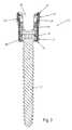
The lower end of the reduction sleeve preferably includes a tapered surface sized and configured to receive a correspondingly tapered surface formed on the bone fixation element.
Preferably, once inserted, the bone anchor extends through the lower end of the reduction sleeve such that the bone anchor may be moveable with respect to the bone fixation element and with respect to the reduction sleeve.
The reduction sleeve may also include an alignment mechanism so that the bone fixation element can only be inserted into the reduction sleeve when the rod-receiving channel formed in the bone fixation element is aligned with the channel formed in the reduction sleeve. The alignment mechanism preferably is sized and configured as an alignment flat formed in the lower end of the reduction sleeve, the alignment flat being sized and configured to contact a corresponding flat formed on the bone fixation element.
The reduction sleeve may also include a protrusion formed on the inner surface thereof, the protrusion projecting inward from the inner surface so that, once inserted, the projection contacts a top surface formed on the bone fixation element. Once inserted, the bone fixation element preferably is secured within the reduction sleeve in-between the lower end of the reduction sleeve and the protrusion.
The bone anchor is preferably sized and configured to engage a patient's vertebra.
The reduction sleeve of claim preferably has the shape of a sleeve or tubular member.
The transverse channel preferably extends from the upper end towards the lower end.
BRIEF DESCRIPTION OF THE DRAWINGS
The system is explained in even greater detail in the following exemplary drawings. The drawings are merely exemplary to illustrate the structure of preferred devices and certain features that may be used singularly or in combination with other features. The invention should not be limited to the embodiments shown.
FIG. 1 is a perspective view of a prior art bone fixation element;
FIG. 2 is a cross-sectional view of the prior art bone fixation element shown inFIG. 1;
FIG. 3 is a perspective view of an exemplary embodiment of a reduction sleeve;
FIG. 4 is a perspective view of a bone fixation element being inserted into the reduction sleeve ofFIG. 3;
FIG. 5 is an alternate exemplary embodiment of a reduction sleeve;
FIG. 6 is a perspective view of the reduction sleeve and bone fixation element ofFIG. 4 being engaged by a screwdriver or other similar type device;
FIG. 7 is a perspective view of the reduction sleeve and bone fixation element ofFIG. 4 with a longitudinal spinal rod shown therein;
FIG. 8A is a perspective view of a reduction instrument urging the spinal rod into the reduction sleeve and bone fixation element;
FIG. 8B is another perspective view of the reduction instrument urging the spinal rod into the reduction sleeve and bone fixation element;
FIG. 9 is a perspective view of another exemplary embodiment of a reduction insertion and screwdriver or other similar type device;
FIG. 10 is a close up, perspective view of the reduction instrument ofFIG. 9 engaging the bone fixation element;
FIG. 11 is another perspective view of the reduction instrument ofFIGS. 8A-10 incorporating a cap alignment tube;
FIG. 12 is a close up, perspective view of the cap alignment tube ofFIG. 11, engaging the bone fixation element;
FIG. 13 is another perspective view of the reduction instrument;
FIG. 14 is a perspective view of another exemplary embodiment of a reduction instrument engaging the set screw or closure cap for urging the spinal rod into the reduction sleeve and bone fixation element;
FIG. 15 is a perspective view of the reduction sleeve and bone fixation element with the spinal rod fully inserted and clamped in the bone fixation element; and
FIG. 16 is a perspective view of the spinal rod fully inserted and clamped in the bone fixation element with the reduction sleeve removed.
DETAILED DESCRIPTION
Certain exemplary embodiments of the invention will now be described with reference to the drawings. In general, such embodiments relate to a reduction sleeve, by way of non-limiting example, a reduction sleeve for use in posterior spinal fixation to facilitate insertion of a longitudinal spinal rod in a rod-receiving channel formed in a bone fixation element. The invention may have other applications and uses and should not be limited to the structure or use described and illustrated. As will be described in greater detail below, the reduction sleeve may include a vertical through-bore sized and configured to receive a bone fixation element and a transverse channel sized and configured to receive a longitudinal spinal rod. The reduction sleeve may also include a break-off point and/or region so that after the longitudinal spinal rod has been inserted in the rod-receiving channel of the bone fixation element, the reduction sleeve can be removed from the patient's body leaving in place the bone fixation element and spinal rod.
While the reduction sleeve will be described as and may generally be used in the spine (for example, in the lumbar, thoracic or cervical regions), those skilled in the art will appreciate that the reduction sleeve may be used for fixation of other parts of the body such as, for example, joints, long bones or bones in the hand, face, feet, extremities, cranium, etc.
As will be described in greater detail below, the reduction sleeve may be used to facilitate insertion of a longitudinal spinal rod into a rod-receiving channel formed in a bone fixation element. It should be understood that the spinal rod may include, but not limited to, a solid rod, a non-solid rod, a flexible or dynamic rod, etc. It should be understood that the reduction sleeve is not limited in use to any particular type of spinal rod.
As will be described in greater detail below, the reduction sleeve may be used in conjunction with a bone fixation element in order to assist the surgeon with insertion of the spinal rod into the rod-receiving channel formed in the bone fixation element. As generally understood by one of ordinary skill in the art, it should be understood that bone fixation element is used generally and may include, but are not limited to, poly-axial or mono-axial pedicle screws, hooks (both mono-axial and poly-axial) including pedicle hooks, transverse process hooks, sublaminar hook, or other fasteners, clamps or implants. One example of a bone fixation element is the Pangea™ pedicle screw system distributed by Synthes® (U.S.A.). As shown inFIGS. 1 and 2, an exemplary embodiment of abone fixation element10 is shown. As shown, thebone fixation element10 may include a bone anchor12 (shown as a bone screw) having anenlarged head portion14, a body portion20 (shown as a top loading body portion) having anupper end22, alower end24, a rod-receiving channel26 (shown as a top loading U-shaped rod-receiving channel) defining a pair of spaced apartarms28,30, asleeve35 and acollet36 slidably disposed within thebody portion20, at least a portion of thecollet36 being slidably disposed within thesleeve35, and a set screw orclosure cap40. In use, theenlarged end portion14 of thebone anchor12 may be separate from and be disposed within thelower end24 of thebody portion20 so that thebone anchor12 can poly-axial rotate with respect to thebody portion20. Alternatively, the bone anchor orhook12 may be formed integral with thebody portion20 to form a monolithic structure which is sometimes referred to as a mono-axial pedicle screw or hook.
Once thespinal rod45 is inserted into the rod-receivingchannel26, the surgeon can secure the position of therod45 with respect to thebody portion20 and the position of thebone anchor12 with respect to thebody portion20 by engaging, for example, by rotating the set screw orclosure cap40. Rotation of the set screw orclosure cap40 may cause the set screw orclosure cap40 to exert a downward force onto thespinal rod45, which is received within the rod-receivingchannel26, which, in turn, causes therod45 to exert a downward force onto thesleeve35 with causes thesleeve35 to move with respect to thecollet36, which in turn causes thecollet36 to compress around theenlarged head portion14 of thebone anchor12 thereby securing the position of thebone anchor12 with respect to thebody portion20. In addition, rotation of the set screw orclosure cap40 may cause thespinal rod45 to be sandwiched in-between the set screw orclosure cap40 and thesleeve35 thereby securing the position of therod45 with respect to thebody portion20.
Thebone fixation element10 may be sized and configured with a low profile so that the height of thebone fixation element10 is minimized in order to reduce the amount of associated trauma. That is, preferably, the overall height of thebody portion20 is minimized so that, once engaged, thebone fixation element10 does not extend anymore than is necessary above the patient's vertebra. The height of the body portion may be between about 10 mm and 25 mm and, preferably, between about 12 mm and 17 mm. It should be understood however that the reduction sleeve is not limited in use to any particular type of bone fixation element.
As shown inFIG. 3, thereduction sleeve100 may be generally in the shape of a sleeve or tubular member having anupper end102, alower end104, aninner surface105, anouter surface106 and alongitudinal axis108. Thereduction sleeve100 may also include a through-bore110 extending from theupper end102 to thelower end104, the through-bore110 being generally orientated parallel to thelongitudinal axis108 for receiving a bone fixation element, such asbone fixation element10, as shown inFIGS. 1 and 2. However, the through-bore can be at an angle with respect to thelongitudinal axis108 of thereduction sleeve100. Thereduction sleeve100 may also include achannel115 that preferably extends from theupper end102 towards thelower end104, thechannel115 being generally orientated transverse to thelongitudinal axis108 for receiving the longitudinal spinal rod, such asspinal rod45, as shown inFIGS. 1 and 2. However, the transverse channel can be at any angle with respect to thelongitudinal axis108 of thereduction sleeve100. Thechannel115 defining a pair of spaced apartarms120,122 which may be joined together in thelower end104 by abridge member124. In this manner, thereduction sleeve100 may be generally in the form of a U-shaped member.
As shown, thereduction sleeve100 may also include a plurality ofthreads150 formed on theouter surface106 of the spaced apartarms120,122 for threadably engaging a reduction instrument, as will be described in greater detail below. Preferably, thethreads150 begin at or near theupper end102 and extend substantially the entire length of the spaced apartarms120,122 and/or the entire length of thechannel115. Alternatively, thereduction sleeve100 may be formed withinternal threads150 formed on theinner surface105 of the spaced apartarms120,122. In addition, it should be understood that other forms of engagement between thereduction sleeve100 and reduction instrument are contemplated, such as, for example, a snap-fit type connection wherein the spaced apartarms120,122 may include a plurality of ridges for engaging a projection formed on the reduction instrument.
As previously described, thebone fixation element10 may be sized and configured with a low profile so that the height of thebone fixation element10, and in particular the height of thebody portion20, is minimized in order to reduce the overall amount of associated trauma. One disadvantage of minimizing the height of thebone fixation element10 is that thespinal rod45 may be vertically and/or horizontally offset with respect to the rod-receivingchannel26 formed in thebone fixation element10 making it more difficult for the surgeon to insert and clamp thespinal rod45 into the rod-receivingchannel26 of thebone fixation element10. To this end, incorporation of thereduction sleeve100 may enable a surgeon to temporary extend the overall height of thebone fixation element10 to facilitate insertion of thespinal rod45 into the rod-receivingchannel26 of thebone fixation element10. Thereafter, once inserted, thereduction sleeve100 may be removed and/or disposed leaving behind thebone fixation element10 and clampedspinal rod45. Thereduction sleeve100 may have a height of about 20 mm to 60 mm and, preferably, between about 28 mm and 35 mm to help facilitate insertion of thespinal rod45 into the rod-receivingchannel26 of thebone fixation element10.
As shown inFIG. 3, thelower end104 of thereduction sleeve100 may include atapered surface160 for receiving thebody portion20 of thebone fixation element10 such that, as best shown inFIG. 4, as thebone fixation element10 is inserted into the through-bore110 of thereduction sleeve100, thebone anchor12 passes through thereduction sleeve100 so that it may engage the patient's vertebra while thebody portion20 of thebone fixation element10 includes asurface21, preferably a corresponding tapered lower surface, sized and configured to be received within thelower end104 of thereduction sleeve100. In this manner, preferably, thebone anchor12 may be poly-axially rotated with respect to thebody portion20 of thebone fixation element10 even after thebone fixation element10 is inserted into thereduction sleeve100. Preferably, thetapered surface160 formed on thelower surface104 of thereduction sleeve100 and the corresponding taperedsurface21 formed on thebone fixation element10 are sized and configured within tight tolerances to help facilitate retention of thebone fixation element10 within thereduction sleeve100. The taperedsurface21 may have a tapered angle of approximately 10 degrees with a height between about 5 mm and about 6 mm.
In use, the rod-receivingchannel26 formed in thebody portion20 of thebone fixation element10 may be sized and configured to align with thechannel115 formed in thereduction sleeve100 so that the longitudinalspinal rod45 may pass completely through thereduction sleeve100 andbone fixation element10 even after thebone fixation element10 has been inserted into thereduction sleeve100. Preferably, thelower end104 of thereduction sleeve100 may include an alignment mechanism so that thebone fixation element10 can only be inserted into thereduction sleeve100 when the rod-receivingchannels26,115 are aligned. For example, as best shown inFIGS. 3 and 4, thelower end104 of thereduction sleeve100 may include an alignment flat175 that may be sized and configured to engage a corresponding flat23 formed on thebody portion20 of thebone fixation element10. As will be generally understood by one of ordinary skill in the art, other alignment mechanism may be used, including, for example, one of thereduction sleeve100 andbone fixation element10 may include a projection for engaging a groove formed on the other of thereduction sleeve100 andbone fixation element10.
As best shown inFIG. 3, thereduction sleeve100 may also include a ledge orprotrusion200 formed and extending inwardly from theinner surface105 of the spaced apartarms120,122. As will be generally appreciated by one of ordinary skill in the art, during insertion of thebone fixation element10 into thereduction sleeve100, the inwardly protruding ledge orprotrusion200 will cause the spaced apartarms28,30 formed on thebody portion20 of thebone fixation element10 to deflect inwards until the top of the spaced apartarms28,30 formed on thebone fixation element10 pass completely beyond that inwardly protruding ledge orprotrusion200. At that point, the spaced apartarms28,30 formed on thebone fixation element10 will revert back to their original, upright position causing thebody portion20 of thebone fixation element10 to be secured within thereduction sleeve100. More particularly, thebody portion20 of thebone fixation element10 will be secured between the inwardly protruding ledge orprotrusion200 and thetapered surface160 formed at thelower end104 of thereduction sleeve100. In this manner, thereduction sleeve100 andbone fixation element10 may be pre-assembled by the manufacturer and/or by the surgeon prior to insertion so that thereduction sleeve100 andbone fixation element10 may be inserted into the patient's vertebra as a single piece. In addition, as previously described, thetapered surface160 formed on thelower surface104 of thereduction sleeve100 and the corresponding taperedsurface21 formed on thebone fixation element10 are sized and configured within tight tolerances to further secure thebone fixation element10 within thereduction sleeve100.
Moreover, as best shown inFIG. 3, thereduction sleeve100 may also include one or more break-off point(s) or region(s)225. Preferably thereduction sleeve100 includes a pair of break off points orregions225 located on thelower end104 of thereduction sleeve100 beneath the rod-receivingchannel115. That is, as shown, preferably the break-off points orregions225 are formed beneath thechannel115 and extend vertically from thechannel115 to thelower end104 of thereduction sleeve100. In this manner, the break-off points orregions225 are located at the smallest and/or weakness point of thereduction sleeve100 making it easier for thereduction sleeve100 to be broken, removed and/or discarded.
The break-off points orregions225 are preferably an area of weakness formed, preferably intentionally, in thereduction sleeve100 so that thereduction sleeve100 will break or rupture when subjected to high stresses, such as by intentional stresses induced by the surgeon in order to break thereduction sleeve100 into multiple pieces so that thereduction sleeve100 can be, partially or completely, removed from the patient's body after the longitudinalspinal rod45 has been seated and secured within the rod-receivingchannel26 of thebone fixation element10. The break-offpoint225 may be configured as a weakened region, a thinned-out area, a groove, etc. As will be appreciated by one of ordinary skill in the art, thereduction sleeve100 may contain any number of break-off points orregions225 located anyway on thereduction sleeve100. Incorporation of the break-off points orregions225 enable thereduction sleeve100 to be discarded. That is, the break-off points orregions225 enable thereduction sleeve100 to be constructed as a separate and distinct part from thebone fixation element10. This, optionally, enables thereduction sleeve100 to be manufactured from a different and/or cheaper material as compared to thebone fixation element10. Moreover, since thereduction sleeve100 is broken and discarded, no sharp edges are left on thebone fixation element10, for example, as compared to prior art bone fixation elements that incorporate integral extension areas via a break-off point or region.
Alternatively, as shown inFIG. 5, thereduction sleeve100 may be configured as a side opening or lateral engagingreduction sleeve100′. In this manner, thereduction sleeve100′ may be sized and configured with a single spaced apartarm120′ for engaging a reduction instrument, as will be described in greater detail below. In this embodiment, the break-offpoint225 may be omitted as thereduction sleeve100′ may be preferably sized and configured to engage thebone fixation element10 from a single side thereof, thus enabling the surgeon to engage and disengage thereduction sleeve100′ as necessary. One particular advantage of this embodiment is that thereduction sleeve100′ is not broken and/or discarded after each use but rather may be reused again during the surgery.
Referring again toFIG. 4, in use, thebone fixation element10 may be inserted into thereduction sleeve100 via the through-bore110 so that preferably thebody portion20 of thebone fixation element10 is seated between thetapered surface160 of thelower end104 of thereduction sleeve100 and the inwardly projecting ledge orprotrusion200 formed on the spaced apartarms120,122. Thebone anchor12 extending through thelower end104 of thereduction sleeve100 and preferably being capable of poly-axially rotating with respect to thebone fixation element10 andreduction sleeve100. Moreover, preferably the rod-receivingchannel26 formed in thebone fixation element10 may be aligned with the rod-receivingchannel115 formed in thereduction sleeve100 so that the longitudinalspinal rod45 is able to pass completely through the assembled device250 (e.g., thereduction sleeve100 with thebone fixation element10 seated therein).
As best shown inFIG. 6, with thebone fixation element10 secured between theinner surface105 of thereduction sleeve100 and the inwardly projecting ledge orprotrusion200, the assembleddevice250 may be secured to a patient's body, preferably the patient's vertebra, by a screwdriver or othersimilar type device300. Once engaged to the patient's vertebra, the surgeon can preferably, so long as a mono-axial bone fixation element isn't used, poly-axially rotate thebody portion20 of thebone fixation element10 and thereduction sleeve100 with respect to thebone anchor12 so that the longiditudinalspinal rod45 can be inserted into the rod-receivingchannel115 of thereduction sleeve100. At this point, thespinal rod45 may or may not be seated within the rod-receivingchannel26 of thebone fixation element10, as best shown inFIG. 7.
Next, as best shown inFIGS. 8A and 8B, areduction instrument310 may be used to engage thereduction sleeve100 in order to urge thespinal rod45 into the rod-receivingchannel26 of thebone fixation element10. Thereduction instrument310 may include atube311 having adistal end312 and aproximal end314, thedistal end312 may include one or more internal threads316 for engaging theexternal threads150 formed on the spaced apartarms120,122 of thereduction sleeve100 such that rotation of thereduction instrument310 causes thereduction instrument310 to move with respect to thereduction sleeve100, which in turn, may cause thedistal end312 of thereduction instrument310 to contact thespinal rod45 so that continued rotation of thereduction instrument310 urges therod45 into the rod-receivingchannel26 of thebone fixation element100. That is, rotation of thereduction instrument310 causes thereduction instrument310 to move with respect to thereduction sleeve100, which, in turn, causes thedistal end312 of thereduction instrument310 to contact thespinal rod45 so that continued rotation of thereduction instrument310 moves therod45 from a first position where therod45 may be in thechannel115 formed in thereduction sleeve100 but not in the rod-receivingchannel26 of thebone fixation element100, as shown inFIG. 8A, to a second position where therod45 may be located in both thechannel115 formed in thereduction sleeve100 and the rod-receivingchannel26 of thebone fixation element100, as shown inFIG. 8B. Alternatively, as previously described, thereduction instrument310 may include external threads for engaging internal threads formed on the spaced apartarms120,122 of thereduction sleeve100 or any other attachment means known in the art. Thereduction sleeve100 andreduction instrument310 are preferably configured with corresponding increased thread pitch to enable faster reduction of thespinal rod45. That is, thereduction sleeve100 andreduction instrument310 may be configured with corresponding increased thread pitch so that less rotation of thereduction instrument310 is required to move thereduction instrument310 axially with respect to thereduction sleeve100. For example, thereduction sleeve100 andreduction instrument310 may be configured with an M15 thread pitch. However, as will be appreciated by one of ordinary skill in the art, any thread pitch may be used. In addition, as shown, thereduction instrument310 may also include ahandle318, preferably a T-handle, to facilitate rotation of thereduction instrument310.
Moreover, as best shown inFIGS. 9 and 10, the reduction instrument310 (shown here with an optionallyknurled knob318′ as opposed to the T-handle318 mentioned above) preferably includes acentral bore320 extending from theproximal end314 to thedistal end312. Thebore320 preferably being sized and configured to receive the set screw orclosure cap40 and associated screwdriver orsimilar type device330 so that once the spinal45 has been urged into the rod-receivingchannel26 formed in thebone fixation element10, the surgeon can clamp thespinal rod45 within the rod-receivingchannel26 of thebone fixation element10 by securing the set screw orclosure cap40 to thebone fixation element10. As will be generally understood by one or ordinary skill in the art, theknurled knob318′ and T-handle318 are easily interchangeable.
In addition, as best shown inFIGS. 11 and 12, thecentral bore320 may be sized and configured to receive an optionalcap alignment tube340. Thecap alignment tube340 may be preferably sized and configured with an alignment mechanism so that when thecap alignment tube340 is inserted into thereduction instrument310, thecap alignment tube340 only permits the set screw orclosure cap40 to be inserted into the spaced apartarms120,122 formed on thebone fixation element10 in proper alignment. More particularly, as shown inFIG. 12, thecap alignment tool340 may include a plurality ofslots345 extending from a distal end344 thereof. Theslots345 being sized and figured to receive and guide tabs41 (as best shown inFIG. 1) extending from the set screw orclosure cap40 into engagement with the spaced apartarms28,30 formed on thebone fixation element10. In addition, thecap alignment tube340 may be preferably sized and configured to prevent thetabs41 formed on the set screw orclosure cap40 from accidentally being dropped into the rod-receivingchannel26 formed on thebone fixation element10. Thecap alignment tool340 may also incorporate a handle (not shown). Preferably thecap alignment tool340 includes a handle extending from theproximal end342 thereof.
As shown inFIG. 13, thereduction instrument310 may also include aviewing window325 formed in a side of thetube311 to enable the surgeon to see the top of thereduction sleeve100 andbone fixation element10. In addition, thereduction instrument310 may also include an indicator327, more preferably an indicator line, to precisely indicate to the surgeon when thespinal rod45 has been fully inserted into the rod-receivingchannel26 formed in thebone fixation element10 to prevent over or under rotation.
Alternatively, as best shown inFIG. 14, thedistal end312 of thereduction instrument310 may be sized and configured to receive and/or engage the set screw orclosure cap40 so that the set screw orclosure cap40 contacts and urges thespinal rod45 into the rod-receivingchannel26 formed on thebone fixation element10. Thus, eliminating the need for the separate set screw ofclosure cap screwdriver330. It should be further noted that as shown in this exemplary embodiment, thereduction sleeve100 has internal threads for engaging external threads formed on thereduction instrument310. Alternatively, however, thereduction sleeve100 could have external threads for engaging internal threads formed on thereduction instrument310.
As best shown inFIG. 15, once thespinal rod45 has been secured within the rod-receivingchannel26 of thebone fixation element10, thereduction instrument310 may be removed. Next thereduction sleeve100 may be removed by breaking thereduction sleeve100 into multiple pieces at the break-offpoint225 leaving the engagedbone fixation element10 and clampedspinal rod45, as shown inFIG. 16.
The reduction sleeve may be manufactured from any biocompatible material known in the art. The reduction sleeve may be manufactured from the same material as the bone fixation element or from a different material. The reduction sleeve may be manufactured from, but not limited to, titanium, titanium alloys, stainless steel, cobalt chromium, fibers, polymers, plastics, etc. Moreover, as will be generally understood by one of ordinary skill in the art, thereduction sleeve100 may be provided in any number of sizes and configurations depending on the size and configuration of the bone fixation elements and spinal rods being used, which may be dependent on the type and location of the surgery being performed.
As will be appreciated by those skilled in the art, any or all of the components described herein such as, for example, the reduction sleeve, spinal rod, bone fixation elements, instruments, etc. may be provided in sets or kits so that the surgeon may select various combinations of components to perform a fixation procedure and create a fixation system which is configured specifically for the particular needs/anatomy of a patient. It should be noted that one or more of each component may be provided in a kit or set. In some kits or sets, the same device may be provided in different shapes and/or sizes (e.g., reduction sleeves of different sizes).
While the foregoing description and drawings represent the preferred embodiments of the present invention, it will be understood that various additions, modifications, combinations and/or substitutions may be made therein without departing from the spirit and scope of the present invention as defined in the accompanying claims. In particular, it will be clear to those skilled in the art that the present invention may be embodied in other specific forms, structures, arrangements, proportions, and with other elements, materials, and components, without departing from the spirit or essential characteristics thereof. One skilled in the art will appreciate that the invention may be used with many modifications of structure, arrangement, proportions, materials, and components and otherwise, used in the practice of the invention, which are particularly adapted to specific environments and operative requirements without departing from the principles of the present invention. In addition, features described herein may be used singularly or in combination with other features. The presently disclosed embodiments are therefore to be considered in all respects as illustrative and not restrictive, the scope of the invention being indicated by the appended claims, and not limited to the foregoing description.

Claims (25)

What is claimed is:
1. A method of facilitating insertion of a spinal rod into a rod-receiving channel formed in a bone fixation element comprising:
providing a reduction sleeve, the reduction sleeve having a longitudinal axis, an upper end having an upper opening, a lower end having a lower opening, an outer surface, a through-bore extending from the upper opening to the lower opening, the through-bore defining an inner surface, and a channel extending from the upper end towards the lower end, the channel being substantially transverse to the longitudinal axis and in communication with the upper end opening, the reduction sleeve further comprising at least one break-off point or region for facilitating breaking the reduction sleeve into multiple pieces,
wherein the through-bore is substantially parallel to the longitudinal axis and is sized and configured for receiving the bone fixation element into the reduction sleeve from the upper end, and
wherein the outer surface of the reduction sleeve includes a plurality of threads for engaging a reduction instrument, the plurality of threads beginning near the upper end and extending substantially an entire length of the channel;
aligning the rod-receiving channel of the bone fixation element with the channel in the reduction sleeve for passing a spinal rod through the channels;
attaching the bone fixation element to bone;
inserting the spinal rod into the channel of the reduction sleeve;
urging the spinal rod into the rod receiving channel of the bone fixation element by engaging the threads on the reduction sleeve and rotating at least a portion of the rod reduction instrument to contact and move the spinal rod down into the channel of the bone fixation element;
securing the spinal rod within the rod-receiving channel of the bone fixation element by threadedly engaging a set screw with the rod receiving channel of the bone fixation element; and
removing the reduction sleeve.
2. The method ofclaim 1, wherein the step of removing the reduction sleeve further comprises the step of breaking the reduction sleeve at the at least one break-off point or region.
3. The method ofclaim 1, wherein the reduction sleeve further comprises an alignment mechanism configured to engage the bone fixation element.
4. The method ofclaim 1, wherein the reduction sleeve further comprises a ledge extending inwardly from the inner surface, and the method further comprises the step of deflecting arms formed on the bone fixation element until the arms pass beyond the ledge.
5. The method ofclaim 1, further comprising the step of inserting the bone fixation element and reduction sleeve into the patient together as an assembly.
6. The method ofclaim 1, wherein the upper end opening is greater than the lower end opening.
7. The method ofclaim 1, further comprising the step of inserting the bone fixation element into the reduction sleeve via the through-bore.
8. The method ofclaim 1, wherein the bone fixation element comprises a body portion and an anchor portion for engaging bone, and the aligning step further comprises polyaxially rotating the body portion of the bone fixation element with respect to the bone anchor portion of the bone fixation element so the spinal rod is insertable into the rod-receiving channel.
9. The method ofclaim 8, further comprising the step of inserting the bone fixation element into the reduction sleeve so that the reduction sleeve substantially surrounds the body portion of the bone fixation element and the bone anchor portion extends beyond the lower opening.
10. The method ofclaim 1, wherein the securing step further comprises inserting the set screw in the through-bore of the reduction instrument.
11. A method of facilitating insertion of a spinal rod into a rod-receiving channel formed in a bone fixation element comprising:
providing a reduction sleeve, the reduction sleeve having a longitudinal axis, an upper end having an upper opening, a lower end having a lower opening, an outer surface, a through-bore extending from the upper opening to the lower opening, the through-bore defining an inner surface, and a channel extending from the upper end towards the lower end, the channel being substantially transverse to the longitudinal axis and in communication with the upper end opening, the reduction sleeve further comprising at least one break-off point or region for facilitating breaking the reduction sleeve into multiple pieces,
wherein the upper end opening is larger than the lower end opening, and the through-bore is substantially parallel to the longitudinal axis and is sized and configured for receiving the bone fixation element into the reduction sleeve from the upper end so that at least a portion of the bone fixation element extends out of the lower end opening, and
wherein the outer surface of the reduction sleeve includes a plurality of threads for engaging a reduction instrument, the plurality of threads beginning near the upper end and extending substantially an entire length of the channel;
inserting the bone fixation element into and through the upper end opening of the reduction sleeve so that at least a portion of the bone fixation element extends out the lower end opening;
aligning the rod-receiving channel of the bone fixation element with the channel in the reduction sleeve for passing a spinal rod through the channels;
attaching the bone fixation element to bone;
urging the spinal rod into the channel of the reduction sleeve and into the rod-receiving channel of the bone fixation element,
securing the spinal rod within the rod-receiving channel of the bone fixation element by threadedly engaging a set screw with the rod receiving channel of the bone fixation element; and
removing the reduction sleeve.
12. The method ofclaim 11, wherein the step of removing the reduction sleeve further comprises the step of breaking the reduction sleeve at the at least one break-off point or region.
13. The method ofclaim 11, wherein the reduction sleeve further comprises an alignment mechanism configured to engage the bone fixation element.
14. The method ofclaim 11, wherein the reduction sleeve further comprises a ledge extending inwardly from the inner surface, further comprising the step of deflecting arms formed on the bone fixation element until the arms pass beyond the ledge.
15. The method ofclaim 11, further comprising inserting the bone fixation element and reduction sleeve into the patient together as an assembly.
16. The method ofclaim 11, wherein the bone fixation element comprises a body portion and an anchor portion for engaging bone, and the aligning step further comprises polyaxially rotating the body portion of the bone fixation element with respect to the bone anchor portion of the bone fixation element so the spinal rod is insertable into the rod-receiving channel.
17. The method ofclaim 11, wherein the bone fixation element comprises a bone anchor portion for engaging bone and a body portion, the method further comprising inserting the bone fixation element so that the reduction sleeve substantially surrounds the body portion of the bone fixation element.
18. The method ofclaim 11, wherein the securing step further comprises inserting the set screw in the through-bore of the reduction instrument.
19. The method ofclaim 11, wherein the urging step further comprises engaging the threads on the reduction sleeve and rotating at least a portion of the rod reduction instrument to contact and move the spinal rod down into the channel of the bone fixation element.
20. A system for facilitating insertion of a spinal rod comprising:
a bone fixation element having a threaded rod-receiving channel formed in a body portion of the bone fixation element and a bone anchor portion for engaging bone, the bone fixation element further comprising a set screw for engaging the threads of the rod receiving channel;
a reduction sleeve having a longitudinal axis, an upper end having an upper opening, a lower end having a lower opening, an outer surface, a through-bore substantially parallel to the longitudinal axis and extending from the upper end opening to the lower end opening, the through-bore defining an inner surface, and a channel extending from the upper end towards the lower end, the channel being substantially transverse to the longitudinal axis, in communication with the upper end opening, and sized and configured for receiving the spinal rod, the reduction sleeve further comprising at least one break-off point or region for facilitating breaking the reduction sleeve into multiple pieces,
wherein the upper end opening is larger than the lower end opening, and the through-bore is sized and configured for receiving and sliding the bone fixation element down into the reduction sleeve from the upper end opening so that the body portion of the bone fixation element is substantially surrounded by the reduction sleeve and in contact with the inner surface of the reduction sleeve but too large to fit through the lower end opening, and the bone anchor portion extends out of the lower end opening, and
wherein the outer surface of the reduction sleeve includes a plurality of threads for engaging a reduction instrument, the plurality of threads beginning near the upper end and extending substantially an entire length of the channel.
21. The system ofclaim 20, wherein the reduction sleeve further comprises an alignment mechanism configured to engage the bone fixation element.
22. The system ofclaim 20, wherein the reduction sleeve further comprises a ledge extending inwardly from the inner surface, the inward ledge configured to deflect arms on the bone fixation element that form the rod receiving channel to permit the bone fixation element to pass beyond the ledge and snap fit the bone fixation element to the reduction sleeve.
23. The system ofclaim 20, wherein the bone fixation element is attachable to the reduction sleeve prior to insertion into the patient.
24. The system ofclaim 20, wherein the reduction instrument is rotatable to move the reduction instrument with respect to the reduction sleeve for contacting the spinal rod.
25. The system ofclaim 20, wherein the reduction instrument is engageable with the set screw of the bone fixation element.
US11/835,1592006-08-222007-08-07Reduction sleeveActive2030-10-21US8663292B2 (en)

Priority Applications (5)

Application NumberPriority DateFiling DateTitle
US11/835,159US8663292B2 (en)2006-08-222007-08-07Reduction sleeve
US14/161,732US9339310B2 (en)2006-08-222014-01-23Reduction sleeve
US15/134,411US9737346B2 (en)2006-08-222016-04-21Reduction sleeve
US15/647,497US10595913B2 (en)2006-08-222017-07-12Reduction sleeve
US16/807,782US12042189B2 (en)2006-08-222020-03-03Reduction sleeve

Applications Claiming Priority (2)

Application NumberPriority DateFiling DateTitle
US83944806P2006-08-222006-08-22
US11/835,159US8663292B2 (en)2006-08-222007-08-07Reduction sleeve

Related Child Applications (1)

Application NumberTitlePriority DateFiling Date
US14/161,732ContinuationUS9339310B2 (en)2006-08-222014-01-23Reduction sleeve

Publications (2)

Publication NumberPublication Date
US20080051794A1 US20080051794A1 (en)2008-02-28
US8663292B2true US8663292B2 (en)2014-03-04

Family

ID=39197638

Family Applications (5)

Application NumberTitlePriority DateFiling Date
US11/835,159Active2030-10-21US8663292B2 (en)2006-08-222007-08-07Reduction sleeve
US14/161,732Active2027-08-16US9339310B2 (en)2006-08-222014-01-23Reduction sleeve
US15/134,411ActiveUS9737346B2 (en)2006-08-222016-04-21Reduction sleeve
US15/647,497ActiveUS10595913B2 (en)2006-08-222017-07-12Reduction sleeve
US16/807,782Active2030-04-04US12042189B2 (en)2006-08-222020-03-03Reduction sleeve

Family Applications After (4)

Application NumberTitlePriority DateFiling Date
US14/161,732Active2027-08-16US9339310B2 (en)2006-08-222014-01-23Reduction sleeve
US15/134,411ActiveUS9737346B2 (en)2006-08-222016-04-21Reduction sleeve
US15/647,497ActiveUS10595913B2 (en)2006-08-222017-07-12Reduction sleeve
US16/807,782Active2030-04-04US12042189B2 (en)2006-08-222020-03-03Reduction sleeve

Country Status (1)

CountryLink
US (5)US8663292B2 (en)

Cited By (15)

* Cited by examiner, † Cited by third party
Publication numberPriority datePublication dateAssigneeTitle
US20110040335A1 (en)*2008-04-222011-02-17Synthes Usa, LlcBone fixation element with reduction tabs
US20150127053A1 (en)*2011-02-182015-05-07SpinewaySurgical device for correcting deformation of the spinal column
US9339310B2 (en)2006-08-222016-05-17DePuy Synthes Products, Inc.Reduction sleeve
US9486256B1 (en)2013-03-152016-11-08Nuvasive, Inc.Rod reduction assemblies and related methods
US9539110B2 (en)2011-01-062017-01-10Darren L. BERGEYInterbody prosthetic device with compound-arc, blade anchor
US9844398B2 (en)2012-05-112017-12-19Orthopediatrics CorporationSurgical connectors and instrumentation
US10136927B1 (en)2013-03-152018-11-27Nuvasive, Inc.Rod reduction assemblies and related methods
US10172647B2 (en)*2009-11-162019-01-08Nexxt Spine, LLCPoly-axial implant fixation system
US10357286B2 (en)2014-03-122019-07-23Safe OrthopaedicsOsteosynthesis system comprising means for straightening a bone anchoring element relative to a screw head and anchoring screw implemented in such a system
US10702317B2 (en)2015-08-132020-07-07K2M, Inc.Extended tab systems for reducing spinal rods
US10973558B2 (en)2017-06-122021-04-13K2M, Inc.Screw insertion instrument and methods of use
US11051861B2 (en)2018-06-132021-07-06Nuvasive, Inc.Rod reduction assemblies and related methods
US11134993B2 (en)2005-09-302021-10-05Roger P. JacksonPivotal bone anchor assembly with snap-in-place insert
US11701238B2 (en)2011-01-062023-07-18Darren L. BERGEYCompressive, orthopedic, anchoring apparatus and method
US12262927B2 (en)2020-12-102025-04-01K2M, Inc.Screw insertion instrument and methods of use

Families Citing this family (58)

* Cited by examiner, † Cited by third party
Publication numberPriority datePublication dateAssigneeTitle
US8366753B2 (en)2003-06-182013-02-05Jackson Roger PPolyaxial bone screw assembly with fixed retaining structure
US7588575B2 (en)*2003-10-212009-09-15Innovative Spinal TechnologiesExtension for use with stabilization systems for internal structures
US7967826B2 (en)*2003-10-212011-06-28Theken Spine, LlcConnector transfer tool for internal structure stabilization systems
US8444681B2 (en)2009-06-152013-05-21Roger P. JacksonPolyaxial bone anchor with pop-on shank, friction fit retainer and winged insert
US9980753B2 (en)2009-06-152018-05-29Roger P Jacksonpivotal anchor with snap-in-place insert having rotation blocking extensions
USD589147S1 (en)*2006-02-022009-03-24Innovative Spinal TechnologiesBone anchor head
WO2007121271A2 (en)2006-04-112007-10-25Synthes (U.S.A)Minimally invasive fixation system
US20080234765A1 (en)*2007-03-132008-09-25Depuy Spine, Inc.Rod reduction methods and devices
US8979904B2 (en)2007-05-012015-03-17Roger P JacksonConnecting member with tensioned cord, low profile rigid sleeve and spacer with torsion control
US8439922B1 (en)2008-02-062013-05-14NiVasive, Inc.Systems and methods for holding and implanting bone anchors
US20090234392A1 (en)*2008-03-132009-09-17Depuy Spine, Inc.Method for inserting a spinal fixation element using implants having guide tabs
US9095386B2 (en)*2008-03-212015-08-04Life Spine, Inc.Spinal rod guide for a vertebral screw spinal rod connector assembly
AU2010260521C1 (en)*2008-08-012013-08-01Roger P. JacksonLongitudinal connecting member with sleeved tensioned cords
FR2937855B1 (en)*2008-11-052010-12-24Warsaw Orthopedic Inc PROGRESSIVE INTRODUCTION INSTRUMENT FOR A VERTEBRAL ROD.
CN102497828B (en)*2009-05-202015-09-09斯恩蒂斯有限公司What patient installed retracts part
US11464549B2 (en)2009-06-152022-10-11Roger P. JacksonPivotal bone anchor assembly with horizontal tool engagement grooves and insert with upright arms having flared outer portions
CN103826560A (en)2009-06-152014-05-28罗杰.P.杰克逊 Polyaxial Bone Anchor with Socket Stem and Winged Inserts with Friction Fit Compression Collars
EP2485654B1 (en)2009-10-052021-05-05Jackson P. RogerPolyaxial bone anchor with non-pivotable retainer and pop-on shank, some with friction fit
US8236032B2 (en)2009-10-202012-08-07Depuy Spine, Inc.Spinal implant with a flexible extension element
WO2011063410A1 (en)*2009-11-232011-05-26Felix QuevedoCam lock pedicle screw
US8828006B2 (en)2010-02-172014-09-09Blackstone Medical, Inc.Anti-splay apparatus
US8535318B2 (en)2010-04-232013-09-17DePuy Synthes Products, LLCMinimally invasive instrument set, devices and related methods
US8206395B2 (en)*2010-06-182012-06-26Spine Wave, Inc.Surgical instrument and method for the distraction or compression of bones
US8512383B2 (en)2010-06-182013-08-20Spine Wave, Inc.Method of percutaneously fixing a connecting rod to a spine
US8603094B2 (en)*2010-07-262013-12-10Spinal Usa, Inc.Minimally invasive surgical tower access devices and related methods
US20120109208A1 (en)*2010-10-272012-05-03Warsaw Orthopedic, Inc.Low Profile Extension Attachments for Bone Anchors
AU2011324058A1 (en)2010-11-022013-06-20Roger P. JacksonPolyaxial bone anchor with pop-on shank and pivotable retainer
US9198698B1 (en)2011-02-102015-12-01Nuvasive, Inc.Minimally invasive spinal fixation system and related methods
US9011449B1 (en)*2011-04-052015-04-21Scott CochranScrew and rod fixation system
US8556904B2 (en)2011-05-052013-10-15Warsaw Orthopedic, Inc.Anchors extender assemblies and methods for using
CN103717159B (en)2011-05-272016-08-17新特斯有限责任公司 Minimally Invasive Spinal Fixation System Including Vertebral Alignment Features
US9204909B2 (en)2011-07-132015-12-08Warsaw Orthopedic, Inc.Spinal rod system and method
US8956361B2 (en)*2011-12-192015-02-17Amendia, Inc.Extended tab bone screw system
CA2846149C (en)2013-03-142018-03-20Stryker SpineSystems and methods for percutaneous spinal fusion
US9980758B2 (en)*2013-11-272018-05-29Blackstone Medical, Inc.Minimally invasive counter-torque wrench system
EP3128933B1 (en)*2014-04-082019-11-13Medacta International SAFixing device for a surgical anchor member
US20150313647A1 (en)*2014-04-302015-11-05Ignacio Sanpera TriguerosSystem for correction of the spine curvatures
US10368923B2 (en)*2014-10-282019-08-06Neurostructures, Inc.Bone fixation system
DE102014117176A1 (en)*2014-11-242016-05-25Aesculap Ag Pedicle screw system and spine stabilization system
US9615855B2 (en)*2015-05-152017-04-11Baui Biotech Co., Ltd.Bone screw and percutaneous minimally invasive pedicle fixation system
US9974577B1 (en)2015-05-212018-05-22Nuvasive, Inc.Methods and instruments for performing leveraged reduction during single position spine surgery
US10398481B2 (en)2016-10-032019-09-03Nuvasive, Inc.Spinal fixation system
US10779866B2 (en)2016-12-292020-09-22K2M, Inc.Rod reducer assembly
WO2018204676A1 (en)2017-05-032018-11-08Advance Research System, LlcExtension ready spinal support systems
US11648037B2 (en)2017-05-032023-05-16Advance Research System, LlcExtension-ready spinal support system with vascular-safe pedicle screw
US10980641B2 (en)2017-05-042021-04-20Neurostructures, Inc.Interbody spacer
US10512547B2 (en)2017-05-042019-12-24Neurostructures, Inc.Interbody spacer
US11076892B2 (en)2018-08-032021-08-03Neurostructures, Inc.Anterior cervical plate
US11071629B2 (en)2018-10-132021-07-27Neurostructures Inc.Interbody spacer
WO2020102787A1 (en)2018-11-162020-05-22Surber, James L.Pivotal bone anchor assembly having a deployable collet insert with internal pressure ring
USD945619S1 (en)*2019-04-042022-03-08Next Orthosurgical, Inc.Straight angled bushing
USD942010S1 (en)*2019-04-042022-01-25Next Orthosurgical, Inc.Curved angled bushing
US11382761B2 (en)2020-04-112022-07-12Neurostructures, Inc.Expandable interbody spacer
US11304817B2 (en)2020-06-052022-04-19Neurostructures, Inc.Expandable interbody spacer
US11717419B2 (en)2020-12-102023-08-08Neurostructures, Inc.Expandable interbody spacer
US11439444B1 (en)*2021-07-222022-09-13Globus Medical, Inc.Screw tower and rod reduction tool
CN117179869A (en)*2022-06-012023-12-08硕果生医科技有限公司Bone screw set
CN115153808B (en)*2022-08-162023-04-07无锡市第九人民医院Traction reductor for fracture of acetabulum

Citations (15)

* Cited by examiner, † Cited by third party
Publication numberPriority datePublication dateAssigneeTitle
US5672176A (en)*1995-03-151997-09-30Biedermann; LutzAnchoring member
US6540748B2 (en)*1999-09-272003-04-01Blackstone Medical, Inc.Surgical screw system and method of use
US6641586B2 (en)*2002-02-012003-11-04Depuy Acromed, Inc.Closure system for spinal fixation instrumentation
US20040162560A1 (en)2003-02-192004-08-19Raynor Donald E.Implant device including threaded locking mechanism
US20040176763A1 (en)*1996-03-222004-09-09Foley Kevin T.Methods for percutaneous surgery
US20040260283A1 (en)*2003-06-192004-12-23Shing-Cheng WuMulti-axis spinal fixation device
US20050065517A1 (en)*2003-09-242005-03-24Chin Kingsley RichardMethods and devices for improving percutaneous access in minimally invasive surgeries
US20060030861A1 (en)*2004-07-212006-02-09Simonson Robert EMethods and devices for retracting tissue in minimally invasive surgery
US20060058794A1 (en)2002-09-062006-03-16Jackson Roger PHelical guide and advancement flange with break-off extensions
US20060083603A1 (en)2000-08-232006-04-20Jackson Roger PReverse angled threadform with anti-splay clearance
US20060111712A1 (en)*2004-11-232006-05-25Jackson Roger PSpinal fixation tool set and method
US20060247630A1 (en)*2005-04-272006-11-02Andrew IottPercutaneous vertebral stabilization system
US20060293693A1 (en)*2005-06-082006-12-28Innovative Spine, LlcSleeve assembly for spinal stabilization system and methods of use
US20070156143A1 (en)*2006-01-032007-07-05Zimmer Spine, Inc.Instrument for pedicle screw adhesive materials
US20070270842A1 (en)*2006-04-112007-11-22Bankoski Brian RMinimally invasive fixation sysyem

Family Cites Families (24)

* Cited by examiner, † Cited by third party
Publication numberPriority datePublication dateAssigneeTitle
US7862587B2 (en)*2004-02-272011-01-04Jackson Roger PDynamic stabilization assemblies, tool set and method
US7621918B2 (en)*2004-11-232009-11-24Jackson Roger PSpinal fixation tool set and method
GB0316539D0 (en)*2003-07-152003-08-20Pfizer LtdCompound testing method
US7001821B2 (en)*2003-11-102006-02-21Texas Instruments IncorporatedMethod of forming and using a hardmask for forming ferroelectric capacitors in a semiconductor device
US7179261B2 (en)*2003-12-162007-02-20Depuy Spine, Inc.Percutaneous access devices and bone anchor assemblies
US7842044B2 (en)*2003-12-172010-11-30Depuy Spine, Inc.Instruments and methods for bone anchor engagement and spinal rod reduction
ATE441376T1 (en)*2003-12-172009-09-15Depuy Spine Inc INSTRUMENTS AND PROCEDURES FOR BONE ANCHOR PROCEDURES AND SPINAL BAR REDUCTION
US7476240B2 (en)*2004-02-062009-01-13Depuy Spine, Inc.Devices and methods for inserting a spinal fixation element
US7651502B2 (en)*2004-09-242010-01-26Jackson Roger PSpinal fixation tool set and method for rod reduction and fastener insertion
US7666189B2 (en)*2004-09-292010-02-23Synthes Usa, LlcLess invasive surgical system and methods
US20060089651A1 (en)*2004-10-262006-04-27Trudeau Jeffrey LApparatus and method for anchoring a surgical rod
US8075591B2 (en)*2004-11-092011-12-13Depuy Spine, Inc.Minimally invasive spinal fixation guide systems and methods
WO2006057837A1 (en)*2004-11-232006-06-01Jackson Roger PSpinal fixation tool attachment structure
US8177817B2 (en)*2005-05-182012-05-15Stryker SpineSystem and method for orthopedic implant configuration
ES2326123T3 (en)*2005-05-272009-10-01Biedermann Motech Gmbh RECEPTION PART TO CONNECT A VARTAGE OF AN OSEO ANCHORAGE ELEMENT WITH A BEAR ANCHORAGE BAR AND DEVICE WITH SUCH A RECEPTION PART.
US7846093B2 (en)*2005-09-262010-12-07K2M, Inc.Minimally invasive retractor and methods of use
US7520879B2 (en)*2006-02-072009-04-21Warsaw Orthopedic, Inc.Surgical instruments and techniques for percutaneous placement of spinal stabilization elements
US8663292B2 (en)2006-08-222014-03-04DePuy Synthes Products, LLCReduction sleeve
US8052720B2 (en)*2006-11-092011-11-08Zimmer Spine, Inc.Minimally invasive pedicle screw access system and associated method
US8262662B2 (en)*2006-11-202012-09-11Depuy Spine, Inc.Break-off screw extensions
US8007519B2 (en)*2007-03-132011-08-30Zimmer Spine, Inc.Dynamic spinal stabilization system and method of using the same
US7922725B2 (en)*2007-04-192011-04-12Zimmer Spine, Inc.Method and associated instrumentation for installation of spinal dynamic stabilization system
US8251901B2 (en)*2007-10-082012-08-28Greatbatch Medical S.A.Retractor for minimally invasive surgery
US8142436B2 (en)*2008-06-062012-03-27X-Spine Systems, Inc.Retraction tube for use with bone screw

Patent Citations (15)

* Cited by examiner, † Cited by third party
Publication numberPriority datePublication dateAssigneeTitle
US5672176A (en)*1995-03-151997-09-30Biedermann; LutzAnchoring member
US20040176763A1 (en)*1996-03-222004-09-09Foley Kevin T.Methods for percutaneous surgery
US6540748B2 (en)*1999-09-272003-04-01Blackstone Medical, Inc.Surgical screw system and method of use
US20060083603A1 (en)2000-08-232006-04-20Jackson Roger PReverse angled threadform with anti-splay clearance
US6641586B2 (en)*2002-02-012003-11-04Depuy Acromed, Inc.Closure system for spinal fixation instrumentation
US20060058794A1 (en)2002-09-062006-03-16Jackson Roger PHelical guide and advancement flange with break-off extensions
US20040162560A1 (en)2003-02-192004-08-19Raynor Donald E.Implant device including threaded locking mechanism
US20040260283A1 (en)*2003-06-192004-12-23Shing-Cheng WuMulti-axis spinal fixation device
US20050065517A1 (en)*2003-09-242005-03-24Chin Kingsley RichardMethods and devices for improving percutaneous access in minimally invasive surgeries
US20060030861A1 (en)*2004-07-212006-02-09Simonson Robert EMethods and devices for retracting tissue in minimally invasive surgery
US20060111712A1 (en)*2004-11-232006-05-25Jackson Roger PSpinal fixation tool set and method
US20060247630A1 (en)*2005-04-272006-11-02Andrew IottPercutaneous vertebral stabilization system
US20060293693A1 (en)*2005-06-082006-12-28Innovative Spine, LlcSleeve assembly for spinal stabilization system and methods of use
US20070156143A1 (en)*2006-01-032007-07-05Zimmer Spine, Inc.Instrument for pedicle screw adhesive materials
US20070270842A1 (en)*2006-04-112007-11-22Bankoski Brian RMinimally invasive fixation sysyem

Cited By (29)

* Cited by examiner, † Cited by third party
Publication numberPriority datePublication dateAssigneeTitle
US11849977B2 (en)2005-09-302023-12-26Roger P. JacksonPivotal bone anchor assembly with receiver having horizontal and vertical tool engagement grooves
US11134993B2 (en)2005-09-302021-10-05Roger P. JacksonPivotal bone anchor assembly with snap-in-place insert
US9737346B2 (en)2006-08-222017-08-22DePuy Synthes Products, Inc.Reduction sleeve
US9339310B2 (en)2006-08-222016-05-17DePuy Synthes Products, Inc.Reduction sleeve
US12042189B2 (en)2006-08-222024-07-23DePuy Synthes Products, Inc.Reduction sleeve
US10595913B2 (en)2006-08-222020-03-24DePuy Synthes Products, Inc.Reduction sleeve
US20110040335A1 (en)*2008-04-222011-02-17Synthes Usa, LlcBone fixation element with reduction tabs
US10172647B2 (en)*2009-11-162019-01-08Nexxt Spine, LLCPoly-axial implant fixation system
US9539110B2 (en)2011-01-062017-01-10Darren L. BERGEYInterbody prosthetic device with compound-arc, blade anchor
US10898345B2 (en)2011-01-062021-01-26Darren L. BERGEYCompound-arc, splined anchor
US11826264B2 (en)2011-01-062023-11-28Darren L. BERGEYCompound-arc, splined anchor
US10195051B2 (en)2011-01-062019-02-05Darren L. BERGEYCompound-arc, splined anchor
US11701238B2 (en)2011-01-062023-07-18Darren L. BERGEYCompressive, orthopedic, anchoring apparatus and method
US9259245B2 (en)*2011-02-182016-02-16SpinewaySurgical device for correcting deformation of the spinal column
US20150127053A1 (en)*2011-02-182015-05-07SpinewaySurgical device for correcting deformation of the spinal column
US10729472B2 (en)2012-05-112020-08-04Orthopediatrics CorporationSurgical connectors and instrumentation
US9844398B2 (en)2012-05-112017-12-19Orthopediatrics CorporationSurgical connectors and instrumentation
US10898241B2 (en)2013-03-152021-01-26Nuvasive, Inc.Rod reduction assemblies and related methods
US9486256B1 (en)2013-03-152016-11-08Nuvasive, Inc.Rod reduction assemblies and related methods
US10136927B1 (en)2013-03-152018-11-27Nuvasive, Inc.Rod reduction assemblies and related methods
US11660128B2 (en)2013-03-152023-05-30Nuvasive, Inc.Rod reduction assemblies and related methods
US10357286B2 (en)2014-03-122019-07-23Safe OrthopaedicsOsteosynthesis system comprising means for straightening a bone anchoring element relative to a screw head and anchoring screw implemented in such a system
US10702317B2 (en)2015-08-132020-07-07K2M, Inc.Extended tab systems for reducing spinal rods
US11839415B2 (en)2015-08-132023-12-12K2M, Inc.Extended tab systems for reducing spinal rods
US11678914B2 (en)2017-06-122023-06-20K2M, Inc.Screw insertion instrument and methods of use
US10973558B2 (en)2017-06-122021-04-13K2M, Inc.Screw insertion instrument and methods of use
US11051861B2 (en)2018-06-132021-07-06Nuvasive, Inc.Rod reduction assemblies and related methods
US12369954B2 (en)2018-06-132025-07-29Nuvasive, Inc.Rod reduction assemblies and related methods
US12262927B2 (en)2020-12-102025-04-01K2M, Inc.Screw insertion instrument and methods of use

Also Published As

Publication numberPublication date
US10595913B2 (en)2020-03-24
US12042189B2 (en)2024-07-23
US20160228161A1 (en)2016-08-11
US9737346B2 (en)2017-08-22
US9339310B2 (en)2016-05-17
US20140135854A1 (en)2014-05-15
US20200197053A1 (en)2020-06-25
US20080051794A1 (en)2008-02-28
US20170303976A1 (en)2017-10-26

Similar Documents

PublicationPublication DateTitle
US12042189B2 (en)Reduction sleeve
US10856910B2 (en)System and method for insertion of flexible spinal stabilization element
EP2265202B1 (en)Bone fixation element with reduction tabs
US7491207B2 (en)Rod persuader
AU2008316641B2 (en)Surgical fixation system and related methods
EP2768411B1 (en)Derotation apparatus for treating spinal irregularities
US8992536B2 (en)Coplanar deformity correction system
US9480505B2 (en)Bi-planar persuader
US10368914B2 (en)Fusion systems and methods of assembly and use

Legal Events

DateCodeTitleDescription
ASAssignment

Owner name:SYNTHES (U.S.A.), PENNSYLVANIA

Free format text:ASSIGNMENT OF ASSIGNORS INTEREST;ASSIGNORS:DEC, BRIAN;RATHBUN, DAVID S.;REEL/FRAME:022522/0213

Effective date:20070801

ASAssignment

Owner name:SYNTHES USA, LLC, PENNSYLVANIA

Free format text:CHANGE OF NAME;ASSIGNOR:SYNTHES (U.S.A.);REEL/FRAME:022826/0140

Effective date:20081223

Owner name:SYNTHES USA, LLC,PENNSYLVANIA

Free format text:CHANGE OF NAME;ASSIGNOR:SYNTHES (U.S.A.);REEL/FRAME:022826/0140

Effective date:20081223

ASAssignment

Owner name:HAND INNOVATIONS LLC, FLORIDA

Free format text:ASSIGNMENT OF ASSIGNORS INTEREST;ASSIGNOR:DEPUY SPINE, LLC;REEL/FRAME:030359/0001

Effective date:20121230

Owner name:DEPUY SPINE, LLC, MASSACHUSETTS

Free format text:ASSIGNMENT OF ASSIGNORS INTEREST;ASSIGNOR:SYNTHES USA, LLC;REEL/FRAME:030358/0945

Effective date:20121230

Owner name:DEPUY SYNTHES PRODUCTS, LLC, MASSACHUSETTS

Free format text:CHANGE OF NAME;ASSIGNOR:HAND INNOVATIONS LLC;REEL/FRAME:030359/0036

Effective date:20121231

FEPPFee payment procedure

Free format text:PAYOR NUMBER ASSIGNED (ORIGINAL EVENT CODE: ASPN); ENTITY STATUS OF PATENT OWNER: LARGE ENTITY

STCFInformation on status: patent grant

Free format text:PATENTED CASE

ASAssignment

Owner name:DEPUY SYNTHES PRODUCTS, INC., MASSACHUSETTS

Free format text:CHANGE OF NAME;ASSIGNOR:DEPUY SYNTHES PRODUCTS, LLC;REEL/FRAME:037595/0177

Effective date:20141219

ASAssignment

Owner name:HAND INNOVATIONS LLC, FLORIDA

Free format text:CORRECTIVE ASSIGNMENT TO CORRECT THE INCORRECT APPL. NO. 13/486,591 PREVIOUSLY RECORDED AT REEL: 030359 FRAME: 0001. ASSIGNOR(S) HEREBY CONFIRMS THE ASSIGNMENT;ASSIGNOR:DEPUY SPINE, LLC;REEL/FRAME:042621/0565

Effective date:20121230

ASAssignment

Owner name:DEPUY SPINE, LLC, MASSACHUSETTS

Free format text:CORRECTIVE ASSIGNMENT TO CORRECT THE INCORRECT APPLICATION NO. US 13/486,591 PREVIOUSLY RECORDED ON REEL 030358 FRAME 0945. ASSIGNOR(S) HEREBY CONFIRMS THE ASSIGNMENT;ASSIGNOR:SYNTHES USA, LLC;REEL/FRAME:042687/0849

Effective date:20121230

MAFPMaintenance fee payment

Free format text:PAYMENT OF MAINTENANCE FEE, 4TH YEAR, LARGE ENTITY (ORIGINAL EVENT CODE: M1551)

Year of fee payment:4

MAFPMaintenance fee payment

Free format text:PAYMENT OF MAINTENANCE FEE, 8TH YEAR, LARGE ENTITY (ORIGINAL EVENT CODE: M1552); ENTITY STATUS OF PATENT OWNER: LARGE ENTITY

Year of fee payment:8

MAFPMaintenance fee payment

Free format text:PAYMENT OF MAINTENANCE FEE, 12TH YEAR, LARGE ENTITY (ORIGINAL EVENT CODE: M1553); ENTITY STATUS OF PATENT OWNER: LARGE ENTITY

Year of fee payment:12


[8]ページ先頭

©2009-2025 Movatter.jp