US8663223B2 - Surgical treatment apparatus - Google Patents
Surgical treatment apparatusDownload PDFInfo
- Publication number
- US8663223B2 US8663223B2US13/281,875US201113281875AUS8663223B2US 8663223 B2US8663223 B2US 8663223B2US 201113281875 AUS201113281875 AUS 201113281875AUS 8663223 B2US8663223 B2US 8663223B2
- Authority
- US
- United States
- Prior art keywords
- section
- treatment
- electrode
- output
- treatment section
- Prior art date
- Legal status (The legal status is an assumption and is not a legal conclusion. Google has not performed a legal analysis and makes no representation as to the accuracy of the status listed.)
- Active, expires
Links
Images


Classifications
- A—HUMAN NECESSITIES
- A61—MEDICAL OR VETERINARY SCIENCE; HYGIENE
- A61B—DIAGNOSIS; SURGERY; IDENTIFICATION
- A61B17/00—Surgical instruments, devices or methods
- A61B17/32—Surgical cutting instruments
- A61B17/320068—Surgical cutting instruments using mechanical vibrations, e.g. ultrasonic
- A61B17/320092—Surgical cutting instruments using mechanical vibrations, e.g. ultrasonic with additional movable means for clamping or cutting tissue, e.g. with a pivoting jaw
- A—HUMAN NECESSITIES
- A61—MEDICAL OR VETERINARY SCIENCE; HYGIENE
- A61B—DIAGNOSIS; SURGERY; IDENTIFICATION
- A61B18/00—Surgical instruments, devices or methods for transferring non-mechanical forms of energy to or from the body
- A61B18/04—Surgical instruments, devices or methods for transferring non-mechanical forms of energy to or from the body by heating
- A61B18/12—Surgical instruments, devices or methods for transferring non-mechanical forms of energy to or from the body by heating by passing a current through the tissue to be heated, e.g. high-frequency current
- A61B18/14—Probes or electrodes therefor
- A61B18/1442—Probes having pivoting end effectors, e.g. forceps
- A61B18/1445—Probes having pivoting end effectors, e.g. forceps at the distal end of a shaft, e.g. forceps or scissors at the end of a rigid rod
- A—HUMAN NECESSITIES
- A61—MEDICAL OR VETERINARY SCIENCE; HYGIENE
- A61B—DIAGNOSIS; SURGERY; IDENTIFICATION
- A61B17/00—Surgical instruments, devices or methods
- A61B17/28—Surgical forceps
- A61B17/2812—Surgical forceps with a single pivotal connection
- A61B17/282—Jaws
- A61B2017/2825—Inserts of different material in jaws
- A—HUMAN NECESSITIES
- A61—MEDICAL OR VETERINARY SCIENCE; HYGIENE
- A61B—DIAGNOSIS; SURGERY; IDENTIFICATION
- A61B17/00—Surgical instruments, devices or methods
- A61B17/32—Surgical cutting instruments
- A61B17/320068—Surgical cutting instruments using mechanical vibrations, e.g. ultrasonic
- A61B17/320092—Surgical cutting instruments using mechanical vibrations, e.g. ultrasonic with additional movable means for clamping or cutting tissue, e.g. with a pivoting jaw
- A61B2017/320093—Surgical cutting instruments using mechanical vibrations, e.g. ultrasonic with additional movable means for clamping or cutting tissue, e.g. with a pivoting jaw additional movable means performing cutting operation
- A—HUMAN NECESSITIES
- A61—MEDICAL OR VETERINARY SCIENCE; HYGIENE
- A61B—DIAGNOSIS; SURGERY; IDENTIFICATION
- A61B17/00—Surgical instruments, devices or methods
- A61B17/32—Surgical cutting instruments
- A61B17/320068—Surgical cutting instruments using mechanical vibrations, e.g. ultrasonic
- A61B17/320092—Surgical cutting instruments using mechanical vibrations, e.g. ultrasonic with additional movable means for clamping or cutting tissue, e.g. with a pivoting jaw
- A61B2017/320095—Surgical cutting instruments using mechanical vibrations, e.g. ultrasonic with additional movable means for clamping or cutting tissue, e.g. with a pivoting jaw with sealing or cauterizing means
- A—HUMAN NECESSITIES
- A61—MEDICAL OR VETERINARY SCIENCE; HYGIENE
- A61B—DIAGNOSIS; SURGERY; IDENTIFICATION
- A61B18/00—Surgical instruments, devices or methods for transferring non-mechanical forms of energy to or from the body
- A61B2018/00994—Surgical instruments, devices or methods for transferring non-mechanical forms of energy to or from the body combining two or more different kinds of non-mechanical energy or combining one or more non-mechanical energies with ultrasound
Definitions
- the present inventionrelates to a surgical treatment apparatus which uses both ultrasonic vibration and high-frequency current to carry out a surgical treatment on living tissue.
- Jpn. Pat. Appln. KOKAI Publication No. 2008-11987has disclosed a surgical treatment instrument which uses both ultrasonic vibration and high-frequency current to treat living tissue. That is, in this surgical treatment instrument, a proximal end portion of a probe is coupled to an ultrasonic vibrator. The probe is inserted through an insertion sheath, and a distal end portion of the probe protrudes from a distal end portion of the insertion sheath to form a treatment section.
- a grip memberthat can be opened or closed relative to the treatment section is provided at the distal end portion of the insertion sheath. The grip member is closed relative to the treatment section so that the living tissue can be gripped by the treatment section and the grip member.
- ultrasonic vibration generated by the ultrasonic vibratoris transmitted by the probe to ultrasonically vibrate the treatment section.
- a high-frequency voltageis applied between the treatment section and the grip member to pass a high-frequency current through the living tissue.
- the surgical treatment using ultrasonic vibrationprovides a satisfactory cutting function
- the surgical treatment using high-frequency currentprovides a satisfactory coagulation function.
- the use of these surgical treatmentstogether realizes surgical coagulation/cutting treatments that provide satisfactory cutting and coagulation functions.
- a surgical treatment apparatusconfigured to be held and operated by a surgeon, the surgical treatment apparatus includes a vibration generator configured to generate ultrasonic vibration; a vibration transmission section configured to axially transmit the ultrasonic vibration generated in the vibration generator from a proximal end portion to a distal end portion; a treatment section which is formed at the distal end portion of the vibration transmission section, and which is configured to ultrasonically vibrate in an ultrasonic treatment and configured to function as a first electrode in a high-frequency treatment; a grip member which is provided to be openable or closable relative to the treatment section, and which is configured to be closed relative to the treatment section to grip living tissue; an electrode section which is provided in the grip member, and which is configured to function as a second electrode in the high-frequency treatment; a receptacle which is provided in the grip member, and which is configured to abut onto the treatment section so that a predetermined clearance is formed between the electrode section and the treatment section when the grip member is closed relative to the treatment section;
- FIG. 1is a perspective view showing a surgical treatment system according to a first embodiment of the present invention
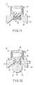
- FIG. 2is a partial longitudinal sectional side view showing a distal grip section according to the first embodiment of the present invention in a closed state;
- FIG. 3is a partial longitudinal sectional side view showing the distal grip section according to the first embodiment of the present invention in an open state;
- FIG. 4is a partial longitudinal sectional side view showing a grip member according to the first embodiment of the present invention.
- FIG. 5is a cross-sectional view showing the distal grip section according to the first embodiment of the present invention in a normal state
- FIG. 6is a cross-sectional view showing the distal grip section according to the first embodiment of the present invention in a worn state
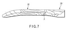
- FIG. 7is a view showing a stress distribution of a treatment section according to the first embodiment of the present invention.
- FIG. 8is a block diagram showing the surgical treatment system according to the first embodiment of the present invention.
- FIG. 9is a cross-sectional view showing the distal grip section according to a second embodiment of the present invention.
- FIG. 10is a cross-sectional view showing the distal grip section according to one referential embodiment of a first referential invention
- FIG. 11is a cross-sectional view showing the grip member according to a modification of the referential embodiment of the first referential invention
- FIG. 12is a cross-sectional view showing the distal grip section according to one referential embodiment of a second referential invention in a normal state
- FIG. 13is a cross-sectional view showing the distal grip section according to the referential embodiment of the second referential invention in a worn and joined state;
- FIG. 14is a cross-sectional view showing the grip member according to a modification of the referential embodiment of the second referential invention.
- FIG. 15is a longitudinal sectional view showing a detection rubber lining according to one referential embodiment of a third referential invention in a normal state
- FIG. 16is a longitudinal sectional view showing the detection rubber lining according to the referential embodiment of the third referential invention in a worn and short-circuited state;
- FIG. 17is a longitudinal sectional view showing the detection rubber lining according to a modification of the referential embodiment of the third referential invention in a normal state;
- FIG. 18is a longitudinal sectional view showing the detection rubber lining according to a modification of the referential embodiment of the third referential invention in a worn and short-circuited state;
- FIG. 19is a schematic circuit diagram showing the surgical treatment system according to one referential embodiment of a fourth referential invention in a normal state.
- FIG. 20is a schematic circuit diagram showing the surgical treatment system according to the referential embodiment of the fourth referential invention in a short-circuited state.
- the first embodiment of the present inventionis described with reference to FIG. 1 to FIG. 7 .
- a surgical treatment systemis described with reference to FIG. 1 .
- the surgical treatment systemuses both ultrasonic vibration and high-frequency current to carry out surgical coagulation/cutting treatments on living tissue, and uses high-frequency current to carry out a surgical coagulation treatment on living tissue.
- the surgical treatment systemincludes a surgical treatment instrument 21 as a surgical treatment apparatus configured to be held and operated by a surgeon.
- the surgical treatment instrument 21is connected to an output device 22 via a composite cable 23 as a connector.
- a sheath unit 24 , a handle unit 26 , and a vibrator unit 27are detachably connected from the distal side to the proximal side in order.
- the vibrator unit 27includes therein an ultrasonic vibrator 28 as a vibration generator.
- the ultrasonic vibrator 28is configured to convert a drive signal input from the output device 22 to a mechanical vibration, and configured to generate ultrasonic vibration.
- a proximal end portion of a probe 29 as a vibration transmission sectionis coupled to the ultrasonic vibrator 28 .
- the probe 29is configured to axially transmit the ultrasonic vibration from the proximal end portion to a distal end portion.
- the probe 29is inserted through the handle unit 26 and the sheath unit 24 .
- the probe 29is inserted through an insertion sheath 31 .
- the distal end portion of the probe 29protrudes from a distal opening of the insertion sheath 31 , thus forming treatment section 32 .
- a grip member 33is provided at a distal end portion of the insertion sheath 31 .
- the grip member 33can open or close relative to the treatment section 32 in an opening/closing directions perpendicular to an axial directions of the probe.
- a distal grip section 34is formed by the treatment section 32 and the grip member 33 .
- the handle unit 26is provided with a fixed handle 36 and a movable handle 37 .
- the fixed handle 36is provided with a switch section 38 .
- a cutting switch 39 a and a coagulation switch 39 bare provided in the switch section 38 .
- first and second electrical paths 99 f and 99 s used in a high-frequency treatmentare formed from the output device 22 to the grip member 33 and the treatment section 32 of the surgical treatment instrument 21 via the composite cable 23 , respectively.
- a drive signalis output to the ultrasonic vibrator 28 from the output device 22 .
- the ultrasonic vibrator 28 to which the drive signal is inputgenerates ultrasonic vibration.
- the generated ultrasonic vibrationis transmitted by the probe 29 , and the treatment section 32 at the distal end portion of the probe 29 is ultrasonically vibrated.
- a high-frequency voltageis applied between the grip member 33 and the treatment section 32 via the first and second electrical paths 99 f and 99 s by the output device 22 .
- the distal grip section 34 of the surgical treatment instrument 21is described in detail with reference to FIG. 2 to FIG. 7 .
- the insertion sheath 31is formed by an outer sheath 41 o and an inner sheath 41 i .
- the outer sheath 41 othe outside of a conductive metal pipe is covered with an insulating resin tube.
- the inner sheath 41 iis a conductive metal pipe. The inner sheath 41 i can be axially moved back and forth relative to the outer sheath 41 o.
- the probe 29is made of a conductive material having high acoustic effects and biocompatibility, for example, a titanium alloy such as a Ti-6Al-4V alloy.
- an insulating and elastic rubber lining 42is externally equipped in the position of each node of the ultrasonic vibration.
- the rubber lining 42is disposed between the inner sheath 41 i and the probe 29 in a compressed state.
- the probe 29is held to the inner sheath 41 i by the rubber lining 42 .
- a clearanceis maintained between the inner sheath 41 i and the probe 29 .
- An abutting portion 43is formed by the part of the treatment section 32 facing the grip member 33 at the distal end portion of the probe 29 .
- the treatment section 32is octagonal in its cross section perpendicular to the axial directions of the probe 29 .
- An abutting surface 44is formed by one surface of the abutting portion 43 facing the grip member 33 .
- a pair of electrode surfaces 46are formed by surfaces provided to both sides of the abutting surface 44 .
- the grip member 33is formed by a body member 47 , an electrode member 48 , a pad member 49 , and a regulating member 51 as a regulating section.
- the body member 47is made of a hard and conductive material. A proximal end portion of the body member 47 constitutes a pivot connection portion 52 .
- the pivot connection portion 52is pivotally connected to a distal end portion of the outer sheath 41 o via a pivot connection shaft 55 .
- the pivot connection shaft 55extends in width directions perpendicular to both the axial directions and the opening/closing directions.
- the body member 47can turn about the pivot connection shaft 55 in the opening/closing directions relative to the outer sheath 41 o .
- a distal end portion of the inner sheath 41 iis pivotally connected to the pivot connection portion 52 of the body member 47 at a position provided to the distal side and the opening-direction side of the pivot connection shaft 55 .
- a distal part of the body member 47constitutes a pair of pivot bearings 53 .
- the pair of pivot bearings 53are in the form of plates which extend in the axial directions and which are perpendicular to the width directions, and are disposed apart from each other in the width directions.
- the electrode member 48is made of a hard and conductive material.
- the part of the electrode member 48 provided on the opening-direction sideconstitutes a pivot support 54 .
- An insertion hole 56is formed through the pivot support 54 in the width directions.
- a pivot support shaft 57is inserted through the insertion hole 56 and extends in the width directions.
- the pivot support 54is disposed between the pair of pivot bearings 53 of the body member 47 , and is pivotally supported on the pair of pivot bearings 53 via the pivot support shaft 57 .
- the electrode member 48can oscillate about the pivot support shaft 57 relative to the body member 47 .
- the part of the electrode member 48 provided on the closing-direction sideconstitutes an electrode section 58 .
- the electrode section 58extends in the axial directions, and projects to both sides in the width directions.
- a recessed groove 59which is open toward the closing direction extends in the axial directions in the part of the electrode section 58 provided on the closing-direction side. Teeth are axially provided in both parts of the groove 59 provided in the closing direction side, thus forming a tooth portion 61 .
- Both side surfaces that define the groove 59constitute a pair of electrode receiving surfaces 62 that are inclined from the closing direction toward both sides in the width directions.
- a recessed mating receptacle 63which is open toward the closing direction axially extends in a bottom portion that defines the groove 59 .
- An embedding hole 64is formed through the pivot support 54 of the electrode member 48 in the opening/closing directions perpendicularly to the insertion hole 56 . The embedding hole 64 is open to the mating receptacle 63 .
- the pad member 49is softer than the probe 29 , and is made of an insulating material having biocompatibility such as polytetrafluorethylene.
- the pad member 49is mated with the mating receptacle 63 of the electrode member 48 .
- the part of the pad member 49 provided on the closing-direction sideprotrudes from the electrode member 48 to the closing direction, thus forming an abutting receptacle 66 .
- the abutting receptacle 66is in a recessed shape corresponding to the projecting shape of the abutting portion 43 of the treatment section 32 .
- the abutting portion 43 of the treatment section 32abuts onto and engages with the abutting receptacle 66 of the pad member 49 .
- the pair of electrode surfaces 46 of the treatment section 32are arranged parallel to the pair of electrode receiving surfaces 62 of the electrode section 58 , and a clearance is maintained between the electrode section 58 and the treatment section 32 .
- the regulating member 51is harder than the probe 29 , and is made of an insulating high-strength material such as ceramics.
- the regulating member 51is pin-shaped.
- the regulating member 51is inserted into the embedding hole 64 of the pivot support 54 of the electrode member 48 , protrudes toward the mating receptacle 63 of the electrode section 58 , and is embedded in the abutting receptacle 66 of the pad member 49 in the mating receptacle 63 .
- a closing-direction end of the regulating member 51constitutes a regulating end 67 .
- the regulating end 67does not protrude from the abutting receptacle 66 to the closing direction, and is accommodated in the abutting receptacle 66 .
- the insertion hole 56is also formed through the regulating member 51 , and the pivot support shaft 57 is inserted through the insertion hole 56 of the regulating member 51 .
- the inner sheath 41 i , the body member 47 , and the electrode member 48are electrically connected to one another, and constitute the first electrical path 99 f used in a high-frequency surgical treatment.
- the electrode section 58 of the electrode member 48functions as one of bipolar electrodes used in a high-frequency surgical treatment.
- the probe 29constitutes the second electrical path 99 s used in the high-frequency treatment.
- the treatment section 32 provided to the distal end portion of the probe 29functions as the other of the bipolar electrodes used in a high-frequency treatment. As described above, the probe 29 is held to the inner sheath 41 i by the insulating rubber lining 42 , and the clearance is maintained between the inner sheath 41 i and the probe 29 .
- the pad member 49is softer than the probe 29 . Therefore, the abutting receptacle 66 is worn by the treatment section 32 in the case where the treatment section 32 is ultrasonically vibrated when the grip member 33 is closed relative to the treatment section 32 and the abutting portion 43 of the treatment section 32 abuts onto and engages with the abutting receptacle 66 of the pad member 49 . As the abutting receptacle 66 is worn, the clearance between the electrode section 58 and the treatment section 32 is gradually reduced when the abutting portion 43 is in a frictional engagement with the abutting receptacle 66 .
- the regulating end 67 of the regulating member 51is exposed from the abutting receptacle 66 in the closing direction.
- the regulating end 67contacts the treatment section 32 before the electrode section 58 contacts the treatment section 32 if the grip member 33 is closed relative to the treatment section 32 .
- the contact between the treatment section 32 and the electrode section 58is regulated.
- the electrode section 58 and the treatment section 32are hard.
- the treatment section 32when the ultrasonically vibrated treatment section 32 contacts the electrode section 58 , the treatment section 32 rapidly and repetitively comes in and out of contact with the electrode section 58 .
- sparkingoccurs between the treatment section 32 and the electrode section 58 .
- the contact between the treatment section 32 and the electrode section 58is regulated by the regulating end 67 of the regulating member 51 , so that sparking is prevented.
- the regulating member 51is made of an insulating material, and is electrically insulated relative to the electrode member 48 .
- the regulating member 51is made of a high-strength material harder than the probe 29 . Therefore, when the regulating end 67 contacts the ultrasonically vibrated treatment section 32 , the regulating member 51 is not worn, and the probe 29 cracks.
- the regulating end 67contacts the treatment section 32 to intentionally crack the probe 29 . By detecting this crack, the end of the life of the surgical treatment instrument 21 is detected. Therefore, the position of the contact between the treatment section 32 and the regulating end 67 is set at the stress concentration region in the treatment section 32 to ensure that the probe 29 cracks when the regulating end 67 contacts the treatment section 32 .
- a stress concentration regionis located at the proximal end portion of the treatment section 32 .
- a stress concentration region Pis located at the curved root of the treatment section 32 in the curved probe 29 that is moderately curved in a J-shape toward the distal end.
- the surgical treatment systemwhen normally used, carries out coagulation/cutting treatments and a coagulation treatment on living tissue.
- the treatment systemwhen used to carry out coagulation/cutting treatments, living tissue is gripped by the distal grip section 34 , and the cutting switch 39 a of the handle unit 26 is depressed.
- the depression of the cutting switch 39 ais detected by a switch detection section 68 , and a cutting operation signal is output from the switch detection section 68 to a control section 69 .
- the control section 69 to which the cutting operation signal is inputis configured to control an ultrasonic waveform output section 71 and a high-frequency output section 72 .
- the ultrasonic waveform output section 71is configured to output a drive signal to the ultrasonic vibrator 28 , and ultrasonic vibration is generated in the ultrasonic vibrator 28 .
- the ultrasonic vibration generated in the ultrasonic vibrator 28is transmitted by the probe 29 , and the treatment section 32 provided at the distal end portion of the probe 29 is ultrasonically vibrated in contact with the gripped living tissue.
- the high-frequency output section 72configured to apply a high-frequency voltage between the electrode section 58 and the treatment section 32 via the first and second electrical paths 99 f and 99 s , and a high-frequency current is passed through the gripped living tissue.
- both ultrasonic vibration and high-frequency currentare used to carry out, on the living tissue gripped by the distal grip section 34 , coagulation/cutting treatments that provide satisfactory cutting and coagulation functions.
- the coagulation switch 39 b of the handle unit 26is depressed.
- a coagulation operation signalis output from the switch detection section 68 to the control section 69 .
- the high-frequency output section 72is controlled by the control section 69 so that a high-frequency current is passed through the living tissue gripped by the distal grip section 34 .
- the high-frequency currentis used to carry out, on the living tissue gripped by the distal grip section 34 , a coagulation treatment that provides a satisfactory coagulation function.
- Phase-locked loop control(hereinafter referred to as PLL control) is used by the control section 69 as a method of controlling the ultrasonic waveform output section 71 .
- control section 69is configured to scan the frequency of the drive signal output from the ultrasonic waveform output section 71 within a predetermined range around a previously detected resonant frequency.
- An output current and an output voltage of the drive signalare detected by a drive signal detection section 73 .
- the drive signal detection section 73is configured to output the detected output current and output voltage to an impedance detection section 74 and a resonant frequency detection section 76 .
- the impedance detection section 74is configured to detect impedance from the input output current and output voltage, and configured to output the current and voltage to the resonant frequency detection section 76 .
- the resonant frequency detection section 76is configured to detect a frequency from the input output current and output voltage, and further configured to detect, as a resonant frequency, a frequency at which the input impedance is minimized, and then output the resonant frequency to the control section 69 .
- the control section 69is configured to scan the frequency of the drive signal within a predetermined range around the newly input resonant frequency.
- the surgical treatment systemwhen normally used, is always configured to perform a crack detection to detect cracks caused in the probe 29 .
- the probe 29may crack, for example, if the probe 29 is excessively loaded when ultrasonic waveforms are output.
- the impedance detected by the above-mentioned PLL controlis also output to an impedance abnormality determination section 78 from the impedance detection section 74 .
- the impedance abnormality determination section 78is configured to determine that the probe 29 has cracked if a variation of the impedance per unit time has exceeded an experimentally predetermined threshold.
- a crack detection section used in detecting cracks in the probe 29is formed by the drive signal detection section 73 , the impedance detection section 74 , the resonant frequency detection section 76 , and the impedance abnormality determination section 78 .
- the control section 69is configured to activate an alarm 79 to report the crack to the surgeon, and configured to forcibly stop the output of the drive signal by the ultrasonic waveform output section 71 and also forcibly stop the output of the high-frequency current by the high-frequency output section 72 .
- the surgical treatment systemwhen normally used, is always configured to perform short-circuit detection to detect a short circuit between the treatment section 32 and the electrode section 58 .
- a short circuitmay be caused between the treatment section 32 and the electrode section 58 if the treatment section 32 and the electrode section 58 contact the same conductive member when ultrasonic waveforms are output.
- a high-frequency current detection section 80is configured to detect the output current of the high-frequency current output from the high-frequency output section 72 , and configured to output this current to a current abnormality determination section 81 .
- the current abnormality determination section 81is configured to determine that a short circuit has occurred between the treatment section 32 and the electrode section 58 .
- a short-circuit detection sectionconfigured to detect whether a short circuit has occurred between the treatment section 32 and the electrode section 58 is formed by the high-frequency current detection section 80 and the current abnormality determination section 81 .
- the control section 69is configured to activate the alarm 79 to report the short circuit to the surgeon, and configured to forcibly stop the output of the high-frequency current by the high-frequency output section 72 , and also forcibly stop, if any, the output of the drive signal by the ultrasonic waveform output section 71 .
- a warning that reports the crack or short circuitmay be displayed on a monitor that shows an endoscopic observation image.
- the surgical treatment systemis configured to perform a life detection to detect the end of the life of the surgical treatment instrument 21 .
- the regulating end 67 of the regulating member 51contacts the treatment section 32 to intentionally crack the probe 29 , and this crack is detected to detect the end of the life of the surgical treatment instrument 21 .
- the treatment section 32is ultrasonically vibrated while the abutting portion 43 of the treatment section 32 abuts onto and engages with the abutting receptacle 66 of the pad member 49 . Therefore, after the completion of the cutting, the abutting receptacle 66 is worn by the treatment section 32 . As the surgical treatment instrument 21 is repeatedly used, the abutting receptacle 66 is gradually worn, and the surgical treatment instrument 21 comes to the end of its life.
- the surgical treatment systemis configured to perform the crack detection when carrying out coagulation/cutting treatments. Therefore, even when the probe 29 has cracked as a result of contact between the regulating end 67 and the treatment section 32 , the alarm 79 is activated to report the crack to the surgeon, and the output of the drive signal by the ultrasonic waveform output section 71 and the output of the high-frequency current by the high-frequency output section 72 are forcibly stopped. The use of the surgical treatment instrument 21 is then stopped, and the surgical treatment instrument 21 is properly disposed of. Otherwise, the sheath unit 24 and the probe 29 alone may be disposed of, and the use of the handle unit 26 and the vibrator unit 27 may be continued.
- the surgical treatment system according to the present embodimenthas the following advantageous effects.
- the regulating end 67 of the regulating member 51contacts the treatment section 32 before the electrode section 58 of the grip member 33 contacts the treatment section 32 , thereby regulating the contact of the electrode section 58 with the treatment section 32 .
- the regulating member 51has insulating properties, no sparking occurs between the treatment section 32 and the regulating end 67 even if the regulating end 67 contacts the treatment section 32 . This prevents sparking between the treatment section 32 and the grip member 33 .
- the abutting receptacle 66 of the pad member 49is worn more than a predetermined amount, so that the regulating end 67 of the regulating member 51 contacts the treatment section 32 .
- the probe 29cracks.
- the crackis then reported by the alarm 79 , and the output of the drive signal by the ultrasonic waveform output section 71 and the output of the high-frequency current by the high-frequency output section 72 are stopped.
- the regulating end 67is designed to contact the stress concentration region of the treatment section 32 . This ensures that the probe 29 rapidly and certainly cracks when the regulating end 67 contacts the treatment section 32 .
- the regulating member 51is made of an insulating material in the embodiment described above, the regulating member 51 may be made of a conductive material when the regulating member 51 is insulated from the electrode member 48 , for example, by an additional insulating member. Moreover, the regulating end 67 of the regulating member 51 is embedded in the abutting receptacle 66 of the pad member 49 .
- the regulating member 51may be disposed in the grip member 33 in any manner as long as the regulating member 51 contacts the treatment section 32 before the electrode section 58 contacts the treatment section 32 so that the contact of the electrode section 58 with the treatment section 32 can be regulated, when the grip member 33 is closed relative to the treatment section 32 after the abutting receptacle 66 of the pad member 49 is worn more than a predetermined amount.
- the second embodiment of the present inventionis described with reference to FIG. 9 .
- a pair of electrode receiving surfaces 62are formed in the electrode section 58 of the grip member 33 , and a pair of electrode surfaces 46 are formed in the abutting portion 43 of the treatment section 32 , as in the first embodiment.
- the pair of electrode receiving surfaces 62make a predetermined angle ⁇ with the pair of electrode surfaces 46 and form an expanding shape that expands toward the closing direction in a state that the pair of electrode receiving surfaces 62 depart from the pair of electrode surfaces 46 in the width directions.
- a first referential invention of the present inventionis described below.
- the surgical treatment system according to the present referential embodimentresembles the surgical treatment system according to the first embodiment in configuration. The difference therebetween is mainly described below.
- a deformable member 82 as a deformable sectionis used instead of the regulating member 51 .
- the deformable member 82is similar in shape and location to the regulating member 51 .
- the deformable member 82is made of a conductive and elastic material such as conductive rubber, and is electrically connected to the electrode member 48 .
- a closing-direction end of the deformable member 82constitutes a deformable end 85 .
- the deformable end 85 of the deformable member 82contacts the treatment section 32 before the electrode section 58 of the electrode member 48 contacts the treatment section 32 when the grip member 33 is closed relative to the treatment section 32 provided at the distal end portion of the probe 29 .
- the deformable member 82is made of an elastic material.
- the deformable end 85is deformed in accordance with the ultrasonic vibration of the treatment section 32 and thus kept in contact with the treatment section 32 , and the deformable end 85 does not rapidly come in and out of contact with the treatment section 32 .
- the deformable member 82is made of a conductive material and is electrically connected to the electrode section 58 , sparking between the treatment section 32 and the deformable end 85 is avoided, and sparking between the treatment section 32 and the grip member 33 is prevented, even when a high-frequency voltage is applied between the treatment section 32 and the electrode section 58 .
- the surgical treatment systemis configured to detect the end of the life of the surgical treatment instrument 21 by detecting a short circuit. That is, the abutting receptacle 66 of the pad member 49 is worn, and the surgical treatment instrument 21 comes to the end of its life. If the abutting receptacle 66 is further worn, the deformable end 85 of the deformable member 82 is exposed from the abutting receptacle 66 , and the deformable end 85 contacts the treatment section 32 , so that a short circuit occurs between the treatment section 32 and the electrode section 58 via the deformable member 82 .
- the surgical treatment systemis configured to perform short-circuit detection when carrying out coagulation/cutting treatments.
- the alarm 79is activated to report the short circuit to the surgeon, and the output of the drive signal by the ultrasonic waveform output section 71 and the output of the high-frequency current by the high-frequency output section 72 are forcibly stopped.
- the surgical treatment system according to the present embodimenthas the following advantageous effects.
- the deformable end 85 of the deformable member 82contacts the treatment section 32 before the electrode section 58 of the grip member 33 contacts the treatment section 32 .
- the deformable member 82is conductive and is electrically connected to the electrode section 58 , but is elastic.
- the deformable end 85is deformed in accordance with the ultrasonic vibration of the treatment section 32 , and kept in contact with the treatment section 32 . This avoids sparking between the treatment section 32 and the deformable end 85 , and prevents sparking between the treatment section 32 and the grip member 33 .
- the abutting receptacle 66 of the pad member 49is worn more than a predetermined amount, so that the deformable end 85 of the deformable member 82 contacts the treatment section 32 , and a short circuit occurs between the treatment section 32 and the electrode section 58 via the deformable member 82 .
- the short circuitis reported, and the output of the drive signal by the ultrasonic waveform output section 71 and the output of the high-frequency current by the high-frequency output section 72 are stopped. This permits the end of the life of the surgical treatment instrument 21 to be easily recognized, and prevents output from being continued while a short circuit is occurring between the treatment section 32 and the electrode section 58 .
- the deformable member 82is made of a conductive leaf spring member, or a conductive foil member such as an aluminum foil.
- the deformable member 82 according to the present modificationis deformed in accordance with the ultrasonic vibration of the treatment section 32 , and kept in contact with the treatment section 32 to prevent sparking.
- a short circuitoccurs between the treatment section 32 and the electrode section 58 .
- the surgical treatment system according to the present referential embodimentresembles the surgical treatment system according to the first embodiment in configuration. The difference therebetween is mainly described below.
- a fusible member 83 as a fusible sectionis used instead of the regulating member 51 .
- the fusible member 83has a pin shape similar to that of the regulating member 51 , and is disposed in the same manner as the regulating member 51 .
- the fusible member 83is conductive, and is electrically connected to the electrode member 48 of the grip member 33 .
- a closing-direction end of the fusible member 83constitutes a fusible end 84 .
- the fusible member 83is made of a material of the same quality as the probe 29 such that the fusible end 84 and the treatment section 32 are welded together by a short-circuit current when a short circuit occurs between the electrode section 58 and the treatment section 32 provided at the distal end portion of the probe 29 via the fusible member 83 .
- the fusible member 83is also made of the Ti-6Al-4V alloy.
- the fusible end 84 of the fusible member 83contacts the treatment section 32 before the electrode section 58 contacts the treatment section 32 when the grip member 33 is closed relative to the treatment section 32 provided at the distal end portion of the probe 29 .
- a high-frequency voltageis applied between the treatment section 32 and the electrode section 58 , a short circuit occurs between the treatment section 32 and the electrode member 48 via the fusible member 83 .
- the fusible member 83is made of a material of the same quality as the probe 29 .
- the fusible end 84is welded to the treatment section 32 by a short-circuit current and is kept in contact with the treatment section 32 , and does not rapidly and repetitively come in and out of contact with the treatment section 32 . This avoids sparking between the treatment section 32 and the fusible end 84 , and prevents sparking between the treatment section 32 and the grip member 33 .
- the fusible end 84is welded to the treatment section 32 , so that the end of the life of the surgical treatment instrument 21 can be recognized, and the surgical treatment instrument 21 cannot be reused.
- the surgical treatment systemis configured to perform short-circuit detection when carrying out coagulation/cutting treatments. Thus, even when a short circuit occurs between the electrode section 58 and the treatment section 32 via the fusible member 83 by the contact between the fusible end 84 and the treatment section 32 , the alarm 79 is activated to report the short circuit to the surgeon, and the output of the drive signal by the ultrasonic waveform output section 71 and the output of the high-frequency current by the high-frequency output section 72 are forcibly stopped.
- the surgical treatment system according to the present referential embodimenthas the following advantageous effects.
- the fusible end 84 of the fusible member 83contacts the treatment section 32 before the electrode section 58 contacts the treatment section 32 .
- a short circuitoccurs between the treatment section 32 and the electrode section 58 via the fusible member 83 , the fusible end 84 is welded to the treatment section 32 by the short-circuit current, and the contact between the treatment section 32 and the fusible end 84 is maintained.
- the fusible end 84is welded to the treatment section 32 . This permits the end of the life of the surgical treatment instrument 21 to be easily recognized, and ensures that the improper reuse of the surgical treatment instrument 21 is prevented.
- the abutting receptacle 66 of the pad member 49is worn more than a predetermined amount, so that the fusible end 84 of the fusible member 83 contacts the treatment section 32 , and a short circuit occurs between the treatment section 32 and the electrode section 58 .
- the output of the drive signal by the ultrasonic waveform output section 71 and the output of the high-frequency current by the high-frequency output section 72are stopped. This prevents output from being continued while a short circuit is occurring between the treatment section 32 and the electrode section 58 .
- the distal grip section 34prevents sparking by welding the fusible end 84 to the treatment section 32 .
- sparkingmay occur between the treatment section 32 and the fusible end 84 only for a short time at the moment when the treatment section 32 and the fusible end 84 contact each other.
- the grip member 33 according to the present modificationuses a pair of walls 86 configured to a spreading of the sparks. That is, the pair of walls 86 extend to the closing direction from both closing-direction ends of the electrode member 48 , are disposed substantially perpendicularly to the width directions, and extend in the axial directions. Even if sparking occurs between the treatment section 32 and the fusible end 84 , the spreading of the sparks is prevented by the pair of walls 86 .
- a third referential invention of the present inventionis described below.
- the surgical treatment system according to the present referential embodimentresembles the surgical treatment system according to the first embodiment in configuration. The difference therebetween is mainly described below.
- the inner sheath 41 ias an inner peripheral surface and an inner member is moved back and forth relative to the outer sheath 41 o as an outer member in the insertion sheath 31 as a cylindrical member, as with the surgical treatment instrument 21 according to the first embodiment.
- the inner sheath 41 iopens or closes the grip member 33 relative to the treatment section 32 of the probe 29 , and constitutes the first electrical path 99 f used in a high-frequency treatment.
- the probe 29constitutes the second electrical path 99 s used in a high-frequency treatment.
- the probe 29is held to the inner sheath 41 i by the rubber linings 42 .
- a most distal side detection rubber lining 42 dhas its diametrically inner part formed by a conductive section 87 and its diametrically outer part formed by an insulating section 88 .
- the conductive section 87is made of a conductive and elastic material such as conductive rubber, externally equipped to the probe 29 , and electrically connected to the probe 29 .
- the insulating section 88is made of an insulating and elastic material such as insulating rubber, covered with the diametrically outer surface of the conductive section 87 , disposed between the conductive section 87 and the inner sheath 41 i , and insulates the conductive section 87 and the inner sheath 41 i from each other.
- the insulating section 88is worn as a result of mechanical friction between the insulating section 88 and the inner surface of the inner sheath 41 i caused by the back-and-forth motion of the inner sheath 41 i and as a result of melting attributed to heat caused by the friction.
- the conductive section 87is exposed by the wear of the insulating section 88 , and the conductive section 87 contacts the inner sheath 41 i , before the electrode section 58 of the grip member 33 contacts the treatment section 32 provided at the distal end portion of the probe 29 .
- the movable handle 37When living tissue is treated by the surgical treatment system, the movable handle 37 is turned relative to the fixed handle 36 in the handle unit 26 , so that the inner sheath 41 i is moved back and forth relative to the outer sheath 41 o , and the grip member 33 is opened/closed relative to the treatment section 32 . As a result of the back-and-forth motion of the inner sheath 41 i , the insulating section 88 is worn by the friction between the inner surface of the inner sheath 41 i and the insulating section 88 .
- the conductive section 87is exposed by the wear of the insulating section 88 , and the conductive section 87 contacts the inner sheath 41 i , before the electrode section 58 of the grip member 33 contacts the treatment section 32 .
- the surgical treatment systemis configured to perform short-circuit detection when the high-frequency waveforms are output.
- the alarm 79is activated to report the short circuit to the surgeon, and the output of the drive signal by the ultrasonic waveform output section 71 and the output of the high-frequency current by the high-frequency output section 72 are forcibly stopped.
- the end of the life of the surgical treatment instrument 21is detected by the short-circuit detection, and the use of the surgical treatment instrument 21 is ended before the abutting receptacle 66 of the pad member 49 is worn and the electrode section 58 of the grip member 33 contacts the treatment section 32 to cause sparking. This avoids sparking between the treatment section 32 and the electrode section 58 , and prevents sparking between the treatment section 32 and the grip member 33 .
- the surgical treatment system according to the present referential embodimenthas the following advantageous effects.
- the insulating section 88 of the detection rubber lining 42 dis worn by the friction between the inner sheath 41 i and the insulating section 88 . Accordingly, the conductive section 87 of the detection rubber lining 42 d contacts the inner sheath 41 i , and a short circuit occurs between the first electrical path 99 f of the inner sheath 41 i and the second electrical path 99 s of the probe 29 via the conductive section 87 .
- the end of the life of the surgical treatment instrument 21is detected by the short-circuit detection, and the use of the surgical treatment instrument 21 is stopped. This avoids sparking between the treatment section 32 and the electrode section 58 , and prevents sparking between the treatment section 32 and the grip member 33 . Moreover, the output of the drive signal by the ultrasonic waveform output section 71 and the output of the high-frequency current by the high-frequency output section 72 are stopped by the short-circuit detection. This permits the end of the life of the surgical treatment instrument 21 to be easily recognized, and prevents output from being continued while a short circuit is occurring between the first electrical path 99 f and the second electrical path 99 s.
- the most distal side detection rubber lining 42 dis disposed in a position different from the position of the node of the ultrasonic vibration in the probe 29 .
- the detection rubber lining 42 dis ultrasonically vibrated in the axial directions together with the probe 29 , and is worn as a result of mechanical friction between the detection rubber lining 42 d and the inner surface of the inner sheath 41 i attributed to the ultrasonic vibration and as a result of melting attributed to heat caused by the friction.
- the surgical treatment system according to the present referential embodimentresembles the surgical treatment system according to the first embodiment in configuration. The difference therebetween is mainly described below.
- the first electrical path 99 f used in a high-frequency treatmentis formed from the high-frequency output section 72 of the output device 22 to the electrode section 58 of the grip member 33 of the surgical treatment instrument 21
- the second electrical path 99 s used in a high-frequency treatmentis formed from the high-frequency output section 72 of the output device 22 to the treatment section 32 of the probe 29 of the surgical treatment instrument 21 , as in the surgical treatment system according to the first embodiment.
- a noninductive resistance 89 of 10 to 1000 ⁇lies in the first electrical path 99 f .
- the noninductive resistance 89may lie in the second electrical path 99 s rather than in the first electrical path 99 f .
- No regulating member 51is provided in the grip member 33 .
- living tissue 91is gripped by the electrode section 58 of the grip member 33 and the treatment section 32 of the probe 29 .
- the first electrical path 99 f and the second electrical path 99 sare electrically connected to each other by the gripped living tissue 91 so that a closed circuit is formed and a high-frequency current is passed through this closed circuit.
- the living tissue 91functions as an electrical resistance.
- the noninductive resistanceis less than or equal to 1000 ⁇ , a necessary degree of high-frequency current is passed through the living tissue 91 , and a sufficient coagulation function is ensured.
- the electrode section 58 of the grip member 33when the electrode section 58 of the grip member 33 is closed relative to the treatment section 32 provided at the distal end portion of the probe 29 after the abutting receptacle 66 of the pad member 49 is worn more than a predetermined amount, the electrode section 58 contacts the treatment section 32 , and the treatment section 32 rapidly and repetitively comes in and out of contact with the electrode section 58 simultaneously with the application of a high-frequency voltage between the electrode section 58 and the treatment section 32 .
- the noninductive resistance 89 greater than or equal to 10 ⁇lies in the first electrical path 99 f , the passage of an excessive current through the closed circuit is avoided. This avoids sparking between the treatment section 32 and the electrode section 58 , and prevents sparking between the treatment section 32 and the grip member 33 .
- the resistance value of the noninductive resistance 89is preferably adjusted in each surgical treatment instrument 21 , and the noninductive resistance 89 is preferably provided in the surgical treatment instrument 21 rather than in the output device 22 . Even when the noninductive resistance 89 is provided in the surgical treatment instrument 21 , heat generation is avoided in the noninductive resistance 89 , which prevents the surgeon from feeling discomfort from the heat generation. Moreover, the surgical treatment instrument 21 does not need to be provided with any additional cooling mechanism, which prevents the surgical treatment instrument 21 from increasing in size and decreasing in operability.
- noninductive resistance 89it is also possible to use a normal electrical resistance that generates heat. In this case, it is preferable to dispose the electrical resistance in the output device 22 , and use an existing cooling mechanism of the output device 22 to cool the electrical resistance.
- a surgical treatment apparatusconfigured to be held and operated by a surgeon includes a vibration generator configured to generate ultrasonic vibration; a vibration transmission section configured to axially transmit the ultrasonic vibration generated in the vibration generator from a proximal end portion to a distal end portion, the vibration transmission section including a treatment section which is formed at the distal end portion of the vibration transmission section and which is configured to ultrasonically vibrate in an ultrasonic treatment and configured to function as a first electrode in a high-frequency treatment; and a grip member which is openable or closable relative to the treatment section and which is configured to be closed relative to the treatment section to grip living tissue between the grip member and the treatment section, the grip member including a receptacle configured to contact the treatment section and to be worn by the ultrasonic vibration of the treatment section when the grip member is closed relative to the treatment section, an electrode section which is insulated from the receptacle and which is located apart from the treatment section when the treatment section contacts the
- the deformable sectioncontacts the treatment section before the electrode section contacts the treatment section when the grip member is closed relative to the treatment section after the receptacle is worn more than a predetermined amount.
- the deformable sectionis conductive and is electrically connected to the electrode section.
- the deformable sectionis deformed in accordance with the ultrasonic vibration of the treatment section, and kept in contact with the treatment section. This avoids sparking between the treatment section and the deformable section, and prevents sparking between the treatment section and the grip member.
- a surgical treatment systemincludes the surgical treatment apparatus; an output device configured to perform an output to the surgical treatment apparatus; and a connector which electrically connects the surgical treatment apparatus and the output device to each other, wherein the output device includes an ultrasonic waveform output section configured to output, to the vibration generator, a drive signal to drive the vibration generator, a high-frequency output section configured to output a high-frequency current used in the high-frequency treatment to the treatment section and the electrode section, a short-circuit detection section configured to detect whether a short circuit has occurred between the treatment section and the electrode section, and a control section configured to control the ultrasonic waveform output section and the high-frequency output section, the control section being configured to stop the output of the drive signal to the vibration generator by the ultrasonic waveform output section and also to stop the output of the high-frequency current to the treatment section and the electrode section by the high-frequency output section when the short-circuit detection section detects a short circuit.
- the output deviceincludes an ultrasonic waveform output section configured to output, to the vibration generator,
- the output of the drive signal by the ultrasonic waveform output section and the output of the high-frequency current by the high-frequency output sectionare stopped. This permits the end of the life of the surgical treatment apparatus to be easily recognized, and prevents output from being continued while a short circuit is occurring between the treatment section and the electrode section.
- a surgical treatment apparatusconfigured to be held and operated by a surgeon includes a vibration generator configured to generate ultrasonic vibration; a vibration transmission section configured to axially transmit the ultrasonic vibration generated in the vibration generator from a proximal end portion to a distal end portion, the vibration transmission section including a treatment section which is formed at the distal end portion of the vibration transmission section and which is configured to ultrasonically vibrate in an ultrasonic treatment and configured to function as a first electrode in a high-frequency treatment; and a grip member which is openable or closable relative to the treatment section and which is configured to be closed relative to the treatment section to grip living tissue between the grip member and the treatment section, the grip member including a receptacle configured to contact the treatment section and to be worn by the ultrasonic vibration of the treatment section when the grip member is closed relative to the treatment section, an electrode section which is insulated from the receptacle and which is located apart from the treatment section when the treatment section contacts the
- the fusible sectioncontacts the treatment section before the electrode section contacts the treatment section when the grip member is closed relative to the treatment section after the receptacle is worn more than a predetermined amount.
- a short circuitoccurs between the treatment section and the electrode section via the fusible section
- the fusible sectionis welded to the treatment section by the short-circuit current, and contact between the treatment section and the fusible section is maintained.
- the fusible sectionis welded to the treatment section. This permits the end of the life of the surgical treatment apparatus to be easily recognized, and ensures that the improper reuse of the surgical treatment apparatus is prevented.
- a surgical treatment systemincludes the surgical treatment apparatus; an output device configured to perform an output to the surgical apparatus; and a connector which electrically connects the surgical treatment apparatus and the output device to each other, wherein the output device includes an ultrasonic waveform output section configured to output, to the vibration generator, a drive signal to drive the vibration generator, a high-frequency output section configured to output a high-frequency current used in the high-frequency treatment to the treatment section and the electrode section, a short-circuit detection section configured to detect whether a short circuit has occurred between the treatment section and the electrode section, and a control section configured to control the ultrasonic waveform output section and the high-frequency output section, the control section being configured to stop the output of the drive signal to the vibration generator by the ultrasonic waveform output section and also to stop the output of the high-frequency current to the treatment section and the electrode section by the high-frequency output section when the short-circuit detection section detects a short circuit.
- the output deviceincludes an ultrasonic waveform output section configured to output, to the vibration generator, a
- the receptaclewhen the receptacle is worn more than a predetermined amount so that the fusible section contacts the treatment section and a short circuit occurs between the treatment section and the electrode section, the output of the drive signal by the ultrasonic waveform output section and the output of the high-frequency current by the high-frequency output section are stopped. This prevents output from being continued while a short circuit is occurring between the treatment section and the electrode section.
- a surgical treatment systemincludes a surgical apparatus configured to be held and operated by a surgeon; an output device configured to perform an output to the surgical treatment apparatus; and a connector which electrically connects the surgical treatment apparatus and the output device to each other, wherein the surgical treatment apparatus includes a vibration generator configured to generate ultrasonic vibration, a vibration transmission section configured to axially transmit the ultrasonic vibration generated in the vibration generator from a proximal end portion to a distal end portion and configured to function as a first electrical path in a high-frequency treatment, the vibration transmission section including a treatment section which is formed at the distal end portion of the vibration transmission section and which is configured to ultrasonically vibrate in an ultrasonic treatment and which functions as a first electrode in the high-frequency treatment, a cylindrical member through which the vibration transmission section is inserted, the cylindrical member including an inner peripheral surface configured to function as a second electrical path in the high-frequency treatment, a holding member which is provided in the vibration transmission section and which is elastic
- the insulating sectionis worn by the friction between the insulating section and the inner peripheral surface of the cylindrical member.
- the conductive sectioncontact the inner peripheral surface, and a short circuit occurs between the vibration transmission section serving as the first electrical path and the inner peripheral surface serving as the second electrical path via the conductive section. Therefore, the end of the life of the surgical treatment apparatus is detected by the detection of the short circuit, and the use of the surgical treatment apparatus is ended. This avoids sparking between the treatment section and the electrode section, and prevents sparking between the treatment section and the grip member.
- the output of the drive signal by the ultrasonic waveform output section and the output of the high-frequency current by the high-frequency output sectionare stopped by the detection of the short circuit. This permits the end of the life of the surgical treatment apparatus to be easily recognized, and prevents output from being continued while a short circuit is occurring between the first electrical path and the second electrical path.
- a surgical treatment systemincludes a surgical treatment apparatus configured to be held and operated by a surgeon; an output device configured to perform an output to the surgical treatment apparatus; and a connector which electrically connects the surgical treatment apparatus and the output device to each other, wherein the surgical treatment apparatus includes a vibration generator configured to generate ultrasonic vibration, a vibration transmission section configured to axially transmit the ultrasonic vibration generated in the vibration generator from a proximal end portion to a distal end portion, the vibration transmission section including a treatment section which is formed at the distal end portion of the vibration transmission section and which is configured to ultrasonically vibrate in an ultrasonic treatment and configured to function as a first electrode in a high-frequency treatment, and a grip member which is openable or closable relative to the treatment section and which is configured to be closed relative to the treatment section to grip living tissue between the grip member and the treatment section, the grip member including a receptacle configured to contact the treatment section and to be worn by the ultra
- the electrical resistance of 10 to 1000 ⁇is provided in one electrical path in the high-frequency treatment.
- the electrical resistanceis less than or equal to 1000 ⁇ . Therefore, when living tissue is gripped by the treatment section and the electrode section and thus has the high-frequency treatment carried out on it, a necessary degree of high-frequency current in the treatment is passed through the gripped living tissue, and a sufficient coagulation function can be ensured.
- the electrical resistanceis greater than or equal to 10 ⁇ . This avoids sparking between the treatment section and the electrode section, and prevents sparking between the treatment section and the grip member, even when the receptacle is worn so that the treatment section and the electrode section contact each other.
- the electrical resistance of the surgical treatment systemis a noninductive resistance.
- the noninductive resistanceis used as the electrical resistance, so that heat generation in the electrical resistance is avoided. This prevents the surgeon from feeling discomfort from a temperature rise, and eliminates the need to provide an additional cooling mechanism.
- the noninductive resistance of the surgical treatment systemis provided in the surgical treatment apparatus.
- the surgical treatment apparatusWhen the surgical treatment apparatus is provided with the electrical resistance in the surgical treatment system according to the present referential aspect, the surgeon tends to feel discomfort from heat generated in the electrical resistance.
- an additional cooling mechanismis provided in the surgical treatment apparatus, the surgical treatment apparatus increases in size and decreases in operability.
- the noninductive resistanceis used as the electrical resistance provided in the surgical treatment apparatus. This avoids heat generation in the electrical resistance, and prevents the surgeon from feeling discomfort. This also eliminates the need to provide an additional cooling mechanism in the surgical treatment apparatus and prevents the surgical treatment apparatus from increasing in size and decreasing in operability.
- a surgical treatment apparatusconfigured to be held and operated by a surgeon comprising:
- a vibration generatorconfigured to generate ultrasonic vibration
- a vibration transmission sectionconfigured to axially transmit the ultrasonic vibration generated in the vibration generator from a proximal end portion to a distal end portion, the vibration transmission section including a treatment section which is formed at the distal end portion of the vibration transmission section, and which is configured to ultrasonically vibrate in an ultrasonic treatment and configured to function as a first electrode in a high-frequency treatment;
- a grip memberwhich is openable or closable relative to the treatment section and which is configured to be closed relative to the treatment section to grip living tissue between the grip member and the treatment section,
- the grip memberincluding
- a receptacleconfigured to contact the treatment section and to be worn by the ultrasonic vibration of the treatment section when the grip member is closed relative to the treatment section
- an electrode sectionwhich is insulated from the receptacle and which is located apart from the treatment section when the treatment section contacts the receptacle, and which is configured to function as a second electrode in the high-frequency treatment
- a regulating sectionwhich is insulated from the electrode section, the regulating section being configured to contact the treatment section before the electrode section to regulate contact between the electrode section and the treatment section when the grip member is closed relative to the treatment section after the receptacle is worn more than a predetermined amount.
Landscapes
- Health & Medical Sciences (AREA)
- Surgery (AREA)
- Engineering & Computer Science (AREA)
- Life Sciences & Earth Sciences (AREA)
- Heart & Thoracic Surgery (AREA)
- Veterinary Medicine (AREA)
- Nuclear Medicine, Radiotherapy & Molecular Imaging (AREA)
- Biomedical Technology (AREA)
- Public Health (AREA)
- Medical Informatics (AREA)
- Molecular Biology (AREA)
- Animal Behavior & Ethology (AREA)
- General Health & Medical Sciences (AREA)
- Dentistry (AREA)
- Mechanical Engineering (AREA)
- Physics & Mathematics (AREA)
- Plasma & Fusion (AREA)
- Otolaryngology (AREA)
- Surgical Instruments (AREA)
Abstract
Description
Claims (5)
Applications Claiming Priority (2)
| Application Number | Priority Date | Filing Date | Title |
|---|---|---|---|
| US29692910P | 2010-01-21 | 2010-01-21 | |
| PCT/JP2010/068874WO2011089769A1 (en) | 2010-01-21 | 2010-10-25 | Surgical treatment device |
Related Parent Applications (1)
| Application Number | Title | Priority Date | Filing Date |
|---|---|---|---|
| PCT/JP2010/068874ContinuationWO2011089769A1 (en) | 2010-01-21 | 2010-10-25 | Surgical treatment device |
Publications (2)
| Publication Number | Publication Date |
|---|---|
| US20120101493A1 US20120101493A1 (en) | 2012-04-26 |
| US8663223B2true US8663223B2 (en) | 2014-03-04 |
Family
ID=44306585
Family Applications (1)
| Application Number | Title | Priority Date | Filing Date |
|---|---|---|---|
| US13/281,875Active2031-04-10US8663223B2 (en) | 2010-01-21 | 2011-10-26 | Surgical treatment apparatus |
Country Status (5)
| Country | Link |
|---|---|
| US (1) | US8663223B2 (en) |
| EP (1) | EP2474280B1 (en) |
| JP (1) | JP4898980B2 (en) |
| CN (1) | CN102596079B (en) |
| WO (1) | WO2011089769A1 (en) |
Cited By (107)
| Publication number | Priority date | Publication date | Assignee | Title |
|---|---|---|---|---|
| WO2017123841A2 (en) | 2016-01-15 | 2017-07-20 | Ethicon Llc | Modular battery powered handheld surgical instrument with selective application of energy based on button displacement, intensity, or local tissue characterization |
| WO2017123847A1 (en) | 2016-01-15 | 2017-07-20 | Ethicon Llc | Modular battery powered handheld surgical instrument with curved end effectors having asymmetric engagement between jaw and blade |
| WO2017123846A2 (en) | 2001-06-12 | 2017-07-20 | Ethicon Llc | Modular battery powered handheld surgical instrument containing elongated multi-layered shaft |
| WO2017123842A1 (en) | 2016-01-15 | 2017-07-20 | Ethicon Llc | Modular battery powered handheld surgical instrument with a plurality of control programs |
| WO2017123837A2 (en) | 2016-01-15 | 2017-07-20 | Ethicon Llc | Modular battery powered handheld surgical instrument with selective application of energy based on tissue characterization |
| US20170258515A1 (en)* | 2015-09-25 | 2017-09-14 | Olympus Corporation | Power supply apparatus, operating system including the power supply apparatus, and method of operating the power supply apparatus |
| US10172669B2 (en) | 2009-10-09 | 2019-01-08 | Ethicon Llc | Surgical instrument comprising an energy trigger lockout |
| US10179022B2 (en) | 2015-12-30 | 2019-01-15 | Ethicon Llc | Jaw position impedance limiter for electrosurgical instrument |
| US10194973B2 (en) | 2015-09-30 | 2019-02-05 | Ethicon Llc | Generator for digitally generating electrical signal waveforms for electrosurgical and ultrasonic surgical instruments |
| US10201382B2 (en) | 2009-10-09 | 2019-02-12 | Ethicon Llc | Surgical generator for ultrasonic and electrosurgical devices |
| US10251664B2 (en) | 2016-01-15 | 2019-04-09 | Ethicon Llc | Modular battery powered handheld surgical instrument with multi-function motor via shifting gear assembly |
| US10278721B2 (en) | 2010-07-22 | 2019-05-07 | Ethicon Llc | Electrosurgical instrument with separate closure and cutting members |
| US10285724B2 (en) | 2014-07-31 | 2019-05-14 | Ethicon Llc | Actuation mechanisms and load adjustment assemblies for surgical instruments |
| US10299810B2 (en) | 2010-02-11 | 2019-05-28 | Ethicon Llc | Rotatable cutting implements with friction reducing material for ultrasonic surgical instruments |
| US10314638B2 (en) | 2015-04-07 | 2019-06-11 | Ethicon Llc | Articulating radio frequency (RF) tissue seal with articulating state sensing |
| US10321950B2 (en) | 2015-03-17 | 2019-06-18 | Ethicon Llc | Managing tissue treatment |
| US10335182B2 (en) | 2012-06-29 | 2019-07-02 | Ethicon Llc | Surgical instruments with articulating shafts |
| US10335183B2 (en) | 2012-06-29 | 2019-07-02 | Ethicon Llc | Feedback devices for surgical control systems |
| US10335614B2 (en) | 2008-08-06 | 2019-07-02 | Ethicon Llc | Devices and techniques for cutting and coagulating tissue |
| US10342602B2 (en) | 2015-03-17 | 2019-07-09 | Ethicon Llc | Managing tissue treatment |
| US10349999B2 (en) | 2014-03-31 | 2019-07-16 | Ethicon Llc | Controlling impedance rise in electrosurgical medical devices |
| US10376305B2 (en) | 2016-08-05 | 2019-08-13 | Ethicon Llc | Methods and systems for advanced harmonic energy |
| US10433900B2 (en) | 2011-07-22 | 2019-10-08 | Ethicon Llc | Surgical instruments for tensioning tissue |
| US10441345B2 (en) | 2009-10-09 | 2019-10-15 | Ethicon Llc | Surgical generator for ultrasonic and electrosurgical devices |
| US10441310B2 (en) | 2012-06-29 | 2019-10-15 | Ethicon Llc | Surgical instruments with curved section |
| US10456193B2 (en) | 2016-05-03 | 2019-10-29 | Ethicon Llc | Medical device with a bilateral jaw configuration for nerve stimulation |
| US10463421B2 (en) | 2014-03-27 | 2019-11-05 | Ethicon Llc | Two stage trigger, clamp and cut bipolar vessel sealer |
| US10485607B2 (en) | 2016-04-29 | 2019-11-26 | Ethicon Llc | Jaw structure with distal closure for electrosurgical instruments |
| US10517627B2 (en) | 2012-04-09 | 2019-12-31 | Ethicon Llc | Switch arrangements for ultrasonic surgical instruments |
| US10524872B2 (en) | 2012-06-29 | 2020-01-07 | Ethicon Llc | Closed feedback control for electrosurgical device |
| US10524854B2 (en) | 2010-07-23 | 2020-01-07 | Ethicon Llc | Surgical instrument |
| US10543008B2 (en) | 2012-06-29 | 2020-01-28 | Ethicon Llc | Ultrasonic surgical instruments with distally positioned jaw assemblies |
| US10555769B2 (en) | 2016-02-22 | 2020-02-11 | Ethicon Llc | Flexible circuits for electrosurgical instrument |
| US10575892B2 (en) | 2015-12-31 | 2020-03-03 | Ethicon Llc | Adapter for electrical surgical instruments |
| US10595929B2 (en) | 2015-03-24 | 2020-03-24 | Ethicon Llc | Surgical instruments with firing system overload protection mechanisms |
| US10595930B2 (en) | 2015-10-16 | 2020-03-24 | Ethicon Llc | Electrode wiping surgical device |
| US10603117B2 (en) | 2017-06-28 | 2020-03-31 | Ethicon Llc | Articulation state detection mechanisms |
| US10639092B2 (en) | 2014-12-08 | 2020-05-05 | Ethicon Llc | Electrode configurations for surgical instruments |
| US10646269B2 (en) | 2016-04-29 | 2020-05-12 | Ethicon Llc | Non-linear jaw gap for electrosurgical instruments |
| US10688321B2 (en) | 2009-07-15 | 2020-06-23 | Ethicon Llc | Ultrasonic surgical instruments |
| US10702329B2 (en) | 2016-04-29 | 2020-07-07 | Ethicon Llc | Jaw structure with distal post for electrosurgical instruments |
| US10729494B2 (en) | 2012-02-10 | 2020-08-04 | Ethicon Llc | Robotically controlled surgical instrument |
| US10751117B2 (en) | 2016-09-23 | 2020-08-25 | Ethicon Llc | Electrosurgical instrument with fluid diverter |
| US10751109B2 (en) | 2014-12-22 | 2020-08-25 | Ethicon Llc | High power battery powered RF amplifier topology |
| US10765470B2 (en) | 2015-06-30 | 2020-09-08 | Ethicon Llc | Surgical system with user adaptable techniques employing simultaneous energy modalities based on tissue parameters |
| US10779879B2 (en) | 2014-03-18 | 2020-09-22 | Ethicon Llc | Detecting short circuits in electrosurgical medical devices |
| US10779876B2 (en) | 2011-10-24 | 2020-09-22 | Ethicon Llc | Battery powered surgical instrument |
| US10779845B2 (en) | 2012-06-29 | 2020-09-22 | Ethicon Llc | Ultrasonic surgical instruments with distally positioned transducers |
| US10799284B2 (en) | 2017-03-15 | 2020-10-13 | Ethicon Llc | Electrosurgical instrument with textured jaws |
| US10856929B2 (en) | 2014-01-07 | 2020-12-08 | Ethicon Llc | Harvesting energy from a surgical generator |
| US10856934B2 (en) | 2016-04-29 | 2020-12-08 | Ethicon Llc | Electrosurgical instrument with electrically conductive gap setting and tissue engaging members |
| US10881449B2 (en) | 2012-09-28 | 2021-01-05 | Ethicon Llc | Multi-function bi-polar forceps |
| US10898256B2 (en) | 2015-06-30 | 2021-01-26 | Ethicon Llc | Surgical system with user adaptable techniques based on tissue impedance |
| US10912603B2 (en) | 2013-11-08 | 2021-02-09 | Ethicon Llc | Electrosurgical devices |
| US10912580B2 (en) | 2013-12-16 | 2021-02-09 | Ethicon Llc | Medical device |
| US10925659B2 (en) | 2013-09-13 | 2021-02-23 | Ethicon Llc | Electrosurgical (RF) medical instruments for cutting and coagulating tissue |
| US10952788B2 (en) | 2015-06-30 | 2021-03-23 | Ethicon Llc | Surgical instrument with user adaptable algorithms |
| US10959771B2 (en) | 2015-10-16 | 2021-03-30 | Ethicon Llc | Suction and irrigation sealing grasper |
| US10959806B2 (en) | 2015-12-30 | 2021-03-30 | Ethicon Llc | Energized medical device with reusable handle |
| US10987123B2 (en) | 2012-06-28 | 2021-04-27 | Ethicon Llc | Surgical instruments with articulating shafts |
| US10987156B2 (en) | 2016-04-29 | 2021-04-27 | Ethicon Llc | Electrosurgical instrument with electrically conductive gap setting member and electrically insulative tissue engaging members |
| US10993763B2 (en) | 2012-06-29 | 2021-05-04 | Ethicon Llc | Lockout mechanism for use with robotic electrosurgical device |
| US11033325B2 (en) | 2017-02-16 | 2021-06-15 | Cilag Gmbh International | Electrosurgical instrument with telescoping suction port and debris cleaner |
| US11033323B2 (en) | 2017-09-29 | 2021-06-15 | Cilag Gmbh International | Systems and methods for managing fluid and suction in electrosurgical systems |
| US11051873B2 (en) | 2015-06-30 | 2021-07-06 | Cilag Gmbh International | Surgical system with user adaptable techniques employing multiple energy modalities based on tissue parameters |
| US11090103B2 (en) | 2010-05-21 | 2021-08-17 | Cilag Gmbh International | Medical device |
| US11090104B2 (en) | 2009-10-09 | 2021-08-17 | Cilag Gmbh International | Surgical generator for ultrasonic and electrosurgical devices |
| US11129669B2 (en) | 2015-06-30 | 2021-09-28 | Cilag Gmbh International | Surgical system with user adaptable techniques based on tissue type |
| US11179173B2 (en) | 2012-10-22 | 2021-11-23 | Cilag Gmbh International | Surgical instrument |
| US11266430B2 (en) | 2016-11-29 | 2022-03-08 | Cilag Gmbh International | End effector control and calibration |
| US11311326B2 (en) | 2015-02-06 | 2022-04-26 | Cilag Gmbh International | Electrosurgical instrument with rotation and articulation mechanisms |
| US11324527B2 (en) | 2012-11-15 | 2022-05-10 | Cilag Gmbh International | Ultrasonic and electrosurgical devices |
| US11337747B2 (en) | 2014-04-15 | 2022-05-24 | Cilag Gmbh International | Software algorithms for electrosurgical instruments |
| US11399855B2 (en) | 2014-03-27 | 2022-08-02 | Cilag Gmbh International | Electrosurgical devices |
| US11452525B2 (en) | 2019-12-30 | 2022-09-27 | Cilag Gmbh International | Surgical instrument comprising an adjustment system |
| US11484358B2 (en) | 2017-09-29 | 2022-11-01 | Cilag Gmbh International | Flexible electrosurgical instrument |
| US11490951B2 (en) | 2017-09-29 | 2022-11-08 | Cilag Gmbh International | Saline contact with electrodes |
| US11497546B2 (en) | 2017-03-31 | 2022-11-15 | Cilag Gmbh International | Area ratios of patterned coatings on RF electrodes to reduce sticking |
| US11589916B2 (en) | 2019-12-30 | 2023-02-28 | Cilag Gmbh International | Electrosurgical instruments with electrodes having variable energy densities |
| US11648047B2 (en) | 2017-10-06 | 2023-05-16 | Vive Scientific, Llc | System and method to treat obstructive sleep apnea |
| US11660089B2 (en) | 2019-12-30 | 2023-05-30 | Cilag Gmbh International | Surgical instrument comprising a sensing system |
| US11684412B2 (en) | 2019-12-30 | 2023-06-27 | Cilag Gmbh International | Surgical instrument with rotatable and articulatable surgical end effector |
| US11696776B2 (en) | 2019-12-30 | 2023-07-11 | Cilag Gmbh International | Articulatable surgical instrument |
| US11723716B2 (en) | 2019-12-30 | 2023-08-15 | Cilag Gmbh International | Electrosurgical instrument with variable control mechanisms |
| US11759251B2 (en) | 2019-12-30 | 2023-09-19 | Cilag Gmbh International | Control program adaptation based on device status and user input |
| US11779387B2 (en) | 2019-12-30 | 2023-10-10 | Cilag Gmbh International | Clamp arm jaw to minimize tissue sticking and improve tissue control |
| US11779329B2 (en) | 2019-12-30 | 2023-10-10 | Cilag Gmbh International | Surgical instrument comprising a flex circuit including a sensor system |
| US11786291B2 (en) | 2019-12-30 | 2023-10-17 | Cilag Gmbh International | Deflectable support of RF energy electrode with respect to opposing ultrasonic blade |
| US11812957B2 (en) | 2019-12-30 | 2023-11-14 | Cilag Gmbh International | Surgical instrument comprising a signal interference resolution system |
| US11911063B2 (en) | 2019-12-30 | 2024-02-27 | Cilag Gmbh International | Techniques for detecting ultrasonic blade to electrode contact and reducing power to ultrasonic blade |
| US11937866B2 (en) | 2019-12-30 | 2024-03-26 | Cilag Gmbh International | Method for an electrosurgical procedure |
| US11937863B2 (en) | 2019-12-30 | 2024-03-26 | Cilag Gmbh International | Deflectable electrode with variable compression bias along the length of the deflectable electrode |
| US11944366B2 (en) | 2019-12-30 | 2024-04-02 | Cilag Gmbh International | Asymmetric segmented ultrasonic support pad for cooperative engagement with a movable RF electrode |
| US11950797B2 (en) | 2019-12-30 | 2024-04-09 | Cilag Gmbh International | Deflectable electrode with higher distal bias relative to proximal bias |
| US11957342B2 (en) | 2021-11-01 | 2024-04-16 | Cilag Gmbh International | Devices, systems, and methods for detecting tissue and foreign objects during a surgical operation |
| US11986201B2 (en) | 2019-12-30 | 2024-05-21 | Cilag Gmbh International | Method for operating a surgical instrument |
| US12023085B2 (en) | 2019-08-29 | 2024-07-02 | Covidien Lp | Ultrasonic systems and methods with tissue resistance sensing |
| US12023086B2 (en) | 2019-12-30 | 2024-07-02 | Cilag Gmbh International | Electrosurgical instrument for delivering blended energy modalities to tissue |
| US12053224B2 (en) | 2019-12-30 | 2024-08-06 | Cilag Gmbh International | Variation in electrode parameters and deflectable electrode to modify energy density and tissue interaction |
| US12064109B2 (en) | 2019-12-30 | 2024-08-20 | Cilag Gmbh International | Surgical instrument comprising a feedback control circuit |
| US12076006B2 (en) | 2019-12-30 | 2024-09-03 | Cilag Gmbh International | Surgical instrument comprising an orientation detection system |
| US12082808B2 (en) | 2019-12-30 | 2024-09-10 | Cilag Gmbh International | Surgical instrument comprising a control system responsive to software configurations |
| US12114912B2 (en) | 2019-12-30 | 2024-10-15 | Cilag Gmbh International | Non-biased deflectable electrode to minimize contact between ultrasonic blade and electrode |
| US12193698B2 (en) | 2016-01-15 | 2025-01-14 | Cilag Gmbh International | Method for self-diagnosing operation of a control switch in a surgical instrument system |
| US12262937B2 (en) | 2019-12-30 | 2025-04-01 | Cilag Gmbh International | User interface for surgical instrument with combination energy modality end-effector |
| US12336747B2 (en) | 2019-12-30 | 2025-06-24 | Cilag Gmbh International | Method of operating a combination ultrasonic / bipolar RF surgical device with a combination energy modality end-effector |
| US12343063B2 (en) | 2019-12-30 | 2025-07-01 | Cilag Gmbh International | Multi-layer clamp arm pad for enhanced versatility and performance of a surgical device |
Families Citing this family (24)
| Publication number | Priority date | Publication date | Assignee | Title |
|---|---|---|---|---|
| CN105012012B (en) | 2012-03-19 | 2017-12-29 | 奥林巴斯株式会社 | Hold processing unit |
| JP5555387B2 (en)* | 2012-04-26 | 2014-07-23 | オリンパスメディカルシステムズ株式会社 | Surgical system |
| CN103417263A (en)* | 2012-05-18 | 2013-12-04 | 北京速迈医疗科技有限公司 | Ultrasonic cutting hemostasis surgery system |
| EP2856962A4 (en)* | 2012-06-01 | 2016-01-20 | Olympus Corp | Energy-using treatment tool |
| CN104684498B (en)* | 2012-10-05 | 2017-03-08 | 奥林巴斯株式会社 | Process utensil |
| EP3031417B8 (en)* | 2013-08-07 | 2022-05-25 | Olympus Corporation | Ultrasonic probe and ultrasonic treatment apparatus |
| JPWO2016009921A1 (en)* | 2014-07-15 | 2017-04-27 | オリンパス株式会社 | Treatment tool |
| CN106999228B (en)* | 2015-04-13 | 2020-01-07 | 奥林巴斯株式会社 | Holding treatment unit |
| WO2017022747A1 (en)* | 2015-08-04 | 2017-02-09 | オリンパス株式会社 | Forceps-type treatment tool |
| CN107920853A (en)* | 2015-08-05 | 2018-04-17 | 奥林巴斯株式会社 | Treatment apparatus |
| WO2017035205A1 (en) | 2015-08-27 | 2017-03-02 | Boston Scientific Scimed, Inc. | Tissue resecting device |
| JP6064103B1 (en)* | 2015-09-25 | 2017-01-18 | オリンパス株式会社 | Power supply device, surgical system including power supply device, and method of operating power supply device |
| JP6307669B1 (en) | 2016-05-25 | 2018-04-04 | オリンパス株式会社 | High frequency treatment tool |
| WO2018134908A1 (en) | 2017-01-18 | 2018-07-26 | オリンパス株式会社 | Treatment tool |
| WO2019097608A1 (en) | 2017-11-15 | 2019-05-23 | オリンパス株式会社 | Medical device |
| US11446079B2 (en) | 2018-01-17 | 2022-09-20 | Covidien Lp | Surgical instruments incorporating ultrasonic and electrosurgical functionality |
| US11589889B2 (en) | 2018-01-17 | 2023-02-28 | Covidien Lp | Surgical instruments incorporating ultrasonic and electrosurgical functionality |
| US11564733B2 (en) | 2018-01-17 | 2023-01-31 | Covidien Lp | Surgical instruments incorporating ultrasonic and electrosurgical functionality |
| US11478267B2 (en) | 2018-01-17 | 2022-10-25 | Covidien Lp | Surgical instruments incorporating ultrasonic and electrosurgical functionality |
| US20190314107A1 (en)* | 2018-04-17 | 2019-10-17 | Ethicon Llc | Protection Measures for Robotic Electrosurgical Instruments |
| GB2574636B (en)* | 2018-06-15 | 2022-10-05 | Gyrus Medical Ltd | Bipolar Electrosurgical Instruments |
| WO2020016974A1 (en)* | 2018-07-18 | 2020-01-23 | オリンパス株式会社 | Treatment tool |
| EP3946093B1 (en)* | 2019-03-26 | 2023-04-26 | Covidien LP | Ultrasonic surgical instruments for sealing, cutting, and/or sensing tissue |
| WO2025187075A1 (en)* | 2024-03-08 | 2025-09-12 | オリンパスメディカルシステムズ株式会社 | Ultrasonic treatment tool |
Citations (17)
| Publication number | Priority date | Publication date | Assignee | Title |
|---|---|---|---|---|
| JP2000185052A (en) | 1998-12-24 | 2000-07-04 | Olympus Optical Co Ltd | Ultrasonic treatment device |
| US6129735A (en)* | 1996-06-21 | 2000-10-10 | Olympus Optical Co., Ltd. | Ultrasonic treatment appliance |
| US6139561A (en)* | 1998-04-16 | 2000-10-31 | Olympus Optical Co., Ltd. | Ultrasonic medical instrument |
| US6165191A (en) | 1998-05-28 | 2000-12-26 | Olympus Optical Co., Ltd. | Ultrasonic treating tool |
| US6273887B1 (en)* | 1998-01-23 | 2001-08-14 | Olympus Optical Co., Ltd. | High-frequency treatment tool |
| US6537291B2 (en)* | 2000-10-20 | 2003-03-25 | Ethicon Endo-Surgery, Inc. | Method for detecting a loose blade in a hand piece connected to an ultrasonic surgical system |
| EP1518505A1 (en) | 2003-09-29 | 2005-03-30 | Olympus Corporation | Ultrasonic surgical system, and abnormality detection method and abnormality detection computer program product for ultrasonic surgical system |
| US20050192610A1 (en) | 2004-02-27 | 2005-09-01 | Houser Kevin L. | Ultrasonic surgical shears and tissue pad for same |
| JP2006043348A (en) | 2004-08-09 | 2006-02-16 | Olympus Corp | Ultrasonic surgical equipment, and method for determining its abnormality |
| JP2007050181A (en) | 2005-08-19 | 2007-03-01 | Olympus Medical Systems Corp | Ultrasonic coagulation and incision device |
| US20070198005A1 (en)* | 2006-02-22 | 2007-08-23 | Hiroshi Ichihashi | Coagulating cutter |
| US20070233060A1 (en) | 2004-08-11 | 2007-10-04 | Dieter Hafner | Electrosurgical instrument |
| JP2008011987A (en) | 2006-07-04 | 2008-01-24 | Olympus Medical Systems Corp | Surgical instrument |
| EP2074959A1 (en) | 2007-12-28 | 2009-07-01 | Olympus Medical Systems Corporation | Surgical operating apparatus |
| EP2105100A1 (en) | 2008-03-28 | 2009-09-30 | Olympus Medical Systems Corporation | Surgical operating apparatus |
| US20090259244A1 (en) | 2008-04-15 | 2009-10-15 | Koh Shimizu | Power supply apparatus for operation |
| US20090259221A1 (en)* | 2008-04-15 | 2009-10-15 | Naoko Tahara | Power supply apparatus for operation |
Family Cites Families (1)
| Publication number | Priority date | Publication date | Assignee | Title |
|---|---|---|---|---|
| US20060079879A1 (en)* | 2004-10-08 | 2006-04-13 | Faller Craig N | Actuation mechanism for use with an ultrasonic surgical instrument |
- 2010
- 2010-10-25WOPCT/JP2010/068874patent/WO2011089769A1/enactiveApplication Filing
- 2010-10-25JPJP2011543026Apatent/JP4898980B2/enactiveActive
- 2010-10-25EPEP10843933.2Apatent/EP2474280B1/enactiveActive
- 2010-10-25CNCN201080048936.1Apatent/CN102596079B/enactiveActive
- 2011
- 2011-10-26USUS13/281,875patent/US8663223B2/enactiveActive
Patent Citations (22)
| Publication number | Priority date | Publication date | Assignee | Title |
|---|---|---|---|---|
| US6129735A (en)* | 1996-06-21 | 2000-10-10 | Olympus Optical Co., Ltd. | Ultrasonic treatment appliance |
| US6273887B1 (en)* | 1998-01-23 | 2001-08-14 | Olympus Optical Co., Ltd. | High-frequency treatment tool |
| US6139561A (en)* | 1998-04-16 | 2000-10-31 | Olympus Optical Co., Ltd. | Ultrasonic medical instrument |
| US6165191A (en) | 1998-05-28 | 2000-12-26 | Olympus Optical Co., Ltd. | Ultrasonic treating tool |
| JP2000185052A (en) | 1998-12-24 | 2000-07-04 | Olympus Optical Co Ltd | Ultrasonic treatment device |
| US6537291B2 (en)* | 2000-10-20 | 2003-03-25 | Ethicon Endo-Surgery, Inc. | Method for detecting a loose blade in a hand piece connected to an ultrasonic surgical system |
| EP1518505A1 (en) | 2003-09-29 | 2005-03-30 | Olympus Corporation | Ultrasonic surgical system, and abnormality detection method and abnormality detection computer program product for ultrasonic surgical system |
| US20050192610A1 (en) | 2004-02-27 | 2005-09-01 | Houser Kevin L. | Ultrasonic surgical shears and tissue pad for same |
| US20070167881A1 (en) | 2004-08-09 | 2007-07-19 | Hiroyuki Takahashi | Ultrasonic operation apparatus and abnormality judgment method thereof |
| JP2006043348A (en) | 2004-08-09 | 2006-02-16 | Olympus Corp | Ultrasonic surgical equipment, and method for determining its abnormality |
| JP2008508966A (en) | 2004-08-11 | 2008-03-27 | エルベ エレクトロメディツィン ゲーエムベーハー | Electrosurgical instrument |
| US20070233060A1 (en) | 2004-08-11 | 2007-10-04 | Dieter Hafner | Electrosurgical instrument |
| JP2007050181A (en) | 2005-08-19 | 2007-03-01 | Olympus Medical Systems Corp | Ultrasonic coagulation and incision device |
| US20070198005A1 (en)* | 2006-02-22 | 2007-08-23 | Hiroshi Ichihashi | Coagulating cutter |
| US20080132887A1 (en)* | 2006-07-04 | 2008-06-05 | Shinya Masuda | Surgical instrument |
| JP2008011987A (en) | 2006-07-04 | 2008-01-24 | Olympus Medical Systems Corp | Surgical instrument |
| EP2074959A1 (en) | 2007-12-28 | 2009-07-01 | Olympus Medical Systems Corporation | Surgical operating apparatus |
| JP2009160404A (en) | 2007-12-28 | 2009-07-23 | Olympus Medical Systems Corp | Surgical equipment |
| EP2105100A1 (en) | 2008-03-28 | 2009-09-30 | Olympus Medical Systems Corporation | Surgical operating apparatus |
| JP2009240773A (en) | 2008-03-28 | 2009-10-22 | Olympus Medical Systems Corp | Surgical operating apparatus |
| US20090259244A1 (en) | 2008-04-15 | 2009-10-15 | Koh Shimizu | Power supply apparatus for operation |
| US20090259221A1 (en)* | 2008-04-15 | 2009-10-15 | Naoko Tahara | Power supply apparatus for operation |
Non-Patent Citations (4)
| Title |
|---|
| English translation of the International Preliminary Report on Patentability for corresponding International Application No. PCT/JP2010/068874 mailed on Aug. 16, 2012. |
| International Search Report mailed Nov. 16, 2010 in corresponding PCT International Application No. PCT/JP2010/068874, with English translation. |
| Search Report issued by European Patent Office and received by applicant on Jul. 30, 2012 in connection with corresponding EP patent application No. EP 10 84 3933. |
| Written Opinion mailed Nov. 16, 20110 in corresponding PCT International Application No. PCT/JP2010/068874. |
Cited By (177)
| Publication number | Priority date | Publication date | Assignee | Title |
|---|---|---|---|---|
| WO2017123846A2 (en) | 2001-06-12 | 2017-07-20 | Ethicon Llc | Modular battery powered handheld surgical instrument containing elongated multi-layered shaft |
| US10835307B2 (en) | 2001-06-12 | 2020-11-17 | Ethicon Llc | Modular battery powered handheld surgical instrument containing elongated multi-layered shaft |
| WO2017123844A1 (en) | 2001-06-12 | 2017-07-20 | Ethicon Llc | Modular battery powered handheld surgical instrument with multiple magnetic position sensors |
| US11229472B2 (en) | 2001-06-12 | 2022-01-25 | Cilag Gmbh International | Modular battery powered handheld surgical instrument with multiple magnetic position sensors |
| US11890491B2 (en) | 2008-08-06 | 2024-02-06 | Cilag Gmbh International | Devices and techniques for cutting and coagulating tissue |
| US10335614B2 (en) | 2008-08-06 | 2019-07-02 | Ethicon Llc | Devices and techniques for cutting and coagulating tissue |
| US10688321B2 (en) | 2009-07-15 | 2020-06-23 | Ethicon Llc | Ultrasonic surgical instruments |
| US11717706B2 (en) | 2009-07-15 | 2023-08-08 | Cilag Gmbh International | Ultrasonic surgical instruments |
| US10201382B2 (en) | 2009-10-09 | 2019-02-12 | Ethicon Llc | Surgical generator for ultrasonic and electrosurgical devices |
| US11871982B2 (en) | 2009-10-09 | 2024-01-16 | Cilag Gmbh International | Surgical generator for ultrasonic and electrosurgical devices |
| US12408967B2 (en) | 2009-10-09 | 2025-09-09 | Cilag Gmbh International | Surgical generator for ultrasonic and electrosurgical devices |
| US10441345B2 (en) | 2009-10-09 | 2019-10-15 | Ethicon Llc | Surgical generator for ultrasonic and electrosurgical devices |
| US10265117B2 (en) | 2009-10-09 | 2019-04-23 | Ethicon Llc | Surgical generator method for controlling and ultrasonic transducer waveform for ultrasonic and electrosurgical devices |
| US11090104B2 (en) | 2009-10-09 | 2021-08-17 | Cilag Gmbh International | Surgical generator for ultrasonic and electrosurgical devices |
| US10172669B2 (en) | 2009-10-09 | 2019-01-08 | Ethicon Llc | Surgical instrument comprising an energy trigger lockout |
| US10299810B2 (en) | 2010-02-11 | 2019-05-28 | Ethicon Llc | Rotatable cutting implements with friction reducing material for ultrasonic surgical instruments |
| US11382642B2 (en) | 2010-02-11 | 2022-07-12 | Cilag Gmbh International | Rotatable cutting implements with friction reducing material for ultrasonic surgical instruments |
| US11090103B2 (en) | 2010-05-21 | 2021-08-17 | Cilag Gmbh International | Medical device |
| US10278721B2 (en) | 2010-07-22 | 2019-05-07 | Ethicon Llc | Electrosurgical instrument with separate closure and cutting members |
| US10524854B2 (en) | 2010-07-23 | 2020-01-07 | Ethicon Llc | Surgical instrument |
| US10433900B2 (en) | 2011-07-22 | 2019-10-08 | Ethicon Llc | Surgical instruments for tensioning tissue |
| US10779876B2 (en) | 2011-10-24 | 2020-09-22 | Ethicon Llc | Battery powered surgical instrument |
| US10729494B2 (en) | 2012-02-10 | 2020-08-04 | Ethicon Llc | Robotically controlled surgical instrument |
| US11419626B2 (en) | 2012-04-09 | 2022-08-23 | Cilag Gmbh International | Switch arrangements for ultrasonic surgical instruments |
| US10517627B2 (en) | 2012-04-09 | 2019-12-31 | Ethicon Llc | Switch arrangements for ultrasonic surgical instruments |
| US12167866B2 (en) | 2012-04-09 | 2024-12-17 | Cilag Gmbh International | Switch arrangements for ultrasonic surgical instruments |
| US10987123B2 (en) | 2012-06-28 | 2021-04-27 | Ethicon Llc | Surgical instruments with articulating shafts |
| US11426191B2 (en) | 2012-06-29 | 2022-08-30 | Cilag Gmbh International | Ultrasonic surgical instruments with distally positioned jaw assemblies |
| US10335182B2 (en) | 2012-06-29 | 2019-07-02 | Ethicon Llc | Surgical instruments with articulating shafts |
| US11096752B2 (en) | 2012-06-29 | 2021-08-24 | Cilag Gmbh International | Closed feedback control for electrosurgical device |
| US12268408B2 (en) | 2012-06-29 | 2025-04-08 | Cilag Gmbh International | Haptic feedback devices for surgical robot |
| US10441310B2 (en) | 2012-06-29 | 2019-10-15 | Ethicon Llc | Surgical instruments with curved section |
| US10524872B2 (en) | 2012-06-29 | 2020-01-07 | Ethicon Llc | Closed feedback control for electrosurgical device |
| US11717311B2 (en) | 2012-06-29 | 2023-08-08 | Cilag Gmbh International | Surgical instruments with articulating shafts |
| US10335183B2 (en) | 2012-06-29 | 2019-07-02 | Ethicon Llc | Feedback devices for surgical control systems |
| US10543008B2 (en) | 2012-06-29 | 2020-01-28 | Ethicon Llc | Ultrasonic surgical instruments with distally positioned jaw assemblies |
| US10966747B2 (en) | 2012-06-29 | 2021-04-06 | Ethicon Llc | Haptic feedback devices for surgical robot |
| US10779845B2 (en) | 2012-06-29 | 2020-09-22 | Ethicon Llc | Ultrasonic surgical instruments with distally positioned transducers |
| US11583306B2 (en) | 2012-06-29 | 2023-02-21 | Cilag Gmbh International | Surgical instruments with articulating shafts |
| US10993763B2 (en) | 2012-06-29 | 2021-05-04 | Ethicon Llc | Lockout mechanism for use with robotic electrosurgical device |
| US11871955B2 (en) | 2012-06-29 | 2024-01-16 | Cilag Gmbh International | Surgical instruments with articulating shafts |
| US10881449B2 (en) | 2012-09-28 | 2021-01-05 | Ethicon Llc | Multi-function bi-polar forceps |
| US11179173B2 (en) | 2012-10-22 | 2021-11-23 | Cilag Gmbh International | Surgical instrument |
| US11324527B2 (en) | 2012-11-15 | 2022-05-10 | Cilag Gmbh International | Ultrasonic and electrosurgical devices |
| US10925659B2 (en) | 2013-09-13 | 2021-02-23 | Ethicon Llc | Electrosurgical (RF) medical instruments for cutting and coagulating tissue |
| US10912603B2 (en) | 2013-11-08 | 2021-02-09 | Ethicon Llc | Electrosurgical devices |
| US10912580B2 (en) | 2013-12-16 | 2021-02-09 | Ethicon Llc | Medical device |
| US10856929B2 (en) | 2014-01-07 | 2020-12-08 | Ethicon Llc | Harvesting energy from a surgical generator |
| US10779879B2 (en) | 2014-03-18 | 2020-09-22 | Ethicon Llc | Detecting short circuits in electrosurgical medical devices |
| US10932847B2 (en) | 2014-03-18 | 2021-03-02 | Ethicon Llc | Detecting short circuits in electrosurgical medical devices |
| US11399855B2 (en) | 2014-03-27 | 2022-08-02 | Cilag Gmbh International | Electrosurgical devices |
| US10463421B2 (en) | 2014-03-27 | 2019-11-05 | Ethicon Llc | Two stage trigger, clamp and cut bipolar vessel sealer |
| US10349999B2 (en) | 2014-03-31 | 2019-07-16 | Ethicon Llc | Controlling impedance rise in electrosurgical medical devices |
| US11471209B2 (en) | 2014-03-31 | 2022-10-18 | Cilag Gmbh International | Controlling impedance rise in electrosurgical medical devices |
| US11337747B2 (en) | 2014-04-15 | 2022-05-24 | Cilag Gmbh International | Software algorithms for electrosurgical instruments |
| US10285724B2 (en) | 2014-07-31 | 2019-05-14 | Ethicon Llc | Actuation mechanisms and load adjustment assemblies for surgical instruments |
| US11413060B2 (en) | 2014-07-31 | 2022-08-16 | Cilag Gmbh International | Actuation mechanisms and load adjustment assemblies for surgical instruments |
| US10639092B2 (en) | 2014-12-08 | 2020-05-05 | Ethicon Llc | Electrode configurations for surgical instruments |
| US10751109B2 (en) | 2014-12-22 | 2020-08-25 | Ethicon Llc | High power battery powered RF amplifier topology |
| US11311326B2 (en) | 2015-02-06 | 2022-04-26 | Cilag Gmbh International | Electrosurgical instrument with rotation and articulation mechanisms |
| US10321950B2 (en) | 2015-03-17 | 2019-06-18 | Ethicon Llc | Managing tissue treatment |
| US10342602B2 (en) | 2015-03-17 | 2019-07-09 | Ethicon Llc | Managing tissue treatment |
| US10595929B2 (en) | 2015-03-24 | 2020-03-24 | Ethicon Llc | Surgical instruments with firing system overload protection mechanisms |
| US10314638B2 (en) | 2015-04-07 | 2019-06-11 | Ethicon Llc | Articulating radio frequency (RF) tissue seal with articulating state sensing |
| US11903634B2 (en) | 2015-06-30 | 2024-02-20 | Cilag Gmbh International | Surgical instrument with user adaptable techniques |
| US10952788B2 (en) | 2015-06-30 | 2021-03-23 | Ethicon Llc | Surgical instrument with user adaptable algorithms |
| US10765470B2 (en) | 2015-06-30 | 2020-09-08 | Ethicon Llc | Surgical system with user adaptable techniques employing simultaneous energy modalities based on tissue parameters |
| US11051873B2 (en) | 2015-06-30 | 2021-07-06 | Cilag Gmbh International | Surgical system with user adaptable techniques employing multiple energy modalities based on tissue parameters |
| US11129669B2 (en) | 2015-06-30 | 2021-09-28 | Cilag Gmbh International | Surgical system with user adaptable techniques based on tissue type |
| US10898256B2 (en) | 2015-06-30 | 2021-01-26 | Ethicon Llc | Surgical system with user adaptable techniques based on tissue impedance |
| US11141213B2 (en) | 2015-06-30 | 2021-10-12 | Cilag Gmbh International | Surgical instrument with user adaptable techniques |
| US10624692B2 (en)* | 2015-09-25 | 2020-04-21 | Olympus Corporation | Power supply apparatus, operating system including the power supply apparatus, and method of operating the power supply apparatus |
| US20170258515A1 (en)* | 2015-09-25 | 2017-09-14 | Olympus Corporation | Power supply apparatus, operating system including the power supply apparatus, and method of operating the power supply apparatus |
| US10610286B2 (en) | 2015-09-30 | 2020-04-07 | Ethicon Llc | Techniques for circuit topologies for combined generator |
| US10736685B2 (en) | 2015-09-30 | 2020-08-11 | Ethicon Llc | Generator for digitally generating combined electrical signal waveforms for ultrasonic surgical instruments |
| US10687884B2 (en) | 2015-09-30 | 2020-06-23 | Ethicon Llc | Circuits for supplying isolated direct current (DC) voltage to surgical instruments |
| US10624691B2 (en) | 2015-09-30 | 2020-04-21 | Ethicon Llc | Techniques for operating generator for digitally generating electrical signal waveforms and surgical instruments |
| US10194973B2 (en) | 2015-09-30 | 2019-02-05 | Ethicon Llc | Generator for digitally generating electrical signal waveforms for electrosurgical and ultrasonic surgical instruments |
| US11766287B2 (en) | 2015-09-30 | 2023-09-26 | Cilag Gmbh International | Methods for operating generator for digitally generating electrical signal waveforms and surgical instruments |
| US11058475B2 (en) | 2015-09-30 | 2021-07-13 | Cilag Gmbh International | Method and apparatus for selecting operations of a surgical instrument based on user intention |
| US10751108B2 (en) | 2015-09-30 | 2020-08-25 | Ethicon Llc | Protection techniques for generator for digitally generating electrosurgical and ultrasonic electrical signal waveforms |
| US11033322B2 (en) | 2015-09-30 | 2021-06-15 | Ethicon Llc | Circuit topologies for combined generator |
| US11559347B2 (en) | 2015-09-30 | 2023-01-24 | Cilag Gmbh International | Techniques for circuit topologies for combined generator |
| US10595930B2 (en) | 2015-10-16 | 2020-03-24 | Ethicon Llc | Electrode wiping surgical device |
| US11666375B2 (en) | 2015-10-16 | 2023-06-06 | Cilag Gmbh International | Electrode wiping surgical device |
| US10959771B2 (en) | 2015-10-16 | 2021-03-30 | Ethicon Llc | Suction and irrigation sealing grasper |
| US10179022B2 (en) | 2015-12-30 | 2019-01-15 | Ethicon Llc | Jaw position impedance limiter for electrosurgical instrument |
| US10959806B2 (en) | 2015-12-30 | 2021-03-30 | Ethicon Llc | Energized medical device with reusable handle |
| US10575892B2 (en) | 2015-12-31 | 2020-03-03 | Ethicon Llc | Adapter for electrical surgical instruments |
| US10537351B2 (en) | 2016-01-15 | 2020-01-21 | Ethicon Llc | Modular battery powered handheld surgical instrument with variable motor control limits |
| US12402906B2 (en) | 2016-01-15 | 2025-09-02 | Cilag Gmbh International | Modular battery powered handheld surgical instrument and methods therefor |
| US11129670B2 (en) | 2016-01-15 | 2021-09-28 | Cilag Gmbh International | Modular battery powered handheld surgical instrument with selective application of energy based on button displacement, intensity, or local tissue characterization |
| US10709469B2 (en) | 2016-01-15 | 2020-07-14 | Ethicon Llc | Modular battery powered handheld surgical instrument with energy conservation techniques |
| US11134978B2 (en) | 2016-01-15 | 2021-10-05 | Cilag Gmbh International | Modular battery powered handheld surgical instrument with self-diagnosing control switches for reusable handle assembly |
| US10842523B2 (en) | 2016-01-15 | 2020-11-24 | Ethicon Llc | Modular battery powered handheld surgical instrument and methods therefor |
| US11896280B2 (en) | 2016-01-15 | 2024-02-13 | Cilag Gmbh International | Clamp arm comprising a circuit |
| EP3738537A1 (en) | 2016-01-15 | 2020-11-18 | Ethicon LLC | Modular battery powered handheld surgical instrument with selective application of energy based on button displacement, intensity, or local tissue characterization |
| US11229450B2 (en) | 2016-01-15 | 2022-01-25 | Cilag Gmbh International | Modular battery powered handheld surgical instrument with motor drive |
| US10828058B2 (en) | 2016-01-15 | 2020-11-10 | Ethicon Llc | Modular battery powered handheld surgical instrument with motor control limits based on tissue characterization |
| US11229471B2 (en) | 2016-01-15 | 2022-01-25 | Cilag Gmbh International | Modular battery powered handheld surgical instrument with selective application of energy based on tissue characterization |
| US10251664B2 (en) | 2016-01-15 | 2019-04-09 | Ethicon Llc | Modular battery powered handheld surgical instrument with multi-function motor via shifting gear assembly |
| WO2017123841A2 (en) | 2016-01-15 | 2017-07-20 | Ethicon Llc | Modular battery powered handheld surgical instrument with selective application of energy based on button displacement, intensity, or local tissue characterization |
| US11058448B2 (en) | 2016-01-15 | 2021-07-13 | Cilag Gmbh International | Modular battery powered handheld surgical instrument with multistage generator circuits |
| US11051840B2 (en) | 2016-01-15 | 2021-07-06 | Ethicon Llc | Modular battery powered handheld surgical instrument with reusable asymmetric handle housing |
| WO2017123837A2 (en) | 2016-01-15 | 2017-07-20 | Ethicon Llc | Modular battery powered handheld surgical instrument with selective application of energy based on tissue characterization |
| US12193698B2 (en) | 2016-01-15 | 2025-01-14 | Cilag Gmbh International | Method for self-diagnosing operation of a control switch in a surgical instrument system |
| US11751929B2 (en) | 2016-01-15 | 2023-09-12 | Cilag Gmbh International | Modular battery powered handheld surgical instrument with selective application of energy based on tissue characterization |
| US12201339B2 (en) | 2016-01-15 | 2025-01-21 | Cilag Gmbh International | Modular battery powered handheld surgical instrument with selective application of energy based on tissue characterization |
| US12239360B2 (en) | 2016-01-15 | 2025-03-04 | Cilag Gmbh International | Modular battery powered handheld surgical instrument with selective application of energy based on button displacement, intensity, or local tissue characterization |
| US11974772B2 (en) | 2016-01-15 | 2024-05-07 | Cilag GmbH Intemational | Modular battery powered handheld surgical instrument with variable motor control limits |
| WO2017123847A1 (en) | 2016-01-15 | 2017-07-20 | Ethicon Llc | Modular battery powered handheld surgical instrument with curved end effectors having asymmetric engagement between jaw and blade |
| US10299821B2 (en) | 2016-01-15 | 2019-05-28 | Ethicon Llc | Modular battery powered handheld surgical instrument with motor control limit profile |
| WO2017123842A1 (en) | 2016-01-15 | 2017-07-20 | Ethicon Llc | Modular battery powered handheld surgical instrument with a plurality of control programs |
| US11684402B2 (en) | 2016-01-15 | 2023-06-27 | Cilag Gmbh International | Modular battery powered handheld surgical instrument with selective application of energy based on tissue characterization |
| US10716615B2 (en) | 2016-01-15 | 2020-07-21 | Ethicon Llc | Modular battery powered handheld surgical instrument with curved end effectors having asymmetric engagement between jaw and blade |
| US10779849B2 (en) | 2016-01-15 | 2020-09-22 | Ethicon Llc | Modular battery powered handheld surgical instrument with voltage sag resistant battery pack |
| US11202670B2 (en) | 2016-02-22 | 2021-12-21 | Cilag Gmbh International | Method of manufacturing a flexible circuit electrode for electrosurgical instrument |
| US10555769B2 (en) | 2016-02-22 | 2020-02-11 | Ethicon Llc | Flexible circuits for electrosurgical instrument |
| US10702329B2 (en) | 2016-04-29 | 2020-07-07 | Ethicon Llc | Jaw structure with distal post for electrosurgical instruments |
| US10646269B2 (en) | 2016-04-29 | 2020-05-12 | Ethicon Llc | Non-linear jaw gap for electrosurgical instruments |
| US10987156B2 (en) | 2016-04-29 | 2021-04-27 | Ethicon Llc | Electrosurgical instrument with electrically conductive gap setting member and electrically insulative tissue engaging members |
| US10856934B2 (en) | 2016-04-29 | 2020-12-08 | Ethicon Llc | Electrosurgical instrument with electrically conductive gap setting and tissue engaging members |
| US10485607B2 (en) | 2016-04-29 | 2019-11-26 | Ethicon Llc | Jaw structure with distal closure for electrosurgical instruments |
| US11864820B2 (en) | 2016-05-03 | 2024-01-09 | Cilag Gmbh International | Medical device with a bilateral jaw configuration for nerve stimulation |
| US10456193B2 (en) | 2016-05-03 | 2019-10-29 | Ethicon Llc | Medical device with a bilateral jaw configuration for nerve stimulation |
| US11344362B2 (en) | 2016-08-05 | 2022-05-31 | Cilag Gmbh International | Methods and systems for advanced harmonic energy |
| US12114914B2 (en) | 2016-08-05 | 2024-10-15 | Cilag Gmbh International | Methods and systems for advanced harmonic energy |
| US10376305B2 (en) | 2016-08-05 | 2019-08-13 | Ethicon Llc | Methods and systems for advanced harmonic energy |
| US11839422B2 (en) | 2016-09-23 | 2023-12-12 | Cilag Gmbh International | Electrosurgical instrument with fluid diverter |
| US10751117B2 (en) | 2016-09-23 | 2020-08-25 | Ethicon Llc | Electrosurgical instrument with fluid diverter |
| US12295644B2 (en) | 2016-09-23 | 2025-05-13 | Cilag Gmbh International | Electrosurgical instrument with fluid diverter |
| US11998230B2 (en) | 2016-11-29 | 2024-06-04 | Cilag Gmbh International | End effector control and calibration |
| US11266430B2 (en) | 2016-11-29 | 2022-03-08 | Cilag Gmbh International | End effector control and calibration |
| US11033325B2 (en) | 2017-02-16 | 2021-06-15 | Cilag Gmbh International | Electrosurgical instrument with telescoping suction port and debris cleaner |
| US12023087B2 (en) | 2017-03-15 | 2024-07-02 | Cilag Gmbh International | Electrosurgical instrument with textured jaws |
| US10799284B2 (en) | 2017-03-15 | 2020-10-13 | Ethicon Llc | Electrosurgical instrument with textured jaws |
| US11497546B2 (en) | 2017-03-31 | 2022-11-15 | Cilag Gmbh International | Area ratios of patterned coatings on RF electrodes to reduce sticking |
| US10603117B2 (en) | 2017-06-28 | 2020-03-31 | Ethicon Llc | Articulation state detection mechanisms |
| US11484358B2 (en) | 2017-09-29 | 2022-11-01 | Cilag Gmbh International | Flexible electrosurgical instrument |
| US11490951B2 (en) | 2017-09-29 | 2022-11-08 | Cilag Gmbh International | Saline contact with electrodes |
| US11033323B2 (en) | 2017-09-29 | 2021-06-15 | Cilag Gmbh International | Systems and methods for managing fluid and suction in electrosurgical systems |
| US12390264B2 (en) | 2017-09-29 | 2025-08-19 | Cilag Gmbh International | Systems and methods for managing fluid and suction in electrosurgical systems |
| US11648047B2 (en) | 2017-10-06 | 2023-05-16 | Vive Scientific, Llc | System and method to treat obstructive sleep apnea |
| US12023085B2 (en) | 2019-08-29 | 2024-07-02 | Covidien Lp | Ultrasonic systems and methods with tissue resistance sensing |
| US11696776B2 (en) | 2019-12-30 | 2023-07-11 | Cilag Gmbh International | Articulatable surgical instrument |
| US12082808B2 (en) | 2019-12-30 | 2024-09-10 | Cilag Gmbh International | Surgical instrument comprising a control system responsive to software configurations |
| US11937863B2 (en) | 2019-12-30 | 2024-03-26 | Cilag Gmbh International | Deflectable electrode with variable compression bias along the length of the deflectable electrode |
| US11944366B2 (en) | 2019-12-30 | 2024-04-02 | Cilag Gmbh International | Asymmetric segmented ultrasonic support pad for cooperative engagement with a movable RF electrode |
| US11950797B2 (en) | 2019-12-30 | 2024-04-09 | Cilag Gmbh International | Deflectable electrode with higher distal bias relative to proximal bias |
| US11452525B2 (en) | 2019-12-30 | 2022-09-27 | Cilag Gmbh International | Surgical instrument comprising an adjustment system |
| US11911063B2 (en) | 2019-12-30 | 2024-02-27 | Cilag Gmbh International | Techniques for detecting ultrasonic blade to electrode contact and reducing power to ultrasonic blade |
| US11974801B2 (en) | 2019-12-30 | 2024-05-07 | Cilag Gmbh International | Electrosurgical instrument with flexible wiring assemblies |
| US11986234B2 (en) | 2019-12-30 | 2024-05-21 | Cilag Gmbh International | Surgical system communication pathways |
| US11986201B2 (en) | 2019-12-30 | 2024-05-21 | Cilag Gmbh International | Method for operating a surgical instrument |
| US11812957B2 (en) | 2019-12-30 | 2023-11-14 | Cilag Gmbh International | Surgical instrument comprising a signal interference resolution system |
| US11786294B2 (en) | 2019-12-30 | 2023-10-17 | Cilag Gmbh International | Control program for modular combination energy device |
| US11786291B2 (en) | 2019-12-30 | 2023-10-17 | Cilag Gmbh International | Deflectable support of RF energy electrode with respect to opposing ultrasonic blade |
| US12023086B2 (en) | 2019-12-30 | 2024-07-02 | Cilag Gmbh International | Electrosurgical instrument for delivering blended energy modalities to tissue |
| US12053224B2 (en) | 2019-12-30 | 2024-08-06 | Cilag Gmbh International | Variation in electrode parameters and deflectable electrode to modify energy density and tissue interaction |
| US12064109B2 (en) | 2019-12-30 | 2024-08-20 | Cilag Gmbh International | Surgical instrument comprising a feedback control circuit |
| US12076006B2 (en) | 2019-12-30 | 2024-09-03 | Cilag Gmbh International | Surgical instrument comprising an orientation detection system |
| US11937866B2 (en) | 2019-12-30 | 2024-03-26 | Cilag Gmbh International | Method for an electrosurgical procedure |
| US12114912B2 (en) | 2019-12-30 | 2024-10-15 | Cilag Gmbh International | Non-biased deflectable electrode to minimize contact between ultrasonic blade and electrode |
| US11779329B2 (en) | 2019-12-30 | 2023-10-10 | Cilag Gmbh International | Surgical instrument comprising a flex circuit including a sensor system |
| US11779387B2 (en) | 2019-12-30 | 2023-10-10 | Cilag Gmbh International | Clamp arm jaw to minimize tissue sticking and improve tissue control |
| US11759251B2 (en) | 2019-12-30 | 2023-09-19 | Cilag Gmbh International | Control program adaptation based on device status and user input |
| US11744636B2 (en) | 2019-12-30 | 2023-09-05 | Cilag Gmbh International | Electrosurgical systems with integrated and external power sources |
| US11723716B2 (en) | 2019-12-30 | 2023-08-15 | Cilag Gmbh International | Electrosurgical instrument with variable control mechanisms |
| US12262937B2 (en) | 2019-12-30 | 2025-04-01 | Cilag Gmbh International | User interface for surgical instrument with combination energy modality end-effector |
| US11707318B2 (en) | 2019-12-30 | 2023-07-25 | Cilag Gmbh International | Surgical instrument with jaw alignment features |
| US11684412B2 (en) | 2019-12-30 | 2023-06-27 | Cilag Gmbh International | Surgical instrument with rotatable and articulatable surgical end effector |
| US12336747B2 (en) | 2019-12-30 | 2025-06-24 | Cilag Gmbh International | Method of operating a combination ultrasonic / bipolar RF surgical device with a combination energy modality end-effector |
| US12343063B2 (en) | 2019-12-30 | 2025-07-01 | Cilag Gmbh International | Multi-layer clamp arm pad for enhanced versatility and performance of a surgical device |
| US12349961B2 (en) | 2019-12-30 | 2025-07-08 | Cilag Gmbh International | Electrosurgical instrument with electrodes operable in bipolar and monopolar modes |
| US11660089B2 (en) | 2019-12-30 | 2023-05-30 | Cilag Gmbh International | Surgical instrument comprising a sensing system |
| US11589916B2 (en) | 2019-12-30 | 2023-02-28 | Cilag Gmbh International | Electrosurgical instruments with electrodes having variable energy densities |
| US11957342B2 (en) | 2021-11-01 | 2024-04-16 | Cilag Gmbh International | Devices, systems, and methods for detecting tissue and foreign objects during a surgical operation |
Also Published As
| Publication number | Publication date |
|---|---|
| EP2474280A1 (en) | 2012-07-11 |
| CN102596079B (en) | 2014-08-13 |
| JP4898980B2 (en) | 2012-03-21 |
| WO2011089769A1 (en) | 2011-07-28 |
| JPWO2011089769A1 (en) | 2013-05-20 |
| EP2474280B1 (en) | 2015-06-10 |
| US20120101493A1 (en) | 2012-04-26 |
| CN102596079A (en) | 2012-07-18 |
| EP2474280A4 (en) | 2012-08-29 |
Similar Documents
| Publication | Publication Date | Title |
|---|---|---|
| US8663223B2 (en) | Surgical treatment apparatus | |
| US12251124B2 (en) | Surgical instrument with staged application of electrosurgical and ultrasonic energy | |
| US10966777B2 (en) | Treatment device | |
| US11364045B2 (en) | Ultrasonic forceps | |
| JP6896760B2 (en) | Surgical instrument with variable clamping force | |
| EP3367934B1 (en) | Ultrasonic surgical instrument clamp arm with proximal nodal pad | |
| US20230404612A1 (en) | Ultrasonic surgical shears with clamping feature | |
| US20170119426A1 (en) | Treatment tool | |
| WO2010047395A1 (en) | Ultrasonic treatment device and ultrasonic operation system | |
| KR20150095748A (en) | Ultrasonic surgical blade | |
| WO2016014351A1 (en) | Ultrasonic blade overmold | |
| WO2017037790A1 (en) | Ultrasonic surgery system and method for operating ultrasonic surgery system | |
| WO2017168515A1 (en) | Ultrasonic treatment instrument for joints, and treatment method therefor | |
| JP6223649B1 (en) | Medical equipment, medical equipment system | |
| JP2002119518A (en) | Ultrasonic treating instrument for surgery | |
| JP4229535B2 (en) | Surgical coagulation and hemostatic device | |
| WO2019186662A1 (en) | Cordless surgical instrument, control method, and control program |
Legal Events
| Date | Code | Title | Description |
|---|---|---|---|
| AS | Assignment | Owner name:OLYMPUS CORPORATION, JAPAN Free format text:ASSIGNMENT OF ASSIGNORS INTEREST;ASSIGNORS:MASUDA, SHINYA;SANAI, HIDEO;ONEGA, TAKESHI;AND OTHERS;SIGNING DATES FROM 20111129 TO 20111202;REEL/FRAME:027507/0497 | |
| AS | Assignment | Owner name:OLYMPUS MEDICAL SYSTEMS CORP., JAPAN Free format text:ASSIGNMENT OF ASSIGNORS INTEREST;ASSIGNORS:MASUDA, SHINYA;SANAI, HIDEO;ONAGA, TAKESHI;AND OTHERS;SIGNING DATES FROM 20111129 TO 20111202;REEL/FRAME:027698/0652 | |
| STCF | Information on status: patent grant | Free format text:PATENTED CASE | |
| CC | Certificate of correction | ||
| FEPP | Fee payment procedure | Free format text:PAYOR NUMBER ASSIGNED (ORIGINAL EVENT CODE: ASPN); ENTITY STATUS OF PATENT OWNER: LARGE ENTITY | |
| AS | Assignment | Owner name:OLYMPUS CORPORATION, JAPAN Free format text:ASSIGNMENT OF ASSIGNORS INTEREST;ASSIGNOR:OLYMPUS MEDICAL SYSTEMS CORP.;REEL/FRAME:036276/0543 Effective date:20150401 | |
| AS | Assignment | Owner name:OLYMPUS CORPORATION, JAPAN Free format text:CHANGE OF ADDRESS;ASSIGNOR:OLYMPUS CORPORATION;REEL/FRAME:039344/0502 Effective date:20160401 | |
| MAFP | Maintenance fee payment | Free format text:PAYMENT OF MAINTENANCE FEE, 4TH YEAR, LARGE ENTITY (ORIGINAL EVENT CODE: M1551) Year of fee payment:4 | |
| MAFP | Maintenance fee payment | Free format text:PAYMENT OF MAINTENANCE FEE, 8TH YEAR, LARGE ENTITY (ORIGINAL EVENT CODE: M1552); ENTITY STATUS OF PATENT OWNER: LARGE ENTITY Year of fee payment:8 | |
| MAFP | Maintenance fee payment | Free format text:PAYMENT OF MAINTENANCE FEE, 12TH YEAR, LARGE ENTITY (ORIGINAL EVENT CODE: M1553); ENTITY STATUS OF PATENT OWNER: LARGE ENTITY Year of fee payment:12 |