US8663188B2 - Dispenser and therapeutic package suitable for administering a therapeutic substance to a subject, along with method relating to same - Google Patents
Dispenser and therapeutic package suitable for administering a therapeutic substance to a subject, along with method relating to sameDownload PDFInfo
- Publication number
- US8663188B2 US8663188B2US12/344,044US34404408AUS8663188B2US 8663188 B2US8663188 B2US 8663188B2US 34404408 AUS34404408 AUS 34404408AUS 8663188 B2US8663188 B2US 8663188B2
- Authority
- US
- United States
- Prior art keywords
- needle
- compartment
- administration
- hub
- substance
- Prior art date
- Legal status (The legal status is an assumption and is not a legal conclusion. Google has not performed a legal analysis and makes no representation as to the accuracy of the status listed.)
- Active, expires
Links
- 239000000126substanceSubstances0.000titleclaimsabstractdescription41
- 230000001225therapeutic effectEffects0.000titleclaimsabstractdescription29
- 238000000034methodMethods0.000titleabstractdescription10
- 230000006835compressionEffects0.000claimsabstractdescription31
- 238000007906compressionMethods0.000claimsabstractdescription31
- 239000012530fluidSubstances0.000claimsabstractdescription28
- 238000004891communicationMethods0.000claimsabstractdescription11
- 230000002787reinforcementEffects0.000claimsdescription6
- 230000006378damageEffects0.000claimsdescription5
- 230000000149penetrating effectEffects0.000claimsdescription4
- 239000010408filmSubstances0.000description52
- 230000001012protectorEffects0.000description34
- 238000007789sealingMethods0.000description30
- 230000007246mechanismEffects0.000description17
- 238000004519manufacturing processMethods0.000description14
- 238000003466weldingMethods0.000description13
- 239000000645desinfectantSubstances0.000description12
- 210000003811fingerAnatomy0.000description10
- 239000010410layerSubstances0.000description10
- 230000004888barrier functionEffects0.000description8
- 239000000463materialSubstances0.000description8
- 230000009471actionEffects0.000description6
- 229920001971elastomerPolymers0.000description6
- 238000011049fillingMethods0.000description6
- 238000002347injectionMethods0.000description6
- 239000007924injectionSubstances0.000description6
- 239000005060rubberSubstances0.000description6
- 239000004698PolyethyleneSubstances0.000description5
- 238000003860storageMethods0.000description5
- 208000012266Needlestick injuryDiseases0.000description4
- 239000003814drugSubstances0.000description4
- 229940079593drugDrugs0.000description4
- 238000004806packaging method and processMethods0.000description4
- 206010069803Injury associated with deviceDiseases0.000description3
- -1PolypropylenePolymers0.000description3
- 230000004913activationEffects0.000description3
- 239000002537cosmeticSubstances0.000description3
- 230000007547defectEffects0.000description3
- 230000000994depressogenic effectEffects0.000description3
- 239000011888foilSubstances0.000description3
- 239000003292glueSubstances0.000description3
- 239000007788liquidSubstances0.000description3
- 239000004033plasticSubstances0.000description3
- 229920003023plasticPolymers0.000description3
- 239000000843powderSubstances0.000description3
- 230000001681protective effectEffects0.000description3
- 239000004743PolypropyleneSubstances0.000description2
- 208000027418Wounds and injuryDiseases0.000description2
- 239000000853adhesiveSubstances0.000description2
- 238000004026adhesive bondingMethods0.000description2
- 230000001070adhesive effectEffects0.000description2
- 229940090047auto-injectorDrugs0.000description2
- 238000010276constructionMethods0.000description2
- 230000007613environmental effectEffects0.000description2
- 208000014674injuryDiseases0.000description2
- 238000001990intravenous administrationMethods0.000description2
- 239000011159matrix materialSubstances0.000description2
- 239000012528membraneSubstances0.000description2
- 239000002184metalSubstances0.000description2
- 229910052751metalInorganic materials0.000description2
- 239000000203mixtureSubstances0.000description2
- 230000035515penetrationEffects0.000description2
- 229920001155polypropylenePolymers0.000description2
- 238000003825pressingMethods0.000description2
- 230000000717retained effectEffects0.000description2
- 229920002379silicone rubberPolymers0.000description2
- 239000002356single layerSubstances0.000description2
- 239000000243solutionSubstances0.000description2
- 229920001169thermoplasticPolymers0.000description2
- 239000004416thermosoftening plasticSubstances0.000description2
- 210000003813thumbAnatomy0.000description2
- 230000000699topical effectEffects0.000description2
- 229960005486vaccineDrugs0.000description2
- PNEYBMLMFCGWSK-UHFFFAOYSA-NAluminaChemical compound[O-2].[O-2].[O-2].[Al+3].[Al+3]PNEYBMLMFCGWSK-UHFFFAOYSA-N0.000description1
- 239000004809TeflonSubstances0.000description1
- 229920006362Teflon®Polymers0.000description1
- 230000002745absorbentEffects0.000description1
- 239000002250absorbentSubstances0.000description1
- 230000003213activating effectEffects0.000description1
- 239000000654additiveSubstances0.000description1
- 230000000996additive effectEffects0.000description1
- 239000012790adhesive layerSubstances0.000description1
- QVGXLLKOCUKJST-UHFFFAOYSA-Natomic oxygenChemical compound[O]QVGXLLKOCUKJST-UHFFFAOYSA-N0.000description1
- 230000003796beautyEffects0.000description1
- 238000005452bendingMethods0.000description1
- 239000013043chemical agentSubstances0.000description1
- 239000011248coating agentSubstances0.000description1
- 238000000576coating methodMethods0.000description1
- 230000000295complement effectEffects0.000description1
- 150000001875compoundsChemical class0.000description1
- 230000001143conditioned effectEffects0.000description1
- 238000010924continuous productionMethods0.000description1
- 230000000881depressing effectEffects0.000description1
- 230000000249desinfective effectEffects0.000description1
- 239000003085diluting agentSubstances0.000description1
- 238000006073displacement reactionMethods0.000description1
- 239000000975dyeSubstances0.000description1
- 239000005038ethylene vinyl acetateSubstances0.000description1
- 238000000605extractionMethods0.000description1
- 239000011521glassSubstances0.000description1
- 230000002631hypothermal effectEffects0.000description1
- 238000001802infusionMethods0.000description1
- 239000004615ingredientSubstances0.000description1
- 238000001746injection mouldingMethods0.000description1
- 230000003993interactionEffects0.000description1
- 238000010255intramuscular injectionMethods0.000description1
- 239000007927intramuscular injectionSubstances0.000description1
- 238000005304joiningMethods0.000description1
- 229920000126latexPolymers0.000description1
- 239000004816latexSubstances0.000description1
- 238000005360mashingMethods0.000description1
- 238000002483medicationMethods0.000description1
- 230000005499meniscusEffects0.000description1
- 229910044991metal oxideInorganic materials0.000description1
- 150000004706metal oxidesChemical class0.000description1
- 238000002156mixingMethods0.000description1
- 230000004048modificationEffects0.000description1
- 238000012986modificationMethods0.000description1
- 229910052760oxygenInorganic materials0.000description1
- 239000001301oxygenSubstances0.000description1
- 239000003973paintSubstances0.000description1
- 239000002245particleSubstances0.000description1
- 238000002161passivationMethods0.000description1
- 238000009512pharmaceutical packagingMethods0.000description1
- 229920000728polyesterPolymers0.000description1
- 229920000573polyethylenePolymers0.000description1
- 229920003225polyurethane elastomerPolymers0.000description1
- 238000002360preparation methodMethods0.000description1
- 230000008569processEffects0.000description1
- 239000012858resilient materialSubstances0.000description1
- 229910052710siliconInorganic materials0.000description1
- 239000010703siliconSubstances0.000description1
- 239000007787solidSubstances0.000description1
- 239000007921spraySubstances0.000description1
- 238000010254subcutaneous injectionMethods0.000description1
- 239000007929subcutaneous injectionSubstances0.000description1
- 239000012815thermoplastic materialSubstances0.000description1
- 239000010409thin filmSubstances0.000description1
- 238000004448titrationMethods0.000description1
Images


Classifications
- A—HUMAN NECESSITIES
- A61—MEDICAL OR VETERINARY SCIENCE; HYGIENE
- A61J—CONTAINERS SPECIALLY ADAPTED FOR MEDICAL OR PHARMACEUTICAL PURPOSES; DEVICES OR METHODS SPECIALLY ADAPTED FOR BRINGING PHARMACEUTICAL PRODUCTS INTO PARTICULAR PHYSICAL OR ADMINISTERING FORMS; DEVICES FOR ADMINISTERING FOOD OR MEDICINES ORALLY; BABY COMFORTERS; DEVICES FOR RECEIVING SPITTLE
- A61J1/00—Containers specially adapted for medical or pharmaceutical purposes
- A61J1/14—Details; Accessories therefor
- A61J1/1406—Septums, pierceable membranes
- A—HUMAN NECESSITIES
- A61—MEDICAL OR VETERINARY SCIENCE; HYGIENE
- A61M—DEVICES FOR INTRODUCING MEDIA INTO, OR ONTO, THE BODY; DEVICES FOR TRANSDUCING BODY MEDIA OR FOR TAKING MEDIA FROM THE BODY; DEVICES FOR PRODUCING OR ENDING SLEEP OR STUPOR
- A61M5/00—Devices for bringing media into the body in a subcutaneous, intra-vascular or intramuscular way; Accessories therefor, e.g. filling or cleaning devices, arm-rests
- A61M5/178—Syringes
- A61M5/28—Syringe ampoules or carpules, i.e. ampoules or carpules provided with a needle
- A61M5/281—Syringe ampoules or carpules, i.e. ampoules or carpules provided with a needle using emptying means to expel or eject media, e.g. pistons, deformation of the ampoule, or telescoping of the ampoule
- A61M5/282—Syringe ampoules or carpules, i.e. ampoules or carpules provided with a needle using emptying means to expel or eject media, e.g. pistons, deformation of the ampoule, or telescoping of the ampoule by compression of deformable ampoule or carpule wall
- A—HUMAN NECESSITIES
- A61—MEDICAL OR VETERINARY SCIENCE; HYGIENE
- A61M—DEVICES FOR INTRODUCING MEDIA INTO, OR ONTO, THE BODY; DEVICES FOR TRANSDUCING BODY MEDIA OR FOR TAKING MEDIA FROM THE BODY; DEVICES FOR PRODUCING OR ENDING SLEEP OR STUPOR
- A61M5/00—Devices for bringing media into the body in a subcutaneous, intra-vascular or intramuscular way; Accessories therefor, e.g. filling or cleaning devices, arm-rests
- A61M5/178—Syringes
- A61M5/28—Syringe ampoules or carpules, i.e. ampoules or carpules provided with a needle
- A61M5/284—Syringe ampoules or carpules, i.e. ampoules or carpules provided with a needle comprising means for injection of two or more media, e.g. by mixing
- A—HUMAN NECESSITIES
- A61—MEDICAL OR VETERINARY SCIENCE; HYGIENE
- A61M—DEVICES FOR INTRODUCING MEDIA INTO, OR ONTO, THE BODY; DEVICES FOR TRANSDUCING BODY MEDIA OR FOR TAKING MEDIA FROM THE BODY; DEVICES FOR PRODUCING OR ENDING SLEEP OR STUPOR
- A61M5/00—Devices for bringing media into the body in a subcutaneous, intra-vascular or intramuscular way; Accessories therefor, e.g. filling or cleaning devices, arm-rests
- A61M5/178—Syringes
- A61M5/28—Syringe ampoules or carpules, i.e. ampoules or carpules provided with a needle
- A61M5/285—Syringe ampoules or carpules, i.e. ampoules or carpules provided with a needle with sealing means to be broken or opened
- A61M5/288—Syringe ampoules or carpules, i.e. ampoules or carpules provided with a needle with sealing means to be broken or opened by piercing without internal pressure increase
- A—HUMAN NECESSITIES
- A61—MEDICAL OR VETERINARY SCIENCE; HYGIENE
- A61M—DEVICES FOR INTRODUCING MEDIA INTO, OR ONTO, THE BODY; DEVICES FOR TRANSDUCING BODY MEDIA OR FOR TAKING MEDIA FROM THE BODY; DEVICES FOR PRODUCING OR ENDING SLEEP OR STUPOR
- A61M5/00—Devices for bringing media into the body in a subcutaneous, intra-vascular or intramuscular way; Accessories therefor, e.g. filling or cleaning devices, arm-rests
- A61M5/178—Syringes
- A61M5/31—Details
- A61M2005/3117—Means preventing contamination of the medicament compartment of a syringe
- A61M2005/3118—Means preventing contamination of the medicament compartment of a syringe via the distal end of a syringe, i.e. syringe end for mounting a needle cannula
- A61M2005/312—Means preventing contamination of the medicament compartment of a syringe via the distal end of a syringe, i.e. syringe end for mounting a needle cannula comprising sealing means, e.g. severable caps, to be removed prior to injection by, e.g. tearing or twisting
- A—HUMAN NECESSITIES
- A61—MEDICAL OR VETERINARY SCIENCE; HYGIENE
- A61M—DEVICES FOR INTRODUCING MEDIA INTO, OR ONTO, THE BODY; DEVICES FOR TRANSDUCING BODY MEDIA OR FOR TAKING MEDIA FROM THE BODY; DEVICES FOR PRODUCING OR ENDING SLEEP OR STUPOR
- A61M5/00—Devices for bringing media into the body in a subcutaneous, intra-vascular or intramuscular way; Accessories therefor, e.g. filling or cleaning devices, arm-rests
- A61M5/178—Syringes
- A61M5/31—Details
- A61M5/3129—Syringe barrels
- A61M2005/314—Flat shaped barrel forms, e.g. credit card shaped
- A—HUMAN NECESSITIES
- A61—MEDICAL OR VETERINARY SCIENCE; HYGIENE
- A61M—DEVICES FOR INTRODUCING MEDIA INTO, OR ONTO, THE BODY; DEVICES FOR TRANSDUCING BODY MEDIA OR FOR TAKING MEDIA FROM THE BODY; DEVICES FOR PRODUCING OR ENDING SLEEP OR STUPOR
- A61M5/00—Devices for bringing media into the body in a subcutaneous, intra-vascular or intramuscular way; Accessories therefor, e.g. filling or cleaning devices, arm-rests
- A61M5/178—Syringes
- A61M5/31—Details
- A61M5/32—Needles; Details of needles pertaining to their connection with syringe or hub; Accessories for bringing the needle into, or holding the needle on, the body; Devices for protection of needles
- A61M5/3205—Apparatus for removing or disposing of used needles or syringes, e.g. containers; Means for protection against accidental injuries from used needles
- A61M5/321—Means for protection against accidental injuries by used needles
- A61M5/3243—Means for protection against accidental injuries by used needles being axially-extensible, e.g. protective sleeves coaxially slidable on the syringe barrel
- A61M5/3245—Constructional features thereof, e.g. to improve manipulation or functioning
- A61M2005/3247—Means to impede repositioning of protection sleeve from needle covering to needle uncovering position
- A61M2005/3249—Means to disalign the needle tip and the distal needle passage of a needle protection sleeve
- A—HUMAN NECESSITIES
- A61—MEDICAL OR VETERINARY SCIENCE; HYGIENE
- A61M—DEVICES FOR INTRODUCING MEDIA INTO, OR ONTO, THE BODY; DEVICES FOR TRANSDUCING BODY MEDIA OR FOR TAKING MEDIA FROM THE BODY; DEVICES FOR PRODUCING OR ENDING SLEEP OR STUPOR
- A61M5/00—Devices for bringing media into the body in a subcutaneous, intra-vascular or intramuscular way; Accessories therefor, e.g. filling or cleaning devices, arm-rests
- A61M5/178—Syringes
- A61M5/31—Details
- A61M5/32—Needles; Details of needles pertaining to their connection with syringe or hub; Accessories for bringing the needle into, or holding the needle on, the body; Devices for protection of needles
- A61M5/3205—Apparatus for removing or disposing of used needles or syringes, e.g. containers; Means for protection against accidental injuries from used needles
- A61M5/321—Means for protection against accidental injuries by used needles
- A61M5/3243—Means for protection against accidental injuries by used needles being axially-extensible, e.g. protective sleeves coaxially slidable on the syringe barrel
- A61M5/3245—Constructional features thereof, e.g. to improve manipulation or functioning
- A61M2005/3252—Constructional features thereof, e.g. to improve manipulation or functioning being extended by a member protruding laterally through a slot in the syringe barrel
- A—HUMAN NECESSITIES
- A61—MEDICAL OR VETERINARY SCIENCE; HYGIENE
- A61M—DEVICES FOR INTRODUCING MEDIA INTO, OR ONTO, THE BODY; DEVICES FOR TRANSDUCING BODY MEDIA OR FOR TAKING MEDIA FROM THE BODY; DEVICES FOR PRODUCING OR ENDING SLEEP OR STUPOR
- A61M5/00—Devices for bringing media into the body in a subcutaneous, intra-vascular or intramuscular way; Accessories therefor, e.g. filling or cleaning devices, arm-rests
- A61M5/178—Syringes
- A61M5/31—Details
- A61M5/32—Needles; Details of needles pertaining to their connection with syringe or hub; Accessories for bringing the needle into, or holding the needle on, the body; Devices for protection of needles
- A61M5/3202—Devices for protection of the needle before use, e.g. caps
- A—HUMAN NECESSITIES
- A61—MEDICAL OR VETERINARY SCIENCE; HYGIENE
- A61M—DEVICES FOR INTRODUCING MEDIA INTO, OR ONTO, THE BODY; DEVICES FOR TRANSDUCING BODY MEDIA OR FOR TAKING MEDIA FROM THE BODY; DEVICES FOR PRODUCING OR ENDING SLEEP OR STUPOR
- A61M5/00—Devices for bringing media into the body in a subcutaneous, intra-vascular or intramuscular way; Accessories therefor, e.g. filling or cleaning devices, arm-rests
- A61M5/178—Syringes
- A61M5/31—Details
- A61M5/32—Needles; Details of needles pertaining to their connection with syringe or hub; Accessories for bringing the needle into, or holding the needle on, the body; Devices for protection of needles
- A61M5/3205—Apparatus for removing or disposing of used needles or syringes, e.g. containers; Means for protection against accidental injuries from used needles
- A61M5/321—Means for protection against accidental injuries by used needles
- A61M5/3216—Caps placed transversally onto the needle, e.g. pivotally attached to the needle base
- A—HUMAN NECESSITIES
- A61—MEDICAL OR VETERINARY SCIENCE; HYGIENE
- A61M—DEVICES FOR INTRODUCING MEDIA INTO, OR ONTO, THE BODY; DEVICES FOR TRANSDUCING BODY MEDIA OR FOR TAKING MEDIA FROM THE BODY; DEVICES FOR PRODUCING OR ENDING SLEEP OR STUPOR
- A61M5/00—Devices for bringing media into the body in a subcutaneous, intra-vascular or intramuscular way; Accessories therefor, e.g. filling or cleaning devices, arm-rests
- A61M5/178—Syringes
- A61M5/31—Details
- A61M5/32—Needles; Details of needles pertaining to their connection with syringe or hub; Accessories for bringing the needle into, or holding the needle on, the body; Devices for protection of needles
- A61M5/3205—Apparatus for removing or disposing of used needles or syringes, e.g. containers; Means for protection against accidental injuries from used needles
- A61M5/321—Means for protection against accidental injuries by used needles
- A61M5/3243—Means for protection against accidental injuries by used needles being axially-extensible, e.g. protective sleeves coaxially slidable on the syringe barrel
- A61M5/326—Fully automatic sleeve extension, i.e. in which triggering of the sleeve does not require a deliberate action by the user
Definitions
- a single-use, unit-dose hypodermic therapeutic delivery deviceimproves upon the packaging conditions of the therapeutic substances, while allowing for efficient and cost effective manufacturing.
- the devicehas the advantages of improved packaging, storage, transportation, preparation, reconstitution, and delivery of dry powder vaccines.
- the device's constructionallows for convenient destruction after use.
- the present inventionin one sense, relates to a dispensing package of a unit dose of therapeutic substance and administration of the therapeutic substance to a patient. More particularly the present invention refers to pre-filled film packages where the package is pierced to deliver its content(s).
- Film or foil packagesare abundant in commercial use for hermetically storing content which is sensitive to environmental condition which can cause its perish. Films can be composed to have superior barrier properties to light, air moisture and other elements encountered in and around the package. State of the art film manufacturing methods allow for combination of several monolayers in a multilayer film each providing complementary properties and qualities to the film. For example aluminum Aluminum-Oxide or Teflon laminates provide superior barrier to moisture and oxygen. Polypropylene or Polyester layer provides goof formability of the film, and PE or EVA outer layers provides excellent heat sealing properties. Thus extreme properties can be incorporated in a multi-layer film without giving up on other important properties.
- molded partsare usually made from a single uniform material and where a combination of materials or properties is relatively expensive and complicated to manufacture. Also, while films are produced in a continuous process under uniform constant and controlled conditions which reduce the probability of defects in the product, injection molding cycles involve varying conditions which increase risk of defects in particular if the molded parts involve extreme properties such as very small size or very low wall thickness. Thus molded parts provide inferior barrier properties. Defects in molded parts may include cold weld lines (i.e. a seam between one segment of a part to another which is not a homogenous continuation of the material), a crack of a hole, etc.
- cold weld linesi.e. a seam between one segment of a part to another which is not a homogenous continuation of the material
- a crack of a holeetc.
- molded partsprovide inferior barrier properties for packaging purposes and therefore are not common in this art.
- Yet several sophisticated packages, which provide extra functionalitycombine molded parts in a film package such that the molded part provides part of the wall of the package and therefore a barrier between the content of the pouch and the surroundings. While providing the extra functionality, the molded part is then the Achilles Heel of the hermetic sealing of the content.
- U.S. Pat. No. 6,979,316discloses an auto-injector for rapid delivery of a bolus of injectable medication.
- the auto-injectorcomprises a pouch reservoir where a septum is implemented at one end of the pouch for piercing said pouch with a needle.
- the textdescribes the septum to be a barrier between content of the pouch and the surrounding.
- the textdoes not support the term “septum” any further but it is assumed, based on the common terminology in the art that the inventors refer to a self-sealing compressed rubber component that can be penetrated by a sharp hollow member, such as a needle, to communicate with the content of the pouch.
- Common rubber materials for this applicationinclude silicon.
- Septumsare in common use in filling sites or outlet ports of infusion bags, or other forms of containers for liquid medications.
- a container for packaging and feeding intravenous fluidswhich includes a flexible tubular container member having sealed ends and an outlet connector disposed midway between the ends of the container for interconnecting with an intravenous tube.
- the ends of the container memberare adapted to be attached to a support so that the container member can be folded over and its ends attached to the support, whereby the outlet is disposed at the bottom of the container member.
- At least one other connectoris located near one end of the container member to permit an additive to be added to the contents of the container.
- filmrefers to any thin resilient wall of a reservoir, including flexible sheets, laminated sheets or films, monolayer or multilayer, extruded, blow-molded, blown-films or calibrated (rolled) films, metal foils, etc.
- the term “pouch”refers to any form of reservoir at list partly constructed from films.
- the terms “pouches”, “blisters”, and “compartments”generally refer to packages comprising flexible walls commonly made from film, foil, extruded, blown, blow molded, stamped, cold formed, or thermoformed components.
- One embodiment of a devicecomprises a sealed package that includes a collapsible compartment containing the substance.
- An administration assemblyis joined to the package for relative movement there with.
- the administration assemblymay include a delivery device that is movable from a pre-administration position wherein the delivery device is separated from the substance, to a ready position wherein the delivery device is in fluid communication with the substance.
- At least one compression panelis associated with a sealed package and movable into an engaged position to collapse the compartment and cause the substance to be dispensed through the delivery device.
- a couplerjoins the administration assembly to the sealed package, and to this coupler may be a fitting or a portion of a solid body which houses at least a portion of the administration assembly and the sealed package.
- a gasket seal or the likemay be interposed between the administration assembly and the solution.
- the sealmay be interposed between these layers.
- a reinforcement insertmay be joined to a wall of the collapsible compartment to provide the backing for the seal as the delivery device is advanced toward the ready position. The delivery device may be operable to puncture a flexible wall to establish fluid communication with the substance.
- a particular embodimentprovides a single use dispenser for hypothermic administration of a unit dose of a therapeutic fluid to a subject and comprises a hermetically sealed package including a collapsible first compartment containing a first therapeutic substance, with the first compartment comprising a first flexible wall.
- a rigid backingsupports the hermetically sealed package and an administration assembly is associated with the hermetically sealed package.
- the administration assemblyincludes an elongate needle having a piercing end and for penetrating the flexible wall of the first compartment, and extends from the piercing and toward a delivery end for administering the therapeutic fluid.
- a needle actuatoradvances the needle from a pre-administration position, wherein the piercing end is separated from the flexible wall of the first compartment, toward a ready position to cause the proximal end to breach the integrity of the flexible wall and establish communication between the therapeutic substance and the delivery and.
- a hubcarries the needle and may be frictionally captured within the coupler. In one embodiment, the hub is threadedly attached to the coupler such that rotation of the hub relative to the fitting advances the needle from the pre-administration position toward the ready position.
- the single use dispensermay also include a collapsible second compartment containing a second therapeutic substance and having an associated second flexible wall.
- a frangible sealis disposed between the first and second compartments and the rigid backing is movably attached relative to the compartments between a flattened state and a folded state wherein the backing collapses the second compartment to cause the frangible seal to rapture such that the first and second therapeutic substances are merged.
- the backing which supports the hermetically sealed packagemay function to collapse one or both of the compartments, or one or more separate compression panels may be employed for this purpose.
- the compression panel(s)can be configured to protect the needle when it is in the pre-administration position, and may be movable beyond the engaged state to damage, and prevent further use of, the needle.
- a therapeutic packagefor use in administering a dose of a therapeutic substance to a subject.
- a packagebroadly comprises first and second sealed compartments having respective first and second walls, with each compartment pre-filled with a respective first and second therapeutic fluid.
- a frangible sealis disposed between the two compartments.
- the compartmentscan be merged by directly pressing with a finger or by a compression panel that is movable between a disengaged state towards an engaged state where the compression panel collapses the second compartment to cause the frangible seal to rapture such that the first and second fluids are merged.
- a still further embodimentprovides a dispenser comprising a film package including a collapsible compartment containing the therapeutic substance, an administration assembly joined to the film package for relative movement there with, and a coupler joining the administration assembly to the film package.
- the couplermay be attached to either an interior or exterior wall of the film package.
- a method for preparing to administer a dose of the therapeutic substance to a patientis also provided.
- an administration deviceis provided that includes a sealed package and an administration assembly such as described above.
- the administration assemblyis advanced from the pre-administration position toward the ready position causing the proximal piercing and of the delivery device to breach the integrity of the sealed package and establish fluid communication between the therapeutic substance and the distal delivery end.
- the sealed packagemay then be compressed with the compression panel to dispense the therapeutic substance through the distal delivery end.
- the administration assemblymay include a protective covering for the delivery device, whereby advancement from the pre-administration position toward the ready position is initiated upon removal of the protective covering.
- a portion of the administration assemblymay be rotatable to cause the piercing end to puncture the sealed package.
- a restorative forcemay then be applied to return the delivery device to the pre-administration position from the ready position.
- the present inventionfurther discloses a device comprising a package and an administration assembly.
- the package and administration assemblycan be separately manufactured and then joined at a later manufacturing step or by a user, and thereby reducing manufacturing complexity and providing logistic and operation flexibility.
- the present inventionfurther discloses a compartment containing a substance.
- the compartmentis integrally made from film such that the boundaries of the compartments are solely defined by said film, and where a dispensing assembly is manipulated to break the integrity of the package and communicate the substance with the dispensing end of the administration device.
- FIG. 1demonstrates method for fabricating a device according to the present invention
- FIG. 2demonstrates a preferred embodiment of the present invention
- FIG. 3demonstrates a preferred means for sealing between the needle and the reservoir including a rubber gasket
- FIG. 4demonstrates a preferred means for sealing between the needle and the reservoir using radial sealing to the needle
- FIG. 5demonstrates a preferred means for sealing between the needle and the reservoir comprising a support insert in the reservoir
- FIG. 6demonstrates a preferred means for attaching the fitment to the pouch using an insert with a snap fit
- FIG. 7demonstrates a preferred means for sealing between the needle and the reservoir including an insert with a gasket
- FIG. 8demonstrates an embodiment of the pouch where a gasket is incorporated in the wall of the pouch
- FIG. 9demonstrates another preferred embodiment of the piercing mechanism where the piercing is activated by quarter turn of the needle hub
- FIG. 10demonstrates another preferred embodiment of the present invention where automatic piercing is activated by removing the needle protector
- FIG. 11demonstrates a preferred embodiment of the present invention which comprises safety feature to protect from needle stick injuries
- FIG. 12demonstrates another preferred embodiment of the present invention which comprises means for squeezing the pouch
- FIG. 13demonstrates another preferred embodiment of the present invention which comprises automatic piercing mechanism
- FIG. 14demonstrates another preferred embodiment of the present invention which comprises automatic piercing mechanism
- FIG. 15demonstrates another preferred embodiment of the present invention where the pouch comprises a compartment for topical disinfectant product
- FIG. 16demonstrates another preferred means for attaching the fitment to the pouch
- FIG. 17demonstrates another preferred embodiment of the present invention comprising a self piercing means and needle extraction and retraction mechanism
- FIG. 18provides more details of the embodiment of FIG. 17 ;
- FIG. 19demonstrates an embodiment mostly similar to the embodiment to FIG. 17 but with a different piecing means
- FIG. 20demonstrates an embodiment mostly similar to the embodiment to FIGS. 17 and 19 but with a different piecing means
- FIG. 21demonstrates another preferred embodiment of the present invention where the device has a shape of a credit card with folding hinge
- FIG. 22demonstrates an embodiment mostly similar to that of FIG. 21 but with a different folding hinge
- FIG. 23demonstrates an embodiment mostly similar to the embodiment of FIG. 22 but with a different detent mechanism as well as a disinfectant package;
- FIG. 24demonstrates another preferred embodiment of the present invention mostly similar to the embodiment of FIG. 21 but where the piercing happens in a different fashion;
- FIG. 25demonstrates method for fabricating the pouch
- FIG. 26demonstrates a further method for fabricating the pouch.
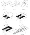
- FIGS. 1 a - 1 gthe steps of fabricating a preferred package 10 of the present invention is demonstrated.
- a portion of a thin film cut to shape and sizeis demonstrated 11 .
- the film 11can be made of mono layer or multi-layer plastic, metal, metal oxides, glass or a combination thereof. Other film materials known in the art are applicable.
- FIG. 1 bdemonstrates the film portion 11 after a fitting 12 has been attached to it on a folding line 19 .
- the fitting 12is preferably made of plastic material and is attached to the film 11 by one of the means known in the art including heat stake welding, ultrasonic welding, RF welding, hot plate welding, adhesives, or mechanical engagement such as snap feature or pressure fit to a member located of the opposite side of the film 11 .
- FIG. 1 cdemonstrates a step in the fabrication of the package 10 where two panels of the film 11 are folded along the folding line 19 . The film 11 adjusts itself to accommodate the rigid fitting along the folding line 19 .
- FIG. 1 ddemonstrates a fabrication step of the package 11 where a first compartment 15 is formed by welding a defined area 14 of the film 11 between the two opposite folded sides. The geometry of the welding 14 allows for the film portion 13 around the fitting 12 to naturally blend in with compartment 15 .
- FIG. 1 edemonstrates a subsequent step in the fabrication of the package 11 where the first compartment 15 has been filled and sealed and a second compartment 16 has been formed.
- the sealing portion 17 between the first compartment 15 and the second compartment 16is frangible such that under the presence of pressure in at least one of the compartments 15 or 16 the attachment of the opposite walls in designated portion 17 will separate (or rupture) allowing said two compartments to merge, while the perimeter sealing of the compartments 15 and 16 remains tightly sealed.
- FIG. 1 fdemonstrates a subsequent step of fabricating the package 11 where the second compartment is sealed resulting in a completely hermetically sealed package. Unlike most of the film packages with fitment which are commercially available, where the fitting is inserted between the film walls which construct the compartment and therefore are in direct contact with the content of the package, the content of compartments 15 and 16 are solely exposed to the film 11 inner layer providing a superior barrier from environmental conditions.
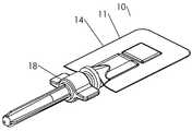
- FIG. 1 gdemonstrates a subsequent stage of the fabrication of the device 10 where a dispensing assembly 18 is attached to the fitting 12 .
- the dispensing assemblyalso referred to in this embodiment and others as an administration assembly, moves relative to the sealed package and communicates the content of the package to the target to which the content is ultimately applied.
- a couplersuch as a fitting or fitment, joins the administration assembly to the sealed package.
- the administration assemblyincludes a delivery device, and it comprises a proximal end including at least one mean for communicating the content of the package to the dispensing assembly in a sealed fashion; and a distal end comprising at least one applicator for the particular application of the device.
- the applicatoris a canula or a needle for invasive administration of the contents of the package to a tissue of a subject such as intradermal injection, subcutaneous injection, intramuscular injection or other injection methods known in the art for medical, cosmetic, veterinary, or other commercial dispensing applications.
- the applicatoris a dropper tip or a spray head for topical applications, oral applications, enteral applications, parenteral applications, opthalmological applications, nasal, or ear treatment or other medical, veterinarian, cosmetic, beauty or commercial applications known in the art.
- the applicatoris a surface applicator such as a brush, pad, sponge for one of the applications described above.
- the dispensing assemblycomprises a connector or a fitting to connect to any of the above applicators or to connect to a tube or a bag to which the content of the package is to be dispensed.
- Commercial applicationsinclude dispensing of glue, paint or dyes or samples of such, chemical agents for diagnostic or titration, glues, or other commercial applications known in the art. It will be obvious to those skilled in the art that dispensing assembly may include plurality of applicators or a replaceable applicator.
- FIGS. 2 a - 2 ga preferred embodiment of the present invention is demonstrated.
- FIGS. 2 a and 2 bshow general views at the pre-administration (or rest) position, i.e. the position in which the device is during storage, transportation and until it is used.
- the pouch 11has the fashion as demonstrated in FIG. 1 , and an elongated fitting 12 , broadly a coupler, is attached to the pouch along the folded section of the pouch 19 .
- a needle protector 21is accommodated at the distal end of the fitment 12 .
- the first compartment 15is separated from the second compartment 16 by a frangible seal 17 .
- FIG. 2 cdemonstrates a section view along the section line in FIG.
- FIG. 2 areveals a needle 22 having a distal sharp end to facilitate penetration of the needle to the body of a subject, and a proximal end for piercing the pouch 11 in order to establish fluid communication between the needle 22 and the fluid in the reservoir 15 .
- FIG. 2 ddemonstrates the device after the first and the second compartment were merged and its contents mixed such that the fluid in the reservoir 15 is now ready for administration.
- FIG. 2 edemonstrates an enlarged detail view of a portion of FIG. 2 c .
- the needle 22passes through a needle hub 23 which is frictionally held within the fitting 12 . It is to be noted that needle 22 has a sharpened inner end portion 20 for penetrating the of pouch 11 and a sharpened outer end portion for use in administering the drug or vaccine to a subject.
- a needle protector 21 having a diameter such that it can fit within fitting 12is, for storage and shipment, lodged with its open end fitting within the open end of fitting 12 and held in position by a combination of friction and an inwardly projecting annular ridge which abuts hub 23 .
- Needle protector 21functions as an actuator for advancing the needle from the pre-administration position toward the ready position.
- Protectorincludes an outwardly projecting flange 25 to control the movement when preparing to administer the solution by forcing needle to breach the integrity of the pouch's 11 wall.
- the deviceis shown in the ready position after the needle protector 21 was pushed toward the fitting 12 thereby manipulating the proximal sharp point of needle 22 to penetrate the pouch wall 19 .
- the pierced portion of the wall 19establishes a fluid tight seal against the needle 22 thus ensuring that the medication flows strictly from the reservoir 15 to the distal end of the needle 22 .
- FIG. 2 gfollowing the piercing of the wall 19 the needle protector 21 is removed and can be retained for use as a protective cover over the needle 22 once the injection has been administered.
- FIGS. 3 a & 3 ba further preferred embodiment of the present invention is demonstrated which is mostly similar to the configuration of FIG. 2 except for the addition of a sealing member in a form of a gasket 31 disposed between the fitting 12 and the pouch's wall 19 to facilitate the sealing of the needle 22 to the reservoir wall 19 .
- the gasket 31is made from a resilient material compatible with the specific application and the manufacturing processes, and in most applications latex or silicone rubbers are adequate.
- the gasket 31is compressed either radially or axially or both to increase the compression of the gasket 31 on the needle 22 when the last penetrates thereby improving the sealing.
- FIG. 3 ademonstrates a detail of a section view exposing the piercing arrangement in the rest position.
- FIG. 3 bdemonstrates the device after the piercing mechanism has been activated: the needle protector is advanced toward the pouch 11 causing the needle hub to displace toward the hub and the needle 22 to penetrate the gasket 31 and the pouch wall 19 .
- FIGS. 4 a & 4 banother preferred embodiment of the present invention is demonstrated, which is mostly similar to the configuration of FIG. 2 with the exception that a different sealing mechanism between the needle 22 and the reservoir 15 is implemented.
- the fitting 12comprise a narrow section 41 that press fits against the needle 22 in a fluid tight seal fashion.
- the piercing mechanismis similar to that of the configuration of FIG. 2 .
- FIG. 4 ademonstrates the rest position
- FIG. 4 bdemonstrates the pierced position.
- annular reinforcement insert 51supports the inside of the pouch wall 19 , thereby to: a) reduce the tendency of the wall 19 to stretch downwardly during piercing, b) provide a rigid backing for compressing the gasket 31 against fitting 12 , c) provide a protection to the sharp piercing end of the needle from getting in contact with the pouch walls 11 .
- the insert 51can be made from thermoplastic material such as polypropylene or polyethylene and is attached to the inside of the wall 19 by one of the suitable means known in the art such as heat welding or gluing.
- FIG. 6demonstrates another preferred embodiment where the insert 51 and the fitting 12 are attached to the wall 19 through a mechanical engagement between the fitting 121 and the insert 51 through the wall 19 , potentially avoiding the direct attachment between the fitting and the wall 19 or the insert 51 and the wall 19 .
- a protrusion of the insert 51comprises a snap feature 61 , in the form of a lateral radial ridge, that is forced into a reciprocal recess with a radial lateral groove 62 in the fitment 12 .
- FIG. 7demonstrates another preferred sealing between the needle 22 and the reservoir 15 where a gasket 31 is accommodated between the insert 51 and the inside of the wall 19 .
- FIG. 8demonstrates a further preferred embodiment of the pouch of the present invention where the gasket 31 is implemented between the layers of the film wall 19 .
- FIG. 9 ademonstrates the rest position of the device 90 .
- the needle hubcomprises lateral protrusions 91 for facilitating the turning action with a finger and thumb.
- FIG. 9 bdemonstrates the device 90 when the pouch is pierced and the device is in a ready state for administration. After merging compartment 16 to compartment 15 and mixing their contents, the hub 23 is turned a quarter turn clockwise to pierce the reservoir wall 19 , and thereafter the needle protector 21 is removed making the device ready for administration.
- FIG. 9 cdemonstrates a detailed section view of the piercing mechanism of the device 90 at the rest position.
- the hub 23comprises an internal threaded bore 92 , engaged with external threads 93 on the fitting 12 .
- FIG. 9 ddemonstrates the same view as FIG. 9 c after the hub 23 has been turned clockwise, causing the hub 23 to travel axially toward the pouch 11 and the needle 22 to pierce the pouch wall 19 .
- FIGS. 10 a & 10 bdemonstrate another preferred embodiment of the present invention comprising an automatic piercing mechanism which is activated at the removal of the protector 21 .
- a compressed coil spring 101is accommodated between the distal end of the fitting 12 and the needle hub 23 biasing the needle hub 23 toward the pouch 11 , yet the hub is retained in a offset position from the pouch by detent arms 102 .
- Detent arms 102have the form of cantilever springs and their tapered contact surface with the hub 23 apply an outward radial force on the arms 102 to disengage from the hub 23 .
- the detent arms 102are counter-forced inward by the protector 21 . Referring to FIG.
- the cantilever arms 102are free to move outward by the force applied by the hub 23 , thereby disengaging from the hub 23 .
- the hub 23under the force of the spring 101 advances toward the pouch 11 causing the needle to pierce the wall 19 .
- FIGS. 11 a - 11 edemonstrate a further preferred embodiment of the present invention comprising a needle stick safety feature and automatic piercing feature.
- FIG. 11 ademonstrates a perspective view of the device comprising the pouch 11 , a fitment 12 having a cover 112 with a mostly longitudinal slot 113 in which a slider knob 111 is disposed and can be operated to travel along said slot to manipulate the needle to the administration extended position, and for piercing the wall of the pouch.
- Protrusions 118 of the knob 111lean against surface 112 preventing the knob from rotating when operated, except when the protrusions 118 reach the broadening in the slot 117 .
- FIG. 11 ademonstrates a perspective view of the device comprising the pouch 11 , a fitment 12 having a cover 112 with a mostly longitudinal slot 113 in which a slider knob 111 is disposed and can be operated to travel along said slot to manipulate the needle to the administration extended position, and for piercing the wall of the pouch.
- the fitting 12comprises a pouch piercing hub 114 and an elongated body in which the needle 22 is disposed, its distal end accommodated in an opening 115 of the fitting 12 and it is attached to the slider 111 next to a bend in the needle 22 , while its proximal (piercing end) is free.
- the device 110is demonstrated at an intermediate instant of the activation action, it being understood at this point that one or more of the compartments, e.g., compartment 16 , has been depressed to merge their contents.
- compartment 16was merged with compartment 15 , and the fluids in the extended compartment 115 were mixed and ready for administration, the tamper evident piece 114 is broken-off and the knob is operated to advance the needle 22 to extend from the fitting 12 .
- the operation of the knob 111is achieved by placing the finger on the pad 116 , the thumb on slider knob 111 and squeezing the knob 111 forward.
- the knob 111slides forward until it hits the end of the slot 113 , at which point protrusions 118 are aligned with the broadening zone 117 of the slot 113 .
- FIG. 11 dthe end position of the knob 111 outward operation is demonstrated in which, under continuation of squeezing the knob forward, the knob 111 tilts counterclockwise thereby causing the needle to bend and the proximal end of the needle to penetrate the piercing hub 114 and pierce the pouch 111 .
- the protrusions 118are engaged with the broadening zone 117 of the slot 113 , holding the knob (and the needle) from moving along the slot 113 during administration.
- the knob 111is detained in the rotated position by a pair of detent protrusions (not shown) that engage in the slot 113 at the end of the knob rotation.
- the force that the needle applies to the knob due to its bendingis in a direction which causes a counterclockwise torque to the knob.
- Such arrangementare some times referred to a self locking mechanism, toggle mechanism, or over-center mechanism.
- the knob 111is manipulated back to the original position thereby disconnecting the needle 22 from the reservoir 15 and hiding the distal end of the needle 22 in the fitting 12 .
- a compressed springis disposed in the fitting 12 along its longitudinal direction such that it biases the knob 111 to the rest position, causing the knob 111 to return to the backward position as soon as the knob 111 has been rotated back from the administration position.
- FIG. 11 edemonstrates the position of the device after the knob has been retracted to the rear most position.
- the knob 111retracts to a further backward position than the rest position.
- the distal end of the needle 22disengages from the opening 115 such that any subsequent attempt to operate the knob to the extended position of the needle, is prevented as the needle hits the wall of the fitting 12 .
- a constant tension on the needle 22ensures that the needle 22 tip will be removed sidewards from the opening 115 .
- FIGS. 12 a - 12 ea further preferred embodiment of the present invention is demonstrated where a device for facilitating the squeezing of the reservoir for administration is provided.
- FIG. 12 ademonstrates a device 120 at the rest position, comprising a pouch 11 which holds a hermetically sealed reservoir 15 , and a fitting 12 attached to said pouch 11 confining the pouch's piercing hub (not shown) and a proximal end of a needle 22 for piercing said pouch.
- the devicefurther comprises a protector having a core 123 firmly connected to the fitting 12 and two rotatable hoods 122 , connected to the core 123 by living hinges 126 , which cover the distal end of the needle, thus forming a protection from accidental needle stick injuries.
- a groove 125defines a cantilever surface 124 which at a later position will be used as a compression panel for squeezing the reservoir 15 to cause the fluid in said reservoir 15 to expel.
- FIG. 12 bdemonstrates a section view of the device 120 at the rest position.
- the needle 22is positioned such that the proximal end of the needle is offset from the gasket 31 .
- the needle hub 23can be reached through opening 127 at the base of the hoods 122 to operate the needle hub 23 to pierce the pouch.
- FIG. 12 cwhich demonstrates a variation on the needle hub 23 which here comprises two vertical arms that prevent the hoods 122 from opening unless the hub 23 has been manipulated down to pierce the pouch, thereby determining the sequence in which the device is to be operated.
- the device 120is demonstrated at intermediate instant of opening the hoods 122 in a disengaged state. Where the needle hub 23 has not been operated at an earlier stage to pierce the pouch 11 , a clear access to the needle hub 23 allows making the piercing operation at this stage. Referring now to FIG.
- a section viewdemonstrates the device 120 ready for administration.
- the hoods 122has been fully opened such that the compression panels 124 are leaning against the reservoir 15 in an engaged state and the internal side of the cantilever surfaces 124 are used as squeezing pads. Squeezing the reservoir 15 with the compression panels allows convenient and efficient means for completely emptying the reservoir 15 , especially if the last has a surface larger than the finger pads 128 .
- the hoodsare returned to the rest position to protect for accidental needle injuries.
- the current embodimentprovides improved needle-sticks safety compared with embodiments where a protector is replaced on the needle after use in the axial direction of the needle. In this embodiment the protector panels are pushed from the sides in a manner that the fingers are not exposed to needle sticks
- a tamper evident featureshowing whether the device has been previously tampered with, needs to be manipulated in order to open the hoods 122 .
- a tamper evident featureis manipulated by opening the hoods 122 .
- a tamper evident featureneeds to be manipulated in order to operate the hub 23 to pierce the pouch 11 .
- the operation of the hub 23 to pierce the pouch 11manipulates a tamper evident feature.
- a lock featurepermanently locks the hoods together when those are returned to the rest position after administration providing an auto-disable feature preventing reuse of the device.
- FIGS. 13 a - 13 fa further preferred embodiment is demonstrated which is mostly similar to the embodiment 120 of FIG. 12 , with the exception that an automatic piercing mechanism is incorporated in the needle protector.
- FIG. 13 aand its enlarged detail view in FIG. 13 b , demonstrate the device 130 in the rest position
- a cylindrical sleeve 131is accommodated concentric with the needle 22 , and spaced apart from needle hub 23 .
- the sleeve 131is connected to two joint arms 132 at one end of the joint arms.
- the other end of the joint arms 132are connected to the hoods 122 , and at the rest positioned the arms are folded and confined between the sleeve 131 and the hoods 122 .
- FIG. 13 cand its enlarged detail view in FIG. 13 d , demonstrate the device 130 at intermediate instant of opening the hoods 122 .
- the end of the arms 132 that are connected to the hoods 122are pulled out with the hoods, causing the sleeve 131 to move toward, and get in contact with, the needle hub 23 .
- FIG. 13 eand its enlarged detail view 13 f , demonstrate a subsequent instant of opening the hoods 122 .
- the arms 132continue to pull the sleeve 131 down as the hoods continue to open, and as a consequence the sleeve displaces the hub 23 toward the pouch 11 causing the needle 22 to pierce the wall 19 .
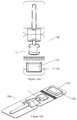
- FIGS. 14 a - 14 idemonstrate a further preferred embodiment 140 of the present invention.
- FIG. 14 ademonstrates a general view of the device 140 at a pre-use configuration.
- the film 11 that constitutes the pouchcontinues beyond the piercing hub to cover and hermetically seal over the needle protector, such that the entire device is hermetically sealed and the protector can not just be pulled of from the device 140 .
- a slit 147 in the filmmarks the future point of breaking-off the protector and part of the film from the device 140 .
- FIG. 14 bdemonstrates the piercing hub 141 and the protector 142 , which confine the needle (not shown), prior to introducing to the pouch 11 .
- FIG. 14 cdemonstrates an exploded view of the assembly of FIG. 14 b .
- the needle 22 , and the needle hub 23are now visible.
- the needle hub 23comprises an external thread section 144 that engages with an internal thread section of the piercing hub 141 , and a flange section 145 that engages with the needle protector 142 when the last in mounted on the needle hub 23 .
- FIG. 14 ddemonstrates the device 140 when the protector and the section of the pouch film that cover it are turned a quarter turn counterclockwise.
- FIG. 14 fdemonstrates the device in the rest position again providing orientation for the following section views.
- FIG. 14 gorients for the detail view of FIG. 14 h .
- the thread section 144 of the needle hub 23is engaged with the internal thread 146 of the fitting 141 such that when the needle hub is rotated in a counterclockwise direction the needle hub 23 will advance toward the pouch 11 .
- the flange section 145 of the needle hub 23is engaged with needle protector base 152 such that turning the protector around the needle 22 axis will turn the needle hub along with it, while the needle hub 22 is free to move outward from the protector base 152 along the needle 22 axis.
- the protector 21is turned a quarter turn counterclockwise to shear the film package the needle 22 will advance toward the pouch 11 .
- FIG. 14 hfurther shows a thin membrane that seals the reservoir 15 .
- FIG. 14 ishows a section view of the same configuration as in FIG. 14 d , after the protector 21 has been turned a quarter turn in a counterclockwise direction from the rest position. The turn of the protector 21 caused the needle hub 23 to turn and advance out of the protector base 152 and toward the pouch 11 causing the proximal needle end to pierce the membrane 148 .
- FIGS. 15 a - 15 bdemonstrate a further preferred configuration of the present invention which comprises a compartment for disinfectant substance for disinfecting the skin area at the injection site.
- the pouchcomprises a dedicated slit 152 for concentrating the shear forces when opening the disinfectant compartment 151 .
- the disinfectant compartment 151may contain a liquid, a gel, or other forms of disinfectant ingredients.
- the pouchmay further contain a gauze, a sponge, or any other absorbing matrix known in the art that can contain the disinfectant fluid and facilitate the application to the skin at the injection site.
- the arrangementis such that the essential steps for preparing the device for administration are conditioned by or are interfered by first utilizing or at least removing or opening the disinfectant compartment 151 .
- FIGS. 16 a - 16 idemonstrate a further preferred embodiment where the fitting is accommodated on a welded seam of the pouch.
- FIG. 16 ademonstrates a section view for orientation of the following section views.
- FIG. 16 bdemonstrates the rest position.
- the fitting 12is mechanically engaged with an insert 51 through the wall of the pouch 11 .
- the needle hub 23is accommodated in a vertical slot 153 in the fitting 12 , such that the needle is offset from the seam line of the pouch 11 and is aligned with a conduit 151 in the insert 51 .
- FIG. 16 cwhen the needle hub is advanced in the slot 153 toward the pouch, the needle 22 pierces the wall of the pouch 19 .
- FIG. 17 ashows the device 170 in a perspective view.
- the device 170comprises a housing 171 and a sliding knob 172 accommodated in sliding grooves (not shown) in the housing 171 .
- the package 11is accommodated on the top surface of the housing 11 and comprises a first compartment 15 and a second compartment 16 , separated by a rupturable seal 17 (not shown).
- the housing 171conceals a needle assembly which can be extended through opening 173 when activating the device 170 .
- the sliding knob 172comprises two sets of two teeth 174 and 175 symmetrically disposed along the front edge of the knob 172 . It can be appreciated that in this Figure and in the following FIGS. 18 , 19 , and 20 , the housing acts as the coupler and the sliding knob acts as the actuator.
- FIG. 17 bdemonstrates a top view of the device 170 .
- the viewprovides three section lines for orientation of the subsequent section views.
- Two sets of two openings, symmetrically disposed in the top of the housing 176 and 177are designated to accept teeth 175 and 174 respectively, when the knob is advanced to a forward position where said teeth and said openings align.
- FIG. 17 cdemonstrates a longitudinal section cut of the device 170 at the rest position in proximity to the side wall of the housing 171 .
- the knob 172is shown in its entirety and not sectioned, to better demonstrate the details of this part and their interaction with the device 170 .
- the knob 172comprise a first surface 172 ′ in parallel and in contact with the top surface of the housing 171 and an inclined surface 172 ′′ (hereafter “compression panel”) in the front of the knob on which the teeth 174 , 175 are disposed.
- compression panelinclined surface 172 ′′
- the knob 172further comprises two vertical ribs 177 , engaged in longitudinal grooves in the top of housing 171 , each rib 177 comprises a lateral protruding pivot 179 , perpendicular to said rib 177 , and a latch 178 provided by a notch in the rib 177 .
- the pivot 179contacts the inside of the upper wall of the housing 171 .
- a meniscus 185 in the side wall of the housing 171defines the forward end position of the pivot 179 when the knob 172 is slid forward, at which position the teeth 174 will align with opening 177 allowing the knob 172 to rotate.
- a needle 22connected to a needle hub 23 , are disposed in the housing 171 such that they can be moved along the longitudinal direction of the housing 171 .
- the needle 22is accommodated in a slit in the needle hub 23 and is connected by one of the means known in the art such as press fit or glue.
- a spring 181is disposed between the housing 171 and the needle hub 23 , biasing the last to the backside of the housing 171 .
- the needle 22comprises a sharp distal end 22 ′ for penetrating a tissue of a subject, accommodated in an opening portion of the housing 173 , and a sharp proximal end 22 ′′ at the end of a hooked section of the needle 22 for piercing the compartment 15 .
- the package 11comprises a first compartment 15 and a second compartment 16 defined between two opposite film walls, and separated by a rupturable welded portion between said walls, and is attached to the front section of the upper wall of the housing 171 .
- the package 11is attached to the housing 171 by one of the means known in the art including, welding, gluing, mechanical fit, adhesive layer of the film, etc.
- the first compartment 15comprises a well 186 extending through an opening in the upper wall of the housing 171 to the inner side of the housing 171 .
- a co annular cylinder member 187is disposed in the well to improve the sealing against the needle 22 when it pierces the wall of the compartment 15 .
- the hub 23comprises a detent tooth 182 which is engaged with the latch 178 of the knob 172 , such that when the knob 172 is moved along the housing 171 the needle hub 23 and the needle 22 will be traveling along with it.
- the needle hub 23further comprises a snap arm 183 aligned, and in an offset position from opening 176 , which comprises an inward protrusion 184 for latching snap arm 183 when the needle hub 23 travels to its forward position.
- FIGS. 18 a - 18 edemonstrate embodiment 170 of FIG. 17 in the ready position.
- the knob 172is forced by pushing forward the compression panel 172 ′′ with a finger to the forward position.
- FIG. 18 aprovides a general view of the device 170 with the needle 22 now extending from the housing 171 through opening 173 . Normally at this position the needle is inserted to a target tissue of a patient, which is not shown here.
- FIG. 18 bdemonstrates a top view of the device 170 providing orientation for the subsequent section views.
- the grooves 188 in the upper wall of the housing in which the ribs 177 (not shown) of the knob 172 engage,are now visible.
- a widening portion of the groove 188allows clearance for the pivots 179 to pass through the wall into the housing 171 during the assembly process.
- the teeth 174 of the knob 172aligns with opening 177 , such that forcing the second portion of the knob 172 ′′ further forward or downward will cause the knob to rotate counterclockwise.
- the sealing member 187provides for an improved sealing between the needle and the compartment's 15 wall.
- the sealing membercan be made from rubber materials such as silicone or polyurethane rubber, or a soft plastic material such as PE, a PE/EVA compound, etc. It will be obvious to those skilled in the art that the fluid tight sealing of the needle 22 to the wall 11 can be accomplished by other means. In one embodiments the composition of the actual wall of the package 11 is such that it provides good sealing.
- Such wallwill preferably have a layer of soft thermoplastic such as PE, EVA, Surlin (Dupont) etc.
- the sealing memberis accommodated externally to the package 11 wall.
- the sealing memberis provided by an inward extension of the upper wall of the housing 171 . Referring back to FIG. 18 d , by continuing to force the compression panel 172 ′′ forward (or downward), compartment 15 is depressed by causing the content of compartment 15 to expel through the needle 22 (i.e. the “administration” of the fluid), until the compartment is completely squeezed.
- the snap arms 183latch with the protrusion 184 of the opening 176 in the upper wall of the housing 171 . Due to its rocker construction, as the knob 172 is rotated to squeeze the compartment 15 , the latch 178 of the knob is removed from detent tooth 182 , thereby disengaging the knob 172 from the needle hub 172 . Thereafter, and for the duration of the administration, the needle hub 23 is held in the front position due to the engagement of snap arm 183 and protrusion 184 , preventing the spring from pushing the needle hub 23 back in.
- teeth 175penetrate through openings 176 and contact snap arm 183 pushing them down toward disengagement of protrusions 184 , such that as soon as the administration is completed, the snap arms 183 disengage from protrusions 184 , the hub 23 snaps to the backward most position drawing the needle back into the housing.
- FIG. 18 fdemonstrates the discard position of the device 170 .
- the hub 23is now retracted to a position where it can not reengage with the knob 172 , preventing reuse of the device 170 , or abuse of residual substance.
- the knobcan not be rotated back from the counterclockwise end position thereby preventing reach to the package 11 , thereby preventing potential exposure or abuse of the substance.
- FIGS. 19 a - 19 ea further preferred embodiment of the present invention is demonstrated which is mostly similar to embodiment of FIGS. 17 and 18 , but for a different method of piercing the package 11 .
- the general operation and function of the knob 172is similar to that of FIG. 17 and therefore will only be briefly described.
- FIG. 19 ademonstrates a general view of the device 190 .
- a U-shape groove 194 in the upper wall of the housing 191defines a cantilever portion 195 to which the package 11 is attached.
- FIG. 19 bprovides a top view of the device 190 for orientation of the section views in subsequent Figures.
- FIG. 19 cdemonstrates a section of the device 190 in the rest position.
- the first compartment 15comprises a well 186 that extends through an opening in the upper wall of the housing 191 .
- the proximal end of the needle 22 ′′terminates with a vertical section.
- FIG. 19 ddemonstrates the device after the second compartment 16 has been merged to the first compartment 15 , and the knob 172 has been moved to the forward position, by pushing on the compression panel 172 ′′ forward with a finger. The proximal end of the needle is now aligned with the well 186 of compartment 15 .
- compartment 15is depressed and as a result causes the cantilever surface 195 to bend down to a point that the proximal end of the needle 22 ′′ pierces the wall of compartment 15 , establishing fluid communication between the content of compartment 15 and the distal end of the needle 22 ′.
- the device 200is mostly similar to the device 190 of FIG. 19 but for the different piercing means.
- the device 200is demonstrated in the administration position.
- a u cut in the bottom wall of the housing 201defines a cantilever section 202 .
- To administer the content of compartment 15one finger presses the compression panel 172 ′′ while another finger provides for an opposite force on the cantilever section 202 , such that the cantilever section 202 bends in and forces the proximal end of the needle 22 ′′ to bend and pierce the wall of the first compartment 15 .
- a sealing member 205enhances the sealing of the wall of the well 186 of compartment 15 .
- the sealing member 205can be made of soft thermoplastic or rubber.
- FIGS. 21 a - 21 ha further preferred embodiment of the present invention is demonstrated.
- FIG. 21 aa perspective view is showing the upper side of the device 210 , shown in the rest position.
- the device 210comprises a mostly thin and flat body 211 with a general shape of a credit card divided into a first compression panel 215 and a second compression panel 216 (hereafter sometimes referred to as “panel” or “panels”), mostly similar in size to the first panel 215 , by a living hinge section 212 .
- the package 11is attached to the first panel 215 .
- FIG. 21 ba perspective view of the under side of the device 210 is demonstrated in the rest position.
- a needle 22 and a hub 23 assemblyis accommodated in a longitudinal recess 213 that extends between the first panel 215 and the second panel 216 , providing clearance for the hub 23 to slide toward the first panel 215 .
- the second panel 216comprises a slot 214 for accommodating the distal end of the needle (not seen), providing protection to the needle from being damaged prior to use, as well as from sticking injuries from the needle.
- the hub 23acts as the needle actuator.
- the actuatorcan be considered as any pieces which, collectively or separately, function to advance at least a portion of the administration assembly (or particularly, at least a portion of the delivery device) from the pre-administration position towards the ready position.
- the flat body 211acts as the coupler.
- a labelat least partially covers the lower surface of the first and second panels 215 , 216 .
- the labelis at least partially removable.
- said removable sectionprotects the needle during storage and is removed to expose the needle 22 prior to administration.
- said removable section of said labelprevents access to the needle hub 23 , and by removing said peelable section the hub 23 can be manipulated to move toward the first panel 215 .
- said removable section of said labelbridges between the first panel 215 and the second panel 216 , over the hinge 212 therefore preventing the body 211 from folding, and whereby removing said removable section allows for the body 211 to easily fold.
- a non-removable section of said labelretains the hub 23 in the slot 213 .
- the first compartment 15 of the package 11comprises a well 186 accommodated in a recess in the first compression panel 215 .
- the proximal end of the needle 22 ′′is accommodated in a horizontal bore 217 connecting the slot 213 and the well 186 , such that the sharp tip of the proximal end 22 ′′ is spaced apart from said well 186 .
- the content of the second compartment 16is powder that needs to be mixed and dissolved with a diluent in the first compartment 115 prior to being administrated.
- FIG. 21 ddemonstrates a section view along the line marked in FIG. 21 b .
- the hub 23is engaged with both compression panels 215 , 216 by an undercut such that the hub is limited to move in the longitudinal direction of the body 211 , preventing the panels from folding along the hinge 212 .
- Compartment 16has been merged into compartment 15 by separating the frangible weld line 17 .
- the hub 23has then been pushed toward the first panel 215 causing the proximal end of the needle 22 ′′ to pierce the wall of the well 186 of compartment 15 , thereby establishing fluid communication between the content of compartment 15 and the distal end of the needle 22 ′.
- the hubis now disengaged from the slot in the second panel 216 allowing the body 211 to be folded i.e. the second panel 216 to be folded over compression panel 215 or vice versa.
- the administration positionis demonstrated where the second panel 216 is folded over the first panel 215 thereby depressing compartment 15 and causing the content of said compartment to expel and to be administered through the needle 22 , to a target tissue of a subject (not shown).
- the distal end of the needle 22 ′is exposed and allows for penetration to a tissue.
- the order of the activation steps described abovecan be switched over.
- the slot 213 in the second panel 216does not have the undercut structure as demonstrated in FIG. 21 d and the second panel 216 folding is not constrained by the hub 23 . Therefore the second panel can be first folded over the first panel 215 and only then after the well hub is displaced to pierce the well 186 .
- the discarding position of the device 210is demonstrated.
- the second compression panel 216is rotated back 180 degrees around the hinge 212 to the opposite folded position of FIG. 21 f , and by doing so folding and destroying the needle 22 .
- a mechanical latchretains the device in this position, thus providing an auto-disable mechanism for preventing reuse of the device, as well as preventing possible accidental needle sticks after use.
- FIG. 21 hdemonstrates an enhancement which furnishes the hinge 212 with a toggle like action in a fashion commonly implemented in cosmetic or other flip-top liquid-container closures.
- Elastic straps 219are bridging between the first panel 215 and the second panel 216 of the body 211 , in an offset position to the folding axis of hinge 212 , such that the straps 219 are stretched in all the intermediate rotational positions between the end positions, and therefore biasing the second flap to one of the end positions demonstrated in the preceding figures.
- the toggle actionmay simplify the user's action of folding the second panel 216 .
- the device 210comprises a mechanism for causing automatic piercing of the reservoir when the compression panel is folded over similar to the mechanism disclosed in FIG. 13 .
- a rubber septum in a form of a sleeveis inserted into the section of the pouch that accepts the proximal end of the needle, to improve the sealing between the needle and the reservoir.
- FIGS. 22 a & 22 ba further preferred embodiment is demonstrated mostly similar to the embodiment of FIG. 21 , but for the hinge connecting between the first panel 215 and the second panel 216 .
- Panels 215 and 216are now fabricated as separated bodies, and are connected through a film layer that extends over a gap between the two panels, forming a live hinge 222 .
- said filmis an extension of one of the walls of package 11 .
- a pouch 231comprises an adhesive back is attached to the lower side of panels 215 and 216 preventing the body from folding.
- the pouchcontains a disinfectant substance that needs to be applied to the area where the needle is to stick.
- the disinfectant substancecan be in a form of liquid, gel, paste, loose in the pouch or absorbed in an absorbent matrix such as gauze.
- FIGS. 24 a & 24 bdemonstrate a further preferred embodiment of the present invention in which the first compartment 15 does not comprise a well and therefore is simpler to manufacture and assemble to the device 240 .
- the package 11is attached to an inclined surface relative to the needle 22 and the needle bore 217 such that the needle penetrates the package in an angle. It will be obvious to those skilled in the art that rather than positioning the package on an inclined surface the proximal end of the needle 22 ′′ can be guided in a shoot in the first panel 215 , such that during the displacement of the hub 23 , it will bend from a direction parallel to the wall of the package to an angle in which it will penetrate the package.
- FIG. 24 bdemonstrates how the finished package is assembled to the device assembly.
- the attachment of the package 11 in simple manner to the external wall of the mechanical device as is true for embodiment 17 to 24provides an advantageous means of manufacturing as the package 11 can thus fit pharmaceutical packaging machinery, and be manufactured faster and less expensively.
- the mechanical deviceon the other hand can be manufactured in a separate line or a separate facility. The package and the mechanical device can be then integrated in a third facility, or just prior to use, providing better manufacturing, storage, and logistic flexibility.
- FIGS. 25 a - 25 da method for producing a two compartment package is demonstrated.
- FIG. 25 aprior to filling, the seams of the two major walls are welded together except for opening areas which are left open for filling the compartments.
- the frangible seal 17is welded usually at a lower temperature than the seam welding.
- FIG. 25 bshows how the second compartment 16 filled and sealed.
- FIG. 25 cshows how the package 11 is turned upside down, preparing it for filling the first compartment 15 .
- FIG. 25 dshows how the second compartment has been filled and sealed. It will be obvious to those skilled in the art that the package 11 is preferably manufactured as strips articulating numerous packages 11 .
- FIG. 26demonstrates a filling from the side. Referring to FIG. 26 a , once again most of the contour of the package 11 is sealed prior to filling. FIG. 26 b demonstrates the package 11 when both compartments are filled and FIG. 26 b demonstrates the package 11 when both compartment are sealed.
Landscapes
- Health & Medical Sciences (AREA)
- Life Sciences & Earth Sciences (AREA)
- Veterinary Medicine (AREA)
- Public Health (AREA)
- General Health & Medical Sciences (AREA)
- Animal Behavior & Ethology (AREA)
- Anesthesiology (AREA)
- Hematology (AREA)
- Heart & Thoracic Surgery (AREA)
- Biomedical Technology (AREA)
- Engineering & Computer Science (AREA)
- Vascular Medicine (AREA)
- Pharmacology & Pharmacy (AREA)
- Medical Preparation Storing Or Oral Administration Devices (AREA)
- Infusion, Injection, And Reservoir Apparatuses (AREA)
Abstract
Description
Claims (16)
Priority Applications (1)
| Application Number | Priority Date | Filing Date | Title |
|---|---|---|---|
| US12/344,044US8663188B2 (en) | 2007-12-28 | 2008-12-24 | Dispenser and therapeutic package suitable for administering a therapeutic substance to a subject, along with method relating to same |
Applications Claiming Priority (2)
| Application Number | Priority Date | Filing Date | Title |
|---|---|---|---|
| US1736507P | 2007-12-28 | 2007-12-28 | |
| US12/344,044US8663188B2 (en) | 2007-12-28 | 2008-12-24 | Dispenser and therapeutic package suitable for administering a therapeutic substance to a subject, along with method relating to same |
Publications (2)
| Publication Number | Publication Date |
|---|---|
| US20090171311A1 US20090171311A1 (en) | 2009-07-02 |
| US8663188B2true US8663188B2 (en) | 2014-03-04 |
Family
ID=40799392
Family Applications (1)
| Application Number | Title | Priority Date | Filing Date |
|---|---|---|---|
| US12/344,044Active2031-04-13US8663188B2 (en) | 2007-12-28 | 2008-12-24 | Dispenser and therapeutic package suitable for administering a therapeutic substance to a subject, along with method relating to same |
Country Status (8)
| Country | Link |
|---|---|
| US (1) | US8663188B2 (en) |
| EP (1) | EP2240232A4 (en) |
| JP (1) | JP2011508634A (en) |
| CN (1) | CN101951988A (en) |
| AU (1) | AU2008345108A1 (en) |
| RU (1) | RU2010131797A (en) |
| WO (1) | WO2009086463A1 (en) |
| ZA (1) | ZA201005363B (en) |
Cited By (13)
| Publication number | Priority date | Publication date | Assignee | Title |
|---|---|---|---|---|
| US20140113239A1 (en)* | 2011-03-17 | 2014-04-24 | Marlène Abisdid | Self-lighting device for a cigarette |
| USD725264S1 (en)* | 2013-07-02 | 2015-03-24 | Adhezion Biomedical, Llc | Blistered dispenser |
| US9918900B2 (en) | 2014-10-29 | 2018-03-20 | R.P. Scherer Technologies, Llc | Inverse blow-fill-seal packaging |
| US10835678B2 (en) | 2015-07-02 | 2020-11-17 | Koska Family Limited | Single use delivery device prefilled with a reconstitutable agent |
| US11058825B2 (en) | 2015-11-27 | 2021-07-13 | Sanofi-Aventis Deutschland Gmbh | Cap for an injection device |
| US11382833B2 (en)* | 2016-04-25 | 2022-07-12 | Koska Family Limited | Systems and methods for fluid delivery |
| US11607369B2 (en) | 2017-11-17 | 2023-03-21 | Koska Family Limited | Systems and methods for fluid delivery manifolds |
| USD992110S1 (en) | 2021-08-10 | 2023-07-11 | Koska Family Limited | Sealed fluid container |
| US12005236B2 (en) | 2015-03-24 | 2024-06-11 | Kaleo, Inc. | Devices and methods for delivering a lyophilized medicament |
| US12017047B2 (en) | 2019-08-09 | 2024-06-25 | Kaleo, Inc. | Devices and methods for delivery of substances within a prefilled syringe |
| USD1052082S1 (en) | 2020-06-01 | 2024-11-19 | Koska Family Limited | Sealed fluid container |
| US12268847B1 (en) | 2021-02-10 | 2025-04-08 | Kaleo, Inc. | Devices and methods for delivery of substances within a medicament container |
| US12420016B2 (en) | 2011-01-26 | 2025-09-23 | Kaleo, Inc. | Medicament delivery devices for administration of a medicament within a prefilled syringe |
Families Citing this family (59)
| Publication number | Priority date | Publication date | Assignee | Title |
|---|---|---|---|---|
| WO2008097217A1 (en)* | 2007-02-07 | 2008-08-14 | Becton, Dickinson And Company | Safety shield system for a single use flexible-type compression syringe, and injection device |
| FR2949195B1 (en)* | 2009-08-24 | 2011-10-14 | Lfb Biomedicaments | STORAGE POUCH OF THERAPEUTIC SOLUTION |
| AU2010286439A1 (en)* | 2009-08-30 | 2012-04-19 | Aktivpak, Inc. | Dispensing device incorporating frangible section, along with dispensing method |
| US20110303703A1 (en)* | 2009-10-28 | 2011-12-15 | Yeager Don F | Apparatus for dispensing a controlled dose |
| US10350364B2 (en) | 2009-11-11 | 2019-07-16 | Windgap Medical, Inc. | Portable Drug Mixing and Delivery Device and Associated Methods |
| DE102010001506A1 (en) | 2010-02-02 | 2011-08-04 | Vosseler, Michael, 78073 | Dermal access device |
| US20110270220A1 (en)* | 2010-03-03 | 2011-11-03 | Aktivpak, Inc. | Linearly actuated dispenser and therapeutic package suitable for administering a therapeutic substance and related method |
| EP2637716B1 (en)* | 2010-11-08 | 2020-09-02 | Aktivax, Inc. | Beneficial agent dispenser |
| WO2012078696A2 (en)* | 2010-12-06 | 2012-06-14 | Aktivpak, Inc. | Aseptic cartridge and dispenser arrangement |
| CN103429287A (en)* | 2011-01-17 | 2013-12-04 | 阿克蒂夫帕克股份有限公司 | Aseptic cartridge and dispenser arrangement |
| WO2012099898A2 (en)* | 2011-01-17 | 2012-07-26 | Aktivpak, Inc. | Aseptic cartridge and dispenser arrangement |
| WO2012158973A2 (en)* | 2011-05-17 | 2012-11-22 | Aktivpak, Inc. | Filing system and methods for aseptic cartridge and dispenser arrangement |
| JP5990924B2 (en)* | 2012-02-13 | 2016-09-14 | 大日本印刷株式会社 | Packaging for chemicals |
| JP5942457B2 (en)* | 2012-02-13 | 2016-06-29 | 大日本印刷株式会社 | Packaging for chemicals |
| US20150209519A1 (en)* | 2012-08-14 | 2015-07-30 | Injector Aps | Disposable injector for injecting a liquid into a patient |
| IL221634A0 (en)* | 2012-08-26 | 2012-12-31 | Medimop Medical Projects Ltd | Universal drug vial adapter |
| EP2703029A1 (en)* | 2012-09-04 | 2014-03-05 | Sanofi-Aventis Deutschland GmbH | Medicament delivery device with alignment mechanism |
| JP6084408B2 (en)* | 2012-09-07 | 2017-02-22 | Hoya株式会社 | Surgical instruments |
| JP1628116S (en) | 2012-10-24 | 2019-04-01 | ||
| US20140322706A1 (en) | 2012-10-24 | 2014-10-30 | Jon Faiz Kayyem | Integrated multipelx target analysis |
| FR3002741B1 (en) | 2013-03-01 | 2016-01-08 | Transformation Des Elastomeres A Usages Medicaux Et Ind Soc D | NEEDLE PROTECTION DEVICE. |
| US10569017B2 (en) | 2013-03-15 | 2020-02-25 | Windgap Medical, Inc. | Portable drug mixing and delivery device and associated methods |
| US9907910B2 (en) | 2013-03-15 | 2018-03-06 | Windgap Medical, Inc. | Portable drug mixing and delivery device and associated methods |
| CN107866286A (en)* | 2013-03-15 | 2018-04-03 | 金马克诊断股份有限公司 | Systems, methods, and apparatus for manipulating deformable fluid containers |
| US10391262B2 (en) | 2014-03-18 | 2019-08-27 | Windgap Medical, Inc. | Removable actuating cap for use with an auto-injector assembly |
| JP6560187B2 (en)* | 2013-03-15 | 2019-08-14 | ウインドギャップ メディカル インコーポレイテッド | Portable drug mixing and delivery system and method |
| US20160074586A1 (en)* | 2013-05-02 | 2016-03-17 | Injector Aps | An injection device |
| PL2994062T3 (en)* | 2013-05-07 | 2020-05-18 | Auxin Surgery Sa | Device for chemically assisted dissection |
| EP2801335B1 (en)* | 2013-05-07 | 2018-03-14 | Ivoclar Vivadent AG | Syringe |
| US9498778B2 (en) | 2014-11-11 | 2016-11-22 | Genmark Diagnostics, Inc. | Instrument for processing cartridge for performing assays in a closed sample preparation and reaction system |
| USD881409S1 (en) | 2013-10-24 | 2020-04-14 | Genmark Diagnostics, Inc. | Biochip cartridge |
| ES2785219T3 (en) | 2013-11-14 | 2020-10-06 | Hahn Schickard Ges Fuer Angewandte Forschung E V | Access device |
| US9867951B2 (en)* | 2014-04-08 | 2018-01-16 | B. Braun Melsungen Ag | Hinged cap needle assemblies and related methods |
| US11116903B2 (en) | 2014-08-18 | 2021-09-14 | Windgap Medical, Inc | Compression seal for use with a liquid component storage vial of an auto-injector |
| CA2994803C (en) | 2014-08-18 | 2023-09-12 | Windgap Medical, Inc. | Portable drug mixing and delivery device and associated methods |
| US20160175544A1 (en)* | 2014-12-18 | 2016-06-23 | Marc Andrew Koska | Single use injection system |
| IL295010B1 (en)* | 2015-03-10 | 2025-06-01 | Regeneron Pharma | Pollution-free piercing system and method |
| US11730890B1 (en)* | 2020-01-07 | 2023-08-22 | Gholam A. Peyman | Plungerless aspiration and/or injection device and method using the same |
| US12023471B1 (en) | 2020-01-07 | 2024-07-02 | Gholam A. Peyman | Plungerless aspiration and/or injection device and method using the same |
| CN104906666A (en)* | 2015-06-30 | 2015-09-16 | 成都凯裕电子电器有限公司 | Safe syringe needle preventing cross infection |
| CA2994300C (en) | 2015-08-13 | 2023-12-05 | Windgap Medical, Inc. | Mixing and injection device with sterility features |
| WO2017089271A1 (en)* | 2015-11-27 | 2017-06-01 | Sanofi-Aventis Deutschland Gmbh | Medicament injection device |
| CN119950880A (en) | 2017-05-05 | 2025-05-09 | 里珍纳龙药品有限公司 | Auto-injectors and related methods of use |
| GB2565049B (en)* | 2017-07-27 | 2020-06-10 | Reckitt Benckiser Health Ltd | A head assembly of a dermaplaning device |
| US11291802B2 (en) | 2017-10-09 | 2022-04-05 | Becton, Dickinson And Company | Fluid storage unit, systems, and methods for catheter priming |
| GB2570722A (en) | 2018-02-06 | 2019-08-07 | Owen Mumford Ltd | Medicament delivery devices |
| GB2570721A (en) | 2018-02-06 | 2019-08-07 | Owen Mumford Ltd | Medicament packaging assembly |
| AU201816808S (en)* | 2018-05-22 | 2018-12-13 | Oxford Nanopore Tech Ltd | Analyses device |
| AU201816807S (en)* | 2018-05-22 | 2018-12-13 | Oxford Nanopore Tech Ltd | Analyses device |
| KR102708626B1 (en)* | 2018-06-20 | 2024-09-20 | 코스카 패밀리 리미티드 | Systems and methods for delivering dual component drug formulations |
| IT201800009131A1 (en)* | 2018-10-03 | 2020-04-03 | Orofino Pharmaceuticals Group Srl | Deformable cartridge for injection device |
| JP6527631B1 (en)* | 2018-12-05 | 2019-06-05 | イーエヌ大塚製薬株式会社 | connector |
| CN113242743A (en)* | 2018-12-19 | 2021-08-10 | 赛诺菲 | Plastic primary package for an injection device |
| US20220330931A1 (en)* | 2019-08-30 | 2022-10-20 | RevBio, Inc. | Formulation and packaging of compositions |
| CN115361983A (en)* | 2020-04-05 | 2022-11-18 | 科斯卡家族有限公司 | Systems and methods for prefilled medical delivery devices |
| WO2023018840A1 (en)* | 2021-08-10 | 2023-02-16 | Koska Family Limited | Pre-filled medical delivery assembly with a needle shield |
| WO2023034826A1 (en)* | 2021-08-31 | 2023-03-09 | Aktivax, Inc. | Packaging arrangement for a beneficial agent |
| USD1007676S1 (en) | 2021-11-16 | 2023-12-12 | Regeneron Pharmaceuticals, Inc. | Wearable autoinjector |
| CN118079210A (en)* | 2023-09-28 | 2024-05-28 | 立生医药(苏州)有限公司 | Nasal cavity soft fog drug delivery device, method and application |
Citations (126)
| Publication number | Priority date | Publication date | Assignee | Title |
|---|---|---|---|---|
| GB697643A (en) | 1948-05-29 | 1953-09-30 | Norton George Hein Jr | Injection assembly |
| FR1065305A (en) | 1952-06-25 | 1954-05-24 | Improvements in the execution of unitary containers in flexible materials for various substances | |
| US2743724A (en) | 1952-01-07 | 1956-05-01 | Rijks Inst Voor De Volksgezond | Injection apparatus |
| FR1121237A (en) | 1955-03-22 | 1956-07-25 | Hypodermic injector | |
| GB770341A (en) | 1954-11-18 | 1957-03-20 | Russell Paul Dunmire | Hypodermic syringe |
| US2794437A (en) | 1954-06-01 | 1957-06-04 | Joseph A Rosenberg | Sealed package |
| US3074544A (en) | 1958-12-22 | 1963-01-22 | Minnesota Mining & Mfg | Combination package |
| US3315801A (en) | 1964-05-18 | 1967-04-25 | Lowry Dev Corp | Dispenser package |
| US3387609A (en) | 1966-01-19 | 1968-06-11 | Walter A. Shields | Closure cap for disposable hypodermic syringes |
| US3521805A (en) | 1968-09-27 | 1970-07-28 | Anderson Bros Mfg Co | Dispensing packet |
| US3554256A (en) | 1968-11-08 | 1971-01-12 | Dave Champman Goldsmith & Yama | Flexible intravenous container |
| US3608709A (en) | 1969-09-08 | 1971-09-28 | Wayne Rogers V | Multiple compartment package |
| US3635376A (en) | 1970-06-05 | 1972-01-18 | Hellstrom Harold R | Quick-open flexible package |
| US3741384A (en) | 1971-12-03 | 1973-06-26 | Cloud Machine Corp | Individual sprinkle-packet with ribbed break-open neck |
| US3749620A (en) | 1969-11-20 | 1973-07-31 | American Cyanamid Co | Package for plural reactable components with rupturable ultrasonic seal |
| US3946732A (en) | 1973-08-08 | 1976-03-30 | Ampoules, Inc. | Two-chamber mixing syringe |
| US3968872A (en) | 1973-08-03 | 1976-07-13 | Sigma-Tau | Device, provided with a puncher and a dripper, for the hermetic sealing of containers |
| US3986640A (en) | 1973-08-20 | 1976-10-19 | Sanford Redmond | Package for a flowable product and material for making such package |
| US4011949A (en) | 1975-06-18 | 1977-03-15 | The Lehigh Press, Inc. | Package construction for opening only by a predetermined procedure |
| US4020836A (en) | 1975-05-14 | 1977-05-03 | James Robert Cunningham | Apparatus for medical injections |
| DE2647166A1 (en) | 1975-10-24 | 1977-05-05 | Ziristor Ab | LAMINATED PACKAGING MATERIAL AND METHOD OF MANUFACTURING THEREOF |
| US4051851A (en) | 1976-03-31 | 1977-10-04 | Tischlinger Edward A | Diaphragm assembly for a medicament dispensing unit |
| US4072149A (en) | 1976-08-09 | 1978-02-07 | Tischlinger Edward A | Nose cap and diaphragm assembly for injector |
| US4078565A (en) | 1976-10-04 | 1978-03-14 | Abbott Laboratories | Readily activated hypodermic syringe |
| US4084718A (en) | 1977-02-28 | 1978-04-18 | Varian Associates, Inc. | Compression seal for elastomeric septum |
| US4084588A (en) | 1976-03-19 | 1978-04-18 | Sherwood Medical Industries Inc. | Parenteral drug storage device with closure piercing coupling member |
| US4140409A (en) | 1977-09-02 | 1979-02-20 | Baxter Travenol Laboratories, Inc. | Disposable liquid applicator |
| US4236652A (en) | 1979-03-20 | 1980-12-02 | American Can Company | Dispenser package |
| DE2751078C3 (en) | 1977-11-15 | 1981-10-22 | Ludwig Dipl.-Ing. Dr. 8081 Eching Blasy | Container for flowable materials |
| US4411659A (en)* | 1982-03-16 | 1983-10-25 | Hollister Incorporated | Drainable collection pouch and filter assembly therefor |
| US4430013A (en) | 1979-07-23 | 1984-02-07 | Kaufman Jack W | Disposable swab article |
| US4441659A (en) | 1979-11-30 | 1984-04-10 | Marklund Olle E | Arrangement in drum mills |
| US4479989A (en) | 1982-12-02 | 1984-10-30 | Cutter Laboratories, Inc. | Flexible container material |
| US4493574A (en) | 1982-11-18 | 1985-01-15 | Sanford Redmond | Dispenser package having fault line protrusion |
| US4548601A (en) | 1984-04-09 | 1985-10-22 | Lary Banning G | Prepackaged, injectable pharmaceutical and hypodermic needle combination |
| US4602910A (en) | 1984-02-28 | 1986-07-29 | Larkin Mark E | Compartmented flexible solution container |
| US4608043A (en) | 1984-06-22 | 1986-08-26 | Abbott Laboratories | I.V. fluid storage and mixing system |
| US4611715A (en) | 1984-10-16 | 1986-09-16 | Sanford Redmond | Dispenser package |
| EP0088731B1 (en) | 1982-03-05 | 1986-11-26 | C O D Inter Techniques SA | Valve for the escape of vapour from a container |
| EP0088730B1 (en) | 1982-03-05 | 1986-12-10 | C O D Inter Techniques SA | A sealed foil cover on a container to form a detachable lid |
| US4648506A (en) | 1985-09-06 | 1987-03-10 | Land O'lakes, Inc. | Package with spreader for spreadable material |
| US4691495A (en) | 1985-07-20 | 1987-09-08 | The Mead Corporation | Product retard device for drop-loading packaging machine |
| US4724982A (en) | 1986-12-18 | 1988-02-16 | Sanford Redmond | Asymmetric stress concentrator for a dispenser package |
| US4819406A (en) | 1987-09-25 | 1989-04-11 | Sanford Redmond Inc. | Compact form-fill-seal machine for automatic production of sealed packages |
| US4871091A (en) | 1988-09-29 | 1989-10-03 | Mason-Keller Corporation | Disposable package for liquids |
| FR2633519A1 (en) | 1988-07-04 | 1990-01-05 | Soudant Jacques | SYRINGE COMPRISING A VARIABLE VOLUME CHAMBER BODY AND A NEEDLE ASSEMBLY DEVICE |
| US4955871A (en) | 1987-04-29 | 1990-09-11 | Path | Single-use disposable syringe |
| US4961495A (en) | 1988-06-10 | 1990-10-09 | Material Engineering Technology Laboratory, Incorporated | Plastic container having an easy-to-peel seal forming compartments |
| US5029718A (en) | 1988-09-01 | 1991-07-09 | Capsulit S.P.A. | Closure for bottles and the like comprising a reservoir with a breakable bottom |
| US5131760A (en) | 1990-07-03 | 1992-07-21 | Farmer Bert E | Packaging device |
| US5176634A (en)* | 1990-08-02 | 1993-01-05 | Mcgaw, Inc. | Flexible multiple compartment drug container |
| DE4203430A1 (en) | 1992-02-06 | 1993-08-12 | Value Design Studio Gmbh | Twin- layer packaging container for small goods - has several weakened lines in one layer allowing vertical opening without deformation |
| US5241150A (en) | 1989-10-02 | 1993-08-31 | Minnesota Mining And Manufacturing Company | Microwave food package |
| EP0370571B1 (en) | 1988-11-21 | 1993-10-06 | Holzer, Walter, Senator h.c. Dr.h.c.Ing. | Device for needle-less subcutaneous medicament injection |
| US5287961A (en) | 1992-10-23 | 1994-02-22 | W.R. Grace & Co.-Conn. | Multi-compartment package having improved partition strip |
| US5316400A (en) | 1991-12-19 | 1994-05-31 | Creative Products Resource, Inc. | Package systsem for flowable or solid substances |
| US5368199A (en) | 1990-08-06 | 1994-11-29 | Loctite Corporation | Microwaveable hot melt dispenser |
| US5383851A (en) | 1992-07-24 | 1995-01-24 | Bioject Inc. | Needleless hypodermic injection device |
| US5395031A (en) | 1992-03-10 | 1995-03-07 | Redmond; Sanford | Stress concentrator aperture-forming means for sealed containers and packages |
| US5425447A (en) | 1992-11-06 | 1995-06-20 | S.I.F.Ra. Societa Italiana Farmaceutici Ravizza S.P.A. | Bag for containing at least two separate substances that are to be mixed |
| US5462526A (en) | 1993-09-15 | 1995-10-31 | Mcgaw, Inc. | Flexible, sterile container and method of making and using same |
| US5478337A (en)* | 1992-05-01 | 1995-12-26 | Otsuka Pharmaceutical Factory, Inc. | Medicine container |
| US5533412A (en) | 1993-07-07 | 1996-07-09 | Ic Sensors, Inc. | Pulsed thermal flow sensor system |
| US5543097A (en) | 1994-03-09 | 1996-08-06 | Fang; Ta-Yun | Methods for preparing polyacrylamide gels for electrophoretic analysis |
| US5616132A (en) | 1995-06-09 | 1997-04-01 | Subot, Inc. | Injection device |
| US5637087A (en) | 1995-03-22 | 1997-06-10 | Abbott Laboratories | Prefilled, two-constituent syringe |
| US5681291A (en) | 1992-11-19 | 1997-10-28 | Tebro S.A. | Disposable auto-injector for prefilled syringes |
| US5687550A (en) | 1994-11-03 | 1997-11-18 | Bernd Hansen | Blow molding sealed container system |
| US5716343A (en) | 1989-06-16 | 1998-02-10 | Science Incorporated | Fluid delivery apparatus |
| US5836922A (en) | 1995-06-21 | 1998-11-17 | Bernd Hansen | Container for delivery of flowable material |
| USRE35986E (en) | 1988-08-23 | 1998-12-08 | Meridian Medical Technologies, Inc. | Multiple chamber automatic injector |
| US5848991A (en) | 1990-12-13 | 1998-12-15 | Elan Medical Technologies Limited Athlone, Co. | Intradermal drug delivery device and method for intradermal delivery of drugs |
| US5884759A (en) | 1996-06-28 | 1999-03-23 | L'oreal | Device for separately storing at least two substances, for mixing them together, and for dispensing the mixture obtained thereby, and a method of manufacture |
| US5921962A (en) | 1995-10-11 | 1999-07-13 | Science Incorporated | Fluid delivery device with flow indicator and rate control |
| US5957895A (en) | 1998-02-20 | 1999-09-28 | Becton Dickinson And Company | Low-profile automatic injection device with self-emptying reservoir |
| US6007264A (en) | 1998-12-02 | 1999-12-28 | Felix Investments, Llc | Integral package applicator |
| US6017598A (en) | 1994-03-29 | 2000-01-25 | Fresenius Ag | Multilayer polymer film for a multichamber medical bag and process for fabrication thereof |
| US6041930A (en) | 1995-08-04 | 2000-03-28 | Thornton Trustee Company Ltd. | Breakable sachet |
| US6045534A (en) | 1997-10-27 | 2000-04-04 | Sarcos, Inc. | Disposable fluid injection module |
| US6086562A (en) | 1997-10-27 | 2000-07-11 | Sarcos, Inc. | Disposable automatic injection device |
| US6085942A (en) | 1996-02-02 | 2000-07-11 | Redmond; Sanford | Coffee creamer and other cups and tubs |
| US6148996A (en) | 1997-02-28 | 2000-11-21 | Bormioli Rocco & Figlio S.P.A. | Package for keeping products separate before use |
| US6171285B1 (en)* | 1999-10-06 | 2001-01-09 | R. Steven Johnson | Retractable syringe |
| DE10032937A1 (en) | 1999-07-16 | 2001-01-18 | Becton Dickinson Co | Medicament dispensing unit, comprises a reservoir containing a prescribed amount of a medicament, and an auxiliary device whose operation ensures that the entire contents of the reservoir are dispensed |
| US6203535B1 (en) | 1996-05-13 | 2001-03-20 | B. Braun Medical, Inc. | Method of making and using a flexible, multiple-compartment drug container |
| US6245056B1 (en) | 1999-02-12 | 2001-06-12 | Jack M. Walker | Safe intravenous infusion port injectors |
| US6258063B1 (en) | 1997-01-17 | 2001-07-10 | Roche Diagnostics Gmbh | Hypodermic injection system |
| US20010047162A1 (en) | 2000-02-17 | 2001-11-29 | Yasumi Yugari | Injection kit and injection device |
| WO2002005889A1 (en) | 2000-07-17 | 2002-01-24 | Becton, Dickinson And Company | Delivery device with microneedles for the transdermal administration of a substance |
| US6354603B1 (en) | 1998-03-07 | 2002-03-12 | Alain Villette | Sealing device for carpule |
| US6435341B1 (en) | 2000-08-31 | 2002-08-20 | Inge S.P.A. | Child proof sealing device for a container of substances to be kept separate up to their dispensing |
| US20020123740A1 (en) | 2000-11-09 | 2002-09-05 | Flaherty J. Christopher | Transcutaneous delivery means |
| US6530900B1 (en) | 1997-05-06 | 2003-03-11 | Elan Pharma International Limited | Drug delivery device |
| US20030080129A1 (en) | 2001-11-01 | 2003-05-01 | Hiroaki Takimoto | Small bag-shaped drug container |
| US6675660B1 (en) | 2002-07-31 | 2004-01-13 | Sandia National Laboratories | Composition pulse time-of-flight mass flow sensor |
| US6743211B1 (en) | 1999-11-23 | 2004-06-01 | Georgia Tech Research Corporation | Devices and methods for enhanced microneedle penetration of biological barriers |
| US6781171B2 (en) | 2002-07-19 | 2004-08-24 | Dongbu Electronics Co., Ltd. | Pinned photodiode for a CMOS image sensor and fabricating method thereof |
| US6780171B2 (en) | 2002-04-02 | 2004-08-24 | Becton, Dickinson And Company | Intradermal delivery device |
| US6805998B2 (en) | 2000-03-24 | 2004-10-19 | Cymbet Corporation | Method and apparatus for integrated-battery devices |
| US20040240324A1 (en) | 2001-07-11 | 2004-12-02 | Reuben Isbitsky | Time indicator and method of manufacturing same |
| EP1201233B1 (en) | 2000-10-25 | 2004-12-08 | Euro-Celtique S.A. | Transdermal dosage form |
| US20040249339A1 (en) | 1998-12-18 | 2004-12-09 | Biovalve Technologies, Inc. | Injection devices |
| US20050004514A1 (en) | 1998-04-10 | 2005-01-06 | Hochman Mark N. | Drug infusion device with tissue identification using pressure sensing |
| WO2005002649A1 (en) | 2003-07-08 | 2005-01-13 | Novo Nordisk A/S | Portable drug delivery device having an encapsulated needle |
| US6906436B2 (en) | 2003-01-02 | 2005-06-14 | Cymbet Corporation | Solid state activity-activated battery device and method |
| US6979316B1 (en)* | 2002-05-23 | 2005-12-27 | Seedlings Life Science Ventures Llc | Apparatus and method for rapid auto-injection of medication |
| US6996951B2 (en) | 1996-05-13 | 2006-02-14 | B. Braun Medical Inc. | Flexible multi-compartment container with peelable seals and method for making same |
| US7004213B2 (en) | 2001-07-17 | 2006-02-28 | Bernd Hansen | Device for distributing substances |
| US7011650B2 (en) | 1999-09-09 | 2006-03-14 | Paradigm Medical, Llc | Multiple-dose syringe with collapsible container |
| US7025200B2 (en) | 2000-10-25 | 2006-04-11 | Lameplast S.P.A. | Bottle for two-component extemporaneous products |
| US20060079862A1 (en) | 2003-02-02 | 2006-04-13 | Amir Genosar | Drug infusion device |
| US7115108B2 (en) | 2002-04-02 | 2006-10-03 | Becton, Dickinson And Company | Method and device for intradermally delivering a substance |
| US7121409B1 (en) | 1999-09-02 | 2006-10-17 | Snap Pak Industries (Aust) Pty Ltd. | Dispensing sachet by bending and method of sachet manufacture |
| US20060276755A1 (en) | 2001-01-12 | 2006-12-07 | Becton, Dickinson And Company | Valved Delivery Device and Method |
| US20060283727A1 (en) | 2003-12-02 | 2006-12-21 | Interactive Packaging Group, Ltd. | Dispensing package |
| US7192549B2 (en) | 2002-09-27 | 2007-03-20 | Bernd Hansen | Moulding method, in particular a blowing or vacuum moulding method for production of a dispensing container filled with a medium for dispensing |
| US7225683B2 (en) | 2002-07-31 | 2007-06-05 | Sandia National Laboratories | Composition pulse time-of-flight mass flow sensor |
| US20070144923A1 (en)* | 1999-11-12 | 2007-06-28 | Vincent Houwaert | Peelable seal closure assembly |
| US20070299391A1 (en)* | 2004-11-26 | 2007-12-27 | Hosokawa Yoko Co., Ltd. | Medical Liquid Container and Preparation-Containing Medical Liquid Container |
| US20080177244A1 (en)* | 2007-01-24 | 2008-07-24 | Technoflex | Method and set for transferring a fluid between two containers |
| US7407493B2 (en) | 2001-12-28 | 2008-08-05 | Unomedical A/S | Container for disposable needle or cannula |
| US7416540B2 (en) | 2004-11-22 | 2008-08-26 | Intelliject, Llc | Devices systems and methods for medicament delivery |
| US20080249499A1 (en) | 2006-06-22 | 2008-10-09 | Baxter International Inc. | Medicant delivery system |
| US20080300570A1 (en) | 1998-09-15 | 2008-12-04 | Baxter International Inc. | Reconstitution assembly, locking device and method for a diluent container |
| US7464811B2 (en) | 2005-04-27 | 2008-12-16 | Brent Patterson | Mixing cap and method for use thereof |
| US20100179473A1 (en) | 2006-12-29 | 2010-07-15 | Amir Genosar | Hypodermic drug delivery reservoir and apparatus |
Family Cites Families (7)
| Publication number | Priority date | Publication date | Assignee | Title |
|---|---|---|---|---|
| JPS4331107Y1 (en)* | 1967-03-01 | 1968-12-17 | ||
| JPS62176451A (en)* | 1986-01-29 | 1987-08-03 | 大日本印刷株式会社 | Package for mixing injection |
| US5245447A (en)* | 1991-05-20 | 1993-09-14 | Xerox Corporation | Indexing mechanism for compact scanner |
| JPH08294535A (en)* | 1995-04-26 | 1996-11-12 | D Cube:Kk | Syringe |
| JPH08294534A (en)* | 1995-04-26 | 1996-11-12 | D Cube:Kk | Syringe |
| WO2001078806A1 (en)* | 2000-04-18 | 2001-10-25 | Baske Pty Ltd. | Syringe retaining device and spoon for injectables |
| WO2007068032A1 (en)* | 2005-12-12 | 2007-06-21 | Nature Vet Pty Ltd | An apparatus for holding and dispensing flowable preparations |
- 2008
- 2008-12-24WOPCT/US2008/088325patent/WO2009086463A1/enactiveApplication Filing
- 2008-12-24CNCN2008801273047Apatent/CN101951988A/enactivePending
- 2008-12-24RURU2010131797/14Apatent/RU2010131797A/ennot_activeApplication Discontinuation
- 2008-12-24USUS12/344,044patent/US8663188B2/enactiveActive
- 2008-12-24AUAU2008345108Apatent/AU2008345108A1/ennot_activeAbandoned
- 2008-12-24JPJP2010540900Apatent/JP2011508634A/enactivePending
- 2008-12-24EPEP08866004Apatent/EP2240232A4/ennot_activeWithdrawn
- 2010
- 2010-07-28ZAZA2010/05363Apatent/ZA201005363B/enunknown
Patent Citations (129)
| Publication number | Priority date | Publication date | Assignee | Title |
|---|---|---|---|---|
| GB697643A (en) | 1948-05-29 | 1953-09-30 | Norton George Hein Jr | Injection assembly |
| US2743724A (en) | 1952-01-07 | 1956-05-01 | Rijks Inst Voor De Volksgezond | Injection apparatus |
| FR1065305A (en) | 1952-06-25 | 1954-05-24 | Improvements in the execution of unitary containers in flexible materials for various substances | |
| US2794437A (en) | 1954-06-01 | 1957-06-04 | Joseph A Rosenberg | Sealed package |
| GB770341A (en) | 1954-11-18 | 1957-03-20 | Russell Paul Dunmire | Hypodermic syringe |
| FR1121237A (en) | 1955-03-22 | 1956-07-25 | Hypodermic injector | |
| US3074544A (en) | 1958-12-22 | 1963-01-22 | Minnesota Mining & Mfg | Combination package |
| US3315801A (en) | 1964-05-18 | 1967-04-25 | Lowry Dev Corp | Dispenser package |
| US3387609A (en) | 1966-01-19 | 1968-06-11 | Walter A. Shields | Closure cap for disposable hypodermic syringes |
| US3521805A (en) | 1968-09-27 | 1970-07-28 | Anderson Bros Mfg Co | Dispensing packet |
| US3554256A (en) | 1968-11-08 | 1971-01-12 | Dave Champman Goldsmith & Yama | Flexible intravenous container |
| US3608709A (en) | 1969-09-08 | 1971-09-28 | Wayne Rogers V | Multiple compartment package |
| US3749620A (en) | 1969-11-20 | 1973-07-31 | American Cyanamid Co | Package for plural reactable components with rupturable ultrasonic seal |
| US3847279A (en) | 1969-11-20 | 1974-11-12 | American Cyanamid Co | Package for plural reactable components with rupturable ultrasonic seal |
| US3635376A (en) | 1970-06-05 | 1972-01-18 | Hellstrom Harold R | Quick-open flexible package |
| US3741384A (en) | 1971-12-03 | 1973-06-26 | Cloud Machine Corp | Individual sprinkle-packet with ribbed break-open neck |
| US3968872A (en) | 1973-08-03 | 1976-07-13 | Sigma-Tau | Device, provided with a puncher and a dripper, for the hermetic sealing of containers |
| US3946732A (en) | 1973-08-08 | 1976-03-30 | Ampoules, Inc. | Two-chamber mixing syringe |
| US3986640A (en) | 1973-08-20 | 1976-10-19 | Sanford Redmond | Package for a flowable product and material for making such package |
| US4020836A (en) | 1975-05-14 | 1977-05-03 | James Robert Cunningham | Apparatus for medical injections |
| US4011949A (en) | 1975-06-18 | 1977-03-15 | The Lehigh Press, Inc. | Package construction for opening only by a predetermined procedure |
| DE2647166A1 (en) | 1975-10-24 | 1977-05-05 | Ziristor Ab | LAMINATED PACKAGING MATERIAL AND METHOD OF MANUFACTURING THEREOF |
| US4084588A (en) | 1976-03-19 | 1978-04-18 | Sherwood Medical Industries Inc. | Parenteral drug storage device with closure piercing coupling member |
| US4051851A (en) | 1976-03-31 | 1977-10-04 | Tischlinger Edward A | Diaphragm assembly for a medicament dispensing unit |
| US4072149A (en) | 1976-08-09 | 1978-02-07 | Tischlinger Edward A | Nose cap and diaphragm assembly for injector |
| US4078565A (en) | 1976-10-04 | 1978-03-14 | Abbott Laboratories | Readily activated hypodermic syringe |
| US4084718A (en) | 1977-02-28 | 1978-04-18 | Varian Associates, Inc. | Compression seal for elastomeric septum |
| US4140409A (en) | 1977-09-02 | 1979-02-20 | Baxter Travenol Laboratories, Inc. | Disposable liquid applicator |
| DE2751078C3 (en) | 1977-11-15 | 1981-10-22 | Ludwig Dipl.-Ing. Dr. 8081 Eching Blasy | Container for flowable materials |
| US4236652A (en) | 1979-03-20 | 1980-12-02 | American Can Company | Dispenser package |
| US4430013A (en) | 1979-07-23 | 1984-02-07 | Kaufman Jack W | Disposable swab article |
| US4441659A (en) | 1979-11-30 | 1984-04-10 | Marklund Olle E | Arrangement in drum mills |
| EP0088731B1 (en) | 1982-03-05 | 1986-11-26 | C O D Inter Techniques SA | Valve for the escape of vapour from a container |
| EP0088730B1 (en) | 1982-03-05 | 1986-12-10 | C O D Inter Techniques SA | A sealed foil cover on a container to form a detachable lid |
| US4411659A (en)* | 1982-03-16 | 1983-10-25 | Hollister Incorporated | Drainable collection pouch and filter assembly therefor |
| US4493574A (en) | 1982-11-18 | 1985-01-15 | Sanford Redmond | Dispenser package having fault line protrusion |
| US4479989A (en) | 1982-12-02 | 1984-10-30 | Cutter Laboratories, Inc. | Flexible container material |
| US4602910A (en) | 1984-02-28 | 1986-07-29 | Larkin Mark E | Compartmented flexible solution container |
| US4548601A (en) | 1984-04-09 | 1985-10-22 | Lary Banning G | Prepackaged, injectable pharmaceutical and hypodermic needle combination |
| US4608043A (en) | 1984-06-22 | 1986-08-26 | Abbott Laboratories | I.V. fluid storage and mixing system |
| US4611715A (en) | 1984-10-16 | 1986-09-16 | Sanford Redmond | Dispenser package |
| US4691495A (en) | 1985-07-20 | 1987-09-08 | The Mead Corporation | Product retard device for drop-loading packaging machine |
| US4648506A (en) | 1985-09-06 | 1987-03-10 | Land O'lakes, Inc. | Package with spreader for spreadable material |
| US4724982A (en) | 1986-12-18 | 1988-02-16 | Sanford Redmond | Asymmetric stress concentrator for a dispenser package |
| US4955871A (en) | 1987-04-29 | 1990-09-11 | Path | Single-use disposable syringe |
| US4819406A (en) | 1987-09-25 | 1989-04-11 | Sanford Redmond Inc. | Compact form-fill-seal machine for automatic production of sealed packages |
| US4961495A (en) | 1988-06-10 | 1990-10-09 | Material Engineering Technology Laboratory, Incorporated | Plastic container having an easy-to-peel seal forming compartments |
| FR2633519A1 (en) | 1988-07-04 | 1990-01-05 | Soudant Jacques | SYRINGE COMPRISING A VARIABLE VOLUME CHAMBER BODY AND A NEEDLE ASSEMBLY DEVICE |
| USRE35986E (en) | 1988-08-23 | 1998-12-08 | Meridian Medical Technologies, Inc. | Multiple chamber automatic injector |
| US5029718A (en) | 1988-09-01 | 1991-07-09 | Capsulit S.P.A. | Closure for bottles and the like comprising a reservoir with a breakable bottom |
| US4871091A (en) | 1988-09-29 | 1989-10-03 | Mason-Keller Corporation | Disposable package for liquids |
| EP0370571B1 (en) | 1988-11-21 | 1993-10-06 | Holzer, Walter, Senator h.c. Dr.h.c.Ing. | Device for needle-less subcutaneous medicament injection |
| US5716343A (en) | 1989-06-16 | 1998-02-10 | Science Incorporated | Fluid delivery apparatus |
| US5241150A (en) | 1989-10-02 | 1993-08-31 | Minnesota Mining And Manufacturing Company | Microwave food package |
| US5131760A (en) | 1990-07-03 | 1992-07-21 | Farmer Bert E | Packaging device |
| US5176634A (en)* | 1990-08-02 | 1993-01-05 | Mcgaw, Inc. | Flexible multiple compartment drug container |
| US5368199A (en) | 1990-08-06 | 1994-11-29 | Loctite Corporation | Microwaveable hot melt dispenser |
| US5848991A (en) | 1990-12-13 | 1998-12-15 | Elan Medical Technologies Limited Athlone, Co. | Intradermal drug delivery device and method for intradermal delivery of drugs |
| US5316400A (en) | 1991-12-19 | 1994-05-31 | Creative Products Resource, Inc. | Package systsem for flowable or solid substances |
| DE4203430A1 (en) | 1992-02-06 | 1993-08-12 | Value Design Studio Gmbh | Twin- layer packaging container for small goods - has several weakened lines in one layer allowing vertical opening without deformation |
| US5395031A (en) | 1992-03-10 | 1995-03-07 | Redmond; Sanford | Stress concentrator aperture-forming means for sealed containers and packages |
| US5478337A (en)* | 1992-05-01 | 1995-12-26 | Otsuka Pharmaceutical Factory, Inc. | Medicine container |
| US5383851A (en) | 1992-07-24 | 1995-01-24 | Bioject Inc. | Needleless hypodermic injection device |
| US5287961A (en) | 1992-10-23 | 1994-02-22 | W.R. Grace & Co.-Conn. | Multi-compartment package having improved partition strip |
| US5425447A (en) | 1992-11-06 | 1995-06-20 | S.I.F.Ra. Societa Italiana Farmaceutici Ravizza S.P.A. | Bag for containing at least two separate substances that are to be mixed |
| US5681291A (en) | 1992-11-19 | 1997-10-28 | Tebro S.A. | Disposable auto-injector for prefilled syringes |
| US5533412A (en) | 1993-07-07 | 1996-07-09 | Ic Sensors, Inc. | Pulsed thermal flow sensor system |
| US5462526A (en) | 1993-09-15 | 1995-10-31 | Mcgaw, Inc. | Flexible, sterile container and method of making and using same |
| US5543097A (en) | 1994-03-09 | 1996-08-06 | Fang; Ta-Yun | Methods for preparing polyacrylamide gels for electrophoretic analysis |
| US6017598A (en) | 1994-03-29 | 2000-01-25 | Fresenius Ag | Multilayer polymer film for a multichamber medical bag and process for fabrication thereof |
| US5687550A (en) | 1994-11-03 | 1997-11-18 | Bernd Hansen | Blow molding sealed container system |
| US5637087A (en) | 1995-03-22 | 1997-06-10 | Abbott Laboratories | Prefilled, two-constituent syringe |
| US5616132A (en) | 1995-06-09 | 1997-04-01 | Subot, Inc. | Injection device |
| US5836922A (en) | 1995-06-21 | 1998-11-17 | Bernd Hansen | Container for delivery of flowable material |
| US6041930A (en) | 1995-08-04 | 2000-03-28 | Thornton Trustee Company Ltd. | Breakable sachet |
| US5921962A (en) | 1995-10-11 | 1999-07-13 | Science Incorporated | Fluid delivery device with flow indicator and rate control |
| US6085942A (en) | 1996-02-02 | 2000-07-11 | Redmond; Sanford | Coffee creamer and other cups and tubs |
| US6996951B2 (en) | 1996-05-13 | 2006-02-14 | B. Braun Medical Inc. | Flexible multi-compartment container with peelable seals and method for making same |
| US6203535B1 (en) | 1996-05-13 | 2001-03-20 | B. Braun Medical, Inc. | Method of making and using a flexible, multiple-compartment drug container |
| US5884759A (en) | 1996-06-28 | 1999-03-23 | L'oreal | Device for separately storing at least two substances, for mixing them together, and for dispensing the mixture obtained thereby, and a method of manufacture |
| US6258063B1 (en) | 1997-01-17 | 2001-07-10 | Roche Diagnostics Gmbh | Hypodermic injection system |
| US6148996A (en) | 1997-02-28 | 2000-11-21 | Bormioli Rocco & Figlio S.P.A. | Package for keeping products separate before use |
| US6530900B1 (en) | 1997-05-06 | 2003-03-11 | Elan Pharma International Limited | Drug delivery device |
| US6045534A (en) | 1997-10-27 | 2000-04-04 | Sarcos, Inc. | Disposable fluid injection module |
| US6086562A (en) | 1997-10-27 | 2000-07-11 | Sarcos, Inc. | Disposable automatic injection device |
| US5957895A (en) | 1998-02-20 | 1999-09-28 | Becton Dickinson And Company | Low-profile automatic injection device with self-emptying reservoir |
| US6354603B1 (en) | 1998-03-07 | 2002-03-12 | Alain Villette | Sealing device for carpule |
| US20050004514A1 (en) | 1998-04-10 | 2005-01-06 | Hochman Mark N. | Drug infusion device with tissue identification using pressure sensing |
| US20080300570A1 (en) | 1998-09-15 | 2008-12-04 | Baxter International Inc. | Reconstitution assembly, locking device and method for a diluent container |
| US6007264A (en) | 1998-12-02 | 1999-12-28 | Felix Investments, Llc | Integral package applicator |
| US20040249339A1 (en) | 1998-12-18 | 2004-12-09 | Biovalve Technologies, Inc. | Injection devices |
| US6245056B1 (en) | 1999-02-12 | 2001-06-12 | Jack M. Walker | Safe intravenous infusion port injectors |
| DE10032937A1 (en) | 1999-07-16 | 2001-01-18 | Becton Dickinson Co | Medicament dispensing unit, comprises a reservoir containing a prescribed amount of a medicament, and an auxiliary device whose operation ensures that the entire contents of the reservoir are dispensed |
| US7121409B1 (en) | 1999-09-02 | 2006-10-17 | Snap Pak Industries (Aust) Pty Ltd. | Dispensing sachet by bending and method of sachet manufacture |
| US7011650B2 (en) | 1999-09-09 | 2006-03-14 | Paradigm Medical, Llc | Multiple-dose syringe with collapsible container |
| US6171285B1 (en)* | 1999-10-06 | 2001-01-09 | R. Steven Johnson | Retractable syringe |
| US20070144923A1 (en)* | 1999-11-12 | 2007-06-28 | Vincent Houwaert | Peelable seal closure assembly |
| US6743211B1 (en) | 1999-11-23 | 2004-06-01 | Georgia Tech Research Corporation | Devices and methods for enhanced microneedle penetration of biological barriers |
| US20010047162A1 (en) | 2000-02-17 | 2001-11-29 | Yasumi Yugari | Injection kit and injection device |
| US6924164B2 (en) | 2000-03-24 | 2005-08-02 | Cymbet Corporation | Method of continuous processing of thin-film batteries and like devices |
| US6805998B2 (en) | 2000-03-24 | 2004-10-19 | Cymbet Corporation | Method and apparatus for integrated-battery devices |
| US6656147B1 (en) | 2000-07-17 | 2003-12-02 | Becton, Dickinson And Company | Method and delivery device for the transdermal administration of a substance |
| WO2002005889A1 (en) | 2000-07-17 | 2002-01-24 | Becton, Dickinson And Company | Delivery device with microneedles for the transdermal administration of a substance |
| US6435341B1 (en) | 2000-08-31 | 2002-08-20 | Inge S.P.A. | Child proof sealing device for a container of substances to be kept separate up to their dispensing |
| EP1201233B1 (en) | 2000-10-25 | 2004-12-08 | Euro-Celtique S.A. | Transdermal dosage form |
| US7025200B2 (en) | 2000-10-25 | 2006-04-11 | Lameplast S.P.A. | Bottle for two-component extemporaneous products |
| US20020123740A1 (en) | 2000-11-09 | 2002-09-05 | Flaherty J. Christopher | Transcutaneous delivery means |
| US20060276755A1 (en) | 2001-01-12 | 2006-12-07 | Becton, Dickinson And Company | Valved Delivery Device and Method |
| US20040240324A1 (en) | 2001-07-11 | 2004-12-02 | Reuben Isbitsky | Time indicator and method of manufacturing same |
| US7004213B2 (en) | 2001-07-17 | 2006-02-28 | Bernd Hansen | Device for distributing substances |
| US20030080129A1 (en) | 2001-11-01 | 2003-05-01 | Hiroaki Takimoto | Small bag-shaped drug container |
| US7407493B2 (en) | 2001-12-28 | 2008-08-05 | Unomedical A/S | Container for disposable needle or cannula |
| US6780171B2 (en) | 2002-04-02 | 2004-08-24 | Becton, Dickinson And Company | Intradermal delivery device |
| US7115108B2 (en) | 2002-04-02 | 2006-10-03 | Becton, Dickinson And Company | Method and device for intradermally delivering a substance |
| US6979316B1 (en)* | 2002-05-23 | 2005-12-27 | Seedlings Life Science Ventures Llc | Apparatus and method for rapid auto-injection of medication |
| US6781171B2 (en) | 2002-07-19 | 2004-08-24 | Dongbu Electronics Co., Ltd. | Pinned photodiode for a CMOS image sensor and fabricating method thereof |
| US7225683B2 (en) | 2002-07-31 | 2007-06-05 | Sandia National Laboratories | Composition pulse time-of-flight mass flow sensor |
| US6675660B1 (en) | 2002-07-31 | 2004-01-13 | Sandia National Laboratories | Composition pulse time-of-flight mass flow sensor |
| US7192549B2 (en) | 2002-09-27 | 2007-03-20 | Bernd Hansen | Moulding method, in particular a blowing or vacuum moulding method for production of a dispensing container filled with a medium for dispensing |
| US6906436B2 (en) | 2003-01-02 | 2005-06-14 | Cymbet Corporation | Solid state activity-activated battery device and method |
| US20060079862A1 (en) | 2003-02-02 | 2006-04-13 | Amir Genosar | Drug infusion device |
| WO2005002649A1 (en) | 2003-07-08 | 2005-01-13 | Novo Nordisk A/S | Portable drug delivery device having an encapsulated needle |
| US20060283727A1 (en) | 2003-12-02 | 2006-12-21 | Interactive Packaging Group, Ltd. | Dispensing package |
| US7416540B2 (en) | 2004-11-22 | 2008-08-26 | Intelliject, Llc | Devices systems and methods for medicament delivery |
| US20070299391A1 (en)* | 2004-11-26 | 2007-12-27 | Hosokawa Yoko Co., Ltd. | Medical Liquid Container and Preparation-Containing Medical Liquid Container |
| US7464811B2 (en) | 2005-04-27 | 2008-12-16 | Brent Patterson | Mixing cap and method for use thereof |
| US20080249499A1 (en) | 2006-06-22 | 2008-10-09 | Baxter International Inc. | Medicant delivery system |
| US20100179473A1 (en) | 2006-12-29 | 2010-07-15 | Amir Genosar | Hypodermic drug delivery reservoir and apparatus |
| US20080177244A1 (en)* | 2007-01-24 | 2008-07-24 | Technoflex | Method and set for transferring a fluid between two containers |
Non-Patent Citations (17)
| Title |
|---|
| Documents printed from www.bioject.com, 6 pages printed on Jan. 28, 2010. |
| Documents printed from www.injex.com, 6 pages printed on Jan. 28, 2010. |
| Documents printed from www.justformen.com, 1 page printed on Jan. 27, 2010. |
| Documents printed from www.lameplast.it, 15 pages printed on Jan. 25, 2010. |
| Documents printed from www.mediject.com, 2 pages printed on Jan. 28, 2010. |
| Documents printed from www.rommelag.com, 4 pages printed on Jan. 25, 2010. |
| Documents printed from www.sanner.de, 5 pages printed on Jan. 25, 2010. |
| Documents printed from www.sarong.it, 7 pages printed on Jan. 25, 2010. |
| Documents printed from www.unifill.it, 14 pages printed on Jan. 28, 2010. |
| Documents printed from www.valeritas.com, 1 page printed on Jan. 28, 2010. |
| Documents printed from www.weiler-bfs.com, 10 pages printed on Jan. 25, 2010. |
| Documents printed from www.zogenix.com, 2 pages printed on Jan. 28, 2010. |
| International Searching Authority "International Preliminary Report on Patentability" for PCT/US07/88918 mailed Jun. 30, 2009. |
| International Searching Authority "International Search Report and the Written Opinion of the International Searching Authority" for PCT/US07/88918 mailed Aug. 29, 2008. |
| International Searching Authority "Notification of Transmittal of the International Search Report and the Written Opinion of the International Searching Authority, or the Declaration" Mar. 10, 2009. |
| www.crossject.com. |
| www.penjet.com. |
Cited By (20)
| Publication number | Priority date | Publication date | Assignee | Title |
|---|---|---|---|---|
| US12420016B2 (en) | 2011-01-26 | 2025-09-23 | Kaleo, Inc. | Medicament delivery devices for administration of a medicament within a prefilled syringe |
| US9517975B2 (en)* | 2011-03-17 | 2016-12-13 | Etienne Lacroix Tous Artifices (Sa) | Self-lighting device for a cigarette |
| US20140113239A1 (en)* | 2011-03-17 | 2014-04-24 | Marlène Abisdid | Self-lighting device for a cigarette |
| USD725264S1 (en)* | 2013-07-02 | 2015-03-24 | Adhezion Biomedical, Llc | Blistered dispenser |
| US9918900B2 (en) | 2014-10-29 | 2018-03-20 | R.P. Scherer Technologies, Llc | Inverse blow-fill-seal packaging |
| US12005236B2 (en) | 2015-03-24 | 2024-06-11 | Kaleo, Inc. | Devices and methods for delivering a lyophilized medicament |
| US11786661B2 (en) | 2015-07-02 | 2023-10-17 | Koska Family Limited | Single use delivery device |
| US10835678B2 (en) | 2015-07-02 | 2020-11-17 | Koska Family Limited | Single use delivery device prefilled with a reconstitutable agent |
| US11058825B2 (en) | 2015-11-27 | 2021-07-13 | Sanofi-Aventis Deutschland Gmbh | Cap for an injection device |
| US11904151B2 (en) | 2015-11-27 | 2024-02-20 | Sanofi-Aventis Deutschland Gmbh | Cap for an injection device |
| AU2022203652B2 (en)* | 2016-04-25 | 2024-02-15 | Koska Family Ltd | Medical delivery system |
| US20220323301A1 (en)* | 2016-04-25 | 2022-10-13 | Koska Family Limited | Systems and methods for fluid delivery |
| US12059389B2 (en)* | 2016-04-25 | 2024-08-13 | Koska Family Limited | Systems and methods for fluid delivery |
| US11382833B2 (en)* | 2016-04-25 | 2022-07-12 | Koska Family Limited | Systems and methods for fluid delivery |
| US11607369B2 (en) | 2017-11-17 | 2023-03-21 | Koska Family Limited | Systems and methods for fluid delivery manifolds |
| US12336959B2 (en) | 2017-11-17 | 2025-06-24 | Koska Family Limited | Systems and methods for fluid delivery manifolds |
| US12017047B2 (en) | 2019-08-09 | 2024-06-25 | Kaleo, Inc. | Devices and methods for delivery of substances within a prefilled syringe |
| USD1052082S1 (en) | 2020-06-01 | 2024-11-19 | Koska Family Limited | Sealed fluid container |
| US12268847B1 (en) | 2021-02-10 | 2025-04-08 | Kaleo, Inc. | Devices and methods for delivery of substances within a medicament container |
| USD992110S1 (en) | 2021-08-10 | 2023-07-11 | Koska Family Limited | Sealed fluid container |
Also Published As
| Publication number | Publication date |
|---|---|
| EP2240232A1 (en) | 2010-10-20 |
| ZA201005363B (en) | 2011-03-30 |
| CN101951988A (en) | 2011-01-19 |
| EP2240232A4 (en) | 2011-03-16 |
| WO2009086463A1 (en) | 2009-07-09 |
| RU2010131797A (en) | 2012-02-10 |
| US20090171311A1 (en) | 2009-07-02 |
| AU2008345108A1 (en) | 2009-07-09 |
| JP2011508634A (en) | 2011-03-17 |
Similar Documents
| Publication | Publication Date | Title |
|---|---|---|
| US8663188B2 (en) | Dispenser and therapeutic package suitable for administering a therapeutic substance to a subject, along with method relating to same | |
| US20210292073A1 (en) | Packaged products, inserts and compartments for aseptic mixing of substances, along with methods for use therewith | |
| US20110270220A1 (en) | Linearly actuated dispenser and therapeutic package suitable for administering a therapeutic substance and related method | |
| US20220088310A1 (en) | Beneficial agent dispenser | |
| JP5848132B2 (en) | Drug container and delivery mechanism | |
| US8662349B2 (en) | Dispensing device incorporating frangible section, along with dispensing method | |
| US20120241465A1 (en) | Dispensing device along with method for dispensing product | |
| US8721613B2 (en) | Container with hollow needle | |
| US20150112263A1 (en) | Fluid Delivery Device | |
| JP6325608B2 (en) | Cartridge for use with a benefit agent delivery device | |
| CA2822885A1 (en) | Medical injection device | |
| JP4893882B2 (en) | Flexible container and flexible container with medicine | |
| HK1122489B (en) | Container with a hollow needle |
Legal Events
| Date | Code | Title | Description |
|---|---|---|---|
| AS | Assignment | Owner name:AKTIVPAK, INC., COLORADO Free format text:ASSIGNMENT OF ASSIGNORS INTEREST;ASSIGNORS:GENOSAR, AMIR;GENOSAR, ROMI;REEL/FRAME:022396/0090 Effective date:20090313 | |
| STCF | Information on status: patent grant | Free format text:PATENTED CASE | |
| FEPP | Fee payment procedure | Free format text:MAINTENANCE FEE REMINDER MAILED (ORIGINAL EVENT CODE: REM.) | |
| FEPP | Fee payment procedure | Free format text:SURCHARGE FOR LATE PAYMENT, SMALL ENTITY (ORIGINAL EVENT CODE: M2554) | |
| MAFP | Maintenance fee payment | Free format text:PAYMENT OF MAINTENANCE FEE, 4TH YR, SMALL ENTITY (ORIGINAL EVENT CODE: M2551) Year of fee payment:4 | |
| AS | Assignment | Owner name:AKTIVAX, INC., COLORADO Free format text:CHANGE OF NAME;ASSIGNOR:AKTIVPAK, INC.;REEL/FRAME:051668/0258 Effective date:20120430 | |
| AS | Assignment | Owner name:LIVE OAK BANKING COMPANY, NORTH CAROLINA Free format text:SECURITY INTEREST;ASSIGNOR:AKTIVAX, INC.;REEL/FRAME:053509/0524 Effective date:20200605 | |
| MAFP | Maintenance fee payment | Free format text:PAYMENT OF MAINTENANCE FEE, 8TH YR, SMALL ENTITY (ORIGINAL EVENT CODE: M2552); ENTITY STATUS OF PATENT OWNER: SMALL ENTITY Year of fee payment:8 |