US8663099B2 - System and method of insertion into an oropharyngeal area - Google Patents
System and method of insertion into an oropharyngeal areaDownload PDFInfo
- Publication number
- US8663099B2 US8663099B2US13/373,880US201113373880AUS8663099B2US 8663099 B2US8663099 B2US 8663099B2US 201113373880 AUS201113373880 AUS 201113373880AUS 8663099 B2US8663099 B2US 8663099B2
- Authority
- US
- United States
- Prior art keywords
- sheath
- arm
- laryngoscope
- bougie
- endotracheal intubation
- Prior art date
- Legal status (The legal status is an assumption and is not a legal conclusion. Google has not performed a legal analysis and makes no representation as to the accuracy of the status listed.)
- Active, expires
Links
Images


Classifications
- A—HUMAN NECESSITIES
- A61—MEDICAL OR VETERINARY SCIENCE; HYGIENE
- A61B—DIAGNOSIS; SURGERY; IDENTIFICATION
- A61B1/00—Instruments for performing medical examinations of the interior of cavities or tubes of the body by visual or photographical inspection, e.g. endoscopes; Illuminating arrangements therefor
- A61B1/267—Instruments for performing medical examinations of the interior of cavities or tubes of the body by visual or photographical inspection, e.g. endoscopes; Illuminating arrangements therefor for the respiratory tract, e.g. laryngoscopes, bronchoscopes
- A—HUMAN NECESSITIES
- A61—MEDICAL OR VETERINARY SCIENCE; HYGIENE
- A61B—DIAGNOSIS; SURGERY; IDENTIFICATION
- A61B1/00—Instruments for performing medical examinations of the interior of cavities or tubes of the body by visual or photographical inspection, e.g. endoscopes; Illuminating arrangements therefor
- A61B1/00002—Operational features of endoscopes
- A61B1/00043—Operational features of endoscopes provided with output arrangements
- A61B1/00045—Display arrangement
- A61B1/00052—Display arrangement positioned at proximal end of the endoscope body
- A—HUMAN NECESSITIES
- A61—MEDICAL OR VETERINARY SCIENCE; HYGIENE
- A61B—DIAGNOSIS; SURGERY; IDENTIFICATION
- A61B1/00—Instruments for performing medical examinations of the interior of cavities or tubes of the body by visual or photographical inspection, e.g. endoscopes; Illuminating arrangements therefor
- A61B1/00064—Constructional details of the endoscope body
- A61B1/00071—Insertion part of the endoscope body
- A61B1/0008—Insertion part of the endoscope body characterised by distal tip features
- A61B1/00101—Insertion part of the endoscope body characterised by distal tip features the distal tip features being detachable
- A—HUMAN NECESSITIES
- A61—MEDICAL OR VETERINARY SCIENCE; HYGIENE
- A61B—DIAGNOSIS; SURGERY; IDENTIFICATION
- A61B1/00—Instruments for performing medical examinations of the interior of cavities or tubes of the body by visual or photographical inspection, e.g. endoscopes; Illuminating arrangements therefor
- A61B1/00064—Constructional details of the endoscope body
- A61B1/00105—Constructional details of the endoscope body characterised by modular construction
- A—HUMAN NECESSITIES
- A61—MEDICAL OR VETERINARY SCIENCE; HYGIENE
- A61B—DIAGNOSIS; SURGERY; IDENTIFICATION
- A61B1/00—Instruments for performing medical examinations of the interior of cavities or tubes of the body by visual or photographical inspection, e.g. endoscopes; Illuminating arrangements therefor
- A61B1/04—Instruments for performing medical examinations of the interior of cavities or tubes of the body by visual or photographical inspection, e.g. endoscopes; Illuminating arrangements therefor combined with photographic or television appliances
- A61B1/05—Instruments for performing medical examinations of the interior of cavities or tubes of the body by visual or photographical inspection, e.g. endoscopes; Illuminating arrangements therefor combined with photographic or television appliances characterised by the image sensor, e.g. camera, being in the distal end portion
- A—HUMAN NECESSITIES
- A61—MEDICAL OR VETERINARY SCIENCE; HYGIENE
- A61B—DIAGNOSIS; SURGERY; IDENTIFICATION
- A61B1/00—Instruments for performing medical examinations of the interior of cavities or tubes of the body by visual or photographical inspection, e.g. endoscopes; Illuminating arrangements therefor
- A61B1/06—Instruments for performing medical examinations of the interior of cavities or tubes of the body by visual or photographical inspection, e.g. endoscopes; Illuminating arrangements therefor with illuminating arrangements
- A61B1/0661—Endoscope light sources
- A61B1/0676—Endoscope light sources at distal tip of an endoscope
- A—HUMAN NECESSITIES
- A61—MEDICAL OR VETERINARY SCIENCE; HYGIENE
- A61M—DEVICES FOR INTRODUCING MEDIA INTO, OR ONTO, THE BODY; DEVICES FOR TRANSDUCING BODY MEDIA OR FOR TAKING MEDIA FROM THE BODY; DEVICES FOR PRODUCING OR ENDING SLEEP OR STUPOR
- A61M16/00—Devices for influencing the respiratory system of patients by gas treatment, e.g. ventilators; Tracheal tubes
- A61M16/04—Tracheal tubes
- A61M16/0488—Mouthpieces; Means for guiding, securing or introducing the tubes
- A—HUMAN NECESSITIES
- A61—MEDICAL OR VETERINARY SCIENCE; HYGIENE
- A61M—DEVICES FOR INTRODUCING MEDIA INTO, OR ONTO, THE BODY; DEVICES FOR TRANSDUCING BODY MEDIA OR FOR TAKING MEDIA FROM THE BODY; DEVICES FOR PRODUCING OR ENDING SLEEP OR STUPOR
- A61M2205/00—General characteristics of the apparatus
- A61M2205/35—Communication
- A61M2205/3546—Range
- A61M2205/3569—Range sublocal, e.g. between console and disposable
- A—HUMAN NECESSITIES
- A61—MEDICAL OR VETERINARY SCIENCE; HYGIENE
- A61M—DEVICES FOR INTRODUCING MEDIA INTO, OR ONTO, THE BODY; DEVICES FOR TRANSDUCING BODY MEDIA OR FOR TAKING MEDIA FROM THE BODY; DEVICES FOR PRODUCING OR ENDING SLEEP OR STUPOR
- A61M2205/00—General characteristics of the apparatus
- A61M2205/35—Communication
- A61M2205/3576—Communication with non implanted data transmission devices, e.g. using external transmitter or receiver
- A61M2205/3592—Communication with non implanted data transmission devices, e.g. using external transmitter or receiver using telemetric means, e.g. radio or optical transmission
- A—HUMAN NECESSITIES
- A61—MEDICAL OR VETERINARY SCIENCE; HYGIENE
- A61M—DEVICES FOR INTRODUCING MEDIA INTO, OR ONTO, THE BODY; DEVICES FOR TRANSDUCING BODY MEDIA OR FOR TAKING MEDIA FROM THE BODY; DEVICES FOR PRODUCING OR ENDING SLEEP OR STUPOR
- A61M2205/00—General characteristics of the apparatus
- A61M2205/50—General characteristics of the apparatus with microprocessors or computers
- A61M2205/502—User interfaces, e.g. screens or keyboards
- A—HUMAN NECESSITIES
- A61—MEDICAL OR VETERINARY SCIENCE; HYGIENE
- A61M—DEVICES FOR INTRODUCING MEDIA INTO, OR ONTO, THE BODY; DEVICES FOR TRANSDUCING BODY MEDIA OR FOR TAKING MEDIA FROM THE BODY; DEVICES FOR PRODUCING OR ENDING SLEEP OR STUPOR
- A61M2209/00—Ancillary equipment
- A61M2209/08—Supports for equipment
- A61M2209/082—Mounting brackets, arm supports for equipment
Definitions
- ET tubeendotracheal tube
- a laryngoscopeto help in the placement of endotracheal tubes.
- the practitioneruses the device to move the tongue and epiglottis to one side so that the airway may be properly identified.
- the airwaycannot be identified with the laryngoscope alone.
- practitionerssometimes use a device known as a “bougie”.
- This bougieis a small diameter flexible cylinder of metal, plastic or other material that may serve as a guide for placement of a larger ET tube.
- video laryngoscopesthat greatly improve the ability to adequately locate the vocal cords and appropriately place the endotracheal tube.
- These devicesare generally constructed with a small camera placed at the distal end of the laryngoscope and the image obtained by that camera is viewed on a remote monitor.
- These devicesare expensive and often inconvenient to use.
- Prior art devicesfail to offer a solution to the difficult intubations in which a bougie is necessary.
- a user using the ejection elementejects the sheath without touching the sheath.
- the canal's curvatureprovides tension against the bougie and other flexible tubing preventing such tubing from slipping against the canal.
- sheathit would be advantageous to remotely eject by depressing a thumb ejector switch on the handle releasing a clasp at the coupling point, further releasing a spring element held in compression which, releasably, forcibly moves the sheath along the length of the arm, such that the sheath becomes detached from the arm.
- an inexpensive, sanitary, easy method utilizing a novel laryngoscope designthat when used in all situations, including most difficult intubations in challenging environments, provides for multiple tube insertions through the use of a method of inserting a bougie or other endotracheal tubes utilizing a canal along the one side of a sheath.
- the present disclosuregenerally provides a laryngoscope capable of being connected to a monitor and power source, said laryngoscope being comprised of a handle, an arm and a disposable sheath; wherein the sheath is slide ably and removably coupled to the arm; the sheath being further comprised of a canal capable of being threaded with a bougie; the handle being further comprised of a remote ejection element mechanically connected to a spring element capable of ejecting the sheath from the arm; the arm being removably coupled to the handle.
- the sheathis further comprised of a small “C”-shaped canal at least partially running along the outside length that serves as a guide for the bougie.
- the sheath channel and guide for the bougiefurther provides for a method of access for multiple tubes through a method of guiding an endotracheal tube into the trachea, while facilitating a method for the removal of oral/pharyngeal secretions by providing a channel through which a method for creating suction, utilizing a suction catheter is placed; and the bougie canal provides a method of facilitating placement of a topical anesthetic by providing a channel through which a local anesthetic can be sprayed.
- the practitionerthreads a bougie through the sheath's channel of the bougie into the airway and uses this bougie as a guide for the ET tube.
- the sheathmay be remotely ejected by depressing a thumb ejector switch on the handle releasing a clasp at the coupling point and releasing a spring element held in compression which, upon release, forcibly moves the sheath along the length of the arm, detaching the sheath from the arm.
- FIG. 1is a side perspective view of the laryngoscope system in accordance with a preferred embodiment.
- FIG. 2Ais an isometric cut-away right side view of the laryngoscope in the open position with the arm 14 and sheath 10 attached in accordance with a preferred embodiment.
- FIG. 2Bis an isometric cut-away right side view of the laryngoscope of FIG. 2A with the thumb ejector 20 switch in the extended position.
- FIG. 3is an isometric, rear, and side view of the laryngoscope arm 14 and a partial view of the laryngoscope handle, in accordance with a preferred embodiment.
- FIG. 4is an isometric right side view of the laryngoscope with the arm 14 in the closed position in accordance with a preferred embodiment.
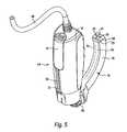
- FIG. 5is an isometric right side and rear view of the laryngoscope with the arm 14 in the closed position without the sheath 10 attached in accordance with a preferred embodiment.
- FIG. 6is an isometric right side, top view of the sheath 10 , in accordance with a preferred embodiment.
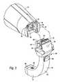
- FIG. 7is a top, front, and left side isometric view of the display unit with the stand in the open position.
- FIG. 8is rear elevation view of the display unit with the stand in the open position.
- FIG. 9is a right side isometric view of the display unit with the stand in the open position.
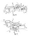
- FIG. 10is a rear isometric view of the IV pole attachment.
- FIG. 11is a front view of the IV pole attachment.
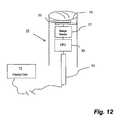
- FIG. 12is a block diagram depicting the camera 16 unit.
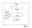
- FIG. 13is a block diagram depicting the laryngoscope motion sensor system.
- FIG. 14is a block diagram depicting the display unit motion sensor system.
- FIG. 15is a block diagram depicting the laryngoscope and display unit wireless communication system.
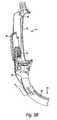
- FIG. 16is a side view of the laryngoscope and sheath, the bougie having been positioned within the trachea and an endotracheal tube threaded over the bougie, in accordance with a preferred embodiment of the method of the current invention (not to scale).
- This laryngoscope system 12is generally comprised of a laryngoscope 14 , a display unit 72 , and an IV pole attachment 98 capable of being coupled to an IV pole 128 .
- the laryngoscope 14 of the present inventioncomprises a handle 16 , a curved blade or arm 14 18 , a light 20 , a camera 16 22 , and a disposable sheath 10 24 .
- the handle 16 of the laryngoscope 14has a curved arm 14 18 attached.
- the arm 14 18is removably coupled to the handle 16 .
- Slideably coupled to the arm 14 18is a sheath 10 24 which snaps into place at a coupling point 68 ( FIG. 3 ).
- this sheath 10 24is formed from plastic and is at least partially clear so as to allow light emitted from the light 20 to pass through it. Referring to FIG.
- the sheath 10 24is comprised of a transparent window 28 .
- the sheath 10 24has one or more clasps 30 on its proximal end ( FIG. 6 ) which may be removably coupled to the arm 14 18 at the coupling point 68 ( FIG. 3 ).
- a userusing the thumb ejector 20 switch 34 , may eject the sheath 10 24 without physically touching the sheath 10 24 .
- the thumb ejector 20 switch 34is located at the upper end of the handle 16 .
- the thumb ejector 20 switch 34is comprised of a plunger block 36 , an ejection rod 38 , and a protrusion 40 .
- the thumb ejector 20 switch 34is coupled to the ejection rod 38 which is coupled at the top end with the plunger block 36 .
- the plunger block 36is comprised of the protrusion 40 .
- a return spring 42is coupled to the thumb ejector 20 switch 34 . This return spring 42 maintains the ejection rod 38 in a retracted position as a rest state ( FIG. 2A ).
- Above the plunger block 36is a retaining receptacle 44 .
- This retaining receptacle 44is structured and arranged such that it is capable of nesting the protrusion 40 and maintains the thumb ejector 20 switch 34 in a rest position and prevents accidental deployment of the ejection rod 38 .
- the sheath 10 24may be remotely ejected by depressing the thumb ejector 20 switch 34 ( FIG. 2B ) on the handle 16 which releases the clasp 30 at a sheath 10 connection ridge 58 located on the arm 14 18 at the coupling point 68 .
- the thumb injector switch 34when depressed, travels down a switch channel 31 ( FIG. 5 ).
- thumb ejector 20 switch 34further releases a spring element 60 ( FIG. 3 ) held in compression which, upon release, forcibly moves the sheath 10 24 along the length of the arm 14 , such that the sheath 10 becomes detached from the arm 14 .
- the clasp 30has a score line 32 or thinner layer of material. This score line 32 creates a weakened area in the clasp 30 so that when depressed by the ejection rod 38 , the clasp 30 is deformed at the score line 32 .
- the clasp 30after ejection, cannot be returned to its original un-deformed configuration without breaking at the score line 32 . Such breaking prevents the sheath 10 from being reused and thus, helps prevent contamination.
- the sheath 10is further comprised of a small canal 12 running at least partially along the outside length that serves as a guide for a bougie 70 .
- the practitionermay thread the bougie 70 through the sheath's bougie canal 12 into the airway and use this bougie 70 as a guide for an ET tube (not shown).
- this canal 12is open on one side 27 such that the bougie 70 may be inserted and removed through this open side 27 .
- This open side 27permits the user to maintain the laryngoscope 14 in the airway while threading the ET tube over the bougie 70 .
- the bougie 70is forced out of the canal 12 through the side opening 27 by the ET tube.
- this canal 12 with its open side 27is “C” shaped.
- This “C” shapehelps maintain the bougie 70 within the canal 12 while still allowing the bougie 70 to be removed through the open side 27 .
- the canal 12 of the preferred embodimentis open and forms a “C” shape, the canal 12 need not be open and need not be “C” shaped. Rather, the canal 12 can be closed on the sides so as to completely surround the bougie 70 along its length and can be circular or any other suitable shape.
- the laryngoscope 14also has a light 20 and a camera 16 positioned at the distal end of arm 14 and confined within arm 14 walls 10 beneath a transparent cap 66 .
- This cap 66is clear and allows light to reach the lens 56 and light generated from the light 20 to exit the arm 14 .
- a lens 56 for this camera 16is located in the arm 14 18 and the signal is transmitted through a cord 96 to a display unit 72 .
- the camera 16is solid state and does not rely upon mirrors or prisms, the camera 16 may be comprised of a lens 56 that focuses light as an image on a prism. The image may then reflected by the prism to the camera 16 22 .
- the lens 56 of the camera 16is also located at the distal end of the arm 14 .
- the main portion of the camera 16is located in the handle 16 and communicates with the lens 56 through a fiber optic cable.
- the camera 16transmits the signal directly to the display unit 72 without the use of mirrors and prisms.
- the camera 16is a complementary metal-oxide-semiconductor (CMOS) camera 16 .
- CMOScomplementary metal-oxide-semiconductor
- other cameras 22may be used including those incorporating charge-coupled device (CCD) technology.
- the camera 16transmits video images to the display unit 72 .
- the camera 16is comprised of a lens 56 , a shutter 51 , an image sensor 57 , a processor or CPU 59 , and a flex circuit 61 . Images collected by the camera 16 are displayed on the screen 88 of the display unit 72 .
- the camera 16 of the preferred embodimentproduces video images, it can also generate still images which may also be displayed on the screen 88 of the display unit 72 .
- the arm 14is comprised of a heating unit 21 .
- This heating unit 21heats the light 20 and camera 16 area and prevents the light 20 and camera 16 from developing moisture which may obscure the images gathered by the camera 16 .
- the heating unit 21is comprised of a thermistor 23 which monitors the temperature of the heating unit 21 and shuts the unit 21 off when a predetermined temperature is reached. In the preferred embodiment, such temperature is approximately 120 degrees Fahrenheit.
- the arm 14is further comprised of a flex circuit 61 ( FIG. 5 ). This circuit 61 is capable of supplying power to the camera 16 light 20 and heating unit 21 as well as transmitting information (including images) between the camera 16 and display unit 72 .
- the handle 16 and arm 14are each further comprised of heater switch 53 and 55 .
- the heater switch 53 and 55When the laryngoscope 14 is in the folded position, the heater switch 53 and 55 is in the open position and no power to the heater unit 21 is transferred. In this folded position, connectors 52 are also open such that power is not transferred to the light 20 , camera 16 , and heating unit 21 .
- a sheath 10 switch 25is located on the arm 14 .
- the sheath 10When the sheath 10 is in place and the arm 14 is in the working/engaged position as shown in FIGS. 2A and 2B , power is supplied to the heating unit 21 .
- the sheath 10 24is not present, as shown in FIG. 3 , or the arm 14 is in the folded/disengaged position depicted in FIG. 4 , the heater switch 53 , 55 is open, and no power is supplied to the heater unit 21 .
- the sheath 10 switch 25interrupts power to the handle portion 53 of heater switch 53 , 55 .
- the cord 96further transmits power from a power source to the light 20 camera 16 and heating unit 21 .
- the laryngoscope 14is comprised of a motion sensor 134 and processor 136 that allow the laryngoscope 14 to be motion activated such that the laryngoscope 14 is powered on upon a predetermined threshold of movement.
- the laryngoscope 14is capable of being motion activated such that the laryngoscope 14 is powered off when no movement is detected for a predetermined period of time.
- FIG. 3there is shown the connection assembly between the handle 16 and arm 14 .
- the arm 14is comprised of ball springs 62 .
- the ball springs 62slide into ball spring receptacles 48 .
- This connectionaligns arm 14 plate 64 with handle plate 50 within the walls 54 of handle plate 50 such that an electrical connection is made with connectors 52 .
- the display unit 72is comprised of a thin container 74 , a screen 88 , a DC Jack 94 , a battery management board and a battery.
- the container 74is comprised of an IV pole attachment connector 90 such that it may be removably coupled to an IV pole attachment receiver 100 ( FIG. 11 ) or, as shown in FIGS. 7 & 9 , sit upright on a stand 92 when not attached to the IV pole attachment receiver 100 .
- the container 74 of the preferred embodimentis generally rectangular and is comprised of a face 76 , a back 78 , and sides 80 .
- the stand 92is pivotally coupled to the back 78 and is structured and arranged such that it extends generally rearward from the back 78 when in use and folds flat against the back 78 in a recess 86 when in the stored position.
- said recess 86is contoured to the shape of the stand 92 .
- the display unit 72is comprised of a motion sensor 138 and processor 140 that allow the screen 88 to be motion activated such that the screen 88 is powered on upon a predetermined threshold movement.
- the screen 88is capable of being motion activated such that the screen 88 is powered off when no movement is detected for a predetermined period of time.
- the face 76has a battery status indicator 84 .
- This indicator 84is comprised of a plurality of LED 18 lights. In the preferred embodiment, two green lights showing indicate to the user that the battery is fully charged and the system 12 is operable. An amber light indicates the battery is depleted and will need to be charged soon. A red light indicates the battery lacks sufficient charge to operate the screen 88 , camera 16 , and light 20 .
- the indicator 84is positioned at the lower portion of the face 76 near the center and beneath the screen 88 .
- the back 78on the inside, has pegs and receptacles which act as coupling devices.
- the central pegs of the backcorrespond with receptacles located on the reverse side of the screen 88 .
- the perimeter receptaclescorrespond with pegs located on the inside side of the face 76 .
- the screen 88 and batteryare mounted on the inside portion of the back 78 of the container 74 .
- the battery of the preferred embodimentis a rechargeable lithium battery and is capable of illuminating the screen 88 .
- the screen 88 of the preferred embodimentis a 3:5 inch (Diagonal) Liquid Crystal Display (LCD).
- the screen 88displays the image captured by the camera 16 .
- the screen 88also displays other information such as the battery charge level, time, date, and the like.
- the display unit 72is further comprised of a DC input jack 94 and charge indicator 130 .
- This jack 94accepts the barrel portion of a charging cable.
- This jack 94connects with and is used to recharge the battery.
- the charge indicator 130is an LED 18 light that, when lit, alerts the user that the battery is being charged. In one aspect of the present invention, the unit 72 may not be operated while the charge cable is inserted into the jack 94
- the cable 62is capable of communicating images received from the camera 16 to the screen 88 through the communication jack 132 .
- the laryngoscope 14is capable of wirelessly communicating with the display unit 72 .
- the laryngoscope 14is further comprised of a transmitter 148 , a processor or CPU 152 and an antenna 150 .
- the display unit 72is further comprised of a receiver 142 , a processor or CPU 146 and an antenna 144 . Images captured by the camera 16 are processed by the CPU 152 and transmitted wirelessly to the display unit 72 receiver 142 such that the images are displayed on screen 88 .
- the communication cable 96is also capable of transmitting power generated by the battery to the light 20 and camera 16 .
- the battery management boardis a conventional and commercially available circuit board and is capable of maintaining an appropriate charge level in the battery.
- the IV pole 128is conventional and commercially available.
- the IV pole attachment 98is comprised of an attachment receiver 100 , an IV pole clamp 108 with a C shaped opening, a tightening screw 110 with wing knob 112 , and a laryngoscope receptacle 114 .
- the attachment receiver 100allows the user to quickly attach and separate the display unit 72 from IV pole attachment 98 and is comprised of a bracket 102 , and a quick release button 104 .
- the attachment connector 90 of the display unit 72may be slideably attached to the attachment receiver 100 .
- the usermay detach the display unit 72 from the attachment receiver 100 by depressing the release button 104 which activates a lever 106 that disengages the display unit 72 from the attachment receiver 100 .
- the IV pole attachment 98may be secured to an IV pole 128 by inserting the pole 128 in the IV clamp's 108 C shape opening and tightening the tightening screw 110 with the wing knob 112 .
- the laryngoscope receptacle 114is comprised of a contoured holder 116 and an extension portion 118 .
- the extension portion 118is comprised of a first member 124 and a second member 126 .
- the first member 124is structured and arranged such that it can rotate 360 degrees around an imaginary axis 120 that extends from a longitudinal axis of the extension portion 118 .
- the second member 126is structured and arranged such that it can rotate up to 360 degrees around an axis 122 perpendicular to the axis 120 around which the first member 124 rotates. Therefore, as may be seen in FIGS.
- the receptacle 114without the need for the user detaching the IV pole attachment 98 from the IV pole 128 , can be positioned on either side of an IV pole 128 and oriented such that the contoured holder 116 remains in an upright position and capable of receiving the laryngoscope 14 .
- the contoured holder 116is shaped to accommodate the laryngoscope 14 in the folded position as shown in FIG. 4 .
- the arm 14is made from stainless steel.
- the handle 16 and container 74are made from Acrylonitrile butadiene styrene (ABS). Although the handle 16 and container 74 of the preferred embodiment are formed from ABS, they need not be. For instance, the handle 16 and container 74 may be formed of any conventional material such as metal or plastic.
Landscapes
- Health & Medical Sciences (AREA)
- Life Sciences & Earth Sciences (AREA)
- Surgery (AREA)
- Radiology & Medical Imaging (AREA)
- Engineering & Computer Science (AREA)
- Veterinary Medicine (AREA)
- Biophysics (AREA)
- Nuclear Medicine, Radiotherapy & Molecular Imaging (AREA)
- Optics & Photonics (AREA)
- Pathology (AREA)
- Public Health (AREA)
- General Health & Medical Sciences (AREA)
- Physics & Mathematics (AREA)
- Biomedical Technology (AREA)
- Heart & Thoracic Surgery (AREA)
- Medical Informatics (AREA)
- Molecular Biology (AREA)
- Animal Behavior & Ethology (AREA)
- Otolaryngology (AREA)
- Physiology (AREA)
- Pulmonology (AREA)
- Endoscopes (AREA)
Abstract
Description
Claims (11)
Priority Applications (1)
| Application Number | Priority Date | Filing Date | Title |
|---|---|---|---|
| US13/373,880US8663099B2 (en) | 2009-03-31 | 2011-12-05 | System and method of insertion into an oropharyngeal area |
Applications Claiming Priority (4)
| Application Number | Priority Date | Filing Date | Title |
|---|---|---|---|
| US16509109P | 2009-03-31 | 2009-03-31 | |
| US12/750,784US8864657B2 (en) | 2009-03-31 | 2010-03-31 | Laryngoscope and system |
| US42260010P | 2010-12-13 | 2010-12-13 | |
| US13/373,880US8663099B2 (en) | 2009-03-31 | 2011-12-05 | System and method of insertion into an oropharyngeal area |
Related Parent Applications (2)
| Application Number | Title | Priority Date | Filing Date |
|---|---|---|---|
| US12/750,784ContinuationUS8864657B2 (en) | 2009-03-31 | 2010-03-31 | Laryngoscope and system |
| US12/750,784DivisionUS8864657B2 (en) | 2009-03-31 | 2010-03-31 | Laryngoscope and system |
Publications (2)
| Publication Number | Publication Date |
|---|---|
| US20120178997A1 US20120178997A1 (en) | 2012-07-12 |
| US8663099B2true US8663099B2 (en) | 2014-03-04 |
Family
ID=42785074
Family Applications (4)
| Application Number | Title | Priority Date | Filing Date |
|---|---|---|---|
| US12/750,784Active2030-08-30US8864657B2 (en) | 2009-03-31 | 2010-03-31 | Laryngoscope and system |
| US13/373,869AbandonedUS20120178996A1 (en) | 2009-03-31 | 2011-12-05 | System and method for viewing oropharyngeal area |
| US13/373,880Active2030-04-13US8663099B2 (en) | 2009-03-31 | 2011-12-05 | System and method of insertion into an oropharyngeal area |
| US13/374,985Expired - Fee RelatedUS9351633B2 (en) | 2009-03-31 | 2012-01-27 | Wireless control of laryngoscope system |
Family Applications Before (2)
| Application Number | Title | Priority Date | Filing Date |
|---|---|---|---|
| US12/750,784Active2030-08-30US8864657B2 (en) | 2009-03-31 | 2010-03-31 | Laryngoscope and system |
| US13/373,869AbandonedUS20120178996A1 (en) | 2009-03-31 | 2011-12-05 | System and method for viewing oropharyngeal area |
Family Applications After (1)
| Application Number | Title | Priority Date | Filing Date |
|---|---|---|---|
| US13/374,985Expired - Fee RelatedUS9351633B2 (en) | 2009-03-31 | 2012-01-27 | Wireless control of laryngoscope system |
Country Status (14)
| Country | Link |
|---|---|
| US (4) | US8864657B2 (en) |
| EP (1) | EP2414015B1 (en) |
| CA (1) | CA2756698C (en) |
| DK (1) | DK2414015T3 (en) |
| ES (1) | ES2899623T3 (en) |
| HR (1) | HRP20211849T1 (en) |
| HU (1) | HUE056824T2 (en) |
| LT (1) | LT2414015T (en) |
| MX (1) | MX2011010133A (en) |
| PL (1) | PL2414015T4 (en) |
| PT (1) | PT2414015T (en) |
| SI (1) | SI2414015T1 (en) |
| SM (1) | SMT202200018T1 (en) |
| WO (1) | WO2010114867A1 (en) |
Cited By (15)
| Publication number | Priority date | Publication date | Assignee | Title |
|---|---|---|---|---|
| US20120029293A1 (en)* | 2010-07-30 | 2012-02-02 | Vasan Nilesh R | Disposable, Self-Contained Laryngoscope and Method of Using Same |
| US20140257039A1 (en)* | 2013-03-08 | 2014-09-11 | Joel Feldman | Surgical retractor with smoke evacuator |
| US20150090845A1 (en)* | 2013-09-30 | 2015-04-02 | Covidien Lp | Medical Device Supporting Apparatus |
| US20150090849A1 (en)* | 2013-09-30 | 2015-04-02 | Covidien Lp | Medical device supporting apparatus |
| US9289114B2 (en)* | 2010-07-30 | 2016-03-22 | Nilesh R. Vasan | Disposable, self-contained laryngoscope and method of using same |
| USD788911S1 (en)* | 2013-03-14 | 2017-06-06 | Smith & Nephew, Inc. | Attachment for securing a therapy device |
| USD876625S1 (en) | 2018-08-07 | 2020-02-25 | Adroit Surgical, Llc | Laryngoscope |
| WO2021007085A1 (en)* | 2019-07-11 | 2021-01-14 | Imeson Shale | Curved bougie guide |
| US11051682B2 (en) | 2017-08-31 | 2021-07-06 | Wm & Dg, Inc. | Medical devices with camera and methods of placement |
| US11147442B2 (en)* | 2014-08-08 | 2021-10-19 | Wm & Dg, Inc. | Medical devices and methods of placement |
| US20210353888A1 (en)* | 2020-05-12 | 2021-11-18 | Samuel Wilson | Endotracheal Tube with Fulcrum |
| US11202561B2 (en) | 2014-08-08 | 2021-12-21 | Wm & Dg, Inc. | Medical devices and methods of placement |
| US11517694B1 (en) | 2018-06-05 | 2022-12-06 | Jeremy Joseph Beaver | Yankauer suction device with auxiliary access port |
| USD1055275S1 (en) | 2020-05-12 | 2024-12-24 | Samuel Wilson | Endotracheal tube |
| US12303632B1 (en) | 2018-06-05 | 2025-05-20 | Vernon Bradley Taylor | Airway management device |
Families Citing this family (116)
| Publication number | Priority date | Publication date | Assignee | Title |
|---|---|---|---|---|
| US10299668B2 (en)* | 2005-10-21 | 2019-05-28 | Physio-Control, Inc. | Laryngoscope with handle-grip activated recording |
| USD618794S1 (en)* | 2005-10-25 | 2010-06-29 | Pentax Corporation | Video laryngoscope |
| US9095298B2 (en)* | 2008-06-23 | 2015-08-04 | Intubrite, Llc | Adjustable display mechanism and method |
| US8382665B1 (en)* | 2009-02-12 | 2013-02-26 | Alfred Fam | Endotracheal tube placement system and method |
| US9492063B2 (en) | 2009-06-18 | 2016-11-15 | Endochoice Innovation Center Ltd. | Multi-viewing element endoscope |
| US10524645B2 (en) | 2009-06-18 | 2020-01-07 | Endochoice, Inc. | Method and system for eliminating image motion blur in a multiple viewing elements endoscope |
| US10165929B2 (en) | 2009-06-18 | 2019-01-01 | Endochoice, Inc. | Compact multi-viewing element endoscope system |
| US11547275B2 (en) | 2009-06-18 | 2023-01-10 | Endochoice, Inc. | Compact multi-viewing element endoscope system |
| US9474440B2 (en) | 2009-06-18 | 2016-10-25 | Endochoice, Inc. | Endoscope tip position visual indicator and heat management system |
| US9706903B2 (en) | 2009-06-18 | 2017-07-18 | Endochoice, Inc. | Multiple viewing elements endoscope system with modular imaging units |
| US9872609B2 (en) | 2009-06-18 | 2018-01-23 | Endochoice Innovation Center Ltd. | Multi-camera endoscope |
| US12137873B2 (en) | 2009-06-18 | 2024-11-12 | Endochoice, Inc. | Compact multi-viewing element endoscope system |
| US9901244B2 (en) | 2009-06-18 | 2018-02-27 | Endochoice, Inc. | Circuit board assembly of a multiple viewing elements endoscope |
| US9713417B2 (en) | 2009-06-18 | 2017-07-25 | Endochoice, Inc. | Image capture assembly for use in a multi-viewing elements endoscope |
| US10130246B2 (en) | 2009-06-18 | 2018-11-20 | Endochoice, Inc. | Systems and methods for regulating temperature and illumination intensity at the distal tip of an endoscope |
| US11278190B2 (en) | 2009-06-18 | 2022-03-22 | Endochoice, Inc. | Multi-viewing element endoscope |
| WO2010146587A1 (en) | 2009-06-18 | 2010-12-23 | Peer Medical Ltd. | Multi-camera endoscope |
| WO2011038126A1 (en)* | 2009-09-25 | 2011-03-31 | Spectrum Health Innovations, LLC | Laryngoscope guide and related method of use |
| USD637717S1 (en)* | 2009-10-02 | 2011-05-10 | Indian Ocean Medical Inc. | Laryngoscope |
| US9179831B2 (en) | 2009-11-30 | 2015-11-10 | King Systems Corporation | Visualization instrument |
| US12220105B2 (en) | 2010-06-16 | 2025-02-11 | Endochoice, Inc. | Circuit board assembly of a multiple viewing elements endoscope |
| USD663026S1 (en)* | 2010-09-01 | 2012-07-03 | King Systems Corporation | Visualization instrument |
| US9560953B2 (en) | 2010-09-20 | 2017-02-07 | Endochoice, Inc. | Operational interface in a multi-viewing element endoscope |
| EP2618718B1 (en) | 2010-09-20 | 2020-04-15 | EndoChoice Innovation Center Ltd. | Multi-camera endoscope having fluid channels |
| TWD145549S (en)* | 2010-10-13 | 2012-02-21 | 航空醫學有限公司 | Video laryngoscope |
| USD659246S1 (en)* | 2010-10-13 | 2012-05-08 | Aircraft Medical Limited | Video laryngoscope blade |
| US9706908B2 (en) | 2010-10-28 | 2017-07-18 | Endochoice, Inc. | Image capture and video processing systems and methods for multiple viewing element endoscopes |
| US10663714B2 (en) | 2010-10-28 | 2020-05-26 | Endochoice, Inc. | Optical system for an endoscope |
| CN103403605A (en) | 2010-10-28 | 2013-11-20 | 恩多巧爱思创新中心有限公司 | Optical systems for multi-sensor endoscopes |
| US12204087B2 (en) | 2010-10-28 | 2025-01-21 | Endochoice, Inc. | Optical systems for multi-sensor endoscopes |
| US11889986B2 (en) | 2010-12-09 | 2024-02-06 | Endochoice, Inc. | Flexible electronic circuit board for a multi-camera endoscope |
| CN107361721B (en) | 2010-12-09 | 2019-06-18 | 恩多巧爱思创新中心有限公司 | Flexible electronic circuit boards for multi-camera endoscopes |
| WO2012097181A1 (en)* | 2011-01-12 | 2012-07-19 | King Systems Corporation | Visualization instrument |
| EP2672878B1 (en) | 2011-02-07 | 2017-11-22 | Endochoice Innovation Center Ltd. | Multi-element cover for a multi-camera endoscope |
| US10517464B2 (en) | 2011-02-07 | 2019-12-31 | Endochoice, Inc. | Multi-element cover for a multi-camera endoscope |
| US9216323B2 (en)* | 2011-03-25 | 2015-12-22 | Eric Davis Schwartz | Retrieving device |
| ES2396791B1 (en)* | 2011-03-28 | 2013-11-11 | Prodol Meditec, S.A. | OPTICAL LIGHTING LINGING SCOPE. |
| USD660425S1 (en)* | 2011-06-14 | 2012-05-22 | Bigelow Warren V | Bracket for securing laryngoscope components |
| US9300052B2 (en)* | 2011-12-09 | 2016-03-29 | Robert F. Schweppe | Adjustable antenna system |
| CA2798716A1 (en) | 2011-12-13 | 2013-06-13 | Peermedical Ltd. | Removable tip endoscope |
| US20130225929A1 (en)* | 2012-02-23 | 2013-08-29 | Murray Alsip | Quick attach laryngoscope power generator device |
| EP2848276B1 (en)* | 2012-05-08 | 2020-03-18 | Prodol Meditec S.A. | Optical device, sheath and endotracheal intubation system |
| EP2868096B1 (en) | 2012-06-27 | 2020-08-05 | Zipline Health, Inc. | Devices, methods and systems for acquiring medical diagnostic information and provision of telehealth services |
| US9560954B2 (en) | 2012-07-24 | 2017-02-07 | Endochoice, Inc. | Connector for use with endoscope |
| US9107628B2 (en)* | 2012-10-12 | 2015-08-18 | Karl Storz Gmbh & Co. Kg | Video laryngoscope with disposable blade |
| US20140200402A1 (en) | 2013-01-16 | 2014-07-17 | Phillip Jack Snoke | Medical Device Introduction Systems and Methods |
| US20170055813A1 (en) | 2013-01-16 | 2017-03-02 | Uvision 360, Inc. | Medical device introduction and imaging system, and associated method |
| US9662466B2 (en)* | 2013-03-15 | 2017-05-30 | Sanovas, Inc. | Imaging stylet for intubation |
| US9986899B2 (en) | 2013-03-28 | 2018-06-05 | Endochoice, Inc. | Manifold for a multiple viewing elements endoscope |
| US9993142B2 (en) | 2013-03-28 | 2018-06-12 | Endochoice, Inc. | Fluid distribution device for a multiple viewing elements endoscope |
| US9636003B2 (en) | 2013-06-28 | 2017-05-02 | Endochoice, Inc. | Multi-jet distributor for an endoscope |
| US10595714B2 (en) | 2013-03-28 | 2020-03-24 | Endochoice, Inc. | Multi-jet controller for an endoscope |
| US12207796B2 (en) | 2013-03-28 | 2025-01-28 | Endochoice Inc. | Multi-jet controller for an endoscope |
| DE102013207662A1 (en)* | 2013-04-26 | 2014-10-30 | Vbm Medizintechnik Gmbh | Insertion aid for a breathing tube |
| WO2014182723A1 (en) | 2013-05-07 | 2014-11-13 | Endochoice, Inc. | White balance enclosed for use with a multi-viewing elements endoscope |
| US10499794B2 (en) | 2013-05-09 | 2019-12-10 | Endochoice, Inc. | Operational interface in a multi-viewing element endoscope |
| US9949623B2 (en) | 2013-05-17 | 2018-04-24 | Endochoice, Inc. | Endoscope control unit with braking system |
| USD724208S1 (en)* | 2013-06-25 | 2015-03-10 | Intersurgical Ag | Laryngoscope |
| US10064541B2 (en) | 2013-08-12 | 2018-09-04 | Endochoice, Inc. | Endoscope connector cover detection and warning system |
| US9521303B2 (en)* | 2013-08-26 | 2016-12-13 | SeeScan, Inc. | Cable storage drum with moveable CCU docking apparatus |
| US9943218B2 (en) | 2013-10-01 | 2018-04-17 | Endochoice, Inc. | Endoscope having a supply cable attached thereto |
| US20150112146A1 (en)* | 2013-10-21 | 2015-04-23 | Jill Donaldson | Video Laryngoscope with Adjustable Handle Mounted Monitor |
| US9968242B2 (en) | 2013-12-18 | 2018-05-15 | Endochoice, Inc. | Suction control unit for an endoscope having two working channels |
| WO2015112747A2 (en) | 2014-01-22 | 2015-07-30 | Endochoice, Inc. | Image capture and video processing systems and methods for multiple viewing element endoscopes |
| CN103784109A (en)* | 2014-01-29 | 2014-05-14 | 乌日娜 | Split type hook video laryngoscope |
| CN103784108A (en)* | 2014-01-29 | 2014-05-14 | 丁永乐 | Split type horizontal inserting video laryngoscope |
| US11234581B2 (en) | 2014-05-02 | 2022-02-01 | Endochoice, Inc. | Elevator for directing medical tool |
| EP3689219B1 (en) | 2014-07-21 | 2023-08-30 | EndoChoice, Inc. | Multi-focal, multi-camera endoscope systems |
| CN204049606U (en)* | 2014-07-22 | 2014-12-31 | 芯发威达电子(上海)有限公司 | Automatically the laryngopharyngeal mirror of image frame can be adjusted |
| US10542877B2 (en) | 2014-08-29 | 2020-01-28 | Endochoice, Inc. | Systems and methods for varying stiffness of an endoscopic insertion tube |
| HK1245056A1 (en) | 2014-12-12 | 2018-08-24 | Airway Medical Innovations Pty Ltd. | Intubation device |
| EP3235241B1 (en) | 2014-12-18 | 2023-09-06 | EndoChoice, Inc. | System for processing video images generated by a multiple viewing elements endoscope |
| WO2016112034A2 (en) | 2015-01-05 | 2016-07-14 | Endochoice, Inc. | Tubed manifold of a multiple viewing elements endoscope |
| US10376181B2 (en) | 2015-02-17 | 2019-08-13 | Endochoice, Inc. | System for detecting the location of an endoscopic device during a medical procedure |
| US9782061B2 (en) | 2015-03-04 | 2017-10-10 | Velosal Medical, Inc. | Video laryngoscopy device |
| US10238790B2 (en)* | 2015-03-06 | 2019-03-26 | Carefusion 2200, Inc. | Syringe holder |
| US10078207B2 (en) | 2015-03-18 | 2018-09-18 | Endochoice, Inc. | Systems and methods for image magnification using relative movement between an image sensor and a lens assembly |
| US10401611B2 (en) | 2015-04-27 | 2019-09-03 | Endochoice, Inc. | Endoscope with integrated measurement of distance to objects of interest |
| US10516865B2 (en) | 2015-05-17 | 2019-12-24 | Endochoice, Inc. | Endoscopic image enhancement using contrast limited adaptive histogram equalization (CLAHE) implemented in a processor |
| GB2538552B (en) | 2015-05-21 | 2020-03-11 | Intersurgical Ag | Video laryngoscopes |
| CA2988923A1 (en)* | 2015-06-08 | 2016-12-15 | The General Hospital Corporation | Airway management and visualization device |
| US20170119474A1 (en) | 2015-10-28 | 2017-05-04 | Endochoice, Inc. | Device and Method for Tracking the Position of an Endoscope within a Patient's Body |
| TWI572087B (en) | 2015-11-03 | 2017-02-21 | 啟碁科技股份有限公司 | Support assembly and satellite antenna module using the same |
| US10588502B2 (en) | 2015-11-18 | 2020-03-17 | Sanovas Intellectual Property, Llc | Side loading articulating laryngeal access system |
| EP4579310A3 (en) | 2015-11-24 | 2025-09-10 | Endochoice, Inc. | Disposable air/water and suction valves for an endoscope |
| US10272217B2 (en)* | 2015-12-08 | 2019-04-30 | Boyi Gao | Device for gripping and directing bougies for intubation |
| TWM519485U (en)* | 2016-01-14 | 2016-04-01 | Dex Medical Device Co Ltd | Improved structure of miniature observation lens camera lens (1) |
| US11166628B2 (en) | 2016-02-02 | 2021-11-09 | Physio-Control, Inc. | Laryngoscope with handle-grip activated recording |
| JP2019507628A (en) | 2016-02-24 | 2019-03-22 | エンドチョイス インコーポレイテッドEndochoice, Inc. | Circuit board assembly for multiple view element endoscopes using CMOS sensors |
| US10292570B2 (en) | 2016-03-14 | 2019-05-21 | Endochoice, Inc. | System and method for guiding and tracking a region of interest using an endoscope |
| EP3429478B1 (en) | 2016-06-21 | 2021-04-21 | Endochoice, Inc. | Endoscope system with multiple connection interfaces to interface with different video data signal sources |
| ES1163460Y (en) | 2016-07-28 | 2016-11-17 | Aimplas Asoc De Investig De Mat Plasticos Y Conexas | CONVERSOR DEVICE FOR LONGING SCOPE |
| USD862199S1 (en)* | 2016-08-31 | 2019-10-08 | Avent, Inc. | Mounting bracket |
| TW201818868A (en)* | 2016-11-16 | 2018-06-01 | 陳天生 | Laryngoscope |
| CN110139594A (en)* | 2017-01-03 | 2019-08-16 | N·P·内文 | Video laryngoscope accessories for mobile communication devices |
| USD846119S1 (en) | 2017-01-24 | 2019-04-16 | Medtronic Advanced Energy Llc | Lighted surgical retractor base |
| WO2018140208A1 (en) | 2017-01-24 | 2018-08-02 | Medtronic Advanced Energy Llc | Modular lighted surgical retractor |
| US10729317B2 (en)* | 2017-05-26 | 2020-08-04 | Karl Storz Se & Co. Kg | Intubation instrument |
| EP3664686A4 (en)* | 2017-08-07 | 2021-04-21 | Weinmann, Maxwell | LARYNGOSCOPE |
| US10278572B1 (en) | 2017-10-19 | 2019-05-07 | Obp Medical Corporation | Speculum |
| US11033180B2 (en)* | 2017-11-03 | 2021-06-15 | Aircraft Medical Ltd. | Video laryngoscope systems and methods |
| US10758214B2 (en) | 2017-11-13 | 2020-09-01 | UVision360, Inc. | Biopsy device and method |
| CN107928615A (en)* | 2017-12-06 | 2018-04-20 | 广东名威科技有限公司 | a visual laryngoscope |
| CN109965835A (en)* | 2017-12-28 | 2019-07-05 | 太平洋医疗耗材实业有限公司 | Laryngoscope system and blade assembly |
| DE102018105538A1 (en) | 2018-03-09 | 2019-09-12 | Karl Storz Se & Co. Kg | Laryngoscope and spatula for a laryngoscope |
| CN109091100B (en)* | 2018-06-20 | 2021-02-12 | 连云港市第一人民医院 | Portable otolaryngology snooping mirror |
| EP3990073A4 (en) | 2018-06-25 | 2023-07-05 | Airway Medical Innovations Pty Ltd. | AIRWAY MANIPULATION DEVICES |
| USD912802S1 (en)* | 2018-10-30 | 2021-03-09 | Water Pik, Inc. | Oral irrigator handle |
| US10863886B2 (en) | 2019-05-03 | 2020-12-15 | UVision360, Inc. | Rotatable introducers |
| CN114423332A (en)* | 2019-06-24 | 2022-04-29 | 气道医疗创新责任有限公司 | Shielded cannula guide and method |
| EP4110256A4 (en)* | 2020-02-28 | 2024-03-27 | Technologies CGC Inc. | Coupling systems for releasably coupling equipment to a patient transport system |
| US20210299378A1 (en)* | 2020-03-31 | 2021-09-30 | Air Boost, LLC | Emergency ventilator |
| US11724053B2 (en) | 2020-04-01 | 2023-08-15 | Boyi Gao | Device for gripping and securing an intubation bougie |
| CA3117116A1 (en)* | 2020-04-13 | 2021-10-13 | AIMIC Corp. | An imaging system and method for quality and dosage control of anesthetics applied by a spray nozzle |
| FR3114955A1 (en)* | 2020-10-12 | 2022-04-15 | Vital Technics | LARYNGOSCOPE BLADE OR LARYNGOSCOPE INTEGRATING THIS BLADE WITH SPECIFIC SHAPES FOR GUIDED ENDOTRACHEAL TUBE AND ASSOCIATED METHOD |
| AR119254A1 (en)* | 2020-10-30 | 2021-12-09 | Guillermo Leonardo Siebenhaar | VIDEOLARYNGOSCOPE FOR THE MANAGEMENT OF AN AIRWAY OF AN INDIVIDUAL WHO NEEDS IT |
Citations (44)
| Publication number | Priority date | Publication date | Assignee | Title |
|---|---|---|---|---|
| US2646036A (en) | 1950-03-24 | 1953-07-21 | Welch Allyn Inc | Foldable and separable laryngoscope |
| US4185639A (en) | 1978-03-27 | 1980-01-29 | Linder Gerald S | Adjustable stop for endotracheal tube guide |
| US4832020A (en)* | 1987-03-24 | 1989-05-23 | Augustine Scott D | Tracheal intubation guide |
| US4834077A (en) | 1985-03-19 | 1989-05-30 | Sun William Y | Sterile disposable linguiform laryngoscope blade sheath |
| US4979499A (en) | 1985-03-19 | 1990-12-25 | Sun William Y | Sterile disposable linguiform laryngoscope blade sheath |
| US5487607A (en) | 1992-04-08 | 1996-01-30 | Omron Corporation | Radiation clinical thermometer |
| US5645519A (en)* | 1994-03-18 | 1997-07-08 | Jai S. Lee | Endoscopic instrument for controlled introduction of tubular members in the body and methods therefor |
| US5743849A (en) | 1996-08-09 | 1998-04-28 | Blue Ridge Products, Lp | Disposable protective sleeve for a laryngoscope and method of using the same |
| US5766202A (en) | 1997-01-21 | 1998-06-16 | Pilling Weck Incorporated | Wire-guided esophagael bougie |
| US5800344A (en) | 1996-10-23 | 1998-09-01 | Welch Allyn, Inc. | Video laryngoscope |
| US5810770A (en) | 1996-12-13 | 1998-09-22 | Stryker Corporation | Fluid management pump system for surgical procedures |
| US5846186A (en) | 1996-09-24 | 1998-12-08 | Mercury Enterprises, Inc. | Endoscope system and coupling arrangement for use therewith |
| WO1998055170A1 (en) | 1997-06-03 | 1998-12-10 | Board Of Regents The University Of Texas System | Endotracheal tube guide and related tracheostomy surgical procedure |
| US6142144A (en) | 1997-12-01 | 2000-11-07 | Pacey; John A. | Intubation instrument |
| US6146402A (en) | 1997-06-09 | 2000-11-14 | Munoz; Cayetano S. | Endotracheal tube guide introducer and method of intubation |
| US6248061B1 (en) | 1999-11-04 | 2001-06-19 | Lewis L. Cook, Jr. | Suctioning laryngoscope blade |
| US20010014768A1 (en) | 1999-06-21 | 2001-08-16 | Kaplan Marshal B. | Rigid intubating laryngoscope with interchangeable blade and video display |
| US20020082478A1 (en) | 2000-12-23 | 2002-06-27 | Mcgrath Matthew J.R. | Laryngoscope |
| US6494826B1 (en) | 1997-04-14 | 2002-12-17 | Karl Storz Gmbh & Co. Kg | Coupling for a mechanical a light-guiding and an image-guiding connection of an endoscope to a camera module |
| US6543447B2 (en) | 1997-12-01 | 2003-04-08 | Saturn Biomedical Systems Inc | Intubation instrument |
| US6569089B1 (en) | 1999-12-03 | 2003-05-27 | Roy Covington | Lighted intubating laryngoscope |
| US6655377B2 (en) | 1997-12-01 | 2003-12-02 | Saturn Biomedical Systems Inc. | Intubation instrument |
| US6666819B2 (en) | 2000-12-06 | 2003-12-23 | Heine Optotechnik Gmbh & Co. Kg | Laryngoscope |
| WO2004096031A1 (en) | 2003-04-29 | 2004-11-11 | Aircraft Medical Limited | Laryngoscope with means to restrict re-use of blades |
| US6817973B2 (en) | 2000-03-16 | 2004-11-16 | Immersion Medical, Inc. | Apparatus for controlling force for manipulation of medical instruments |
| US6840903B2 (en) | 2002-03-21 | 2005-01-11 | Nuvista Technology Corporation | Laryngoscope with image sensor |
| US6843769B1 (en) | 2000-04-18 | 2005-01-18 | Page 65, S.L. | Optical luminous laryngoscope |
| US6890298B2 (en) | 1999-10-14 | 2005-05-10 | Karl Storz Gmbh & Co. Kg | Video laryngoscope with detachable light and image guides |
| US20060020166A1 (en) | 2004-07-21 | 2006-01-26 | Jonathan Berall | Protection of sensitive instruments |
| US20060165152A1 (en) | 2003-01-06 | 2006-07-27 | Sherwood Services Ag | Tympanic thermomether probe cover with film support mechanism |
| US20060276694A1 (en)* | 2003-02-24 | 2006-12-07 | Pedro Acha Gandarias | Luminous optical laryngoscope comprising built-in fluid-extraction device |
| US20060276693A1 (en) | 2005-04-01 | 2006-12-07 | Pacey John A | Video rectractor |
| USD534652S1 (en) | 2004-11-30 | 2007-01-02 | Aircraft Medical Limited | Laryngoscope blade |
| US20070179342A1 (en) | 2006-01-12 | 2007-08-02 | Kb Port Llc | Wireless Laryngoscope with Internal Antennae and One Piece Construction Adapted for Laryngoscopy Training |
| US20070197873A1 (en) | 2006-02-21 | 2007-08-23 | Karl Storz Gmbh & Co. Kg | Wireless optical endoscopic device |
| US20080045801A1 (en) | 2006-08-15 | 2008-02-21 | M.S. Vision Ltd. | Intubation laryngoscope with detachable blades |
| US7347863B2 (en) | 2004-05-07 | 2008-03-25 | Usgi Medical, Inc. | Apparatus and methods for manipulating and securing tissue |
| US20080177146A1 (en) | 2007-01-19 | 2008-07-24 | Tien-Sheng Chen | Double Vision Endotracheal Tube Installation System |
| US20080177147A1 (en) | 2007-01-24 | 2008-07-24 | Jonathan Simons | Laryngoscope |
| US20080249370A1 (en) | 2007-04-04 | 2008-10-09 | Dashiell Birnkrant | Video blade laryngoscope |
| WO2008138119A1 (en) | 2007-05-14 | 2008-11-20 | University Of Manitoba | Bougie device |
| USD590501S1 (en) | 2004-11-30 | 2009-04-14 | Aircraft Medical Limited | Laryngoscope handle |
| US20090299146A1 (en) | 2005-12-09 | 2009-12-03 | Aircraft Medical Limited | Laryngoscope Blade |
| WO2010100497A1 (en) | 2009-03-03 | 2010-09-10 | Aircraft Medical Limited | Introducer guide |
Family Cites Families (16)
| Publication number | Priority date | Publication date | Assignee | Title |
|---|---|---|---|---|
| US4579108A (en) | 1983-03-07 | 1986-04-01 | Jack Bauman | Laryngoscope blade and disposable cover |
| WO1998055841A2 (en)* | 1997-06-03 | 1998-12-10 | Trutek Inc. | Tympanic thermometer with modular sensing probe |
| DE60039731D1 (en)* | 1999-02-10 | 2008-09-11 | Ilc Dover Inc | Method for the controlled transfer of particles |
| US6652453B2 (en)* | 1999-03-03 | 2003-11-25 | Vincent A. Smith | Portable video laryngoscope |
| US6929600B2 (en)* | 2001-07-24 | 2005-08-16 | Stephen D. Hill | Apparatus for intubation |
| US20030100819A1 (en)* | 2001-11-28 | 2003-05-29 | Welch Allyn, Inc. | Hand-held chemical sensing instrument |
| US20060004258A1 (en)* | 2004-07-02 | 2006-01-05 | Wei-Zen Sun | Image-type intubation-aiding device |
| US20060020176A1 (en)* | 2004-07-21 | 2006-01-26 | Jonathan Berall | Portable handheld medical diagnostic tool ''Camcorder handle'' |
| US7077909B1 (en)* | 2004-10-26 | 2006-07-18 | Crane Richie L | Doorknob paint shield |
| US20070195539A1 (en)* | 2006-02-21 | 2007-08-23 | Karl Storz Gmbh & Co. Kg | Ultra wide band wireless optical endoscopic device |
| US8398545B2 (en)* | 2007-01-19 | 2013-03-19 | Tien-Sheng Chen | Laryngoscope with a movable image-capturing unit |
| US9386914B2 (en)* | 2007-04-04 | 2016-07-12 | Karl Storz Endovision, Inc. | Video endoscopic device with detachable control circuit |
| US9095298B2 (en)* | 2008-06-23 | 2015-08-04 | Intubrite, Llc | Adjustable display mechanism and method |
| US20110245609A1 (en)* | 2010-03-30 | 2011-10-06 | Vadim Laser | Video adapter for laryngoscope |
| US8414481B2 (en)* | 2010-06-24 | 2013-04-09 | General Electric Company | Laryngoscope |
| US20120149980A1 (en)* | 2010-12-08 | 2012-06-14 | Verathon Medical (Canada) Ulc | Video cricothyrotomy camera and cannula system |
- 2010
- 2010-03-31HRHRP20211849TTpatent/HRP20211849T1/enunknown
- 2010-03-31MXMX2011010133Apatent/MX2011010133A/ennot_activeApplication Discontinuation
- 2010-03-31WOPCT/US2010/029303patent/WO2010114867A1/enactiveApplication Filing
- 2010-03-31LTLTEPPCT/US2010/029303Tpatent/LT2414015T/enunknown
- 2010-03-31SMSM20220018Tpatent/SMT202200018T1/enunknown
- 2010-03-31CACA2756698Apatent/CA2756698C/enactiveActive
- 2010-03-31DKDK10759321.2Tpatent/DK2414015T3/enactive
- 2010-03-31SISI201032098Tpatent/SI2414015T1/enunknown
- 2010-03-31EPEP10759321.2Apatent/EP2414015B1/enactiveActive
- 2010-03-31HUHUE10759321Apatent/HUE056824T2/enunknown
- 2010-03-31PLPL10759321Tpatent/PL2414015T4/enunknown
- 2010-03-31USUS12/750,784patent/US8864657B2/enactiveActive
- 2010-03-31ESES10759321Tpatent/ES2899623T3/enactiveActive
- 2010-03-31PTPT107593212Tpatent/PT2414015T/enunknown
- 2011
- 2011-12-05USUS13/373,869patent/US20120178996A1/ennot_activeAbandoned
- 2011-12-05USUS13/373,880patent/US8663099B2/enactiveActive
- 2012
- 2012-01-27USUS13/374,985patent/US9351633B2/ennot_activeExpired - Fee Related
Patent Citations (52)
| Publication number | Priority date | Publication date | Assignee | Title |
|---|---|---|---|---|
| US2646036A (en) | 1950-03-24 | 1953-07-21 | Welch Allyn Inc | Foldable and separable laryngoscope |
| US4185639A (en) | 1978-03-27 | 1980-01-29 | Linder Gerald S | Adjustable stop for endotracheal tube guide |
| US4834077A (en) | 1985-03-19 | 1989-05-30 | Sun William Y | Sterile disposable linguiform laryngoscope blade sheath |
| US4979499A (en) | 1985-03-19 | 1990-12-25 | Sun William Y | Sterile disposable linguiform laryngoscope blade sheath |
| US4832020A (en)* | 1987-03-24 | 1989-05-23 | Augustine Scott D | Tracheal intubation guide |
| US5487607A (en) | 1992-04-08 | 1996-01-30 | Omron Corporation | Radiation clinical thermometer |
| US5645519A (en)* | 1994-03-18 | 1997-07-08 | Jai S. Lee | Endoscopic instrument for controlled introduction of tubular members in the body and methods therefor |
| US5743849A (en) | 1996-08-09 | 1998-04-28 | Blue Ridge Products, Lp | Disposable protective sleeve for a laryngoscope and method of using the same |
| US5846186A (en) | 1996-09-24 | 1998-12-08 | Mercury Enterprises, Inc. | Endoscope system and coupling arrangement for use therewith |
| US5800344A (en) | 1996-10-23 | 1998-09-01 | Welch Allyn, Inc. | Video laryngoscope |
| US5810770A (en) | 1996-12-13 | 1998-09-22 | Stryker Corporation | Fluid management pump system for surgical procedures |
| US5766202A (en) | 1997-01-21 | 1998-06-16 | Pilling Weck Incorporated | Wire-guided esophagael bougie |
| US6494826B1 (en) | 1997-04-14 | 2002-12-17 | Karl Storz Gmbh & Co. Kg | Coupling for a mechanical a light-guiding and an image-guiding connection of an endoscope to a camera module |
| WO1998055170A1 (en) | 1997-06-03 | 1998-12-10 | Board Of Regents The University Of Texas System | Endotracheal tube guide and related tracheostomy surgical procedure |
| US6146402A (en) | 1997-06-09 | 2000-11-14 | Munoz; Cayetano S. | Endotracheal tube guide introducer and method of intubation |
| US6142144A (en) | 1997-12-01 | 2000-11-07 | Pacey; John A. | Intubation instrument |
| US6655377B2 (en) | 1997-12-01 | 2003-12-02 | Saturn Biomedical Systems Inc. | Intubation instrument |
| US6543447B2 (en) | 1997-12-01 | 2003-04-08 | Saturn Biomedical Systems Inc | Intubation instrument |
| US20010014768A1 (en) | 1999-06-21 | 2001-08-16 | Kaplan Marshal B. | Rigid intubating laryngoscope with interchangeable blade and video display |
| US6354993B1 (en) | 1999-06-21 | 2002-03-12 | Karl Storz Gmbh & Co. Kg | Rigid intubating laryngoscope with interchangeable blade and video display |
| US6890298B2 (en) | 1999-10-14 | 2005-05-10 | Karl Storz Gmbh & Co. Kg | Video laryngoscope with detachable light and image guides |
| US7044909B2 (en) | 1999-10-14 | 2006-05-16 | Karl Storz Gmbh & Co. Kg | Video laryngoscope with detachable light and image guides |
| US6248061B1 (en) | 1999-11-04 | 2001-06-19 | Lewis L. Cook, Jr. | Suctioning laryngoscope blade |
| US6569089B1 (en) | 1999-12-03 | 2003-05-27 | Roy Covington | Lighted intubating laryngoscope |
| US6817973B2 (en) | 2000-03-16 | 2004-11-16 | Immersion Medical, Inc. | Apparatus for controlling force for manipulation of medical instruments |
| US6843769B1 (en) | 2000-04-18 | 2005-01-18 | Page 65, S.L. | Optical luminous laryngoscope |
| US6666819B2 (en) | 2000-12-06 | 2003-12-23 | Heine Optotechnik Gmbh & Co. Kg | Laryngoscope |
| US20040127770A1 (en) | 2000-12-23 | 2004-07-01 | Mcgrath Matthew J.R. | Laryngoscope |
| WO2002051304A1 (en) | 2000-12-23 | 2002-07-04 | Mcgrath, Matthew, J.,R. | Laryngoscope |
| US20020082478A1 (en) | 2000-12-23 | 2002-06-27 | Mcgrath Matthew J.R. | Laryngoscope |
| US6840903B2 (en) | 2002-03-21 | 2005-01-11 | Nuvista Technology Corporation | Laryngoscope with image sensor |
| US20060165152A1 (en) | 2003-01-06 | 2006-07-27 | Sherwood Services Ag | Tympanic thermomether probe cover with film support mechanism |
| US20060276694A1 (en)* | 2003-02-24 | 2006-12-07 | Pedro Acha Gandarias | Luminous optical laryngoscope comprising built-in fluid-extraction device |
| WO2004096031A1 (en) | 2003-04-29 | 2004-11-11 | Aircraft Medical Limited | Laryngoscope with means to restrict re-use of blades |
| WO2004096032A1 (en) | 2003-04-29 | 2004-11-11 | Aircraft Medical Limited | Laryngoscope with camera attachment |
| US20070299313A1 (en) | 2003-04-29 | 2007-12-27 | Mcgrath Matthew J | Laryngoscope With Means to Restrict Re-Use of Blades |
| US7347863B2 (en) | 2004-05-07 | 2008-03-25 | Usgi Medical, Inc. | Apparatus and methods for manipulating and securing tissue |
| US20060020166A1 (en) | 2004-07-21 | 2006-01-26 | Jonathan Berall | Protection of sensitive instruments |
| USD590501S1 (en) | 2004-11-30 | 2009-04-14 | Aircraft Medical Limited | Laryngoscope handle |
| USD534652S1 (en) | 2004-11-30 | 2007-01-02 | Aircraft Medical Limited | Laryngoscope blade |
| US20060276693A1 (en) | 2005-04-01 | 2006-12-07 | Pacey John A | Video rectractor |
| US8187180B2 (en)* | 2005-04-01 | 2012-05-29 | Verathon Medical (Canada) Ulc | Video rectractor |
| US20090299146A1 (en) | 2005-12-09 | 2009-12-03 | Aircraft Medical Limited | Laryngoscope Blade |
| US20070179342A1 (en) | 2006-01-12 | 2007-08-02 | Kb Port Llc | Wireless Laryngoscope with Internal Antennae and One Piece Construction Adapted for Laryngoscopy Training |
| US20070197873A1 (en) | 2006-02-21 | 2007-08-23 | Karl Storz Gmbh & Co. Kg | Wireless optical endoscopic device |
| US20080045801A1 (en) | 2006-08-15 | 2008-02-21 | M.S. Vision Ltd. | Intubation laryngoscope with detachable blades |
| US20080177146A1 (en) | 2007-01-19 | 2008-07-24 | Tien-Sheng Chen | Double Vision Endotracheal Tube Installation System |
| US20080177147A1 (en) | 2007-01-24 | 2008-07-24 | Jonathan Simons | Laryngoscope |
| US7695433B2 (en) | 2007-01-24 | 2010-04-13 | Zeppelin Designs, Inc. | Laryngoscope with disposable blade cover |
| US20080249370A1 (en) | 2007-04-04 | 2008-10-09 | Dashiell Birnkrant | Video blade laryngoscope |
| WO2008138119A1 (en) | 2007-05-14 | 2008-11-20 | University Of Manitoba | Bougie device |
| WO2010100497A1 (en) | 2009-03-03 | 2010-09-10 | Aircraft Medical Limited | Introducer guide |
Cited By (20)
| Publication number | Priority date | Publication date | Assignee | Title |
|---|---|---|---|---|
| US20120029293A1 (en)* | 2010-07-30 | 2012-02-02 | Vasan Nilesh R | Disposable, Self-Contained Laryngoscope and Method of Using Same |
| US9289114B2 (en)* | 2010-07-30 | 2016-03-22 | Nilesh R. Vasan | Disposable, self-contained laryngoscope and method of using same |
| US9386915B2 (en)* | 2010-07-30 | 2016-07-12 | Nilesh R. Vasan | Disposable, self-contained laryngoscope and method of using same |
| US20140257039A1 (en)* | 2013-03-08 | 2014-09-11 | Joel Feldman | Surgical retractor with smoke evacuator |
| USD788911S1 (en)* | 2013-03-14 | 2017-06-06 | Smith & Nephew, Inc. | Attachment for securing a therapy device |
| USD818581S1 (en)* | 2013-03-14 | 2018-05-22 | Smith & Nephew, Inc. | Attachment for securing a therapy device |
| US20150090845A1 (en)* | 2013-09-30 | 2015-04-02 | Covidien Lp | Medical Device Supporting Apparatus |
| US20150090849A1 (en)* | 2013-09-30 | 2015-04-02 | Covidien Lp | Medical device supporting apparatus |
| US11633093B2 (en)* | 2014-08-08 | 2023-04-25 | Wm & Dg, Inc. | Medical devices and methods of placement |
| US11147442B2 (en)* | 2014-08-08 | 2021-10-19 | Wm & Dg, Inc. | Medical devices and methods of placement |
| US11202561B2 (en) | 2014-08-08 | 2021-12-21 | Wm & Dg, Inc. | Medical devices and methods of placement |
| US11051682B2 (en) | 2017-08-31 | 2021-07-06 | Wm & Dg, Inc. | Medical devices with camera and methods of placement |
| US11517694B1 (en) | 2018-06-05 | 2022-12-06 | Jeremy Joseph Beaver | Yankauer suction device with auxiliary access port |
| US12303632B1 (en) | 2018-06-05 | 2025-05-20 | Vernon Bradley Taylor | Airway management device |
| USD876625S1 (en) | 2018-08-07 | 2020-02-25 | Adroit Surgical, Llc | Laryngoscope |
| WO2021007085A1 (en)* | 2019-07-11 | 2021-01-14 | Imeson Shale | Curved bougie guide |
| US11975147B2 (en) | 2019-07-11 | 2024-05-07 | Shale Imeson | Curved bougie guide |
| US20210353888A1 (en)* | 2020-05-12 | 2021-11-18 | Samuel Wilson | Endotracheal Tube with Fulcrum |
| US11684245B2 (en)* | 2020-05-12 | 2023-06-27 | Samuel Wilson | Endotracheal tube with fulcrum |
| USD1055275S1 (en) | 2020-05-12 | 2024-12-24 | Samuel Wilson | Endotracheal tube |
Also Published As
| Publication number | Publication date |
|---|---|
| US9351633B2 (en) | 2016-05-31 |
| DK2414015T3 (en) | 2021-12-06 |
| US20120178996A1 (en) | 2012-07-12 |
| PT2414015T (en) | 2021-12-06 |
| CA2756698A1 (en) | 2010-10-07 |
| MX2011010133A (en) | 2011-11-18 |
| SI2414015T1 (en) | 2022-02-28 |
| HUE056824T2 (en) | 2022-03-28 |
| US20120178997A1 (en) | 2012-07-12 |
| LT2414015T (en) | 2022-01-10 |
| EP2414015B1 (en) | 2021-09-01 |
| PL2414015T4 (en) | 2022-06-13 |
| WO2010114867A1 (en) | 2010-10-07 |
| US20120169481A1 (en) | 2012-07-05 |
| EP2414015A4 (en) | 2014-03-05 |
| HRP20211849T1 (en) | 2022-03-04 |
| CA2756698C (en) | 2018-05-15 |
| SMT202200018T1 (en) | 2022-03-21 |
| ES2899623T3 (en) | 2022-03-14 |
| EP2414015A1 (en) | 2012-02-08 |
| US20100249513A1 (en) | 2010-09-30 |
| US8864657B2 (en) | 2014-10-21 |
| PL2414015T3 (en) | 2022-02-14 |
Similar Documents
| Publication | Publication Date | Title |
|---|---|---|
| US8663099B2 (en) | System and method of insertion into an oropharyngeal area | |
| US9986902B2 (en) | Laryngoscope, laryngoscope arm and laryngoscope system | |
| US7946981B1 (en) | Two-piece video laryngoscope | |
| US8416291B2 (en) | System to aid in the positioning, confirmation and documentation of an endotracheal tube | |
| US11642012B2 (en) | Intubation device | |
| US9107628B2 (en) | Video laryngoscope with disposable blade | |
| KR101442359B1 (en) | Visualization instrument | |
| US6929600B2 (en) | Apparatus for intubation | |
| US4742819A (en) | Intubating scope with camera and screen | |
| US8382665B1 (en) | Endotracheal tube placement system and method | |
| GB2431540A (en) | Intubation assistance apparatus with imaging and display means | |
| US20220257889A1 (en) | Intubation device improvements | |
| AU2013239345A1 (en) | Endotracheal tube introducer | |
| Sakles et al. | Optical and Light-Guided Devices |
Legal Events
| Date | Code | Title | Description |
|---|---|---|---|
| STCF | Information on status: patent grant | Free format text:PATENTED CASE | |
| AS | Assignment | Owner name:MAGAW, LLC, TEXAS Free format text:ASSIGNMENT OF ASSIGNORS INTEREST;ASSIGNOR:TYDLASKA, JAY, MR;REEL/FRAME:033339/0554 Effective date:20140717 | |
| AS | Assignment | Owner name:MAGAW, LLC, TEXAS Free format text:ASSIGNMENT OF ASSIGNORS INTEREST;ASSIGNOR:SHEPPARD, AMY, MS.;REEL/FRAME:033369/0830 Effective date:20140723 | |
| FEPP | Fee payment procedure | Free format text:SURCHARGE FOR LATE PAYMENT, SMALL ENTITY (ORIGINAL EVENT CODE: M2554) | |
| MAFP | Maintenance fee payment | Free format text:PAYMENT OF MAINTENANCE FEE, 4TH YR, SMALL ENTITY (ORIGINAL EVENT CODE: M2551) Year of fee payment:4 | |
| AS | Assignment | Owner name:DILON TECHNOLOGIES, INC, VIRGINIA Free format text:ASSIGNMENT OF ASSIGNORS INTEREST;ASSIGNOR:MAGAW, L.L.C.;REEL/FRAME:045667/0819 Effective date:20171220 | |
| FEPP | Fee payment procedure | Free format text:MAINTENANCE FEE REMINDER MAILED (ORIGINAL EVENT CODE: REM.); ENTITY STATUS OF PATENT OWNER: SMALL ENTITY | |
| FEPP | Fee payment procedure | Free format text:7.5 YR SURCHARGE - LATE PMT W/IN 6 MO, SMALL ENTITY (ORIGINAL EVENT CODE: M2555); ENTITY STATUS OF PATENT OWNER: SMALL ENTITY | |
| MAFP | Maintenance fee payment | Free format text:PAYMENT OF MAINTENANCE FEE, 8TH YR, SMALL ENTITY (ORIGINAL EVENT CODE: M2552); ENTITY STATUS OF PATENT OWNER: SMALL ENTITY Year of fee payment:8 |