US8662702B2 - LED beacon - Google Patents
LED beaconDownload PDFInfo
- Publication number
- US8662702B2 US8662702B2US12/806,284US80628410AUS8662702B2US 8662702 B2US8662702 B2US 8662702B2US 80628410 AUS80628410 AUS 80628410AUS 8662702 B2US8662702 B2US 8662702B2
- Authority
- US
- United States
- Prior art keywords
- led
- lens
- optics
- leds
- collimating
- Prior art date
- Legal status (The legal status is an assumption and is not a legal conclusion. Google has not performed a legal analysis and makes no representation as to the accuracy of the status listed.)
- Active, expires
Links
- 238000005286illuminationMethods0.000claimsabstractdescription26
- 230000003287optical effectEffects0.000claimsabstractdescription25
- 230000008878couplingEffects0.000claimsabstractdescription21
- 238000010168coupling processMethods0.000claimsabstractdescription21
- 238000005859coupling reactionMethods0.000claimsabstractdescription21
- 230000005499meniscusEffects0.000claimsdescription7
- 230000005855radiationEffects0.000claimsdescription2
- 238000000034methodMethods0.000claims4
- 238000013461designMethods0.000description5
- 239000000463materialSubstances0.000description4
- 230000007246mechanismEffects0.000description4
- 125000006850spacer groupChemical group0.000description4
- 238000007493shaping processMethods0.000description2
- 238000012546transferMethods0.000description2
- 238000013459approachMethods0.000description1
- 239000004020conductorSubstances0.000description1
- 238000011161developmentMethods0.000description1
- 230000002708enhancing effectEffects0.000description1
- 229910052736halogenInorganic materials0.000description1
- 150000002367halogensChemical class0.000description1
- 238000009434installationMethods0.000description1
- 238000012986modificationMethods0.000description1
- 230000004048modificationEffects0.000description1
- 239000002991molded plasticSubstances0.000description1
- 239000003973paintSubstances0.000description1
- 239000004033plasticSubstances0.000description1
- 239000004417polycarbonateSubstances0.000description1
- 229920000515polycarbonatePolymers0.000description1
- 238000007789sealingMethods0.000description1
Images


Classifications
- F—MECHANICAL ENGINEERING; LIGHTING; HEATING; WEAPONS; BLASTING
- F21—LIGHTING
- F21V—FUNCTIONAL FEATURES OR DETAILS OF LIGHTING DEVICES OR SYSTEMS THEREOF; STRUCTURAL COMBINATIONS OF LIGHTING DEVICES WITH OTHER ARTICLES, NOT OTHERWISE PROVIDED FOR
- F21V5/00—Refractors for light sources
- F21V5/04—Refractors for light sources of lens shape
- B—PERFORMING OPERATIONS; TRANSPORTING
- B60—VEHICLES IN GENERAL
- B60Q—ARRANGEMENT OF SIGNALLING OR LIGHTING DEVICES, THE MOUNTING OR SUPPORTING THEREOF OR CIRCUITS THEREFOR, FOR VEHICLES IN GENERAL
- B60Q1/00—Arrangement of optical signalling or lighting devices, the mounting or supporting thereof or circuits therefor
- B60Q1/26—Arrangement of optical signalling or lighting devices, the mounting or supporting thereof or circuits therefor the devices being primarily intended to indicate the vehicle, or parts thereof, or to give signals, to other traffic
- B60Q1/2611—Indicating devices mounted on the roof of the vehicle
- F—MECHANICAL ENGINEERING; LIGHTING; HEATING; WEAPONS; BLASTING
- F21—LIGHTING
- F21S—NON-PORTABLE LIGHTING DEVICES; SYSTEMS THEREOF; VEHICLE LIGHTING DEVICES SPECIALLY ADAPTED FOR VEHICLE EXTERIORS
- F21S9/00—Lighting devices with a built-in power supply; Systems employing lighting devices with a built-in power supply
- F21S9/02—Lighting devices with a built-in power supply; Systems employing lighting devices with a built-in power supply the power supply being a battery or accumulator
- F21S9/022—Emergency lighting devices
- F—MECHANICAL ENGINEERING; LIGHTING; HEATING; WEAPONS; BLASTING
- F21—LIGHTING
- F21V—FUNCTIONAL FEATURES OR DETAILS OF LIGHTING DEVICES OR SYSTEMS THEREOF; STRUCTURAL COMBINATIONS OF LIGHTING DEVICES WITH OTHER ARTICLES, NOT OTHERWISE PROVIDED FOR
- F21V13/00—Producing particular characteristics or distribution of the light emitted by means of a combination of elements specified in two or more of main groups F21V1/00 - F21V11/00
- F21V13/02—Combinations of only two kinds of elements
- F—MECHANICAL ENGINEERING; LIGHTING; HEATING; WEAPONS; BLASTING
- F21—LIGHTING
- F21W—INDEXING SCHEME ASSOCIATED WITH SUBCLASSES F21K, F21L, F21S and F21V, RELATING TO USES OR APPLICATIONS OF LIGHTING DEVICES OR SYSTEMS
- F21W2111/00—Use or application of lighting devices or systems for signalling, marking or indicating, not provided for in codes F21W2102/00 – F21W2107/00
- F21W2111/06—Use or application of lighting devices or systems for signalling, marking or indicating, not provided for in codes F21W2102/00 – F21W2107/00 for aircraft runways or the like
- F—MECHANICAL ENGINEERING; LIGHTING; HEATING; WEAPONS; BLASTING
- F21—LIGHTING
- F21Y—INDEXING SCHEME ASSOCIATED WITH SUBCLASSES F21K, F21L, F21S and F21V, RELATING TO THE FORM OR THE KIND OF THE LIGHT SOURCES OR OF THE COLOUR OF THE LIGHT EMITTED
- F21Y2115/00—Light-generating elements of semiconductor light sources
- F21Y2115/10—Light-emitting diodes [LED]
Definitions
- the present inventionrelates to LED beacons and particularly, to an LED beacon having an improved optical system which may be associated with a plurality of LEDs and having a collimating lens and a plurality of condensing, coupling lenses which shift the focus of the collimating lens to the position of the LEDs and distribute the light from the LEDs uniformly on the collimating lens.
- Light beaconshave been provided with fresnel collimating lenses which provide cylindrical beams from a light source located centrally in the collimating lens.
- a typical light beacon utilizing cylindrical fresnel collimating lensis shown in U.S. Pat. No. 3,221,162, issued Nov. 30, 1965 to Heenan et al.
- the distribution of light from a beacon, and the shaping of light from LED sources so as to provide output beams,have also been accomplished utilizing lenses associated with each LED in an LED array. See for example, U.S. Pat. No. 6,425,678, issued Jul. 30, 2002, to Verdes et al. and U.S. Pat. No. 5,237,490, issued Aug. 17, 1993, to Ferng.
- the diffusing memberdoes not control distribution of the light, it is not efficient in coupling the light from the LEDs to the collimating lens and reduces the intensity of the beacon. Also, utilizing a diffusing element is not efficient. It has been proposed to use lenses along the optical axis of a pair of LEDs. These lenses merely direct the light emitted from the LEDs radially outwardly to a fresnel collimating lens. They do not move the focus of the collimating lens to the position of the LEDs. The design is limited to opposed LEDs located along a central axis of the beacon, thereby limiting the light output of the beacon to the light which can be provided by only two LEDs. The design of such a two LED system is shown in U.S. Pat. No. 7,534,009, issued May 19, 2009, to Trojanowski et al.
- Another object of the inventionis to provide an LED beacon having a plurality of LEDs distributed about an axis to efficiently couple the light from the LEDs to collimating optics, such as a fresnel lens formed in a dome, or beam forming optics, such as a rotational or stationary parabolic reflector, using a condensing, coupling lens as adaptor for relocating the focus of, and redistributing the light from the LEDs to, such collimating or beam forming optics, and thereby providing an intense illuminating beacon suitable for use as a warning light.
- collimating opticssuch as a fresnel lens formed in a dome
- beam forming opticssuch as a rotational or stationary parabolic reflector
- the present inventionenables the use of cylindrical fresnel lenses of the type conventionally used in beacons for collimating the light from a central light source and enables collimating fresnel lenses of different diameters to be used with the same array of LEDs which may be mounted circumferentially spaced from each other around a central axis, as in a plane perpendicular to the axis (a horizontal plane in the typical installation).
- the conventional fresnel collimating lensis focused along a central optical axis which is spaced radially inward from the location of the LEDs.
- a condensing lens arrangementpreferably a meniscus (inside concave and outside convex) lens is used to shift the focus of the collimating lens radially outward from the center to the location of the LEDs.
- the condensing lensalso shapes the light emitted from the LEDs so that it is uniformly distributed over the inside surface of the cylindrical fresnel collimating lens, thereby utilizing efficiently substantially all of the LED illumination, even though the illumination is not uniform from the LED itself. Both the light output and the optical efficiency of the LED beacon are enhanced in accordance with the invention.
- the present inventionin another embodiment provides a rotational or stationary LED beam beacon in which beam forming optics of a reflector are provided instead of the collimating fresnel lens described above.
- the reflectormay be a parabolic reflector which can be either stationary, or rotated by a (motor driven) rotator about the internal optical assembly of the LEDs and condensing lens.
- FIG. 1is a schematic, elevational view of an LED beacon incorporating the invention
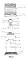
- FIG. 2is an exploded view of the LED beacon shown in FIG. 1 ;
- FIG. 3is a perspective view of the LED beacon shown in FIGS. 1 and 2 with the cap or drum providing a cylindrical fresnel collimating lens not shown in the drawing so as to illustrate the internals of the beacon;
- FIG. 4is an exploded view of the condensing lens system of the beacon shown in FIGS. 1 , 2 and 3 ;
- FIG. 5is a multi-part view consisting of FIGS. 5A-5F of a condensing meniscus, coupling lens in the optical system shown in FIG. 4 , wherein FIG. 5A is a sectional view of the lens taken along the line A-A in FIG. 5B ; FIG. 5B is a horizontal sectional view through the lens in a horizontal plane through the center of the lens; FIG. 5C is a perspective view of the lens taken from the right as viewed in FIG. 5A ; FIG. 5D is an elevational view of the lens looking from the right side of FIG. 5A ; FIG. 5E is a perspective view of the lens from the inside thereof; and FIG. 5F is a perspective view of the lens from the outside thereof; and
- FIG. 6is a perspective view of an LED beacon of another embodiment of the present invention showing an LED beam beacon.
- an LED beacon 10having a cylindrical fresnel collimating lens 12 which may be attached to a base 14 via a collar 16 .
- an LED assembly 18Inside the collimating lens 12 is an LED assembly 18 .
- This assembly 18has a central post 20 on which is mounted an array of LEDs, e.g., four in number with one on each side of post 20 .
- the post 20is square in cross-section, and the LEDs are 90° apart.
- the LEDs 22are connected via connectors 24 to a circuit board which is potted in a pan 26 , as best shown in FIGS. 2 and 3 .
- the pan 26is mounted on a spacer 28 which is attached by screws 30 to bars 32 projecting radially from the base 14 (see FIG. 3 ). Another screw 34 attaches the post 20 to the spacer 28 through the pan 26 . Other screws 36 attach the pan 26 to the spacer 28 .
- the fresnel lens 12is referred to herein as of a collimating type, depending on the lens 12 , the lens 12 may be substantially collimating, or other lens may be used for lens 12 to refract light incident thereto to provide a desired illumination pattern exiting beacon 10 .
- Screw threads 38 on a cylindrical portion of the base 14enable the collar 16 of lens 12 to engage base 14 , where collar 16 has screw thread along the inner surface of collar 16 which screw onto threads 38 of base 14 thereby attaching the lens 12 to the base 14 and sealing the assembly 18 and the pan 26 and spacer 28 .
- the sealmay use an o-ring 40 .
- the lens 12may be molded plastic material formed into an inverted cup or dome, which may be a desired color. Such inverted cup or dome has a surface defining fresnel lens 12 inside of which LED assembly 18 is located.
- the circuit boardhas circuit components, such as component 42 which provides circuitry for controlling of, as for example flashing, the LEDs 22 .
- the LED assembly 18has a plurality of meniscus condensing, coupling lenses 50 , one for each of the LEDs 22 .
- the central horizontal plane through which the optical axes of these lenses 50 extendis through the LEDs 22 .
- the lenses 50serve two purposes. First, the lenses 50 shift the focus of the fresnel collimating lens 12 (indicated as f, FIG. 5A ) to the location of the LEDs 22 (indicated as F in FIG. 5A ). Second, as shown in FIG. 1 , the condensing lenses 50 also serve the purpose of condensing the illumination emanating from the LEDs 22 so that such illumination covers (paint) the inside of the fresnel collimating lens 12 . By virtue of the refraction in the lenses 50 , the majority of illumination (approximately ⁇ 73° about the horizontal optical axis) from the LEDs 22 is directed to the collimating lens 12 by virtue of the condensing lenses 50 .
- the lenses 50operate to shift the focus of, and distribute the LED light substantially uniformly to collimating lens 12 thereby efficiently using light from the array of LEDs 22 on post 20 to provide an intense illuminating beacon 10 suitable for use on emergency vehicles, and for other vehicles and industrial applications for warning beacons.
- the meniscus lensesare in four segments each defining angles of 90° so that when assembled on the post 20 , they encompass (external around) the entire post over 360°.
- the lenseshave upper and lower collars 58 which are connected to the post 20 by screws 60 .
- the segmentsmay each be of molded optical material, such as plastic, forming the desired lens shape.
- the LEDs 22 and the connectors 24are on circuit boards 70 to which the LEDs 22 and the connectors 24 are wired.
- Thermal transfer pads 72 of heat conductive materialare sandwiched between the circuit boards 70 and the sides of the post 20 to fill the gap between the boards 70 and the post 20 so as to facilitate the transfer of heat from the LEDs to the ambient via the post.
- the segments of the condensing lens 50are assembled on the post, they are located by flanges 76 on the top thereof and by alignment pins 78 (see FIGS. 5A and 5E ).
- FIG. 5Aillustrates the design of an exemplary condensing lens 50 .
- the lens materialmay be polycarbonate lens material.
- the concave inside of the lens 50has a radius of 0.6782 inches.
- the outer convex surfacehas a radius of 0.6500 inches.
- the thickness of the lens along its optical axisis 1.1 inch and the distance to the LED location, F, is 0.2915 inches.
- the focus of the collimating lens 12is shifted from its actual focus at f, to the position of the LEDs at F, by 0.2915 inches with the exemplary lens design, as shown in FIG. 5A .
- an LED beacon 10having an optical system including a collimating lens 12 and a condensing, coupling lens 50 between the LEDs 22 and the collimating lens 12 , which not only provides for relocation of the focus of the collimating lens 12 , but also enables collimating lenses 12 of various diameter and height to be used with the same array of LEDs 22 .
- FIG. 6another embodiment of the LED beacon is shown in which instead of using collimating optics of fresnel lens 12 , beam forming optics of a collimating (or substantially collimating) reflector 75 is utilized.
- This reflector 75may be a parabolic reflector which can be rotated about the internal optical assembly 18 of the LEDs 22 , post 20 , and adapter optics 50 .
- a rotator mechanism 83 , 84 on a base 82may be attached via grommets 81 to a support structure (not shown, e.g., a vehicle roof, light bar) to provide a rotating LED beam beacon.
- the rotating reflector mechanismmay be of the type in U.S. Pat. No. 5,860,726, issued Jan. 19, 1999, to Richardson, which is herein incorporated by reference.
- the optical assembly 18 and rotator mechanism 83 , 84may be located internally in a transparent or translucent dome, which may of a desired color.
- the reflector 75may also be stationary, instead of rotatable, by removal of the rotator mechanisms 83 , 84 (or non-actuation thereof) to provide a stationary LED beam beacon.
- the optical assembly 18may be the same as described earlier. Although four LEDs 22 on post 20 is preferred, optionally a single LED may be used in optical assembly 18 on one side of post 20 to direct light toward the stationary reflector 75 via the adapter optics 50 . Accordingly, a parabolic reflector 75 that is stationary or can be rotated about the internal optical assembly 18 is provided, but other beam shaping optics may be used depending on the particular application.
- LEDs 22 on post 20may number four, one on each side of the post 20 in optical assembly 18 . However, more than four LEDs 22 may be used, such as eight in number by providing two LEDs 22 on each side of post 20 , but other number of LEDs may be used.
- the present inventionbroadly relates to use of an adapter optic (the condensing coupling lenses 50 ) in a horizontal array with horizontal LED's so as to obtain the full benefits of LED illumination vs. conventional incandescent, halogen or strobe illumination.
- the collimating, fresnel lensesdo not have to be redesigned to accommodate LED illumination.
- Existing domes providing collimating lens for the beacon, and tooling for producing the domesmay be used thereby reducing development effort and financial cost in providing an LED beacon.
- the adapter opticsenables increase of the light output significantly over prior LED designs even where no optics internal of the dome or outside lens is used.
Landscapes
- Engineering & Computer Science (AREA)
- General Engineering & Computer Science (AREA)
- Mechanical Engineering (AREA)
- Non-Portable Lighting Devices Or Systems Thereof (AREA)
Abstract
Description
Claims (19)
Priority Applications (4)
| Application Number | Priority Date | Filing Date | Title |
|---|---|---|---|
| US12/806,284US8662702B2 (en) | 2009-09-08 | 2010-08-09 | LED beacon |
| CA2714447ACA2714447C (en) | 2009-09-08 | 2010-09-03 | Led beacon |
| US12/886,832US11228735B2 (en) | 2003-01-14 | 2010-09-21 | LED or laser project light has more than 1 functions |
| US13/354,316US8840268B2 (en) | 2009-09-08 | 2012-01-19 | Multicolor LED beacon |
Applications Claiming Priority (2)
| Application Number | Priority Date | Filing Date | Title |
|---|---|---|---|
| US27611509P | 2009-09-08 | 2009-09-08 | |
| US12/806,284US8662702B2 (en) | 2009-09-08 | 2010-08-09 | LED beacon |
Related Parent Applications (2)
| Application Number | Title | Priority Date | Filing Date |
|---|---|---|---|
| US12/566,322ContinuationUS20100033990A1 (en) | 2002-11-04 | 2009-09-24 | Multiple functions led night light with air freshener |
| US12/806,285ContinuationUS8428934B2 (en) | 2003-01-14 | 2010-08-09 | Prose style morphing |
Related Child Applications (3)
| Application Number | Title | Priority Date | Filing Date |
|---|---|---|---|
| US12/806,285ContinuationUS8428934B2 (en) | 2003-01-14 | 2010-08-09 | Prose style morphing |
| US12/806,711ContinuationUS8074541B2 (en) | 2003-01-14 | 2010-08-19 | Portable tool kit with auto-release clasp and expandable tools |
| US13/354,316Continuation-In-PartUS8840268B2 (en) | 2009-09-08 | 2012-01-19 | Multicolor LED beacon |
Publications (2)
| Publication Number | Publication Date |
|---|---|
| US20110058370A1 US20110058370A1 (en) | 2011-03-10 |
| US8662702B2true US8662702B2 (en) | 2014-03-04 |
Family
ID=43647644
Family Applications (2)
| Application Number | Title | Priority Date | Filing Date |
|---|---|---|---|
| US12/806,284Active2032-05-18US8662702B2 (en) | 2003-01-14 | 2010-08-09 | LED beacon |
| US13/354,316Active2030-08-26US8840268B2 (en) | 2009-09-08 | 2012-01-19 | Multicolor LED beacon |
Family Applications After (1)
| Application Number | Title | Priority Date | Filing Date |
|---|---|---|---|
| US13/354,316Active2030-08-26US8840268B2 (en) | 2009-09-08 | 2012-01-19 | Multicolor LED beacon |
Country Status (2)
| Country | Link |
|---|---|
| US (2) | US8662702B2 (en) |
| CA (1) | CA2714447C (en) |
Cited By (13)
| Publication number | Priority date | Publication date | Assignee | Title |
|---|---|---|---|---|
| WO2015168186A1 (en)* | 2014-04-28 | 2015-11-05 | Bizwerks, Llc | Led venue lighting system and method |
| US9631779B2 (en) | 2013-08-15 | 2017-04-25 | Star Headlight & Lantern Co., Inc. | Optical system utilizing LED illumination for a light bar, and light bar having same |
| KR101797857B1 (en) | 2016-04-21 | 2017-11-15 | 한국광기술원 | Aviation warning light with asymmetry angular distribution of luminous intensity |
| US10030826B2 (en) | 2015-12-28 | 2018-07-24 | Federal Signal Corporation | Light beacon lens |
| US10041635B2 (en) | 2014-11-19 | 2018-08-07 | Man Yin Lam | Lighting and diffuser apparatus for a flashlight |
| US10143250B2 (en) | 2014-11-07 | 2018-12-04 | Richard R. W. Schulz | Removable clothing patches and associated methods |
| US10309595B1 (en) | 2017-07-19 | 2019-06-04 | Star Headlight & Lantern Co., Inc. | LED beacons |
| US10720031B1 (en) | 2018-06-04 | 2020-07-21 | Star Headlight & Lantern Co., Inc. | Warning light beacons |
| US10738967B2 (en) | 2018-05-07 | 2020-08-11 | Sportsbeams Lighting, Inc. | Venue light including variable LED array size etched lens and segmented reflector |
| US10823370B2 (en) | 2018-09-20 | 2020-11-03 | Federal Signal Corporation | Light beacon lens |
| US12007098B2 (en) | 2018-08-17 | 2024-06-11 | Sportsbeams Lighting, Inc. | Sports light having single multi-function body |
| USD1044551S1 (en) | 2022-09-12 | 2024-10-01 | Star Safety Technologies, Llc | Warning light beacon |
| US12247729B2 (en) | 2015-02-04 | 2025-03-11 | Milwaukee Electric Tool Corporation | Light |
Families Citing this family (30)
| Publication number | Priority date | Publication date | Assignee | Title |
|---|---|---|---|---|
| DE102009044388A1 (en)* | 2009-11-02 | 2011-05-05 | Semperlux Aktiengesellschaft - Lichttechnische Werke - | Outdoor light and high pressure lamp replacement |
| US20110121734A1 (en)* | 2009-11-25 | 2011-05-26 | Ryan Bernard Pape | Light emitting diode (led) beacon |
| US9016896B1 (en) | 2011-02-23 | 2015-04-28 | Hughey & Phillips, Llc | Obstruction lighting system |
| US9013331B2 (en) | 2011-03-17 | 2015-04-21 | Hughey & Phillips, Llc | Lighting and collision alerting system |
| EP3299704A1 (en) | 2011-03-17 | 2018-03-28 | Hughey & Phillips, LLC | Lighting system |
| WO2012158628A2 (en)* | 2011-05-13 | 2012-11-22 | Toyota Tsusho America, Inc. | Reusable high power led module and methods thereof |
| FI124979B (en)* | 2011-06-30 | 2015-04-15 | Obelux Oy | Flight obstacle light |
| TWI435993B (en)* | 2011-11-16 | 2014-05-01 | Univ Nat Central | Special lamps with light changes |
| US9175827B2 (en)* | 2012-05-09 | 2015-11-03 | Lee Clore | Indicator light tower technology |
| WO2014011873A2 (en)* | 2012-07-12 | 2014-01-16 | Spx Corporation | Beacon light having a lens |
| DK2888522T3 (en) | 2012-08-22 | 2018-11-12 | Spx Corp | LIGHT WITH AN OMNI DIRECTIONAL SURROUNDING LIGHT COLLECTOR |
| US9228713B2 (en)* | 2012-08-31 | 2016-01-05 | Federal Signal Corporation | Light beacon assembly |
| DE102013103673A1 (en)* | 2012-12-14 | 2014-06-18 | Weidmüller Interface GmbH & Co. KG | Lighting device and lighting arrangement for illuminating the interior of a tower or tunnel |
| US10696210B2 (en)* | 2013-02-25 | 2020-06-30 | Rensselaer Polytechnic Institute | Low luminance lighting |
| EP2808600B1 (en)* | 2013-05-27 | 2019-06-26 | Induperm A/S | Omnidirectional air field light |
| USD770317S1 (en)* | 2013-07-19 | 2016-11-01 | Weidmueller Interface Gmbh & Co. Kg | LED lights |
| US8998443B1 (en) | 2013-10-01 | 2015-04-07 | Spx Corporation | Beacon light having a lens |
| CN103591606B (en)* | 2013-10-23 | 2015-05-13 | 宁波新海电气股份有限公司 | Device for detecting flame and pressure of lighter |
| AU2016256833B2 (en)* | 2014-04-28 | 2018-11-08 | Orion Safety & Control Systems Pty Ltd | Rotating beacon |
| WO2015164922A2 (en)* | 2014-04-28 | 2015-11-05 | Orca Group Limited | Rotating beacon |
| BR202015003430Y1 (en)* | 2015-02-13 | 2020-05-19 | Balbinot Mauricio | constructive arrangement in intermittent lighting equipment applied to special vehicles |
| CA2927419A1 (en) | 2015-04-16 | 2016-10-16 | Hughey & Phillips, Llc | Obstruction lighting system configured to emit visible and infrared light |
| US9719657B2 (en)* | 2015-06-09 | 2017-08-01 | Hazard Systems Pty Ltd. | Low-profile optical warning system |
| US11178741B1 (en) | 2015-12-22 | 2021-11-16 | Hughey & Phillips, Llc | Lighting system configured to emit visible and infrared light |
| US10373451B2 (en) | 2017-11-09 | 2019-08-06 | Banner Engineering Corp. | Augmented sensing tower light assembly |
| CN108980889A (en)* | 2018-06-23 | 2018-12-11 | 刘道灵 | A kind of automatic lighter firing information collecting device |
| US10609266B2 (en)* | 2018-08-21 | 2020-03-31 | Rockwell Automation Technologies, Inc. | Camera for wide field of view with an arbitrary aspect ratio |
| GB2587403A (en)* | 2019-09-27 | 2021-03-31 | Techna Int Ltd | Vehicle Beacon |
| WO2022138211A1 (en)* | 2020-12-24 | 2022-06-30 | 日亜化学工業株式会社 | Light-emitting module and lens |
| CN112736590A (en)* | 2020-12-25 | 2021-04-30 | 孙丽华 | Socket with protect function with electrical apparatus plug |
Citations (10)
| Publication number | Priority date | Publication date | Assignee | Title |
|---|---|---|---|---|
| US3221162A (en) | 1963-05-08 | 1965-11-30 | Elastic Stop Nut Corp | Marine lantern assembly |
| US5237490A (en) | 1992-07-07 | 1993-08-17 | Ferng Shing Lai | Solar power-operated, construction work warning lamp with focusing device for intensifying the intensity of light |
| US5860726A (en) | 1997-05-05 | 1999-01-19 | Star Headlight And Lantern Co. Inc. | Rotator mounting system |
| US6425678B1 (en) | 1999-08-23 | 2002-07-30 | Dialight Corporation | Led obstruction lamp |
| US6483439B1 (en) | 1999-10-14 | 2002-11-19 | Star Headlight And Lantern Co., Inc. | Multi color and omni directional warning lamp |
| US6626557B1 (en) | 1999-12-29 | 2003-09-30 | Spx Corporation | Multi-colored industrial signal device |
| US20060181879A1 (en)* | 1999-06-08 | 2006-08-17 | 911Ep, Inc. | Rotational LED reflector |
| US7252405B2 (en) | 2002-11-19 | 2007-08-07 | Automatic Power, Inc. | LED lantern with fresnel lens |
| US20080048553A1 (en)* | 2006-07-31 | 2008-02-28 | 3M Innovative Company | Led source with hollow collection lens |
| US7534009B2 (en) | 2004-12-08 | 2009-05-19 | Automatic Power, Inc. | Dual LED point-source assembly |
Family Cites Families (1)
| Publication number | Priority date | Publication date | Assignee | Title |
|---|---|---|---|---|
| US20080036972A1 (en)* | 2006-07-31 | 2008-02-14 | 3M Innovative Properties Company | Led mosaic |
- 2010
- 2010-08-09USUS12/806,284patent/US8662702B2/enactiveActive
- 2010-09-03CACA2714447Apatent/CA2714447C/enactiveActive
- 2012
- 2012-01-19USUS13/354,316patent/US8840268B2/enactiveActive
Patent Citations (10)
| Publication number | Priority date | Publication date | Assignee | Title |
|---|---|---|---|---|
| US3221162A (en) | 1963-05-08 | 1965-11-30 | Elastic Stop Nut Corp | Marine lantern assembly |
| US5237490A (en) | 1992-07-07 | 1993-08-17 | Ferng Shing Lai | Solar power-operated, construction work warning lamp with focusing device for intensifying the intensity of light |
| US5860726A (en) | 1997-05-05 | 1999-01-19 | Star Headlight And Lantern Co. Inc. | Rotator mounting system |
| US20060181879A1 (en)* | 1999-06-08 | 2006-08-17 | 911Ep, Inc. | Rotational LED reflector |
| US6425678B1 (en) | 1999-08-23 | 2002-07-30 | Dialight Corporation | Led obstruction lamp |
| US6483439B1 (en) | 1999-10-14 | 2002-11-19 | Star Headlight And Lantern Co., Inc. | Multi color and omni directional warning lamp |
| US6626557B1 (en) | 1999-12-29 | 2003-09-30 | Spx Corporation | Multi-colored industrial signal device |
| US7252405B2 (en) | 2002-11-19 | 2007-08-07 | Automatic Power, Inc. | LED lantern with fresnel lens |
| US7534009B2 (en) | 2004-12-08 | 2009-05-19 | Automatic Power, Inc. | Dual LED point-source assembly |
| US20080048553A1 (en)* | 2006-07-31 | 2008-02-28 | 3M Innovative Company | Led source with hollow collection lens |
Cited By (17)
| Publication number | Priority date | Publication date | Assignee | Title |
|---|---|---|---|---|
| US9631779B2 (en) | 2013-08-15 | 2017-04-25 | Star Headlight & Lantern Co., Inc. | Optical system utilizing LED illumination for a light bar, and light bar having same |
| US10738990B2 (en) | 2014-04-28 | 2020-08-11 | Sportsbeams Lighting, Inc. | Single optic LED venue lighting fixture |
| WO2015168186A1 (en)* | 2014-04-28 | 2015-11-05 | Bizwerks, Llc | Led venue lighting system and method |
| US9341362B2 (en) | 2014-04-28 | 2016-05-17 | Bizwerks, Llc | LED venue lighting system with first and second housing having an air passage therebetween |
| US10317065B2 (en) | 2014-04-28 | 2019-06-11 | Sportsbeams Lighting, Inc. | LED lighting system with forced air cooling |
| US10143250B2 (en) | 2014-11-07 | 2018-12-04 | Richard R. W. Schulz | Removable clothing patches and associated methods |
| US10701995B2 (en) | 2014-11-07 | 2020-07-07 | Richard R W Schulz | Removable clothing patch and associated methods |
| US10041635B2 (en) | 2014-11-19 | 2018-08-07 | Man Yin Lam | Lighting and diffuser apparatus for a flashlight |
| US12247729B2 (en) | 2015-02-04 | 2025-03-11 | Milwaukee Electric Tool Corporation | Light |
| US10030826B2 (en) | 2015-12-28 | 2018-07-24 | Federal Signal Corporation | Light beacon lens |
| KR101797857B1 (en) | 2016-04-21 | 2017-11-15 | 한국광기술원 | Aviation warning light with asymmetry angular distribution of luminous intensity |
| US10309595B1 (en) | 2017-07-19 | 2019-06-04 | Star Headlight & Lantern Co., Inc. | LED beacons |
| US10738967B2 (en) | 2018-05-07 | 2020-08-11 | Sportsbeams Lighting, Inc. | Venue light including variable LED array size etched lens and segmented reflector |
| US10720031B1 (en) | 2018-06-04 | 2020-07-21 | Star Headlight & Lantern Co., Inc. | Warning light beacons |
| US12007098B2 (en) | 2018-08-17 | 2024-06-11 | Sportsbeams Lighting, Inc. | Sports light having single multi-function body |
| US10823370B2 (en) | 2018-09-20 | 2020-11-03 | Federal Signal Corporation | Light beacon lens |
| USD1044551S1 (en) | 2022-09-12 | 2024-10-01 | Star Safety Technologies, Llc | Warning light beacon |
Also Published As
| Publication number | Publication date |
|---|---|
| CA2714447A1 (en) | 2011-03-08 |
| US8840268B2 (en) | 2014-09-23 |
| US20120182730A1 (en) | 2012-07-19 |
| US20110058370A1 (en) | 2011-03-10 |
| CA2714447C (en) | 2017-02-14 |
Similar Documents
| Publication | Publication Date | Title |
|---|---|---|
| US8662702B2 (en) | LED beacon | |
| US10139079B2 (en) | LED illumination assembly with collimating optic | |
| US9995462B2 (en) | Circular LED optic and heat sink module | |
| KR101028201B1 (en) | Lens and lighting unit having same | |
| US7441929B2 (en) | Lighting unit having a plurality of curved surface elements | |
| US9466773B2 (en) | Semiconductor light device including a lens having a light deflection structure | |
| EP0752081B1 (en) | Lightning device | |
| US20060291201A1 (en) | Side-emitting collimator | |
| US20180135831A1 (en) | Beam Forming Optic for LED | |
| CN106068466A (en) | There are the lens of the convex facet of dense distribution at the plane of incidence and exit facet | |
| JPH04230901A (en) | Garden lantern and lens for garden lantern | |
| US20140177234A1 (en) | Lens and light source module incorporating the same | |
| US9804321B1 (en) | LED optics for bulbs and luminaires | |
| WO2008110796A1 (en) | Beacons and other light-emitting units | |
| CN101963327B (en) | Refection cover and lighting device | |
| US20110134636A1 (en) | Led traffic signal device | |
| US8033696B2 (en) | Heat sinks and other thermal management for solid state devices and modular solid state systems | |
| US9010963B2 (en) | Lens member for directing light in a square pattern | |
| EP2912368B1 (en) | Optical cover for a light emitting module | |
| US7470045B2 (en) | Assembly for directed shading of outside lighting | |
| US9097395B2 (en) | Lens with divergent structure and backlight module incorporating the same | |
| KR20100081732A (en) | Light emitting apparatus | |
| US8746936B2 (en) | Luminaire and optical component | |
| KR101071727B1 (en) | Lighting equipment | |
| GB2297149A (en) | Lighting apparatus |
Legal Events
| Date | Code | Title | Description |
|---|---|---|---|
| AS | Assignment | Owner name:STAR HEADLIGHT & LANTERN CO., INC., NEW YORK Free format text:ASSIGNMENT OF ASSIGNORS INTEREST;ASSIGNORS:DATZ, R. MICHAEL;VUKOSIC, STEPHEN T.;REEL/FRAME:024844/0251 Effective date:20100806 | |
| STCF | Information on status: patent grant | Free format text:PATENTED CASE | |
| MAFP | Maintenance fee payment | Free format text:PAYMENT OF MAINTENANCE FEE, 4TH YR, SMALL ENTITY (ORIGINAL EVENT CODE: M2551) Year of fee payment:4 | |
| MAFP | Maintenance fee payment | Free format text:PAYMENT OF MAINTENANCE FEE, 8TH YR, SMALL ENTITY (ORIGINAL EVENT CODE: M2552); ENTITY STATUS OF PATENT OWNER: SMALL ENTITY Year of fee payment:8 | |
| AS | Assignment | Owner name:JPMORGAN CHASE BANK, N.A., OHIO Free format text:ASSIGNMENT OF ASSIGNORS INTEREST;ASSIGNOR:STAR SAFETY TECHNOLOGIES, LLC;REEL/FRAME:064228/0688 Effective date:20230603 | |
| AS | Assignment | Owner name:JPMORGAN CHASE BANK, N.A., OHIO Free format text:CORRECTIVE ASSIGNMENT TO CORRECT THE NATURE OF CONVEYANCE PREVIOUSLY RECORDED AT REEL: 064228 FRAME: 0688. ASSIGNOR(S) HEREBY CONFIRMS THE SECURITY INTEREST;ASSIGNOR:STAR SAFETY TECHNOLOGIES, LLC;REEL/FRAME:064274/0456 Effective date:20230603 | |
| AS | Assignment | Owner name:STAR SAFETY TECHNOLOGIES, LLC, NEW YORK Free format text:ASSIGNMENT OF ASSIGNORS INTEREST;ASSIGNOR:STAR HEADLIGHT & LANTERN CO., INC.;REEL/FRAME:064554/0013 Effective date:20230417 |