US8662605B2 - Mobile technology cabinet - Google Patents
Mobile technology cabinetDownload PDFInfo
- Publication number
- US8662605B2 US8662605B2US13/397,048US201213397048AUS8662605B2US 8662605 B2US8662605 B2US 8662605B2US 201213397048 AUS201213397048 AUS 201213397048AUS 8662605 B2US8662605 B2US 8662605B2
- Authority
- US
- United States
- Prior art keywords
- cabinet
- work platform
- monitor
- track
- pivot pin
- Prior art date
- Legal status (The legal status is an assumption and is not a legal conclusion. Google has not performed a legal analysis and makes no representation as to the accuracy of the status listed.)
- Expired - Fee Related, expires
Links
Images


Classifications
- B—PERFORMING OPERATIONS; TRANSPORTING
- B62—LAND VEHICLES FOR TRAVELLING OTHERWISE THAN ON RAILS
- B62B—HAND-PROPELLED VEHICLES, e.g. HAND CARTS OR PERAMBULATORS; SLEDGES
- B62B3/00—Hand carts having more than one axis carrying transport wheels; Steering devices therefor; Equipment therefor
- B62B3/02—Hand carts having more than one axis carrying transport wheels; Steering devices therefor; Equipment therefor involving parts being adjustable, collapsible, attachable, detachable or convertible
- A—HUMAN NECESSITIES
- A61—MEDICAL OR VETERINARY SCIENCE; HYGIENE
- A61B—DIAGNOSIS; SURGERY; IDENTIFICATION
- A61B50/00—Containers, covers, furniture or holders specially adapted for surgical or diagnostic appliances or instruments, e.g. sterile covers
- A61B50/10—Furniture specially adapted for surgical or diagnostic appliances or instruments
- A61B50/13—Trolleys, e.g. carts
- B—PERFORMING OPERATIONS; TRANSPORTING
- B62—LAND VEHICLES FOR TRAVELLING OTHERWISE THAN ON RAILS
- B62B—HAND-PROPELLED VEHICLES, e.g. HAND CARTS OR PERAMBULATORS; SLEDGES
- B62B2202/00—Indexing codes relating to type or characteristics of transported articles
- B62B2202/56—Computers; Screens
- B—PERFORMING OPERATIONS; TRANSPORTING
- B62—LAND VEHICLES FOR TRAVELLING OTHERWISE THAN ON RAILS
- B62B—HAND-PROPELLED VEHICLES, e.g. HAND CARTS OR PERAMBULATORS; SLEDGES
- B62B2205/00—Hand-propelled vehicles or sledges being foldable or dismountable when not in use
- B62B2205/003—Hand-propelled vehicles or sledges being foldable or dismountable when not in use with actuation mechanisms which drive the folding or unfolding operation
- B—PERFORMING OPERATIONS; TRANSPORTING
- B62—LAND VEHICLES FOR TRAVELLING OTHERWISE THAN ON RAILS
- B62B—HAND-PROPELLED VEHICLES, e.g. HAND CARTS OR PERAMBULATORS; SLEDGES
- B62B2206/00—Adjustable or convertible hand-propelled vehicles or sledges
- B62B2206/06—Adjustable or convertible hand-propelled vehicles or sledges adjustable in height
Definitions
- Cartsare known for transporting information technology (IT) equipment, such as a computer and monitor, power supply and the like, in health care environments such as hospitals. Such carts may be moved between patient locations such as patient rooms or beds where a user, such as a health care provider, may use the IT equipment to access and/or record information at the point of care.
- ITinformation technology
- the typical cartis supported on wheels and includes a platform or platforms for supporting the IT equipment. These carts tend to have a large footprint and intrude into the surrounding space. Further, at least some of the IT equipment is normally exposed at all times.
- a mobile technology cabinetcomprises a compartment having a work platform mounted for rotational motion between a substantially vertical first storage position and a first deployed position. One end of the work platform rises from a first lower position to a second higher position as the work platform is rotated from the first storage position to the first deployed position.
- a monitor supportis operatively connected to the work platform such that movement of the work platform between the first storage position and the first deployed position raises the monitor support from a second storage position to a second deployed position.
- a mobile technology cabinetcomprises a base supported for movement on rollers.
- a frameextends from the base and supports a cabinet such that the cabinet is movable between a raised position and a lowered position.
- the cabinethas a compartment where the compartment has a work platform mounted for rotational motion between a substantially vertical first storage position and a first deployed position. One end of the work platform rises from a first lower position to a second higher position as the work platform is rotated from the first storage position to the first deployed position.
- a monitor supportis operatively connected to the work platform such that movement of the work platform between the first storage position and the first deployed position raises the monitor from a second storage position to a second deployed position.
- a method of operating a mobile cabinetcomprises storing a monitor and a work platform in a cabinet with the work platform arranged in front of the monitor with the work platform and the monitor completely contained in the cabinet; and rotating the work platform relative to the cabinet to simultaneously deploy a substantially horizontal work surface and to raise the monitor.
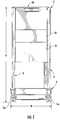
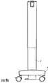
- FIG. 1is a plan view of one embodiment of the mobile technology cabinet of the invention.
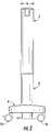
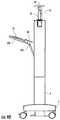
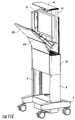
- FIG. 2is a side view of the technology cabinet of FIG. 1 .
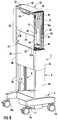
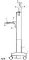
- FIG. 3is a back perspective view of the technology cabinet of FIG. 1 .
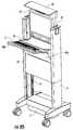
- FIG. 4is a front perspective view of the technology cabinet of FIG. 1 .
- FIG. 5is a top view of the technology cabinet of FIG. 1 .
- FIG. 6is a perspective view of the technology cabinet of FIG. 1 in the storage position with a portion of the frame removed.
- FIG. 7is a perspective view of the technology cabinet of FIG. 1 in the deployed position with a portion of the frame removed.
- FIGS. 8 a through 8 eare perspective views showing the operation of the technology cabinet of FIG. 1 .
- FIGS. 9 a through 9 eare side views showing the operation of the technology cabinet of FIG. 1 .
- FIGS. 10 a through 10 eare perspective views showing the operation of the technology cabinet of FIG. 1 with a portion of the frame removed.
- FIGS. 11 a through 11 eare side views showing the operation of the technology cabinet of FIG. 1 with a portion of the frame removed.
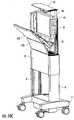
- FIG. 12is a perspective view of the technology cabinet of FIG. 1 in the raised and deployed position with a portion of the cabinet removed.
- FIG. 13is a perspective view of the technology cabinet of FIG. 1 in the lowered and deployed position with a portion of the cabinet removed.
- FIG. 14is a perspective cut-away view of the base of the technology cabinet of FIG. 1 .
- the mobile cabinetcomprises a frame 2 mounted on a base 4 for movement over a floor or other surface.
- the frame 2comprises a pair of vertical uprights 6 and 8 that extend vertically from and are supported on the base 4 .
- the height H of the unit in the closed, raised position shown in FIGS. 1 through 4is approximately five feet such that most adults will be able to push the unit and see over the unit without their view being obstructed.
- the uprights 6 and 8are spaced from one another a sufficient distance to retain a monitor, computer and power system between the uprights.
- the unithas a width W of approximately two feet.
- the uprights 6 and 8have a depth D that is wide enough to accommodate a flat panel monitor or similar display device and a computer.
- the uprights 6 and 8have a depth of approximately six inches.
- the cabinetwhen in the closed position, has a small footprint and a compact design that occupies a minimum amount of space where the IT equipment may be completely enclosed and hidden from view.
- the base 4is supported for rolling movement on a plurality of rollers or wheels 16 such that a user may push the cabinet across a floor.
- pivoting caster wheelsare used where two of the caster wheels 16 a are lockable to lock the cabinet in position when not being transported.
- any suitable device that provides the cabinet with mobilitymay be used.
- one or more of the wheelsmay be driven by a powered drive system if desired.
- the base 4comprises a compartment or compartments 14 for storing the battery 10 and power supply 12 that provide power to the on board equipment including monitor 42 and computer/CPU 43 .
- the compartments 14may be closed by covers 15 (see, FIGS. 3 and 4 ) that isolate and protect the battery 10 and power supply 12 .
- the uprights 6 and 8may be formed of telescoping lower sections 6 a , 8 a and upper sections 6 b , 8 b, respectively, where the upper sections 6 b , 8 b are mounted on rails 9 formed on the lower sections 6 a , 8 a such that the upper sections 6 b , 8 b may slide over the lower sections 6 a , 8 a between raised and lowered positions.
- the height of the user equipment in the deployed positionmay be disposed comfortably for a standing user while in the lowered position ( FIG. 13 ) the equipment may be disposed comfortably for a seated user.
- the cabinetmay be positioned at any intermediate height to accommodate a variety of user heights and uses.
- a lift mechanismmay be provided to act as a counterweight to the movable section of the cabinet to assist the user in raising and lowering the movable section.
- the lift mechanismmay comprise a pneumatic cylinder, weighted pulley system or the like.
- the lift mechanismmay be actuated by a foot pedal 11 where the user presses the foot pedal 11 to release or actuate the lift mechanism.
- the lift mechanismmay comprise a motorized system that automatically raises and lowers the upper unit.
- the uprights 6 and 8may be made non-adjustable if height adjustment is not desired.
- the lift mechanismcomprises a locking gas spring 100 disposed in each of the uprights 6 , 8 . While in a preferred embodiment a gas spring 100 is located in each of the uprights 6 , 8 a single gas spring may be used if desired. Reference will be made to the gas spring arrangement in upright 6 it being understood that a similar gas spring arrangement is located in upright 8 .
- the gas spring 100has one end connected to one of the movable upright section 6 b or stationary upright section 6 a and the other end connected to the other of the movable upright section 6 b or stationary upright section 6 a .
- the gas spring 100may have a cylinder connected to one of the movable upright section 6 b or stationary upright section 6 a and a piston connected to the other of the movable upright section 6 b or stationary upright section 6 a .
- the gas spring 100may also be connected between other of the movable components and the stationary components such as between base 4 and the cabinet 20 provided that the gas spring is able to assist movement of the movable section of the cabinet.
- Each gas spring 100is provided with a release pin 102 that, when depressed, releases the gas spring 100 such that the piston may move relative to the cylinder. When the pin 102 is not depressed the gas spring 100 is locked in position.
- an actuator cam 104is mounted for pivoting movement adjacent to the pin 102 .
- the actuator cam 104may be rotated into engagement with the pin 102 to unlock the gas spring 100 .
- an actuator rod 106is connected to the between the actuator cams 104 located in uprights 6 and 8 such that motion of the actuator rod 106 results in the simultaneous rotation of both cams 104 .
- a foot pedal link 108connects the actuator rod 106 to foot pedal 11 such that when the user depresses the foot pedal lithe movement of the foot pedal 11 is transferred to the actuator rod 106 via the link 108 . Depressing pedal 11 rotates the cams 104 into engagement with the release pins 102 to unlock the gas springs 100 .
- a springreturns the foot pedal 11 , link 108 , rod 106 and cams 104 to the locked position when the foot pedal 11 is released.
- the gas springs 100are locked in position.
- the userdepresses the pedal 11 to unlock the gas springs 100 .
- the gas springs 100raise the cabinet absent any counteracting downward force.
- the userdepresses pedal 11 to unlock the gas springs 100 .
- the usermay push down on the cabinet 20 or wall 62 to lower the cabinet. Once the cabinet is positioned at the desired height the user may release the foot pedal 11 to lock the gas springs 100 thereby locking the cabinet at the desired height.
- Frame 2supports a cabinet 20 that supports a monitor 42 , a computer/CPU 43 and user input devices such as a mouse and keyboard 51 .
- Cabinet 20comprises a first compartment 22 that supports computer/CPU 43 and/or other IT equipment such as a wireless access point, router or the like and that has space for cable management.
- the first compartment 22may be accessed through a door for maintenance or the like where the door is lockable for security purposes. The door is shown removed in FIGS. 12 and 13 .
- the first compartment 22 , computer/CPU 43 and other IT equipmentmove with cabinet 20 such that the computer/CPU 43 moves with the monitor 42 , keyboard 51 , mouse and other user equipment. Moving the computer/CPU 43 with the user equipment simplifies the cable management between these components because the cables do not have to move between the computer/CPU 43 and the user equipment.
- the cable management systemcomprises a telescoping cable channel 80 that telescopes when the cabinet 20 is raised and lowered on the frame 2 .
- the channel 80comprises a first channel section 82 that is fixed to base 4 .
- a second channel section 84fits over and moves relative to the first channel section 82 such that the first channel section 82 may be telescopically received in the second channel section 84 .
- the second channel section 84is slidably mounted in an aperture 86 formed in the bottom of compartment 22 .
- the first channel section 82can slide into and out of the second channel section 84 and the second channel section 84 can slide into and out of the compartment 22 .
- the first channel section 82 and second channel section 84are extended from one another and extend outside of compartment 22 as shown in FIG. 12 .
- the first channel section 82slides inside of the second channel section 84 and both sections slide into the compartment 22 such that the cabinet may be lowered to base 4 as shown in FIG. 13 .
- Cables 88run from the power supply 12 to the computer/CPU 43 and monitor 42 through the cable channel 80 .
- the cables 88remain essentially stationary as the cabinet 20 is raised and lowered. When the cabinet 20 is in the lowered position the cables 88 extend out of the top of the collapsed cable channel 80 to form a service loop 90 that can be accessed by service personnel.
- the cabinet 20comprises a second compartment 26 for holding the monitor 42 , user input devices such as keyboard 51 and a work platform 50 .
- the second compartment 26is defined by a cover 44 and a stationary front wall 60 .
- the back wall 62 of the second compartment 26moves to open the cabinet and reveal the monitor 42 , work platform 50 and keyboard 51 and to position these components relative to one another in a proper ergonomic position.
- the terms “front” and “back”are used herein for ease of explanation to describe the orientation between the components, in actual use either side of the cabinet may constitute the front or back of the device.
- the second compartment 26opens and closes as will hereinafter be described such that the user equipment stored in compartment 26 may be moved between a deployed position where the equipment may be used by the user and a storage position where the user equipment is contained in the cabinet and hidden from view.
- the second compartment 26opens simply with a single motion where all of the user equipment is quickly and easily accessed with a single movement of the user.
- a motion guide 30Located in the interior of upright 6 is a motion guide 30 and located on the interior of upright 8 is a motion guide 32 .
- the motion guides 30 and 32are mirror images of one another and are disposed opposite to one another to support the monitor 40 and work platform 50 as they are moved between the deployed and storage positions.
- Each motion guide 30 , 32comprises a plate or other structure that defines a monitor track 34 and a platform track 36 .
- the tracks 34 , 36comprise grooves or slots formed in the plate although the tracks may be formed by other structures.
- the monitor track 34receives a pivot pin 38 that is fixed to the monitor housing 40 such that the pin can slide and rotate in track 34 .
- the monitor housing 40supports monitor 42 such that movement of the monitor housing 40 likewise moves the monitor 42 .
- a cover 44may be secured to the top of the monitor housing 40 such that raising the monitor housing 40 also raises the cover 44 .
- the cover 44may be attached to the cabinet by a hinge such that it flips open upon opening of the cabinet.
- the cover 44may be omitted if desired in which case the monitor housing 40 does not have to extend to the top of the cabinet.
- the monitor track 34extends substantially vertically in the guides 30 , 32 such that the monitor housing 40 and monitor 42 move substantially vertically.
- the top end of track 34is formed with a recess or notch 46 that extends toward the front of the cabinet.
- the platform track 36receives a pivot pin 48 that is fixed to the top rear corner of work platform 50 such that the pin 48 can slide and rotate in track 36 .
- Pivot pin 48also pivotably connects the work platform 50 to the monitor housing 40 as best shown in FIGS. 11 a - 11 e such that the work platform 50 is fixed to and may pivot relative to the monitor housing 40 about pin 48 .
- the work platform 50defines a surface 50 a that may be used as a mouse support or as a desk.
- the work platform 50has a first portion 52 that defines the horizontal surface 50 a when the cabinet is opened and a second portion 54 that is disposed at approximately a right angle to first portion 52 .
- the upper edge of the second portion 54is connected to the bottom of the monitor housing 40 by pin 48 such that movement of the work platform 50 causes movement of the monitor housing 40 .
- the platform track 36extends substantially vertically in the guides 30 , 32 .
- a second substantially horizontal track portion 36 aextends from the top end of the platform track 36 at approximately a right angle toward the back of the cabinet.
- a motion damper 70is secured between the monitor housing 40 or the platform 50 and the frame 2 to slow the closing speed of the cabinet to prevent the cabinet from slamming shut.
- the back wall 62comprises a lower panel 62 a and an upper panel 62 b.
- the lower panel 62 ais pivotably connected at its bottom edge to the top of the lower compartment 22 at hinge 63 such that the top end of the lower panel 62 a may pivot away from compartment 22 about the horizontal axis defined by hinge 63 .
- the upper panel 62 bis pivotably connected at its bottom edge to the top of the lower panel 62 a at hinge 66 such that the top end of the upper panel 62 b may pivot relative to the lower panel 62 a and away from compartment 22 about the horizontal axis defined by hinge 66 .
- the bottom front edge of the work platform 50is secured to the inside surface of the upper panel 62 b adjacent hinge 66 in area 68 such that movement of the wall 62 causes movement of the work platform 50 .
- the work platform 50 and the upper panel 62 bcooperate to form an extended work area for the end user.
- the work platform 50 and the upper panel 62 bmay also be formed as a single component where the underside of the work platform forms panel 62 b of wall 62 .
- the panel 62 b and the work platform 50function together to open the cabinet and deploy the user equipment and are referred to collectively as a work platform assembly.
- FIGS. 6 , 8 a , 9 a , 10 a and 11 aA method of operating the cabinet will be described. Assuming that the cabinet is in the closed, storage position of FIGS. 6 , 8 a , 9 a , 10 a and 11 a , the cabinet may be moved by a user on wheels or rollers 16 to locate it in a desired position. To open the cabinet and deploy the user equipment, the user grasps the upper edge 69 of upper panel 62 b and pulls the upper edge outward, FIGS. 8 b , 9 b , 10 b and 11 b . When such a force is applied, the front panel 62 begins to rotate away from the compartment about hinge 63 . As the front panel 62 begins to rotate, pin 48 begins to slide upward in track 36 and the pin 38 begins to slide upward in track 34 .
- the upper panel 62 balso rotates about hinge 66 relative to the lower panel 62 a , FIGS. 8 d , 9 d , 10 d and 11 d .
- work station 50because it is connected to the back side of panel 62 b , also rotates about pin 48 as pin slides upward in track 36 .
- the work platform 50rotates and rises, the work platform 50 pushes the monitor housing 40 upward due to the hinge connection between platform 50 and monitor housing 40 at pin 48 .
- rotating panel 62 to the open positionsimultaneously rotates and raises the work platform 50 and raises the monitor housing 40 and monitor 42 .
- the second compartment 26opens simply with a single motion where all of the user equipment is quickly and easily deployed with a single movement of the user swinging or rotating the work platform assembly from the storage position to the deployed position as described.
- the cabinetremains in the deployed position absent any further action by the end user.
- the loadacts to drive and hold the cabinet in the open position.
- the usermay adjust the height of the cabinet using the telescoping uprights 6 and 8 as previously described.
- the cabinetmay be closed by reversing the movements described above for opening the cabinet.
- the userlifts up on the end 69 of panel 62 b and pushes the panel 62 b inward toward the compartment 22 to rotate the panel 62 closed.
- the pin 48disengages from horizontal slot 36 a which also causes pin 38 to disengage from notch 46 .
- the pins 38 , 48move downward in slots 34 , 36 .
- the damper 70partially supports the weight of the monitor 42 , monitor housing 40 and cabinet to prevent the cabinet from slamming shut during the closing movement.
- the pins 38 , 48move downward in the slots 34 , 36 until they reach the bottom of the slots.
- the panels 62 a and 62 brotate to the vertical closed position.
- the monitor housing 40 and monitor 42slide down to the storage position and the work platform 50 and keyboard 51 rotate and fold into position in front of the monitor 42 .
- the mobile cabinet of the inventionprovides a compact movable work station.
- the mechanism for storing and deploying the monitor and other user equipmentminimizes the physical size of the cabinet such that in the closed position the cabinet is very compact.
- the mobile cabinetminimizes intrusion into the surrounding space when stored. In the hospital environment this consideration is important because such work stations are dispersed throughout hospital where they may intrude into the patient/healthcare provider space. While the mobile cabinet minimizes its intrusion when not in use, it is easy to open and use and provides good ergonomics for the user.
- the ability of the end user to easily move the cabinetprovides an important benefit to the end user that is not found in wall mounted work stations where movement is limited. While providing the benefits of compact size, the mobile cabinet provides a work station that is ergonomically comfortable to use.
- the cabinetWhen stored the actual and perceived size of the mobile cabinet is smaller and less intrusive than a typical computer cart, yet the cabinet offers the same functionality as more intrusive units.
- the narrow profile of the cabinetalso makes it easier for users to navigate around the cabinet and to navigate the cabinet around when in small spaces.
- the mobile cabinethas a furniture grade appearance that satisfies the need for improved aesthetics for work stations.
- the cabinetis provided with a wood grain finish and the frame is made of extruded aluminum. All of these considerations are important for end users, especially in a hospital or healthcare environments, where space is limited and ergonomics for the healthcare professional and interaction with the patient are important.
- the mechanism for opening and closing the cabinetprovides environmentally appropriate aesthetics with optimized ergonomics requiring only one movement of the end user where additional steps to access and use the equipment are not required.
- When the cabinet is openedno additional steps are required to extend a keyboard tray, slide or pivot out a mouse pad, or the like. Ergonomics are optimized in the depth of keyboard to monitor relationship and in the height of keyboard to monitor relationship.
- the mechanism for storing and deploying the monitor and user input devices as described hereinallows the user better visibility past the unit during transport because the user has the ability to see over or around the cabinet while transporting the cabinet.
- the mouse padis located adjacent to the keyboard, providing a generous work surface/mouse pad that also provides storage for the mouse. Because the computer/CPU is stored in the cabinet and moves with the cabinet the mobile cabinet is economical to manufacture and easier to service.
- the cabinetmay be provided with powered, non-powered and/or electronic locking to prevent unauthorized access to the IT equipment.
Landscapes
- Health & Medical Sciences (AREA)
- Engineering & Computer Science (AREA)
- Life Sciences & Earth Sciences (AREA)
- Surgery (AREA)
- Molecular Biology (AREA)
- General Health & Medical Sciences (AREA)
- Nuclear Medicine, Radiotherapy & Molecular Imaging (AREA)
- Veterinary Medicine (AREA)
- Public Health (AREA)
- Biomedical Technology (AREA)
- Heart & Thoracic Surgery (AREA)
- Medical Informatics (AREA)
- Animal Behavior & Ethology (AREA)
- Chemical & Material Sciences (AREA)
- Mechanical Engineering (AREA)
- Combustion & Propulsion (AREA)
- Transportation (AREA)
- Casings For Electric Apparatus (AREA)
Abstract
Description
Claims (18)
Priority Applications (1)
| Application Number | Priority Date | Filing Date | Title |
|---|---|---|---|
| US13/397,048US8662605B2 (en) | 2011-02-18 | 2012-02-15 | Mobile technology cabinet |
Applications Claiming Priority (2)
| Application Number | Priority Date | Filing Date | Title |
|---|---|---|---|
| US201161444283P | 2011-02-18 | 2011-02-18 | |
| US13/397,048US8662605B2 (en) | 2011-02-18 | 2012-02-15 | Mobile technology cabinet |
Publications (2)
| Publication Number | Publication Date |
|---|---|
| US20120212116A1 US20120212116A1 (en) | 2012-08-23 |
| US8662605B2true US8662605B2 (en) | 2014-03-04 |
Family
ID=46652177
Family Applications (1)
| Application Number | Title | Priority Date | Filing Date |
|---|---|---|---|
| US13/397,048Expired - Fee RelatedUS8662605B2 (en) | 2011-02-18 | 2012-02-15 | Mobile technology cabinet |
Country Status (1)
| Country | Link |
|---|---|
| US (1) | US8662605B2 (en) |
Cited By (33)
| Publication number | Priority date | Publication date | Assignee | Title |
|---|---|---|---|---|
| US20130019547A1 (en)* | 2010-04-07 | 2013-01-24 | Sung Yoon Kim | Desk for correct posture and system furniture including the same |
| US20130200586A1 (en)* | 2012-02-03 | 2013-08-08 | Scott Trish | Computing cart with sliding work surface |
| US20140110913A1 (en)* | 2012-10-23 | 2014-04-24 | Spinesmith Partners, L.P. | Automated work station for point-of-care cell and biological fluid processing |
| US20140117635A1 (en)* | 2011-09-30 | 2014-05-01 | Hitachi Aloka Medical, Ltd. | Cart for portable ultrasonic diagnostic device and ultrasonic diagnostic unit |
| US8857828B1 (en)* | 2012-07-10 | 2014-10-14 | Performance Contracting, Inc. | Field access station |
| US20140311050A1 (en)* | 2012-05-25 | 2014-10-23 | Brett Kincaid | Work and Videoconference Assembly |
| US8893628B2 (en)* | 2013-03-04 | 2014-11-25 | Watson Furniture Group, Inc. | Dispatch desk with focal length adjustability |
| US20140368096A1 (en)* | 2013-06-18 | 2014-12-18 | Michael Barry Pachmayr | Flat panel console/cabinet entertainment center |
| US20150166090A1 (en)* | 2013-11-11 | 2015-06-18 | Capsa Solutions | Medical carts with touch-sensitive foot panels, and associated apparatuses and methods |
| US9179493B1 (en) | 2014-04-17 | 2015-11-03 | Huntingdon Telemed, LLC | Medical cart system |
| US9463819B2 (en) | 2014-04-17 | 2016-10-11 | Huntingdon Telemed, Llc. | Portable medical cart system |
| US20170071806A1 (en)* | 2015-09-11 | 2017-03-16 | Stryker Corporation | Telescoping Assembly For Use On A Patient Support Apparatus |
| US9642455B1 (en)* | 2016-11-01 | 2017-05-09 | Sherry Albert | Overbed caddy cart |
| USD792388S1 (en) | 2015-07-22 | 2017-07-18 | Brunswick Corporation | Mobile workstation |
| US9723919B1 (en)* | 2016-02-09 | 2017-08-08 | Symbiote, Inc. | Combination foldable and adjustable workstation |
| US9778707B1 (en) | 2014-08-08 | 2017-10-03 | Performance Contracting, Inc. | System for field access of data |
| US9918550B1 (en) | 2015-07-22 | 2018-03-20 | Brunswick Corporation | Mobile workstation |
| US9933106B2 (en)* | 2013-03-14 | 2018-04-03 | Capsa Solutions, Llc | Height adjustable support |
| US20180168334A1 (en)* | 2015-06-03 | 2018-06-21 | Ergotron, Inc. | Height adjustable device with concealed lift mechanism |
| US10179598B1 (en)* | 2016-07-22 | 2019-01-15 | Harrison J. Goodbinder | Mobile cart |
| US20190328131A1 (en)* | 2017-01-06 | 2019-10-31 | Bae Systems Plc | Workstation |
| US10624451B2 (en)* | 2018-09-11 | 2020-04-21 | Amor Bhattacharya | Therapy desk |
| US10768663B2 (en)* | 2017-08-11 | 2020-09-08 | Xybix Systems, LLC | Apparatus for mounting a plurality of monitors having adjustable distance to a viewer |
| US10980339B2 (en)* | 2017-04-28 | 2021-04-20 | Evans Consoles Corporation | Equipment mounting apparatus for console |
| US11117606B2 (en)* | 2018-04-04 | 2021-09-14 | Brett Lehocky | Personal shopping cart |
| US11234510B2 (en)* | 2019-08-27 | 2022-02-01 | Lenovo (Singapore) Pte. Ltd. | Device and stand assembly |
| US11234787B1 (en) | 2020-11-20 | 2022-02-01 | Stryker Corporation | Manifold for filtering medical waste being drawn under vacuum into a medical waste collection system |
| US11297940B2 (en)* | 2016-10-18 | 2022-04-12 | Dataflex International B.V. | Office workplace system |
| US11419409B2 (en) | 2019-12-12 | 2022-08-23 | David Raymond Koenig | Work station having a multi-purpose work surface |
| US20220273094A1 (en)* | 2020-05-29 | 2022-09-01 | Werxco Pty Ltd | Stowable workstations |
| US11477898B2 (en)* | 2019-03-28 | 2022-10-18 | Lg Electronics Inc. | Display device |
| US11786647B1 (en) | 2022-01-31 | 2023-10-17 | Stryker Corporation | Medical waste collection systems, manifolds, and related methods |
| US20240407548A1 (en)* | 2023-06-08 | 2024-12-12 | Fuding Wenzhang Intelligent Technology Co., Ltd. | Bidirectional flipping mechanism for flipping tv cabinet and a flip tv cabinet |
Families Citing this family (30)
| Publication number | Priority date | Publication date | Assignee | Title |
|---|---|---|---|---|
| US10719149B2 (en)* | 2009-03-18 | 2020-07-21 | Touchtunes Music Corporation | Digital jukebox device with improved user interfaces, and associated methods |
| US8677911B2 (en) | 2011-02-18 | 2014-03-25 | Rubbermaid Incorporated | Technology cart |
| US10453572B1 (en) | 2012-03-01 | 2019-10-22 | Capsa Solutions, Llc | System and method for a hospital cart |
| WO2013158657A1 (en)* | 2012-04-18 | 2013-10-24 | Volcano Corporation | Integrated support structures for mobile medical systems |
| USD863559S1 (en) | 2013-03-01 | 2019-10-15 | Capsa Solutions, Llc | Hospital cart |
| WO2015120557A1 (en)* | 2014-02-17 | 2015-08-20 | Claronav Inc. | Medical cart |
| JP6777545B2 (en)* | 2014-03-25 | 2020-10-28 | タッチチューンズ ミュージック コーポレイションTouchtunes Music Corporation | Digital jukebox devices with an improved user interface and related methods |
| US9332839B2 (en)* | 2014-09-12 | 2016-05-10 | John Frederick Ringlein | Desk mounted vertically adjustable stand up desk |
| US10080543B2 (en)* | 2014-12-01 | 2018-09-25 | General Electric Company | Integrated modular system for managing plurality of medical devices |
| GB2534371A (en)* | 2015-01-20 | 2016-07-27 | Parity Computers Ltd | A mobile display unit |
| US9895201B2 (en)* | 2015-02-27 | 2018-02-20 | Flex Operating Room, Llc | Cantilever organizational rack system for supporting surgical instrumentation |
| NL2017494B1 (en)* | 2016-09-19 | 2018-03-27 | Ockel Computers B V | Trolley, collapsible top unit, and means of passenger transport |
| US10392043B2 (en)* | 2017-01-19 | 2019-08-27 | Otter Products, Llc | Cart |
| US10076838B1 (en)* | 2017-07-14 | 2018-09-18 | Gulfstream Aerospace Corporation | Multi-axis support cart |
| CN107499351A (en)* | 2017-07-18 | 2017-12-22 | 深圳市贝优通新能源技术开发有限公司 | A kind of medical ward inspection chart with height adjusting function based on Internet of Things |
| CN107330296B (en)* | 2017-07-19 | 2020-07-14 | 上海梅斯医药科技有限公司 | Medical ward round car capable of being remotely controlled and control system thereof |
| US12213813B2 (en)* | 2017-09-06 | 2025-02-04 | Covidien Lp | Mobile surgical control console |
| NL2020414B1 (en)* | 2018-02-09 | 2019-08-19 | Bleijh B V | Trolley |
| IL272830B2 (en)* | 2020-02-20 | 2024-08-01 | Momentis Surgical Ltd | Surgical robotic positioning cart |
| CN111503444A (en)* | 2020-04-09 | 2020-08-07 | 江门职业技术学院 | C-RAN machine room monitoring equipment for fifth-generation mobile communication |
| CN111787733A (en)* | 2020-07-13 | 2020-10-16 | 朱纪昀 | Electrical cabinet |
| CN112312697A (en)* | 2020-10-13 | 2021-02-02 | 安徽艾普智能装备有限公司 | Refrigerant flow measuring device of freezer type experiment |
| CN112652150A (en)* | 2020-12-18 | 2021-04-13 | 鲁亚中 | Fault alarm device convenient to move for intelligent manufacturing |
| IT202100008135A1 (en)* | 2021-04-01 | 2022-10-01 | Tecno Spa | EQUIPPED WORKING UNIT |
| US11471236B1 (en)* | 2021-04-30 | 2022-10-18 | Robert Lampman | Portable electroneurodiagnostic cart |
| CN113734456B (en)* | 2021-07-30 | 2023-08-01 | 中国南方电网有限责任公司超高压输电公司检修试验中心 | Aircraft and cabinet mounting platform thereof |
| USD1023627S1 (en) | 2021-08-16 | 2024-04-23 | AMQ Solutions, LLC | Workstation |
| USD1023624S1 (en) | 2021-08-16 | 2024-04-23 | AMQ Solutions, LLC | Collapsible workstation |
| CN115835573A (en)* | 2022-12-21 | 2023-03-21 | 华北理工大学 | Server rack convenient to installation |
| US12289848B2 (en)* | 2023-04-20 | 2025-04-29 | Oxti Pte Ltd | Mobile display device |
Citations (107)
| Publication number | Priority date | Publication date | Assignee | Title |
|---|---|---|---|---|
| US844083A (en) | 1906-10-31 | 1907-02-12 | Louis Barrella | Arm-support for telephones. |
| US1199002A (en)* | 1915-11-05 | 1916-09-19 | Albert M Freise | Wall-seat. |
| US1443858A (en)* | 1921-11-14 | 1923-01-30 | Windecker Martin | Toilet cabinet |
| US1464352A (en)* | 1923-08-07 | Built-in disappearing furniture | ||
| US1730028A (en) | 1927-08-08 | 1929-10-01 | Ball Howard | Adjustable scaffolding |
| US1969305A (en)* | 1932-07-21 | 1934-08-07 | John G Hunter | Combination telephone stand and telephone directory secretary and bookrack |
| US2077337A (en) | 1935-02-08 | 1937-04-13 | Axel F Lifvendahl | Seat construction |
| US2535755A (en)* | 1948-05-20 | 1950-12-26 | Gustave T Rieter | Adjustable ironing board |
| US3089742A (en) | 1961-04-24 | 1963-05-14 | Earl A Powell | Portable work counter |
| US3862734A (en) | 1973-05-17 | 1975-01-28 | Berthold Ag H | Instrument head mounting |
| US3999733A (en) | 1975-02-18 | 1976-12-28 | Coach & Car Equipment Corporation | Adjustable vehicle seat |
| DE3409990A1 (en) | 1984-03-19 | 1984-07-12 | Hermann 4905 Spenge Dröge | Device for a lowerable wall cabinet |
| US4516751A (en) | 1982-09-17 | 1985-05-14 | Charles Westbrook | Wall bracket system |
| US4544121A (en) | 1982-02-03 | 1985-10-01 | Tokyo Kogaku Kikai Kabushiki Kaisha | Support apparatus for medical appliance |
| US4687167A (en) | 1985-10-23 | 1987-08-18 | Skalka Gerald P | Multi-position computer support |
| US4718740A (en)* | 1986-10-28 | 1988-01-12 | Allied Corporation | Housing and stowage mechanism for terminal keyboard and display panel |
| US4836478A (en) | 1987-10-15 | 1989-06-06 | Ergotron, Inc. | Suspension system for personal computers and monitors |
| US4861121A (en)* | 1987-10-01 | 1989-08-29 | Lam-Wood Products Inc. | Space efficient cabinet for housing a computer work station |
| US4907773A (en) | 1988-08-15 | 1990-03-13 | National Gypsum Company | Adjustable mounting surface |
| US5007608A (en) | 1989-08-28 | 1991-04-16 | Kim Manufacturing Company | Television wall bracket |
| US5021922A (en)* | 1988-11-30 | 1991-06-04 | International Business Machines Corporation | Portable personal computer |
| US5055839A (en)* | 1989-12-15 | 1991-10-08 | International Business Machines Corporation | Breakaway keyboard |
| US5240215A (en) | 1992-08-24 | 1993-08-31 | Automated Monitoring And Control International, Inc. | Universal computer support bracket |
| EP0563850A1 (en)* | 1992-03-30 | 1993-10-06 | ANDREAS KARL GMBH & CO. | Worksurface |
| US5262762A (en)* | 1992-07-02 | 1993-11-16 | Hughes-Avicom International, Inc. | Computer terminal including multi-position attached keyboard |
| GB2285911A (en) | 1993-12-22 | 1995-08-02 | Flexistoring Limited | Wall mountable support and storage receptacle |
| US5487525A (en) | 1991-10-18 | 1996-01-30 | Drabczyk; Matthew P. | Adjustable keyboard holder for workstations |
| US5497429A (en) | 1993-10-01 | 1996-03-05 | Nec Corporation | Apparatus for automatic fingerprint classification |
| US5630566A (en) | 1995-05-30 | 1997-05-20 | Case; Laura | Portable ergonomic work station |
| US5632462A (en) | 1996-01-18 | 1997-05-27 | Kallas; John J. | Computer mount retractable for police vehicles |
| USD380736S (en) | 1996-04-16 | 1997-07-08 | Ergotron, Inc. | Cable routing duct |
| US5651594A (en)* | 1995-05-31 | 1997-07-29 | Nova Solutions, Inc. | Work station for use with flat monitors |
| US5738316A (en) | 1995-04-03 | 1998-04-14 | Ergotron, Inc. | Vertical work center |
| US5743503A (en) | 1996-03-08 | 1998-04-28 | Ergotron, Inc. | Computer suspension system |
| US5791623A (en) | 1995-03-07 | 1998-08-11 | Louridas; Michael C. | Easel mounting device |
| US5797568A (en) | 1996-05-30 | 1998-08-25 | Telefonica De Espana S.A. | Multi-position television monitor stand |
| US5797666A (en)* | 1996-08-09 | 1998-08-25 | Park; Kwang-Soo | Desk with liftable monitor case |
| US5842672A (en) | 1996-06-07 | 1998-12-01 | Ergotron, Inc. | Mounting system for flat panel display, keyboard and stand |
| US5876008A (en) | 1995-01-17 | 1999-03-02 | Ergotron, Inc. | Suspension system for video monitor or other equipment |
| USD412161S (en) | 1998-10-21 | 1999-07-20 | Ergotron, Inc. | Base for a computer display |
| USD413110S (en) | 1998-10-19 | 1999-08-24 | Ergotron, Inc. | Stand for a computer display |
| US5944896A (en) | 1997-09-24 | 1999-08-31 | Lawson Screen Products, Inc. | Adjustable support for print screens |
| US6012693A (en) | 1998-02-19 | 2000-01-11 | Ergotron, Inc. | Multi-function display mounting system |
| FR2783412A1 (en) | 1998-09-18 | 2000-03-24 | Lhd Lab Hygiene Dietetique | Wound dressings has flexible open net structure coated with a non-adherent gel which has matrix of a highly plasticized hydrophobic elastomer with hydrophilic particles of a hydrocolloid |
| USD423745S (en) | 1998-12-03 | 2000-04-25 | Ergotron, Inc. | Slim line arm |
| USD431736S (en) | 1998-11-12 | 2000-10-10 | Ergotron, Inc. | Rack |
| US6189849B1 (en) | 1998-05-06 | 2001-02-20 | Ergotron, Inc. | Lift system |
| US6233791B1 (en) | 1999-01-05 | 2001-05-22 | Ergotron, Inc. | Cable management system |
| USD450903S1 (en) | 2000-10-13 | 2001-11-20 | Ergotron, Inc. | Cart for a computer station |
| US6354549B2 (en) | 1999-11-02 | 2002-03-12 | Ergotron, Inc. | Ratcheted pivot |
| US6367756B1 (en) | 2000-07-07 | 2002-04-09 | James Wang | Adjustable device support and anchor means arrangement |
| USD455916S1 (en) | 1998-11-04 | 2002-04-23 | Ergotron, Inc. | Large area network work station |
| US6380484B1 (en) | 1996-11-12 | 2002-04-30 | Ergotron, Inc. | Cable routing duct |
| US6409134B1 (en) | 1999-06-07 | 2002-06-25 | Innovative Office Products, Inc. | Arm apparatus for mounting electronic devices with cable management system |
| US20030057340A1 (en) | 2001-09-24 | 2003-03-27 | Tempus Computers Limited | Mounting and containment system for portable computers |
| US6581887B2 (en) | 2001-11-19 | 2003-06-24 | Mark R Lapidez | Rotatable television mounting assembly |
| USD477325S1 (en) | 2002-04-24 | 2003-07-15 | Ergotron, Inc. | Support for flat panel monitor display unit |
| USD477606S1 (en) | 2002-04-24 | 2003-07-22 | Ergotron, Inc. | Support for flat panel monitor display unit |
| US6646863B1 (en)* | 2000-10-26 | 2003-11-11 | Neptune Networks, Inc. | Semi-private internet kiosk |
| US6709058B1 (en) | 1999-04-09 | 2004-03-23 | Humanscale Corp. | Ergonomic chair |
| US6712008B1 (en) | 2001-05-11 | 2004-03-30 | Bruce C. Habenicht | Portable computer work station assembly |
| US6783105B2 (en) | 2001-06-20 | 2004-08-31 | Innovative Office Products, Inc. | Adjustable display arm for computer components |
| US6863252B2 (en) | 2000-03-30 | 2005-03-08 | Peter Thomas Bosson | Display device support system |
| US20050062370A1 (en) | 2002-10-14 | 2005-03-24 | Miller Grover L. | Article of furniture having storage components |
| US6883764B1 (en) | 1997-03-12 | 2005-04-26 | Humanscale Corp. | Keyboard support mechanism |
| US20050252429A1 (en)* | 2004-05-17 | 2005-11-17 | Stephen Logan | Retractable table |
| US6994306B1 (en) | 2000-11-28 | 2006-02-07 | Constant Force Technology, Llc | Monitor support system |
| US6997422B2 (en)* | 2002-08-21 | 2006-02-14 | Ergotron, Inc. | Stand |
| US7032870B2 (en) | 2000-11-28 | 2006-04-25 | Ergotron, Inc. | Methods and apparatus for generating force and torque |
| US7048242B2 (en) | 2003-06-13 | 2006-05-23 | Innovative Office Products, Inc. | Tilter apparatus for electronic device having bias assembly |
| US7063296B2 (en) | 2003-06-13 | 2006-06-20 | Innovative Office Products, Inc. | Rail mounting apparatus for electronic device |
| US7066435B2 (en) | 2003-12-04 | 2006-06-27 | Innovation Office Products, Inc. | Universal wall mounting bracket |
| US20060185564A1 (en)* | 2002-12-27 | 2006-08-24 | Stengel Peter J | Integrated flat panel workstation system |
| US7147190B2 (en) | 2001-06-16 | 2006-12-12 | Humanscale Corporation | Multipositional accessory shelf for a computer mouse or other accessory items |
| US7152488B2 (en) | 2003-06-04 | 2006-12-26 | Leica Microsystems Semiconductor Gmbh | System operating unit |
| US20070000414A1 (en)* | 2002-06-28 | 2007-01-04 | Riddiford Martin P | Console |
| USD535432S1 (en) | 2004-07-07 | 2007-01-16 | Humanscale Corporation | Lamp shade |
| USD537323S1 (en) | 2005-06-10 | 2007-02-27 | Humanscale Corporation | Device support arm |
| US7195213B2 (en) | 2003-03-31 | 2007-03-27 | O'sullivan Industries Inc. | Adjustable television stand |
| US7252277B2 (en) | 2003-01-17 | 2007-08-07 | Ergotron, Inc. | Support arm |
| US20070227409A1 (en)* | 2006-03-29 | 2007-10-04 | Ching-Shan Chu | UPS uninterruptible power supply mobile computer table structure |
| US20070259554A1 (en) | 2006-05-04 | 2007-11-08 | Ergotron, Inc. | Stand system and method |
| US7303173B2 (en) | 2001-06-13 | 2007-12-04 | Humanscale Corporation | Shelf adjustment mechanism |
| US20070295870A1 (en) | 2006-06-12 | 2007-12-27 | Peterson Erik R | Wall mounted workstation |
| US20080026892A1 (en) | 2006-07-26 | 2008-01-31 | Ergotron, Inc. | Balanced moment lift system and method |
| US20080142660A1 (en) | 2006-12-18 | 2008-06-19 | Goldberg Mark A | Wall mounted workstation |
| US20080168930A1 (en) | 2007-01-11 | 2008-07-17 | Enovateit, Llc | Privacy Protecting Wall-Mounted Workstation |
| US20080258029A1 (en) | 2007-04-17 | 2008-10-23 | Zhong-Yue Zhang | Wall-mounting support assembly for flat-panel monitor |
| USD584908S1 (en) | 1999-04-09 | 2009-01-20 | Humanscale Corporation | Twin arm headrest |
| US7481170B2 (en) | 2005-08-05 | 2009-01-27 | Humanscale Corporation | Accessory shelf mounting mechanism |
| US7487940B2 (en) | 2003-06-13 | 2009-02-10 | Humanscale Corporation | Laptop holder |
| US20090039743A1 (en)* | 2007-08-10 | 2009-02-12 | Gevaert Steven C | Movable Monitor And Keyboard Storage System For A Worksurface |
| US7518508B2 (en)* | 2004-12-08 | 2009-04-14 | Sava Cvek | Emergency and security condition retractable computer arrangements |
| US20090212184A1 (en) | 2005-01-20 | 2009-08-27 | Hensley Kim & Edgington, LLC | Articulated Mounting Systems And Bearings For Joints Thereof |
| US7594668B2 (en) | 2003-02-24 | 2009-09-29 | Rubbermaid Commercial Products Llc | Medical cart, medication module, height adjustment mechanism, and method of medication transport |
| US7721658B2 (en)* | 2005-01-26 | 2010-05-25 | Herman Miller, Inc. | Computer workstation with movable monitor support |
| US7757612B2 (en)* | 2006-09-25 | 2010-07-20 | Korber Jeffrey H | Convertible workstation |
| US7886671B2 (en)* | 2008-02-20 | 2011-02-15 | Raytheon Company | Height adjustable workstation |
| US7954780B2 (en) | 2002-06-11 | 2011-06-07 | Milestone Av Technologies Llc | Adjustable self-balancing flat panel display mounting system |
| US20110233350A1 (en) | 2010-01-29 | 2011-09-29 | Rubbermaid Incorporated | Work station with height adjustment lock |
| US8109527B2 (en) | 2008-02-21 | 2012-02-07 | Rubbermaid, Inc. | Medical cart and keyboard tray |
| US8116081B2 (en)* | 2009-05-22 | 2012-02-14 | Cinema Scene Marketing & Promotions, Llc | Digital display kiosk |
| USD661512S1 (en) | 2011-02-18 | 2012-06-12 | Rubbermaid Incorporated | Mobile cabinet |
| US20120236496A1 (en) | 2011-02-18 | 2012-09-20 | Rubbermaid Incorporated | Technology cart |
| US8312820B2 (en)* | 2010-01-12 | 2012-11-20 | A.F.C. Industries, Inc. | Mount for use with a desk or work station |
| US8441782B2 (en)* | 2011-02-28 | 2013-05-14 | Enovate It | Wall-mounted computer work station |
| US8534779B2 (en)* | 2010-10-06 | 2013-09-17 | Kenneth Schaaf | Portable station |
- 2012
- 2012-02-15USUS13/397,048patent/US8662605B2/ennot_activeExpired - Fee Related
Patent Citations (119)
| Publication number | Priority date | Publication date | Assignee | Title |
|---|---|---|---|---|
| US1464352A (en)* | 1923-08-07 | Built-in disappearing furniture | ||
| US844083A (en) | 1906-10-31 | 1907-02-12 | Louis Barrella | Arm-support for telephones. |
| US1199002A (en)* | 1915-11-05 | 1916-09-19 | Albert M Freise | Wall-seat. |
| US1443858A (en)* | 1921-11-14 | 1923-01-30 | Windecker Martin | Toilet cabinet |
| US1730028A (en) | 1927-08-08 | 1929-10-01 | Ball Howard | Adjustable scaffolding |
| US1969305A (en)* | 1932-07-21 | 1934-08-07 | John G Hunter | Combination telephone stand and telephone directory secretary and bookrack |
| US2077337A (en) | 1935-02-08 | 1937-04-13 | Axel F Lifvendahl | Seat construction |
| US2535755A (en)* | 1948-05-20 | 1950-12-26 | Gustave T Rieter | Adjustable ironing board |
| US3089742A (en) | 1961-04-24 | 1963-05-14 | Earl A Powell | Portable work counter |
| US3862734A (en) | 1973-05-17 | 1975-01-28 | Berthold Ag H | Instrument head mounting |
| US3999733A (en) | 1975-02-18 | 1976-12-28 | Coach & Car Equipment Corporation | Adjustable vehicle seat |
| US4544121A (en) | 1982-02-03 | 1985-10-01 | Tokyo Kogaku Kikai Kabushiki Kaisha | Support apparatus for medical appliance |
| US4516751A (en) | 1982-09-17 | 1985-05-14 | Charles Westbrook | Wall bracket system |
| DE3409990A1 (en) | 1984-03-19 | 1984-07-12 | Hermann 4905 Spenge Dröge | Device for a lowerable wall cabinet |
| US4687167A (en) | 1985-10-23 | 1987-08-18 | Skalka Gerald P | Multi-position computer support |
| US4718740A (en)* | 1986-10-28 | 1988-01-12 | Allied Corporation | Housing and stowage mechanism for terminal keyboard and display panel |
| US4861121A (en)* | 1987-10-01 | 1989-08-29 | Lam-Wood Products Inc. | Space efficient cabinet for housing a computer work station |
| US4836478A (en) | 1987-10-15 | 1989-06-06 | Ergotron, Inc. | Suspension system for personal computers and monitors |
| US4907773A (en) | 1988-08-15 | 1990-03-13 | National Gypsum Company | Adjustable mounting surface |
| US5021922A (en)* | 1988-11-30 | 1991-06-04 | International Business Machines Corporation | Portable personal computer |
| US5007608A (en) | 1989-08-28 | 1991-04-16 | Kim Manufacturing Company | Television wall bracket |
| US5055839A (en)* | 1989-12-15 | 1991-10-08 | International Business Machines Corporation | Breakaway keyboard |
| US5487525A (en) | 1991-10-18 | 1996-01-30 | Drabczyk; Matthew P. | Adjustable keyboard holder for workstations |
| EP0563850A1 (en)* | 1992-03-30 | 1993-10-06 | ANDREAS KARL GMBH & CO. | Worksurface |
| US5262762A (en)* | 1992-07-02 | 1993-11-16 | Hughes-Avicom International, Inc. | Computer terminal including multi-position attached keyboard |
| US5240215A (en) | 1992-08-24 | 1993-08-31 | Automated Monitoring And Control International, Inc. | Universal computer support bracket |
| US5497429A (en) | 1993-10-01 | 1996-03-05 | Nec Corporation | Apparatus for automatic fingerprint classification |
| GB2285911A (en) | 1993-12-22 | 1995-08-02 | Flexistoring Limited | Wall mountable support and storage receptacle |
| US5876008A (en) | 1995-01-17 | 1999-03-02 | Ergotron, Inc. | Suspension system for video monitor or other equipment |
| US5791623A (en) | 1995-03-07 | 1998-08-11 | Louridas; Michael C. | Easel mounting device |
| US5738316A (en) | 1995-04-03 | 1998-04-14 | Ergotron, Inc. | Vertical work center |
| US5630566A (en) | 1995-05-30 | 1997-05-20 | Case; Laura | Portable ergonomic work station |
| US5651594A (en)* | 1995-05-31 | 1997-07-29 | Nova Solutions, Inc. | Work station for use with flat monitors |
| US5632462A (en) | 1996-01-18 | 1997-05-27 | Kallas; John J. | Computer mount retractable for police vehicles |
| US5743503A (en) | 1996-03-08 | 1998-04-28 | Ergotron, Inc. | Computer suspension system |
| USD380736S (en) | 1996-04-16 | 1997-07-08 | Ergotron, Inc. | Cable routing duct |
| US5797568A (en) | 1996-05-30 | 1998-08-25 | Telefonica De Espana S.A. | Multi-position television monitor stand |
| US6419196B1 (en) | 1996-06-07 | 2002-07-16 | Ergotron, Inc. | Pivot assembly and support system |
| US5842672A (en) | 1996-06-07 | 1998-12-01 | Ergotron, Inc. | Mounting system for flat panel display, keyboard and stand |
| US20030001057A1 (en) | 1996-06-07 | 2003-01-02 | Ergotron, Inc. | Pivot assembly and support system |
| US5924665A (en) | 1996-06-07 | 1999-07-20 | Ergotron, Inc. | Ceiling system for a flat panel display |
| US6015120A (en) | 1996-06-07 | 2000-01-18 | Ergotron, Inc. | Desktop flat panel display support system |
| US5967479A (en) | 1996-06-07 | 1999-10-19 | Ergotron, Inc. | Keyboard tray on support arm with pivoting brake |
| US5992809A (en) | 1996-06-07 | 1999-11-30 | Ergotron, Inc. | Mounting system for flat panel display, keyboard, and stand |
| US6019332A (en) | 1996-06-07 | 2000-02-01 | Ergotron, Inc. | Pivot/ratchet assembly and support system |
| US5797666A (en)* | 1996-08-09 | 1998-08-25 | Park; Kwang-Soo | Desk with liftable monitor case |
| US6380484B1 (en) | 1996-11-12 | 2002-04-30 | Ergotron, Inc. | Cable routing duct |
| US6883764B1 (en) | 1997-03-12 | 2005-04-26 | Humanscale Corp. | Keyboard support mechanism |
| US5944896A (en) | 1997-09-24 | 1999-08-31 | Lawson Screen Products, Inc. | Adjustable support for print screens |
| US6012693A (en) | 1998-02-19 | 2000-01-11 | Ergotron, Inc. | Multi-function display mounting system |
| US6189849B1 (en) | 1998-05-06 | 2001-02-20 | Ergotron, Inc. | Lift system |
| FR2783412A1 (en) | 1998-09-18 | 2000-03-24 | Lhd Lab Hygiene Dietetique | Wound dressings has flexible open net structure coated with a non-adherent gel which has matrix of a highly plasticized hydrophobic elastomer with hydrophilic particles of a hydrocolloid |
| USD413110S (en) | 1998-10-19 | 1999-08-24 | Ergotron, Inc. | Stand for a computer display |
| USD412161S (en) | 1998-10-21 | 1999-07-20 | Ergotron, Inc. | Base for a computer display |
| USD455916S1 (en) | 1998-11-04 | 2002-04-23 | Ergotron, Inc. | Large area network work station |
| USD431736S (en) | 1998-11-12 | 2000-10-10 | Ergotron, Inc. | Rack |
| USD423745S (en) | 1998-12-03 | 2000-04-25 | Ergotron, Inc. | Slim line arm |
| US6233791B1 (en) | 1999-01-05 | 2001-05-22 | Ergotron, Inc. | Cable management system |
| US6709058B1 (en) | 1999-04-09 | 2004-03-23 | Humanscale Corp. | Ergonomic chair |
| US7475946B2 (en) | 1999-04-09 | 2009-01-13 | Humanscale Corporation | Ergonomic armrest |
| USD584908S1 (en) | 1999-04-09 | 2009-01-20 | Humanscale Corporation | Twin arm headrest |
| US6959965B2 (en) | 1999-04-09 | 2005-11-01 | Humanscale Corporation | Ergonomic chair |
| US6409134B1 (en) | 1999-06-07 | 2002-06-25 | Innovative Office Products, Inc. | Arm apparatus for mounting electronic devices with cable management system |
| US6354549B2 (en) | 1999-11-02 | 2002-03-12 | Ergotron, Inc. | Ratcheted pivot |
| US6863252B2 (en) | 2000-03-30 | 2005-03-08 | Peter Thomas Bosson | Display device support system |
| US6367756B1 (en) | 2000-07-07 | 2002-04-09 | James Wang | Adjustable device support and anchor means arrangement |
| USD450903S1 (en) | 2000-10-13 | 2001-11-20 | Ergotron, Inc. | Cart for a computer station |
| US6646863B1 (en)* | 2000-10-26 | 2003-11-11 | Neptune Networks, Inc. | Semi-private internet kiosk |
| US6994306B1 (en) | 2000-11-28 | 2006-02-07 | Constant Force Technology, Llc | Monitor support system |
| US7032870B2 (en) | 2000-11-28 | 2006-04-25 | Ergotron, Inc. | Methods and apparatus for generating force and torque |
| US6712008B1 (en) | 2001-05-11 | 2004-03-30 | Bruce C. Habenicht | Portable computer work station assembly |
| US7303173B2 (en) | 2001-06-13 | 2007-12-04 | Humanscale Corporation | Shelf adjustment mechanism |
| US7147190B2 (en) | 2001-06-16 | 2006-12-12 | Humanscale Corporation | Multipositional accessory shelf for a computer mouse or other accessory items |
| US6783105B2 (en) | 2001-06-20 | 2004-08-31 | Innovative Office Products, Inc. | Adjustable display arm for computer components |
| US20030057340A1 (en) | 2001-09-24 | 2003-03-27 | Tempus Computers Limited | Mounting and containment system for portable computers |
| US6581887B2 (en) | 2001-11-19 | 2003-06-24 | Mark R Lapidez | Rotatable television mounting assembly |
| USD477325S1 (en) | 2002-04-24 | 2003-07-15 | Ergotron, Inc. | Support for flat panel monitor display unit |
| USD477606S1 (en) | 2002-04-24 | 2003-07-22 | Ergotron, Inc. | Support for flat panel monitor display unit |
| US7954780B2 (en) | 2002-06-11 | 2011-06-07 | Milestone Av Technologies Llc | Adjustable self-balancing flat panel display mounting system |
| US20070000414A1 (en)* | 2002-06-28 | 2007-01-04 | Riddiford Martin P | Console |
| US6997422B2 (en)* | 2002-08-21 | 2006-02-14 | Ergotron, Inc. | Stand |
| US20050062370A1 (en) | 2002-10-14 | 2005-03-24 | Miller Grover L. | Article of furniture having storage components |
| US20060185564A1 (en)* | 2002-12-27 | 2006-08-24 | Stengel Peter J | Integrated flat panel workstation system |
| US7252277B2 (en) | 2003-01-17 | 2007-08-07 | Ergotron, Inc. | Support arm |
| US7594668B2 (en) | 2003-02-24 | 2009-09-29 | Rubbermaid Commercial Products Llc | Medical cart, medication module, height adjustment mechanism, and method of medication transport |
| US8215650B2 (en) | 2003-02-24 | 2012-07-10 | Rubbermaid Incorporated | Medical cart, medication module, height adjustment mechanism, and method of medication transport |
| US7195213B2 (en) | 2003-03-31 | 2007-03-27 | O'sullivan Industries Inc. | Adjustable television stand |
| US7152488B2 (en) | 2003-06-04 | 2006-12-26 | Leica Microsystems Semiconductor Gmbh | System operating unit |
| US7487940B2 (en) | 2003-06-13 | 2009-02-10 | Humanscale Corporation | Laptop holder |
| US7063296B2 (en) | 2003-06-13 | 2006-06-20 | Innovative Office Products, Inc. | Rail mounting apparatus for electronic device |
| US7472458B2 (en) | 2003-06-13 | 2009-01-06 | Innovative Office Products, Inc. | Tilter apparatus for electronic device having bias assembly |
| US7048242B2 (en) | 2003-06-13 | 2006-05-23 | Innovative Office Products, Inc. | Tilter apparatus for electronic device having bias assembly |
| US7066435B2 (en) | 2003-12-04 | 2006-06-27 | Innovation Office Products, Inc. | Universal wall mounting bracket |
| US20050252429A1 (en)* | 2004-05-17 | 2005-11-17 | Stephen Logan | Retractable table |
| USD535432S1 (en) | 2004-07-07 | 2007-01-16 | Humanscale Corporation | Lamp shade |
| US7518508B2 (en)* | 2004-12-08 | 2009-04-14 | Sava Cvek | Emergency and security condition retractable computer arrangements |
| US20090212184A1 (en) | 2005-01-20 | 2009-08-27 | Hensley Kim & Edgington, LLC | Articulated Mounting Systems And Bearings For Joints Thereof |
| US7721658B2 (en)* | 2005-01-26 | 2010-05-25 | Herman Miller, Inc. | Computer workstation with movable monitor support |
| USD537323S1 (en) | 2005-06-10 | 2007-02-27 | Humanscale Corporation | Device support arm |
| US7481170B2 (en) | 2005-08-05 | 2009-01-27 | Humanscale Corporation | Accessory shelf mounting mechanism |
| US20070227409A1 (en)* | 2006-03-29 | 2007-10-04 | Ching-Shan Chu | UPS uninterruptible power supply mobile computer table structure |
| US20070259554A1 (en) | 2006-05-04 | 2007-11-08 | Ergotron, Inc. | Stand system and method |
| US20070295870A1 (en) | 2006-06-12 | 2007-12-27 | Peterson Erik R | Wall mounted workstation |
| US20080026892A1 (en) | 2006-07-26 | 2008-01-31 | Ergotron, Inc. | Balanced moment lift system and method |
| US7757612B2 (en)* | 2006-09-25 | 2010-07-20 | Korber Jeffrey H | Convertible workstation |
| US20080142660A1 (en) | 2006-12-18 | 2008-06-19 | Goldberg Mark A | Wall mounted workstation |
| US20080168930A1 (en) | 2007-01-11 | 2008-07-17 | Enovateit, Llc | Privacy Protecting Wall-Mounted Workstation |
| US20080258029A1 (en) | 2007-04-17 | 2008-10-23 | Zhong-Yue Zhang | Wall-mounting support assembly for flat-panel monitor |
| US20090039743A1 (en)* | 2007-08-10 | 2009-02-12 | Gevaert Steven C | Movable Monitor And Keyboard Storage System For A Worksurface |
| US7886671B2 (en)* | 2008-02-20 | 2011-02-15 | Raytheon Company | Height adjustable workstation |
| US8109527B2 (en) | 2008-02-21 | 2012-02-07 | Rubbermaid, Inc. | Medical cart and keyboard tray |
| US8196939B2 (en) | 2008-02-21 | 2012-06-12 | Rubbermaid Incorporated | Medical cart and drawer assembly and lock |
| US8116081B2 (en)* | 2009-05-22 | 2012-02-14 | Cinema Scene Marketing & Promotions, Llc | Digital display kiosk |
| US8312820B2 (en)* | 2010-01-12 | 2012-11-20 | A.F.C. Industries, Inc. | Mount for use with a desk or work station |
| US20110233350A1 (en) | 2010-01-29 | 2011-09-29 | Rubbermaid Incorporated | Work station with height adjustment lock |
| US8534779B2 (en)* | 2010-10-06 | 2013-09-17 | Kenneth Schaaf | Portable station |
| USD661512S1 (en) | 2011-02-18 | 2012-06-12 | Rubbermaid Incorporated | Mobile cabinet |
| US20120236496A1 (en) | 2011-02-18 | 2012-09-20 | Rubbermaid Incorporated | Technology cart |
| US8441782B2 (en)* | 2011-02-28 | 2013-05-14 | Enovate It | Wall-mounted computer work station |
Non-Patent Citations (2)
| Title |
|---|
| U.S. Appl. No. 12/636,181, Office Action, Feb. 29, 2012. |
| U.S. Appl. No. 12/636,181, Office Action, Oct. 21, 2011. |
Cited By (61)
| Publication number | Priority date | Publication date | Assignee | Title |
|---|---|---|---|---|
| US8789474B2 (en)* | 2010-04-07 | 2014-07-29 | Sung Yoon Kim | Desk for correct posture and system furniture including the same |
| US20130019547A1 (en)* | 2010-04-07 | 2013-01-24 | Sung Yoon Kim | Desk for correct posture and system furniture including the same |
| US9180898B2 (en)* | 2011-09-30 | 2015-11-10 | Hitachi Aloka Medical, Ltd. | Cart for portable ultrasonic diagnostic device and ultrasonic diagnostic unit |
| US20140117635A1 (en)* | 2011-09-30 | 2014-05-01 | Hitachi Aloka Medical, Ltd. | Cart for portable ultrasonic diagnostic device and ultrasonic diagnostic unit |
| US9139213B2 (en)* | 2012-02-03 | 2015-09-22 | Ergotron, Inc. | Computing cart with sliding work surface |
| US20130200586A1 (en)* | 2012-02-03 | 2013-08-08 | Scott Trish | Computing cart with sliding work surface |
| US11185158B1 (en) | 2012-05-25 | 2021-11-30 | Steelcase Inc. | Work and videoconference assembly |
| US20140311050A1 (en)* | 2012-05-25 | 2014-10-23 | Brett Kincaid | Work and Videoconference Assembly |
| US11612240B1 (en) | 2012-05-25 | 2023-03-28 | Steelcase Inc. | Work and videoconference assembly |
| US10786074B2 (en) | 2012-05-25 | 2020-09-29 | Steelcase Inc. | Work and videoconference assembly |
| US8857828B1 (en)* | 2012-07-10 | 2014-10-14 | Performance Contracting, Inc. | Field access station |
| US20150011151A1 (en)* | 2012-07-10 | 2015-01-08 | Performance Contracting, Inc. | Field access station |
| US20140110913A1 (en)* | 2012-10-23 | 2014-04-24 | Spinesmith Partners, L.P. | Automated work station for point-of-care cell and biological fluid processing |
| US9463069B2 (en)* | 2012-10-23 | 2016-10-11 | Spinesmith Partners, L.P. | Automated work station for point-of-care cell and biological fluid processing |
| US8893628B2 (en)* | 2013-03-04 | 2014-11-25 | Watson Furniture Group, Inc. | Dispatch desk with focal length adjustability |
| US9933106B2 (en)* | 2013-03-14 | 2018-04-03 | Capsa Solutions, Llc | Height adjustable support |
| US8919894B1 (en)* | 2013-06-18 | 2014-12-30 | Michael Barry Pachmayr | Flat panel console/cabinet entertainment center |
| US20140368096A1 (en)* | 2013-06-18 | 2014-12-18 | Michael Barry Pachmayr | Flat panel console/cabinet entertainment center |
| US9475514B2 (en)* | 2013-11-11 | 2016-10-25 | Capsa Solutions | Medical carts with touch-sensitive foot panels, and associated apparatuses and methods |
| US20150166090A1 (en)* | 2013-11-11 | 2015-06-18 | Capsa Solutions | Medical carts with touch-sensitive foot panels, and associated apparatuses and methods |
| US9298885B2 (en) | 2014-04-17 | 2016-03-29 | Huntingdon Telemed, LLC | Medical cart system |
| US9179493B1 (en) | 2014-04-17 | 2015-11-03 | Huntingdon Telemed, LLC | Medical cart system |
| US9463819B2 (en) | 2014-04-17 | 2016-10-11 | Huntingdon Telemed, Llc. | Portable medical cart system |
| US9778707B1 (en) | 2014-08-08 | 2017-10-03 | Performance Contracting, Inc. | System for field access of data |
| US10939750B2 (en) | 2015-06-03 | 2021-03-09 | Ergotron, Inc. | Height adjustable device with concealed lift mechanism |
| US11311102B2 (en) | 2015-06-03 | 2022-04-26 | Ergotron, Inc. | Height adjustable device with concealed lift mechanism |
| US10631630B2 (en) | 2015-06-03 | 2020-04-28 | Ergotron, Inc. | Height adjustable device with concealed lift mechanism |
| US10433638B2 (en)* | 2015-06-03 | 2019-10-08 | Ergotron, Inc. | Height adjustable device with concealed lift mechanism |
| US20180168334A1 (en)* | 2015-06-03 | 2018-06-21 | Ergotron, Inc. | Height adjustable device with concealed lift mechanism |
| USD805065S1 (en) | 2015-07-22 | 2017-12-12 | Brunswick Corporation | Mobile workstation |
| US9918550B1 (en) | 2015-07-22 | 2018-03-20 | Brunswick Corporation | Mobile workstation |
| USD792388S1 (en) | 2015-07-22 | 2017-07-18 | Brunswick Corporation | Mobile workstation |
| US11554064B2 (en)* | 2015-09-11 | 2023-01-17 | Stryker Corporation | Patient support apparatus having a telescoping assembly |
| US20170071806A1 (en)* | 2015-09-11 | 2017-03-16 | Stryker Corporation | Telescoping Assembly For Use On A Patient Support Apparatus |
| US10660809B2 (en)* | 2015-09-11 | 2020-05-26 | Stryker Corporation | Telescoping assembly for use on a patient support apparatus |
| US11540963B2 (en) | 2015-09-11 | 2023-01-03 | Stryker Corporation | Patient support apparatus having an extension |
| US12336944B2 (en) | 2015-09-11 | 2025-06-24 | Stryker Corporation | Patient support apparatus having an extension |
| US9980559B2 (en) | 2016-02-09 | 2018-05-29 | Symbiote, Inc. | Combination foldable and adjustable workstation |
| US9723919B1 (en)* | 2016-02-09 | 2017-08-08 | Symbiote, Inc. | Combination foldable and adjustable workstation |
| US10179598B1 (en)* | 2016-07-22 | 2019-01-15 | Harrison J. Goodbinder | Mobile cart |
| US11297940B2 (en)* | 2016-10-18 | 2022-04-12 | Dataflex International B.V. | Office workplace system |
| US9642455B1 (en)* | 2016-11-01 | 2017-05-09 | Sherry Albert | Overbed caddy cart |
| US10813449B2 (en)* | 2017-01-06 | 2020-10-27 | Bae Systems Plc | Workstation |
| US20190328131A1 (en)* | 2017-01-06 | 2019-10-31 | Bae Systems Plc | Workstation |
| US10980339B2 (en)* | 2017-04-28 | 2021-04-20 | Evans Consoles Corporation | Equipment mounting apparatus for console |
| US10768663B2 (en)* | 2017-08-11 | 2020-09-08 | Xybix Systems, LLC | Apparatus for mounting a plurality of monitors having adjustable distance to a viewer |
| US11762420B2 (en) | 2017-08-11 | 2023-09-19 | Xybix Systems, Inc. | Apparatus for mounting a plurality of monitors having adjustable distance to a viewer |
| US11117606B2 (en)* | 2018-04-04 | 2021-09-14 | Brett Lehocky | Personal shopping cart |
| US10624451B2 (en)* | 2018-09-11 | 2020-04-21 | Amor Bhattacharya | Therapy desk |
| US11477898B2 (en)* | 2019-03-28 | 2022-10-18 | Lg Electronics Inc. | Display device |
| US11234510B2 (en)* | 2019-08-27 | 2022-02-01 | Lenovo (Singapore) Pte. Ltd. | Device and stand assembly |
| US12082691B2 (en) | 2019-12-12 | 2024-09-10 | David Raymond Koenig | Work station having a multi-purpose work surface |
| US11419409B2 (en) | 2019-12-12 | 2022-08-23 | David Raymond Koenig | Work station having a multi-purpose work surface |
| US11700936B2 (en) | 2019-12-12 | 2023-07-18 | David Raymond Koenig | Work station having a multi-purpose work surface |
| US20220273094A1 (en)* | 2020-05-29 | 2022-09-01 | Werxco Pty Ltd | Stowable workstations |
| US11457726B2 (en)* | 2020-05-29 | 2022-10-04 | Werxco Pty Ltd | Stowable workstations |
| US11234787B1 (en) | 2020-11-20 | 2022-02-01 | Stryker Corporation | Manifold for filtering medical waste being drawn under vacuum into a medical waste collection system |
| US11925489B1 (en) | 2020-11-20 | 2024-03-12 | Stryker Corporation | Manifold for filtering medical waste being drawn under vacuum into a medical waste collection system and related methods |
| US12186475B1 (en) | 2022-01-31 | 2025-01-07 | Stryker Corporation | Medical waste collection systems, manifolds, and related methods |
| US11786647B1 (en) | 2022-01-31 | 2023-10-17 | Stryker Corporation | Medical waste collection systems, manifolds, and related methods |
| US20240407548A1 (en)* | 2023-06-08 | 2024-12-12 | Fuding Wenzhang Intelligent Technology Co., Ltd. | Bidirectional flipping mechanism for flipping tv cabinet and a flip tv cabinet |
Also Published As
| Publication number | Publication date |
|---|---|
| US20120212116A1 (en) | 2012-08-23 |
Similar Documents
| Publication | Publication Date | Title |
|---|---|---|
| US8662605B2 (en) | Mobile technology cabinet | |
| US8677911B2 (en) | Technology cart | |
| US7922267B2 (en) | Movable monitor and keyboard storage system for a worksurface | |
| US7578243B2 (en) | Laptop computer bin assembly for a worksurface | |
| US7100516B2 (en) | Console | |
| US8109527B2 (en) | Medical cart and keyboard tray | |
| EP3432764B1 (en) | Lateral folding step unit | |
| US8359982B2 (en) | Self-stowing support table with articulating arm | |
| US12134022B2 (en) | Free-weight exercise system | |
| US9933106B2 (en) | Height adjustable support | |
| US9744400B2 (en) | Exercise apparatus | |
| US7938412B2 (en) | Transportable containers | |
| US7677678B2 (en) | Wheelchair accommodating system | |
| US6543369B1 (en) | Combination bedside and overbed table | |
| US6808475B2 (en) | Ergonomic computer workstation and treadmill combination | |
| US7063024B2 (en) | Computer monitor lift and storage mechanism | |
| US20110235249A1 (en) | Work surface articulation | |
| US4263854A (en) | Cutting table storage mechanism | |
| US9738116B1 (en) | Mobile folding restaurant booth style bench | |
| US9717349B1 (en) | Combination storage and display system | |
| EP1945062A1 (en) | Multi-user desk system | |
| JP4750468B2 (en) | Semi-private facilities and medical / nursing facilities equipped with them | |
| CA2319779A1 (en) | Height adjustable workstation | |
| US20040113530A1 (en) | Retractable and deployable panel | |
| EP4066684A1 (en) | An equipped work unit |
Legal Events
| Date | Code | Title | Description |
|---|---|---|---|
| AS | Assignment | Owner name:RUBBERMAID INCORPORATED, NORTH CAROLINA Free format text:ASSIGNMENT OF ASSIGNORS INTEREST;ASSIGNORS:MCRORIE, ROBERT GRANT;KOPCZEWSKI, MICHAEL T.;MONTAG, SEAN DAVID;AND OTHERS;SIGNING DATES FROM 20120409 TO 20120412;REEL/FRAME:028094/0544 | |
| STCF | Information on status: patent grant | Free format text:PATENTED CASE | |
| AS | Assignment | Owner name:THE PRIVATEBANK AND TRUST COMPANY, AS ADMINISTRATIVE AGENT, ILLINOIS Free format text:REAFFIRMATION OF AND FIRST AMENDMENT TO SECOND AMENDED AND RESTATED PATENT AND TRADEMARK SECURITY AGREEMENT;ASSIGNORS:CAPSA SOLUTIONS LLC (F/K/A INTERNATIONAL RETAIL SERVICES GROUP, LLC);CAPSA INTERNATIONAL SALES CORPORATION;IRSG HOLDINGS, LLC;REEL/FRAME:036337/0946 Effective date:20150806 Owner name:THE PRIVATEBANK AND TRUST COMPANY, AS ADMINISTRATI Free format text:REAFFIRMATION OF AND FIRST AMENDMENT TO SECOND AMENDED AND RESTATED PATENT AND TRADEMARK SECURITY AGREEMENT;ASSIGNORS:CAPSA SOLUTIONS LLC (F/K/A INTERNATIONAL RETAIL SERVICES GROUP, LLC);CAPSA INTERNATIONAL SALES CORPORATION;IRSG HOLDINGS, LLC;REEL/FRAME:036337/0946 Effective date:20150806 | |
| AS | Assignment | Owner name:CAPSA SOLUTIONS, LLC, OREGON Free format text:ASSIGNMENT OF ASSIGNORS INTEREST;ASSIGNOR:RUBBERMAID, INCORPORATED;REEL/FRAME:037037/0468 Effective date:20151109 | |
| FEPP | Fee payment procedure | Free format text:PAT HOLDER CLAIMS SMALL ENTITY STATUS, ENTITY STATUS SET TO SMALL (ORIGINAL EVENT CODE: LTOS); ENTITY STATUS OF PATENT OWNER: SMALL ENTITY | |
| FPAY | Fee payment | Year of fee payment:4 | |
| AS | Assignment | Owner name:MIDCAP FINANCIAL TRUST, AS AGENT, MARYLAND Free format text:SECURITY INTEREST;ASSIGNOR:CAPSA SOLUTIONS LLC;REEL/FRAME:043812/0102 Effective date:20170908 Owner name:CAPSA SOLUTIONS LLC, OREGON Free format text:RELEASE BY SECURED PARTY;ASSIGNOR:THE PRIVATEBANK AND TRUST COMPANY, AS ADMINISTRATIVE AGENT;REEL/FRAME:043814/0565 Effective date:20170908 | |
| AS | Assignment | Owner name:CSHC DEBTCO, LLC, CALIFORNIA Free format text:SECOND LIEN PATENT SECURITY AGREEMENT;ASSIGNOR:CAPSA SOLUTIONS LLC;REEL/FRAME:043856/0764 Effective date:20170908 | |
| FEPP | Fee payment procedure | Free format text:MAINTENANCE FEE REMINDER MAILED (ORIGINAL EVENT CODE: REM.); ENTITY STATUS OF PATENT OWNER: SMALL ENTITY | |
| LAPS | Lapse for failure to pay maintenance fees | Free format text:PATENT EXPIRED FOR FAILURE TO PAY MAINTENANCE FEES (ORIGINAL EVENT CODE: EXP.); ENTITY STATUS OF PATENT OWNER: SMALL ENTITY | |
| STCH | Information on status: patent discontinuation | Free format text:PATENT EXPIRED DUE TO NONPAYMENT OF MAINTENANCE FEES UNDER 37 CFR 1.362 | |
| FP | Lapsed due to failure to pay maintenance fee | Effective date:20220304 | |
| AS | Assignment | Owner name:MIDCAP FINANCIAL TRUST, MARYLAND Free format text:SECURITY INTEREST;ASSIGNOR:CAPSA SOLUTIONS LLC;REEL/FRAME:063115/0670 Effective date:20230314 Owner name:CSHC DEBTCO, LLC, CALIFORNIA Free format text:SECOND LIEN PATENT SECURITY AGREEMENT;ASSIGNOR:CAPSA SOLUTIONS LLC;REEL/FRAME:063115/0754 Effective date:20230314 |