US8662364B2 - System for attaching the remote control of an electronic control unit in a motor vehicle - Google Patents
System for attaching the remote control of an electronic control unit in a motor vehicleDownload PDFInfo
- Publication number
- US8662364B2 US8662364B2US13/342,869US201213342869AUS8662364B2US 8662364 B2US8662364 B2US 8662364B2US 201213342869 AUS201213342869 AUS 201213342869AUS 8662364 B2US8662364 B2US 8662364B2
- Authority
- US
- United States
- Prior art keywords
- insert
- remote control
- pad
- attaching
- attaching system
- Prior art date
- Legal status (The legal status is an assumption and is not a legal conclusion. Google has not performed a legal analysis and makes no representation as to the accuracy of the status listed.)
- Expired - Fee Related, expires
Links
- 229920001971elastomerPolymers0.000claimsdescription7
- 230000005489elastic deformationEffects0.000claimsdescription5
- 239000000463materialSubstances0.000claimsdescription5
- 239000000853adhesiveSubstances0.000claimsdescription4
- 230000001070adhesive effectEffects0.000claimsdescription4
- 239000000806elastomerSubstances0.000claimsdescription3
- 238000007373indentationMethods0.000claimsdescription2
- 238000009434installationMethods0.000description2
- 239000004033plasticSubstances0.000description2
- 238000010521absorption reactionMethods0.000description1
- 230000004913activationEffects0.000description1
- 239000011248coating agentSubstances0.000description1
- 238000000576coating methodMethods0.000description1
- 238000013016dampingMethods0.000description1
- 230000000694effectsEffects0.000description1
- 230000010354integrationEffects0.000description1
- 230000002452interceptive effectEffects0.000description1
- 239000002649leather substituteSubstances0.000description1
- 230000000284resting effectEffects0.000description1
Images


Classifications
- B—PERFORMING OPERATIONS; TRANSPORTING
- B60—VEHICLES IN GENERAL
- B60R—VEHICLES, VEHICLE FITTINGS, OR VEHICLE PARTS, NOT OTHERWISE PROVIDED FOR
- B60R11/00—Arrangements for holding or mounting articles, not otherwise provided for
- B60R11/02—Arrangements for holding or mounting articles, not otherwise provided for for radio sets, television sets, telephones, or the like; Arrangement of controls thereof
- B60R11/0264—Arrangements for holding or mounting articles, not otherwise provided for for radio sets, television sets, telephones, or the like; Arrangement of controls thereof for control means
- B—PERFORMING OPERATIONS; TRANSPORTING
- B60—VEHICLES IN GENERAL
- B60R—VEHICLES, VEHICLE FITTINGS, OR VEHICLE PARTS, NOT OTHERWISE PROVIDED FOR
- B60R11/00—Arrangements for holding or mounting articles, not otherwise provided for
- B60R2011/0042—Arrangements for holding or mounting articles, not otherwise provided for characterised by mounting means
- B60R2011/0049—Arrangements for holding or mounting articles, not otherwise provided for characterised by mounting means for non integrated articles
- B60R2011/0064—Connection with the article
- B60R2011/0075—Connection with the article using a containment or docking space
Definitions
- the inventionrelates to a system for attaching the remote control of an electronic control unit in a motor vehicle.
- the inventionfinds a particularly advantageous application in the field of the audio control units intended, in particular, to provide the “hands-free” telephony and music listening functions in the motor vehicles.
- control unitsare generally provided as aftermarket equipments in the motor vehicles to allow the user, the most often the vehicle's driver, to perform a phone call without having to handle the phone handset, and also to listen to music programs.
- Other functionssuch as a GPS satellite positioning system may be integrated in such control units.
- the electronic control unititself is generally arranged on the dashboard, at a location that is often too far from the driver so that he/she can easily reach it without interfering with the drive.
- the electronic control unitis added with a remote control located near the driver, intended to facilitate the access to the controls of the above-mentioned basic functions.
- the remote controlmay be arranged on the front of the dashboard, or even on the steering wheel itself for offering an immediate accessibility of the controls while ensuring the drive security because, in this case, the driver does not need to let go of the steering wheel.
- Such remote controlsare known that can be attached to the steering wheel or to the dashboard of the vehicle.
- an intermediate supporthas first to be installed on the steering wheel and then the remote control itself is clipped onto the support.
- Another adhesive intermediate supporthas to be used to attach the remote control to the dashboard.
- One object of the inventionis to propose a very compact system for attaching the remote control of an electronic control unit in a motor vehicle, in such a manner to minimize the space taken up on the steering wheel, limit the interference with the drive, increase the comfort of drive and ensure security.
- the attaching system proposedhas further to be versatile (possibility to be mounted indifferently on the steering wheel or on the dashboard) and easily detachable, with a minimum of parts to handle so that the remote control can be rapidly moved from the steering wheel to the dashboard, and vice versa.
- the remote controlit is very simple to attach the remote control to the steering wheel thanks to the removable self-gripping strap that is placed around the steering wheel as a belt, the strap being moreover adapted to be rapidly mounted on the remote control and removed therefrom.
- the remote controlcan be very easily placed on the plate, by being simply clipped onto it, with the plate being added on the dashboard by any attaching means, in particular adhesives.
- the cylindrical pad arranged on the remote controlhas a shape that makes it possible to offer the largest surface of contact with the steering wheel for a better hold of the remote control.
- the inventionprovides that the contact pad is made of elastomer, for example rubber. Increased adherence to the steering wheel and good vibration absorption are thus obtained.
- the adherence of the remote control to the steering wheelmay be further improved by, according to the invention, the contact pad having corrugations.
- the intermediate platecomprises at least one anti-vibration bearing intended to come into abutment against the contact pad.
- At least one insertis metallic.
- Such characteristichas the advantage, unlike the plastic materials for example, to obtain a rigid structure while keeping a low thickness, hence a smaller size and a discrete integration of the remote control in the environment of the passenger compartment of the vehicle.
- the second inserthas a locator for the fastening of the removable strap.
- Such arrangementaims to ensure that the strap is fastened on the remote control at the good position, i.e. that which permits the strap to be folded onto itself around the first insert, so that the two faces of the strap then becoming opposite to one another are self-gripping faces.
- the holding means of the removable plateare consisted of a lip intended to receive the first insert
- the locking means of the removable plateare consisted of at least one flexible tab for clipping by elastic deformation onto the second insert.
- the strap face opposite to the self-gripping faceadvantageously comprises a material adapted to increase the adherence with the surface of the steering wheel. This makes it possible, in combination with the cylindrical pad, to limit the force required to tighten the strap around the steering wheel.
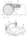
- FIG. 1 ais a perspective underside view of a remote control according to the invention.
- FIG. 1 bis a cross-sectional view of the remote control of FIG. 1 a.
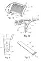
- FIG. 2is a perspective view of a removable strap the remote control of FIGS. 1 a and 1 b is intended to be equipped with.
- FIG. 3is a perspective view of the remote control of FIGS. 1 a and 1 b , equipped with the strap of FIG. 2 .
- FIG. 4is a detailed side view of a locator for the fastening of the strap of FIG. 2 onto the remote control of FIGS. 1 a and 1 b.
- FIG. 5is a cross-sectional view of the remote control of FIGS. 1 a and 1 b , attached to a steering wheel of a motor vehicle by means of the strap of FIG. 2 .
- FIG. 6is a perspective view of an intermediate plate for attaching the remote control of FIGS. 1 a and 1 b to the dashboard of a motor vehicle.
- FIG. 7is a perspective and cross-sectional view of the remote control of FIGS. 1 a and 1 b , mounted on the plate of FIG. 6 .
- FIG. 8is another perspective view of the remote control of FIGS. 1 a and 1 b , mounted on the plate of FIG. 6 .
- FIGS. 1 a and 1 bis shown a remote control 10 intended to control a “hands-free” electronic control unit, not shown, by means of which the driver of a motor vehicle can emit or receive a phone call without having to handle a phone handset.
- control unitalso provides other applications of interest for the user, such as music listening or GPS positioning, for example.
- the remote control 10comprises means adapted to activate, notably through Bluetooth link (Bluethooth is a registered trademark of Bluetooth SIG, Inc.), the remote control of basic functions associated with the applications provided by the electronic control unit, in particular telephony and music listening.
- Bluetooth linkBluetooth is a registered trademark of Bluetooth SIG, Inc.
- buttons 101 , 102 , 103 , 104 , 105for controlling various functions such as: picking up/hanging up a phone call, using the voice recognition, starting or ending music listening, increasing or reducing the sound volume, etc.
- the remote control 10is designed to be attached indifferently to the steering wheel 1 or to the dashboard of the vehicle.
- a cylindrical pad 11 for contact with the steering wheel 1 of the vehicleis arranged on the body of the remote control 10 , as can be seen in FIGS. 1 a and 1 b .
- the cylindrical shape of the pad 11is chosen in order to envelop at best the cross-section of the steering wheel 1 .
- the adherence between the pad 11 and the steering wheel 1may be increased thanks to using elastomer, for example rubber, to make the pad 11 , with the additional advantage of vibration damping.
- corrugations 111 drawn on the pad 11help to further improve the adherence of the pad 11 to the steering wheel 1 .
- a self-gripping strap 20such as that shown in FIGS. 2 , 3 , 4 and 5 is used.
- the strap 20acts as a belt, adapted to maintain the pad 11 stuck against the steering wheel 1 by tightly fitting the remote control 10 around the steering wheel, so that a self-gripping face 201 of the strap 20 is folded over itself around a first insert 12 arranged at a first end of the cylindrical pad 11 , parallel to the generatrices of the latter.
- the strap 20is maintained by a mean 23 for fastening to a second insert 13 arranged at a second end of the cylindrical pad 11 , opposite to the first end, parallel to the first insert 12 .
- the second insertis formed of two end hoods 13
- the fastening means 23is made of a single longitudinal hook extending over the whole width of the strap 20 .
- the second insert 13could also be a single hook extending substantially over the whole width of the pad 11 .
- the inserts 12 , 13are preferably metallic to offer a better rigidity with a minimum thickness, compared to inserts that would be made of plastic material.
- the smooth face 202 of the strap 20in direct contact with the surface of the steering wheel 1 is formed of a material that makes it possible to increase the adherence with the surface of the steering wheel, for example a synthetic leather coating.
- the association of the rubber pad 11 and the strapthus makes possible to limit the force required for tightening the strap, and to have a contact surface that adheres over the almost-totality of the area of contact with the steering wheel.
- the second insertis provided with a locator formed by a rounded edge 131 of the hooks 13 , as shown in the detailed view of FIG. 4 .
- Such plate 30comprises, on the one hand, means for receiving the remote control 10 and, on the other hand, means for attaching to the dashboard.
- the means for receiving the remote control 10comprise a lip 32 for holding the first insert 12 , and locking means consisted of two flexible tabs 33 for clipping by elastic deformation onto the second insert 13 .
- locking meansconsisted of two flexible tabs 33 for clipping by elastic deformation onto the second insert 13 .
- the removal of the remote control 10 from the plate 30is made by the reverse operation, by lifting the remote control so as to force the flexible tabs to open by elastic deformation by means of the second insert and to allow the releasing of the latter.
- the lip 32 of the plate 30is held in position on the remote control 10 thanks to a fitting indentation 34 arranged on the remote control 10 .
- FIG. 6In FIG. 6 are shown ribs 35 for centering the plate 30 on the remote control 10 . These ribs, by respectively resting against the end inserts 13 , ensure a perfect positioning of the plate 30 .
- FIGS. 6 , 7 and 8show the presence on the plate 30 of anti-vibrations bearings 36 intended to come into abutment against the rubber pad 11 , the latter being therefore capable of absorbing the vibrations, which improve the performance of the whole unit.
- the means for fastening the plate 30 on the dashboardmay be adhesive means applied on the contact surface 37 of the plate.
Landscapes
- Engineering & Computer Science (AREA)
- Mechanical Engineering (AREA)
- Fittings On The Vehicle Exterior For Carrying Loads, And Devices For Holding Or Mounting Articles (AREA)
Abstract
Description
- a cylindrical pad for contact with the steering-wheel, arranged on the remote control,
- a first insert extending parallel to the generatrices of the cylindrical pad at a first end of the pad;
- a second insert extending parallel to the generatrices of the cylindrical pad at a second end of the pad, opposite to the first end;
- a removable strap intended to attach the cylindrical contact pad to the steering wheel, the strap comprising a means for fastening to the second insert and a self-gripping face adapted to be folded over itself around the first insert; and
- an removable intermediate plate comprising means for attaching to the vehicle dashboard, means for holding on the first insert and means for locking to the second insert.
Claims (14)
Applications Claiming Priority (3)
| Application Number | Priority Date | Filing Date | Title |
|---|---|---|---|
| FR1150054AFR2969972B1 (en) | 2011-01-04 | 2011-01-04 | SYSTEM FOR FIXING A REMOTE CONTROL OF ELECTRONIC HOUSING IN A MOTOR VEHICLE. |
| FRFR1150054 | 2011-01-04 | ||
| FR1150054 | 2011-01-04 |
Publications (2)
| Publication Number | Publication Date |
|---|---|
| US20120168477A1 US20120168477A1 (en) | 2012-07-05 |
| US8662364B2true US8662364B2 (en) | 2014-03-04 |
Family
ID=44509960
Family Applications (1)
| Application Number | Title | Priority Date | Filing Date |
|---|---|---|---|
| US13/342,869Expired - Fee RelatedUS8662364B2 (en) | 2011-01-04 | 2012-01-03 | System for attaching the remote control of an electronic control unit in a motor vehicle |
Country Status (4)
| Country | Link |
|---|---|
| US (1) | US8662364B2 (en) |
| EP (1) | EP2471690B1 (en) |
| CN (1) | CN102616188B (en) |
| FR (1) | FR2969972B1 (en) |
Cited By (4)
| Publication number | Priority date | Publication date | Assignee | Title |
|---|---|---|---|---|
| US20170253192A1 (en)* | 2016-03-03 | 2017-09-07 | Steering Solutions Ip Holding Corporation | Steering wheel with keyboard |
| US10144383B2 (en) | 2016-09-29 | 2018-12-04 | Steering Solutions Ip Holding Corporation | Steering wheel with video screen and airbag |
| US20200291674A1 (en)* | 2019-03-15 | 2020-09-17 | Deere & Company | Mounting system for mounting an electronic device on a vehicle |
| US20240229503A1 (en)* | 2023-01-06 | 2024-07-11 | Deere & Company | Mounting system for mounting an electronic device on a vehicle |
Families Citing this family (4)
| Publication number | Priority date | Publication date | Assignee | Title |
|---|---|---|---|---|
| CN104627085A (en)* | 2015-02-16 | 2015-05-20 | 北京精灵网络科技有限公司 | Method of fixing vehicular intelligent hardware device |
| CN109398251A (en)* | 2018-11-28 | 2019-03-01 | 深圳市南和移动通信科技股份有限公司 | A kind of pedestal |
| CN111030990B (en)* | 2019-11-05 | 2022-04-12 | 华为技术有限公司 | Method for establishing communication connection, client and server |
| CN217187878U (en)* | 2019-11-15 | 2022-08-16 | 图尔博时尚用品有限责任公司 | Animation device for vehicle and kit for vehicle accessories |
Citations (8)
| Publication number | Priority date | Publication date | Assignee | Title |
|---|---|---|---|---|
| DE19539396A1 (en) | 1994-10-10 | 1996-05-30 | Petru Radu | Motor vehicle electric invalid remote control device for mounting on steering wheel |
| DE29910846U1 (en) | 1999-06-25 | 1999-09-09 | Voit, Stefan, Dipl.-Wirtsch.-Ing., 66386 St Ingbert | Holding element for a remote control element and remote control element |
| US6760569B1 (en) | 2000-01-19 | 2004-07-06 | E-Lead Electronics Co., Ltd. | Foldable peripheral equipment for telecommunication attached to a steering wheel of vehicles |
| US20040204004A1 (en)* | 2002-08-16 | 2004-10-14 | E-Lead Electronic Co., Ltd. | Wireless dialing apparatus for mobile phones |
| EP1502835A1 (en) | 2003-07-24 | 2005-02-02 | Delphi Technologies, Inc. | Method and apparatus for accessing vehicle systems |
| GB2424854A (en) | 2005-04-07 | 2006-10-11 | Bury Sp Zoo | Remote control mounted on a steering wheel |
| US20120286118A1 (en)* | 2011-03-15 | 2012-11-15 | David Richards | Hands-free systems for attaching a personal electronic device and methods for using the same |
| US8348112B2 (en)* | 2008-07-30 | 2013-01-08 | Deere & Company | Mounting system for mounting an electronic device on a vehicle |
Family Cites Families (6)
| Publication number | Priority date | Publication date | Assignee | Title |
|---|---|---|---|---|
| EP1142771A1 (en)* | 2000-04-04 | 2001-10-10 | Mannesmann VDO Aktiengesellschaft | Command module mountable to a member |
| JP2002019552A (en)* | 2000-07-07 | 2002-01-23 | Kenwood Corp | Remote controller and installing structure therefor |
| DE20319315U1 (en)* | 2003-12-12 | 2004-02-26 | Siemens Ag | Object to be joined to round element like steering wheel, comprising fixing strap with lock to be moved transversally and longitudinally |
| CN2852552Y (en)* | 2005-10-27 | 2006-12-27 | 精元电脑股份有限公司 | Bluetooth wireless dialing device for car steering wheel |
| CN201249710Y (en)* | 2008-07-25 | 2009-06-03 | 深圳市豪恩电子科技股份有限公司 | Fixing device of automobile steering wheel auxiliary device |
| CN101930661B (en)* | 2009-06-26 | 2012-08-22 | 宏达国际电子股份有限公司 | Remote control device and remote control method of electronic device |
- 2011
- 2011-01-04FRFR1150054Apatent/FR2969972B1/ennot_activeExpired - Fee Related
- 2011-12-30CNCN201110463366.9Apatent/CN102616188B/ennot_activeExpired - Fee Related
- 2012
- 2012-01-03EPEP12150034.2Apatent/EP2471690B1/ennot_activeNot-in-force
- 2012-01-03USUS13/342,869patent/US8662364B2/ennot_activeExpired - Fee Related
Patent Citations (9)
| Publication number | Priority date | Publication date | Assignee | Title |
|---|---|---|---|---|
| DE19539396A1 (en) | 1994-10-10 | 1996-05-30 | Petru Radu | Motor vehicle electric invalid remote control device for mounting on steering wheel |
| DE29910846U1 (en) | 1999-06-25 | 1999-09-09 | Voit, Stefan, Dipl.-Wirtsch.-Ing., 66386 St Ingbert | Holding element for a remote control element and remote control element |
| US6760569B1 (en) | 2000-01-19 | 2004-07-06 | E-Lead Electronics Co., Ltd. | Foldable peripheral equipment for telecommunication attached to a steering wheel of vehicles |
| US20040204004A1 (en)* | 2002-08-16 | 2004-10-14 | E-Lead Electronic Co., Ltd. | Wireless dialing apparatus for mobile phones |
| EP1502835A1 (en) | 2003-07-24 | 2005-02-02 | Delphi Technologies, Inc. | Method and apparatus for accessing vehicle systems |
| GB2424854A (en) | 2005-04-07 | 2006-10-11 | Bury Sp Zoo | Remote control mounted on a steering wheel |
| US7456777B2 (en)* | 2005-04-07 | 2008-11-25 | Bury Sp.Z.O.O. | Remote control means |
| US8348112B2 (en)* | 2008-07-30 | 2013-01-08 | Deere & Company | Mounting system for mounting an electronic device on a vehicle |
| US20120286118A1 (en)* | 2011-03-15 | 2012-11-15 | David Richards | Hands-free systems for attaching a personal electronic device and methods for using the same |
Cited By (6)
| Publication number | Priority date | Publication date | Assignee | Title |
|---|---|---|---|---|
| US20170253192A1 (en)* | 2016-03-03 | 2017-09-07 | Steering Solutions Ip Holding Corporation | Steering wheel with keyboard |
| US10322682B2 (en)* | 2016-03-03 | 2019-06-18 | Steering Solutions Ip Holding Corporation | Steering wheel with keyboard |
| US10144383B2 (en) | 2016-09-29 | 2018-12-04 | Steering Solutions Ip Holding Corporation | Steering wheel with video screen and airbag |
| US20200291674A1 (en)* | 2019-03-15 | 2020-09-17 | Deere & Company | Mounting system for mounting an electronic device on a vehicle |
| US12000171B2 (en)* | 2019-03-15 | 2024-06-04 | Deere & Company | Mounting system for mounting an electronic device on a vehicle |
| US20240229503A1 (en)* | 2023-01-06 | 2024-07-11 | Deere & Company | Mounting system for mounting an electronic device on a vehicle |
Also Published As
| Publication number | Publication date |
|---|---|
| FR2969972B1 (en) | 2013-02-08 |
| EP2471690B1 (en) | 2014-03-19 |
| FR2969972A1 (en) | 2012-07-06 |
| EP2471690A1 (en) | 2012-07-04 |
| CN102616188A (en) | 2012-08-01 |
| US20120168477A1 (en) | 2012-07-05 |
| CN102616188B (en) | 2015-07-15 |
Similar Documents
| Publication | Publication Date | Title |
|---|---|---|
| US8662364B2 (en) | System for attaching the remote control of an electronic control unit in a motor vehicle | |
| US8646825B2 (en) | Overhead console with storage unit insert | |
| US20090108152A1 (en) | Suction cup mounting platform | |
| US20110132950A1 (en) | Seat Belt Attachment | |
| WO2007069057A3 (en) | Mounting device for a fastening system of trim elements to vehicle body | |
| JP2011523829A (en) | Device for supporting portable electronic device having fixing device provided with magnetic support member | |
| WO2001095665A1 (en) | Speaker installation structure | |
| US6959948B2 (en) | Gimp with a concealed slip zone | |
| US8157313B2 (en) | Storage unit with electronic device mounting structure | |
| EP1882612A3 (en) | Interior trim fastener system | |
| US20090127882A1 (en) | Trapping device for vehicle use | |
| US20100170926A1 (en) | Safety arrangement for bicycle apparatus carrier | |
| WO2006126818A1 (en) | Fixed cellular phone for vehicle | |
| GB2493426B (en) | Trim element for a motor vehicle interior | |
| US20160368428A1 (en) | Bag holding bracket | |
| JP5134492B2 (en) | Microphone mounting device | |
| JP3137244U (en) | Vehicle pedal cover | |
| JP2009280125A (en) | Sealing structure of in-vehicle speaker | |
| CN110726009B (en) | Pipeline clamping structure and vehicle pipeline assembly | |
| KR200484345Y1 (en) | Cradle for smart device | |
| CN114382759B (en) | Durable shoe-shaped clamping fastener for vehicle decorative accessories | |
| JP2013023097A (en) | Carrier in vehicle | |
| EP3522507B1 (en) | Holding device for a mobile device | |
| KR20240129870A (en) | a cell phone case for a vehicle | |
| US7338103B2 (en) | Collapsible cover for vehicle interior |
Legal Events
| Date | Code | Title | Description |
|---|---|---|---|
| AS | Assignment | Owner name:PARROT, FRANCE Free format text:ASSIGNMENT OF ASSIGNORS INTEREST;ASSIGNOR:VUILLET, JEAN FRANCOIS;REEL/FRAME:027837/0986 Effective date:20120302 | |
| STCF | Information on status: patent grant | Free format text:PATENTED CASE | |
| AS | Assignment | Owner name:PARROT DRONES, FRANCE Free format text:ASSIGNMENT OF ASSIGNORS INTEREST;ASSIGNOR:PARROT;REEL/FRAME:039323/0421 Effective date:20160329 | |
| MAFP | Maintenance fee payment | Free format text:PAYMENT OF MAINTENANCE FEE, 4TH YEAR, LARGE ENTITY (ORIGINAL EVENT CODE: M1551) Year of fee payment:4 | |
| FEPP | Fee payment procedure | Free format text:MAINTENANCE FEE REMINDER MAILED (ORIGINAL EVENT CODE: REM.); ENTITY STATUS OF PATENT OWNER: LARGE ENTITY | |
| LAPS | Lapse for failure to pay maintenance fees | Free format text:PATENT EXPIRED FOR FAILURE TO PAY MAINTENANCE FEES (ORIGINAL EVENT CODE: EXP.); ENTITY STATUS OF PATENT OWNER: LARGE ENTITY | |
| STCH | Information on status: patent discontinuation | Free format text:PATENT EXPIRED DUE TO NONPAYMENT OF MAINTENANCE FEES UNDER 37 CFR 1.362 | |
| FP | Lapsed due to failure to pay maintenance fee | Effective date:20220304 |