US8662182B2 - Methods and apparatus for subsea well intervention and subsea wellhead retrieval - Google Patents
Methods and apparatus for subsea well intervention and subsea wellhead retrievalDownload PDFInfo
- Publication number
- US8662182B2 US8662182B2US13/649,927US201213649927AUS8662182B2US 8662182 B2US8662182 B2US 8662182B2US 201213649927 AUS201213649927 AUS 201213649927AUS 8662182 B2US8662182 B2US 8662182B2
- Authority
- US
- United States
- Prior art keywords
- tool
- wellhead
- subsea
- casing string
- subsea wellhead
- Prior art date
- Legal status (The legal status is an assumption and is not a legal conclusion. Google has not performed a legal analysis and makes no representation as to the accuracy of the status listed.)
- Active
Links
Images


Classifications
- E—FIXED CONSTRUCTIONS
- E21—EARTH OR ROCK DRILLING; MINING
- E21B—EARTH OR ROCK DRILLING; OBTAINING OIL, GAS, WATER, SOLUBLE OR MELTABLE MATERIALS OR A SLURRY OF MINERALS FROM WELLS
- E21B23/00—Apparatus for displacing, setting, locking, releasing or removing tools, packers or the like in boreholes or wells
- E—FIXED CONSTRUCTIONS
- E21—EARTH OR ROCK DRILLING; MINING
- E21B—EARTH OR ROCK DRILLING; OBTAINING OIL, GAS, WATER, SOLUBLE OR MELTABLE MATERIALS OR A SLURRY OF MINERALS FROM WELLS
- E21B29/00—Cutting or destroying pipes, packers, plugs or wire lines, located in boreholes or wells, e.g. cutting of damaged pipes, of windows; Deforming of pipes in boreholes or wells; Reconditioning of well casings while in the ground
- E21B29/002—Cutting, e.g. milling, a pipe with a cutter rotating along the circumference of the pipe
- E21B29/005—Cutting, e.g. milling, a pipe with a cutter rotating along the circumference of the pipe with a radially-expansible cutter rotating inside the pipe, e.g. for cutting an annular window
- E—FIXED CONSTRUCTIONS
- E21—EARTH OR ROCK DRILLING; MINING
- E21B—EARTH OR ROCK DRILLING; OBTAINING OIL, GAS, WATER, SOLUBLE OR MELTABLE MATERIALS OR A SLURRY OF MINERALS FROM WELLS
- E21B29/00—Cutting or destroying pipes, packers, plugs or wire lines, located in boreholes or wells, e.g. cutting of damaged pipes, of windows; Deforming of pipes in boreholes or wells; Reconditioning of well casings while in the ground
- E21B29/12—Cutting or destroying pipes, packers, plugs or wire lines, located in boreholes or wells, e.g. cutting of damaged pipes, of windows; Deforming of pipes in boreholes or wells; Reconditioning of well casings while in the ground specially adapted for underwater installations
- E—FIXED CONSTRUCTIONS
- E21—EARTH OR ROCK DRILLING; MINING
- E21B—EARTH OR ROCK DRILLING; OBTAINING OIL, GAS, WATER, SOLUBLE OR MELTABLE MATERIALS OR A SLURRY OF MINERALS FROM WELLS
- E21B33/00—Sealing or packing boreholes or wells
- E21B33/02—Surface sealing or packing
- E21B33/03—Well heads; Setting-up thereof
- E21B33/035—Well heads; Setting-up thereof specially adapted for underwater installations
- E—FIXED CONSTRUCTIONS
- E21—EARTH OR ROCK DRILLING; MINING
- E21B—EARTH OR ROCK DRILLING; OBTAINING OIL, GAS, WATER, SOLUBLE OR MELTABLE MATERIALS OR A SLURRY OF MINERALS FROM WELLS
- E21B47/00—Survey of boreholes or wells
- E21B47/001—Survey of boreholes or wells for underwater installation
- B—PERFORMING OPERATIONS; TRANSPORTING
- B24—GRINDING; POLISHING
- B24C—ABRASIVE OR RELATED BLASTING WITH PARTICULATE MATERIAL
- B24C1/00—Methods for use of abrasive blasting for producing particular effects; Use of auxiliary equipment in connection with such methods
- B24C1/04—Methods for use of abrasive blasting for producing particular effects; Use of auxiliary equipment in connection with such methods for treating only selected parts of a surface, e.g. for carving stone or glass
- B24C1/045—Methods for use of abrasive blasting for producing particular effects; Use of auxiliary equipment in connection with such methods for treating only selected parts of a surface, e.g. for carving stone or glass for cutting
- B—PERFORMING OPERATIONS; TRANSPORTING
- B24—GRINDING; POLISHING
- B24C—ABRASIVE OR RELATED BLASTING WITH PARTICULATE MATERIAL
- B24C3/00—Abrasive blasting machines or devices; Plants
- B24C3/32—Abrasive blasting machines or devices; Plants designed for abrasive blasting of particular work, e.g. the internal surfaces of cylinder blocks
- B24C3/325—Abrasive blasting machines or devices; Plants designed for abrasive blasting of particular work, e.g. the internal surfaces of cylinder blocks for internal surfaces, e.g. of tubes
Definitions
- Embodiments of the present inventiongenerally relate to a subsea well. More particularly, embodiments of the invention relate to methods and apparatus for subsea well intervention operations, including retrieval of a wellhead from a subsea well.
- the subsea well closing processtypically includes recovering the wellhead from the subsea well using a conventional wellhead retrieval operation.
- a retrieval assembly equipped with a casing cutteris lowered on a work string from a floating rig until the retrieval assembly is positioned over the subsea wellhead.
- the casing cutteris lowered into the wellbore as the retrieval assembly is lowered onto the wellhead.
- the casing cutteris actuated to cut the casing by using the work string.
- the cuttermay be powered by rotating the work string from the floating rig.
- the floating rigSince the work string is used to manipulate the retrieval assembly and the casing cutter, the floating rig is required at the surface to provide the necessary support and structure for the work string. Even though the subsea wellhead may be removed in this manner, the use of the floating rig and the work string can be costly and time consuming. Therefore, there is a need for an improved method and apparatus for subsea wellhead retrieval.
- the present inventiongenerally relates to methods and apparatus for subsea well intervention operations, including retrieval of a wellhead from a subsea well.
- a method of performing an operation in a subsea wellcomprises the step of positioning a tool proximate a subsea wellhead.
- the toolhas at least one grip member and the tool is attached to a downhole assembly.
- the methodalso comprises the step of clamping the tool to the subsea wellhead by moving the at least one grip member into engagement with a profile on the subsea wellhead.
- the methodfurther comprises the step of applying an upward force to the tool thereby enhancing the grip between the grip member and the profile on the subsea wellhead.
- the methodcomprises the step of performing the operation in the subsea well by utilizing the down hole assembly.
- an apparatus for use in a subsea wellcomprises a grip member movable between an unclamped position and a clamped position, wherein the grip member in the clamped position applies a grip force to a profile on the subsea wellhead. Additionally, the apparatus comprises a lifting assembly configured to generate an upward force which increases the grip force applied by the grip member.
- a method of performing an operation in a subsea wellcomprises the step of positioning a tool proximate a subsea wellhead.
- the toolhas at least one grip member and a lock member.
- the toolis also attached to a downhole assembly.
- the methodfurther comprises the step of moving the at least one grip member from an unclamped position to a clamped position in which the grip member engages the subsea wellhead.
- the methodalso comprises the step of hydraulically activating the lock member such that the lock member engages a portion of the grip member thereby retaining the grip member in the clamped position.
- the methodcomprises the step of performing the operation in the subsea well by utilizing the downhole assembly.
- an apparatus for use in a subsea wellcomprises a grip member for engaging a subsea wellhead, wherein the grip member is movable between an unclamped position and a clamped position.
- the apparatusfurther comprises a lock member movable between an unlocked position and a locked position upon activation of a hydraulic cylinder, wherein the lock member in the locked position retains the grip member in the clamped position.
- a method of cutting a casing string in a subsea wellcomprises the step of positioning a tool proximate a subsea wellhead.
- the toolhas at least one grip member and the tool is attached to a cutting assembly.
- the methodfurther comprises the step of operating the at least one grip member to clamp the tool to the subsea wellhead.
- the methodalso comprises the step of cutting the casing string below the subsea wellhead by utilizing the cutting assembly.
- the methodcomprises the step of applying an upward force to the tool during the cutting of the casing string which is at least equal to an axial reaction force generated from cutting the casing string, wherein at least a portion of the upward force is created by a cylinder member in the tool that acts on the subsea wellhead.
- an apparatus for cutting a casing string in a subsea wellcomprises a cutting assembly configured to cut the casing string.
- the apparatusalso comprises a grip member for engaging a subsea wellhead, the grip member movable between an unclamped position and a clamped position.
- the apparatuscomprises a lifting assembly configured to generate an upward force which is at least equal to an axial reaction force generated from cutting the casing string, wherein the lifting assembly comprises a cylinder and piston arrangement that is configured to act upon a portion of the subsea wellhead.
- a method of gripping a subsea wellheadcomprises the step of positioning a tool proximate the subsea wellhead.
- the toolhas at least one grip member.
- the methodfurther comprises the step of clamping the tool to the subsea wellhead by moving the at least one grip member into engagement with a profile on the subsea wellhead.
- the methodcomprises the step of applying an upward force to the tool thereby enhancing the grip between the grip member and the profile on the subsea wellhead.
- FIG. 1is an isometric view of a subsea wellhead intervention and retrieval tool according to one embodiment of the invention.
- FIG. 2is a view illustrating the placement of the tool on a wellhead.
- FIG. 3is a view illustrating the tool engaging the wellhead.
- FIG. 4is a view illustrating the tool cutting a casing string below the wellhead.
- FIGS. 5A and 5Bare enlarged views illustrating the components of the tool.
- FIG. 6is a view illustrating the tool after the casing string has been cut.
- FIG. 7is a view illustrating a subsea wellhead intervention and retrieval tool with a perforating tool.
- FIG. 8is a view illustrating a subsea wellhead intervention and retrieval tool with the perforating tool disposed on a wireline.
- FIG. 9is a view illustrating a subsea wellhead intervention and retrieval tool with the perforating tool.
- FIG. 10is a view illustrating a subsea wellhead intervention and retrieval tool with a cutter assembly.
- FIG. 11is a view illustrating a subsea wellhead intervention and retrieval tool with an explosive charge device.
- Embodiments of the present inventiongenerally relate to methods and apparatus for subsea well intervention operations, including retrieval of a wellhead from a subsea well. To better understand the aspects of the present invention and the methods of use thereof, reference is hereafter made to the accompanying drawings.
- FIG. 1shows a subsea wellhead intervention and retrieval tool 100 according to one embodiment of the invention.
- the tool 100includes a shackle 210 and a mandrel 195 for connection to a conveyance member 202 , such as a cable.
- a conveyance member 202such as a cable.
- the use of cable with the tool 100allows for greater flexibility because the cable may be deployed from an offshore location that includes a crane rather than using a floating rig with a work string as in the conventional wellhead retrieval operation.
- the conveyance membermay be an umbilical, coil tubing, wireline or jointed pipe.
- the conveyance member 202is used to lower the tool 100 into the sea to a position adjacent the subsea wellhead.
- a power source(not shown), such as a hydraulic pump, pneumatic pump or a electrical control source, is attached to the tool 100 via an umbilical cord (not shown) connected to connectors 205 to manipulate and/or monitor the operation of the tool 100 .
- the power sourceis attached to a control system 230 of the tool 100 .
- the control system 230may include a manifold arrangement that integrates one or more cylinders of the tool 100 .
- the manifold arrangementmay include a filtration system and a plurality of pilot operated check valves which allows the cylinders of the tool to function in a forward direction or a reverse direction.
- the manifold arrangementallows the cylinders to operate independently from the other components in the tool 100 .
- the functionality of the cylinderswill be discussed herein.
- the control system 230may also include data sensors, such as pressure sensors and temperature sensors that generate data regarding the components of the tool 100 .
- the datamay be used to monitor the operation of the tool 100 and/or control the components of the tool 100 . Further, the data may be used locally by an onboard computer or by the ROV. The data may also be used remotely by sending the data back to the surface via the ROV or via an umbilical attached to the tool.
- the power source for controlling the control system 230 of the tool 100is typically located near the surface.
- the power sourcemay be configured to pump fluid from the offshore location through the umbilical cord connected to the connectors 205 in order to operate the components of the tool 100 such as arms 125 and wedge blocks 150 as described herein.
- the tool 100may be manipulated using a remotely operated underwater vehicle (ROV).
- ROVremotely operated underwater vehicle
- the ROVmay attach to the tool 100 via a stab connector 215 and then control the control system 230 of the tool 100 in a similar manner as described herein.
- the ROVmay also manipulate the position of the tool 100 relative to the wellhead by using handler members 220 .
- the tool 100may be attached to a downhole assembly such as a motor 115 and a rotary cutter assembly 105 .
- the motor 115may be an electric motor or a hydraulic motor such as a mud motor.
- the rotary cutter assembly 105includes a plurality of blades 110 which are used to cut the casing.
- the blades 110are movable between a retracted position and an extended position.
- the tool 100may use an abrasive cutting device to cut the casing instead of the rotary cutter assembly 105 .
- the abrasive cutting devicemay include a high pressure nozzle configured to output high pressure fluid to cut the casing.
- abrasive cutting technologyallows the tool 100 to cut through the casing with substantially no downward pull or torque transmission to the wellhead which is common with the rotary cutter assembly 105 .
- the tool 100may use a high energy source such as laser, high power light, or plasma to cut the casing.
- the high energy cutting systemmay be incorporated into the tool 100 or conveyed to or through the tool 100 via a transmission system.
- Suitable cutting systemsmay use well fluids, and/or water to cut through multiple casings, cement and voids. The cutting systems may also reduce downward pull and subsequent reactive torque transmission to the wellhead.
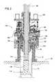
- FIG. 2is a view illustrating the placement of the tool 100 on a wellhead 10 .
- the tool 100is lowered via the conveyance member until the tool 100 is positioned proximate the top of the wellhead 10 disposed on a seafloor 20 .
- the motor 115 and the cutter assembly 105are lowered into the wellhead 10 such that the blades 110 of the cutter assembly 105 are adjacent the casing string 30 attached to the wellhead 10 .
- the wellhead 10includes a profile 50 at an upper end.
- the profile 50may have different configurations depending on which company manufactured the wellhead 10 .
- the arms 125 of the tool 100include a matching profile 165 to engage the wellhead 10 during the wellhead retrieval operation.
- the arms 125 or the profile 165 on the arms 125may be changed (e.g., removed and replaced) with a different profile in order to match the specific profile on the wellhead 10 of interest.
- the arms 125are shown in an unclamped position in FIG. 2 and in a clamped position in FIG. 3 .
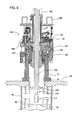
- FIG. 3illustrates the tool 100 engaging the wellhead 10 .
- the tool 100includes an actuating cylinder 135 (e.g. piston and cylinder arrangement) that is attached to the arm 125 .
- the arms 125rotate around pivot 130 from the unclamped position to the clamped position in order to engage the wellhead 10 .
- the arms 125may be individually activated by a respective cylinder 135 or collectively activated by one or more cylinders.
- the profile 165 on the arms 125mate with the corresponding profile 50 on the wellhead 10 .
- the arms 125are locked in place by activating a locking cylinder 155 (e.g.
- wedge block 150which causes a wedge block 150 to slide along a surface of the arm 125 as shown in FIG. 4 .
- the movement of the wedge block 150prevents the arms 125 from rotating around the pivot 130 to the clamped position.
- the wedge blocks 150may be individually activated by the respective cylinder 155 or collectively activated by one or more cylinders.
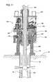
- FIG. 4is a view illustrating the tool 100 cutting a casing string 30 below the wellhead 10 .
- an optional cylinder 180e.g. piston and cylinder arrangement
- a shoe 175to act upon a surface 25 of the wellhead 10 and axially lift the tool 100 relative to the wellhead 10 .
- the axial movement of the tool 100 relative to the wellhead 10allows for active clamping of the tool 100 on the wellhead 10 .
- the profile 165 on the arms 125moves into maximum contact with the profile 50 on the wellhead 10 such that the tool 100 is clamped on the wellhead 10 and will not rotate (or spin) relative to the wellhead 10 when the rotary cutter assembly 105 is in operation.
- reactive torque resistanceis provided for the mechanical cutting system.
- cylinders 135 , 155 , 180may be independently operated by the power source or by the ROV. Additionally, it is contemplated that cylinders 135 , 155 , 180 may include any suitable number of cylinders as necessary to perform the intended function.
- FIGS. 5A and 5Bare enlarged views illustrating the components of the tool 100 .
- the conveyance membermay be pulled from the surface to enhance the clamping of the tool 100 on the wellhead 10 .
- the upward force applied to the tool 100 by the conveyance membercauses an inner mandrel 170 to move from a first position ( FIG. 5A ) to a second position ( FIG. 5B ).
- the inner mandrel 170includes a key member 190 .
- the key member 190may be a separate component attached to the inner mandrel 170 as illustrated or the key member 190 may be formed as part of the mandrel 170 as a single piece. As shown in FIG.
- the inner mandrel 170has moved axially up relative to the wellhead 10 .
- the inner mandrel 170(and/or the key member 190 ) contacts and applies a force to a surface 120 of the arms 125 which increases (or enhances) the gripping force applied by the arms 125 to the profile 50 on the wellhead 10 .
- the inner mandrel 170applies the force to the arms 125 and that force is transferred due to the shape of each arm 125 (i.e. lever) and the pivot 130 into the gripping surface which grips the profile 50 , thereby enhancing the grip on the profile 50 .
- the conveyance member connected to the tool 100may also be pulled from the surface (i.e., offshore location) to create tension in the wellhead 10 and the casing string 30 .
- the tool 100 , the wellhead 10 , and the casing string 30are urged upward relative to the seafloor 20 which creates tension in the wellhead 10 and the casing string 30 .
- the tension created by pulling on the conveyance membermay be useful during the cutting operation because tension in the casing string 30 typically prevents the cutters 110 of the rotary cutter assembly 105 from jamming (or become stuck) as the cutters 110 cut through the casing string 30 .
- the upward force created by pulling on the conveyance memberis preferably at least equal to any downward force generated during the cutting operation.
- the upward forceis typically maintained during the cutting operation.
- the upward forcemay also be sufficient to counteract the wellhead assembly deadweight.
- the inner mandrel 170 in the tool 100may move between the first position as shown in FIG. 5A and the second position as shown in FIG. 5B .
- a portion of the inner mandrel 170 (and/or the key member 190 )is positioned proximate a stop block 185 as shown in FIG. 5A .
- the inner mandrel 170has moved axially down relative to the wellhead 10 which typically occurs when the tension in the conveyance member attached to the tool 100 has been minimized.
- the second positiona portion of the inner mandrel 170 is positioned proximate the surface 120 of the arms 125 .
- the inner mandrel 170has moved axially up relative to the wellhead 10 which typically occurs when the tension in the conveyance member attached to the tool 100 has been increased. Further, in the second position, the inner mandrel 170 (and/or the key member 190 ) contacts and applies a force to the surface 120 of the arms 125 which increases (or enhances) the gripping force applied by the arms 125 to the profile 50 on the wellhead 10 . In other words, the inner mandrel 170 applies the force to the arms 125 and that force is transferred due to the shape of each arm 125 (i.e. lever) and the pivot 130 into the gripping surface which grips the profile 50 , thereby enhancing the grip on the profile 50 .
- FIG. 6is a view illustrating the tool 100 after the casing string 30 has been cut.
- the cutters 110 on the rotary cutter assembly 105continue to operate until a lower portion of the casing string 30 is disconnected from an upper portion of the casing string 30 .
- the rotary cutter assembly 105is deactivated which causes the cutters 110 to move from the extended position to the retracted position.
- the tool 100 , the wellhead 10 , and a portion of the casing string 30are lifted from the seafloor 20 by pulling on the conveyance member attached to the tool 100 until the wellhead 10 is removed from the sea.
- the cylinders 135 , 155 , 180may be systematically deactivated to release the tool 100 from the wellhead 10 .
- the tool 100is lowered into the sea via the conveyance member until the tool 100 is positioned proximate the top of the wellhead 10 disposed on the seafloor 20 .
- the cylinder 135is actuated to cause the arms 125 to rotate around pivot 130 to engage the wellhead 10 .
- the arms 125are locked in place by actuating the cylinder 155 which causes the wedge block 150 to slide along the surface of the arms 125 to prevent the arms 125 from rotating around the pivot 130 to the unclamped position.
- the cylinder 180is activated which causes the shoe 175 to act upon the surface 25 of the wellhead 10 and axially lift the tool 100 relative to the wellhead 10 .
- the axial movement of the tool 100 relative to the wellhead 10allows for active clamping of the tool 100 on the wellhead 10 .
- This sequential functionis automatically controlled by the onboard manifold or can be manually sequenced as required by the operator or via a ROV.
- the conveyance member connected to the tool 100is pulled from the surface (i.e. offshore location) to create tension on the wellhead assembly 10 and the casing string 30 .
- the motor 115activates the rotary cutter assembly 105 and the blades 110 move from the retracted position to the extended position to cut through the casing string or multiple casing strings 30 .
- the wellhead assembly deadweightis born mechanically to leverage the load for increased clamping force on the external wellhead profile to maximize reactive torque resistance capability for high torque cutting.
- Axial load cylinder 180function to stabilize and preload grip arms during cutting operation. After the casing string 30 is cut, the tool 100 , the wellhead 10 and a portion of the casing string 30 is lifted from the seafloor 20 by pulling on the conveyance member attached to the tool 100 .
- the cylinders 135 , 155 , 180may be systematically deactivated to release the tool 100 from the wellhead 10 .
- the cylinder function sets 135 , 155 , 180may be independently controlled and shut down or reversed for function testing, unsuccessful wellhead release, or maintenance as required through surface controls or remotely using a ROV in case of umbilical failure.
- FIG. 7is a view illustrating a subsea wellhead intervention and retrieval tool 200 attached to a perforating tool 215 .
- the components of the tool 200 that are similar to the components of the tool 100will be labeled with the same reference indicator.
- the tool 200has engaged the wellhead 10 in a similar manner as described herein.
- the tool 200may be attached to an optional packer member 205 that is configured to seal an annulus formed between a tubular member 220 and the casing string 30 attached to the wellhead 10 .
- the packer member 205may be any type of packer known in art, such as a hydraulic packer or a mechanical packer.
- the packer member 205may be used for isolation or well control. Upon activation of the packer member 205 , the packer member 205 moves from a first diameter and a second larger diameter. Upon deactivation, the packer member 205 moves from the second larger diameter to the first diameter.
- the packer member 205may be activated and deactivated multiple times.
- the tool 200may be attached to an optional ported sub 210 and the perforating tool 215 mounted on a pipe 225 .
- the pipe 225 , the ported sub 210 and the perforating tool 215may be an integral part of the tool 200 or a separate component that is lowered through the tool 200 via a conveyance member, such as pipe, coiled tubing or an umbilical.
- the ported sub 210may be used in conjunction with the packer member 205 to monitor, control pressure or bleed-off pressure, gas or liquid.
- the ported sub 210may also be used to pump cement into the wellbore.
- the ported sub 210is selectively movable between an open position and a closed position multiple times.
- the perforating tool 215is generally a device used to perforate (or punch) the casing string 30 or multiple casing strings, such as casing strings 30 , 40 .
- the perforating tool 215includes several shaped explosive charges that are selectively activated to perforate the casing string. It is to be noted that the perforating tool 215 may also be used to sever or cut the casing string 30 so that the wellhead 10 may be removed in a similar manner as described herein.
- the tool 200is lowered into the sea via the conveyance member and attached to the wellhead 10 disposed on the seafloor 20 in a similar manner as set forth herein.
- the optional packer 205may be activated.
- the ported sub 210may also be activated and used as set forth herein.
- the perforating tool 215may be used to perforate (or cut) the casing string.
- the tool 200may further be used to remove the wellhead 10 in a similar manner as described herein.
- FIG. 8is a view illustrating a subsea wellhead intervention and retrieval tool 250 with the perforating tool 215 disposed on a wireline 255 .
- the components of the tool 250that are similar to the components of the tools 100 , 200 will be labeled with the same reference indicator.
- the tool 250has engaged the wellhead 10 in a similar manner as described herein.
- the perforating tool 215has been positioned in the casing string 30 by utilizing the wireline 255 . This arrangement may be useful if multiple areas are to be perforated by the perforating tool 215 .
- wireline 255allows the capability of running the perforating tool 215 in and out of the wellbore multiple times (or runs). Additionally, the tubular member 220 is open ended thereby allowing fluid flow to be pumped through the tubular member 220 .
- the tool 250is lowered into the sea via the conveyance member and attached to the wellhead 10 disposed on the seafloor 20 in a similar manner as set forth herein.
- the optional packer 205may be activated to create a seal between the tubular member 220 and the casing string 30 .
- the perforating tool 215may be positioned in the casing string 30 by utilizing the wireline 255 and then activated to perforate (or cut) the casing string.
- the tool 250may further be used to remove the wellhead 10 in a similar manner as described herein.
- FIG. 9is a view illustrating a subsea wellhead intervention and retrieval tool 300 with the perforating tool 215 .
- the components of the tool 300that are similar to the components of tools 100 , 200 will be labeled with the same reference indicator.
- the tool 300has engaged the wellhead 10 in a similar manner as described herein.
- the tool 300includes the ported sub 210 and the perforating tool 215 .
- the perforating tool 215may be used to perforate (or sever) the casing string 30 or any number of casing strings, such as casing strings 30 , 60 .
- the ported sub 210may be used in a pressure test and/or to distribute cement 55 which is pumped from the surface.
- the tool 300is lowered into the sea via the conveyance member and attached to the wellhead 10 disposed on the seafloor 20 in a similar manner as set forth herein.
- the optional packer 205may be activated and the ported sub 210 may used as set forth herein.
- the perforating tool 215may be operated to perforate (or cut) the casing string.
- the tool 300may further be used to remove the wellhead 10 in a similar manner as described herein.
- FIG. 10is a view illustrating a subsea wellhead intervention and retrieval tool 350 attached to a cutter assembly 360 .
- the components of the tool 350 that are similar to the components of the tool 100will be labeled with the same reference indicator.
- the tool 350has engaged the wellhead 10 in a similar manner as described herein.
- the cutter assembly 360uses a cutting stream 365 to cut the casing string 30 .
- the cutter assembly 360is a laser cutter.
- the laser cutterwould be connected to the surface via a fiber optic bundle (not shown).
- the fiber optic bundlewould be used to transmit light energy to the cutter assembly 360 from lasers on the surface.
- the cutter assembly 360would direct the light energy by using a series of lenses (not shown) in the cutter assembly 360 toward the casing string 30 .
- the light energyi.e. cutting stream 365
- the cutter assembly 360is a plasma cutter.
- the plasma cutterwould be connected to the surface via a conduit line (not shown).
- the conduit linewould be used to transmit pressurized gas to the cutter assembly 360 .
- the gasis blown out of a nozzle in the cutter assembly 360 at a high speed, at the same time an electrical arc is formed through that gas from the nozzle to the surface being cut, turning some of that gas to plasma.
- the plasmais sufficiently hot to melt the metal of the casing string 30 .
- the plasmai.e. cutting stream 365 ) would be used to cut the casing string 30 or perforate a hole in the casing string 30 .
- the cutter assembly 360is an abrasive cutter.
- the abrasive cutterwould be connected to the surface via a fluid conduit (not shown).
- the fluid conduitwould be used to transmit pressurized fluid having abrasives to the cutter assembly 360 .
- the pressurized fluid(with abrasives) is blown out of a nozzle in the cutter assembly 360 .
- the pressurized fluidi.e. cutting stream 365 ) would be used to cut the casing string 30 or perforate a hole in the casing string 30 .
- a chemical or a high energy mediamay be used with the cutter assembly 360 to cut (or perforate) the casing string 30 .
- the tool 350includes an optional rotating device 355 configured to rotate the cutter assembly 360 .
- the rotating device 355may be controlled at the surface or downhole.
- the rotating device 355may be powered by electric power or hydraulic power.
- the rotating device 355will rotate the cutter assembly 360 in a 360 degree rotation in order to cut the casing string 30 .
- the speed, direction and the timing of the rotationwill also be controlled by the rotating device 355 in order to allow the cutting stream 365 to sever (or perforate) the casing string 30 .
- the tool 350may be attached to an optional anchor device 370 to anchor the tool 350 to the casing string 30 .
- the anchor device 370may include radially extendable members that grip the casing string 30 upon activation of the anchor device 370 .
- the anchor device 370is used to stabilize (or centralize) the cutter assembly 360 in the casing string 30 .
- the tool 350is lowered into the sea via the conveyance member and attached to the wellhead 10 disposed on the seafloor 20 in a similar manner as set forth herein.
- the optional anchoring device 370may be used to stabilize (or centralize) the cutter assembly 360 in the casing string 30 .
- the cutter assembly 360may be activated to perforate (or cut) the casing string and the cutter assembly may be rotated by using the rotating device 355 .
- the tool 350may further be used to remove the wellhead 10 in a similar manner as described herein.
- FIG. 11is a view illustrating a subsea wellhead intervention and retrieval tool 400 with an explosive charge device 405 .
- the components of the tool 400 that are similar to the components of tools 100 , 200will be labeled with the same reference indicator.
- the tool 400has engaged the wellhead 10 in a similar manner as described herein.
- the tool 400includes the explosive charge device 405 for cutting (or perforating) the casing string 30 or any number of casing strings.
- the explosive charge device 405includes several shaped explosive charges that are selectively activated to cut (or perforate) the casing string 30 .
- the explosive charge device 405may also include a single massive explosive charge. If the casing string 30 is to be cut, the explosive charge device 405 may include a 360 degree charge which will cut (or sever) the casing string 30 upon activation. In the embodiment illustrated in FIG. 11 , the explosive charge device 405 is part of the tool 400 . It is to be noted, however, that the explosive charge device 405 could be a separate device that is lowered through the tool 405 via a wireline or another type of conveyance member, such as coil tubing, jointed pipe or an umbilical.
- the tool 400is lowered into the sea via the conveyance member and attached to the wellhead 10 disposed on the seafloor 20 in a similar manner as set forth herein.
- the explosive charge device 405may activated to perforate (or cut) the casing string.
- the tool 400may also be used to remove the wellhead 10 in a similar manner as described herein.
- the subsea tool described hereinmay be used for subsea well intervention operations, including retrieval of a wellhead from a subsea well.
- one or more systems or subsystems of the subsea toolmay be controlled, monitored or diagnosed via Radio Frequency Identification Device (RFID) or a radio antenna array.
- RFIDRadio Frequency Identification Device
- the components of the subsea toolmay be activated by using a RFID electronics package with a passive RFID tag or an active RFID tag.
- one or more components in the subsea toolmay include the electronics package that activates the component when the active (or passive) RFID tag is positioned proximate a suitable sensor.
- the subsea tool having a component with the electronics packageis lowered into the sea via the conveyance member and positioned proximate the wellhead disposed on the seafloor in a similar manner as set forth herein. Thereafter, the active (or passive) RFID tag is pumped through an umbilical connected to the tool or lowered into the sea. When the active (or passive) RFID tag is detected, the relevant component may be activated.
- the electronics package in the toolmay sense the active (or passive) RFID tag then send a control signal to actuate the gripping arm.
- the same electronics packagemay sense another active (or passive) RFID tag and then send another control signal to actuate the wedge block assembly.
- the same electronics packagemay sense a further active (or passive) RFID tag and then send a further control signal to actuate the lifting cylinders.
- the toolmay be controlled by using the electronics package with the active (or passive) RFID tags.
- an electronics package with the active (or passive) RFID tagsmay be used to activate and control a downhole assembly attached to the tool.
- the embodiments describe hereinrelate to a single subsea wellhead intervention and retrieval tool. However, it is contemplated that multiple subsea wellhead intervention and retrieval tools may be used together in a system. Each subsea wellhead intervention and retrieval tool may be independently powered or linked to a primary subsea power source for simultaneous onsite multiple unit operation.
Landscapes
- Life Sciences & Earth Sciences (AREA)
- Engineering & Computer Science (AREA)
- Geology (AREA)
- Mining & Mineral Resources (AREA)
- Physics & Mathematics (AREA)
- Environmental & Geological Engineering (AREA)
- Fluid Mechanics (AREA)
- General Life Sciences & Earth Sciences (AREA)
- Geochemistry & Mineralogy (AREA)
- Geophysics (AREA)
- Excavating Of Shafts Or Tunnels (AREA)
- Earth Drilling (AREA)
Abstract
Description
Claims (23)
Priority Applications (1)
| Application Number | Priority Date | Filing Date | Title |
|---|---|---|---|
| US13/649,927US8662182B2 (en) | 2009-06-24 | 2012-10-11 | Methods and apparatus for subsea well intervention and subsea wellhead retrieval |
Applications Claiming Priority (2)
| Application Number | Priority Date | Filing Date | Title |
|---|---|---|---|
| US12/490,508US8307903B2 (en) | 2009-06-24 | 2009-06-24 | Methods and apparatus for subsea well intervention and subsea wellhead retrieval |
| US13/649,927US8662182B2 (en) | 2009-06-24 | 2012-10-11 | Methods and apparatus for subsea well intervention and subsea wellhead retrieval |
Related Parent Applications (1)
| Application Number | Title | Priority Date | Filing Date |
|---|---|---|---|
| US12/490,508DivisionUS8307903B2 (en) | 2009-06-24 | 2009-06-24 | Methods and apparatus for subsea well intervention and subsea wellhead retrieval |
Publications (2)
| Publication Number | Publication Date |
|---|---|
| US20130092383A1 US20130092383A1 (en) | 2013-04-18 |
| US8662182B2true US8662182B2 (en) | 2014-03-04 |
Family
ID=42671878
Family Applications (2)
| Application Number | Title | Priority Date | Filing Date |
|---|---|---|---|
| US12/490,508Active2030-10-15US8307903B2 (en) | 2009-06-24 | 2009-06-24 | Methods and apparatus for subsea well intervention and subsea wellhead retrieval |
| US13/649,927ActiveUS8662182B2 (en) | 2009-06-24 | 2012-10-11 | Methods and apparatus for subsea well intervention and subsea wellhead retrieval |
Family Applications Before (1)
| Application Number | Title | Priority Date | Filing Date |
|---|---|---|---|
| US12/490,508Active2030-10-15US8307903B2 (en) | 2009-06-24 | 2009-06-24 | Methods and apparatus for subsea well intervention and subsea wellhead retrieval |
Country Status (5)
| Country | Link |
|---|---|
| US (2) | US8307903B2 (en) |
| EP (2) | EP2281998B1 (en) |
| AU (1) | AU2010202631B2 (en) |
| CA (2) | CA2785878C (en) |
| NO (1) | NO2662526T3 (en) |
Cited By (11)
| Publication number | Priority date | Publication date | Assignee | Title |
|---|---|---|---|---|
| US20140158367A1 (en)* | 2012-12-07 | 2014-06-12 | Smith International, Inc. | Wellhead latch and removal systems |
| US9926758B1 (en)* | 2016-11-29 | 2018-03-27 | Chevron U.S.A. Inc. | Systems and methods for removing components of a subsea well |
| US10385640B2 (en) | 2017-01-10 | 2019-08-20 | Weatherford Technology Holdings, Llc | Tension cutting casing and wellhead retrieval system |
| US10871033B2 (en) | 2014-12-23 | 2020-12-22 | Halliburton Energy Services, Inc. | Steering assembly position sensing using radio frequency identification |
| US11448026B1 (en) | 2021-05-03 | 2022-09-20 | Saudi Arabian Oil Company | Cable head for a wireline tool |
| US11585177B2 (en) | 2021-04-22 | 2023-02-21 | Saudi Arabian Oil Company | Removing a tubular from a wellbore |
| US11859815B2 (en) | 2021-05-18 | 2024-01-02 | Saudi Arabian Oil Company | Flare control at well sites |
| US11905791B2 (en) | 2021-08-18 | 2024-02-20 | Saudi Arabian Oil Company | Float valve for drilling and workover operations |
| US11913298B2 (en) | 2021-10-25 | 2024-02-27 | Saudi Arabian Oil Company | Downhole milling system |
| US12054999B2 (en) | 2021-03-01 | 2024-08-06 | Saudi Arabian Oil Company | Maintaining and inspecting a wellbore |
| US12276190B2 (en) | 2022-02-16 | 2025-04-15 | Saudi Arabian Oil Company | Ultrasonic flow check systems for wellbores |
Families Citing this family (70)
| Publication number | Priority date | Publication date | Assignee | Title |
|---|---|---|---|---|
| US8210268B2 (en) | 2007-12-12 | 2012-07-03 | Weatherford/Lamb, Inc. | Top drive system |
| CN102187046B (en) | 2008-08-20 | 2015-04-29 | 福罗能源股份有限公司 | Method, system and assembly for advancement of a borehole using a high power laser |
| US9669492B2 (en) | 2008-08-20 | 2017-06-06 | Foro Energy, Inc. | High power laser offshore decommissioning tool, system and methods of use |
| US9138786B2 (en) | 2008-10-17 | 2015-09-22 | Foro Energy, Inc. | High power laser pipeline tool and methods of use |
| US9244235B2 (en) | 2008-10-17 | 2016-01-26 | Foro Energy, Inc. | Systems and assemblies for transferring high power laser energy through a rotating junction |
| US9719302B2 (en) | 2008-08-20 | 2017-08-01 | Foro Energy, Inc. | High power laser perforating and laser fracturing tools and methods of use |
| US9074422B2 (en) | 2011-02-24 | 2015-07-07 | Foro Energy, Inc. | Electric motor for laser-mechanical drilling |
| US8571368B2 (en) | 2010-07-21 | 2013-10-29 | Foro Energy, Inc. | Optical fiber configurations for transmission of laser energy over great distances |
| US8662160B2 (en) | 2008-08-20 | 2014-03-04 | Foro Energy Inc. | Systems and conveyance structures for high power long distance laser transmission |
| US9027668B2 (en) | 2008-08-20 | 2015-05-12 | Foro Energy, Inc. | Control system for high power laser drilling workover and completion unit |
| US9360631B2 (en) | 2008-08-20 | 2016-06-07 | Foro Energy, Inc. | Optics assembly for high power laser tools |
| US10301912B2 (en)* | 2008-08-20 | 2019-05-28 | Foro Energy, Inc. | High power laser flow assurance systems, tools and methods |
| US9267330B2 (en) | 2008-08-20 | 2016-02-23 | Foro Energy, Inc. | Long distance high power optical laser fiber break detection and continuity monitoring systems and methods |
| US8627901B1 (en) | 2009-10-01 | 2014-01-14 | Foro Energy, Inc. | Laser bottom hole assembly |
| US9664012B2 (en) | 2008-08-20 | 2017-05-30 | Foro Energy, Inc. | High power laser decomissioning of multistring and damaged wells |
| US9089928B2 (en)* | 2008-08-20 | 2015-07-28 | Foro Energy, Inc. | Laser systems and methods for the removal of structures |
| US9242309B2 (en) | 2012-03-01 | 2016-01-26 | Foro Energy Inc. | Total internal reflection laser tools and methods |
| US9347271B2 (en) | 2008-10-17 | 2016-05-24 | Foro Energy, Inc. | Optical fiber cable for transmission of high power laser energy over great distances |
| US10953491B2 (en)* | 2008-08-20 | 2021-03-23 | Foro Energy, Inc. | High power laser offshore decommissioning tool, system and methods of use |
| US9080425B2 (en) | 2008-10-17 | 2015-07-14 | Foro Energy, Inc. | High power laser photo-conversion assemblies, apparatuses and methods of use |
| US8684088B2 (en) | 2011-02-24 | 2014-04-01 | Foro Energy, Inc. | Shear laser module and method of retrofitting and use |
| US8783360B2 (en) | 2011-02-24 | 2014-07-22 | Foro Energy, Inc. | Laser assisted riser disconnect and method of use |
| US8783361B2 (en)* | 2011-02-24 | 2014-07-22 | Foro Energy, Inc. | Laser assisted blowout preventer and methods of use |
| US8720584B2 (en) | 2011-02-24 | 2014-05-13 | Foro Energy, Inc. | Laser assisted system for controlling deep water drilling emergency situations |
| BR112013021478A2 (en) | 2011-02-24 | 2016-10-11 | Foro Energy Inc | High power laser-mechanical drilling method |
| GB2503132B8 (en)* | 2011-03-02 | 2019-02-20 | Cameron Tech Ltd | Radio frequency identification system for mineral extraction equipment |
| US8857514B2 (en)* | 2011-03-16 | 2014-10-14 | Baker Hughes Incorporated | Method and systems to sever wellbore devices and elements |
| EP2511471B1 (en)* | 2011-04-11 | 2014-01-29 | Vetco Gray Inc. | Controlling a tool |
| WO2012148956A2 (en)* | 2011-04-25 | 2012-11-01 | Bp Corporation North America Inc. | Flange overshot retrieval tool |
| EP2715887A4 (en) | 2011-06-03 | 2016-11-23 | Foro Energy Inc | Rugged passively cooled high power laser fiber optic connectors and methods of use |
| WO2013019959A2 (en) | 2011-08-02 | 2013-02-07 | Foro Energy Inc. | Laser systems and methods for the removal of structures |
| WO2013114411A1 (en)* | 2012-01-31 | 2013-08-08 | Ts R & D S.R.L. | Method and apparatus for cutting underwater structures |
| US9068423B2 (en)* | 2012-02-03 | 2015-06-30 | National Oilwell Varco, L.P. | Wellhead connector and method of using same |
| CN104428482B (en) | 2012-07-03 | 2017-03-08 | 哈利伯顿能源服务公司 | Method of intersecting first wellbore with second wellbore |
| WO2014036430A2 (en) | 2012-09-01 | 2014-03-06 | Foro Energy, Inc. | Reduced mechanical energy well control systems and methods of use |
| NO336445B1 (en)* | 2013-02-13 | 2015-08-24 | Well Technology As | Method for downhole cutting of at least one line which is arranged on the outside and lengthens a pipe string in a well, and without simultaneously cutting the pipe string |
| NO339191B1 (en) | 2013-09-06 | 2016-11-14 | Hydra Systems As | Method of isolating a permeable zone in an underground well |
| NO338834B1 (en)* | 2014-09-19 | 2016-10-24 | Aker Subsea As | A handling device for an installable and retrievable underwater device |
| NO20150994A1 (en)* | 2014-10-29 | 2016-05-02 | Norhard Oil & Gas As | Apparatus for plugging a hydrocarbon well |
| WO2016068719A1 (en)* | 2014-10-29 | 2016-05-06 | Norhard Oil & Gas As | Apparatus for hydrocarbon well plugging |
| US9879485B2 (en) | 2014-12-12 | 2018-01-30 | Weatherford Technology Holdings, Llc | Stabilizer |
| GB201510884D0 (en)* | 2015-06-19 | 2015-08-05 | Weatherford Uk Ltd | Connector system |
| EP3955157A3 (en)* | 2015-08-07 | 2022-03-23 | Weatherford Technology Holdings, LLC | Active rfid tag arrangements for actuation of downhole equipment in well fluids |
| US10626683B2 (en) | 2015-08-11 | 2020-04-21 | Weatherford Technology Holdings, Llc | Tool identification |
| US10465457B2 (en) | 2015-08-11 | 2019-11-05 | Weatherford Technology Holdings, Llc | Tool detection and alignment for tool installation |
| MX384089B (en) | 2015-08-20 | 2025-03-14 | Weatherford Tech Holdings Llc | UPPER DRIVE TORQUE MEASURING DEVICE. |
| US10323484B2 (en) | 2015-09-04 | 2019-06-18 | Weatherford Technology Holdings, Llc | Combined multi-coupler for a top drive and a method for using the same for constructing a wellbore |
| CA2997615A1 (en) | 2015-09-08 | 2017-03-16 | Weatherford Technology Holdings, Llc | Genset for top drive unit |
| US10590744B2 (en) | 2015-09-10 | 2020-03-17 | Weatherford Technology Holdings, Llc | Modular connection system for top drive |
| US10221687B2 (en) | 2015-11-26 | 2019-03-05 | Merger Mines Corporation | Method of mining using a laser |
| US10167671B2 (en) | 2016-01-22 | 2019-01-01 | Weatherford Technology Holdings, Llc | Power supply for a top drive |
| US11162309B2 (en) | 2016-01-25 | 2021-11-02 | Weatherford Technology Holdings, Llc | Compensated top drive unit and elevator links |
| US10704364B2 (en) | 2017-02-27 | 2020-07-07 | Weatherford Technology Holdings, Llc | Coupler with threaded connection for pipe handler |
| US10954753B2 (en) | 2017-02-28 | 2021-03-23 | Weatherford Technology Holdings, Llc | Tool coupler with rotating coupling method for top drive |
| US10480247B2 (en) | 2017-03-02 | 2019-11-19 | Weatherford Technology Holdings, Llc | Combined multi-coupler with rotating fixations for top drive |
| US11131151B2 (en) | 2017-03-02 | 2021-09-28 | Weatherford Technology Holdings, Llc | Tool coupler with sliding coupling members for top drive |
| US10443326B2 (en) | 2017-03-09 | 2019-10-15 | Weatherford Technology Holdings, Llc | Combined multi-coupler |
| US10458196B2 (en)* | 2017-03-09 | 2019-10-29 | Weatherford Technology Holdings, Llc | Downhole casing pulling tool |
| US10247246B2 (en) | 2017-03-13 | 2019-04-02 | Weatherford Technology Holdings, Llc | Tool coupler with threaded connection for top drive |
| US10711574B2 (en) | 2017-05-26 | 2020-07-14 | Weatherford Technology Holdings, Llc | Interchangeable swivel combined multicoupler |
| US10544631B2 (en) | 2017-06-19 | 2020-01-28 | Weatherford Technology Holdings, Llc | Combined multi-coupler for top drive |
| US10526852B2 (en) | 2017-06-19 | 2020-01-07 | Weatherford Technology Holdings, Llc | Combined multi-coupler with locking clamp connection for top drive |
| US10527104B2 (en) | 2017-07-21 | 2020-01-07 | Weatherford Technology Holdings, Llc | Combined multi-coupler for top drive |
| US10355403B2 (en) | 2017-07-21 | 2019-07-16 | Weatherford Technology Holdings, Llc | Tool coupler for use with a top drive |
| US10745978B2 (en) | 2017-08-07 | 2020-08-18 | Weatherford Technology Holdings, Llc | Downhole tool coupling system |
| US11047175B2 (en) | 2017-09-29 | 2021-06-29 | Weatherford Technology Holdings, Llc | Combined multi-coupler with rotating locking method for top drive |
| US11441412B2 (en) | 2017-10-11 | 2022-09-13 | Weatherford Technology Holdings, Llc | Tool coupler with data and signal transfer methods for top drive |
| US11220877B2 (en)* | 2018-04-27 | 2022-01-11 | Sean P. Thomas | Protective cap assembly for subsea equipment |
| GB2573315B (en)* | 2018-05-02 | 2020-12-09 | Ardyne Holdings Ltd | Improvements in or relating to well abandonment and slot recovery |
| US11248428B2 (en) | 2019-02-07 | 2022-02-15 | Weatherford Technology Holdings, Llc | Wellbore apparatus for setting a downhole tool |
Citations (57)
| Publication number | Priority date | Publication date | Assignee | Title |
|---|---|---|---|---|
| US1867289A (en) | 1931-03-13 | 1932-07-12 | Ventresca Ercole | Inside casing cutter |
| US2687323A (en) | 1951-05-28 | 1954-08-24 | Kendall R Stohn | Fishing tool for well drilling |
| US3052024A (en) | 1960-10-31 | 1962-09-04 | J R Hartley | Internal pipe cutter |
| US3325190A (en)* | 1963-07-15 | 1967-06-13 | Fmc Corp | Well apparatus |
| US3338305A (en) | 1965-02-05 | 1967-08-29 | Halliburton Co | Method and apparatus for cutting casing in underwater installations |
| US3376927A (en) | 1965-11-29 | 1968-04-09 | Joe R. Brown | Pipe cutting apparatus and methods |
| GB1184480A (en) | 1967-12-18 | 1970-03-18 | A 1 Bit & Tool Company | Method and Apparatus for Severing Well Casing in a Submarine Environment |
| US3732924A (en) | 1971-02-17 | 1973-05-15 | F Chelette | Apparatus for attaching to the outer of a plurality of tubular members and of cutting through, valving closed, and diverting material flow from all of the tubular members |
| US3782459A (en) | 1971-12-16 | 1974-01-01 | Tri State Oil Tools Inc | Method for cutting and retrieving pipe from a floating drill ship |
| US3848667A (en) | 1973-11-02 | 1974-11-19 | A Z Int Tool Co | Sheared pipe cutter |
| US3983936A (en)* | 1975-06-02 | 1976-10-05 | A-Z International Tool Company | Method of and apparatus for cutting and recovering of submarine surface casing |
| US4181196A (en)* | 1977-06-23 | 1980-01-01 | Exxon Production Research Company | Method and apparatus for recovery of subsea well equipment |
| US4191255A (en)* | 1978-04-13 | 1980-03-04 | Lor, Inc. | Method and apparatus for cutting and pulling tubular and associated well equipment submerged in a water covered area |
| US4496172A (en)* | 1982-11-02 | 1985-01-29 | Dril-Quip, Inc. | Subsea wellhead connectors |
| US4550781A (en)* | 1984-06-06 | 1985-11-05 | A-Z International Tool Company | Method of and apparatus for cutting and recovering of submarine surface casing |
| US4557508A (en)* | 1984-04-12 | 1985-12-10 | Cameron Iron Works, Inc. | Tubular connector |
| US4606557A (en)* | 1983-05-03 | 1986-08-19 | Fmc Corporation | Subsea wellhead connector |
| US4610570A (en)* | 1984-11-27 | 1986-09-09 | Vickers Public Limited Company | Marine anchors |
| US4703802A (en)* | 1984-10-06 | 1987-11-03 | Deepwater Oil Services Limited Of Unit Ten | Cutting and recovery tool |
| US4708376A (en)* | 1986-01-31 | 1987-11-24 | Vetco Gray Inc. | Hydraulic collet-type connector |
| US4823879A (en)* | 1987-10-08 | 1989-04-25 | Vetco Gray Inc. | Guidelineless reentry system with nonrotating funnel |
| US4883118A (en) | 1988-11-17 | 1989-11-28 | Preston Clyde N | Combination tubing cutter and releasing overshot |
| US4900198A (en)* | 1987-12-01 | 1990-02-13 | Seisan Gijutsu Center Co., Ltd. | Method and apparatus for removing old pile |
| US4969514A (en)* | 1984-03-02 | 1990-11-13 | Morris George H O | Apparatus for retrieving pipe sections from a well bore |
| CA2036376A1 (en) | 1989-08-03 | 1991-02-04 | Geoffrey Owen Rouse | Apparatus for recovering a wellhead |
| US5101895A (en) | 1990-12-21 | 1992-04-07 | Smith International, Inc. | Well abandonment system |
| GB2259930A (en) | 1991-09-24 | 1993-03-31 | Homco International Inc | A casing cutting and retrieving tool |
| US5253710A (en) | 1991-03-19 | 1993-10-19 | Homco International, Inc. | Method and apparatus to cut and remove casing |
| US5273117A (en)* | 1992-06-22 | 1993-12-28 | Dril-Quip, Inc. | Subsea wellhead equipment |
| GB2310873A (en) | 1996-03-08 | 1997-09-10 | Smith International | Removal of wellhead assemblies |
| US5791418A (en)* | 1996-05-10 | 1998-08-11 | Abb Vetco Gray Inc. | Tools for shallow flow wellhead systems |
| US5823255A (en) | 1996-12-17 | 1998-10-20 | The E. H. Wachs Company | Tubular casing cutter |
| US5848643A (en) | 1996-12-19 | 1998-12-15 | Hydril Company | Rotating blowout preventer |
| WO1999037877A2 (en) | 1998-01-22 | 1999-07-29 | Weatherford/Lamb, Inc. | System, apparatus and method for facilitating retrieval of an item from a well |
| US5947642A (en)* | 1996-11-22 | 1999-09-07 | Petroleo Brasileiro S.A. - Petrobras | Method and apparatus for connecting an underwater flexible riser to a structure on the surface |
| US6056049A (en)* | 1998-04-01 | 2000-05-02 | Baker Hughes Incorporated | Wellhead retrieving tool |
| US6357528B1 (en)* | 1999-04-05 | 2002-03-19 | Baker Hughes Incorporated | One-trip casing cutting & removal apparatus |
| US6478088B1 (en) | 1998-05-04 | 2002-11-12 | Norse Cutting & Abandonment A/S | Method for the formation of a plug in a petroleum well |
| US6626470B1 (en)* | 1999-11-16 | 2003-09-30 | Alpha Thames Ltd. | Two-part connector for fluid carrying conduits |
| US6629565B2 (en)* | 2000-07-24 | 2003-10-07 | Smith International, Inc. | Abandonment and retrieval apparatus and method |
| US6805382B2 (en)* | 2002-03-06 | 2004-10-19 | Abb Vetco Gray Inc. | One stroke soft-land flowline connector |
| US6827150B2 (en) | 2002-10-09 | 2004-12-07 | Weatherford/Lamb, Inc. | High expansion packer |
| US6845815B2 (en)* | 2002-08-27 | 2005-01-25 | Fmc Technologies, Inc. | Temporary abandonment cap |
| US7028777B2 (en)* | 2002-10-18 | 2006-04-18 | Dril-Quip, Inc. | Open water running tool and lockdown sleeve assembly |
| US7090019B2 (en)* | 2003-08-12 | 2006-08-15 | Oceaneering International, Inc. | Casing cutter |
| US7178598B2 (en) | 2002-06-06 | 2007-02-20 | Norse Cutting & Abandonment A. S. | Device for a hydraulic cutting tool |
| US20090050310A1 (en) | 2007-08-24 | 2009-02-26 | Mckay Graeme | Combination Motor Casing and Spear |
| WO2009028953A1 (en) | 2007-08-30 | 2009-03-05 | Norse Cutting & Abandonment As | Method and device for removing the upper portion of a well |
| US7527100B2 (en)* | 2006-12-29 | 2009-05-05 | Chad Abadie | Method and apparatus for cutting and removal of pipe from wells |
| WO2009122202A1 (en) | 2008-04-05 | 2009-10-08 | Well Ops Uk Ltd | Abrasive cutting fluids |
| WO2009122203A1 (en) | 2008-04-05 | 2009-10-08 | Well Ops Uk Ltd | Method of creating an underwater cutting zone, and related plugging devices and methods |
| US20090266544A1 (en)* | 2006-08-21 | 2009-10-29 | Redlinger Thomas M | Signal operated tools for milling, drilling, and/or fishing operations |
| US7614453B2 (en)* | 2006-06-01 | 2009-11-10 | Cameron International Corporation | Stress distributing wellhead connector |
| US7686087B2 (en)* | 2006-05-19 | 2010-03-30 | Vetco Gray Inc. | Rapid makeup drilling riser |
| US7921918B2 (en)* | 2008-06-26 | 2011-04-12 | Bryant Jr Charles Larue | Support apparatus for a well bore tool |
| US8056633B2 (en)* | 2008-04-28 | 2011-11-15 | Barra Marc T | Apparatus and method for removing subsea structures |
| US8322441B2 (en)* | 2008-07-10 | 2012-12-04 | Vetco Gray Inc. | Open water recoverable drilling protector |
Family Cites Families (1)
| Publication number | Priority date | Publication date | Assignee | Title |
|---|---|---|---|---|
| WO2005108299A1 (en)* | 2004-05-06 | 2005-11-17 | Hayden John Stein | A floating cover system for a body of liquid |
- 2009
- 2009-06-24USUS12/490,508patent/US8307903B2/enactiveActive
- 2010
- 2010-06-18CACA2785878Apatent/CA2785878C/enactiveActive
- 2010-06-18CACA2707994Apatent/CA2707994C/enactiveActive
- 2010-06-23EPEP10251128.4Apatent/EP2281998B1/enactiveActive
- 2010-06-23EPEP13179616.1Apatent/EP2662526B1/enactiveActive
- 2010-06-23NONO13179616Apatent/NO2662526T3/nounknown
- 2010-06-24AUAU2010202631Apatent/AU2010202631B2/enactiveActive
- 2012
- 2012-10-11USUS13/649,927patent/US8662182B2/enactiveActive
Patent Citations (65)
| Publication number | Priority date | Publication date | Assignee | Title |
|---|---|---|---|---|
| US1867289A (en) | 1931-03-13 | 1932-07-12 | Ventresca Ercole | Inside casing cutter |
| US2687323A (en) | 1951-05-28 | 1954-08-24 | Kendall R Stohn | Fishing tool for well drilling |
| US3052024A (en) | 1960-10-31 | 1962-09-04 | J R Hartley | Internal pipe cutter |
| US3325190A (en)* | 1963-07-15 | 1967-06-13 | Fmc Corp | Well apparatus |
| US3338305A (en) | 1965-02-05 | 1967-08-29 | Halliburton Co | Method and apparatus for cutting casing in underwater installations |
| US3376927A (en) | 1965-11-29 | 1968-04-09 | Joe R. Brown | Pipe cutting apparatus and methods |
| GB1184480A (en) | 1967-12-18 | 1970-03-18 | A 1 Bit & Tool Company | Method and Apparatus for Severing Well Casing in a Submarine Environment |
| US3732924A (en) | 1971-02-17 | 1973-05-15 | F Chelette | Apparatus for attaching to the outer of a plurality of tubular members and of cutting through, valving closed, and diverting material flow from all of the tubular members |
| US3782459A (en) | 1971-12-16 | 1974-01-01 | Tri State Oil Tools Inc | Method for cutting and retrieving pipe from a floating drill ship |
| US3848667A (en) | 1973-11-02 | 1974-11-19 | A Z Int Tool Co | Sheared pipe cutter |
| US3983936A (en)* | 1975-06-02 | 1976-10-05 | A-Z International Tool Company | Method of and apparatus for cutting and recovering of submarine surface casing |
| US4181196A (en)* | 1977-06-23 | 1980-01-01 | Exxon Production Research Company | Method and apparatus for recovery of subsea well equipment |
| US4191255A (en)* | 1978-04-13 | 1980-03-04 | Lor, Inc. | Method and apparatus for cutting and pulling tubular and associated well equipment submerged in a water covered area |
| US4496172A (en)* | 1982-11-02 | 1985-01-29 | Dril-Quip, Inc. | Subsea wellhead connectors |
| US4606557A (en)* | 1983-05-03 | 1986-08-19 | Fmc Corporation | Subsea wellhead connector |
| US4969514A (en)* | 1984-03-02 | 1990-11-13 | Morris George H O | Apparatus for retrieving pipe sections from a well bore |
| US4557508A (en)* | 1984-04-12 | 1985-12-10 | Cameron Iron Works, Inc. | Tubular connector |
| GB2159855A (en) | 1984-06-06 | 1985-12-11 | A Z Int Tool Co | Method of and apparatus for cutting and recovering of submarine surface casing |
| US4550781A (en)* | 1984-06-06 | 1985-11-05 | A-Z International Tool Company | Method of and apparatus for cutting and recovering of submarine surface casing |
| US4703802A (en)* | 1984-10-06 | 1987-11-03 | Deepwater Oil Services Limited Of Unit Ten | Cutting and recovery tool |
| US4610570A (en)* | 1984-11-27 | 1986-09-09 | Vickers Public Limited Company | Marine anchors |
| US4708376A (en)* | 1986-01-31 | 1987-11-24 | Vetco Gray Inc. | Hydraulic collet-type connector |
| US4823879A (en)* | 1987-10-08 | 1989-04-25 | Vetco Gray Inc. | Guidelineless reentry system with nonrotating funnel |
| US4900198A (en)* | 1987-12-01 | 1990-02-13 | Seisan Gijutsu Center Co., Ltd. | Method and apparatus for removing old pile |
| US4883118A (en) | 1988-11-17 | 1989-11-28 | Preston Clyde N | Combination tubing cutter and releasing overshot |
| US5146989A (en)* | 1989-08-03 | 1992-09-15 | Homco International Inc. | Apparatus for recovering a wellhead |
| WO1991002138A1 (en) | 1989-08-03 | 1991-02-21 | Homco International Inc. | Apparatus for recovering a wellhead |
| CA2036376A1 (en) | 1989-08-03 | 1991-02-04 | Geoffrey Owen Rouse | Apparatus for recovering a wellhead |
| US5101895A (en) | 1990-12-21 | 1992-04-07 | Smith International, Inc. | Well abandonment system |
| US5253710A (en) | 1991-03-19 | 1993-10-19 | Homco International, Inc. | Method and apparatus to cut and remove casing |
| GB2259930A (en) | 1991-09-24 | 1993-03-31 | Homco International Inc | A casing cutting and retrieving tool |
| US5318115A (en)* | 1991-09-24 | 1994-06-07 | Weatherford U.S., Inc. | Casing cutting and retrieving tool |
| US5273117A (en)* | 1992-06-22 | 1993-12-28 | Dril-Quip, Inc. | Subsea wellhead equipment |
| US6330919B1 (en)* | 1996-03-08 | 2001-12-18 | Smith International, Inc. | Method of removing wellhead assemblies and cutting assembly for use therein |
| GB2310873A (en) | 1996-03-08 | 1997-09-10 | Smith International | Removal of wellhead assemblies |
| US6554073B2 (en)* | 1996-03-08 | 2003-04-29 | Smith International, Inc. | Method and apparatus for removing wellhead assemblies |
| US5791418A (en)* | 1996-05-10 | 1998-08-11 | Abb Vetco Gray Inc. | Tools for shallow flow wellhead systems |
| US5947642A (en)* | 1996-11-22 | 1999-09-07 | Petroleo Brasileiro S.A. - Petrobras | Method and apparatus for connecting an underwater flexible riser to a structure on the surface |
| US5823255A (en) | 1996-12-17 | 1998-10-20 | The E. H. Wachs Company | Tubular casing cutter |
| US5848643A (en) | 1996-12-19 | 1998-12-15 | Hydril Company | Rotating blowout preventer |
| WO1999037877A2 (en) | 1998-01-22 | 1999-07-29 | Weatherford/Lamb, Inc. | System, apparatus and method for facilitating retrieval of an item from a well |
| US6029745A (en)* | 1998-01-22 | 2000-02-29 | Weatherford/Lamb, Inc. | Casing cutting and retrieving system |
| US6056049A (en)* | 1998-04-01 | 2000-05-02 | Baker Hughes Incorporated | Wellhead retrieving tool |
| US6478088B1 (en) | 1998-05-04 | 2002-11-12 | Norse Cutting & Abandonment A/S | Method for the formation of a plug in a petroleum well |
| US6357528B1 (en)* | 1999-04-05 | 2002-03-19 | Baker Hughes Incorporated | One-trip casing cutting & removal apparatus |
| US6626470B1 (en)* | 1999-11-16 | 2003-09-30 | Alpha Thames Ltd. | Two-part connector for fluid carrying conduits |
| US6629565B2 (en)* | 2000-07-24 | 2003-10-07 | Smith International, Inc. | Abandonment and retrieval apparatus and method |
| US6805382B2 (en)* | 2002-03-06 | 2004-10-19 | Abb Vetco Gray Inc. | One stroke soft-land flowline connector |
| US7178598B2 (en) | 2002-06-06 | 2007-02-20 | Norse Cutting & Abandonment A. S. | Device for a hydraulic cutting tool |
| US6845815B2 (en)* | 2002-08-27 | 2005-01-25 | Fmc Technologies, Inc. | Temporary abandonment cap |
| US6827150B2 (en) | 2002-10-09 | 2004-12-07 | Weatherford/Lamb, Inc. | High expansion packer |
| US7028777B2 (en)* | 2002-10-18 | 2006-04-18 | Dril-Quip, Inc. | Open water running tool and lockdown sleeve assembly |
| US7090019B2 (en)* | 2003-08-12 | 2006-08-15 | Oceaneering International, Inc. | Casing cutter |
| US7686087B2 (en)* | 2006-05-19 | 2010-03-30 | Vetco Gray Inc. | Rapid makeup drilling riser |
| US7614453B2 (en)* | 2006-06-01 | 2009-11-10 | Cameron International Corporation | Stress distributing wellhead connector |
| US20090266544A1 (en)* | 2006-08-21 | 2009-10-29 | Redlinger Thomas M | Signal operated tools for milling, drilling, and/or fishing operations |
| US7527100B2 (en)* | 2006-12-29 | 2009-05-05 | Chad Abadie | Method and apparatus for cutting and removal of pipe from wells |
| US20090050310A1 (en) | 2007-08-24 | 2009-02-26 | Mckay Graeme | Combination Motor Casing and Spear |
| US7757754B2 (en)* | 2007-08-24 | 2010-07-20 | Baker Hughes Incorporated | Combination motor casing and spear |
| WO2009028953A1 (en) | 2007-08-30 | 2009-03-05 | Norse Cutting & Abandonment As | Method and device for removing the upper portion of a well |
| WO2009122203A1 (en) | 2008-04-05 | 2009-10-08 | Well Ops Uk Ltd | Method of creating an underwater cutting zone, and related plugging devices and methods |
| WO2009122202A1 (en) | 2008-04-05 | 2009-10-08 | Well Ops Uk Ltd | Abrasive cutting fluids |
| US8056633B2 (en)* | 2008-04-28 | 2011-11-15 | Barra Marc T | Apparatus and method for removing subsea structures |
| US7921918B2 (en)* | 2008-06-26 | 2011-04-12 | Bryant Jr Charles Larue | Support apparatus for a well bore tool |
| US8322441B2 (en)* | 2008-07-10 | 2012-12-04 | Vetco Gray Inc. | Open water recoverable drilling protector |
Non-Patent Citations (5)
| Title |
|---|
| Australian Office Action for Patent Application No. 2010202631; Dated Feb. 10, 2012. |
| Canadian Office Action dated Feb. 19, 2013, Canadian Patent Application No. 2,785,878. |
| Canadian Office Action dated Sep. 20, 2012, Canadian Patent Application No. 2,785,878. |
| European Search Report and Written Opinion; EP Application No. 10251128.4; Jul. 19, 2012. |
| NCA Norse Cutting & Abandonment; Subsea Wellhead Removal; Copyright 2007 NCA Norse Cutting & Abandonment. |
Cited By (12)
| Publication number | Priority date | Publication date | Assignee | Title |
|---|---|---|---|---|
| US20140158367A1 (en)* | 2012-12-07 | 2014-06-12 | Smith International, Inc. | Wellhead latch and removal systems |
| US9222328B2 (en)* | 2012-12-07 | 2015-12-29 | Smith International, Inc. | Wellhead latch and removal systems |
| US10871033B2 (en) | 2014-12-23 | 2020-12-22 | Halliburton Energy Services, Inc. | Steering assembly position sensing using radio frequency identification |
| US9926758B1 (en)* | 2016-11-29 | 2018-03-27 | Chevron U.S.A. Inc. | Systems and methods for removing components of a subsea well |
| US10385640B2 (en) | 2017-01-10 | 2019-08-20 | Weatherford Technology Holdings, Llc | Tension cutting casing and wellhead retrieval system |
| US12054999B2 (en) | 2021-03-01 | 2024-08-06 | Saudi Arabian Oil Company | Maintaining and inspecting a wellbore |
| US11585177B2 (en) | 2021-04-22 | 2023-02-21 | Saudi Arabian Oil Company | Removing a tubular from a wellbore |
| US11448026B1 (en) | 2021-05-03 | 2022-09-20 | Saudi Arabian Oil Company | Cable head for a wireline tool |
| US11859815B2 (en) | 2021-05-18 | 2024-01-02 | Saudi Arabian Oil Company | Flare control at well sites |
| US11905791B2 (en) | 2021-08-18 | 2024-02-20 | Saudi Arabian Oil Company | Float valve for drilling and workover operations |
| US11913298B2 (en) | 2021-10-25 | 2024-02-27 | Saudi Arabian Oil Company | Downhole milling system |
| US12276190B2 (en) | 2022-02-16 | 2025-04-15 | Saudi Arabian Oil Company | Ultrasonic flow check systems for wellbores |
Also Published As
| Publication number | Publication date |
|---|---|
| US8307903B2 (en) | 2012-11-13 |
| CA2707994C (en) | 2012-10-30 |
| CA2785878C (en) | 2013-11-05 |
| NO2662526T3 (en) | 2018-04-28 |
| US20130092383A1 (en) | 2013-04-18 |
| EP2281998B1 (en) | 2014-02-26 |
| CA2785878A1 (en) | 2010-12-24 |
| US20100326665A1 (en) | 2010-12-30 |
| EP2281998A3 (en) | 2012-08-29 |
| AU2010202631A1 (en) | 2011-01-20 |
| EP2662526A2 (en) | 2013-11-13 |
| EP2662526B1 (en) | 2017-11-29 |
| AU2010202631B2 (en) | 2012-07-19 |
| EP2281998A2 (en) | 2011-02-09 |
| CA2707994A1 (en) | 2010-12-24 |
| EP2662526A3 (en) | 2016-04-27 |
Similar Documents
| Publication | Publication Date | Title |
|---|---|---|
| US8662182B2 (en) | Methods and apparatus for subsea well intervention and subsea wellhead retrieval | |
| US9488024B2 (en) | Annulus cementing tool for subsea abandonment operation | |
| EP3014050B1 (en) | Subsea landing string with autonomous emergency shut-in and disconnect | |
| WO2012024440A2 (en) | Retrieving a subsea tree plug | |
| US10563473B2 (en) | Method and apparatus for retrieving a tubing from a well | |
| EP4111026B1 (en) | Downhole conveyance line cutter | |
| US9926758B1 (en) | Systems and methods for removing components of a subsea well | |
| DK180227B1 (en) | PROCEDURE FOR REMOVING EQUIPMENT FROM A SECTION OF A WELL DRILLING AND RELATED APPLIANCE | |
| US20120298372A1 (en) | Apparatus and method for abandoning a well | |
| US10322912B2 (en) | Connector system | |
| WO2009028953A1 (en) | Method and device for removing the upper portion of a well | |
| AU2012238269B2 (en) | Methods and apparatus for subsea well intervention and subsea wellhead retrieval | |
| US20100044052A1 (en) | System and method for connecting and aligning a compliant guide | |
| WO2016106267A1 (en) | Riserless subsea well abandonment system | |
| WO2023250050A1 (en) | Production selective landing tool |
Legal Events
| Date | Code | Title | Description |
|---|---|---|---|
| AS | Assignment | Owner name:WEATHERFORD/LAMB, INC., TEXAS Free format text:ASSIGNMENT OF ASSIGNORS INTEREST;ASSIGNORS:REDLINGER, THOMAS M.;ANTOINE, ANDREW;LE, MY;AND OTHERS;SIGNING DATES FROM 20090715 TO 20090731;REEL/FRAME:029115/0361 | |
| FEPP | Fee payment procedure | Free format text:PAYOR NUMBER ASSIGNED (ORIGINAL EVENT CODE: ASPN); ENTITY STATUS OF PATENT OWNER: LARGE ENTITY | |
| STCF | Information on status: patent grant | Free format text:PATENTED CASE | |
| AS | Assignment | Owner name:WEATHERFORD TECHNOLOGY HOLDINGS, LLC, TEXAS Free format text:ASSIGNMENT OF ASSIGNORS INTEREST;ASSIGNOR:WEATHERFORD/LAMB, INC.;REEL/FRAME:034526/0272 Effective date:20140901 | |
| MAFP | Maintenance fee payment | Free format text:PAYMENT OF MAINTENANCE FEE, 4TH YEAR, LARGE ENTITY (ORIGINAL EVENT CODE: M1551) Year of fee payment:4 | |
| AS | Assignment | Owner name:WELLS FARGO BANK NATIONAL ASSOCIATION AS AGENT, TEXAS Free format text:SECURITY INTEREST;ASSIGNORS:WEATHERFORD TECHNOLOGY HOLDINGS LLC;WEATHERFORD NETHERLANDS B.V.;WEATHERFORD NORGE AS;AND OTHERS;REEL/FRAME:051891/0089 Effective date:20191213 | |
| AS | Assignment | Owner name:DEUTSCHE BANK TRUST COMPANY AMERICAS, AS ADMINISTR Free format text:SECURITY INTEREST;ASSIGNORS:WEATHERFORD TECHNOLOGY HOLDINGS, LLC;WEATHERFORD NETHERLANDS B.V.;WEATHERFORD NORGE AS;AND OTHERS;REEL/FRAME:051419/0140 Effective date:20191213 Owner name:DEUTSCHE BANK TRUST COMPANY AMERICAS, AS ADMINISTRATIVE AGENT, NEW YORK Free format text:SECURITY INTEREST;ASSIGNORS:WEATHERFORD TECHNOLOGY HOLDINGS, LLC;WEATHERFORD NETHERLANDS B.V.;WEATHERFORD NORGE AS;AND OTHERS;REEL/FRAME:051419/0140 Effective date:20191213 | |
| AS | Assignment | Owner name:HIGH PRESSURE INTEGRITY, INC., TEXAS Free format text:RELEASE BY SECURED PARTY;ASSIGNOR:WELLS FARGO BANK, NATIONAL ASSOCIATION;REEL/FRAME:053838/0323 Effective date:20200828 Owner name:WEATHERFORD SWITZERLAND TRADING AND DEVELOPMENT GMBH, TEXAS Free format text:RELEASE BY SECURED PARTY;ASSIGNOR:WELLS FARGO BANK, NATIONAL ASSOCIATION;REEL/FRAME:053838/0323 Effective date:20200828 Owner name:WEATHERFORD TECHNOLOGY HOLDINGS, LLC, TEXAS Free format text:RELEASE BY SECURED PARTY;ASSIGNOR:WELLS FARGO BANK, NATIONAL ASSOCIATION;REEL/FRAME:053838/0323 Effective date:20200828 Owner name:PRECISION ENERGY SERVICES ULC, TEXAS Free format text:RELEASE BY SECURED PARTY;ASSIGNOR:WELLS FARGO BANK, NATIONAL ASSOCIATION;REEL/FRAME:053838/0323 Effective date:20200828 Owner name:WEATHERFORD U.K. LIMITED, TEXAS Free format text:RELEASE BY SECURED PARTY;ASSIGNOR:WELLS FARGO BANK, NATIONAL ASSOCIATION;REEL/FRAME:053838/0323 Effective date:20200828 Owner name:WEATHERFORD NETHERLANDS B.V., TEXAS Free format text:RELEASE BY SECURED PARTY;ASSIGNOR:WELLS FARGO BANK, NATIONAL ASSOCIATION;REEL/FRAME:053838/0323 Effective date:20200828 Owner name:WEATHERFORD NORGE AS, TEXAS Free format text:RELEASE BY SECURED PARTY;ASSIGNOR:WELLS FARGO BANK, NATIONAL ASSOCIATION;REEL/FRAME:053838/0323 Effective date:20200828 Owner name:PRECISION ENERGY SERVICES, INC., TEXAS Free format text:RELEASE BY SECURED PARTY;ASSIGNOR:WELLS FARGO BANK, NATIONAL ASSOCIATION;REEL/FRAME:053838/0323 Effective date:20200828 Owner name:WEATHERFORD CANADA LTD., TEXAS Free format text:RELEASE BY SECURED PARTY;ASSIGNOR:WELLS FARGO BANK, NATIONAL ASSOCIATION;REEL/FRAME:053838/0323 Effective date:20200828 Owner name:WILMINGTON TRUST, NATIONAL ASSOCIATION, MINNESOTA Free format text:SECURITY INTEREST;ASSIGNORS:WEATHERFORD TECHNOLOGY HOLDINGS, LLC;WEATHERFORD NETHERLANDS B.V.;WEATHERFORD NORGE AS;AND OTHERS;REEL/FRAME:054288/0302 Effective date:20200828 | |
| MAFP | Maintenance fee payment | Free format text:PAYMENT OF MAINTENANCE FEE, 8TH YEAR, LARGE ENTITY (ORIGINAL EVENT CODE: M1552); ENTITY STATUS OF PATENT OWNER: LARGE ENTITY Year of fee payment:8 | |
| AS | Assignment | Owner name:WILMINGTON TRUST, NATIONAL ASSOCIATION, MINNESOTA Free format text:SECURITY INTEREST;ASSIGNORS:WEATHERFORD TECHNOLOGY HOLDINGS, LLC;WEATHERFORD NETHERLANDS B.V.;WEATHERFORD NORGE AS;AND OTHERS;REEL/FRAME:057683/0706 Effective date:20210930 Owner name:WEATHERFORD U.K. LIMITED, TEXAS Free format text:RELEASE BY SECURED PARTY;ASSIGNOR:WILMINGTON TRUST, NATIONAL ASSOCIATION;REEL/FRAME:057683/0423 Effective date:20210930 Owner name:PRECISION ENERGY SERVICES ULC, TEXAS Free format text:RELEASE BY SECURED PARTY;ASSIGNOR:WILMINGTON TRUST, NATIONAL ASSOCIATION;REEL/FRAME:057683/0423 Effective date:20210930 Owner name:WEATHERFORD SWITZERLAND TRADING AND DEVELOPMENT GMBH, TEXAS Free format text:RELEASE BY SECURED PARTY;ASSIGNOR:WILMINGTON TRUST, NATIONAL ASSOCIATION;REEL/FRAME:057683/0423 Effective date:20210930 Owner name:WEATHERFORD CANADA LTD, TEXAS Free format text:RELEASE BY SECURED PARTY;ASSIGNOR:WILMINGTON TRUST, NATIONAL ASSOCIATION;REEL/FRAME:057683/0423 Effective date:20210930 Owner name:PRECISION ENERGY SERVICES, INC., TEXAS Free format text:RELEASE BY SECURED PARTY;ASSIGNOR:WILMINGTON TRUST, NATIONAL ASSOCIATION;REEL/FRAME:057683/0423 Effective date:20210930 Owner name:HIGH PRESSURE INTEGRITY, INC., TEXAS Free format text:RELEASE BY SECURED PARTY;ASSIGNOR:WILMINGTON TRUST, NATIONAL ASSOCIATION;REEL/FRAME:057683/0423 Effective date:20210930 Owner name:WEATHERFORD NORGE AS, TEXAS Free format text:RELEASE BY SECURED PARTY;ASSIGNOR:WILMINGTON TRUST, NATIONAL ASSOCIATION;REEL/FRAME:057683/0423 Effective date:20210930 Owner name:WEATHERFORD NETHERLANDS B.V., TEXAS Free format text:RELEASE BY SECURED PARTY;ASSIGNOR:WILMINGTON TRUST, NATIONAL ASSOCIATION;REEL/FRAME:057683/0423 Effective date:20210930 Owner name:WEATHERFORD TECHNOLOGY HOLDINGS, LLC, TEXAS Free format text:RELEASE BY SECURED PARTY;ASSIGNOR:WILMINGTON TRUST, NATIONAL ASSOCIATION;REEL/FRAME:057683/0423 Effective date:20210930 | |
| AS | Assignment | Owner name:WELLS FARGO BANK, NATIONAL ASSOCIATION, NORTH CAROLINA Free format text:PATENT SECURITY INTEREST ASSIGNMENT AGREEMENT;ASSIGNOR:DEUTSCHE BANK TRUST COMPANY AMERICAS;REEL/FRAME:063470/0629 Effective date:20230131 | |
| MAFP | Maintenance fee payment | Free format text:PAYMENT OF MAINTENANCE FEE, 12TH YEAR, LARGE ENTITY (ORIGINAL EVENT CODE: M1553); ENTITY STATUS OF PATENT OWNER: LARGE ENTITY Year of fee payment:12 |