US8662177B2 - Hydraulic fracture diverter apparatus and method thereof - Google Patents
Hydraulic fracture diverter apparatus and method thereofDownload PDFInfo
- Publication number
- US8662177B2 US8662177B2US13/036,106US201113036106AUS8662177B2US 8662177 B2US8662177 B2US 8662177B2US 201113036106 AUS201113036106 AUS 201113036106AUS 8662177 B2US8662177 B2US 8662177B2
- Authority
- US
- United States
- Prior art keywords
- tubular structure
- wellbore
- slurry
- pipe string
- indentation
- Prior art date
- Legal status (The legal status is an assumption and is not a legal conclusion. Google has not performed a legal analysis and makes no representation as to the accuracy of the status listed.)
- Active, expires
Links
Images


Classifications
- E—FIXED CONSTRUCTIONS
- E21—EARTH OR ROCK DRILLING; MINING
- E21B—EARTH OR ROCK DRILLING; OBTAINING OIL, GAS, WATER, SOLUBLE OR MELTABLE MATERIALS OR A SLURRY OF MINERALS FROM WELLS
- E21B33/00—Sealing or packing boreholes or wells
- E21B33/10—Sealing or packing boreholes or wells in the borehole
- E21B33/13—Methods or devices for cementing, for plugging holes, crevices or the like
- E21B33/134—Bridging plugs
- E—FIXED CONSTRUCTIONS
- E21—EARTH OR ROCK DRILLING; MINING
- E21B—EARTH OR ROCK DRILLING; OBTAINING OIL, GAS, WATER, SOLUBLE OR MELTABLE MATERIALS OR A SLURRY OF MINERALS FROM WELLS
- E21B17/00—Drilling rods or pipes; Flexible drill strings; Kellies; Drill collars; Sucker rods; Cables; Casings; Tubings
- E21B17/10—Wear protectors; Centralising devices, e.g. stabilisers
- E—FIXED CONSTRUCTIONS
- E21—EARTH OR ROCK DRILLING; MINING
- E21B—EARTH OR ROCK DRILLING; OBTAINING OIL, GAS, WATER, SOLUBLE OR MELTABLE MATERIALS OR A SLURRY OF MINERALS FROM WELLS
- E21B33/00—Sealing or packing boreholes or wells
- E21B33/10—Sealing or packing boreholes or wells in the borehole
- E21B33/12—Packers; Plugs
- E21B33/1208—Packers; Plugs characterised by the construction of the sealing or packing means
Definitions
- a downhole apparatus positionable along a pipe string in a wellboreincluding a tubular structure having an outermost diameter greater than an outer diameter of an adjacent portion of the pipe string, a first end face facing a flow path in the wellbore, and at least one indentation or protuberance provided on an outer surface of the tubular structure, the at least one indentation or protuberance arranged to cause particulates in slurry within the flow path to collect and remain in a vicinity of the tubular structure.
- a method of diverting fracturing treatments in a wellboreincluding positioning a downhole apparatus along a pipe string in the wellbore, the apparatus including a tubular structure having an outermost diameter greater than an outer diameter of an adjacent portion of the pipe string, a first end face facing a flow path in the wellbore, providing at least one indentation or protuberance on an outer surface of the tubular structure; introducing a slurry into the wellbore and towards the tubular structure; and causing particulates in the slurry to collect in a vicinity of the tubular structure, in a space between the tubular structure and an inner wall of the wellbore, by an arrangement of the at least one indentation or protuberance.
- FIG. 1is a front perspective view of an exemplary embodiment of a tubular structure for a hydraulic fracture diverter apparatus
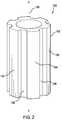
- FIG. 2is a front perspective view of another exemplary embodiment of a tubular structure for a hydraulic fracture diverter apparatus
- FIG. 3Ais a cross-sectional view of a flow of slurry approaching an exemplary embodiment of a tubular structure positioned along a pipe string;
- FIG. 3Bis a cross-sectional view of particulates within a flow of slurry beginning to collect in a vicinity of the tubular structure;
- FIG. 3Cis a cross-sectional view of the flow being diverted towards a formation of interest by a plug of solids collected about the tubular structure;
- FIG. 4is a cross-sectional view of a series of upsets for a hydraulic fracture diverter apparatus.
- FIG. 5is a cross-sectional view of a tool joint designed for use as a hydraulic fracture diverter apparatus.
- an exemplary embodiment of a hydraulic fracture diverter apparatus 10includes a substantially tubular shaped structure 12 that may be slipped onto a pipe connection or pipe joint where, or adjacent to where, fracture diversion is desired.
- the tubular structure 12may include an inner diameter 14 sized to fit onto the pipe connection, such as by having the inner diameter 14 substantially the same size or only slightly larger than an outer diameter of the pipe connection.
- the apparatus 10may include securement devices, such that the tubular structure 12 may be retained in place on the pipe connection with clamps, set screws, welds, interference or any combination of the above.
- a weld 51is illustrated in FIGS. 3A-3C .
- An outermost diameter 16 of the tubular structure 12is comparatively larger than other structure nearby on the pipe string, for disrupting a flow of slurry as it passes by the tubular structure 12 .
- the tubular structure 12includes a first end 18 and a second end 20 .
- the structure 12includes an upstream end, which is one of the first end 18 and second end 20 , and a downstream end, which is the other of the first end 18 and the second end 20 .
- the first end 18includes a first end face 22 and the second end 20 includes a second end face.
- the first end face 22includes an inner periphery 24 , such as a substantially circular shape, formed by cylindrical opening 26 and a convoluted outer periphery 28 .
- the second end facemay include a similar shape as the first end face 22 , with an inner periphery sized to accommodate the pipe string and a convoluted outer periphery.
- the tubular structure 12may be substantially symmetrically formed such that the tubular structure 12 may be reversibly oriented in either the upstream or downstream direction in use.
- the first end face 22may have a different size and/or shape than the second end face for assisting in the disruption of a flow of slurry as it passes by the tubular structure 12 .
- An outer surface 30 of the apparatus 10includes a series of longitudinally extending fins 32 that extend from the first end 18 to the second end 20 , such that portions of an outer diameter 34 of the tubular structure 12 are inwardly offset from the outermost diameter 16 of the structure 12 by a series of grooves or indentations 36 .
- the fins 32are curved such that they take on a twisted or partially spiraled arrangement.
- a hydraulic fracture diverter apparatus 100includes a tubular structure 102 with fins 104 that are straight such that they extend parallel with a longitudinal axis 106 of the tubular structure 102 .
- the tubular structure 102 shown in FIG. 2is substantially the same as the tubular structure 12 shown in FIG. 1 and therefore a detailed description of the tubular structure 102 will not be repeated.
- adjacent fins 32are separated by a groove 36 which may have a width substantially the same as or greater than the width of the fins 32 .
- the fins 32may be evenly spaced apart from each other and evenly radially distributed about the longitudinal axis 38 of the structure 12 .
- the grooves 36 that separate adjacent fins 32may also include expanded portions 40 that are larger in width than a remainder of the grooves 36 .
- the expanded portions 40take on a substantially circular shape with one arc of the circular shape formed by an indent in one fin 32 and another arc of the circular shape formed by an indent in an adjacent fin 32 .
- the enlargements 40may be provided in each groove 36 and at a same distance between the first end 18 and second end 20 , although, in alternative exemplary embodiments, the enlargements 40 may be located at varying distances from the first end 18 and second end 20 . While enlargement 40 has been shown and described with reference to circular portions of grooves 36 , other types of disruptions may be provided in either the grooves 36 or fins 32 in order to disrupt the flow of slurry passing by the tubular structure 12 .
- the tubular structure 12may have a first wall thickness measured from the inner periphery 24 of the tubular structure 12 to the outermost surface of the fin 32 , and a second wall thickness measured from the inner periphery 24 to an outer surface of the groove 36 .
- a difference between the first thickness and the second thicknessmay define a thickness of the fins 32 .
- the first and second thicknessesmay be adjusted to achieve a desired flow disruption. While curved and straight fins 32 , 104 have been respectively shown in FIGS. 1 and 2 , it should be understood that other fin structures would be within the scope of these embodiments, including, but not limited to, spiral fins, zig zag fins, circular fins, etc.
- alternate exemplary embodimentsmay include indentations that are evenly or sporadically distributed about the outer surface of a tubular structure, such that the indentations are arranged to cause particulates in slurry within the flow path to collect and remain in a vicinity of the tubular structure.
- protuberancesof varying sizes and shapes may also be distributed on the outer surface of the tubular structure to accomplish the disruption of the flow path such that particulates in slurry collect and remain in the vicinity of the tubular structure.
- a combination of indentations and protuberancesmay be employed.
- tubular structure 12has been shown and described as sized to fit over a pipe string, joint, or other connection, it should be understood that the tubular structure 12 may also be divided into two or more longitudinally split sections that can be reassembled over any portion of the pipe string and secured thereto using securement or retainment devices.
- FIGS. 3A-3Cthe hydraulic fracture diverter apparatus 10 , including the substantially tubular shaped structure 12 as described with respect to the exemplary embodiment shown in FIG. 1 , is shown employed on a pipe joint 50 of a pipe string 52 within a wellbore 54 . While not shown in FIGS. 3A-3C , it should be understood that the hydraulic fracture diverter apparatus 100 , including the substantially tubular shaped structure 102 , as well as other hydraulic fracture diverter apparatuses within the exemplary embodiments described herein, may also be employed on the pipe joint 50 .
- An annular space 56is located between the tubular structure 12 and the inner wall 58 of the wellbore 54 .
- the pipe joint 50to which the tubular structure 12 is applied, is located adjacent to a formation of interest 60 of the wellbore 54 where fracturing is desired or where fractures are to be maintained with proppant from slurry.
- the installation of the tubular structure 12 on the pipe joint 50 as describedis intended to cause bridging or plugging when a slurry 62 is flowing, as indicated by arrow 64 , in the annular space 56 of sufficient intensity.
- the flow path around the tubular structure 12 in the annular space 56 , and through the outer surface 30 of the structure 12 via the grooves and indentations 36is designed to cause particulates 68 in slurry suspension 62 to collect in the vicinity of the structure 12 , either by falling out suspension due to velocity changes or literally being centrifugally separated, as indicated by arrow 66 .
- a bridge or plug of solids 70is collected as shown in FIG. 3C .
- a method for employing the apparatus 10 in a downhole environment as described hereinis progressive fracturing, specifically the diversion of fracturing treatments into fractures via the formation of proppant/sand bridges as opposed to the more conventional hydraulic-set or swelling packers.
- the tubular structure 12 of the apparatus 10may function like a centralizer, to help centrally locate the pipe string 52 within the casing or wellbore 54 .
- the tubular structure 12is placed on a pipe connection 50 adjacent where fracture diversion is desired and the slip on structure 12 is designed to provide some benefit in terms of centralization, either by discrete fins 32 , 104 or a single spiral.
- the tubular structure 12may assist in holding the pipe string 52 off of the wall 58 while allowing flow to pass through the grooves and indentations 36 , 108 of the tubular structure 12 , 102 .
- tubular structure 12 , 102has been described with respect to FIGS. 1 and 2 , the present invention need not be limited thereto.
- a distributed series of upsets 80could be affixed to the pipe string 52 and/or pipe joint 50 to create the same effect.
- a tool joint 90could itself be designed to cause or enhance this effect rather than employing a separate tubular structure 12 on a pipe joint 50 .
- parts placed upstream of the tool or pipe joint 50could encourage bridges 70 to form at the tool or pipe joint 50 .
Landscapes
- Engineering & Computer Science (AREA)
- Life Sciences & Earth Sciences (AREA)
- Geology (AREA)
- Mining & Mineral Resources (AREA)
- Physics & Mathematics (AREA)
- Environmental & Geological Engineering (AREA)
- Fluid Mechanics (AREA)
- General Life Sciences & Earth Sciences (AREA)
- Geochemistry & Mineralogy (AREA)
- Mechanical Engineering (AREA)
- Rigid Pipes And Flexible Pipes (AREA)
- Earth Drilling (AREA)
Abstract
Description
Claims (18)
Priority Applications (3)
| Application Number | Priority Date | Filing Date | Title |
|---|---|---|---|
| US13/036,106US8662177B2 (en) | 2011-02-28 | 2011-02-28 | Hydraulic fracture diverter apparatus and method thereof |
| CA2825300ACA2825300C (en) | 2011-02-28 | 2012-01-24 | Hydraulic fracture diverter apparatus and method thereof |
| PCT/US2012/022319WO2012118571A2 (en) | 2011-02-28 | 2012-01-24 | Hydraulic fracture diverter apparatus and method thereof |
Applications Claiming Priority (1)
| Application Number | Priority Date | Filing Date | Title |
|---|---|---|---|
| US13/036,106US8662177B2 (en) | 2011-02-28 | 2011-02-28 | Hydraulic fracture diverter apparatus and method thereof |
Publications (2)
| Publication Number | Publication Date |
|---|---|
| US20120217013A1 US20120217013A1 (en) | 2012-08-30 |
| US8662177B2true US8662177B2 (en) | 2014-03-04 |
Family
ID=46718215
Family Applications (1)
| Application Number | Title | Priority Date | Filing Date |
|---|---|---|---|
| US13/036,106Active2032-03-04US8662177B2 (en) | 2011-02-28 | 2011-02-28 | Hydraulic fracture diverter apparatus and method thereof |
Country Status (3)
| Country | Link |
|---|---|
| US (1) | US8662177B2 (en) |
| CA (1) | CA2825300C (en) |
| WO (1) | WO2012118571A2 (en) |
Families Citing this family (5)
| Publication number | Priority date | Publication date | Assignee | Title |
|---|---|---|---|---|
| US8662177B2 (en)* | 2011-02-28 | 2014-03-04 | Baker Hughes Incorporated | Hydraulic fracture diverter apparatus and method thereof |
| US20140116697A1 (en)* | 2012-10-30 | 2014-05-01 | Geosierra Llc | Opening isolation for fluid injection into a formation from an expanded casing |
| US8881803B1 (en) | 2014-05-21 | 2014-11-11 | Cavin B. Frost | Desander system |
| US10119351B2 (en)* | 2015-04-16 | 2018-11-06 | Baker Hughes, A Ge Company, Llc | Perforator with a mechanical diversion tool and related methods |
| CA3014295C (en)* | 2016-02-24 | 2019-01-22 | Klx Energy Services Llc | Wellbore flow diversion tool utilizing tortuous paths in bow spring centralizer structure |
Citations (18)
| Publication number | Priority date | Publication date | Assignee | Title |
|---|---|---|---|---|
| US3351136A (en)* | 1964-09-14 | 1967-11-07 | Nelson Norman A | Casing centralizer and well bore wiper |
| US5417285A (en) | 1992-08-07 | 1995-05-23 | Baker Hughes Incorporated | Method and apparatus for sealing and transferring force in a wellbore |
| US6481494B1 (en)* | 1997-10-16 | 2002-11-19 | Halliburton Energy Services, Inc. | Method and apparatus for frac/gravel packs |
| US20030164236A1 (en) | 2000-06-30 | 2003-09-04 | Thornton John Thomas Oliver | Downhole tools |
| US6644406B1 (en)* | 2000-07-31 | 2003-11-11 | Mobil Oil Corporation | Fracturing different levels within a completion interval of a well |
| US7114562B2 (en) | 2003-11-24 | 2006-10-03 | Schlumberger Technology Corporation | Apparatus and method for acquiring information while drilling |
| US20080128131A1 (en)* | 2006-12-05 | 2008-06-05 | Halliburton Energy Services, Inc. | Methods for enhancing fracture conductivity in subterranean formations |
| US20090223667A1 (en)* | 2008-03-07 | 2009-09-10 | Halliburton Energy Services, Inc. | Sand plugs and placing sand plugs in highly deviated wells |
| US7637317B1 (en)* | 2006-10-06 | 2009-12-29 | Alfred Lara Hernandez | Frac gate and well completion methods |
| US20100084137A1 (en)* | 2008-10-02 | 2010-04-08 | Surjaatmadja Jim B | Methods and Equipment to Improve Reliability of Pinpoint Stimulation Operations |
| US7721799B2 (en) | 2006-10-06 | 2010-05-25 | Baski, Inc. | Flow control packer (FCP) and aquifer storage and recovery (ASR) system |
| US20110146994A1 (en)* | 2009-12-18 | 2011-06-23 | Petro-Hunt, Llc | Methods of Fracturing An Openhole Well Using Venturi Section |
| US20120152523A1 (en)* | 2010-09-09 | 2012-06-21 | Summit Downhole Dynamics, Ltd. | Self-Orienting Fracturing Sleeve and System |
| US20120205121A1 (en)* | 2011-02-10 | 2012-08-16 | Halliburton Energy Services, Inc. | System and method for servicing a wellbore |
| US20120217013A1 (en)* | 2011-02-28 | 2012-08-30 | Baker Hughes Incorporated | Hydraulic fracture diverter apparatus and method thereof |
| US20130032350A1 (en)* | 2011-08-05 | 2013-02-07 | Schlumberger Technology Corporation | Method Of Fracturing Multiple Zones Within A Well |
| US20130062077A1 (en)* | 2011-09-13 | 2013-03-14 | Jim Basuki Surjaatmadja | Methods and equipment to improve reliability of pinpoint stimulation operations |
| US20130081817A1 (en)* | 2011-09-29 | 2013-04-04 | Halliburton Energy Services, Inc. | Responsively Activated Wellbore Stimulation Assemblies and Methods of Using the Same |
- 2011
- 2011-02-28USUS13/036,106patent/US8662177B2/enactiveActive
- 2012
- 2012-01-24WOPCT/US2012/022319patent/WO2012118571A2/enactiveApplication Filing
- 2012-01-24CACA2825300Apatent/CA2825300C/enactiveActive
Patent Citations (26)
| Publication number | Priority date | Publication date | Assignee | Title |
|---|---|---|---|---|
| US3351136A (en)* | 1964-09-14 | 1967-11-07 | Nelson Norman A | Casing centralizer and well bore wiper |
| US5417285A (en) | 1992-08-07 | 1995-05-23 | Baker Hughes Incorporated | Method and apparatus for sealing and transferring force in a wellbore |
| US6481494B1 (en)* | 1997-10-16 | 2002-11-19 | Halliburton Energy Services, Inc. | Method and apparatus for frac/gravel packs |
| US7604059B2 (en)* | 2000-06-30 | 2009-10-20 | Brunel Oilfield Services (Uk) Limited | Downhole tools |
| US20030164236A1 (en) | 2000-06-30 | 2003-09-04 | Thornton John Thomas Oliver | Downhole tools |
| US7357178B2 (en)* | 2000-06-30 | 2008-04-15 | Brunel Oilfield Services (Uk) Limited | In and relating to downhole tools |
| US6644406B1 (en)* | 2000-07-31 | 2003-11-11 | Mobil Oil Corporation | Fracturing different levels within a completion interval of a well |
| US20040050551A1 (en)* | 2000-07-31 | 2004-03-18 | Exxonmobil Oil Corporation | Fracturing different levels within a completion interval of a well |
| US7108060B2 (en)* | 2000-07-31 | 2006-09-19 | Exxonmobil Oil Corporation | Fracturing different levels within a completion interval of a well |
| US7114562B2 (en) | 2003-11-24 | 2006-10-03 | Schlumberger Technology Corporation | Apparatus and method for acquiring information while drilling |
| US7637317B1 (en)* | 2006-10-06 | 2009-12-29 | Alfred Lara Hernandez | Frac gate and well completion methods |
| US7721799B2 (en) | 2006-10-06 | 2010-05-25 | Baski, Inc. | Flow control packer (FCP) and aquifer storage and recovery (ASR) system |
| US20080128131A1 (en)* | 2006-12-05 | 2008-06-05 | Halliburton Energy Services, Inc. | Methods for enhancing fracture conductivity in subterranean formations |
| US20090223667A1 (en)* | 2008-03-07 | 2009-09-10 | Halliburton Energy Services, Inc. | Sand plugs and placing sand plugs in highly deviated wells |
| US7690427B2 (en)* | 2008-03-07 | 2010-04-06 | Halliburton Energy Services, Inc. | Sand plugs and placing sand plugs in highly deviated wells |
| US20100084137A1 (en)* | 2008-10-02 | 2010-04-08 | Surjaatmadja Jim B | Methods and Equipment to Improve Reliability of Pinpoint Stimulation Operations |
| US20110146995A1 (en)* | 2009-12-18 | 2011-06-23 | Petro-Hunt, Llc | Methods of fracturing a well using venturi section |
| US20110146994A1 (en)* | 2009-12-18 | 2011-06-23 | Petro-Hunt, Llc | Methods of Fracturing An Openhole Well Using Venturi Section |
| US8443891B2 (en)* | 2009-12-18 | 2013-05-21 | Petro-Hunt, L.L.C. | Methods of fracturing a well using Venturi section |
| US8453743B2 (en)* | 2009-12-18 | 2013-06-04 | Petro-Hunt, L.L.C. | Methods of fracturing an openhole well using venturi section |
| US20120152523A1 (en)* | 2010-09-09 | 2012-06-21 | Summit Downhole Dynamics, Ltd. | Self-Orienting Fracturing Sleeve and System |
| US20120205121A1 (en)* | 2011-02-10 | 2012-08-16 | Halliburton Energy Services, Inc. | System and method for servicing a wellbore |
| US20120217013A1 (en)* | 2011-02-28 | 2012-08-30 | Baker Hughes Incorporated | Hydraulic fracture diverter apparatus and method thereof |
| US20130032350A1 (en)* | 2011-08-05 | 2013-02-07 | Schlumberger Technology Corporation | Method Of Fracturing Multiple Zones Within A Well |
| US20130062077A1 (en)* | 2011-09-13 | 2013-03-14 | Jim Basuki Surjaatmadja | Methods and equipment to improve reliability of pinpoint stimulation operations |
| US20130081817A1 (en)* | 2011-09-29 | 2013-04-04 | Halliburton Energy Services, Inc. | Responsively Activated Wellbore Stimulation Assemblies and Methods of Using the Same |
Non-Patent Citations (4)
| Title |
|---|
| Clem et al. "A Pragmatic Approach to Frac-Pack Tool Erosion Qualification Testing," SPE Annual Technical Conference and Exhibition, Sep. 19-22, 2010, Florence, Italy. [Abstract and Introduction Only]. |
| Clem et al. "The Science Behind Erosion Qualification Testing of Frac Pack Tools." SPE Deepwater Drilling and Completions Conference, Oct. 5-6, 2010, Galveston, Texas, USA. [Abstract and Introductioin Only]. |
| International Search Report and Written Opinion, date of mailing Sep. 12, 2012; International Application No. PCT/US2012/022319, Korean Intellectual Property Office; Written Opinion 6 pages; International Search Report 3 pages. |
| Kundert, Donald and Mike Mullen. "Proper Evaluation of Shale Gas Reservoirs Leads to a More Effective Hydraulic-Fracture Stimulation," SPE Rocky Mountain Petroleum Technology Conference, Apr. 14-16, 2009, Denver, Colorado. [Abstract and Introduction Only]. |
Also Published As
| Publication number | Publication date |
|---|---|
| WO2012118571A2 (en) | 2012-09-07 |
| CA2825300A1 (en) | 2012-09-07 |
| US20120217013A1 (en) | 2012-08-30 |
| CA2825300C (en) | 2016-05-31 |
| WO2012118571A3 (en) | 2012-11-01 |
Similar Documents
| Publication | Publication Date | Title |
|---|---|---|
| CA2825300C (en) | Hydraulic fracture diverter apparatus and method thereof | |
| US8403036B2 (en) | Single piece packer extrusion limiter ring | |
| CA2816567C (en) | Centraliser having radially extending lip for retaining collar | |
| GB2423805A (en) | Flow line for reducing axial separation of different density fluids passing through the flow line, eg tubular slug reducer | |
| US20100155064A1 (en) | Apparatus and Method for Providing an Alternate Flow Path in Isolation Devices | |
| RU2016119913A (en) | BORE LINKS CLEANING THE BAR AND THE METHOD OF THEIR APPLICATION | |
| US8881803B1 (en) | Desander system | |
| US9670742B2 (en) | Downhole stabilizer | |
| CA2892537A1 (en) | Tubular centralizer | |
| WO2012145090A2 (en) | Expandable liner hanger with helically shaped slips | |
| AU2011239247B2 (en) | A downhole centraliser | |
| RU2718897C2 (en) | Well completion system | |
| US9644478B2 (en) | Sampling assembly for a single packer | |
| US9416633B2 (en) | Screen assembly | |
| WO2020068308A1 (en) | Screen assembly and method of forming a screen assembly | |
| AU2019384090B2 (en) | Anchor and method for making | |
| US20230160285A1 (en) | Borehole tool and system | |
| US10914141B2 (en) | Screen jacket termination configuration and method | |
| AU2013273633A1 (en) | Apparatus and method for use with alternate path sand control completions | |
| AU2015250250B2 (en) | Tubular flow control apparatus and method of packing particulates using a slurry | |
| WO2020154793A1 (en) | Circumferential wear bands for oilfield tubulars |
Legal Events
| Date | Code | Title | Description |
|---|---|---|---|
| AS | Assignment | Owner name:BAKER HUGHES INCORPORATED, TEXAS Free format text:ASSIGNMENT OF ASSIGNORS INTEREST;ASSIGNOR:O'MALLEY, EDWARD J.;REEL/FRAME:026228/0936 Effective date:20110303 | |
| STCF | Information on status: patent grant | Free format text:PATENTED CASE | |
| MAFP | Maintenance fee payment | Free format text:PAYMENT OF MAINTENANCE FEE, 4TH YEAR, LARGE ENTITY (ORIGINAL EVENT CODE: M1551) Year of fee payment:4 | |
| MAFP | Maintenance fee payment | Free format text:PAYMENT OF MAINTENANCE FEE, 8TH YEAR, LARGE ENTITY (ORIGINAL EVENT CODE: M1552); ENTITY STATUS OF PATENT OWNER: LARGE ENTITY Year of fee payment:8 | |
| AS | Assignment | Owner name:BAKER HUGHES HOLDINGS LLC, TEXAS Free format text:CHANGE OF NAME;ASSIGNORS:BAKER HUGHES INCORPORATED;BAKER HUGHES, A GE COMPANY, LLC;SIGNING DATES FROM 20170703 TO 20200413;REEL/FRAME:060073/0589 | |
| MAFP | Maintenance fee payment | Free format text:PAYMENT OF MAINTENANCE FEE, 12TH YEAR, LARGE ENTITY (ORIGINAL EVENT CODE: M1553); ENTITY STATUS OF PATENT OWNER: LARGE ENTITY Year of fee payment:12 |