US8659987B2 - Adaptive modulation for fixed wireless link in cable transmission system - Google Patents
Adaptive modulation for fixed wireless link in cable transmission systemDownload PDFInfo
- Publication number
- US8659987B2 US8659987B2US13/206,183US201113206183AUS8659987B2US 8659987 B2US8659987 B2US 8659987B2US 201113206183 AUS201113206183 AUS 201113206183AUS 8659987 B2US8659987 B2US 8659987B2
- Authority
- US
- United States
- Prior art keywords
- subscriber
- traffic stream
- encoding scheme
- symbol constellation
- encoding
- Prior art date
- Legal status (The legal status is an assumption and is not a legal conclusion. Google has not performed a legal analysis and makes no representation as to the accuracy of the status listed.)
- Expired - Fee Related
Links
Images


Classifications
- H—ELECTRICITY
- H04—ELECTRIC COMMUNICATION TECHNIQUE
- H04L—TRANSMISSION OF DIGITAL INFORMATION, e.g. TELEGRAPHIC COMMUNICATION
- H04L5/00—Arrangements affording multiple use of the transmission path
- H04L5/003—Arrangements for allocating sub-channels of the transmission path
- H04L5/0037—Inter-user or inter-terminal allocation
- H—ELECTRICITY
- H04—ELECTRIC COMMUNICATION TECHNIQUE
- H04L—TRANSMISSION OF DIGITAL INFORMATION, e.g. TELEGRAPHIC COMMUNICATION
- H04L1/00—Arrangements for detecting or preventing errors in the information received
- H04L1/0001—Systems modifying transmission characteristics according to link quality, e.g. power backoff
- H04L1/0002—Systems modifying transmission characteristics according to link quality, e.g. power backoff by adapting the transmission rate
- H04L1/0003—Systems modifying transmission characteristics according to link quality, e.g. power backoff by adapting the transmission rate by switching between different modulation schemes
- H—ELECTRICITY
- H04—ELECTRIC COMMUNICATION TECHNIQUE
- H04L—TRANSMISSION OF DIGITAL INFORMATION, e.g. TELEGRAPHIC COMMUNICATION
- H04L1/00—Arrangements for detecting or preventing errors in the information received
- H04L1/0001—Systems modifying transmission characteristics according to link quality, e.g. power backoff
- H04L1/0009—Systems modifying transmission characteristics according to link quality, e.g. power backoff by adapting the channel coding
- H—ELECTRICITY
- H04—ELECTRIC COMMUNICATION TECHNIQUE
- H04L—TRANSMISSION OF DIGITAL INFORMATION, e.g. TELEGRAPHIC COMMUNICATION
- H04L1/00—Arrangements for detecting or preventing errors in the information received
- H04L1/0001—Systems modifying transmission characteristics according to link quality, e.g. power backoff
- H04L1/0023—Systems modifying transmission characteristics according to link quality, e.g. power backoff characterised by the signalling
- H04L1/0025—Transmission of mode-switching indication
- H—ELECTRICITY
- H04—ELECTRIC COMMUNICATION TECHNIQUE
- H04L—TRANSMISSION OF DIGITAL INFORMATION, e.g. TELEGRAPHIC COMMUNICATION
- H04L5/00—Arrangements affording multiple use of the transmission path
- H04L5/0001—Arrangements for dividing the transmission path
- H04L5/0003—Two-dimensional division
- H04L5/0005—Time-frequency
- H04L5/0007—Time-frequency the frequencies being orthogonal, e.g. OFDM(A) or DMT
Definitions
- This inventionrelates generally to communication systems and more specifically to adaptive modulation in a fixed wireless communication system.
- a significant component of the cost of creating this infrastructureis the cost of providing fixed cabling in the Customer Access Network (“CAN”).
- CANCustomer Access Network
- a method of reducing the cost of a broadband CANis to use fixed broadband wireless to provide communication links between subscribers and a fixed backbone network.
- the Broadband Wireless Internet Forum (“BWIF”)has created a standard for the provision of fixed broadband wireless.
- the standardinvolves the use of a Wireless Access Termination System (“WATS”) to broadcast information to a group of subscribers on a downstream channel.
- WATSWireless Access Termination System
- the subscriberssend information to the WATS using a shared upstream channel.
- Each subscriberis allocated access to a channel in accordance with a Medium Access Protocol (“MAC”).
- MACMedium Access Protocol
- a limitation of the BWIF specificationis that the subscribers communicate on the upstream channel using the same modulation and encoding schemes.
- the characteristics of the upstream channelcan vary depending on the location of an individual subscriber. Therefore, use of a modulation and encoding scheme that is appropriate for certain channel conditions can unnecessarily impact on the Quality of Service (“QoS”) experienced by individual subscribers.
- QoSQuality of Service
- a modulation schemeis chosen to provide high throughput in a channel with high Signal to Interference plus Noise Ratio (“SINR”), then subscribers in locations where the upstream channel has a low SINR will experience very high Bit Error Rates (“BER”).
- SINRSignal to Interference plus Noise Ratio
- FIG. 1is a semi-schematic view illustrating a wireless communications network
- FIG. 2is a semi-schematic view illustrating a wireless access termination system connected to a backbone network and a wireless modem connected to customer premise equipment at a subscriber location;
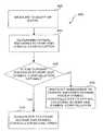
- FIG. 3is a flow diagram illustrating steps performed by a wireless modem to transmit data on an upstream channel
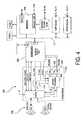
- FIG. 4is a semi-schematic circuit diagram of a wireless modem
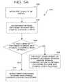
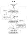
- FIGS. 5A and 5Bare flow diagrams illustrating steps performed by a wireless access termination system to decide which encoding scheme and symbol constellation a subscriber should use to transmit on an upstream channel;
- FIG. 6is a graph that generally illustrates different characteristics of an additive white Gaussian noise channel, a Ricean channel and a Reyleigh fading channel;
- FIG. 7is a semi-schematic block diagram illustrating components of a wireless access termination system used to determine which encoding scheme and symbol constellation a subscriber should use to transmit on an upstream channel;
- FIG. 8is a flow diagram illustrating steps used by a wireless access termination system to allocate an encoding scheme and symbol constellation to a subscriber registering with the wireless access termination system;
- FIG. 9is a flow diagram illustrating communications between a wireless modem and a wireless access termination system that cause the wireless modem to adopt a new encoding scheme and/or symbol constellation;
- FIG. 10is a timing diagram illustrating a delay between a decision by a wireless access termination system that a wireless modem should change encoding scheme and/or symbol constellation and the wireless modem changing encoding scheme and/or symbol constellation;
- FIG. 11is a flow diagram illustrating steps performed by a wireless access termination system to allocate transmission timeslots on an upstream channel to subscribers;
- FIG. 12is a semi-schematic block diagram illustrating components of a wireless access termination system used to determine which encoding scheme and symbol constellation a subscriber should use to transmit on an upstream channel and to allocate timeslots on the upstream channel to subscribers;
- FIG. 13is a flow diagram illustrating the steps performed by a wireless access termination system to allocate timeslots to subscribers, when a subscriber changes encoding scheme and/or symbol constellation.
- the network 100includes a backbone network 102 that is terminated by a Wireless Access Termination System (“WATS”) 104 .
- the WATS 104includes an indoor unit (“WATS-IDU”) 106 that is connected to an outdoor unit and antenna (“WATS-ODU”) 108 .
- the WATSbroadcasts data to subscribers 110 on a downstream channel and the subscribers send information to the WATS using a shared upstream channel.
- the upstream channelhas a spectral bandwidth of between 6 MHz and 15 MHz.
- the subscribers 110compete for access to the upstream channel. Therefore, the upstream channel is divided into time slots referred to as minislots. Each minislot is allocated to a subscriber 110 , which can transmit information on the upstream channel for the duration of that minislot.
- Minislotsare allocated to subscribers 110 by the WATS 104 . Subscribers 110 communicate their bandwidth requirements to the WATS 104 and the WATS assigns minislots to the subscribers based on their bandwidth requirements.
- the minislot assignmentsare communicated to the subscribers 110 via broadcast on the downstream channel.
- the upstream channelcan be further divided into subchannels and each subchannel can have different length minislots. Preferably, the channel is divided into subchannels of one half or one fourth the total channel bandwidth.
- the upstream channelis non-line of sight. Therefore, in one preferred embodiment of the network 100 , signals on the upstream channel are transmitted using Vector Orthogonal Frequency Division Multiplexing (“VOFDM”).
- VOFDMcan be used because it is robust in the presence of the severe multipath distortion generally present in high capacity, non-line of sight wireless channels. Instead of sending all of the data on a single very high speed channel that occupies the entire channel bandwidth, VOFDM involves separating the data into a number of separate streams and then transmitting each stream on a separate carrier at a much lower rate. Spectral efficiency is maximized by ensuring that the carriers are spaced so that the signals transmitted on the carriers are orthogonal. The signals transmitted on the carriers are orthogonal when the amplitude of all of the signals at a particular frequency are zero except for the signal being transmitted on that carrier frequency.
- Estimation of the upstream channelis achieved by dividing the channel into a total of N carriers or tones, including N data data tones, v training tones and N zero zero tones.
- the training tonesenable the WATS 104 to estimate the characteristics of the upstream channel.
- the training tonesare spaced at intervals of N/v, with the first training tone placed at the lower frequency band edge.
- the zero tonesare used to prevent the VOFDM signal interfering with adjacent channels.
- the zero tonesare placed in the N zero /2 left most and N zero /2 right most tones that are not already designated as training tones.
- the remaining tonesare dedicated to the transmission of data.
- Nis 512
- N datais 396
- v64
- N zero52. In other embodiments more or less training and zero tones can be used.
- the subscriber equipmentis illustrated in greater detail in FIG. 2 .
- the subscriber equipmentincludes a Wireless Modem (“WM”) 200 connected to customer premise equipment 202 .
- the WMincludes an indoor unit (“WM-IDU”) 204 that is connected to an outdoor unit and antenna (“WM-ODU”) 206 .
- the WM-IDUcomprises a controller 208 and memory 210 , which are connected to a VOFDM transmitter 212 and a receiver 214 . Both the transmitter 212 and the receiver 214 have digital output and are connected to an analog module 216 , which converts the digital output to an analog radio frequency signal for transmission.
- the controller 208 and memory 210are connected to the customer premise equipment 202 and the analog module 216 is connected to the WM-ODU 206 .
- the WM-ODU 206comprises an antenna for transmitting and receiving radio frequency signals. More preferably, the WM-ODU 206 comprises multiple antennas for improved reception of the VOFDM signal.
- the WM 200demodulates and decodes data broadcast by the WATS 104 on the downstream channel. It also codes, modulates and transmits data from the subscriber to the WATS 104 on the upstream channel.
- the functions performed by the WM 200 in encoding and modulating data for transmissionare illustrated by the flow chart shown as FIG. 3 .
- the encoding and modulation processbegins when the subscriber equipment 202 generates a burst of data for transmission to the WATS 104 .
- the controller 208then performs the step 302 of dividing the data into blocks, where each block represents the amount of data to be transmitted in a single VOFDM burst.
- the data blocksare encoded using an error correcting encoding on the transmitter 212 in the step 304 .
- the error correcting encodingenables the WATS 104 to correct some of the errors that can result during transmission.
- Reed-Solomon encodingis used.
- Reed-Solomon encodingis a linear block Forward Error Correction (“FEC”) technique which increases the block size by R bytes.
- FEClinear block Forward Error Correction
- the Reed-Solomon encodingenables the WATS to correct up to R/2 byte errors in each encoded data block.
- FEClinear block Forward Error Correction
- the encoded datais then scrambled by the transmitter 212 in the step 306 , which reduces the probability of long sequences of ones or zeros being generated. Long sequences of ones or zeros can result in the peak-to-mean power ratio of the transmitted signal being undesirably high.
- the convolutional encoderis composed of two components. The first is a standard length—7, rate—1 ⁇ 2 convolutional encoder, utilizing a standard pair of generator polynomials ( 171 , 133 ). The second is a standard puncturing module with patterns for producing coding rates of 2 ⁇ 3 and by deleting bits from the output of the rate 1 ⁇ 2 encoder. Each block is encoded independently, therefore, the data is fully flushed from the encoder between bursts. This is done by feeding six 0 bits into the encoder.
- the transmitter 212performs the bit interleaving step 310 .
- the bit interleavingensures that narrowband interference which can corrupt several adjacent data tones does not degrade the performance of communications on the upstream channel.
- the errorsare spread throughout the data stream. Spreading the errors increases the likelihood that FEC encoding can be used to correct the errors. A large number of errors in a small number of data blocks can result in those data blocks being lost despite the FEC encoding. However, if the same number of errors are spread over a larger number of data blocks, then there is a greater likelihood that the FEC encoding can be used to correct the errors so that none of the data blocks will be lost.
- the interleaved bitsare mapped to symbols in the step 312 by the transmitter 212 .
- the symbols chosendepend on the modulation scheme being used by the WM 200 .
- the WM 200is capable of transmitting using Quadrature Phase Shift Keying (“QPSK”), 16 Quadrature Amplitude Modulation (“16-QAM”) or 64-QAM.
- QPSKQuadrature Phase Shift Keying
- 16-QAM16 Quadrature Amplitude Modulation
- 64-QAM64-QAM.
- the WMcan be configured to provide a greater variety of modulation techniques.
- the transmitter 212inserts training and zero tones and then performs an Inverse Fast Fourier Transform (“IFFT”) 314 .
- IFFTInverse Fast Fourier Transform
- the IFFTensures that the transmitted signals are orthogonal.
- the complex baseband OFDM signalis the inverse Fourier transform of the N QAM input symbols.
- An IFFTis used to reduce the number of calculations required to generate the baseband VOFDM signal.
- the transmitter 22performs the step 316 of adding a cyclic prefix to the IFFT output to ensure orthogonality of the transmitted signals in the presence of a timing offset.
- the FIR filteringfilters out reflections and provides spectral shaping to increase spectral efficiency.
- the transmitter 212uses a frequency controlled oscillator to shift the complex filtered output to a desired Intermediate Frequency (“IF”) and discards the imaginary portion of the signal to provide a real, two-sided signal capable of being applied to a digital to analog converter in the analog module 216 .
- IFIntermediate Frequency
- the transmitter and receiverare implemented using a BCM2200 integrated circuit 400 manufactured by Broadcom Corporation of Irvine, Calif.
- the BCM2200is connected to the memory and controller by a bus 402 .
- the controlleris implemented using a BCM3310 communications processor 404 manufactured by Broadcom Corporation.
- the BCM2200is also connected to the analog module 216 .
- the analog module 216is implemented using discrete components in a manner well known in the art and comprises a digital to analog converter 406 for the upstream channel, an analog-to-digital converter 408 for the downstream channel, a local voltage controlled oscillator 410 for shifting between the IF and the transmission frequency and filters 412 for selecting the upstream or downstream channel signal and for removing reflections and distortions.
- the upstream and downstream channel frequenciesare located within the U.S. MMDS Band (2.500-2.686 GHz) of the RF spectrum.
- the upstream and downstream channel frequenciesare located with the U.S. MDS Band (2.150-2.162 GHz), the unlicensed UNII Band or the European Fixed Wireless Band.
- the WATS-IDU 106comprises a controller 250 and memory 252 connected to a transmitter 254 and a VOFDM receiver 256 .
- both the transmitter 254 and receiver 256are connected to an analog module 258 .
- the controlleris connected to the backbone network 102 and the analog module is connected to the WATS-ODU 108 .
- the WATS 104demodulates and decodes data broadcast by the WM 200 on the upstream channel. It also codes, modulates and transmits data from the backbone network 102 to the subscriber 110 on the downstream channel.
- the performance of communications on a channelcan be quantified using certain metrics such as Signal to Interference plus Noise Ratio (“SINR”), Bit Error Rate (“BER”), Codeword Error Rate (“CER”), Symbol Error Rate (“SER”), number of corrected bit errors, number of corrected codeword errors, the metrics within a Viterbi decoder, the Ricean K factor or other similar measurements.
- SINRSignal to Interference plus Noise Ratio
- BERBit Error Rate
- CERCodeword Error Rate
- SERSymbol Error Rate
- the encoding and modulation scheme required to satisfy the above minimum requirementvaries depending on the quality of the channel where a particular subscriber 110 is located.
- the symbol rateis fixed for each channel.
- individual subscribers 110are able to transmit using different encoding schemes and symbol constellations.
- the encoding scheme and symbol constellation used by a subscriberis controlled by the WATS 104 .
- the WATS 104receives a signal from a subscriber 110 , the WATS measures the quality of the signal and directs the subscriber to adopt a new encoding scheme and/or symbol constellation if the subscriber is not optimally utilizing the channel.
- subscribers 110 that experience a high quality upstream channelare able to achieve higher throughputs than subscribers 110 that experience a low quality upstream channel and all subscribers 110 are able to satisfy the minimum requirements for transmission on the upstream channel.
- FIG. 5Aillustrates a process used by a WATS 104 to allocate an encoding scheme and symbol constellation to a subscriber 110 .
- the WATS 104measures the quality of the received signal transmitted by the subscriber 110 on the upstream channel in the step 502 .
- the WATS 104then performs the step 504 of determining the optimal encoding scheme and symbol constellation for the transmission of signals on a channel with the quality of the measured quality of the upstream channel. If the optimal encoding scheme and symbol constellation is determined to be different to the encoding scheme and symbol constellation being used by the subscriber 110 in the step 506 , then the WATS 104 instructs the subscriber to change encoding scheme and/or symbol constellation to the optimal encoding scheme and symbol constellation in the step 508 . If the encoding scheme and symbol constellation being used by the subscriber 110 is the same as the optimal encoding scheme and symbol constellation, then the WATS 104 allows the subscriber to continue to transmit using that encoding scheme and symbol constellation 510 .
- FIG. 5Bshows a process that can be used to determine the optimal encoding scheme and symbol constellation for transmission of signals on a channel with the quality of the measured quality of the upstream channel.
- the WATSperforms the step 502 of measuring the quality of the received signal from the subscriber 110 , then the WATS compares the measured quality of the channel to a set of lower thresholds for the use of the encoding scheme and symbol constellation being utilized by the subscriber in the step 550 . If the thresholds are not satisfied then the WATS 104 performs the step 552 of selecting a more robust encoding scheme and/or a smaller symbol constellation and then repeating the step 550 .
- the WATS 104compares the measured quality of the channel to a set of upper thresholds for use of that encoding scheme and symbol constellation in the step 554 . If the thresholds are not satisfied, then the WATS selects a less robust encoding scheme and/or a larger symbol constellation in the step 556 and then repeats the step 554 comparing the measured signal quality to the upper threshold for use of the selected encoding scheme and symbol constellation.
- the WATS 104When an encoding scheme and symbol constellation is found for which the measured quality of the channel satisfies the upper thresholds for that encoding scheme, then the WATS 104 performs the step 558 of selecting that encoding scheme and symbol constellation as the optimal encoding scheme and symbol constellation.
- the communications network 100 of the present inventionis able to predict degradation of the upstream channel and cause subscribers 110 to change encoding schemes and/or symbol constellations prior to the degradation occurring. Predicting degradation enables the communications network 100 to respond before it fails to satisfy the minimum transmission requirements. Any of the metrics mentioned above can be used to measure channel quality, however, there are limitations in their ability to predict channel degradation.
- FIG. 6illustrates the relationship between SINR and the codeword error probability for an Additive White Gaussian Noise (“AWGN”) channel, a Ricean channel and a Rayleigh channel.
- the curve 600illustrates the relationship between SINR and the codeword error probability for an AWGN channel.
- the curve 602illustrates the relationship between codeword error probability for a Ricean channel and the curve 604 illustrates the relationship between codeword error probability for a Rayleigh channel.
- the line 606indicates a codeword error probability of 10 ⁇ 7 .
- a codeword error probability that is less than 10 ⁇ 7satisfies the minimum operating requirement for one embodiment of the wireless communications system 100 .
- the codeword error probability experienced at the SINR indicated by the line 608satisfies the minimum transmission requirement.
- a small decrease in SINRresults in the probability exceeding the minimum transmission requirement.
- the absence of a gradual increase in CERrenders it difficult for the WATS to predict that the channel is degrading using this metric alone.
- FIG. 6also illustrates that measurement of SINR alone is unlikely to accurately predict channel degradation because the threshold at which the channel degrades is dependent on the type of the upstream channel.
- the SINR received at the WATS 104is as indicated by the line 608 .
- the minimum transmission requirementis met if the channel is an AWGN channel.
- the channelis either a Ricean channel or a Rayleigh channel, then the minimum transmission requirement is not met.
- the average channel SINRis unlikely to predict a decrease in performance arising from strong narrowband interference.
- the variance in the SINR or the SERare more useful for detecting narrowband interference.
- Other metricscan be used for predicting decreases in performance irrespective of the channel type including corrected bit errors, corrected codeword errors, Ricean K-factor and the Viterbi path metrics.
- the WATS 104compares the SINR or SER to threshold values in the decision steps 550 and 554 of FIG. 5B . More preferably, the WATS 14 compares the result of the following function to the threshold values.
- the WATS 104compares a number of the above metrics to a set of predetermined thresholds and the WATS 104 requires a change in encoding scheme and/or symbol constellation if any of the thresholds are not satisfied.
- the Elements of a controller 250 and receiver 256 used by a WATS 104 to measure channel quality and determine the encoding scheme that a subscriber 110 can use to make optimal use of its allocated transmission timeis illustrated in FIG. 7 .
- the receiver 256comprises an upstream burst receiver 702 connected to a decoding block 704 and an encoding scheme and symbol constellation assignment block 706 .
- the decoding block 704is also connected to the encoding scheme and symbol constellation assignment block 706 and a MAC layer block 708 .
- a VOFDM burst signalis received at the WATS-ODU 108 and is input to the upstream burst receiver 702 .
- the upstream burst receiver 702demodulates the VOFDM burst signal and at the same time, measures the SINR for each tone in the signal.
- the upstream burst receiver 702outputs the demodulated data to the decoder block 704 .
- the decoder blockconverts the symbols to bit representations, then de-interleaves the received bits and performs convolutional decoding.
- the convolutional decodingis performed using a digital Viterbi decoder.
- sequential decoders, analog Viterbi decoders or other decodersmay be used.
- the bitsare de-scrambled and then the FEC encoding is used to perform forward error correction.
- the decoder block 704obtains statistics associated with the FEC such as the BER, CER, corrected bit errors and corrected codewords.
- the decoded datathen passes to the MAC layer block 708 , which reconstructs the packets and places the received data in memory.
- the measurements of SINR, BER and CERprovide inputs to the encoding scheme and symbol constellation assignment block 706 , which uses these statistics to decide whether the subscriber 110 should change to a more or less robust encoding scheme and/or a smaller or larger signal constellation in accordance with the procedure outlined above.
- the encoding scheme and symbol constellation assignment block 706determines that the subscriber 110 can use a more efficient encoding scheme, then the encoding scheme and symbol constellation assignment block 706 generates a message to be sent to the subscriber 110 instructing it to change encoding schemes. This message is then transmitted by the WATS 104 on the downstream channel.
- the efficiency of the process illustrated in FIG. 5is increased by establishing a set of predetermined encoding scheme and symbol constellation configurations.
- Each of the predetermined encoding scheme and symbol constellation configurationsis designed to satisfy the minimum requirements and provide high throughput for a given range of channel qualities.
- the WATS 104can then direct the subscriber 110 to adopt the predetermined encoding scheme and symbol constellation configuration most appropriate for use at the measured channel quality.
- the predetermined encoding scheme and symbol constellation configurations used in one preferred embodiment of the communications network 100are shown in TABLE 2.
- ID NN zero N data
- Sym. Const. RConv. I 128 16 22 90 64-QAM 14 0.833 II 128 16 22 90 64-QAM 14 0.667 III 128 16 22 90 64-QAM 10 0.5 IV 128 16 22 90 16-QAM 10 0.5 V 128 16 22 90 QPSK 10 0.667
- IDis the encoding scheme and symbol constellation identifier
- Nis the number of VOFDM tones
- vis the number of training tones
- N zerois the number of zero tones
- N datais the number of data tones
- Symb. Constis the symbol constellation being used
- Ris the number bytes added by the Reed-Solomon encoding
- Conv.is the rate of the convolutional encoder.
- the thresholds at which these different encoding scheme and symbol constellation configurations are usedare determined automatically by the WATS 104 using known test transmissions from the subscriber 110 .
- a set of thresholdsare defined for the minimum SINR required for the encoding scheme and signal constellation configuration to be used. These thresholds are shown in TABLE 3.
- ID SINR threshold I>21 dB II >16 dB III >12 dB IV >9 dB V >4 dB
- thresholdsare defined for a number of performance metrics in combination or separately.
- the transmitter 254 and receiver 256are implemented using a BCM92210 linecard manufactured by Broadcom Corporation and the controller 250 is implemented using a Pentium microprocessor manufactured by Intel Corporation of Santa Clara, Calif. In other embodiments other transmitters, VOFDM receivers and controllers or microprocessors can be used.
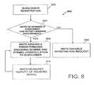
- FIG. 8a process 800 for allocating an encoding scheme and symbol constellation to a new subscriber 110 is illustrated.
- the subscriber 110attempts to establish communications or register with the WATS 104 by sending a registration request on the upstream channel.
- the subscriber 110attempts to register with the WATS 104 using the most robust of the predetermined encoding scheme and symbol constellation configurations.
- the WATS 104receives the registration request transmission and then performs the step 804 of determining if the subscriber can support the minimum requirements for transmission.
- the WATS 104completes this step by measuring the characteristics of the received transmission and determining whether they satisfy the minimum requirements. If the minimum requirements are not met, the WATS 104 refuses the registration request 806 .
- a refusalmust be made because the subscriber WM 200 cannot transmit using a more robust encoding scheme. Therefore, the subscriber 110 cannot alter the encoding or modulation of the transmission in any way that will cause the minimum requirements to be met.
- the WATS 104performs the step 808 of assigning a predetermined encoding scheme and symbol constellation configurations to the subscriber 110 . Once this predetermined encoding scheme and symbol constellation configuration assignment has been completed, future transmissions by the subscriber 110 must use this encoding scheme unless the WATS 104 directs otherwise.
- the WATS 104continually monitors the quality of subscriber transmissions 810 and instructs the subscribers 110 to change encoding schemes and/or symbol constellations as required.
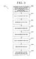
- a process 900 used in one embodiment of the communications network 100 to change the encoding scheme and symbol constellation sizes being used by a WM 200is illustrated in FIG. 9 .
- the encoding scheme and symbol constellation assignment block 706determines that a change of encoding scheme and/or symbol constellation is required.
- the WATS 104then performs the step 904 of transmitting an Encoding and Symbol constellation Change Request (“ESC-Req”) to the WM 200 .
- ESC-ReqEncoding and Symbol constellation Change Request
- the WM 200receives the ESC-Req. Once the ESC-Req is received, the WM 200 then performs the step 908 of transmitting an Encoding and Symbol constellation Change Response (“ESC-Rsp”).
- ESC-RspEncoding and Symbol constellation Change Response
- the WATS 104receives the ESC-Rsp in step 910 and transmits a Encoding and Symbol constellation Change Acknowledgment (“ESC-Ack”) in step 912 .
- ESC-AckEncoding and Symbol constellation Change Acknowledgment
- the delay between the decision by the WATS 104 that a subscriber 110 must adopt a new encoding scheme and symbol constellation and the adoption by the subscriber of the new encoding scheme and symbol constellationis illustrated in FIG. 10 .
- the delayis equal to the sum of the ESC-Req transmission time 1000 , the WM processing time 1002 , the ESC-Rsp transmission time 1004 , the WATS processing time 1006 and the ESC-Ack transmission time 1008 .
- the subscriber 110is unable to transmit data during the period from when the ESC-Req is received by the WM 200 until when the ESC-Ack is received by the WM. Therefore, frequent changes of encoding scheme and/or symbol constellation can reduce WM 200 throughput.
- the predetermined encoding scheme and symbol constellation configurationsare chosen so that the range in channel qualities that the encoding scheme and symbol constellation configurations are designed to be utilized within overlap with each other. This overlapping provides hysteresis, which reduces the frequency with which a subscriber 110 must alter encoding scheme and symbol constellations. Reducing the frequency of changing encoding scheme and/or symbol constellation eliminates the communication overhead associated with these changes and increases throughput by enabling the subscriber 110 to spend more time transmitting data.
- SINR ranges for use of encoding scheme and constellation size configurationsComb. ID Min. SINR Max. SINR I 21 dB N/A II 16 dB 22 dB III 12 dB 17 dB IV 9 dB 13 dB V 4 dB 10 dB
- the communications network 100 of the present inventiontransmits different types of traffic, such as voice, data or video traffic. These different types of traffic generally have different Quality of Service (“QoS”) requirements.
- QoSQuality of Service
- the QoS required by a type of trafficis often determined by the nature of the traffic. Voice traffic has low communication bandwidth requirements but is intolerant to delays or information arriving out of order. The same is also true of video traffic, but video traffic also requires much higher bandwidths.
- Data transferhas different characteristics. Data transfer usually occurs in bursts involving periods where little bandwidth is required. Delay and order are largely irrelevant in data transfers, the primary requirement is often speed.
- the customer premise equipment 202generates traffic streams and specifies the QoS required for transmission of each traffic stream. Consequently, the network 100 is configured such that the traffic stream is transmitted on the upstream channel if there are sufficient minislots available to guarantee that the QoS requirements will be met.
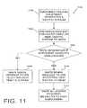
- a process 1100 used by communications network 100 to determine if the upstream channel can meet the QoS requirements of a new traffic streamis illustrated in FIG. 11 .
- the customer premise equipmentgenerates a traffic stream in the step 1102 .
- the WM 200Prior to commencing transmission of the traffic stream, the WM 200 performs the step 1104 of sending a message to the WATS 104 requesting that the WM 200 be allowed to transmit a new traffic stream on the upstream channel.
- the messagealso contains information concerning the QoS required by the new traffic stream.
- the WATS 104then is faced with the decision 1106 of determining if it can allocate sufficient minislots to the WM 200 to satisfy the requested QoS requirements.
- the WATS 104If the WATS 104 is unable to allocate enough minislots, then it performs the step 1108 of sending a message to the WM 200 .
- the messagecommunicates the WATS refusal to accept transmission of the new traffic stream on the upstream channel. If sufficient minislots are available to satisfy the requested QoS requirements, then the WATS 104 completes steps 1110 and 1112 by sending a message to the WM 200 accepting the new traffic stream and then allocating the required minislots to the WM 200 .
- the communications network 100 of the present inventionsupports adaptive encoding and modulation on the upstream channel. Changes in the encoding scheme and/or symbol constellation used by a WM 200 can effect the QoS experienced by the traffic streams that the WM is transmitting. If the WM 200 changes to a more robust encoding scheme and/or a smaller symbol constellation, then its effective data rate on the upstream channel is reduced. Conversely, if the WM 200 changes to a less robust encoding scheme and/or a larger symbol constellation then, the effective data rate of the WM 200 on the upstream channel increases. These changes in effective data rate can effect the QoS experienced by the traffic streams being transmitted by the WM 200 .
- Traffic streams that demand a constant data rateare particularly affected by changes which reduce the effective data rate of the WM 200 .
- the WATS 104can allocate additional minislots to the WM to ensure the QoS requirements of its traffic streams are met.
- the WATS 104can reallocate some of the minislots allocated to that WM 104 , when its effective data rate is increased. The minislots can only be reallocated if doing so does not jeopardize the QoS of the WM 200 traffic streams.
- each traffic streamis assigned a priority. Therefore, if there are insufficient unallocated minislots to guarantee the QoS of all traffic streams, then the WATS 104 can reallocate minislots from traffic streams with low priorities to traffic streams with higher priorities.
- FIG. 12An embodiment of a controller 250 ′ and receiver 256 ′ in accordance with practice of the present invention are illustrated in FIG. 12 .
- the receiver 256 ′is similar to the receiver 256 of FIG. 7 and the controller 250 ′ is similar to the controller 250 of FIG. 7 , with the addition of a minislot scheduler 1200 that is connected to the encoding scheme and symbol constellation assignment block 706 .
- the minislot scheduler 1200maintains a schedule of the minislots assigned to different subscriber traffic streams and the priorities of those streams.
- the minislot scheduler 1200also allocates minislots to the WMs 200 and reallocates scheduled minislots, when the upstream channel is congested.
- a process 1300 used by the controller 250 ′ for allocating minislots in response to changes in the encoding scheme and/or symbol constellation used by a WM 200is illustrated in FIG. 13 .
- the encoding scheme and symbol constellation assignment block 706determines that a change in encoding scheme is required 1302 , it communicates its decision to the WM 200 and the minislot scheduler 1200 in the step 1304 .
- the minislot scheduler 1200then performs the step 1306 of determining whether the WM 200 has been allocated sufficient minislots to meet the QoS requirements of the traffic streams the WM is transmitting at that time.
- the minislot scheduler 1200must make a decision 1308 . This decision requires the minislot scheduler 1200 to determine if the current minislot allocation of the WM 200 is in excess of the number of minislots required to meet the QoS requirements of the traffic streams being transmitted by the WM 200 . If the current minislot allocation is not in excess of the number of minislots required to meet the QoS requirements of the traffic streams being transmitted by the WM 200 , then the minislot scheduler 1200 does nothing 1310 .
- the minislot scheduler 1200causes a message to be sent to the WM informing it that the excess minislots are no longer assigned to it.
- the minislot scheduler 1200is then free to allocate these minislots to other traffic streams as required.
- the minislot schedulermakes the decision 1314 whether there are enough unallocated minislots to meet the requirements of the WM following the change in encoding scheme. If there are sufficient unallocated minislots, then the minislot scheduler 1200 allocates the minislots to the WM 200 and causes a message to be sent to the WM informing it of the new minislot allocation.
- the minislot allocation systemdetermines in the step 1318 if the minislot requirements of the WM can be met by the reallocation of previously allocated minislots. For the minislot requirements of the WM 200 to be met in this way, the traffic streams being transmitted by the WM must have higher priority than other traffic streams on the upstream channel. If this is the case, then the required minislots are assigned to the WM 200 in the step 1320 by reallocating minislots assigned to lower priority traffic streams.
- the minislot schedulercauses a message to be sent to the WM informing it that there are insufficient minislots available.
- the WM 200must then perform the step 1322 of negotiating new QoS requirements for its traffic streams with the customer premise equipment 202 .
Landscapes
- Engineering & Computer Science (AREA)
- Signal Processing (AREA)
- Computer Networks & Wireless Communication (AREA)
- Quality & Reliability (AREA)
- Digital Transmission Methods That Use Modulated Carrier Waves (AREA)
- Error Detection And Correction (AREA)
- Detection And Prevention Of Errors In Transmission (AREA)
- Mobile Radio Communication Systems (AREA)
Abstract
Description
| TABLE 2 |
| Encoding scheme and symbol constellation configurations |
| Comb. ID | N | ν | Nzero | Ndata | Sym. Const. | R | Conv. |
| I | 128 | 16 | 22 | 90 | 64-QAM | 14 | 0.833 |
| II | 128 | 16 | 22 | 90 | 64-QAM | 14 | 0.667 |
| III | 128 | 16 | 22 | 90 | 64- | 10 | 0.5 |
| IV | 128 | 16 | 22 | 90 | 16- | 10 | 0.5 |
| V | 128 | 16 | 22 | 90 | QPSK | 10 | 0.667 |
Where Comb. ID is the encoding scheme and symbol constellation identifier; N is the number of VOFDM tones; v is the number of training tones; Nzerois the number of zero tones; Ndatais the number of data tones; Symb. Const, is the symbol constellation being used; R is the number bytes added by the Reed-Solomon encoding; and Conv. is the rate of the convolutional encoder.
| TABLE 3 |
| Minimum SINR thresholds |
| Comb. ID | SINR threshold | ||
| I | >21 dB | ||
| II | >16 dB | ||
| III | >12 dB | ||
| IV | >9 dB | ||
| V | >4 dB | ||
| TABLE 4 |
| SINR ranges for use of encoding scheme |
| and constellation size configurations |
| Comb. ID | Min. SINR | Max. SINR |
| I | 21 dB | N/A |
| II | 16 dB | 22 dB |
| III | 12 dB | 17 dB |
| IV | 9 dB | 13 dB |
| V | 4 | 10 dB |
Claims (14)
Priority Applications (1)
| Application Number | Priority Date | Filing Date | Title |
|---|---|---|---|
| US13/206,183US8659987B2 (en) | 2000-10-16 | 2011-08-09 | Adaptive modulation for fixed wireless link in cable transmission system |
Applications Claiming Priority (5)
| Application Number | Priority Date | Filing Date | Title |
|---|---|---|---|
| US24104600P | 2000-10-16 | 2000-10-16 | |
| US09/858,926US7016296B2 (en) | 2000-10-16 | 2001-05-15 | Adaptive modulation for fixed wireless link in cable transmission system |
| US11/261,234US7706246B2 (en) | 2000-10-16 | 2005-10-27 | Adaptive modulation for fixed wireless link in cable transmission system |
| US12/654,816US8023396B2 (en) | 2000-10-16 | 2010-01-05 | Adaptive modulation for fixed wireless link in cable transmission system |
| US13/206,183US8659987B2 (en) | 2000-10-16 | 2011-08-09 | Adaptive modulation for fixed wireless link in cable transmission system |
Related Parent Applications (1)
| Application Number | Title | Priority Date | Filing Date |
|---|---|---|---|
| US12/654,816ContinuationUS8023396B2 (en) | 2000-10-16 | 2010-01-05 | Adaptive modulation for fixed wireless link in cable transmission system |
Publications (2)
| Publication Number | Publication Date |
|---|---|
| US20110292829A1 US20110292829A1 (en) | 2011-12-01 |
| US8659987B2true US8659987B2 (en) | 2014-02-25 |
Family
ID=26933946
Family Applications (4)
| Application Number | Title | Priority Date | Filing Date |
|---|---|---|---|
| US09/858,926Expired - LifetimeUS7016296B2 (en) | 2000-10-16 | 2001-05-15 | Adaptive modulation for fixed wireless link in cable transmission system |
| US11/261,234Expired - Fee RelatedUS7706246B2 (en) | 2000-10-16 | 2005-10-27 | Adaptive modulation for fixed wireless link in cable transmission system |
| US12/654,816Expired - Fee RelatedUS8023396B2 (en) | 2000-10-16 | 2010-01-05 | Adaptive modulation for fixed wireless link in cable transmission system |
| US13/206,183Expired - Fee RelatedUS8659987B2 (en) | 2000-10-16 | 2011-08-09 | Adaptive modulation for fixed wireless link in cable transmission system |
Family Applications Before (3)
| Application Number | Title | Priority Date | Filing Date |
|---|---|---|---|
| US09/858,926Expired - LifetimeUS7016296B2 (en) | 2000-10-16 | 2001-05-15 | Adaptive modulation for fixed wireless link in cable transmission system |
| US11/261,234Expired - Fee RelatedUS7706246B2 (en) | 2000-10-16 | 2005-10-27 | Adaptive modulation for fixed wireless link in cable transmission system |
| US12/654,816Expired - Fee RelatedUS8023396B2 (en) | 2000-10-16 | 2010-01-05 | Adaptive modulation for fixed wireless link in cable transmission system |
Country Status (3)
| Country | Link |
|---|---|
| US (4) | US7016296B2 (en) |
| AU (1) | AU2001265275A1 (en) |
| WO (1) | WO2002033875A1 (en) |
Cited By (1)
| Publication number | Priority date | Publication date | Assignee | Title |
|---|---|---|---|---|
| US20230268946A1 (en)* | 2022-02-23 | 2023-08-24 | Comcast Cable Communications, Llc | Controlling reflected signals |
Families Citing this family (84)
| Publication number | Priority date | Publication date | Assignee | Title |
|---|---|---|---|---|
| US20040228297A1 (en)* | 2000-11-17 | 2004-11-18 | Ihab Elzind | Smart antenna's for cellular modem networks |
| US7016296B2 (en) | 2000-10-16 | 2006-03-21 | Broadcom Corporation | Adaptive modulation for fixed wireless link in cable transmission system |
| DE20208983U1 (en)* | 2001-06-09 | 2002-12-19 | Samsung Electronics Co., Ltd., Suwon, Kyonggi | Device for rearranging a code word sequence in a communication system |
| ATE356518T1 (en)* | 2001-08-09 | 2007-03-15 | Ascom Schweiz Ag | ANALYSIS OF A DATA TRANSMISSION SYSTEM |
| US7277492B2 (en)* | 2001-08-28 | 2007-10-02 | Sony Corporation | Transmission apparatus, transmission control method, reception apparatus, and reception control method |
| US6986092B2 (en)* | 2001-12-04 | 2006-01-10 | Qualcomm Inc. | Erasure-and-single-error correction decoder for linear block codes |
| US20030193889A1 (en)* | 2002-04-11 | 2003-10-16 | Intel Corporation | Wireless device and method for interference and channel adaptation in an OFDM communication system |
| EP1525685A4 (en)* | 2002-07-01 | 2005-08-03 | Nokia Corp | METHOD AND APPARATUS FOR ESTABLISHING CONSTELLATIONS FOR IMPEDED LANE INFORMATION AT A RECEIVER |
| AU2003251092A1 (en)* | 2002-08-14 | 2004-03-03 | Koninklijke Philips Electronics N.V. | Selection between two different coding schemes and corresponding modulation shemes according to the allowable transmission delay of the data |
| US8194770B2 (en)* | 2002-08-27 | 2012-06-05 | Qualcomm Incorporated | Coded MIMO systems with selective channel inversion applied per eigenmode |
| US8570988B2 (en) | 2002-10-25 | 2013-10-29 | Qualcomm Incorporated | Channel calibration for a time division duplexed communication system |
| US8169944B2 (en) | 2002-10-25 | 2012-05-01 | Qualcomm Incorporated | Random access for wireless multiple-access communication systems |
| US20040081131A1 (en) | 2002-10-25 | 2004-04-29 | Walton Jay Rod | OFDM communication system with multiple OFDM symbol sizes |
| US7002900B2 (en) | 2002-10-25 | 2006-02-21 | Qualcomm Incorporated | Transmit diversity processing for a multi-antenna communication system |
| US8208364B2 (en) | 2002-10-25 | 2012-06-26 | Qualcomm Incorporated | MIMO system with multiple spatial multiplexing modes |
| US8218609B2 (en) | 2002-10-25 | 2012-07-10 | Qualcomm Incorporated | Closed-loop rate control for a multi-channel communication system |
| US8134976B2 (en) | 2002-10-25 | 2012-03-13 | Qualcomm Incorporated | Channel calibration for a time division duplexed communication system |
| US7986742B2 (en) | 2002-10-25 | 2011-07-26 | Qualcomm Incorporated | Pilots for MIMO communication system |
| US7324429B2 (en) | 2002-10-25 | 2008-01-29 | Qualcomm, Incorporated | Multi-mode terminal in a wireless MIMO system |
| US8170513B2 (en) | 2002-10-25 | 2012-05-01 | Qualcomm Incorporated | Data detection and demodulation for wireless communication systems |
| US8320301B2 (en) | 2002-10-25 | 2012-11-27 | Qualcomm Incorporated | MIMO WLAN system |
| DE60213834T2 (en) | 2002-12-23 | 2007-08-09 | Mitsubishi Electric Information Technology Centre Europe B.V. | Method for connection adaptation |
| US7885228B2 (en)* | 2003-03-20 | 2011-02-08 | Qualcomm Incorporated | Transmission mode selection for data transmission in a multi-channel communication system |
| CN100531173C (en)* | 2003-05-16 | 2009-08-19 | 松下电器产业株式会社 | Transmitting/receiving apparatus and corresponding method for a communication network |
| US7889804B2 (en)* | 2003-05-30 | 2011-02-15 | Mohammad Jaber Borran | Partially coherent constellations for multiple-antenna systems |
| US7394865B2 (en)* | 2003-06-25 | 2008-07-01 | Nokia Corporation | Signal constellations for multi-carrier systems |
| US7373112B2 (en)* | 2003-08-08 | 2008-05-13 | Intel Corporation | Trained data transmission for communication systems |
| US8824582B2 (en) | 2003-08-08 | 2014-09-02 | Intel Corporation | Base station and method for channel coding and link adaptation |
| US7826798B2 (en)* | 2003-11-20 | 2010-11-02 | Intel Corporation | Trained data transmission for communication systems |
| US7394858B2 (en)* | 2003-08-08 | 2008-07-01 | Intel Corporation | Systems and methods for adaptive bit loading in a multiple antenna orthogonal frequency division multiplexed communication system |
| US7321614B2 (en)* | 2003-08-08 | 2008-01-22 | Intel Corporation | Apparatus and methods for communicating using symbol-modulated subcarriers |
| US7685500B2 (en)* | 2003-11-25 | 2010-03-23 | Intel Corporation | Forward error correction coding in communication networks |
| US9473269B2 (en) | 2003-12-01 | 2016-10-18 | Qualcomm Incorporated | Method and apparatus for providing an efficient control channel structure in a wireless communication system |
| US7231559B2 (en)* | 2003-12-17 | 2007-06-12 | Sony Corporation | Outage predictor for communication link |
| US7649833B2 (en) | 2003-12-29 | 2010-01-19 | Intel Corporation | Multichannel orthogonal frequency division multiplexed receivers with antenna selection and maximum-ratio combining and associated methods |
| US7333556B2 (en)* | 2004-01-12 | 2008-02-19 | Intel Corporation | System and method for selecting data rates to provide uniform bit loading of subcarriers of a multicarrier communication channel |
| US7725799B2 (en)* | 2005-03-31 | 2010-05-25 | Qualcomm Incorporated | Power savings in hierarchically coded modulation |
| DE502005010006D1 (en)* | 2005-05-04 | 2010-09-09 | Nokia Siemens Networks Gmbh | Method for coding data blocks |
| US7466749B2 (en) | 2005-05-12 | 2008-12-16 | Qualcomm Incorporated | Rate selection with margin sharing |
| US8358714B2 (en) | 2005-06-16 | 2013-01-22 | Qualcomm Incorporated | Coding and modulation for multiple data streams in a communication system |
| KR101071837B1 (en)* | 2005-06-24 | 2011-10-11 | 엘지전자 주식회사 | Method for Broadcast/Multicast Service |
| US20070016262A1 (en) | 2005-07-13 | 2007-01-18 | Betastim, Ltd. | Gi and pancreatic device for treating obesity and diabetes |
| US8218563B2 (en)* | 2005-11-04 | 2012-07-10 | Samsung Electronics Co., Ltd. | Method and system for providing adaptive modulation and coding in a multi-carrier wireless network |
| US7613260B2 (en) | 2005-11-21 | 2009-11-03 | Provigent Ltd | Modem control using cross-polarization interference estimation |
| US8381047B2 (en)* | 2005-11-30 | 2013-02-19 | Microsoft Corporation | Predicting degradation of a communication channel below a threshold based on data transmission errors |
| US7924775B2 (en)* | 2006-03-17 | 2011-04-12 | Samsung Electronics Co., Ltd. | Apparatus and method for selecting modulation and filter roll-off to meet power and bandwidth requirements |
| US7796708B2 (en)* | 2006-03-29 | 2010-09-14 | Provigent Ltd. | Adaptive receiver loops with weighted decision-directed error |
| US7643512B2 (en)* | 2006-06-29 | 2010-01-05 | Provigent Ltd. | Cascaded links with adaptive coding and modulation |
| US7839952B2 (en)* | 2006-12-05 | 2010-11-23 | Provigent Ltd | Data rate coordination in protected variable-rate links |
| US7720136B2 (en) | 2006-12-26 | 2010-05-18 | Provigent Ltd | Adaptive coding and modulation based on link performance prediction |
| US8780917B2 (en)* | 2007-03-14 | 2014-07-15 | James Roger Hargrave | System, method and computer readable medium for communication on a Zigbee network |
| US8315574B2 (en)* | 2007-04-13 | 2012-11-20 | Broadcom Corporation | Management of variable-rate communication links |
| US7821938B2 (en)* | 2007-04-20 | 2010-10-26 | Provigent Ltd. | Adaptive coding and modulation for synchronous connections |
| US20080267168A1 (en)* | 2007-04-27 | 2008-10-30 | Zhijun Cai | Slow Adaptation of Modulation and Coding for Packet Transmission |
| US8064390B2 (en) | 2007-04-27 | 2011-11-22 | Research In Motion Limited | Uplink scheduling and resource allocation with fast indication |
| US9112645B2 (en)* | 2007-05-11 | 2015-08-18 | Microsoft Technology Licensing, Llc | Channel control based on error correction values |
| CN101682886B (en) | 2007-06-15 | 2013-01-02 | 捷讯研究有限公司 | System and method for semi-persistent and dynamic scheduling and discontinuous reception control |
| CA2690430A1 (en) | 2007-06-15 | 2008-12-18 | Research In Motion Limited | System and method for link adaptation overhead reduction |
| US8001445B2 (en) | 2007-08-13 | 2011-08-16 | Provigent Ltd. | Protected communication link with improved protection indication |
| HUE049863T2 (en) | 2007-08-20 | 2020-10-28 | Blackberry Ltd | System and procedure for handling DRX control and NACK / ACK |
| EP2413638B1 (en) | 2007-09-14 | 2015-10-07 | BlackBerry Limited | System and method for discontinuous reception control start time |
| US9408250B2 (en)* | 2007-10-08 | 2016-08-02 | Honeywell International Inc. | Wireless networks for highly dependable applications |
| US8040985B2 (en)* | 2007-10-09 | 2011-10-18 | Provigent Ltd | Decoding of forward error correction codes in the presence of phase noise |
| US8116404B2 (en)* | 2007-10-10 | 2012-02-14 | Intel Corporation | Diversity receiver and method for controlling power thereof |
| EP2203989B1 (en)* | 2007-10-11 | 2016-10-05 | Nextivity, Inc. | Repeater system for use in a cdma unii link and related method |
| US8630365B2 (en)* | 2008-01-29 | 2014-01-14 | Lantiq Deutschland Gmbh | Transceiver for communicating over different media types |
| GB2474180A (en)* | 2008-07-25 | 2011-04-06 | Smith International | PDC bit having split blades |
| US20100098047A1 (en)* | 2008-10-21 | 2010-04-22 | Tzero Technologies, Inc. | Setting a data rate of encoded data of a transmitter |
| US8885547B2 (en)* | 2008-12-22 | 2014-11-11 | Intel Corporation | Power-efficient media access techniques for wireless networks |
| JP5420275B2 (en)* | 2009-03-03 | 2014-02-19 | 株式会社Nttドコモ | Code multiplex transmission method, transmitter, and receiver |
| US8086180B2 (en)* | 2009-04-21 | 2011-12-27 | Chunghwa Telecom Co., Ltd. | Method for restraining inter-cell interference in a mobile communication system |
| TWI430000B (en) | 2010-07-02 | 2014-03-11 | Ind Tech Res Inst | Method and system for repairing flat panel display |
| JP2012114764A (en)* | 2010-11-26 | 2012-06-14 | Fujitsu Semiconductor Ltd | Radio communication device, radio communication system, and radio communication method in radio communication device |
| JP5912026B2 (en)* | 2011-10-20 | 2016-04-27 | 株式会社メガチップス | Communication apparatus and communication system |
| US9338580B2 (en) | 2011-10-21 | 2016-05-10 | Qualcomm Incorporated | Method and apparatus for packet loss rate-based codec adaptation |
| US10257596B2 (en) | 2012-02-13 | 2019-04-09 | Ciena Corporation | Systems and methods for managing excess optical capacity and margin in optical networks |
| US9374166B2 (en)* | 2012-02-13 | 2016-06-21 | Ciena Corporation | High speed optical communication systems and methods with flexible bandwidth adaptation |
| US10149018B2 (en)* | 2013-08-19 | 2018-12-04 | Arris Enterprises Llc | R-CCAP with AM star architecture |
| US9716991B2 (en)* | 2013-09-09 | 2017-07-25 | Samsung Electronics Co., Ltd. | Computing system with detection mechanism and method of operation thereof |
| CN103888146B (en)* | 2014-03-31 | 2017-09-22 | 威海格邦电子科技有限公司 | A kind of method of data compression, device and communication equipment |
| AU2016245350B2 (en)* | 2015-04-09 | 2019-10-24 | Dejero Labs Inc. | Systems, devices and methods for distributing data with multi-tiered encoding |
| US10855398B2 (en)* | 2015-07-09 | 2020-12-01 | Sony Corporation | Coding and modulation apparatus using non-uniform constellation |
| US9831947B2 (en) | 2016-04-20 | 2017-11-28 | Ciena Corporation | Margin determination systems and methods in optical networks |
| US10587339B1 (en) | 2018-11-27 | 2020-03-10 | Ciena Corporation | Systems and methods for achieving best effort home route capacity on protection paths during optical restoration |
Citations (61)
| Publication number | Priority date | Publication date | Assignee | Title |
|---|---|---|---|---|
| US4891806A (en) | 1987-09-18 | 1990-01-02 | Racal Data Communications Inc. | Constellation multiplexed inband secondary channel for voiceband modem |
| US5119403A (en) | 1991-04-09 | 1992-06-02 | Racal Data Communications Inc. | Superframes |
| EP0490551A2 (en) | 1990-12-11 | 1992-06-17 | AT&T Corp. | Technique for compensating for intersymbol interference |
| US5185763A (en) | 1991-04-09 | 1993-02-09 | Racal-Datacom, Inc. | Data bit to constellation symbol mapper |
| US5204874A (en) | 1991-08-28 | 1993-04-20 | Motorola, Inc. | Method and apparatus for using orthogonal coding in a communication system |
| US5222077A (en) | 1991-04-09 | 1993-06-22 | Racal-Datacom, Inc. | Radix mapping with variable number of symbols in mapping period |
| US5323421A (en) | 1992-09-30 | 1994-06-21 | Motorola, Inc. | Method and apparatus of estimating channel quality in a receiver |
| US5351274A (en) | 1993-08-20 | 1994-09-27 | General Electric Company | Post detection selection combining diversity receivers for mobile and indoor radio channels |
| US5416801A (en) | 1992-07-08 | 1995-05-16 | U.S. Philips Corporation | Digital signal transmission system based on partitioning of a coded modulation with concatenated codings |
| US5436930A (en) | 1993-06-14 | 1995-07-25 | At&T Corp. | Simultaneous analog and digital communications with a selection of different signal point constellations based on signal energy |
| US5442626A (en) | 1993-08-24 | 1995-08-15 | At&T Corp. | Digital communications system with symbol multiplexers |
| US5541955A (en) | 1992-11-06 | 1996-07-30 | Pericle Communications Company | Adaptive data rate modem |
| US5581578A (en) | 1993-12-03 | 1996-12-03 | U.S. Philips Corporation | Digital communication system and a receiver for use in such a system |
| US5598435A (en) | 1993-12-23 | 1997-01-28 | British Telecommunications Public Limited Company | Digital modulation using QAM with multiple signal point constellations not equal to a power of two |
| US5666170A (en) | 1995-07-12 | 1997-09-09 | Thomson Consumer Electronics, Inc. | Apparatus for decoding video signals encoded in different formats |
| US5671253A (en) | 1995-07-12 | 1997-09-23 | Thomson Consumer Electronics, Inc. | Apparatus for demodulating and decoding video signals encoded in different formats |
| US5703902A (en) | 1995-06-16 | 1997-12-30 | Qualcomm Incorporated | Method and apparatus for determining signal strength in a variable data rate system |
| US5790570A (en) | 1996-08-30 | 1998-08-04 | Cornell Research Foundation, Inc. | Concatenated trellis coded modulation and linear block codes |
| US5796716A (en) | 1995-11-27 | 1998-08-18 | Paradyne Corporation | Method and apparatus for simultaneous voice/data transmission |
| US5799242A (en) | 1996-03-08 | 1998-08-25 | Mitsubishi Denki Kabushiki Kaisha | Communication control unit for mobile communication systems and the like, including a channel quality detection unit, a quality decision unit and a control unit |
| US5809083A (en) | 1994-11-23 | 1998-09-15 | At&T Wireless Services, Inc. | Differentially encoded pilot word system and method for wireless transmissions of digital data |
| US5828695A (en) | 1991-06-03 | 1998-10-27 | British Telecommunications Public Limited Company | QAM system in which the constellation is modified in accordance with channel quality |
| US5859877A (en) | 1993-06-14 | 1999-01-12 | Paradyne Corporation | Simultaneous analog and digital communication using fractional rate encoding |
| US5946356A (en) | 1997-07-16 | 1999-08-31 | Motorola, Inc. | Method and apparatus for data transmission within a broad-band communications system |
| US5970098A (en) | 1997-05-02 | 1999-10-19 | Globespan Technologies, Inc. | Multilevel encoder |
| US6005897A (en) | 1997-12-16 | 1999-12-21 | Mccallister; Ronald D. | Data communication system and method therefor |
| US6028843A (en)* | 1997-03-25 | 2000-02-22 | International Business Machines Corporation | Earliest deadline first communications cell scheduler and scheduling method for transmitting earliest deadline cells first |
| EP0991220A2 (en) | 1998-09-30 | 2000-04-05 | TRW Inc. | Adaptive coding scheme for satellite communications |
| WO2000027085A1 (en) | 1998-10-30 | 2000-05-11 | Broadcom Corporation | Fractional-bit transmission using multiplexed constellations |
| WO2000028712A2 (en) | 1998-10-30 | 2000-05-18 | Broadcom Corporation | Cable modem system |
| US6108374A (en) | 1997-08-25 | 2000-08-22 | Lucent Technologies, Inc. | System and method for measuring channel quality information |
| US6141387A (en) | 1998-03-19 | 2000-10-31 | Motorola, Inc. | Digital QAM modulator using post filtering carrier recombination |
| US6144651A (en) | 1998-07-17 | 2000-11-07 | Motorola, Inc. | Data transmission within a wireless communication system |
| US6167031A (en) | 1997-08-29 | 2000-12-26 | Telefonaktiebolaget Lm Ericsson (Publ) | Method for selecting a combination of modulation and channel coding schemes in a digital communication system |
| US6198734B1 (en) | 1996-10-12 | 2001-03-06 | Northern Telecom Incorporated | Adaptive radio communications system |
| US6212240B1 (en) | 1998-06-24 | 2001-04-03 | Motorola, Inc. | Method and apparatus for conveying data between communication devices |
| US6215827B1 (en) | 1997-08-25 | 2001-04-10 | Lucent Technologies, Inc. | System and method for measuring channel quality information in a communication system |
| US6298092B1 (en) | 1999-12-15 | 2001-10-02 | Iospan Wireless, Inc. | Methods of controlling communication parameters of wireless systems |
| US6310909B1 (en) | 1998-12-23 | 2001-10-30 | Broadcom Corporation | DSL rate adaptation |
| WO2002033875A1 (en) | 2000-10-16 | 2002-04-25 | Broadcom Corporation | Adaptive modulation for a wireless transmission system |
| US6385462B1 (en) | 2000-05-26 | 2002-05-07 | Motorola, Inc. | Method and system for criterion based adaptive power allocation in a communication system with selective determination of modulation and coding |
| US6442164B1 (en)* | 1999-06-03 | 2002-08-27 | Fujitsu Network Communications, Inc. | Method and system for allocating bandwidth and buffer resources to constant bit rate (CBR) traffic |
| US6449246B1 (en) | 1999-09-15 | 2002-09-10 | Telcordia Technologies, Inc. | Multicarrier personal access communication system |
| US6477167B1 (en)* | 1999-06-03 | 2002-11-05 | Fujitsu Network Communications, Inc. | Method and system for allocating bandwith to real-time variable bit rate (rt-VBR) traffic |
| US6490270B1 (en) | 1999-07-27 | 2002-12-03 | Lucent Technologies Inc. | Modulation method for transmitter |
| US20020181571A1 (en) | 1997-05-09 | 2002-12-05 | Broadcom Homenetworking, Inc. | Method and apparatus for reducing signal processing requirements for transmitting packet-based data |
| US6553518B1 (en) | 1999-03-08 | 2003-04-22 | International Business Machines Corporation | Severe error detectors, methods and computer program products that use constellation specific error event thresholds to detect severe error events during demodulation of a signal comprising symbols from a plurality of symbol constellations |
| US6614861B1 (en) | 1999-04-16 | 2003-09-02 | Nokia Networks Oy | Method and apparatus for higher dimensional modulation |
| US6621857B1 (en) | 1999-12-31 | 2003-09-16 | Thomson Licensing S.A. | Carrier tracking loop for direct sequence spread spectrum systems |
| US6625165B1 (en) | 1999-07-27 | 2003-09-23 | Lucent Technologies Inc. | Data link protocol for wireless systems |
| US6636500B2 (en) | 1999-07-27 | 2003-10-21 | Lucent Technologies Inc. | Medium allocation method |
| US6707856B1 (en) | 1999-10-07 | 2004-03-16 | Cisco Technology | Transmission of system configuration information |
| US6769090B1 (en) | 2000-08-14 | 2004-07-27 | Virata Corporation | Unified technique for multi-rate trellis coding and decoding |
| US6804211B1 (en) | 1999-08-03 | 2004-10-12 | Wi-Lan Inc. | Frame structure for an adaptive modulation wireless communication system |
| US6845082B2 (en) | 1999-12-03 | 2005-01-18 | Ciena Corporation | Peak to average power ratio reduction in communication systems |
| US6889355B1 (en) | 1996-04-26 | 2005-05-03 | At&T Corp. | Method and apparatus for data transmission using multiple transmit antennas |
| US6922445B1 (en) | 1999-12-15 | 2005-07-26 | Intel Corporation | Method and system for mode adaptation in wireless communication |
| US6934317B1 (en) | 2000-10-11 | 2005-08-23 | Ericsson Inc. | Systems and methods for communicating spread spectrum signals using variable signal constellations |
| US6980511B1 (en)* | 2000-07-26 | 2005-12-27 | Santera Systems Inc. | Method of active dynamic resource assignment in a telecommunications network |
| US7068628B2 (en) | 2000-05-22 | 2006-06-27 | At&T Corp. | MIMO OFDM system |
| US7443830B2 (en)* | 2001-04-11 | 2008-10-28 | Ericsson Ab | Method for data communication and controlling device therefor |
- 2001
- 2001-05-15USUS09/858,926patent/US7016296B2/ennot_activeExpired - Lifetime
- 2001-06-01AUAU2001265275Apatent/AU2001265275A1/ennot_activeAbandoned
- 2001-06-01WOPCT/US2001/017669patent/WO2002033875A1/enactiveApplication Filing
- 2005
- 2005-10-27USUS11/261,234patent/US7706246B2/ennot_activeExpired - Fee Related
- 2010
- 2010-01-05USUS12/654,816patent/US8023396B2/ennot_activeExpired - Fee Related
- 2011
- 2011-08-09USUS13/206,183patent/US8659987B2/ennot_activeExpired - Fee Related
Patent Citations (68)
| Publication number | Priority date | Publication date | Assignee | Title |
|---|---|---|---|---|
| US4891806A (en) | 1987-09-18 | 1990-01-02 | Racal Data Communications Inc. | Constellation multiplexed inband secondary channel for voiceband modem |
| EP0490551A2 (en) | 1990-12-11 | 1992-06-17 | AT&T Corp. | Technique for compensating for intersymbol interference |
| US5119403A (en) | 1991-04-09 | 1992-06-02 | Racal Data Communications Inc. | Superframes |
| US5185763A (en) | 1991-04-09 | 1993-02-09 | Racal-Datacom, Inc. | Data bit to constellation symbol mapper |
| US5222077A (en) | 1991-04-09 | 1993-06-22 | Racal-Datacom, Inc. | Radix mapping with variable number of symbols in mapping period |
| US5828695A (en) | 1991-06-03 | 1998-10-27 | British Telecommunications Public Limited Company | QAM system in which the constellation is modified in accordance with channel quality |
| US5204874A (en) | 1991-08-28 | 1993-04-20 | Motorola, Inc. | Method and apparatus for using orthogonal coding in a communication system |
| US5416801A (en) | 1992-07-08 | 1995-05-16 | U.S. Philips Corporation | Digital signal transmission system based on partitioning of a coded modulation with concatenated codings |
| US5323421A (en) | 1992-09-30 | 1994-06-21 | Motorola, Inc. | Method and apparatus of estimating channel quality in a receiver |
| US5541955A (en) | 1992-11-06 | 1996-07-30 | Pericle Communications Company | Adaptive data rate modem |
| US5436930A (en) | 1993-06-14 | 1995-07-25 | At&T Corp. | Simultaneous analog and digital communications with a selection of different signal point constellations based on signal energy |
| US5859877A (en) | 1993-06-14 | 1999-01-12 | Paradyne Corporation | Simultaneous analog and digital communication using fractional rate encoding |
| US5351274A (en) | 1993-08-20 | 1994-09-27 | General Electric Company | Post detection selection combining diversity receivers for mobile and indoor radio channels |
| US5442626A (en) | 1993-08-24 | 1995-08-15 | At&T Corp. | Digital communications system with symbol multiplexers |
| US5581578A (en) | 1993-12-03 | 1996-12-03 | U.S. Philips Corporation | Digital communication system and a receiver for use in such a system |
| US5598435A (en) | 1993-12-23 | 1997-01-28 | British Telecommunications Public Limited Company | Digital modulation using QAM with multiple signal point constellations not equal to a power of two |
| US5809083A (en) | 1994-11-23 | 1998-09-15 | At&T Wireless Services, Inc. | Differentially encoded pilot word system and method for wireless transmissions of digital data |
| US5703902A (en) | 1995-06-16 | 1997-12-30 | Qualcomm Incorporated | Method and apparatus for determining signal strength in a variable data rate system |
| US5666170A (en) | 1995-07-12 | 1997-09-09 | Thomson Consumer Electronics, Inc. | Apparatus for decoding video signals encoded in different formats |
| US5671253A (en) | 1995-07-12 | 1997-09-23 | Thomson Consumer Electronics, Inc. | Apparatus for demodulating and decoding video signals encoded in different formats |
| US5796716A (en) | 1995-11-27 | 1998-08-18 | Paradyne Corporation | Method and apparatus for simultaneous voice/data transmission |
| US5799242A (en) | 1996-03-08 | 1998-08-25 | Mitsubishi Denki Kabushiki Kaisha | Communication control unit for mobile communication systems and the like, including a channel quality detection unit, a quality decision unit and a control unit |
| US6889355B1 (en) | 1996-04-26 | 2005-05-03 | At&T Corp. | Method and apparatus for data transmission using multiple transmit antennas |
| US5790570A (en) | 1996-08-30 | 1998-08-04 | Cornell Research Foundation, Inc. | Concatenated trellis coded modulation and linear block codes |
| US6198734B1 (en) | 1996-10-12 | 2001-03-06 | Northern Telecom Incorporated | Adaptive radio communications system |
| US6028843A (en)* | 1997-03-25 | 2000-02-22 | International Business Machines Corporation | Earliest deadline first communications cell scheduler and scheduling method for transmitting earliest deadline cells first |
| US5970098A (en) | 1997-05-02 | 1999-10-19 | Globespan Technologies, Inc. | Multilevel encoder |
| US20020181571A1 (en) | 1997-05-09 | 2002-12-05 | Broadcom Homenetworking, Inc. | Method and apparatus for reducing signal processing requirements for transmitting packet-based data |
| US5946356A (en) | 1997-07-16 | 1999-08-31 | Motorola, Inc. | Method and apparatus for data transmission within a broad-band communications system |
| US6215827B1 (en) | 1997-08-25 | 2001-04-10 | Lucent Technologies, Inc. | System and method for measuring channel quality information in a communication system |
| US6108374A (en) | 1997-08-25 | 2000-08-22 | Lucent Technologies, Inc. | System and method for measuring channel quality information |
| US6167031A (en) | 1997-08-29 | 2000-12-26 | Telefonaktiebolaget Lm Ericsson (Publ) | Method for selecting a combination of modulation and channel coding schemes in a digital communication system |
| US6005897A (en) | 1997-12-16 | 1999-12-21 | Mccallister; Ronald D. | Data communication system and method therefor |
| US6430228B1 (en) | 1998-03-19 | 2002-08-06 | Motorola, Inc. | Digital QAM modulator using post filtering carrier recombination |
| US6141387A (en) | 1998-03-19 | 2000-10-31 | Motorola, Inc. | Digital QAM modulator using post filtering carrier recombination |
| US6212240B1 (en) | 1998-06-24 | 2001-04-03 | Motorola, Inc. | Method and apparatus for conveying data between communication devices |
| US6144651A (en) | 1998-07-17 | 2000-11-07 | Motorola, Inc. | Data transmission within a wireless communication system |
| EP0991220A2 (en) | 1998-09-30 | 2000-04-05 | TRW Inc. | Adaptive coding scheme for satellite communications |
| WO2000028712A2 (en) | 1998-10-30 | 2000-05-18 | Broadcom Corporation | Cable modem system |
| US6553063B1 (en) | 1998-10-30 | 2003-04-22 | Broadcom Corporation | Constellation-multiplexed transmitter and receiver |
| US6650624B1 (en) | 1998-10-30 | 2003-11-18 | Broadcom Corporation | Cable modem apparatus and method |
| WO2000027085A1 (en) | 1998-10-30 | 2000-05-11 | Broadcom Corporation | Fractional-bit transmission using multiplexed constellations |
| US6904082B2 (en) | 1998-12-23 | 2005-06-07 | Broadcom Corporation | DSL rate adaptation |
| US6310909B1 (en) | 1998-12-23 | 2001-10-30 | Broadcom Corporation | DSL rate adaptation |
| US6553518B1 (en) | 1999-03-08 | 2003-04-22 | International Business Machines Corporation | Severe error detectors, methods and computer program products that use constellation specific error event thresholds to detect severe error events during demodulation of a signal comprising symbols from a plurality of symbol constellations |
| US6614861B1 (en) | 1999-04-16 | 2003-09-02 | Nokia Networks Oy | Method and apparatus for higher dimensional modulation |
| US6442164B1 (en)* | 1999-06-03 | 2002-08-27 | Fujitsu Network Communications, Inc. | Method and system for allocating bandwidth and buffer resources to constant bit rate (CBR) traffic |
| US6477167B1 (en)* | 1999-06-03 | 2002-11-05 | Fujitsu Network Communications, Inc. | Method and system for allocating bandwith to real-time variable bit rate (rt-VBR) traffic |
| US6625165B1 (en) | 1999-07-27 | 2003-09-23 | Lucent Technologies Inc. | Data link protocol for wireless systems |
| US6490270B1 (en) | 1999-07-27 | 2002-12-03 | Lucent Technologies Inc. | Modulation method for transmitter |
| US6636500B2 (en) | 1999-07-27 | 2003-10-21 | Lucent Technologies Inc. | Medium allocation method |
| US6804211B1 (en) | 1999-08-03 | 2004-10-12 | Wi-Lan Inc. | Frame structure for an adaptive modulation wireless communication system |
| US6449246B1 (en) | 1999-09-15 | 2002-09-10 | Telcordia Technologies, Inc. | Multicarrier personal access communication system |
| US6654431B1 (en) | 1999-09-15 | 2003-11-25 | Telcordia Technologies, Inc. | Multicarrier personal access communication system |
| US6707856B1 (en) | 1999-10-07 | 2004-03-16 | Cisco Technology | Transmission of system configuration information |
| US6845082B2 (en) | 1999-12-03 | 2005-01-18 | Ciena Corporation | Peak to average power ratio reduction in communication systems |
| US6298092B1 (en) | 1999-12-15 | 2001-10-02 | Iospan Wireless, Inc. | Methods of controlling communication parameters of wireless systems |
| US6922445B1 (en) | 1999-12-15 | 2005-07-26 | Intel Corporation | Method and system for mode adaptation in wireless communication |
| US6621857B1 (en) | 1999-12-31 | 2003-09-16 | Thomson Licensing S.A. | Carrier tracking loop for direct sequence spread spectrum systems |
| US7068628B2 (en) | 2000-05-22 | 2006-06-27 | At&T Corp. | MIMO OFDM system |
| US6385462B1 (en) | 2000-05-26 | 2002-05-07 | Motorola, Inc. | Method and system for criterion based adaptive power allocation in a communication system with selective determination of modulation and coding |
| US6980511B1 (en)* | 2000-07-26 | 2005-12-27 | Santera Systems Inc. | Method of active dynamic resource assignment in a telecommunications network |
| US6769090B1 (en) | 2000-08-14 | 2004-07-27 | Virata Corporation | Unified technique for multi-rate trellis coding and decoding |
| US6934317B1 (en) | 2000-10-11 | 2005-08-23 | Ericsson Inc. | Systems and methods for communicating spread spectrum signals using variable signal constellations |
| WO2002033875A1 (en) | 2000-10-16 | 2002-04-25 | Broadcom Corporation | Adaptive modulation for a wireless transmission system |
| US7016296B2 (en) | 2000-10-16 | 2006-03-21 | Broadcom Corporation | Adaptive modulation for fixed wireless link in cable transmission system |
| US7706246B2 (en) | 2000-10-16 | 2010-04-27 | Broadcom Corporation | Adaptive modulation for fixed wireless link in cable transmission system |
| US7443830B2 (en)* | 2001-04-11 | 2008-10-28 | Ericsson Ab | Method for data communication and controlling device therefor |
Non-Patent Citations (1)
| Title |
|---|
| Webb, William and Hanzo, Lajos, "Variable Rate QAM [1], Modern Quadrature Amplitude Modulation, Principles and Applications for Fixed and Wireless Communications," IEEE Press, Chapter 13, pp. 384-405, New York, United States (1994). |
Cited By (2)
| Publication number | Priority date | Publication date | Assignee | Title |
|---|---|---|---|---|
| US20230268946A1 (en)* | 2022-02-23 | 2023-08-24 | Comcast Cable Communications, Llc | Controlling reflected signals |
| US11863220B2 (en)* | 2022-02-23 | 2024-01-02 | Comcast Cable Communications, Llc | Controlling reflected signals |
Also Published As
| Publication number | Publication date |
|---|---|
| US20100110872A1 (en) | 2010-05-06 |
| US7016296B2 (en) | 2006-03-21 |
| US8023396B2 (en) | 2011-09-20 |
| WO2002033875B1 (en) | 2002-07-11 |
| US20110292829A1 (en) | 2011-12-01 |
| AU2001265275A1 (en) | 2002-04-29 |
| US20060050623A1 (en) | 2006-03-09 |
| US7706246B2 (en) | 2010-04-27 |
| US20020075830A1 (en) | 2002-06-20 |
| WO2002033875A1 (en) | 2002-04-25 |
Similar Documents
| Publication | Publication Date | Title |
|---|---|---|
| US8659987B2 (en) | Adaptive modulation for fixed wireless link in cable transmission system | |
| US7756521B2 (en) | Method for subcarrier allocation and modulation scheme selection in wireless multicarrier transmission system | |
| KR100996080B1 (en) | Apparatus and Method for Adaptive Modulation and Coding Control in Communication System Using Orthogonal Frequency Division Multiplexing | |
| US7577118B2 (en) | System and method of classifying remote users according to link quality, and scheduling wireless transmission of information to the to the users based upon the classifications | |
| US6990059B1 (en) | Interference mitigation in a wireless communication system | |
| JP3826653B2 (en) | Subcarrier allocation method for wireless communication system | |
| EP2259479B1 (en) | Adaptive subcarrier loading | |
| KR100793217B1 (en) | System and method for delivering data packets as framed downlink and unframed uplink | |
| US7680199B2 (en) | Communications systems | |
| KR100814354B1 (en) | Method for Multiple Access and Multiple Transmission in Point-to-Multipoint System over Telecommunication Network | |
| US7848439B2 (en) | Communication apparatus, communication system, and communication method | |
| US9203578B2 (en) | Adaptive scheduling of voice traffic in a multi-carrier communication environment | |
| KR100946910B1 (en) | Device and method for transmitting and receiving common control information in wireless communication system | |
| US20060056283A1 (en) | Interference mitigation in a wireless communication system | |
| JP2005130491A5 (en) | ||
| KR100773291B1 (en) | Apparatus and Method for Allocating Data Burst in Broadband Wireless Communication System | |
| WO2009021369A1 (en) | A method for adjusting dynamically the wireless resource block allocation based on the offsets | |
| KR20050027564A (en) | Apparatus and methof for transmitting/receiving multicast data in a multicast orthogonal frequency division multiple communication system | |
| KR20070050118A (en) | Channel allocation method and apparatus thereof for OPDMA mobile communication system |
Legal Events
| Date | Code | Title | Description |
|---|---|---|---|
| AS | Assignment | Owner name:BROADCOM CORPORATION, CALIFORNIA Free format text:ASSIGNMENT OF ASSIGNORS INTEREST;ASSIGNOR:HARTMAN, DAVID L., JR.;REEL/FRAME:026722/0711 Effective date:20010514 | |
| STCF | Information on status: patent grant | Free format text:PATENTED CASE | |
| AS | Assignment | Owner name:BANK OF AMERICA, N.A., AS COLLATERAL AGENT, NORTH CAROLINA Free format text:PATENT SECURITY AGREEMENT;ASSIGNOR:BROADCOM CORPORATION;REEL/FRAME:037806/0001 Effective date:20160201 Owner name:BANK OF AMERICA, N.A., AS COLLATERAL AGENT, NORTH Free format text:PATENT SECURITY AGREEMENT;ASSIGNOR:BROADCOM CORPORATION;REEL/FRAME:037806/0001 Effective date:20160201 | |
| AS | Assignment | Owner name:AVAGO TECHNOLOGIES GENERAL IP (SINGAPORE) PTE. LTD., SINGAPORE Free format text:ASSIGNMENT OF ASSIGNORS INTEREST;ASSIGNOR:BROADCOM CORPORATION;REEL/FRAME:041706/0001 Effective date:20170120 Owner name:AVAGO TECHNOLOGIES GENERAL IP (SINGAPORE) PTE. LTD Free format text:ASSIGNMENT OF ASSIGNORS INTEREST;ASSIGNOR:BROADCOM CORPORATION;REEL/FRAME:041706/0001 Effective date:20170120 | |
| AS | Assignment | Owner name:BROADCOM CORPORATION, CALIFORNIA Free format text:TERMINATION AND RELEASE OF SECURITY INTEREST IN PATENTS;ASSIGNOR:BANK OF AMERICA, N.A., AS COLLATERAL AGENT;REEL/FRAME:041712/0001 Effective date:20170119 | |
| MAFP | Maintenance fee payment | Free format text:PAYMENT OF MAINTENANCE FEE, 4TH YEAR, LARGE ENTITY (ORIGINAL EVENT CODE: M1551) Year of fee payment:4 | |
| AS | Assignment | Owner name:AVAGO TECHNOLOGIES INTERNATIONAL SALES PTE. LIMITE Free format text:MERGER;ASSIGNOR:AVAGO TECHNOLOGIES GENERAL IP (SINGAPORE) PTE. LTD.;REEL/FRAME:047230/0910 Effective date:20180509 | |
| AS | Assignment | Owner name:AVAGO TECHNOLOGIES INTERNATIONAL SALES PTE. LIMITE Free format text:CORRECTIVE ASSIGNMENT TO CORRECT THE EFFECTIVE DATE OF THE MERGER PREVIOUSLY RECORDED AT REEL: 047230 FRAME: 0910. ASSIGNOR(S) HEREBY CONFIRMS THE MERGER;ASSIGNOR:AVAGO TECHNOLOGIES GENERAL IP (SINGAPORE) PTE. LTD.;REEL/FRAME:047351/0384 Effective date:20180905 | |
| AS | Assignment | Owner name:AVAGO TECHNOLOGIES INTERNATIONAL SALES PTE. LIMITE Free format text:CORRECTIVE ASSIGNMENT TO CORRECT THE ERROR IN RECORDING THE MERGER IN THE INCORRECT US PATENT NO. 8,876,094 PREVIOUSLY RECORDED ON REEL 047351 FRAME 0384. ASSIGNOR(S) HEREBY CONFIRMS THE MERGER;ASSIGNOR:AVAGO TECHNOLOGIES GENERAL IP (SINGAPORE) PTE. LTD.;REEL/FRAME:049248/0558 Effective date:20180905 | |
| FEPP | Fee payment procedure | Free format text:MAINTENANCE FEE REMINDER MAILED (ORIGINAL EVENT CODE: REM.); ENTITY STATUS OF PATENT OWNER: LARGE ENTITY | |
| LAPS | Lapse for failure to pay maintenance fees | Free format text:PATENT EXPIRED FOR FAILURE TO PAY MAINTENANCE FEES (ORIGINAL EVENT CODE: EXP.); ENTITY STATUS OF PATENT OWNER: LARGE ENTITY | |
| STCH | Information on status: patent discontinuation | Free format text:PATENT EXPIRED DUE TO NONPAYMENT OF MAINTENANCE FEES UNDER 37 CFR 1.362 | |
| FP | Lapsed due to failure to pay maintenance fee | Effective date:20220225 |