US8658003B1 - Dual position DC magnetron assembly - Google Patents
Dual position DC magnetron assemblyDownload PDFInfo
- Publication number
- US8658003B1 US8658003B1US13/409,050US201213409050AUS8658003B1US 8658003 B1US8658003 B1US 8658003B1US 201213409050 AUS201213409050 AUS 201213409050AUS 8658003 B1US8658003 B1US 8658003B1
- Authority
- US
- United States
- Prior art keywords
- sputtering
- target
- magnetic
- magnetic ring
- disk
- Prior art date
- Legal status (The legal status is an assumption and is not a legal conclusion. Google has not performed a legal analysis and makes no representation as to the accuracy of the status listed.)
- Expired - Fee Related, expires
Links
- 230000009977dual effectEffects0.000titledescription2
- 238000004544sputter depositionMethods0.000claimsabstractdescription125
- 239000000463materialSubstances0.000claimsabstractdescription26
- 238000000034methodMethods0.000claimsdescription29
- 238000004519manufacturing processMethods0.000claimsdescription9
- 239000000696magnetic materialSubstances0.000claimsdescription6
- 229910001004magnetic alloyInorganic materials0.000claimsdescription5
- 230000003628erosive effectEffects0.000claimsdescription2
- 230000000712assemblyEffects0.000description11
- 238000000429assemblyMethods0.000description11
- 239000012212insulatorSubstances0.000description9
- XEEYBQQBJWHFJM-UHFFFAOYSA-NIronChemical compound[Fe]XEEYBQQBJWHFJM-UHFFFAOYSA-N0.000description4
- 230000008569processEffects0.000description4
- 238000010586diagramMethods0.000description3
- 230000000694effectsEffects0.000description3
- 238000001755magnetron sputter depositionMethods0.000description3
- 239000000758substrateSubstances0.000description3
- PXHVJJICTQNCMI-UHFFFAOYSA-NNickelChemical compound[Ni]PXHVJJICTQNCMI-UHFFFAOYSA-N0.000description2
- XAGFODPZIPBFFR-UHFFFAOYSA-NaluminiumChemical compound[Al]XAGFODPZIPBFFR-UHFFFAOYSA-N0.000description2
- 229910052782aluminiumInorganic materials0.000description2
- 239000010941cobaltSubstances0.000description2
- GUTLYIVDDKVIGB-UHFFFAOYSA-Ncobalt atomChemical compound[Co]GUTLYIVDDKVIGB-UHFFFAOYSA-N0.000description2
- 230000006870functionEffects0.000description2
- 239000011521glassSubstances0.000description2
- 229910052742ironInorganic materials0.000description2
- 230000003287optical effectEffects0.000description2
- 238000000926separation methodMethods0.000description2
- ZOXJGFHDIHLPTG-UHFFFAOYSA-NBoronChemical compound[B]ZOXJGFHDIHLPTG-UHFFFAOYSA-N0.000description1
- OKTJSMMVPCPJKN-UHFFFAOYSA-NCarbonChemical compound[C]OKTJSMMVPCPJKN-UHFFFAOYSA-N0.000description1
- VYZAMTAEIAYCRO-UHFFFAOYSA-NChromiumChemical compound[Cr]VYZAMTAEIAYCRO-UHFFFAOYSA-N0.000description1
- 229910000531Co alloyInorganic materials0.000description1
- 229920004943Delrin®Polymers0.000description1
- 229910052779NeodymiumInorganic materials0.000description1
- 229910052772SamariumInorganic materials0.000description1
- 229920006362Teflon®Polymers0.000description1
- 239000000853adhesiveSubstances0.000description1
- 230000001070adhesive effectEffects0.000description1
- 229910052796boronInorganic materials0.000description1
- 229910052799carbonInorganic materials0.000description1
- 239000000969carrierSubstances0.000description1
- 229910017052cobaltInorganic materials0.000description1
- 230000008878couplingEffects0.000description1
- 238000010168coupling processMethods0.000description1
- 238000005859coupling reactionMethods0.000description1
- 238000000151depositionMethods0.000description1
- 230000008021depositionEffects0.000description1
- 230000003993interactionEffects0.000description1
- 150000002500ionsChemical class0.000description1
- 230000013011matingEffects0.000description1
- 230000007246mechanismEffects0.000description1
- QEFYFXOXNSNQGX-UHFFFAOYSA-Nneodymium atomChemical compound[Nd]QEFYFXOXNSNQGX-UHFFFAOYSA-N0.000description1
- 229910052759nickelInorganic materials0.000description1
- 230000001846repelling effectEffects0.000description1
- KZUNJOHGWZRPMI-UHFFFAOYSA-Nsamarium atomChemical compound[Sm]KZUNJOHGWZRPMI-UHFFFAOYSA-N0.000description1
- 230000002123temporal effectEffects0.000description1
Images


Classifications
- C—CHEMISTRY; METALLURGY
- C23—COATING METALLIC MATERIAL; COATING MATERIAL WITH METALLIC MATERIAL; CHEMICAL SURFACE TREATMENT; DIFFUSION TREATMENT OF METALLIC MATERIAL; COATING BY VACUUM EVAPORATION, BY SPUTTERING, BY ION IMPLANTATION OR BY CHEMICAL VAPOUR DEPOSITION, IN GENERAL; INHIBITING CORROSION OF METALLIC MATERIAL OR INCRUSTATION IN GENERAL
- C23C—COATING METALLIC MATERIAL; COATING MATERIAL WITH METALLIC MATERIAL; SURFACE TREATMENT OF METALLIC MATERIAL BY DIFFUSION INTO THE SURFACE, BY CHEMICAL CONVERSION OR SUBSTITUTION; COATING BY VACUUM EVAPORATION, BY SPUTTERING, BY ION IMPLANTATION OR BY CHEMICAL VAPOUR DEPOSITION, IN GENERAL
- C23C14/00—Coating by vacuum evaporation, by sputtering or by ion implantation of the coating forming material
- C23C14/22—Coating by vacuum evaporation, by sputtering or by ion implantation of the coating forming material characterised by the process of coating
- C23C14/34—Sputtering
- C23C14/35—Sputtering by application of a magnetic field, e.g. magnetron sputtering
- C23C14/352—Sputtering by application of a magnetic field, e.g. magnetron sputtering using more than one target
- C—CHEMISTRY; METALLURGY
- C23—COATING METALLIC MATERIAL; COATING MATERIAL WITH METALLIC MATERIAL; CHEMICAL SURFACE TREATMENT; DIFFUSION TREATMENT OF METALLIC MATERIAL; COATING BY VACUUM EVAPORATION, BY SPUTTERING, BY ION IMPLANTATION OR BY CHEMICAL VAPOUR DEPOSITION, IN GENERAL; INHIBITING CORROSION OF METALLIC MATERIAL OR INCRUSTATION IN GENERAL
- C23C—COATING METALLIC MATERIAL; COATING MATERIAL WITH METALLIC MATERIAL; SURFACE TREATMENT OF METALLIC MATERIAL BY DIFFUSION INTO THE SURFACE, BY CHEMICAL CONVERSION OR SUBSTITUTION; COATING BY VACUUM EVAPORATION, BY SPUTTERING, BY ION IMPLANTATION OR BY CHEMICAL VAPOUR DEPOSITION, IN GENERAL
- C23C14/00—Coating by vacuum evaporation, by sputtering or by ion implantation of the coating forming material
- C23C14/22—Coating by vacuum evaporation, by sputtering or by ion implantation of the coating forming material characterised by the process of coating
- C23C14/56—Apparatus specially adapted for continuous coating; Arrangements for maintaining the vacuum, e.g. vacuum locks
- C23C14/568—Transferring the substrates through a series of coating stations
- H—ELECTRICITY
- H01—ELECTRIC ELEMENTS
- H01J—ELECTRIC DISCHARGE TUBES OR DISCHARGE LAMPS
- H01J37/00—Discharge tubes with provision for introducing objects or material to be exposed to the discharge, e.g. for the purpose of examination or processing thereof
- H01J37/32—Gas-filled discharge tubes
- H01J37/34—Gas-filled discharge tubes operating with cathodic sputtering
- H01J37/3402—Gas-filled discharge tubes operating with cathodic sputtering using supplementary magnetic fields
- H01J37/3405—Magnetron sputtering
- H—ELECTRICITY
- H01—ELECTRIC ELEMENTS
- H01J—ELECTRIC DISCHARGE TUBES OR DISCHARGE LAMPS
- H01J37/00—Discharge tubes with provision for introducing objects or material to be exposed to the discharge, e.g. for the purpose of examination or processing thereof
- H01J37/32—Gas-filled discharge tubes
- H01J37/34—Gas-filled discharge tubes operating with cathodic sputtering
- H01J37/3411—Constructional aspects of the reactor
- H01J37/345—Magnet arrangements in particular for cathodic sputtering apparatus
- H01J37/3452—Magnet distribution
Definitions
- a variety of equipmentmay be used in the manufacture of disk drive media to form the different magnetic and non-magnetic layers.
- a glass or aluminum substratetravels sequentially through a number of stations at which different materials are deposited under different conditions.
- one or more sputtering systemsmay be used to sputter magnetic and/or non-magnetic materials onto the media.
- sputtering stations for the mediaIn conventional sputtering processes, active sputtering stations for the media must be separated by relatively large distances. Without such separation, electromagnetic interference might occur between the stations and result in inhomogeneous sputtering or even equipment failure. Thus, the sputtering stations are physically separated, or, if closely situated, the sputtering stations may not be not used concurrently. Indeed, in some sputtering systems, sputtering components may be shared between adjacent sputtering stations and may be moved back and forth between them as the active sputtering station changes.
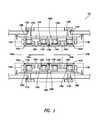
- FIG. 1is a cross-sectional, schematic view illustrating an exemplary sputtering system including two disks in corresponding sputtering locations, according to one embodiment.
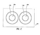
- FIG. 2is a top, schematic view illustrating one side of the sputtering system of FIG. 1 , according to one embodiment.
- FIG. 3is a perspective, schematic view illustrating an exemplary magnetic ring for use in the sputtering system of FIG. 1 , according to one embodiment.
- FIG. 4is a top, schematic view illustrating the exemplary magnetic ring of FIG. 3 , according to one embodiment.
- FIG. 5is a top, schematic view illustrating exemplary magnetic rings for use in the sputtering system of FIG. 1 , with shaded regions of lower relative magnetic strength, according to one embodiment.
- FIG. 6illustrates a flow chart for a method of manufacturing magnetic disks, according to one embodiment.
- the sputtering system 100includes a first sputtering assembly 102 a configured to sputter material onto a first disk 104 a and a second sputtering assembly 102 b configured to sputter material onto a second disk 104 b .
- the second sputtering assembly 102 bis positioned proximate the first sputtering assembly 102 a .
- the first sputtering assembly 102 amay include a first anode 106 a , a first cathode 108 a , a first target 110 a coupled to at least one of the first anode 106 a and the first cathode 108 a , and a first magnetic ring 112 a .
- the second sputtering assembly 102 bmay include a second anode 106 b , a second cathode 108 b , a second target 110 b coupled to at least one of the second anode 106 b and the second cathode 108 b , and a second magnetic ring 112 b .
- the first magnetic ring 112 aincludes a first region 114 a of lower relative magnetic strength positioned near the second magnetic ring 112 b
- the second magnetic ring 112 bincludes a second region 114 b of lower relative magnetic strength positioned near the first magnetic ring 112 a.
- the sputtering system 100may comprise any of a variety of systems configured to sputter materials in different environments.
- the sputtering system 100may be configured for RF, DC or pulsed-DC magnetron sputtering. In other embodiments, other sputtering methods may be implemented in the sputtering system 100 .
- the sputtering system 100includes two sputtering locations at which disks 104 a, b may be positioned within a sealed chamber. In other embodiments, the sputtering system 100 may include three or more sputtering locations for accommodating greater numbers of disks or other media.
- the sputtering system 100is configured to sputter materials onto a pair of magnetic disks 104 a, b , and the methods described herein will be described in terms of such a system.
- Such magnetic disks 104 a, bmay comprise the media used in conventional disk drives, and may include any of a variety of magnetic and non-magnetic materials deposited onto a substrate (e.g., glass or aluminum).
- a substratee.g., glass or aluminum
- the methods and components described hereinmay also be applied to and/or implemented in other sputtering systems, including, e.g., systems used to sputter materials onto optical and magneto-optical disks or onto differently shaped substrates used in other environments.
- the sputtering system 100may further comprise a third sputtering assembly 102 c configured to sputter material onto the first disk 104 a and a fourth sputtering assembly 102 d configured to sputter material onto the second disk 104 b .
- the third sputtering assembly 102 cis positioned opposite the first sputtering assembly 102 a
- the fourth sputtering assembly 102 dis positioned opposite the second sputtering assembly 102 b .
- the third sputtering assembly 102 amay include a third anode 106 c , a third cathode 108 c , a third target 110 c coupled to at least one of the third anode 106 c and the third cathode 108 c , and a third magnetic ring 112 c .
- the fourth sputtering assembly 102 dmay include a fourth anode 106 d , a fourth cathode 108 d , a fourth target 110 d coupled to at least one of the fourth anode 106 d and the fourth cathode 108 d , and a fourth magnetic ring 112 d .
- the third magnetic ring 112 cincludes a third region of lower relative magnetic strength positioned near the fourth magnetic ring 112 d
- the fourth magnetic ring 112 dincludes a fourth region of lower relative magnetic strength positioned near the third magnetic ring 112 c.
- the sputtering system 100may include substantially identical pairs of sputtering assemblies 102 a - d positioned opposite one another. As illustrated, these sputtering assemblies 102 a - d may be configured such that both sides of the first and second disks 104 a, b may be sputtered substantially concurrently. However, in other embodiments, the sputtering system 100 may be configured to sputter onto only one side of the disks 104 a, b at a time.
- the first sputtering assembly 102 aincludes a first anode 106 a and a first cathode 108 a .
- the first anode 106 ais positioned along a central axis of the first sputtering assembly 102 a .
- the first cathode 108 ais arranged peripherally about the first anode 106 a and is electrically coupled to the first target 110 a .
- positive ions created in the sputtering system 100are attracted to and bombard the surface of the first target 110 a , and material is thus ejected from the first target 110 a during the sputtering operation to be deposited onto the first disk 104 a .
- the first anode 106 ais generally circular when viewed from the top (as visible in FIG. 2 ), while the first cathode 108 a is generally disk-shaped.
- the geometry and polarity of these portions of the first sputtering assembly 102 amay be changed in different embodiments to achieve different sputtering characteristics.
- the first anode 106 amay be arranged peripherally about the first cathode 108 a and may be coupled to the first target 110 a.
- the first anode 106 ais electrically coupled to ground, and the first cathode 108 a is configured to reach an electrical potential of less than ⁇ 300 V.
- the first cathode 108 amay be kept at an electrical potential of approximately ⁇ 500 V.
- any of a variety of electrical potentialsmay be employed for the first anode 106 a and the first cathode 108 a to achieve the desired sputtering characteristics.
- the other anodes 106 b - d and cathodes 108 b - dmay be configured substantially similarly to the first anode 106 a and first cathode 108 a .
- the above description of the first anode 106 a and the first cathode 108 amay be applied equally to any of the anodes 106 b - d and cathodes 108 b - d .
- different geometries and electrical potentialsmay be used for the anodes 106 and cathodes 108 in the different sputtering assemblies 102 (e.g., in order to sputter different materials onto the disks 104 a, b ).
- the first and second targets 110 a, bmay comprise any of a variety of materials.
- the first and second targets 110 a, binclude magnetic alloys (e.g., Cobalt, Iron, Nickel), and may be used to sputter such magnetic alloys onto the first and second disks 104 a, b .
- the first and second targets 110 a, bmay include non-magnetic materials (e.g., Chrome, Carbon).
- Each of the targets 110 a, bmay be substantially disc-shaped in order to facilitate relatively homogeneous sputtering onto the disks 104 a, b .
- the geometry of the first and second targets 110 a, bmay be better understood with reference to FIG.
- the targets 110 a, beach have a diameter greater than that of the first and second disks 104 a, b .
- other geometries for the first and second targets 110 a, bmay be used to achieve different sputtering characteristics.
- the first target 110 amay be electrically coupled to the first cathode 108 a
- the second target 110 bmay be electrically coupled to the second cathode 108 b
- the first target 110 amay be received by and positioned in direct contact with the first cathode 108 a .
- the first target 110 amay be removed and replaced with a fresh target for additional sputtering.
- other structuresmay be used to electrically couple the first target 110 a to the first cathode 108 a . Similar structures may also be used to electrically couple the second target 110 b to the second cathode 108 b.
- the third and fourth targets 110 c, dmay be configured substantially similarly to the first and second targets 110 a, b .
- the above description of the first and second targets 110 a, bmay be applied equally to any of the targets 110 c, d .
- different geometries, materials and electrical coupling structuresmay be used for the targets 110 of the different sputtering assemblies 102 (e.g., in order to sputter different materials onto the disks 104 a, b ).
- the first sputtering assembly 102 ais positioned proximate the second sputtering assembly 102 b .
- the first target 110 a and the second target 110 bmay be positioned such that a central axis of the first target 110 a is spaced apart from a central axis of the second target 110 b by approximately 15 cm. Such spacing may be used, for example, when sputtering to 95 mm media used in magnetic disk drives.
- the first target 110 a and the second target 110 bmay be positioned closer or farther away, depending upon the size of the disks 104 a, b and overall geometry of the sputtering system 100 .
- the first cathode 108 amay be positioned less than 3 cm apart from the second cathode 108 b . Indeed, the first cathode 108 a may be positioned less than 1.5 cm apart from the second cathode 108 b .
- the sputtering system 100may further comprise a vacuum insulator 116 a positioned between the first cathode 108 a and the second cathode 108 b .
- the vacuum insulator 116 amay comprise TEFLON®, manufactured and sold by DuPont. In other embodiments, the vacuum insulator 116 a may comprise DELRIN®, also manufactured and sold by DuPont.
- the sputtering system 100may further comprise a first anode vacuum insulator 118 a positioned between the first anode 106 a and the first cathode 108 a , as well as a second anode vacuum insulator 118 b positioned between the second anode 106 b and the second cathode 108 b .
- the first and second anode vacuum insulators 118 a, bmay be formed from the same materials as the vacuum insulator 116 a.
- the geometry of and spacing between the first and second sputtering assemblies 102 a, bmay be similar to the geometry and spacing of the third and fourth sputtering assemblies 102 c, d .
- the above description of the first and second sputtering assemblies 102 a, bmay be applied equally to the third and fourth sputtering assemblies 102 c, d .
- the sputtering system 100may include a second vacuum insulator 116 b positioned between the third and fourth cathodes 108 c, d .
- the third and fourth sputtering assemblies 102 c, dmay also include respective third and fourth anode vacuum insulators 118 c, d.
- the sputtering system 100may further include a plurality of magnetic rings 112 a - d to enable magnetron sputtering.
- the geometry and configuration of these magnetic rings 112 a - dmay be better understood with reference to FIGS. 3-5 , which illustrate exemplary magnetic rings 112 separated from the other components of the sputtering system 100 .
- the first magnetic ring 112 aincludes a first plurality of permanent magnets 120 a
- the second magnetic ring 112 bincludes a second plurality of permanent magnets 120 b (as illustrated in FIGS. 3-5 ).
- These permanent magnets 120 a, bmay be arranged to form substantially continuous magnetic rings 112 a, b . That is, in one embodiment, each of the first plurality of permanent magnets 120 a may be in mating contact with adjacent permanent magnets 120 a to either side, as shown in FIG. 5 . In other embodiments, the first magnetic ring 112 a may not be continuous but may include one or more gaps in the ring, where the first plurality of permanent magnets 120 a are not in close contact.
- the first and second magnetic rings 112 a, bneed not be perfectly circular.
- each of the magnetic rings 112 a, bmay be generally elliptical.
- the first plurality of permanent magnets 120 amay be affixed to a first carrying plate 122 a to form the first magnetic ring 112 a .
- the second plurality of permanent magnets 120 bmay be affixed to a second carrying plate 122 b to form the second magnetic ring 112 b .
- the permanent magnets 120 a, bmay be affixed to the carrying plates 122 a, b using adhesive or other mechanical fasteners.
- the first carrying plates 122 amay be omitted, and the first plurality of permanent magnets 120 a may be affixed one to the other to form the first magnetic ring 112 a .
- Other structures for forming the magnetic rings 112 a, bmay also be used.
- the first and second plurality of permanent magnets 120 a, bmay comprise any of a variety of magnetic materials.
- the permanent magnets 120 a, bcomprise a magnetic alloy including Neodymium, Iron and Boron in any of a variety of ratios.
- a magnetic alloy of Samarium and Cobaltmay be used.
- first and second magnetic rings 112 a, bmay be formed from other magnetic structures.
- a unitary ring of permanent magnetic materialis used to form each of the first and second magnetic rings 112 a, b .
- the first and second magnetic rings 112 a, bmay each comprise one or more electromagnets.
- the first and second magnetic rings 112 a, binclude regions 114 a, b of lower relative magnetic strength. If the first and second magnetic rings 112 a, b comprise corresponding pluralities of permanent magnets 120 a, b , the first region 114 a of lower relative magnetic strength may include at least one permanent magnet 124 a (shaded in FIG. 5 ) that is weaker than other magnets of the first plurality of permanent magnets 120 a . Similarly, the second region 114 b of lower relative magnetic strength may include at least one permanent magnet 124 b that is weaker than other magnets of the second plurality of magnets 120 b .
- the magnetic field of the first magnetic ring 112 amight be asymmetrical, distorted by a bucking effect caused by the interaction between magnetic fields generated by the first and second magnetic rings 112 a, b .
- the magnetic field of the second magnetic ring 112 bmight also be asymmetrical.
- the weakened regions 114 a, bmay be configured to compensate for the bucking effect, and allow the magnetic fields of each of the magnetic rings 112 a, b to be made substantially symmetrical.
- the weaker permanent magnets 124 a, bmay be less than 10% weaker than the other permanent magnets 120 a, b . In another embodiment, the weaker permanent magnets 124 a, b may be approximately 5% weaker than the other permanent magnets 120 a, b . In still another embodiment, the weaker permanent magnets 124 a, b may be at least 1% weaker than the other permanent magnets 120 a, b . Although three permanent magnets 124 a, b of each magnetic ring 112 a, b are illustrated as weaker in FIG. 5 , more or fewer permanent magnets may be made weaker in different embodiments to achieve the desired magnetic fields.
- regions of the magnetic rings 112 a, bmay be shunted in order to modify the shape of the magnetic fields generated by the magnetic rings 112 a, b and thereby decrease the effective magnetic strength of such regions 114 a, b .
- additional, repelling magnetsmay be arranged relative to the magnetic rings 112 a, b in order to modify the shape of the magnetic fields generated by the magnetic rings 112 a, b .
- a location or size of one or more of the permanent magnets 120 a, bmay be modified in order to achieve a lower relative magnetic strength.
- the first sputtering assembly 102 afurther includes a first inner magnetic ring 126 a concentric with and positioned within the first magnetic ring 112 a
- the second sputtering assembly 102 bincludes a second inner magnetic ring 126 b concentric with and positioned within the second magnetic ring 112 b
- These pairs of magnetic rings 112 a, b , 126 a, bmay be configured to create magnetic fields that improve efficiency during magnetron sputtering.
- the inner magnetic rings 126 a, bcomprise permanent magnets configured similarly to the permanent magnets 120 a, b that form the magnetic rings 112 a, b .
- different magnetic structuresmay be used to form the inner magnetic rings 126 a, b .
- the first magnetic ring 112 ais oriented such that a north pole of the first magnetic ring 112 a is configured to face the first disk 104 a
- the first inner magnetic ring 126 ais oriented such that a south pole is configured to face the first disk 104 a
- the second magnetic ring 112 b and the second inner magnetic ring 126 bmay be oriented similarly.
- alternative orientations for the magnetic rings 112 a, b , 126 a, bmay be employed.
- the other magnetic rings 112 c, d and inner magnetic rings 126 c, dmay be configured substantially similarly to the first and second magnetic rings 112 a, b and first and second inner magnetic rings 126 a, b .
- the above description of the first and second magnetic rings 112 a, b and the first and second inner magnetic rings 126 a, bmay be applied equally to the other magnetic rings 112 c, d and inner magnetic rings 126 c, d .
- different geometries and structuresmay be used for the magnetic rings 112 c, d and inner magnetic rings 126 c, d in the other sputtering assemblies 102 c, d.
- FIG. 6illustrates a flow chart for a method 600 of manufacturing magnetic disks, according to one illustrated embodiment.
- This method 600will be discussed in the context of the sputtering system 100 of FIGS. 1-5 .
- the acts disclosed hereinmay be executed using any sputtering system, in accordance with the described method.
- the acts of method 600may also be carried out in other contexts. For example, acts of method 600 may be carried out to manufacture optical or magneto-optical disks.
- many of the acts comprising the method 600may be orchestrated by a processor according to an automatic manufacturing algorithm, based at least in part on computer-readable instructions stored in computer-readable memory and executable by the processor.
- a manual implementation of one or more acts of the method 600may also be employed.
- a sputtering system 100has a first target 110 a and a first magnetic ring 112 a associated with the first target 110 a , and a second target 110 b and a second magnetic ring 112 b associated with the second target 110 b .
- the first magnetic ring 112 aincludes a first region 114 a of lower relative magnetic strength positioned near the second magnetic ring 112 b
- the second magnetic ring 112 bincludes a second region 114 b of lower relative magnetic strength positioned near the first magnetic ring 112 a .
- the sputtering system 100may comprise one among a number of sputtering systems used in the manufacture of magnetic disks 104 a, b.
- a first disk 104 ais positioned at a first sputtering location 128 a within the sputtering system 100 , the first sputtering location 128 a associated with the first target 110 a .
- a second disk 104 bis positioned at a second sputtering location 128 b within the sputtering system 100 , the second sputtering locations 128 b associated with the second target 110 b , the second sputtering location 128 b proximate the first sputtering location 128 a .
- first and second disks 104 a, bmay be positioned at these sputtering locations 128 a, b using one or more movable disk carriers.
- first and second disks 104 a, bmay be loaded onto respective holders at the sputtering locations 128 a, b using a robotic arm.
- other mechanismsmay be used to position the first and second disks 104 a, b at the sputtering locations 128 a, b .
- Acts 604 and 606may be carried out substantially concurrently or at different times.
- a first electrical potential differenceis generated between a first anode 106 a and a first cathode 108 a associated with the first sputtering location 128 a
- a second electrical potential differenceis generated between a second anode 106 b and a second cathode 108 b associated with the second sputtering location 128 b
- generating the first electrical potential differencemay include bringing the first anode 106 a to a ground potential and bringing the first cathode 108 a to a potential of less than ⁇ 300V.
- the second electrical potential differencemay be generated similarly. In other embodiments, different electrical potential differences may be generated.
- the sputtering system 100may enable increased throughput by sputtering to multiple disks concurrently.
- the method 600may further comprise concurrently sputtering material from a third target 110 c onto an opposite surface of the first disk 104 a , and from a fourth target 110 d onto an opposite surface of the second disk 104 b . These acts may be executed concurrently with act 612 .
- the method 600may further comprise eroding a first approximately circular race track pattern in the first target 110 a and a second approximately circular race track pattern in the second target 110 b while concurrently sputtering. It may be understood that these approximately circular race track patterns are indicative of the pattern of material that is ejected from the targets 110 a, b during the sputtering process. By keeping the race track patterns approximately circular (as opposed to elliptical), a more even deposition of material across the disks 104 a, b may be possible. In one embodiment, the approximately circular race track patterns may be formed such that, even if slightly elliptical, the major axis is not more than 20% larger than the minor axis.
- the approximately circular race track patternsmay be formed such that, even if slightly elliptical, the major axis is not more than 10% larger than the minor axis. In other embodiments, even tighter tolerances may be required.
- the approximately circular race track patternsmay be achieved based at least in part on the regions 114 a, b of lower relative magnetic strength, which may compensate for the bucking effect between the magnetic rings 112 a, b , and allow the effective magnetic fields formed in part by each of the magnetic rings 112 a, b to be substantially symmetrical about their respective central axes.
Landscapes
- Chemical & Material Sciences (AREA)
- Engineering & Computer Science (AREA)
- Chemical Kinetics & Catalysis (AREA)
- Materials Engineering (AREA)
- Mechanical Engineering (AREA)
- Metallurgy (AREA)
- Organic Chemistry (AREA)
- Physics & Mathematics (AREA)
- Plasma & Fusion (AREA)
- Analytical Chemistry (AREA)
- Manufacturing Of Magnetic Record Carriers (AREA)
- Physical Vapour Deposition (AREA)
Abstract
Description
Claims (14)
Priority Applications (1)
| Application Number | Priority Date | Filing Date | Title |
|---|---|---|---|
| US13/409,050US8658003B1 (en) | 2009-02-10 | 2012-02-29 | Dual position DC magnetron assembly |
Applications Claiming Priority (2)
| Application Number | Priority Date | Filing Date | Title |
|---|---|---|---|
| US12/368,951US8137517B1 (en) | 2009-02-10 | 2009-02-10 | Dual position DC magnetron assembly |
| US13/409,050US8658003B1 (en) | 2009-02-10 | 2012-02-29 | Dual position DC magnetron assembly |
Related Parent Applications (1)
| Application Number | Title | Priority Date | Filing Date |
|---|---|---|---|
| US12/368,951DivisionUS8137517B1 (en) | 2009-02-10 | 2009-02-10 | Dual position DC magnetron assembly |
Publications (1)
| Publication Number | Publication Date |
|---|---|
| US8658003B1true US8658003B1 (en) | 2014-02-25 |
Family
ID=45813293
Family Applications (2)
| Application Number | Title | Priority Date | Filing Date |
|---|---|---|---|
| US12/368,951Expired - Fee RelatedUS8137517B1 (en) | 2009-02-10 | 2009-02-10 | Dual position DC magnetron assembly |
| US13/409,050Expired - Fee RelatedUS8658003B1 (en) | 2009-02-10 | 2012-02-29 | Dual position DC magnetron assembly |
Family Applications Before (1)
| Application Number | Title | Priority Date | Filing Date |
|---|---|---|---|
| US12/368,951Expired - Fee RelatedUS8137517B1 (en) | 2009-02-10 | 2009-02-10 | Dual position DC magnetron assembly |
Country Status (1)
| Country | Link |
|---|---|
| US (2) | US8137517B1 (en) |
Cited By (67)
| Publication number | Priority date | Publication date | Assignee | Title |
|---|---|---|---|---|
| US20110026162A1 (en)* | 2008-03-30 | 2011-02-03 | Hoya Corporation | Magnetic disk and method of manufacturing the same |
| US8828566B2 (en) | 2010-05-21 | 2014-09-09 | Wd Media (Singapore) Pte. Ltd. | Perpendicular magnetic recording disc |
| US8859118B2 (en) | 2010-01-08 | 2014-10-14 | Wd Media (Singapore) Pte. Ltd. | Perpendicular magnetic recording medium |
| US8867322B1 (en) | 2013-05-07 | 2014-10-21 | WD Media, LLC | Systems and methods for providing thermal barrier bilayers for heat assisted magnetic recording media |
| US8877359B2 (en) | 2008-12-05 | 2014-11-04 | Wd Media (Singapore) Pte. Ltd. | Magnetic disk and method for manufacturing same |
| US8908315B2 (en) | 2010-03-29 | 2014-12-09 | Wd Media (Singapore) Pte. Ltd. | Evaluation method of magnetic disk, manufacturing method of magnetic disk, and magnetic disk |
| US8941950B2 (en) | 2012-05-23 | 2015-01-27 | WD Media, LLC | Underlayers for heat assisted magnetic recording (HAMR) media |
| US8947987B1 (en) | 2013-05-03 | 2015-02-03 | WD Media, LLC | Systems and methods for providing capping layers for heat assisted magnetic recording media |
| US8951651B2 (en) | 2010-05-28 | 2015-02-10 | Wd Media (Singapore) Pte. Ltd. | Perpendicular magnetic recording disk |
| US8980076B1 (en) | 2009-05-26 | 2015-03-17 | WD Media, LLC | Electro-deposited passivation coatings for patterned media |
| US8995078B1 (en) | 2014-09-25 | 2015-03-31 | WD Media, LLC | Method of testing a head for contamination |
| US8993134B2 (en) | 2012-06-29 | 2015-03-31 | Western Digital Technologies, Inc. | Electrically conductive underlayer to grow FePt granular media with (001) texture on glass substrates |
| US9001630B1 (en) | 2011-03-08 | 2015-04-07 | Western Digital Technologies, Inc. | Energy assisted magnetic recording medium capable of suppressing high DC readback noise |
| US9025264B1 (en) | 2011-03-10 | 2015-05-05 | WD Media, LLC | Methods for measuring media performance associated with adjacent track interference |
| US9028985B2 (en) | 2011-03-31 | 2015-05-12 | WD Media, LLC | Recording media with multiple exchange coupled magnetic layers |
| US9029308B1 (en) | 2012-03-28 | 2015-05-12 | WD Media, LLC | Low foam media cleaning detergent |
| US9034492B1 (en) | 2013-01-11 | 2015-05-19 | WD Media, LLC | Systems and methods for controlling damping of magnetic media for heat assisted magnetic recording |
| US9042053B1 (en) | 2014-06-24 | 2015-05-26 | WD Media, LLC | Thermally stabilized perpendicular magnetic recording medium |
| US9047903B2 (en) | 2008-03-26 | 2015-06-02 | Wd Media (Singapore) Pte. Ltd. | Perpendicular magnetic recording medium and process for manufacture thereof |
| US9047880B1 (en) | 2011-12-20 | 2015-06-02 | WD Media, LLC | Heat assisted magnetic recording method for media having moment keeper layer |
| US9064521B1 (en) | 2011-03-25 | 2015-06-23 | WD Media, LLC | Manufacturing of hard masks for patterning magnetic media |
| US9082447B1 (en) | 2014-09-22 | 2015-07-14 | WD Media, LLC | Determining storage media substrate material type |
| US9093100B2 (en) | 2008-03-17 | 2015-07-28 | Wd Media (Singapore) Pte. Ltd. | Magnetic recording medium including tailored exchange coupling layer and manufacturing method of the same |
| US9093122B1 (en) | 2013-04-05 | 2015-07-28 | WD Media, LLC | Systems and methods for improving accuracy of test measurements involving aggressor tracks written to disks of hard disk drives |
| US9142241B2 (en) | 2009-03-30 | 2015-09-22 | Wd Media (Singapore) Pte. Ltd. | Perpendicular magnetic recording medium and method of manufacturing the same |
| US9153268B1 (en) | 2013-02-19 | 2015-10-06 | WD Media, LLC | Lubricants comprising fluorinated graphene nanoribbons for magnetic recording media structure |
| US9159350B1 (en) | 2014-07-02 | 2015-10-13 | WD Media, LLC | High damping cap layer for magnetic recording media |
| US9177585B1 (en) | 2013-10-23 | 2015-11-03 | WD Media, LLC | Magnetic media capable of improving magnetic properties and thermal management for heat-assisted magnetic recording |
| US9177586B2 (en) | 2008-09-30 | 2015-11-03 | WD Media (Singapore), LLC | Magnetic disk and manufacturing method thereof |
| US9183867B1 (en) | 2013-02-21 | 2015-11-10 | WD Media, LLC | Systems and methods for forming implanted capping layers in magnetic media for magnetic recording |
| US9190094B2 (en) | 2013-04-04 | 2015-11-17 | Western Digital (Fremont) | Perpendicular recording media with grain isolation initiation layer and exchange breaking layer for signal-to-noise ratio enhancement |
| US9196283B1 (en) | 2013-03-13 | 2015-11-24 | Western Digital (Fremont), Llc | Method for providing a magnetic recording transducer using a chemical buffer |
| US9218850B1 (en) | 2014-12-23 | 2015-12-22 | WD Media, LLC | Exchange break layer for heat-assisted magnetic recording media |
| US9227324B1 (en) | 2014-09-25 | 2016-01-05 | WD Media, LLC | Mandrel for substrate transport system with notch |
| US9240204B2 (en) | 2010-05-21 | 2016-01-19 | Wd Media (Singapore) Pte. Ltd. | Perpendicular magnetic recording disc |
| US9257134B1 (en) | 2014-12-24 | 2016-02-09 | Western Digital Technologies, Inc. | Allowing fast data zone switches on data storage devices |
| US9269480B1 (en) | 2012-03-30 | 2016-02-23 | WD Media, LLC | Systems and methods for forming magnetic recording media with improved grain columnar growth for energy assisted magnetic recording |
| US9275669B1 (en) | 2015-03-31 | 2016-03-01 | WD Media, LLC | TbFeCo in PMR media for SNR improvement |
| US9280998B1 (en) | 2015-03-30 | 2016-03-08 | WD Media, LLC | Acidic post-sputter wash for magnetic recording media |
| US9296082B1 (en) | 2013-06-11 | 2016-03-29 | WD Media, LLC | Disk buffing apparatus with abrasive tape loading pad having a vibration absorbing layer |
| US9330685B1 (en) | 2009-11-06 | 2016-05-03 | WD Media, LLC | Press system for nano-imprinting of recording media with a two step pressing method |
| US9339978B1 (en) | 2009-11-06 | 2016-05-17 | WD Media, LLC | Press system with interleaved embossing foil holders for nano-imprinting of recording media |
| US9349404B2 (en) | 2010-05-28 | 2016-05-24 | Wd Media (Singapore) Pte. Ltd | Perpendicular magnetic recording disc |
| US9382496B1 (en) | 2013-12-19 | 2016-07-05 | Western Digital Technologies, Inc. | Lubricants with high thermal stability for heat-assisted magnetic recording |
| US9389135B2 (en) | 2013-09-26 | 2016-07-12 | WD Media, LLC | Systems and methods for calibrating a load cell of a disk burnishing machine |
| US9401300B1 (en) | 2014-12-18 | 2016-07-26 | WD Media, LLC | Media substrate gripper including a plurality of snap-fit fingers |
| US9406329B1 (en) | 2015-11-30 | 2016-08-02 | WD Media, LLC | HAMR media structure with intermediate layer underlying a magnetic recording layer having multiple sublayers |
| US9406330B1 (en) | 2013-06-19 | 2016-08-02 | WD Media, LLC | Method for HDD disk defect source detection |
| US9431045B1 (en) | 2014-04-25 | 2016-08-30 | WD Media, LLC | Magnetic seed layer used with an unbalanced soft underlayer |
| US9447368B1 (en) | 2014-02-18 | 2016-09-20 | WD Media, LLC | Detergent composition with low foam and high nickel solubility |
| US9449633B1 (en) | 2014-11-06 | 2016-09-20 | WD Media, LLC | Smooth structures for heat-assisted magnetic recording media |
| US9472227B2 (en) | 2010-06-22 | 2016-10-18 | Wd Media (Singapore) Pte. Ltd. | Perpendicular magnetic recording media and methods for producing the same |
| US9542968B1 (en) | 2010-08-20 | 2017-01-10 | WD Media, LLC | Single layer small grain size FePT:C film for heat assisted magnetic recording media |
| US9558778B2 (en) | 2009-03-28 | 2017-01-31 | Wd Media (Singapore) Pte. Ltd. | Lubricant compound for magnetic disk and magnetic disk |
| US9581510B1 (en) | 2013-12-16 | 2017-02-28 | Western Digital Technologies, Inc. | Sputter chamber pressure gauge with vibration absorber |
| US9607646B2 (en) | 2013-07-30 | 2017-03-28 | WD Media, LLC | Hard disk double lubrication layer |
| US9685184B1 (en) | 2014-09-25 | 2017-06-20 | WD Media, LLC | NiFeX-based seed layer for magnetic recording media |
| US9818442B2 (en) | 2014-12-01 | 2017-11-14 | WD Media, LLC | Magnetic media having improved magnetic grain size distribution and intergranular segregation |
| US9822441B2 (en) | 2015-03-31 | 2017-11-21 | WD Media, LLC | Iridium underlayer for heat assisted magnetic recording media |
| US9824711B1 (en) | 2014-02-14 | 2017-11-21 | WD Media, LLC | Soft underlayer for heat assisted magnetic recording media |
| US9990940B1 (en) | 2014-12-30 | 2018-06-05 | WD Media, LLC | Seed structure for perpendicular magnetic recording media |
| US10054363B2 (en) | 2014-08-15 | 2018-08-21 | WD Media, LLC | Method and apparatus for cryogenic dynamic cooling |
| US10083715B2 (en) | 2010-05-28 | 2018-09-25 | WD Media (Singapore) Pte.Ltd. | Method of manufacturing a perpendicular magnetic disc |
| US10115428B1 (en) | 2013-02-15 | 2018-10-30 | Wd Media, Inc. | HAMR media structure having an anisotropic thermal barrier layer |
| US10121506B1 (en) | 2015-12-29 | 2018-11-06 | WD Media, LLC | Magnetic-recording medium including a carbon overcoat implanted with nitrogen and hydrogen |
| US10236026B1 (en) | 2015-11-06 | 2019-03-19 | WD Media, LLC | Thermal barrier layers and seed layers for control of thermal and structural properties of HAMR media |
| US11074934B1 (en) | 2015-09-25 | 2021-07-27 | Western Digital Technologies, Inc. | Heat assisted magnetic recording (HAMR) media with Curie temperature reduction layer |
Families Citing this family (4)
| Publication number | Priority date | Publication date | Assignee | Title |
|---|---|---|---|---|
| US8137517B1 (en) | 2009-02-10 | 2012-03-20 | Wd Media, Inc. | Dual position DC magnetron assembly |
| US8685214B1 (en) | 2011-09-30 | 2014-04-01 | WD Media, LLC | Magnetic shunting pads for optimizing target erosion in sputtering processes |
| US8674327B1 (en) | 2012-05-10 | 2014-03-18 | WD Media, LLC | Systems and methods for uniformly implanting materials on substrates using directed magnetic fields |
| US9812305B2 (en)* | 2015-04-27 | 2017-11-07 | Advanced Energy Industries, Inc. | Rate enhanced pulsed DC sputtering system |
Citations (49)
| Publication number | Priority date | Publication date | Assignee | Title |
|---|---|---|---|---|
| US4597847A (en) | 1984-10-09 | 1986-07-01 | Iodep, Inc. | Non-magnetic sputtering target |
| US4604180A (en) | 1984-01-20 | 1986-08-05 | Anelva Corporation | Target assembly capable of attaining a high step coverage ratio in a magnetron-type sputtering device |
| US4647361A (en) | 1985-09-03 | 1987-03-03 | International Business Machines Corporation | Sputtering apparatus |
| US4714536A (en) | 1985-08-26 | 1987-12-22 | Varian Associates, Inc. | Planar magnetron sputtering device with combined circumferential and radial movement of magnetic fields |
| JPH01263912A (en) | 1988-04-13 | 1989-10-20 | Matsushita Electric Ind Co Ltd | Magnetic recording medium |
| US4995958A (en) | 1989-05-22 | 1991-02-26 | Varian Associates, Inc. | Sputtering apparatus with a rotating magnet array having a geometry for specified target erosion profile |
| US5126029A (en) | 1990-12-27 | 1992-06-30 | Intel Corporation | Apparatus and method for achieving via step coverage symmetry |
| US5174880A (en) | 1991-08-05 | 1992-12-29 | Hmt Technology Corporation | Magnetron sputter gun target assembly with distributed magnetic field |
| US5200049A (en) | 1990-08-10 | 1993-04-06 | Viratec Thin Films, Inc. | Cantilever mount for rotating cylindrical magnetrons |
| US5215638A (en) | 1991-08-08 | 1993-06-01 | Leybold Aktiengesellschaft | Rotating magnetron cathode and method for the use thereof |
| US5252194A (en) | 1990-01-26 | 1993-10-12 | Varian Associates, Inc. | Rotating sputtering apparatus for selected erosion |
| US5477743A (en) | 1993-09-03 | 1995-12-26 | Yugen Kaisha Sozoan | Two dimensional drive system |
| US5512150A (en) | 1995-03-09 | 1996-04-30 | Hmt Technology Corporation | Target assembly having inner and outer targets |
| US5554249A (en) | 1994-02-28 | 1996-09-10 | Tokyo Electron Limited | Magnetron plasma processing system |
| US5645699A (en) | 1994-09-06 | 1997-07-08 | The Boc Group, Inc. | Dual cylindrical target magnetron with multiple anodes |
| JPH09219020A (en) | 1996-02-14 | 1997-08-19 | Hitachi Ltd | Magnetic recording medium and method of manufacturing the same |
| US5685959A (en) | 1996-10-25 | 1997-11-11 | Hmt Technology Corporation | Cathode assembly having rotating magnetic-field shunt and method of making magnetic recording media |
| US5736020A (en) | 1995-04-24 | 1998-04-07 | Hmt Technology Corporation | Target assembly for use in forming an overcoat in a magnetic recording medium |
| US5762766A (en) | 1995-11-20 | 1998-06-09 | Anelva Corporation | Method for depositing magnetic film on both substrate surfaces and mechanism for performing same |
| US5795451A (en) | 1997-06-12 | 1998-08-18 | Read-Rite Corporation | Sputtering apparatus with a rotating magnet array |
| US5879523A (en) | 1997-09-29 | 1999-03-09 | Applied Materials, Inc. | Ceramic coated metallic insulator particularly useful in a plasma sputter reactor |
| US5968328A (en) | 1996-12-11 | 1999-10-19 | Leybold Systems Gmbh | Device for sputter deposition of thin layers on flat substrates |
| US6024843A (en) | 1989-05-22 | 2000-02-15 | Novellus Systems, Inc. | Sputtering apparatus with a rotating magnet array having a geometry for specified target erosion profile |
| US6033483A (en) | 1994-06-30 | 2000-03-07 | Applied Materials, Inc. | Electrically insulating sealing structure and its method of use in a high vacuum physical vapor deposition apparatus |
| US6139695A (en) | 1995-08-07 | 2000-10-31 | Akashic Memories Corporation | Modular deposition system having batch processing and serial thin film deposition |
| US6228236B1 (en) | 1999-10-22 | 2001-05-08 | Applied Materials, Inc. | Sputter magnetron having two rotation diameters |
| US6258217B1 (en) | 1999-09-29 | 2001-07-10 | Plasma-Therm, Inc. | Rotating magnet array and sputter source |
| US6277250B1 (en) | 2000-10-19 | 2001-08-21 | Tokyo Electron Limited | Dual cathode arrangement for physical vapor deposition of materials onto a round substrate with high aspect ratio features |
| US6312798B1 (en) | 1998-09-25 | 2001-11-06 | Seagate Technology Llc | Magnetic recording medium having a nitrogen-doped hydrogenated carbon protective overcoat |
| US6322679B1 (en) | 1997-11-19 | 2001-11-27 | Sinvaco N.V. | Planar magnetron with moving magnet assembly |
| US6365010B1 (en) | 1998-11-06 | 2002-04-02 | Scivac | Sputtering apparatus and process for high rate coatings |
| US6406599B1 (en) | 2000-11-01 | 2002-06-18 | Applied Materials, Inc. | Magnetron with a rotating center magnet for a vault shaped sputtering target |
| US6413383B1 (en) | 1999-10-08 | 2002-07-02 | Applied Materials, Inc. | Method for igniting a plasma in a sputter reactor |
| US6413382B1 (en) | 2000-11-03 | 2002-07-02 | Applied Materials, Inc. | Pulsed sputtering with a small rotating magnetron |
| US6610184B2 (en) | 2001-11-14 | 2003-08-26 | Applied Materials, Inc. | Magnet array in conjunction with rotating magnetron for plasma sputtering |
| US20030209423A1 (en) | 2001-03-27 | 2003-11-13 | Christie David J. | System for driving multiple magnetrons with multiple phase ac |
| US6706363B2 (en) | 2001-02-02 | 2004-03-16 | Hitachi, Ltd. | Magnetic recording medium, its production method and magnetic storage device using the medium |
| US6841050B2 (en) | 2002-05-21 | 2005-01-11 | Applied Materials, Inc. | Small planetary magnetron |
| US6852202B2 (en) | 2002-05-21 | 2005-02-08 | Applied Materials, Inc. | Small epicyclic magnetron with controlled radial sputtering profile |
| US20050103620A1 (en) | 2003-11-19 | 2005-05-19 | Zond, Inc. | Plasma source with segmented magnetron cathode |
| US20050236267A1 (en) | 2004-04-27 | 2005-10-27 | Paul Rich | Methods and apparatus for controlling rotating magnetic fields |
| US7018515B2 (en) | 2004-03-24 | 2006-03-28 | Applied Materials, Inc. | Selectable dual position magnetron |
| US20060081466A1 (en) | 2004-10-15 | 2006-04-20 | Makoto Nagashima | High uniformity 1-D multiple magnet magnetron source |
| US7119489B2 (en) | 2002-03-14 | 2006-10-10 | Samsung Electronics Co., Ltd. | Rotation-magnetron-in-magnetron (RMIM) electrode, method of manufacturing the RMIM electrode, and sputtering apparatus including the RMIM electrode |
| US7182843B2 (en) | 2003-11-05 | 2007-02-27 | Dexter Magnetic Technologies, Inc. | Rotating sputtering magnetron |
| US20070227881A1 (en) | 2006-03-29 | 2007-10-04 | Applied Materials Gmbh & Co. Kg | Rotary vacuum feedthrough for rotatable magnetrons |
| US20080060938A1 (en) | 2005-09-14 | 2008-03-13 | Applied Materials, Inc. | Coaxial Shafts for Radial Positioning of Rotating Magnetron |
| US7504006B2 (en) | 2002-08-01 | 2009-03-17 | Applied Materials, Inc. | Self-ionized and capacitively-coupled plasma for sputtering and resputtering |
| US8137517B1 (en) | 2009-02-10 | 2012-03-20 | Wd Media, Inc. | Dual position DC magnetron assembly |
- 2009
- 2009-02-10USUS12/368,951patent/US8137517B1/ennot_activeExpired - Fee Related
- 2012
- 2012-02-29USUS13/409,050patent/US8658003B1/ennot_activeExpired - Fee Related
Patent Citations (51)
| Publication number | Priority date | Publication date | Assignee | Title |
|---|---|---|---|---|
| US4604180A (en) | 1984-01-20 | 1986-08-05 | Anelva Corporation | Target assembly capable of attaining a high step coverage ratio in a magnetron-type sputtering device |
| US4597847A (en) | 1984-10-09 | 1986-07-01 | Iodep, Inc. | Non-magnetic sputtering target |
| US4714536A (en) | 1985-08-26 | 1987-12-22 | Varian Associates, Inc. | Planar magnetron sputtering device with combined circumferential and radial movement of magnetic fields |
| US4647361A (en) | 1985-09-03 | 1987-03-03 | International Business Machines Corporation | Sputtering apparatus |
| JPH01263912A (en) | 1988-04-13 | 1989-10-20 | Matsushita Electric Ind Co Ltd | Magnetic recording medium |
| US6024843A (en) | 1989-05-22 | 2000-02-15 | Novellus Systems, Inc. | Sputtering apparatus with a rotating magnet array having a geometry for specified target erosion profile |
| US4995958A (en) | 1989-05-22 | 1991-02-26 | Varian Associates, Inc. | Sputtering apparatus with a rotating magnet array having a geometry for specified target erosion profile |
| US5252194A (en) | 1990-01-26 | 1993-10-12 | Varian Associates, Inc. | Rotating sputtering apparatus for selected erosion |
| US5200049A (en) | 1990-08-10 | 1993-04-06 | Viratec Thin Films, Inc. | Cantilever mount for rotating cylindrical magnetrons |
| US5126029A (en) | 1990-12-27 | 1992-06-30 | Intel Corporation | Apparatus and method for achieving via step coverage symmetry |
| US5174880A (en) | 1991-08-05 | 1992-12-29 | Hmt Technology Corporation | Magnetron sputter gun target assembly with distributed magnetic field |
| US5215638A (en) | 1991-08-08 | 1993-06-01 | Leybold Aktiengesellschaft | Rotating magnetron cathode and method for the use thereof |
| US5477743A (en) | 1993-09-03 | 1995-12-26 | Yugen Kaisha Sozoan | Two dimensional drive system |
| US5554249A (en) | 1994-02-28 | 1996-09-10 | Tokyo Electron Limited | Magnetron plasma processing system |
| US6033483A (en) | 1994-06-30 | 2000-03-07 | Applied Materials, Inc. | Electrically insulating sealing structure and its method of use in a high vacuum physical vapor deposition apparatus |
| US5645699A (en) | 1994-09-06 | 1997-07-08 | The Boc Group, Inc. | Dual cylindrical target magnetron with multiple anodes |
| US5512150A (en) | 1995-03-09 | 1996-04-30 | Hmt Technology Corporation | Target assembly having inner and outer targets |
| US5736020A (en) | 1995-04-24 | 1998-04-07 | Hmt Technology Corporation | Target assembly for use in forming an overcoat in a magnetic recording medium |
| US6139695A (en) | 1995-08-07 | 2000-10-31 | Akashic Memories Corporation | Modular deposition system having batch processing and serial thin film deposition |
| US5762766A (en) | 1995-11-20 | 1998-06-09 | Anelva Corporation | Method for depositing magnetic film on both substrate surfaces and mechanism for performing same |
| JPH09219020A (en) | 1996-02-14 | 1997-08-19 | Hitachi Ltd | Magnetic recording medium and method of manufacturing the same |
| US5685959A (en) | 1996-10-25 | 1997-11-11 | Hmt Technology Corporation | Cathode assembly having rotating magnetic-field shunt and method of making magnetic recording media |
| US5968328A (en) | 1996-12-11 | 1999-10-19 | Leybold Systems Gmbh | Device for sputter deposition of thin layers on flat substrates |
| US5795451A (en) | 1997-06-12 | 1998-08-18 | Read-Rite Corporation | Sputtering apparatus with a rotating magnet array |
| US5879523A (en) | 1997-09-29 | 1999-03-09 | Applied Materials, Inc. | Ceramic coated metallic insulator particularly useful in a plasma sputter reactor |
| US6322679B1 (en) | 1997-11-19 | 2001-11-27 | Sinvaco N.V. | Planar magnetron with moving magnet assembly |
| US6312798B1 (en) | 1998-09-25 | 2001-11-06 | Seagate Technology Llc | Magnetic recording medium having a nitrogen-doped hydrogenated carbon protective overcoat |
| US6365010B1 (en) | 1998-11-06 | 2002-04-02 | Scivac | Sputtering apparatus and process for high rate coatings |
| US6258217B1 (en) | 1999-09-29 | 2001-07-10 | Plasma-Therm, Inc. | Rotating magnet array and sputter source |
| US6413383B1 (en) | 1999-10-08 | 2002-07-02 | Applied Materials, Inc. | Method for igniting a plasma in a sputter reactor |
| US6228236B1 (en) | 1999-10-22 | 2001-05-08 | Applied Materials, Inc. | Sputter magnetron having two rotation diameters |
| US6277250B1 (en) | 2000-10-19 | 2001-08-21 | Tokyo Electron Limited | Dual cathode arrangement for physical vapor deposition of materials onto a round substrate with high aspect ratio features |
| US6406599B1 (en) | 2000-11-01 | 2002-06-18 | Applied Materials, Inc. | Magnetron with a rotating center magnet for a vault shaped sputtering target |
| US6413382B1 (en) | 2000-11-03 | 2002-07-02 | Applied Materials, Inc. | Pulsed sputtering with a small rotating magnetron |
| US6706363B2 (en) | 2001-02-02 | 2004-03-16 | Hitachi, Ltd. | Magnetic recording medium, its production method and magnetic storage device using the medium |
| US20030209423A1 (en) | 2001-03-27 | 2003-11-13 | Christie David J. | System for driving multiple magnetrons with multiple phase ac |
| US6610184B2 (en) | 2001-11-14 | 2003-08-26 | Applied Materials, Inc. | Magnet array in conjunction with rotating magnetron for plasma sputtering |
| US7208878B2 (en) | 2002-03-14 | 2007-04-24 | Samsung Electronics Co., Ltd. | Method of manufacturing a rotation-magnetron-in-magnetron (RMIM) electrode |
| US7119489B2 (en) | 2002-03-14 | 2006-10-10 | Samsung Electronics Co., Ltd. | Rotation-magnetron-in-magnetron (RMIM) electrode, method of manufacturing the RMIM electrode, and sputtering apparatus including the RMIM electrode |
| US7169271B2 (en) | 2002-05-21 | 2007-01-30 | Applied Materials, Inc. | Magnetron executing planetary motion adjacent a sputtering target |
| US6841050B2 (en) | 2002-05-21 | 2005-01-11 | Applied Materials, Inc. | Small planetary magnetron |
| US6852202B2 (en) | 2002-05-21 | 2005-02-08 | Applied Materials, Inc. | Small epicyclic magnetron with controlled radial sputtering profile |
| US7504006B2 (en) | 2002-08-01 | 2009-03-17 | Applied Materials, Inc. | Self-ionized and capacitively-coupled plasma for sputtering and resputtering |
| US7182843B2 (en) | 2003-11-05 | 2007-02-27 | Dexter Magnetic Technologies, Inc. | Rotating sputtering magnetron |
| US20050103620A1 (en) | 2003-11-19 | 2005-05-19 | Zond, Inc. | Plasma source with segmented magnetron cathode |
| US7018515B2 (en) | 2004-03-24 | 2006-03-28 | Applied Materials, Inc. | Selectable dual position magnetron |
| US20050236267A1 (en) | 2004-04-27 | 2005-10-27 | Paul Rich | Methods and apparatus for controlling rotating magnetic fields |
| US20060081466A1 (en) | 2004-10-15 | 2006-04-20 | Makoto Nagashima | High uniformity 1-D multiple magnet magnetron source |
| US20080060938A1 (en) | 2005-09-14 | 2008-03-13 | Applied Materials, Inc. | Coaxial Shafts for Radial Positioning of Rotating Magnetron |
| US20070227881A1 (en) | 2006-03-29 | 2007-10-04 | Applied Materials Gmbh & Co. Kg | Rotary vacuum feedthrough for rotatable magnetrons |
| US8137517B1 (en) | 2009-02-10 | 2012-03-20 | Wd Media, Inc. | Dual position DC magnetron assembly |
Non-Patent Citations (12)
| Title |
|---|
| Interview Summary dated Jul. 29, 2013 in U.S. Appl. No. 12/419,257, 9 pages. |
| Interview Summary dated Jun. 26, 2012 in U.S. Appl. No. 12/419,257, 2 pages. |
| Notice of Allowance dated Oct. 28, 2011 in U.S. Appl. No. 12/368,951, 17 pages. |
| Office Action dated Apr. 30, 2012 in U.S. Appl. No. 12/419,257, 31 pages. |
| Office Action dated Aug. 9, 2013 in U.S. Appl. No. 12/419,257, 22 pages. |
| Office Action dated Jan. 6, 2012 in U.S. Appl. No. 12/419,257 22 pages. |
| Office Action dated Jan. 6, 2012 in U.S. Appl. No. 12/419,257, 22 pages. |
| Office Action dated Jul. 9, 2012 in U.S. Appl. No. 12/419,257, 3 pages. |
| Office Action dated May 8, 2013 in U.S. Appl. No. 12/419,257, 23 pages. |
| Office Action in U.S. Appl. No. 12/419,257 dated Jan. 15, 2013, 16 pages. |
| U.S. Appl. No. 12/419,257, filed Apr. 6, 2009, 28 pages. |
| U.S. Appl. No. 12/419,257, filed Apr. 6, 2009. 28 pages. |
Cited By (70)
| Publication number | Priority date | Publication date | Assignee | Title |
|---|---|---|---|---|
| US9093100B2 (en) | 2008-03-17 | 2015-07-28 | Wd Media (Singapore) Pte. Ltd. | Magnetic recording medium including tailored exchange coupling layer and manufacturing method of the same |
| US9047903B2 (en) | 2008-03-26 | 2015-06-02 | Wd Media (Singapore) Pte. Ltd. | Perpendicular magnetic recording medium and process for manufacture thereof |
| US20110026162A1 (en)* | 2008-03-30 | 2011-02-03 | Hoya Corporation | Magnetic disk and method of manufacturing the same |
| US9005782B2 (en) | 2008-03-30 | 2015-04-14 | WD Media, LLC | Magnetic disk and method of manufacturing the same |
| US9984715B2 (en) | 2008-09-30 | 2018-05-29 | WD Media, LLC | Magnetic disk and manufacturing method thereof |
| US9177586B2 (en) | 2008-09-30 | 2015-11-03 | WD Media (Singapore), LLC | Magnetic disk and manufacturing method thereof |
| US8877359B2 (en) | 2008-12-05 | 2014-11-04 | Wd Media (Singapore) Pte. Ltd. | Magnetic disk and method for manufacturing same |
| US9558778B2 (en) | 2009-03-28 | 2017-01-31 | Wd Media (Singapore) Pte. Ltd. | Lubricant compound for magnetic disk and magnetic disk |
| US9142241B2 (en) | 2009-03-30 | 2015-09-22 | Wd Media (Singapore) Pte. Ltd. | Perpendicular magnetic recording medium and method of manufacturing the same |
| US8980076B1 (en) | 2009-05-26 | 2015-03-17 | WD Media, LLC | Electro-deposited passivation coatings for patterned media |
| US9339978B1 (en) | 2009-11-06 | 2016-05-17 | WD Media, LLC | Press system with interleaved embossing foil holders for nano-imprinting of recording media |
| US9330685B1 (en) | 2009-11-06 | 2016-05-03 | WD Media, LLC | Press system for nano-imprinting of recording media with a two step pressing method |
| US8859118B2 (en) | 2010-01-08 | 2014-10-14 | Wd Media (Singapore) Pte. Ltd. | Perpendicular magnetic recording medium |
| US8908315B2 (en) | 2010-03-29 | 2014-12-09 | Wd Media (Singapore) Pte. Ltd. | Evaluation method of magnetic disk, manufacturing method of magnetic disk, and magnetic disk |
| US9240204B2 (en) | 2010-05-21 | 2016-01-19 | Wd Media (Singapore) Pte. Ltd. | Perpendicular magnetic recording disc |
| US8828566B2 (en) | 2010-05-21 | 2014-09-09 | Wd Media (Singapore) Pte. Ltd. | Perpendicular magnetic recording disc |
| US8951651B2 (en) | 2010-05-28 | 2015-02-10 | Wd Media (Singapore) Pte. Ltd. | Perpendicular magnetic recording disk |
| US9349404B2 (en) | 2010-05-28 | 2016-05-24 | Wd Media (Singapore) Pte. Ltd | Perpendicular magnetic recording disc |
| US10083715B2 (en) | 2010-05-28 | 2018-09-25 | WD Media (Singapore) Pte.Ltd. | Method of manufacturing a perpendicular magnetic disc |
| US9472227B2 (en) | 2010-06-22 | 2016-10-18 | Wd Media (Singapore) Pte. Ltd. | Perpendicular magnetic recording media and methods for producing the same |
| US9542968B1 (en) | 2010-08-20 | 2017-01-10 | WD Media, LLC | Single layer small grain size FePT:C film for heat assisted magnetic recording media |
| US9001630B1 (en) | 2011-03-08 | 2015-04-07 | Western Digital Technologies, Inc. | Energy assisted magnetic recording medium capable of suppressing high DC readback noise |
| US9025264B1 (en) | 2011-03-10 | 2015-05-05 | WD Media, LLC | Methods for measuring media performance associated with adjacent track interference |
| US9064521B1 (en) | 2011-03-25 | 2015-06-23 | WD Media, LLC | Manufacturing of hard masks for patterning magnetic media |
| US9028985B2 (en) | 2011-03-31 | 2015-05-12 | WD Media, LLC | Recording media with multiple exchange coupled magnetic layers |
| US9047880B1 (en) | 2011-12-20 | 2015-06-02 | WD Media, LLC | Heat assisted magnetic recording method for media having moment keeper layer |
| US9029308B1 (en) | 2012-03-28 | 2015-05-12 | WD Media, LLC | Low foam media cleaning detergent |
| US9269480B1 (en) | 2012-03-30 | 2016-02-23 | WD Media, LLC | Systems and methods for forming magnetic recording media with improved grain columnar growth for energy assisted magnetic recording |
| US8941950B2 (en) | 2012-05-23 | 2015-01-27 | WD Media, LLC | Underlayers for heat assisted magnetic recording (HAMR) media |
| US8993134B2 (en) | 2012-06-29 | 2015-03-31 | Western Digital Technologies, Inc. | Electrically conductive underlayer to grow FePt granular media with (001) texture on glass substrates |
| US9034492B1 (en) | 2013-01-11 | 2015-05-19 | WD Media, LLC | Systems and methods for controlling damping of magnetic media for heat assisted magnetic recording |
| US10115428B1 (en) | 2013-02-15 | 2018-10-30 | Wd Media, Inc. | HAMR media structure having an anisotropic thermal barrier layer |
| US9153268B1 (en) | 2013-02-19 | 2015-10-06 | WD Media, LLC | Lubricants comprising fluorinated graphene nanoribbons for magnetic recording media structure |
| US9183867B1 (en) | 2013-02-21 | 2015-11-10 | WD Media, LLC | Systems and methods for forming implanted capping layers in magnetic media for magnetic recording |
| US9196283B1 (en) | 2013-03-13 | 2015-11-24 | Western Digital (Fremont), Llc | Method for providing a magnetic recording transducer using a chemical buffer |
| US9190094B2 (en) | 2013-04-04 | 2015-11-17 | Western Digital (Fremont) | Perpendicular recording media with grain isolation initiation layer and exchange breaking layer for signal-to-noise ratio enhancement |
| US9093122B1 (en) | 2013-04-05 | 2015-07-28 | WD Media, LLC | Systems and methods for improving accuracy of test measurements involving aggressor tracks written to disks of hard disk drives |
| US8947987B1 (en) | 2013-05-03 | 2015-02-03 | WD Media, LLC | Systems and methods for providing capping layers for heat assisted magnetic recording media |
| US8867322B1 (en) | 2013-05-07 | 2014-10-21 | WD Media, LLC | Systems and methods for providing thermal barrier bilayers for heat assisted magnetic recording media |
| US9296082B1 (en) | 2013-06-11 | 2016-03-29 | WD Media, LLC | Disk buffing apparatus with abrasive tape loading pad having a vibration absorbing layer |
| US9406330B1 (en) | 2013-06-19 | 2016-08-02 | WD Media, LLC | Method for HDD disk defect source detection |
| US9607646B2 (en) | 2013-07-30 | 2017-03-28 | WD Media, LLC | Hard disk double lubrication layer |
| US9389135B2 (en) | 2013-09-26 | 2016-07-12 | WD Media, LLC | Systems and methods for calibrating a load cell of a disk burnishing machine |
| US9177585B1 (en) | 2013-10-23 | 2015-11-03 | WD Media, LLC | Magnetic media capable of improving magnetic properties and thermal management for heat-assisted magnetic recording |
| US9581510B1 (en) | 2013-12-16 | 2017-02-28 | Western Digital Technologies, Inc. | Sputter chamber pressure gauge with vibration absorber |
| US9382496B1 (en) | 2013-12-19 | 2016-07-05 | Western Digital Technologies, Inc. | Lubricants with high thermal stability for heat-assisted magnetic recording |
| US9824711B1 (en) | 2014-02-14 | 2017-11-21 | WD Media, LLC | Soft underlayer for heat assisted magnetic recording media |
| US9447368B1 (en) | 2014-02-18 | 2016-09-20 | WD Media, LLC | Detergent composition with low foam and high nickel solubility |
| US9431045B1 (en) | 2014-04-25 | 2016-08-30 | WD Media, LLC | Magnetic seed layer used with an unbalanced soft underlayer |
| US9042053B1 (en) | 2014-06-24 | 2015-05-26 | WD Media, LLC | Thermally stabilized perpendicular magnetic recording medium |
| US9159350B1 (en) | 2014-07-02 | 2015-10-13 | WD Media, LLC | High damping cap layer for magnetic recording media |
| US10054363B2 (en) | 2014-08-15 | 2018-08-21 | WD Media, LLC | Method and apparatus for cryogenic dynamic cooling |
| US9082447B1 (en) | 2014-09-22 | 2015-07-14 | WD Media, LLC | Determining storage media substrate material type |
| US9685184B1 (en) | 2014-09-25 | 2017-06-20 | WD Media, LLC | NiFeX-based seed layer for magnetic recording media |
| US8995078B1 (en) | 2014-09-25 | 2015-03-31 | WD Media, LLC | Method of testing a head for contamination |
| US9227324B1 (en) | 2014-09-25 | 2016-01-05 | WD Media, LLC | Mandrel for substrate transport system with notch |
| US9449633B1 (en) | 2014-11-06 | 2016-09-20 | WD Media, LLC | Smooth structures for heat-assisted magnetic recording media |
| US9818442B2 (en) | 2014-12-01 | 2017-11-14 | WD Media, LLC | Magnetic media having improved magnetic grain size distribution and intergranular segregation |
| US10783915B2 (en) | 2014-12-01 | 2020-09-22 | Western Digital Technologies, Inc. | Magnetic media having improved magnetic grain size distribution and intergranular segregation |
| US9401300B1 (en) | 2014-12-18 | 2016-07-26 | WD Media, LLC | Media substrate gripper including a plurality of snap-fit fingers |
| US9218850B1 (en) | 2014-12-23 | 2015-12-22 | WD Media, LLC | Exchange break layer for heat-assisted magnetic recording media |
| US9257134B1 (en) | 2014-12-24 | 2016-02-09 | Western Digital Technologies, Inc. | Allowing fast data zone switches on data storage devices |
| US9990940B1 (en) | 2014-12-30 | 2018-06-05 | WD Media, LLC | Seed structure for perpendicular magnetic recording media |
| US9280998B1 (en) | 2015-03-30 | 2016-03-08 | WD Media, LLC | Acidic post-sputter wash for magnetic recording media |
| US9822441B2 (en) | 2015-03-31 | 2017-11-21 | WD Media, LLC | Iridium underlayer for heat assisted magnetic recording media |
| US9275669B1 (en) | 2015-03-31 | 2016-03-01 | WD Media, LLC | TbFeCo in PMR media for SNR improvement |
| US11074934B1 (en) | 2015-09-25 | 2021-07-27 | Western Digital Technologies, Inc. | Heat assisted magnetic recording (HAMR) media with Curie temperature reduction layer |
| US10236026B1 (en) | 2015-11-06 | 2019-03-19 | WD Media, LLC | Thermal barrier layers and seed layers for control of thermal and structural properties of HAMR media |
| US9406329B1 (en) | 2015-11-30 | 2016-08-02 | WD Media, LLC | HAMR media structure with intermediate layer underlying a magnetic recording layer having multiple sublayers |
| US10121506B1 (en) | 2015-12-29 | 2018-11-06 | WD Media, LLC | Magnetic-recording medium including a carbon overcoat implanted with nitrogen and hydrogen |
Also Published As
| Publication number | Publication date |
|---|---|
| US8137517B1 (en) | 2012-03-20 |
Similar Documents
| Publication | Publication Date | Title |
|---|---|---|
| US8658003B1 (en) | Dual position DC magnetron assembly | |
| EP0442939B1 (en) | Improved magnetron sputtering cathode | |
| EP0051635B1 (en) | Sputter target and glow discharge coating apparatus | |
| US5174880A (en) | Magnetron sputter gun target assembly with distributed magnetic field | |
| US4865708A (en) | Magnetron sputtering cathode | |
| EP0330445A1 (en) | Magnetron cathode for sputter coating | |
| JP3655334B2 (en) | Magnetron sputtering equipment | |
| US5133850A (en) | Sputtering cathode for coating substrates in cathode sputtering apparatus | |
| US20080067062A1 (en) | Magnet arrangement for a planar magnetron background and summary of the invention | |
| EP2162899B1 (en) | Multitarget sputter source and method for the deposition of multi-layers | |
| CN110791742A (en) | Magnetic source structure of magnetron sputtering cathode and method for adjusting magnetic field | |
| WO2001029874A1 (en) | Planar magnetron sputtering apparatus | |
| GB2342361A (en) | Planar unbalanced magnetron sputtering cathode | |
| CN211112196U (en) | Magnetic source structure of magnetron sputtering cathode | |
| EP0162643B1 (en) | Sputter coating source having plural target rings | |
| WO2020010722A1 (en) | Cathode body assembly, magnetron sputtering cathode and magnetron sputtering device | |
| JP3411312B2 (en) | Magnetron sputter cathode and method of adjusting film thickness distribution | |
| EP0600429A1 (en) | Magnetron sputtering device and method for thin film coating | |
| US7182843B2 (en) | Rotating sputtering magnetron | |
| JPS6217175A (en) | Sputtering device | |
| JP6113841B2 (en) | Apparatus and deposition system for coating a layer of sputtered material on a substrate | |
| TWI618809B (en) | Cathode device of magnetic target material with high target material utilization rate | |
| JPH0241585B2 (en) | ||
| JP2789251B2 (en) | Sputtering equipment using dipole ring type magnetic circuit | |
| US9818586B2 (en) | Arc evaporation source |
Legal Events
| Date | Code | Title | Description |
|---|---|---|---|
| AS | Assignment | Owner name:WD MEDIA, INC., CALIFORNIA Free format text:ASSIGNMENT OF ASSIGNORS INTEREST;ASSIGNOR:BOUREZ, ALLEN;REEL/FRAME:027786/0744 Effective date:20090212 | |
| AS | Assignment | Owner name:JPMORGAN CHASE BANK, N.A., AS COLLATERAL AGENT, ILLINOIS Free format text:SECURITY AGREEMENT;ASSIGNOR:WD MEDIA, LLC;REEL/FRAME:038709/0879 Effective date:20160512 Owner name:U.S. BANK NATIONAL ASSOCIATION, AS COLLATERAL AGENT, CALIFORNIA Free format text:SECURITY AGREEMENT;ASSIGNOR:WD MEDIA, LLC;REEL/FRAME:038709/0931 Effective date:20160512 Owner name:JPMORGAN CHASE BANK, N.A., AS COLLATERAL AGENT, ILLINOIS Free format text:SECURITY AGREEMENT;ASSIGNOR:WD MEDIA, LLC;REEL/FRAME:038710/0383 Effective date:20160512 Owner name:U.S. BANK NATIONAL ASSOCIATION, AS COLLATERAL AGEN Free format text:SECURITY AGREEMENT;ASSIGNOR:WD MEDIA, LLC;REEL/FRAME:038709/0931 Effective date:20160512 Owner name:JPMORGAN CHASE BANK, N.A., AS COLLATERAL AGENT, IL Free format text:SECURITY AGREEMENT;ASSIGNOR:WD MEDIA, LLC;REEL/FRAME:038709/0879 Effective date:20160512 Owner name:JPMORGAN CHASE BANK, N.A., AS COLLATERAL AGENT, IL Free format text:SECURITY AGREEMENT;ASSIGNOR:WD MEDIA, LLC;REEL/FRAME:038710/0383 Effective date:20160512 | |
| FEPP | Fee payment procedure | Free format text:MAINTENANCE FEE REMINDER MAILED (ORIGINAL EVENT CODE: REM.) | |
| AS | Assignment | Owner name:WD MEDIA, LLC, CALIFORNIA Free format text:RELEASE BY SECURED PARTY;ASSIGNOR:U.S. BANK NATIONAL ASSOCIATION, AS COLLATERAL AGENT;REEL/FRAME:045501/0672 Effective date:20180227 | |
| LAPS | Lapse for failure to pay maintenance fees | Free format text:PATENT EXPIRED FOR FAILURE TO PAY MAINTENANCE FEES (ORIGINAL EVENT CODE: EXP.) | |
| STCH | Information on status: patent discontinuation | Free format text:PATENT EXPIRED DUE TO NONPAYMENT OF MAINTENANCE FEES UNDER 37 CFR 1.362 | |
| FP | Lapsed due to failure to pay maintenance fee | Effective date:20180225 | |
| AS | Assignment | Owner name:WESTERN DIGITAL TECHNOLOGIES, INC., CALIFORNIA Free format text:RELEASE OF SECURITY INTEREST AT REEL 038710 FRAME 0383;ASSIGNOR:JPMORGAN CHASE BANK, N.A.;REEL/FRAME:058965/0410 Effective date:20220203 Owner name:WD MEDIA, LLC, CALIFORNIA Free format text:RELEASE OF SECURITY INTEREST AT REEL 038710 FRAME 0383;ASSIGNOR:JPMORGAN CHASE BANK, N.A.;REEL/FRAME:058965/0410 Effective date:20220203 |