US8657882B2 - Expandable intervertebral devices and methods of use - Google Patents
Expandable intervertebral devices and methods of useDownload PDFInfo
- Publication number
- US8657882B2 US8657882B2US11/409,708US40970806AUS8657882B2US 8657882 B2US8657882 B2US 8657882B2US 40970806 AUS40970806 AUS 40970806AUS 8657882 B2US8657882 B2US 8657882B2
- Authority
- US
- United States
- Prior art keywords
- inner member
- implant
- threaded
- interior space
- outer member
- Prior art date
- Legal status (The legal status is an assumption and is not a legal conclusion. Google has not performed a legal analysis and makes no representation as to the accuracy of the status listed.)
- Active, expires
Links
Images


Classifications
- A—HUMAN NECESSITIES
- A61—MEDICAL OR VETERINARY SCIENCE; HYGIENE
- A61F—FILTERS IMPLANTABLE INTO BLOOD VESSELS; PROSTHESES; DEVICES PROVIDING PATENCY TO, OR PREVENTING COLLAPSING OF, TUBULAR STRUCTURES OF THE BODY, e.g. STENTS; ORTHOPAEDIC, NURSING OR CONTRACEPTIVE DEVICES; FOMENTATION; TREATMENT OR PROTECTION OF EYES OR EARS; BANDAGES, DRESSINGS OR ABSORBENT PADS; FIRST-AID KITS
- A61F2/00—Filters implantable into blood vessels; Prostheses, i.e. artificial substitutes or replacements for parts of the body; Appliances for connecting them with the body; Devices providing patency to, or preventing collapsing of, tubular structures of the body, e.g. stents
- A61F2/02—Prostheses implantable into the body
- A61F2/30—Joints
- A61F2/44—Joints for the spine, e.g. vertebrae, spinal discs
- A—HUMAN NECESSITIES
- A61—MEDICAL OR VETERINARY SCIENCE; HYGIENE
- A61F—FILTERS IMPLANTABLE INTO BLOOD VESSELS; PROSTHESES; DEVICES PROVIDING PATENCY TO, OR PREVENTING COLLAPSING OF, TUBULAR STRUCTURES OF THE BODY, e.g. STENTS; ORTHOPAEDIC, NURSING OR CONTRACEPTIVE DEVICES; FOMENTATION; TREATMENT OR PROTECTION OF EYES OR EARS; BANDAGES, DRESSINGS OR ABSORBENT PADS; FIRST-AID KITS
- A61F2/00—Filters implantable into blood vessels; Prostheses, i.e. artificial substitutes or replacements for parts of the body; Appliances for connecting them with the body; Devices providing patency to, or preventing collapsing of, tubular structures of the body, e.g. stents
- A61F2/02—Prostheses implantable into the body
- A61F2/30—Joints
- A61F2002/30001—Additional features of subject-matter classified in A61F2/28, A61F2/30 and subgroups thereof
- A61F2002/30316—The prosthesis having different structural features at different locations within the same prosthesis; Connections between prosthetic parts; Special structural features of bone or joint prostheses not otherwise provided for
- A61F2002/30329—Connections or couplings between prosthetic parts, e.g. between modular parts; Connecting elements
- A61F2002/30331—Connections or couplings between prosthetic parts, e.g. between modular parts; Connecting elements made by longitudinally pushing a protrusion into a complementarily-shaped recess, e.g. held by friction fit
- A61F2002/30354—Cylindrically-shaped protrusion and recess, e.g. cylinder of circular basis
- A—HUMAN NECESSITIES
- A61—MEDICAL OR VETERINARY SCIENCE; HYGIENE
- A61F—FILTERS IMPLANTABLE INTO BLOOD VESSELS; PROSTHESES; DEVICES PROVIDING PATENCY TO, OR PREVENTING COLLAPSING OF, TUBULAR STRUCTURES OF THE BODY, e.g. STENTS; ORTHOPAEDIC, NURSING OR CONTRACEPTIVE DEVICES; FOMENTATION; TREATMENT OR PROTECTION OF EYES OR EARS; BANDAGES, DRESSINGS OR ABSORBENT PADS; FIRST-AID KITS
- A61F2/00—Filters implantable into blood vessels; Prostheses, i.e. artificial substitutes or replacements for parts of the body; Appliances for connecting them with the body; Devices providing patency to, or preventing collapsing of, tubular structures of the body, e.g. stents
- A61F2/02—Prostheses implantable into the body
- A61F2/30—Joints
- A61F2002/30001—Additional features of subject-matter classified in A61F2/28, A61F2/30 and subgroups thereof
- A61F2002/30316—The prosthesis having different structural features at different locations within the same prosthesis; Connections between prosthetic parts; Special structural features of bone or joint prostheses not otherwise provided for
- A61F2002/30329—Connections or couplings between prosthetic parts, e.g. between modular parts; Connecting elements
- A61F2002/30331—Connections or couplings between prosthetic parts, e.g. between modular parts; Connecting elements made by longitudinally pushing a protrusion into a complementarily-shaped recess, e.g. held by friction fit
- A61F2002/30362—Connections or couplings between prosthetic parts, e.g. between modular parts; Connecting elements made by longitudinally pushing a protrusion into a complementarily-shaped recess, e.g. held by friction fit with possibility of relative movement between the protrusion and the recess
- A61F2002/30364—Rotation about the common longitudinal axis
- A—HUMAN NECESSITIES
- A61—MEDICAL OR VETERINARY SCIENCE; HYGIENE
- A61F—FILTERS IMPLANTABLE INTO BLOOD VESSELS; PROSTHESES; DEVICES PROVIDING PATENCY TO, OR PREVENTING COLLAPSING OF, TUBULAR STRUCTURES OF THE BODY, e.g. STENTS; ORTHOPAEDIC, NURSING OR CONTRACEPTIVE DEVICES; FOMENTATION; TREATMENT OR PROTECTION OF EYES OR EARS; BANDAGES, DRESSINGS OR ABSORBENT PADS; FIRST-AID KITS
- A61F2/00—Filters implantable into blood vessels; Prostheses, i.e. artificial substitutes or replacements for parts of the body; Appliances for connecting them with the body; Devices providing patency to, or preventing collapsing of, tubular structures of the body, e.g. stents
- A61F2/02—Prostheses implantable into the body
- A61F2/30—Joints
- A61F2002/30001—Additional features of subject-matter classified in A61F2/28, A61F2/30 and subgroups thereof
- A61F2002/30316—The prosthesis having different structural features at different locations within the same prosthesis; Connections between prosthetic parts; Special structural features of bone or joint prostheses not otherwise provided for
- A61F2002/30329—Connections or couplings between prosthetic parts, e.g. between modular parts; Connecting elements
- A61F2002/30331—Connections or couplings between prosthetic parts, e.g. between modular parts; Connecting elements made by longitudinally pushing a protrusion into a complementarily-shaped recess, e.g. held by friction fit
- A61F2002/30362—Connections or couplings between prosthetic parts, e.g. between modular parts; Connecting elements made by longitudinally pushing a protrusion into a complementarily-shaped recess, e.g. held by friction fit with possibility of relative movement between the protrusion and the recess
- A61F2002/3037—Translation along the common longitudinal axis, e.g. piston
- A—HUMAN NECESSITIES
- A61—MEDICAL OR VETERINARY SCIENCE; HYGIENE
- A61F—FILTERS IMPLANTABLE INTO BLOOD VESSELS; PROSTHESES; DEVICES PROVIDING PATENCY TO, OR PREVENTING COLLAPSING OF, TUBULAR STRUCTURES OF THE BODY, e.g. STENTS; ORTHOPAEDIC, NURSING OR CONTRACEPTIVE DEVICES; FOMENTATION; TREATMENT OR PROTECTION OF EYES OR EARS; BANDAGES, DRESSINGS OR ABSORBENT PADS; FIRST-AID KITS
- A61F2/00—Filters implantable into blood vessels; Prostheses, i.e. artificial substitutes or replacements for parts of the body; Appliances for connecting them with the body; Devices providing patency to, or preventing collapsing of, tubular structures of the body, e.g. stents
- A61F2/02—Prostheses implantable into the body
- A61F2/30—Joints
- A61F2002/30001—Additional features of subject-matter classified in A61F2/28, A61F2/30 and subgroups thereof
- A61F2002/30316—The prosthesis having different structural features at different locations within the same prosthesis; Connections between prosthetic parts; Special structural features of bone or joint prostheses not otherwise provided for
- A61F2002/30329—Connections or couplings between prosthetic parts, e.g. between modular parts; Connecting elements
- A61F2002/30405—Connections or couplings between prosthetic parts, e.g. between modular parts; Connecting elements made by screwing complementary threads machined on the parts themselves
- A—HUMAN NECESSITIES
- A61—MEDICAL OR VETERINARY SCIENCE; HYGIENE
- A61F—FILTERS IMPLANTABLE INTO BLOOD VESSELS; PROSTHESES; DEVICES PROVIDING PATENCY TO, OR PREVENTING COLLAPSING OF, TUBULAR STRUCTURES OF THE BODY, e.g. STENTS; ORTHOPAEDIC, NURSING OR CONTRACEPTIVE DEVICES; FOMENTATION; TREATMENT OR PROTECTION OF EYES OR EARS; BANDAGES, DRESSINGS OR ABSORBENT PADS; FIRST-AID KITS
- A61F2/00—Filters implantable into blood vessels; Prostheses, i.e. artificial substitutes or replacements for parts of the body; Appliances for connecting them with the body; Devices providing patency to, or preventing collapsing of, tubular structures of the body, e.g. stents
- A61F2/02—Prostheses implantable into the body
- A61F2/30—Joints
- A61F2002/30001—Additional features of subject-matter classified in A61F2/28, A61F2/30 and subgroups thereof
- A61F2002/30316—The prosthesis having different structural features at different locations within the same prosthesis; Connections between prosthetic parts; Special structural features of bone or joint prostheses not otherwise provided for
- A61F2002/30329—Connections or couplings between prosthetic parts, e.g. between modular parts; Connecting elements
- A61F2002/30476—Connections or couplings between prosthetic parts, e.g. between modular parts; Connecting elements locked by an additional locking mechanism
- A61F2002/30507—Connections or couplings between prosthetic parts, e.g. between modular parts; Connecting elements locked by an additional locking mechanism using a threaded locking member, e.g. a locking screw or a set screw
- A—HUMAN NECESSITIES
- A61—MEDICAL OR VETERINARY SCIENCE; HYGIENE
- A61F—FILTERS IMPLANTABLE INTO BLOOD VESSELS; PROSTHESES; DEVICES PROVIDING PATENCY TO, OR PREVENTING COLLAPSING OF, TUBULAR STRUCTURES OF THE BODY, e.g. STENTS; ORTHOPAEDIC, NURSING OR CONTRACEPTIVE DEVICES; FOMENTATION; TREATMENT OR PROTECTION OF EYES OR EARS; BANDAGES, DRESSINGS OR ABSORBENT PADS; FIRST-AID KITS
- A61F2/00—Filters implantable into blood vessels; Prostheses, i.e. artificial substitutes or replacements for parts of the body; Appliances for connecting them with the body; Devices providing patency to, or preventing collapsing of, tubular structures of the body, e.g. stents
- A61F2/02—Prostheses implantable into the body
- A61F2/30—Joints
- A61F2002/30001—Additional features of subject-matter classified in A61F2/28, A61F2/30 and subgroups thereof
- A61F2002/30316—The prosthesis having different structural features at different locations within the same prosthesis; Connections between prosthetic parts; Special structural features of bone or joint prostheses not otherwise provided for
- A61F2002/30329—Connections or couplings between prosthetic parts, e.g. between modular parts; Connecting elements
- A61F2002/30476—Connections or couplings between prosthetic parts, e.g. between modular parts; Connecting elements locked by an additional locking mechanism
- A61F2002/30517—Connections or couplings between prosthetic parts, e.g. between modular parts; Connecting elements locked by an additional locking mechanism using a locking plate
- A—HUMAN NECESSITIES
- A61—MEDICAL OR VETERINARY SCIENCE; HYGIENE
- A61F—FILTERS IMPLANTABLE INTO BLOOD VESSELS; PROSTHESES; DEVICES PROVIDING PATENCY TO, OR PREVENTING COLLAPSING OF, TUBULAR STRUCTURES OF THE BODY, e.g. STENTS; ORTHOPAEDIC, NURSING OR CONTRACEPTIVE DEVICES; FOMENTATION; TREATMENT OR PROTECTION OF EYES OR EARS; BANDAGES, DRESSINGS OR ABSORBENT PADS; FIRST-AID KITS
- A61F2/00—Filters implantable into blood vessels; Prostheses, i.e. artificial substitutes or replacements for parts of the body; Appliances for connecting them with the body; Devices providing patency to, or preventing collapsing of, tubular structures of the body, e.g. stents
- A61F2/02—Prostheses implantable into the body
- A61F2/30—Joints
- A61F2002/30001—Additional features of subject-matter classified in A61F2/28, A61F2/30 and subgroups thereof
- A61F2002/30316—The prosthesis having different structural features at different locations within the same prosthesis; Connections between prosthetic parts; Special structural features of bone or joint prostheses not otherwise provided for
- A61F2002/30329—Connections or couplings between prosthetic parts, e.g. between modular parts; Connecting elements
- A61F2002/30518—Connections or couplings between prosthetic parts, e.g. between modular parts; Connecting elements with possibility of relative movement between the prosthetic parts
- A61F2002/30523—Connections or couplings between prosthetic parts, e.g. between modular parts; Connecting elements with possibility of relative movement between the prosthetic parts by means of meshing gear teeth
- A—HUMAN NECESSITIES
- A61—MEDICAL OR VETERINARY SCIENCE; HYGIENE
- A61F—FILTERS IMPLANTABLE INTO BLOOD VESSELS; PROSTHESES; DEVICES PROVIDING PATENCY TO, OR PREVENTING COLLAPSING OF, TUBULAR STRUCTURES OF THE BODY, e.g. STENTS; ORTHOPAEDIC, NURSING OR CONTRACEPTIVE DEVICES; FOMENTATION; TREATMENT OR PROTECTION OF EYES OR EARS; BANDAGES, DRESSINGS OR ABSORBENT PADS; FIRST-AID KITS
- A61F2/00—Filters implantable into blood vessels; Prostheses, i.e. artificial substitutes or replacements for parts of the body; Appliances for connecting them with the body; Devices providing patency to, or preventing collapsing of, tubular structures of the body, e.g. stents
- A61F2/02—Prostheses implantable into the body
- A61F2/30—Joints
- A61F2002/30001—Additional features of subject-matter classified in A61F2/28, A61F2/30 and subgroups thereof
- A61F2002/30316—The prosthesis having different structural features at different locations within the same prosthesis; Connections between prosthetic parts; Special structural features of bone or joint prostheses not otherwise provided for
- A61F2002/30535—Special structural features of bone or joint prostheses not otherwise provided for
- A61F2002/30537—Special structural features of bone or joint prostheses not otherwise provided for adjustable
- A61F2002/3055—Special structural features of bone or joint prostheses not otherwise provided for adjustable for adjusting length
- A—HUMAN NECESSITIES
- A61—MEDICAL OR VETERINARY SCIENCE; HYGIENE
- A61F—FILTERS IMPLANTABLE INTO BLOOD VESSELS; PROSTHESES; DEVICES PROVIDING PATENCY TO, OR PREVENTING COLLAPSING OF, TUBULAR STRUCTURES OF THE BODY, e.g. STENTS; ORTHOPAEDIC, NURSING OR CONTRACEPTIVE DEVICES; FOMENTATION; TREATMENT OR PROTECTION OF EYES OR EARS; BANDAGES, DRESSINGS OR ABSORBENT PADS; FIRST-AID KITS
- A61F2/00—Filters implantable into blood vessels; Prostheses, i.e. artificial substitutes or replacements for parts of the body; Appliances for connecting them with the body; Devices providing patency to, or preventing collapsing of, tubular structures of the body, e.g. stents
- A61F2/02—Prostheses implantable into the body
- A61F2/30—Joints
- A61F2002/30001—Additional features of subject-matter classified in A61F2/28, A61F2/30 and subgroups thereof
- A61F2002/30316—The prosthesis having different structural features at different locations within the same prosthesis; Connections between prosthetic parts; Special structural features of bone or joint prostheses not otherwise provided for
- A61F2002/30535—Special structural features of bone or joint prostheses not otherwise provided for
- A61F2002/30593—Special structural features of bone or joint prostheses not otherwise provided for hollow
- A—HUMAN NECESSITIES
- A61—MEDICAL OR VETERINARY SCIENCE; HYGIENE
- A61F—FILTERS IMPLANTABLE INTO BLOOD VESSELS; PROSTHESES; DEVICES PROVIDING PATENCY TO, OR PREVENTING COLLAPSING OF, TUBULAR STRUCTURES OF THE BODY, e.g. STENTS; ORTHOPAEDIC, NURSING OR CONTRACEPTIVE DEVICES; FOMENTATION; TREATMENT OR PROTECTION OF EYES OR EARS; BANDAGES, DRESSINGS OR ABSORBENT PADS; FIRST-AID KITS
- A61F2/00—Filters implantable into blood vessels; Prostheses, i.e. artificial substitutes or replacements for parts of the body; Appliances for connecting them with the body; Devices providing patency to, or preventing collapsing of, tubular structures of the body, e.g. stents
- A61F2/02—Prostheses implantable into the body
- A61F2/30—Joints
- A61F2002/30001—Additional features of subject-matter classified in A61F2/28, A61F2/30 and subgroups thereof
- A61F2002/30316—The prosthesis having different structural features at different locations within the same prosthesis; Connections between prosthetic parts; Special structural features of bone or joint prostheses not otherwise provided for
- A61F2002/30535—Special structural features of bone or joint prostheses not otherwise provided for
- A61F2002/30601—Special structural features of bone or joint prostheses not otherwise provided for telescopic
- A—HUMAN NECESSITIES
- A61—MEDICAL OR VETERINARY SCIENCE; HYGIENE
- A61F—FILTERS IMPLANTABLE INTO BLOOD VESSELS; PROSTHESES; DEVICES PROVIDING PATENCY TO, OR PREVENTING COLLAPSING OF, TUBULAR STRUCTURES OF THE BODY, e.g. STENTS; ORTHOPAEDIC, NURSING OR CONTRACEPTIVE DEVICES; FOMENTATION; TREATMENT OR PROTECTION OF EYES OR EARS; BANDAGES, DRESSINGS OR ABSORBENT PADS; FIRST-AID KITS
- A61F2/00—Filters implantable into blood vessels; Prostheses, i.e. artificial substitutes or replacements for parts of the body; Appliances for connecting them with the body; Devices providing patency to, or preventing collapsing of, tubular structures of the body, e.g. stents
- A61F2/02—Prostheses implantable into the body
- A61F2/30—Joints
- A61F2/30767—Special external or bone-contacting surface, e.g. coating for improving bone ingrowth
- A61F2/30771—Special external or bone-contacting surface, e.g. coating for improving bone ingrowth applied in original prostheses, e.g. holes or grooves
- A61F2002/30841—Sharp anchoring protrusions for impaction into the bone, e.g. sharp pins, spikes
- A—HUMAN NECESSITIES
- A61—MEDICAL OR VETERINARY SCIENCE; HYGIENE
- A61F—FILTERS IMPLANTABLE INTO BLOOD VESSELS; PROSTHESES; DEVICES PROVIDING PATENCY TO, OR PREVENTING COLLAPSING OF, TUBULAR STRUCTURES OF THE BODY, e.g. STENTS; ORTHOPAEDIC, NURSING OR CONTRACEPTIVE DEVICES; FOMENTATION; TREATMENT OR PROTECTION OF EYES OR EARS; BANDAGES, DRESSINGS OR ABSORBENT PADS; FIRST-AID KITS
- A61F2220/00—Fixations or connections for prostheses classified in groups A61F2/00 - A61F2/26 or A61F2/82 or A61F9/00 or A61F11/00 or subgroups thereof
- A61F2220/0025—Connections or couplings between prosthetic parts, e.g. between modular parts; Connecting elements
- A61F2220/0033—Connections or couplings between prosthetic parts, e.g. between modular parts; Connecting elements made by longitudinally pushing a protrusion into a complementary-shaped recess, e.g. held by friction fit
- A—HUMAN NECESSITIES
- A61—MEDICAL OR VETERINARY SCIENCE; HYGIENE
- A61F—FILTERS IMPLANTABLE INTO BLOOD VESSELS; PROSTHESES; DEVICES PROVIDING PATENCY TO, OR PREVENTING COLLAPSING OF, TUBULAR STRUCTURES OF THE BODY, e.g. STENTS; ORTHOPAEDIC, NURSING OR CONTRACEPTIVE DEVICES; FOMENTATION; TREATMENT OR PROTECTION OF EYES OR EARS; BANDAGES, DRESSINGS OR ABSORBENT PADS; FIRST-AID KITS
- A61F2310/00—Prostheses classified in A61F2/28 or A61F2/30 - A61F2/44 being constructed from or coated with a particular material
- A61F2310/00005—The prosthesis being constructed from a particular material
- A61F2310/00011—Metals or alloys
- A61F2310/00017—Iron- or Fe-based alloys, e.g. stainless steel
- A—HUMAN NECESSITIES
- A61—MEDICAL OR VETERINARY SCIENCE; HYGIENE
- A61F—FILTERS IMPLANTABLE INTO BLOOD VESSELS; PROSTHESES; DEVICES PROVIDING PATENCY TO, OR PREVENTING COLLAPSING OF, TUBULAR STRUCTURES OF THE BODY, e.g. STENTS; ORTHOPAEDIC, NURSING OR CONTRACEPTIVE DEVICES; FOMENTATION; TREATMENT OR PROTECTION OF EYES OR EARS; BANDAGES, DRESSINGS OR ABSORBENT PADS; FIRST-AID KITS
- A61F2310/00—Prostheses classified in A61F2/28 or A61F2/30 - A61F2/44 being constructed from or coated with a particular material
- A61F2310/00005—The prosthesis being constructed from a particular material
- A61F2310/00011—Metals or alloys
- A61F2310/00023—Titanium or titanium-based alloys, e.g. Ti-Ni alloys
- A—HUMAN NECESSITIES
- A61—MEDICAL OR VETERINARY SCIENCE; HYGIENE
- A61F—FILTERS IMPLANTABLE INTO BLOOD VESSELS; PROSTHESES; DEVICES PROVIDING PATENCY TO, OR PREVENTING COLLAPSING OF, TUBULAR STRUCTURES OF THE BODY, e.g. STENTS; ORTHOPAEDIC, NURSING OR CONTRACEPTIVE DEVICES; FOMENTATION; TREATMENT OR PROTECTION OF EYES OR EARS; BANDAGES, DRESSINGS OR ABSORBENT PADS; FIRST-AID KITS
- A61F2310/00—Prostheses classified in A61F2/28 or A61F2/30 - A61F2/44 being constructed from or coated with a particular material
- A61F2310/00005—The prosthesis being constructed from a particular material
- A61F2310/00011—Metals or alloys
- A61F2310/00029—Cobalt-based alloys, e.g. Co-Cr alloys or Vitallium
Definitions
- the present applicationis directed to devices and methods for stabilizing vertebral members, and more particularly, to intervertebral implants and methods of use for replacing an intervertebral disc, vertebral member, or combination of both to distract and/or stabilize the spine.
- the spineis divided into four regions comprising the cervical, thoracic, lumbar, and sacrococcygeal regions.
- the cervical regionincludes the top seven vertebral members identified as C1-C7.
- the thoracic regionincludes the next twelve vertebral members identified as T1-T12.
- the lumbar regionincludes five vertebral members L1-L5.
- the sacrococcygeal regionincludes nine fused vertebral members that form the sacrum and the coccyx.
- the vertebral members of the spineare aligned in a curved configuration that includes a cervical curve, thoracic curve, and lumbosacral curve. Intervertebral discs are positioned between the vertebral members and permit flexion, extension, lateral bending, and rotation.
- Various conditionsmay lead to damage of the intervertebral discs and/or the vertebral members.
- the damagemay result from a variety of causes including a specific event such as trauma, a degenerative condition, a tumor, or infection. Damage to the intervertebral discs and vertebral members can lead to pain, neurological deficit, and/or loss of motion.
- Various proceduresinclude replacing the entirety or a section of a vertebral member, the entirety or a section of an intervertebral disc, or both.
- One or more replacement implantsmay be inserted to replace the damaged vertebral members and/or discs. The implants reduce or eliminate the pain and neurological deficit, and increase the range of motion.
- the present applicationis directed to an intervertebral implant for positioning within the space formed between vertebral members.
- the implantincludes an inner member and an outer member.
- a gearis rotatably mounted to the outer member to adjust the relative positioning of the inner and outer members.
- Bone-engagement featuresmay be positioned on the outer edges of the members to contact the vertebral members and maintain the position of the implant within the intervertebral space.
- FIG. 1is a perspective view illustrating a device according to one embodiment.
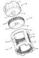
- FIG. 2is an exploded perspective view illustrating a device according to one embodiment.
- FIG. 3is a top perspective view illustrating a gear according to one embodiment.
- FIG. 4is a bottom perspective view illustrating a gear according to one embodiment.
- FIG. 5is a top perspective view illustrating an inner member according to one embodiment.
- FIG. 6is a bottom perspective view illustrating an inner member according to one embodiment.
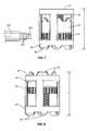
- FIG. 7is a side view illustrating a device and a tool according to one embodiment.
- FIG. 8is a side view illustrating a device according to one embodiment.
- FIG. 9is a perspective view illustrating an inner member according to one embodiment.
- FIG. 10is a perspective view illustrating a threaded member according to one embodiment.
- FIG. 11is a schematic view illustrating an inner member and an outer member according to one embodiment.
- the present applicationis directed to an expandable intervertebral device.
- One context in which the device may be usedis a corpectomy procedure to replace one or more vertebral members.
- the deviceis adjustable between a first orientation with a first overall height, and a second orientation with a second overall height.
- the devicegenerally includes an inner member, an outer member, and a gear. Rotation of the gear causes relative movement between the inner and outer members to move between the first and second orientations and adjust the overall height.
- FIG. 1illustrates one embodiment of the device and includes an outer member 20 , an inner member 30 and a gear 40 .
- the gear 40is positioned within the outer member 20 , and positioned below the inner member 30 .
- Gear 40is threaded to engage threads 21 on the inner surface of the outer member 20 . Rotation of the gear 40 causes the threads to engage, which in turn causes the gear 40 to move axially relative to the outer member 20 . This axial movement further causes the inner member 30 to axially move relative to the outer member 20 thereby adjusting the overall height.
- outer member 20contains the inner member 30 and the gear 40 .
- outer member 20includes a frame-like structure with a first ring 22 and a second ring 23 .
- Supports 24connect the rings 22 , 23 together and are spaced radially apart with openings 26 positioned therebetween.
- the outer member 20may include an overall cylindrical shape with a circular cross-sectional shape.
- the outer member 20includes a total of two rings 22 , 23 .
- additional intermediate rings(not illustrated) may be positioned within an interior.
- the number of supports 24may vary depending upon the context of use.
- One end of the outer member 20is open to allow the inner member 30 to extend as will be explained below.
- the inner surface of the outer member 20includes threads 21 for engaging the gear 40 .
- the threads 21may extend the entire height of the outer member 20 , or along a limited section.
- stopsare positioned along the threads 21 at first and second locations to control the extent of movement of the gear 40 .
- a first stopis positioned at the first ring 22
- a second stopis positioned at the second ring 23 .
- Bone-engagement features 25extend outward from the second ring 23 to engage a vertebral member.
- the bone-engagement features 25may include a variety of shapes and sizes, and may be spaced at a variety of intervals.
- the bone-engagement featuresmay be cone-shaped, pyramid-shaped, diamond-shaped, blade-like, or other shapes that may occur to one skilled in the art.
- gear 40is rotatably positioned within the outer member 20 .
- gear 40includes an upper surface 41 spaced apart from a lower surface 42 , and including an outer sidewall 43 .
- the gear 40may include a substantially circular cross-sectional shape.
- Threads 44are positioned along the sidewall 43 to engage the threads 21 on the outer member 20 .
- the threads 44may extend along an entirety of the sidewall 43 as illustrated, or may extend over a limited section.
- the thickness of the gear 40 defined between the upper and lower surface 41 , 42may vary.
- An aperture 45may extend through a center of the gear 40 to position the inner member 30 as will be explained in more detail below.
- the upper surface 41may be relatively flat, and may further include a concave section 49 .
- the concave section 49is centered about the aperture 45 .
- Concave section 49may limit the amount of surface area in contact with the inner member 30 during rotation of the gear 40 .
- Concave section 49may also assist in maintaining the position of the inner member 30 relative to the gear 40 .
- the sidewall 43further includes teeth 46 separated by gaps 47 .
- the teeth 46are evenly spaced about the circumference of the gear 40 to engage a rotational device.
- the gaps 47form an acute angle at the intersection of first and second surfaces.
- the gaps 47may include other shapes and sizes in other embodiments.
- FIGS. 5 and 6illustrate embodiments of the inner member 30 that include an upper surface 31 and lower surface 32 spaced apart and including a sidewall 34 .
- the upper surface 31may include bone-engagement features 33 that engage a vertebral member.
- the bone-engagement features 33may be spaced at a variety of locations along the upper surface 31 , including the peripheral edge and within an interior section.
- the bone-engagement features 33may include a variety of shapes and sizes similar to bone-engagement features 25 on the outer member 20 .
- the lower surface 32may include a post 37 that extends outward and is sized to fit within the aperture 45 of the gear 40 .
- Post 37is positioned at a center of the lower surface 32 , and may include a variety of shapes and lengths. The outer edge of the post 37 may be rounded to ease insertion into the aperture 45 , and assist in maintaining the post 37 positioned within the aperture 45 .
- the post 37may include an engagement mechanism, such as outwardly-extending arms, a flared end, or a swivel connection, that positively connects to the gear 40 .
- the lower surface 32is substantially flat to decrease frictional contact during rotation of the gear 40 .
- One or more ribs 35may extend along the sidewall 34 and mate with the supports 24 on the outer member 20 .
- the ribs 35fit within a track 27 within the supports 24 to maintain the alignment of the inner member 30 relative to the outer member 20 .
- the number of ribs 35 and tracks 27may vary depending upon the context.
- the ribs 35may also engage the outer member 20 to prevent rotation of the inner member 30 during rotation of the gear 40 . That is, the ribs 35 help maintain a rotational orientation of the inner member 30 relative to the outer member 20 .
- the ribs 35include a dovetail shape that corresponds with a similar shape of the track 27 in the supports 24 .
- FIGS. 7 and 8illustrate one method of adjusting a height of the device.
- the inner member 30In an initial orientation as illustrated in FIG. 7 , the inner member 30 is positioned within the interior of the outer member 20 .
- the bone-engagement features 33 of the inner member 30are recessed below the upper edge of the first ring 22 of the outer member 20 .
- the overall height H of the deviceis the height of the outer member 20 measured from the upper edge of the first ring 22 to the lower tips of the bone-engagement features 25 .
- the gear 40When the gear 40 is disposed within the outer member 20 , the gear teeth 46 are exposed through the openings 26 . A surgeon can engage the gear teeth 46 using a surgical tool 200 with a rotatable gear 201 .
- the rotatable gear 201includes gear teeth 202 that are sized and spaced to mate with teeth 46 on the gear 40 .
- the surgical tool 200may include an unillustrated drive train and drive source (e.g., manual, electric, pneumatic) that transmits a rotating force to the gear 201 .
- the gear 201is brought into contact with the gear 40 with the teeth 202 engaging with teeth 46 . Rotation of the gear 201 is transferred to the gear 40 causing it to move upward and downward relative to the outer member 20 .
- the gear 40will move up or down depending on the direction of rotation and on the direction of the threads.
- U.S. Pat. No. 6,190,414discloses a surgical tool for rotation and is herein incorporated by reference.
- the gear 40As the gear 40 moves upward and downward relative to the outer member 20 , the gear 40 also moves the inner member 30 .
- the gear 40may be positively connected to the inner member 30 , or may just be positioned against the inner member 30 . Rotation of the gear 40 causes the upper surface 41 of the gear 40 to slide across the lower surface 32 of the inner member 30 .
- the inner member 30moves axially relative to the outer member 20 , but does not rotate. Therefore, the bone-engagement features 33 securely purchase within the vertebral member as the overall height of the device increases.
- FIG. 8illustrates the device in an expanded, second orientation.
- the gear 40has been moved upward along the outer member 20 .
- This movementhas caused the inner member 30 to extend beyond the outer member 20 .
- the bone-engagement features 33 of the inner member 30extend outward beyond the first ring 22 of the outer member 20 .
- the devicehas an overall height H′ in this orientation that is greater than height H illustrated in the orientation of FIG. 7 .
- Additional rotation of the gear 40may cause the inner member 30 to extend further outward beyond the outer member 20 and further increase the height.
- the extent of outward movementmay be controlled by stops placed along one or both threads 21 , 44 on the outer member 20 and gear 40 .
- Rotation of the gear 40 in the opposite directionwill cause the overall height to decrease.
- the rotationcauses the gear 40 and thus the inner member 30 to move downward within the outer member 20 .
- the upper surface 41 of the gear 40directly contacts the lower surface 32 of the inner member 30 .
- intermediate elementsmay be positioned between the gear 40 and the inner member 30 .
- the outer member 20 , inner member 30 , and gear 40may include a variety of configurations.
- the outer member 20includes multiple openings 26 to accommodate the tool 200 .
- the outer member 20includes a single opening 26 .
- FIG. 9illustrates another embodiment of the inner member 30 .
- This embodimentfeatures supports 39 that extend between the upper surface 31 and a lower ring 38 .
- the supportsmay be spaced apart forming a substantially open interior.
- a post 37is positioned within the interior and extends downward from the upper surface 31 beyond the lower ring 38 to engage the gear 40 in a manner similar to that described above.
- the lower ring 38includes a lower surface 32 that contacts the gear 40 .
- Ribs 35may be positioned on one or more of the supports to engage the outer member 20 and prevent rotation of the inner member 30 .
- the gear 40includes teeth 46 along an outer edge.
- a threaded member 60is sized to fit within the outer member 20 .
- Threaded member 60includes an upper surface 61 , lower surface 62 , and a sidewall 63 .
- Threads 64are position on the sidewall 63 to engage threads 21 on the outer member 20 .
- An aperture 65may be positioned to receive the post 37 on the inner member 30 .
- Threaded member 60is similar to gear 40 , except there are no teeth positioned along the sidewalls 63 . Rotation of the threaded member 60 may be accomplished by manual rotation by the surgeon, or a surgical tool that engages with the member 60 at the upper or lower surfaces 61 , 62 , or the sidewall 63 .
- the devicemay be constructed from a variety of materials including biocompatible metal alloys such as titanium, cobalt-chrome, and stainless steel. Other constructions include non-metallic materials such as ceramics, resins, or polymers, such as UHMWPE and implantable grade polyetheretherketone (PEEK) or other similar materials (e.g., PAEK, PEKK, and PEK).
- the devicemay also be constructed of synthetic or natural bone or bone composites. Those skilled in the art will comprehend that there are a variety of other suitable material choices.
- the devicemay be used in a variety of different vertebral procedures.
- the devicemay be inserted using different approaches, including anterior, posterior, postero-lateral, antero-lateral and lateral. Further, the device may be used in various regions of the spine including the cervical, thoracic, lumbar and/or sacral portions of the spine.
Landscapes
- Health & Medical Sciences (AREA)
- Orthopedic Medicine & Surgery (AREA)
- Engineering & Computer Science (AREA)
- Biomedical Technology (AREA)
- Heart & Thoracic Surgery (AREA)
- Cardiology (AREA)
- Oral & Maxillofacial Surgery (AREA)
- Transplantation (AREA)
- Neurology (AREA)
- Vascular Medicine (AREA)
- Life Sciences & Earth Sciences (AREA)
- Animal Behavior & Ethology (AREA)
- General Health & Medical Sciences (AREA)
- Public Health (AREA)
- Veterinary Medicine (AREA)
- Prostheses (AREA)
Abstract
Description
Claims (16)
Priority Applications (1)
| Application Number | Priority Date | Filing Date | Title |
|---|---|---|---|
| US11/409,708US8657882B2 (en) | 2006-04-24 | 2006-04-24 | Expandable intervertebral devices and methods of use |
Applications Claiming Priority (1)
| Application Number | Priority Date | Filing Date | Title |
|---|---|---|---|
| US11/409,708US8657882B2 (en) | 2006-04-24 | 2006-04-24 | Expandable intervertebral devices and methods of use |
Publications (2)
| Publication Number | Publication Date |
|---|---|
| US20070250171A1 US20070250171A1 (en) | 2007-10-25 |
| US8657882B2true US8657882B2 (en) | 2014-02-25 |
Family
ID=38620487
Family Applications (1)
| Application Number | Title | Priority Date | Filing Date |
|---|---|---|---|
| US11/409,708Active2029-12-07US8657882B2 (en) | 2006-04-24 | 2006-04-24 | Expandable intervertebral devices and methods of use |
Country Status (1)
| Country | Link |
|---|---|
| US (1) | US8657882B2 (en) |
Cited By (8)
| Publication number | Priority date | Publication date | Assignee | Title |
|---|---|---|---|---|
| US9566167B2 (en) | 2013-08-22 | 2017-02-14 | K2M, Inc. | Expandable spinal implant |
| US9844446B2 (en) | 2016-05-05 | 2017-12-19 | Globus Medical, Inc. | Expandable vertebral implant |
| US10363142B2 (en) | 2014-12-11 | 2019-07-30 | K2M, Inc. | Expandable spinal implants |
| US10441430B2 (en) | 2017-07-24 | 2019-10-15 | K2M, Inc. | Expandable spinal implants |
| US20200085587A1 (en)* | 2015-12-21 | 2020-03-19 | Ctl Medical Corporation | Modular footprint cage system |
| US10842651B2 (en) | 2016-06-10 | 2020-11-24 | Globus Medical, Inc. | Vertebral implants and attachment assemblies |
| US11109979B2 (en) | 2018-02-16 | 2021-09-07 | Michael Craig McMains | Expandable interbody device |
| US20240407926A1 (en)* | 2023-06-07 | 2024-12-12 | Biedermann Technologies Gmbh & Co. Kg | Implant for engagement between vertebrae, and implant kit |
Families Citing this family (36)
| Publication number | Priority date | Publication date | Assignee | Title |
|---|---|---|---|---|
| US8328871B2 (en)* | 2006-11-09 | 2012-12-11 | Warsaw Orthopedic, Inc. | Expanding vertebral body implant |
| US8182537B2 (en) | 2007-10-30 | 2012-05-22 | Aesculap Implant Systems, Llc | Vertebral body replacement device and method for use to maintain a space between two vertebral bodies within a spine |
| US8142441B2 (en)* | 2008-10-16 | 2012-03-27 | Aesculap Implant Systems, Llc | Surgical instrument and method of use for inserting an implant between two bones |
| US8591587B2 (en) | 2007-10-30 | 2013-11-26 | Aesculap Implant Systems, Llc | Vertebral body replacement device and method for use to maintain a space between two vertebral bodies within a spine |
| US8323345B2 (en)* | 2008-02-14 | 2012-12-04 | U.S. Spine, Inc. | Anterior lumbar interbody fusion cage device and associated method |
| WO2009151734A1 (en)* | 2008-03-28 | 2009-12-17 | K2M, Inc. | Expandable cage |
| EP2271289A4 (en) | 2008-03-28 | 2013-01-09 | K2M Inc | Expandable cage with locking device |
| US8523944B2 (en) | 2008-12-31 | 2013-09-03 | Spinex Tec, Llc | Methods and apparatus for vertebral body distraction and fusion employing flexure members |
| US8721723B2 (en) | 2009-01-12 | 2014-05-13 | Globus Medical, Inc. | Expandable vertebral prosthesis |
| US8252054B2 (en)* | 2009-01-14 | 2012-08-28 | Stout Medical Group, L.P. | Expandable support device and method of use |
| US8142435B2 (en) | 2009-02-19 | 2012-03-27 | Aesculap Implant Systems, Llc | Multi-functional surgical instrument and method of use for inserting an implant between two bones |
| US9387090B2 (en) | 2009-03-12 | 2016-07-12 | Nuvasive, Inc. | Vertebral body replacement |
| US8628577B1 (en) | 2009-03-19 | 2014-01-14 | Ex Technology, Llc | Stable device for intervertebral distraction and fusion |
| WO2011011626A2 (en) | 2009-07-22 | 2011-01-27 | Spinex Tec, Llc | Coaxial screw gear sleeve mechanism |
| US8636746B2 (en) | 2009-12-31 | 2014-01-28 | Spinex Tec, Llc | Methods and apparatus for insertion of vertebral body distraction and fusion devices |
| US8591585B2 (en) | 2010-04-12 | 2013-11-26 | Globus Medical, Inc. | Expandable vertebral implant |
| US8870880B2 (en) | 2010-04-12 | 2014-10-28 | Globus Medical, Inc. | Angling inserter tool for expandable vertebral implant |
| US9301850B2 (en) | 2010-04-12 | 2016-04-05 | Globus Medical, Inc. | Expandable vertebral implant |
| US9579211B2 (en) | 2010-04-12 | 2017-02-28 | Globus Medical, Inc. | Expandable vertebral implant |
| US11426287B2 (en) | 2010-04-12 | 2022-08-30 | Globus Medical Inc. | Expandable vertebral implant |
| US8377140B2 (en) | 2011-01-12 | 2013-02-19 | Ebi, Llc | Expandable spinal implant device |
| US8740980B2 (en) | 2011-01-27 | 2014-06-03 | Warsaw Orthopedic, Inc. | Expandable medical implant |
| US9283086B2 (en) | 2011-03-03 | 2016-03-15 | Life Spine, Inc. | Expandable corpectomy cage |
| DE102012105123B3 (en)* | 2012-06-13 | 2013-09-12 | Hipp Medical Ag | Fixation device for fixing fractured ends of bones of a bone fracture |
| US9456908B2 (en) | 2013-03-12 | 2016-10-04 | Coorstek Medical Llc | Fusion cage |
| US9707096B2 (en) | 2013-03-14 | 2017-07-18 | K2M, Inc. | Spinal fixation device |
| US10292832B2 (en) | 2013-03-14 | 2019-05-21 | Ohio State Innovation Foundation | Spinal fixation device |
| US9968460B2 (en) | 2013-03-15 | 2018-05-15 | Medsmart Innovation Inc. | Dynamic spinal segment replacement |
| US9808354B2 (en) | 2014-01-17 | 2017-11-07 | Stryker European Holdings I, Llc | Implant insertion tool |
| US9486328B2 (en) | 2014-04-01 | 2016-11-08 | Ex Technology, Llc | Expandable intervertebral cage |
| US10327908B2 (en) | 2015-09-18 | 2019-06-25 | K2M, Inc. | Corpectomy device and methods of use thereof |
| CN107951582A (en)* | 2017-11-10 | 2018-04-24 | 广州市健齿生物科技有限公司 | The personalized tooth implant that a kind of claw is fixed |
| US11234835B2 (en) | 2019-03-05 | 2022-02-01 | Octagon Spine Llc | Transversely expandable minimally invasive intervertebral cage |
| US11497622B2 (en) | 2019-03-05 | 2022-11-15 | Ex Technology, Llc | Transversely expandable minimally invasive intervertebral cage and insertion and extraction device |
| WO2023055783A1 (en) | 2021-09-29 | 2023-04-06 | Ex Technology, Llc | Expandable intervertebral cage |
| US12011365B2 (en) | 2022-07-18 | 2024-06-18 | Octagon Spine Llc | Transversely expandable minimally invasive inter vertebral cage |
Citations (78)
| Publication number | Priority date | Publication date | Assignee | Title |
|---|---|---|---|---|
| US2424489A (en)* | 1945-06-30 | 1947-07-22 | American Enka Corp | Thread advancing reel |
| US2536836A (en)* | 1947-05-05 | 1951-01-02 | Leonard C Bowling | Valve |
| US4553273A (en) | 1983-11-23 | 1985-11-19 | Henry Ford Hospital | Vertebral body prosthesis and spine stabilizing method |
| US4554914A (en) | 1983-10-04 | 1985-11-26 | Kapp John P | Prosthetic vertebral body |
| US4636217A (en)* | 1985-04-23 | 1987-01-13 | Regents Of The University Of Minnesota | Anterior spinal implant |
| US4657550A (en) | 1984-12-21 | 1987-04-14 | Daher Youssef H | Buttressing device usable in a vertebral prosthesis |
| US4820305A (en) | 1986-11-03 | 1989-04-11 | Harms Juergen | Place holder, in particular for a vertebra body |
| US4932975A (en) | 1989-10-16 | 1990-06-12 | Vanderbilt University | Vertebral prosthesis |
| US5026373A (en) | 1988-10-17 | 1991-06-25 | Surgical Dynamics, Inc. | Surgical method and apparatus for fusing adjacent bone structures |
| US5062850A (en) | 1990-01-16 | 1991-11-05 | University Of Florida | Axially-fixed vertebral body prosthesis and method of fixation |
| US5236460A (en) | 1990-02-12 | 1993-08-17 | Midas Rex Pneumatic Tools, Inc. | Vertebral body prosthesis |
| US5336223A (en) | 1993-02-04 | 1994-08-09 | Rogers Charles L | Telescoping spinal fixator |
| US5360430A (en) | 1993-07-29 | 1994-11-01 | Lin Chih I | Intervertebral locking device |
| US5397364A (en) | 1993-10-12 | 1995-03-14 | Danek Medical, Inc. | Anterior interbody fusion device |
| US5480442A (en) | 1993-06-24 | 1996-01-02 | Man Ceramics Gmbh | Fixedly adjustable intervertebral prosthesis |
| US5522899A (en) | 1988-06-28 | 1996-06-04 | Sofamor Danek Properties, Inc. | Artificial spinal fusion implants |
| US5571192A (en) | 1994-07-02 | 1996-11-05 | Heinrich Ulrich | Prosthetic vertebral implant |
| US5571190A (en) | 1993-08-20 | 1996-11-05 | Heinrich Ulrich | Implant for the replacement of vertebrae and/or stabilization and fixing of the spinal column |
| US5658335A (en) | 1995-03-09 | 1997-08-19 | Cohort Medical Products Group, Inc. | Spinal fixator |
| US5702455A (en) | 1996-07-03 | 1997-12-30 | Saggar; Rahul | Expandable prosthesis for spinal fusion |
| US5702451A (en) | 1995-02-14 | 1997-12-30 | Biedermann; Lutz | Space holder, in particular for a vertebra or an intervertebral disk |
| US5702453A (en) | 1994-12-09 | 1997-12-30 | Sofamor Danek Group | Adjustable vertebral body replacement |
| US5723013A (en) | 1995-02-06 | 1998-03-03 | Jbs S.A. | Spacer implant for substituting missing vertebrae |
| US5725528A (en) | 1997-02-12 | 1998-03-10 | Third Millennium Engineering, Llc | Modular polyaxial locking pedicle screw |
| US5776198A (en) | 1994-12-09 | 1998-07-07 | Sdgi Holdings, Inc. | Adjustable vertebral body replacement |
| US5800550A (en)* | 1996-03-13 | 1998-09-01 | Sertich; Mario M. | Interbody fusion cage |
| US5989290A (en) | 1995-05-24 | 1999-11-23 | Biedermann; Lutz | Height-adjustable artificial vertebral body |
| US6015436A (en) | 1996-06-07 | 2000-01-18 | Heinrich Ulrich | Implant for filling a space between vertebrae |
| US6086613A (en) | 1997-12-23 | 2000-07-11 | Depuy Acromed, Inc. | Spacer assembly for use in spinal surgeries |
| US6156038A (en) | 1997-01-02 | 2000-12-05 | St. Francis Medical Technologies, Inc. | Spine distraction implant and method |
| US6176881B1 (en) | 1997-04-15 | 2001-01-23 | Synthes | Telescopic vertebral prosthesis |
| US6190413B1 (en) | 1998-04-16 | 2001-02-20 | Ulrich Gmbh & Co. Kg | Vertebral implant |
| US6190414B1 (en) | 1996-10-31 | 2001-02-20 | Surgical Dynamics Inc. | Apparatus for fusion of adjacent bone structures |
| US6193755B1 (en) | 1996-09-26 | 2001-02-27 | Howmedica Gmbh | Spinal cage assembly |
| US6193756B1 (en) | 1997-09-30 | 2001-02-27 | Sulzer Orthopaedie Ag | Tubular support body for bridging two vertebrae |
| EP1080703A2 (en) | 1999-09-02 | 2001-03-07 | Howmedica Osteonics Corp. | Spinal implant |
| US6200348B1 (en) | 1998-02-06 | 2001-03-13 | Biedermann, Motech Gmbh | Spacer with adjustable axial length |
| US6296665B1 (en) | 2000-03-20 | 2001-10-02 | Electro-Biology, Inc. | Method and apparatus for spinal fixation |
| US6299644B1 (en) | 1997-06-16 | 2001-10-09 | Paul Vanderschot | Vertebral replacement implant |
| US6344057B1 (en) | 1994-11-22 | 2002-02-05 | Sdgi Holdings, Inc. | Adjustable vertebral body replacement |
| US6352556B1 (en) | 1999-01-22 | 2002-03-05 | Signus Medizintechnik Gmbh | Vertebral column replacement body |
| EP1188424A1 (en) | 2000-08-21 | 2002-03-20 | Christos Kalaitzis | Prosthesis for replacement of a whole vertebral unit |
| US6375683B1 (en) | 1997-05-02 | 2002-04-23 | Stryker France S.A. | Implant in particular for replacing a vertebral body in surgery of the spine |
| US6375681B1 (en) | 1998-06-23 | 2002-04-23 | Ebi, L.P. | Vertebral body replacement |
| US6395034B1 (en) | 1999-11-24 | 2002-05-28 | Loubert Suddaby | Intervertebral disc prosthesis |
| US6409766B1 (en) | 1998-07-30 | 2002-06-25 | Expanding Concepts, Llc | Collapsible and expandable interbody fusion device |
| US6436140B1 (en)* | 1998-08-28 | 2002-08-20 | Sofamor S.N.C. | Expandable interbody fusion cage and method for insertion |
| US6454806B1 (en) | 1999-07-26 | 2002-09-24 | Advanced Prosthetic Technologies, Inc. | Spinal surgical prosthesis |
| US6520991B2 (en) | 1999-05-11 | 2003-02-18 | Donald R. Huene | Expandable implant for inter-vertebral stabilization, and a method of stabilizing vertebrae |
| US6524341B2 (en) | 1998-10-15 | 2003-02-25 | Synthes (Usa) | Telescopic vertebral prosthesis |
| US20030045877A1 (en)* | 2001-08-29 | 2003-03-06 | Chung-Chun Yeh | Device for fixing spinal column under treatment |
| US6562074B2 (en) | 2001-10-17 | 2003-05-13 | Medicinelodge, Inc. | Adjustable bone fusion implant and method |
| US6610090B1 (en) | 1998-01-30 | 2003-08-26 | Königsee Implantate und Instrumente zur Ostheosynthese GmbH | Height-adjustable vertebral implant |
| US6616695B1 (en) | 1998-01-30 | 2003-09-09 | Stryker Spine | Implant for replacing a vertebra |
| WO2003073964A1 (en) | 2002-03-02 | 2003-09-12 | Schaefer Bernd | Distractible vertebral column implant and distracting tool |
| US20030191531A1 (en) | 2002-03-21 | 2003-10-09 | Berry Bret M. | Vertebral body and disc space replacement devices |
| US20030199980A1 (en) | 2002-04-23 | 2003-10-23 | Uwe Siedler | Vertebral column implant |
| US6645249B2 (en) | 2001-10-18 | 2003-11-11 | Spinecore, Inc. | Intervertebral spacer device having a multi-pronged domed spring |
| WO2003096937A1 (en) | 2002-05-21 | 2003-11-27 | Peter Metz-Stavenhagen | Vertebral body placeholder |
| US6660038B2 (en) | 2000-03-22 | 2003-12-09 | Synthes (Usa) | Skeletal reconstruction cages |
| US20040049271A1 (en) | 2001-08-03 | 2004-03-11 | Lutz Biedermann | Spacer having a variable axial length |
| WO2004026157A2 (en) | 2002-09-23 | 2004-04-01 | Sdgi Holdings, Inc. | Expansion apparatus for adjustable spinal implant |
| US6719796B2 (en) | 1999-07-26 | 2004-04-13 | Advanced Prosthetic Technologies, Inc. | Spinal surgical prosthesis |
| US20040073314A1 (en) | 2002-03-21 | 2004-04-15 | White John L. | Vertebral body and disc space replacement devices |
| US6723126B1 (en) | 2002-11-01 | 2004-04-20 | Sdgi Holdings, Inc. | Laterally expandable cage |
| US6752832B2 (en) | 2000-12-27 | 2004-06-22 | Ulrich Gmbh & Co., Kg | Vertebral implant and setting tool therefor |
| US6758862B2 (en) | 2002-03-21 | 2004-07-06 | Sdgi Holdings, Inc. | Vertebral body and disc space replacement devices |
| US6783547B2 (en) | 2002-04-05 | 2004-08-31 | Howmedica Corp. | Apparatus for fusing adjacent bone structures |
| US6793678B2 (en) | 2002-06-27 | 2004-09-21 | Depuy Acromed, Inc. | Prosthetic intervertebral motion disc having dampening |
| US20040186569A1 (en) | 2003-03-20 | 2004-09-23 | Berry Bret M. | Height adjustable vertebral body and disc space replacement devices |
| US6808538B2 (en) | 2002-03-15 | 2004-10-26 | Stryker Spine | Vertebral body spacer having variable wedged endplates |
| WO2004096103A1 (en) | 2003-04-28 | 2004-11-11 | Synthes Ag Chur | Intervertebral implant |
| US20050004572A1 (en) | 2002-09-12 | 2005-01-06 | Lutz Biedermann | Space keeper for vertebrae or intervertebral disks |
| US20050060036A1 (en) | 2003-05-21 | 2005-03-17 | Robert Schultz | Spinal column implant |
| US20050090898A1 (en) | 2003-10-22 | 2005-04-28 | Sdgi Holdings, Inc. | Vertebral body replacement implant |
| WO2005055887A2 (en) | 2003-12-11 | 2005-06-23 | Deltacor Gmbh | Length-adjustable implant for the vertebral column |
| US20060241621A1 (en)* | 2005-04-12 | 2006-10-26 | Moskowitz Mosheh T | Bi-directional fixating transvertebral body screws, zero-profile horizontal intervertebral miniplates, expansile intervertebral body fusion devices, and posterior motion-calibrating interarticulating joint stapling device for spinal fusion |
| US20070270960A1 (en)* | 2006-04-24 | 2007-11-22 | Sdgi Holdings, Inc. | Extendable anchor in a vertebral implant and methods of use |
Family Cites Families (2)
| Publication number | Priority date | Publication date | Assignee | Title |
|---|---|---|---|---|
| JP3016415B2 (en)* | 1995-06-14 | 2000-03-06 | ブラザー工業株式会社 | Data transfer method and data transfer system |
| US6652074B2 (en)* | 1998-03-25 | 2003-11-25 | Silverbrook Research Pty Ltd | Ink jet nozzle assembly including displaceable ink pusher |
- 2006
- 2006-04-24USUS11/409,708patent/US8657882B2/enactiveActive
Patent Citations (91)
| Publication number | Priority date | Publication date | Assignee | Title |
|---|---|---|---|---|
| US2424489A (en)* | 1945-06-30 | 1947-07-22 | American Enka Corp | Thread advancing reel |
| US2536836A (en)* | 1947-05-05 | 1951-01-02 | Leonard C Bowling | Valve |
| US4554914A (en) | 1983-10-04 | 1985-11-26 | Kapp John P | Prosthetic vertebral body |
| US4553273A (en) | 1983-11-23 | 1985-11-19 | Henry Ford Hospital | Vertebral body prosthesis and spine stabilizing method |
| US4657550A (en) | 1984-12-21 | 1987-04-14 | Daher Youssef H | Buttressing device usable in a vertebral prosthesis |
| US4636217A (en)* | 1985-04-23 | 1987-01-13 | Regents Of The University Of Minnesota | Anterior spinal implant |
| US4820305A (en) | 1986-11-03 | 1989-04-11 | Harms Juergen | Place holder, in particular for a vertebra body |
| US5522899A (en) | 1988-06-28 | 1996-06-04 | Sofamor Danek Properties, Inc. | Artificial spinal fusion implants |
| US6447547B1 (en) | 1988-06-28 | 2002-09-10 | Sofamor Danek Group, Inc. | Artificial spinal fusion implants |
| US5026373A (en) | 1988-10-17 | 1991-06-25 | Surgical Dynamics, Inc. | Surgical method and apparatus for fusing adjacent bone structures |
| US4932975A (en) | 1989-10-16 | 1990-06-12 | Vanderbilt University | Vertebral prosthesis |
| US5062850A (en) | 1990-01-16 | 1991-11-05 | University Of Florida | Axially-fixed vertebral body prosthesis and method of fixation |
| US5236460A (en) | 1990-02-12 | 1993-08-17 | Midas Rex Pneumatic Tools, Inc. | Vertebral body prosthesis |
| US5336223A (en) | 1993-02-04 | 1994-08-09 | Rogers Charles L | Telescoping spinal fixator |
| US5480442A (en) | 1993-06-24 | 1996-01-02 | Man Ceramics Gmbh | Fixedly adjustable intervertebral prosthesis |
| US5360430A (en) | 1993-07-29 | 1994-11-01 | Lin Chih I | Intervertebral locking device |
| US5571190A (en) | 1993-08-20 | 1996-11-05 | Heinrich Ulrich | Implant for the replacement of vertebrae and/or stabilization and fixing of the spinal column |
| US5397364A (en) | 1993-10-12 | 1995-03-14 | Danek Medical, Inc. | Anterior interbody fusion device |
| US5571192A (en) | 1994-07-02 | 1996-11-05 | Heinrich Ulrich | Prosthetic vertebral implant |
| US6344057B1 (en) | 1994-11-22 | 2002-02-05 | Sdgi Holdings, Inc. | Adjustable vertebral body replacement |
| US5776197A (en) | 1994-12-09 | 1998-07-07 | Sdgi Holdings, Inc. | Adjustable vertebral body replacement |
| US5702453A (en) | 1994-12-09 | 1997-12-30 | Sofamor Danek Group | Adjustable vertebral body replacement |
| US5776198A (en) | 1994-12-09 | 1998-07-07 | Sdgi Holdings, Inc. | Adjustable vertebral body replacement |
| US5723013A (en) | 1995-02-06 | 1998-03-03 | Jbs S.A. | Spacer implant for substituting missing vertebrae |
| US5702451A (en) | 1995-02-14 | 1997-12-30 | Biedermann; Lutz | Space holder, in particular for a vertebra or an intervertebral disk |
| US5658335A (en) | 1995-03-09 | 1997-08-19 | Cohort Medical Products Group, Inc. | Spinal fixator |
| US5989290A (en) | 1995-05-24 | 1999-11-23 | Biedermann; Lutz | Height-adjustable artificial vertebral body |
| US5800550A (en)* | 1996-03-13 | 1998-09-01 | Sertich; Mario M. | Interbody fusion cage |
| US6015436A (en) | 1996-06-07 | 2000-01-18 | Heinrich Ulrich | Implant for filling a space between vertebrae |
| US5702455A (en) | 1996-07-03 | 1997-12-30 | Saggar; Rahul | Expandable prosthesis for spinal fusion |
| US6193755B1 (en) | 1996-09-26 | 2001-02-27 | Howmedica Gmbh | Spinal cage assembly |
| US6190414B1 (en) | 1996-10-31 | 2001-02-20 | Surgical Dynamics Inc. | Apparatus for fusion of adjacent bone structures |
| US6156038A (en) | 1997-01-02 | 2000-12-05 | St. Francis Medical Technologies, Inc. | Spine distraction implant and method |
| US5725528A (en) | 1997-02-12 | 1998-03-10 | Third Millennium Engineering, Llc | Modular polyaxial locking pedicle screw |
| US6176881B1 (en) | 1997-04-15 | 2001-01-23 | Synthes | Telescopic vertebral prosthesis |
| US6375683B1 (en) | 1997-05-02 | 2002-04-23 | Stryker France S.A. | Implant in particular for replacing a vertebral body in surgery of the spine |
| US6299644B1 (en) | 1997-06-16 | 2001-10-09 | Paul Vanderschot | Vertebral replacement implant |
| US6193756B1 (en) | 1997-09-30 | 2001-02-27 | Sulzer Orthopaedie Ag | Tubular support body for bridging two vertebrae |
| US6776798B2 (en) | 1997-12-23 | 2004-08-17 | Depuy Acromed, Inc. | Spacer assembly for use in spinal surgeries having end cap which includes serrated surface |
| US6086613A (en) | 1997-12-23 | 2000-07-11 | Depuy Acromed, Inc. | Spacer assembly for use in spinal surgeries |
| US6908485B2 (en) | 1998-01-30 | 2005-06-21 | Stryker Spine | Implant for replacing a vertebra |
| US6616695B1 (en) | 1998-01-30 | 2003-09-09 | Stryker Spine | Implant for replacing a vertebra |
| US6610090B1 (en) | 1998-01-30 | 2003-08-26 | Königsee Implantate und Instrumente zur Ostheosynthese GmbH | Height-adjustable vertebral implant |
| US6200348B1 (en) | 1998-02-06 | 2001-03-13 | Biedermann, Motech Gmbh | Spacer with adjustable axial length |
| US6190413B1 (en) | 1998-04-16 | 2001-02-20 | Ulrich Gmbh & Co. Kg | Vertebral implant |
| US6375681B1 (en) | 1998-06-23 | 2002-04-23 | Ebi, L.P. | Vertebral body replacement |
| US6409766B1 (en) | 1998-07-30 | 2002-06-25 | Expanding Concepts, Llc | Collapsible and expandable interbody fusion device |
| US6436140B1 (en)* | 1998-08-28 | 2002-08-20 | Sofamor S.N.C. | Expandable interbody fusion cage and method for insertion |
| US6524341B2 (en) | 1998-10-15 | 2003-02-25 | Synthes (Usa) | Telescopic vertebral prosthesis |
| US6352556B1 (en) | 1999-01-22 | 2002-03-05 | Signus Medizintechnik Gmbh | Vertebral column replacement body |
| US6520991B2 (en) | 1999-05-11 | 2003-02-18 | Donald R. Huene | Expandable implant for inter-vertebral stabilization, and a method of stabilizing vertebrae |
| US6719796B2 (en) | 1999-07-26 | 2004-04-13 | Advanced Prosthetic Technologies, Inc. | Spinal surgical prosthesis |
| US6454806B1 (en) | 1999-07-26 | 2002-09-24 | Advanced Prosthetic Technologies, Inc. | Spinal surgical prosthesis |
| US6866682B1 (en) | 1999-09-02 | 2005-03-15 | Stryker Spine | Distractable corpectomy device |
| EP1080703A2 (en) | 1999-09-02 | 2001-03-07 | Howmedica Osteonics Corp. | Spinal implant |
| US20050113921A1 (en) | 1999-09-02 | 2005-05-26 | Stryker Spine | Distractable corpectomy device |
| US6395034B1 (en) | 1999-11-24 | 2002-05-28 | Loubert Suddaby | Intervertebral disc prosthesis |
| US6296665B1 (en) | 2000-03-20 | 2001-10-02 | Electro-Biology, Inc. | Method and apparatus for spinal fixation |
| US20040181283A1 (en) | 2000-03-22 | 2004-09-16 | Boyer Michael L. | Skeletal reconstruction cages |
| US6660038B2 (en) | 2000-03-22 | 2003-12-09 | Synthes (Usa) | Skeletal reconstruction cages |
| EP1188424A1 (en) | 2000-08-21 | 2002-03-20 | Christos Kalaitzis | Prosthesis for replacement of a whole vertebral unit |
| US6752832B2 (en) | 2000-12-27 | 2004-06-22 | Ulrich Gmbh & Co., Kg | Vertebral implant and setting tool therefor |
| US20040049271A1 (en) | 2001-08-03 | 2004-03-11 | Lutz Biedermann | Spacer having a variable axial length |
| US20030045877A1 (en)* | 2001-08-29 | 2003-03-06 | Chung-Chun Yeh | Device for fixing spinal column under treatment |
| US6852129B2 (en) | 2001-10-17 | 2005-02-08 | Movdice Holding, Inc. | Adjustable bone fusion implant and method |
| US6562074B2 (en) | 2001-10-17 | 2003-05-13 | Medicinelodge, Inc. | Adjustable bone fusion implant and method |
| US6863673B2 (en) | 2001-10-17 | 2005-03-08 | Movdice Holding, Inc. | Methods for adjustable bone fusion implants |
| US6648917B2 (en) | 2001-10-17 | 2003-11-18 | Medicinelodge, Inc. | Adjustable bone fusion implant and method |
| US6645249B2 (en) | 2001-10-18 | 2003-11-11 | Spinecore, Inc. | Intervertebral spacer device having a multi-pronged domed spring |
| US20040172129A1 (en) | 2002-03-02 | 2004-09-02 | Bernd Schafer | Distractable vertebral column and distracting tool |
| WO2003073964A1 (en) | 2002-03-02 | 2003-09-12 | Schaefer Bernd | Distractible vertebral column implant and distracting tool |
| US6808538B2 (en) | 2002-03-15 | 2004-10-26 | Stryker Spine | Vertebral body spacer having variable wedged endplates |
| US6758862B2 (en) | 2002-03-21 | 2004-07-06 | Sdgi Holdings, Inc. | Vertebral body and disc space replacement devices |
| US20030191531A1 (en) | 2002-03-21 | 2003-10-09 | Berry Bret M. | Vertebral body and disc space replacement devices |
| US20040073314A1 (en) | 2002-03-21 | 2004-04-15 | White John L. | Vertebral body and disc space replacement devices |
| US6783547B2 (en) | 2002-04-05 | 2004-08-31 | Howmedica Corp. | Apparatus for fusing adjacent bone structures |
| US20030199980A1 (en) | 2002-04-23 | 2003-10-23 | Uwe Siedler | Vertebral column implant |
| WO2003096937A1 (en) | 2002-05-21 | 2003-11-27 | Peter Metz-Stavenhagen | Vertebral body placeholder |
| US6793678B2 (en) | 2002-06-27 | 2004-09-21 | Depuy Acromed, Inc. | Prosthetic intervertebral motion disc having dampening |
| US20050004572A1 (en) | 2002-09-12 | 2005-01-06 | Lutz Biedermann | Space keeper for vertebrae or intervertebral disks |
| WO2004026157A2 (en) | 2002-09-23 | 2004-04-01 | Sdgi Holdings, Inc. | Expansion apparatus for adjustable spinal implant |
| US6723126B1 (en) | 2002-11-01 | 2004-04-20 | Sdgi Holdings, Inc. | Laterally expandable cage |
| US20040186569A1 (en) | 2003-03-20 | 2004-09-23 | Berry Bret M. | Height adjustable vertebral body and disc space replacement devices |
| WO2004096103A1 (en) | 2003-04-28 | 2004-11-11 | Synthes Ag Chur | Intervertebral implant |
| US20050060036A1 (en) | 2003-05-21 | 2005-03-17 | Robert Schultz | Spinal column implant |
| US20050090898A1 (en) | 2003-10-22 | 2005-04-28 | Sdgi Holdings, Inc. | Vertebral body replacement implant |
| WO2005055887A2 (en) | 2003-12-11 | 2005-06-23 | Deltacor Gmbh | Length-adjustable implant for the vertebral column |
| DE10357926B3 (en)* | 2003-12-11 | 2005-09-01 | Deltacor Gmbh | Length adjustable spinal implant |
| US20060241762A1 (en)* | 2003-12-11 | 2006-10-26 | Deltacor Gmbh | Height-adjustable spinal implant and operating instrument for the implant |
| US20060241621A1 (en)* | 2005-04-12 | 2006-10-26 | Moskowitz Mosheh T | Bi-directional fixating transvertebral body screws, zero-profile horizontal intervertebral miniplates, expansile intervertebral body fusion devices, and posterior motion-calibrating interarticulating joint stapling device for spinal fusion |
| US20070270960A1 (en)* | 2006-04-24 | 2007-11-22 | Sdgi Holdings, Inc. | Extendable anchor in a vertebral implant and methods of use |
Cited By (19)
| Publication number | Priority date | Publication date | Assignee | Title |
|---|---|---|---|---|
| US9566167B2 (en) | 2013-08-22 | 2017-02-14 | K2M, Inc. | Expandable spinal implant |
| US12257159B2 (en) | 2014-12-11 | 2025-03-25 | K2M, Inc. | Expandable spinal implants |
| US11331200B2 (en) | 2014-12-11 | 2022-05-17 | K2M, Inc. | Expandable spinal implants |
| US10363142B2 (en) | 2014-12-11 | 2019-07-30 | K2M, Inc. | Expandable spinal implants |
| US11633289B2 (en)* | 2015-12-21 | 2023-04-25 | Ctl Medical Corporation | Modular footprint cage system |
| US20200085587A1 (en)* | 2015-12-21 | 2020-03-19 | Ctl Medical Corporation | Modular footprint cage system |
| US10646352B2 (en) | 2016-05-05 | 2020-05-12 | Globus Medical, Inc. | Expandable vertebral implant |
| US10159581B2 (en) | 2016-05-05 | 2018-12-25 | Globus Medical, Inc. | Expandable vertebral implant |
| US9844446B2 (en) | 2016-05-05 | 2017-12-19 | Globus Medical, Inc. | Expandable vertebral implant |
| US11684481B2 (en) | 2016-05-05 | 2023-06-27 | Globus Medical, Inc. | Expandable vertebral implant |
| US10842651B2 (en) | 2016-06-10 | 2020-11-24 | Globus Medical, Inc. | Vertebral implants and attachment assemblies |
| US11690735B2 (en) | 2016-06-10 | 2023-07-04 | Globus Medical, Inc. | Vertebral implants and attachment assemblies |
| US12232983B2 (en) | 2016-06-10 | 2025-02-25 | Globus Medical, Inc. | Vertebral implants and attachment assemblies |
| US10441430B2 (en) | 2017-07-24 | 2019-10-15 | K2M, Inc. | Expandable spinal implants |
| US12029662B2 (en) | 2017-07-24 | 2024-07-09 | K2M, Inc. | Expandable spinal implants |
| US11291552B2 (en) | 2017-07-24 | 2022-04-05 | K2M, Inc. | Expandable spinal implants |
| US11109979B2 (en) | 2018-02-16 | 2021-09-07 | Michael Craig McMains | Expandable interbody device |
| US20240407926A1 (en)* | 2023-06-07 | 2024-12-12 | Biedermann Technologies Gmbh & Co. Kg | Implant for engagement between vertebrae, and implant kit |
| US12396864B2 (en)* | 2023-06-07 | 2025-08-26 | Biedermann Technologies Gmbh & Co. Kg | Implant for engagement between vertebrae, and implant kit |
Also Published As
| Publication number | Publication date |
|---|---|
| US20070250171A1 (en) | 2007-10-25 |
Similar Documents
| Publication | Publication Date | Title |
|---|---|---|
| US8657882B2 (en) | Expandable intervertebral devices and methods of use | |
| US12350171B2 (en) | Variable lordosis spacer and related methods of use | |
| US12390341B2 (en) | Variable lordosis spacer and related methods of use | |
| US11564803B2 (en) | Expandable vertebral implant | |
| US10369000B2 (en) | Expandable vertebral implant | |
| US8465547B2 (en) | Modular interbody devices and methods of use | |
| US9402739B2 (en) | Variable lordosis spacer and related methods of use | |
| US20070255414A1 (en) | Intervertebral implants with one or more covers and methods of use | |
| US9452060B2 (en) | Six degree spine stabilization devices and methods | |
| US20120197402A1 (en) | Intervertebral implant with rotating member | |
| US20070270960A1 (en) | Extendable anchor in a vertebral implant and methods of use | |
| US20090326658A1 (en) | Intervertebral prosthetic disc and method of installing same | |
| WO2016019230A1 (en) | Variable lordosis spacer and related methods of use |
Legal Events
| Date | Code | Title | Description |
|---|---|---|---|
| AS | Assignment | Owner name:SDGI HOLDINGS, INC., DELAWARE Free format text:ASSIGNMENT OF ASSIGNORS INTEREST;ASSIGNOR:BONIN, HENRY KEITH, JR.;REEL/FRAME:017805/0129 Effective date:20060420 | |
| AS | Assignment | Owner name:WARSAW ORTHOPEDIC, INC., INDIANA Free format text:MERGER;ASSIGNOR:SDGI HOLDING, INC.;REEL/FRAME:022471/0137 Effective date:20060428 Owner name:WARSAW ORTHOPEDIC, INC.,INDIANA Free format text:MERGER;ASSIGNOR:SDGI HOLDING, INC.;REEL/FRAME:022471/0137 Effective date:20060428 | |
| STCF | Information on status: patent grant | Free format text:PATENTED CASE | |
| MAFP | Maintenance fee payment | Free format text:PAYMENT OF MAINTENANCE FEE, 4TH YEAR, LARGE ENTITY (ORIGINAL EVENT CODE: M1551) Year of fee payment:4 | |
| MAFP | Maintenance fee payment | Free format text:PAYMENT OF MAINTENANCE FEE, 8TH YEAR, LARGE ENTITY (ORIGINAL EVENT CODE: M1552); ENTITY STATUS OF PATENT OWNER: LARGE ENTITY Year of fee payment:8 |