US8657858B2 - Bottom-loading pedicle screw assembly - Google Patents
Bottom-loading pedicle screw assemblyDownload PDFInfo
- Publication number
- US8657858B2 US8657858B2US12/077,940US7794008AUS8657858B2US 8657858 B2US8657858 B2US 8657858B2US 7794008 AUS7794008 AUS 7794008AUS 8657858 B2US8657858 B2US 8657858B2
- Authority
- US
- United States
- Prior art keywords
- head
- clip
- coupling element
- groove
- fastener
- Prior art date
- Legal status (The legal status is an assumption and is not a legal conclusion. Google has not performed a legal analysis and makes no representation as to the accuracy of the status listed.)
- Active, expires
Links
Images


Classifications
- A—HUMAN NECESSITIES
- A61—MEDICAL OR VETERINARY SCIENCE; HYGIENE
- A61B—DIAGNOSIS; SURGERY; IDENTIFICATION
- A61B17/00—Surgical instruments, devices or methods
- A61B17/56—Surgical instruments or methods for treatment of bones or joints; Devices specially adapted therefor
- A61B17/58—Surgical instruments or methods for treatment of bones or joints; Devices specially adapted therefor for osteosynthesis, e.g. bone plates, screws or setting implements
- A61B17/68—Internal fixation devices, including fasteners and spinal fixators, even if a part thereof projects from the skin
- A61B17/70—Spinal positioners or stabilisers, e.g. stabilisers comprising fluid filler in an implant
- A61B17/7001—Screws or hooks combined with longitudinal elements which do not contact vertebrae
- A61B17/7035—Screws or hooks, wherein a rod-clamping part and a bone-anchoring part can pivot relative to each other
- A61B17/7037—Screws or hooks, wherein a rod-clamping part and a bone-anchoring part can pivot relative to each other wherein pivoting is blocked when the rod is clamped
- A—HUMAN NECESSITIES
- A61—MEDICAL OR VETERINARY SCIENCE; HYGIENE
- A61B—DIAGNOSIS; SURGERY; IDENTIFICATION
- A61B17/00—Surgical instruments, devices or methods
- A61B17/56—Surgical instruments or methods for treatment of bones or joints; Devices specially adapted therefor
- A61B17/58—Surgical instruments or methods for treatment of bones or joints; Devices specially adapted therefor for osteosynthesis, e.g. bone plates, screws or setting implements
- A61B17/68—Internal fixation devices, including fasteners and spinal fixators, even if a part thereof projects from the skin
- A61B17/84—Fasteners therefor or fasteners being internal fixation devices
- A61B17/86—Pins or screws or threaded wires; nuts therefor
- A61B17/8605—Heads, i.e. proximal ends projecting from bone
- A—HUMAN NECESSITIES
- A61—MEDICAL OR VETERINARY SCIENCE; HYGIENE
- A61B—DIAGNOSIS; SURGERY; IDENTIFICATION
- A61B17/00—Surgical instruments, devices or methods
- A61B17/56—Surgical instruments or methods for treatment of bones or joints; Devices specially adapted therefor
- A61B17/58—Surgical instruments or methods for treatment of bones or joints; Devices specially adapted therefor for osteosynthesis, e.g. bone plates, screws or setting implements
- A61B17/68—Internal fixation devices, including fasteners and spinal fixators, even if a part thereof projects from the skin
- A61B17/70—Spinal positioners or stabilisers, e.g. stabilisers comprising fluid filler in an implant
- A61B17/7001—Screws or hooks combined with longitudinal elements which do not contact vertebrae
- A61B17/7032—Screws or hooks with U-shaped head or back through which longitudinal rods pass
Definitions
- This disclosureis directed to skeletal bone fixation systems, and more particularly to a fixation assembly for vertebrae of a spinal column.
- a typical spinal fixation assemblyincludes a fixation device, such as a screw or hook, that can be attached to a portion of a first vertebral body.
- the screwcan be coupled to a stabilization member, such as an elongate rod, that can be linked to one or more additional vertebral bodies using additional screws.
- two or more bone screws and/or hooksare secured to a vertebral body that is to be stabilized. After the screws are secured to the vertebral bodies, the screws are coupled to a spinal stabilization rod that restricts movement of the stabilized vertebra. It is important that the screws have a secure coupling with the spinal stabilization rod in order to prevent movement of the rod relative to the screw after placement.
- a tulip-like coupling element with opposing upright arms or wallsis used to secure the pedicle screw to the rod.
- the coupling element and pedicle screware configured to be coupled to an elongate stabilizer, such as a rod, that is positioned above the head of the pedicle screw.
- a compression membersuch as a compression nut, is configured to mate with the coupling element and provides a compressive force to the rod. The rod is then forced against the head of the pedicle screw, and that force is translated to the coupling element. Accordingly, the forces generated by the compression nut clamp the rod and pedicle screw head together within the coupling element.
- pedicle screw systemis a bottom-loaded system wherein the screw is loaded into the coupling element through the bottom of the coupling element. Bottom loading can allow for greater flexibility and adjustment of the coupling element relative to the screw. There is a need for improved bottom-loaded pedicle screw systems.
- the spine screw assemblysuch as a pedicle screw system.
- the spine screw assemblycomprises: a fastener having an upper end and a lower end, a head at the upper end, and an anchoring element extending between the upper and lower ends, wherein a groove is positioned in the head of the fastener; a clip sized to be positioned in the groove, wherein the annular clip transitions between a first state of increased size and a second state of decreased size, and wherein the annular clip can be locked within the groove when in the second state of decreased size and can be removed from the groove by transitioning the first state of increased size; a coupling element having an upper opening at an upper end and a lower opening at a lower end, the coupling element including a rod receiving channel adapted to receive a stabilizing rod, a bore extending through the lower end of said coupling element for receiving said fastener, and a seat adapted to engage the head when the fastener is positioned in the bore; and a compression nut engageable with
- FIG. 1 ais an illustration of a human vertebral column.
- FIG. 1 bis a superior view of a typical human vertebra.
- FIG. 1 cis a lateral view of the vertebra depicted in FIG. 1 b.
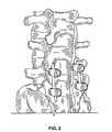
- FIG. 2is an illustration of a set of pedicle screws implanted into a human vertebral column.
- FIG. 3shows an exploded view of a bone fixation assembly according to one embodiment.
- FIG. 4Ais a lateral view of a bone fixation element according to one embodiment.
- FIG. 4Bis a lateral close-up view of a bone fixation element taken at circle 4 B of FIG. 4A .
- FIG. 5Ais a perspective view of a clip according to one embodiment.
- FIG. 5Bis a cross-sectional view of the clip taken along lines B-B of FIG. 5A .
- FIG. 6is a lateral view of the clip of FIG. 5A installed in the bone fixation element of FIG. 4A .
- FIGS. 7A and 7Bare partially exploded, cross-sectional views of a coupling element and a bone fixation element with clip installed.
- FIG. 8is a cross-sectional view of a bone fixation assembly.
- Bone stabilization assembliesare commonly used throughout the skeletal system to stabilize broken, fractured, diseased or deformed bones.
- pedicle screw systemsare particularly well adapted for the fixation and manipulation of the bones of the vertebral column ( FIG. 1 a ).
- a vertebral pedicleis a dense stem-like structure that projects from the posterior of a vertebra. There are two pedicles per vertebra that connect to other structures (e.g. lamina, vertebral arch). The location of a pedicle P is illustrated in FIGS. 1 b and 1 c , which illustrate a typical vertebral column, a superior view of a typical vertebra, and a lateral view of a typical vertebra, respectively.
- Bone screwshave been used in spinal instrumentation since the 1960s.
- a pedicle screwis a particular type of bone screw designed for implantation into a vertebral pedicle.
- Monoaxial pedicle screwsare still used quite often, but the current standard for implantation is a polyaxial pedicle screw made of titanium or titanium alloy. Titanium alloy is useful because it is highly resistant to corrosion and fatigue, and is MRI compatible. The screw is threaded and the head is moveable, allowing it to swivel so as to defray vertebral stress.
- Polyaxial pedicle screw lengthsrange from about 30 mm to about 60 mm with diameters ranging from about 5.0 mm to about 8.5 mm.
- Pedicle screwsare used to correct deformity, and or to treat trauma. They can be used in instrumentation procedures to affix rods and plates to the spine. They can also be used to immobilize part of the spine to assist fusion by holding bony structures together. Although pedicle screws are most often used in the lumbar (lumbosacral) spine, they can be implanted in the thoracic and sacral vertebra. The surgeon uses fluoroscopy, conventional x-ray, and sometimes computer-assisted visualization to determine the depth and angle for screw placement. A receiving channel is drilled and the screw is inserted. The screws themselves do not fixate the spinal segment, but act as firm anchor points that can then be connected with a rod. As shown in FIG.
- the screwsare placed down the small bony tube created by the pedicle on each side of the vertebra, between the nerve roots. This allows the screws to grab into the bone of the vertebral body, giving them a solid hold on the vertebra.
- the screwsare placed, one in each of the two pedicles of each vertebra, they are attached to metal rods that connect the screws together.
- the screwsare placed at two or more consecutive spine segments (e.g., lumbar segment 5 and 6 ) and connected by the rods.
- a poly-axial pedicle screw assemblyincludes a tulip-like coupling element that can be coupled to a fixation element, such as, for example, a pedicle screw, with a shaft and a head.
- Poly-axial pedicle screw assembliescan be top-loading and/or bottom-loading assemblies. In a top-loading assembly, the shaft of the fixation element is fed through the top of the coupling element. In bottom-loading assemblies, the head of the fixation element is inserted through the bottom of the coupling element.
- FIG. 3shows an exploded view of one embodiment of a bottom-loading polyaxial pedicle screw assembly.
- the assembly 100generally includes a fixation element 105 that is removably coupled to a coupling element 110 and a clip 115 that is removably coupled to the fixation element 105 .
- the fixation element 105can be coupled to a skeletal structure, such as a spinal vertebra.
- the coupling element 110is used to couple the fixation element 105 to a stabilizer, such as an elongate rod 120 , which can be coupled to multiple fixation elements using additional couplers.
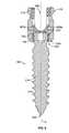
- FIG. 4Ashows a detailed view of a fixation element.
- the fixation element 105can comprise, for example, an elongate screw having a threaded shank 210 with external threads 215 that can be screwed into a bone structure, e.g., pedicle of a vertebra.
- a head 220is positioned at the proximal end of the shank 210 .
- FIG. 4Bshows a close-up view of the head 220 taken along circle 4 B of FIG. 4A .
- the head 220has an upper region 305 and a lower region 310 with a groove 315 therebetween.
- the upper region 305 and lower region 310each has a distal end 3050 , 3150 and a proximal end 3055 , 3155 .
- the distal end 3050 of the upper region 305has a diameter D 1 (which can essentially be equal to the diameter of the proximal end 3155 of the lower region 310 ).
- the groove 315has a diameter D 2 , which is less than D 1 .
- a lip 320overhangs the groove 315 at its proximal end and lip 325 juts out from underneath the groove 315 at its distal end.
- the upper region 305 and the lower region 310are generally curved or spherical in shape, whereas the groove 315 is generally cylindrical in shape. It should be appreciated that other shapes of the upper and lower regions can be used. Similarly, other shapes of the groove can be used.
- the groove 315has a shape that is configured to mate with and receive a correspondingly-shaped clip 115 therein, to be discussed in more detail below.
- a drive couplersuch as a drive cavity 225 (best shown in FIG. 3 ) is located within or on the head 220 of the fixation element 105 .
- the drive cavity 225has a shape that is configured to receive a device that can impart rotational movement to the fixation element 105 in order to screw the fixation element into a bone structure.
- the drive cavity 225can have a hexagonal shape that is configured to receive therein an Allen-style wrench.
- the drive couplerneed not be a cavity that mates with an Allen-style wrench and that other types of drive couplers can be used.
- the fixation element 105can be in forms other than a shank 210 , including, for example, a hook or clamp. Indeed, it should be appreciated that any structure or component configured for attachment to a bone structure can be used in place of the shank 210 of the fixation element 105 .
- the fixation element 105can be made of various materials, including metallic and non-metallic material, depending on the application involved and the stresses expected in vivo.
- the fixation element 105is made of implant grade titanium (Ti-6A1-4V) per ASTM F-136.
- the groove 315 in the head 220 of the fixation element 105has a shape that is configured to mate with and receive the correspondingly-shaped clip 115 therein.
- the clip 115is a generally annular ring having a break 405 in its circumference, wherein the break 405 defines two opposing ring surfaces 410 , 415 .
- the clip 115can also take shapes that are not generally circular.
- the clip 115has an outer diameter D 4 and an inner diameter D 3 . Inner diameter D 3 defines an opening 430 through which a fixation element 105 can be inserted.
- the clip 115has an outer surface 420 and an inner surface 425 .
- the outer surface 420is generally curved or spherical in cross-section, whereas the inner surface 425 is generally flat in cross-section. This cross-section allows the clip 115 to mate with the generally cylindrical shape of the groove 315 at its inner surface 425 and complete the generally rounded shape of the head 220 at its outer surface 420 .
- the clip 115is designed to be at least partially inserted into the groove 315 of the head 220 .
- the height of the groove (Hg)is sufficient to receive the height of the clip (Hc), such that there is little play along axis A or in the up and down direction. Although there is little up and down play between the clip 115 and the groove 315 , the clip 115 can be rotated around axis A inside the groove 315 .
- the width of the clip 115is such that at least a portion of the clip 115 resides inside the groove 315 between upper lip 320 and lower lip 325 and a portion sits outside the groove 315 .
- a portion of the proximal edge 435 of the clip 115abuts the upper lip 320 of the head 220 .
- a portion of the distal edge 440 of the clip 115abuts the lower lip 325 of the head 220 .
- the head 220 with the clip 115 residing in the groove 315is configured to be inserted in the coupling element 110 from the bottom, as described in more detail below. While installed in the groove 315 , the clip 115 can be radially compressed.
- the generally c-shape of the clip 115 and the slightly larger inner diameter D 3 of the clip 115 compared to the groove 315render the clip 115 flexible in the radial direction, also to be discussed in more detail below.
- the clip 115can be compressed until the opposing ring surfaces 410 , 415 meet and the inner surface 425 of the clip 115 approaches the surface of the groove 315 .
- the inner diameter D 3 of the clip 115decreases until it approaches the diameter D 2 of the groove 315 .
- the outer diameter D 4 of the clip 115decreases until it approaches D 1 .
- This compression of the clip 115allows the head to be inserted through the entry port near the bottom of the coupling element 110 into internal bore 505 . Assembly of the device according to a bottom-loading configuration that involves compression of the clip 115 is to be discussed in more detail below.
- the clip 115can resume its original shape such that the ring surfaces 410 , 415 separate and the inner diameter D 3 and outer diameter D 4 return to their original, resting dimensions.
- the radial deformationis within the elastic range of the clip 115 so that no significant permanent deformation of the clip 115 occurs during flexation.
- the clip 115can be made from many materials, including metallic and non-metallic.
- the clip 115is an implant grade titanium (Ti-6A1-4V) per ASTM F-136.
- the clip 115is the same material as the head 220 of the fixation element 105 .
- the coupling element 110is configured to receive a fixation element 105 and an elongate rod 120 .
- the coupling element 110has an internal bore 505 that extends through the coupling element 110 along an axis A and defines entry ports near the bottom and near the top of the coupling element 110 .
- the internal bore 505has a diameter D 5 (best shown in FIG. 7A ) at its entry port nearest the bottom of the coupling element 110 .
- Diameter D 5is at least as large as diameter D 1 , the diameter of the distal end 3050 of the upper region 305 of the head 220 .
- Diameter D 5is less than diameter D 4 , the diameter of the outer surface 420 of the clip 115 in its resting state.
- diameter D 4decreases upon compression of the clip 115 such that diameter D 4 becomes less than diameter D 5 of the internal bore 505 allowing the head 220 of the fixation element 105 to be received therethrough.
- a pair of laterally-opposed, upwardly extending projections 510are separated by the bore 505 .
- the projections 510have internal, threaded surfaces 515 .
- a pair of u-shaped channels 520extend through the coupling element 110 for receiving therein a rod 120 , which can extend along an axis that is transverse to the axis A of the bore 505 .
- the upper ends of the projections 510define an entry port near the top of the coupling element 110 that is sized to receive therein, for example a compression nut 605 , as described below.
- the compression nut 605can have outer threads 610 that are configured to mate with the inner threads on the opposed inner surfaces 515 of the projections 510 of the coupling element 110 .
- the entry portis sized and shaped to facilitate an easy entry of a compression nut 605 into or over the projections 510 of the coupling element 110 .
- a bottom saddle 705 and a top saddle 805are configured to be positioned within the coupling element 110 .
- the saddles 705 , 805each define a contact surface 715 , 815 that has a contour selected to complement a contour of the outer surface of the rod 120 .
- the contact surfaces 715 , 815have rounded contours that complement the rounded, outer surface of the rod 120 .
- the contact surfaces 715 , 815can have any shape or contour that complement the shape and contour of the rod 120 .
- the contact surfaces 715 , 815can also be roughed, serrated, ribbed, or otherwise finished to improve the frictional engagement between the saddles 705 , 805 and the rod 120 .
- the rod 120can also be correspondingly roughed, serrated, ribbed, or otherwise finished to further improve the frictional engagement between saddles 705 , 805 and the rod 120 .
- the complementing shapes and contours between the contact surfaces 715 , 815 and rod 120provide a maximum amount of contact area between the saddles 705 , 805 and rod 120 .
- the rod 120is shown having a rounded or convex outer surface.
- the contact surfaces 715 , 815 of the saddles 705 , 805are correspondingly rounded or concave such that the elongate rod 120 can fit snug between the saddles 705 , 805 with the contact surfaces 715 , 815 of the saddles 705 , 805 providing a wide area of contact with the outer surface of the elongate rod 120 .
- contour and shape of the contact surfaces 715 , 815can be varied to match any contour of the outer surface of the elongate rod 120 or in any manner to maximize the amount of grip between the saddles 705 , 805 and the elongate rod 120 .
- the bottom saddle 705has an internal bore 710 that axially aligns with the bore 505 in the coupling element 110 when the bottom saddle 705 is placed in the coupling element 110 . Furthermore, the bottom saddle 705 has a rounded outer surface that includes a pair of pin cavities 720 positioned, for example, on opposed locations on the bottom saddle 705 . Each of the cavities 720 aligns with a corresponding pin aperture 525 that extends through the coupling element 110 .
- the bottom saddle 705is secured within the coupling element 110 by positioning the saddle 705 between the projections 510 such that each pin cavity 720 in the bottom saddle 705 aligns with a corresponding pin aperture 525 in the coupling element 110 .
- Pins 905 a , 905 bare then inserted through each pin aperture 525 such that one end of each pin 905 a , 905 b pokes into a corresponding pin cavity 720 .
- the pins 905 a , 905 bprovide an interfering engagement with the pin cavities 720 and the pin apertures 525 to thereby secure the bottom saddle 705 in place relative to the coupling element 110 .
- the diameters of the pins 905 a , 905 bcan be smaller than the diameters of the pin cavities 720 so that there is some play therebetween. Furthermore, the pins 905 a , 905 b can have lengths that extend only partially into the pin cavities 720 to provide some play therebetween.
- the bottom saddle 705can also rotate slightly when mounted in the coupling element 110 .
- the bottom saddle 705can movingly adjust into a secure engagement with the elongate rod 120 when compressed against the elongate rod 120 during assembly, as described below.
- the top saddle 805can be rotatingly mounted within a compression nut 605 that has outer threads 610 that are configured to mate with the threads on the internal surface 515 of the opposed projections 810 of the coupling element 110 .
- the top saddle 805has an upper projection 510 that rotatingly mates with the compression nut 605 and permits the top saddle 805 to rotate and/or tilt relative to the compression nut 605 when attached thereto.
- the top saddle 805is positioned immediately below the compression nut 605 .
- the top saddle 805is fixedly attached to the compression nut 605 such that it does not rotate relative to the compression nut 605 .
- the compression nut 605When the compression nut 605 is attached to the top saddle 805 , the compression nut 605 is rotatingly coupled to the coupling element 110 by mating the outer threads 610 of the compression nut 605 with the inner threads 515 of the coupling element 110 .
- the compression nut 605is repeatedly rotated over a 360 degree rotational angle to lower the compression nut 605 into the coupling element 110 .
- the compression nut 605is described herein as having outer threads 610 that mate with inner threads 515 on the opposed projections 510 . As described below, this advantageously permits a thread configuration that prevents projections 510 from spreading apart from one another as the compression nut 605 is screwed into the coupling element 110 .
- the compression nut 605can be modified to have an annular shape with internal threads that mate with corresponding outer threads on the opposed projections 510 .
- the various components of the assembly 100are manufactured of an inert material, such as, for example, stainless steel or titanium.
- the configuration of the clip 115 on the head 220 of the fixation element 105allows for the operator to load the fixation element 105 from the bottom of the coupling element 100 .
- the dimensions of the head 220 without the clip 115 installed in the groove 315are such that the head 220 can be freely inserted through the entry port of the bore 505 nearest the bottom of the coupling element 110 .
- the head 220can just as easily slide back out the bottom of the coupling element 110 without the clip 115 positioned in the head 220 .
- the clip 115retains the head 220 of the fixation element 105 inside the coupling element 110 and prevents it from backing out the bottom of the coupling element 110 .
- the dimensions of the head 220are such that the head 220 can no longer be freely inserted through the entry port of the bore 505 near the bottom of the coupling element 110 .
- Loading the fixation element 105 into the coupling element 110 from the bottominvolves reduction of the outer diameter of the clip 115 by radial compression, to be discussed in more detail below.
- FIG. 7Ashows the clip 115 in a resting state installed in the groove 315 .
- D 1is the diameter of the distal end 3050 of the upper region 305 of the head 220 .
- D 1is essentially equal to the diameter of the proximal end 3155 of the lower region 310 of the head 220 .
- D 1constitutes the widest portion of the head 220 of the fixation element 105 when the clip 115 is not installed.
- D 5is the diameter of the entry port of the internal bore 505 at the bottom of the coupling element 110 .
- D 5is at least as large as D 1 allowing for the head of the screw to be freely inserted when the clip 115 is not installed.
- D 2the diameter of the groove 315 , is less than D 1 .
- D 4is the outer diameter of the clip 115 when in the resting state.
- D 4becomes the widest portion of the head 220 .
- D 4is greater than D 1 and also D 5 . Because D 4 is greater than D 1 and D 5 , the head 220 of the fixation element 105 with the clip 115 installed cannot freely pass through the entry port of the internal bore 505 at the bottom of the coupling element 110 .
- the resting state the head 220 of the fixation element 105 with the clip 115 installedhas a diameter that exceeds the diameter of the bore 505 .
- the clip 115is radially compressed such that D 4 becomes less than D 5 (see FIG. 7B ). As the clip 115 is compressed, the width of the break 405 decreases until the opposing ring surfaces 410 , 415 meet and/or the inner surface 425 of the clip 115 abuts the surface of the groove 315 . D 4 decreases until the head 220 and clip 115 together can be inserted through the entry port at the bottom of the coupling element 110 .
- the clip 115Upon insertion of the head 220 of the fixation element 105 into the coupling element 110 , the clip 115 expands to its dimensions in the resting state. That is, the clip 115 expands such that diameter D 4 is greater than D 5 and the head 220 of the fixation element 105 cannot slide back out the entry port of the coupling element 110 .
- the fixation element 105rests inside the coupling element 110 , the head/clip assembly of which makes contact with a seat 530 near the bottom of the coupling element 110 .
- the seat 530is formed of one or more inclined or slanted surfaces.
- the seat 530can be formed of an annular surface such that the seat 530 is generally conical or the seat 530 can be formed of three or more flat surfaces, such that the seat is pyramidal.
- the seat 530can have any of a variety of shapes adapted to support the head 220 and clip 115 therein.
- the seat 530can be spherical, partially-spherical, conical, frustoconical or other shapes.
- the seat 530is conical or at least partially conical.
- the seat 530supports the rounded head/clip assembly of the fixation element 105 .
- the rounded head/clip assemblyabuts against the seat 530 near the bottom of the coupling element 110 , as shown in the cross-sectional view of FIG. 8 .
- the rounded head/clip assemblycontacts the seat 530 along a contact region that can vary in size and shape.
- the contact regioncan be in the form of a contact circle for example if the seat 530 is conically shaped.
- the rounded head/clip assemblycan be rotated within the seat 530 to move the axis of the shank portion 210 to a desired orientation relative to the coupling element 110 and thereby provide a poly-axial configuration.
- the device 100can be assembled prior to or after driving the fixation element 105 into the bone structure.
- the clip 115can be assembled in the groove 315 of the fixation element 105 prior to or after driving the fixation element 105 into the bone structure.
- the clip 115can be inserted over the top of the head 220 of the fixation element 105 , for example, when the fixation element 105 is already driven into the bone. Because the inner diameter D 3 of the clip 115 is less than the diameter D 1 of the upper region 305 of the head 220 , the clip expands radially in order to pass over the upper region 305 of the head 220 . Once the clip 115 surpasses the upper region 305 of the head 220 , the clip slides past the upper lip 320 into the groove 315 . The groove has a diameter D 2 that is less than the inner diameter D 3 of the clip 115 . Thus, the clip 115 elastically springs in place such that is returns to its original shape inside the groove 315 between lips 320 , 325 .
- the clip 115is installed such that the tip 230 of the fixation element 105 is inserted through the opening 430 in the clip 115 , similar to a washer and screw assembly. Because the inner diameter D 3 of the clip 115 is greater than the diameter of the shank 210 , the clip 115 is easily moved along the length of the fixation element 105 . The clip 115 is passed along the shank 210 of the fixation element 105 until it reaches the lower region 310 of the head 220 . Because the inner diameter D 3 of the clip 115 is less than the diameter of the lower region 310 , the clip radially expands in order to pass over the lower region 310 of the head 220 .
- the radial expansionis allowed due, in part, to the break 405 in the clip 115 .
- the clip 115slides past the lower lip 325 into the groove 315 .
- the groovehas a diameter D 2 that is less than the inner diameter D 3 of the clip 115 .
- the clip 115elastically springs in place such that it returns to it original shape and is retained inside the groove 315 between lips 320 , 325 .
- the clip 115can be radially expanded such that the ends 410 , 415 of the clip 115 spread apart and allow for the clip 115 to be installed directly into the groove 315 of the head 220 instead of past lips 320 or 325 .
- the ends 410 , 415spread apart such that the width of the break 405 expands and approaches the diameter D 2 of the groove 315 .
- the clip 115is then pushed into the groove 315 between lips 320 , 325 and returns to its original shape. A portion of the edge of the clip 115 remains inside the groove 315 and overlaps with lips 320 , 325 .
- the clip 115is compressed until D 4 is less than D 5 .
- the clip 115can be compressed, for example, with a tool such as a pliers-like tool that radially compresses the clip 115 .
- the clip 115is introduced through the top of the coupling element 110 and the head 220 of the fixation element 105 is introduced through the bottom of the coupling element 110 .
- the clip 115is coupled to the head 220 while the head is inside the coupling element 110 . This is accomplished by expending the clip 115 onto the head 220 of the fixation element 105 until it positions into the groove 315 of the head 220 .
- the clip 15then collapses into the groove 315 .
- the head 220 of the fixation element 110is locked in the coupling element 110 such that the head 220 cannot separate from the coupling element 110 .
- the assembled head/clipdoes not fit through the bottom opening in the coupling element 110 .
- the clip 115is compressed until the ends 410 , 415 meet and/or D 3 approaches D 2 .
- the outer diameter D 4 of the clip 114returns to a default diameter that interfaces with the seat to 530 to retain the head 220 within the coupling element 110 .
- the rounded head 220abuts against and sits within a correspondingly-shaped seat 530 in the bottom of the coupling element 110 in a ball/socket manner, as shown in the cross-sectional view of FIG. 8 .
- the seat 530can have a rounded shape that is configured to provide a secure fit between the head/clip assembly and the coupling element 110 . Because the seat 530 is rounded, the head/clip assembly can be rotated within the seat 530 to move the axis of the shank 210 to a desired orientation relative to the coupling element 110 and thereby provide a poly-axial configuration.
- the bottom saddle 705is attached to the coupling element using the pins 905 a , 905 b , which mate with the pin cavities 720 in the side of the bottom saddle 705 .
- the pins 905 a , 905 b and the pin cavities 720there is some play between the pins 905 a , 905 b and the pin cavities 720 , such that the bottom saddle 705 essentially floats and can move somewhat relative to the coupling element 110 . That is, the bottom saddle 705 is attached to the coupling element 110 in a manner that permits movement of the bottom saddle 705 relative to the coupling element 110 and/or relative to the elongate rod 120 .
- the bottom saddle 705adjusts in position as the compression nut 605 is tightened downward into the coupling element 110 , as described below.
- the rod 120is loaded into the coupling element 110 by inserting the rod 120 downwardly between the projections 510 through the unshaped channels 520 . As the rod 120 is moved downwardly into the coupling element 110 , the outer surface of the rod 120 will eventually abut and sit against the corresponding rounded contact surface 715 of the bottom saddle 705 .
- the compression nut 605 and attached upper saddle 805are then threaded downward into the coupling element 110 by mating the external threads 610 on the compression nut 605 with the internal threads 515 on the projections 510 of the coupling element 110 .
- the compression nut 605can be threaded downward until the rod 120 is compressed between the top and bottom saddles 705 , 805 with the compression nut 605 providing the compression force.
- the coupling element 110has an entry port for the compression nut 605 that facilitates entry or coupling of the compression nut 605 into the coupling element 110 .
- the entry portis defined by the upper edges of the projections 510 .
- the entry portcan have a structure that guides the compression nut 605 into a proper engagement with the coupling element 110 .
- one or more large chamferscan be located on the upper, inner edge of the projections 510 of the coupling element 110 to provide ease of entry for the compression nut 605 into the coupling element 110 .
- the chamferscan be angled with the angle being in the range of thirty degrees to sixty degrees relative to vertical axis A, although the angle can vary. The chamfers can help to guide the compression nut 605 into proper alignment with the coupling element 110 such that the threads 610 on the compression nut 605 properly engage the threads on the opposed projections 510 without any cross-threading.
- the compression nut 605is then threaded downwardly by repeatedly rotating the compression nut 605 about a 360 degree rotation.
- the rounded contact surface of the top saddle 805abuts the rod 120 and compresses the rod 120 against the rounded contact surface 715 of the bottom saddle 705 .
- the bottom saddle 705has a floating arrangement with the coupling element 110 and the top saddle 805 is movable and rotatable relative to the compression nut 605 . This permits the saddles 705 , 805 to gradually reposition themselves into a secure purchase with the rod 120 as the compression nut 605 moves downward.
- the contact surface of the saddles 705 , 805provide a continuous and maximized area of contact between the saddles 705 , 805 and the rod 120 for a secure and tight fit therebetween.
- the top saddle 805is shaped so that opposed wings or protrusions 820 are located on opposed sides of the top saddle 805 .
- the opposed protrusions 820are positioned on either side of the rod 120 so as to automatically guide the saddle 805 into alignment with the rod 120 as the saddle 805 lowers onto the rod 120 .
- the protrusions 820will abut opposed sides of the rod 120 as the top saddle 805 is lowered into the coupling element 110 .
- the top saddle 805thus self-aligns into a secure engagement with the rod 120 as the top saddle 805 is lowered onto the rod 120 .
- the protrusions 820 of the top saddle 805are formed by a concave contour of the top saddle contact surface. It should be appreciated that the protrusions 820 need not be formed from curved surfaces, but can also be formed from straight surfaces. Moreover, the protrusions 820 need not be formed from a continuous, elongated surface, but can rather comprise one or more discrete protrusions, such as spikes, that extend downwardly from the top saddle 805 .
- the downward force of the compression nut 605is transferred to the bottom saddle 705 via the top saddle 805 and the rod 120 .
- the head/clip assemblyis thereby pressed downward into the seat 530 in a fixed orientation. In this manner, the position of the fixation element 105 relative to the coupling element 110 is fixed. That is, the head/clip assembly of the fixation element 105 is pressed downward into the seat 530 of the coupling element 110 with a force sufficient to lock the position of the head/clip assembly relative to the coupling element 110 .
- the compression nut 605can be tightened to provide a sufficient downward force that locks the positions of the saddles 705 , 805 relative to the coupling element 110 and the elongate rod 120 .
- the compression nut 605thereby provides a downward force that locks the relative positions of the elongate rod 120 , saddles 705 , 805 , coupling element 110 , and fixation element 105 .
- the upper portion of the opposed projections 510 of the coupling elementcan be snapped off at a predetermined location along the length of the projections 510 .
Landscapes
- Health & Medical Sciences (AREA)
- Orthopedic Medicine & Surgery (AREA)
- Life Sciences & Earth Sciences (AREA)
- Surgery (AREA)
- Neurology (AREA)
- Heart & Thoracic Surgery (AREA)
- Engineering & Computer Science (AREA)
- Biomedical Technology (AREA)
- Nuclear Medicine, Radiotherapy & Molecular Imaging (AREA)
- Medical Informatics (AREA)
- Molecular Biology (AREA)
- Animal Behavior & Ethology (AREA)
- General Health & Medical Sciences (AREA)
- Public Health (AREA)
- Veterinary Medicine (AREA)
- Surgical Instruments (AREA)
Abstract
Description
Claims (5)
Priority Applications (1)
| Application Number | Priority Date | Filing Date | Title |
|---|---|---|---|
| US12/077,940US8657858B2 (en) | 2007-03-26 | 2008-03-21 | Bottom-loading pedicle screw assembly |
Applications Claiming Priority (2)
| Application Number | Priority Date | Filing Date | Title |
|---|---|---|---|
| US92021107P | 2007-03-26 | 2007-03-26 | |
| US12/077,940US8657858B2 (en) | 2007-03-26 | 2008-03-21 | Bottom-loading pedicle screw assembly |
Publications (2)
| Publication Number | Publication Date |
|---|---|
| US20080269809A1 US20080269809A1 (en) | 2008-10-30 |
| US8657858B2true US8657858B2 (en) | 2014-02-25 |
Family
ID=39789176
Family Applications (1)
| Application Number | Title | Priority Date | Filing Date |
|---|---|---|---|
| US12/077,940Active2030-09-25US8657858B2 (en) | 2007-03-26 | 2008-03-21 | Bottom-loading pedicle screw assembly |
Country Status (2)
| Country | Link |
|---|---|
| US (1) | US8657858B2 (en) |
| WO (1) | WO2008118295A2 (en) |
Cited By (20)
| Publication number | Priority date | Publication date | Assignee | Title |
|---|---|---|---|---|
| US20120046700A1 (en)* | 2009-06-15 | 2012-02-23 | Jackson Roger P | Polyaxial bone anchor with pop-on shank and pivotable retainer |
| US20130096622A1 (en)* | 2011-08-18 | 2013-04-18 | Timo Biedermann | Polyaxial bone anchoring device |
| US9907574B2 (en) | 2008-08-01 | 2018-03-06 | Roger P. Jackson | Polyaxial bone anchors with pop-on shank, friction fit fully restrained retainer, insert and tool receiving features |
| US9918745B2 (en) | 2009-06-15 | 2018-03-20 | Roger P. Jackson | Polyaxial bone anchor with pop-on shank and winged insert with friction fit compressive collet |
| US10188431B2 (en) | 2015-12-17 | 2019-01-29 | Deniz Ufuk Erbulut | Double-headed pedicle screw |
| US10265104B2 (en) | 2015-09-23 | 2019-04-23 | Deniz Ufuk Erbulut | Pedicle screw |
| RU195876U1 (en)* | 2019-12-18 | 2020-02-07 | Общество с ограниченной ответственностью "ВИП Технологии" | Pedicular screw |
| US10610265B1 (en) | 2017-07-31 | 2020-04-07 | K2M, Inc. | Polyaxial bone screw with increased angulation |
| US20220168018A1 (en)* | 2007-01-26 | 2022-06-02 | Roger P. Jackson | Dynamic stabilization member |
| US11439437B1 (en) | 2021-06-09 | 2022-09-13 | Medos International Sarl | Bottom loading bone anchor assemblies with drag retaining ring and related methods |
| US11730526B2 (en) | 2019-12-17 | 2023-08-22 | Roger P. Jackson | Bone anchor assembly with ring retainer and internal snap ring |
| US11911075B2 (en) | 2012-01-10 | 2024-02-27 | Roger P. Jackson | Pivotal bone anchor assembly with increased shank angulation |
| US11998247B2 (en) | 2009-06-15 | 2024-06-04 | Roger P. Jackson | Method of assembling a pivotal bone anchor assembly using insert tool deployment |
| US12053209B2 (en) | 2022-01-18 | 2024-08-06 | Roger P. Jackson | Spinal fixation systems with modular receiver and ring retainer sub-assemblies for connecting with universal shank heads |
| US12070249B2 (en) | 2014-06-04 | 2024-08-27 | Jackson Roger P | Pivotal bone anchor assembly with bottom loaded shank head engaging retainer and closure engaging insert |
| US12082853B2 (en) | 2014-10-21 | 2024-09-10 | Roger P. Jackson | Pivotal bone anchor assembly with positioner-retainer containment and insert tool deployment |
| US12082854B2 (en) | 2009-06-15 | 2024-09-10 | Roger P. Jackson | Method of assembling a pivotable bone anchor assembly with a slidable retaining structure |
| US12137945B2 (en) | 2018-09-13 | 2024-11-12 | Roger P. Jackson | Pivotal bone anchor system with modular receiver sub-assemblies and universal bone anchors |
| US12357348B2 (en) | 2005-09-30 | 2025-07-15 | Roger P. Jackson | Method of assembling a pivotal bone anchor assembly with press-in-place insert |
| US12376894B2 (en) | 2005-07-14 | 2025-08-05 | Roger P. Jackson | Pivotal bone anchor assembly with ring retainer and twist-in-place pressure insert |
Families Citing this family (123)
| Publication number | Priority date | Publication date | Assignee | Title |
|---|---|---|---|---|
| US7833250B2 (en) | 2004-11-10 | 2010-11-16 | Jackson Roger P | Polyaxial bone screw with helically wound capture connection |
| US8377100B2 (en) | 2000-12-08 | 2013-02-19 | Roger P. Jackson | Closure for open-headed medical implant |
| US7862587B2 (en) | 2004-02-27 | 2011-01-04 | Jackson Roger P | Dynamic stabilization assemblies, tool set and method |
| US11224464B2 (en) | 2002-05-09 | 2022-01-18 | Roger P. Jackson | Threaded closure with inwardly-facing tool engaging concave radiused structures and axial through-aperture |
| WO2006052796A2 (en) | 2004-11-10 | 2006-05-18 | Jackson Roger P | Helical guide and advancement flange with break-off extensions |
| US8876868B2 (en) | 2002-09-06 | 2014-11-04 | Roger P. Jackson | Helical guide and advancement flange with radially loaded lip |
| US7621918B2 (en) | 2004-11-23 | 2009-11-24 | Jackson Roger P | Spinal fixation tool set and method |
| US6716214B1 (en) | 2003-06-18 | 2004-04-06 | Roger P. Jackson | Polyaxial bone screw with spline capture connection |
| US7377923B2 (en) | 2003-05-22 | 2008-05-27 | Alphatec Spine, Inc. | Variable angle spinal screw assembly |
| US7776067B2 (en) | 2005-05-27 | 2010-08-17 | Jackson Roger P | Polyaxial bone screw with shank articulation pressure insert and method |
| US8377102B2 (en)* | 2003-06-18 | 2013-02-19 | Roger P. Jackson | Polyaxial bone anchor with spline capture connection and lower pressure insert |
| US8398682B2 (en)* | 2003-06-18 | 2013-03-19 | Roger P. Jackson | Polyaxial bone screw assembly |
| US20110040338A1 (en)* | 2003-08-28 | 2011-02-17 | Jackson Roger P | Polyaxial bone anchor having an open retainer with conical, cylindrical or curvate capture |
| US7766915B2 (en) | 2004-02-27 | 2010-08-03 | Jackson Roger P | Dynamic fixation assemblies with inner core and outer coil-like member |
| US20100211114A1 (en)* | 2003-06-18 | 2010-08-19 | Jackson Roger P | Polyaxial bone anchor with shelf capture connection |
| US8926670B2 (en) | 2003-06-18 | 2015-01-06 | Roger P. Jackson | Polyaxial bone screw assembly |
| US7967850B2 (en) | 2003-06-18 | 2011-06-28 | Jackson Roger P | Polyaxial bone anchor with helical capture connection, insert and dual locking assembly |
| US8137386B2 (en) | 2003-08-28 | 2012-03-20 | Jackson Roger P | Polyaxial bone screw apparatus |
| US11419642B2 (en) | 2003-12-16 | 2022-08-23 | Medos International Sarl | Percutaneous access devices and bone anchor assemblies |
| US7527638B2 (en) | 2003-12-16 | 2009-05-05 | Depuy Spine, Inc. | Methods and devices for minimally invasive spinal fixation element placement |
| US7179261B2 (en) | 2003-12-16 | 2007-02-20 | Depuy Spine, Inc. | Percutaneous access devices and bone anchor assemblies |
| JP2007525274A (en) | 2004-02-27 | 2007-09-06 | ロジャー・ピー・ジャクソン | Orthopedic implant rod reduction instrument set and method |
| US7160300B2 (en) | 2004-02-27 | 2007-01-09 | Jackson Roger P | Orthopedic implant rod reduction tool set and method |
| US8152810B2 (en) | 2004-11-23 | 2012-04-10 | Jackson Roger P | Spinal fixation tool set and method |
| US11241261B2 (en) | 2005-09-30 | 2022-02-08 | Roger P Jackson | Apparatus and method for soft spinal stabilization using a tensionable cord and releasable end structure |
| US8951290B2 (en) | 2004-08-27 | 2015-02-10 | Blackstone Medical, Inc. | Multi-axial connection system |
| US8926672B2 (en) | 2004-11-10 | 2015-01-06 | Roger P. Jackson | Splay control closure for open bone anchor |
| US9168069B2 (en) | 2009-06-15 | 2015-10-27 | Roger P. Jackson | Polyaxial bone anchor with pop-on shank and winged insert with lower skirt for engaging a friction fit retainer |
| WO2006057837A1 (en) | 2004-11-23 | 2006-06-01 | Jackson Roger P | Spinal fixation tool attachment structure |
| US9980753B2 (en) | 2009-06-15 | 2018-05-29 | Roger P Jackson | pivotal anchor with snap-in-place insert having rotation blocking extensions |
| US8444681B2 (en) | 2009-06-15 | 2013-05-21 | Roger P. Jackson | Polyaxial bone anchor with pop-on shank, friction fit retainer and winged insert |
| US7875065B2 (en)* | 2004-11-23 | 2011-01-25 | Jackson Roger P | Polyaxial bone screw with multi-part shank retainer and pressure insert |
| US8308782B2 (en) | 2004-11-23 | 2012-11-13 | Jackson Roger P | Bone anchors with longitudinal connecting member engaging inserts and closures for fixation and optional angulation |
| US10076361B2 (en) | 2005-02-22 | 2018-09-18 | Roger P. Jackson | Polyaxial bone screw with spherical capture, compression and alignment and retention structures |
| US7955358B2 (en) | 2005-09-19 | 2011-06-07 | Albert Todd J | Bone screw apparatus, system and method |
| US20080015576A1 (en)* | 2006-04-28 | 2008-01-17 | Whipple Dale E | Large diameter bone anchor assembly |
| US8133262B2 (en) | 2006-04-28 | 2012-03-13 | Depuy Spine, Inc. | Large diameter bone anchor assembly |
| US8361129B2 (en) | 2006-04-28 | 2013-01-29 | Depuy Spine, Inc. | Large diameter bone anchor assembly |
| CA2670988C (en) | 2006-12-08 | 2014-03-25 | Roger P. Jackson | Tool system for dynamic spinal implants |
| US8636783B2 (en) | 2006-12-29 | 2014-01-28 | Zimmer Spine, Inc. | Spinal stabilization systems and methods |
| US10792074B2 (en) | 2007-01-22 | 2020-10-06 | Roger P. Jackson | Pivotal bone anchor assemly with twist-in-place friction fit insert |
| US7942911B2 (en) | 2007-05-16 | 2011-05-17 | Ortho Innovations, Llc | Polyaxial bone screw |
| US7942909B2 (en) | 2009-08-13 | 2011-05-17 | Ortho Innovations, Llc | Thread-thru polyaxial pedicle screw system |
| US7951173B2 (en) | 2007-05-16 | 2011-05-31 | Ortho Innovations, Llc | Pedicle screw implant system |
| US8197518B2 (en) | 2007-05-16 | 2012-06-12 | Ortho Innovations, Llc | Thread-thru polyaxial pedicle screw system |
| US7947065B2 (en) | 2008-11-14 | 2011-05-24 | Ortho Innovations, Llc | Locking polyaxial ball and socket fastener |
| US7942910B2 (en) | 2007-05-16 | 2011-05-17 | Ortho Innovations, Llc | Polyaxial bone screw |
| ES2348814T3 (en) | 2007-07-31 | 2010-12-15 | Biedermann Motech Gmbh | ANCHORAGE DEVICE Ã “SEO. |
| EP2242437B1 (en)* | 2008-01-24 | 2014-03-26 | Globus Medical, Inc. | Facet fixation prosthesis |
| US8007522B2 (en) | 2008-02-04 | 2011-08-30 | Depuy Spine, Inc. | Methods for correction of spinal deformities |
| WO2009132302A1 (en) | 2008-04-25 | 2009-10-29 | Pioneer Surgical Technology, Inc. | Bone plate system |
| US8075603B2 (en) | 2008-11-14 | 2011-12-13 | Ortho Innovations, Llc | Locking polyaxial ball and socket fastener |
| ES2548580T3 (en) | 2009-02-20 | 2015-10-19 | Biedermann Technologies Gmbh & Co. Kg | Receiving part for housing a rod for coupling to a bone anchoring element and bone anchoring device that includes such receiving part |
| US8241341B2 (en) | 2009-03-20 | 2012-08-14 | Spinal Usa, Inc. | Pedicle screws and methods of using the same |
| US11464549B2 (en) | 2009-06-15 | 2022-10-11 | Roger P. Jackson | Pivotal bone anchor assembly with horizontal tool engagement grooves and insert with upright arms having flared outer portions |
| US9668771B2 (en) | 2009-06-15 | 2017-06-06 | Roger P Jackson | Soft stabilization assemblies with off-set connector |
| US8998959B2 (en) | 2009-06-15 | 2015-04-07 | Roger P Jackson | Polyaxial bone anchors with pop-on shank, fully constrained friction fit retainer and lock and release insert |
| US8236035B1 (en) | 2009-06-16 | 2012-08-07 | Bedor Bernard M | Spinal fixation system and method |
| EP2283786B1 (en) | 2009-08-12 | 2015-06-17 | Biedermann Technologies GmbH & Co. KG | A receiving part for receiving a rod for coupling the rod to a bone anchoring element |
| EP2485654B1 (en) | 2009-10-05 | 2021-05-05 | Jackson P. Roger | Polyaxial bone anchor with non-pivotable retainer and pop-on shank, some with friction fit |
| US8361123B2 (en) | 2009-10-16 | 2013-01-29 | Depuy Spine, Inc. | Bone anchor assemblies and methods of manufacturing and use thereof |
| US8449578B2 (en)* | 2009-11-09 | 2013-05-28 | Ebi, Llc | Multiplanar bone anchor system |
| US9044272B2 (en)* | 2009-11-09 | 2015-06-02 | Ebi, Llc | Multiplanar bone anchor system |
| EP2606842B1 (en)* | 2010-03-29 | 2018-08-29 | Biedermann Technologies GmbH & Co. KG | Bone anchoring device |
| US12383311B2 (en) | 2010-05-14 | 2025-08-12 | Roger P. Jackson | Pivotal bone anchor assembly and method for use thereof |
| US8641717B2 (en) | 2010-07-01 | 2014-02-04 | DePuy Synthes Products, LLC | Guidewire insertion methods and devices |
| WO2012030712A1 (en) | 2010-08-30 | 2012-03-08 | Zimmer Spine, Inc. | Polyaxial pedicle screw |
| US10111694B2 (en) | 2010-10-05 | 2018-10-30 | Skeletal Design Partnership, Llc | Pedicle screw assembly and method of assembly |
| EP2637584A4 (en)* | 2010-10-15 | 2015-01-28 | Alphatec Holdings Inc | FIXING SCREW ASSEMBLY |
| ES2461843T3 (en)* | 2010-12-23 | 2014-05-21 | Biedermann Technologies Gmbh & Co. Kg | Bone anchoring device |
| EP2659845A1 (en) | 2010-12-27 | 2013-11-06 | Biedermann Technologies GmbH & Co. KG | Polyaxial bone anchoring device |
| JP5865479B2 (en) | 2011-03-24 | 2016-02-17 | ロジャー・ピー・ジャクソン | Multiaxial bone anchor with compound joint and pop-mounted shank |
| EP2559391B1 (en)* | 2011-08-18 | 2014-06-18 | Biedermann Technologies GmbH & Co. KG | Polyaxial bone anchoring system |
| ES2504067T3 (en)* | 2011-08-18 | 2014-10-08 | Biedermann Technologies Gmbh & Co. Kg | Polyaxial bone anchoring device with extended turning angle |
| US8663290B2 (en) | 2011-10-28 | 2014-03-04 | Ortho Innovations, Llc | Top loading polyaxial ball and socket fastener with saddle |
| US8663291B2 (en) | 2011-10-28 | 2014-03-04 | Ortho Innovations, Llc | Top loading polyaxial ball and socket fastener |
| US9060814B2 (en) | 2011-10-28 | 2015-06-23 | Ortho Innovations, Llc | Spring clip bottom loading polyaxial ball and socket fastener |
| US9198769B2 (en) | 2011-12-23 | 2015-12-01 | Pioneer Surgical Technology, Inc. | Bone anchor assembly, bone plate system, and method |
| ES2527766T3 (en) | 2012-05-29 | 2015-01-29 | Biedermann Technologies Gmbh & Co. Kg | Receiver piece for receiving and housing a bar in order to couple it with a bone anchoring element, and bone anchoring device with such a receiving piece |
| US9782204B2 (en) | 2012-09-28 | 2017-10-10 | Medos International Sarl | Bone anchor assemblies |
| US8911478B2 (en) | 2012-11-21 | 2014-12-16 | Roger P. Jackson | Splay control closure for open bone anchor |
| US10058354B2 (en) | 2013-01-28 | 2018-08-28 | Roger P. Jackson | Pivotal bone anchor assembly with frictional shank head seating surfaces |
| US20140214084A1 (en)* | 2013-01-28 | 2014-07-31 | Roger P. Jackson | Polyaxial bone anchor with receiver with spheric edge for friction fit |
| US20220160402A1 (en)* | 2013-02-09 | 2022-05-26 | Vertiscrew, Llc | Bone screw |
| US9579125B2 (en)* | 2013-02-09 | 2017-02-28 | Vertiscrew, Llc | Bone screw |
| EP2764840B1 (en)* | 2013-02-11 | 2017-05-03 | Biedermann Technologies GmbH & Co. KG | Coupling assembly for coupling a rod to a bone anchoring element and bone anchoring device with such a coupling assembly |
| US8852239B2 (en) | 2013-02-15 | 2014-10-07 | Roger P Jackson | Sagittal angle screw with integral shank and receiver |
| US9005205B2 (en) | 2013-03-04 | 2015-04-14 | Degen Medical, Inc. | Rod insertion tools, rods and methods |
| US9259247B2 (en) | 2013-03-14 | 2016-02-16 | Medos International Sarl | Locking compression members for use with bone anchor assemblies and methods |
| US20140277159A1 (en) | 2013-03-14 | 2014-09-18 | DePuy Synthes Products, LLC | Bottom-loading bone anchor assemblies |
| US10342582B2 (en) | 2013-03-14 | 2019-07-09 | DePuy Synthes Products, Inc. | Bone anchor assemblies and methods with improved locking |
| US9724145B2 (en) | 2013-03-14 | 2017-08-08 | Medos International Sarl | Bone anchor assemblies with multiple component bottom loading bone anchors |
| US20140277153A1 (en) | 2013-03-14 | 2014-09-18 | DePuy Synthes Products, LLC | Bone Anchor Assemblies and Methods With Improved Locking |
| US9775660B2 (en) | 2013-03-14 | 2017-10-03 | DePuy Synthes Products, Inc. | Bottom-loading bone anchor assemblies and methods |
| US9433445B2 (en) | 2013-03-14 | 2016-09-06 | DePuy Synthes Products, Inc. | Bone anchors and surgical instruments with integrated guide tips |
| US9655659B2 (en) | 2013-04-20 | 2017-05-23 | Degen Medical, Inc. | Anchor tower |
| US9453526B2 (en) | 2013-04-30 | 2016-09-27 | Degen Medical, Inc. | Bottom-loading anchor assembly |
| EP3021771A1 (en) | 2013-07-18 | 2016-05-25 | Ortho Innovations, LLC | Spring clip bottom loading polyaxial ball and socket fastener |
| US9566092B2 (en) | 2013-10-29 | 2017-02-14 | Roger P. Jackson | Cervical bone anchor with collet retainer and outer locking sleeve |
| US9717533B2 (en) | 2013-12-12 | 2017-08-01 | Roger P. Jackson | Bone anchor closure pivot-splay control flange form guide and advancement structure |
| US10030694B2 (en)* | 2013-12-17 | 2018-07-24 | Ingersoll-Rand Company | Adjustable joints |
| US9451993B2 (en) | 2014-01-09 | 2016-09-27 | Roger P. Jackson | Bi-radial pop-on cervical bone anchor |
| ES2602982T3 (en)* | 2014-01-13 | 2017-02-23 | Biedermann Technologies Gmbh & Co. Kg | Coupling set for coupling a rod with a bone anchoring element, and polyaxial bone anchoring device |
| US10561453B2 (en)* | 2015-03-11 | 2020-02-18 | Warsaw Orthopedic, Inc. | Bone fastener and methods of use |
| US9597119B2 (en) | 2014-06-04 | 2017-03-21 | Roger P. Jackson | Polyaxial bone anchor with polymer sleeve |
| EP3209220B1 (en)* | 2014-10-21 | 2019-09-25 | Roger P. Jackson | Snap-on multi-planar and mono-planar receiver assemblies having integral and multi-part multipurpose positioners for pivoting and non-pivoting retainers |
| US11219471B2 (en) | 2014-10-21 | 2022-01-11 | Roger P. Jackson | Pivotal bone anchor receiver having an insert with post-placement tool deployment |
| US9924975B2 (en) | 2014-10-21 | 2018-03-27 | Roger P. Jackson | Bone anchor having a snap-fit assembly |
| US9707013B2 (en)* | 2015-04-30 | 2017-07-18 | Warsaw Orthopedic, Inc. | Spinal implant system and methods of use |
| WO2017059941A1 (en)* | 2015-10-06 | 2017-04-13 | Joimax Gmbh | Device for securing a rod to a bone |
| US11389205B2 (en)* | 2016-11-30 | 2022-07-19 | Stryker European Operations Holdings Llc | Spinal fastener with serrated thread |
| USD898196S1 (en) | 2017-07-10 | 2020-10-06 | Stryker European Holdings I, Llc | Spinal fastener with serrated thread |
| US20190175224A1 (en) | 2017-12-12 | 2019-06-13 | Spinal Llc | Spring clip bottom loading polyaxial ball and socket fastener |
| US10258385B1 (en) | 2017-12-12 | 2019-04-16 | Spinal Llc | Bottom loading polyaxial ball and socket fastener with blocking ring with notched split ring |
| EP3510954B1 (en)* | 2018-01-10 | 2021-07-28 | Biedermann Technologies GmbH & Co. KG | Polyaxial bone anchoring device and system of an instrument and a polyaxial bone anchoring device |
| US20190388124A1 (en)* | 2018-06-22 | 2019-12-26 | Astura Medical Inc. | Uniplanar screw |
| US11490932B2 (en) | 2018-11-01 | 2022-11-08 | Next Orthosurgical, Inc. | Polyaxial pedicle screw system |
| EP3766443B1 (en) | 2019-07-18 | 2023-02-15 | Biedermann Technologies GmbH & Co. KG | Bone anchoring device |
| EP3831322B1 (en)* | 2019-12-06 | 2025-03-19 | Biedermann Technologies GmbH & Co. KG | Coupling device for coupling a rod to a bone anchor |
| EP3871624B1 (en) | 2020-02-25 | 2023-07-19 | Biedermann Technologies GmbH & Co. KG | Bone anchoring device |
| WO2022184797A1 (en) | 2021-03-05 | 2022-09-09 | Medos International Sarl | Selectively locking polyaxial screw |
| US20240325055A1 (en)* | 2023-03-30 | 2024-10-03 | Orthofix Us Llc | Friction-fit implantable devices and assemblies |
| US20250221749A1 (en)* | 2023-10-12 | 2025-07-10 | Luis Duarte | Surgical Fixation System and Related Methods |
Citations (26)
| Publication number | Priority date | Publication date | Assignee | Title |
|---|---|---|---|---|
| US5534027A (en) | 1993-06-21 | 1996-07-09 | Zimmer, Inc. | Method for providing a barrier to the advancement of wear debris in an orthopaedic implant assembly |
| US5578034A (en)* | 1995-06-07 | 1996-11-26 | Danek Medical, Inc. | Apparatus for preventing screw backout in a bone plate fixation system |
| US5876402A (en) | 1995-04-13 | 1999-03-02 | Errico; Joseph P. | Anterior spinal polyaxial locking screw plate assembly having recessed retaining rings |
| US5891145A (en) | 1997-07-14 | 1999-04-06 | Sdgi Holdings, Inc. | Multi-axial screw |
| US5931838A (en) | 1997-01-28 | 1999-08-03 | Vito; Raymond P. | Fixation assembly for orthopedic applications |
| US6059785A (en) | 1993-12-07 | 2000-05-09 | Synthes (U.S.A.) | Bone fixation device |
| US6063090A (en) | 1996-12-12 | 2000-05-16 | Synthes (U.S.A.) | Device for connecting a longitudinal support to a pedicle screw |
| US6113601A (en) | 1998-06-12 | 2000-09-05 | Bones Consulting, Llc | Polyaxial pedicle screw having a loosely coupled locking cap |
| US6241731B1 (en) | 1998-08-11 | 2001-06-05 | Daniel Fiz | Plate and screw assembly for fixing bones |
| US6261291B1 (en) | 1999-07-08 | 2001-07-17 | David J. Talaber | Orthopedic implant assembly |
| US6280442B1 (en) | 1999-09-01 | 2001-08-28 | Sdgi Holdings, Inc. | Multi-axial bone screw assembly |
| US6331179B1 (en) | 2000-01-06 | 2001-12-18 | Spinal Concepts, Inc. | System and method for stabilizing the human spine with a bone plate |
| US6485491B1 (en) | 2000-09-15 | 2002-11-26 | Sdgi Holdings, Inc. | Posterior fixation system |
| US6602255B1 (en) | 2000-06-26 | 2003-08-05 | Stryker Spine | Bone screw retaining system |
| US6613053B1 (en) | 2001-10-25 | 2003-09-02 | Corin Limited | Surgical implant |
| US6663635B2 (en) | 1999-07-07 | 2003-12-16 | Synthes (U.S.A.) | Bone screw with two-part screw head |
| US6716214B1 (en) | 2003-06-18 | 2004-04-06 | Roger P. Jackson | Polyaxial bone screw with spline capture connection |
| US20040097933A1 (en) | 2002-11-19 | 2004-05-20 | Rodolphe Lourdel | Vertebral anchoring device and its blocking device on a polyaxial screw |
| US20050049593A1 (en)* | 2003-09-03 | 2005-03-03 | Duong Lan Anh Nguyen | Bone plate with captive clips |
| US20050261687A1 (en) | 2004-04-20 | 2005-11-24 | Laszlo Garamszegi | Pedicle screw assembly |
| US7001389B1 (en) | 2002-07-05 | 2006-02-21 | Navarro Richard R | Fixed and variable locking fixation assembly |
| US7048739B2 (en) | 2002-12-31 | 2006-05-23 | Depuy Spine, Inc. | Bone plate and resilient screw system allowing bi-directional assembly |
| US20060142761A1 (en)* | 2002-10-30 | 2006-06-29 | Landry Michael E | Spinal stabilization systems and methods |
| US7087057B2 (en) | 2003-06-27 | 2006-08-08 | Depuy Acromed, Inc. | Polyaxial bone screw |
| US20070270813A1 (en) | 2006-04-12 | 2007-11-22 | Laszlo Garamszegi | Pedicle screw assembly |
| US20080045953A1 (en) | 2006-07-14 | 2008-02-21 | Laszlo Garamszegi | Pedicle screw assembly with inclined surface seat |
Family Cites Families (2)
| Publication number | Priority date | Publication date | Assignee | Title |
|---|---|---|---|---|
| US7635367B2 (en)* | 2003-08-05 | 2009-12-22 | Medicrea International | Osteosynthesis clip and insertion tool for use with bone tissue fragments |
| US7909826B2 (en)* | 2005-03-24 | 2011-03-22 | Depuy Spine, Inc. | Low profile spinal tethering methods |
- 2008
- 2008-03-15WOPCT/US2008/003392patent/WO2008118295A2/enactiveApplication Filing
- 2008-03-21USUS12/077,940patent/US8657858B2/enactiveActive
Patent Citations (29)
| Publication number | Priority date | Publication date | Assignee | Title |
|---|---|---|---|---|
| US5534027A (en) | 1993-06-21 | 1996-07-09 | Zimmer, Inc. | Method for providing a barrier to the advancement of wear debris in an orthopaedic implant assembly |
| US6059785A (en) | 1993-12-07 | 2000-05-09 | Synthes (U.S.A.) | Bone fixation device |
| US5876402A (en) | 1995-04-13 | 1999-03-02 | Errico; Joseph P. | Anterior spinal polyaxial locking screw plate assembly having recessed retaining rings |
| US5578034A (en)* | 1995-06-07 | 1996-11-26 | Danek Medical, Inc. | Apparatus for preventing screw backout in a bone plate fixation system |
| US6063090A (en) | 1996-12-12 | 2000-05-16 | Synthes (U.S.A.) | Device for connecting a longitudinal support to a pedicle screw |
| US5931838A (en) | 1997-01-28 | 1999-08-03 | Vito; Raymond P. | Fixation assembly for orthopedic applications |
| US5891145A (en) | 1997-07-14 | 1999-04-06 | Sdgi Holdings, Inc. | Multi-axial screw |
| US6113601A (en) | 1998-06-12 | 2000-09-05 | Bones Consulting, Llc | Polyaxial pedicle screw having a loosely coupled locking cap |
| US6241731B1 (en) | 1998-08-11 | 2001-06-05 | Daniel Fiz | Plate and screw assembly for fixing bones |
| US6663635B2 (en) | 1999-07-07 | 2003-12-16 | Synthes (U.S.A.) | Bone screw with two-part screw head |
| US6261291B1 (en) | 1999-07-08 | 2001-07-17 | David J. Talaber | Orthopedic implant assembly |
| US6280442B1 (en) | 1999-09-01 | 2001-08-28 | Sdgi Holdings, Inc. | Multi-axial bone screw assembly |
| US20020026193A1 (en) | 1999-09-01 | 2002-02-28 | B. Thomas Barker | Multi-axial bone screw assembly |
| US20040116929A1 (en) | 1999-09-01 | 2004-06-17 | Barker B. Thomas | Multi-axial bone screw assembly |
| US6331179B1 (en) | 2000-01-06 | 2001-12-18 | Spinal Concepts, Inc. | System and method for stabilizing the human spine with a bone plate |
| US6602255B1 (en) | 2000-06-26 | 2003-08-05 | Stryker Spine | Bone screw retaining system |
| US6485491B1 (en) | 2000-09-15 | 2002-11-26 | Sdgi Holdings, Inc. | Posterior fixation system |
| US6613053B1 (en) | 2001-10-25 | 2003-09-02 | Corin Limited | Surgical implant |
| US7001389B1 (en) | 2002-07-05 | 2006-02-21 | Navarro Richard R | Fixed and variable locking fixation assembly |
| US20060142761A1 (en)* | 2002-10-30 | 2006-06-29 | Landry Michael E | Spinal stabilization systems and methods |
| US20040097933A1 (en) | 2002-11-19 | 2004-05-20 | Rodolphe Lourdel | Vertebral anchoring device and its blocking device on a polyaxial screw |
| US7048739B2 (en) | 2002-12-31 | 2006-05-23 | Depuy Spine, Inc. | Bone plate and resilient screw system allowing bi-directional assembly |
| US6716214B1 (en) | 2003-06-18 | 2004-04-06 | Roger P. Jackson | Polyaxial bone screw with spline capture connection |
| US8257396B2 (en)* | 2003-06-18 | 2012-09-04 | Jackson Roger P | Polyaxial bone screw with shank-retainer inset capture |
| US7087057B2 (en) | 2003-06-27 | 2006-08-08 | Depuy Acromed, Inc. | Polyaxial bone screw |
| US20050049593A1 (en)* | 2003-09-03 | 2005-03-03 | Duong Lan Anh Nguyen | Bone plate with captive clips |
| US20050261687A1 (en) | 2004-04-20 | 2005-11-24 | Laszlo Garamszegi | Pedicle screw assembly |
| US20070270813A1 (en) | 2006-04-12 | 2007-11-22 | Laszlo Garamszegi | Pedicle screw assembly |
| US20080045953A1 (en) | 2006-07-14 | 2008-02-21 | Laszlo Garamszegi | Pedicle screw assembly with inclined surface seat |
Cited By (28)
| Publication number | Priority date | Publication date | Assignee | Title |
|---|---|---|---|---|
| US12376894B2 (en) | 2005-07-14 | 2025-08-05 | Roger P. Jackson | Pivotal bone anchor assembly with ring retainer and twist-in-place pressure insert |
| US12357348B2 (en) | 2005-09-30 | 2025-07-15 | Roger P. Jackson | Method of assembling a pivotal bone anchor assembly with press-in-place insert |
| US20220168018A1 (en)* | 2007-01-26 | 2022-06-02 | Roger P. Jackson | Dynamic stabilization member |
| US12376886B2 (en) | 2008-08-01 | 2025-08-05 | Roger P. Jackson | Pivotal bone anchor assembly with retainer pre-positioned in expansion chamber and tool-deployable insert |
| US9907574B2 (en) | 2008-08-01 | 2018-03-06 | Roger P. Jackson | Polyaxial bone anchors with pop-on shank, friction fit fully restrained retainer, insert and tool receiving features |
| US9918745B2 (en) | 2009-06-15 | 2018-03-20 | Roger P. Jackson | Polyaxial bone anchor with pop-on shank and winged insert with friction fit compressive collet |
| US20120046700A1 (en)* | 2009-06-15 | 2012-02-23 | Jackson Roger P | Polyaxial bone anchor with pop-on shank and pivotable retainer |
| US10363070B2 (en)* | 2009-06-15 | 2019-07-30 | Roger P. Jackson | Pivotal bone anchor assemblies with pressure inserts and snap on articulating retainers |
| US12207847B2 (en) | 2009-06-15 | 2025-01-28 | Roger P. Jackson | Modular pivotal bone anchor assembly having pre-loaded insert engageable with restrained pre-loaded expandable retainer |
| US12082854B2 (en) | 2009-06-15 | 2024-09-10 | Roger P. Jackson | Method of assembling a pivotable bone anchor assembly with a slidable retaining structure |
| US11998247B2 (en) | 2009-06-15 | 2024-06-04 | Roger P. Jackson | Method of assembling a pivotal bone anchor assembly using insert tool deployment |
| US9345516B2 (en)* | 2011-08-18 | 2016-05-24 | Biedermann Technologies Gmbh & Co. Kg | Polyaxial bone anchoring device |
| US20130096622A1 (en)* | 2011-08-18 | 2013-04-18 | Timo Biedermann | Polyaxial bone anchoring device |
| US11911075B2 (en) | 2012-01-10 | 2024-02-27 | Roger P. Jackson | Pivotal bone anchor assembly with increased shank angulation |
| US12070249B2 (en) | 2014-06-04 | 2024-08-27 | Jackson Roger P | Pivotal bone anchor assembly with bottom loaded shank head engaging retainer and closure engaging insert |
| US12167872B2 (en) | 2014-10-21 | 2024-12-17 | Roger P. Jackson | Bottom loaded pivotal bone anchor assembly with locking and blocking rings and insert tool deployment |
| US12082853B2 (en) | 2014-10-21 | 2024-09-10 | Roger P. Jackson | Pivotal bone anchor assembly with positioner-retainer containment and insert tool deployment |
| US10265104B2 (en) | 2015-09-23 | 2019-04-23 | Deniz Ufuk Erbulut | Pedicle screw |
| US10188431B2 (en) | 2015-12-17 | 2019-01-29 | Deniz Ufuk Erbulut | Double-headed pedicle screw |
| US10610265B1 (en) | 2017-07-31 | 2020-04-07 | K2M, Inc. | Polyaxial bone screw with increased angulation |
| US11229459B2 (en) | 2017-07-31 | 2022-01-25 | K2M, Inc. | Polyaxial bone screw with increased angulation |
| US12262923B2 (en) | 2017-07-31 | 2025-04-01 | K2M, Inc. | Polyaxial bone screw with increased angulation |
| US12137945B2 (en) | 2018-09-13 | 2024-11-12 | Roger P. Jackson | Pivotal bone anchor system with modular receiver sub-assemblies and universal bone anchors |
| US11730526B2 (en) | 2019-12-17 | 2023-08-22 | Roger P. Jackson | Bone anchor assembly with ring retainer and internal snap ring |
| RU195876U1 (en)* | 2019-12-18 | 2020-02-07 | Общество с ограниченной ответственностью "ВИП Технологии" | Pedicular screw |
| US12201327B2 (en) | 2021-06-09 | 2025-01-21 | Medos International Sárl | Bottom loading bone anchor assemblies with drag retaining ring and related methods |
| US11439437B1 (en) | 2021-06-09 | 2022-09-13 | Medos International Sarl | Bottom loading bone anchor assemblies with drag retaining ring and related methods |
| US12053209B2 (en) | 2022-01-18 | 2024-08-06 | Roger P. Jackson | Spinal fixation systems with modular receiver and ring retainer sub-assemblies for connecting with universal shank heads |
Also Published As
| Publication number | Publication date |
|---|---|
| WO2008118295A2 (en) | 2008-10-02 |
| US20080269809A1 (en) | 2008-10-30 |
| WO2008118295A3 (en) | 2008-11-27 |
Similar Documents
| Publication | Publication Date | Title |
|---|---|---|
| US8657858B2 (en) | Bottom-loading pedicle screw assembly | |
| US8480711B2 (en) | Pedicle screw assembly with inclined surface seat | |
| US8915945B2 (en) | Adjustable multi-axial spinal coupling assemblies | |
| US20240032969A1 (en) | Multipoint fixation implants | |
| US20070270813A1 (en) | Pedicle screw assembly | |
| US8518085B2 (en) | Adaptive spinal rod and methods for stabilization of the spine | |
| US8075599B2 (en) | Adjustable bone anchor assembly | |
| CN101098661B (en) | Side Loaded Vertebral Anchor | |
| US8430917B2 (en) | Bone engaging implant with adjustment saddle | |
| EP1922002B1 (en) | Coupling assemblies for spinal implants | |
| US20110270321A1 (en) | Engaging Member With a Cavity-Base for Engaging a Connecting Element to a Bone Anchor | |
| US20050240181A1 (en) | Spinal implant connectors | |
| AU2019291788A1 (en) | Length adjustable modular screw system | |
| US20100168796A1 (en) | Bone anchoring member with clamp mechanism | |
| JP2009511171A (en) | Multi-directional moving device for fixing the spine during osteosynthesis surgery | |
| US20060052783A1 (en) | Polyaxial device for spine stabilization during osteosynthesis | |
| US20110257690A1 (en) | Transverse and Sagittal Adjusting Screw | |
| US20120035667A1 (en) | Locking mechanisms for pivoting bone anchors | |
| US12256962B2 (en) | Multipoint fixation implants and related methods | |
| JP2009512466A (en) | Multi-axis screw | |
| EP0746255A1 (en) | Transverse link for spinal implant system | |
| US20140343613A1 (en) | Bone anchoring member with clamp mechanism | |
| JP2009517174A (en) | Side mounted adjustable bone anchor | |
| JP7456588B1 (en) | spinal stabilization system |
Legal Events
| Date | Code | Title | Description |
|---|---|---|---|
| AS | Assignment | Owner name:ALLEZ SPINE, LLC, CALIFORNIA Free format text:ASSIGNMENT OF ASSIGNORS INTEREST;ASSIGNOR:GARAMSZEGI, LASZLO;REEL/FRAME:021241/0270 Effective date:20080707 | |
| AS | Assignment | Owner name:PHYGEN, LLC, CALIFORNIA Free format text:CHANGE OF NAME;ASSIGNOR:ALLEZ SPINE, LLC;REEL/FRAME:027615/0719 Effective date:20090807 | |
| AS | Assignment | Owner name:ALPHATEC SPINE, INC., CALIFORNIA Free format text:ASSIGNMENT OF ASSIGNORS INTEREST;ASSIGNOR:PHYGEN, LLC;REEL/FRAME:029492/0665 Effective date:20121105 | |
| AS | Assignment | Owner name:MIDCAP FUNDING IV, LLC, AS SUCCESSOR-BY-ASSIGNMENT Free format text:FIRST AMENDMENT TO SECURITY AGREEMENT;ASSIGNORS:ALPHATEC HOLDINGS, INC.;ALPHATEC SPINE, INC.;ALPHATEC INTERNATIONAL LLC;AND OTHERS;REEL/FRAME:029943/0512 Effective date:20130226 | |
| STCF | Information on status: patent grant | Free format text:PATENTED CASE | |
| AS | Assignment | Owner name:DEERFIELD PRIVATE DESIGN FUND II, L.P., NEW YORK Free format text:SECURITY INTEREST;ASSIGNORS:ALPHATEC HOLDINGS, INC.;ALPHATEC SPINE, INC.;ALPHATEC INTERNATIONAL LLC;AND OTHERS;REEL/FRAME:032551/0037 Effective date:20140317 Owner name:DEERFIELD SPECIAL SITUATIONS FUND, L.P., NEW YORK Free format text:SECURITY INTEREST;ASSIGNORS:ALPHATEC HOLDINGS, INC.;ALPHATEC SPINE, INC.;ALPHATEC INTERNATIONAL LLC;AND OTHERS;REEL/FRAME:032551/0037 Effective date:20140317 Owner name:DEERFIELD PRIVATE DESIGN INTERNATIONAL II, L.P., N Free format text:SECURITY INTEREST;ASSIGNORS:ALPHATEC HOLDINGS, INC.;ALPHATEC SPINE, INC.;ALPHATEC INTERNATIONAL LLC;AND OTHERS;REEL/FRAME:032551/0037 Effective date:20140317 Owner name:DEERFIELD SPECIAL SITUATIONS INTERNATIONAL MASTER Free format text:SECURITY INTEREST;ASSIGNORS:ALPHATEC HOLDINGS, INC.;ALPHATEC SPINE, INC.;ALPHATEC INTERNATIONAL LLC;AND OTHERS;REEL/FRAME:032551/0037 Effective date:20140317 | |
| AS | Assignment | Owner name:ALPHATEC INTERNATIONAL LLC, CALIFORNIA Free format text:RELEASE BY SECURED PARTY;ASSIGNORS:DEERFIELD PRIVATE DESIGN FUND II, L.P.;DEERFIELD PRIVATE DESIGN INTERNATIONAL II, L.P.;DEERFIELD SPECIAL SITUATIONS FUND, L.P.;AND OTHERS;REEL/FRAME:039950/0360 Effective date:20160901 Owner name:ALPHATEC SPINE, INC., CALIFORNIA Free format text:RELEASE BY SECURED PARTY;ASSIGNORS:DEERFIELD PRIVATE DESIGN FUND II, L.P.;DEERFIELD PRIVATE DESIGN INTERNATIONAL II, L.P.;DEERFIELD SPECIAL SITUATIONS FUND, L.P.;AND OTHERS;REEL/FRAME:039950/0360 Effective date:20160901 Owner name:ALPHATEC HOLDINGS, INC., CALIFORNIA Free format text:RELEASE BY SECURED PARTY;ASSIGNORS:DEERFIELD PRIVATE DESIGN FUND II, L.P.;DEERFIELD PRIVATE DESIGN INTERNATIONAL II, L.P.;DEERFIELD SPECIAL SITUATIONS FUND, L.P.;AND OTHERS;REEL/FRAME:039950/0360 Effective date:20160901 Owner name:ALPHATEC PACIFIC, INC., CALIFORNIA Free format text:RELEASE BY SECURED PARTY;ASSIGNORS:DEERFIELD PRIVATE DESIGN FUND II, L.P.;DEERFIELD PRIVATE DESIGN INTERNATIONAL II, L.P.;DEERFIELD SPECIAL SITUATIONS FUND, L.P.;AND OTHERS;REEL/FRAME:039950/0360 Effective date:20160901 | |
| AS | Assignment | Owner name:GLOBUS MEDICAL, INC., PENNSYLVANIA Free format text:INTELLECTUAL PROPERTY SECURITY AGREEMENT;ASSIGNORS:ALPHATEC HOLDINGS, INC.;ALPHATEC SPINE, INC.;REEL/FRAME:040108/0202 Effective date:20160901 | |
| AS | Assignment | Owner name:PHYGEN, LLC, CALIFORNIA Free format text:ASSIGNMENT OF ASSIGNORS INTEREST;ASSIGNOR:ALPHATEC SPINE, INC.;REEL/FRAME:042504/0435 Effective date:20170505 | |
| AS | Assignment | Owner name:PHYGEN, LLC, CALIFORNIA Free format text:RELEASE BY SECURED PARTY;ASSIGNOR:GLOBUS MEDICAL, INC.;REEL/FRAME:043108/0597 Effective date:20170725 | |
| MAFP | Maintenance fee payment | Free format text:PAYMENT OF MAINTENANCE FEE, 4TH YR, SMALL ENTITY (ORIGINAL EVENT CODE: M2551) Year of fee payment:4 | |
| AS | Assignment | Owner name:ALPHATEC SPINE, INC., CALIFORNIA Free format text:RELEASE BY SECURED PARTY;ASSIGNOR:MIDCAP FUNDING IV TRUST;REEL/FRAME:043687/0138 Effective date:20170808 | |
| AS | Assignment | Owner name:ALPHATEC SPINE, INC., CALIFORNIA Free format text:RELEASE BY SECURED PARTY;ASSIGNOR:GLOBUS MEDICAL, INC.;REEL/FRAME:047485/0084 Effective date:20181107 Owner name:ALPHATEC HOLDINGS, INC., CALIFORNIA Free format text:RELEASE BY SECURED PARTY;ASSIGNOR:GLOBUS MEDICAL, INC.;REEL/FRAME:047485/0084 Effective date:20181107 | |
| AS | Assignment | Owner name:SQUADRON MEDICAL FINANCE SOLUTIONS LLC, CONNECTICUT Free format text:SECURITY INTEREST;ASSIGNORS:ALPHATEC HOLDINGS, INC.;ALPHATEC SPINE, INC.;REEL/FRAME:047494/0562 Effective date:20181106 Owner name:SQUADRON MEDICAL FINANCE SOLUTIONS LLC, CONNECTICU Free format text:SECURITY INTEREST;ASSIGNORS:ALPHATEC HOLDINGS, INC.;ALPHATEC SPINE, INC.;REEL/FRAME:047494/0562 Effective date:20181106 | |
| AS | Assignment | Owner name:ALPHATEC HOLDINGS, INC., DELAWARE Free format text:RELEASE BY SECURED PARTY;ASSIGNOR:MIDCAP FUNDING IV TRUST;REEL/FRAME:052832/0132 Effective date:20200529 Owner name:ALPHATEC SPINE, INC., CALIFORNIA Free format text:RELEASE BY SECURED PARTY;ASSIGNOR:MIDCAP FUNDING IV TRUST;REEL/FRAME:052832/0132 Effective date:20200529 | |
| AS | Assignment | Owner name:ALPHATEC HOLDINGS, INC., CALIFORNIA Free format text:RELEASE OF SECURITY INTEREST IN PATENT COLLATERAL AT REEL/FRAME NO. 47494/0562;ASSIGNOR:SQUADRON MEDICAL FINANCE SOLUTIONS LLC;REEL/FRAME:057177/0687 Effective date:20210804 Owner name:ALPHATEC SPINE, INC., CALIFORNIA Free format text:RELEASE OF SECURITY INTEREST IN PATENT COLLATERAL AT REEL/FRAME NO. 47494/0562;ASSIGNOR:SQUADRON MEDICAL FINANCE SOLUTIONS LLC;REEL/FRAME:057177/0687 Effective date:20210804 | |
| MAFP | Maintenance fee payment | Free format text:PAYMENT OF MAINTENANCE FEE, 8TH YR, SMALL ENTITY (ORIGINAL EVENT CODE: M2552); ENTITY STATUS OF PATENT OWNER: SMALL ENTITY Year of fee payment:8 | |
| AS | Assignment | Owner name:ALPHATEC SPINE, INC., CALIFORNIA Free format text:RELEASE OF SECURITY INTEREST IN INTELLECTUAL PROPERTY AT REEL/FRAME NO. 029943/0512;ASSIGNOR:MIDCAP FUNDING IV TRUST, AS SUCCESSOR-IN-INTEREST TO MIDCAP FINANCIAL, LLC;REEL/FRAME:061554/0449 Effective date:20220922 Owner name:ALPHATEC HOLDINGS, INC., CALIFORNIA Free format text:RELEASE OF SECURITY INTEREST IN INTELLECTUAL PROPERTY AT REEL/FRAME NO. 029943/0512;ASSIGNOR:MIDCAP FUNDING IV TRUST, AS SUCCESSOR-IN-INTEREST TO MIDCAP FINANCIAL, LLC;REEL/FRAME:061554/0449 Effective date:20220922 |