US8657474B2 - Electrical socket, apparatus and system - Google Patents
Electrical socket, apparatus and systemDownload PDFInfo
- Publication number
- US8657474B2 US8657474B2US12/983,660US98366011AUS8657474B2US 8657474 B2US8657474 B2US 8657474B2US 98366011 AUS98366011 AUS 98366011AUS 8657474 B2US8657474 B2US 8657474B2
- Authority
- US
- United States
- Prior art keywords
- light fixture
- socket
- junction box
- integrated light
- socket assembly
- Prior art date
- Legal status (The legal status is an assumption and is not a legal conclusion. Google has not performed a legal analysis and makes no representation as to the accuracy of the status listed.)
- Active, expires
Links
Images


Classifications
- H—ELECTRICITY
- H01—ELECTRIC ELEMENTS
- H01R—ELECTRICALLY-CONDUCTIVE CONNECTIONS; STRUCTURAL ASSOCIATIONS OF A PLURALITY OF MUTUALLY-INSULATED ELECTRICAL CONNECTING ELEMENTS; COUPLING DEVICES; CURRENT COLLECTORS
- H01R33/00—Coupling devices specially adapted for supporting apparatus and having one part acting as a holder providing support and electrical connection via a counterpart which is structurally associated with the apparatus, e.g. lamp holders; Separate parts thereof
- H01R33/05—Two-pole devices
- H01R33/46—Two-pole devices for bayonet type base
- H—ELECTRICITY
- H01—ELECTRIC ELEMENTS
- H01R—ELECTRICALLY-CONDUCTIVE CONNECTIONS; STRUCTURAL ASSOCIATIONS OF A PLURALITY OF MUTUALLY-INSULATED ELECTRICAL CONNECTING ELEMENTS; COUPLING DEVICES; CURRENT COLLECTORS
- H01R13/00—Details of coupling devices of the kinds covered by groups H01R12/70 or H01R24/00 - H01R33/00
- H01R13/46—Bases; Cases
- H01R13/514—Bases; Cases composed as a modular blocks or assembly, i.e. composed of co-operating parts provided with contact members or holding contact members between them
- H—ELECTRICITY
- H01—ELECTRIC ELEMENTS
- H01R—ELECTRICALLY-CONDUCTIVE CONNECTIONS; STRUCTURAL ASSOCIATIONS OF A PLURALITY OF MUTUALLY-INSULATED ELECTRICAL CONNECTING ELEMENTS; COUPLING DEVICES; CURRENT COLLECTORS
- H01R4/00—Electrically-conductive connections between two or more conductive members in direct contact, i.e. touching one another; Means for effecting or maintaining such contact; Electrically-conductive connections having two or more spaced connecting locations for conductors and using contact members penetrating insulation
- H01R4/28—Clamped connections, spring connections
- H01R4/48—Clamped connections, spring connections utilising a spring, clip, or other resilient member
- H01R4/4809—Clamped connections, spring connections utilising a spring, clip, or other resilient member using a leaf spring to bias the conductor toward the busbar
- H01R4/48185—Clamped connections, spring connections utilising a spring, clip, or other resilient member using a leaf spring to bias the conductor toward the busbar adapted for axial insertion of a wire end
- H01R4/4819—Clamped connections, spring connections utilising a spring, clip, or other resilient member using a leaf spring to bias the conductor toward the busbar adapted for axial insertion of a wire end the spring shape allowing insertion of the conductor end when the spring is unbiased
- H01R4/4821—Single-blade spring
- H—ELECTRICITY
- H01—ELECTRIC ELEMENTS
- H01R—ELECTRICALLY-CONDUCTIVE CONNECTIONS; STRUCTURAL ASSOCIATIONS OF A PLURALITY OF MUTUALLY-INSULATED ELECTRICAL CONNECTING ELEMENTS; COUPLING DEVICES; CURRENT COLLECTORS
- H01R13/00—Details of coupling devices of the kinds covered by groups H01R12/70 or H01R24/00 - H01R33/00
- H01R13/02—Contact members
- H01R13/193—Means for increasing contact pressure at the end of engagement of coupling part, e.g. zero insertion force or no friction
- H—ELECTRICITY
- H01—ELECTRIC ELEMENTS
- H01R—ELECTRICALLY-CONDUCTIVE CONNECTIONS; STRUCTURAL ASSOCIATIONS OF A PLURALITY OF MUTUALLY-INSULATED ELECTRICAL CONNECTING ELEMENTS; COUPLING DEVICES; CURRENT COLLECTORS
- H01R4/00—Electrically-conductive connections between two or more conductive members in direct contact, i.e. touching one another; Means for effecting or maintaining such contact; Electrically-conductive connections having two or more spaced connecting locations for conductors and using contact members penetrating insulation
- H01R4/28—Clamped connections, spring connections
- H01R4/48—Clamped connections, spring connections utilising a spring, clip, or other resilient member
- H01R4/4809—Clamped connections, spring connections utilising a spring, clip, or other resilient member using a leaf spring to bias the conductor toward the busbar
- H01R4/4846—Busbar details
- H01R4/485—Single busbar common to multiple springs
Definitions
- This disclosurerelates generally to novel electrical socket assemblies for use in electrical apparatus and in systems incorporating such electrical apparatus.
- a possible, but by no means exclusive, application for the example socket assembliesis in the form of integrated light fixtures for commercial or residential down lighting, otherwise known as recessed light fixtures, often also referred to as “cans” for recessed lighting.
- a plurality of such light fixtures or cansmay be electrically connected together to form a lighting system.
- Such light fixtureshistorically have used relatively inefficient light sources such as incandescent bulbs and, to a lesser extent, compact fluorescent (CFL) bulbs. These light sources tend to produce sufficient heat to require temperature sensitive components, such as ballasts, to be contained within a separate junction box that is spaced apart from the lamp housing, often several inches away. For the same reason, all electrical connections to the building wiring are made in non-adjacent junction boxes, leading to inconvenient access for installation and repairs.
- Examples of electrical socket assembliesare disclosed and shown in combination with examples of alternative light fixtures that are adapted to utilize the socket assemblies.
- lighting systems having a plurality of such light fixturesalso are disclosed. Indeed, some examples show light fixtures having an integrated lighting assembly with a single piece housing construction, but it will be understood that alternative socket assembly structures, lamp housings, junction boxes, branch circuit wiring connectors and corresponding additional hardware may be utilized.
- the advantageous combinations of componentsprovide a reduction of cost and size of electrical assemblies, as well as more convenient and faster field installation. While shown in examples involving light fixtures and lighting systems, it will be appreciated that the socket assemblies could be incorporated into other electrical apparatus and systems.
- the example socket assemblies and light fixtures disclosed hereinare adapted for use with lighting sources, such as new LED bulbs, which use less energy and generally produce less heat.
- the example integrated socket assemblies and light fixturesare simpler to manufacture and install, as well as reduce the material usage and cost associated with producing electrical apparatus, such as lighting products. It will be appreciated that while the examples illustrated herein include a socket with two apertures and contacts for a two pin lamp base, alternative bulb or lamp connectors may be utilized, such as configurations to receive screw-in, four pin or other lamp or bulb bases.
- the example socket assemblies and light fixturesremove the more costly and cumbersome separate junction boxes and allow electrical connections to building wiring to be made adjacent to the lamp housing, and even to be included in the socket for the lamp.
- the disclosed socket assembliesare configured to allow for the ability to daisy chain a plurality of light fixtures, by connecting from one socket to one or more additional sockets of corresponding light fixtures.
- the socket assemblymay be included within a lighting system that includes a plurality of light fixtures, such as for use in residential or commercial construction when it is desired to install multiple lights in a ceiling.
- each separate pole of the disclosed socket assembliespreferably includes at least two metal pieces, one that generally conducts the electricity, and one that generally provides contact pressure to the wire (although either could perform both functions and the one that conducts the electricity also may integrally include the contacts for the lamp base).
- the socket assemblies of an electrical apparatusinclude both input and output wire connection ports utilizing two or more pieces of metal in the electrical contacts, which may be configured to be joined in a terminal assembly having a spring and a shorting member in the form of a busbar.
- these wire connection pointscould be configured for push-in, zero insertion force, or individual wires or wires in a wiring harness may be utilized with a plug termination of each wire.
- the wiresmay be connected to the contacts within such plugs by common connecting structures and methods, such as are employed with crimped wire contacts and the like.
- the disclosurealso includes the potential use of a Ground termination along side the Hot and Neutral terminations so that a cable, such as non-metal sheathed cable can be terminated directly and completely at the socket assembly.
- the ability to integrate the socket assembly into an electrical apparatusfurther presents an opportunity to utilize a light fixture that integrates a junction box or removes the junction box entirely.
- a junction boxmay be incorporated directly into the lamp housing to form a single unit. This eliminates the structure and components that are required for supporting and locating a remote junction box.
- the disclosed socket assembliespermit a junction box and lamp housing generally to be made of a single material or via a single step process to form an integrated unit.
- the lamp housingmay be made with an integral junction box in the form of a single piece unit, such as by injection molding thermoplastic or other polymers. Such unit may accept one or more doors or covers to provide isolation and desired access.
- the light fixture apparatus disclosedpermits access to the connections within a junction box via a cover assembly in the form of an interior door within the lamp housing or via a junction box cover.
- a cover assembly in the form of an access interior doorcould be made of a similar or different material than the lamp housing and could be located on any side wall, including the top, of the lamp housing.
- the covercould be made of a similar or different material than the junction box and could be located on any side wall, including the top of the junction box.
- the socket assemblyalso could be made to have a skirt or flange that projects outward and collectively acts as an interior door or a junction box cover.
- the present disclosureadditionally illustrates that the number of components required can be reduced further if the lamp housing, socket assembly, and junction box are all made as a single piece light fixture with the cover for the connectors and junction box being additional components.
- coversalso could be formed with the integrated units by utilizing living hinge structures.
- the disclosed socket assemblies and electrical apparatuswill support use of new light sources in a variety of applications. Some may, like the above-mentioned examples, utilize AC power directly or AC converted to DC power. Others may benefit from DC power distributed through a building. Distributed DC systems could be installed without many of the electrical code requirements of AC premise wiring, and thus may not need a junction box at the lighting fixture.
- the disclosureincludes a light fixture that includes a lamp housing having a body for the socket assembly and being primarily of single piece construction.
- the present disclosureprovides examples of various forms of socket assemblies, electrical apparatus that may incorporate such socket assemblies and systems which may utilize a plurality of such socket assemblies and/or electrical apparatus. Accordingly, while the present disclosure shows and demonstrates various example components, the examples are merely illustrative and are not to be considered limiting. It will be apparent to those of ordinary skill in the art that various socket assemblies, electrical apparatus and systems can be constructed without departing from the scope or spirit of the present disclosure. Thus, although certain examples have been described herein, the scope of coverage of this patent is not limited thereto.
- FIG. 1is a top perspective view of a first example of a socket assembly, with the socket assembly including a push-in connector to receive the conductors of wires that are terminated in stripped ends.
- FIG. 2is a perspective exploded view showing the bottom of the socket assembly shown in FIG. 1 and a corresponding lamp having a lamp base configured to be received by the socket assembly.
- FIG. 3is a top plan view of the socket assembly shown in FIG. 1 .
- FIG. 4is a side elevation view of the socket assembly shown in FIG. 1 .
- FIG. 5is a perspective exploded view of the socket assembly shown in FIG. 1 .
- FIG. 6is a perspective of the terminal assembly of the socket assembly shown in FIG. 1 .
- FIG. 7is a sectional perspective view of the terminal assembly shown in FIG. 6 .
- FIG. 7Ais a top perspective view of an alternative example terminal assembly that includes a contact for electrical engagement with a conductor on a lamp base.
- FIG. 8is a top perspective view of an alternative example of the socket assembly shown in FIG. 1 , but including a pair of zero insertion force receptors.
- FIG. 9is a perspective exploded view of the socket assembly shown in FIG. 8 .
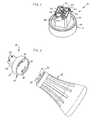
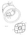
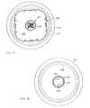
- FIG. 10is a bottom perspective view of a first example of a light fixture including a socket assembly in a cover assembly that is in the form of an interior door and having an integrated junction box.
- FIG. 11is a bottom plan view of the light fixture shown in FIG. 10 .
- FIG. 12is a side elevation view of the light fixture shown in FIG. 10 .
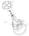
- FIG. 13is a perspective exploded view of the light fixture shown in FIG. 10 with the cover assembly removed.
- FIG. 14is a top perspective exploded view of the cover assembly in the form of an interior door and socket assembly of the light fixture shown in FIG. 10 .
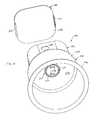
- FIG. 15is a bottom perspective exploded view of a second example of a light fixture including a socket assembly integrated into an interior wall and having a cover for an integrated junction box.
- FIG. 16is a top perspective exploded view of the light fixture shown in FIG. 15 .
- FIG. 17is a top plan view of the light fixture shown in FIG. 15 with the cover removed.
- FIG. 18is a bottom plan view of the light fixture shown in FIG. 15 .
- FIG. 19is a top perspective exploded view of the light fixture shown in FIG. 15 .
- FIG. 20is a top perspective view of a further example light fixture similar to that which is shown in FIG. 15 but without the socket assembly base integrally formed within an interior wall.
- FIG. 21is a top perspective view of an alternative example of a socket assembly within the light fixture shown in FIG. 15 and further including a Ground circuit.
- FIG. 22is a top perspective view of another example socket assembly, with the socket assembly including a plug-in connector to receive wires that are terminated in plugs.
- FIG. 23is a bottom perspective view the socket assembly and wires shown in FIG. 22 .
- FIG. 24is a side elevation view of the socket assembly and wires shown in FIG. 22 .
- FIG. 25is a top plan view of the socket assembly shown in FIG. 22 .
- FIG. 26is a bottom plan view of the socket assembly shown in FIG. 22 .
- FIG. 27is a top perspective exploded view of the socket assembly shown in FIG. 22 .
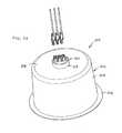
- FIG. 28is top perspective view of an example of a light fixture including the socket assembly shown in FIGS. 22-27 .
- FIG. 29is a top perspective view of an alternative example of a light fixture including an integrated version of the socket assembly shown in FIG. 22 .
- FIG. 30is a bottom perspective view of the light fixture shown in FIG. 29 .
- FIG. 31is a side elevation view of the light fixture shown in FIG. 29 .
- FIG. 32is a top perspective exploded view of the light fixture shown in FIG. 29 .
- FIG. 33is a top plan view of the light fixture shown in FIG. 29 .
- FIG. 34is a bottom plan view of the light fixture shown in FIG. 29 .
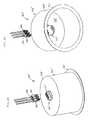
- FIG. 35is a bottom perspective view of an alternative example light fixture having the lamp housing and junction box integrally formed as a unit.
- FIG. 36is a side elevation view of the light fixture shown in FIG. 35 .
- FIG. 37is a top perspective view of a lighting system including a plurality of the light fixtures shown in FIG. 10 .
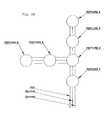
- FIG. 38is a schematic for the lighting system shown in FIG. 37 , and including a Ground circuit of the type provided in the light fixture shown in FIG. 21 .
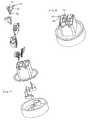
- FIGS. 1-7illustrate a socket assembly adapted for connection to an electrical apparatus, where the socket assembly includes multiple terminal assemblies with each terminal assembly having two or more metal components.
- the terminal assembliesare adapted for engagement by a lamp base and are adapted to receive push-in terminations.
- the example socket assembly 10has a base 12 with a side wall 14 and a bottom wall 16 .
- the bottom wall 16includes a pair of arcuate, key-hole shaped apertures 18 .
- Joined to the base 12is a connector housing 20 having a cover portion 22 and an upstanding side wall 24 .
- contacts 26Enclosed between the bottom wall 16 of the base 12 and the connector housing 20 are contacts 26 for connection to a lamp 25 having a lamp base 27 and conductors configured as posts or pins 29 of the lamp base.
- the apertures and contacts of the socket assembly that are provided to engage a lamp basecould be of an alternative configuration, such as a screw-in, four pin or other configuration, as desired to accommodate a selected lamp or bulb base.
- the socket assembly 10includes housing connector caps 30 having wire entry ports 32 for push-in wire termination to a power source, as well as to one or more additional socket assemblies (not shown).
- the housing connector caps 30are adapted to permit entry of Hot wires through one of the caps and Neutral wires through the other of the caps.
- the housing connector caps 30also include locking tabs 34 which engage mounting apertures 36 in the side wall of the connector housing 20 when the housing connector caps 30 are installed.
- Each terminal assembly 40includes a busbar 42 supported on a spring member 44 .
- the spring member 44includes a foot 46 joined to an upstanding leg 48 and individual depending spring fingers 50 .
- the foot 46includes apertures (not shown) for receiving rivets 52 formed from the busbar 42 to connect the busbar 42 to the foot 46 .
- Each depending spring finger 50is integrally connected to the upstanding leg 48 and has a free end 54 at its opposite end. As seen in FIGS. 6 and 7 the spring fingers 50 are bent out of the plane of the upstanding leg 48 .
- the free end 54may be further angled somewhat relative to the remainder of the spring finger 50 to provide an optimum angle for gripping a wire inserted under the spring finger 50 .
- the spring member 44is preferably formed of a resilient metal such as stainless steel.
- all but one of the spring fingers 50 of upstanding leg 48is opposite a wire entry port 32 so that a conductor of stripped end of a wire (not shown) may be inserted into a wire entry port 32 to encounter the spring finger 50 and move it upwardly as the conductor enters the connector housing 20 .
- the free end 54 of the spring finger 50will press on the conductor, preventing it from pulling out of the connector housing 20 and pushing it into firm engagement with the top face 56 of the busbar 42 .
- one of the spring fingers 50is not opposite a wire entry port 32 , and instead is opposite to and engages a blade 28 extending from a contact 26 .
- each terminal assembly 40is connected to a contact 26 within the socket assembly 10 and is configured for push-in termination of a conductor of one or more wires via one or more spring fingers 50 .
- each busbarmay incorporate a contact or other electrical engagement configuration to accommodate an alternative configuration of a lamp or bulb base.
- the busbar 42is a generally rectangular member made of tin-plated copper.
- the top face 56 of the busbar 42includes an entry edge 58 at a depression 60 and an exit edge 62 at a protrusion 64 .
- terms such as “top” and “bottom”are used herein for reference purposes only, as there is nothing inherent in the orientation of the busbar 42 that would make one side or the other of the busbar 42 a top, bottom, left or right portion.
- the entry edge 58will be considered the edge of the busbar 42 first crossed by a conductor entering the connector housing 20 and the exit edge 62 will be considered the edge of the busbar 42 potentially thereafter crossed by an entering conductor.
- the depression 60 and protrusion 64may be used to form a serpentine path for the conductor to traverse over the top face 56 of the busbar 42 .
- This configurationhelps the spring finger 50 retain the conductor in the connector housing 20 .
- the depression 60may surround the conductor at least partially on three sides, such as to prevent splaying of the conductive stripped end of a stranded wire.
- the busbar 42has a thickness and is connected to the foot 46 of the spring member 44 by rivets 52 that are formed by upsetting a portion of the busbar 42 or may be provided as separate fasteners. It will be understood that other methods for connecting the busbar 42 to the spring member 44 may be used, such as crimping, adhesives or the like. Alternatively, the busbar 42 may not be fixed to the spring at all. Rather, it could be otherwise supported by the connector housing 20 .
- the busbar 42may be replaced by a further example busbar 42 ′ that includes an integral contact 26 ′, which serves to replace the combination of the above-described busbar 42 and contact 26 .
- an alternative terminal assembly 40 ′is of somewhat similar construction in that it includes a foot 46 joined to an upstanding leg 48 and individual depending spring fingers 50 .
- the connection between the blade 28 of a contact 26 with a spring finger 50 and busbar 42 of the first exampleis effectively replaced by the busbar 42 ′ having an integral contact 26 ′ that is configured to receive a conductor of a lamp base.
- the remainder of the construction of the terminal assembly 40 ′is similar to that of the first example terminal assembly 40 , such as with respect to the materials and means of connection within the assembly.
- FIGS. 8 and 9provide an alternative example socket assembly that is similar to that of FIGS. 1-7 , but also includes wire port inserts 70 , each of which snaps into and is slidably received in one of the wire entry ports 32 .
- Each wire port insert 70includes a body 72 having a through port 74 and an extension 76 .
- the extension 76is configured to engage the rear surface of a spring finger 50 when depressed inwardly, so as to move the spring finger 50 further away from the top surface 56 of the busbar 42 , thus clearing the way for insertion of a conductor of a wire or relieving the grip on a previously inserted wire.
- use of the inserts 70provides a zero insertion force option for a respective conductor and permits the spring finger to be displaced to freely allow removal of the conductor, if desired.
- the wire entry ports 32 and busbar 42are arranged such that the busbar 42 is disposed at about a 17° angle to an entry axis of the wire ports 32 . That is, in this example, the busbar 42 with the depressions 60 is configured to be held at an angle of about 17° and somewhat interferes with the path of the inserted conductors to create a bump and/or angled surface for the conductor to pass over as the spring fingers of the spring member 44 press the conductors into the busbar top face 56 , further directing the conductors over the bump or angled surface provided by the protrusions 64 . This enhances both the holding force of the spring finger 50 and the electrical contact between the busbar 42 and the conductor.
- the socket assemblies of this disclosuremay be utilized in integrated light fixtures, with such fixtures being adapted to receive a lamp base and including a plurality of terminal assemblies.
- Each of the terminal assemblieshas two or more metal component, with each terminal assembly being adapted to receive push-in terminations.
- FIGS. 10-14an example of such a light fixture is illustrated in a light fixture 100 having a lamp housing 102 with a side wall 104 ending in an outward extending lip 106 for ease of installation along a surface of a ceiling (not shown).
- the lamp housing 102further includes a top wall 108 having an aperture 110 with a removable cover assembly 112 in the form of an interior door by which one can gain access to a junction box 114 , which may be formed in an integral manner.
- the lamp housing 102is shown in a relatively cylindrical shape, it may have alternative shapes or configurations and the cover assembly and junction box alternatively could be located along a side wall of the lamp housing.
- the junction box 114 in this exampleincludes side walls 116 having slots 118 , knock outs 120 (for receiving flexible or rigid conduit) and foldable flap closures 122 (for receiving and retaining in place flexible wiring such as Romex).
- the slots 118receive tabs 124 that extend from a body portion 126 of the cover assembly 112 .
- the cover assembly 112may have alternative shapes and sizes and may be connected to the lamp housing or junction box 114 via other methods and components, such as by hinging, latching or use of removable fasteners or the like.
- the junction boxmay have alternative shapes and configurations and may be located along a side wall of the lamp housing.
- a socket assembly 10mounted in the center of the body portion 126 of the removable cover assembly 112 .
- the light fixture 100may be formed of many different materials cost effectively, such as molded plastic or sheet metal, and that the junction box 114 may be joined to or integrated into the construction of the lamp housing 102 to form a single piece unit. This presents a cost effective assembly while providing full access to the wiring and socket assembly 10 via its connection or incorporation into the removable cover assembly 112 , even after installation of the light fixture 100 in a ceiling.
- a portion of the lamp housingmay be metalized or otherwise coated for heat dissipation and/or optical reflectance and/or a reflector, lens and trim ring may be added.
- a heat sinkmay be included within the light fixture and it will be understood that a ballast, driver or other electronic device may be mounted on the lamp housing or junction box, as desired.
- FIGS. 15-19illustrate a further example light fixture 200 having a lamp housing 202 with a side wall 204 ending in an outward extending lip 206 for ease of installation along a surface of a ceiling (not shown).
- the lamp housing 202further includes a top wall 208 having an integrally formed base 212 of a socket assembly 210 in a centrally located position.
- this example socket assembly 210is otherwise constructed in a manner similar to socket assembly 10 shown in FIGS. 1-7 , with correspondingly numbered components.
- alternative socket configurationscould be utilized to accommodate particularly selected lamps or bulbs having different base constructions and the terminal assembly and contacts may be integrated in alternative configurations that include at least two metal components.
- a removable cover 280is provided to gain access to an integral junction box 282 .
- the junction box 280includes side walls 284 having slots 286 , knock outs 288 (for receiving flexible or rigid conduit) and foldable flap closures 290 (for receiving and retaining in place flexible wiring such as Romex).
- the slots 286receive tabs 292 that extend from a body portion 294 of the cover 280 .
- the lamp housing and junction boxmay have other shapes and configurations.
- the cover 280may have alternative shapes and sizes and may be connected to the lamp housing or junction box via other methods and components, such as by hinging, latching or use of removable fasteners or the like.
- the socket assembly 200integrated into the center of the top wall 208 is the socket assembly 200 , and the removable cover 280 is connected at the top end of the junction box 282 .
- the socket assembly 210includes an upper connector housing 220 that is accessible by removal of the cover 280 , which is best appreciated in FIG. 17 .
- the light fixture 200may be formed of many different materials cost effectively, such as molded plastic or sheet metal, and that the junction box 282 may be joined to or integrated into the construction of the top of the lamp housing 202 to form a single unit. This presents an alternative cost effective assembly while providing full access to the wiring and socket assembly 210 via its connection to or incorporation into the top wall 208 of the lamp housing 220 and the removable cover 280 .
- FIG. 20illustrates an alternative light fixture 200 ′ which is similar in all respects to the above-discussed light fixture 200 , except that the base 212 ′ of the socket assembly 210 ′ is not integrally formed with the top wall 208 ′ of the lamp housing 220 ′. Instead, the top wall 208 ′ includes an aperture 296 ′ into which the base 212 ′ of the socket assembly 210 ′ is mounted, such as by snap fit, adhesive or other suitable joining methods.
- the socket assembly 210 ′is more like socket assembly 10 that is described above in detail.
- FIG. 21illustrates a closer view of a light fixture 200 ′′ which is similar to the light fixture 200 described above with respect to FIGS. 15-19 , but includes a modified version of the socket assembly 210 ′′ having an additional Ground wire circuit.
- the Ground wire circuitis provided via inclusion of a further connector housing 220 ′′ adjacent the previously described connector housing 220 .
- the additional connector housing 220 ′′includes a housing wall 224 , housing connector cap 230 ′′ having Ground wire entry ports 232 ′′.
- the connector housing 220 ′′provides one additional wire entry port 232 ′′ for connection of the socket assembly 220 ′′ to a grounding source.
- FIGS. 22-27illustrate an alternative example of a socket assembly 310 having a base 312 with a side wall 314 and a bottom wall 316 .
- the bottom wall 316includes a pair of arcuate, key-hole shaped apertures 318 .
- Joined to the base 312is a connector housing 320 having a cover portion 322 and separate upstanding side walls 324 .
- contacts 326Enclosed between the bottom wall 316 of the base 312 and the connector housing 320 are contacts 326 for connection to posts or pins of lamp base, such as posts 29 of the bulb 25 in FIG. 2A , although as noted above, alternative constructions that would be suitable to accommodate different lamp or bulb bases may be utilized.
- the contacts 326include a body 328 , lamp base engaging portions 330 and plug engaging blades 332 .
- the body 328 of the contacts 326are held in position relative to the apertures 318 by upstanding slotted members 334 that are formed on the bottom wall 316 .
- the slots 336receive and locate a portion of the body 328 of the contacts 326 to hold them in position for engagement with a lamp (not shown) and to locate the respective engaging blades 332 within the respective upstanding side walls 324 .
- the socket assembly 310is configured to receive wire ends that are terminated in plugs 340 .
- the plugs 340are structured for mating engagement with the upstanding side walls 324 of the connector housing 320 , and each plug includes a contact (not shown) that is joined to a conductor of a wire, such as by crimping or other suitable connection methods.
- This constructionincludes fewer components than the construction of socket assembly 10 , but does not permit push-in wire connections.
- FIG. 28shows a light fixture 300 having a lamp housing 302 with a side wall 304 ending in an outward extending lip 306 for ease of installation along a surface of a ceiling (not shown).
- the lamp housing 302further includes a top wall 308 having an aperture 314 that receives a socket assembly 310 as described above, and with connection by snap fit or other suitable means.
- Thisprovides a highly simplified light fixture construction by completely eliminating the junction box, and may be suitable in particular circumstances, such as DC power and/or low voltage installations.
- FIGS. 29-34illustrate an alternative example of a light fixture 300 ′ to that shown in FIG. 28 .
- the light fixture 310 ′includes a lamp housing 302 ′ with a side wall 304 ′ ending in an outward extending lip 306 ′ for ease of installation along a surface of a ceiling (not shown).
- the lamp housing 302 ′further includes a top wall 308 ′ having an integrally formed base 312 ′ of a socket assembly 310 ′.
- the socket assembly 310 ′includes an integral base 312 ′ with a side wall 314 ′ and a bottom wall 316 ′ with upstanding slotted members 334 ′.
- the bottom wall 316 ′includes a pair of arcuate, key-hole shaped apertures 318 ′.
- the socket assembly 310 ′is otherwise similar to the structure disclosed above with respect to the socket 310 of FIGS. 22-27 , with correspondingly numbered components.
- a cover portion 322 of a connector housingwhich has separate upstanding side walls 324 , and enclosed within the base 312 ′ are contacts 326 for engaging wire plug terminations to be electrically connected to posts or pins of lamp base.
- the contacts 326include a body 328 , lamp base engaging portions 330 and plug engaging blades 332 .
- FIGS. 35 and 36illustrate a further example lamp housing 202 ′′′ with an integral junction box 280 ′′′ that are formed together in plastic as a single unit, such as by molding, to arrive at a light fixture 200 ′′′ that is comparable in all other respects to that of the light fixture 200 ′ described above with reference to FIG. 20 .
- This constructionmay offer simplified manufacturing and assembly in a non-conductive material.
- a lighting systemcan be formed with a plurality of light fixtures that each include a socket assembly adapted to receive a lamp base and multiple terminal assemblies, where each terminal assembly has two or more metal components and the terminal assemblies of one of the plurality of light fixtures are adapted for connection to the terminal assemblies of another one of the plurality of light fixtures.
- the lighting system 500includes a plurality of light fixtures 100 having socket assemblies 10 , which are not shown in this figure but which were previously described with respect to FIGS. 1-7 .
- a plurality of light fixtures 100is connected to one another by daisy chaining, such as by use of wires (not shown) in conduit.
- a lighting system 500may be installed within a ceiling with minimal complexity and without requiring use of remote junction boxes for each light fixture.
- FIG. 38illustrates a schematic for the lighting system 500 , but also includes provision for use of a Hot wire, Neutral wire and Ground wire, as discussed with respect to the example shown in FIG. 21 .
- the light fixtures shown schematically in FIG. 38represent any of the preceding example light fixtures and socket assemblies.
- socket assemblies and electrical apparatussuch as for example, in light fixtures
- a plurality of electrical apparatusmay be combined into a system in many denominations and configurations, as desired.
- this disclosureis not intended to be limiting with respect to the particular choice of materials, dimensions or other aspects of the structures and components referred to herein. It will be appreciated that any variety of suitable materials of construction, configurations, shapes and sizes for the components and methods of connecting the components may be utilized to meet the particular needs and requirements of an end user.
- various modificationscan be made in the design and construction of such socket assemblies, electrical apparatus and systems without departing from the scope of the attached claims, and that the claims are not limited to the preferred embodiments illustrated.
Landscapes
- Arrangement Of Elements, Cooling, Sealing, Or The Like Of Lighting Devices (AREA)
- Non-Portable Lighting Devices Or Systems Thereof (AREA)
Abstract
Description
Claims (16)
Priority Applications (1)
| Application Number | Priority Date | Filing Date | Title |
|---|---|---|---|
| US12/983,660US8657474B2 (en) | 2010-01-05 | 2011-01-03 | Electrical socket, apparatus and system |
Applications Claiming Priority (2)
| Application Number | Priority Date | Filing Date | Title |
|---|---|---|---|
| US29228910P | 2010-01-05 | 2010-01-05 | |
| US12/983,660US8657474B2 (en) | 2010-01-05 | 2011-01-03 | Electrical socket, apparatus and system |
Publications (2)
| Publication Number | Publication Date |
|---|---|
| US20110164424A1 US20110164424A1 (en) | 2011-07-07 |
| US8657474B2true US8657474B2 (en) | 2014-02-25 |
Family
ID=44224605
Family Applications (1)
| Application Number | Title | Priority Date | Filing Date |
|---|---|---|---|
| US12/983,660Active2032-04-22US8657474B2 (en) | 2010-01-05 | 2011-01-03 | Electrical socket, apparatus and system |
Country Status (1)
| Country | Link |
|---|---|
| US (1) | US8657474B2 (en) |
Cited By (4)
| Publication number | Priority date | Publication date | Assignee | Title |
|---|---|---|---|---|
| US20110222291A1 (en)* | 2010-03-15 | 2011-09-15 | Chunghang Peng | Lighting fixture with integrated junction-box |
| US20150036359A1 (en)* | 2013-07-31 | 2015-02-05 | Livingstyle Enterprises Limited | Lighting device and lighting device assembling and disassembling method complying with safety regulations |
| US10935218B2 (en)* | 2017-10-30 | 2021-03-02 | Opple Lighting Co., Ltd. | Installation assembly of ceiling lighting fixture, ceiling lighting fixture and ceiling lamp |
| US20210160967A1 (en)* | 2019-11-22 | 2021-05-27 | JK Lighting Co., Ltd | Electric heating apparatus with multiple heating lamps |
Families Citing this family (8)
| Publication number | Priority date | Publication date | Assignee | Title |
|---|---|---|---|---|
| KR101095868B1 (en)* | 2011-09-08 | 2011-12-21 | 이슬기 | LED Lighting Module |
| US8807793B2 (en) | 2011-09-26 | 2014-08-19 | IDEAL, Industries, Inc. | Device for securing a source of LED light to a heat sink surface |
| US9605910B2 (en) | 2012-03-09 | 2017-03-28 | Ideal Industries, Inc. | Heat sink for use with a light source holding component |
| USD743914S1 (en)* | 2014-03-13 | 2015-11-24 | Cree, Inc. | Photocontrol receptacle for lighting fixture |
| USD843642S1 (en) | 2015-05-03 | 2019-03-19 | Lucifer Lighting Company | Cylindrical fixture mount |
| US20160319988A1 (en)* | 2015-05-03 | 2016-11-03 | Lucifer Lighting Company | Apparatuses Including Fixtures and/or Fixture Mounts and Related Methods |
| CN112490701B (en)* | 2020-12-23 | 2024-05-14 | 核工业理化工程研究院 | Combined power strip |
| US12129998B1 (en) | 2023-07-24 | 2024-10-29 | Wangs Alliance Corporation | Connectable lamp |
Citations (63)
| Publication number | Priority date | Publication date | Assignee | Title |
|---|---|---|---|---|
| US3093433A (en) | 1960-12-27 | 1963-06-11 | Underwriters Safety Device Co | Wire terminals and lead connector devices |
| US3351884A (en) | 1963-10-01 | 1967-11-07 | Gen Electric | Lampholders for electric discharge lamps |
| US3488626A (en) | 1968-01-29 | 1970-01-06 | J W Speaker Corp | Socket for small light bulbs |
| US3935445A (en) | 1974-03-04 | 1976-01-27 | Drag Specialties, Inc. | Socket mounting structure for vehicle lights |
| US4040709A (en) | 1975-11-12 | 1977-08-09 | Amp Incorporated | Lighting unit assembly |
| US4133595A (en) | 1978-03-06 | 1979-01-09 | Amp Incorporated | Double ended receptacle |
| US4704664A (en) | 1983-03-25 | 1987-11-03 | Scientific Component System, Inc. | Lamp apparatus |
| US4764128A (en) | 1986-10-20 | 1988-08-16 | Sam Cheng | Distribution hanger for decorative light string |
| US4922393A (en) | 1983-03-25 | 1990-05-01 | Scientific Component Systems, Inc. | Lamp apparatus |
| US4962447A (en) | 1989-09-05 | 1990-10-09 | Allan Ullman | Radio frequency signal and power distribution duct |
| US4971567A (en) | 1988-12-09 | 1990-11-20 | Japan Aviation Electronics Industry | Modular jack |
| US5057979A (en) | 1989-12-12 | 1991-10-15 | Thomas Industries, Inc. | Recessed lighting fixture |
| US5494456A (en) | 1994-10-03 | 1996-02-27 | Methode Electronics, Inc. | Wire-trap connector with anti-overstress member |
| US5662414A (en) | 1996-05-03 | 1997-09-02 | Nsi Enterprises, Inc. | Thermoplastic pan assembly for mounting recessed lighting fixtures in ceilings and the like |
| US5738436A (en) | 1996-09-17 | 1998-04-14 | M.G. Products, Inc. | Modular lighting fixture |
| US5746507A (en) | 1997-01-06 | 1998-05-05 | Thomas Industries, Inc. | Recessed lighting fixture for two light sizes |
| US5927843A (en) | 1997-07-24 | 1999-07-27 | Ruud Lighting, Inc. | Canopy light and related method |
| US5997158A (en) | 1998-02-20 | 1999-12-07 | Lsi Industries, Inc. | Retrofit canopy luminaire and method of installing same |
| US6030102A (en) | 1998-12-23 | 2000-02-29 | Cooper Technologies Company | Trim retention system for recessed lighting fixture |
| US6039597A (en) | 1996-07-26 | 2000-03-21 | Leviton Manufacturing Co., Inc. | Lampholder for compact fluorescent lamps |
| US6059422A (en) | 1995-09-22 | 2000-05-09 | Lsi Industries Inc. | Canopy luminaire |
| US6082878A (en) | 1998-02-03 | 2000-07-04 | Cooper Industries, Inc. | Fully rotatable recessed light fixture with movable stop and adjustable length bar hanger |
| US6116749A (en) | 1998-06-03 | 2000-09-12 | Spaulding Lighting, Inc. | Canopy luminaire assembly |
| US6123438A (en)* | 1998-08-24 | 2000-09-26 | Nsi Enterprises, Inc. | Insulation shield for recessed downlighting fixtures |
| US6149280A (en) | 1999-02-05 | 2000-11-21 | Spaulding Lighting, Inc. | Method and apparatus for retrofitting canopy luminaire assemblies |
| US6168299B1 (en) | 1999-04-30 | 2001-01-02 | Ellis Yan | Energy efficient recessed lighting fixture |
| US6290522B1 (en) | 1998-02-19 | 2001-09-18 | Leviton Manufacturing Co., Inc. | Fluorescent lampholder |
| US6299327B1 (en) | 1998-10-14 | 2001-10-09 | Itc, Inc. | Light fixture with multi-purpose mounting arrangement |
| US6570306B2 (en) | 1999-12-16 | 2003-05-27 | Bjb Gmbh & Co. Kg | Lamp-socket contact |
| US6588922B1 (en) | 1997-09-29 | 2003-07-08 | Juno Lighting, Inc. | Recessed lighting fixture with a columnar open mounting frame |
| US6682364B2 (en) | 2001-05-15 | 2004-01-27 | Entrelec S.A. | Connection device with pusher |
| US20040145899A1 (en)* | 2003-01-28 | 2004-07-29 | Riebling Michael L. | In-grade light fixture with hydraulic isolation |
| US20040232775A1 (en) | 2003-05-19 | 2004-11-25 | Nilssen Ole K. | Lighting system comprised of a unique direct current power supply and a plurality of gas discharge luminaires |
| USD500736S1 (en) | 2002-07-09 | 2005-01-11 | Matsushita Electric Works, Ltd. | Fluorescent light socket |
| US6964504B2 (en) | 2003-04-01 | 2005-11-15 | Hubbell Incorporated | Lighting system for direct wiring electric luminaires |
| US6972570B2 (en) | 2004-02-11 | 2005-12-06 | Schriefer Jay R | Quick-connect ballast testing and monitoring method and apparatus |
| US7168825B2 (en) | 2005-04-07 | 2007-01-30 | Mcarthur Robert M | Recessed light fixture |
| US7192315B2 (en) | 2001-10-04 | 2007-03-20 | Guide Corporation | Terminals for bulb sockets |
| US7249867B2 (en)* | 2005-06-10 | 2007-07-31 | Coarsegold Consulting, Inc. | Sealed lighting fixture having mechanisms for venting and equalizing interior air pressure |
| US7394019B2 (en) | 2004-09-28 | 2008-07-01 | Rick Gesue | Compact flush-mount self-contained receptacle (SCR) |
| US20080165538A1 (en) | 2003-03-31 | 2008-07-10 | Michael Callahan | Lighting systems and components thereof |
| US7399105B2 (en) | 2001-05-25 | 2008-07-15 | Lumination Llc | Illuminated signage employing light emitting diodes |
| US20080227318A1 (en) | 2003-12-23 | 2008-09-18 | Bsh Bosch Und Siemens Hausgerate Gmbh | Connector Device for Producing an Electrical Connection Between a Mains Cable and a Loom |
| US7436675B2 (en) | 2004-03-12 | 2008-10-14 | Juno Manufacturing, Inc. | Constant current class 3 lighting system |
| US7465174B1 (en) | 2007-10-16 | 2008-12-16 | International Business Machines Corporation | Coupling for connecting and disconnecting a plug and a socket |
| US7467888B2 (en) | 2004-12-31 | 2008-12-23 | Ole K. Nilssen | Quick change power supply |
| US20090017660A1 (en) | 2007-07-11 | 2009-01-15 | Braganza Austin R | Water Resistant Push-In Connector |
| US20090029596A1 (en) | 2005-10-26 | 2009-01-29 | Federal-Mogul Ignition Company | Molded electrical socket |
| US20090039799A1 (en)* | 2007-08-08 | 2009-02-12 | Newman Jr Robert C | Ballasted lamp socket for a compact fluorescent lamp |
| US20090053925A1 (en) | 2003-09-10 | 2009-02-26 | Pyrros Chrestos T | Modular Electrical Receptacle |
| US7524078B1 (en)* | 2008-01-18 | 2009-04-28 | Genlyte Thomas Group Llc | In-grade lighting fixture |
| US7530705B2 (en) | 2005-07-22 | 2009-05-12 | Genlyte Thomas Group Llc | Rotatable lamp with braking mechanism |
| US20090120683A1 (en) | 2005-11-30 | 2009-05-14 | Jim Hybiske | Cable organizer |
| US20090130879A1 (en) | 2007-08-09 | 2009-05-21 | Ross Johnson | Modular electrical distribution system for a building |
| US20090141499A1 (en) | 2006-12-15 | 2009-06-04 | Philips Koninklijke Electronics N.V. | Sensor module connector |
| US20090147507A1 (en) | 2005-10-03 | 2009-06-11 | Orion Energy Systems, Inc. | Modular light fixture with power pack |
| US20090181565A1 (en) | 2005-05-24 | 2009-07-16 | Boston Metal Products Corporation | System and method for distribution of electrical power |
| US20090186517A1 (en) | 2007-06-14 | 2009-07-23 | Ideal Industries, Inc. | Push-in wire connector with improved busbar |
| US7575338B1 (en) | 2005-10-03 | 2009-08-18 | Orion Energy Systems, Inc. | Modular light fixture with power pack |
| US20090227132A1 (en) | 2005-06-21 | 2009-09-10 | Ideal Industries, Inc. | Electrical Disconnect with Push-In Connectors |
| US20090231862A1 (en)* | 2008-03-17 | 2009-09-17 | Blix Lighting | Adjustable recessed light fixture |
| US20100014282A1 (en)* | 2008-07-15 | 2010-01-21 | Michael Danesh | Fire-resistant and noise attenuating recessed lighting assembly |
| US7806550B2 (en)* | 2007-11-27 | 2010-10-05 | Abl Ip Holding Llc | In-grade lighting system |
- 2011
- 2011-01-03USUS12/983,660patent/US8657474B2/enactiveActive
Patent Citations (67)
| Publication number | Priority date | Publication date | Assignee | Title |
|---|---|---|---|---|
| US3093433A (en) | 1960-12-27 | 1963-06-11 | Underwriters Safety Device Co | Wire terminals and lead connector devices |
| US3351884A (en) | 1963-10-01 | 1967-11-07 | Gen Electric | Lampholders for electric discharge lamps |
| US3488626A (en) | 1968-01-29 | 1970-01-06 | J W Speaker Corp | Socket for small light bulbs |
| US3935445A (en) | 1974-03-04 | 1976-01-27 | Drag Specialties, Inc. | Socket mounting structure for vehicle lights |
| US4040709A (en) | 1975-11-12 | 1977-08-09 | Amp Incorporated | Lighting unit assembly |
| US4133595A (en) | 1978-03-06 | 1979-01-09 | Amp Incorporated | Double ended receptacle |
| US4922393A (en) | 1983-03-25 | 1990-05-01 | Scientific Component Systems, Inc. | Lamp apparatus |
| US4704664A (en) | 1983-03-25 | 1987-11-03 | Scientific Component System, Inc. | Lamp apparatus |
| US4764128A (en) | 1986-10-20 | 1988-08-16 | Sam Cheng | Distribution hanger for decorative light string |
| US4971567A (en) | 1988-12-09 | 1990-11-20 | Japan Aviation Electronics Industry | Modular jack |
| US4962447A (en) | 1989-09-05 | 1990-10-09 | Allan Ullman | Radio frequency signal and power distribution duct |
| US5057979A (en) | 1989-12-12 | 1991-10-15 | Thomas Industries, Inc. | Recessed lighting fixture |
| US5494456A (en) | 1994-10-03 | 1996-02-27 | Methode Electronics, Inc. | Wire-trap connector with anti-overstress member |
| US6059422A (en) | 1995-09-22 | 2000-05-09 | Lsi Industries Inc. | Canopy luminaire |
| US5662414A (en) | 1996-05-03 | 1997-09-02 | Nsi Enterprises, Inc. | Thermoplastic pan assembly for mounting recessed lighting fixtures in ceilings and the like |
| US6039597A (en) | 1996-07-26 | 2000-03-21 | Leviton Manufacturing Co., Inc. | Lampholder for compact fluorescent lamps |
| US5738436A (en) | 1996-09-17 | 1998-04-14 | M.G. Products, Inc. | Modular lighting fixture |
| US6375338B1 (en) | 1996-09-17 | 2002-04-23 | Power & Light, Llc | Modular lighting fixture |
| US5746507A (en) | 1997-01-06 | 1998-05-05 | Thomas Industries, Inc. | Recessed lighting fixture for two light sizes |
| US5927843A (en) | 1997-07-24 | 1999-07-27 | Ruud Lighting, Inc. | Canopy light and related method |
| US6588922B1 (en) | 1997-09-29 | 2003-07-08 | Juno Lighting, Inc. | Recessed lighting fixture with a columnar open mounting frame |
| US6082878A (en) | 1998-02-03 | 2000-07-04 | Cooper Industries, Inc. | Fully rotatable recessed light fixture with movable stop and adjustable length bar hanger |
| US6290522B1 (en) | 1998-02-19 | 2001-09-18 | Leviton Manufacturing Co., Inc. | Fluorescent lampholder |
| US5997158A (en) | 1998-02-20 | 1999-12-07 | Lsi Industries, Inc. | Retrofit canopy luminaire and method of installing same |
| US6116749A (en) | 1998-06-03 | 2000-09-12 | Spaulding Lighting, Inc. | Canopy luminaire assembly |
| US6264344B1 (en) | 1998-06-03 | 2001-07-24 | Spaulding Lighting, Inc. | Canopy luminaire assembly |
| US6367945B2 (en) | 1998-06-03 | 2002-04-09 | Spalding Lighting, Inc. | Canopy luminaire assembly |
| US6123438A (en)* | 1998-08-24 | 2000-09-26 | Nsi Enterprises, Inc. | Insulation shield for recessed downlighting fixtures |
| US6299327B1 (en) | 1998-10-14 | 2001-10-09 | Itc, Inc. | Light fixture with multi-purpose mounting arrangement |
| US6030102A (en) | 1998-12-23 | 2000-02-29 | Cooper Technologies Company | Trim retention system for recessed lighting fixture |
| US6149280A (en) | 1999-02-05 | 2000-11-21 | Spaulding Lighting, Inc. | Method and apparatus for retrofitting canopy luminaire assemblies |
| US6168299B1 (en) | 1999-04-30 | 2001-01-02 | Ellis Yan | Energy efficient recessed lighting fixture |
| US6570306B2 (en) | 1999-12-16 | 2003-05-27 | Bjb Gmbh & Co. Kg | Lamp-socket contact |
| US6682364B2 (en) | 2001-05-15 | 2004-01-27 | Entrelec S.A. | Connection device with pusher |
| US7399105B2 (en) | 2001-05-25 | 2008-07-15 | Lumination Llc | Illuminated signage employing light emitting diodes |
| US7192315B2 (en) | 2001-10-04 | 2007-03-20 | Guide Corporation | Terminals for bulb sockets |
| USD500736S1 (en) | 2002-07-09 | 2005-01-11 | Matsushita Electric Works, Ltd. | Fluorescent light socket |
| US20040145899A1 (en)* | 2003-01-28 | 2004-07-29 | Riebling Michael L. | In-grade light fixture with hydraulic isolation |
| US20080165538A1 (en) | 2003-03-31 | 2008-07-10 | Michael Callahan | Lighting systems and components thereof |
| US6964504B2 (en) | 2003-04-01 | 2005-11-15 | Hubbell Incorporated | Lighting system for direct wiring electric luminaires |
| US20040232775A1 (en) | 2003-05-19 | 2004-11-25 | Nilssen Ole K. | Lighting system comprised of a unique direct current power supply and a plurality of gas discharge luminaires |
| US20090053925A1 (en) | 2003-09-10 | 2009-02-26 | Pyrros Chrestos T | Modular Electrical Receptacle |
| US20080227318A1 (en) | 2003-12-23 | 2008-09-18 | Bsh Bosch Und Siemens Hausgerate Gmbh | Connector Device for Producing an Electrical Connection Between a Mains Cable and a Loom |
| US6972570B2 (en) | 2004-02-11 | 2005-12-06 | Schriefer Jay R | Quick-connect ballast testing and monitoring method and apparatus |
| US7436675B2 (en) | 2004-03-12 | 2008-10-14 | Juno Manufacturing, Inc. | Constant current class 3 lighting system |
| US7394019B2 (en) | 2004-09-28 | 2008-07-01 | Rick Gesue | Compact flush-mount self-contained receptacle (SCR) |
| US7467888B2 (en) | 2004-12-31 | 2008-12-23 | Ole K. Nilssen | Quick change power supply |
| US7168825B2 (en) | 2005-04-07 | 2007-01-30 | Mcarthur Robert M | Recessed light fixture |
| US20090181565A1 (en) | 2005-05-24 | 2009-07-16 | Boston Metal Products Corporation | System and method for distribution of electrical power |
| US7249867B2 (en)* | 2005-06-10 | 2007-07-31 | Coarsegold Consulting, Inc. | Sealed lighting fixture having mechanisms for venting and equalizing interior air pressure |
| US20090227132A1 (en) | 2005-06-21 | 2009-09-10 | Ideal Industries, Inc. | Electrical Disconnect with Push-In Connectors |
| US7530705B2 (en) | 2005-07-22 | 2009-05-12 | Genlyte Thomas Group Llc | Rotatable lamp with braking mechanism |
| US7575338B1 (en) | 2005-10-03 | 2009-08-18 | Orion Energy Systems, Inc. | Modular light fixture with power pack |
| US20090147507A1 (en) | 2005-10-03 | 2009-06-11 | Orion Energy Systems, Inc. | Modular light fixture with power pack |
| US20090029596A1 (en) | 2005-10-26 | 2009-01-29 | Federal-Mogul Ignition Company | Molded electrical socket |
| US20090120683A1 (en) | 2005-11-30 | 2009-05-14 | Jim Hybiske | Cable organizer |
| US20090141499A1 (en) | 2006-12-15 | 2009-06-04 | Philips Koninklijke Electronics N.V. | Sensor module connector |
| US20090186517A1 (en) | 2007-06-14 | 2009-07-23 | Ideal Industries, Inc. | Push-in wire connector with improved busbar |
| US20090017660A1 (en) | 2007-07-11 | 2009-01-15 | Braganza Austin R | Water Resistant Push-In Connector |
| US20090039799A1 (en)* | 2007-08-08 | 2009-02-12 | Newman Jr Robert C | Ballasted lamp socket for a compact fluorescent lamp |
| US20090130879A1 (en) | 2007-08-09 | 2009-05-21 | Ross Johnson | Modular electrical distribution system for a building |
| US7465174B1 (en) | 2007-10-16 | 2008-12-16 | International Business Machines Corporation | Coupling for connecting and disconnecting a plug and a socket |
| US7806550B2 (en)* | 2007-11-27 | 2010-10-05 | Abl Ip Holding Llc | In-grade lighting system |
| US7524078B1 (en)* | 2008-01-18 | 2009-04-28 | Genlyte Thomas Group Llc | In-grade lighting fixture |
| US20090185378A1 (en)* | 2008-01-18 | 2009-07-23 | Matthew Pressel | In-grade lighting fixture |
| US20090231862A1 (en)* | 2008-03-17 | 2009-09-17 | Blix Lighting | Adjustable recessed light fixture |
| US20100014282A1 (en)* | 2008-07-15 | 2010-01-21 | Michael Danesh | Fire-resistant and noise attenuating recessed lighting assembly |
Cited By (6)
| Publication number | Priority date | Publication date | Assignee | Title |
|---|---|---|---|---|
| US20110222291A1 (en)* | 2010-03-15 | 2011-09-15 | Chunghang Peng | Lighting fixture with integrated junction-box |
| US20150036359A1 (en)* | 2013-07-31 | 2015-02-05 | Livingstyle Enterprises Limited | Lighting device and lighting device assembling and disassembling method complying with safety regulations |
| US9951937B2 (en)* | 2013-07-31 | 2018-04-24 | Livingstyle Enterprises Limited | Lighting device and lighting device assembling and disassembling method complying with safety regulations |
| US10935218B2 (en)* | 2017-10-30 | 2021-03-02 | Opple Lighting Co., Ltd. | Installation assembly of ceiling lighting fixture, ceiling lighting fixture and ceiling lamp |
| US20210160967A1 (en)* | 2019-11-22 | 2021-05-27 | JK Lighting Co., Ltd | Electric heating apparatus with multiple heating lamps |
| US11653421B2 (en)* | 2019-11-22 | 2023-05-16 | JK Lighting Co., Ltd | Electric heating apparatus with multiple heating lamps |
Also Published As
| Publication number | Publication date |
|---|---|
| US20110164424A1 (en) | 2011-07-07 |
Similar Documents
| Publication | Publication Date | Title |
|---|---|---|
| US8657474B2 (en) | Electrical socket, apparatus and system | |
| US5702176A (en) | Modular connector device | |
| US8500498B2 (en) | Electrical wire and sheet-metal connector | |
| US8033711B2 (en) | Field bendable line voltage track lighting system | |
| US8062072B2 (en) | Tamper resistant convenience outlet | |
| US9366418B2 (en) | Method, apparatus and system for connecting a light emitting diode light fixture to a mains power conductor | |
| US7794283B2 (en) | Socket, plug, and adaptor combination with waterproof arrangement | |
| US7794132B2 (en) | Lighting system | |
| US8353716B2 (en) | Terminal structures for wiring devices | |
| US7468488B1 (en) | Connection mechanism for coupling a power module to an electrical busway | |
| US20040196651A1 (en) | Lighting system for direct wiring electric luminaires | |
| US8480420B2 (en) | Outlet and light assembly with internal wiring connection | |
| WO2007033241A2 (en) | Fluorescent lampholder | |
| US8662695B2 (en) | Modular electrical distribution system for a building | |
| US20100093206A1 (en) | Electrical connector for electrical communication between a power cable and an electrical device | |
| US9570863B2 (en) | Grounding apparatus for a safety grounded tree | |
| US9496659B2 (en) | Grounding apparatus for a safety grounded tree | |
| US20110053421A1 (en) | Electrical connector for terminating the end of an electrical cable | |
| US5556297A (en) | Snap-on extension wire socket with electrical conductor insulation piercer | |
| US4644453A (en) | Portable fluorescent light unit | |
| US20190067890A1 (en) | Electrical adapter with integral connector | |
| US20060044841A1 (en) | Combination lighting module and tool-less bus system utilizing the same | |
| CN1069788C (en) | power adapter | |
| US10364945B2 (en) | Electrical wall receptacle, LED module, and lamp system | |
| RU2587979C2 (en) | Set of electrical equipment for connection of radiant energy source (infrared radiation, visible radiation and ultraviolet radiation) compact electric energy-saving lamp to source of electric energy |
Legal Events
| Date | Code | Title | Description |
|---|---|---|---|
| STCF | Information on status: patent grant | Free format text:PATENTED CASE | |
| AS | Assignment | Owner name:IDEAL INDUSTRIES INC., ILLINOIS Free format text:ASSIGNMENT OF ASSIGNORS INTEREST;ASSIGNORS:BREEN, DENNIS M., IV;SWEDBERG, BENJAMIN D.;ZANTOUT, ALAN E.;REEL/FRAME:037654/0899 Effective date:20100121 | |
| MAFP | Maintenance fee payment | Free format text:PAYMENT OF MAINTENANCE FEE, 4TH YEAR, LARGE ENTITY (ORIGINAL EVENT CODE: M1551) Year of fee payment:4 | |
| MAFP | Maintenance fee payment | Free format text:PAYMENT OF MAINTENANCE FEE, 8TH YEAR, LARGE ENTITY (ORIGINAL EVENT CODE: M1552); ENTITY STATUS OF PATENT OWNER: LARGE ENTITY Year of fee payment:8 | |
| AS | Assignment | Owner name:JPMORGAN CHASE BANK, N.A., AS ADMINISTRATIVE AGENT, ILLINOIS Free format text:SECURITY INTEREST;ASSIGNORS:IDEAL INDUSTRIES, INC.;ANDERSON POWER PRODUCTS, INC.;REEL/FRAME:066358/0354 Effective date:20240119 | |
| MAFP | Maintenance fee payment | Free format text:PAYMENT OF MAINTENANCE FEE, 12TH YEAR, LARGE ENTITY (ORIGINAL EVENT CODE: M1553); ENTITY STATUS OF PATENT OWNER: LARGE ENTITY Year of fee payment:12 |