US8657172B2 - Device for dispensing plastic fasteners - Google Patents
Device for dispensing plastic fastenersDownload PDFInfo
- Publication number
- US8657172B2 US8657172B2US13/209,986US201113209986AUS8657172B2US 8657172 B2US8657172 B2US 8657172B2US 201113209986 AUS201113209986 AUS 201113209986AUS 8657172 B2US8657172 B2US 8657172B2
- Authority
- US
- United States
- Prior art keywords
- needle
- fastener
- pair
- supply
- needle block
- Prior art date
- Legal status (The legal status is an assumption and is not a legal conclusion. Google has not performed a legal analysis and makes no representation as to the accuracy of the status listed.)
- Active, expires
Links
Images


Classifications
- B—PERFORMING OPERATIONS; TRANSPORTING
- B65—CONVEYING; PACKING; STORING; HANDLING THIN OR FILAMENTARY MATERIAL
- B65C—LABELLING OR TAGGING MACHINES, APPARATUS, OR PROCESSES
- B65C7/00—Affixing tags
- B65C7/003—Affixing tags using paddle-shaped plastic pins
- B65C7/005—Portable tools
- B—PERFORMING OPERATIONS; TRANSPORTING
- B65—CONVEYING; PACKING; STORING; HANDLING THIN OR FILAMENTARY MATERIAL
- B65C—LABELLING OR TAGGING MACHINES, APPARATUS, OR PROCESSES
- B65C7/00—Affixing tags
- B—PERFORMING OPERATIONS; TRANSPORTING
- B65—CONVEYING; PACKING; STORING; HANDLING THIN OR FILAMENTARY MATERIAL
- B65C—LABELLING OR TAGGING MACHINES, APPARATUS, OR PROCESSES
- B65C7/00—Affixing tags
- B65C7/003—Affixing tags using paddle-shaped plastic pins
- B—PERFORMING OPERATIONS; TRANSPORTING
- B65—CONVEYING; PACKING; STORING; HANDLING THIN OR FILAMENTARY MATERIAL
- B65C—LABELLING OR TAGGING MACHINES, APPARATUS, OR PROCESSES
- B65C7/00—Affixing tags
- B65C7/003—Affixing tags using paddle-shaped plastic pins
- B65C7/005—Portable tools
- B65C7/006—Portable tools electrically actuated
- G—PHYSICS
- G09—EDUCATION; CRYPTOGRAPHY; DISPLAY; ADVERTISING; SEALS
- G09F—DISPLAYING; ADVERTISING; SIGNS; LABELS OR NAME-PLATES; SEALS
- G09F3/00—Labels, tag tickets, or similar identification or indication means; Seals; Postage or like stamps
- G09F3/08—Fastening or securing by means not forming part of the material of the label itself
- G09F3/12—Fastening or securing by means not forming part of the material of the label itself by pins, staples, or the like
Definitions
- the present inventionrelates generally to plastic fasteners and more particularly to devices used in the dispensing of plastic fasteners.
- Plastic fastenersalso commonly referred to in the art as plastic attachments
- plastic attachmentsare well known in the art and commonly used to couple articles of commerce to packaging, buttons to fabric, merchandising tags to articles of commerce, or, in general, any two desired articles.
- One type of plastic fastener which is widely used in commerceis manufactured in an H-shaped configuration, with two shortened parallel cross-bars, or T-bars, interconnected at their approximate midpoints by a thin, flexible filament that extends orthogonally therebetween.
- Plastic fasteners of the type described aboveare commonly fabricated as part of continuously connected ladder stock that is produced from one or more flexible plastic materials, such as nylon and polypropylene, using conventional molding or stamping techniques.
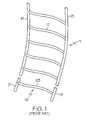
- FIG. 1there is shown a length of continuously connected ladder stock 11 that is well known in the art.
- Ladder, or fastener, stock 11is formed from two elongated and continuous plastic side members, or rails, 13 and 15 that are interconnected by a plurality of equidistantly spaced cross-links, or filaments, 17 . By severing each of side rails 13 and 15 at the approximate midpoint between successive filaments 17 , a plurality of individual plastic fasteners 18 can be produced from ladder stock 11 .
- Each plastic fastener 18 produced from ladder stock 11comprises a pair of cross-bars 19 and 21 that are interconnected by a thin, flexible filament 23 , with cross-bars 19 and 21 being derived from side rails 13 and 15 , respectively, and filament 23 being derived from a corresponding cross-link 17 .
- Ladder stock of the type described aboveis shown in U.S. Pat. No. 4,039,078 to A. R. Bone and U.S. Pat. No. 5,615,816 to C. L. Deschenes, the disclosures of both patents being incorporated herein by reference.
- Ladder stock of the type described aboveis presently manufactured and sold by Avery DennisonTM Corporation of Pasadena, Calif. under the Plastic Staple® and Elastic StapleTM lines of plastic fasteners.
- the commercialized ladder stockis traditionally wound onto a reel, or spool, which is sized and shaped to hold a supply of ladder stock that yields approximately 25,000 fasteners.
- One well known automated device for dispensing individual plastic fasteners from a reel of ladder-type fastener stockincludes a pair of hollow needles that are adapted to penetrate through one or more items, a feed mechanism for advancing each rail of the supply of ladder stock into axial alignment behind the longitudinal bore defined by a corresponding hollow needle, a severing mechanism for severing a fastener to be dispensed through the pair of hollowed needles from the remainder of the ladder stock, and an ejection mechanism for ejecting the cross-bars of the severed fastener through the bores of the pair of hollowed needles and, in turn, through the particular items that are penetrated by the needles.
- the devicefor dispensing plastic attachments from a roll of continuously connected ladder stock.
- the deviceincludes a pair of hollow slotted needles, each needle having a sharpened tip, a rear end and a longitudinal axis.
- a feed wheelplaced proximate to the rear ends of the pair of needles, is used to feed the side rails of the ladder stock into the pair of needles through their respective rear ends at angles relative to the longitudinal axes thereof.
- an attachmentis severed from the remainder of the ladder stock by a knife and is then expelled from the needles by a pair of ejector rods movable along the longitudinal axes of the pair of needles. Because attachments are fed into the pair of needles at angles relative to their longitudinal axes, no shuttling of the needles between an attachment feeding position and an attachment ejection position is required.
- the pair of needles, the feed wheel, the knife, and the pair of ejector rodsare all mounted on a vertically movable head member, or head.
- An induction motoris used to move the head member between an attachment dispensing position and a withdrawal position. The vertical movement of the head member drives the operation of the feed wheel, the knife and the ejector rods.
- fasteners of the type as described aboveare commonly used in a wide variety of different applications to secure together two or more items.
- fasteners of the type described aboveare commonly used in packaging applications to secure an article of commerce to a display card.
- the display cardis first positioned on an anvil for the fastener dispensing machine.
- the article of commerceis placed in its desired location on the top surface of the display card.
- the pair of needlespenetrates through the display card on opposite sides of the article of commerce and in close proximity relative thereto.
- each of the pair of cross-membersengages the underside of the card with the thin filament stretching tightly across the front of the article.
- the dispensed fastenerserves to secure the article to the display card in an inconspicuous and unobtrusive manner.
- adjusting the spacing between needlesis often required to accommodate supplies of ladder stock with cross-links of varying lengths (e.g., between 0.25 inches and 0.38 inches).
- adjusting the spacing between needlesis often required to account for variances in the size and shape of articles that are commonly joined using plastic fasteners (e.g., items of different widths that are secured to display cards).
- fastener dispensing deviceswith variable needle spacing are known in the art.
- FIG. 2there are shown selected components for a prior art device for dispensing individual plastic fasteners from a supply of ladder stock, the fastener dispensing device being identified generally by reference numeral 31 .
- device 31includes a pair of needles 33 - 1 and 33 - 2 that are individually coupled to a motor-driven shuttle 35 by corresponding, mirror image, needle block assemblies 37 - 1 and 37 - 2 , respectively.
- the lateral position of at least one needle block assembly 37is adjustable to enable the spacing between needles 33 to be modified as needed.
- needle block assemblies 37 - 1 and 37 - 2not only serve to retain needles 33 but also include guide channels 39 - 1 and 39 - 2 , respectively, that assist in positioning side rails 13 and 15 of ladder stock 11 that are fed into device 31 into proper alignment behind hollow needles 33 .
- fastener dispensing devices with variable needle spacing capabilitieshave been found to suffer from a notable drawback. Specifically, when needles 33 are drawn relatively close to one another, filaments 17 tend to distort (i.e., bow, twist and/or loop) in a random, irregular pattern, as shown in FIG. 2 .
- filaments 17tend to distort (i.e., bow, twist and/or loop) in a random, irregular pattern, as shown in FIG. 2 .
- the fastener dispensing device with closely spaced needlesis used in high speed dispensing applications, the presence of irregularly patterned filament distortions in the ladder stock has been found to significantly increase the likelihood of jamming. Once a jamming condition occurs, the fastener dispensing device needs to be shut down until a relatively labor-intensive and time-consuming repair can occur to remove the jammed ladder stock, which is highly undesirable.
- a device for dispensing an individual plastic fastener from a supply of fastener stockthe fastener stock being shaped to include a pair of continuous side rails to which are coupled a plurality of equidistantly spaced cross-links, the individual fastener comprising a pair of shortened cross-bars that are interconnected by at least one flexible filament
- the devicecomprising (a) a head assembly adapted to receive the supply of fastener stock, sever an individual fastener from the supply of fastener stock and eject the individual fastener during a single stroke of its actuation cycle, and (b) a motor for driving the head assembly through its actuation cycle, (c) wherein the head assembly is adapted to limit distortion of one or more cross-links for the supply of fastener stock fed thereinto within a single plane.
- FIG. 1depicts an enlarged, fragmentary, front perspective view of a length of continuously connected fastener stock that is well known in the art
- FIG. 2depicts a fragmentary, front perspective view of selected components of a prior art fastener dispensing device, the device being shown with a length of the fastener stock shown in FIG. 1 fed thereinto;
- FIG. 3depicts a top perspective view of a fastener dispensing device constructed according to the teachings of the present invention, the fastener dispensing device being shown with a reel of the fastener stock shown in FIG. 1 mounted thereon and fed thereinto;
- FIG. 4depicts a rear perspective view of the fastener dispensing device shown in FIG. 3 , the fastener dispensing device being shown with its housing and door removed therefrom for purposes of simplicity and clarity;
- FIG. 5depicts a fragmentary front perspective view of selected components of the head assembly for the fastener dispensing device and the reel of continuously connected fastener stock shown in FIG. 3 , the fastener stock being shown in dashed form;
- FIG. 6depicts a front perspective view of the pair of needle block assemblies shown in FIG. 5 ;
- FIG. 7depicts an exploded front perspective view of the left side needle block assembly shown in FIG. 6 ;
- FIG. 8depicts an exploded front perspective view of the right side needle block assembly shown in FIG. 6 .
- FIG. 3there is shown a perspective view of a device for dispensing individual plastic fasteners from a supply of continuously connected ladder stock, the device being constructed according to the teachings of the present invention and identified generally by reference numeral 111 .
- device 111is specifically designed to limit filament distortion in the upward direction (as represented by arrow U in FIG. 3 ) rather than in the frontward or rearward directions (as represented by arrows F and R, respectively, in FIG. 3 ) in order to improve operational reliability.
- device 111is described herein as being used to dispense individual fasteners 18 from prior art ladder stock 11 .
- device 111not limited to use with any particular type of ladder stock. Rather, it is to be understood that device 111 could be used to dispense individual fasteners from alternate types of dual-rail fastener stock without departing from the spirit of the present invention.
- device 111comprises a substantially rectangular base 113 which serves as the support, or foundation, for device 111 .
- Base 113may be provided with means to facilitate securing device 111 to a workstation or other similar platform, such as circular transverse bores 115 formed at selected locations along its periphery through which screws can be driven.
- a block-shaped neck 117is integrally formed onto the top surface of base 113 .
- An enlarged, rectangular frame 119is formed on top of neck 117 .
- frame 119serves as the support, or floor, on which various mechanical and electrical components for device 111 are mounted.
- An elongated support arm 121extends out from both base 113 and neck 117 in an upward and forward manner, support arm 121 being spaced substantially away from the underside of frame 119 .
- a reactor plate 123is mounted on the free end of support arm 121 and functions, among other things, to support the articles to be coupled by one or more fasteners 18 using device 111 .
- a protective housing 125extends upwardly from the free end of frame 119 and includes left and right side casings 127 - 1 and 127 - 2 that are secured together by screws. Housing 125 is preferably constructed of a rigid, durable and impact-resistant material, such as plastic, and serves to protect the majority of the electrical and mechanical components for device 111 that are mounted on frame 119 .
- An arcuate recess 129is formed in the top surface of housing 125 . Furthermore, a cylindrical reel holder 131 is mounted on right side casing 127 - 2 and extends transversely through recess 129 . Holder 131 is sized and shaped to axially pass through a longitudinal bore formed in a reel 133 of ladder stock 11 that is positioned within recess 129 . Accordingly, holder 131 serves to support reel 133 in such a manner that reel 133 is capable of freely rotating thereon, thereby affording device 111 with the capability to continuously dispense plastic fasteners 18 in an automated fashion. It should be noted that the majority of reel 133 is retained within recess 129 , thereby rendering the combination of reel 133 and device 111 relatively streamlined and compact in nature, which is highly desirable.
- a door 135encloses the front end of housing 125 and is pivotally connected to right side casing 127 - 2 by hinges to provide access to the head assembly for device 111 .
- a narrow slot 139is defined between door 135 and housing 125 through which a supply of ladder stock 11 may be fed.
- the dimensions of slot 139are minimally greater than the lateral cross-section of ladder stock 11 so as to limit the extent by which undesirable contaminants (e.g., dust) can enter into the interior cavity defined by housing 125 .
- a user interface 141is provided in the front of pivotally mounted door 135 and preferably includes a digital display panel 143 (e.g., an LCD screen) and one or more control buttons 145 - 1 thru 145 - 4 .
- user interface 141provides the operator with means to both monitor relevant historical data relating to usage of device 111 and regulate certain operational characteristics of device 111 , which is highly desirable.
- device 111includes a head assembly 147 mounted on frame 119 behind door 135 that is responsible for, among other things, feeding the supply of ladder stock 11 into device 111 , severing an individual fastener 18 from ladder stock 11 and, in turn, ejecting the severed fastener 18 through the desired articles.
- head assembly 147can be easily accessed by the operator by pivoting door 135 open.
- Head assembly 147comprises a vertically extending mount 149 that is fixedly retained in place on frame 119 , mount 149 being generally U-shaped in lateral cross-section.
- head assembly 147includes a motor-driven, vertically displaceable head 151 that is slidably coupled to mount 149 , the function of head 151 to become apparent below.
- head 151comprises a shuttle, or base, 153 that is slidably mounted on mount 149 and vertically driven by a motor 154 , a pair hollow needles 155 - 1 and 155 - 2 that are coupled to vertically displaceable shuttle 153 , a feed mechanism 157 for advancing the side rails 13 and 15 of ladder stock 11 into axial alignment behind the longitudinal bores defined by needles 155 , a severing mechanism 159 for cutting side members 13 and 15 of ladder stock 11 at the approximate midpoint between successive cross-links 17 to separate an individual plastic fastener 18 from the remainder of ladder stock 11 , and an ejection mechanism 161 for ejecting cross-bars 19 and 21 of a severed plastic fastener 18 through needles 155 - 1 and 155 - 2 and in turn through one or more of the items to be joined together by fastener 18 .
- Each needle 155is conventional in construction and includes an elongated longitudinal bore 163 and a narrow longitudinal slot 165 in communication with bore 163 .
- needles 155are coupled to motor-driven shuttle 153 . Accordingly, it is to be understood that the downward displacement of shuttle 153 in turn causes needles 155 to similarly travel downward so as to penetrate through any articles supported on reactor plate 123 that are to be coupled together by plastic fasteners 18 .
- Needles 155 - 1 and 155 - 2are coupled to motor-driven shuttle 153 by corresponding needle block assemblies 167 - 1 and 167 - 2 , respectively.
- needle block assemblies 167are responsible for both retaining needles 155 and assisting in the guidance of side rails 13 and 15 of ladder stock 11 that is fed into device 31 into position behind hollow needles 155 - 1 and 155 - 2 , respectively.
- needle block assemblies 167are additionally designed to apply pressure onto the lowermost cross-links 17 of fastener stock 11 that is fed into device 111 so as to limit filament distortion within a single plane (i.e., upward in the plane defined by arrow U in FIG. 5 ), as will be described in detail below below.
- left side needle block assembly 167 - 1comprises a needle block 169 - 1 that is fixedly mounted onto the underside of shuttle 153 , a guide block 171 - 1 mounted on the front of needle block 169 - 1 and a cover plate 173 - 1 mounted on the front of guide block 171 - 1 .
- needle block 169 - 1 , guide block 171 - 1 and cover plate 173 - 1define a substantially enclosed feed channel 175 - 1 that is designed to transition side rail 15 into axial alignment behind needle 155 - 1 .
- Needle block 169 - 1is a unitary, generally L-shaped support member that includes a substantially flat top surface 177 - 1 , a substantially flat bottom surface 179 - 1 , a front end surface 181 - 1 , a rear end surface 183 - 1 , an inner side surface 185 - 1 an outer side surface 187 - 1 .
- a pair of vertically oriented bores 189 - 1is formed in needle block 169 - 1 along rear end surface 183 - 1 .
- a pair of corresponding screwsis disposed through bores 189 and into threaded engagement with holes in the underside of shuttle 153 to secure needle block 169 - 1 onto shuttle 153 .
- Needle block 169 - 1is also shaped to define a partially protruding, vertical needle bore 191 - 1 in its bottom surface 179 - 1 along inner surface 185 - 1 , bore 191 - 1 being dimensioned to fittingly receive the base, or stem, of needle 155 - 1 .
- a transverse hole 193 - 1is formed in front end surface 181 - 1 that extends into communication with needle bore 191 - 1 .
- a retention screw 195 - 1can be axially driven through bore 191 - 1 and into frictional engagement with needle 155 - 1 mounted therein, thereby fixedly securing needle 155 - 1 in place within needle block 169 - 1 .
- withdrawal of retention screw 195 - 1 from bore 191 - 1thereby allows for the removal of needle 155 - 1 from needle block 169 - 1 (e.g., for replacement, repairs, etc.).
- a lower feed channel 197 - 1is formed in top surface 177 - 1 of needle block 169 - 1 in coaxial alignment with needle bore 191 - 1 .
- side rail 15 of ladder stock 11can be axially advanced through lower feed channel 197 - 1 and into alignment behind needle 155 - 1 , as will be described further below.
- a chamfered face 199 - 1is formed at the junction of top and inner side surfaces 177 - 1 and 185 - 1 , face 199 - 1 extending at an approximate 30 degree angle relative to the vertical axis to facilitate entry of side rail 15 from lower feed channel 197 - 1 into hollow needle 155 - 1 .
- Front end surface 181 - 1is shaped to include a recess 201 - 1 along outer side surface 187 - 1 , recess 201 - 1 being dimensioned to receive a portion of guide block 171 - 1 .
- a pair of spaced apart posts 203 - 1is formed along front end surface 181 - 1 and project into recess 201 - 1 .
- a threaded hole(not shown) is formed into front end surface 181 - 1 between posts 203 - 1 , the function of posts 203 - 1 and the threaded hole to become apparent below.
- Guide block 171 - 1is a unitary member that includes a substantially flat top surface 207 - 1 , a substantially flat bottom surface 209 - 1 , a front end surface 211 - 1 , a rear end surface 213 - 1 , an inner side surface 215 - 1 an outer side surface 217 - 1 .
- a pair of boresextends into rear end surface 213 - 1 and are aligned and dimensioned to fittingly receive posts 203 - 1 when guide block 171 - 1 is mounted on needle block 169 - 1 .
- a transverse bore 219 - 1extends through guide block that aligns with the threaded hole in needle block 169 - 1 when guide block 171 - 1 is mounted on needle block 169 - 1 .
- a threaded screw 221 - 1can be inserted through bore 219 - 1 and into engagement with the threaded hole in needle block 169 - 1 to retain guide block 171 - 1 in place on needle block 169 - 1 .
- Front end surface 211 - 1 of guide block 171 - 1is recessed along inner side surface 215 - 1 so as to define an angled front wall 223 - 1 .
- a pair of spaced apart pins 225 - 1extends out from angled front wall 223 - 1 .
- a threaded hole 227 - 1is formed into angled front wall 223 - 1 between pins 225 - 1 .
- pins 225 - 1 and hole 227 - 1assist in securing cover plate 173 - 1 to guide block 171 - 1 .
- a funnel-shaped cutout 229 - 1is formed into angled front wall 223 - 1 along inner side surface 215 - 1 , the inclusion of cutout 229 - 1 to become apparent below.
- cutout 229 - 1tapers gradually inward from top surface 207 - 1 to bottom surface 209 - 1 so as to axially align with the entrance for lower feed channel 197 - 1 .
- a wedged-shaped projection, or shelf, 231 - 1extends out from inner side surface 215 - 1 along its bottom edge. Shelf 231 - 1 includes a flat front contact surface 233 - 1 that is generally flush (i.e. coplanar) with cutout 229 - 1 . As will be described further below, shelf 231 - 1 is provided to prevent rearward distortion of the lowermost filaments 17 in ladder stock 11 that is fed into device 111 .
- An upwardly protruding ejector rod support block 235 - 1is formed onto top surface 207 - 1 along rear end surface 213 - 1 .
- the rear surface of support block 235 - 1is shaped to define a vertically extending, longitudinal channel 237 - 1 that is generally semi-circular in cross-section.
- an ejector rod for ejection mechanism 161is designed to displace vertically downward within channel 237 - 1 and push cross-bar 21 of severed fastener 18 out through the open tip of needle 155 - 1 .
- Cover plate 173 - 1is generally in the form of a rectangular plate that includes a flat front surface 239 - 1 and a flat rear surface 241 - 1 .
- Cover plate 173 - 1is shaped to define a pair of transverse bores 243 - 1 that are arranged and dimensioned to fittingly receive pins 225 - 1 on guide block 171 - 1 .
- a central bore 245 - 1is formed into cover plate 173 - 1 between bores 243 - 1 .
- a hex screw 247 - 1(with a washer 249 - 1 axially mounted thereon) can be inserted through central bore 245 - 1 and into threaded engagement with threaded hole 227 - 1 to retain cover plate 173 - 1 onto guide block 171 - 1 .
- upper feed channel 251 - 1 and lower feed channel 197 - 1together define the continuous feed channel 175 - 1 for needle block assembly 167 - 1 , with the flat front contact surface 233 - 1 of shelf 231 - 1 extending immediately inside and behind the continuous filament slot 253 - 1 for feed channel 175 - 1 , as seen most clearly in FIG. 6 .
- right needle block assembly 167 - 2is similar in construction to left needle block assembly 167 - 1 in that right needle block assembly 167 - 2 includes a needle block 169 - 2 fixedly mounted onto the underside of shuttle 153 , a guide block 171 - 2 mounted on the front of needle block 169 - 2 and a cover plate 173 - 2 mounted on the front of guide block 171 - 2 , with each of needle block 169 - 2 , guide block 171 - 2 and cover plate 173 - 2 being a rough mirror image of needle block 169 - 1 , guide block 171 - 1 and cover plate 173 - 1 , respectively. Accordingly, it is to be understood that shelf 231 - 2 on guide block 171 - 2 similarly applies continuous pressure against the rear of the lowermost cross-links 17 of fastener stock 11 fed into device 111 so as to prevent rearward distortion, which is highly desirable.
- right needle block 169 - 2is designed to be laterally displaced relative to left needle block 169 - 1 and, in turn, secured to shuttle 153 by passing threaded screws through vertical bores 189 - 2 .
- the spacing between needles 155 - 1 and 155 - 2can be adjusted, preferably between 6.5 mm and 12.5 mm, to increase the range of potential applications for device 111 .
- fastener stock 11 loaded into device 111is rendered more susceptible to filament 17 distortion.
- Right needle block assembly 167 - 2differs principally in design from left needle block assembly 167 - 1 in that right needle block assembly 167 - 2 additionally includes a bowing plate 255 that is mounted over front surface 239 - 2 of cover plate 173 - 2 .
- cover plate 173 - 2is slightly less in thickness than cover plate 173 - 1 to accommodate for the thickness of bowing plate 255 (i.e., the combined thickness of cover plate 173 - 2 and bowing plate 255 being roughly equal to the thickness of cover plate 173 - 1 ).
- Bowing plate 255is a generally rectangular plate that is generally L-shaped in transverse cross-section, bowing plate 255 including a flat front surface 257 , a flat rear surface 259 , an inner side surface 261 and an outer side surface 263 .
- a rearwardly extending projection, or flange, 265is formed on rear surface 259 along inner side surface 261 , the function of flange 265 to become apparent below.
- Bowing plate 255is shaped to define an enlarged, scalloped cutout 267 along outer side surface 263 , cutout 267 being dimensioned and aligned to receive hex screw 247 - 2 when bowing plate 255 is mounted over cover plate 173 - 2 .
- a knurled grip screw 269is designed for insertion through a bore 271 in bowing plate 255 and into threaded engagement within a hole 273 in cover plate 173 - 2 to secure bowing plate 255 in place on cover plate 173 - 2 .
- flange 265extends rearwardly in the direction towards shelf 231 - 2 and is dimensioned so as to apply continuous pressure against the front of the lowermost filaments 17 of ladder stock 11 fed into device 111 . As a result, the lowermost filaments 17 are effectively sandwiched between shelves 231 - 2 and flange 265 .
- needle block assemblies 167limit filament distortion of ladder stock 11 fed into device 111 in the upward direction along a single plane with generally uniform spacing achieved between adjacent cross-links 17 .
- left and right shelves 231together apply continuous pressure against the back of the lowermost cross-links 17 of ladder stock 11 fed into device 111 , thereby limiting any rearward distortion (i.e., in the direction of arrow R).
- flange 265 of bowing plate 225applies continuous pressure against the front of the lowermost cross-links 17 of ladder stock fed 11 fed into device 111 , thereby limiting any frontward distortion (i.e., in the direction of arrow F).
- device 111is designed to optimize the orientation of filaments 17 for fastener stock 11 fed thereinto and is thereby less likely to experience fastener jamming, which is highly desirable.
Landscapes
- Physics & Mathematics (AREA)
- General Physics & Mathematics (AREA)
- Engineering & Computer Science (AREA)
- Theoretical Computer Science (AREA)
- Labeling Devices (AREA)
Abstract
Description
Claims (22)
Priority Applications (6)
| Application Number | Priority Date | Filing Date | Title |
|---|---|---|---|
| US13/209,986US8657172B2 (en) | 2006-11-06 | 2011-08-15 | Device for dispensing plastic fasteners |
| CN201280050615.4ACN103946116B (en) | 2011-08-15 | 2012-08-14 | For distributing the device of plastic fastener |
| ES12748142.2TES2683173T3 (en) | 2011-08-15 | 2012-08-14 | Device for dispensing plastic fasteners |
| EP12748142.2AEP2744713B1 (en) | 2011-08-15 | 2012-08-14 | Device for dispensing plastic fasteners |
| PCT/US2012/050706WO2013025681A1 (en) | 2011-08-15 | 2012-08-14 | Device for dispensing plastic fasteners |
| US14/151,207US9802727B2 (en) | 2006-11-06 | 2014-01-09 | Device for dispensing plastic fasteners |
Applications Claiming Priority (3)
| Application Number | Priority Date | Filing Date | Title |
|---|---|---|---|
| US11/593,452US20080190956A1 (en) | 2006-11-06 | 2006-11-06 | Device for dispensing plastic fasteners |
| US11/978,892US8413866B2 (en) | 2006-11-06 | 2007-10-30 | Device for dispensing plastic fasteners |
| US13/209,986US8657172B2 (en) | 2006-11-06 | 2011-08-15 | Device for dispensing plastic fasteners |
Related Parent Applications (1)
| Application Number | Title | Priority Date | Filing Date |
|---|---|---|---|
| US11/978,892Continuation-In-PartUS8413866B2 (en) | 2006-11-06 | 2007-10-30 | Device for dispensing plastic fasteners |
Related Child Applications (1)
| Application Number | Title | Priority Date | Filing Date |
|---|---|---|---|
| US14/151,207DivisionUS9802727B2 (en) | 2006-11-06 | 2014-01-09 | Device for dispensing plastic fasteners |
Publications (2)
| Publication Number | Publication Date |
|---|---|
| US20120061416A1 US20120061416A1 (en) | 2012-03-15 |
| US8657172B2true US8657172B2 (en) | 2014-02-25 |
Family
ID=46682962
Family Applications (2)
| Application Number | Title | Priority Date | Filing Date |
|---|---|---|---|
| US13/209,986Active2027-01-11US8657172B2 (en) | 2006-11-06 | 2011-08-15 | Device for dispensing plastic fasteners |
| US14/151,207ActiveUS9802727B2 (en) | 2006-11-06 | 2014-01-09 | Device for dispensing plastic fasteners |
Family Applications After (1)
| Application Number | Title | Priority Date | Filing Date |
|---|---|---|---|
| US14/151,207ActiveUS9802727B2 (en) | 2006-11-06 | 2014-01-09 | Device for dispensing plastic fasteners |
Country Status (5)
| Country | Link |
|---|---|
| US (2) | US8657172B2 (en) |
| EP (1) | EP2744713B1 (en) |
| CN (1) | CN103946116B (en) |
| ES (1) | ES2683173T3 (en) |
| WO (1) | WO2013025681A1 (en) |
Cited By (7)
| Publication number | Priority date | Publication date | Assignee | Title |
|---|---|---|---|---|
| US20130134205A1 (en)* | 2011-11-28 | 2013-05-30 | Avery Dennison Corporation | Fastener stock and device for use in dispensing plastic fasteners therefrom |
| US20150007467A1 (en)* | 2012-02-27 | 2015-01-08 | Y-Tex Corporation | Ear tag assembly and method of manufacture |
| US9789991B2 (en) | 2013-08-28 | 2017-10-17 | Avery Dennison Corporation | Reactor plate assembly and brush anvil for use in conjunction therewith |
| US9792839B2 (en) | 2010-12-23 | 2017-10-17 | Avery Dennison Corporation | Wide filament fastener and stock |
| US11161642B2 (en) | 2014-08-11 | 2021-11-02 | Avery Dennison Retail Information Services, Llc | Fastener assembly |
| DE212020000662U1 (en) | 2019-06-24 | 2022-06-30 | Run Ze Gao | Air microfluidic and air minifluidic based active compression device and clothing |
| US11465795B2 (en) | 2017-04-14 | 2022-10-11 | Avery Dennison Corporation | Automation for plastic disc |
Families Citing this family (3)
| Publication number | Priority date | Publication date | Assignee | Title |
|---|---|---|---|---|
| US9464978B2 (en) | 2009-03-04 | 2016-10-11 | Beckman Coulter, Inc. | Cross-instrument method and system for cell population discrimination |
| US10699511B2 (en) | 2018-03-14 | 2020-06-30 | Indie Llc | Systems and methods for performing automated fastener selection |
| CN112716106A (en)* | 2020-12-29 | 2021-04-30 | 汪红 | Manufacturing method of EVA (ethylene vinyl acetate) combined sole |
Citations (47)
| Publication number | Priority date | Publication date | Assignee | Title |
|---|---|---|---|---|
| US4039078A (en) | 1973-04-04 | 1977-08-02 | Dennison Manufacturing Company | Fastener attachment stock |
| US4268783A (en) | 1978-08-31 | 1981-05-19 | The Valeron Corporation | Controller for tool compensation system |
| US4304227A (en) | 1978-03-03 | 1981-12-08 | Samelson Charles F | Device for treatment of snoring, bruxism or for avoidance of sleep apnea |
| US4461738A (en) | 1979-09-07 | 1984-07-24 | Dennison Manufacturing Company | Method of continuous extrusion molding |
| US4484895A (en) | 1981-11-18 | 1984-11-27 | Medical Magnetics, Inc. | Integrated oral magnetic osteogenic appliances |
| US4511330A (en) | 1981-11-18 | 1985-04-16 | Medical Magnetics, Inc. | Integrated oral magnetic osteogenic appliances |
| US4714867A (en) | 1986-09-30 | 1987-12-22 | Design Components Incorporated | Method and apparatus for controlling a stepper motor with a programmable parabolic velocity profile |
| US4790225A (en) | 1982-11-24 | 1988-12-13 | Panduit Corp. | Dispenser of discrete cable ties provided on a continuous ribbon of cable ties |
| US4877172A (en) | 1988-09-02 | 1989-10-31 | Dennison Manufacturing Company | Dispensing of attachments |
| US4978323A (en) | 1989-08-10 | 1990-12-18 | George Freedman | System and method for preventing closure of passageways |
| US5019372A (en) | 1986-06-27 | 1991-05-28 | The Children's Medical Center Corporation | Magnetically modulated polymeric drug release system |
| US5176618A (en) | 1989-08-10 | 1993-01-05 | George Freedman | System for preventing closure of passageways |
| US5220918A (en) | 1988-11-16 | 1993-06-22 | Smith & Nephew Richards, Inc. | Trans-tympanic connector for magnetic induction hearing aid |
| DE4307262A1 (en) | 1993-03-02 | 1994-09-08 | Christian Bergemann | Magnetic polymeric silicon dioxide |
| US5373859A (en) | 1993-04-19 | 1994-12-20 | Forney; Leroy S. | Tongue positioning device |
| US5433366A (en) | 1993-03-01 | 1995-07-18 | Avery Dennison Corporation | Dispensing of attachments |
| US5465734A (en) | 1994-01-12 | 1995-11-14 | Snorex, Inc. | Adjustable tongue positioning device and method |
| US5518228A (en) | 1994-04-18 | 1996-05-21 | Pitney Bowes Inc. | Programmable stitcher with operator input and setup and diagnostic routines |
| US5598940A (en) | 1991-09-06 | 1997-02-04 | Tri-Seal International, Inc. | Cap liner for hot filled container and method of making |
| US5615816A (en) | 1995-05-08 | 1997-04-01 | Avery Dennison Corporation | Dispensing of attachments |
| US5649540A (en) | 1994-01-12 | 1997-07-22 | Snorex, Inc. | Tongue positioning device for medical procedures |
| US5792067A (en) | 1995-11-21 | 1998-08-11 | Karell; Manuel L. | Apparatus and method for mitigating sleep and other disorders through electromuscular stimulation |
| US5809877A (en) | 1995-10-25 | 1998-09-22 | Elexon Ltd. | Screen printing apparatus with stroke control |
| US5979456A (en) | 1996-04-22 | 1999-11-09 | Magovern; George J. | Apparatus and method for reversibly reshaping a body part |
| US5988171A (en) | 1997-06-26 | 1999-11-23 | Influence Medical Technologies, Ltd. | Methods and devices for the treatment of airway obstruction, sleep apnea and snoring |
| US6047823A (en) | 1998-09-09 | 2000-04-11 | Deschenes; Charles L. | Method of maintaining an article of clothing in a folded condition and plastic fastener well-suited for use in said method |
| US6231496B1 (en) | 1999-07-07 | 2001-05-15 | Peter J. Wilk | Medical treatment method |
| US6244865B1 (en) | 1999-12-06 | 2001-06-12 | Sensormedics Corporation | Tongue positioning device with optional filter |
| US6250307B1 (en) | 1999-09-17 | 2001-06-26 | Pi Medical, Inc. | Snoring treatment |
| US20010047805A1 (en) | 2000-01-21 | 2001-12-06 | Respironics, Inc. | Intraoral apparatus for enhancing airway patency |
| US6390096B1 (en) | 1999-09-17 | 2002-05-21 | Pi Medical, Inc. | Needle with pre-loaded implant for snoring treatment |
| US20020066702A1 (en) | 2000-02-22 | 2002-06-06 | Jinfang Liu | Antibacterial and antibiofilm bonded permanent magnets |
| US6408851B1 (en) | 1999-10-01 | 2002-06-25 | Manuel L. Karell | Method and device for holding a tongue in a forward position |
| US6415796B1 (en) | 1999-09-17 | 2002-07-09 | Pi Medical, Inc. | Placement tool for snoring treatment |
| US6450169B1 (en) | 1999-09-17 | 2002-09-17 | Pi Medical, Inc. | Braided implant for snoring treatment |
| US6490885B1 (en) | 2000-05-16 | 2002-12-10 | Jjk Industries, L.P. | Energized body jewelry and accessories |
| US6523541B2 (en) | 1999-09-17 | 2003-02-25 | Pi Medical, Inc. | Delivery system for snoring treatment implant and method |
| US6523542B2 (en) | 1999-09-17 | 2003-02-25 | Pi Medical, Inc. | Snoring treatment implant and method |
| US6636767B1 (en) | 1999-09-29 | 2003-10-21 | Restore Medical, Inc. | Implanatable stimulation device for snoring treatment |
| US6742524B2 (en) | 2000-08-10 | 2004-06-01 | Restore Medical, Inc. | Method and apparatus to treat conditions of the naso-pharyngeal area |
| US20040112390A1 (en) | 2002-10-04 | 2004-06-17 | Brooks Stephen Nelson | System and method for preventing closure of passageways |
| US20050023747A1 (en) | 2003-03-10 | 2005-02-03 | Diebold Self-Service Systems Division Of Diebold, Incorporated | Cash dispensing automated banking machine deposit accepting system and method |
| US20050092332A1 (en) | 2003-10-31 | 2005-05-05 | Restore Medical, Inc. | Airway implant |
| US6955172B2 (en) | 2002-09-06 | 2005-10-18 | Apneon, Inc. | Systems and methods for moving and/or restraining the tongue in the oral cavity |
| US7036680B1 (en)* | 2004-04-07 | 2006-05-02 | Avery Dennison Corporation | Device for dispensing plastic fasteners |
| US7073505B2 (en) | 2002-09-06 | 2006-07-11 | Apneon, Inc. | Systems and methods for moving and/or restraining tissue in the oral cavity |
| US7188627B2 (en) | 2002-09-06 | 2007-03-13 | Apneon, Inc. | Magnetic force devices, systems, and methods for resisting tissue collapse within the pharyngeal conduit |
Family Cites Families (20)
| Publication number | Priority date | Publication date | Assignee | Title |
|---|---|---|---|---|
| US3747827A (en) | 1970-09-16 | 1973-07-24 | Precision Industries | Electronically controlled stitching machine |
| AU498809B2 (en) | 1973-04-04 | 1979-03-29 | Dennison Manufacturing Company | Fastener attachment |
| US4111347A (en)* | 1976-09-07 | 1978-09-05 | Dennison Manufacturing Company | Fastener attachment apparatus |
| EP0311732B1 (en) | 1987-10-16 | 1992-06-03 | MANNESMANN Aktiengesellschaft | Office apparatus, especially a matrix printer |
| US5810238A (en)* | 1994-09-28 | 1998-09-22 | Kunreuther; Steven | Attachments for double needle attacher |
| US5579976A (en) | 1995-04-04 | 1996-12-03 | Kunreuther; Steven | Double needle button attacher |
| JP3477004B2 (en)* | 1996-08-23 | 2003-12-10 | 株式会社トスカ | Locking piece mounting device |
| US5800322A (en) | 1996-09-30 | 1998-09-01 | Spri Products, Inc. | Exercise device and method for forming handles of the device |
| US6418597B1 (en) | 1998-07-15 | 2002-07-16 | Avery Dennison Corporation | Plastic fastener, fastener clip, fastener dispensing tool and method of fastening objects |
| US6032848A (en)* | 1998-11-06 | 2000-03-07 | Illinois Tool Works Inc. | Fastener-driving tool having wear guard defining fastener-guiding surface |
| US6871768B2 (en) | 1999-06-11 | 2005-03-29 | Acco Brands, Inc. | Stapler for forming staples to various sizes |
| JP2001287719A (en) | 2000-04-07 | 2001-10-16 | Sato Corp | Printing apparatus and printing method |
| EP1409349B1 (en) | 2000-11-03 | 2009-01-07 | Avery Dennison Corporation | Fastener clip |
| US6569369B2 (en) | 2001-07-12 | 2003-05-27 | Avery Dennison Corporation | Fabricating continuously connected fastener stock |
| BR0214463B1 (en) | 2001-11-27 | 2011-02-22 | tool for dispensing plastic fasteners. | |
| US6892920B2 (en)* | 2002-08-20 | 2005-05-17 | Steven Kunreuther | Two-stage actuation system for tag attaching tool |
| WO2004072349A2 (en)* | 2003-02-12 | 2004-08-26 | Koerner Ralph J | Quilting method and apparatus |
| US7122989B2 (en)* | 2004-08-05 | 2006-10-17 | Bookham Technology Plc | Multiple speed mover assembly |
| CN2894955Y (en)* | 2006-03-23 | 2007-05-02 | 岑少迪 | Drop gun |
| US8413866B2 (en)* | 2006-11-06 | 2013-04-09 | Avery Dennison Corporation | Device for dispensing plastic fasteners |
- 2011
- 2011-08-15USUS13/209,986patent/US8657172B2/enactiveActive
- 2012
- 2012-08-14CNCN201280050615.4Apatent/CN103946116B/enactiveActive
- 2012-08-14EPEP12748142.2Apatent/EP2744713B1/enactiveActive
- 2012-08-14WOPCT/US2012/050706patent/WO2013025681A1/enactiveApplication Filing
- 2012-08-14ESES12748142.2Tpatent/ES2683173T3/enactiveActive
- 2014
- 2014-01-09USUS14/151,207patent/US9802727B2/enactiveActive
Patent Citations (50)
| Publication number | Priority date | Publication date | Assignee | Title |
|---|---|---|---|---|
| US4039078A (en) | 1973-04-04 | 1977-08-02 | Dennison Manufacturing Company | Fastener attachment stock |
| US4304227A (en) | 1978-03-03 | 1981-12-08 | Samelson Charles F | Device for treatment of snoring, bruxism or for avoidance of sleep apnea |
| US4268783A (en) | 1978-08-31 | 1981-05-19 | The Valeron Corporation | Controller for tool compensation system |
| US4461738A (en) | 1979-09-07 | 1984-07-24 | Dennison Manufacturing Company | Method of continuous extrusion molding |
| US4484895A (en) | 1981-11-18 | 1984-11-27 | Medical Magnetics, Inc. | Integrated oral magnetic osteogenic appliances |
| US4511330A (en) | 1981-11-18 | 1985-04-16 | Medical Magnetics, Inc. | Integrated oral magnetic osteogenic appliances |
| US4790225A (en) | 1982-11-24 | 1988-12-13 | Panduit Corp. | Dispenser of discrete cable ties provided on a continuous ribbon of cable ties |
| US5019372A (en) | 1986-06-27 | 1991-05-28 | The Children's Medical Center Corporation | Magnetically modulated polymeric drug release system |
| US4714867A (en) | 1986-09-30 | 1987-12-22 | Design Components Incorporated | Method and apparatus for controlling a stepper motor with a programmable parabolic velocity profile |
| US4877172A (en) | 1988-09-02 | 1989-10-31 | Dennison Manufacturing Company | Dispensing of attachments |
| US5220918A (en) | 1988-11-16 | 1993-06-22 | Smith & Nephew Richards, Inc. | Trans-tympanic connector for magnetic induction hearing aid |
| US4978323A (en) | 1989-08-10 | 1990-12-18 | George Freedman | System and method for preventing closure of passageways |
| US5176618A (en) | 1989-08-10 | 1993-01-05 | George Freedman | System for preventing closure of passageways |
| US5598940A (en) | 1991-09-06 | 1997-02-04 | Tri-Seal International, Inc. | Cap liner for hot filled container and method of making |
| US5433366A (en) | 1993-03-01 | 1995-07-18 | Avery Dennison Corporation | Dispensing of attachments |
| DE4307262A1 (en) | 1993-03-02 | 1994-09-08 | Christian Bergemann | Magnetic polymeric silicon dioxide |
| US5373859A (en) | 1993-04-19 | 1994-12-20 | Forney; Leroy S. | Tongue positioning device |
| US5649540A (en) | 1994-01-12 | 1997-07-22 | Snorex, Inc. | Tongue positioning device for medical procedures |
| US5465734A (en) | 1994-01-12 | 1995-11-14 | Snorex, Inc. | Adjustable tongue positioning device and method |
| US5518228A (en) | 1994-04-18 | 1996-05-21 | Pitney Bowes Inc. | Programmable stitcher with operator input and setup and diagnostic routines |
| US5615816A (en) | 1995-05-08 | 1997-04-01 | Avery Dennison Corporation | Dispensing of attachments |
| US5809877A (en) | 1995-10-25 | 1998-09-22 | Elexon Ltd. | Screen printing apparatus with stroke control |
| US5792067A (en) | 1995-11-21 | 1998-08-11 | Karell; Manuel L. | Apparatus and method for mitigating sleep and other disorders through electromuscular stimulation |
| US5979456A (en) | 1996-04-22 | 1999-11-09 | Magovern; George J. | Apparatus and method for reversibly reshaping a body part |
| US5988171A (en) | 1997-06-26 | 1999-11-23 | Influence Medical Technologies, Ltd. | Methods and devices for the treatment of airway obstruction, sleep apnea and snoring |
| US6047823A (en) | 1998-09-09 | 2000-04-11 | Deschenes; Charles L. | Method of maintaining an article of clothing in a folded condition and plastic fastener well-suited for use in said method |
| US6231496B1 (en) | 1999-07-07 | 2001-05-15 | Peter J. Wilk | Medical treatment method |
| US6250307B1 (en) | 1999-09-17 | 2001-06-26 | Pi Medical, Inc. | Snoring treatment |
| US6523542B2 (en) | 1999-09-17 | 2003-02-25 | Pi Medical, Inc. | Snoring treatment implant and method |
| US6390096B1 (en) | 1999-09-17 | 2002-05-21 | Pi Medical, Inc. | Needle with pre-loaded implant for snoring treatment |
| US6401717B1 (en) | 1999-09-17 | 2002-06-11 | Pi Medical, Inc. | Snoring treatment |
| US6415796B1 (en) | 1999-09-17 | 2002-07-09 | Pi Medical, Inc. | Placement tool for snoring treatment |
| US6450169B1 (en) | 1999-09-17 | 2002-09-17 | Pi Medical, Inc. | Braided implant for snoring treatment |
| US6523541B2 (en) | 1999-09-17 | 2003-02-25 | Pi Medical, Inc. | Delivery system for snoring treatment implant and method |
| US6636767B1 (en) | 1999-09-29 | 2003-10-21 | Restore Medical, Inc. | Implanatable stimulation device for snoring treatment |
| US6408851B1 (en) | 1999-10-01 | 2002-06-25 | Manuel L. Karell | Method and device for holding a tongue in a forward position |
| US6244865B1 (en) | 1999-12-06 | 2001-06-12 | Sensormedics Corporation | Tongue positioning device with optional filter |
| US20010047805A1 (en) | 2000-01-21 | 2001-12-06 | Respironics, Inc. | Intraoral apparatus for enhancing airway patency |
| US20020066702A1 (en) | 2000-02-22 | 2002-06-06 | Jinfang Liu | Antibacterial and antibiofilm bonded permanent magnets |
| US6490885B1 (en) | 2000-05-16 | 2002-12-10 | Jjk Industries, L.P. | Energized body jewelry and accessories |
| US6742524B2 (en) | 2000-08-10 | 2004-06-01 | Restore Medical, Inc. | Method and apparatus to treat conditions of the naso-pharyngeal area |
| US7077143B2 (en) | 2000-08-10 | 2006-07-18 | Restore Medical Inc. | Method and apparatus to treat conditions of the naso-pharyngeal area |
| US7077144B2 (en) | 2000-08-10 | 2006-07-18 | Restore Medical Inc. | Method and apparatus to treat conditions of the naso-pharyngeal area |
| US6955172B2 (en) | 2002-09-06 | 2005-10-18 | Apneon, Inc. | Systems and methods for moving and/or restraining the tongue in the oral cavity |
| US7073505B2 (en) | 2002-09-06 | 2006-07-11 | Apneon, Inc. | Systems and methods for moving and/or restraining tissue in the oral cavity |
| US7188627B2 (en) | 2002-09-06 | 2007-03-13 | Apneon, Inc. | Magnetic force devices, systems, and methods for resisting tissue collapse within the pharyngeal conduit |
| US20040112390A1 (en) | 2002-10-04 | 2004-06-17 | Brooks Stephen Nelson | System and method for preventing closure of passageways |
| US20050023747A1 (en) | 2003-03-10 | 2005-02-03 | Diebold Self-Service Systems Division Of Diebold, Incorporated | Cash dispensing automated banking machine deposit accepting system and method |
| US20050092332A1 (en) | 2003-10-31 | 2005-05-05 | Restore Medical, Inc. | Airway implant |
| US7036680B1 (en)* | 2004-04-07 | 2006-05-02 | Avery Dennison Corporation | Device for dispensing plastic fasteners |
Cited By (9)
| Publication number | Priority date | Publication date | Assignee | Title |
|---|---|---|---|---|
| US9792839B2 (en) | 2010-12-23 | 2017-10-17 | Avery Dennison Corporation | Wide filament fastener and stock |
| US20130134205A1 (en)* | 2011-11-28 | 2013-05-30 | Avery Dennison Corporation | Fastener stock and device for use in dispensing plastic fasteners therefrom |
| US9199756B2 (en)* | 2011-11-28 | 2015-12-01 | Avery Dennison Corporation | Fastener stock and device for use in dispensing plastic fasteners therefrom |
| US20150007467A1 (en)* | 2012-02-27 | 2015-01-08 | Y-Tex Corporation | Ear tag assembly and method of manufacture |
| US9265232B2 (en)* | 2012-02-27 | 2016-02-23 | Y-Tex Corporation | Ear tag assembly and method of manufacture |
| US9789991B2 (en) | 2013-08-28 | 2017-10-17 | Avery Dennison Corporation | Reactor plate assembly and brush anvil for use in conjunction therewith |
| US11161642B2 (en) | 2014-08-11 | 2021-11-02 | Avery Dennison Retail Information Services, Llc | Fastener assembly |
| US11465795B2 (en) | 2017-04-14 | 2022-10-11 | Avery Dennison Corporation | Automation for plastic disc |
| DE212020000662U1 (en) | 2019-06-24 | 2022-06-30 | Run Ze Gao | Air microfluidic and air minifluidic based active compression device and clothing |
Also Published As
| Publication number | Publication date |
|---|---|
| CN103946116A (en) | 2014-07-23 |
| US20120061416A1 (en) | 2012-03-15 |
| US9802727B2 (en) | 2017-10-31 |
| ES2683173T3 (en) | 2018-09-25 |
| EP2744713B1 (en) | 2018-07-04 |
| EP2744713A1 (en) | 2014-06-25 |
| CN103946116B (en) | 2016-03-30 |
| US20140124524A1 (en) | 2014-05-08 |
| WO2013025681A1 (en) | 2013-02-21 |
Similar Documents
| Publication | Publication Date | Title |
|---|---|---|
| US8657172B2 (en) | Device for dispensing plastic fasteners | |
| US8413866B2 (en) | Device for dispensing plastic fasteners | |
| US6561405B2 (en) | System for dispensing plastic fasteners | |
| US9199756B2 (en) | Fastener stock and device for use in dispensing plastic fasteners therefrom | |
| KR101780995B1 (en) | Plastic fasteners | |
| EP2786364B1 (en) | Device for dispensing plastic fasteners | |
| EP1416821B1 (en) | System for dispensing plastic fasteners | |
| US6536648B2 (en) | System for dispensing plastic fasteners | |
| CA2383694C (en) | Reactor plate assembly | |
| EP2241509A1 (en) | System for dispensing plastic fasteners | |
| US9789991B2 (en) | Reactor plate assembly and brush anvil for use in conjunction therewith | |
| HK1135666B (en) | Device for dispensing plastic fasteners |
Legal Events
| Date | Code | Title | Description |
|---|---|---|---|
| AS | Assignment | Owner name:AVERY DENNISON CORPORATION, CALIFORNIA Free format text:ASSIGNMENT OF ASSIGNORS INTEREST;ASSIGNOR:COOPER, WILLIAM J.;REEL/FRAME:027253/0234 Effective date:20111118 | |
| STCF | Information on status: patent grant | Free format text:PATENTED CASE | |
| FPAY | Fee payment | Year of fee payment:4 | |
| MAFP | Maintenance fee payment | Free format text:PAYMENT OF MAINTENANCE FEE, 8TH YEAR, LARGE ENTITY (ORIGINAL EVENT CODE: M1552); ENTITY STATUS OF PATENT OWNER: LARGE ENTITY Year of fee payment:8 | |
| AS | Assignment | Owner name:AVERY DENNISON CORPORATION, OHIO Free format text:CHANGE OF CORPORATE ADDRESS;ASSIGNOR:AVERY DENNISON CORPORATION;REEL/FRAME:059822/0817 Effective date:20140131 | |
| AS | Assignment | Owner name:AVERY DENNISON CORPORATION, CALIFORNIA Free format text:CORRECTIVE ASSIGNMENT TO CORRECT THE ASSIGNEE ADDRESS FROM 8080 NORTON PARKWAY, MENTOR, OHIO 44060 TO 207 GOODE AVENUE, GLENDALE, CALIFORNIA 91203 PREVIOUSLY RECORDED AT REEL: 059822 FRAME: 0817. ASSIGNOR(S) HEREBY CONFIRMS THE ASSIGNMENT;ASSIGNOR:AVERY DENNISON CORPORATION;REEL/FRAME:060799/0698 Effective date:20140131 | |
| AS | Assignment | Owner name:AVERY DENNISON CORPORATION, OHIO Free format text:CHANGE OF CORPORATE ADDRESS;ASSIGNOR:AVERY DENNISON CORPORATION;REEL/FRAME:066641/0779 Effective date:20220224 | |
| MAFP | Maintenance fee payment | Free format text:PAYMENT OF MAINTENANCE FEE, 12TH YEAR, LARGE ENTITY (ORIGINAL EVENT CODE: M1553); ENTITY STATUS OF PATENT OWNER: LARGE ENTITY Year of fee payment:12 |