US8656859B2 - Mask and mask assembly having the same - Google Patents
Mask and mask assembly having the sameDownload PDFInfo
- Publication number
- US8656859B2 US8656859B2US13/039,035US201113039035AUS8656859B2US 8656859 B2US8656859 B2US 8656859B2US 201113039035 AUS201113039035 AUS 201113039035AUS 8656859 B2US8656859 B2US 8656859B2
- Authority
- US
- United States
- Prior art keywords
- groove
- mask
- unit mask
- unit
- pattern
- Prior art date
- Legal status (The legal status is an assumption and is not a legal conclusion. Google has not performed a legal analysis and makes no representation as to the accuracy of the status listed.)
- Active
Links
Images


Classifications
- H—ELECTRICITY
- H10—SEMICONDUCTOR DEVICES; ELECTRIC SOLID-STATE DEVICES NOT OTHERWISE PROVIDED FOR
- H10K—ORGANIC ELECTRIC SOLID-STATE DEVICES
- H10K71/00—Manufacture or treatment specially adapted for the organic devices covered by this subclass
- H10K71/10—Deposition of organic active material
- H10K71/16—Deposition of organic active material using physical vapour deposition [PVD], e.g. vacuum deposition or sputtering
- H10K71/166—Deposition of organic active material using physical vapour deposition [PVD], e.g. vacuum deposition or sputtering using selective deposition, e.g. using a mask
- H—ELECTRICITY
- H10—SEMICONDUCTOR DEVICES; ELECTRIC SOLID-STATE DEVICES NOT OTHERWISE PROVIDED FOR
- H10K—ORGANIC ELECTRIC SOLID-STATE DEVICES
- H10K50/00—Organic light-emitting devices
Definitions
- the described technologyrelates generally to a mask. More particularly, the described technology relates generally to a mask assembly including a frame supporting a plurality of unit masks.
- Examples of a flat panel displayinclude an organic light emitting display, a liquid crystal display, a plasma display panel, etc.
- an electrode having specific patterns, an organic emission layer, etc.should be formed.
- the method for forming the electrode and the organic emission layer, etc.can be applied to a deposition method using a mask assembly.
- the organic light emitting displayincludes pixels and each includes an organic light emitting diode.
- the pixelsare a basic unit for displaying images.
- the pixelsare on a substrate and arrayed in a matrix form.
- the organic light emitting diodehas an anode, a first electrode and a cathode, and a second electrode sequentially formed.
- Organic emission layersare included between the anode and cathode. Each layer emits light (such as red, green, and blue, etc.) for each pixel.
- Organic materials forming the organic emission layerare very vulnerable to moisture and oxygen, etc, such that they should be thoroughly isolated from moisture during a process of forming the organic emission layer and after forming the organic emission layer. Therefore, it is difficult to perform patterning using a general photolithography process.
- the organic emission layer and the second electrode, etc.are formed using a mask.
- the maskhas a pattern opening part for penetrating deposition materials only through a portion corresponding to each pattern formed.
- a mask assemblyincluding a frame including an opening part and a plurality of unit masks in a band shape whose both ends are fixed to the frame, corresponding to the opening part.
- the mask assembly in the related artis fixed to the frame by applying tensile force to the unit mask.
- the shape of the pattern opening part formed in the unit maskmay be deformed due to tensile force applied to the unit mask.
- the described technologyhas been made in an effort to provide a mask according to aspects of the invention that suppresses deformation of a pattern opening part formed in a unit mask due to tensile force applied to the unit mask and a mask assembly having the same.
- a mask assemblyincludes: a frame including an opening part; and unit masks disposed on the opening part and having both ends of each of the masks supported by the frame in the state where tensile force is applied in one direction, each of the unit masks including: pattern opening parts disposed in the one direction; and a first groove disposed adjacent to the pattern opening parts and between the pattern opening parts and an edge of the unit mask, and formed to be depressed from a surface of the unit mask.
- the first groovemay have a deformed width on the surface of the unit mask according to the strength of the tensile force applied to the pattern opening part adjacent to the first groove.
- the first groovemay have a semi-circular shape on the surface of the unit mask.
- the unit maskmay further include a second groove disposed adjacent to the pattern opening part and between the neighboring pattern opening parts, and formed to be depressed from the surface of the unit mask.
- the second groovemay have a deformed width on the surface of the unit mask according to the strength of the tensile force applied to the pattern opening part adjacent to the second groove.
- the second groovemay have a semi-circular shape or a cone shape on the surface of the unit mask.
- the first grooveis plural in number
- the unit maskmay further includes a third groove disposed between the neighboring first grooves and formed to be depressed from the surface of the unit mask.
- the third groovemay have a polygonal shape.
- the unit maskmay further include a dummy pattern disposed between a pattern opening part positioned at an outermost side of the plurality of pattern opening parts disposed in the one direction and the ends of the unit mask.
- the dummy patternmay have a deformed width on the surface of the unit mask according to the strength of the tensile force applied to the pattern opening part adjacent to the dummy pattern.
- the dummy patternmay penetrate through the unit mask.
- the dummy patternmay be formed to be depressed from the surface of the unit mask.
- the dummy patternmay corresponds to the frame.
- the pattern opening partmay have a stripe or dot type.
- a unit mask having both first and second ends, which oppose each other, supported by a frame in the state where tensile force is applied in one directionincludes: a unit mask main body part having a band shape extending along the one direction; pattern opening parts disposed in the one direction; and a first groove disposed adjacent to the pattern opening part and between the pattern opening part and an edge of the unit mask main body part, and formed to be depressed from a surface of the unit mask main body part.
- the first groovemay have a deformed width on the surface of the unit mask main body part according to the strength of the tensile force applied to one of the pattern opening parts adjacent to the first groove.
- the unit maskmay further include a second groove disposed adjacent to the pattern opening parts and between two adjacent ones of the neighboring pattern opening parts, and formed to be depressed from the surface of the unit mask main body part.
- the second groovemay have a deformed width on the surface of the unit mask main body part according to the strength of the tensile force applied to one of the pattern opening parts adjacent to the second groove.
- the unit maskfurther includes a third groove disposed between adjacent ones of the first grooves and formed to be depressed from the surface of the unit mask main body part, wherein the first groove is plural in number.
- the unit maskmay further include a dummy pattern disposed between a pattern opening part positioned at an outermost side of the plurality of pattern opening parts and the ends of the unit mask main body part.
- the dummy patternmay have a deformed width on the surface of the unit mask main body part according to the strength of the tensile force applied to one of the pattern opening parts neighboring to the dummy pattern.
- the pattern opening partmay have a stripe or dot type.
- the mask that suppresses the deformation of the pattern opening part formed in a unit mask due to tensile force applied to the unit mask, and the mask assembly having the sameare provided.
- FIG. 1is an exploded perspective view showing a mask assembly according to an exemplary embodiment
- FIG. 2is a plan view showing a mask assembly according to the exemplary embodiment of FIG. 1 ;
- FIG. 3is a plan view showing a unit mask included in the mask assembly according to the an exemplary embodiment of FIG. 1 ;
- FIG. 4is a cross-sectional view taken along line IV-IV of FIG. 3 ;
- FIG. 5is a plan view showing a unit mask included in a probe assembly according to an exemplary embodiment
- FIG. 6is a plan view showing a unit mask included in a probe assembly according to an exemplary embodiment
- FIGS. 7A to 9are drawings for explaining an experiment confirming that deformation of a pattern opening part is suppressed due to the dispersion of tensile force applied to a pattern opening part of each unit mask included in each mask assembly according to each exemplary embodiment;
- FIG. 10is plan view showing a unit mask included in a probe assembly according to an exemplary embodiment
- FIG. 11is a plan view showing a unit mask included in a probe assembly according to an exemplary embodiment.
- FIG. 12is a cross-sectional view taken along line XII-XII of FIG. 11 .
- FIG. 1is an exploded perspective view showing the mask assembly.
- FIG. 2is a plan view showing a mask assembly. As shown in FIGS. 1 and 2 , the mask includes a frame 100 and a plurality of unit masks 200 .
- the frame 100fixes and supports both ends of each of the plurality of unit masks 200 , and includes an opening part 110 that exposes the unit mask 200 .
- the frame 100further includes a pair of first supporting parts 120 that face each other along an elongation direction of a supporting stick (i.e., that is, a first direction x) with the opening part 110 therebetween.
- the frame 100also has a pair of second supporting part 130 that faces each other along a second direction y intersecting with the first direction x, with the opening part 110 therebetween.
- the second supporting part 130supports both ends 200 a of the unit mask 200 by a fixing method, such as welding, etc., in the state where a tensile force is applied to the unit mask 200 in the second direction y.
- the first supporting part 120forms a short side of the frame 100 having a quadrangle shape.
- the second supporting part 130forms a long side of the frame 100 .
- the frame of the mask assemblycan have the first supporting part 120 and the second supporting part 130 to have the substantially same length in other aspects.
- the frame of the mask assembly according another embodimentmay be formed in a polygonal or circular shape.
- the unit masks 200are fixed to the frame 100 so as to be supported by a frame 100 in the state where the tensile force is applied to the unit masks 200 . Since compression force is applied to the frame 100 along the second direction y (the extending direction of the unit masks 200 ) due to the tensile force applied to the unit mask 200 , the frame 100 is made of a metal material such as stainless steel having large rigidity, etc. Thus, the deformation of the frame does not occur due to compression force of the unit mask 200 .
- the unit masks 200have a band shape extending in the second direction y. Both ends 200 a of each unit mask 200 are supported by the frame 100 in the state where the tensile force is applied in the second direction y. The plurality of unit masks 200 are disposed and fixed to the frame 100 along the first direction x.
- FIG. 3is a plan view showing a unit mask included in the mask 200 assembly.
- FIG. 4is a cross-sectional view taken along line IV-IV of FIG. 3 .
- the unit mask 200includes a unit mask main body part 210 , pattern opening parts 220 , a first groove 230 , a second groove 240 , a third groove 250 , and a dummy pattern 260 .
- the unit mask main body part 210has a band shape extending along the second direction y and is disposed on the opening part 110 of the frame 100 and is supported by frame 100 .
- the unit mask main body part 210is provided with the plurality of pattern opening parts 220 along the second direction y.
- the plurality of pattern opening parts 220are disposed in one unit mask 200 along the second direction y.
- the pattern opening part 220may correspond to one organic light emitting display. In this case, patterns forming several organic light emitting displays can be simultaneously formed on a mother substrate, on which the organic light emitting display will be manufactured, by a single process through the unit mask 200 .
- the pattern opening part 220is disposed on the unit mask 200 , corresponding to the deposition region of the patterns forming the organic light emitting display.
- the pattern opening part 220has an open pattern which penetrates through the unit mask 200 so that the patterns forming the organic light emitting display can be formed on the mother substrate through the pattern opening part 220 .
- the shape of the pattern opening part 220has a stripe type, and the first groove 230 is positioned near each pattern opening part 220 .
- Each first groove 230is positioned between the pattern opening part 220 and an edge 200 b of the unit mask 200 and is formed to be depressed from the surface 200 c of the unit mask 200 .
- the first grooves 230are disposed along the second direction y, corresponding to each of the plurality of pattern opening parts 220 disposed along the second direction y.
- the first grooves 230are disposed between the pattern opening part 220 positioned at the outermost side in the second direction y and the edge 200 b of the unit mask 200 .
- the first grooves 230are adjacent to the pattern opening part 220 positioned at the outermost side in the second direction y.
- the first groove 230has a semi-circular shape on the surface 200 c of the unit mask 200 .
- the first groove 230has the semi-circular shape, such that it has a deformed width W on the surface 200 c of the unit mask 200 .
- the deformed width W of the first groove 230is deformed according to the strength of tensile force applied to the pattern opening part 220 neighboring to the first groove 230 by a tensile force applied to the unit mask 200 . As shown in FIG.
- the width W of the first groove 230 corresponding to one side 221 of the pattern opening part 220is gradually narrowed from a portion corresponding to the central portion of one side 221 of the pattern opening part 220 to the outer portion of one side 221 of the pattern opening part 220 .
- the width W of the first groove 230 corresponding to one portion to which stronger tensile force is applied than other portionsis formed to be wider than the width W of the first groove 230 corresponding to other portions of the pattern opening part 220 .
- the first groove 230has the deformed width W on the surface 200 c of the unit mask 200 according to the strength of the tensile force applied to the pattern opening part 220 , thereby dispersing the tensile force applied to the pattern opening part 220 . Further, the tensile force applied to the pattern opening part 220 is dispersed by the first groove 230 , such that the deformation of the pattern opening part 220 by the tensile force applied to the unit mask 200 is suppressed.
- the width W corresponding to one portion to which a stronger tensile force is applied than other portions in the entire portion of one side 221 of the pattern opening part 220is formed to be wider than the width W corresponding to other portions of one side 221 .
- the width W corresponding to one portion to which stronger tensile force is applied than other portions in the entire portion of one side 221 of the pattern opening part 220is formed to be narrower than the width W corresponding to other portions of one side 221 .
- the second groove 240is positioned near the pattern opening part 220 between neighboring pattern opening parts 220 of the plurality of pattern opening parts 220 disposed along the second direction y and is formed to be depressed from the surface 200 c of the unit mask 200 .
- the second groove 240has a semi-circular shape on the surface 200 c of the unit mask 200 .
- the second groove 240has a semi-circular shape, thereby having a deformed width W on the surface 200 c of the unit mask 200 .
- the deformed width W of the second groove 240is deformed according to the strength of tensile force applied to the pattern opening part 220 neighboring to the second groove 240 by tensile force applied to the unit mask 200 . As shown in FIG.
- the width W of the second groove 240 corresponding to one side 221 of the pattern opening part 220is gradually narrowed from a portion corresponding to the central portion of one side 221 of the pattern opening part 220 to the outer portion of one side 221 of the pattern opening part 220 .
- the width W of the second groove 240 corresponding to one portion to which stronger tensile force is applied than other portionsis formed to be wider than the width W of the second groove 240 corresponding to other portions of the pattern opening part 220 .
- the second groove 240has the deformed width W on the surface 200 c of the unit mask 200 according to the strength of the tensile force applied to the pattern opening part 220 , thereby dispersing the tensile force applied to the pattern opening part 220 .
- the tensile force applied to the pattern opening part 220is dispersed by the second groove 240 , such that the deformation of the pattern opening part 220 by the tensile force applied to the unit mask 200 is suppressed.
- the width W corresponding to one portion to which stronger tensile force is applied than other portions in the entire portion of one side 221 of the pattern opening part 220is formed to be wider than the width W corresponding to other portions of one side 221 .
- the width W corresponding to one portion to which stronger tensile force is applied than other portions in the entire portion of one side 221 of the pattern opening part 220is formed to be narrower than the width W corresponding to other portions of one side 221 in other embodiments.
- two second grooves 240are positioned between an adjacent pair of the opening parts 220 .
- one or three second grooves 240may be positioned between the neighboring pattern opening parts 220 .
- the third groove 250is positioned between adjacent pairs of the first grooves 230 and is formed to be depressed from the surface 200 c of the unit mask 200 .
- the third groove 250has a polygonal shape and/or a quadrangular shape on the surface 200 c of the unit mask 200 .
- the third groove 250disperses the tensile force applied to the pattern opening part 220 , such that the deformation of the pattern opening part 220 by the tensile force applied to the unit mask 200 is suppressed.
- the third groove 250 of the unit mask 200 included in the probe assembly according to the shown exemplary embodimenthas a quadrangular shape on the surface of the unit mask 200
- the third groove 250 according to another embodimentmay have a triangle, a circle, or a polygon such as pentagon, etc.
- one third groove 250is disposed between the neighboring first grooves 230 .
- a plurality of third grooves 250 of the unit mask 200 included in the probe assemblymay be disposed between the neighboring first grooves 230 .
- a dummy pattern 260is disposed between the pattern opening part 220 disposed at the outermost side in the second direction y and the end 200 a of the unit mask 200 .
- the dummy pattern 260and performs a role of dispersing the tensile force applied to the pattern opening part 220 by the tensile force applied to the unit mask 200 .
- the dummy pattern 260disperses the tensile force applied to the pattern opening part 220 , thereby suppressing the deformation of the pattern opening part 220 by the tensile force applied to the unit mask 200 .
- the dummy pattern 260is disposed on the main body part 210 at a location corresponding to the frame 100 . As described above, the dummy pattern 260 is disposed on the frame 100 to prevent the deposition material from depositing on the mother substrate through the dummy pattern 260 during the deposition process using the probe assembly.
- the dummy pattern 260has a stripe type like the pattern opening part 220 .
- the unit mask 200includes the first groove 230 , the second groove 240 , the third groove 250 , and the dummy pattern 260 that disperse the tensile force applied to the pattern opening part 220 , thereby suppressing the deformation of the pattern opening part 220 by the tensile force applied by the unit mask 220 .
- FIG. 5is a plan view showing the unit mask 202 .
- the unit mask 202includes the unit mask main body part 210 , the pattern opening part 220 , the first groove 230 , the second groove 240 , the third groove 250 , and the dummy pattern 260 .
- the second groove 240is disposed near the pattern opening part 220 between the neighboring pattern opening parts 220 in the plurality of pattern opening parts 220 disposed along the second direction y and is formed to be depressed from the surface 200 c of the unit mask 202 .
- the second groove 240has a cone shape on the surface 200 c of the unit mask 202 .
- the second groove 240has the cone shape such that it has the deformed width W on the surface 200 c of the unit mask 202 .
- the deformed width W of the second groove 240is deformed according to the strength of tensile force applied to the pattern opening part 220 neighboring to the second groove 240 by the tensile force applied to the unit mask 200 . As shown in FIG.
- the width W of the second groove 240 corresponding to one side 221 of the pattern opening part 220is gradually widened from a portion corresponding to the central portion of one side 221 of the pattern opening part 220 to the outer portion of one side 221 of the pattern opening part 220 .
- the width W of the second groove 240 corresponding to one portion to which stronger tensile force is applied than other portionsis formed to be narrower than the width W of the second groove 240 corresponding to other portions of the pattern opening part 220 .
- the second groove 240has the deformed width W on the surface 200 c of the unit mask 202 according to the strength of the tensile force applied to the pattern opening part 220 , thereby dispersing the tensile force applied to the pattern opening part 220 .
- the tensile force applied to the pattern opening part 220is dispersed by the second groove 240 , such that the deformation of the pattern opening part 220 by the tensile force applied to the unit mask 202 is suppressed.
- the form of the pattern opening part 220 and the dummy pattern 260 of the unit mask 202 included in the mask assembly according to the second exemplary embodimenthas a dot type.
- the unit mask 200 , 202 and the dummy pattern 160 , 260 included in the mask assembly according to the exemplary embodiments shown in FIGS. 1 to 5are not limited to the shown stripe or the dot type. Therefore, the unit mask and the dummy pattern included in the mask assembly according to another embodiment may have various types.
- the unit mask 202includes the first groove 230 , the second groove 240 , the third groove 250 , and the dummy pattern 260 that disperse the tensile force applied to the pattern opening part 220 , thereby suppressing the deformation of the pattern opening part 220 by the tensile force applied by the unit mask 220 .
- the unit mask 203includes the unit mask body part 210 , the pattern opening part 220 , the first groove 230 , and the dummy pattern 260 .
- the unit mask 203includes only the first groove 230 , and does not include the second groove 240 , and the third groove 250 included in the unit mask 200 , 202 of the foregoing embodiments shown in FIGS. 1 to 5 .
- the unit mask 203includes the first groove 230 and the dummy pattern 260 that disperse the tensile force applied to the pattern opening part 220 , thereby suppressing the deformation of the pattern opening part 220 by the tensile force applied by the unit mask 220 .
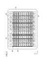
- FIGS. 7A to 9are drawings for explaining the experiment confirming that the deformation of the pattern opening part is suppressed due to the dispersion of tensile force applied to the pattern opening part of each unit mask included in each mask assembly according to each exemplary embodiment.
- FIG. 7Ais a plan view showing the unit masks 200 , 202 , and 203 included in each mask assembly according to each of the embodiments shown in FIGS. 1 to 6 .
- FIG. 7Aalso shows unit masks 11 to 19 according to each comparison examples 1 to 9.
- unit mask 11does not include a dummy pattern or any of the first to third grooves; unit mask 12 has the dummy pattern but none of the first through third grooves; unit mask 13 has a single first groove on one side, but has no dummy pattern and no second and third grooves; unit mask 14 has a single first groove on one side and a dummy pattern, but no second and third grooves; unit mask 15 has a single first groove on one side, a dummy pattern, and second and third grooves; unit mask 16 has a single first groove on one side, a dummy pattern, and the second and third grooves, and a raised area on the other sides where the first groove otherwise would be; unit mask 17 has a single first groove on one side, a dummy pattern, and the third groove, and a raised area on the other sides where the first groove otherwise would be; unit mask 18 has a single first groove on one side, a dummy pattern, a raised area on the other sides where the first groove otherwise would be, but not second or third
- FIG. 7Bis a graph measuring the deformation value of the pattern opening part included in each unit mask when the unit mask is supported by the same frame in the state where the same tensile force is applied to each unit mask shown in FIG. 7A .
- an x-axisrepresents a difference of altitude of a graph showing the measured deformation value of the pattern opening part and a y-axis represents the deformation value of the pattern opening part.
- the deformation values of each pattern opening part included in the unit masks 11 to 19 according to each of comparison examples 1 to 9represents a difference of altitude of 2.3 ⁇ m (micrometer) to 5.4 ⁇ m when the same tensile force is applied to each unit mask 11 to 19 .
- the deformation values of the pattern opening part 220 of the unit mask 200 according to the embodiment shown in FIGS. 1 to 4represents a difference of altitude of 1.6 ⁇ m when tensile force is applied to the unit mask 200 .
- the unit mask 200better suppresses the deformation of the pattern opening part 220 due to the dispersion of the tensile force applied to the pattern opening part 220 than the unit masks 11 to 19 according to each of the comparison examples 1 to 9 was confirmed.
- the deformation values of each pattern opening part included in the unit masks 11 to 19 according to each of comparison examples 1 to 9represents a difference of altitude of 2.3 ⁇ m to 5.4 ⁇ m when the same tensile force is applied to each unit mask 11 to 19 .
- the deformation values of the pattern opening part 220 of the unit mask 202 of FIG. 5represents a difference of altitude of 1.6 ⁇ m when tensile force is applied to the unit mask 202 .
- the fact that the unit mask 202 of FIG. 5better suppresses the deformation of the pattern opening part 220 due to the dispersion of the tensile force applied to the pattern opening part 220 than the unit masks 11 to 19 according to each of the comparison examples 1 to 9 was confirmed.
- each pattern opening part included in the unit masks 11 to 19 according to each of comparison examples 1 to 9represents a difference of altitude of 2.3 ⁇ m to 5.4 ⁇ m when the same tensile force is applied to each unit mask 11 to 19 .
- the deformation values of the pattern opening part 220 of the unit mask 203 of FIG. 6represents a difference of altitude of 1.7 ⁇ m when tensile force is applied to the unit mask 203 .
- the unit mask 203better suppresses the deformation of the pattern opening part 220 due to the dispersion of the tensile force applied to the pattern opening part 220 than the unit masks 11 to 19 according to each of the comparison examples 1 to 9 was confirmed.
- FIG. 8is a graph measuring deformation values per position of each unit mask when the unit masks 200 , 202 , and 203 included in each mask assembly according to the embodiments of FIGS. 1 to 6 and each unit mask 11 to 19 according to each of the comparison examples 1 to 9 are supported by the same frame in the state where the same tensile force is applied.
- an x-axisrepresents the positions of each of the unit masks (a length of each unit mask is set to 200 mm) and a y-axis represents the deformation values of each of the unit masks.
- each unit mask 200 , 202 , and 203is less than the unit masks 11 to 19 according to each of the comparison examples 1 to 9 was confirmed, such that the tensile force applied to each pattern opening part 220 is dispersed and thus, that the deformation of each pattern opening part 220 is suppressed was confirmed.
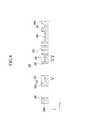
- FIG. 9is a diagram showing pressure applied to the pattern opening part included in each unit mask when the unit masks 200 , 202 , and 203 and each unit mask 11 to 19 according to each of the comparison examples 1 to 9 are supported by the same frame in the state where the same tensile force is applied.
- FIG. 9shows results derived from a simulation experiment using a SIMULIA structure available from Dassault Systemes Co. and ABAQUS, electric and heat analysis tool.
- the colors of FIG. 9means that the tensile force is stronger from red color to blue color.
- each pattern opening part included in each of the unit masks 11 to 19 according to each of the comparison examples 1 to 9are shown by blue when the same tensile force is applied to each unit mask 11 to 19 .
- sides of each pattern opening part 220 included in each unit mask 200 , 202 , and 203are not shown by blue.
- the pressure applied to each pattern opening part 220 included in each unit mask 200 , 202 , and 203 included in the mask assembly according to each of the first, second, and third embodimentsis less than the pattern opening part of the unit masks 11 to 19 according to each of the comparison examples 1 to 9.
- the unit mask 204includes the unit mask main body part 210 , the pattern opening part 220 , the first groove 230 , the second groove 240 , the third groove 250 , and the dummy pattern 264 .
- the dummy pattern 264has a deformed width W on the surface 200 c of the unit mask 204 depending on the strength of the tensile force applied to the pattern opening part 220 neighboring to the dummy pattern 264 .
- the dummy pattern 264is disposed between the outermost pattern opening part 220 and the end 200 a of the unit mask 204 and is formed to penetrate through the unit mask 204 .
- the shown dummy pattern 264has an oval shape on the surface 200 c of the unit mask 204 , such that it has a deformed width W on the surface 200 c of the unit mask 204 .
- the deformed width W of the dummy pattern 240is deformed according to the strength of tensile force applied to the pattern opening part 220 neighboring to the dummy pattern 264 by tensile force applied to the unit mask 204 . As shown in FIG.
- the width W of the dummy pattern 264 corresponding to one side 221 of the pattern opening part 220is gradually narrowed from a portion corresponding to the central portion of one side of the pattern opening part 220 to the outer portion of one side 221 of the pattern opening part 220 .
- the width W of the dummy pattern 264 corresponding to one portion to which a stronger tensile force is applied than other portionsis formed to be wider than the width W of the dummy pattern 264 corresponding to other portions of the pattern opening part 220 .
- the dummy pattern 264has the deformed width W on the surface 200 c of the unit mask 204 according to the strength of the tensile force applied to the pattern opening part 220 , thereby dispersing the tensile force applied to the pattern opening part 220 .
- the tensile force applied to the pattern opening part 220is dispersed by the dummy pattern 264 , such that the deformation of the pattern opening part 220 by the tensile force applied to the unit mask 204 is suppressed.
- the width W corresponding to one portion to which a stronger tensile force is applied than other portions in the entire portion of one side 221 of the pattern opening part 220is formed to be wider than the width W corresponding to other portions of one side 221 .
- the width W corresponding to one portion to which a stronger tensile force is applied than other portions in the entire portion of one side 221 of the pattern opening part 220are formed to be narrower than the width W corresponding to other portions of one side 221 .
- FIG. 12is a cross-sectional view taken along line XII-XII of FIG. 11 .
- the unit mask 205includes unit mask main body part 210 , the pattern opening parts 220 , the first grooves 230 , the second grooves 240 , the third grooves 250 and the dummy pattern 265 .
- the dummy pattern 265has a deformed width W on the surface 200 c of the unit mask 205 according to the strength of the tensile force applied to the pattern opening part 220 neighboring to the dummy pattern 265 .
- the dummy pattern 265is disposed between the outermost pattern opening part 220 and the end 200 a of the unit mask 205 and is formed to be depressed from the surface of the unit mask 205 .
- the dummy pattern 265has an oval shape on the surface 200 c of the unit mask 205 , such that it has a deformed width W on the surface 200 c of the unit mask 205 .
- the deformed width W of the dummy pattern 265is deformed according to the strength of tensile force applied to the pattern opening part 220 neighboring to the dummy pattern 265 by tensile force applied to the unit mask 205 .
- the width W of the dummy pattern 265 corresponding to one side 221 of the pattern opening part 220is gradually narrowed from a portion corresponding to the central portion of one side of the pattern opening part 220 to the outer portion of one side 221 of the pattern opening part 220 .
- the width W of the dummy pattern 265 corresponding to one portion to which a stronger tensile force is applied than other portionsis formed to be wider than the width W of the dummy pattern 265 corresponding to other portions of the pattern opening part 220 .
- the dummy pattern 265has the deformed width W on the surface 200 c of the unit mask 205 according to the strength of the tensile force applied to the pattern opening part 220 , thereby dispersing the tensile force applied to the pattern opening part 220 .
- the tensile force applied to the pattern opening part 220is dispersed by the dummy pattern 265 , such that the deformation of the pattern opening part 220 by the tensile force applied to the unit mask 205 is suppressed.
- the width W corresponding to one portion to which a stronger tensile force is applied than other portions in the entire portion of one side 221 of the pattern opening part 220is formed to be wider than the width W corresponding to other portions of one side 221 .
- the width W corresponding to one portion to which a stronger tensile force is applied than other portions in the entire portion of one side 221 of the pattern opening part 220can be formed to be narrower than the width W corresponding to other portions of one side 221 in other embodiments.
Landscapes
- Engineering & Computer Science (AREA)
- Manufacturing & Machinery (AREA)
- Electroluminescent Light Sources (AREA)
- Physical Vapour Deposition (AREA)
Abstract
Description
Claims (22)
Applications Claiming Priority (2)
| Application Number | Priority Date | Filing Date | Title |
|---|---|---|---|
| KR1020100023898AKR101182239B1 (en) | 2010-03-17 | 2010-03-17 | Mask and mask assembly having the same |
| KR10-2010-0023898 | 2010-03-17 |
Publications (2)
| Publication Number | Publication Date |
|---|---|
| US20110229633A1 US20110229633A1 (en) | 2011-09-22 |
| US8656859B2true US8656859B2 (en) | 2014-02-25 |
Family
ID=44647470
Family Applications (1)
| Application Number | Title | Priority Date | Filing Date |
|---|---|---|---|
| US13/039,035ActiveUS8656859B2 (en) | 2010-03-17 | 2011-03-02 | Mask and mask assembly having the same |
Country Status (5)
| Country | Link |
|---|---|
| US (1) | US8656859B2 (en) |
| JP (1) | JP5427813B2 (en) |
| KR (1) | KR101182239B1 (en) |
| CN (1) | CN102201550B (en) |
| TW (1) | TWI512123B (en) |
Cited By (11)
| Publication number | Priority date | Publication date | Assignee | Title |
|---|---|---|---|---|
| US20130248826A1 (en)* | 2012-03-21 | 2013-09-26 | Samsung Display Co., Ltd. | Flexible display apparatus, organic light emitting display apparatus, and mother substrate for flexible display apparatus |
| US10662519B2 (en) | 2016-07-29 | 2020-05-26 | Boe Technology Group Co., Ltd. | Mask, method for manufacturing the same, and mask assembly |
| US20210108310A1 (en)* | 2018-03-20 | 2021-04-15 | Sharp Kabushiki Kaisha | Film forming mask and method of manufacturing display device using same |
| US20210123129A1 (en)* | 2019-03-28 | 2021-04-29 | Chengdu Boe Optoelectronics Technology Co., Ltd. | Mask and method of manufacturing the same, and mask assembly |
| US20210351351A1 (en)* | 2020-05-09 | 2021-11-11 | Chengdu Boe Optoelectronics Technology Co., Ltd. | Mask Plate |
| US20220064779A1 (en)* | 2020-08-31 | 2022-03-03 | Samsung Display Co., Ltd. | Mask, method of providing the same, and method of providing display panel using mask |
| US20220131075A1 (en)* | 2020-10-26 | 2022-04-28 | Samsung Display Co., Ltd. | Mask assembly and manfucturing method thereof |
| US20220406853A1 (en)* | 2021-06-21 | 2022-12-22 | Dai Nippon Printing Co., Ltd. | Organic device, group of masks, mask, and manufacturing method for organic device |
| US11560616B2 (en)* | 2019-11-05 | 2023-01-24 | Boe Technology Group Co., Ltd. | Mask device, mask plate, and frame |
| US20230037092A1 (en)* | 2021-06-11 | 2023-02-02 | Darwin Precisions Corporation | Metal mask |
| US12031224B2 (en) | 2018-12-31 | 2024-07-09 | Lg Display Co., Ltd. | Mask having a plating layer and method of manufacturing the same |
Families Citing this family (44)
| Publication number | Priority date | Publication date | Assignee | Title |
|---|---|---|---|---|
| KR101309864B1 (en)* | 2010-02-02 | 2013-09-16 | 엘지디스플레이 주식회사 | Mask Assembly |
| KR101742816B1 (en)* | 2010-12-20 | 2017-06-02 | 삼성디스플레이 주식회사 | Mask frame assembly, manufacturing method of the same, and manufacturing method of organic light emitting display device thereused |
| KR101784467B1 (en)* | 2011-01-10 | 2017-10-12 | 삼성디스플레이 주식회사 | Mask stick and the assembling method for mask frame assembly using the same |
| KR101820020B1 (en) | 2011-04-25 | 2018-01-19 | 삼성디스플레이 주식회사 | Mask frame assembly for thin film deposition |
| KR101813549B1 (en)* | 2011-05-06 | 2018-01-02 | 삼성디스플레이 주식회사 | Mask stick and assembling apparatus for a mask frame assembly including the mask stick |
| KR101931770B1 (en)* | 2011-11-30 | 2018-12-24 | 삼성디스플레이 주식회사 | Mask assembly and organic light emitting diode display |
| CN105296920B (en)* | 2012-01-12 | 2018-03-06 | 大日本印刷株式会社 | Layout deposition mask |
| TWI472631B (en)* | 2012-03-30 | 2015-02-11 | Au Optronics Corp | Shadow mask strip |
| KR102024853B1 (en) | 2012-09-03 | 2019-11-05 | 삼성디스플레이 주식회사 | Mask and mask assembly |
| KR102002494B1 (en)* | 2012-11-30 | 2019-07-23 | 삼성디스플레이 주식회사 | Mask frame assembly for thin film deposition |
| CN103911584B (en)* | 2012-12-31 | 2017-07-04 | 上海天马微电子有限公司 | Mask plate |
| JP6086305B2 (en)* | 2013-01-11 | 2017-03-01 | 大日本印刷株式会社 | Vapor deposition mask manufacturing method and vapor deposition mask |
| KR102070219B1 (en) | 2013-05-27 | 2020-01-29 | 삼성디스플레이 주식회사 | Printing mask and apparatus for printing organic light emitting layer |
| TWI480399B (en)* | 2013-07-09 | 2015-04-11 | Metal mask | |
| KR102118641B1 (en) | 2013-07-30 | 2020-06-04 | 삼성디스플레이 주식회사 | Mask and mask assembly |
| JP2015103427A (en)* | 2013-11-26 | 2015-06-04 | 株式会社ジャパンディスプレイ | Manufacturing method of display device |
| KR102219210B1 (en)* | 2013-12-18 | 2021-02-23 | 삼성디스플레이 주식회사 | Mask and mask assembly |
| KR102237428B1 (en)* | 2014-02-14 | 2021-04-08 | 삼성디스플레이 주식회사 | Mask frame assembly and the manufacturing method thereof |
| KR102316680B1 (en)* | 2014-11-24 | 2021-10-26 | 삼성디스플레이 주식회사 | Mask assembly for thin film deposition and the fabrication method thereof |
| KR102441557B1 (en) | 2015-04-28 | 2022-09-08 | 삼성디스플레이 주식회사 | Mask frame assembly, manufacturing method thereof, and display device manufacturing method |
| TWI550108B (en)* | 2015-04-28 | 2016-09-21 | 友達光電股份有限公司 | Mask |
| JP6509630B2 (en)* | 2015-05-13 | 2019-05-08 | 株式会社アルバック | Sheet mask |
| KR102411539B1 (en)* | 2015-10-26 | 2022-06-22 | 삼성디스플레이 주식회사 | Mask assembly, apparatus and method for manufacturing a display apparatus |
| KR102549358B1 (en) | 2015-11-02 | 2023-06-29 | 삼성디스플레이 주식회사 | Deposition mask assembly and method of manufacturing display device using the same |
| KR102375261B1 (en)* | 2016-04-01 | 2022-03-17 | 엘지이노텍 주식회사 | Metal mask for deposition, and oled pannel using the same |
| CN205576262U (en)* | 2016-05-09 | 2016-09-14 | 鄂尔多斯市源盛光电有限责任公司 | Mask plate |
| CN105839052A (en)* | 2016-06-17 | 2016-08-10 | 京东方科技集团股份有限公司 | Mask board and assembling method of mask board |
| KR20180023139A (en)* | 2016-08-24 | 2018-03-07 | 삼성디스플레이 주식회사 | The deposition mask assembly |
| KR102642345B1 (en)* | 2016-09-06 | 2024-02-29 | 삼성디스플레이 주식회사 | Division mask |
| CN118159109A (en)* | 2016-09-13 | 2024-06-07 | Lg伊诺特有限公司 | Metal plate for deposition mask, deposition mask and method for manufacturing the same |
| CN109689921A (en)* | 2016-09-14 | 2019-04-26 | 夏普株式会社 | Mask sheet, vapor deposition mask, and manufacturing method of display panel |
| KR102609073B1 (en)* | 2016-11-30 | 2023-12-05 | 엘지디스플레이 주식회사 | Mask for deposition, manufacturing method of the same |
| JP6376483B2 (en)* | 2017-01-10 | 2018-08-22 | 大日本印刷株式会社 | Vapor deposition mask manufacturing method, vapor deposition mask device manufacturing method, and vapor deposition mask quality determination method |
| CN109423600B (en)* | 2017-08-25 | 2020-01-07 | 京东方科技集团股份有限公司 | Mask strip and preparation method thereof, mask plate |
| JP2019533761A (en)* | 2017-09-27 | 2019-11-21 | アプライド マテリアルズ インコーポレイテッドApplied Materials,Incorporated | Mask apparatus for masking a substrate, apparatus for processing a substrate, and method thereof |
| CN107815641B (en)* | 2017-10-25 | 2020-05-19 | 信利(惠州)智能显示有限公司 | mask |
| KR102559894B1 (en)* | 2018-06-15 | 2023-07-27 | 삼성디스플레이 주식회사 | Mask assembly, deposition apparatus having the same, and method for manufacturing display device using the same |
| KR102642138B1 (en)* | 2018-09-04 | 2024-03-04 | 엘지이노텍 주식회사 | A deposition mask and method for manufacturing of the same |
| KR102688602B1 (en)* | 2019-02-01 | 2024-07-25 | 삼성디스플레이 주식회사 | Mask assembly, apparatus and method having the same for manufacturing a display apparatus |
| CN110396660B (en)* | 2019-08-30 | 2021-10-08 | 昆山国显光电有限公司 | Mask plate and mask plate preparation method |
| CN110747431B (en)* | 2019-11-20 | 2022-04-08 | 京东方科技集团股份有限公司 | Fine mask and fabrication method thereof, combined mask and display substrate |
| KR102799532B1 (en)* | 2020-02-07 | 2025-04-23 | 삼성디스플레이 주식회사 | Mask assembly and method of manufacturing the same |
| CN111500981B (en)* | 2020-06-10 | 2022-06-24 | 京东方科技集团股份有限公司 | Mask plate |
| CN112267092B (en)* | 2020-10-27 | 2023-04-07 | 京东方科技集团股份有限公司 | Mask plate and preparation method thereof |
Citations (28)
| Publication number | Priority date | Publication date | Assignee | Title |
|---|---|---|---|---|
| US5234780A (en)* | 1989-02-13 | 1993-08-10 | Kabushiki Kaisha Toshiba | Exposure mask, method of manufacturing the same, and exposure method using the same |
| US5968686A (en)* | 1996-08-15 | 1999-10-19 | Nec Corporation | Charged-beam exposure mask and charged-beam exposure method |
| US20010004469A1 (en)* | 1997-10-15 | 2001-06-21 | Yoshio Himeshima | Process for manufacturing organic electroluminescent device |
| KR20030021716A (en) | 2001-09-07 | 2003-03-15 | 주식회사 인프라넷 | Apparatus For Expansion Internet Service Through Cellular Phone |
| KR20030093959A (en) | 2002-06-03 | 2003-12-11 | 삼성 엔이씨 모바일 디스플레이 주식회사 | Mask frame assembly for thin layer vacuum evaporation of organic electro luminescence device |
| JP2004055231A (en) | 2002-07-17 | 2004-02-19 | Dainippon Printing Co Ltd | Multi-faced metal mask for vacuum deposition used for manufacturing organic EL devices |
| US20040104197A1 (en)* | 2002-11-29 | 2004-06-03 | Samsung Nec Mobile Display Co., Ltd. | Evaporation mask, method of fabricating organic electroluminescent device using the same, and organic electroluminescent device |
| KR20040054937A (en) | 2002-12-18 | 2004-06-26 | 오리온전기 주식회사 | A mask of organic EL |
| US6858086B2 (en)* | 2001-12-05 | 2005-02-22 | Samsung Oled Co., Ltd. | Tension mask assembly for use in vacuum deposition of thin film of organic electroluminescent device |
| US6893709B2 (en)* | 2000-08-25 | 2005-05-17 | Samsung Sdi Co., Ltd. | Metal mask structure and method for manufacturing thereof |
| KR20050083422A (en) | 2004-02-23 | 2005-08-26 | 오리온전기 주식회사 | Tension mask |
| JP2005302457A (en) | 2004-04-09 | 2005-10-27 | Toray Ind Inc | Deposited mask and its forming method, and manufacturing method for organic electroluminescent equipment |
| US20050264177A1 (en)* | 2004-01-08 | 2005-12-01 | Jin-Koo Chung | Display device, and method of manufacturing the display device |
| CN1722918A (en) | 2004-07-15 | 2006-01-18 | 三星Sdi株式会社 | Mask frame component and organic light-emitting display device fabricated using the component |
| US20060011136A1 (en)* | 2004-07-15 | 2006-01-19 | Semiconductor Energy Laboratory Co., Ltd. | Manufacturing apparatus |
| US20060103289A1 (en)* | 2004-11-18 | 2006-05-18 | Eui-Gyu Kim | Mask frame assembly |
| KR20060100537A (en) | 2005-03-17 | 2006-09-21 | 엘지전자 주식회사 | Mask for manufacturing organic electroluminescent device |
| US20080018236A1 (en)* | 2004-09-08 | 2008-01-24 | Toray Industries, Inc. | Organic Electroluminescent Device and Manufacturing Method Thereof |
| KR20080011571A (en) | 2006-07-31 | 2008-02-05 | 삼성에스디아이 주식회사 | Mask for manufacturing organic light emitting display device |
| JP2008208426A (en) | 2007-02-27 | 2008-09-11 | Seiko Epson Corp | Film-forming mask and method for producing film-forming mask |
| JP2009074160A (en) | 2007-08-24 | 2009-04-09 | Dainippon Printing Co Ltd | Vapor deposition mask and method of manufacturing vapor deposition mask |
| US20090137180A1 (en)* | 2007-11-23 | 2009-05-28 | Samsung Sdi Co., Ltd. | Mask assembly for thin film vapor deposition of flat panel display |
| US7572338B2 (en)* | 2004-11-25 | 2009-08-11 | Samsung Sdi Co., Ltd. | Mask for depositing thin film of flat panel display and method of fabricating the mask |
| US20100055810A1 (en)* | 2008-09-01 | 2010-03-04 | Samsung Mobile Display Co.,Ltd. | Mask for thin film deposition and method of manufacturing oled using the same |
| US7704326B2 (en)* | 2003-12-02 | 2010-04-27 | Sony Corporation | Deposition mask and manufacturing method thereof |
| US20100192856A1 (en)* | 2009-02-05 | 2010-08-05 | Dong-Young Sung | Mask assembly and deposition and apparatus for a flat panel display using the same |
| US20100267227A1 (en)* | 2009-04-16 | 2010-10-21 | Jung-Woo Ko | Mask frame assembly for thin film deposition and associated methods |
| US20110067630A1 (en)* | 2009-09-22 | 2011-03-24 | Jung-Woo Ko | Mask assembly, deposition apparatus for flat panel displays including the same, and associated methods |
- 2010
- 2010-03-17KRKR1020100023898Apatent/KR101182239B1/enactiveActive
- 2011
- 2011-03-02USUS13/039,035patent/US8656859B2/enactiveActive
- 2011-03-09JPJP2011051096Apatent/JP5427813B2/enactiveActive
- 2011-03-14TWTW100108610Apatent/TWI512123B/enactive
- 2011-03-17CNCN201110069548.8Apatent/CN102201550B/enactiveActive
Patent Citations (33)
| Publication number | Priority date | Publication date | Assignee | Title |
|---|---|---|---|---|
| US5234780A (en)* | 1989-02-13 | 1993-08-10 | Kabushiki Kaisha Toshiba | Exposure mask, method of manufacturing the same, and exposure method using the same |
| US5968686A (en)* | 1996-08-15 | 1999-10-19 | Nec Corporation | Charged-beam exposure mask and charged-beam exposure method |
| US20010004469A1 (en)* | 1997-10-15 | 2001-06-21 | Yoshio Himeshima | Process for manufacturing organic electroluminescent device |
| US6893709B2 (en)* | 2000-08-25 | 2005-05-17 | Samsung Sdi Co., Ltd. | Metal mask structure and method for manufacturing thereof |
| KR20030021716A (en) | 2001-09-07 | 2003-03-15 | 주식회사 인프라넷 | Apparatus For Expansion Internet Service Through Cellular Phone |
| US6858086B2 (en)* | 2001-12-05 | 2005-02-22 | Samsung Oled Co., Ltd. | Tension mask assembly for use in vacuum deposition of thin film of organic electroluminescent device |
| KR20030093959A (en) | 2002-06-03 | 2003-12-11 | 삼성 엔이씨 모바일 디스플레이 주식회사 | Mask frame assembly for thin layer vacuum evaporation of organic electro luminescence device |
| JP2004055231A (en) | 2002-07-17 | 2004-02-19 | Dainippon Printing Co Ltd | Multi-faced metal mask for vacuum deposition used for manufacturing organic EL devices |
| JP2004185832A (en) | 2002-11-29 | 2004-07-02 | Samsung Nec Mobile Display Co Ltd | Vapor deposition mask, method of manufacturing organic EL device using the same, and organic EL device |
| US20040104197A1 (en)* | 2002-11-29 | 2004-06-03 | Samsung Nec Mobile Display Co., Ltd. | Evaporation mask, method of fabricating organic electroluminescent device using the same, and organic electroluminescent device |
| US7837528B2 (en)* | 2002-11-29 | 2010-11-23 | Samsung Mobile Display Co., Ltd. | Evaporation mask, method of fabricating organic electroluminescent device using the same, and organic electroluminescent device |
| KR20040054937A (en) | 2002-12-18 | 2004-06-26 | 오리온전기 주식회사 | A mask of organic EL |
| US7704326B2 (en)* | 2003-12-02 | 2010-04-27 | Sony Corporation | Deposition mask and manufacturing method thereof |
| US20050264177A1 (en)* | 2004-01-08 | 2005-12-01 | Jin-Koo Chung | Display device, and method of manufacturing the display device |
| KR20050083422A (en) | 2004-02-23 | 2005-08-26 | 오리온전기 주식회사 | Tension mask |
| JP2005302457A (en) | 2004-04-09 | 2005-10-27 | Toray Ind Inc | Deposited mask and its forming method, and manufacturing method for organic electroluminescent equipment |
| JP2006032342A (en) | 2004-07-15 | 2006-02-02 | Samsung Sdi Co Ltd | Mask frame assembly and organic light emitting display for thin film deposition |
| CN1722918A (en) | 2004-07-15 | 2006-01-18 | 三星Sdi株式会社 | Mask frame component and organic light-emitting display device fabricated using the component |
| US20060011136A1 (en)* | 2004-07-15 | 2006-01-19 | Semiconductor Energy Laboratory Co., Ltd. | Manufacturing apparatus |
| US7802537B2 (en)* | 2004-07-15 | 2010-09-28 | Samsung Mobile Display Co., Ltd. | Mask frame assembly for depositing thin layer and organic light emitting display device manufactured using the mask frame assembly |
| US20080018236A1 (en)* | 2004-09-08 | 2008-01-24 | Toray Industries, Inc. | Organic Electroluminescent Device and Manufacturing Method Thereof |
| US20060103289A1 (en)* | 2004-11-18 | 2006-05-18 | Eui-Gyu Kim | Mask frame assembly |
| US7572338B2 (en)* | 2004-11-25 | 2009-08-11 | Samsung Sdi Co., Ltd. | Mask for depositing thin film of flat panel display and method of fabricating the mask |
| KR20060100537A (en) | 2005-03-17 | 2006-09-21 | 엘지전자 주식회사 | Mask for manufacturing organic electroluminescent device |
| KR20080011571A (en) | 2006-07-31 | 2008-02-05 | 삼성에스디아이 주식회사 | Mask for manufacturing organic light emitting display device |
| JP2008208426A (en) | 2007-02-27 | 2008-09-11 | Seiko Epson Corp | Film-forming mask and method for producing film-forming mask |
| JP2009074160A (en) | 2007-08-24 | 2009-04-09 | Dainippon Printing Co Ltd | Vapor deposition mask and method of manufacturing vapor deposition mask |
| US20090137180A1 (en)* | 2007-11-23 | 2009-05-28 | Samsung Sdi Co., Ltd. | Mask assembly for thin film vapor deposition of flat panel display |
| US8286579B2 (en)* | 2007-11-23 | 2012-10-16 | Samsung Display Co., Ltd | Mask assembly for thin film vapor deposition of flat panel display |
| US20100055810A1 (en)* | 2008-09-01 | 2010-03-04 | Samsung Mobile Display Co.,Ltd. | Mask for thin film deposition and method of manufacturing oled using the same |
| US20100192856A1 (en)* | 2009-02-05 | 2010-08-05 | Dong-Young Sung | Mask assembly and deposition and apparatus for a flat panel display using the same |
| US20100267227A1 (en)* | 2009-04-16 | 2010-10-21 | Jung-Woo Ko | Mask frame assembly for thin film deposition and associated methods |
| US20110067630A1 (en)* | 2009-09-22 | 2011-03-24 | Jung-Woo Ko | Mask assembly, deposition apparatus for flat panel displays including the same, and associated methods |
Cited By (22)
| Publication number | Priority date | Publication date | Assignee | Title |
|---|---|---|---|---|
| US9516745B2 (en)* | 2012-03-21 | 2016-12-06 | Samsung Display Co., Ltd. | Flexible display apparatus, organic light emitting display apparatus, and mother substrate for flexible display apparatus |
| US20170077452A1 (en)* | 2012-03-21 | 2017-03-16 | Samsung Display Co., Ltd. | Flexible display apparatus, organic light emitting display apparatus, and mother substrate for flexible display apparatus |
| US10056575B2 (en)* | 2012-03-21 | 2018-08-21 | Samsung Display Co., Ltd. | Flexible display apparatus, organic light emitting display apparatus, and mother substrate for flexible display apparatus |
| US20130248826A1 (en)* | 2012-03-21 | 2013-09-26 | Samsung Display Co., Ltd. | Flexible display apparatus, organic light emitting display apparatus, and mother substrate for flexible display apparatus |
| US10662519B2 (en) | 2016-07-29 | 2020-05-26 | Boe Technology Group Co., Ltd. | Mask, method for manufacturing the same, and mask assembly |
| US20210108310A1 (en)* | 2018-03-20 | 2021-04-15 | Sharp Kabushiki Kaisha | Film forming mask and method of manufacturing display device using same |
| US11655536B2 (en)* | 2018-03-20 | 2023-05-23 | Sharp Kabushiki Kaisha | Film forming mask and method of manufacturing display device using same |
| US12031224B2 (en) | 2018-12-31 | 2024-07-09 | Lg Display Co., Ltd. | Mask having a plating layer and method of manufacturing the same |
| US20210123129A1 (en)* | 2019-03-28 | 2021-04-29 | Chengdu Boe Optoelectronics Technology Co., Ltd. | Mask and method of manufacturing the same, and mask assembly |
| US11993839B2 (en)* | 2019-03-28 | 2024-05-28 | Chengdu Boe Optoelectronics Technology Co., Ltd. | Mask and method of manufacturing the same, and mask assembly |
| US11560616B2 (en)* | 2019-11-05 | 2023-01-24 | Boe Technology Group Co., Ltd. | Mask device, mask plate, and frame |
| US11930690B2 (en)* | 2020-05-09 | 2024-03-12 | Chengdu Boe Optoelectronics Technology Co., Ltd. | Mask plate |
| US20210351351A1 (en)* | 2020-05-09 | 2021-11-11 | Chengdu Boe Optoelectronics Technology Co., Ltd. | Mask Plate |
| US11885006B2 (en) | 2020-08-31 | 2024-01-30 | Samsung Display Co., Ltd. | Mask, method of providing the same, and method of providing display panel using mask |
| US11618941B2 (en)* | 2020-08-31 | 2023-04-04 | Samsung Display Co., Ltd. | Mask, method of providing the same, and method of providing display panel using mask |
| US20220064779A1 (en)* | 2020-08-31 | 2022-03-03 | Samsung Display Co., Ltd. | Mask, method of providing the same, and method of providing display panel using mask |
| US12312670B2 (en)* | 2020-08-31 | 2025-05-27 | Samsung Display Co., Ltd. | Mask, method of providing the same, and method of providing display panel using mask |
| US11937492B2 (en)* | 2020-10-26 | 2024-03-19 | Samsung Display Co., Ltd. | Mask assembly and manufacturing method thereof |
| US20220131075A1 (en)* | 2020-10-26 | 2022-04-28 | Samsung Display Co., Ltd. | Mask assembly and manfucturing method thereof |
| US20230037092A1 (en)* | 2021-06-11 | 2023-02-02 | Darwin Precisions Corporation | Metal mask |
| US12398452B2 (en)* | 2021-06-11 | 2025-08-26 | Darwin Precisions Corporation | Metal mask |
| US20220406853A1 (en)* | 2021-06-21 | 2022-12-22 | Dai Nippon Printing Co., Ltd. | Organic device, group of masks, mask, and manufacturing method for organic device |
Also Published As
| Publication number | Publication date |
|---|---|
| CN102201550A (en) | 2011-09-28 |
| US20110229633A1 (en) | 2011-09-22 |
| TW201231691A (en) | 2012-08-01 |
| KR101182239B1 (en) | 2012-09-12 |
| KR20110104793A (en) | 2011-09-23 |
| JP2011195960A (en) | 2011-10-06 |
| TWI512123B (en) | 2015-12-11 |
| JP5427813B2 (en) | 2014-02-26 |
| CN102201550B (en) | 2014-04-02 |
Similar Documents
| Publication | Publication Date | Title |
|---|---|---|
| US8656859B2 (en) | Mask and mask assembly having the same | |
| KR102118641B1 (en) | Mask and mask assembly | |
| KR101919467B1 (en) | Mask and mask assembly having the same | |
| US11578400B2 (en) | Fine metal mask having protective portions having protective portion with ratio of thickness reduction equal to single pixel aperture ratio and method for manufacturing the same, mask frame assembly | |
| KR102219210B1 (en) | Mask and mask assembly | |
| US9570715B2 (en) | Mask and mask assembly | |
| US8151729B2 (en) | Mask assembly and method of fabricating the same | |
| US9953828B2 (en) | Frame and mask assembly having the same | |
| KR102544244B1 (en) | Mask frame assembly | |
| KR101097305B1 (en) | Fine deposition mask providing block unit to block dummy slit unit, the manufacturing method of organic light emitting device using the same mask, and the organic light emitting device which is manufactured by the same method | |
| US20110157575A1 (en) | Mask frame assembly for thin layer deposition and organic light emitting display device | |
| CN107523786A (en) | Mask frame and its manufacture method | |
| US20150047560A1 (en) | Mask for depositing an organic layer and mask assembly for the same | |
| CN113875013A (en) | Display panel and display device | |
| WO2021136051A1 (en) | Masking plate and manufacturing method therefor | |
| CN108091667A (en) | Dot structure and the OLED display panel for including the dot structure | |
| TW200411221A (en) | Color filter substrate and display device | |
| CN117769337A (en) | Method of manufacturing deposition mask for organic light emitting diode deposition | |
| CN112420785A (en) | OLED display panel | |
| US20170200772A1 (en) | Substrate and method of manufacturing panel | |
| JP2005353510A (en) | Vacuum deposition mask and method for fixing the same, and method for manufacturing organic EL display panel using the mask | |
| JP2011058066A (en) | Vapor deposition mask and method for manufacturing organic electroluminescence display device | |
| JP3761532B2 (en) | Image display device | |
| KR20060065782A (en) | Shadow Masks for Cathode Ray Tubes | |
| JP2001297714A (en) | Color cathode-ray tube |
Legal Events
| Date | Code | Title | Description |
|---|---|---|---|
| AS | Assignment | Owner name:SAMSUNG MOBILE DISPLAY CO., LTD., KOREA, REPUBLIC Free format text:ASSIGNMENT OF ASSIGNORS INTEREST;ASSIGNORS:HONG, JAE-MIN;KIM, KYUNG-HAN;REEL/FRAME:025939/0989 Effective date:20110302 | |
| AS | Assignment | Owner name:SAMSUNG DISPLAY CO., LTD., KOREA, REPUBLIC OF Free format text:MERGER;ASSIGNOR:SAMSUNG MOBILE DISPLAY CO., LTD.;REEL/FRAME:028840/0224 Effective date:20120702 | |
| STCF | Information on status: patent grant | Free format text:PATENTED CASE | |
| FEPP | Fee payment procedure | Free format text:PAYOR NUMBER ASSIGNED (ORIGINAL EVENT CODE: ASPN); ENTITY STATUS OF PATENT OWNER: LARGE ENTITY | |
| FPAY | Fee payment | Year of fee payment:4 | |
| MAFP | Maintenance fee payment | Free format text:PAYMENT OF MAINTENANCE FEE, 8TH YEAR, LARGE ENTITY (ORIGINAL EVENT CODE: M1552); ENTITY STATUS OF PATENT OWNER: LARGE ENTITY Year of fee payment:8 | |
| MAFP | Maintenance fee payment | Free format text:PAYMENT OF MAINTENANCE FEE, 12TH YEAR, LARGE ENTITY (ORIGINAL EVENT CODE: M1553); ENTITY STATUS OF PATENT OWNER: LARGE ENTITY Year of fee payment:12 |