US8656747B2 - Keying system and method - Google Patents
Keying system and methodDownload PDFInfo
- Publication number
- US8656747B2 US8656747B2US12/174,025US17402508AUS8656747B2US 8656747 B2US8656747 B2US 8656747B2US 17402508 AUS17402508 AUS 17402508AUS 8656747 B2US8656747 B2US 8656747B2
- Authority
- US
- United States
- Prior art keywords
- rack
- racks
- master
- key
- keyway
- Prior art date
- Legal status (The legal status is an assumption and is not a legal conclusion. Google has not performed a legal analysis and makes no representation as to the accuracy of the status listed.)
- Active, expires
Links
Images


Classifications
- E—FIXED CONSTRUCTIONS
- E05—LOCKS; KEYS; WINDOW OR DOOR FITTINGS; SAFES
- E05B—LOCKS; ACCESSORIES THEREFOR; HANDCUFFS
- E05B29/00—Cylinder locks and other locks with plate tumblers which are set by pushing the key in
- E05B29/004—Cylinder locks and other locks with plate tumblers which are set by pushing the key in with changeable combinations
- E—FIXED CONSTRUCTIONS
- E05—LOCKS; KEYS; WINDOW OR DOOR FITTINGS; SAFES
- E05B—LOCKS; ACCESSORIES THEREFOR; HANDCUFFS
- E05B27/00—Cylinder locks or other locks with tumbler pins or balls that are set by pushing the key in
- E05B27/005—Cylinder locks or other locks with tumbler pins or balls that are set by pushing the key in with changeable combinations
- E—FIXED CONSTRUCTIONS
- E05—LOCKS; KEYS; WINDOW OR DOOR FITTINGS; SAFES
- E05B—LOCKS; ACCESSORIES THEREFOR; HANDCUFFS
- E05B27/00—Cylinder locks or other locks with tumbler pins or balls that are set by pushing the key in
- E05B27/0082—Side bar locking
- E—FIXED CONSTRUCTIONS
- E05—LOCKS; KEYS; WINDOW OR DOOR FITTINGS; SAFES
- E05B—LOCKS; ACCESSORIES THEREFOR; HANDCUFFS
- E05B29/00—Cylinder locks and other locks with plate tumblers which are set by pushing the key in
- E05B29/0066—Side bar locking
- E—FIXED CONSTRUCTIONS
- E05—LOCKS; KEYS; WINDOW OR DOOR FITTINGS; SAFES
- E05B—LOCKS; ACCESSORIES THEREFOR; HANDCUFFS
- E05B63/00—Locks or fastenings with special structural characteristics
- E05B63/0034—Locks for use instead of cylinder locks, e.g. locks with cylinder lock profile and a low security operating mechanism
- Y—GENERAL TAGGING OF NEW TECHNOLOGICAL DEVELOPMENTS; GENERAL TAGGING OF CROSS-SECTIONAL TECHNOLOGIES SPANNING OVER SEVERAL SECTIONS OF THE IPC; TECHNICAL SUBJECTS COVERED BY FORMER USPC CROSS-REFERENCE ART COLLECTIONS [XRACs] AND DIGESTS
- Y10—TECHNICAL SUBJECTS COVERED BY FORMER USPC
- Y10T—TECHNICAL SUBJECTS COVERED BY FORMER US CLASSIFICATION
- Y10T70/00—Locks
- Y10T70/70—Operating mechanism
- Y10T70/7441—Key
- Y10T70/7446—Multiple keys
- Y10T70/7463—Master- and change-key
- Y10T70/7469—Change-key shutout
- Y—GENERAL TAGGING OF NEW TECHNOLOGICAL DEVELOPMENTS; GENERAL TAGGING OF CROSS-SECTIONAL TECHNOLOGIES SPANNING OVER SEVERAL SECTIONS OF THE IPC; TECHNICAL SUBJECTS COVERED BY FORMER USPC CROSS-REFERENCE ART COLLECTIONS [XRACs] AND DIGESTS
- Y10—TECHNICAL SUBJECTS COVERED BY FORMER USPC
- Y10T—TECHNICAL SUBJECTS COVERED BY FORMER US CLASSIFICATION
- Y10T70/00—Locks
- Y10T70/70—Operating mechanism
- Y10T70/7441—Key
- Y10T70/7486—Single key
- Y10T70/7508—Tumbler type
- Y10T70/7559—Cylinder type
- Y10T70/7588—Rotary plug
- Y10T70/7593—Sliding tumblers
- Y10T70/7599—Transverse of plug
- Y10T70/7605—Pin tumblers
- Y—GENERAL TAGGING OF NEW TECHNOLOGICAL DEVELOPMENTS; GENERAL TAGGING OF CROSS-SECTIONAL TECHNOLOGIES SPANNING OVER SEVERAL SECTIONS OF THE IPC; TECHNICAL SUBJECTS COVERED BY FORMER USPC CROSS-REFERENCE ART COLLECTIONS [XRACs] AND DIGESTS
- Y10—TECHNICAL SUBJECTS COVERED BY FORMER USPC
- Y10T—TECHNICAL SUBJECTS COVERED BY FORMER US CLASSIFICATION
- Y10T70/00—Locks
- Y10T70/70—Operating mechanism
- Y10T70/7441—Key
- Y10T70/7486—Single key
- Y10T70/7508—Tumbler type
- Y10T70/7559—Cylinder type
- Y10T70/7588—Rotary plug
- Y10T70/7593—Sliding tumblers
- Y10T70/7599—Transverse of plug
- Y10T70/7616—Including sidebar
- Y—GENERAL TAGGING OF NEW TECHNOLOGICAL DEVELOPMENTS; GENERAL TAGGING OF CROSS-SECTIONAL TECHNOLOGIES SPANNING OVER SEVERAL SECTIONS OF THE IPC; TECHNICAL SUBJECTS COVERED BY FORMER USPC CROSS-REFERENCE ART COLLECTIONS [XRACs] AND DIGESTS
- Y10—TECHNICAL SUBJECTS COVERED BY FORMER USPC
- Y10T—TECHNICAL SUBJECTS COVERED BY FORMER US CLASSIFICATION
- Y10T70/00—Locks
- Y10T70/70—Operating mechanism
- Y10T70/7441—Key
- Y10T70/7486—Single key
- Y10T70/7508—Tumbler type
- Y10T70/7559—Cylinder type
- Y10T70/7638—Cylinder and plug assembly
- Y—GENERAL TAGGING OF NEW TECHNOLOGICAL DEVELOPMENTS; GENERAL TAGGING OF CROSS-SECTIONAL TECHNOLOGIES SPANNING OVER SEVERAL SECTIONS OF THE IPC; TECHNICAL SUBJECTS COVERED BY FORMER USPC CROSS-REFERENCE ART COLLECTIONS [XRACs] AND DIGESTS
- Y10—TECHNICAL SUBJECTS COVERED BY FORMER USPC
- Y10T—TECHNICAL SUBJECTS COVERED BY FORMER US CLASSIFICATION
- Y10T70/00—Locks
- Y10T70/70—Operating mechanism
- Y10T70/7441—Key
- Y10T70/7486—Single key
- Y10T70/7508—Tumbler type
- Y10T70/7559—Cylinder type
- Y10T70/7667—Operating elements, parts and adjuncts
- Y10T70/7672—Cylinder
- Y10T70/7678—Adjustable
- Y—GENERAL TAGGING OF NEW TECHNOLOGICAL DEVELOPMENTS; GENERAL TAGGING OF CROSS-SECTIONAL TECHNOLOGIES SPANNING OVER SEVERAL SECTIONS OF THE IPC; TECHNICAL SUBJECTS COVERED BY FORMER USPC CROSS-REFERENCE ART COLLECTIONS [XRACs] AND DIGESTS
- Y10—TECHNICAL SUBJECTS COVERED BY FORMER USPC
- Y10T—TECHNICAL SUBJECTS COVERED BY FORMER US CLASSIFICATION
- Y10T70/00—Locks
- Y10T70/70—Operating mechanism
- Y10T70/7441—Key
- Y10T70/7729—Permutation
- Y10T70/7734—Automatically key set combinations
- Y—GENERAL TAGGING OF NEW TECHNOLOGICAL DEVELOPMENTS; GENERAL TAGGING OF CROSS-SECTIONAL TECHNOLOGIES SPANNING OVER SEVERAL SECTIONS OF THE IPC; TECHNICAL SUBJECTS COVERED BY FORMER USPC CROSS-REFERENCE ART COLLECTIONS [XRACs] AND DIGESTS
- Y10—TECHNICAL SUBJECTS COVERED BY FORMER USPC
- Y10T—TECHNICAL SUBJECTS COVERED BY FORMER US CLASSIFICATION
- Y10T70/00—Locks
- Y10T70/70—Operating mechanism
- Y10T70/7441—Key
- Y10T70/7729—Permutation
- Y10T70/774—Adjustable tumblers
Definitions
- the present inventionrelates generally to lock cylinders and particularly to lock cylinders that can be rekeyed. More particularly, the invention relates to a keying system and method.
- master shimsare positioned in between the pins of the lock cylinder to establish a shear line for the master key and user keys.
- the consumerreplaces the pins and adds shims to convert the lock cylinder to a master keyed cylinder. This may be a complicated process for some consumers.
- the present inventionovercomes these and other disadvantages of conventional lock cylinders and master keying systems.
- the present inventionin one form thereof, is directed to a keying method.
- the methodincludes providing a cylinder body and a plug assembly disposed in the cylinder body, the plug assembly having a keyway, a plug body and a carrier sub-assembly disposed adjacent the plug body, the carrier sub-assembly being moveable parallel to the longitudinal axis of the cylinder body between a first position and a retracted position, the plug assembly including a plurality of pins and a plurality of racks for respectively engaging the plurality of pins, each rack of the plurality of racks having a locking bar-receiving groove.
- the methodfurther includes moving the carrier sub-assembly that carries the plurality of racks to the retracted position to decouple the plurality of racks from the plurality of pins; inserting a rack removal key in the keyway, the rack removal key having a cut that lifts the plurality of pins by a first amount; releasing the carrier sub-assembly from the retracted position to reengage the plurality of racks with the plurality of pins; disengaging a locking bar from the locking bar-receiving groove of each rack of the plurality of racks to decouple the racks; removing the rack removal key from the keyway; inserting a rack removal tool into the keyway, the rack removal tool having a cut that lifts the plurality of pins by a second amount greater than the first amount; moving the carrier sub-assembly to the retracted position to decouple the plurality of racks from the plurality of pins; removing each rack to be replaced from a corresponding access hole on the
- the present inventionin another form thereof, is directed to a master keying method.
- the methodincludes providing a lock cylinder having a cylinder body with a longitudinal axis, and a plug assembly disposed in the cylinder body, the plug assembly having a keyway, a plug body having a plurality of protrusion features, and a carrier sub-assembly disposed adjacent the plug body, the carrier sub-assembly being moveable parallel to the longitudinal axis of the cylinder body between a first position and a retracted position, the plug assembly including a plurality of pins and a plurality of racks for engaging the pins, each rack of the plurality of racks having a locking bar-receiving groove and a protrusion receiving groove.
- the methodfurther includes inserting a valid master key into the keyway; rotating the valid master key to rotate the plug assembly from an original position to a first position in a first rotational direction; moving the carrier sub-assembly to a retracted position to decouple the plurality of racks from the plurality of pins and position the protrusion receiving groove of each rack over a corresponding protrusion feature on the plug body; removing the valid master key from the keyway; inserting a rack removal key in the keyway, the rack removal key having a cut that lifts the plurality of pins by a first amount; rotating the plug assembly to a second position in the first rotational direction to release the carrier sub-assembly from the retracted position to reengage the plurality of racks with the plurality of pins; removing a side plug from the cylinder body to disengage a locking bar from the locking bar-receiving groove of each rack, thereby decoupling all of the plurality of racks from each other rack; removing the rack removal key
- the present inventionin another form thereof, is directed to a keying system.
- the systemincludes a cylinder body having a longitudinal axis.
- a plug assemblyis disposed in the cylinder body.
- the plug assemblyhas a keyway.
- the plug assemblyincludes a plug body and a carrier sub-assembly disposed adjacent the plug body.
- the carrier sub-assemblyis moveable parallel to the longitudinal axis of the cylinder body between a first position and a second position.
- the plug assemblyincludes a plurality of pins and a plurality of racks for selectively engaging the plurality of pins.
- Each rack of the plurality of rackshas a first locking bar-receiving groove along a neutral axis and at least a second locking bar-receiving groove spaced from the neutral axis.
- a spacing of the second locking bar-receiving groove from the neutral axis of a first rack of the plurality of racksis different from a spacing of the second locking bar-receiving groove from the neutral axis of at least one other of the plurality of racks.
- the present inventionin still another form thereof, is directed to a kit for a master keying system.
- the kitincludes a plurality of replacement master racks, a rack removal key for insertion into a keyway, and a rack removal tool for insertion into the keyway.
- the rack removal keyhas a first cut defining a first lift amount.
- the rack removal toolhas a second cut defining a second lift amount. The second lift amount is greater than the first lift amount.
- the present inventionin still another form thereof, is directed to a keying method, including providing a plurality of replacement master racks to be installed in a movable carrier assembly of a lock cylinder; and manipulating the movable carrier assembly with a rack removal key and a rack removal tool, each of the rack removal key and the rack removal tool being configured for insertion into a keyway of the lock cylinder, the rack removal key having a first cut defining a first lift amount, and the rack removal tool having a second cut defining a second lift amount, the second lift amount being greater than the first lift amount.
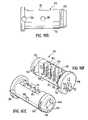
- FIG. 1illustrates a lock cylinder according to the present invention.
- FIG. 2is an exploded view of the lock cylinder of FIG. 1 .
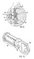
- FIG. 3is a perspective view of a plug assembly illustrating a carrier sub-assembly with a locking bar disposed in a locking position to lock the plug assembly in a lock cylinder body.
- FIG. 4is a top plan view of the plug assembly of FIG. 3 .
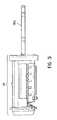
- FIG. 5is a partially broken away side view of the plug assembly of FIG. 3 .
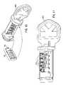
- FIG. 6is a partially exploded view of the plug assembly of FIG. 3 .
- FIG. 7is a section view through the plug assembly of FIG. 3 and a cylinder body, the section being taken transversely at one of the pins and illustrating the positioning of the pin, a rack, and the locking bar relative to each other and the cylinder body in a locked configuration.
- FIG. 8is a perspective view of the plug assembly of FIG. 3 with a valid key inserted therein and illustrating the locking bar disposed in an unlocking position to allow the plug assembly to rotate in the lock cylinder body.
- FIG. 9is a top plan view of the plug assembly of FIG. 8 .
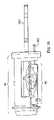
- FIG. 10is a partially broken away side view of the plug assembly of FIG. 8 .
- FIG. 11is a partially exploded view of the plug assembly of FIG. 8 .
- FIG. 12is a section view through the plug assembly of FIG. 8 and a cylinder body, the section being taken transversely at one of the pins and illustrating the positioning of the pin, the rack, and the locking bar relative to each other and the cylinder body in an unlocked configuration.
- FIG. 13is a perspective view similar to FIG. 8 but with the carrier assembly moved axially to a rekeying position.
- FIG. 14is a top plan view of the plug assembly of FIG. 13 .
- FIGS. 15 a - 15 eare various views of a cylinder body for use in the present invention.
- FIGS. 16 a - 16 fare various views of the cylinder plug body for use in the present invention.
- FIGS. 17 a - 17 fare various view of the carrier for use in the present invention.
- FIGS. 18 a - 18 bare views of a rack for use in the present invention.
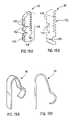
- FIGS. 19 a - 19 bare views of a spring catch for use in the present invention.
- FIGS. 20 a - 20 bare views of a pin for use in the present invention.
- FIGS. 21 a - 21 bare views of a locking bar for use in the present invention.
- FIGS. 22 a - 22 dare views of a spring retaining cap for use in the present invention.
- FIG. 23is an exploded perspective view of an alternative embodiment of the invention.
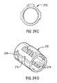
- FIGS. 24 a - 24 eare views of an alternative embodiment of the lock cylinder housing.
- FIG. 25is a transverse section view taken through an alternative embodiment of the present invention.
- FIGS. 26 a - 26 bare views of an alternative embodiment of the spring catch.
- FIGS. 27 a - 27 eare views of an alternative embodiment of the carrier.
- FIGS. 28 a - 28 bare views of an alternative embodiment of the pin.
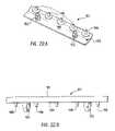
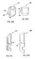
- FIGS. 29 a - 29 bare views of an alternative embodiment of the rack.
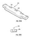
- FIGS. 30 a - 30 bare views of an alternative embodiment of the locking bar.
- FIG. 31shows a rack removal key in accordance with the present invention.
- FIG. 32shows a rack removal tool in accordance with the present invention.
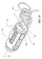
- FIG. 33shows a lock cylinder having a plug assembly and keyway.
- FIG. 34shows a plurality of master racks in accordance with the present invention.
- FIG. 35shows the position of the plurality of master racks when a tenant key is inserted into the keyway.
- FIGS. 36A-36Cshow a detailed flowchart of one embodiment of a method for rekeying a lock cylinder of the master keying system in accordance with the present invention.
- FIG. 37shows the position of the carrier sub-assembly as it is pushed to the retracted position.
- FIG. 38shows the placement of the master racks after the carrier sub-assembly is pushed to the retracted position.
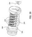
- FIG. 39shows the placement of the master racks with the master key removed from the keyway.
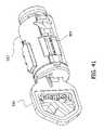
- FIG. 40shows the rack removal key inserted in the keyway of the plug assembly.
- FIG. 41shows the removable side panel removed from the cylinder body, exposing the locking bar.
- FIG. 42shows the position of the plurality of master racks with the rack removal key inserted in the keyway.
- FIG. 43shows the plurality of master racks positioned above the corresponding protrusion feature of the plug body.
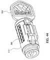
- FIG. 44shows the rack access holes in the cylinder body.
- FIG. 45shows a plurality of replacement master racks.
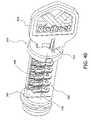
- FIG. 46shows the carrier sub-assembly released from the retracted position to engage the plurality of replacement master racks with the plurality of pins.
- FIG. 47shows the plurality of replacement master racks with the corresponding protrusion grooves lined up with the corresponding protrusion features on the plug body.
- FIG. 48shows the master locking bar-receiving grooves of the master racks positioned to receive the locking bar.
- FIG. 49shows the removable side panel reinstalled on the cylinder body.
- FIG. 50shows the plug assembly in the learn mode position.
- FIG. 51shows the individual positions of each of the plurality of replacement master racks when the carrier sub-assembly is moved to the retracted position.
- FIG. 52shows the plug body rotated by a new master key in the second rotational direction back to the original position so as to reengage the plurality of replacement master racks with the plurality of pins.
- FIG. 1-2A lock cylinder 10 according to the present invention is illustrated in FIG. 1-2 .
- the lock cylinder 10includes a longitudinal axis 11 , a lock cylinder body 12 , a plug assembly 14 and a retainer 16 .
- the plug assembly 14is in the home position relative to the cylinder body 12 .
- the intermediate portion 46includes a main portion 70 formed as a cylinder section and having a first longitudinal planar surface 72 and a plurality of channels 74 for receiving the spring-loaded pins 38 .
- the channels 74extend transversely to the longitudinal axis of the plug body 40 and parallel to the planar surface 72 .
- a second planar surface 76extends perpendicular to the first planar surface 72 and defines a recess 80 for receiving a retaining cap 82 ( FIGS. 2 and 22 a - 22 d ).
- the channels 74extend from the second planar surface 76 partially through the plug body 40 , with the sidewalls of the channels open to the first planar surface 72 .
- the first planar surface 72further includes a plurality of bullet-shaped, rack-engaging features 78 .
- a bore 86 for receiving a spring-loaded detent ball 36 ( FIG. 2 )extends radially inwardly from opposite the first planar surface 72 .
- the carrier sub-assembly 42( FIGS. 2 , 6 and 10 ) includes a carrier 90 ( FIGS. 17 a - 17 e ), a plurality of racks 92 ( FIGS. 18 a - 18 b ), a spring catch 96 ( FIGS. 19 a - 19 b ), a spring-loaded locking bar 94 ( FIGS. 21 a - 21 b ), and a return spring 98 ( FIG. 2 ).
- the carrier 90includes a body 100 in the form of a cylinder section that is complementary to the main portion 70 of the plug body 40 , such that the carrier 90 and the main portion 70 combine to form a cylinder that fits inside the lock cylinder body 12 .
- the carrier 90includes a curved surface 102 and a flat surface 104 .
- the curved surface 102includes a locking bar recess 106 and a spring catch recess 108 .
- the locking bar recess 106further includes a pair of return spring-receiving bores 109 ( FIG. 17 c ) for receiving the locking bar return springs.
- the flat surface 104includes a plurality of parallel rack-receiving slots 103 extending perpendicular to the longitudinal axis of the carrier.
- a semi-circular groove 111extends along the flat surface 104 parallel to the longitudinal axis of the carrier 90 .
- the back end of the carrier 90includes a recess 112 for receiving the return spring 98 .
- Each spring-loaded pin 38includes a pin 113 and a biasing spring 115 .
- the pins 113illustrated in FIGS. 20 a - 20 b , are generally cylindrical with annular gear teeth 114 and a central longitudinal bore 116 for receiving biasing springs 115 ( FIG. 2 ).
- the racks 92illustrated in FIGS. 18 a - 18 b , include a pin-engaging surface 118 having a plurality of gear teeth 122 configured to engage the annular gear teeth 114 on the pins 113 , as illustrated in FIGS. 7 and 12 , and a semi-circular recess 124 for engaging the bullet-shaped, rack-engaging features 78 on the planar surface 72 , as illustrated in FIG. 12 .
- the racks 92further include a second surface 126 that includes a plurality of anti-pick grooves 128 and a pair of locking bar-engaging grooves 132 .
- the spring-loaded locking bar 94illustrated in FIGS. 21 a - 22 b , is sized and configured to fit in the locking bar recess 106 in the carrier 90 and includes a triangular edge 134 configured to fit in the V-shaped locking bar-engaging groove 29 . Opposite the triangular edge 134 , the locking bar 94 includes a pair of longitudinally extending gear teeth 136 configured to engage the locking bar-engaging grooves 132 formed in the racks 92 , as illustrated in FIG. 12 .
- the spring-retaining cap 82illustrated in FIGS. 22 a - 22 d , includes a curvilinear portion 140 having an upper surface 142 and a lower surface 144 .
- the thickness of the curvilinear portion 140is set to allow the curvilinear portion 140 to fit in the recess 80 with the upper surface 142 flush with the intermediate portion 46 of the plug body 40 , as illustrated in FIGS. 7 and 12 .
- a plurality of spring alignment tips 146extend from the lower surface 144 to engage the springs 115 .
- a pair of cap retaining tips 152extend from the lower surface 144 to engage alignment openings 154 formed in the plug body 40 ( FIGS. 16 e - 16 f ).
- the pins 113 and spring 115are disposed in the channels 74 of the plug body 40 .
- the spring-retaining cap 82is placed in the recess 80 , with the cap retaining tips 152 disposed in the alignment openings 154 and the spring alignment tips 146 engaged with the springs 115 .
- the carrier sub-assembly 42is assembled by placing the racks 92 into the slots 103 and the spring-loaded locking bar 94 into the locking bar recess 106 , with the gear teeth 136 engaging the locking bar-engaging grooves 132 formed in the racks 92 .
- the spring catch 96is disposed in the spring catch recess 108 of the carrier 90 .
- a valid key 160is inserted into the keyway 52 , the return spring 98 is compressed into the return spring recess 112 , and the carrier sub-assembly is placed adjacent the plug body 40 , as illustrated in FIG. 3 .
- the plug assembly 14is placed in the lock cylinder body 12 and the retainer 16 is disposed in the slots 66 formed in the plug body 40 to retain the plug assembly 14 in the cylinder body 12 .
- the lock cylinder 10is now keyed to the valid key 160 .
- FIGS. 4-7The properly keyed lock cylinder 10 , without the key 160 inserted, is illustrated in FIGS. 4-7 .
- the pins 113are biased to the bottom of the channels 74 and, based on the cut of the key 160 , the racks 92 are disposed at various positions in the slots 103 of the carrier 90 .
- the locking bar 94extends from the carrier 90 to engage the groove 29 in the cylinder body 12 to prevent the plug assembly 14 from rotating in the cylinder body 12 and the racks 92 engage the pins 113 , as illustrated in FIG. 4 .
- the bullet-shaped features 78are misaligned with the groove 111 in the racks 92 and therefore interfere with movement of the racks 92 parallel to the longitudinal axis of the lock cylinder 10 , preventing the lock cylinder 10 from being rekeyed.
- FIGS. 8-12The internal configuration of a lock cylinder 10 with the valid key 160 inserted therein at the home position is illustrated in FIGS. 8-12 .
- the locking bar 94is free to cam out of the groove 29 in the cylinder body 12 , as depicted in FIGS. 8 , 9 and 12 .
- the bits of the key 160lift the pins 113 in the channels 74 and thereby re-position the racks 92 in the slots 103 .
- the racks 92are disposed to align the locking bar-engaging grooves 132 with the extended gear teeth 136 on the locking bar 94 .
- the locking bar 94is free to cam out of the groove 29 as the key 160 is rotated.
- the bullet-shaped features 78are aligned with the groove 111 in the racks 92 , as illustrated in FIG. 12 , allowing the racks 92 , and the carrier 90 , to move parallel to the longitudinal axis of the lock cylinder 10 .
- the valid key 160is inserted into the keyway 52 , as illustrated in FIGS. 13-14 and rotated approximately 45° counterclockwise from the home position until the spring catch 96 moves into the second detent recess 32 formed in the cylinder body 12 .
- a paperclip or other pointed device 162is inserted into the tool opening 54 and pushed against the carrier 90 to move the carrier 90 parallel to the longitudinal axis of the lock cylinder 10 until the spring catch 96 moves into the first detent recess 30 , and the pointed device 162 is removed. With the spring catch 96 disposed in the first detent recess 30 , the racks 92 are disengaged from the pins 113 , as illustrated in FIG. 14 .
- FIGS. 23-29An alternative embodiment 210 of the invention is illustrated in FIGS. 23-29 .
- the alternative embodimentincludes the same components, as illustrated in FIG. 23 , but several of the components have been modified. Functionally, both embodiments are the same.
- the modified housing 212illustrated in FIGS. 23 and 24 , includes a plurality of apertures 214 running longitudinally along the bottom thereof and a pair of vertical grooves 216 , 218 formed in the housing sidewall.
- the sidewallincludes a removable side panel 220 .
- the rectangular holes 214are positioned to allow the use of a manual override tool.
- the center groove 216includes an aperture 222 extending through the housing sidewall. The aperture 222 allows a user to move the locking bar during a manual override operation.
- the side panel 220provides access for performing certain operations while changing the master key of the lock cylinder.
- the modified pin biasing springs 226illustrated in FIGS. 23 and 25 , include a non-constant diameter, with the last few coils at each end of the springs 226 having a reduced diameter.
- the taperingallows for a greater spring force in a smaller physical height.
- the modified spring catch 228illustrated in FIGS. 23 and 26 , includes a central U-shaped portion 230 and a pair of arms 232 extending from the U-shaped portion 230 .
- the modified carrier 236illustrated in FIGS. 23 and 27 , includes means for retaining the spring catch 228 in the spring catch recess 238 .
- thisincludes a guide 240 projecting outwardly in the center of the spring catch recess 238 and a pair of anchors 242 radially offset from the guide 240 .
- the guide 240prevents the spring catch 228 from moving transversely in the recess 238 while permitting it to move radially outwardly to engage the housing 12 , 212 as described above.
- the anchors 242engage the arms 232 of the spring catch 228 and prevent the arms 232 from splaying outwardly, thereby directing the compressive force of the spring catch 228 to extend the U-shaped portion 230 outwardly to engage the housing 12 , 212 .
- the modified pins 244illustrated in FIGS. 23 and 28 , include a single gear tooth 246 instead of the plurality of gear teeth of the pins 113 described above.
- the single gear tooth 246which preferably includes beveled sides 248 , provides for a smoother engagement with the racks during the rekeying process.
- the modified racks 250illustrated in FIGS. 23 and 29 , include beveled gear teeth to improve the engagement with the pins during the rekeying process.
- the pair of locking bar-engaging grooves 132 in the racks 92are replaced with a single locking bar-engaging groove 251 .
- the modified locking bar 252illustrated in FIGS. 23 and 30 , is thinner than locking bar 94 and replaces the pair of gear teeth 136 with a single gear tooth 256 and rounds out the triangular edge 134 .
- the thinner designreduces any rocking of the locking bar 252 in the locking bar recess 106 .
- a kitmay be provided that facilitates the rekeying of a lock cylinder with respect to a master keying system.
- the kitmay include, for example, a rack carrier moving tool 162 , such as an elongate pin, e.g., a straightened portion of a paper clip, for moving a rack carrier, such as for example carrier 236 , in a longitudinal direction of the lock cylinder, such as that of the lock cylinder 210 of the alternative embodiment.
- the rack carrier moving tool 162may be provided by the user.
- the kitincludes a rack removal key 310 (shown in FIG. 31 ) and a rack removal tool 312 (shown in FIG. 32 ).
- the rack removal key 310is configured for insertion into a keyway, such as the keyway 314 of the plug assembly 316 shown in FIG. 33 .
- the rack removal key 310has a first cut 318 defining a surface 320 having a first lift amount 322 for lifting the pins, e.g., pins 244 , and in turn, the racks, e.g., racks 250 , which may be installed in the lock cylinder 210 , and more precisely, installed in the plug assembly 316 .
- the rack removal tool 312is also configured for insertion into the keyway 314 .
- the rack removal tool 312has a second cut 326 defining a surface 328 having a second lift amount 330 for lifting the pins, e.g., pins 244 , and in turn, the racks, e.g., racks 250 , which may be installed in the lock cylinder 210 , and more precisely, installed in the plug assembly 316 .
- the second lift amount 330 of the rack removal tool 312is greater than the first lift amount 322 of the rack removal key 310 .
- the kitfurther includes a plurality of master racks 332 , which may be replacement master racks, including, for example, individual master racks 332 A- 332 E.
- each master rack of the plurality of master racks 332has a first locking bar-receiving groove 334 .
- the first locking bar-receiving groove 334is located along a neutral axis 336 .
- At least a second locking bar-receiving groove 338 A, 338 B, 338 C, 338 D, 338 E, respectively,may be variously spaced from the neutral axis 336 .
- each master rack of the plurality of replacement master rackshas a protrusion groove 335 for receiving the protrusion features, e.g., rack engaging features, 344 , on the plug body 340 of the plug assembly 316 (see FIG. 23 ), and which are spaced a common distance from neutral axis 336 .
- the configuration of the plurality of master racks 332 , and the various spacing of the second locking bar-receiving grooves, e.g., 338 A, 338 B, 338 C, 338 D, 338 E, respectively, from the neutral axis 336 for each master rack 332 A- 332 Emay be correlated to a particular master key.
- the second locking bar-receiving groove 338 A- 338 Emay be anywhere above or below the first locking bar-receiving groove 334 .
- the purpose of the second locking bar-receiving groove 338 A- 338 Eis for the master keying capability of the lock cylinder 210 .
- FIG. 35shows the position of the plurality of master racks 332 when a tenant key has been inserted in the keyway 314 of the plug assembly 316 .
- the plug assembly 316is still able to rotate in the cylinder body 212 , with the locking bar 364 engaging individual grooves of the plurality of master racks 332 .
- the lock cylinder 210cannot be rekeyed.
- FIGS. 36A-36Cshow a detailed flowchart of one embodiment of a method for rekeying the lock cylinder 210 of the master keying system, which may utilize components of the kit described above in relation to FIGS. 31-35 . This method will be described with further reference to FIGS. 37-52 .
- a lock cylinder 210is provided for rekeying.
- the lock cylinder 210includes a cylinder body 212 with a longitudinal axis 342 , and with the plug assembly 316 disposed in the cylinder body 212 .
- the plug assembly 316includes the keyway 314 , the plug body 340 having the plurality of protrusion features 344 , and a carrier sub-assembly 346 disposed adjacent the plug body 340 .
- the carrier sub-assembly 346is moveable parallel to the longitudinal axis 342 of the cylinder body 212 between a first position, e.g., an initial position, and a second position, e.g., a retracted position.
- the plug assembly 316includes the plurality of pins 244 and the plurality of racks 348 , as shown in FIG. 23 , or alternatively the plurality of master racks 332 , as shown in FIG. 34 , for engaging the pins 244 .
- Each rack of the plurality of racks 348has a locking bar-receiving groove 350 and a protrusion groove 352 .
- a valid master key 354is inserted into the keyway 314 .
- step S 104as depicted in FIG. 33 , the valid master key 354 is rotated to rotate the plug assembly 316 from an original position along the x-axis by approximately 90 degrees in a first rotational direction, e.g., counterclockwise, respective to the X-axis.
- a first rotational directione.g., counterclockwise
- the carrier sub-assembly 346which includes master racks 332 in the configuration of FIG. 38 , is moved in a direction 356 to a retracted position to decouple the plurality of master racks 332 , as shown, from the plurality of pins 244 and position the protrusion groove 335 of each rack 332 A- 332 E over a corresponding protrusion feature 344 (see also FIG. 34 ) on the plug body 340 .
- the movement of carrier sub-assembly 346may be effected by rack carrier moving tool 162 by inserting tool 162 into the rekeying tool opening 358 in the plug face 360 of the plug assembly 316 .
- FIG. 37shows the position of the carrier sub-assembly 346 , which includes the plurality of master racks 332 , as it is pushed backwards by tool 162 to the retracted position.
- FIG. 38shows the placement of the plurality of master racks 332 after carrier sub-assembly 346 is pushed back to the retracted position. As shown, the protrusion engaging groove of each of the master racks 332 rides up over the corresponding protrusion feature 344 on the plug body 340 .
- the valid master key 354is removed from the keyway 314 .
- the protrusion groove 335 of each of the plurality of master racks 332will remain over the corresponding protrusion feature 344 on the plug body 340 , and the pins 244 will ride up against a ledge of the plug body 340 .
- the rack removal key 310is inserted in the keyway 314 , as shown in FIG. 40 .
- the rack removal key 310has a cut 318 that lifts the plurality of pins 244 by a first amount, and in turn lifts the plurality of master racks 332 .
- the relatively low cut 318 of rack removal key 310in comparison to the cut 326 of the rack removal tool 312 , is selected to locate all the racks at the neutral axis 336 .
- the plug assembly 316is rotated by an additional 90 degrees in the first rotational direction, e.g., counterclockwise, by a corresponding rotation of the rack removal key 310 , so as to release the carrier sub-assembly 346 from the retracted position to reengage the plurality of master racks 332 with the plurality of pins 244 .
- the plug catch 228disengages from the slot (not shown) on the cylinder body 212 allowing the carrier spring 362 to push the carrier 236 of the carrier sub-assembly 346 forward to the first position, e.g., the initial position.
- the plurality of master racks 332are reengaged with the tooth, or teeth, of the respective plurality of pins 244 .
- a removable side panel 220is removed (see FIG. 23 ) from the cylinder body 212 to disengage the locking bar 364 (see FIG. 41 ) from the locking bar-receiving groove of each rack 332 A- 332 E, thereby decoupling all of the plurality of master racks 332 from each other rack.
- the position of the plurality of master racks 332is as shown in FIG. 42 .
- step S 116the rack removal key 310 is removed from the keyway 314 .
- the rack removal tool 312is inserted into the keyway 314 .
- the rack removal tool 312has a cut 326 that lifts the plurality of pins 244 by a second amount greater than the first amount associated with the cut 318 of the rack removal key 310 .
- the rack removal tool 312lifts the plurality of master racks 332 to a position such that the entirety of the plurality of master racks 332 , including the protrusion grooves 335 , will be above the protrusion features 344 on the plug body 340 .
- the carrier sub-assembly 346is subsequently moved to the retracted position to decouple the plurality of master racks 332 from the plurality of pins 244 and position each rack 332 A- 332 E above the corresponding protrusion feature 344 on the plug body 340 , as shown in FIG. 43 .
- the movement of carrier sub-assemblymay be effected by rack carrier moving tool 162 , by inserting tool 162 into the rekeying tool opening 358 in the plug face 360 of the plug assembly 316 .
- one or more of the current plurality of master racks 332 A- 332 Emay now be removed from access holes 366 in the cylinder body 212 (see FIG. 44 ).
- each of the plurality of master racks 332will be replaced by a corresponding plurality of replacement master racks 368 shown in FIG. 45 , individually identified as 368 A- 368 E.
- each of the plurality of replacement master racks 368is inserted through a respective access hole 366 in cylinder body 212 .
- the position of the plurality of replacement master racks 368 after the master racks 368 are inserted through the access holes 366will be substantially like that of the plurality of master racks 332 shown in FIG. 43 , wherein the plurality of replacement master racks 368 will be above, e.g., sitting on top of, the protrusion features 344 of the plug body 340 .
- the carrier sub-assembly 346is released from the retracted position to engage the plurality of replacement master racks 368 with the plurality of pins 244 , as shown in FIG. 46 . Since no detent is provided in this example to hold the carrier sub-assembly 346 in the retracted position when the plug body 340 has been rotated by approximately 180 degrees, the carrier sub-assembly 346 is manually held in the retracted position, and manually released from the retracted position to move the plurality of replacement master racks 368 forward to clear the protrusion features 344 on plug body 340 .
- step S 128the rack removal tool 312 is removed from the keyway 314 .
- the rack removal key 310is reinserted in the keyway 314 .
- Thissets the position of the plurality of pins 244 and in turn lines up the master locking bar-receiving grooves 370 (see FIG. 45 ) along the neutral axis 336 of each of the plurality of replacement master racks 368 , and in turn lines up the corresponding protrusion grooves 372 with the corresponding protrusion feature 344 on the plug body 340 , as shown in FIG. 47 .
- the master locking bar-receiving grooves of the master racksare now positioned to receive the locking bar 364 , as shown in FIG. 48 .
- step S 132without removing the rack removal key 310 , the removable side panel 220 is reinstalled as shown in FIG. 49 on to the cylinder body 212 so that the locking bar 364 engages with the master locking bar-receiving groove 370 of each replacement master rack 368 A- 368 E of the plurality of replacement master racks 368 , thereby coupling all of the plurality of replacement master racks 368 together.
- step S 134the plug assembly 316 is rotated by approximately 90 degrees in a second rotational direction, e.g., clockwise, opposite to the first rotational direction, by a corresponding rotation of rack removal key 310 . This places the plug assembly in the learn mode position, as shown in FIG. 50 .
- the carrier sub-assembly 346is subsequently moved to the retracted position to decouple the plurality of replacement master racks 368 from the plurality of pins 244 and position the protrusion grooves 372 of each replacement master rack 368 A- 368 E over a corresponding protrusion feature 344 on the plug body 340 .
- the movement of carrier sub-assemblymay be effected by the rack carrier moving tool 162 , by inserting the tool 162 into the rekeying tool opening 358 in the plug face 360 of the plug assembly 316 .
- the individual positions of each of the plurality of replacement master racks 368is shown in FIG. 51 .
- step S 138the rack removal key 310 is removed from the keyway 314 .
- a new master key 374is inserted into the keyway 314 , as shown in FIG. 52 .
- step S 142the plug body 340 is rotated in the second rotational direction back to the original position, as shown in FIG. 52 , by a corresponding rotation of the new master key 374 , to release the carrier sub-assembly 346 from the retracted position to reengage the plurality of replacement master racks 368 with the plurality of pins 244 , to thereby learn the cut of the new master key 374 , thereby completing the rekeying of lock cylinder 210 to the new master key 374 .
Landscapes
- Physics & Mathematics (AREA)
- Electromagnetism (AREA)
- Engineering & Computer Science (AREA)
- Structural Engineering (AREA)
- Manufacturing Of Electrical Connectors (AREA)
- Automatic Assembly (AREA)
- Lock And Its Accessories (AREA)
- Quick-Acting Or Multi-Walled Pipe Joints (AREA)
- Slide Fasteners (AREA)
- Automatic Tool Replacement In Machine Tools (AREA)
- Vehicle Cleaning, Maintenance, Repair, Refitting, And Outriggers (AREA)
- Handcart (AREA)
Abstract
Description
Claims (6)
Priority Applications (1)
| Application Number | Priority Date | Filing Date | Title |
|---|---|---|---|
| US12/174,025US8656747B2 (en) | 2002-09-26 | 2008-07-16 | Keying system and method |
Applications Claiming Priority (5)
| Application Number | Priority Date | Filing Date | Title |
|---|---|---|---|
| US10/256,066US6860131B2 (en) | 2002-09-26 | 2002-09-26 | Rekeying a lock assembly |
| US11/011,530US7114357B2 (en) | 2002-09-26 | 2004-12-13 | Keying system and method |
| US11/465,921US7322219B2 (en) | 2002-09-26 | 2006-08-21 | Keying system and method |
| US11/923,058US7434431B2 (en) | 2002-09-26 | 2007-10-24 | Keying system and method |
| US12/174,025US8656747B2 (en) | 2002-09-26 | 2008-07-16 | Keying system and method |
Related Parent Applications (1)
| Application Number | Title | Priority Date | Filing Date |
|---|---|---|---|
| US11/923,058ContinuationUS7434431B2 (en) | 2002-09-26 | 2007-10-24 | Keying system and method |
Publications (2)
| Publication Number | Publication Date |
|---|---|
| US20080271505A1 US20080271505A1 (en) | 2008-11-06 |
| US8656747B2true US8656747B2 (en) | 2014-02-25 |
Family
ID=36498664
Family Applications (6)
| Application Number | Title | Priority Date | Filing Date |
|---|---|---|---|
| US11/011,530Expired - LifetimeUS7114357B2 (en) | 2002-09-26 | 2004-12-13 | Keying system and method |
| US11/465,921Expired - LifetimeUS7322219B2 (en) | 2002-09-26 | 2006-08-21 | Keying system and method |
| US11/923,058Expired - LifetimeUS7434431B2 (en) | 2002-09-26 | 2007-10-24 | Keying system and method |
| US12/174,025Active2025-10-31US8656747B2 (en) | 2002-09-26 | 2008-07-16 | Keying system and method |
| US12/245,271Expired - Fee RelatedUS8033150B2 (en) | 2002-09-26 | 2008-10-03 | Rekeyable lock cylinder |
| US12/793,105Expired - LifetimeUS7878036B2 (en) | 2002-09-26 | 2010-06-03 | Rekeyable lock cylinder |
Family Applications Before (3)
| Application Number | Title | Priority Date | Filing Date |
|---|---|---|---|
| US11/011,530Expired - LifetimeUS7114357B2 (en) | 2002-09-26 | 2004-12-13 | Keying system and method |
| US11/465,921Expired - LifetimeUS7322219B2 (en) | 2002-09-26 | 2006-08-21 | Keying system and method |
| US11/923,058Expired - LifetimeUS7434431B2 (en) | 2002-09-26 | 2007-10-24 | Keying system and method |
Family Applications After (2)
| Application Number | Title | Priority Date | Filing Date |
|---|---|---|---|
| US12/245,271Expired - Fee RelatedUS8033150B2 (en) | 2002-09-26 | 2008-10-03 | Rekeyable lock cylinder |
| US12/793,105Expired - LifetimeUS7878036B2 (en) | 2002-09-26 | 2010-06-03 | Rekeyable lock cylinder |
Country Status (15)
| Country | Link |
|---|---|
| US (6) | US7114357B2 (en) |
| JP (1) | JP2008523281A (en) |
| CN (1) | CN101076641B (en) |
| AR (1) | AR053988A1 (en) |
| BR (1) | BRPI0518983A2 (en) |
| CA (1) | CA2587772A1 (en) |
| FR (1) | FR2879230B1 (en) |
| GT (1) | GT200500024U (en) |
| MX (1) | MX2007007014A (en) |
| MY (1) | MY139433A (en) |
| PA (1) | PA8656201A1 (en) |
| PE (2) | PE20060704A1 (en) |
| TW (1) | TW200641226A (en) |
| UY (1) | UY29255A1 (en) |
| WO (1) | WO2006065609A2 (en) |
Cited By (10)
| Publication number | Priority date | Publication date | Assignee | Title |
|---|---|---|---|---|
| US9127479B2 (en) | 2012-08-06 | 2015-09-08 | Kwikset Corporation | Rekeyable lock system |
| US9598880B2 (en) | 2014-02-28 | 2017-03-21 | Schlage Lock Company Llc | Lock cylinder including modular plug |
| US20180305954A1 (en)* | 2014-02-28 | 2018-10-25 | Schlage Lock Company Llc | Modular lock plug |
| US10612271B2 (en) | 2015-06-16 | 2020-04-07 | Spectrum Brands, Inc. | Rekeyable lock cylinder with enhanced torque resistance |
| US11220840B1 (en) | 2018-07-31 | 2022-01-11 | Spectrum Brands, Inc. | Rekeyable lock with small increments |
| US11274468B2 (en) | 2019-12-04 | 2022-03-15 | Schlage Lock Company Llc | Modular and interchangeable lock plug |
| US11319726B2 (en) | 2018-10-22 | 2022-05-03 | Spectrum Brands, Inc. | Tool-less rekeyable lock cylinder |
| US11572708B2 (en) | 2018-07-31 | 2023-02-07 | Spectrum Brands, Inc. | Rekeyable lock with small increments |
| US12104404B2 (en) | 2018-07-31 | 2024-10-01 | Assa Abloy Americas Residential Inc. | Rekeyable lock with small increments |
| US12421762B2 (en) | 2023-01-10 | 2025-09-23 | Assa Abloy Americas Residential Inc. | Rekeyable lock cylinder |
Families Citing this family (55)
| Publication number | Priority date | Publication date | Assignee | Title |
|---|---|---|---|---|
| US7634930B2 (en)* | 2002-01-03 | 2009-12-22 | Strattec Security Corporation | Lock apparatus and method |
| US7114357B2 (en)* | 2002-09-26 | 2006-10-03 | Newfrey, Llc | Keying system and method |
| US6860131B2 (en)* | 2002-09-26 | 2005-03-01 | Newfrey Llc | Rekeying a lock assembly |
| US8347678B2 (en)* | 2002-09-26 | 2013-01-08 | Newfrey, Llc | Rekeyable lock cylinder assembly |
| CA2517887C (en)* | 2003-03-04 | 2011-09-13 | Newfrey Llc | Rekeyable lock cylinder assembly with adjustable pin lengths |
| CN2818692Y (en)* | 2005-09-09 | 2006-09-20 | 玛拉峰电子(苏州)有限公司 | Multifunctional lock |
| US8056379B2 (en) | 2007-01-04 | 2011-11-15 | Schlage Lock Company | Lock cylinder with offset pin |
| TW200842231A (en)* | 2007-04-24 | 2008-11-01 | Tong Lung Metal Ind Co Ltd | Lock apparatus capable of repeatedly setting key and method thereof |
| TW200844314A (en)* | 2007-05-11 | 2008-11-16 | Taiwan Fu Hsing Ind Co Ltd | Lock cylinder fitting to different keys and method for fitting a lock cylinder with different keys |
| TW200900569A (en)* | 2007-06-25 | 2009-01-01 | Taiwan Fu Hsing Ind Co Ltd | A lock core capable of swiftly changing keys and the key changing method thereof |
| US7424815B1 (en)* | 2007-06-12 | 2008-09-16 | Giussani Techniques S.P.A. | Reprogrammable lock |
| CA2691311C (en) | 2007-06-13 | 2015-11-17 | Schlage Lock Company | Programmable lock cylinder assembly |
| US8621902B2 (en)* | 2007-06-13 | 2014-01-07 | Schlage Lock Company Llc | Master keying system and method for programmable lock cylinder assemblies |
| TWI345602B (en)* | 2007-06-15 | 2011-07-21 | Taiwan Fu Hsing Ind Co Ltd | Rekeyable lock cylinder structure ,plug assembly thereof,plug body of plug assembly,sliding block of plug assembly ,structured lower pins of pin groups and cylinder body |
| TWI340784B (en)* | 2007-09-26 | 2011-04-21 | Taiwan Fu Hsing Ind Co Ltd | A method for a rekeyable lock cylinder |
| CN101135201B (en)* | 2007-09-30 | 2011-05-04 | 雷先鸣 | Idle lock head with angle marble |
| MX2010007820A (en)* | 2008-01-18 | 2010-08-09 | Master Lock Co | Key cylinder lock arrangements. |
| US8074480B2 (en)* | 2008-10-29 | 2011-12-13 | Taiwan Fu Hsing Industrial Co., Ltd. | Rekeyable lock cylinder with fool-proof function |
| US8001816B2 (en)* | 2008-11-11 | 2011-08-23 | Carl Black | Pin tumbler lock releasing system |
| US20110041577A1 (en)* | 2009-08-18 | 2011-02-24 | Jack Zhang | Rekeyable lock assembly with blown cylinder protection |
| US8739587B2 (en)* | 2009-08-18 | 2014-06-03 | Kwikset Corporation | Rekeyable lock assembly with blown cylinder protection |
| IT1398397B1 (en)* | 2010-01-27 | 2013-02-22 | Rielda Serrature Srl | PROGRAMMABLE CYLINDER LOCK THAT DOES NOT REQUIRE A SPECIAL CHANGE KEY |
| CN101781948B (en)* | 2010-02-02 | 2012-10-31 | 宁波市鄞州剑均机械科技有限公司 | Special-section key and lock head |
| CN101781949B (en)* | 2010-02-02 | 2012-10-03 | 宁波市鄞州剑均机械科技有限公司 | Special-section key and lock head |
| IT1397986B1 (en)* | 2010-02-10 | 2013-02-04 | Rielda Serrature Srl | PROGRAMMABLE CYLINDER LOCK WITH A CHANGED CHANGE POSITION |
| US8490446B2 (en) | 2010-04-23 | 2013-07-23 | Schlage Lock Company | Programmable lock cylinder assembly |
| US8099988B1 (en) | 2010-08-09 | 2012-01-24 | Newfrey, Llc | Tool-less rekeyable lock cylinder |
| CN102403158B (en)* | 2010-09-15 | 2014-07-16 | 进联电子科技(上海)有限公司 | Lock cylinder combinational structure of key switch |
| US9234370B2 (en)* | 2011-02-21 | 2016-01-12 | Moshe Dolev | Key blank, key and cylinder lock with reduced costs |
| US8291735B1 (en)* | 2011-03-31 | 2012-10-23 | Newfrey, Llc | Rekeyable lock cylinder having rotatable key followers |
| EP2732114B1 (en)* | 2011-07-15 | 2016-08-17 | CISA S.p.A. | Rekeyable cylinder |
| US9657499B2 (en)* | 2011-10-10 | 2017-05-23 | Spectrum Brands, Inc. | Method and apparatus for a rekeyable master key lock |
| JP5875071B2 (en)* | 2012-04-25 | 2016-03-02 | 株式会社ホンダロック | Cylinder lock |
| CN102720399B (en)* | 2012-05-31 | 2014-10-22 | 浙江汇力锁业有限公司 | Novel anti-theft lockset |
| US9169667B1 (en) | 2012-06-01 | 2015-10-27 | Louis A. O'Neill | Rekeying tool for a lock |
| WO2014124342A1 (en)* | 2013-02-07 | 2014-08-14 | Schlage Lock Company Llc | Lockdown cylinder locks |
| WO2014153158A1 (en) | 2013-03-14 | 2014-09-25 | Icon Health & Fitness, Inc. | Strength training apparatus with flywheel and related methods |
| CN103670027B (en)* | 2013-11-29 | 2016-01-20 | 浙江巨力工贸有限公司 | A kind of Anti-theft lock head and with the use of key |
| CN105848733B (en) | 2013-12-26 | 2018-02-13 | 爱康保健健身有限公司 | Magnetic resistance mechanism in hawser apparatus |
| WO2015191445A1 (en) | 2014-06-09 | 2015-12-17 | Icon Health & Fitness, Inc. | Cable system incorporated into a treadmill |
| US9758987B2 (en)* | 2014-09-29 | 2017-09-12 | RB Distribution, Inc. | Self-learning lock and lock assembly apparatus |
| US10940360B2 (en) | 2015-08-26 | 2021-03-09 | Icon Health & Fitness, Inc. | Strength exercise mechanisms |
| TWI644702B (en) | 2015-08-26 | 2018-12-21 | 美商愛康運動與健康公司 | Strength exercise mechanisms |
| US10441840B2 (en) | 2016-03-18 | 2019-10-15 | Icon Health & Fitness, Inc. | Collapsible strength exercise machine |
| US10293211B2 (en) | 2016-03-18 | 2019-05-21 | Icon Health & Fitness, Inc. | Coordinated weight selection |
| CN107217922B (en)* | 2016-03-22 | 2019-03-26 | 张与均 | A kind of intelligence Tri-safety idle lock |
| US10252109B2 (en) | 2016-05-13 | 2019-04-09 | Icon Health & Fitness, Inc. | Weight platform treadmill |
| US20180010365A1 (en)* | 2016-06-23 | 2018-01-11 | Felix Zolotinsky | Mechanical lock and method of operation thereof |
| ES2943290T3 (en) | 2016-10-19 | 2023-06-12 | Dormakaba Usa Inc | electromechanical lock core |
| US10661114B2 (en) | 2016-11-01 | 2020-05-26 | Icon Health & Fitness, Inc. | Body weight lift mechanism on treadmill |
| WO2019051337A1 (en) | 2017-09-08 | 2019-03-14 | Dormakaba Usa Inc. | Electro-mechanical lock core |
| US10465419B2 (en) | 2017-09-29 | 2019-11-05 | RB Distribution, Inc. | Self-learning lock and lock assembly |
| US11466473B2 (en) | 2018-04-13 | 2022-10-11 | Dormakaba Usa Inc | Electro-mechanical lock core |
| CN112752891B (en) | 2018-04-13 | 2022-08-05 | 多玛卡巴美国公司 | Electromechanical lock cylinder |
| CA3179886A1 (en) | 2020-04-24 | 2021-10-28 | Michel Robert | Pick-resistant lock assembly |
Citations (115)
| Publication number | Priority date | Publication date | Assignee | Title |
|---|---|---|---|---|
| US1565556A (en) | 1921-10-27 | 1925-12-15 | Jules A Fremon | Pin-tumbler lock |
| US1610224A (en) | 1924-01-04 | 1926-12-07 | Ace Lock Company | Lock |
| US1845867A (en) | 1929-12-13 | 1932-02-16 | Ellingson Elling | Master-key lock |
| US1965889A (en) | 1933-11-03 | 1934-07-10 | Briggs & Stratton Corp | Lock |
| US2139842A (en) | 1937-02-13 | 1938-12-13 | Arthur W Miller | Lock |
| US2194469A (en) | 1935-04-04 | 1940-03-26 | Jules A Fremon | Pin tumbler lock |
| US2232017A (en) | 1935-12-28 | 1941-02-18 | Yale & Towne Mfg Co | Lock |
| US2370862A (en) | 1943-08-04 | 1945-03-06 | Yale & Towne Mfg Co | Removable core cylinder |
| US2391832A (en) | 1943-02-05 | 1945-12-25 | Yale & Towne Mfg Co | Removable core cylinder |
| US2895323A (en) | 1954-04-05 | 1959-07-21 | Kennedy Ernest Norbert | Change key lock |
| US2977786A (en) | 1959-08-03 | 1961-04-04 | Schlage Lock Co | Pin tumbler cylinder lock |
| US3149486A (en) | 1963-04-22 | 1964-09-22 | Russell | Collapsing cylinder bottom pin |
| GB990987A (en) | 1961-02-24 | 1965-05-05 | Viro Innocenti Spa | Improvements in or relating to double cylinder lock |
| US3183692A (en) | 1963-08-28 | 1965-05-18 | Yale & Towne Inc | Construction lock cylinder |
| US3190093A (en) | 1963-02-07 | 1965-06-22 | Schlage Lock Co | Pin tumbler cylinder and key system |
| US3261189A (en) | 1963-12-10 | 1966-07-19 | Best Frank Ellison | Single shear line lock |
| US3320781A (en) | 1964-08-28 | 1967-05-23 | Lewis J Hill | Key operated locks |
| US3431757A (en) | 1966-09-05 | 1969-03-11 | Hideo Hori | Multiple key lock having change key mechanism |
| US3589153A (en) | 1970-02-16 | 1971-06-29 | Lewis J Hill | Key operated lock |
| US3667262A (en) | 1971-01-11 | 1972-06-06 | Lewis J Hill | Key operated lock |
| US3693384A (en) | 1970-08-25 | 1972-09-26 | Joseph M Genakis | Step cam disc cylinder lock |
| US3726116A (en) | 1970-10-15 | 1973-04-10 | Motta B Di | Cylinder lock |
| US3728880A (en) | 1972-02-10 | 1973-04-24 | Fort Lock Corp | Rekeyable axial pin tumbler lock |
| US3735612A (en) | 1971-06-28 | 1973-05-29 | A Popovici | Double spring bolt re-keyable padlock |
| US3754422A (en) | 1972-06-26 | 1973-08-28 | American Locker Co | Cylinder lock and u-shaped key and method of forming same |
| US3910083A (en) | 1974-03-01 | 1975-10-07 | Glen E Burlingame | Combination changing cylinder lock |
| US3974671A (en) | 1974-02-14 | 1976-08-17 | Charles Rossetti | Cylinder locks |
| US3990282A (en) | 1975-06-24 | 1976-11-09 | Sorum Lorang N | Tumbler type lock |
| US3999413A (en) | 1975-01-31 | 1976-12-28 | Raymond James W | Lock assembly |
| US4015458A (en) | 1975-11-21 | 1977-04-05 | Leonard Mercurio | Wafer type tumbler lock construction having individual side bar tumbler inhibiting means |
| US4069694A (en) | 1976-09-27 | 1978-01-24 | James W. Raymond | Resettable lock assembly for hotels, and the like |
| US4094175A (en) | 1976-12-20 | 1978-06-13 | Julius Pechner | Internal tumbler lock key change system |
| US4142391A (en) | 1976-08-18 | 1979-03-06 | Paig Robert M | Re-keying locking kit and method thereof |
| GB1554877A (en) | 1976-09-22 | 1979-10-31 | Raymond J W | Lock assembly |
| US4320639A (en) | 1979-06-01 | 1982-03-23 | Kiekert Gmbh & Co. Kommanditgesellschaft | Drivers door lock for vehicular antitheft lock system |
| US4372139A (en) | 1980-10-20 | 1983-02-08 | Laake Dennis L | Self-contained re-keyable lock |
| US4376382A (en) | 1980-12-01 | 1983-03-15 | James W. Raymond | Resettable lock assembly |
| US4377940A (en) | 1980-09-30 | 1983-03-29 | Richard Hucknall | Impression-resistant lock |
| US4393673A (en)* | 1979-07-10 | 1983-07-19 | Gkn Stenman Ab | Cylinder lock |
| US4404824A (en) | 1981-02-05 | 1983-09-20 | Lori Corporation | Side-bar lock |
| US4412437A (en) | 1981-12-07 | 1983-11-01 | Innovative Research Corporation | Rekeyable lock method and apparatus |
| US4440009A (en) | 1981-12-07 | 1984-04-03 | Innovative Research Corporation | Rekeyable lock method and apparatus |
| US4689978A (en) | 1986-10-27 | 1987-09-01 | Drummond Robert L | Side bar wafer lock, an improved spring retainer for said lock, and a method of using said spring retainer in said lock |
| US4712402A (en) | 1986-06-16 | 1987-12-15 | Monahan Brian J | Integrally and sequentially re-keyable lock apparatus and method |
| US4712401A (en) | 1986-07-02 | 1987-12-15 | Monahan Brian J | Randomly and integrally re-keyable lock apparatus and method |
| US4712399A (en) | 1985-12-19 | 1987-12-15 | Rielda Serrature S.R.L. | Cylinder lock with interchangeable key |
| US4723427A (en) | 1986-03-21 | 1988-02-09 | Medeco Security Locks Inc. | Symmetrical side bar lock and key therefor |
| US4729231A (en) | 1986-12-29 | 1988-03-08 | Wu Tsay D | Changeable key type lock barrel |
| US4732023A (en) | 1986-08-15 | 1988-03-22 | Shen Chao C | Modifiable cylinder |
| US4741188A (en) | 1985-07-16 | 1988-05-03 | Smith Jerry R | Rekeyable master and user lock system with high security features |
| US4747281A (en) | 1986-07-02 | 1988-05-31 | Monahan Brian J | Randomly and integrally re-keyable lock apparatus and method |
| US4765163A (en) | 1987-04-20 | 1988-08-23 | Yale Security Inc. | Front-loaded knob assembly |
| US4794772A (en) | 1988-03-10 | 1989-01-03 | K.X.L. Manufacturing, Inc. | Axial wafer tumbler lock and key |
| US4836002A (en) | 1987-07-01 | 1989-06-06 | Monahan Brian J | Programmable lock apparatus and method |
| US4850210A (en) | 1987-09-21 | 1989-07-25 | Richard S. Adler | Lock adjustable to operate with different keys |
| US4899563A (en) | 1987-04-17 | 1990-02-13 | Frank J. Martin Company | Re-keyable pin tumbler drawer lock and pin tumbler cabinet door lock |
| US4909053A (en) | 1988-05-17 | 1990-03-20 | Liberty Telephone Communications, Inc. | High security door locking device |
| US4912953A (en) | 1988-09-29 | 1990-04-03 | National Lock Corporation | Re-keyable cylinder lock |
| US4942749A (en) | 1989-06-26 | 1990-07-24 | Jacob Rabinow | Interchangeable key lock with rolling tumblers |
| US4966021A (en) | 1988-11-04 | 1990-10-30 | Masco Building Products Corp. | Reprogrammable lock and keys therefor |
| US4996856A (en) | 1990-04-16 | 1991-03-05 | Lin Peir Kuen | Structure of cylinder lock |
| US5000019A (en) | 1989-08-07 | 1991-03-19 | Foster Merle L | Cylinder lock and method for using same |
| US5010753A (en) | 1990-07-06 | 1991-04-30 | Lori Corporation | Interchangeable core lock |
| US5024071A (en) | 1988-10-14 | 1991-06-18 | Shafirkin David I | Coding assembly for locklike devices |
| US5038589A (en) | 1990-05-22 | 1991-08-13 | Frank J. Martin Company | Rekeyable cam lock |
| US5044180A (en) | 1990-05-25 | 1991-09-03 | Master Lock Company | Rekeyable shrouded lock |
| US5044185A (en) | 1990-11-07 | 1991-09-03 | Green James R | Bypass key system and methods |
| US5076081A (en) | 1990-07-06 | 1991-12-31 | Lori Corporation | Key for interchangable core lock |
| US5088305A (en) | 1991-03-18 | 1992-02-18 | Fort Lock Corporation | Snap-in self holding disc tumbler construction |
| US5121619A (en) | 1991-07-31 | 1992-06-16 | Frank J. Martin Company | Speed release mechanism for cylinder and plug assembly for use with cabinet locks |
| US5174136A (en) | 1991-10-04 | 1992-12-29 | Thwing Randy L | Dual function padlock with removable cylinder mechanism |
| US5209088A (en) | 1991-08-08 | 1993-05-11 | Rimma Vaks | Changeable code lock |
| US5211044A (en) | 1992-01-14 | 1993-05-18 | Kim Kwon W | Universal lock and key |
| US5233850A (en) | 1992-02-03 | 1993-08-10 | Marc Schroeder | Rekeyable lock system |
| US5325690A (en) | 1987-09-21 | 1994-07-05 | Richard S. Adler | Lock adjustable to operate with different keys |
| US5428978A (en) | 1994-03-29 | 1995-07-04 | Alpha Corporation | Cylinder lock device resistible against unauthorized unlocking |
| US5431034A (en) | 1993-09-23 | 1995-07-11 | Tong-Lung Metal Industry Co., Ltd. | Cylinder lock with removable and replaceable key plug |
| US5540071A (en) | 1995-02-16 | 1996-07-30 | Huf-North America Automotive Parts Manufacturing Corp. | Lock cylinder with a body having integral spring retainer |
| DE19544840A1 (en) | 1995-12-01 | 1997-06-05 | Valeo Deutschland Gmbh & Co | Cylinder lock with turning core containing tumblers in keyhole |
| US5640865A (en) | 1992-07-06 | 1997-06-24 | Widen And Sandh Key Partners Ag | Cylinder lock and key combination |
| US5704234A (en) | 1995-10-11 | 1998-01-06 | Strattec Security Corporation | Cylinder lock incorporating a slam resistance pad |
| US5718136A (en) | 1995-08-31 | 1998-02-17 | Kaba High Security Locks Corporation | Lost key lock-out cylinder |
| US5752400A (en) | 1996-10-07 | 1998-05-19 | Kim; Kwon W | Universal lock and key |
| US5765417A (en) | 1996-04-03 | 1998-06-16 | U-Shin Ltd. | Free wheel lock cylinder |
| US5791181A (en) | 1994-06-10 | 1998-08-11 | Valeo Gmbh & Co. Schliessysteme Kg | Locking system, particularly for motor vehicles and building fixtures |
| US5884512A (en) | 1997-12-04 | 1999-03-23 | Wayne; Kenneth | Multi-use lock housing and cylinder |
| US5921122A (en) | 1998-05-27 | 1999-07-13 | Taiwan Fu Hsing Industry Co. Ltd. | Device for preventing falling of upper pin tumblers of a lock during change of a lock core in the lock |
| US5921123A (en) | 1997-04-18 | 1999-07-13 | Abus August Bremicker Soehne Ag | Rekeyable padlock |
| US5970760A (en) | 1999-01-11 | 1999-10-26 | Shen; Mu-Lin | Lock core-changeable type auxiliary lock with improved pull-resistant structure |
| US5979200A (en) | 1997-12-12 | 1999-11-09 | Compx International, Inc. | Axial pin tumbler removable core lock |
| US6029484A (en) | 1998-12-07 | 2000-02-29 | Jetton; James E. | Secure door handle |
| US6047577A (en) | 1998-10-09 | 2000-04-11 | Klimas; Frank | Abnormal use indicator for door lock |
| US6076386A (en) | 1996-03-25 | 2000-06-20 | Australian Lock Company Pty Ltd. | Removable plug lock |
| US6079240A (en) | 1998-07-24 | 2000-06-27 | Arrow Lock Manufacturing Company | Modular removable core cylinder assembly |
| US6119495A (en) | 1997-03-10 | 2000-09-19 | Loreti; Alberto | Programmable cylinder lock, provided with master keys |
| US6134928A (en) | 1998-09-10 | 2000-10-24 | Kang; Samuel | Method and apparatus for decoding lock cylinders |
| US6142717A (en) | 1999-05-18 | 2000-11-07 | Staiger; William A. | Method and apparatus for re-keying a lock |
| JP2001234648A (en) | 2000-02-24 | 2001-08-31 | Nikkoo:Kk | Cylinder lock |
| US6295850B1 (en) | 1999-04-09 | 2001-10-02 | Loctec Corporation | Key-operated cylinder lock with removable plate tumbler container |
| US6425274B1 (en) | 2000-07-31 | 2002-07-30 | Abus Usa | Rekeyable padlock with a lock cylinder having an enlarged viewing slot |
| US6516643B1 (en) | 2000-06-09 | 2003-02-11 | Michael Cohnitz Olshausen | Pop-up, precision lock-cylinder that reveals at once, with visual and tactile cues, who else with a key has sought or gained entry |
| US6523378B2 (en) | 2001-05-09 | 2003-02-25 | Lambert Kuo | Push-lock |
| US20030037582A1 (en) | 2001-07-02 | 2003-02-27 | Edwards Billy B. | Pick-resistant wafer tumbler lock with sidebars |
| US6532782B2 (en) | 2001-04-17 | 2003-03-18 | Ming-Hsiang Chiu | Detachable lock core |
| US20030084692A1 (en) | 2001-11-08 | 2003-05-08 | Ez Change Lock Company, Llc | Adaptable radial tumbler lock |
| US20030089149A1 (en) | 2000-03-09 | 2003-05-15 | Kohji Suzuki | Cylinder lock |
| US6564601B2 (en) | 1995-09-29 | 2003-05-20 | Hyatt Jr Richard G | Electromechanical cylinder plug |
| US20030154753A1 (en) | 2002-01-03 | 2003-08-21 | Dimig Steven J. | Vehicular lock apparatus and method |
| US20040069030A1 (en) | 2002-10-15 | 2004-04-15 | Takigen Manufacturing Co., Ltd. | Side bar type cylinder lock with variable key code |
| US6860131B2 (en) | 2002-09-26 | 2005-03-01 | Newfrey Llc | Rekeying a lock assembly |
| US6862909B2 (en) | 2002-09-26 | 2005-03-08 | Newfrey Llc | Devices, methods, and systems for keying a lock assembly |
| US6959569B2 (en) | 2002-09-26 | 2005-11-01 | Newfrey Llc | Re-keyable lock assembly |
| US7007528B2 (en) | 2004-04-01 | 2006-03-07 | Newfrey Llc | Re-keyable lock cylinder |
| US20060117822A1 (en) | 2002-01-03 | 2006-06-08 | Boesel Lucas J | Lock apparatus and method |
| US7114357B2 (en) | 2002-09-26 | 2006-10-03 | Newfrey, Llc | Keying system and method |
Family Cites Families (27)
| Publication number | Priority date | Publication date | Assignee | Title |
|---|---|---|---|---|
| US2139642A (en) | 1938-05-27 | 1938-12-06 | American Steel & Wire Co | Tensioning assembly |
| US3293892A (en) | 1964-10-09 | 1966-12-27 | Independent Lock Co | Lock adapter |
| CH502495A (en) | 1968-11-30 | 1971-01-31 | Voss Kg J | Cylinder lock |
| CH537509A (en) | 1971-02-24 | 1973-05-31 | Parlier Roger | Key lock |
| CH577617A5 (en) | 1974-09-26 | 1976-07-15 | Bauer Kaba Ag | |
| JPS545360A (en)* | 1977-06-15 | 1979-01-16 | Toshiba Corp | Portable information gathering device |
| US4195504A (en) | 1978-08-10 | 1980-04-01 | Best Lock Corporation | Mortise lock adaptation to key-removable cores |
| US4380163A (en) | 1981-09-08 | 1983-04-19 | Reder Kenneth J | Tamper-resistant lock |
| US5050412A (en) | 1985-05-21 | 1991-09-24 | Costruzioni Italiane Serrature Affini C.I.S.A. S.P.A. | Flat key cylinder lock with anti-burglar features |
| US4996021A (en)* | 1990-05-29 | 1991-02-26 | Combustion Engineering, Inc. | Bottom nozzle to guide tube connection |
| US5507162A (en) | 1990-10-11 | 1996-04-16 | Intellikey Corp. | Eurocylinder-type assembly for electronic lock and key system |
| CH682796A5 (en)* | 1991-04-08 | 1993-11-30 | Pataco Ag | Anti-theft device. |
| DE4126160A1 (en)* | 1991-08-07 | 1993-02-11 | Winkhaus Fa August | LOCKING CYLINDER, ESPECIALLY FOR POCKET LOCKS |
| US5291767A (en) | 1992-07-23 | 1994-03-08 | Best Lock Corporation | Protective lock cylinder mounting assembly |
| CA2109872C (en) | 1993-01-27 | 2004-07-27 | Ernst Keller | Web for a built-in double lock cylinder |
| JP3411358B2 (en)* | 1993-12-28 | 2003-05-26 | 株式会社アルファ | Variable code type cylinder lock |
| CZ289889B6 (en) | 1994-03-04 | 2002-04-17 | Ernst Keller | Lock installation |
| WO1997021894A1 (en) | 1995-12-11 | 1997-06-19 | R. Berchtold Ag | Locking device with a cylinder lock and a flat key |
| IL124637A (en)* | 1998-05-25 | 2001-07-24 | Mul T Lock Security Prod Ltd | Mortise lock |
| AU774431B2 (en) | 2000-01-24 | 2004-06-24 | Ernst Keller | Rotary locking cylinder for a safety lock |
| CN2492648Y (en)* | 2001-06-28 | 2002-05-22 | 陈蔚 | Cylinder lock with changeable keys |
| US20030089146A1 (en)* | 2001-11-13 | 2003-05-15 | Denby Michael L. | Quick release assembly |
| CA2517887C (en) | 2003-03-04 | 2011-09-13 | Newfrey Llc | Rekeyable lock cylinder assembly with adjustable pin lengths |
| US20050132766A1 (en) | 2003-12-22 | 2005-06-23 | Milo Thomas K. | Lock assembly |
| US7475578B2 (en) | 2004-03-30 | 2009-01-13 | Nobilus, Llc | Door locking system conversion adapter |
| US7428836B2 (en) | 2006-01-17 | 2008-09-30 | Zhen-Lin Yang | Door lock having reinforced strength |
| CA2691311C (en) | 2007-06-13 | 2015-11-17 | Schlage Lock Company | Programmable lock cylinder assembly |
- 2004
- 2004-12-13USUS11/011,530patent/US7114357B2/ennot_activeExpired - Lifetime
- 2005
- 2005-11-28PEPE2005001381Apatent/PE20060704A1/ennot_activeApplication Discontinuation
- 2005-11-28PEPE2010000466Apatent/PE20100757A1/ennot_activeApplication Discontinuation
- 2005-11-29MYMYPI20055563Apatent/MY139433A/enunknown
- 2005-12-02TWTW094142622Apatent/TW200641226A/enunknown
- 2005-12-07GTGT200500024Upatent/GT200500024U/enunknown
- 2005-12-07ARARP050105111patent/AR053988A1/enunknown
- 2005-12-08MXMX2007007014Apatent/MX2007007014A/enactiveIP Right Grant
- 2005-12-08BRBRPI0518983-7Apatent/BRPI0518983A2/ennot_activeApplication Discontinuation
- 2005-12-08WOPCT/US2005/044365patent/WO2006065609A2/enactiveApplication Filing
- 2005-12-08CNCN2005800426554Apatent/CN101076641B/ennot_activeExpired - Fee Related
- 2005-12-08JPJP2007545610Apatent/JP2008523281A/enactivePending
- 2005-12-08CACA 2587772patent/CA2587772A1/ennot_activeAbandoned
- 2005-12-12FRFR0512569Apatent/FR2879230B1/ennot_activeExpired - Fee Related
- 2005-12-13PAPA8656201Apatent/PA8656201A1/enunknown
- 2005-12-20UYUY29255Apatent/UY29255A1/enactiveIP Right Grant
- 2006
- 2006-08-21USUS11/465,921patent/US7322219B2/ennot_activeExpired - Lifetime
- 2007
- 2007-10-24USUS11/923,058patent/US7434431B2/ennot_activeExpired - Lifetime
- 2008
- 2008-07-16USUS12/174,025patent/US8656747B2/enactiveActive
- 2008-10-03USUS12/245,271patent/US8033150B2/ennot_activeExpired - Fee Related
- 2010
- 2010-06-03USUS12/793,105patent/US7878036B2/ennot_activeExpired - Lifetime
Patent Citations (129)
| Publication number | Priority date | Publication date | Assignee | Title |
|---|---|---|---|---|
| US1565556A (en) | 1921-10-27 | 1925-12-15 | Jules A Fremon | Pin-tumbler lock |
| US1610224A (en) | 1924-01-04 | 1926-12-07 | Ace Lock Company | Lock |
| US1845867A (en) | 1929-12-13 | 1932-02-16 | Ellingson Elling | Master-key lock |
| US1965889A (en) | 1933-11-03 | 1934-07-10 | Briggs & Stratton Corp | Lock |
| US2194469A (en) | 1935-04-04 | 1940-03-26 | Jules A Fremon | Pin tumbler lock |
| US2232017A (en) | 1935-12-28 | 1941-02-18 | Yale & Towne Mfg Co | Lock |
| US2139842A (en) | 1937-02-13 | 1938-12-13 | Arthur W Miller | Lock |
| US2391832A (en) | 1943-02-05 | 1945-12-25 | Yale & Towne Mfg Co | Removable core cylinder |
| US2370862A (en) | 1943-08-04 | 1945-03-06 | Yale & Towne Mfg Co | Removable core cylinder |
| US2895323A (en) | 1954-04-05 | 1959-07-21 | Kennedy Ernest Norbert | Change key lock |
| US2977786A (en) | 1959-08-03 | 1961-04-04 | Schlage Lock Co | Pin tumbler cylinder lock |
| GB990987A (en) | 1961-02-24 | 1965-05-05 | Viro Innocenti Spa | Improvements in or relating to double cylinder lock |
| US3190093A (en) | 1963-02-07 | 1965-06-22 | Schlage Lock Co | Pin tumbler cylinder and key system |
| US3149486A (en) | 1963-04-22 | 1964-09-22 | Russell | Collapsing cylinder bottom pin |
| US3183692A (en) | 1963-08-28 | 1965-05-18 | Yale & Towne Inc | Construction lock cylinder |
| US3261189A (en) | 1963-12-10 | 1966-07-19 | Best Frank Ellison | Single shear line lock |
| US3320781A (en) | 1964-08-28 | 1967-05-23 | Lewis J Hill | Key operated locks |
| US3431757A (en) | 1966-09-05 | 1969-03-11 | Hideo Hori | Multiple key lock having change key mechanism |
| US3589153A (en) | 1970-02-16 | 1971-06-29 | Lewis J Hill | Key operated lock |
| US3693384A (en) | 1970-08-25 | 1972-09-26 | Joseph M Genakis | Step cam disc cylinder lock |
| US3726116A (en) | 1970-10-15 | 1973-04-10 | Motta B Di | Cylinder lock |
| US3667262A (en) | 1971-01-11 | 1972-06-06 | Lewis J Hill | Key operated lock |
| US3735612A (en) | 1971-06-28 | 1973-05-29 | A Popovici | Double spring bolt re-keyable padlock |
| US3728880A (en) | 1972-02-10 | 1973-04-24 | Fort Lock Corp | Rekeyable axial pin tumbler lock |
| US3754422A (en) | 1972-06-26 | 1973-08-28 | American Locker Co | Cylinder lock and u-shaped key and method of forming same |
| US3974671A (en) | 1974-02-14 | 1976-08-17 | Charles Rossetti | Cylinder locks |
| US3910083A (en) | 1974-03-01 | 1975-10-07 | Glen E Burlingame | Combination changing cylinder lock |
| US3999413A (en) | 1975-01-31 | 1976-12-28 | Raymond James W | Lock assembly |
| US3990282A (en) | 1975-06-24 | 1976-11-09 | Sorum Lorang N | Tumbler type lock |
| US4015458A (en) | 1975-11-21 | 1977-04-05 | Leonard Mercurio | Wafer type tumbler lock construction having individual side bar tumbler inhibiting means |
| US4142391A (en) | 1976-08-18 | 1979-03-06 | Paig Robert M | Re-keying locking kit and method thereof |
| GB1554877A (en) | 1976-09-22 | 1979-10-31 | Raymond J W | Lock assembly |
| US4069694A (en) | 1976-09-27 | 1978-01-24 | James W. Raymond | Resettable lock assembly for hotels, and the like |
| US4094175A (en) | 1976-12-20 | 1978-06-13 | Julius Pechner | Internal tumbler lock key change system |
| US4320639A (en) | 1979-06-01 | 1982-03-23 | Kiekert Gmbh & Co. Kommanditgesellschaft | Drivers door lock for vehicular antitheft lock system |
| US4393673A (en)* | 1979-07-10 | 1983-07-19 | Gkn Stenman Ab | Cylinder lock |
| US4377940A (en) | 1980-09-30 | 1983-03-29 | Richard Hucknall | Impression-resistant lock |
| US4372139A (en) | 1980-10-20 | 1983-02-08 | Laake Dennis L | Self-contained re-keyable lock |
| US4376382A (en) | 1980-12-01 | 1983-03-15 | James W. Raymond | Resettable lock assembly |
| US4404824A (en) | 1981-02-05 | 1983-09-20 | Lori Corporation | Side-bar lock |
| US4412437A (en) | 1981-12-07 | 1983-11-01 | Innovative Research Corporation | Rekeyable lock method and apparatus |
| US4440009A (en) | 1981-12-07 | 1984-04-03 | Innovative Research Corporation | Rekeyable lock method and apparatus |
| EP0157967A1 (en) | 1981-12-07 | 1985-10-16 | Innovative Research Corporation | Rekeyable lock method and apparatus |
| EP0210037B1 (en) | 1985-07-16 | 1990-11-14 | Jerry R. Smith | Rekeyable master and user lock system with high security features |
| US4741188A (en) | 1985-07-16 | 1988-05-03 | Smith Jerry R | Rekeyable master and user lock system with high security features |
| US4712399A (en) | 1985-12-19 | 1987-12-15 | Rielda Serrature S.R.L. | Cylinder lock with interchangeable key |
| US4723427A (en) | 1986-03-21 | 1988-02-09 | Medeco Security Locks Inc. | Symmetrical side bar lock and key therefor |
| US4712402A (en) | 1986-06-16 | 1987-12-15 | Monahan Brian J | Integrally and sequentially re-keyable lock apparatus and method |
| US4747281A (en) | 1986-07-02 | 1988-05-31 | Monahan Brian J | Randomly and integrally re-keyable lock apparatus and method |
| US4712401A (en) | 1986-07-02 | 1987-12-15 | Monahan Brian J | Randomly and integrally re-keyable lock apparatus and method |
| US4732023A (en) | 1986-08-15 | 1988-03-22 | Shen Chao C | Modifiable cylinder |
| US4689978A (en) | 1986-10-27 | 1987-09-01 | Drummond Robert L | Side bar wafer lock, an improved spring retainer for said lock, and a method of using said spring retainer in said lock |
| US4729231A (en) | 1986-12-29 | 1988-03-08 | Wu Tsay D | Changeable key type lock barrel |
| US4899563B1 (en) | 1987-04-17 | 1992-03-24 | Frank J Martin Company | |
| US4899563A (en) | 1987-04-17 | 1990-02-13 | Frank J. Martin Company | Re-keyable pin tumbler drawer lock and pin tumbler cabinet door lock |
| US4899563B2 (en) | 1987-04-17 | 1994-07-12 | Frank J Martin Company | Re-keyable pin tumbler drawer lock and pin tumbler cabinet door lock |
| US4920774A (en) | 1987-04-17 | 1990-05-01 | Frank J. Martin Company | Self-aligning re-keyable pin tumbler cabinet door lock |
| US4765163A (en) | 1987-04-20 | 1988-08-23 | Yale Security Inc. | Front-loaded knob assembly |
| US4836002A (en) | 1987-07-01 | 1989-06-06 | Monahan Brian J | Programmable lock apparatus and method |
| US4850210A (en) | 1987-09-21 | 1989-07-25 | Richard S. Adler | Lock adjustable to operate with different keys |
| US5325690A (en) | 1987-09-21 | 1994-07-05 | Richard S. Adler | Lock adjustable to operate with different keys |
| US4794772A (en) | 1988-03-10 | 1989-01-03 | K.X.L. Manufacturing, Inc. | Axial wafer tumbler lock and key |
| US4909053A (en) | 1988-05-17 | 1990-03-20 | Liberty Telephone Communications, Inc. | High security door locking device |
| US4912953A (en) | 1988-09-29 | 1990-04-03 | National Lock Corporation | Re-keyable cylinder lock |
| US5024071A (en) | 1988-10-14 | 1991-06-18 | Shafirkin David I | Coding assembly for locklike devices |
| US4966021A (en) | 1988-11-04 | 1990-10-30 | Masco Building Products Corp. | Reprogrammable lock and keys therefor |
| US4942749A (en) | 1989-06-26 | 1990-07-24 | Jacob Rabinow | Interchangeable key lock with rolling tumblers |
| US5000019A (en) | 1989-08-07 | 1991-03-19 | Foster Merle L | Cylinder lock and method for using same |
| US4996856A (en) | 1990-04-16 | 1991-03-05 | Lin Peir Kuen | Structure of cylinder lock |
| US5038589A (en) | 1990-05-22 | 1991-08-13 | Frank J. Martin Company | Rekeyable cam lock |
| US5044180A (en) | 1990-05-25 | 1991-09-03 | Master Lock Company | Rekeyable shrouded lock |
| US5010753A (en) | 1990-07-06 | 1991-04-30 | Lori Corporation | Interchangeable core lock |
| US5076081A (en) | 1990-07-06 | 1991-12-31 | Lori Corporation | Key for interchangable core lock |
| US5044185A (en) | 1990-11-07 | 1991-09-03 | Green James R | Bypass key system and methods |
| US5088305A (en) | 1991-03-18 | 1992-02-18 | Fort Lock Corporation | Snap-in self holding disc tumbler construction |
| US5121619A (en) | 1991-07-31 | 1992-06-16 | Frank J. Martin Company | Speed release mechanism for cylinder and plug assembly for use with cabinet locks |
| US5209088A (en) | 1991-08-08 | 1993-05-11 | Rimma Vaks | Changeable code lock |
| US5174136A (en) | 1991-10-04 | 1992-12-29 | Thwing Randy L | Dual function padlock with removable cylinder mechanism |
| US5211044A (en) | 1992-01-14 | 1993-05-18 | Kim Kwon W | Universal lock and key |
| US5233850A (en) | 1992-02-03 | 1993-08-10 | Marc Schroeder | Rekeyable lock system |
| US5640865A (en) | 1992-07-06 | 1997-06-24 | Widen And Sandh Key Partners Ag | Cylinder lock and key combination |
| US5431034A (en) | 1993-09-23 | 1995-07-11 | Tong-Lung Metal Industry Co., Ltd. | Cylinder lock with removable and replaceable key plug |
| US5428978A (en) | 1994-03-29 | 1995-07-04 | Alpha Corporation | Cylinder lock device resistible against unauthorized unlocking |
| US5791181A (en) | 1994-06-10 | 1998-08-11 | Valeo Gmbh & Co. Schliessysteme Kg | Locking system, particularly for motor vehicles and building fixtures |
| US5540071A (en) | 1995-02-16 | 1996-07-30 | Huf-North America Automotive Parts Manufacturing Corp. | Lock cylinder with a body having integral spring retainer |
| US5718136A (en) | 1995-08-31 | 1998-02-17 | Kaba High Security Locks Corporation | Lost key lock-out cylinder |
| US6564601B2 (en) | 1995-09-29 | 2003-05-20 | Hyatt Jr Richard G | Electromechanical cylinder plug |
| US5704234A (en) | 1995-10-11 | 1998-01-06 | Strattec Security Corporation | Cylinder lock incorporating a slam resistance pad |
| DE19544840A1 (en) | 1995-12-01 | 1997-06-05 | Valeo Deutschland Gmbh & Co | Cylinder lock with turning core containing tumblers in keyhole |
| US6076386A (en) | 1996-03-25 | 2000-06-20 | Australian Lock Company Pty Ltd. | Removable plug lock |
| US5765417A (en) | 1996-04-03 | 1998-06-16 | U-Shin Ltd. | Free wheel lock cylinder |
| US5752400A (en) | 1996-10-07 | 1998-05-19 | Kim; Kwon W | Universal lock and key |
| US6119495A (en) | 1997-03-10 | 2000-09-19 | Loreti; Alberto | Programmable cylinder lock, provided with master keys |
| US5921123A (en) | 1997-04-18 | 1999-07-13 | Abus August Bremicker Soehne Ag | Rekeyable padlock |
| EP0872615B1 (en) | 1997-04-18 | 2003-10-29 | ABUS August Bremicker Söhne KG | Padlock |
| US5884512A (en) | 1997-12-04 | 1999-03-23 | Wayne; Kenneth | Multi-use lock housing and cylinder |
| US5979200A (en) | 1997-12-12 | 1999-11-09 | Compx International, Inc. | Axial pin tumbler removable core lock |
| US5921122A (en) | 1998-05-27 | 1999-07-13 | Taiwan Fu Hsing Industry Co. Ltd. | Device for preventing falling of upper pin tumblers of a lock during change of a lock core in the lock |
| US6079240A (en) | 1998-07-24 | 2000-06-27 | Arrow Lock Manufacturing Company | Modular removable core cylinder assembly |
| US6134928A (en) | 1998-09-10 | 2000-10-24 | Kang; Samuel | Method and apparatus for decoding lock cylinders |
| US6047577A (en) | 1998-10-09 | 2000-04-11 | Klimas; Frank | Abnormal use indicator for door lock |
| US6029484A (en) | 1998-12-07 | 2000-02-29 | Jetton; James E. | Secure door handle |
| US5970760A (en) | 1999-01-11 | 1999-10-26 | Shen; Mu-Lin | Lock core-changeable type auxiliary lock with improved pull-resistant structure |
| US6295850B1 (en) | 1999-04-09 | 2001-10-02 | Loctec Corporation | Key-operated cylinder lock with removable plate tumbler container |
| US6142717A (en) | 1999-05-18 | 2000-11-07 | Staiger; William A. | Method and apparatus for re-keying a lock |
| JP2001234648A (en) | 2000-02-24 | 2001-08-31 | Nikkoo:Kk | Cylinder lock |
| US20030089149A1 (en) | 2000-03-09 | 2003-05-15 | Kohji Suzuki | Cylinder lock |
| US6516643B1 (en) | 2000-06-09 | 2003-02-11 | Michael Cohnitz Olshausen | Pop-up, precision lock-cylinder that reveals at once, with visual and tactile cues, who else with a key has sought or gained entry |
| US6425274B1 (en) | 2000-07-31 | 2002-07-30 | Abus Usa | Rekeyable padlock with a lock cylinder having an enlarged viewing slot |
| US6532782B2 (en) | 2001-04-17 | 2003-03-18 | Ming-Hsiang Chiu | Detachable lock core |
| US6523378B2 (en) | 2001-05-09 | 2003-02-25 | Lambert Kuo | Push-lock |
| US20030037582A1 (en) | 2001-07-02 | 2003-02-27 | Edwards Billy B. | Pick-resistant wafer tumbler lock with sidebars |
| US20030084692A1 (en) | 2001-11-08 | 2003-05-08 | Ez Change Lock Company, Llc | Adaptable radial tumbler lock |
| US6776017B2 (en) | 2001-11-08 | 2004-08-17 | Ez Change Lock Company, Llc | Adaptable radial tumbler lock |
| US20030154753A1 (en) | 2002-01-03 | 2003-08-21 | Dimig Steven J. | Vehicular lock apparatus and method |
| US20060117822A1 (en) | 2002-01-03 | 2006-06-08 | Boesel Lucas J | Lock apparatus and method |
| US6959569B2 (en) | 2002-09-26 | 2005-11-01 | Newfrey Llc | Re-keyable lock assembly |
| US6862909B2 (en) | 2002-09-26 | 2005-03-08 | Newfrey Llc | Devices, methods, and systems for keying a lock assembly |
| US6871520B2 (en) | 2002-09-26 | 2005-03-29 | Newfrey Llc | Devices, methods, and systems for rekeying a lock assembly |
| US6860131B2 (en) | 2002-09-26 | 2005-03-01 | Newfrey Llc | Rekeying a lock assembly |
| US7114357B2 (en) | 2002-09-26 | 2006-10-03 | Newfrey, Llc | Keying system and method |
| US7117701B2 (en) | 2002-09-26 | 2006-10-10 | Newfrey Llc | Devices, methods, and systems for keying a lock assembly |
| US7213429B2 (en) | 2002-09-26 | 2007-05-08 | Newfrey Llc | Rekeyable lock assembly |
| US7234331B2 (en) | 2002-09-26 | 2007-06-26 | Newfrey Llc | Rekeyable lock assembly |
| US7308811B2 (en) | 2002-09-26 | 2007-12-18 | Newfrey Llc | Devices, methods, and systems for keying a lock assembly |
| US7322219B2 (en)* | 2002-09-26 | 2008-01-29 | Newfrey, Llc | Keying system and method |
| US7434431B2 (en)* | 2002-09-26 | 2008-10-14 | Newfrey, Llc | Keying system and method |
| US20040069030A1 (en) | 2002-10-15 | 2004-04-15 | Takigen Manufacturing Co., Ltd. | Side bar type cylinder lock with variable key code |
| US7007528B2 (en) | 2004-04-01 | 2006-03-07 | Newfrey Llc | Re-keyable lock cylinder |
Cited By (18)
| Publication number | Priority date | Publication date | Assignee | Title |
|---|---|---|---|---|
| US9127479B2 (en) | 2012-08-06 | 2015-09-08 | Kwikset Corporation | Rekeyable lock system |
| US9598880B2 (en) | 2014-02-28 | 2017-03-21 | Schlage Lock Company Llc | Lock cylinder including modular plug |
| US20180305954A1 (en)* | 2014-02-28 | 2018-10-25 | Schlage Lock Company Llc | Modular lock plug |
| US10745937B2 (en)* | 2014-02-28 | 2020-08-18 | Schlage Lock Company Llc | Modular lock plug |
| US11702862B2 (en) | 2014-02-28 | 2023-07-18 | Schlage Lock Company Llc | Modular lock plug |
| US10612271B2 (en) | 2015-06-16 | 2020-04-07 | Spectrum Brands, Inc. | Rekeyable lock cylinder with enhanced torque resistance |
| US12359463B2 (en) | 2015-06-16 | 2025-07-15 | Assa Abloy Americas Residential Inc. | Rekeyable lock cylinder with enhanced torque resistance |
| US11988018B2 (en) | 2015-06-16 | 2024-05-21 | Assa Abloy Americas Residential Inc. | Rekeyable lock cylinder with enhanced torque resistance |
| US11572708B2 (en) | 2018-07-31 | 2023-02-07 | Spectrum Brands, Inc. | Rekeyable lock with small increments |
| US12104404B2 (en) | 2018-07-31 | 2024-10-01 | Assa Abloy Americas Residential Inc. | Rekeyable lock with small increments |
| US12152407B2 (en) | 2018-07-31 | 2024-11-26 | Assa Abloy Americas Residential Inc. | Rekeyable lock with small increments |
| US12188258B1 (en) | 2018-07-31 | 2025-01-07 | Assa Abloy Americas Residential Inc. | Rekeyable lock with small increments |
| US11220840B1 (en) | 2018-07-31 | 2022-01-11 | Spectrum Brands, Inc. | Rekeyable lock with small increments |
| US11319726B2 (en) | 2018-10-22 | 2022-05-03 | Spectrum Brands, Inc. | Tool-less rekeyable lock cylinder |
| US12024921B2 (en) | 2018-10-22 | 2024-07-02 | Assa Abloy Americas Residential Inc. | Tool-less rekeyable lock cylinder |
| US11913249B2 (en) | 2019-12-04 | 2024-02-27 | Schlage Lock Company Llc | Modular and interchangeable lock plug |
| US11274468B2 (en) | 2019-12-04 | 2022-03-15 | Schlage Lock Company Llc | Modular and interchangeable lock plug |
| US12421762B2 (en) | 2023-01-10 | 2025-09-23 | Assa Abloy Americas Residential Inc. | Rekeyable lock cylinder |
Also Published As
| Publication number | Publication date |
|---|---|
| US7434431B2 (en) | 2008-10-14 |
| CN101076641A (en) | 2007-11-21 |
| US20100236307A1 (en) | 2010-09-23 |
| MY139433A (en) | 2009-09-30 |
| JP2008523281A (en) | 2008-07-03 |
| BRPI0518983A2 (en) | 2008-12-16 |
| FR2879230A1 (en) | 2006-06-16 |
| UY29255A1 (en) | 2006-07-31 |
| WO2006065609A2 (en) | 2006-06-22 |
| WO2006065609A3 (en) | 2006-10-26 |
| FR2879230B1 (en) | 2009-04-03 |
| TW200641226A (en) | 2006-12-01 |
| CA2587772A1 (en) | 2006-06-22 |
| US7878036B2 (en) | 2011-02-01 |
| US8033150B2 (en) | 2011-10-11 |
| US20090031774A1 (en) | 2009-02-05 |
| GT200500024U (en) | 2007-02-14 |
| US20050103073A1 (en) | 2005-05-19 |
| CN101076641B (en) | 2011-02-23 |
| AR053988A1 (en) | 2007-05-30 |
| US20060277956A1 (en) | 2006-12-14 |
| MX2007007014A (en) | 2007-07-04 |
| PA8656201A1 (en) | 2006-07-03 |
| US20080092611A1 (en) | 2008-04-24 |
| PE20100757A1 (en) | 2010-11-07 |
| US7114357B2 (en) | 2006-10-03 |
| PE20060704A1 (en) | 2006-07-21 |
| US7322219B2 (en) | 2008-01-29 |
| US20080271505A1 (en) | 2008-11-06 |
Similar Documents
| Publication | Publication Date | Title |
|---|---|---|
| US8656747B2 (en) | Keying system and method | |
| US6860131B2 (en) | Rekeying a lock assembly | |
| US8347678B2 (en) | Rekeyable lock cylinder assembly | |
| US7308811B2 (en) | Devices, methods, and systems for keying a lock assembly | |
| CA2624642C (en) | Reset fixture for rekeyable lock assembly | |
| HK1084995B (en) | Rekeyable lock assembly and method of operation | |
| HK1087164B (en) | System and tool for keying a lock assembly |
Legal Events
| Date | Code | Title | Description |
|---|---|---|---|
| AS | Assignment | Owner name:SPECTRUM BRANDS, INC., WISCONSIN Free format text:ASSIGNMENT OF ASSIGNORS INTEREST;ASSIGNOR:NEWFREY LLC;REEL/FRAME:029510/0820 Effective date:20121217 | |
| AS | Assignment | Owner name:WELLS FARGO BANK, NATIONAL ASSOCIATION, GEORGIA Free format text:PATENT SECURITY AGREEMENT;ASSIGNORS:PRICE PFISTER, INC.;KWIKSET CORPORATION;NATIONAL MANUFACTURING CO.;REEL/FRAME:029538/0186 Effective date:20121217 Owner name:KWIKSET CORPORATION, CALIFORNIA Free format text:PATENT ASSIGNMENT AGREEMENT;ASSIGNOR:SPECTRUM BRANDS, INC.;REEL/FRAME:029537/0001 Effective date:20121217 | |
| AS | Assignment | Owner name:BANK OF AMERICA, N.A., AS AGENT, CONNECTICUT Free format text:SECURITY AGREEMENT;ASSIGNORS:PRICE PFISTER, INC.;KWIKSET CORPORATION;NATIONAL MANUFACTURING CO.;REEL/FRAME:029731/0589 Effective date:20121217 | |
| STCF | Information on status: patent grant | Free format text:PATENTED CASE | |
| AS | Assignment | Owner name:PRICE PFISTER, INC., CALIFORNIA Free format text:RELEASE BY SECURED PARTY;ASSIGNOR:BANK OF AMERICA, N.A., AS AGENT;REEL/FRAME:036052/0845 Effective date:20150623 Owner name:SEED RESOURCES, L.L.C., MICHIGAN Free format text:RELEASE BY SECURED PARTY;ASSIGNOR:BANK OF AMERICA, N.A., AS AGENT;REEL/FRAME:036052/0845 Effective date:20150623 Owner name:TETRA HOLDING (US), INC., WISCONSIN Free format text:RELEASE BY SECURED PARTY;ASSIGNOR:BANK OF AMERICA, N.A., AS AGENT;REEL/FRAME:036052/0845 Effective date:20150623 Owner name:SPECTRUM BRANDS, INC., WISCONSIN Free format text:RELEASE BY SECURED PARTY;ASSIGNOR:BANK OF AMERICA, N.A., AS AGENT;REEL/FRAME:036052/0845 Effective date:20150623 Owner name:KWIKSET CORPORATION, CALIFORNIA Free format text:RELEASE BY SECURED PARTY;ASSIGNOR:BANK OF AMERICA, N.A., AS AGENT;REEL/FRAME:036052/0845 Effective date:20150623 Owner name:UNITED PET GROUP, INC., WISCONSIN Free format text:RELEASE BY SECURED PARTY;ASSIGNOR:BANK OF AMERICA, N.A., AS AGENT;REEL/FRAME:036052/0845 Effective date:20150623 Owner name:ROVCAL, INC., WISCONSIN Free format text:RELEASE BY SECURED PARTY;ASSIGNOR:BANK OF AMERICA, N.A., AS AGENT;REEL/FRAME:036052/0845 Effective date:20150623 Owner name:RUSSELL HOBBS, INC., FLORIDA Free format text:RELEASE BY SECURED PARTY;ASSIGNOR:BANK OF AMERICA, N.A., AS AGENT;REEL/FRAME:036052/0845 Effective date:20150623 Owner name:TELL MANUFACTURING, INC., PENNSYLVANIA Free format text:RELEASE BY SECURED PARTY;ASSIGNOR:BANK OF AMERICA, N.A., AS AGENT;REEL/FRAME:036052/0845 Effective date:20150623 Owner name:LIQUID HOLDING COMPANY, INC., PENNSYLVANIA Free format text:RELEASE BY SECURED PARTY;ASSIGNOR:BANK OF AMERICA, N.A., AS AGENT;REEL/FRAME:036052/0845 Effective date:20150623 Owner name:NATIONAL MANUFACTURING CO., CALIFORNIA Free format text:RELEASE BY SECURED PARTY;ASSIGNOR:BANK OF AMERICA, N.A., AS AGENT;REEL/FRAME:036052/0845 Effective date:20150623 Owner name:SALIX ANIMAL HEALTH, LLC, FLORIDA Free format text:RELEASE BY SECURED PARTY;ASSIGNOR:BANK OF AMERICA, N.A., AS AGENT;REEL/FRAME:036052/0845 Effective date:20150623 Owner name:APPLICA CONSUMER PRODUCTS, INC., FLORIDA Free format text:RELEASE BY SECURED PARTY;ASSIGNOR:BANK OF AMERICA, N.A., AS AGENT;REEL/FRAME:036052/0845 Effective date:20150623 Owner name:TOASTMASTER INC., FLORIDA Free format text:RELEASE BY SECURED PARTY;ASSIGNOR:BANK OF AMERICA, N.A., AS AGENT;REEL/FRAME:036052/0845 Effective date:20150623 | |
| AS | Assignment | Owner name:APPLICA CONSUMER PRODUCTS, INC., A CORP. OF FLORIDA, FLORIDA Free format text:RELEASE BY SECURED PARTY;ASSIGNOR:WELLS FARGO BANK, NATIONAL ASSOCIATION, AS COLLATERAL TRUSTEE;REEL/FRAME:036102/0001 Effective date:20150623 Owner name:SPECTRUM BRANDS, INC. AS SUCCESSOR IN INTEREST TO ROVCAL, INC., WISCONSIN Free format text:RELEASE BY SECURED PARTY;ASSIGNOR:WELLS FARGO BANK, NATIONAL ASSOCIATION, AS COLLATERAL TRUSTEE;REEL/FRAME:036102/0001 Effective date:20150623 Owner name:SPECTRUM BRANDS, INC., A CORP. OF DELAWARE, WISCONSIN Free format text:RELEASE BY SECURED PARTY;ASSIGNOR:WELLS FARGO BANK, NATIONAL ASSOCIATION, AS COLLATERAL TRUSTEE;REEL/FRAME:036102/0001 Effective date:20150623 Owner name:TETRA HOLDING (US), INC., A CORP. OF DELAWARE, VIRGINIA Free format text:RELEASE BY SECURED PARTY;ASSIGNOR:WELLS FARGO BANK, NATIONAL ASSOCIATION, AS COLLATERAL TRUSTEE;REEL/FRAME:036102/0001 Effective date:20150623 Owner name:UNITED INDUSTRIES CORPORATION AS SUCCESSOR IN INTEREST TO LIQUID HOLDING COMPANY, INC., MISSOURI Free format text:RELEASE BY SECURED PARTY;ASSIGNOR:WELLS FARGO BANK, NATIONAL ASSOCIATION, AS COLLATERAL TRUSTEE;REEL/FRAME:036102/0001 Effective date:20150623 Owner name:UNITED PET GROUP, INC., A CORP. OF DELAWARE, WISCONSIN Free format text:RELEASE BY SECURED PARTY;ASSIGNOR:WELLS FARGO BANK, NATIONAL ASSOCIATION, AS COLLATERAL TRUSTEE;REEL/FRAME:036102/0001 Effective date:20150623 Owner name:NATIONAL MANUFACTURING CO., CALIFORNIA Free format text:RELEASE BY SECURED PARTY;ASSIGNOR:WELLS FARGO BANK, NATIONAL ASSOCIATION, AS COLLATERAL TRUSTEE;REEL/FRAME:036102/0001 Effective date:20150623 Owner name:UNITED INDUSTRIES CORPORATION AS SUCCESSOR IN INTE Free format text:RELEASE BY SECURED PARTY;ASSIGNOR:WELLS FARGO BANK, NATIONAL ASSOCIATION, AS COLLATERAL TRUSTEE;REEL/FRAME:036102/0001 Effective date:20150623 Owner name:SALIX ANIMAL HEALTH, LLC, FLORIDA Free format text:RELEASE BY SECURED PARTY;ASSIGNOR:WELLS FARGO BANK, NATIONAL ASSOCIATION, AS COLLATERAL TRUSTEE;REEL/FRAME:036102/0001 Effective date:20150623 Owner name:TELL MANUFACTURING, INC., PENNSYLVANIA Free format text:RELEASE BY SECURED PARTY;ASSIGNOR:WELLS FARGO BANK, NATIONAL ASSOCIATION, AS COLLATERAL TRUSTEE;REEL/FRAME:036102/0001 Effective date:20150623 Owner name:UNITED INDUSTRIES CORPORATION, MISSOURI Free format text:RELEASE BY SECURED PARTY;ASSIGNOR:WELLS FARGO BANK, NATIONAL ASSOCIATION, AS COLLATERAL TRUSTEE;REEL/FRAME:036102/0001 Effective date:20150623 Owner name:ROVCAL, INC., A CORP. OF CALIFORNIA, WISCONSIN Free format text:RELEASE BY SECURED PARTY;ASSIGNOR:WELLS FARGO BANK, NATIONAL ASSOCIATION, AS COLLATERAL TRUSTEE;REEL/FRAME:036102/0001 Effective date:20150623 Owner name:ROV HOLDING, INC., A CORP. OF DELAWARE, DELAWARE Free format text:RELEASE BY SECURED PARTY;ASSIGNOR:WELLS FARGO BANK, NATIONAL ASSOCIATION, AS COLLATERAL TRUSTEE;REEL/FRAME:036102/0001 Effective date:20150623 Owner name:PRICE PFISTER, INC., CALIFORNIA Free format text:RELEASE BY SECURED PARTY;ASSIGNOR:WELLS FARGO BANK, NATIONAL ASSOCIATION, AS COLLATERAL TRUSTEE;REEL/FRAME:036102/0001 Effective date:20150623 Owner name:SPECTRUM BRANDS, INC. AS SUCCESSOR IN INTEREST TO Free format text:RELEASE BY SECURED PARTY;ASSIGNOR:WELLS FARGO BANK, NATIONAL ASSOCIATION, AS COLLATERAL TRUSTEE;REEL/FRAME:036102/0001 Effective date:20150623 Owner name:UNITED PET GROUP, INC., WISCONSIN Free format text:RELEASE BY SECURED PARTY;ASSIGNOR:WELLS FARGO BANK, NATIONAL ASSOCIATION, AS COLLATERAL TRUSTEE;REEL/FRAME:036102/0001 Effective date:20150623 Owner name:KWIKSET CORPORATION, CALIFORNIA Free format text:RELEASE BY SECURED PARTY;ASSIGNOR:WELLS FARGO BANK, NATIONAL ASSOCIATION, AS COLLATERAL TRUSTEE;REEL/FRAME:036102/0001 Effective date:20150623 Owner name:SPECTRUM BRANDS, INC., WISCONSIN Free format text:RELEASE BY SECURED PARTY;ASSIGNOR:WELLS FARGO BANK, NATIONAL ASSOCIATION, AS COLLATERAL TRUSTEE;REEL/FRAME:036102/0001 Effective date:20150623 Owner name:LIQUID HOLDING COMPANY, INC., PENNSYLVANIA Free format text:RELEASE BY SECURED PARTY;ASSIGNOR:WELLS FARGO BANK, NATIONAL ASSOCIATION, AS COLLATERAL TRUSTEE;REEL/FRAME:036102/0001 Effective date:20150623 Owner name:SEED RESOURCES, L.L.C., MICHIGAN Free format text:RELEASE BY SECURED PARTY;ASSIGNOR:WELLS FARGO BANK, NATIONAL ASSOCIATION, AS COLLATERAL TRUSTEE;REEL/FRAME:036102/0001 Effective date:20150623 Owner name:SPECTRUM BRANDS, INC., A CORP. OF DELAWARE, WISCON Free format text:RELEASE BY SECURED PARTY;ASSIGNOR:WELLS FARGO BANK, NATIONAL ASSOCIATION, AS COLLATERAL TRUSTEE;REEL/FRAME:036102/0001 Effective date:20150623 Owner name:APPLICA CONSUMER PRODUCTS, INC., FLORIDA Free format text:RELEASE BY SECURED PARTY;ASSIGNOR:WELLS FARGO BANK, NATIONAL ASSOCIATION, AS COLLATERAL TRUSTEE;REEL/FRAME:036102/0001 Effective date:20150623 Owner name:UNITED PET GROUP, INC., A CORP. OF DELAWARE, WISCO Free format text:RELEASE BY SECURED PARTY;ASSIGNOR:WELLS FARGO BANK, NATIONAL ASSOCIATION, AS COLLATERAL TRUSTEE;REEL/FRAME:036102/0001 Effective date:20150623 Owner name:APPLICA CONSUMER PRODUCTS, INC., A CORP. OF FLORID Free format text:RELEASE BY SECURED PARTY;ASSIGNOR:WELLS FARGO BANK, NATIONAL ASSOCIATION, AS COLLATERAL TRUSTEE;REEL/FRAME:036102/0001 Effective date:20150623 Owner name:RUSSELL HOBBS, INC., A CORP. OF DELAWARE, ILLINOIS Free format text:RELEASE BY SECURED PARTY;ASSIGNOR:WELLS FARGO BANK, NATIONAL ASSOCIATION, AS COLLATERAL TRUSTEE;REEL/FRAME:036102/0001 Effective date:20150623 Owner name:TETRA HOLDINGS (US), INC., VIRGINIA Free format text:RELEASE BY SECURED PARTY;ASSIGNOR:WELLS FARGO BANK, NATIONAL ASSOCIATION, AS COLLATERAL TRUSTEE;REEL/FRAME:036102/0001 Effective date:20150623 Owner name:ROVCAL, INC., WISCONSIN Free format text:RELEASE BY SECURED PARTY;ASSIGNOR:WELLS FARGO BANK, NATIONAL ASSOCIATION, AS COLLATERAL TRUSTEE;REEL/FRAME:036102/0001 Effective date:20150623 Owner name:TETRA HOLDING (US), INC., A CORP. OF DELAWARE, VIR Free format text:RELEASE BY SECURED PARTY;ASSIGNOR:WELLS FARGO BANK, NATIONAL ASSOCIATION, AS COLLATERAL TRUSTEE;REEL/FRAME:036102/0001 Effective date:20150623 | |
| AS | Assignment | Owner name:DEUTSCHE BANK AG NEW YORK BRANCH, AS COLLATERAL AGENT, NEW YORK Free format text:SECURITY INTEREST;ASSIGNOR:SPECTRUM BRANDS, INC.;REEL/FRAME:036131/0272 Effective date:20150623 Owner name:DEUTSCHE BANK AG NEW YORK BRANCH, AS COLLATERAL AG Free format text:SECURITY INTEREST;ASSIGNOR:SPECTRUM BRANDS, INC.;REEL/FRAME:036131/0272 Effective date:20150623 | |
| AS | Assignment | Owner name:SPECTRUM BRANDS, INC., WISCONSIN Free format text:MERGER;ASSIGNOR:KWIKSET CORPORATION;REEL/FRAME:039116/0293 Effective date:20141104 | |
| MAFP | Maintenance fee payment | Free format text:PAYMENT OF MAINTENANCE FEE, 4TH YEAR, LARGE ENTITY (ORIGINAL EVENT CODE: M1551) Year of fee payment:4 | |
| AS | Assignment | Owner name:ROYAL BANK OF CANADA, ONTARIO Free format text:NOTICE OF SUCCESSOR AGENT AND ASSIGNMENT OF SECURITY INTEREST (INTELLECTUAL PROPERTY) REEL/FRAME 036131/0272;ASSIGNOR:DEUTSCHE BANK AG NEW YORK BRANCH;REEL/FRAME:046301/0425 Effective date:20180601 | |
| MAFP | Maintenance fee payment | Free format text:PAYMENT OF MAINTENANCE FEE, 8TH YEAR, LARGE ENTITY (ORIGINAL EVENT CODE: M1552); ENTITY STATUS OF PATENT OWNER: LARGE ENTITY Year of fee payment:8 | |
| AS | Assignment | Owner name:SPECTRUM BRANDS, INC., WISCONSIN Free format text:RELEASE BY SECURED PARTY;ASSIGNOR:ROYAL BANK OF CANADA;REEL/FRAME:064029/0313 Effective date:20230620 |