US8656624B2 - Universal device mount - Google Patents
Universal device mountDownload PDFInfo
- Publication number
- US8656624B2 US8656624B2US12/930,122US93012210AUS8656624B2US 8656624 B2US8656624 B2US 8656624B2US 93012210 AUS93012210 AUS 93012210AUS 8656624 B2US8656624 B2US 8656624B2
- Authority
- US
- United States
- Prior art keywords
- track
- mount
- head
- clamp
- scope
- Prior art date
- Legal status (The legal status is an assumption and is not a legal conclusion. Google has not performed a legal analysis and makes no representation as to the accuracy of the status listed.)
- Expired - Fee Related, expires
Links
- 230000008878couplingEffects0.000claimsabstractdescription23
- 238000010168coupling processMethods0.000claimsabstractdescription23
- 238000005859coupling reactionMethods0.000claimsabstractdescription23
- 238000000034methodMethods0.000claimsabstractdescription15
- 238000003780insertionMethods0.000claimsdescription5
- 230000037431insertionEffects0.000claimsdescription5
- 230000013011matingEffects0.000claimsdescription4
- 210000003813thumbAnatomy0.000description22
- 125000006850spacer groupChemical group0.000description3
- 230000000087stabilizing effectEffects0.000description1
Images


Classifications
- F—MECHANICAL ENGINEERING; LIGHTING; HEATING; WEAPONS; BLASTING
- F41—WEAPONS
- F41G—WEAPON SIGHTS; AIMING
- F41G11/00—Details of sighting or aiming apparatus; Accessories
- F41G11/001—Means for mounting tubular or beam shaped sighting or aiming devices on firearms
- F41G11/004—Mountings with clamping means on the device embracing at least a part of the firearm, e.g. the receiver or a dustcover
- F—MECHANICAL ENGINEERING; LIGHTING; HEATING; WEAPONS; BLASTING
- F16—ENGINEERING ELEMENTS AND UNITS; GENERAL MEASURES FOR PRODUCING AND MAINTAINING EFFECTIVE FUNCTIONING OF MACHINES OR INSTALLATIONS; THERMAL INSULATION IN GENERAL
- F16B—DEVICES FOR FASTENING OR SECURING CONSTRUCTIONAL ELEMENTS OR MACHINE PARTS TOGETHER, e.g. NAILS, BOLTS, CIRCLIPS, CLAMPS, CLIPS OR WEDGES; JOINTS OR JOINTING
- F16B2/00—Friction-grip releasable fastenings
- F16B2/02—Clamps, i.e. with gripping action effected by positive means other than the inherent resistance to deformation of the material of the fastening
- F16B2/06—Clamps, i.e. with gripping action effected by positive means other than the inherent resistance to deformation of the material of the fastening external, i.e. with contracting action
- F16B2/12—Clamps, i.e. with gripping action effected by positive means other than the inherent resistance to deformation of the material of the fastening external, i.e. with contracting action using sliding jaws
- F—MECHANICAL ENGINEERING; LIGHTING; HEATING; WEAPONS; BLASTING
- F16—ENGINEERING ELEMENTS AND UNITS; GENERAL MEASURES FOR PRODUCING AND MAINTAINING EFFECTIVE FUNCTIONING OF MACHINES OR INSTALLATIONS; THERMAL INSULATION IN GENERAL
- F16B—DEVICES FOR FASTENING OR SECURING CONSTRUCTIONAL ELEMENTS OR MACHINE PARTS TOGETHER, e.g. NAILS, BOLTS, CIRCLIPS, CLAMPS, CLIPS OR WEDGES; JOINTS OR JOINTING
- F16B35/00—Screw-bolts; Stay-bolts; Screw-threaded studs; Screws; Set screws
- F16B35/04—Screw-bolts; Stay-bolts; Screw-threaded studs; Screws; Set screws with specially-shaped head or shaft in order to fix the bolt on or in an object
- F16B35/041—Specially-shaped shafts
- F16B35/044—Specially-shaped ends
- F—MECHANICAL ENGINEERING; LIGHTING; HEATING; WEAPONS; BLASTING
- F16—ENGINEERING ELEMENTS AND UNITS; GENERAL MEASURES FOR PRODUCING AND MAINTAINING EFFECTIVE FUNCTIONING OF MACHINES OR INSTALLATIONS; THERMAL INSULATION IN GENERAL
- F16B—DEVICES FOR FASTENING OR SECURING CONSTRUCTIONAL ELEMENTS OR MACHINE PARTS TOGETHER, e.g. NAILS, BOLTS, CIRCLIPS, CLAMPS, CLIPS OR WEDGES; JOINTS OR JOINTING
- F16B7/00—Connections of rods or tubes, e.g. of non-circular section, mutually, including resilient connections
- F16B7/04—Clamping or clipping connections
- F16B7/0433—Clamping or clipping connections for rods or tubes being in parallel relationship
- F—MECHANICAL ENGINEERING; LIGHTING; HEATING; WEAPONS; BLASTING
- F16—ENGINEERING ELEMENTS AND UNITS; GENERAL MEASURES FOR PRODUCING AND MAINTAINING EFFECTIVE FUNCTIONING OF MACHINES OR INSTALLATIONS; THERMAL INSULATION IN GENERAL
- F16B—DEVICES FOR FASTENING OR SECURING CONSTRUCTIONAL ELEMENTS OR MACHINE PARTS TOGETHER, e.g. NAILS, BOLTS, CIRCLIPS, CLAMPS, CLIPS OR WEDGES; JOINTS OR JOINTING
- F16B7/00—Connections of rods or tubes, e.g. of non-circular section, mutually, including resilient connections
- F16B7/18—Connections of rods or tubes, e.g. of non-circular section, mutually, including resilient connections using screw-thread elements
- F16B7/182—Connections of rods or tubes, e.g. of non-circular section, mutually, including resilient connections using screw-thread elements for coaxial connections of two rods or tubes
- F—MECHANICAL ENGINEERING; LIGHTING; HEATING; WEAPONS; BLASTING
- F41—WEAPONS
- F41B—WEAPONS FOR PROJECTING MISSILES WITHOUT USE OF EXPLOSIVE OR COMBUSTIBLE PROPELLANT CHARGE; WEAPONS NOT OTHERWISE PROVIDED FOR
- F41B5/00—Bows; Crossbows
- F41B5/14—Details of bows; Accessories for arc shooting
- F41B5/1484—Bows with special adaptations or devices for special purposes
- F41B5/1492—Bows with special adaptations or devices for special purposes with cameras; mounting of cameras on bows
- Y—GENERAL TAGGING OF NEW TECHNOLOGICAL DEVELOPMENTS; GENERAL TAGGING OF CROSS-SECTIONAL TECHNOLOGIES SPANNING OVER SEVERAL SECTIONS OF THE IPC; TECHNICAL SUBJECTS COVERED BY FORMER USPC CROSS-REFERENCE ART COLLECTIONS [XRACs] AND DIGESTS
- Y10—TECHNICAL SUBJECTS COVERED BY FORMER USPC
- Y10T—TECHNICAL SUBJECTS COVERED BY FORMER US CLASSIFICATION
- Y10T29/00—Metal working
- Y10T29/49—Method of mechanical manufacture
- Y10T29/49826—Assembling or joining
- Y10T29/49947—Assembling or joining by applying separate fastener
- Y10T29/49963—Threaded fastener
Definitions
- the present disclosurerelates generally to hunting weapons and more particularly to a system for mounting accessories onto hunting weapons.
- Game huntersdesire to attach accessories to their hunting weapons in a manner that does not impede their ability to hunt.
- a system for mounting an accessory to more than one weaponincludes a universal mounting member, a first mount, a second mount, and a screw.
- the universal mounting memberincludes a head attached to a first clamp. The head has a threaded hole and the first clamp is configured to surround the accessory.
- the first mountincludes a first track attached to a second clamp. The first track receives the head and the second clamp attaches the first mount to a first weapon.
- the second mountincludes a second track attached to a means for mounting to a second weapon. The second track receives the head and the second weapon is of a different kind than the first weapon.
- the screwis inserted through a hole located in one of the first track or the second track and into the threaded hole on the head. The screw secures a coupling between the head of universal mounting member and the first track of the first mount or the second track of the second mount.
- a system for mounting an accessory to a scope, a gun barrel, and a bowincludes a universal mounting member, a scope mount, a gun barrel mount, a bow mount, and a screw.
- the universal mounting memberincludes a head attached to a first clamp by a neck. The head has a threaded hole and the first clamp is configured to surround the accessory.
- the scope mountincludes a first track, a first slot, and a second clamp. The first track receives the head, the first slot accommodates the neck, and the second clamp attaches the scope mount to the scope.
- the gun barrel mountincludes a second track, a second slot, and a third clamp.
- the second trackreceives the head, the second slot accommodates the neck, and the third clamp attaches the gun barrel mount to the gun barrel.
- the bow mountincludes a third track, a third slot, and a threaded attaching member.
- the third trackreceives the head, the third slot accommodates the neck, and the threaded attaching member attaches the bow mount to the bow.
- the screwis inserted through a hole located in one of the first track, the second track, or the third track and into the threaded hole on the head. The screw secures a coupling between the head of universal mounting member and the first track of the scope mount, the second track of the gun barrel mount, or the third track of the bow mount in order to mount the accessory to the scope, the gun barrel, and the bow, respectively.
- a method for mounting an electrical device to a plurality of weaponsincludes attaching a universal mounting member having a head to the electrical device and inserting the head into a first track of a first weapon mount to from a first mated coupling. The method further includes inserting a screw through the first track and into the head to secure the mated coupling.
- FIG. 1Ais a perspective view of a camera mounted to a gun barrel by a mounting system in accordance with the present disclosure.
- FIG. 1Bis a side view of the camera mounted to a bow by the mounting system.
- FIG. 1Cis a perspective view of the camera mounted to a scope on a gun by the mounting system.
- FIG. 1Dis a perspective view of the camera mounted to a scope on a crossbow by the mounting system.
- FIG. 2is a perspective view of the mounting system components.
- FIG. 3is a perspective view of a universal mounting member from the mounting system.
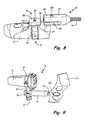
- FIG. 4is a perspective view of the universal mounting member clamped to the camera.
- FIG. 5is a perspective view of a gun barrel mount and a thumb screw from the mounting system.
- FIG. 6is an end view of the gun barrel mount.
- FIG. 7is an enlarged perspective view of the gun barrel mount attaching the camera to the gun barrel.
- FIG. 8is a perspective view of a bow mount and the universal mounting member clamped to the camera.
- FIG. 9is an enlarged side view of the bow mount attaching the camera to the bow.
- FIG. 10is a perspective view of a scope mount from the mounting system.
- FIG. 11is an enlarged perspective view of the scope mount attaching the camera to the scope on the gun.
- FIG. 12is a side view of an alternative embodiment of the universal mounting member.
- FIG. 13is a side view of a bipod coupled with the gun barrel mount.
- FIG. 14is a side view of a mounting bracket from the bipod.
- FIG. 1Ais a perspective view of camera 10 mounted to barrel 12 of shotgun 14 by universal mounting member 16 and gun barrel mount 18 of mounting system 20 .
- FIG. 1Bis a side view of camera 10 mounted to bow 22 by universal mounting member 16 and bow mount 24 of mounting system 20 .
- FIG. 1Cis a perspective view of camera 10 mounted to scope 26 on rifle 28 by universal mounting member 16 and scope mount 30 of mounting system 20 .
- FIG. 1Dis a perspective view of camera 10 mounted to scope 26 on crossbow 32 by universal mounting member 16 and scope mount 30 of mounting system 20 .
- the combination of universal mounting member 16 and one of gun barrel mount 18 , bow mount 24 , and scope mount 30provides a system for mounting camera 10 onto a plurality of weapons such as shotgun 14 , bow 22 , rifle 28 , and crossbow 32 .
- Universal mounting member 16attaches camera 10 , or any other hunting accessory (e.g. rangefinder, game caller, flashlight, laser pointer), to each of gun barrel mount 18 , bow mount 24 , and scope mount 30 .
- the “universality” of universal mounting member 16stems from its ability to remain attached to camera 10 and couple with each of gun barrel mount 18 , bow mount 24 , and scope mount 30 . Accordingly, mounting system 20 can reduce the amount of equipment carried by a game hunter to attach an accessory to a plurality of hunting weapons.
- universal mounting member 16is attached to camera 10 and coupled with another component of mounting system 20 in order to mount camera 10 onto a hunting weapon.
- universal mounting member 16is coupled to gun barrel mount 18 . Since gun barrel mount 18 is secured to barrel 12 of shotgun 14 , the coupling of universal mounting member 16 and gun barrel mount 18 mounts camera 10 onto shotgun 14 .
- Universal mounting member 16 and gun barrel mount 18are designed such that camera 10 is positioned downwardly and laterally from the attachment to barrel 12 and does not interfere with use of shotgun 14 .
- universal mounting member 16is coupled to bow mount 24 . Since bow mount 24 is secured to bow 22 , the coupling of universal mounting member 16 and gun bow mount 24 mounts camera 10 onto bow 22 . Mounting member 16 and bow mount 24 are designed such that camera 10 is positioned outwardly in front of bow and does not interfere with use of bow 22 .
- universal mounting member 16is coupled to scope mount 30 . Since scope mount 30 is secured to scope 26 , which is secured to rifle 28 , the coupling of universal mounting member 16 and scope mount 30 mounts camera 10 onto rifle 28 . Mounting member 16 and scope mount 30 are designed such that camera 10 is positioned downwardly and laterally from scope 26 alongside rifle 28 and does not interfere with use of scope 26 or rifle 28 .
- universal mounting member 16is coupled to scope mount 30 . Since scope mount 30 is secured to scope 26 , which is secured to crossbow 32 , the coupling of universal mounting member 16 and scope mount 30 mounts camera 10 onto crossbow. Mounting member 16 and scope mount 30 are designed such that camera 10 is positioned downwardly and laterally from scope 26 alongside crossbow 32 and does not interfere with use of scope 26 or crossbow 32 .
- FIG. 2is a perspective view of the components of mounting system 20 : universal mounting member 16 , gun barrel mount 18 , bow mount 24 , scope mount 30 , and thumb screw 33 .
- Universal mounting member 16includes first clamp 34 and rail mount or head 36 .
- Gun barrel mount 18includes first rail receiving track or first track 38 and second clamp 40 .
- Bow mount 24includes second rail receiving track or second track 42 and threaded attaching member 44 .
- Scope mount 30includes third rail receiving track or third track 46 and third clamp 48 .
- Head 36is received into one of first track 38 , second track 42 , and third track 46 to couple universal mounting member 16 with one of gun barrel mount 18 , bow mount 24 , and scope mount 30 .
- Universal mounting member 16includes a first end having first clamp 34 and an opposite, second end having head 36 .
- First clamp 34is substantially circular and configured to clamp onto and surround camera 10 . In alternative embodiments, first clamp 34 adopts other shapes to securely clamp onto non-circular cameras or other hunting accessories (e.g. rangefinder, game caller, flashlight).
- Head 36protrudes from first clamp 34 for coupling with gun barrel mount 18 , bow mount 24 , and scope mount 30 . Extending downwardly into head 36 is a threaded hole for receiving thumb screw 33 .
- first track 38 , second track 42 , and third track 46Located at first ends of each of gun barrel mount 18 , bow mount 24 , and scope mount 30 are first track 38 , second track 42 , and third track 46 , respectively.
- Each track 38 , 42 , 46is shaped for receiving head 36 and includes a central hole for receiving thumb screw 33 .
- the threaded hole in head 36is aligned with the hole in one of tracks 38 , 42 , 46 . Insertion of thumb screw 33 through the aligned holes secures the mated components and removes the “play” or tolerance between the mated components.
- Second end of gun barrel mount 18includes second clamp 40 for clamping barrel mount 18 onto gun barrel 12 (shown in FIG. 1A ).
- Second end of bow mount 24includes threaded attaching member 44 for insertion into a threaded aperture on bow 22 (shown in FIG. 1B ).
- Second end of scope mount 30includes third clamp 48 for clamping scope mount 30 onto scope 26 , which can be mounted to a number of different weapons (e.g. shotgun 28 shown in FIG. 1C and crossbow 32 shown in 1 D).
- Coupling universal mounting member 16 with one of gun barrel mount 18 , bow mount 24 , and scope mount 30allows a hunter to easily attach an accessory to a plurality of weapons.
- FIGS. 3 and 4are perspective views of a first embodiment of universal mounting member 16 from mounting system 20 .
- Universal mounting member 16includes first clamp 34 , head 36 , neck 50 , holes 51 , and threaded holes 52 .
- First clamp 34has yoke 54 and strap 56 .
- Yoke 54includes holes 51
- strap 56includes threaded holes 52 , for receiving screws 57 .
- Head 36includes top 58 , sides 60 , edges 62 , and bottom 64 .
- first clamp 34attaches universal mounting member 16 onto camera 10 and head 36 couples universal mounting member 16 with a track (e.g. first track 38 , second track 42 , or third track 46 ) on a weapon mount (e.g. gun barrel mount 18 , bow mount 24 , or scope mount 30 ).
- a tracke.g. first track 38 , second track 42 , or third track 46
- weapon mounte.g. gun barrel mount 18 , bow mount 24 , or scope mount 30 .
- Semi-circular yoke 54 and semi-circular strap 56join together to form substantially circular first clamp 34 .
- the flat open ends of yoke 54each include hole 51 and the flat open ends of strap each include threaded hole 52 .
- flat open ends of yoke 54are placed above and abut flat open ends of strap 56 .
- Each screw 57extends first through hole 51 in yoke 54 and second through threaded hole 52 in strap 56 . Screws 57 secure yoke 54 to strap 56 and allow first clamp 34 to exert compressive inward force around camera 10 , as shown in FIG. 4 .
- Non-circular cameras or different accessoriesmay necessitate a different shape for first clamp 34 . Different shapes are possible so long as first clamp 34 follows the contours of the accessory and is configured to exert an inwardly clamping force to the accessory.
- Head 36protrudes from a top, central point on yoke 54 . Extending between and attaching head 36 to yoke 54 is neck 50 . In the depicted embodiment, neck 50 is a short rectangular connection, but in other embodiments for other cameras 10 and accessories neck 50 is elongated to place more distance between yoke 54 and head 36 (e.g. see FIG. 7 ). When viewed together, head 36 and neck 50 form a T-shape. Head 36 includes flat top 58 , angled sides 60 each having bottom edge 62 , and flat bottom 64 . Top 58 and bottom 64 are parallel to one another and angled sides 60 including edges 62 extend between and connect top 58 to bottom 64 .
- FIG. 4head 36 is clamped to and extending from a top of camera 10 when in use. Once secured to camera 10 , head 36 is ready to couple with a track (e.g. first track 38 , second track 42 , or third track 46 ) on a weapon mount (e.g. gun barrel mount 18 , bow mount 24 , or scope mount 30 ).
- a tracke.g. first track 38 , second track 42 , or third track 46
- a weapon mounte.g. gun barrel mount 18 , bow mount 24 , or scope mount 30 .
- head 36is a male mounting member and is configured to mate with a plurality of female receiving tracks 38 , 40 , 46 .
- the male-female mating relationshipis reversed such that head 36 is replaced by a female receiving track and female receiving tracks 38 , 40 , 46 are replaced by male heads.
- FIGS. 5 , 6 , and 7depict gun barrel mount 18 from mounting system 20 .
- FIG. 5is a perspective view of gun barrel mount 18 and thumb screw 33
- FIG. 6is an end view of gun barrel mount 18
- FIG. 7is an enlarged perspective view of gun barrel mount 18 attaching camera 10 to barrel 12 of shotgun 14 .
- Gun barrel mount 18includes first track 38 at a first end and second clamp 40 at a second end.
- First track 38includes top 66 , sides 68 , bottom 70 , slot 72 , and hole 74 .
- Second clamp 40includes yoke 76 , strap 78 , opening 80 , gap 82 , and screw holes 84 for receiving screws 86 .
- Thumb screw 33includes threaded member 88 , stop 90 , and screw head 92 .
- Thumb screw 33secures head 36 inside of first track 38
- second clamp 40secures gun barrel mount 18 to barrel 12 of shotgun 14 .
- First track 38is formed by flat top 66 , flat bottom 70 , and angled sides 68 extending between and connecting top 66 to bottom 70 .
- Top 66 and bottom 70are substantially parallel to one another.
- Sides 68form an obtuse angle with top 66 and extend downwardly and outwardly to flat edges, which form an approximately right angle with bottom 70 .
- Bottom 70is not closed and includes central slot 72 for accommodating neck 50 .
- First track 38is configured to receive and couple with head 36 as shown in FIG. 7 .
- Top 58 of head 36slides in beneath and parallel to top 66 of first track 38 .
- Sides 60 of head 36slide in next to and share approximately the same angle as sides 68 of first track 38 .
- Bottom 64 of head 36slides in above and parallel with bottom of 70 of first track 38 .
- Neck 50 of head 36extends through slot 72 of first track 38 , such that universal mounting member 16 depends downwardly from first track 38 of gun barrel mount 18 .
- Second clamp 40is substantially circular and formed by semi-circular yoke 76 and semi-circular strap 78 .
- Yoke 76extends laterally from first track 38 such that bottom 70 of rail receiving track 38 is substantially parallel with a bottom of yoke 76 .
- a top of yoke 76extends upwardly and forms an angular sloped surface with top 66 of first track 38 .
- Strap 78is a mirror image of yoke 76 . When the flat bottoms of yoke 76 and strap 78 are aligned they abut and a circular space 80 is formed therebetween.
- gun barrel mount 18Use of gun barrel mount 18 is shown in FIG. 7 .
- Second clamp 44substantially surrounds barrel 12 of shotgun 14 and head 36 is secured in first track 38 by thumb screw 33 .
- Gun barrel mount 18extends substantially laterally from barrel 12 and universal mounting member 16 extends substantially vertically from gun barrel mount 18 such that camera 10 is located to the side and slightly below barrel 12 of shotgun 14 .
- Gun barrel mount 18is ambidextrous and can be positioned either to the right or to the left of barrel 12 . So positioned, operation of camera 10 is handy for a hunter and will not interfere with use of shotgun 14 .
- FIG. 8is a perspective view of bow mount 24 coupling with universal mounting member 16 attached to camera 10
- FIG. 9is an enlarged side view of bow mount 24 attaching universal mounting member 16 , and therefore camera 10 , to bow 22
- universal mounting member 16includes first clamp 34 and head 36 .
- Head 36further includes threaded hole 52 , top 58 , sides 60 , and bottom 64 .
- Bow mount 24includes threaded attaching member 44 and second track 42 .
- Second track 42further includes top 94 , bottom 96 , slot 98 , and hole 100 .
- Second track 42 of bow mount 24receives head 36 of universal mounting member 16 to attach camera 10 to bow 22 .
- a first end of bow mount 24has second track 42 .
- a second, opposite end of bow mount 24has threaded attaching member 44 .
- Second track 42is elongated and extends laterally from threaded attaching member 44 .
- Second track 42is defined by top 94 , bottom 96 , and slot 98 .
- Top 94 and bottom 96are substantially parallel to one another.
- Bottom 96is split into two pieces by slot 98 to accommodate neck 50 .
- Extending into second track 42 between top 94 and bottom 96is an elongated opening for receiving head 36 .
- Top 58 of head 36is received into second track 42 and positioned beneath top 94 .
- Sides 60 of head 36are received into second track 42 and reside in a space located between top 94 and bottom 96 .
- Bottom 64 of head 36is received into second track 42 and positioned above bottom 96 .
- Neck 50extends downwardly from head 36 through slot 98 of second track 42 .
- hole 100 of bow mount 24is aligned above threaded hole 52 of universal mounting member 16 .
- Thumb screw 33can then be inserted through hole 100 into threaded hole 52 to secure head 36 within second track 42 and remove the tolerance from the mated coupling (i.e. align camera 10 with bow mount 24 ).
- FIG. 9depicts the attachment of camera 10 to bow 22 through bow mount 24 and universal mounting member 16 .
- Threaded attaching member 44 of bow mount 24is inserted and screwed into threaded aperture 102 located on front of bow 22 for a stabilizing bar.
- Second track 42extends outwardly in front of bow 22 to couple with head 36 .
- head 36is attached to a bottom of camera 10 such that neck 50 projects camera 10 upwardly above second track 42 . If head 36 extends from a top of camera 10 (as shown in FIG. 8 ), then camera 10 will depend downwardly below second track 42 .
- camera 10is located out in front of bow 22 such that operation of camera 10 is handy, but will not interfere with use of bow 22 .
- FIG. 10is a perspective view of scope mount 30 from mounting system 20
- FIG. 11is an enlarged perspective view of scope mount 30 and thumb screw 33 attaching the camera 10 to scope 26 on rifle 28
- Scope mount 30includes third track 46 at a first end and third clamp 48 and a second end.
- Third track 46includes top 104 , sides 106 , bottom 108 , slot 110 , and hole 112 .
- Third clamp 48includes yoke 114 , strap 116 , and opening 118 .
- Yoke 114includes near side 120 and far side 122 .
- Strap 116includes near side 124 and far side 126 .
- Holes 128 and screws 130extend through strap 116 and yoke 114 to secure third clamp 48 around scope 26 , which can be attached to a weapon such as rifle 28 or cross bow 32 .
- Third track 46is similar to first track 38 described above with respect to FIG. 5 .
- Third track 46is defined by flat top 104 , flat bottom 108 , and angled sides 106 extending between and connecting top 104 to bottom 108 .
- Top 104 and bottom 108are substantially parallel to one another.
- Sides 106form an obtuse angle with top 104 and extend downwardly and outwardly to flat edges, which form an approximately right angle with bottom 108 . Ends of bottom 108 are not joined and form slot 110 .
- Third track 46is configured to receive and couple with head 36 and neck 50 extends through slot 110 as shown in FIG. 10 .
- Top 58 of head 36slides in beneath and parallel to top 104 of third track 46 .
- Third clamp 48is similar to first clamp 34 described above with respect to FIG. 3 .
- Third clamp 48is substantially circular and formed by semi-circular yoke 114 and semi-circular strap 116 .
- Yoke 114is attached to and extends laterally from third track 46 such that bottom 108 of third track 46 is substantially parallel with a bottom of yoke 114 . Ends of both yoke 114 and strap 116 are flat such that yoke 114 and upper clamp 114 can be secured to form central circular space 118 .
- near end 120 of yoke 114abuts near end 124 of strap 116 and far end 122 of yoke 114 abuts far end 126 of strap 116 .
- Ends of yoke 114 and strap 116are flared to allow space for two screw holes 128 extending therethrough.
- Screws 130are inserted through holes 128 on near side 124 of strap 116 and into threaded holes 128 on near side 120 of yoke 114 to secure strap 116 to yoke 114 .
- screws 130are inserted through holes 128 on far side 126 of strap 116 and into threaded holes 128 on far side 122 of yoke 114 to secure strap 116 to yoke 114 .
- scope mount 30Use of scope mount 30 is shown in FIG. 11 .
- Third clamp 48surrounds scope 26 mounted on rifle 28 and head 36 is secured in third track 46 by thumb screw 33 .
- Scope 26can alternatively be mounted to another weapon, such as crossbow 32 shown in FIG. 1D .
- Scope mount 30extends substantially laterally from scope 26 and universal mounting member 16 extends substantially downwardly from scope mount 30 such that camera 10 is located to the along side shotgun 28 (or crossbow 32 ) and below scope 26 .
- Scope mount 30is ambidextrous such that it can extend to either the right or the left of scope 26 . So positioned, operation of camera 10 is handy for a hunter and will not interfere with use of rifle 28 (or crossbow 32 ).
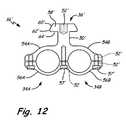
- FIG. 12is a side view of an alternative embodiment of universal mounting member 16 ′ for mounting two accessories side-by-side.
- Universal mounting member 16 ′includes left clamp 34 A, right clamp 34 B, head 36 ′, neck 50 ′, and threaded hole 52 ′.
- Left clamp 34 Aincludes yoke 54 A and strap 56 A
- right clamp 34 Bincludes yoke 54 B and strap 56 B.
- Upper clamps 54 A, 54 B and lower clamps 56 A, 56 Binclude holes 52 ′ for receiving screws 57 ′.
- Head 36 ′includes top 58 ′, sides 60 ′, edges 62 ′, and bottom 64 ′.
- Left clamp 34 A and right clamp 34 Battach universal mounting member 16 ′ onto two accessories and head 36 ′ couples with a track (e.g. first track 38 , second track 42 , or third track 46 ) on a weapon mount (e.g. gun barrel mount 18 , bow mount 24 , or scope mount 30 ).
- a tracke.g. first
- Universal mounting member 16 ′is substantially similar to universal mounting member 16 described above with reference to FIGS. 3-4 and like reference numerals designate like components. Instead of forming a single circular clamp (see first clamp 34 in FIGS. 3-4 ), universal mounting member 16 ′ includes two side-by-side circular clamps: left clamp 34 A and right clamp 34 B. Yoke 54 ′ includes left semi-circle 54 A and right semi-circle 54 B. Similarly, strap 56 ′ includes left semi-circle 56 A and right semi-circle 56 B. When flat open ends and centers of yoke 54 A, 54 B and strap 56 A, 56 B are joined, two substantially circular side-by-side clamps 34 A, 34 B are formed.
- holes 52 ′for receiving screws 57 ′.
- Screws 57 ′secure yoke 54 A, 54 B to strap 56 A, 56 B and allow left clamp 54 A and right clamp 56 A to exert compressive inward force around two circular accessories, such as a flashlight and a laser pointer.
- left clamp 54 Ais located above right clamp 56 A such that two accessories can be mounted vertically with one accessory being located on top of the other accessory.
- head 36 ′will not be described in detail as head 36 ′ is substantially similar to head 36 described above with reference to FIGS. 3 and 4 .
- Head 36 ′is coupled to a weapon mount in order to mount two accessories to a weapon. As shown above with respect to head 36 , head 36 ′ is receivable into first track 38 of gun barrel mount 18 ( FIGS. 5-7 ), second track 42 of bow mount 24 ( FIGS. 8-9 ) and third track 46 scope mount 30 ( FIGS. 10-11 ).
- Neck 50 ′extends downwardly from head 36 ′ and is accommodated by slots 72 , 98 , 100 as described above for Neck 50 .
- Universal mounting member 16 ′provides further flexibility to mounting kit 20 by providing left clamp 34 A and right clamp 34 B that can mount two accessories simultaneously to any one of the weapon mounts.
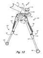
- FIG. 13is a side view of bipod 132 coupled with gun barrel mount 18 , which is clamped onto gun barrel 12 .
- gun barrel mount 18includes first track 38 and first clamp 40 .
- Bipod 132includes two legs 134 , support 136 , bipod mount 138 , and screw 139 .
- Legs 134each include foot 140 , telescoping portion 142 , lock 144 , and spring 146 .
- Thumb screw 33secures bipod mount 138 within gun barrel mount 18 , such that gun barrel 12 is supported above the ground by bipod 132 .
- Bipod 132is additional accessory that couples with gun barrel mount 18 of mounting kit 20 .
- second clamp 40surrounds gun barrel 12 and first track 38 extends laterally from second clamp 40 .
- bipod 132is coupled to first track 38 of gun barrel mount 18 .
- Legs 134 of bipodextend vertically upwards and toward one another to attach with central support 136 .
- bipod mount 138Located on a top on support 136 is bipod mount 138 (shown and described in detail below with respect to FIG. 14 ).
- Bipod mount 138is attached to support 136 by screw 139 and is configured to couple with first track 38 of gun barrel mount 18 .
- the bottom of each leg 134has enlarged foot 140 for contacting the ground.
- each leg 134has telescoping portion 142 securable by lock 144 such that the overall length of legs 134 is adjustable.
- Springs 146extend between a mid portion of legs 134 and support 136 for providing tension therebetween.
- legs 134are extended to a desired length and secured at the desired length by lock 144 .
- Bipod mount 138is coupled with gun barrel mount 18 , and the coupling is secured by insertion of thumb screw 33 . Once bipod mount 138 and gun barrel mount 18 are coupled and secured, legs 134 of bipod 132 support gun barrel 12 above the ground for hands-free use by a hunter.
- FIG. 14is a side view of bipod mount 138 from bipod 132 .
- Bipod mount 138has first end 148 , second end 150 , and arm 152 extending between first end 148 and second end 150 .
- First end 148includes head 36 ′′, neck 50 ′′, hole 52 ′′, top 58 ′′, sides 60 ′′, corners 62 ′′, and bottom 64 ′′.
- Second end 150includes vertical spacer 154 and screw hole 156 .
- Screw 139(shown in FIG. 13 ) extends through screw hole 156 to couple bipod mount 138 to bipod 132 , and head 36 ′′ couples with gun barrel mount 18 to attach bipod 132 to gun barrel 12 .
- First end 148 of bipod mount 138includes head 36 ′′, which is substantially similar to head 36 ′ (described above with reference to FIG. 12 ) and head 36 (described above with reference to FIGS. 3-4 ).
- Head 36 ′′is receivable into first track 38 of gun barrel mount 18 as shown in FIG. 13 .
- Thumb screw 33is inserted into hole 50 ′′ to secure the connection between head 36 ′′ and first track 38 of gun barrel mount 18 and remove any tolerance therebetween.
- second end 150is attached to first end 148 by laterally extending arm 152 .
- Second end 150includes vertical spacer 154 attached on top of screw hole 156 .
- Vertical spacer 154is configured to extend slightly above support 136 of bipod 132 and provide vertical clearance for laterally extending arm 152 .
- Screw hole 156is aligned with a screw hole on support 136 and is configured to receive screw 139 (shown in FIG. 13 ) thereby attaching second end 150 of bipod mount 138 to bipod 132 .
Landscapes
- Engineering & Computer Science (AREA)
- General Engineering & Computer Science (AREA)
- Mechanical Engineering (AREA)
- Aiming, Guidance, Guns With A Light Source, Armor, Camouflage, And Targets (AREA)
Abstract
Description
The present disclosure relates generally to hunting weapons and more particularly to a system for mounting accessories onto hunting weapons.
Game hunters desire to attach accessories to their hunting weapons in a manner that does not impede their ability to hunt. Several mounting systems exist for attaching a specific accessory to a specific weapon. Any given hunter, however, may have a plurality of accessories such as rangefinders, cameras, and scopes. The same hunter may also have a plurality of weapons such as rifles, shotguns, bows, and crossbows. Each accessory and weapon combination necessitates a specific mounting system designed for attaching that accessory that weapon. Thus, the hunter is forced to either carry all possible combinations of accessories and weapons or leave some accessories and weapons at home.
A system for mounting an accessory to more than one weapon is disclosed. The system includes a universal mounting member, a first mount, a second mount, and a screw. The universal mounting member includes a head attached to a first clamp. The head has a threaded hole and the first clamp is configured to surround the accessory. The first mount includes a first track attached to a second clamp. The first track receives the head and the second clamp attaches the first mount to a first weapon. The second mount includes a second track attached to a means for mounting to a second weapon. The second track receives the head and the second weapon is of a different kind than the first weapon. The screw is inserted through a hole located in one of the first track or the second track and into the threaded hole on the head. The screw secures a coupling between the head of universal mounting member and the first track of the first mount or the second track of the second mount.
A system for mounting an accessory to a scope, a gun barrel, and a bow is also disclosed. The system includes a universal mounting member, a scope mount, a gun barrel mount, a bow mount, and a screw. The universal mounting member includes a head attached to a first clamp by a neck. The head has a threaded hole and the first clamp is configured to surround the accessory. The scope mount includes a first track, a first slot, and a second clamp. The first track receives the head, the first slot accommodates the neck, and the second clamp attaches the scope mount to the scope. The gun barrel mount includes a second track, a second slot, and a third clamp. The second track receives the head, the second slot accommodates the neck, and the third clamp attaches the gun barrel mount to the gun barrel. The bow mount includes a third track, a third slot, and a threaded attaching member. The third track receives the head, the third slot accommodates the neck, and the threaded attaching member attaches the bow mount to the bow. The screw is inserted through a hole located in one of the first track, the second track, or the third track and into the threaded hole on the head. The screw secures a coupling between the head of universal mounting member and the first track of the scope mount, the second track of the gun barrel mount, or the third track of the bow mount in order to mount the accessory to the scope, the gun barrel, and the bow, respectively.
A method for mounting an electrical device to a plurality of weapons is also disclosed. The method includes attaching a universal mounting member having a head to the electrical device and inserting the head into a first track of a first weapon mount to from a first mated coupling. The method further includes inserting a screw through the first track and into the head to secure the mated coupling.
The combination of universal mountingmember 16 and one ofgun barrel mount 18,bow mount 24, and scope mount30 provides a system for mountingcamera 10 onto a plurality of weapons such asshotgun 14,bow 22,rifle 28, andcrossbow 32. Universal mountingmember 16 attachescamera 10, or any other hunting accessory (e.g. rangefinder, game caller, flashlight, laser pointer), to each ofgun barrel mount 18,bow mount 24, andscope mount 30. The “universality” of universal mountingmember 16 stems from its ability to remain attached tocamera 10 and couple with each ofgun barrel mount 18,bow mount 24, andscope mount 30. Accordingly, mountingsystem 20 can reduce the amount of equipment carried by a game hunter to attach an accessory to a plurality of hunting weapons.
In each ofFIGS. 1A-1C , universal mountingmember 16 is attached tocamera 10 and coupled with another component of mountingsystem 20 in order to mountcamera 10 onto a hunting weapon. InFIG. 1A , universal mountingmember 16 is coupled togun barrel mount 18. Since gun barrel mount18 is secured tobarrel 12 ofshotgun 14, the coupling of universal mountingmember 16 and gun barrel mount18mounts camera 10 ontoshotgun 14. Universal mountingmember 16 and gun barrel mount18 are designed such thatcamera 10 is positioned downwardly and laterally from the attachment tobarrel 12 and does not interfere with use ofshotgun 14.
InFIG. 1B , universal mountingmember 16 is coupled to bowmount 24. Since bow mount24 is secured to bow22, the coupling of universal mountingmember 16 and gun bow mount24mounts camera 10 ontobow 22. Mountingmember 16 and bowmount 24 are designed such thatcamera 10 is positioned outwardly in front of bow and does not interfere with use ofbow 22.
InFIG. 1C , universal mountingmember 16 is coupled toscope mount 30. Sincescope mount 30 is secured toscope 26, which is secured to rifle28, the coupling of universal mountingmember 16 and scope mount30mounts camera 10 ontorifle 28. Mountingmember 16 and scope mount30 are designed such thatcamera 10 is positioned downwardly and laterally fromscope 26 alongsiderifle 28 and does not interfere with use ofscope 26 orrifle 28.
InFIG. 1D , universal mountingmember 16 is coupled toscope mount 30. Sincescope mount 30 is secured toscope 26, which is secured tocrossbow 32, the coupling of universal mountingmember 16 and scope mount30mounts camera 10 onto crossbow. Mountingmember 16 and scope mount30 are designed such thatcamera 10 is positioned downwardly and laterally fromscope 26 alongsidecrossbow 32 and does not interfere with use ofscope 26 orcrossbow 32.
Universal mountingmember 16 includes a first end havingfirst clamp 34 and an opposite, secondend having head 36.First clamp 34 is substantially circular and configured to clamp onto andsurround camera 10. In alternative embodiments,first clamp 34 adopts other shapes to securely clamp onto non-circular cameras or other hunting accessories (e.g. rangefinder, game caller, flashlight).Head 36 protrudes fromfirst clamp 34 for coupling withgun barrel mount 18,bow mount 24, andscope mount 30. Extending downwardly intohead 36 is a threaded hole for receivingthumb screw 33.
Located at first ends of each ofgun barrel mount 18,bow mount 24, and scope mount30 arefirst track 38,second track 42, andthird track 46, respectively. Eachtrack head 36 and includes a central hole for receivingthumb screw 33. Oncehead 36 is received into and coupled with one offirst track 38,second track 42, andthird tack 46, the threaded hole inhead 36 is aligned with the hole in one oftracks thumb screw 33 through the aligned holes secures the mated components and removes the “play” or tolerance between the mated components.
Located at second ends of each ofgun barrel mount 18,bow mount 24, and scope mount30 are means for securing the mount to a particular weapon or weapon accessory. Second end of gun barrel mount18 includessecond clamp 40 for clampingbarrel mount 18 onto gun barrel12 (shown inFIG. 1A ). Second end ofbow mount 24 includes threaded attachingmember 44 for insertion into a threaded aperture on bow22 (shown inFIG. 1B ). Second end ofscope mount 30 includesthird clamp 48 for clampingscope mount 30 ontoscope 26, which can be mounted to a number of different weapons (e.g.shotgun 28 shown inFIG. 1C andcrossbow 32 shown in1D). Coupling universal mountingmember 16 with one ofgun barrel mount 18,bow mount 24, and scope mount30 allows a hunter to easily attach an accessory to a plurality of weapons.
At a first end of gun barrel mount18 isfirst track 38.First track 38 is formed by flat top66, flat bottom70, and angledsides 68 extending between and connecting top66 tobottom 70.Top 66 and bottom70 are substantially parallel to one another.Sides 68 form an obtuse angle with top66 and extend downwardly and outwardly to flat edges, which form an approximately right angle with bottom70.Bottom 70 is not closed and includescentral slot 72 for accommodatingneck 50.First track 38 is configured to receive and couple withhead 36 as shown inFIG. 7 .Top 58 ofhead 36 slides in beneath and parallel to top66 offirst track 38.Sides 60 ofhead 36 slide in next to and share approximately the same angle assides 68 offirst track 38.Bottom 64 ofhead 36 slides in above and parallel with bottom of70 offirst track 38.Neck 50 ofhead 36 extends throughslot 72 offirst track 38, such that universal mountingmember 16 depends downwardly fromfirst track 38 ofgun barrel mount 18.
At a second, opposite end of gun barrel mount18 issecond clamp 40.Second clamp 40 is substantially circular and formed bysemi-circular yoke 76 andsemi-circular strap 78.Yoke 76 extends laterally fromfirst track 38 such thatbottom 70 ofrail receiving track 38 is substantially parallel with a bottom ofyoke 76. A top ofyoke 76 extends upwardly and forms an angular sloped surface withtop 66 offirst track 38.Strap 78 is a mirror image ofyoke 76. When the flat bottoms ofyoke 76 andstrap 78 are aligned they abut and acircular space 80 is formed therebetween. When the tops ofyoke 76 andstrap 78 are aligned they leavegap 82. Extending through bottom ofstrap 78 and into bottom nearclamp 78 are threadedholes 84. As shown inFIGS. 5 and 6 , a plurality ofscrews 86 are inserted into threadedholes 84 to join the bottom ofstrap 78 to thebottom yoke 76. Whenyoke 76 andstrap 78 are joined aroundbarrel 12 ofshotgun 14, screws86 are tightened so thatsecond clamp 40 exerts compressive force ontobarrel 12 as shown inFIG. 7 .
In order to inserthead 36 intofirst track 38, some tolerance is required between the mating components. Afterhead 36 is received intofirst track 38,hole 74 offirst track 38 is aligned above threadedhole 52 ofhead 36. Threadedmember 88 ofthumb screw 33 is then inserted throughhole 74 offirst track 38 and engages with the internal threads of threadedhole 52 inhead 36.Thumb screw 33 is further screwed into threadedhole 52 ofhead 36 by rotation ofenlarged screw head 92 untilstop 90 contacts top66 offirst track 38. The engagement ofthumb screw 33 pullshead 36 upwardly inrail receiving track 38 and removes the tolerance betweentop 58 ofhead 36 and top66 offirst track 38. The tolerance is also removed betweensides 60 ofhead 36 andsides 68 offirst track 38 such thathead 36 andfirst track 38 are securely coupled and aligned with one another.
Use of gun barrel mount18 is shown inFIG. 7 .Second clamp 44 substantially surroundsbarrel 12 ofshotgun 14 andhead 36 is secured infirst track 38 bythumb screw 33. Gun barrel mount18 extends substantially laterally frombarrel 12 and universal mountingmember 16 extends substantially vertically from gun barrel mount18 such thatcamera 10 is located to the side and slightly belowbarrel 12 ofshotgun 14. Gun barrel mount18 is ambidextrous and can be positioned either to the right or to the left ofbarrel 12. So positioned, operation ofcamera 10 is handy for a hunter and will not interfere with use ofshotgun 14.
A first end ofbow mount 24 hassecond track 42. A second, opposite end ofbow mount 24 has threaded attachingmember 44.Second track 42 is elongated and extends laterally from threaded attachingmember 44.Second track 42 is defined by top94, bottom96, andslot 98.Top 94 and bottom96 are substantially parallel to one another.Bottom 96 is split into two pieces byslot 98 to accommodateneck 50. Extending intosecond track 42 betweentop 94 and bottom96 is an elongated opening for receivinghead 36.Top 58 ofhead 36 is received intosecond track 42 and positioned beneathtop 94.Sides 60 ofhead 36 are received intosecond track 42 and reside in a space located between top94 and bottom96.Bottom 64 ofhead 36 is received intosecond track 42 and positioned abovebottom 96.Neck 50 extends downwardly fromhead 36 throughslot 98 ofsecond track 42. Oncehead 36 is received into secondrail receiving member 42,hole 100 ofbow mount 24 is aligned above threadedhole 52 of universal mountingmember 16.Thumb screw 33 can then be inserted throughhole 100 into threadedhole 52 to securehead 36 withinsecond track 42 and remove the tolerance from the mated coupling (i.e.align camera 10 with bow mount24).
At a first end ofscope mount 30 isthird track 46.Third track 46 is similar tofirst track 38 described above with respect toFIG. 5 .Third track 46 is defined byflat top 104,flat bottom 108, and angledsides 106 extending between and connecting top104 tobottom 108. Top104 and bottom108 are substantially parallel to one another.Sides 106 form an obtuse angle with top104 and extend downwardly and outwardly to flat edges, which form an approximately right angle withbottom 108. Ends ofbottom 108 are not joined andform slot 110.Third track 46 is configured to receive and couple withhead 36 andneck 50 extends throughslot 110 as shown inFIG. 10 .Top 58 ofhead 36 slides in beneath and parallel to top104 ofthird track 46.Sides 60 ofhead 36 slide in next to and share approximately the same angle assides 106 ofthird track 46.Bottom 64 ofhead 36 slides in above and parallel with bottom of108 ofthird track 46.Neck 50 extends throughslot 110 ofthird track 46, such that universal mountingmember 16 depends downwardly fromthird track 46 ofscope mount 30.
At a second, opposite end ofscope mount 30 isthird clamp 48.Third clamp 48 is similar tofirst clamp 34 described above with respect toFIG. 3 .Third clamp 48 is substantially circular and formed bysemi-circular yoke 114 andsemi-circular strap 116.Yoke 114 is attached to and extends laterally fromthird track 46 such thatbottom 108 ofthird track 46 is substantially parallel with a bottom ofyoke 114. Ends of bothyoke 114 andstrap 116 are flat such thatyoke 114 andupper clamp 114 can be secured to form centralcircular space 118. More specifically, nearend 120 ofyoke 114 abuts nearend 124 ofstrap 116 andfar end 122 ofyoke 114 abutsfar end 126 ofstrap 116. Ends ofyoke 114 andstrap 116 are flared to allow space for twoscrew holes 128 extending therethrough.Screws 130 are inserted throughholes 128 onnear side 124 ofstrap 116 and into threadedholes 128 onnear side 120 ofyoke 114 to securestrap 116 toyoke 114. Similarly, screws130 are inserted throughholes 128 onfar side 126 ofstrap 116 and into threadedholes 128 onfar side 122 ofyoke 114 to securestrap 116 toyoke 114. Whenstrap 116 andyoke 114 are joined aroundscope 30,screws 130 are tightened so thatthird clamp 48 exerts compressive force ontoscope 30 as shown inFIG. 11 .
As explained above with respect toFIG. 7 , some tolerance is required between mating components for assembly and disassembly, but once components are mated the tolerance can be removed so that the accessory is consistently aligned. Afterhead 36 is received intothird track 46,hole 112 ofthird track 46 is aligned above threadedhole 52 ofhead 36. Threadedmember 88 ofthumb screw 33 is inserted throughhole 112 ofthird track 46 to engage internal threads of threadedhole 52 inhead 36.Thumb screw 33 is further screwed into threadedhole 52 ofhead 36 by rotation ofenlarged screw head 92 untilstop 90 contacts top104 ofthird track 46. Engagement ofthumb screw 33 pullshead 36 upwardly inrail receiving track 46 and removes the tolerance betweentop 58 ofhead 36 andtop 104 ofthird track 46. The tolerance is also removed betweensides 60 ofhead 36 andsides 106 ofthird track 46 such thathead 36 andthird track 46 are securely coupled to and aligned with one another.
Use ofscope mount 30 is shown inFIG. 11 .Third clamp 48 surroundsscope 26 mounted onrifle 28 andhead 36 is secured inthird track 46 bythumb screw 33.Scope 26 can alternatively be mounted to another weapon, such ascrossbow 32 shown inFIG. 1D .Scope mount 30 extends substantially laterally fromscope 26 and universal mountingmember 16 extends substantially downwardly fromscope mount 30 such thatcamera 10 is located to the along side shotgun28 (or crossbow32) and belowscope 26.Scope mount 30 is ambidextrous such that it can extend to either the right or the left ofscope 26. So positioned, operation ofcamera 10 is handy for a hunter and will not interfere with use of rifle28 (or crossbow32).
Universal mountingmember 16′ is substantially similar to universal mountingmember 16 described above with reference toFIGS. 3-4 and like reference numerals designate like components. Instead of forming a single circular clamp (seefirst clamp 34 inFIGS. 3-4 ), universal mountingmember 16′ includes two side-by-side circular clamps:left clamp 34A andright clamp 34B.Yoke 54′ includes left semi-circle54A and right semi-circle54B. Similarly,strap 56′ includes left semi-circle56A and right semi-circle56B. When flat open ends and centers ofyoke strap yoke strap screws 57′. When flat open ends and centers ofyoke strap left clamp 34A andright clamp 34B are formed.Screws 57′ extend firstly throughholes 52′ instrap holes 52′ inyoke Screws 57′secure yoke left clamp 54A andright clamp 56A to exert compressive inward force around two circular accessories, such as a flashlight and a laser pointer. In an alternative embodiment,left clamp 54A is located aboveright clamp 56A such that two accessories can be mounted vertically with one accessory being located on top of the other accessory.
For the sake of brevity,head 36′ will not be described in detail ashead 36′ is substantially similar tohead 36 described above with reference toFIGS. 3 and 4 .Head 36′ is coupled to a weapon mount in order to mount two accessories to a weapon. As shown above with respect tohead 36,head 36′ is receivable intofirst track 38 of gun barrel mount18 (FIGS. 5-7 ),second track 42 of bow mount24 (FIGS. 8-9 ) andthird track 46 scope mount30 (FIGS. 10-11 ).Neck 50′ extends downwardly fromhead 36′ and is accommodated byslots Neck 50. Just as withhead 36,thumb screw 33 is inserted to secure the connection between any given track andhead 36′ and remove any tolerance therebetween. Universal mountingmember 16′ provides further flexibility to mountingkit 20 by providingleft clamp 34A andright clamp 34B that can mount two accessories simultaneously to any one of the weapon mounts.
Although the present invention has been described with reference to preferred embodiments, workers skilled in the art will recognize that changes may be made in form and detail without departing from the spirit and scope of the invention.
Claims (18)
1. A system for mounting an accessory to more than one weapon, the system comprising:
a universal mounting member including a head attached to a first clamp, the head having a threaded hole and the first clamp configured to surround the accessory;
a first mount including a first track attached to a second clamp, the first track for receiving the head and the second clamp for attaching the first mount to a first weapon;
a second mount including a second track attached to a means for mounting to a second weapon, the second track for receiving the head and the second weapon being of a different kind than the first weapon; and
a screw for insertion through a hole located in one of the first track or the second track and into the threaded hole on the head, wherein the screw secures a coupling between the head of the universal mounting member and the first track of the first mount or the second track of the second mount.
2. The system ofclaim 1 , further comprising:
a third mount including a third track attached to a third clamp, the third track for receiving the head and the third clamp for attaching the third mount to a third weapon.
3. The system ofclaim 2 , wherein the third clamp attaches to a scope, the scope being mounted on the third weapon.
4. The system ofclaim 1 , wherein the head is attached to the first clamp by a neck.
5. The system ofclaim 4 , wherein the first mount includes a slot for accommodating the neck when the head is received into the first track.
6. A system for mounting an accessory to a scope, a gun barrel, and a bow, the system comprising:
a universal mounting member including a head attached to a first clamp by a neck, the head having a threaded hole and the first clamp configured to surround the accessory;
a scope mount including a first track, a first slot, and a second clamp, the first track for receiving the head, the first slot for accommodating the neck, and the second clamp for attaching the scope mount to the scope;
a gun barrel mount including a second track, a second slot, and a third clamp, the second track for receiving the head, the second slot for accommodating the neck, and the third clamp for attaching the scope mount to the scope;
a bow mount including a third track, a third slot, and a threaded attaching member, the third track for receiving the head, the third slot for accommodating the neck, and the threaded attaching member for attaching the bow mount to the bow; and
a screw for insertion through a hole located in one of the first track, the second track, or the third track and into the threaded hole on the head, wherein the screw secures a coupling between the head of universal mounting member and the first track of the scope mount, the second track of the gun barrel mount, or the third track of the bow mount in order to mount the accessory to the scope, the gun barrel, and the bow, respectively.
7. The system ofclaim 6 , wherein the head has a mating relationship with each of the first track, the second track, and the third track.
8. The system ofclaim 7 , wherein the neck extends through the first slot, the second slot, or the third slot when the head is mated with the first track, the second track, or the third track, respectively.
9. The system ofclaim 6 , wherein the scope is attached to one of a gun and a crossbow.
10. A method for mounting an electrical device to plurality of weapons, the method comprising:
attaching a universal mounting member having a head to the electrical device;
inserting the head into a first track of a first weapon mount to form a first mated coupling; inserting a screw through the first track and into the head to secure the mated coupling; and
clamping the first weapon mount to a first weapon.
11. The method ofclaim 10 , wherein inserting the screw through the first track and into the head removes tolerance from the mated coupling.
12. The method ofclaim 10 , further comprising:
accommodating a neck of the universal mounting member with a slot in the first weapon mount.
13. The method ofclaim 10 , wherein attaching the universal mounting member to the electrical device includes clamping the universal mounting member to the electronic device.
14. The method ofclaim 10 , further comprising:
removing the head from the first track of the first weapon mount;
inserting the head into a second track of a second weapon mount to form a second mated coupling; and
inserting the screw through the second track and into the head to secure the second mated coupling.
15. The method ofclaim 10 , wherein the first weapon mount is one of a scope mount, a gun barrel mount, and a bow mount.
16. The method ofclaim 15 , wherein clamping the first weapon mount to a first weapon further comprises:
clamping the gun barrel mount around the gun barrel.
17. The method ofclaim 15 , wherein clamping the first weapon mount to a first weapon further comprises:
clamping the scope mount around a scope.
18. The method ofclaim 17 , wherein the scope is mounted on a gun or a crossbow.
Priority Applications (2)
| Application Number | Priority Date | Filing Date | Title |
|---|---|---|---|
| US12/930,122US8656624B2 (en) | 2010-12-29 | 2010-12-29 | Universal device mount |
| US13/200,881US8656625B2 (en) | 2010-12-29 | 2011-10-04 | Accessory mount |
Applications Claiming Priority (1)
| Application Number | Priority Date | Filing Date | Title |
|---|---|---|---|
| US12/930,122US8656624B2 (en) | 2010-12-29 | 2010-12-29 | Universal device mount |
Related Child Applications (1)
| Application Number | Title | Priority Date | Filing Date |
|---|---|---|---|
| US13/200,881Continuation-In-PartUS8656625B2 (en) | 2010-12-29 | 2011-10-04 | Accessory mount |
Publications (2)
| Publication Number | Publication Date |
|---|---|
| US20120167441A1 US20120167441A1 (en) | 2012-07-05 |
| US8656624B2true US8656624B2 (en) | 2014-02-25 |
Family
ID=46379459
Family Applications (1)
| Application Number | Title | Priority Date | Filing Date |
|---|---|---|---|
| US12/930,122Expired - Fee RelatedUS8656624B2 (en) | 2010-12-29 | 2010-12-29 | Universal device mount |
Country Status (1)
| Country | Link |
|---|---|
| US (1) | US8656624B2 (en) |
Cited By (17)
| Publication number | Priority date | Publication date | Assignee | Title |
|---|---|---|---|---|
| US20130111798A2 (en)* | 2011-03-25 | 2013-05-09 | Robert Russell | Camera Mount Apparatus and System for a Scope |
| US20140216433A1 (en)* | 2010-01-12 | 2014-08-07 | Klint M. Kingsbury | Bow stabilizer with integrated adjustable accessory mounting rails |
| US8806797B1 (en)* | 2013-10-25 | 2014-08-19 | Marc D. Petersen | Electronic device shotgun mount |
| USD728663S1 (en) | 2014-02-05 | 2015-05-05 | Robert Russell | Smartphone camera mount |
| USD737489S1 (en) | 2014-02-17 | 2015-08-25 | Robert Russell | Flashlight |
| USD737363S1 (en) | 2014-02-26 | 2015-08-25 | Robert Russell | Smartphone lens mount |
| USD771732S1 (en) | 2014-11-19 | 2016-11-15 | Robert Russell | Optical phone mount |
| USD777720S1 (en) | 2014-10-31 | 2017-01-31 | Robert Russell | Phone mount |
| US9671191B1 (en)* | 2016-05-13 | 2017-06-06 | Hit-N-Miss Outdoors, Llc | Methods and system for a stabilizing camera mount for an archery bow |
| US9921036B2 (en) | 2014-04-25 | 2018-03-20 | Magmax, Llc | Firearm accessory mount |
| US10006742B1 (en) | 2016-01-04 | 2018-06-26 | Robert Marshall Campbell | Sight adjustable rotating smart phone mount for firearms |
| US20190162506A1 (en)* | 2017-11-29 | 2019-05-30 | Lonnie Dale Tustison | Firearm accessory holder |
| US20200110112A1 (en)* | 2017-07-25 | 2020-04-09 | John Pahrmann | Attachable wind detection device |
| US10935347B2 (en) | 2019-07-22 | 2021-03-02 | Austin Reis Green | Scope mount for accessory attachments |
| US20230027511A1 (en)* | 2021-07-26 | 2023-01-26 | Groovlok LLC | Firearm Accessory Mount, Method of Forming the Same, and Method of Using the Same |
| US20230380093A1 (en)* | 2022-05-19 | 2023-11-23 | Robert Stephan | Bow cable management system |
| USD1006764S1 (en) | 2022-05-19 | 2023-12-05 | Robert Stephan | Bow cable management system |
Families Citing this family (19)
| Publication number | Priority date | Publication date | Assignee | Title |
|---|---|---|---|---|
| US9267761B2 (en)* | 2011-03-15 | 2016-02-23 | David A. Stewart | Video camera gun barrel mounting and programming system |
| USD734417S1 (en)* | 2012-01-27 | 2015-07-14 | Robert Charles Wilkinson | Bow rest apparatus |
| US20140305020A1 (en)* | 2013-04-11 | 2014-10-16 | Capture Your Hunt, LLC | Firearm Camera Mount |
| GB2514481B (en)* | 2013-05-03 | 2018-02-28 | Wilcox Ind Corp | Binocular bridge for thermal viewing device |
| GB2551941A (en)* | 2013-05-03 | 2018-01-03 | Wilcox Ind Corp | Binocular bridge for thermal viewing device |
| US10162168B2 (en) | 2013-05-03 | 2018-12-25 | Wilcox Industries Corp. | Binocular bridge for thermal viewing device |
| US9243870B2 (en)* | 2013-05-23 | 2016-01-26 | Wilcox Industries Corp. | Mounting apparatus for night vision system |
| FR3006755A1 (en)* | 2013-06-10 | 2014-12-12 | Patrick Arachequesne | FIREARM WITH CAMERA FILMING VERTICALLY |
| US9784527B2 (en)* | 2013-12-03 | 2017-10-10 | Black Mutt Designs Llc | Securing platform accessories |
| US9618302B2 (en)* | 2015-02-24 | 2017-04-11 | Gregory Kyle KINTZING | Picatinny rail line of sight weapon scope camera mount |
| WO2017027609A1 (en)* | 2015-08-10 | 2017-02-16 | Val Simmons | Scope phone mount |
| US10180621B2 (en) | 2015-08-18 | 2019-01-15 | DISH Technologies L.L.C. | Systems, methods, and devices for usability testing |
| USD795989S1 (en)* | 2015-11-18 | 2017-08-29 | Sellmark Corporation | Firearm sight |
| USD787627S1 (en)* | 2015-11-18 | 2017-05-23 | Sellmark Corporation | Firearm sight |
| US20190079370A1 (en)* | 2017-09-11 | 2019-03-14 | Tactacam LLC | Autofocus and autozoom recording system |
| US11262168B1 (en)* | 2018-04-05 | 2022-03-01 | Bradley Owen Morse | Sight system incorporating optical components such as lasers and/or cameras |
| US11440611B2 (en)* | 2019-07-29 | 2022-09-13 | Shimano Inc. | Operating apparatus for human-powered vehicle |
| US11733504B2 (en)* | 2020-04-27 | 2023-08-22 | Tactacam LLC | Film through scope camera mount system |
| US20220264058A1 (en)* | 2021-02-18 | 2022-08-18 | United States Of America, As Represented By The Secretary Of The Navy | Device to Capture Video through a Weapon's Iron Sight during Live Fire |
Citations (310)
| Publication number | Priority date | Publication date | Assignee | Title |
|---|---|---|---|---|
| US521761A (en) | 1894-06-19 | Velocipede | ||
| US547912A (en) | 1895-10-15 | Storm-door shield | ||
| US619214A (en) | 1899-02-07 | Curtain-pole | ||
| US674229A (en) | 1900-03-21 | 1901-05-14 | John E Windle | Cloth-doubling machine. |
| US845165A (en) | 1906-09-25 | 1907-02-26 | Davis Piano Player Company | Automatic organ-action. |
| US899639A (en) | 1908-06-04 | 1908-09-29 | Gillette Vibber Co | Box-connector for electric installation. |
| US1360443A (en) | 1918-06-21 | 1920-11-30 | Eastman Kodak Co | Gun-camera |
| US1452651A (en) | 1921-10-15 | 1923-04-24 | Charles H Norrlin | Target finder for firearms |
| US1480147A (en) | 1920-06-28 | 1924-01-08 | Brandt & Krell Engineering Com | Stringer clamp |
| US1550849A (en) | 1925-02-26 | 1925-08-25 | Szalardi Adalbert | Camera gun |
| US1735164A (en) | 1927-04-21 | 1929-11-12 | Samuel G Green | Recoil mount for guns |
| US1757244A (en) | 1928-03-05 | 1930-05-06 | Samuel G Green | Mount for guns |
| US1923926A (en) | 1930-03-05 | 1933-08-22 | Ch Faure Roux Ets | Elastic cord |
| US1955300A (en) | 1933-02-27 | 1934-04-17 | May Mackler | Camera gun |
| US2072387A (en) | 1933-12-27 | 1937-03-02 | Stephen P F Sneed | Safety cordage |
| US2101479A (en) | 1935-03-22 | 1937-12-07 | Cleveland H Schenk | Night target range finder |
| US2129606A (en) | 1937-04-19 | 1938-09-06 | Nisenson Julius | Adjustable cord lock |
| US2270902A (en) | 1939-11-25 | 1942-01-27 | George A Rubissow | Antivibration means and method of use of same |
| US2282680A (en) | 1940-07-15 | 1942-05-12 | Chicago Aerial Survey Company | Gun camera |
| US2296308A (en) | 1942-09-22 | Indicator | ||
| US2354998A (en) | 1941-12-01 | 1944-08-01 | Ku Chain Ki | Reading stand |
| US2416769A (en) | 1945-04-27 | 1947-03-04 | Charles O Palmer | Photographic attachment for firearms |
| US2450466A (en) | 1947-01-06 | 1948-10-05 | Carlson Richard | Telescope mounting for guns |
| US2456554A (en) | 1945-10-12 | 1948-12-14 | United Carr Fastener Corp | Connector for cords or cables |
| US2483711A (en) | 1946-10-14 | 1949-10-04 | Micro Engineering Corp | Camera holder |
| US2576007A (en) | 1949-01-05 | 1951-11-20 | George M Fischer | Gun sight mounting |
| US2604933A (en) | 1947-03-25 | 1952-07-29 | Wingfoot Corp | Resilient support for seat cushions |
| US2664797A (en) | 1950-08-25 | 1954-01-05 | Chester M Thrasher | Camera gun |
| US2814118A (en) | 1955-02-14 | 1957-11-26 | Paul I Evans | Sight mount for a rocket launcher |
| US2817233A (en) | 1956-05-25 | 1957-12-24 | Ethell J Dower | Flexible firing mount |
| US2911894A (en) | 1958-07-31 | 1959-11-10 | Henning Walter | Reflex cameras |
| US2943547A (en) | 1958-11-03 | 1960-07-05 | Marian S Martin | Firearm supported camera mount |
| US3035880A (en) | 1960-11-23 | 1962-05-22 | Woodward Inc | Self adjusting drawer guide |
| US3062114A (en) | 1959-12-18 | 1962-11-06 | Palos Gabor | Mounting for gun cameras |
| US3065666A (en) | 1959-12-07 | 1962-11-27 | Herbert F Sampson | Underwater camera construction |
| US3078728A (en) | 1950-04-11 | 1963-02-26 | Carleton H Schlesman | Fluid driven gyroscope |
| US3165972A (en) | 1963-10-28 | 1965-01-19 | Harold B Cumbo | Gyro weapons stabilizer |
| US3371899A (en) | 1965-08-13 | 1968-03-05 | Johnson John Algot | Shock absorbing apparatus |
| US3427102A (en) | 1966-07-29 | 1969-02-11 | Lloyd H Wade | Combined firearm and motion picture camera |
| US3483623A (en) | 1968-08-20 | 1969-12-16 | George R Kruzell | Shock-proof telescopic gun sight mount |
| US3484317A (en) | 1967-09-22 | 1969-12-16 | Delbert J Dickerson | Method of making a tubular high pressure resistant vessel |
| US3502062A (en) | 1967-01-23 | 1970-03-24 | Donald E Shurts | Archery bow with gyroscopic stabilizer |
| US3545356A (en) | 1969-04-07 | 1970-12-08 | Jens C Nielsen | Camera telescope apparatus for guns |
| US3684378A (en) | 1970-09-04 | 1972-08-15 | Joseph S Lord | Dark current correction circuit for photosensing devices |
| US3684376A (en) | 1970-09-10 | 1972-08-15 | Donald E Lessard | Ranger-finder in a telescopic sight |
| US3737232A (en) | 1970-10-15 | 1973-06-05 | R Milburn | Firearm telescopic range finder |
| US3782822A (en) | 1971-11-08 | 1974-01-01 | M Spence | Method and apparatus for automatic ranging with variable power telescopic gun sight |
| US3785261A (en) | 1972-09-05 | 1974-01-15 | R Ganteaume | Event recorder |
| US3834052A (en) | 1973-09-21 | 1974-09-10 | Weaver Co W | Mount for gunsight |
| US3945134A (en) | 1974-09-13 | 1976-03-23 | Alpine Research, Inc. | Ski boot |
| US3986285A (en) | 1975-05-16 | 1976-10-19 | Krisay Robert J | Detachable top side mount |
| US4000403A (en) | 1973-12-03 | 1976-12-28 | Rice Marion D | Multi-purpose light |
| US4026054A (en) | 1976-02-02 | 1977-05-31 | Snyder Wesley L | Laser aiming system for weapons |
| US4027414A (en) | 1976-01-05 | 1977-06-07 | Felix Thomas R | Rifle scope mount |
| US4069414A (en) | 1976-06-04 | 1978-01-17 | Bell Arthur O | Firearm sight light |
| US4083480A (en) | 1976-03-19 | 1978-04-11 | Ampex Corporation | Stabilizing apparatus for body-carried equipment |
| FR2369586A1 (en) | 1976-10-29 | 1978-05-26 | Chemama Jacques | Housing for underwater camera and magnetoscope - comprises hollow metal cylinder with transparent end walls and external operating buttons |
| US4162696A (en) | 1977-04-02 | 1979-07-31 | Rollei-Werke Franke & Heidecke | Support for a camera |
| GB2024558A (en) | 1978-06-22 | 1980-01-09 | Bofors Ab | Laser Range Finder |
| US4223770A (en) | 1977-11-29 | 1980-09-23 | Messerschmitt-Bolkow-Blohm Gmbh | Shaft drive alternately for both directions of rotation |
| US4234112A (en) | 1978-04-10 | 1980-11-18 | Gallant Guy G | Water ski rack |
| US4281343A (en) | 1980-04-28 | 1981-07-28 | George Monteiro | Underwater video camera housing |
| US4283743A (en) | 1980-04-14 | 1981-08-11 | Motorola, Inc. | Yoke mounting assembly for a video camera |
| UST101001I4 (en) | 1980-05-28 | 1981-09-01 | Electronic distance measuring instrument | |
| US4296725A (en) | 1979-07-27 | 1981-10-27 | Broderick Ronald J | Archery bow improvement and camera therefor |
| USD261545S (en) | 1980-03-03 | 1981-10-27 | Holmberg Larry A | Adjustable plug for shotgun shell chamber |
| US4309095A (en) | 1980-11-03 | 1982-01-05 | Buckley Frederick P | Camera mounting device |
| US4312580A (en) | 1978-12-21 | 1982-01-26 | Eumig Elektrizitats- Und Metallwaren-Industrie Gesellschaft M.B.H. | Watertight housing |
| US4316342A (en) | 1980-04-28 | 1982-02-23 | Griggs Jay P | Recoil absorber and redirector mechanism for gun stock |
| US4349169A (en) | 1980-08-14 | 1982-09-14 | The United States Of America As Represented By The Secretary Of The Air Force | Continuous force actuator |
| USD268910S (en) | 1980-05-28 | 1983-05-10 | Benchmark | Electronic distance measuring instrument |
| GB2114770A (en) | 1981-12-11 | 1983-08-24 | Marcello Baldacchini | Telemetry device |
| US4439032A (en) | 1982-09-27 | 1984-03-27 | Pedco | Portable camera support |
| US4485407A (en) | 1981-11-07 | 1984-11-27 | Grundig E. M.V. | Television camera for indoor and outdoor use |
| US4485398A (en) | 1981-11-27 | 1984-11-27 | Aquavision International Ltd. | Underwater camera |
| US4507689A (en) | 1981-01-30 | 1985-03-26 | Canon Kabushiki Kaisha | Component video system and arrangement for interconnecting the same |
| US4514907A (en) | 1982-03-12 | 1985-05-07 | Saltzman Leonard F | Bow and arrow sighting device |
| US4516296A (en) | 1983-10-05 | 1985-05-14 | Zsi, Inc. | Tubing clamp and method of making the same |
| US4531052A (en) | 1982-09-24 | 1985-07-23 | Moore Sidney D | Microcomputer-controlled optical apparatus for surveying, rangefinding and trajectory-compensating functions |
| US4561204A (en) | 1983-07-06 | 1985-12-31 | Binion W Sidney | Reticle display for small arms |
| US4564322A (en) | 1983-09-06 | 1986-01-14 | Stapley Keith D | Drill scope |
| US4578708A (en) | 1982-09-09 | 1986-03-25 | Link Electronics Limited | Camera support assembly |
| US4597211A (en) | 1983-08-15 | 1986-07-01 | Miles Paul S | Self-alternating rear sights for double-barrel firearms |
| US4604668A (en) | 1980-11-21 | 1986-08-05 | Lemelson Jerome H | Portable television camera and recording unit |
| US4606629A (en) | 1983-12-13 | 1986-08-19 | Quantime, Inc. | Laser archery distance device |
| US4617741A (en) | 1984-12-17 | 1986-10-21 | Bordeaux Marvin L | Electronic rangefinder for archery |
| US4630911A (en) | 1984-09-21 | 1986-12-23 | Paul Larry W | Camera gun |
| US4640258A (en) | 1984-11-01 | 1987-02-03 | Streamlight, Inc. | Archery shooting bow with stabilizing flashlight |
| US4643159A (en) | 1985-10-07 | 1987-02-17 | Ryan Lawrence W | Automatic camera actuating apparatus for an archery bow |
| US4699484A (en) | 1985-11-15 | 1987-10-13 | Howell Mary E | Rail mounted camera system |
| US4730190A (en) | 1986-10-29 | 1988-03-08 | Winlam Company | Hand-held measuring device |
| US4733838A (en) | 1984-10-22 | 1988-03-29 | Lely Cornelis V D | Transportable computer |
| US4753528A (en) | 1983-12-13 | 1988-06-28 | Quantime, Inc. | Laser archery distance device |
| US4761888A (en) | 1987-04-13 | 1988-08-09 | Kudlacek Donald S | Archery bowsight mount and method of adjustment |
| US4777352A (en) | 1982-09-24 | 1988-10-11 | Moore Sidney D | Microcontroller operated optical apparatus for surveying rangefinding and trajectory compensating functions |
| US4786204A (en) | 1986-02-24 | 1988-11-22 | The Eversman Mfg. Company | Clamping apparatus with bi-directional clamping device |
| US4786966A (en) | 1986-07-10 | 1988-11-22 | Varo, Inc. | Head mounted video display and remote camera system |
| US4819101A (en) | 1980-11-21 | 1989-04-04 | Lemelson Jerome H | Portable television camera and recording unit |
| US4827348A (en) | 1988-05-02 | 1989-05-02 | Polaroid Corporation | Exposure control system for dual mode electronic imaging camera |
| US4835621A (en) | 1987-11-04 | 1989-05-30 | Black John W | Gun mounted video camera |
| US4884137A (en) | 1986-07-10 | 1989-11-28 | Varo, Inc. | Head mounted video display and remote camera system |
| US4890128A (en) | 1988-10-24 | 1989-12-26 | Bruce Kania | Shock absorber for a bow mounted camera |
| US4910717A (en) | 1987-08-07 | 1990-03-20 | Sonin, Inc. | Apparatus for measuring distances |
| US4920654A (en) | 1988-04-01 | 1990-05-01 | Sanders Ronald J | Viewing apparatus |
| US4939863A (en) | 1988-08-31 | 1990-07-10 | Emerging Technologies, Inc. | Laser aiming device for firearms, archery bows, and crossbows |
| US4961111A (en) | 1989-07-21 | 1990-10-02 | Safe T. V., Inc. | Video inspection system for hazardous environments |
| US4970589A (en) | 1986-07-10 | 1990-11-13 | Varo, Inc. | Head mounted video display and remote camera system |
| US4974575A (en) | 1990-02-12 | 1990-12-04 | Mitchell Frank E | Bow blind |
| USD313361S (en) | 1988-07-26 | 1991-01-01 | Sonin, Inc. | Electronic distance measuring instrument |
| US4989024A (en) | 1988-11-22 | 1991-01-29 | Myers Jeff D | Photographic gun |
| US4993833A (en) | 1987-10-09 | 1991-02-19 | Kontron Elektronik Gmbh | Weapon aiming device |
| US4996866A (en) | 1989-03-06 | 1991-03-05 | M.E.P. Macchine Elettroniche Piegatrici Spa | Orientable bending assembly |
| US5005213A (en) | 1986-07-10 | 1991-04-02 | Varo, Inc. | Head mounted video display and remote camera system |
| US5020262A (en) | 1990-09-04 | 1991-06-04 | Pena Louis T | Camera mount for rifle scopes |
| US5026158A (en) | 1988-07-15 | 1991-06-25 | Golubic Victor G | Apparatus and method for displaying and storing impact points of firearm projectiles on a sight field of view |
| US5033219A (en) | 1990-02-06 | 1991-07-23 | Emerging Technologies, Inc. | Modular laser aiming system |
| US5035390A (en) | 1990-04-11 | 1991-07-30 | Joseph Sanders | Adapter for attaching an animal call to a firearm |
| US5056410A (en) | 1989-09-22 | 1991-10-15 | Zero Coil, Inc. | Firearm recoil absorber |
| US5068720A (en) | 1989-07-21 | 1991-11-26 | Safe T.V., Inc. | Video inspection system for hazardous environments |
| US5107286A (en) | 1990-09-24 | 1992-04-21 | Burle Technologies, Inc. | Environmentally sealed camera housing |
| US5115263A (en) | 1990-03-15 | 1992-05-19 | Videor Technical E. Hartig Gmbh | Protective casing for optical instruments |
| US5113745A (en) | 1990-08-23 | 1992-05-19 | David Palmer | Stabilizing device for a gun |
| US5119203A (en) | 1988-02-16 | 1992-06-02 | Casio Computer Co., Ltd. | Monitor mounting fixture |
| US5121147A (en) | 1990-03-29 | 1992-06-09 | Sony Corporation | Video camera carrying handle supporting battery and accessories |
| US5162915A (en) | 1989-09-28 | 1992-11-10 | Canon Kabushiki Kaisha | Video system having video camera and video recorder therein |
| US5161310A (en) | 1991-07-26 | 1992-11-10 | Stoot Joseph L | Sighting device for an archery bow |
| US5192227A (en) | 1991-12-23 | 1993-03-09 | Square D Company | Din rail mounting bracket |
| US5200827A (en) | 1986-07-10 | 1993-04-06 | Varo, Inc. | Head mounted video display and remote camera system |
| US5244430A (en) | 1992-07-30 | 1993-09-14 | Legursky Roy A | Turkey caller and support apparatus |
| US5260837A (en) | 1980-11-21 | 1993-11-09 | Lemelson Jerome H | Portable television camera-recorder and method for operating same |
| US5262837A (en) | 1992-10-21 | 1993-11-16 | Norm Pacific Automation Corp. | Laser range finder |
| US5265896A (en) | 1991-12-03 | 1993-11-30 | Kravitz Harley A | Vehicle step kit and method |
| US5285894A (en) | 1992-01-09 | 1994-02-15 | Fuji Photo Film Co., Ltd. | Waterproof casing |
| US5287133A (en) | 1991-11-27 | 1994-02-15 | Bohley's Diving Service, Inc. | Self-orienting pipe inspection apparatus and method |
| US5287644A (en) | 1992-10-13 | 1994-02-22 | Bolduc Bruce L | Camera rifle organization |
| US5294988A (en) | 1990-09-21 | 1994-03-15 | Hitachi, Ltd. | Electronic apparatus with a watertight housing |
| US5297533A (en) | 1992-12-22 | 1994-03-29 | Virgil Cook | Light holder and stabilizer attachment for bow |
| US5305030A (en) | 1991-04-15 | 1994-04-19 | Sony Corporation | Combination of water-proof camera case and detachable hand grip assembly |
| US5326061A (en) | 1991-11-01 | 1994-07-05 | Hamilton Glen R | Shelf mounting means |
| US5339793A (en) | 1993-05-13 | 1994-08-23 | Findley Alan T | Bow stabilizer |
| US5373657A (en) | 1992-07-15 | 1994-12-20 | Progenics Corporation | Sight apparatus for firearms |
| US5418609A (en) | 1993-09-14 | 1995-05-23 | Laser Technology, Inc. | Apparatus and method for mounting a range finding instrument to a theodolite telescope |
| US5419072A (en) | 1993-01-14 | 1995-05-30 | Moore; Larry | Internal laser sight for weapons |
| US5450993A (en) | 1994-02-07 | 1995-09-19 | Motorola, Inc. | Carry holder |
| US5455625A (en) | 1993-09-23 | 1995-10-03 | Rosco Inc. | Video camera unit, protective enclosure and power circuit for same, particularly for use in vehicles |
| US5456157A (en) | 1992-12-02 | 1995-10-10 | Computing Devices Canada Ltd. | Weapon aiming system |
| US5469271A (en) | 1989-05-30 | 1995-11-21 | Sony Corporation | Unified compact video camera and VCR |
| US5479712A (en) | 1994-06-17 | 1996-01-02 | Hargrove; Jeffrey B. | Triangulation rangefinder for archers |
| US5491546A (en) | 1994-02-17 | 1996-02-13 | Wascher; Rick R. | Laser assisted telescopic target sighting system and method |
| US5491464A (en) | 1994-03-14 | 1996-02-13 | Carter; Conrad C. | Remotely controlled radar gun and video recording apparatus |
| US5491919A (en) | 1992-06-15 | 1996-02-20 | Rather; Lewis L. | Multi-functional variable position rifle and camera mount |
| US5507272A (en) | 1994-08-19 | 1996-04-16 | Scantlen; Jayson R. | Adjustable bow sight |
| US5517683A (en) | 1995-01-18 | 1996-05-14 | Cycomm Corporation | Conformant compact portable cellular phone case system and connector |
| US5520164A (en) | 1994-05-16 | 1996-05-28 | Huddleston; Jerry R. | Quick connect/disconnect adapter for archery related accessories |
| US5528325A (en) | 1995-03-29 | 1996-06-18 | Perez; Sixto R. | Power bracket for photographic cameras |
| USD371084S (en) | 1995-05-19 | 1996-06-25 | Sokkia Co., Ltd. | Range meter using a laser light wave |
| US5531149A (en) | 1994-02-15 | 1996-07-02 | Schubert; David P. | Anti-car jacking device |
| US5537175A (en) | 1993-09-09 | 1996-07-16 | Sony Corporation | Camera adaption for self photography |
| DE29608688U1 (en) | 1996-05-14 | 1996-08-14 | Kleinmann, Frank, 42857 Remscheid | Holding rail for underwater cameras |
| US5555665A (en) | 1995-04-12 | 1996-09-17 | Fore; John C. | Scent-releasing pole for attracting deer |
| US5575072A (en) | 1994-11-08 | 1996-11-19 | Eldridge; Gary | Electric archery bow sight/range finder |
| USD378047S (en) | 1995-02-23 | 1997-02-18 | Josef Chudoba | Mounting rail |
| US5607091A (en) | 1995-07-05 | 1997-03-04 | Musacchia; John | Universal game call adapter and holder |
| US5606818A (en) | 1995-04-21 | 1997-03-04 | Hardee; Timothy G. | Multi-purpose ambidextrous rifle scope mount |
| US5610580A (en) | 1995-08-04 | 1997-03-11 | Lai; Joseph M. | Motion detection imaging device and method |
| US5611324A (en) | 1995-09-28 | 1997-03-18 | Kursinsky; Steven D. | Camera actuating archery apparatus |
| US5615854A (en) | 1994-11-10 | 1997-04-01 | Nippon Control Industrial Co., Ltd. | Camera stand |
| US5669173A (en) | 1996-06-06 | 1997-09-23 | Rodney, Jr.; Frederick W. | Scope mounting system with recoil stop |
| US5669147A (en) | 1992-04-23 | 1997-09-23 | Nikon Corporation | Tilt sensor |
| US5669174A (en) | 1993-06-08 | 1997-09-23 | Teetzel; James W. | Laser range finding apparatus |
| US5687910A (en) | 1996-01-30 | 1997-11-18 | King Bros. Industries | Sprinkler riser connecting apparatus |
| US5694202A (en) | 1996-01-22 | 1997-12-02 | Hughes Aircraft Company | Universal boresight tool for small arms weapons |
| US5694169A (en) | 1992-07-31 | 1997-12-02 | Canon Kabushiki Kaisha | Waterproof case for a camera |
| US5711104A (en) | 1996-12-19 | 1998-01-27 | Schmitz; Geoffrey W. | Small arms visual aiming system, a method for aiming a firearm, and headgear for use therewith |
| USD390483S (en) | 1996-08-22 | 1998-02-10 | Laser Technology, Inc. | Compact laser-based distance measuring equipment |
| US5732912A (en) | 1995-06-19 | 1998-03-31 | Nippon Control Industrial Co., Ltd. | Rod locking apparatus and camera stand employing this apparatus |
| US5739859A (en) | 1994-10-21 | 1998-04-14 | Sony Corporation | Video camera with a rotatably mounted viewfinder |
| US5742859A (en) | 1995-06-07 | 1998-04-21 | Acker; Heinz | Camera support and stabilizing device |
| US5801919A (en) | 1997-04-04 | 1998-09-01 | Gateway 2000, Inc. | Adjustably mounted camera assembly for portable computers |
| US5811720A (en) | 1997-06-16 | 1998-09-22 | Quinnell; Glenn D. | Shooting rest with recoil reduction system |
| US5815251A (en) | 1993-05-15 | 1998-09-29 | Leica Geosystems Ag | Device for distance measurement |
| US5822621A (en) | 1996-04-10 | 1998-10-13 | Eastman Kodak Company | Camera with smile sound |
| US5831718A (en) | 1997-08-21 | 1998-11-03 | Raytheon Company | Portable laser range finder and digital compass assembly |
| US5834676A (en) | 1996-08-12 | 1998-11-10 | Sight Unseen | Weapon-mounted location-monitoring apparatus |
| US5835807A (en) | 1997-02-03 | 1998-11-10 | Brock; Dennis | Holder for camcorder and camera for use with microscope |
| US5845165A (en) | 1997-05-23 | 1998-12-01 | Mcmahan; Charles B. | Rifle style camera |
| US5859693A (en) | 1997-08-26 | 1999-01-12 | Laser Technology, Inc. | Modularized laser-based survey system |
| US5867930A (en) | 1996-07-23 | 1999-02-09 | Colt's Manufacturing Company, Inc. | Firearm battery and control module |
| US5887375A (en) | 1997-11-19 | 1999-03-30 | Watson; Jerry Wade | Camera mount for firearms |
| US5892617A (en) | 1997-07-28 | 1999-04-06 | Wallace; Robert E. | Multi-function day/night observation, ranging, and sighting device and method of its operation |
| US5895131A (en) | 1997-01-18 | 1999-04-20 | Asahi Kogaku Kogyo Kabushiki Kaisha | Range finder system for camera |
| US5911215A (en) | 1997-02-28 | 1999-06-15 | Fisher, Jr.; James Conner | Attachment mechanism for an accessory for an archer's bow |
| US5926260A (en) | 1995-01-19 | 1999-07-20 | Laser Technology, Inc. | Compact laser-based distance measuring apparatus |
| US5927041A (en) | 1996-03-28 | 1999-07-27 | Hilti Aktiengesellschaft | Mounting rail |
| US5937562A (en) | 1997-11-17 | 1999-08-17 | Henry Technical Services, Incorporated | Optical accessory |
| US5941434A (en) | 1996-10-11 | 1999-08-24 | Green; Mark R. | Multi-strap holder |
| US5944041A (en) | 1998-06-01 | 1999-08-31 | Kitchens; Kirk | Portable blind |
| US5963748A (en) | 1997-10-22 | 1999-10-05 | Glasson; Michael J. | Camera elevating and viewing apparatus |
| US5964054A (en) | 1996-04-25 | 1999-10-12 | Galfidi, Jr.; Joe | Game caller |
| US5973315A (en) | 1998-02-18 | 1999-10-26 | Litton Systems, Inc. | Multi-functional day/night observation, ranging, and sighting device with active optical target acquisition and method of its operation |
| US6029643A (en) | 1998-01-09 | 2000-02-29 | Golfieri; David A. | Bow sighting unit and stand |
| USD421229S (en) | 1998-10-19 | 2000-02-29 | Optex Co., Ltd. | Laser distance meter |
| US6070355A (en) | 1998-05-07 | 2000-06-06 | Day; Frederick A. | Video scope |
| US6073352A (en) | 1998-03-19 | 2000-06-13 | Laser Technology, Inc. | Laser bow sight apparatus |
| CA2287748A1 (en) | 1999-03-08 | 2000-09-08 | Larry Allen Holmberg | Game hunting video camera |
| US6134793A (en) | 1998-04-24 | 2000-10-24 | Sauers; James C. | Bow sight alignment system |
| US6137564A (en) | 1998-02-03 | 2000-10-24 | Robert Bosch Gmbh | Distance measuring device |
| USD432930S (en) | 1999-10-05 | 2000-10-31 | Solar Wide Industrial Ltd. | Distance measuring device |
| US6145230A (en) | 1999-04-02 | 2000-11-14 | Holmberg; Larry Allan | Removable advertising display for pickup trucks |
| US6154971A (en) | 1998-07-01 | 2000-12-05 | Perkins; Ronald Keith | Sight apparatus |
| US6155601A (en) | 1999-04-30 | 2000-12-05 | Arcca Incorporated | Seat-mounted occupant crash protection system |
| US6192614B1 (en) | 1999-07-23 | 2001-02-27 | Daniel Cliburn | Video mounting system for firearm |
| US6252706B1 (en) | 1997-03-12 | 2001-06-26 | Gabriel Guary | Telescopic sight for individual weapon with automatic aiming and adjustment |
| US6269581B1 (en) | 1999-04-12 | 2001-08-07 | John Groh | Range compensating rifle scope |
| US20010018311A1 (en) | 1998-10-19 | 2001-08-30 | John Musacchia | Elevated game call with attachment feature |
| US6286796B1 (en) | 1999-12-28 | 2001-09-11 | Andy J. Pugliesi | Video camera mounting apparatus |
| US6288386B1 (en) | 1998-10-28 | 2001-09-11 | Itt Manufacturing Enterprises Inc. | Circuit having a flexible printed circuit board for electronically controlling a night vision device and night vision device including the same |
| US6296581B1 (en) | 1995-02-01 | 2001-10-02 | Terry L. Sever | Collapsible batting practice apparatus, and connectable plastic tubing used in same |
| US6304289B1 (en) | 1996-10-28 | 2001-10-16 | Director General Of The 1St District Port Construction Bureau, Ministry Of Transport | Submerged laser television and submerged laser visual recognizer |
| US20010035440A1 (en) | 2000-03-13 | 2001-11-01 | Danielson Steven L. | Firearm rest having shock absorbing line |
| US6331887B1 (en) | 1997-02-14 | 2001-12-18 | Kabushiki Kaisha Yaskawa Denki | Outdoor range finder |
| US6336285B1 (en) | 1997-03-17 | 2002-01-08 | Allen P. Baumer | Sighting apparatus |
| US6341201B1 (en) | 1997-09-30 | 2002-01-22 | Fuji Photo Optical Co., Ltd. | Remotely controllable camera system |
| US6363648B1 (en) | 2000-01-27 | 2002-04-02 | William H. Grube | Laser aiming light for firearms |
| US6396571B2 (en) | 2000-07-24 | 2002-05-28 | Kabushiki Kaisha Topcon | Portable type distance measuring apparatus |
| US6398571B1 (en) | 1999-02-23 | 2002-06-04 | Sumitomo Wiring Systems, Ltd. | Waterproof insulation displacement connector and method of manufacturing it |
| US20020067475A1 (en) | 2000-11-09 | 2002-06-06 | Reinhard Waibel | Optoelectronic laser distance-measuring instrument |
| US6408140B1 (en) | 2000-05-24 | 2002-06-18 | Eastman Kodak Company | Dual film image and electronic image capture camera with electronic image verification of film image misfocus |
| US20020078577A1 (en) | 2000-12-26 | 2002-06-27 | Aldred Robert C. | Archery bow sight |
| US20020087475A1 (en) | 1998-12-28 | 2002-07-04 | Nobuya Okayama | Method and system for preventing illegal use of digital contents, processing program thereof, and recording medium for the program |
| USD460367S1 (en) | 2000-09-28 | 2002-07-16 | Leica Geosystems Ag | Casing of a device for the measurement of distances |
| US6425697B1 (en) | 1999-03-17 | 2002-07-30 | Jeff C. Potts | Universal camera mounting assembly |
| US20020109057A1 (en)* | 1998-11-09 | 2002-08-15 | Wooten Donald W. | Adjustable weapon auxiliary mount |
| US6450816B1 (en) | 1998-03-09 | 2002-09-17 | Oerlikon Contraves Ag | Identification system |
| US20020171755A1 (en) | 2001-05-18 | 2002-11-21 | Fuji Photo Film Co., Ltd. | Digital camera changeable operation sequence |
| US6487809B1 (en) | 2001-12-19 | 2002-12-03 | American Technologies Network Corporation | Optical sight system with wide range of shooting distances |
| US6494368B2 (en) | 2000-09-07 | 2002-12-17 | Franco Sapia | Electronic trigger lock apparatus and system |
| US6494196B2 (en) | 1999-12-15 | 2002-12-17 | New Archery Products Corp. | Archery bow stabilizer having energy directors |
| US20030013392A1 (en) | 2001-06-15 | 2003-01-16 | Laurent Guillermin | Device for clamping an ophthalmic lens |
| US6526956B1 (en) | 2001-02-20 | 2003-03-04 | Robert Jordan Hankins | Archery bow attachment |
| USD472826S1 (en) | 2002-05-29 | 2003-04-08 | Agatec | Distance measuring device |
| US20030133092A1 (en) | 2001-04-13 | 2003-07-17 | Rogers Philip L. | Multi-function optical system and assembly |
| US6598331B1 (en) | 2002-01-29 | 2003-07-29 | John R. Thibodeaux | Shotgun sighting device |
| US20030163943A1 (en) | 2002-03-04 | 2003-09-04 | Larry Holmberg | Range finder |
| US20030168484A1 (en) | 1999-12-13 | 2003-09-11 | All Rite Products, Inc. | Offset holding device |
| US6623182B2 (en) | 2002-01-14 | 2003-09-23 | Bruce Tatera | Hunter's tree-mounted camera mount |
| US20040000083A1 (en) | 2002-07-01 | 2004-01-01 | Grant James Emmett | Multiple rail adapter |
| US6678988B1 (en) | 2002-07-23 | 2004-01-20 | Cape Aerospace, Llc. | Recoil dampening device for gun sight |
| US6681755B2 (en) | 2000-03-07 | 2004-01-27 | Pierre Pujos | Vibration dampening device |
| US6693702B2 (en) | 2000-09-11 | 2004-02-17 | Mark Rogers | Laser range estimation aid |
| US6704097B2 (en) | 2000-05-31 | 2004-03-09 | Hilti Aktiengesellschaft | Optoelectronic distance measuring device and operating method determined therefor |
| US20040051865A1 (en) | 2001-10-05 | 2004-03-18 | Joerg Stierle | Device for distance measurement |
| USD488315S1 (en) | 2003-06-02 | 2004-04-13 | Natuzzi S.P.A. | Sofa |
| US6722076B2 (en) | 2002-09-06 | 2004-04-20 | Douglas E. Nielsen | Apparatus and method for attaching devices to a weapon |
| US6742299B2 (en) | 1999-05-24 | 2004-06-01 | Strandstar Instruments, L.L.C. | Laser device for use in adjusting a firearm's sight |
| US20040114129A1 (en) | 2002-11-19 | 2004-06-17 | Torsten Gogolla | Handheld laser distance measuring device with extreme value measuring process |
| US20040135991A1 (en) | 2002-11-13 | 2004-07-15 | Torsten Gogolla | Portable laser distance measuring device |
| US6772076B2 (en) | 2002-04-24 | 2004-08-03 | Ffc Limited | Electromagnetic field analysis method based on FDTD method, medium representation method in electromagnetic field analysis, simulation device, and storage medium |
| US6784920B2 (en) | 1996-03-11 | 2004-08-31 | Eric D. Weber | Fishing surveillance device |
| US6796038B2 (en) | 2002-12-17 | 2004-09-28 | Lee N. Humphries | Range adjustable laser sight for archery |
| US6813025B2 (en) | 2001-06-19 | 2004-11-02 | Ralph C. Edwards | Modular scope |
| US6815251B1 (en) | 1999-02-01 | 2004-11-09 | Micron Technology, Inc. | High density modularity for IC's |
| US6819495B2 (en) | 2002-06-17 | 2004-11-16 | International Technologies (Lasers) Ltd. | Auxiliary optical unit attachable to optical devices, particularly telescopic gun sights |
| US6819866B2 (en) | 2001-03-05 | 2004-11-16 | Underwater Systems & Technology Pty Ltd. | Watertight universal housing |
| US20040257437A1 (en) | 2003-06-20 | 2004-12-23 | Todd Lesseu | Sure shot mount |
| US20050035245A1 (en) | 2003-08-13 | 2005-02-17 | Enrique Morales | Camera support and control device |
| US6886288B1 (en) | 2003-12-19 | 2005-05-03 | Terry L. Yocum | Device for mounting a scope to carrying handle of a rifle |
| US6886287B1 (en) | 2002-05-18 | 2005-05-03 | John Curtis Bell | Scope adjustment method and apparatus |
| US20050123883A1 (en) | 2003-12-09 | 2005-06-09 | Kennen John S. | Simulated hunting apparatus and method for using same |
| US20050195385A1 (en) | 2002-03-04 | 2005-09-08 | Larry Holmberg | Range finder |
| US20050195358A1 (en) | 2004-03-05 | 2005-09-08 | Okia Optical Co., Ltd. | Multipurpose spectacle case |
| US20050241210A1 (en) | 2004-02-11 | 2005-11-03 | Vitronics Inc. | Dual sight scope system and method |
| US20050246910A1 (en)* | 2004-05-07 | 2005-11-10 | Mowers Michael S | Weaponry camera sight |
| US20050252062A1 (en) | 2004-05-12 | 2005-11-17 | Scrogin Andrew D | Infrared range-finding and compensating scope for use with a projectile firing device |
| US20050268519A1 (en)* | 2004-06-07 | 2005-12-08 | Dov Pikielny | Optical accessory with mounting rail |
| US20050268521A1 (en) | 2004-06-07 | 2005-12-08 | Raytheon Company | Electronic sight for firearm, and method of operating same |
| US20060010761A1 (en) | 2004-03-10 | 2006-01-19 | Raytheon Company A Corporation Of The State Of Delaware | Weapon sight having analog on-target indicators |
| US7002620B1 (en) | 1998-02-27 | 2006-02-21 | Rutledge Gary L | Single camera video inspection system for water wells and bore holes |
| US20060067030A1 (en) | 2004-09-28 | 2006-03-30 | Intel Corporation | Array capacitor with IC contacts and applications |
| US7088506B2 (en) | 2003-04-28 | 2006-08-08 | Leupold & Stevens, Inc. | Compact spotting scope with side focus control |
| WO2006090356A1 (en) | 2005-02-23 | 2006-08-31 | Elbit Systems Ltd. | Add-on laser gated imaging device for associating with an optical assembly |
| US20060215149A1 (en) | 2003-11-26 | 2006-09-28 | Labelle John | Rangefinder and method for collecting calibration data |
| CA2534805A1 (en) | 2005-04-15 | 2006-10-15 | Larry Holmberg | Range finder |
| US7128354B2 (en) | 2004-05-21 | 2006-10-31 | Wu Chin-Chang | Apparatus for supporting a video camera |
| US20070002520A1 (en) | 2005-06-30 | 2007-01-04 | Mehr Behrooz Z | Controlled-resistance capacitors, and methods of assembling same |
| US20070008187A1 (en) | 2005-06-10 | 2007-01-11 | Schmidt R K | System And Method For Determining Aircraft Hard Landing Events From Inertial And Aircraft Reference Frame Data |
| US20070031142A1 (en) | 2005-08-04 | 2007-02-08 | Deer Ridge Innovations, Inc. | Gun and bow camera mount |
| US7188978B2 (en) | 2004-11-15 | 2007-03-13 | Streamlight, Inc. | Light mountable on a mounting rail |
| US20070068018A1 (en) | 2005-06-03 | 2007-03-29 | Gilmore Sports Concepts, Inc. | Combination red dot sight and range indicator apparatus |
| US20070081817A1 (en) | 2005-10-11 | 2007-04-12 | John Soulvie | Camera support base |
| US7206024B2 (en) | 1997-02-17 | 2007-04-17 | Nikon Corporation | Electronic camera having rotatably coupled first and second body sections |
| US20070125930A1 (en) | 2005-12-05 | 2007-06-07 | Chong-Shien Tsai | Anti-shock device |
| US20070130848A1 (en) | 2005-12-13 | 2007-06-14 | Chong-Shien Tsai | Anti shock device |
| EP1804017A1 (en) | 2005-12-30 | 2007-07-04 | Bushnell Corporation | Telescopic sight and method for compensating for bullett trajectory deviations |
| US20070157502A1 (en) | 2006-01-06 | 2007-07-12 | Larry Holmberg | Device mount for a firearm |
| US20070186459A1 (en) | 2006-02-14 | 2007-08-16 | Horton John W | Front interfacing detachable scope mount |
| US7269920B2 (en) | 2004-03-10 | 2007-09-18 | Raytheon Company | Weapon sight with ballistics information persistence |
| US7280192B2 (en) | 2004-04-23 | 2007-10-09 | Nidek Corporation | Lens meter |
| US20070277421A1 (en) | 2004-06-14 | 2007-12-06 | Bushnell Performance Optics | Telescopic sight and method for automatically compensating for bullet trajectory deviations |
| US20080000465A1 (en)* | 2006-06-30 | 2008-01-03 | Larry Holmberg | Adaptor for device mount |
| US20080000463A1 (en) | 2006-06-30 | 2008-01-03 | Larry Holmberg | Crossbow device mount |
| US20080001057A1 (en) | 2006-06-30 | 2008-01-03 | Larry Holmberg | Device mount |
| US20080060248A1 (en) | 2006-09-08 | 2008-03-13 | Jerrold Scott Pine | Stealth Laser Sighting System For Firearms |
| US20080087784A1 (en) | 2006-10-17 | 2008-04-17 | Larry Holmberg | Device mount with stabilizing function |
| US20080092421A1 (en) | 2004-02-19 | 2008-04-24 | Rudi Beckmann | Mounting devices for firearms and methods of operating the same |
| US7371021B2 (en) | 2004-08-05 | 2008-05-13 | Digital Ally, Inc. | Vibration resistant camera for mounting to archery bow |
| US7394528B2 (en) | 2005-03-25 | 2008-07-01 | Neverguess Rangefinders, Inc. | User-worn rangefinder system and methods |
| US20080164392A1 (en) | 2007-01-05 | 2008-07-10 | Larry Holmberg | Device mount system for a weapon |
| US7614805B2 (en) | 2006-11-07 | 2009-11-10 | Joseph Showalter | Image capture device mounting assembly for firearm |
| US7789574B2 (en) | 2007-11-16 | 2010-09-07 | Du-Bro Products, Inc. | Camera mount |
- 2010
- 2010-12-29USUS12/930,122patent/US8656624B2/ennot_activeExpired - Fee Related
Patent Citations (343)
| Publication number | Priority date | Publication date | Assignee | Title |
|---|---|---|---|---|
| US521761A (en) | 1894-06-19 | Velocipede | ||
| US547912A (en) | 1895-10-15 | Storm-door shield | ||
| US619214A (en) | 1899-02-07 | Curtain-pole | ||
| US2296308A (en) | 1942-09-22 | Indicator | ||
| US674229A (en) | 1900-03-21 | 1901-05-14 | John E Windle | Cloth-doubling machine. |
| US845165A (en) | 1906-09-25 | 1907-02-26 | Davis Piano Player Company | Automatic organ-action. |
| US899639A (en) | 1908-06-04 | 1908-09-29 | Gillette Vibber Co | Box-connector for electric installation. |
| US1360443A (en) | 1918-06-21 | 1920-11-30 | Eastman Kodak Co | Gun-camera |
| US1480147A (en) | 1920-06-28 | 1924-01-08 | Brandt & Krell Engineering Com | Stringer clamp |
| US1452651A (en) | 1921-10-15 | 1923-04-24 | Charles H Norrlin | Target finder for firearms |
| US1550849A (en) | 1925-02-26 | 1925-08-25 | Szalardi Adalbert | Camera gun |
| US1735164A (en) | 1927-04-21 | 1929-11-12 | Samuel G Green | Recoil mount for guns |
| US1757244A (en) | 1928-03-05 | 1930-05-06 | Samuel G Green | Mount for guns |
| US1923926A (en) | 1930-03-05 | 1933-08-22 | Ch Faure Roux Ets | Elastic cord |
| US1955300A (en) | 1933-02-27 | 1934-04-17 | May Mackler | Camera gun |
| US2072387A (en) | 1933-12-27 | 1937-03-02 | Stephen P F Sneed | Safety cordage |
| US2101479A (en) | 1935-03-22 | 1937-12-07 | Cleveland H Schenk | Night target range finder |
| US2129606A (en) | 1937-04-19 | 1938-09-06 | Nisenson Julius | Adjustable cord lock |
| US2270902A (en) | 1939-11-25 | 1942-01-27 | George A Rubissow | Antivibration means and method of use of same |
| US2282680A (en) | 1940-07-15 | 1942-05-12 | Chicago Aerial Survey Company | Gun camera |
| US2354998A (en) | 1941-12-01 | 1944-08-01 | Ku Chain Ki | Reading stand |
| US2416769A (en) | 1945-04-27 | 1947-03-04 | Charles O Palmer | Photographic attachment for firearms |
| US2456554A (en) | 1945-10-12 | 1948-12-14 | United Carr Fastener Corp | Connector for cords or cables |
| US2483711A (en) | 1946-10-14 | 1949-10-04 | Micro Engineering Corp | Camera holder |
| US2450466A (en) | 1947-01-06 | 1948-10-05 | Carlson Richard | Telescope mounting for guns |
| US2604933A (en) | 1947-03-25 | 1952-07-29 | Wingfoot Corp | Resilient support for seat cushions |
| US2576007A (en) | 1949-01-05 | 1951-11-20 | George M Fischer | Gun sight mounting |
| US3078728A (en) | 1950-04-11 | 1963-02-26 | Carleton H Schlesman | Fluid driven gyroscope |
| US2664797A (en) | 1950-08-25 | 1954-01-05 | Chester M Thrasher | Camera gun |
| US2814118A (en) | 1955-02-14 | 1957-11-26 | Paul I Evans | Sight mount for a rocket launcher |
| US2817233A (en) | 1956-05-25 | 1957-12-24 | Ethell J Dower | Flexible firing mount |
| US2911894A (en) | 1958-07-31 | 1959-11-10 | Henning Walter | Reflex cameras |
| US2943547A (en) | 1958-11-03 | 1960-07-05 | Marian S Martin | Firearm supported camera mount |
| US3065666A (en) | 1959-12-07 | 1962-11-27 | Herbert F Sampson | Underwater camera construction |
| US3062114A (en) | 1959-12-18 | 1962-11-06 | Palos Gabor | Mounting for gun cameras |
| US3035880A (en) | 1960-11-23 | 1962-05-22 | Woodward Inc | Self adjusting drawer guide |
| US3165972A (en) | 1963-10-28 | 1965-01-19 | Harold B Cumbo | Gyro weapons stabilizer |
| US3371899A (en) | 1965-08-13 | 1968-03-05 | Johnson John Algot | Shock absorbing apparatus |
| US3427102A (en) | 1966-07-29 | 1969-02-11 | Lloyd H Wade | Combined firearm and motion picture camera |
| US3502062A (en) | 1967-01-23 | 1970-03-24 | Donald E Shurts | Archery bow with gyroscopic stabilizer |
| US3484317A (en) | 1967-09-22 | 1969-12-16 | Delbert J Dickerson | Method of making a tubular high pressure resistant vessel |
| US3483623A (en) | 1968-08-20 | 1969-12-16 | George R Kruzell | Shock-proof telescopic gun sight mount |
| US3545356A (en) | 1969-04-07 | 1970-12-08 | Jens C Nielsen | Camera telescope apparatus for guns |
| US3684378A (en) | 1970-09-04 | 1972-08-15 | Joseph S Lord | Dark current correction circuit for photosensing devices |
| US3684376A (en) | 1970-09-10 | 1972-08-15 | Donald E Lessard | Ranger-finder in a telescopic sight |
| US3737232A (en) | 1970-10-15 | 1973-06-05 | R Milburn | Firearm telescopic range finder |
| US3782822A (en) | 1971-11-08 | 1974-01-01 | M Spence | Method and apparatus for automatic ranging with variable power telescopic gun sight |
| US3785261A (en) | 1972-09-05 | 1974-01-15 | R Ganteaume | Event recorder |
| US3834052B1 (en) | 1973-09-21 | 1987-06-30 | ||
| US3834052A (en) | 1973-09-21 | 1974-09-10 | Weaver Co W | Mount for gunsight |
| US4000403A (en) | 1973-12-03 | 1976-12-28 | Rice Marion D | Multi-purpose light |
| US3945134A (en) | 1974-09-13 | 1976-03-23 | Alpine Research, Inc. | Ski boot |
| US3986285A (en) | 1975-05-16 | 1976-10-19 | Krisay Robert J | Detachable top side mount |
| US4027414A (en) | 1976-01-05 | 1977-06-07 | Felix Thomas R | Rifle scope mount |
| US4026054A (en) | 1976-02-02 | 1977-05-31 | Snyder Wesley L | Laser aiming system for weapons |
| US4083480A (en) | 1976-03-19 | 1978-04-11 | Ampex Corporation | Stabilizing apparatus for body-carried equipment |
| US4069414A (en) | 1976-06-04 | 1978-01-17 | Bell Arthur O | Firearm sight light |
| FR2369586A1 (en) | 1976-10-29 | 1978-05-26 | Chemama Jacques | Housing for underwater camera and magnetoscope - comprises hollow metal cylinder with transparent end walls and external operating buttons |
| US4162696A (en) | 1977-04-02 | 1979-07-31 | Rollei-Werke Franke & Heidecke | Support for a camera |
| US4223770A (en) | 1977-11-29 | 1980-09-23 | Messerschmitt-Bolkow-Blohm Gmbh | Shaft drive alternately for both directions of rotation |
| US4234112A (en) | 1978-04-10 | 1980-11-18 | Gallant Guy G | Water ski rack |
| GB2024558A (en) | 1978-06-22 | 1980-01-09 | Bofors Ab | Laser Range Finder |
| US4312580A (en) | 1978-12-21 | 1982-01-26 | Eumig Elektrizitats- Und Metallwaren-Industrie Gesellschaft M.B.H. | Watertight housing |
| US4296725A (en) | 1979-07-27 | 1981-10-27 | Broderick Ronald J | Archery bow improvement and camera therefor |
| USD261545S (en) | 1980-03-03 | 1981-10-27 | Holmberg Larry A | Adjustable plug for shotgun shell chamber |
| US4283743A (en) | 1980-04-14 | 1981-08-11 | Motorola, Inc. | Yoke mounting assembly for a video camera |
| US4281343A (en) | 1980-04-28 | 1981-07-28 | George Monteiro | Underwater video camera housing |
| US4316342A (en) | 1980-04-28 | 1982-02-23 | Griggs Jay P | Recoil absorber and redirector mechanism for gun stock |
| UST101001I4 (en) | 1980-05-28 | 1981-09-01 | Electronic distance measuring instrument | |
| USD268910S (en) | 1980-05-28 | 1983-05-10 | Benchmark | Electronic distance measuring instrument |
| US4349169A (en) | 1980-08-14 | 1982-09-14 | The United States Of America As Represented By The Secretary Of The Air Force | Continuous force actuator |
| US4309095A (en) | 1980-11-03 | 1982-01-05 | Buckley Frederick P | Camera mounting device |
| US4604668A (en) | 1980-11-21 | 1986-08-05 | Lemelson Jerome H | Portable television camera and recording unit |
| US4819101A (en) | 1980-11-21 | 1989-04-04 | Lemelson Jerome H | Portable television camera and recording unit |
| US5260837A (en) | 1980-11-21 | 1993-11-09 | Lemelson Jerome H | Portable television camera-recorder and method for operating same |
| US5379159A (en) | 1980-11-21 | 1995-01-03 | Lemelson; Jerome H. | Portable television camera-recorder and method for operating same |
| US5446599A (en) | 1980-11-21 | 1995-08-29 | Lemelson; Jerome H. | Hand-held video camera-recorder having a display-screen wall |
| US4507689A (en) | 1981-01-30 | 1985-03-26 | Canon Kabushiki Kaisha | Component video system and arrangement for interconnecting the same |
| US4485407A (en) | 1981-11-07 | 1984-11-27 | Grundig E. M.V. | Television camera for indoor and outdoor use |
| US4485398A (en) | 1981-11-27 | 1984-11-27 | Aquavision International Ltd. | Underwater camera |
| GB2114770A (en) | 1981-12-11 | 1983-08-24 | Marcello Baldacchini | Telemetry device |
| US4514907A (en) | 1982-03-12 | 1985-05-07 | Saltzman Leonard F | Bow and arrow sighting device |
| US4578708A (en) | 1982-09-09 | 1986-03-25 | Link Electronics Limited | Camera support assembly |
| US4777352A (en) | 1982-09-24 | 1988-10-11 | Moore Sidney D | Microcontroller operated optical apparatus for surveying rangefinding and trajectory compensating functions |
| US4531052A (en) | 1982-09-24 | 1985-07-23 | Moore Sidney D | Microcomputer-controlled optical apparatus for surveying, rangefinding and trajectory-compensating functions |
| US4439032A (en) | 1982-09-27 | 1984-03-27 | Pedco | Portable camera support |
| US4561204A (en) | 1983-07-06 | 1985-12-31 | Binion W Sidney | Reticle display for small arms |
| US4597211A (en) | 1983-08-15 | 1986-07-01 | Miles Paul S | Self-alternating rear sights for double-barrel firearms |
| US4564322A (en) | 1983-09-06 | 1986-01-14 | Stapley Keith D | Drill scope |
| US4516296A (en) | 1983-10-05 | 1985-05-14 | Zsi, Inc. | Tubing clamp and method of making the same |
| US4606629A (en) | 1983-12-13 | 1986-08-19 | Quantime, Inc. | Laser archery distance device |
| US4753528A (en) | 1983-12-13 | 1988-06-28 | Quantime, Inc. | Laser archery distance device |
| US4630911A (en) | 1984-09-21 | 1986-12-23 | Paul Larry W | Camera gun |
| US4733838A (en) | 1984-10-22 | 1988-03-29 | Lely Cornelis V D | Transportable computer |
| US4640258A (en) | 1984-11-01 | 1987-02-03 | Streamlight, Inc. | Archery shooting bow with stabilizing flashlight |
| US4617741A (en) | 1984-12-17 | 1986-10-21 | Bordeaux Marvin L | Electronic rangefinder for archery |
| US4643159A (en) | 1985-10-07 | 1987-02-17 | Ryan Lawrence W | Automatic camera actuating apparatus for an archery bow |
| US4699484A (en) | 1985-11-15 | 1987-10-13 | Howell Mary E | Rail mounted camera system |
| US4786204A (en) | 1986-02-24 | 1988-11-22 | The Eversman Mfg. Company | Clamping apparatus with bi-directional clamping device |
| US4884137A (en) | 1986-07-10 | 1989-11-28 | Varo, Inc. | Head mounted video display and remote camera system |
| US5200827A (en) | 1986-07-10 | 1993-04-06 | Varo, Inc. | Head mounted video display and remote camera system |
| US4786966A (en) | 1986-07-10 | 1988-11-22 | Varo, Inc. | Head mounted video display and remote camera system |
| US4970589A (en) | 1986-07-10 | 1990-11-13 | Varo, Inc. | Head mounted video display and remote camera system |
| US5005213A (en) | 1986-07-10 | 1991-04-02 | Varo, Inc. | Head mounted video display and remote camera system |
| US4730190A (en) | 1986-10-29 | 1988-03-08 | Winlam Company | Hand-held measuring device |
| US4761888A (en) | 1987-04-13 | 1988-08-09 | Kudlacek Donald S | Archery bowsight mount and method of adjustment |
| US4910717A (en) | 1987-08-07 | 1990-03-20 | Sonin, Inc. | Apparatus for measuring distances |
| US4993833A (en) | 1987-10-09 | 1991-02-19 | Kontron Elektronik Gmbh | Weapon aiming device |
| US4835621A (en) | 1987-11-04 | 1989-05-30 | Black John W | Gun mounted video camera |
| US5119203A (en) | 1988-02-16 | 1992-06-02 | Casio Computer Co., Ltd. | Monitor mounting fixture |
| US4920654A (en) | 1988-04-01 | 1990-05-01 | Sanders Ronald J | Viewing apparatus |
| US4827348A (en) | 1988-05-02 | 1989-05-02 | Polaroid Corporation | Exposure control system for dual mode electronic imaging camera |
| US5026158A (en) | 1988-07-15 | 1991-06-25 | Golubic Victor G | Apparatus and method for displaying and storing impact points of firearm projectiles on a sight field of view |
| USD313361S (en) | 1988-07-26 | 1991-01-01 | Sonin, Inc. | Electronic distance measuring instrument |
| US4939863A (en) | 1988-08-31 | 1990-07-10 | Emerging Technologies, Inc. | Laser aiming device for firearms, archery bows, and crossbows |
| US4890128A (en) | 1988-10-24 | 1989-12-26 | Bruce Kania | Shock absorber for a bow mounted camera |
| US4989024A (en) | 1988-11-22 | 1991-01-29 | Myers Jeff D | Photographic gun |
| US4996866A (en) | 1989-03-06 | 1991-03-05 | M.E.P. Macchine Elettroniche Piegatrici Spa | Orientable bending assembly |
| US5469271A (en) | 1989-05-30 | 1995-11-21 | Sony Corporation | Unified compact video camera and VCR |
| US5068720A (en) | 1989-07-21 | 1991-11-26 | Safe T.V., Inc. | Video inspection system for hazardous environments |
| US4961111A (en) | 1989-07-21 | 1990-10-02 | Safe T. V., Inc. | Video inspection system for hazardous environments |
| US5056410A (en) | 1989-09-22 | 1991-10-15 | Zero Coil, Inc. | Firearm recoil absorber |
| US5162915A (en) | 1989-09-28 | 1992-11-10 | Canon Kabushiki Kaisha | Video system having video camera and video recorder therein |
| US5033219A (en) | 1990-02-06 | 1991-07-23 | Emerging Technologies, Inc. | Modular laser aiming system |
| US4974575A (en) | 1990-02-12 | 1990-12-04 | Mitchell Frank E | Bow blind |
| US5115263A (en) | 1990-03-15 | 1992-05-19 | Videor Technical E. Hartig Gmbh | Protective casing for optical instruments |
| US5121147A (en) | 1990-03-29 | 1992-06-09 | Sony Corporation | Video camera carrying handle supporting battery and accessories |
| US5035390A (en) | 1990-04-11 | 1991-07-30 | Joseph Sanders | Adapter for attaching an animal call to a firearm |
| US5113745A (en) | 1990-08-23 | 1992-05-19 | David Palmer | Stabilizing device for a gun |
| US5020262A (en) | 1990-09-04 | 1991-06-04 | Pena Louis T | Camera mount for rifle scopes |
| US5610655A (en) | 1990-09-21 | 1997-03-11 | Hitachi, Ltd. | Electronic apparatus with a watertight housing |
| US5294988A (en) | 1990-09-21 | 1994-03-15 | Hitachi, Ltd. | Electronic apparatus with a watertight housing |
| US5107286A (en) | 1990-09-24 | 1992-04-21 | Burle Technologies, Inc. | Environmentally sealed camera housing |
| US5305030A (en) | 1991-04-15 | 1994-04-19 | Sony Corporation | Combination of water-proof camera case and detachable hand grip assembly |
| US5161310A (en) | 1991-07-26 | 1992-11-10 | Stoot Joseph L | Sighting device for an archery bow |
| US5326061A (en) | 1991-11-01 | 1994-07-05 | Hamilton Glen R | Shelf mounting means |
| US5287133A (en) | 1991-11-27 | 1994-02-15 | Bohley's Diving Service, Inc. | Self-orienting pipe inspection apparatus and method |
| US5265896A (en) | 1991-12-03 | 1993-11-30 | Kravitz Harley A | Vehicle step kit and method |
| US5192227A (en) | 1991-12-23 | 1993-03-09 | Square D Company | Din rail mounting bracket |
| US5285894A (en) | 1992-01-09 | 1994-02-15 | Fuji Photo Film Co., Ltd. | Waterproof casing |
| US5669147A (en) | 1992-04-23 | 1997-09-23 | Nikon Corporation | Tilt sensor |
| US5491919A (en) | 1992-06-15 | 1996-02-20 | Rather; Lewis L. | Multi-functional variable position rifle and camera mount |
| US5373657A (en) | 1992-07-15 | 1994-12-20 | Progenics Corporation | Sight apparatus for firearms |
| US5244430A (en) | 1992-07-30 | 1993-09-14 | Legursky Roy A | Turkey caller and support apparatus |
| US5694169A (en) | 1992-07-31 | 1997-12-02 | Canon Kabushiki Kaisha | Waterproof case for a camera |
| US5287644A (en) | 1992-10-13 | 1994-02-22 | Bolduc Bruce L | Camera rifle organization |
| US5262837A (en) | 1992-10-21 | 1993-11-16 | Norm Pacific Automation Corp. | Laser range finder |
| US5686690A (en) | 1992-12-02 | 1997-11-11 | Computing Devices Canada Ltd. | Weapon aiming system |
| US5456157A (en) | 1992-12-02 | 1995-10-10 | Computing Devices Canada Ltd. | Weapon aiming system |
| US5297533A (en) | 1992-12-22 | 1994-03-29 | Virgil Cook | Light holder and stabilizer attachment for bow |
| US5419072A (en) | 1993-01-14 | 1995-05-30 | Moore; Larry | Internal laser sight for weapons |
| US5339793A (en) | 1993-05-13 | 1994-08-23 | Findley Alan T | Bow stabilizer |
| US5815251A (en) | 1993-05-15 | 1998-09-29 | Leica Geosystems Ag | Device for distance measurement |
| US5669174A (en) | 1993-06-08 | 1997-09-23 | Teetzel; James W. | Laser range finding apparatus |
| US5537175A (en) | 1993-09-09 | 1996-07-16 | Sony Corporation | Camera adaption for self photography |
| US5418609A (en) | 1993-09-14 | 1995-05-23 | Laser Technology, Inc. | Apparatus and method for mounting a range finding instrument to a theodolite telescope |
| US5455625A (en) | 1993-09-23 | 1995-10-03 | Rosco Inc. | Video camera unit, protective enclosure and power circuit for same, particularly for use in vehicles |
| US5450993A (en) | 1994-02-07 | 1995-09-19 | Motorola, Inc. | Carry holder |
| US5531149A (en) | 1994-02-15 | 1996-07-02 | Schubert; David P. | Anti-car jacking device |
| US5491546A (en) | 1994-02-17 | 1996-02-13 | Wascher; Rick R. | Laser assisted telescopic target sighting system and method |
| US5491464A (en) | 1994-03-14 | 1996-02-13 | Carter; Conrad C. | Remotely controlled radar gun and video recording apparatus |
| US5520164A (en) | 1994-05-16 | 1996-05-28 | Huddleston; Jerry R. | Quick connect/disconnect adapter for archery related accessories |
| US5479712A (en) | 1994-06-17 | 1996-01-02 | Hargrove; Jeffrey B. | Triangulation rangefinder for archers |
| US5507272A (en) | 1994-08-19 | 1996-04-16 | Scantlen; Jayson R. | Adjustable bow sight |
| US5739859A (en) | 1994-10-21 | 1998-04-14 | Sony Corporation | Video camera with a rotatably mounted viewfinder |
| US5575072A (en) | 1994-11-08 | 1996-11-19 | Eldridge; Gary | Electric archery bow sight/range finder |
| US5615854A (en) | 1994-11-10 | 1997-04-01 | Nippon Control Industrial Co., Ltd. | Camera stand |
| US5517683A (en) | 1995-01-18 | 1996-05-14 | Cycomm Corporation | Conformant compact portable cellular phone case system and connector |
| US5926260A (en) | 1995-01-19 | 1999-07-20 | Laser Technology, Inc. | Compact laser-based distance measuring apparatus |
| US6296581B1 (en) | 1995-02-01 | 2001-10-02 | Terry L. Sever | Collapsible batting practice apparatus, and connectable plastic tubing used in same |
| USD378047S (en) | 1995-02-23 | 1997-02-18 | Josef Chudoba | Mounting rail |
| US5528325A (en) | 1995-03-29 | 1996-06-18 | Perez; Sixto R. | Power bracket for photographic cameras |
| US5555665A (en) | 1995-04-12 | 1996-09-17 | Fore; John C. | Scent-releasing pole for attracting deer |
| US5606818A (en) | 1995-04-21 | 1997-03-04 | Hardee; Timothy G. | Multi-purpose ambidextrous rifle scope mount |
| USD371084S (en) | 1995-05-19 | 1996-06-25 | Sokkia Co., Ltd. | Range meter using a laser light wave |
| US5742859A (en) | 1995-06-07 | 1998-04-21 | Acker; Heinz | Camera support and stabilizing device |
| US5732912A (en) | 1995-06-19 | 1998-03-31 | Nippon Control Industrial Co., Ltd. | Rod locking apparatus and camera stand employing this apparatus |
| US5607091A (en) | 1995-07-05 | 1997-03-04 | Musacchia; John | Universal game call adapter and holder |
| US5610580A (en) | 1995-08-04 | 1997-03-11 | Lai; Joseph M. | Motion detection imaging device and method |
| US5611324A (en) | 1995-09-28 | 1997-03-18 | Kursinsky; Steven D. | Camera actuating archery apparatus |
| US5694202A (en) | 1996-01-22 | 1997-12-02 | Hughes Aircraft Company | Universal boresight tool for small arms weapons |
| US5687910A (en) | 1996-01-30 | 1997-11-18 | King Bros. Industries | Sprinkler riser connecting apparatus |
| US6784920B2 (en) | 1996-03-11 | 2004-08-31 | Eric D. Weber | Fishing surveillance device |
| US5927041A (en) | 1996-03-28 | 1999-07-27 | Hilti Aktiengesellschaft | Mounting rail |
| US5822621A (en) | 1996-04-10 | 1998-10-13 | Eastman Kodak Company | Camera with smile sound |
| US5964054A (en) | 1996-04-25 | 1999-10-12 | Galfidi, Jr.; Joe | Game caller |
| DE29608688U1 (en) | 1996-05-14 | 1996-08-14 | Kleinmann, Frank, 42857 Remscheid | Holding rail for underwater cameras |
| US5669173A (en) | 1996-06-06 | 1997-09-23 | Rodney, Jr.; Frederick W. | Scope mounting system with recoil stop |
| US5867930A (en) | 1996-07-23 | 1999-02-09 | Colt's Manufacturing Company, Inc. | Firearm battery and control module |
| US5834676A (en) | 1996-08-12 | 1998-11-10 | Sight Unseen | Weapon-mounted location-monitoring apparatus |
| USD390483S (en) | 1996-08-22 | 1998-02-10 | Laser Technology, Inc. | Compact laser-based distance measuring equipment |
| US5941434A (en) | 1996-10-11 | 1999-08-24 | Green; Mark R. | Multi-strap holder |
| US6304289B1 (en) | 1996-10-28 | 2001-10-16 | Director General Of The 1St District Port Construction Bureau, Ministry Of Transport | Submerged laser television and submerged laser visual recognizer |
| US5711104A (en) | 1996-12-19 | 1998-01-27 | Schmitz; Geoffrey W. | Small arms visual aiming system, a method for aiming a firearm, and headgear for use therewith |
| US5895131A (en) | 1997-01-18 | 1999-04-20 | Asahi Kogaku Kogyo Kabushiki Kaisha | Range finder system for camera |
| US5835807A (en) | 1997-02-03 | 1998-11-10 | Brock; Dennis | Holder for camcorder and camera for use with microscope |
| US6331887B1 (en) | 1997-02-14 | 2001-12-18 | Kabushiki Kaisha Yaskawa Denki | Outdoor range finder |
| US7206024B2 (en) | 1997-02-17 | 2007-04-17 | Nikon Corporation | Electronic camera having rotatably coupled first and second body sections |
| US5911215A (en) | 1997-02-28 | 1999-06-15 | Fisher, Jr.; James Conner | Attachment mechanism for an accessory for an archer's bow |
| US6252706B1 (en) | 1997-03-12 | 2001-06-26 | Gabriel Guary | Telescopic sight for individual weapon with automatic aiming and adjustment |
| US6336285B1 (en) | 1997-03-17 | 2002-01-08 | Allen P. Baumer | Sighting apparatus |
| US5801919A (en) | 1997-04-04 | 1998-09-01 | Gateway 2000, Inc. | Adjustably mounted camera assembly for portable computers |
| US5845165A (en) | 1997-05-23 | 1998-12-01 | Mcmahan; Charles B. | Rifle style camera |
| US5811720A (en) | 1997-06-16 | 1998-09-22 | Quinnell; Glenn D. | Shooting rest with recoil reduction system |
| US5892617A (en) | 1997-07-28 | 1999-04-06 | Wallace; Robert E. | Multi-function day/night observation, ranging, and sighting device and method of its operation |
| US5831718A (en) | 1997-08-21 | 1998-11-03 | Raytheon Company | Portable laser range finder and digital compass assembly |
| US5859693A (en) | 1997-08-26 | 1999-01-12 | Laser Technology, Inc. | Modularized laser-based survey system |
| US5949529A (en) | 1997-08-26 | 1999-09-07 | Laser Technology, Inc. | Modularized laser-based survey system |
| US6341201B1 (en) | 1997-09-30 | 2002-01-22 | Fuji Photo Optical Co., Ltd. | Remotely controllable camera system |
| US5963748A (en) | 1997-10-22 | 1999-10-05 | Glasson; Michael J. | Camera elevating and viewing apparatus |
| US5937562A (en) | 1997-11-17 | 1999-08-17 | Henry Technical Services, Incorporated | Optical accessory |
| US5887375A (en) | 1997-11-19 | 1999-03-30 | Watson; Jerry Wade | Camera mount for firearms |
| US6029643A (en) | 1998-01-09 | 2000-02-29 | Golfieri; David A. | Bow sighting unit and stand |
| US6137564A (en) | 1998-02-03 | 2000-10-24 | Robert Bosch Gmbh | Distance measuring device |
| US5973315A (en) | 1998-02-18 | 1999-10-26 | Litton Systems, Inc. | Multi-functional day/night observation, ranging, and sighting device with active optical target acquisition and method of its operation |
| US7002620B1 (en) | 1998-02-27 | 2006-02-21 | Rutledge Gary L | Single camera video inspection system for water wells and bore holes |
| US6450816B1 (en) | 1998-03-09 | 2002-09-17 | Oerlikon Contraves Ag | Identification system |
| US6073352A (en) | 1998-03-19 | 2000-06-13 | Laser Technology, Inc. | Laser bow sight apparatus |
| US6134793A (en) | 1998-04-24 | 2000-10-24 | Sauers; James C. | Bow sight alignment system |
| US6070355A (en) | 1998-05-07 | 2000-06-06 | Day; Frederick A. | Video scope |
| US5944041A (en) | 1998-06-01 | 1999-08-31 | Kitchens; Kirk | Portable blind |
| US6154971A (en) | 1998-07-01 | 2000-12-05 | Perkins; Ronald Keith | Sight apparatus |
| US6397483B1 (en) | 1998-07-01 | 2002-06-04 | Ronald Keith Perkins | Sight apparatus |
| US20010018311A1 (en) | 1998-10-19 | 2001-08-30 | John Musacchia | Elevated game call with attachment feature |
| USD421229S (en) | 1998-10-19 | 2000-02-29 | Optex Co., Ltd. | Laser distance meter |
| US6288386B1 (en) | 1998-10-28 | 2001-09-11 | Itt Manufacturing Enterprises Inc. | Circuit having a flexible printed circuit board for electronically controlling a night vision device and night vision device including the same |
| US20020109057A1 (en)* | 1998-11-09 | 2002-08-15 | Wooten Donald W. | Adjustable weapon auxiliary mount |
| US20020087475A1 (en) | 1998-12-28 | 2002-07-04 | Nobuya Okayama | Method and system for preventing illegal use of digital contents, processing program thereof, and recording medium for the program |
| US6815251B1 (en) | 1999-02-01 | 2004-11-09 | Micron Technology, Inc. | High density modularity for IC's |
| US6398571B1 (en) | 1999-02-23 | 2002-06-04 | Sumitomo Wiring Systems, Ltd. | Waterproof insulation displacement connector and method of manufacturing it |
| US7327394B2 (en) | 1999-03-08 | 2008-02-05 | Larry Allan Holmberg | Attachment system for a video camera housing |
| US20040183942A1 (en) | 1999-03-08 | 2004-09-23 | Larry Holmberg | Camera lens and display |
| CA2287748A1 (en) | 1999-03-08 | 2000-09-08 | Larry Allen Holmberg | Game hunting video camera |
| US6556245B1 (en) | 1999-03-08 | 2003-04-29 | Larry Allan Holmberg | Game hunting video camera |
| US20020071050A1 (en) | 1999-03-08 | 2002-06-13 | Larry Holmberg | Game hunting video camera |
| US20020167606A1 (en) | 1999-03-08 | 2002-11-14 | Holmberg Larry Allan | Video camera recorder |
| US20020163588A1 (en) | 1999-03-08 | 2002-11-07 | Holmberg Larry Allan | Attachment system for a video camera housing |
| US7006144B2 (en) | 1999-03-08 | 2006-02-28 | Larry Allan Holmberg | Video camera recorder |
| US6425697B1 (en) | 1999-03-17 | 2002-07-30 | Jeff C. Potts | Universal camera mounting assembly |
| US6145230A (en) | 1999-04-02 | 2000-11-14 | Holmberg; Larry Allan | Removable advertising display for pickup trucks |
| US6269581B1 (en) | 1999-04-12 | 2001-08-07 | John Groh | Range compensating rifle scope |
| US6155601A (en) | 1999-04-30 | 2000-12-05 | Arcca Incorporated | Seat-mounted occupant crash protection system |
| US6742299B2 (en) | 1999-05-24 | 2004-06-01 | Strandstar Instruments, L.L.C. | Laser device for use in adjusting a firearm's sight |
| US6192614B1 (en) | 1999-07-23 | 2001-02-27 | Daniel Cliburn | Video mounting system for firearm |
| USD432930S (en) | 1999-10-05 | 2000-10-31 | Solar Wide Industrial Ltd. | Distance measuring device |
| US20030168484A1 (en) | 1999-12-13 | 2003-09-11 | All Rite Products, Inc. | Offset holding device |
| US6494196B2 (en) | 1999-12-15 | 2002-12-17 | New Archery Products Corp. | Archery bow stabilizer having energy directors |
| US6286796B1 (en) | 1999-12-28 | 2001-09-11 | Andy J. Pugliesi | Video camera mounting apparatus |
| US6363648B1 (en) | 2000-01-27 | 2002-04-02 | William H. Grube | Laser aiming light for firearms |
| US6681755B2 (en) | 2000-03-07 | 2004-01-27 | Pierre Pujos | Vibration dampening device |
| US20010035440A1 (en) | 2000-03-13 | 2001-11-01 | Danielson Steven L. | Firearm rest having shock absorbing line |
| US6408140B1 (en) | 2000-05-24 | 2002-06-18 | Eastman Kodak Company | Dual film image and electronic image capture camera with electronic image verification of film image misfocus |
| US6704097B2 (en) | 2000-05-31 | 2004-03-09 | Hilti Aktiengesellschaft | Optoelectronic distance measuring device and operating method determined therefor |
| US6396571B2 (en) | 2000-07-24 | 2002-05-28 | Kabushiki Kaisha Topcon | Portable type distance measuring apparatus |
| US6494368B2 (en) | 2000-09-07 | 2002-12-17 | Franco Sapia | Electronic trigger lock apparatus and system |
| US6693702B2 (en) | 2000-09-11 | 2004-02-17 | Mark Rogers | Laser range estimation aid |
| USD460367S1 (en) | 2000-09-28 | 2002-07-16 | Leica Geosystems Ag | Casing of a device for the measurement of distances |
| USD460368S1 (en) | 2000-09-28 | 2002-07-16 | Leica Geosystems Ag | Casing of a device for the measurement of distances |
| USD460369S1 (en) | 2000-09-28 | 2002-07-16 | Leica Geosystems Ag | Casing of a device for the measurement of distances |
| US20020067475A1 (en) | 2000-11-09 | 2002-06-06 | Reinhard Waibel | Optoelectronic laser distance-measuring instrument |
| US6624881B2 (en) | 2000-11-09 | 2003-09-23 | Hilti Aktiengesellschaft | Optoelectronic laser distance-measuring instrument |
| US20020078577A1 (en) | 2000-12-26 | 2002-06-27 | Aldred Robert C. | Archery bow sight |
| US6526956B1 (en) | 2001-02-20 | 2003-03-04 | Robert Jordan Hankins | Archery bow attachment |
| US6819866B2 (en) | 2001-03-05 | 2004-11-16 | Underwater Systems & Technology Pty Ltd. | Watertight universal housing |
| US20030133092A1 (en) | 2001-04-13 | 2003-07-17 | Rogers Philip L. | Multi-function optical system and assembly |
| US20020171755A1 (en) | 2001-05-18 | 2002-11-21 | Fuji Photo Film Co., Ltd. | Digital camera changeable operation sequence |
| US20030013392A1 (en) | 2001-06-15 | 2003-01-16 | Laurent Guillermin | Device for clamping an ophthalmic lens |
| US6813025B2 (en) | 2001-06-19 | 2004-11-02 | Ralph C. Edwards | Modular scope |
| US20040051865A1 (en) | 2001-10-05 | 2004-03-18 | Joerg Stierle | Device for distance measurement |
| US6487809B1 (en) | 2001-12-19 | 2002-12-03 | American Technologies Network Corporation | Optical sight system with wide range of shooting distances |
| US6623182B2 (en) | 2002-01-14 | 2003-09-23 | Bruce Tatera | Hunter's tree-mounted camera mount |
| US6598331B1 (en) | 2002-01-29 | 2003-07-29 | John R. Thibodeaux | Shotgun sighting device |
| US7100321B2 (en) | 2002-03-04 | 2006-09-05 | Larry Holmberg | Range finder |
| US6988331B2 (en) | 2002-03-04 | 2006-01-24 | Larry Holmberg | Range finder |
| US20050195385A1 (en) | 2002-03-04 | 2005-09-08 | Larry Holmberg | Range finder |
| US20050115141A1 (en) | 2002-03-04 | 2005-06-02 | Larry Holmberg | Range finder |
| US20040079018A1 (en) | 2002-03-04 | 2004-04-29 | Larry Holmberg | Range finder |
| US20060254116A1 (en) | 2002-03-04 | 2006-11-16 | Holmberg Larry A | Range finder |
| US20040194364A1 (en) | 2002-03-04 | 2004-10-07 | Larry Holmberg | Range finder |
| US20030163943A1 (en) | 2002-03-04 | 2003-09-04 | Larry Holmberg | Range finder |
| US6615531B1 (en) | 2002-03-04 | 2003-09-09 | Larry Holmberg | Range finder |
| US6772076B2 (en) | 2002-04-24 | 2004-08-03 | Ffc Limited | Electromagnetic field analysis method based on FDTD method, medium representation method in electromagnetic field analysis, simulation device, and storage medium |
| US6886287B1 (en) | 2002-05-18 | 2005-05-03 | John Curtis Bell | Scope adjustment method and apparatus |
| USD472826S1 (en) | 2002-05-29 | 2003-04-08 | Agatec | Distance measuring device |
| US6819495B2 (en) | 2002-06-17 | 2004-11-16 | International Technologies (Lasers) Ltd. | Auxiliary optical unit attachable to optical devices, particularly telescopic gun sights |
| US20040000083A1 (en) | 2002-07-01 | 2004-01-01 | Grant James Emmett | Multiple rail adapter |
| US20040016169A1 (en) | 2002-07-23 | 2004-01-29 | Poff Charles Richard | Recoil dampening device for gun sight |
| US6678988B1 (en) | 2002-07-23 | 2004-01-20 | Cape Aerospace, Llc. | Recoil dampening device for gun sight |
| US6722076B2 (en) | 2002-09-06 | 2004-04-20 | Douglas E. Nielsen | Apparatus and method for attaching devices to a weapon |
| US20040135991A1 (en) | 2002-11-13 | 2004-07-15 | Torsten Gogolla | Portable laser distance measuring device |
| US20040114129A1 (en) | 2002-11-19 | 2004-06-17 | Torsten Gogolla | Handheld laser distance measuring device with extreme value measuring process |
| US6796038B2 (en) | 2002-12-17 | 2004-09-28 | Lee N. Humphries | Range adjustable laser sight for archery |
| US7088506B2 (en) | 2003-04-28 | 2006-08-08 | Leupold & Stevens, Inc. | Compact spotting scope with side focus control |
| USD488315S1 (en) | 2003-06-02 | 2004-04-13 | Natuzzi S.P.A. | Sofa |
| US20040257437A1 (en) | 2003-06-20 | 2004-12-23 | Todd Lesseu | Sure shot mount |
| US6932305B2 (en) | 2003-08-13 | 2005-08-23 | Enrique Morales | Camera support and control device |
| US20050035245A1 (en) | 2003-08-13 | 2005-02-17 | Enrique Morales | Camera support and control device |
| US20060215149A1 (en) | 2003-11-26 | 2006-09-28 | Labelle John | Rangefinder and method for collecting calibration data |
| US20050123883A1 (en) | 2003-12-09 | 2005-06-09 | Kennen John S. | Simulated hunting apparatus and method for using same |
| US6886288B1 (en) | 2003-12-19 | 2005-05-03 | Terry L. Yocum | Device for mounting a scope to carrying handle of a rifle |
| US20050241210A1 (en) | 2004-02-11 | 2005-11-03 | Vitronics Inc. | Dual sight scope system and method |
| US20080092421A1 (en) | 2004-02-19 | 2008-04-24 | Rudi Beckmann | Mounting devices for firearms and methods of operating the same |
| US20050195358A1 (en) | 2004-03-05 | 2005-09-08 | Okia Optical Co., Ltd. | Multipurpose spectacle case |
| US20060010761A1 (en) | 2004-03-10 | 2006-01-19 | Raytheon Company A Corporation Of The State Of Delaware | Weapon sight having analog on-target indicators |
| US7269920B2 (en) | 2004-03-10 | 2007-09-18 | Raytheon Company | Weapon sight with ballistics information persistence |
| US7280192B2 (en) | 2004-04-23 | 2007-10-09 | Nidek Corporation | Lens meter |
| US7255035B2 (en) | 2004-05-07 | 2007-08-14 | Mowers Michael S | Weaponry camera sight |
| US20050246910A1 (en)* | 2004-05-07 | 2005-11-10 | Mowers Michael S | Weaponry camera sight |
| US20050252062A1 (en) | 2004-05-12 | 2005-11-17 | Scrogin Andrew D | Infrared range-finding and compensating scope for use with a projectile firing device |
| US7128354B2 (en) | 2004-05-21 | 2006-10-31 | Wu Chin-Chang | Apparatus for supporting a video camera |
| US20050268521A1 (en) | 2004-06-07 | 2005-12-08 | Raytheon Company | Electronic sight for firearm, and method of operating same |
| US20050268519A1 (en)* | 2004-06-07 | 2005-12-08 | Dov Pikielny | Optical accessory with mounting rail |
| US20070277421A1 (en) | 2004-06-14 | 2007-12-06 | Bushnell Performance Optics | Telescopic sight and method for automatically compensating for bullet trajectory deviations |
| US7371021B2 (en) | 2004-08-05 | 2008-05-13 | Digital Ally, Inc. | Vibration resistant camera for mounting to archery bow |
| US20060067030A1 (en) | 2004-09-28 | 2006-03-30 | Intel Corporation | Array capacitor with IC contacts and applications |
| US7173804B2 (en) | 2004-09-28 | 2007-02-06 | Intel Corporation | Array capacitor with IC contacts and applications |
| US7188978B2 (en) | 2004-11-15 | 2007-03-13 | Streamlight, Inc. | Light mountable on a mounting rail |
| WO2006090356A1 (en) | 2005-02-23 | 2006-08-31 | Elbit Systems Ltd. | Add-on laser gated imaging device for associating with an optical assembly |
| US7394528B2 (en) | 2005-03-25 | 2008-07-01 | Neverguess Rangefinders, Inc. | User-worn rangefinder system and methods |
| CA2534805A1 (en) | 2005-04-15 | 2006-10-15 | Larry Holmberg | Range finder |
| US20070068018A1 (en) | 2005-06-03 | 2007-03-29 | Gilmore Sports Concepts, Inc. | Combination red dot sight and range indicator apparatus |
| US20070008187A1 (en) | 2005-06-10 | 2007-01-11 | Schmidt R K | System And Method For Determining Aircraft Hard Landing Events From Inertial And Aircraft Reference Frame Data |
| US7505248B2 (en) | 2005-06-30 | 2009-03-17 | Intel Corporation | Controlled-resistance capacitors, and methods of assembling same |
| US20070002520A1 (en) | 2005-06-30 | 2007-01-04 | Mehr Behrooz Z | Controlled-resistance capacitors, and methods of assembling same |
| US20070031142A1 (en) | 2005-08-04 | 2007-02-08 | Deer Ridge Innovations, Inc. | Gun and bow camera mount |
| US20070081817A1 (en) | 2005-10-11 | 2007-04-12 | John Soulvie | Camera support base |
| US7390130B2 (en) | 2005-10-11 | 2008-06-24 | John Soulvie | Camera support base |
| US20070125930A1 (en) | 2005-12-05 | 2007-06-07 | Chong-Shien Tsai | Anti-shock device |
| US20070130848A1 (en) | 2005-12-13 | 2007-06-14 | Chong-Shien Tsai | Anti shock device |
| EP1804017A1 (en) | 2005-12-30 | 2007-07-04 | Bushnell Corporation | Telescopic sight and method for compensating for bullett trajectory deviations |
| US20070157503A1 (en) | 2006-01-06 | 2007-07-12 | Larry Holmberg | Device mount |
| US20070157502A1 (en) | 2006-01-06 | 2007-07-12 | Larry Holmberg | Device mount for a firearm |
| US20070186459A1 (en) | 2006-02-14 | 2007-08-16 | Horton John W | Front interfacing detachable scope mount |
| US20080001057A1 (en) | 2006-06-30 | 2008-01-03 | Larry Holmberg | Device mount |
| US20080000463A1 (en) | 2006-06-30 | 2008-01-03 | Larry Holmberg | Crossbow device mount |
| US20080000465A1 (en)* | 2006-06-30 | 2008-01-03 | Larry Holmberg | Adaptor for device mount |
| US7506643B2 (en) | 2006-06-30 | 2009-03-24 | Larry Holmberg | Crossbow device mount |
| US20080060248A1 (en) | 2006-09-08 | 2008-03-13 | Jerrold Scott Pine | Stealth Laser Sighting System For Firearms |
| US20080087784A1 (en) | 2006-10-17 | 2008-04-17 | Larry Holmberg | Device mount with stabilizing function |
| US7594352B2 (en) | 2006-10-17 | 2009-09-29 | Larry Holmberg | Device mount with stabilizing function |
| US7614805B2 (en) | 2006-11-07 | 2009-11-10 | Joseph Showalter | Image capture device mounting assembly for firearm |
| US20080164392A1 (en) | 2007-01-05 | 2008-07-10 | Larry Holmberg | Device mount system for a weapon |
| US7789574B2 (en) | 2007-11-16 | 2010-09-07 | Du-Bro Products, Inc. | Camera mount |
Non-Patent Citations (5)
| Title |
|---|
| "Specification Sheet on the Impulse 200 LR Laser (Rangefinder)," Nov. 15, 2003, Publisher: Laser Technology Inc. |
| Anderson et al., "Thermal Weapon Sight (TWS) AN-PAS-13 Diffractive Optics Designed for Producibility," Conf. on Binary Optics 1993. |
| Gilstrap et al., "Integrated Sight Boresighting," Mar. 1998. |
| Improved Construction Methods, "Laser Measuring System, Impulse LX", http://www.improvedconstructionmethods.com/impulse-xl.htm. |
| Improved Construction Methods, "Laser Measuring System, Impulse LX", http://www.improvedconstructionmethods.com/impulse—xl.htm. |
Cited By (28)
| Publication number | Priority date | Publication date | Assignee | Title |
|---|---|---|---|---|
| US20140216433A1 (en)* | 2010-01-12 | 2014-08-07 | Klint M. Kingsbury | Bow stabilizer with integrated adjustable accessory mounting rails |
| US8839776B2 (en)* | 2010-01-12 | 2014-09-23 | Klint M. Kingsbury | Bow stabilizer with integrated adjustable accessory mounting rails |
| US9151571B2 (en)* | 2011-03-25 | 2015-10-06 | Robert Russell | Camera mount apparatus and system |
| US8793917B2 (en)* | 2011-03-25 | 2014-08-05 | Robert Wayne Russell | Camera mount apparatus and system for a scope |
| US20130111798A2 (en)* | 2011-03-25 | 2013-05-09 | Robert Russell | Camera Mount Apparatus and System for a Scope |
| US20140305024A1 (en)* | 2011-03-25 | 2014-10-16 | Robert Russell | Camera Mount Apparatus and System |
| US8806797B1 (en)* | 2013-10-25 | 2014-08-19 | Marc D. Petersen | Electronic device shotgun mount |
| USD728663S1 (en) | 2014-02-05 | 2015-05-05 | Robert Russell | Smartphone camera mount |
| USD737489S1 (en) | 2014-02-17 | 2015-08-25 | Robert Russell | Flashlight |
| USD737363S1 (en) | 2014-02-26 | 2015-08-25 | Robert Russell | Smartphone lens mount |
| US9921036B2 (en) | 2014-04-25 | 2018-03-20 | Magmax, Llc | Firearm accessory mount |
| USD777720S1 (en) | 2014-10-31 | 2017-01-31 | Robert Russell | Phone mount |
| USD771732S1 (en) | 2014-11-19 | 2016-11-15 | Robert Russell | Optical phone mount |
| US10006742B1 (en) | 2016-01-04 | 2018-06-26 | Robert Marshall Campbell | Sight adjustable rotating smart phone mount for firearms |
| US10578405B1 (en) | 2016-01-04 | 2020-03-03 | Robert Marshall Campbell | Sight adjustable rotating smart phone mount for firearms |
| US9671191B1 (en)* | 2016-05-13 | 2017-06-06 | Hit-N-Miss Outdoors, Llc | Methods and system for a stabilizing camera mount for an archery bow |
| US10928415B2 (en)* | 2017-07-25 | 2021-02-23 | John Pahrmann | Attachable wind detection device |
| US20200110112A1 (en)* | 2017-07-25 | 2020-04-09 | John Pahrmann | Attachable wind detection device |
| US11079201B2 (en)* | 2017-11-29 | 2021-08-03 | Lonnie Dale Tustison | Firearm accessory holder |
| US20190162506A1 (en)* | 2017-11-29 | 2019-05-30 | Lonnie Dale Tustison | Firearm accessory holder |
| US10935347B2 (en) | 2019-07-22 | 2021-03-02 | Austin Reis Green | Scope mount for accessory attachments |
| US20230027511A1 (en)* | 2021-07-26 | 2023-01-26 | Groovlok LLC | Firearm Accessory Mount, Method of Forming the Same, and Method of Using the Same |
| US11988485B2 (en)* | 2021-07-26 | 2024-05-21 | Groovlok LLC | Firearm accessory mount, method of forming the same, and method of using the same |
| US20230380093A1 (en)* | 2022-05-19 | 2023-11-23 | Robert Stephan | Bow cable management system |
| USD1006764S1 (en) | 2022-05-19 | 2023-12-05 | Robert Stephan | Bow cable management system |
| US20230403811A1 (en)* | 2022-05-19 | 2023-12-14 | Robert Stephan | Bow cable management system |
| US11917783B2 (en)* | 2022-05-19 | 2024-02-27 | Robert Stephan | Bow cable management system |
| US11937392B2 (en)* | 2022-05-19 | 2024-03-19 | Robert Stephan | Bow cable management system |
Also Published As
| Publication number | Publication date |
|---|---|
| US20120167441A1 (en) | 2012-07-05 |
Similar Documents
| Publication | Publication Date | Title |
|---|---|---|
| US8656624B2 (en) | Universal device mount | |
| US8656625B2 (en) | Accessory mount | |
| US11181338B2 (en) | Tactical-gear-rails connector-adapter system apparatus and method | |
| US7707762B1 (en) | Modular integrated rail assembly for firearms | |
| US10359258B2 (en) | Firearm accessory mount | |
| US9453707B2 (en) | Systems and methods for a scope mount assembly | |
| US8857096B2 (en) | Forward pistol mount | |
| US7739824B1 (en) | Quick detach mount with latching assembly | |
| US9494382B2 (en) | Firearm hand guard mounting assembly | |
| US5694712A (en) | Dovetail scope mount system | |
| US8720103B2 (en) | Firearm scope mount | |
| US8006430B2 (en) | Universal scope mount for firearm | |
| US20190277605A1 (en) | Firearm accessory mount | |
| US20040000083A1 (en) | Multiple rail adapter | |
| US10119788B2 (en) | Tactical-gear rail-mounting system apparatus and method | |
| US20220333900A1 (en) | Quick detach optic mount | |
| US11796282B1 (en) | Firearm mounting system and related method of use | |
| US20170299327A1 (en) | Accessory mount for rifle | |
| US20240410673A1 (en) | Firearm accessory configured for attachment to a rail system | |
| CN119630937A (en) | Sight Mounting Systems, Sights, and Adapter Plates | |
| US6675694B1 (en) | Machine gun and ammunition can interface gun mount | |
| RU228858U1 (en) | BRACKET-COVER FOR MOUNTING AUXILIARY DEVICES ON CIVILIAN SMALL ARMS | |
| KR102843503B1 (en) | Tactical light mount device | |
| CN219869301U (en) | Locking rifle guard wood and rifle | |
| CN211717269U (en) | Tactical guide rail device applied to 95-type gun |
Legal Events
| Date | Code | Title | Description |
|---|---|---|---|
| FEPP | Fee payment procedure | Free format text:MAINTENANCE FEE REMINDER MAILED (ORIGINAL EVENT CODE: REM.) | |
| LAPS | Lapse for failure to pay maintenance fees | Free format text:PATENT EXPIRED FOR FAILURE TO PAY MAINTENANCE FEES (ORIGINAL EVENT CODE: EXP.) | |
| STCH | Information on status: patent discontinuation | Free format text:PATENT EXPIRED DUE TO NONPAYMENT OF MAINTENANCE FEES UNDER 37 CFR 1.362 | |
| FP | Expired due to failure to pay maintenance fee | Effective date:20180225 |