US8654790B2 - Method of remote active testing of a device or network - Google Patents
Method of remote active testing of a device or networkDownload PDFInfo
- Publication number
- US8654790B2 US8654790B2US13/107,752US201113107752AUS8654790B2US 8654790 B2US8654790 B2US 8654790B2US 201113107752 AUS201113107752 AUS 201113107752AUS 8654790 B2US8654790 B2US 8654790B2
- Authority
- US
- United States
- Prior art keywords
- packets
- test
- network
- packet
- encapsulated
- Prior art date
- Legal status (The legal status is an assumption and is not a legal conclusion. Google has not performed a legal analysis and makes no representation as to the accuracy of the status listed.)
- Active, expires
Links
Images


Classifications
- H—ELECTRICITY
- H04—ELECTRIC COMMUNICATION TECHNIQUE
- H04L—TRANSMISSION OF DIGITAL INFORMATION, e.g. TELEGRAPHIC COMMUNICATION
- H04L43/00—Arrangements for monitoring or testing data switching networks
- H04L43/08—Monitoring or testing based on specific metrics, e.g. QoS, energy consumption or environmental parameters
- H04L43/0823—Errors, e.g. transmission errors
- H04L43/0829—Packet loss
- H—ELECTRICITY
- H04—ELECTRIC COMMUNICATION TECHNIQUE
- H04L—TRANSMISSION OF DIGITAL INFORMATION, e.g. TELEGRAPHIC COMMUNICATION
- H04L43/00—Arrangements for monitoring or testing data switching networks
- H04L43/10—Active monitoring, e.g. heartbeat, ping or trace-route
- H04L43/106—Active monitoring, e.g. heartbeat, ping or trace-route using time related information in packets, e.g. by adding timestamps
- H—ELECTRICITY
- H04—ELECTRIC COMMUNICATION TECHNIQUE
- H04L—TRANSMISSION OF DIGITAL INFORMATION, e.g. TELEGRAPHIC COMMUNICATION
- H04L43/00—Arrangements for monitoring or testing data switching networks
- H04L43/02—Capturing of monitoring data
- H04L43/022—Capturing of monitoring data by sampling
- H—ELECTRICITY
- H04—ELECTRIC COMMUNICATION TECHNIQUE
- H04L—TRANSMISSION OF DIGITAL INFORMATION, e.g. TELEGRAPHIC COMMUNICATION
- H04L43/00—Arrangements for monitoring or testing data switching networks
- H04L43/06—Generation of reports
- H04L43/062—Generation of reports related to network traffic
- H—ELECTRICITY
- H04—ELECTRIC COMMUNICATION TECHNIQUE
- H04L—TRANSMISSION OF DIGITAL INFORMATION, e.g. TELEGRAPHIC COMMUNICATION
- H04L43/00—Arrangements for monitoring or testing data switching networks
- H04L43/12—Network monitoring probes
- H—ELECTRICITY
- H04—ELECTRIC COMMUNICATION TECHNIQUE
- H04L—TRANSMISSION OF DIGITAL INFORMATION, e.g. TELEGRAPHIC COMMUNICATION
- H04L43/00—Arrangements for monitoring or testing data switching networks
- H04L43/50—Testing arrangements
- H—ELECTRICITY
- H04—ELECTRIC COMMUNICATION TECHNIQUE
- H04L—TRANSMISSION OF DIGITAL INFORMATION, e.g. TELEGRAPHIC COMMUNICATION
- H04L2212/00—Encapsulation of packets
- H—ELECTRICITY
- H04—ELECTRIC COMMUNICATION TECHNIQUE
- H04L—TRANSMISSION OF DIGITAL INFORMATION, e.g. TELEGRAPHIC COMMUNICATION
- H04L43/00—Arrangements for monitoring or testing data switching networks
- H04L43/02—Capturing of monitoring data
- H04L43/026—Capturing of monitoring data using flow identification
- H—ELECTRICITY
- H04—ELECTRIC COMMUNICATION TECHNIQUE
- H04L—TRANSMISSION OF DIGITAL INFORMATION, e.g. TELEGRAPHIC COMMUNICATION
- H04L43/00—Arrangements for monitoring or testing data switching networks
- H04L43/02—Capturing of monitoring data
- H04L43/028—Capturing of monitoring data by filtering
- H—ELECTRICITY
- H04—ELECTRIC COMMUNICATION TECHNIQUE
- H04L—TRANSMISSION OF DIGITAL INFORMATION, e.g. TELEGRAPHIC COMMUNICATION
- H04L43/00—Arrangements for monitoring or testing data switching networks
- H04L43/18—Protocol analysers
Definitions
- the present inventionrelates generally to networking and communications technology and, more particularly, to methods of testing a network and devices therein.
- Networksare widely used today; the variety of networks includes the Internet, wide-area networks (WANs), local-area networks (LANs), telephony networks, and wireless networks.
- WANswide-area networks
- LANslocal-area networks
- telephony networksand wireless networks.
- the importance of network monitoring and testingis growing as well as the requirements for related methods and equipment.
- One particular aspect of network testingis active testing when a test device, e.g. a packet generator, injects test traffic into a device under test or into a portion of a network being tested.
- test devicessupport a plurality of protocols in which they can generate traffic. Accordingly, the test devices have to be configured to work with these protocols; the test devices should contain data related to each of the supported protocols. This increases the complexity of the devices, which may undesirably increase their size and processing time. Further, such complexity increases the time and resources required for manufacturing the test devices.
- test devicesIn the ever-changing environment, test devices should be frequently updated to ensure testing of all protocols including the most recent ones. The updates or even replacement of the test devices are inconvenient and associated with cost. It thus becomes desirable to enable a test device to generate a stream of packets in the format of a new protocol for which the test device has not been configured and has no knowledge thereof.
- U.S. Patent Applications 20030223376 published Dec. 4, 2003 in the name of Elliott et al. and 20040208129 published Oct. 21, 2004 in the name of Old et al.represent conventional systems for active testing of a network.
- a test data generatorgenerates traffic containing multiple streams associated with different network services. Transmitted over the network, the traffic is then received by another apparatus and the quality of transmission is evaluated based on the knowledge of the generated traffic.
- test traffic loadshould be generated locally, in proximity to the tested network, otherwise the test results would be affected by network conditions on the link(s) between the device under test (DUT) and the test device.
- DUTdevice under test
- conventional devices used for active testingsuch as network analyzers, should be constantly moved which is inconvenient and costly, or be attached at multiple locations on a network, which may be cost prohibitive considering the complexity of the devices used for active testing of multiple protocols.
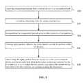
- a method for remote active testing of a device or network under testincludes:
- a remote test systemgenerating portions of test packets separated by time intervals, encapsulating the portions of test packets thereby forming encapsulated packets, and adding timing information to the encapsulated packets so as to preserve the portions of the test packets and information related to the time intervals;
- the local test devicedecapsulating the encapsulated packets so as to obtain replay packets and the timing information, wherein the replay packets include the portions of the test packets;
- Another aspect of the present inventionprovides a method of testing a communication device or network under test.
- the methodincludes:
- a local test devicereceiving encapsulated packets from a remote test system via a transport network, (ii) extracting timing information from the encapsulated packets, (iii) decapsulating the encapsulated packets so as to obtain portions of test packets, and (iv) forming replay packets, wherein the replay packets include the portions of the test packets; and,
- test deviceincluding:
- a packet input receiverfor receiving encapsulated packets from a network
- a packet readerfor extracting timing information from the encapsulated packets, for decapsulating encapsulated packets so as to obtain test packets, and for placing the test packets in a FIFO queue;
- a packet controllerfor reading the test packets from the FIFO queue and writing the test packets into a de-jitter buffer in accordance with the timing information
- a memory for the de-jitter bufferfor storing the reordered test packets
- a packet output generatorfor providing the test packets to a target device wherein time intervals between the test packets are reproduced using the timing information.
- FIG. 1is a schematic diagram of a test system for remote testing a device or network
- FIG. 2is a flow chart of a method of remote testing a device or network
- FIG. 3is a schematic diagram of a test replay device
- FIG. 4is a schematic diagram of the architecture of a test replay device
- FIG. 5is a flow chart of a method of testing a device or network performed at a local test device
- FIG. 6is a schematic diagram of a network test system for monitoring traffic in a network
- FIG. 7is a flow chart of a method of monitoring packet traffic
- FIG. 8is a flow chart of a method of monitoring packet traffic.
- FIG. 9is a schematic diagram of context of IPD communication flow and command elements in customer's network.
- a test systemincludes a remote test system 510 and one or more local test devices such as a probe 512 or probes 502 through 504 ; the remote test system 510 is in communication with the local devices test over a transport network 112 which may be any kind of a packet network.
- the probes 512 and 502 through 504may be interchangeable. In the system shown in FIG. 1 the probes differ in their use: the probe 512 is connected to a communication device under test (DUT) 514 ; the probes 502 through 504 are connected to a network under test 101 .
- DUTcommunication device under test
- the remote test system 510generates test packets which are sent over the transport network 112 e.g. to the local test device 512 and replayed therefrom to the device under test 514 ; the packet are encapsulated and their timing is preserved in the encapsulation.
- the packetsare decapsulated; the order of the test packets and inter-packet time intervals are restored based on timestamps retrieved from the encapsulation.
- the network under test 101may be the same network as the transport network 112 , or another network.
- the remote test system 510may be regularly updated to incorporate additional test configurations and protocols.
- the local test devicessuch as the probe 512 do not need to store test configurations and information related to protocols being tested.
- the local test devicesare protocol-independent as well as independent of test configuration.
- the local test devicesdo not require updates when a new protocol needs to be tested or new tests are implemented.
- the encapsulationallows mitigating delays and jitter associated with transmission of the test packets over the network 112 .
- remote testingis conducted in such a way that the network connecting the packet originator and the device under test is transparent and does not affect the test traffic.
- the encapsulationpreserves headers of the test packets, e.g. a destination address, which have been configured for a particular test by the remote test system 510 .
- the test packetsare transported over the network 112 without changes which happen when a packet is conventionally sent over a network without encapsulation.
- FIG. 2is a flow chart of a method of testing the DUT 514 or the network 101 .
- test packets or portions of test packetsseparated by time intervals.
- a test packetmay be a complete and fully formed packet including headers and frame check sequences, or may be an incomplete packet portion.
- test packet portionsinclude headers only, intentionally truncated packets such as runts, fully formed packets where the address field is not populated, and sliced packets that contain headers and some portion of payload. It may be useful to send portions of test packets to reduce upstream network bandwidth utilization.
- test packetsand “portions of test packets” are used interchangeably and encompass any portion having a non-zero length, up to and including an entire packet.
- the time intervals between the generated test packetsmay be either periodic or non-periodic intervals.
- the portions of the test packetsare encapsulated thereby forming encapsulated packets so as to preserve the portions of the test packets.
- Timing informationsuch as timestamps, and optionally sequencing information are added to the encapsulated packets so as to preserve information related to the time intervals.
- the timing informationmay indicate desired test timing in the generated packet stream: e.g. when to send the packet to the device under test, how many times to send the packet, and what should be time intervals.
- the test packetsare fragmented and/or encrypted before encapsulation.
- a transmission step 522includes transmitting the encapsulated packets over the transport network 112 from the remote test system 510 to the local test device 512 or 502 ;
- a decapsulation step 524is performed at the local test device, either the probe 512 for testing the DUT 514 , or at the probe 502 for testing the network 101 .
- the decapsulation step 524includes decapsulating the encapsulated packets so as to obtain replay packets and the timing information, preferably timestamps, wherein the replay packets include the portions of the test packets.
- the decapsulation step 524optionally includes decryption and/or reassembling the test packets if they have been fragmented and/or encrypted in the encapsulation step 521 .
- a local testing step 526includes transmitting the replay packets separated by the time intervals from the local test device 512 to the communication device under test 514 , or from the local test device 502 into the network under test 101 .
- the timestampsare used to reproduce the time intervals so as to imitate a stream of the test packets generated at the remote test system 510 .
- the missing information in the packetmay be added by the local test device.
- Examplesinclude inserting valid source and destination addressing for the segment the test packet is to be transmitted on, adding encapsulation to the packet so it may be routed on a network, adding random or defined payload bytes to make the packet a desired length or calculating and inserting valid packet checksums and frame check sequences to a packet. Additionally it may be useful to send a test packet portion without adding data to the packet. This may be useful for negative testing and error conditions on a network when a packet becomes corrupted.
- the remote test system 510includes a packet generator and an encapsulator.
- the packet generatorallows to build custom packets or select predefined packets to be generated on a communications network.
- the packet generator and the encapsulator of the system 510may be implemented separately or in a same device. In the former case, a conventional commercially available packet generator such as JDSU J6800 Network Analyzer, Spirent TestCenter, Ixia IX Load or similar equipment may be used to feed packets to the encapsulator.
- the encapsulatormay be implemented in a combination of software and hardware such as an Application Specific Integrated Circuit (ASIC), Field programmable Gate Array (FPGA), network processor, system on a chip such as an FPGA with integrated ARM or micro processor, Complex Programmable Logic Device (CPLD), Erasable programmable logic device (EPLD), Simple programmable logic device (SPLD), or macrocell array.
- ASICApplication Specific Integrated Circuit
- FPGAField programmable Gate Array
- CPLDComplex Programmable Logic Device
- EPLDErasable programmable logic device
- SPLDSimple programmable logic device
- the encapsulated packetsmay have the following general form: Network Encapsulation, which may include a TCP/UDP header, Command and Control Header, Test Packet.
- the Network Encapsulationincludes one or more headers which correspond to the protocols in use on the network leading up to the TCP (or UDP) layer.
- An Examplewould be Ethernet/IP.
- the network encapsulationmay include Virtual Local Area Network (VLAN), Multi-Protocol Label Switching (MPLS), Generic Routing Encapsulation (GRE), or any other routing or tunneling protocol.
- VLANVirtual Local Area Network
- MPLSMulti-Protocol Label Switching
- GREGeneric Routing Encapsulation
- TCP/UDP HeaderThe encapsulated packets transmitted to the local test device are sent over TCP to allow reliable transmission.
- transmissioncan be UDP, which is unreliable transport.
- the Command and Control (CC) Headeris formed during the encapsulation step 521 ( FIG. 2 ).
- the CC headerincludes the timing information, e.g. a timestamp indicating when the test packet originated at the packet generator.
- the CC headermay include sequence numbers, an identification number of the local test device, packet length, etc.
- the Test Packetis a packet generated at the generator within the remote test system 510 for the purpose of testing the DUT 514 or the network under test 101 .
- the test packetmay be encrypted; it may be fragmented and encapsulated within several encapsulation packets; it is also possible that only a slice (portion) of the original test packet is encapsulated and sent to the local test device; otherwise the test packets are unaltered.
- the Test Packetmay include the Ethernet header of the test packet generated at the remote test system 510 .
- the local test devices 512 and 502 through 504may include a packet input receiver 410 which receives encapsulated packets 405 from the network 112 , a packet reader/extractor 420 which extracts the timing information, e.g. timestamps and optionally sequence numbers, and decapsulates the encapsulated packets so as to obtain test packets.
- the local test devicesfurther include a memory for allocating a FIFO queue 430 where the reader 420 places the test packets.
- a packet controller 450reads the test packets from the FIFO queue 430 , reorders the packets using a de-jitter buffer 440 allocated in a memory of the test device, and provides the test packets in accordance with the timing information to a packet output generator 460 for sending the replay packets to a target device or network, in this case the DUT 514 or any device directly connected to the output port of the local test device.
- the above componentsmay be implemented in a combination of software and hardware such as an Application Specific Integrated Circuit (ASIC), Field programmable Gate Array (FPGA), network processor, system on a chip such as an FPGA with integrated ARM or micro processor, Complex Programmable Logic Device (CPLD), Erasable programmable logic device (EPLD), Simple programmable logic device (SPLD), or macrocell array.
- ASICApplication Specific Integrated Circuit
- FPGAField programmable Gate Array
- CPLDComplex Programmable Logic Device
- EPLDErasable programmable logic device
- SPLDSimple programmable logic device
- macrocell arraya decryption component and a defragmentation component not shown in FIG. 3 .
- the local test devicesact as test replay devices which preserve timing of the original stream of test packets remotely prepared for testing.
- FIG. 4illustrates the architecture of a test replay device such as the local test devices 512 and 502 through 504 .
- NIC 1 and NIC 2are separate network interface cards (NIC) or separate ports on a same NIC so that the Packet Playback never occurs on the same port where the Packet Feeds are being received.
- the replay applicationincludes two threads and a shared packet de-jitter buffer.
- the main applicationmanages the configuration through the user interface (UI). It also creates, configures, runs and stops all other objects in the system.
- the execution sequenceis as follows: initialization of the application and logging; log start time with command line; parse, validate command line parameters; perform command line parameter specific initialization including creating packet FIFO and de-jitter buffer; instantiate/initialize Packet Feed Reader/Extractor & Packet Playback threads, and wait for any status messages to be printed to console OR a signal to shut down.
- the encapsulated packetsare coming across the network it is certain that the packets in the feeds will arrive with some jitter. In other words, the time it takes a packet to traverse the transport network 112 will not be the same for all packets. While it may be close, there will always be some variance in the transit time which is what is referred to here as jitter. Since playback is timing sensitive, to maintain the original packet gap times, it is necessary to have some buffering to allow the jitter to be removed; accordingly, the replay device has a de-jitter buffer.
- the Packet Feed Reader/Extractor Threaddoes the following: Based on configuration, opens socket for UDP or TCP feeds; Waits on socket for incoming packets; If shutdown signal from Main Application, exit thread. The thread extracts original packet payload and queues it into the packet FIFO in time-order according to the timestamp in the header. If a packet is fragmented, reassembly must occur here. The thread inserts original payload plus pertinent information like timestamps and sequence numbers into Packet FIFO; then signals the playback thread and wait for more incoming packets.
- the Packet Playback Threaddoes the following:
- the packetneeds to be transmitted later. Queue the packet to the head of the de-jitter buffer. Adjust Sleep Tinier to wake up when the packet should be transmitted. Wait for more incoming packets.
- timestamp of the new packetis later than head of queue, queue the packet into the de-jitter buffer in time order; wait for more incoming packets.
- a signalis received from Sleep Timer, de-queue a head packet from de-jitter buffer and transmit it on NIC 2 ; Set Sleep Timer to wake when a next packet in de-jitter buffer should be transmitted; wait for more incoming packets.
- the aforedescribed replay algorithmsmay be implemented in a set of instructions stored on a tangible media to be executed by one or more processors.
- Advantages of the above methodinclude reduction of time and resources required to setup the data feed of interest because this can be done efficiently at the user's location w/o the need to directly access the equipment at the remote location; such setup does not require additional element ports or network/element configurations.
- the solutionis network-element agnostic, which means that users do not need to be skilled in multiple element features or operating systems to access the data.
- the simultaneous access to multiple testing points from a single locationallows for a reduced/localized investment of test tools.
- the data streamsare reproduced with accurate timing and sequencing so that the test tools get near real-time reproductions of the data which results in easier analysis and problem solving.
- Many network toolshave limited media connection options whereas points in the network can have various media types.
- the methodsolves the problem of remote access to the data of interest from one or more remote locations with the ability to filter the remote data and replay it locally with absolute timing and sequencing that would correct for any transport timing or sequencing impairments that occurred during transport from the remote location.
- the local test devices 512 and 502 through 504may use various time synchronization protocols such as Network Time Protocol (NIP) or IFEE 1588, or any other time synchronization method such as GPS, to synchronize time across a plurality of local test devices so as to synchronize streams of test packets pumped into the network under test 101 via multiple probes 502 through 504 .
- NIPNetwork Time Protocol
- IFEE 1588any other time synchronization method such as GPS
- the local test devices 512 and 502 through 504may communicate with the remote test system 510 e.g. by using the technique described in U.S. Pat. No. 7,336,673, which include forming a low bandwidth channel by inserting packets into a high bandwidth packet stream.
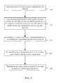
- FIG. 5illustrates a method performed at the local test device, such as the local test devices (probes) 502 and 512 through 514 .
- a receiving step 530includes receiving encapsulated packets from the remote test system 510 via the transport network 112 .
- a timestamp step 532includes extracting timestamps from the encapsulated packets.
- a decapsulation step 534the encapsulated packets are decapsulated so as to obtain portions of test packets.
- the decapsulation step 534may include decryption if the portions of the test packets have been encrypted and reassembling the test packets if they have been fragmented before the encapsulation.
- replay packetsare formed so as to include the portions of the test packets.
- the replay packetsmay be extended so as to have all the fields and lengths prescribed by the protocol(s).
- the command and control headerprovides the length and optionally pattern of bytes to append to the packet to make it the desired size; valid Frame Check Sequence (FCS) fields may also be added to the packets.
- FCSFrame Check Sequence
- a test traffic transmission step 538includes transmitting the replay packets from the local test device to the device or network under test.
- the local test device 512may transmit the replay packets to the communication device under test 514 , and the local test devices 502 through 504 —to the network under test 101 .
- the replay packetsare separated by the time intervals so as to imitate the test packets originated at the remote test system 510 , and wherein the time intervals are reproduced using the timestamps.
- the local test devices 512 and 502 through 504may be not assigned a unique IP address.
- the test systemmay implement a method for communication with such unaddressed devices.
- the remote test system 510may communicate with the local test device 512 as it had no address notwithstanding whether the local test device has a network address or not, making it effectively an unaddressed device.
- the remote test system 510may send encapsulated test packets over the network 112 to the unaddressed device 512 , wherein a destination address of the encapsulated packets is a network address of a downstream device that is downstream from the local test device 512 with respect to the remote test system 510 .
- a destination address of the encapsulated packetsis a network address of a downstream device that is downstream from the local test device 512 with respect to the remote test system 510 .
- a destination address of the encapsulated packetsis a network address of a downstream device that is downstream from the local test device 512 with respect to the remote test system 510 .
- a destination address of the encapsulated packetsis a network address of a downstream device that is downstream from the local test device 512 with respect to the remote test system 510 .
- addresses of several downstream devicesmay be used.
- An unaddressed test devicecontains an identification code that is used to determine whether packets received by the unaddressed device are intended to or of interest for this particular device.
- the unaddressed inline test deviceinspects each received packet with the help of a configurable protocol header parser. Based on the information in the headers and payload, the unaddressed inline network test device identifies information targeted to this device. When a packet is identified as having information targeted or of interest for the test device, the information is extracted and processed and the test device decapsulates the payload intended for transmission on the communication network.
- a network test system for monitoring traffic in a network 101includes an Intelligent Packet Director (IPD) 100 and a mediator 120 , optionally the system may include a routing engine 150 .
- the network 101may be any kind of a packet network.
- the intelligent packet director 100is connected at a network access point 130 to the network 101 for capturing traffic packets passing therethrough, or at least portions of the packets, e.g. headers.
- traffic packetsand “portions of traffic packets” are used interchangeably and encompass any portion having a non-zero length, up to and including an entire packet.
- Time intervals separating the traffic packetsmay be non-periodic time intervals.
- the IPD 100may capture all packets passing therethrough or may apply a filter so as to get only particular packets e.g. selected by a byte pattern, destination or a protocol.
- the IPD 100performs encapsulating the captured traffic packets so as to form encapsulated packets.
- the encapsulationis necessary in order to preserve the captured data and transport it over a network 112 to a different location without changes such as changes to the destination address field which happen when a packet is conventionally sent over a network without encapsulation.
- the network 112may be the same network 101 where the packets are captured, or another network.
- the IPD 100may be a test device inserted inline between one or more elements capable of communicating information over a communication network.
- the IPD 100may use various time synchronization protocols such as Network Time Protocol (NTP) or IEEE 1588, or any other time synchronization method such as GPS, to synchronize time across a plurality of test devices.
- NTPNetwork Time Protocol
- the IPD 100contains information needed to communicate packets on an inline sub-channel.
- the IPD 100monitors the traffic passing therethrough and may replicate the traffic either selectively or non-selectively. For selective replication the IPD 100 may have metrics stored therein for selecting some of the passing packets.
- the IPD 100inspects data contained in network packets passing through it.
- a configurable protocol header parsermay be used in the IPD 100 to identify and inspect known and unknown protocol headers.
- the IPD 100When the IPD 100 identifies a packet meeting particular criteria, the packet or its portion is replicated, time stamped and stored in an elastic buffer.
- the IPD 100constructs an encapsulated packet which contains timing information, such as a timestamp and optionally sequencing information, and responds using addresses stored in memory.
- the IPD 100may use techniques described in U.S. Pat. No. 7,336,673 to form a low bandwidth channel by inserting packets into a high bandwidth packet stream.
- network nodesmay act as probes by copying some traffic packets to an additional output port; the nodes may have the IPD capabilities.
- the IPD 100may be a separate device, either having a network address or an unaddressed network test device.
- the IPD 100adds timestamps to the encapsulated packets so as to preserve the information related to the time intervals.
- sequence informationsuch as sequence numbers may be added to the encapsulated packets.
- the captured datamay be encrypted using conventional encryption methods.
- the timestamps added to the encapsulating portion of the captured packetsare referred to as “capture timestamps” since they represent the time when each packet was captured by the IPD 100 .
- the capture timestampsare different from the timestamps which may already be present in the packet prior to the capture, such as Real-Time Transport Protocol (RTP) timestamps or MPEG Decode Time Stamp (DTS) and Presentation Time Stamp (PTS) timestamps; these pre-existing timestamps are preserved as part of the captured packet which is encapsulated so as not to change on transmission to a remote device.
- RTPReal-Time Transport Protocol
- DTSMPEG Decode Time Stamp
- PTSPresentation Time Stamp
- the process of capturing the data and encapsulationintroduces a delay between the moment when the data was captured and the capture timestamp was added to the encapsulated packet.
- the delaysare very small, and are substantially the same from packet to packet.
- the systematic delaydoes not present a problem.
- the IPD 100transmits the encapsulated packets over the network 112 to the mediator 120 .
- FIG. 6shows the networks 112 and 101 as two separate networks.
- one of the two networksmay be a wireless network and another—a wireline (optical or electrical) network.
- the IPD 100 and the mediator 120may be connected via a wide area network (WAN); the routing engine 150 may be used for routing encapsulated packets form multiple IPD devices to one or more mediator devices such as the mediator 120 shown in FIG. 6 .
- WANwide area network
- the mediator 120also referred to as a Packet Delivery Gateway (PDG) 120 , is connected to the same network 112 whereto the IPD 100 is connected, and receives the encapsulated packets over the network 112 from the IPD 100 ; the network 112 may be the same network 101 where the traffic packets are captured.
- the PDGmay be a standalone element or may be implemented in software such as a virtual Network Interface Controller (NIC) or Network Driver Interface Specification (NDIS) driver installed on a general purpose or specialized computer.
- NICvirtual Network Interface Controller
- NDISNetwork Driver Interface Specification
- the mediator 120extracts the capture timestamps and decapsulates the encapsulated packets and reassembles them, if they have been fragmented across multiple packets, so as to obtain the original packets, or packet portions which have been captured by the IPD 100 .
- the mediator 120use this decapsulated data to form replay packets which are the same traffic packets captured at the probe 100 .
- the replay packetsmay be extended so as to have all the fields and lengths prescribed by the protocol(s); valid Frame Check Sequence (FCS) fields may also be added to the packets.
- FCSFrame Check Sequence
- the mediator 120transmits the replay packets to a target device 140 , e.g. a network analyzer such as Wireshark.
- the replay packetsare separated by the same time intervals as the corresponding traffic packets captured at the probe 100 , wherein the timestamps are used to reproduce the time intervals so as to imitate the traffic packets passing through the access point 130 .
- sequence numbersmay be used to identify lost data and to order received encapsulated packets prior to decapsulation and thus partially compensate for any jitter or missequencing on the path between the IPD 100 and mediator 120 .
- the captured datamay be encrypted at the IPD 100 and decrypted at the mediator 120 for secure transport over a public network; a variety of conventional encryption algorithms may be used.
- the mediator 120may receive encapsulated packets captured at several probes, e.g. probes 103 and 104 shown in FIG. 6 . In addition to receiving encapsulated packets from remote sources, the mediator 120 may receive and buffer packets from local sources. The mediator 120 may merge all received streams and replay them with accurate timing that comes from the capture timestamps So that the target device 140 receives time-aligned streams from multiple points in a network. If the probes 100 , 103 and 104 are synchronized, the multiple streams may be used to measure a delay between disparate points in the network.
- a method of monitoring packet trafficincludes a capturing step 210 which involves capturing portions of traffic packets passing therethrough separated by time intervals, and an encapsulation step 220 which involves encapsulating the portions of traffic packets thereby forming encapsulated packets and adding timestamps and optionally sequence numbers and/or additional packet metrics to the encapsulated packets so as to preserve the portions of traffic packets and information related to the time intervals, both steps 210 and 220 performed at a first access point.
- the methodalso includes a transmission step 230 where the encapsulated packets are transmitted over a network 112 , which may be the monitored network 101 or another network.
- the encapsulated packetsAfter the encapsulated packets have been received from the network 112 , they are decapsulated in a decapsulation step 240 so as to obtain replay packets and the capture timestamps, wherein the replay packets include the portions of the traffic packets.
- a replay step 250the replay packets separated by the time intervals are transmitted to a packet analyzing device; the timestamps are used to reproduce the inter packet time intervals; and sequence numbers may be used to identify lost packets. Consequently, the stream received at the analyzing device imitates the traffic packets passing through the first access point wherein the inter-packet intervals are preserved.
- the mediator 120may generate an identification packet in place of the lost packet to identify its loss.
- FIG. 8illustrates a method of monitoring traffic packets passing through a first access point by a remote device; the method is performed at the mediator 120 and includes the following steps:
- an information request step 310receiving a request for providing portions of the traffic packets captured at the first access point to the remote device, an information request step 310 ;
- decapsulating the encapsulated packetsso as to obtain the portions of the traffic packets captured at the first access point, a decapsulating step 350 ;
- replay packetsinclude the portions of the traffic packets; a replay packets step 360 ; and,
- the transmitting step 370transmitting the replay packets from the mediator to the remote device, wherein the replay packets are separated by the time intervals so as to imitate the traffic packets passing through the first access point, and wherein the time intervals are reproduced using the timestamps, the transmitting step 370 .
- the mediator 120includes a packet input receiver 410 which receives encapsulated packets 405 from the network 112 , a packet reader/extractor 420 which extracts the timestamps and optionally sequence numbers and packet metrics, and decapsulates packets.
- the mediator 120further includes memory means for allocating a FIFO queue 430 and a de jitter buffer 440 , a packet controller 450 , and a packet output generator 460 for providing the replay packets to the target device as discussed above with reference to the test devices 512 and 502 through 504 .
- the above componentsmay be implemented in a combination of software and hardware such as an Application Specific Integrated Circuit (ASIC), Field programmable Gate Array (FPGA), network processor, system on a chip such as an FPGA with integrated ARM or micro processor, Complex Programmable Logic Device (CPLD), Erasable programmable logic device (EPLD), Simple programmable logic device (SPLD), or macrocell array.
- ASICApplication Specific Integrated Circuit
- FPGAField programmable Gate Array
- CPLDComplex Programmable Logic Device
- EPLDErasable programmable logic device
- SPLDSimple programmable logic device
- An IPDmay be installed inline with edge devices like switches, routers, Digital Subscriber Line Access Multiplexers (DSLAMs), Broadband Remote Access Servers (BRASs), Cable Modem Termination System (CMTSs), Optical Line Terminals (OLTs), and Ethernet Node Bs.
- An IPDmay also be installed anywhere a conventional Small Form-factor Pluggable (SFP) transceiver might be placed.
- SFPSmall Form-factor Pluggable
- the IPDsmay be instructed to look at all frames passing on the link and perform matched filter-logic over each packet. When a match occurs the IPD extracts data from the copy if needed and constructs a results-packet that encapsulates the copy.
- the encapsulated packetscan contain the entire original packet or its portion, e.g. the header or truncated data.
- the encapsulated packetsmay be assigned a destination address of the mediator 120 or the routing engine 150 .
- the encapsulated packetsare assigned a destination address of a Packet Routing Engine (PRE) 150 , then inserted into the communication sub-channel to make their way to the Packet Routing Engine (PRE) 150 .
- the Packet Routing Engine 150is assigned a set of IPD devices to talk to and to receive encapsulated packets from those devices.
- the Packet Routing Engine 150processes the encapsulated packets for specific target applications and forwards them to the appropriate end-user application(s) e.g. at the Central Office. End-user applications use PDG software or drivers to decapsulate the original captured packets.
- the encapsulated packetsmay be sent to multiple targets from the PRE 150 if desired.
- the mediator 120may be registered with multiple Packet Routing Engines via the System Manager 160 shown in FIG. 9 , for receipt of various encapsulated packets network-wide.
- the PRE or System managerWhen receiving routed encapsulated packets, the PRE or System manager conducts its analytics pre-processing and transforms the raw packet data into reports or for other use or analysis.
- User applicationsmay also dynamically instruct the System manager to refine the IPDs monitoring by enabling/disabling other filters and/or supply an alternative source and destination addresses to the Packet Routing Engine 150 through an open application programming integration interface (API).
- APIapplication programming integration interface
- the encapsulated packets received at the PDG 120may have the following general form: Network Encapsulation, TCP/UDP header, Command and Control Header, Original Packet.
- the Network Encapsulationis one or more headers which correspond to the protocols in use on the network leading up to the TCP (or UDP) layer.
- An Examplewould be Ethernet/IP.
- the network encapsulationmay include e VLAN, Multi-Protocol Label Switching (MPLS), Generic Routing Encapsulation (GRE), or any other routing or tunneling protocol.
- MPLSMulti-Protocol Label Switching
- GREGeneric Routing Encapsulation
- TCP/UDP HeaderThe packet payload being transmitted to the PDG is sent over TCP to allow reliable transmission.
- transmissioncan be UDP, which is unreliable transport.
- the Command and Control (CC) Headeris formed during the encapsulation step 220 ( FIG. 7 ).
- the CC headerincludes the capture timestamp indicating when the original packet was captured at the IPD that sent it.
- the CC headermay include sequence numbers, metrics of captured traffic or the particular packet, IPD identification number, packet length, etc.
- the Original Packetis the traffic packet as captured by the IPD.
- the original packetmay be fragmented between several encapsulation packets, and/or be only a slice (portion) of the original packet; otherwise the captured packet is unaltered.
- the Original Packet portionmay include the Ethernet header of the captured packet.
- FIG. 9shows a basic distributed deployment of the traffic monitoring system.
- the IPDs 100are usually plugged into routers, DSLAMs and OLTs at the Edge but could be used throughout the service provider's network.
- the Packet Routing Engines (PREs) 150usually sit on the customer network between the Production and Backhaul networks and act as command agents as well as result routers to terminating applications like Wireshark, Snort, PDG, Next Generation Network Analysis System (NGNAS), Triple Play Analyzer (TPA) disclosed in U.S. Pat. No. 7,688,754, 3rd party tools, etc., that are used to analyze or measure network packets or data; such tools include protocol analyzers, Quality of Service (QoS) monitors, signaling analyzers, security applications, intrusion detection systems, lawful intercept applications, forensics, performance and response time measures and other network monitoring and troubleshooting tools. They provide a single destination for all command and control communication for an IPD as well as the captured result packets from filtering operations.
- QoSQuality of Service
- the Packet Delivery Gateways (PDGs) 120may be located within the customer's trusted network and provide an endpoint destination for processing result packet streams from one or more PREs or IPDs.
- PDGscontain a core driver library of functionality for un-marshalling result packets from PREs or IPDs for use by other applications 140 ( FIG. 6 ).
- a Master Clockcan provide time synchronization for IPDs through the PREs.
- the PREsperform all time synchronization with IPDs through its Command and Control protocol stack.
- the Master Configuration System and Database server 160may be located at the customer core management site and is the central point of control.
- a capture device with time-stamping and optional filtering capabilitycopies packets with optional filtering from the network; the packets of interest are encapsulated for transmission to a remote destination; the encapsulated packets are time-stamped and optionally provided with sequence numbers and other metrics.
- a transport network 112transports encapsulated packets of interest from the Capture device IPD 100 to a packet replay layer.
- the PDG device 120receives encapsulated packets of interest from the transport network from one or more devices; it may also receive a local stream on an alternate port which is time-stamped and buffered; the PDG 120 removes transport encapsulations from remote streams, sequences and de-jitters packets to smooth packet replay, may merge multiple streams preserving timing, may also merge remote streams with a buffered local stream, and replays reproduced packet streams on a local network port to a target device 140 with accurate inter-packet timing reproduction; the local network port may be a physical network port or a logical communications port within the test replay device PDG 120 .
- a user configuration and control interfaceallows a user to select network access device(s) such as the IPD 100 and may configure filters for network access device(s) so as to identify packets of interest; the user may configure a number of packets to capture or duration of packet capture; and the user starts packet capture. When several PDG devices are available, the user may select test replay device to receive packets therefrom.
- the user configuration and control interfacemay be implemented in the System Manager 160 ; alternatively this functionality may be implemented in the PDG, PRE or alternate device receiving the data stream.
- the packet analysis tool 140connects to a local network port on the test replay device 120 and performs desired packet analysis.
- traffic packetsare selected using filters on the IPD 100 and packaged and sent up to the IPD′s owning PRE 150 .
- the original traffic packetscan be travelling upstream or downstream at the IPD. Which ones are sent to the PRE 150 as part of the feed is determined by how the filter is programmed on the IPD 100 .
- every IPD 100sends the encapsulated packets to the PRE 150 , which forwards the packet feed to any application registered to receive them; in this case the application is the PDG 120 .
- the PDG 120then un-packages the traffic packets and replays them onto a local network.
- Packet Analyzers 140represent consumers of the packets that are being replayed.
- FIG. 4illustrates the architecture of the PDG layer.
- the replay algorithm described above with reference to FIG. 4may be implemented in a set of instructions stored on a tangible media to be executed by one or more processors.
- the local test devices 512 and 502 through 504 and the mediator 120act as test replay devices which preserve timing of the original stream of test packets, either remotely prepared for testing as in the case of the local test devices, or remotely obtained during testing as in the case of the mediator 120 .
- Advantages of the above methodinclude reduction of time and resources required to setup the data feed of interest because this can be done efficiently at the user's location w/o the need to directly access the equipment at the remote location; such setup does not require additional element ports or network/element configurations.
- the solutionis network-element agnostic, which means that users do not need to be skilled in multiple element features or operating systems to access the data.
- the simultaneous access to multiple points with the data being aggregated to a single locationallows for a reduced/localized investment of test tools.
- the data streamsare reproduced with accurate timing and sequencing so that the test tools get near real-time reproductions of the data which results in easier analysis and problem solving.
- Many network toolshave limited media connection options whereas points in the network can have various media types.
- the methodsallows to collect the data of interest from a variety of different media types and deliver them on a single supported media interface simultaneously.
- the methodsolves the problem of remote access to the data of interest from one or more remote locations with the ability to filter the remote data and replay it locally with absolute timing and sequencing that would correct for any transport timing or sequencing impairments that occurred during transport from the remote location.
- the method disclosed hereinprovides for an inline test device to timestamp and sequence packets as they are captured. This is advantageous because a receiving device will be able to accurately reproduce packet timing and sequencing as it occurred at the test device.
- the systemcommunicates replicated packets to a receiving device that is not locally connected, possibly using the same network being monitored.
- the methodallows for a receiving device to receive an encapsulated replicated packet and transmit the carrying packets contents on an egress port to a secondary receiving device that is not capable of interpreting carrying packets. It further provides for the packets transmitted over an egress port to be transmitted with accurate inter-packet timing and sequencing based on the timestamps and sequence numbers in the carrying packet.
- the mediatorallows to use existing packet traffic analysis tools to analyze the packets as if they were originally occurring on the local network.
- processorsmay be provided through the use of dedicated hardware as well as hardware capable of executing software in association with appropriate software.
- the functionsmay be provided by a single dedicated processor, by a single shared processor, or by a plurality of individual processors, some of which may be shared or distributed.
- explicit use of the term “processor” or “controller”should not be construed to refer exclusively to hardware capable of executing software, and may include, without limitation, digital signal processor (DSP) hardware, read only memory (ROM) for storing software, random access memory (RAM), and non-volatile storage.
- DSPdigital signal processor
- ROMread only memory
- RAMrandom access memory
Landscapes
- Engineering & Computer Science (AREA)
- Computer Networks & Wireless Communication (AREA)
- Signal Processing (AREA)
- Health & Medical Sciences (AREA)
- Cardiology (AREA)
- General Health & Medical Sciences (AREA)
- Environmental & Geological Engineering (AREA)
- Data Exchanges In Wide-Area Networks (AREA)
Abstract
Description
Claims (14)
Priority Applications (1)
| Application Number | Priority Date | Filing Date | Title |
|---|---|---|---|
| US13/107,752US8654790B2 (en) | 2010-06-15 | 2011-05-13 | Method of remote active testing of a device or network |
Applications Claiming Priority (3)
| Application Number | Priority Date | Filing Date | Title |
|---|---|---|---|
| US35507510P | 2010-06-15 | 2010-06-15 | |
| US35504010P | 2010-06-15 | 2010-06-15 | |
| US13/107,752US8654790B2 (en) | 2010-06-15 | 2011-05-13 | Method of remote active testing of a device or network |
Publications (2)
| Publication Number | Publication Date |
|---|---|
| US20110305150A1 US20110305150A1 (en) | 2011-12-15 |
| US8654790B2true US8654790B2 (en) | 2014-02-18 |
Family
ID=44514445
Family Applications (4)
| Application Number | Title | Priority Date | Filing Date |
|---|---|---|---|
| US13/104,708Active2031-11-27US8705395B2 (en) | 2010-06-15 | 2011-05-10 | Method for time aware inline remote mirroring |
| US13/107,752Active2032-01-27US8654790B2 (en) | 2010-06-15 | 2011-05-13 | Method of remote active testing of a device or network |
| US14/194,177Active2031-06-28US9106520B2 (en) | 2010-06-15 | 2014-02-28 | Method for time aware inline remote mirroring |
| US14/822,223Expired - Fee RelatedUS9503342B2 (en) | 2010-06-15 | 2015-08-10 | Method for time aware inline remote mirroring |
Family Applications Before (1)
| Application Number | Title | Priority Date | Filing Date |
|---|---|---|---|
| US13/104,708Active2031-11-27US8705395B2 (en) | 2010-06-15 | 2011-05-10 | Method for time aware inline remote mirroring |
Family Applications After (2)
| Application Number | Title | Priority Date | Filing Date |
|---|---|---|---|
| US14/194,177Active2031-06-28US9106520B2 (en) | 2010-06-15 | 2014-02-28 | Method for time aware inline remote mirroring |
| US14/822,223Expired - Fee RelatedUS9503342B2 (en) | 2010-06-15 | 2015-08-10 | Method for time aware inline remote mirroring |
Country Status (3)
| Country | Link |
|---|---|
| US (4) | US8705395B2 (en) |
| EP (3) | EP2398189A1 (en) |
| CN (2) | CN102291272B (en) |
Cited By (8)
| Publication number | Priority date | Publication date | Assignee | Title |
|---|---|---|---|---|
| US20130212263A1 (en)* | 2012-02-15 | 2013-08-15 | VSS Monitoring | Encapsulating data packets |
| US20140301221A1 (en)* | 2013-03-14 | 2014-10-09 | Exfo Inc. | Pass-Through Test Device |
| US9313116B2 (en) | 2013-02-13 | 2016-04-12 | ViaviSolutions Inc. | Enhanced retry method |
| US9525750B2 (en) | 2013-02-13 | 2016-12-20 | Viavi Solutions Inc. | Method of collecting information about test devices in a network |
| US9858137B2 (en)* | 2013-12-04 | 2018-01-02 | Exfo Inc. | Network test system |
| RU2676024C2 (en)* | 2014-11-05 | 2018-12-25 | Зте Корпорейшн | Method, device, system, implementing remote bridge connection, and computer storage media |
| US10917326B1 (en)* | 2019-08-23 | 2021-02-09 | Keysight Technologies, Inc. | Methods, systems, and computer readable media for debugging test traffic generation |
| US11792299B1 (en) | 2022-06-09 | 2023-10-17 | Amazon Technologies, Inc. | Distribution of messages with guaranteed or synchronized time of delivery |
Families Citing this family (105)
| Publication number | Priority date | Publication date | Assignee | Title |
|---|---|---|---|---|
| US8705395B2 (en)* | 2010-06-15 | 2014-04-22 | Jds Uniphase Corporation | Method for time aware inline remote mirroring |
| JP2012133414A (en)* | 2010-12-17 | 2012-07-12 | Fujitsu Ltd | Testing device, testing method and testing program |
| US20120307626A1 (en)* | 2011-05-31 | 2012-12-06 | Alcatel-Lucent Canada Inc. | Field-deployable protocol message interceptor |
| US8595393B2 (en)* | 2011-05-31 | 2013-11-26 | Alcatel Lucent | Message flow rerouting for self-disrupting network element |
| US9736065B2 (en) | 2011-06-24 | 2017-08-15 | Cisco Technology, Inc. | Level of hierarchy in MST for traffic localization and load balancing |
| AU2012320198B2 (en)* | 2011-10-06 | 2017-10-26 | Telefonaktiebolaget L M Ericsson (Publ) | Test traffic interceptor in a data network |
| US9106353B2 (en) | 2011-12-13 | 2015-08-11 | Jds Uniphase Corporation | Time synchronization for network testing equipment |
| US8908698B2 (en) | 2012-01-13 | 2014-12-09 | Cisco Technology, Inc. | System and method for managing site-to-site VPNs of a cloud managed network |
| US9141506B2 (en)* | 2012-02-15 | 2015-09-22 | Jds Uniphase Corporation | Method and system for network monitoring using signature packets |
| US9438502B2 (en)* | 2012-02-17 | 2016-09-06 | Viavi Solutions Inc. | Controlling generation of filtered result packets |
| US8908539B1 (en)* | 2012-05-25 | 2014-12-09 | Google Inc. | Systems and methods for testing network connections of a centrally-controlled network |
| US8751615B2 (en) | 2012-07-18 | 2014-06-10 | Accedian Networks Inc. | Systems and methods of discovering and controlling devices without explicit addressing |
| US8830869B2 (en) | 2012-07-18 | 2014-09-09 | Accedian Networks Inc. | Systems and methods of detecting and assigning IP addresses to devices with ARP requests |
| US8862702B2 (en) | 2012-07-18 | 2014-10-14 | Accedian Networks Inc. | Systems and methods of installing and operating devices without explicit network addresses |
| US9735874B2 (en) | 2012-07-18 | 2017-08-15 | Accedian Networks Inc. | Programmable small form-factor pluggable module |
| US9106706B2 (en) | 2012-07-18 | 2015-08-11 | Accedian Networks Inc. | Systems and methods of using beacon messages to discover devices across subnets |
| US9218266B2 (en)* | 2012-07-23 | 2015-12-22 | Infosys Limited | Systems and methods for replication of test results in a network environment |
| US20140071855A1 (en) | 2012-09-10 | 2014-03-13 | Accedian Networks Inc. | Transparent auto-negotiation of ethernet |
| WO2014070883A2 (en) | 2012-10-30 | 2014-05-08 | Jds Uniphase Corporation | Method and system for identifying matching packets |
| US10367914B2 (en) | 2016-01-12 | 2019-07-30 | Cisco Technology, Inc. | Attaching service level agreements to application containers and enabling service assurance |
| CN104025549B (en)* | 2012-12-18 | 2017-04-05 | 英特尔公司 | Postpone the related technology of information to server transaction |
| US9628209B2 (en)* | 2013-01-17 | 2017-04-18 | Viavi Solutions Inc. | Time synchronization in distributed network testing equipment |
| US9325564B1 (en) | 2013-02-21 | 2016-04-26 | Google Inc. | GRE tunnels to resiliently move complex control logic off of hardware devices |
| US9043439B2 (en)* | 2013-03-14 | 2015-05-26 | Cisco Technology, Inc. | Method for streaming packet captures from network access devices to a cloud server over HTTP |
| US9438497B2 (en) | 2013-05-06 | 2016-09-06 | Viavi Solutions Inc. | Method and system for measuring packet loss |
| US20150029871A1 (en)* | 2013-07-24 | 2015-01-29 | Cisco Technology, Inc. | Service level agreement validation via service traffic sample-and-replay |
| US10027569B1 (en)* | 2014-08-07 | 2018-07-17 | Amdocs Development Limited | System, method, and computer program for testing virtual services |
| US10063453B1 (en) | 2014-08-07 | 2018-08-28 | Amdocs Development Limited | System, method, and computer program for tag based testing of virtual services |
| US9755858B2 (en) | 2014-04-15 | 2017-09-05 | Cisco Technology, Inc. | Programmable infrastructure gateway for enabling hybrid cloud services in a network environment |
| US9300565B2 (en) | 2014-04-17 | 2016-03-29 | Accedian Networks Inc. | System and method for out-of-line real-time in-service performance measurement |
| US9473365B2 (en) | 2014-05-08 | 2016-10-18 | Cisco Technology, Inc. | Collaborative inter-service scheduling of logical resources in cloud platforms |
| US11539611B2 (en) | 2014-05-08 | 2022-12-27 | Microsoft Technology Licensing, Llc | Fine-grained network monitoring |
| CN103986624B (en)* | 2014-05-28 | 2017-08-08 | 西安交通大学 | A kind of network flow recovery back method |
| CN104009889B (en)* | 2014-06-10 | 2017-04-26 | 西安西电捷通无线网络通信股份有限公司 | Communication protocol testing method and tested equipment and testing platform of communication protocol testing method |
| US10122605B2 (en) | 2014-07-09 | 2018-11-06 | Cisco Technology, Inc | Annotation of network activity through different phases of execution |
| US9806987B2 (en)* | 2014-07-30 | 2017-10-31 | Futurewei Technologies, Inc. | Method and apparatus for reducing response time in information-centric networks |
| US9825878B2 (en) | 2014-09-26 | 2017-11-21 | Cisco Technology, Inc. | Distributed application framework for prioritizing network traffic using application priority awareness |
| WO2016100545A1 (en)* | 2014-12-16 | 2016-06-23 | Noderprime, Inc. | Computer servers for datacenter managment |
| US10050862B2 (en) | 2015-02-09 | 2018-08-14 | Cisco Technology, Inc. | Distributed application framework that uses network and application awareness for placing data |
| US10037617B2 (en) | 2015-02-27 | 2018-07-31 | Cisco Technology, Inc. | Enhanced user interface systems including dynamic context selection for cloud-based networks |
| US10708342B2 (en) | 2015-02-27 | 2020-07-07 | Cisco Technology, Inc. | Dynamic troubleshooting workspaces for cloud and network management systems |
| US10382534B1 (en) | 2015-04-04 | 2019-08-13 | Cisco Technology, Inc. | Selective load balancing of network traffic |
| US10476982B2 (en) | 2015-05-15 | 2019-11-12 | Cisco Technology, Inc. | Multi-datacenter message queue |
| CN105023410B (en)* | 2015-05-26 | 2018-08-24 | 江苏林洋能源股份有限公司 | A kind of zero-address pattern micropower wireless meter-reading method |
| US10034201B2 (en) | 2015-07-09 | 2018-07-24 | Cisco Technology, Inc. | Stateless load-balancing across multiple tunnels |
| US10067780B2 (en) | 2015-10-06 | 2018-09-04 | Cisco Technology, Inc. | Performance-based public cloud selection for a hybrid cloud environment |
| US11005682B2 (en) | 2015-10-06 | 2021-05-11 | Cisco Technology, Inc. | Policy-driven switch overlay bypass in a hybrid cloud network environment |
| US10462136B2 (en) | 2015-10-13 | 2019-10-29 | Cisco Technology, Inc. | Hybrid cloud security groups |
| KR102460350B1 (en)* | 2015-11-06 | 2022-10-28 | 삼성전자주식회사 | Method and apparatus for transmitting and receiving data in communication system |
| US10523657B2 (en) | 2015-11-16 | 2019-12-31 | Cisco Technology, Inc. | Endpoint privacy preservation with cloud conferencing |
| US10205677B2 (en) | 2015-11-24 | 2019-02-12 | Cisco Technology, Inc. | Cloud resource placement optimization and migration execution in federated clouds |
| US10084703B2 (en) | 2015-12-04 | 2018-09-25 | Cisco Technology, Inc. | Infrastructure-exclusive service forwarding |
| US10026509B2 (en)* | 2015-12-18 | 2018-07-17 | Architecture Technology Corporation | Low bandwidth media stream transmission |
| KR101785821B1 (en)* | 2016-01-04 | 2017-10-16 | 엘에스산전 주식회사 | Method of monitoring frame receiving in serial communication |
| US10075522B2 (en)* | 2016-01-29 | 2018-09-11 | Extreme Networks, Inc. | Automated mirroring and remote switch port analyzer (RSPAN)/ encapsulated remote switch port analyzer (ERSPAN) functions using fabric attach (FA) signaling |
| US10097633B2 (en) | 2016-01-29 | 2018-10-09 | Extreme Networks, Inc. | Automated mirroring and remote switch port analyzer (RSPAN)/encapsulated remote switch port analyzer (ERSPAN) functions using fabric attach (FA) signaling |
| CN107305515A (en)* | 2016-04-25 | 2017-10-31 | Emc公司 | Computer implemented method, computer program product and computing system |
| US10129177B2 (en) | 2016-05-23 | 2018-11-13 | Cisco Technology, Inc. | Inter-cloud broker for hybrid cloud networks |
| US10659283B2 (en) | 2016-07-08 | 2020-05-19 | Cisco Technology, Inc. | Reducing ARP/ND flooding in cloud environment |
| US10432532B2 (en) | 2016-07-12 | 2019-10-01 | Cisco Technology, Inc. | Dynamically pinning micro-service to uplink port |
| US10263898B2 (en) | 2016-07-20 | 2019-04-16 | Cisco Technology, Inc. | System and method for implementing universal cloud classification (UCC) as a service (UCCaaS) |
| US10382597B2 (en) | 2016-07-20 | 2019-08-13 | Cisco Technology, Inc. | System and method for transport-layer level identification and isolation of container traffic |
| US10142346B2 (en) | 2016-07-28 | 2018-11-27 | Cisco Technology, Inc. | Extension of a private cloud end-point group to a public cloud |
| US10567344B2 (en) | 2016-08-23 | 2020-02-18 | Cisco Technology, Inc. | Automatic firewall configuration based on aggregated cloud managed information |
| US10523592B2 (en) | 2016-10-10 | 2019-12-31 | Cisco Technology, Inc. | Orchestration system for migrating user data and services based on user information |
| US10250486B2 (en)* | 2016-10-14 | 2019-04-02 | Gvbb Holdings S.A.R.L. | System and method for isochronous switching of packetized media streams |
| US11044162B2 (en) | 2016-12-06 | 2021-06-22 | Cisco Technology, Inc. | Orchestration of cloud and fog interactions |
| US10326817B2 (en) | 2016-12-20 | 2019-06-18 | Cisco Technology, Inc. | System and method for quality-aware recording in large scale collaborate clouds |
| US10419396B2 (en)* | 2016-12-22 | 2019-09-17 | Vmware, Inc. | Deep packet inspection with enhanced data packet analyzers |
| US10334029B2 (en) | 2017-01-10 | 2019-06-25 | Cisco Technology, Inc. | Forming neighborhood groups from disperse cloud providers |
| US10552191B2 (en) | 2017-01-26 | 2020-02-04 | Cisco Technology, Inc. | Distributed hybrid cloud orchestration model |
| US10320683B2 (en) | 2017-01-30 | 2019-06-11 | Cisco Technology, Inc. | Reliable load-balancer using segment routing and real-time application monitoring |
| US10671571B2 (en) | 2017-01-31 | 2020-06-02 | Cisco Technology, Inc. | Fast network performance in containerized environments for network function virtualization |
| US11005731B2 (en) | 2017-04-05 | 2021-05-11 | Cisco Technology, Inc. | Estimating model parameters for automatic deployment of scalable micro services |
| US10439877B2 (en) | 2017-06-26 | 2019-10-08 | Cisco Technology, Inc. | Systems and methods for enabling wide area multicast domain name system |
| US10382274B2 (en) | 2017-06-26 | 2019-08-13 | Cisco Technology, Inc. | System and method for wide area zero-configuration network auto configuration |
| US10425288B2 (en) | 2017-07-21 | 2019-09-24 | Cisco Technology, Inc. | Container telemetry in data center environments with blade servers and switches |
| US10892940B2 (en) | 2017-07-21 | 2021-01-12 | Cisco Technology, Inc. | Scalable statistics and analytics mechanisms in cloud networking |
| US10601693B2 (en) | 2017-07-24 | 2020-03-24 | Cisco Technology, Inc. | System and method for providing scalable flow monitoring in a data center fabric |
| US10541866B2 (en) | 2017-07-25 | 2020-01-21 | Cisco Technology, Inc. | Detecting and resolving multicast traffic performance issues |
| US10353800B2 (en) | 2017-10-18 | 2019-07-16 | Cisco Technology, Inc. | System and method for graph based monitoring and management of distributed systems |
| US11481362B2 (en) | 2017-11-13 | 2022-10-25 | Cisco Technology, Inc. | Using persistent memory to enable restartability of bulk load transactions in cloud databases |
| CN108011878A (en)* | 2017-11-29 | 2018-05-08 | 复旦大学 | The remote testing analogue system and method for facing multiple users design of hardware and software project |
| CN108881958B (en)* | 2017-11-30 | 2020-02-21 | 视联动力信息技术股份有限公司 | Multimedia data stream packaging method and device |
| US10705882B2 (en) | 2017-12-21 | 2020-07-07 | Cisco Technology, Inc. | System and method for resource placement across clouds for data intensive workloads |
| US11595474B2 (en) | 2017-12-28 | 2023-02-28 | Cisco Technology, Inc. | Accelerating data replication using multicast and non-volatile memory enabled nodes |
| US10511534B2 (en) | 2018-04-06 | 2019-12-17 | Cisco Technology, Inc. | Stateless distributed load-balancing |
| US10728361B2 (en) | 2018-05-29 | 2020-07-28 | Cisco Technology, Inc. | System for association of customer information across subscribers |
| US10904322B2 (en) | 2018-06-15 | 2021-01-26 | Cisco Technology, Inc. | Systems and methods for scaling down cloud-based servers handling secure connections |
| US10764266B2 (en) | 2018-06-19 | 2020-09-01 | Cisco Technology, Inc. | Distributed authentication and authorization for rapid scaling of containerized services |
| US11019083B2 (en) | 2018-06-20 | 2021-05-25 | Cisco Technology, Inc. | System for coordinating distributed website analysis |
| US10862938B1 (en) | 2018-06-21 | 2020-12-08 | Architecture Technology Corporation | Bandwidth-dependent media stream compression |
| US10812562B1 (en) | 2018-06-21 | 2020-10-20 | Architecture Technology Corporation | Bandwidth dependent media stream compression |
| US10819571B2 (en) | 2018-06-29 | 2020-10-27 | Cisco Technology, Inc. | Network traffic optimization using in-situ notification system |
| US10904342B2 (en) | 2018-07-30 | 2021-01-26 | Cisco Technology, Inc. | Container networking using communication tunnels |
| CN108965061B (en)* | 2018-08-03 | 2024-02-02 | 上海欣诺通信技术股份有限公司 | Data packet capturing device and method, restoring device and method, system and medium |
| US10999173B2 (en)* | 2018-11-19 | 2021-05-04 | Cisco Technology, Inc. | Active targeted data plane traffic monitoring for wired networks |
| CN109525461B (en)* | 2018-11-27 | 2020-09-08 | 杭州迪普科技股份有限公司 | Network equipment testing method, device, equipment and storage medium |
| EP3709177B1 (en)* | 2019-03-13 | 2021-03-03 | Axis AB | Serial peripheral interface master |
| CN111478862B (en)* | 2020-03-09 | 2022-02-22 | 邦彦技术股份有限公司 | Remote data mirroring system and method |
| US11252064B2 (en) | 2020-07-01 | 2022-02-15 | Hewlett Packard Enterprise Development Lp | System and method for monitoring ingress/egress packets at a network device |
| US11601406B2 (en) | 2020-08-19 | 2023-03-07 | Netscout Systems, Inc. | Decrypting synthetic transactions with beacon packets |
| CN113708990B (en)* | 2021-08-06 | 2022-12-27 | 上海龙旗科技股份有限公司 | Method and equipment for packet grabbing and unpacking of data packet |
| US11777833B2 (en) | 2021-09-15 | 2023-10-03 | International Business Machines Corporation | Non-intrusive disaster recovery and resilience |
| US20250211505A1 (en)* | 2023-12-20 | 2025-06-26 | Arista Networks, Inc. | Using Generic Routing Encapsulation (GRE) for Carrying Monitored Network Traffic |
Citations (32)
| Publication number | Priority date | Publication date | Assignee | Title |
|---|---|---|---|---|
| US5185860A (en) | 1990-05-03 | 1993-02-09 | Hewlett-Packard Company | Automatic discovery of network elements |
| US6108782A (en)* | 1996-12-13 | 2000-08-22 | 3Com Corporation | Distributed remote monitoring (dRMON) for networks |
| US6286039B1 (en) | 1997-08-28 | 2001-09-04 | Cisco Technology, Inc. | Automatic static to dynamic IP address and DNS address management for remote communications network access |
| US20010039579A1 (en)* | 1996-11-06 | 2001-11-08 | Milan V. Trcka | Network security and surveillance system |
| US20020059516A1 (en)* | 2000-11-16 | 2002-05-16 | Esa Turtiainen | Securing Voice over IP traffic |
| US20030135612A1 (en)* | 2001-07-17 | 2003-07-17 | Huntington Stephen Glen | Full time network traffic recording systems and methods |
| US20030223376A1 (en) | 2002-05-30 | 2003-12-04 | Agilent Technologies, Inc. | Testing network communications |
| US20040001443A1 (en)* | 2002-06-26 | 2004-01-01 | Soon Shih Chung | Controlled exception-based routing protocol validation |
| US20040071095A1 (en)* | 2001-02-28 | 2004-04-15 | Vilho Raisanen | Quality of service monitor |
| US20040208129A1 (en) | 2003-04-17 | 2004-10-21 | Agilent Technologies, Inc. | Testing network communications |
| US20050108379A1 (en)* | 2003-08-01 | 2005-05-19 | West Ridge Networks, Inc. | System and methods for simulating traffic generation |
| US20060140125A1 (en)* | 2004-12-23 | 2006-06-29 | Telefonaktiebolaget Lm Ericsson | Hybrid test bed |
| US20060159080A1 (en)* | 2005-01-14 | 2006-07-20 | Citrix Systems, Inc. | Methods and systems for generating playback instructions for rendering of a recorded computer session |
| GB2426145A (en) | 2005-05-12 | 2006-11-15 | Agilent Technologies Inc | Protocol-generic eavesdropping network device |
| US20070006292A1 (en) | 2003-02-06 | 2007-01-04 | Inniminate Security Technologies Ag | Method and system for the transparent transmission of data traffic between data processing devices, corresponding computer program product, and corresponding computer-readable storage medium |
| US7324562B1 (en)* | 2002-12-20 | 2008-01-29 | Cypress Semiconductor Corporation | Method and apparatus for introducing differential delay between virtually concatenated tributaries |
| US7336673B2 (en) | 2003-10-17 | 2008-02-26 | Agilent Technologies, Inc. | Creating a low bandwidth channel within a high bandwidth packet stream |
| US7337233B2 (en) | 1994-06-08 | 2008-02-26 | Hughes Network Systems, Inc. | Network system with TCP/IP protocol spoofing |
| US20080120081A1 (en)* | 2006-11-17 | 2008-05-22 | Chandrashekar Karthikeyan | Modeling and simulating flow propagation in dynamic bandwidth systems |
| US20080198742A1 (en)* | 2007-02-18 | 2008-08-21 | Gideon Kaempfer | Method and system for testing stateful network communications devices |
| US20080285452A1 (en)* | 2007-05-14 | 2008-11-20 | Cisco Technology, Inc. | Remote monitoring of real-time internet protocol media streams |
| WO2009001067A2 (en) | 2007-06-23 | 2008-12-31 | Calnex Solutions Ltd | Network in-line tester |
| US7506065B2 (en) | 2003-11-26 | 2009-03-17 | Hewlett-Packard Development Company, L.P. | Remote mirroring using IP encapsulation |
| US7688754B2 (en) | 2006-08-03 | 2010-03-30 | Acterna Llc | Triple play services tester |
| US7733773B2 (en) | 2006-10-18 | 2010-06-08 | Telefonaktiebolaget Lm Ericsson (Publ) | Playout based delay scheduler |
| US7804832B2 (en) | 2006-02-13 | 2010-09-28 | Cisco Technology, Inc. | Method and system for simplified network wide traffic and/or flow monitoring in a data network |
| US20110075577A1 (en)* | 2009-09-30 | 2011-03-31 | Bing Chen | Systems and methods to measure the performance of a de-jitter buffer |
| US20110158240A1 (en) | 2008-08-29 | 2011-06-30 | Zte Corporation | Method and apparatus for realizing unicast reverse path forwarding |
| US20110208849A1 (en)* | 2010-02-25 | 2011-08-25 | General Electric Company | Method and system for security maintenance in a network |
| US20110305149A1 (en)* | 2010-06-15 | 2011-12-15 | Jds Uniphase Corporation | Method for time aware inline remote mirroring |
| US20110310745A1 (en)* | 2008-12-31 | 2011-12-22 | Telecom Italia S.P.A. | Method and system for simulating the physical level of a radio network |
| US20120084605A1 (en)* | 2010-10-04 | 2012-04-05 | Hanan Shilon | Replaying captured network traffic |
Family Cites Families (4)
| Publication number | Priority date | Publication date | Assignee | Title |
|---|---|---|---|---|
| CN100471138C (en)* | 2004-04-22 | 2009-03-18 | 华为技术有限公司 | A method for monitoring packet data service |
| US20050281392A1 (en)* | 2004-06-18 | 2005-12-22 | Covaro Networks, Inc. | System and method for connection performance analysis |
| US7907532B2 (en)* | 2005-11-23 | 2011-03-15 | Jds Uniphase Corporation | Pool-based network diagnostic systems and methods |
| US7484146B2 (en)* | 2006-06-06 | 2009-01-27 | Litepoint Corp. | Method for capturing multiple data packets in a data signal for analysis |
- 2011
- 2011-05-10USUS13/104,708patent/US8705395B2/enactiveActive
- 2011-05-11EPEP11165728Apatent/EP2398189A1/ennot_activeCeased
- 2011-05-11EPEP11165681.5Apatent/EP2398188B1/ennot_activeNot-in-force
- 2011-05-11EPEP17155874.5Apatent/EP3211833A1/ennot_activeWithdrawn
- 2011-05-13USUS13/107,752patent/US8654790B2/enactiveActive
- 2011-05-16CNCN201110125638.4Apatent/CN102291272B/ennot_activeExpired - Fee Related
- 2011-05-16CNCN201110125383.1Apatent/CN102291291B/ennot_activeExpired - Fee Related
- 2014
- 2014-02-28USUS14/194,177patent/US9106520B2/enactiveActive
- 2015
- 2015-08-10USUS14/822,223patent/US9503342B2/ennot_activeExpired - Fee Related
Patent Citations (32)
| Publication number | Priority date | Publication date | Assignee | Title |
|---|---|---|---|---|
| US5185860A (en) | 1990-05-03 | 1993-02-09 | Hewlett-Packard Company | Automatic discovery of network elements |
| US7337233B2 (en) | 1994-06-08 | 2008-02-26 | Hughes Network Systems, Inc. | Network system with TCP/IP protocol spoofing |
| US20010039579A1 (en)* | 1996-11-06 | 2001-11-08 | Milan V. Trcka | Network security and surveillance system |
| US6108782A (en)* | 1996-12-13 | 2000-08-22 | 3Com Corporation | Distributed remote monitoring (dRMON) for networks |
| US6286039B1 (en) | 1997-08-28 | 2001-09-04 | Cisco Technology, Inc. | Automatic static to dynamic IP address and DNS address management for remote communications network access |
| US20020059516A1 (en)* | 2000-11-16 | 2002-05-16 | Esa Turtiainen | Securing Voice over IP traffic |
| US20040071095A1 (en)* | 2001-02-28 | 2004-04-15 | Vilho Raisanen | Quality of service monitor |
| US20030135612A1 (en)* | 2001-07-17 | 2003-07-17 | Huntington Stephen Glen | Full time network traffic recording systems and methods |
| US20030223376A1 (en) | 2002-05-30 | 2003-12-04 | Agilent Technologies, Inc. | Testing network communications |
| US20040001443A1 (en)* | 2002-06-26 | 2004-01-01 | Soon Shih Chung | Controlled exception-based routing protocol validation |
| US7324562B1 (en)* | 2002-12-20 | 2008-01-29 | Cypress Semiconductor Corporation | Method and apparatus for introducing differential delay between virtually concatenated tributaries |
| US20070006292A1 (en) | 2003-02-06 | 2007-01-04 | Inniminate Security Technologies Ag | Method and system for the transparent transmission of data traffic between data processing devices, corresponding computer program product, and corresponding computer-readable storage medium |
| US20040208129A1 (en) | 2003-04-17 | 2004-10-21 | Agilent Technologies, Inc. | Testing network communications |
| US20050108379A1 (en)* | 2003-08-01 | 2005-05-19 | West Ridge Networks, Inc. | System and methods for simulating traffic generation |
| US7336673B2 (en) | 2003-10-17 | 2008-02-26 | Agilent Technologies, Inc. | Creating a low bandwidth channel within a high bandwidth packet stream |
| US7506065B2 (en) | 2003-11-26 | 2009-03-17 | Hewlett-Packard Development Company, L.P. | Remote mirroring using IP encapsulation |
| US20060140125A1 (en)* | 2004-12-23 | 2006-06-29 | Telefonaktiebolaget Lm Ericsson | Hybrid test bed |
| US20060159080A1 (en)* | 2005-01-14 | 2006-07-20 | Citrix Systems, Inc. | Methods and systems for generating playback instructions for rendering of a recorded computer session |
| GB2426145A (en) | 2005-05-12 | 2006-11-15 | Agilent Technologies Inc | Protocol-generic eavesdropping network device |
| US7804832B2 (en) | 2006-02-13 | 2010-09-28 | Cisco Technology, Inc. | Method and system for simplified network wide traffic and/or flow monitoring in a data network |
| US7688754B2 (en) | 2006-08-03 | 2010-03-30 | Acterna Llc | Triple play services tester |
| US7733773B2 (en) | 2006-10-18 | 2010-06-08 | Telefonaktiebolaget Lm Ericsson (Publ) | Playout based delay scheduler |
| US20080120081A1 (en)* | 2006-11-17 | 2008-05-22 | Chandrashekar Karthikeyan | Modeling and simulating flow propagation in dynamic bandwidth systems |
| US20080198742A1 (en)* | 2007-02-18 | 2008-08-21 | Gideon Kaempfer | Method and system for testing stateful network communications devices |
| US20080285452A1 (en)* | 2007-05-14 | 2008-11-20 | Cisco Technology, Inc. | Remote monitoring of real-time internet protocol media streams |
| WO2009001067A2 (en) | 2007-06-23 | 2008-12-31 | Calnex Solutions Ltd | Network in-line tester |
| US20110158240A1 (en) | 2008-08-29 | 2011-06-30 | Zte Corporation | Method and apparatus for realizing unicast reverse path forwarding |
| US20110310745A1 (en)* | 2008-12-31 | 2011-12-22 | Telecom Italia S.P.A. | Method and system for simulating the physical level of a radio network |
| US20110075577A1 (en)* | 2009-09-30 | 2011-03-31 | Bing Chen | Systems and methods to measure the performance of a de-jitter buffer |
| US20110208849A1 (en)* | 2010-02-25 | 2011-08-25 | General Electric Company | Method and system for security maintenance in a network |
| US20110305149A1 (en)* | 2010-06-15 | 2011-12-15 | Jds Uniphase Corporation | Method for time aware inline remote mirroring |
| US20120084605A1 (en)* | 2010-10-04 | 2012-04-05 | Hanan Shilon | Replaying captured network traffic |
Non-Patent Citations (6)
| Title |
|---|
| Claise et al., "Packet Sampling (PSAMP) Protocol Specifications; rfc5476.txt", Packet Sampling (PSAMP) Protocol Specification; RFC5476 TXT, Internet Engineering Task Force, IETF; Standard, Internet Society (ISOC) 4, Rue Des Falaises CH- 1205 Geneva, Switzerland, Mar. 1, 2009, XP015065545. |
| Enns et al., "Device Discovery Protocol (DDP) draft-marques-ddp-00.txt; draft-marques-ddp-00.txt", IETF Standard-Working-Draft, Internet Engineering Task Force, IETF, CH, May 2003. |
| European Search Report from EP application No. 11165681.5. |
| European Search Report from EP application No. 11165728.4. |
| European Search Report from EP application No. 11165984.3. |
| Kaeo et al., "Methodology for Benchmarking IPsec Devices; draft-ietf-bmwg-ipsec-met h-05.txt",Methodology for Benchmarking IPsec Devices; draft-ietf-bmwg-ipsec-met h-05.txt, Internet Engineering Task Force, IETF; Standardworkingdraft, Internet Society (ISOC) 4, Rue Des Falaises CH-1205 Geneva, Switzerland, vol. bmwg, No. 5, Jul. 28, 2009, XP015063661. |
Cited By (11)
| Publication number | Priority date | Publication date | Assignee | Title |
|---|---|---|---|---|
| US20130212263A1 (en)* | 2012-02-15 | 2013-08-15 | VSS Monitoring | Encapsulating data packets |
| US9729408B2 (en)* | 2012-02-15 | 2017-08-08 | Vss Monitoring, Inc. | Encapsulating data packets |
| US9313116B2 (en) | 2013-02-13 | 2016-04-12 | ViaviSolutions Inc. | Enhanced retry method |
| US9525750B2 (en) | 2013-02-13 | 2016-12-20 | Viavi Solutions Inc. | Method of collecting information about test devices in a network |
| US10419322B2 (en) | 2013-02-13 | 2019-09-17 | Viavi Solutions Inc. | Method of collecting information about test devices in a network |
| US20140301221A1 (en)* | 2013-03-14 | 2014-10-09 | Exfo Inc. | Pass-Through Test Device |
| US9450854B2 (en)* | 2013-03-14 | 2016-09-20 | Exfo Inc. | Pass-through test device |
| US9858137B2 (en)* | 2013-12-04 | 2018-01-02 | Exfo Inc. | Network test system |
| RU2676024C2 (en)* | 2014-11-05 | 2018-12-25 | Зте Корпорейшн | Method, device, system, implementing remote bridge connection, and computer storage media |
| US10917326B1 (en)* | 2019-08-23 | 2021-02-09 | Keysight Technologies, Inc. | Methods, systems, and computer readable media for debugging test traffic generation |
| US11792299B1 (en) | 2022-06-09 | 2023-10-17 | Amazon Technologies, Inc. | Distribution of messages with guaranteed or synchronized time of delivery |
Also Published As
| Publication number | Publication date |
|---|---|
| CN102291291B (en) | 2016-08-31 |
| US9106520B2 (en) | 2015-08-11 |
| CN102291291A (en) | 2011-12-21 |
| EP2398188A1 (en) | 2011-12-21 |
| US8705395B2 (en) | 2014-04-22 |
| US9503342B2 (en) | 2016-11-22 |
| EP2398189A1 (en) | 2011-12-21 |
| US20140177465A1 (en) | 2014-06-26 |
| EP3211833A1 (en) | 2017-08-30 |
| US20110305149A1 (en) | 2011-12-15 |
| CN102291272B (en) | 2016-05-25 |
| US20110305150A1 (en) | 2011-12-15 |
| US20160156533A1 (en) | 2016-06-02 |
| EP2398188B1 (en) | 2015-09-16 |
| CN102291272A (en) | 2011-12-21 |
Similar Documents
| Publication | Publication Date | Title |
|---|---|---|
| US8654790B2 (en) | Method of remote active testing of a device or network | |
| CN111837361B (en) | Method for collecting network OAM flow data by using out-of-band message and network node | |
| US10419322B2 (en) | Method of collecting information about test devices in a network | |
| CN100463418C (en) | Network performance testing method, system and network equipment | |
| US9882666B2 (en) | Time synchronization for network testing equipment | |
| US8520540B1 (en) | Remote traffic monitoring through a network | |
| DK2730059T3 (en) | Oam open flow driven by controller | |
| US9450846B1 (en) | System and method for tracking packets in a network environment | |
| US9331920B2 (en) | Media path monitoring over a secure network | |
| US9313116B2 (en) | Enhanced retry method | |
| WO2019071598A1 (en) | Method and device for transmitting and receiving clock synchronization message | |
| CN100382517C (en) | Network service quality testing method and system | |
| WO2018210213A1 (en) | Method and device for implementing ioam packaging and storage medium | |
| CN111327445B (en) | Message sampling method, message unpacking method, node, system and storage medium | |
| WO2019085809A1 (en) | Method, relevant device and system for acquiring a target transmission path | |
| US20140156867A1 (en) | Offload processing interface | |
| KR102058766B1 (en) | Method for monitoring a wireless link of a wi-fi node of a customer premises equipment device, and customer premises equipment device utilizing the method | |
| WO2006105707A1 (en) | A network performance testing method and the system, the device thereof | |
| EP1943787B1 (en) | Method and system for loop-back and continue in packet-based network | |
| CN113364778B (en) | Message processing method and device | |
| CN107835109B (en) | Method and system for testing packet transport network defined by software | |
| WO2025103035A1 (en) | Network performance monitoring method and apparatus | |
| CN119892695A (en) | Time delay measurement method, time delay measurement device, forwarding node and storage medium |
Legal Events
| Date | Code | Title | Description |
|---|---|---|---|
| AS | Assignment | Owner name:JDS UNIPHASE CORPORATION, CALIFORNIA Free format text:ASSIGNMENT OF ASSIGNORS INTEREST;ASSIGNORS:HAVER, JOE;HIDAI, TAKASHI;BAUER, SAM;AND OTHERS;REEL/FRAME:026279/0532 Effective date:20110510 | |
| STCF | Information on status: patent grant | Free format text:PATENTED CASE | |
| AS | Assignment | Owner name:VIAVI SOLUTIONS INC., CALIFORNIA Free format text:CHANGE OF NAME;ASSIGNOR:JDS UNIPHASE CORPORATION;REEL/FRAME:036504/0327 Effective date:20150731 | |
| FEPP | Fee payment procedure | Free format text:PAYOR NUMBER ASSIGNED (ORIGINAL EVENT CODE: ASPN); ENTITY STATUS OF PATENT OWNER: LARGE ENTITY Free format text:PAYER NUMBER DE-ASSIGNED (ORIGINAL EVENT CODE: RMPN); ENTITY STATUS OF PATENT OWNER: LARGE ENTITY | |
| FPAY | Fee payment | Year of fee payment:4 | |
| AS | Assignment | Owner name:WELLS FARGO BANK, NATIONAL ASSOCIATION, AS ADMINISTRATIVE AGENT, COLORADO Free format text:SECURITY INTEREST;ASSIGNORS:VIAVI SOLUTIONS INC.;3Z TELECOM, INC.;ACTERNA LLC;AND OTHERS;REEL/FRAME:052729/0321 Effective date:20200519 | |
| MAFP | Maintenance fee payment | Free format text:PAYMENT OF MAINTENANCE FEE, 8TH YEAR, LARGE ENTITY (ORIGINAL EVENT CODE: M1552); ENTITY STATUS OF PATENT OWNER: LARGE ENTITY Year of fee payment:8 | |
| AS | Assignment | Owner name:RPC PHOTONICS, INC., NEW YORK Free format text:TERMINATIONS OF SECURITY INTEREST AT REEL 052729, FRAME 0321;ASSIGNOR:WELLS FARGO BANK, NATIONAL ASSOCIATION, AS ADMINISTRATIVE AGENT;REEL/FRAME:058666/0639 Effective date:20211229 Owner name:VIAVI SOLUTIONS INC., CALIFORNIA Free format text:TERMINATIONS OF SECURITY INTEREST AT REEL 052729, FRAME 0321;ASSIGNOR:WELLS FARGO BANK, NATIONAL ASSOCIATION, AS ADMINISTRATIVE AGENT;REEL/FRAME:058666/0639 Effective date:20211229 | |
| FEPP | Fee payment procedure | Free format text:MAINTENANCE FEE REMINDER MAILED (ORIGINAL EVENT CODE: REM.); ENTITY STATUS OF PATENT OWNER: LARGE ENTITY |