US8653322B2 - Intravaginal device with fluid transport plates - Google Patents
Intravaginal device with fluid transport platesDownload PDFInfo
- Publication number
- US8653322B2 US8653322B2US10/847,952US84795204AUS8653322B2US 8653322 B2US8653322 B2US 8653322B2US 84795204 AUS84795204 AUS 84795204AUS 8653322 B2US8653322 B2US 8653322B2
- Authority
- US
- United States
- Prior art keywords
- fluid
- plate
- fluid transport
- storage element
- transport element
- Prior art date
- Legal status (The legal status is an assumption and is not a legal conclusion. Google has not performed a legal analysis and makes no representation as to the accuracy of the status listed.)
- Active, expires
Links
- PQXAPVOKLYINEI-GVHYBUMESA-NCCC1C[C@H](C)CC1Chemical compoundCCC1C[C@H](C)CC1PQXAPVOKLYINEI-GVHYBUMESA-N0.000description1
Images


Classifications
- A—HUMAN NECESSITIES
- A61—MEDICAL OR VETERINARY SCIENCE; HYGIENE
- A61F—FILTERS IMPLANTABLE INTO BLOOD VESSELS; PROSTHESES; DEVICES PROVIDING PATENCY TO, OR PREVENTING COLLAPSING OF, TUBULAR STRUCTURES OF THE BODY, e.g. STENTS; ORTHOPAEDIC, NURSING OR CONTRACEPTIVE DEVICES; FOMENTATION; TREATMENT OR PROTECTION OF EYES OR EARS; BANDAGES, DRESSINGS OR ABSORBENT PADS; FIRST-AID KITS
- A61F13/00—Bandages or dressings; Absorbent pads
- A61F13/15—Absorbent pads, e.g. sanitary towels, swabs or tampons for external or internal application to the body; Supporting or fastening means therefor; Tampon applicators
- A61F13/20—Tampons, e.g. catamenial tampons; Accessories therefor
- A61F13/2022—Tampons, e.g. catamenial tampons; Accessories therefor characterised by the shape
- A61F13/2031—Tampons, e.g. catamenial tampons; Accessories therefor characterised by the shape having depressions or elevations, e.g. dots, lines
- A—HUMAN NECESSITIES
- A61—MEDICAL OR VETERINARY SCIENCE; HYGIENE
- A61F—FILTERS IMPLANTABLE INTO BLOOD VESSELS; PROSTHESES; DEVICES PROVIDING PATENCY TO, OR PREVENTING COLLAPSING OF, TUBULAR STRUCTURES OF THE BODY, e.g. STENTS; ORTHOPAEDIC, NURSING OR CONTRACEPTIVE DEVICES; FOMENTATION; TREATMENT OR PROTECTION OF EYES OR EARS; BANDAGES, DRESSINGS OR ABSORBENT PADS; FIRST-AID KITS
- A61F13/00—Bandages or dressings; Absorbent pads
- A61F13/15—Absorbent pads, e.g. sanitary towels, swabs or tampons for external or internal application to the body; Supporting or fastening means therefor; Tampon applicators
- A61F13/20—Tampons, e.g. catamenial tampons; Accessories therefor
- A61F13/2002—Tampons, e.g. catamenial tampons; Accessories therefor characterised by the use
- A61F13/202—Catamenial tampons
Definitions
- the present inventionrelates to intravaginal devices (e.g., tampons) for capturing and storing bodily fluid.
- intravaginal devicese.g., tampons
- Intravaginal tamponsare the most common example of such devices.
- Commercially available tamponsare generally compressed cylindrical masses of absorbent fibers that may be over-wrapped with an absorbent or nonabsorbent cover layer.
- the tamponis inserted into the human vagina and retained there for a time for the purpose of capturing and storing intravaginal bodily fluids, most commonly menstrual fluid. As intravaginal bodily fluid contacts the tampon, it should be absorbed and retained by the absorbent material of the tampon. After a time, the tampon and its retained fluid is removed and disposed, and if necessary, another tampon is inserted.
- a drawback often encountered with commercially available tamponsis the tendency toward premature failure, which may be defined as bodily fluid leakage from the vagina while the tampon is in place, and before the tampon is completely saturated with the bodily fluid.
- the patent arttypically describes a problem believed to occur that an unexpanded, compressed tampon is unable to immediately absorb fluid. Therefore, it presumes that premature leakage may occur when bodily fluid contacts a portion of the compressed tampon, and the fluid is not readily absorbed. The bodily fluid may bypass the tampon.
- U.S. Pat. No. 4,212,301discloses a unitary constructed digital tampon having a lower portion compressed preferably in the radial direction to form a rigid, rod-like element, which provides a central rigidified elongated core and an upper portion left substantially uncompressed. After insertion, the uncompressed portion may be manipulated to contact the vaginal wall to provide an immediate seal against side leakage. The uncompressed portion allows for high absorbent capacity immediately upon insertion. While this tampon may allow for a certain amount of protection from bypass leakage, the uncompressed portion may become saturated before the compressed portion has a chance to expand and become absorbent.
- U.S. Pat. No. 6,358,235discloses a “hollow” bag-like tampon that may have an interior projection made from highly compressed absorbent material.
- the interior projectionis preferably attached to the inside surface of the head of the tampon.
- the hollow tampon portionmay include at least one pleat in the absorbent outer surface and is soft and conformable.
- the tamponis not pre-compressed to the point where the fibers temporarily “set” and re-expand upon the absorption of fluid.
- the absorbent portions of the tamponcan saturate locally, which leads to bypass leakage.
- U.S. Pat. No. 6,177,608discloses a tampon having nonwoven barrier strips which are outwardly spreadable from the tampon surface to reliably close the free spaces believed to exist within a vaginal cavity.
- the nonwoven barrier stripsextend about the tampon in a circumferential direction at the surface or in a helical configuration about the tampon and purportedly conduct menstrual fluid toward the tampon surface.
- the nonwoven barrier stripsare attached to the cover by means of gluing, heat sealing, needle punching, embossing or the like and form pleats.
- the nonwoven barrier stripsare attached to the tampon blank and the blank is embossed, forming grooves extending in a longitudinal direction.
- U.S. Pat. No. 6,206,867suggests that a desirable tampon has at least a portion of which is dry expanding to cover a significant portion of the vaginal interior immediately upon deployment.
- a tamponhaving a compressed central absorbent core having at least one flexible panel attached along a portion of the side surface of the core.
- the flexible panelappears to provide the “dry-expanding” function, and it extends outwardly from the core away from the point of attachment.
- the flexible panelcontacts the inner surfaces of the vagina when the tampon is in place and purportedly directs fluid toward the absorbent core.
- the flexible panelis typically attached to the pledget prior to compression of the pledget to form the absorbent core and remains in an uncompressed state.
- U.S. Pat. No. 5,817,077discloses a method of preserving natural moisture of vaginal epithelial tissue while a using a tampon where the tampon has an initial capillary suction pressure at the outer surface of less than about 40 mm Hg. This allows the tampon to absorb vaginal secretions without substantially drying the vaginal epithelial tissue.
- the multiple cover layerscan be used to increase the thickness of the cover material. While this represents a significant advancement in the art, this invention does not address by-pass leakage.
- U.S. Pat. No. 5,545,155discloses an external absorbent article that has a set of plates separated by spacer elements. The plates may be treated to affect wettability so that fluid will flow easily across the surface. Extending through the upper plate is a plurality of openings, which allow fluid to flow with little restriction into the space between the upper and lower plates. When the fluid flows downward in the z-direction from the upper plate to the lower plate, it will then flow laterally in the x- and y-directions. Therefore, this external absorbent article can contain fluid gushes, but it does not appear to address the problems relating in particular to intravaginal devices, such as a tampon.
- the present inventionis not dependent on the expansion of the compressed absorbent, but rather, it directs the fluid by the use of inter-plate capillary action. In our invention, we minimize local saturation of the fluid storage element. Our invention also is effective for handling highly viscous menstrual fluid.
- an intravaginal devicehas a fluid storage element having a longitudinal axis.
- the fluid storage elementis in fluid communication with at least one fluid transport element.
- the at least one fluid transport elementhas a first plate having an outwardly oriented surface and an inwardly oriented surface and a second plate coupled to the first plate.
- the second platehas a first surface disposed and maintained in facing relationship with the inwardly oriented surface of the first plate and an opposite surface.
- the second plateis capable of separating from the first plate sufficiently to provide inter-plate capillary action.
- the at least one fluid transport elementis bendable about an axis substantially parallel to the longitudinal axis of the fluid storage element.
- a tamponhas a fluid storage element having a longitudinal axis.
- the fluid storage elementis in fluid communication with a plurality of fluid transport elements.
- Each fluid transport elementhas a first plate formed of an apertured polymeric formed film and having an outwardly oriented surface and an inwardly oriented surface, and a second plate, spaced apart from the first plate, also formed of an apertured polymeric formed film and having a first surface disposed in facing relationship with the inwardly oriented surface of the first plate, and an opposite surface.
- the apertured polymeric formed filmis a resilient three-dimensional web having first and second web surfaces. The first web surface has a multiplicity of apertures therein.
- Each of the aperturesis defined by a multiplicity of intersecting elements interconnected to one another substantially in the plane of the first web surface.
- Each of the intersecting elementsexhibits a cross-section comprising a base portion in the plane of the first web surface and a sidewall portion joined to each edge of the base portion.
- the sidewall portionsextend generally in the direction of the second web surface, and they are interconnected to one another intermediate the first and the second web surfaces. The interconnected sidewall portions terminate substantially concurrently with one another in the plane of the second web surface.
- FIG. 1 ashows a side elevation of an intravaginal device having a pair of fluid transport elements formed as extensions of a cover.
- FIG. 1 bshows a transverse cross-section of the device in 1 a along line 1 b - 1 b.
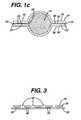
- FIG. 1 cshows the transverse cross-section shown in 1 b , after the introduction of a fluid between the plates of the fluid transport element.
- FIGS. 2 a - cshow enlarged cross-sections of alternate embodiments of fluid transport elements of the present invention formed of polymeric apertured formed film having differing orientations of the formed film plates.
- FIG. 3shows an enlarged cross-section of an alternate embodiment of a fluid transport element of the present invention having nubbles to separate a set of film plates.
- FIGS. 4 a - eshow various aspects and orientations of an intravaginal device of the present invention.
- FIG. 4 ashows a perspective view of a tampon having a plurality of fluid transport elements extending therefrom that are formed from a folded sheet material.
- FIG. 4 bshows a side elevation of the tampon with a plurality of fluid transport elements wrapped around the fluid storage element.
- FIG. 4 cshows a transverse cross-section along line 4 c - 4 c in FIG. 4 b.
- FIG. 4 dshows a side elevation of the tampon of FIG. 4 a.
- FIG. 4 eshows a top elevation of the tampon of FIG. 4 a.
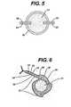
- FIG. 5shows a transverse cross-section of an alternate embodiment having a pair of fluid transport elements partially extending into the storage element.
- FIG. 6shows a transverse cross-section of a human vagina with a tampon according to FIG. 4 b disposed therein with one fluid transport element extending away from the fluid storage element.
- FIG. 7shows a transverse cross-section of a human vagina with a tampon according to FIG. 4 b disposed therein with the fluid transport elements remaining wrapped around the fluid storage element.
- FIG. 8 ashows a side elevation of an alternate embodiment of the present invention in which fluid transport elements connect a plurality of fluid storage elements.
- FIG. 8 bshows a transverse cross-section along line 8 b - 8 b . in FIG. 8 a.
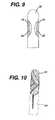
- FIG. 9shows an axial cross-section of an alternative embodiment of a device according to the present invention.
- FIG. 10shows the device of FIG. 4 contained in a tampon applicator packaging element.
- bodily fluidand variants thereof mean bodily exudates, especially liquids that are produced by, secreted by, emanate from, and/or discharged from a human body.
- fluidsrelate to liquids, and especially bodily fluids.
- sheetand variants thereof relates to a portion of something that is thin in comparison to its length and breadth.
- parallel plateand variants thereof relates to a system of at least two relatively parallel sheets that are capable of moving fluids through inter-plate capillary action.
- the individual “plates” in the systemmay be flexible and/or resilient in order to move within their environment. However, they may be maintained in a substantially facing relationship with relatively constant separation at least in a localized portion of their structure (as compared with their relative length and width).
- two sheetscould be fluted, but if the flutes are “nested”, the sheets would generally remain generally parallel in any given localized portion.
- inter-plate capillary actionand variants thereof mean the movement of fluid due to a pressure difference across a liquid-air meniscus created within a gap between two substantially parallel plates.
- the two platesneed not be held apart a specific distance, although they should be separable to allow fluid to move between them by inter-plate capillary action.
- a general equation providing the rise of a fluid between parallel platesis reported as:
- porous mediumand variants thereof relates to a connected 3-dimensional solid matrix with a highly ramified network of pores and pore throats in which fluids may flow.
- the term “separable plates” and variants thereofmean any condition of separation of the first plate and the second plate, which allows fluid to move between the plates. This includes situations in which facing surfaces of adjacent first and second plates are touching one another in portions of or across substantially all of their facing surfaces. This also includes situations in which the facing surfaces of the adjacent first and second plates are separably joined together such that upon contact with fluid, the surfaces separate enough to provide for fluid to move between them. This further includes situations in which facing surfaces of adjacent first and second plates are joined together, as long as fluid may still move freely between the surfaces.
- the term “in fluid communication” and variants thereofrelate to elements that are arranged and configured to allow fluid to move therebetween.
- the fluid movementmay be by interfiber capillary movement, intrafiber capillary movement, osmotic pressure, interplate capillary action, mechanical channeling, and the like.
- Coupledand variants thereof relate to the relationship between two portions of an integral structure that are either portions of the same material (e.g., two portions of a folded sheet) or are materials that are joined together (e.g., two separate sheets that are bonded together).
- this inventionprovides an intravaginal device 10 having at least one fluid transport element 12 in fluid communication with a fluid storage element 14 ( FIGS. 1 a - 1 c show two fluid transport elements 12 located on opposite sides of the fluid storage element 14 ).
- the devicemay also include a withdrawal mechanism, such as a string 16 .
- the fluid transport elementhas at least a first plate 18 and a second plate 20 .
- the first and second platescombine to provide a set of parallel plates, and the fluid transport elements 12 are shown as extending radially away from the fluid storage element 14 . Additional plates may also be incorporated into each fluid transport element 12 .
- the platesare configured and arranged to allow the introduction of bodily fluid 22 to separate a plate from adjacent plate(s) ( FIG. 1 c ). At least one opening 24 allows the introduction of bodily fluids 22 .
- one or more spacer elements 26can be inserted to establish and to maintain space between adjacent plates.
- FIG. 1 bshows a pair of parallel plates prior to the introduction of a fluid.
- FIG. 1 cshows the set of parallel plates separated by a bodily fluid 22 , providing an inter-plate capillary gap 28 between the inwardly oriented surface 30 of the first plate 18 and the first surface 32 of the second plate 20 .
- This inter-plate capillary gap 28is sufficient to provide inter-plate capillary action to allow the fluid transport element 12 to acquire, to spread, and to move bodily fluids 22 from the vagina to the fluid storage element 14 .
- the first plate 18also has an outwardly oriented surface 34
- the second plate 20also has an opposite surface 36 .
- the plates 18 , 20can be made of almost any hydrophobic or hydrophilic material, preferably sheet-like.
- the thickness of each plateis not critical. However, it can preferably be selected from the range of from about 0.005 to about 0.050 inch.
- the materials of construction and the thickness of the platesshould be designed so that they are sufficiently stiff and/or resistant to wet collapse when exposed to fluid.
- materials useful for forming the fluid transport elementmay have properties such as thermobondability to provide means to incorporate it into the intravaginal device.
- a representative, non-limiting list of useful materialsincludes polyolefins, such as polypropylene and polyethylene; polyolefin copolymers, such as ethylenevinyl acetate (“EVA”), ethylene-propylene, ethyleneacrylates, and ethylene-acrylic acid and salts thereof; halogenated polymers; polyesters and polyester copolymers; polyamides and polyamide copolymers; polyurethanes and polyurethane copolymers; polystyrenes and polystyrene copolymers; and the like.
- the fluid transport elementmay also be micro-embossed or apertured.
- films having aperturesinclude for example, three-dimensional apertured films, as disclosed in Thompson, U.S. Pat. No. 3,929,135, and Turi et al, U.S. Pat. No. 5,567,376, as well as two-dimensional reticulated film, such as that described in Kelly, U.S. Pat. No. 4,381,326.
- FIGS. 2 a - 2 cillustrate three combinations of the apertured film of Thompson.
- Plates 18 and 20may be made from the same material or alternately, plate 18 may be made from a different material than plate 20 .
- the parallel platescan have any physical structure to provide a resistance to fluid flow vector in the direction parallel to the inwardly oriented surface 30 of the first plate 18 and the first surface 32 of the second plate 20 that is less than the resistance to fluid flow vector in the direction perpendicular to the plates.
- the platesare made from any relatively smooth material. Suitable materials include, without limitation, foil, waxed sheets, film, apertured film, and the like. For example fibrous or porous sheets may be coated with a substantially continuous coating to provide a film- or foil-like surface.
- Each platedoes not need to be made of the same material as its corresponding parallel plate.
- the first plate 18could be an apertured film to allow fluid to enter and the second plate 20 could be a solid film to move fluid to the storage element.
- the parallel platesmust be able to transport fluid between the two layers.
- the fluid transport element 12should be strong enough to prevent rupturing during handling, insertion, and removal and to withstand vaginal pressures during use.
- the surface of at least one of the plates of the fluid transport element 12is sufficiently wettable by the bodily fluids that the intravaginal device 10 is intended to collect (this results largely from a correlation of the surface energy of the plate surface and the bodily fluid(s)).
- the bodily fluidwill easily wet the plate, and capillarity between the plates will draw these bodily fluids from a source to a fluid storage element that is in fluid communication with the fluid transport element.
- a surfactantis applied to increase the wettability of the outer or inner surfaces of the parallel plates. This will increase the rate at which the bodily fluids are drawn into and spread between a pair of plates.
- the surfactantcan be applied uniformly to either the inner or outer surfaces or it could be applied with varying coating weights in different regions.
- a useful measure to determine the wettability of a plate surfaceis its contact angle with 1.0% saline.
- the contact angle with 1.0% salineis less than about 90 degrees.
- the materials of platescan be chosen from those materials that are known in the art to have low energy surfaces. It is also possible and useful to coat materials that have high-energy surfaces with a surface additive, such as a non-ionic surfactant (e.g., ethoxylates), a diol, or mixtures thereof, in order to increase their wettability by bodily fluids.
- a surface additivesuch as a non-ionic surfactant (e.g., ethoxylates), a diol, or mixtures thereof.
- a surface additivesuch as a non-ionic surfactant (e.g., ethoxylates), a diol, or mixtures thereof.
- a surface additivesuch as a non-ionic surfactant (e.g., ethoxylates), a diol, or mixtures thereof.
- Such additivesare well known in the art, and examples include those described in Yang et al., US App. No. 2002-0123731-A1, and
- the parallel plates forming the fluid transport elementcan be of any flexibility as long as the material is able to transport fluid to the fluid storage element while the device is in use. It is also preferable that the fluid transport element be sufficiently flexible to provide the user with comfort while inserting, wearing and removing the device.
- the surfaces of the first and second plates facing each othercan have a variety of surface textures, ranging from smooth to highly textured.
- the texturing elementmay be included as a spacer 26 .
- spacers 26 or texturemay be based on the material's ability to withstand wet collapse when simultaneously subjected to compressive forces and fluid.
- the spacer elements 26can be separate elements applied to one or more of the plates, or they can be integral portions of a plate that extend away from one of the plate's major surfaces.
- a representative list of such separate spacer elementsincludes, without limitation, foamed materials such as polystyrene foam; particles such as beads and crystals; discontinuous material such as netting, thread, wax, adhesive, any discrete element that causes a separation between the plates and the like.
- Integral spacer elementscan be thickened portions of the plate material or deformations of the plate material.
- a representative list of such an integral spacer elementincludes, without limitation, nubbles, embossments, corrugations, deformations, and the like. Included in this definition are surface treatments that permanently bond a secondary material to a surface of a first.
- One example of a deformationis provided as the sidewalls 38 of a “three-dimensional” polymeric apertured formed film material shown in FIGS. 2 a - 2 c .
- First and second plates 18 , 20made from apertured formed film with the sidewalls 38 facing each other as the inward surface 30 of the first plate 18 and the first surface 32 of the second plate 20 can be used to increase the texture in order to break up the viscosity of the fluid being transported.
- the texturecan also be in a gradient.
- the texture of the plateshas a gradient from smooth near the edge of the plates where the fluid enters the fluid transport element to more textured where the fluid is absorbed.
- the spacer elementsare nubbles 40 extending from the inward surface 30 of the first plate 18 and resting on the first surface 32 of the second plate 20 .
- the platesmay be secured through means known to those of ordinary skill in the art.
- a representative list of such securing meansincludes, without limitation, thermobonding, adhering, crimping, embossing, ultrasonic bonding or welding, and the like.
- the adhesivemay be applied between the spacer elements and the first and second plates. Preferably, the adhesive is wettable.
- the at least one openingcan be at the edge of the plates, e.g., edges of adjacent plates are separated or plates themselves may have at least one opening.
- the openingsneed not be uniform.
- one openingmay be located at the edge of the plates and a plurality of smaller openings or apertures can be distributed throughout one or more plate.
- each platehas a plurality of openings distributed throughout.
- An example of openings distributed throughoutis an apertured film. The distribution can be uniform or arranged to provide regions of higher open area and regions of lower open area.
- a plurality of openings or apertures 42may extend through at least one of the first and second plates 18 , 20 . These apertures 42 may extend completely through the plate and may be present in both of the plates.
- the apertures 42allow fluid that contacts the outward surface 34 of the first plate 18 or the opposite surface 36 of the second plate 20 to flow into the inter-plate capillary gap 28 between the plates with as little restriction as possible.
- the total surface area of the plate occupied by the openingsis from about 5% to preferably about 50%. More preferably, it will be from about 25% to about 45%. Having this much open area formed in a plate will allow fluid that is deposited on that plate to easily flow into the inter-plate capillary gap 28 .
- any individual openinge.g., edge opening 24 of fluid transport element 12 or aperture 42
- any individual openingis large enough to easily pass any highly viscous material, including menstrual fluid. While the geometry of the openings is not critical, the openings 24 , 42 should be sized sufficient to allow easy passage of non-absorbable material. If the apertures 42 are not circular, then the measurement should be made across the narrowest part of the opening, which would be most restrictive to the flow of non-absorbable material.
- the size of the opening 24is a result of the fluid's ability to separate the plates.
- apertures 42are large enough to let viscous fluid pass through but not too large to create too rough of a surface as to compromise the wearer's comfort.
- a preferred aperture 42is circular and is between 10 mils and 40 mils in diameter. Most preferably it is between 18 mils and 27 mils.
- Open areamay be determined by using image analysis to measure the relative percentages of apertured and unapertured, or land, areas.
- image analysisconverts an optical image from a light microscope into an electronic signal suitable for processing.
- An electronic beamscans the image, line-by-line. As each line is scanned, an output signal changes according to illumination.
- White areasproduce a relatively high voltage and black areas a relatively low voltage.
- An image of the apertured formed filmis produced and, in that image, the holes are white, while the solid areas of thermoplastic material are at various levels of gray. The more dense the solid area, the darker the gray area produced.
- Each line of the image that is measuredis divided into sampling points or pixels.
- the following equipmentcan be used to carry out the analysis described above: a Quantimet Q520 Image Analyzer (with v. 5.02B software and Grey Store Option), sold by LEICA/Cambridge Instruments Ltd., in conjunction with an Olympus SZH Microscope with a transmitted light base, a plan 1.0 ⁇ objective, and a 2.50 ⁇ eyepiece.
- the imagecan be produced with a DAGE MTI CCD72 video camera.
- a representative piece of each material to be analyzedis placed on the microscope stage and sharply imaged on the video screen at a microscope zoom setting of 10 ⁇ .
- the open areais determined from field measurements of representative areas.
- the Quantimet program outputreports mean value and standard deviation for each sample.
- the first and second plates 18 , 20may be separate elements (i.e, adjacent to each other but not necessarily joined) or they may be extensions of the same sheet-like material, e.g., formed by a fold in a sheet of material (as shown in FIGS. 4 a - 4 c ). In such a folded embodiment, the material is folded to form a pleat with the first and second plates facing each other.
- FIGS. 4 a - 4 eA preferred embodiment with pleats is shown in FIGS. 4 a - 4 e , where the pleats 44 are folds in the cover material 46 .
- the pleats 44create plates that are bendable about an infinite number of bending axes (b 1-i -b 1-i ) that are substantially parallel to the longitudinal axis (X-X) of the product, which longitudinal axis extends through the insertion end 48 and withdrawal end 50 .
- These bending axesallow the plates to wrap around the product, either partially or completely.
- One such bending axis (b 1-i -b 1 )is shown in FIG. 4 a.
- the fluid transport element 12is in fluid communication with the fluid storage element 14 and directs fluid from the vagina to the storage element 14 .
- fluidwill be directed from each fluid transport element 12 to a particular region of the fluid storage element associated with that fluid transport element.
- the fluidwill contact the fluid storage element in one interface 52 .
- additional fluid transport elements 12 directing fluid to additional locations of the fluid storage element 14will improve the efficient usage of the fluid storage element 14 .
- two fluid transport elements 12could be directed to opposite sides of the fluid storage element 14 , as shown in FIGS. 1 a - c .
- Each additional fluid storage element 12can direct fluid to additional interface locations 52 of the fluid storage element 14 .
- four evenly spaced fluid transport elements 12allow fluid to be directed to each quarter of the fluid storage element 14 surface as shown in FIGS. 4 a - e . Five or more elements would provide even more direct access. This can allow the fluid to contact the fluid storage element 14 uniformly and help to prevent or reduce local saturation of the fluid storage element 14 .
- Enlarging the area of the interface 52 between the fluid transport element 12 and fluid storage element 14can also help to maximize the fluid communication. For example, elongating the interface by increasing the length of the fluid transport element 12 allows more fluid to flow into the fluid storage element 14 .
- the fluid transport element 12may extend in any orientation from the surface of the fluid storage element 14 . It is not necessary for the fluid transport element to be on the surface of the fluid storage element.
- the inter-plate capillary gap 28 formed by first plate 18 and second plate 20can terminate at the interface 52 or can extend into and/or through the fluid storage element 14 .
- An example of the fluid transport element 12 extending into the fluid storage element 14is shown in FIG. 5 .
- the first and second platescan have additional layers on top of them as long as these additional layers allow fluid to enter the plates.
- the first and second platescan end at the boundary of the transport element or can extend into the fluid storage element 14 .
- the fluid transport element 12may be formed to extend from the surface of the fluid storage element 14 as in FIGS. 1 a - 1 c . It can be made in any convenient shape, including semicircular, triangular, square, hourglass etc. Additionally the two plates of the element do not have to be completely coextensive, as long as they are at least partially in a facing relationship. In an alternative embodiment, the withdrawal string 16 could be replaced by a pair or another combination of ribbon-like parallel plates (not shown).
- Parallel platescan be held in close proximity to the storage element in a variety of ways including directly or indirectly via an additional element to the storage element.
- a variety of methodscan be used to attach the fluid transport element 12 including but not limited to heat, adhesive, ultrasonics, sewing, and mechanically engaging the fluid storage element 14 .
- An example of a heat-sealed attachment 54is shown in FIG. 4 a.
- the fluid transport element(s) 12can be attached at the sides, insertion end 48 , and/or withdrawal end 50 of the intravaginal device. Additionally, the fluid transport element(s) 12 may be attached to themselves and not to the storage element as in a parallel plates bag type covering of the storage element. The parallel plates could also be attached to the withdrawal string.
- These and other means of attachmentare disclosed in the commonly-assigned, copending patent applications entitled “Intravaginal Device with Fluid Acquisition Plates” (U.S. Ser. No. 60/572,054), “Intravaginal Device with Fluid Acquisition Plates and Method of Making” (U.S. Ser. No. 60/572,055), both filed on even date herewith, the contents of which are herein incorporated by reference.
- fluid transport element(s) 12can take on many configurations within the vagina.
- a fluid transport element 12may extend into the vagina away from the fluid storage element 14 , as shown in FIG. 6 .
- the fluid transport element(s) 12may remain wound about the fluid storage element 14 , contacting the vaginal wall “W” only through the outwardly oriented surface 34 ( FIG. 7 ).
- the fluid storage elementcan be any convenient shape including cylindrical, cup like, hourglass, spherical, etc. It can be an absorbent or a fluid collection device. It can be in separate sections with the fluid transport element(s) 12 bridging or connecting the sections.
- FIGS. 8 a and 8 bshows a plurality of storage elements connected by two fluid transport elements 12 .
- the fluid storage elementcan be made of any composition known in the art, such as compressed fibrous webs, rolled goods, foam etc.
- the storage elementcan be made of any material known in the art such as cotton, rayon, polyester, superabsorbent material, etc.
- the fluid storage element 14is an absorbent tampon.
- Absorbent tamponsare usually substantially cylindrical masses of compressed absorbent material having a central axis and a radius that defines the outer circumferential surface of the tampon.
- Such tamponsare disclosed in e.g., Haas, U.S. Pat. No. 1,926,900; Dostal, U.S. Pat. No. 3,811,445; Wolff, U.S. Pat. No. 3,422,496; Friese et al., U.S. Pat. No. 6,310,296; Leutwyler et al., U.S. Pat. No. 5,911,712, Truman, U.S. Pat. No.
- Tamponsalso usually include a fluid-permeable cover (which may include or be replaced by another surface treatment) and a withdrawal string or other removal mechanism.
- Absorbent materials useful in the formation of the absorbent bodyinclude fiber, foam, superabsorbent, hydrogels, and the like.
- Preferred absorbent material for the present inventionincludes foam and fiber.
- Absorbent foamsmay include hydrophilic foams, foams that are readily wetted by aqueous fluids as well as foams in which the cell walls that form the foam themselves absorb fluid.
- Fibersmay be selected from cellulosic fiber, including natural fibers (such as cotton, wood pulp, jute, and the like) and synthetic fibers (such as regenerated cellulose, cellulose nitrate, cellulose acetate, rayon, polyester, polyvinyl alcohol, polyolefin, polyamine, polyamide, polyacrylonitrile, and the like).
- natural fiberssuch as cotton, wood pulp, jute, and the like
- synthetic fiberssuch as regenerated cellulose, cellulose nitrate, cellulose acetate, rayon, polyester, polyvinyl alcohol, polyolefin, polyamine, polyamide, polyacrylonitrile, and the like.
- the fluid storage elementmay also be in the form of a collection cup.
- Examples of such devicesare disclosed in Zoller, U.S. Pat. No. 3,845,766 and Contente et al., U.S. Pat. No. 5,295,984.
- Collection devicesare designed to assume a normally open, concave configuration, with an open side facing a user's cervix. The collection devices may be folded, or otherwise manipulated, to facilitate insertion into the vaginal canal
- a withdrawal mechanismsuch as withdrawal string 16 , is preferably joined to the intravaginal device 10 for removal after use.
- the withdrawal mechanismis preferably joined to at least the fluid storage element 14 and extends beyond at least its withdrawal end 50 .
- Any of the withdrawal strings currently known in the artmay be used as a suitable withdrawal mechanism, including without limitation, braided (or twisted) cord, yarn, etc.
- the withdrawal mechanismcan take on other forms such as a ribbon, loop, tab, or the like (including combinations of currently used mechanisms and these other forms). For example, several ribbons may be twisted or braided to provide parallel plates structures.
- Tamponsare generally categorized in two classes: applicator tampons and digital tampons, and a certain amount of dimensional stability is useful for each type of tampon.
- Applicator tamponsuse a relatively rigid device to contain and protect the tampon prior to use. To insert the tampon into a body cavity, the applicator containing the tampon is partially inserted into the body cavity, and the tampon can be expelled from the applicator into the body cavity.
- digital tamponsdo not have an applicator to help guide them into the body cavity and require sufficient column strength to allow insertion without using an applicator.
- applicator tamponsWhile the applicator tampon is protected by the rigid applicator device and the applicator tampon need not as have as high a degree of column strength as a digital tampon, applicator tampons do require dimensional stability (especially radial) to be acceptable for use. This dimensional stability provides assurance, for example, that the tampon will not prematurely grow and split its packaging material or become wedged in a tampon applicator.
- the intravaginal devicecan be collapsed for packaging and insertion.
- at least a portion of a major surface of the fluid transport element 12such as the outwardly oriented surface 34 , may be in contact with at least a portion of an outer surface of the fluid storage element 14 .
- Thiscan be achieved by wrapping the fluid transport element(s) around the fluid storage element 14 (as shown in FIG. 4 b ).
- the fluid transport element(s) 12may be folded or pleated (e.g., in an accordion-like manner) against the fluid storage element 14 .
- the thus-compacted devicecan then be packaged, (e.g., within an applicator or alone in a wrapper).
- FIG. 10shows a wrapped tampon within an applicator 56 (in phantom).
Landscapes
- Health & Medical Sciences (AREA)
- General Health & Medical Sciences (AREA)
- Veterinary Medicine (AREA)
- Biomedical Technology (AREA)
- Heart & Thoracic Surgery (AREA)
- Vascular Medicine (AREA)
- Life Sciences & Earth Sciences (AREA)
- Engineering & Computer Science (AREA)
- Animal Behavior & Ethology (AREA)
- Public Health (AREA)
- Epidemiology (AREA)
- Absorbent Articles And Supports Therefor (AREA)
- Prostheses (AREA)
- External Artificial Organs (AREA)
- Thermotherapy And Cooling Therapy Devices (AREA)
- Orthopedics, Nursing, And Contraception (AREA)
- Infusion, Injection, And Reservoir Apparatuses (AREA)
Abstract
Description
- in which:
- h is rise of fluid between plates
- σ is the surface tension of fluid in contact w/plate
- θ is contact angle
- ρ is density
- d is distance between plates, and
- g is the gravitational constant
Claims (18)
Priority Applications (33)
| Application Number | Priority Date | Filing Date | Title |
|---|---|---|---|
| US10/847,952US8653322B2 (en) | 2004-05-14 | 2004-05-14 | Intravaginal device with fluid transport plates |
| CN201110320263.7ACN102512291B (en) | 2004-05-14 | 2005-05-13 | Intravaginal device with fluid transport plates |
| PL10176626TPL2275066T3 (en) | 2004-05-14 | 2005-05-13 | Intravaginal device with fluid transport plates |
| EP05851183.3AEP1765243B1 (en) | 2004-05-14 | 2005-05-13 | Intravaginal device with fluid transport plates |
| HUE05851183AHUE028042T2 (en) | 2004-05-14 | 2005-05-13 | Intravaginal device with fluid transport plates |
| PCT/US2005/017112WO2006055036A1 (en) | 2004-05-14 | 2005-05-13 | Intravaginal device with fluid transport plates |
| PL05851183TPL1765243T3 (en) | 2004-05-14 | 2005-05-13 | Intravaginal device with fluid transport plates |
| ARP050101973AAR048790A1 (en) | 2004-05-14 | 2005-05-13 | INTRAVAGINAL DEVICE WITH FLUID TRANSPORTATION PLATES |
| CA2566796ACA2566796C (en) | 2004-05-14 | 2005-05-13 | Intravaginal device with fluid transport plates |
| EP10176626.9AEP2275066B1 (en) | 2004-05-14 | 2005-05-13 | Intravaginal device with fluid transport plates |
| JP2007513469AJP4902530B2 (en) | 2004-05-14 | 2005-05-13 | Intravaginal device with fluid transfer plate |
| AU2005307119AAU2005307119B2 (en) | 2004-05-14 | 2005-05-13 | Intravaginal device with fluid transport plates |
| CN2005800199014ACN1968665B (en) | 2004-05-14 | 2005-05-13 | Intravaginal device with fluid transfer plate |
| BRPI0511113ABRPI0511113B8 (en) | 2004-05-14 | 2005-05-13 | PLUG |
| CN2005800224872ACN1980621B (en) | 2004-05-14 | 2005-05-16 | Methods of packaging intravaginal device |
| PL05754042TPL1755516T3 (en) | 2004-05-14 | 2005-05-16 | Methods of packaging intravaginal device |
| PCT/US2005/018002WO2005112862A1 (en) | 2004-05-14 | 2005-05-16 | Methods of packaging intravaginal device |
| EP11164050.4AEP2347742B2 (en) | 2004-05-14 | 2005-05-16 | Methods of packaging intravaginal device |
| EP05754042.9AEP1755516B1 (en) | 2004-05-14 | 2005-05-16 | Methods of packaging intravaginal device |
| JP2007513489AJP4772785B2 (en) | 2004-05-14 | 2005-05-16 | Vaginal packaging method |
| BRPI0510015ABRPI0510015B8 (en) | 2004-05-14 | 2005-05-16 | method and apparatus of folding a plurality of flexible elements with respect to a central fluid storage element |
| PL11164050TPL2347742T5 (en) | 2004-05-14 | 2005-05-16 | Methods of packaging intravaginal device |
| AU2005245015AAU2005245015B2 (en) | 2004-05-14 | 2005-05-16 | Methods of packaging intravaginal device |
| CA2566692ACA2566692C (en) | 2004-05-14 | 2005-05-16 | Methods of packaging intravaginal device |
| US11/663,137US8864640B2 (en) | 2004-05-14 | 2005-05-16 | Methods of packaging intravaginal device |
| IL179272AIL179272A0 (en) | 2004-05-14 | 2006-11-14 | Intravaginal device with fluid transport plates |
| IL179266AIL179266A0 (en) | 2004-05-14 | 2006-11-14 | Methods of packaging intravaginal device |
| NO20065607ANO20065607L (en) | 2004-05-14 | 2006-12-05 | Intravaginal device with fluid transport plates. |
| NO20065645ANO20065645L (en) | 2004-05-14 | 2006-12-06 | Method of wrapping intravaginal device. |
| US12/402,867US8604269B2 (en) | 2004-05-14 | 2009-03-12 | Intravaginal device with fluid transport plates |
| JP2011184663AJP5143936B2 (en) | 2004-05-14 | 2011-08-26 | Intravaginal device with fluid transfer plate |
| US13/772,922US20130165308A1 (en) | 2004-05-14 | 2013-02-21 | Methods of packaging intravaginal devices |
| US13/772,949US20130165309A1 (en) | 2004-05-14 | 2013-02-21 | Methods of packaging intravaginal devices |
Applications Claiming Priority (1)
| Application Number | Priority Date | Filing Date | Title |
|---|---|---|---|
| US10/847,952US8653322B2 (en) | 2004-05-14 | 2004-05-14 | Intravaginal device with fluid transport plates |
Related Child Applications (2)
| Application Number | Title | Priority Date | Filing Date |
|---|---|---|---|
| US10/847,951Continuation-In-PartUS8247642B2 (en) | 2004-05-14 | 2004-05-14 | Fluid management device with fluid transport element for use within a body |
| US12/402,867ContinuationUS8604269B2 (en) | 2004-05-14 | 2009-03-12 | Intravaginal device with fluid transport plates |
Publications (2)
| Publication Number | Publication Date |
|---|---|
| US20050256511A1 US20050256511A1 (en) | 2005-11-17 |
| US8653322B2true US8653322B2 (en) | 2014-02-18 |
Family
ID=35456729
Family Applications (2)
| Application Number | Title | Priority Date | Filing Date |
|---|---|---|---|
| US10/847,952Active2027-09-29US8653322B2 (en) | 2004-05-14 | 2004-05-14 | Intravaginal device with fluid transport plates |
| US12/402,867Active2026-08-09US8604269B2 (en) | 2004-05-14 | 2009-03-12 | Intravaginal device with fluid transport plates |
Family Applications After (1)
| Application Number | Title | Priority Date | Filing Date |
|---|---|---|---|
| US12/402,867Active2026-08-09US8604269B2 (en) | 2004-05-14 | 2009-03-12 | Intravaginal device with fluid transport plates |
Country Status (13)
| Country | Link |
|---|---|
| US (2) | US8653322B2 (en) |
| EP (2) | EP2275066B1 (en) |
| JP (2) | JP4902530B2 (en) |
| CN (2) | CN102512291B (en) |
| AR (1) | AR048790A1 (en) |
| AU (1) | AU2005307119B2 (en) |
| BR (1) | BRPI0511113B8 (en) |
| CA (1) | CA2566796C (en) |
| HU (1) | HUE028042T2 (en) |
| IL (1) | IL179272A0 (en) |
| NO (1) | NO20065607L (en) |
| PL (2) | PL1765243T3 (en) |
| WO (1) | WO2006055036A1 (en) |
Cited By (4)
| Publication number | Priority date | Publication date | Assignee | Title |
|---|---|---|---|---|
| US20090171310A1 (en)* | 2004-05-14 | 2009-07-02 | Carasso Samuel C | Fluid Management Device with Fluid Transport Element for use within a Body |
| US20140115844A1 (en)* | 2012-10-31 | 2014-05-01 | Kimberly-Clark Worldwide, Inc. | Tampon method of manufacture |
| US9211217B2 (en) | 2012-10-31 | 2015-12-15 | Kimberly-Clark Worldwide, Inc. | Method of manufacturing tampons by forming a softwind with contact elements |
| US9522087B2 (en) | 2012-10-31 | 2016-12-20 | Kimberly-Clark Worldwide, Inc. | Method of manufacturing tampons with contact elements |
Families Citing this family (23)
| Publication number | Priority date | Publication date | Assignee | Title |
|---|---|---|---|---|
| EP1547554A1 (en)* | 2003-12-22 | 2005-06-29 | Ontex N.V. | Absorbent article |
| US20050277904A1 (en)* | 2004-05-14 | 2005-12-15 | Chase David J | Tampon with flexible panels |
| US20050256484A1 (en) | 2004-05-14 | 2005-11-17 | Chase David J | Method of using an intravaginal device with fluid transport plates |
| WO2005112856A1 (en)* | 2004-05-14 | 2005-12-01 | Johnson & Johnson Consumer Companies, Inc. | Intravaginal device with fluid transport plates |
| US8247642B2 (en)* | 2004-05-14 | 2012-08-21 | Mcneil-Ppc, Inc. | Fluid management device with fluid transport element for use within a body |
| AU2005245015B2 (en)* | 2004-05-14 | 2011-06-16 | Johnson & Johnson Consumer Inc. | Methods of packaging intravaginal device |
| US20050256485A1 (en) | 2004-05-14 | 2005-11-17 | Samuel Carasso | Method of using intravaginal device with fluid transport plates |
| US8653322B2 (en) | 2004-05-14 | 2014-02-18 | Mcneil-Ppc, Inc. | Intravaginal device with fluid transport plates |
| US8480833B2 (en) | 2004-05-14 | 2013-07-09 | Mcneil-Ppc, Inc. | Intravaginal device with fluid transport plates and methods of making |
| US7845380B2 (en) | 2004-05-14 | 2010-12-07 | Mcneil-Ppc, Inc. | Intravaginal device with fluid transport plates |
| US8864640B2 (en) | 2004-05-14 | 2014-10-21 | Mcneil-Ppc, Inc. | Methods of packaging intravaginal device |
| US8702670B2 (en)* | 2004-06-30 | 2014-04-22 | Mcneil-Ppc, Inc. | Intravaginal device with controlled expansion |
| ATE526922T1 (en) | 2005-01-19 | 2011-10-15 | Ontex Internat N V | TAMPON |
| ATE370715T1 (en)* | 2005-02-24 | 2007-09-15 | Ontex Internat N V | TAMPON INSERTION AID |
| PL1704841T3 (en) | 2005-03-25 | 2009-04-30 | Georgia Pacific France | A tampon applicator assembly |
| ATE454873T1 (en) | 2006-02-02 | 2010-01-15 | Ontex Hygieneartikel Deutschla | TAMPON |
| AU2007307625B2 (en)* | 2006-10-12 | 2012-07-05 | Mcneil-Ppc, Inc. | Wrapper sealing process and article |
| EP2109428A2 (en)* | 2007-02-09 | 2009-10-21 | Ontex Hygieneartikel Deutschland GmbH | Tampon |
| US20110238028A1 (en)* | 2008-12-16 | 2011-09-29 | Ontex Hygieneartikel Deutschland Gmbh | Tampon with modified constricted withdrawal end |
| EP2590608B1 (en) | 2010-07-09 | 2014-11-05 | Ontex Hygieneartikel Deutschland GmbH | Press and method for producing absorbent article |
| DE102014004403A1 (en)* | 2014-03-19 | 2015-09-24 | Tosama Sanitetnega Materiala D.O.O. | Tampon, in particular for feminine hygiene |
| TWI678193B (en)* | 2019-03-25 | 2019-12-01 | 林忠信 | Women's physiological tampons |
| PL3986349T3 (en) | 2019-06-21 | 2024-08-26 | Johnson And Johnson Gmbh | FEMALE HYGIENE TAMPON |
Citations (141)
| Publication number | Priority date | Publication date | Assignee | Title |
|---|---|---|---|---|
| US398015A (en) | 1889-02-19 | Mills | ||
| US732729A (en) | 1898-12-21 | 1903-07-07 | Zachary T French | Thread-waxing device for sewing-machines. |
| US735729A (en) | 1903-03-14 | 1903-08-11 | James Dowling | Paper folding or plaiting machine. |
| US867176A (en) | 1906-11-24 | 1907-09-24 | George T Warwick | Machine for wrapping oranges and other spherical objects. |
| US1731665A (en) | 1927-12-03 | 1929-10-15 | Huebsch Marie | Hygienic device |
| US1926900A (en) | 1931-11-19 | 1933-09-12 | Earle C Haas | Catamenial device |
| US1941717A (en) | 1933-08-09 | 1934-01-02 | Miriam E Rabell | Sanitary appliance |
| US2099931A (en) | 1935-04-15 | 1937-11-23 | Int Cellucotton Products | Tampon |
| US2188923A (en) | 1937-10-20 | 1940-02-06 | Vera E Robinson | Tampon |
| US2265636A (en) | 1939-11-16 | 1941-12-09 | Pneumatic Scale Corp | Bag forming apparatus |
| US2301106A (en) | 1940-03-09 | 1942-11-03 | Wingfoot Corp | Packaging |
| US2306406A (en) | 1940-07-19 | 1942-12-29 | Frank Nichols | Tampon |
| US2313670A (en) | 1941-05-05 | 1943-03-09 | Turney B Roberts | Pickup attachment for harvesting implements |
| US2394219A (en) | 1944-06-15 | 1946-02-05 | Boston Machine Works Co | Folding machine |
| US2412861A (en) | 1944-07-31 | 1946-12-17 | Beadle George William | Catamenial device |
| US2425004A (en) | 1942-06-02 | 1947-08-05 | William H Rabell | Method of and machine for making tampons |
| US2458685A (en) | 1945-12-14 | 1949-01-11 | Harry Radzinsky | Method of making tampons |
| US2464310A (en) | 1945-08-25 | 1949-03-15 | Int Cellucotton Products | Method of making tampons |
| US2624993A (en) | 1949-04-27 | 1953-01-13 | Robert B Stevens | Article wrapping device |
| US2830417A (en) | 1954-09-29 | 1958-04-15 | Triangle Package Machinery Co | Machine for producing contoured wrapped packages |
| USRE24666E (en) | 1959-07-07 | Tampon | ||
| US3007377A (en) | 1959-03-11 | 1961-11-07 | Henry W Muller | Fluted paper cups and machine for making same |
| US3055369A (en) | 1957-08-15 | 1962-09-25 | Personal Products Corp | Absorbent product |
| US3058469A (en) | 1960-08-22 | 1962-10-16 | Harry Radzinsky | Tampons and protective shield therefor |
| US3135262A (en) | 1960-11-16 | 1964-06-02 | Kobler Werner | Tampon |
| US3138159A (en) | 1961-02-15 | 1964-06-23 | Johnson & Johnson | Absorbent product |
| US3340874A (en)* | 1964-09-08 | 1967-09-12 | Johnson & Johnson | Tampon having concentric layers with different properties |
| US3422496A (en) | 1964-09-14 | 1969-01-21 | Hahn Carl Dr Kg | Method for manufacturing tampons |
| US3431909A (en) | 1965-11-04 | 1969-03-11 | Scott Paper Co | Uncompressed tampon and applicator |
| US3512528A (en) | 1967-05-29 | 1970-05-19 | Kimberly Clark Co | Expandable tampon |
| US3572341A (en) | 1969-02-20 | 1971-03-23 | Jacob A Glassman | Catamenial tampon |
| US3610243A (en) | 1968-04-11 | 1971-10-05 | Jones Sr John L | Reticulated paper tampon |
| US3618605A (en) | 1969-11-12 | 1971-11-09 | Jacob A Glassman | Catamenial tampon |
| US3643661A (en) | 1969-07-15 | 1972-02-22 | Kimberly Clark Co | Tampon for directional placement and applicator therefor |
| US3661154A (en) | 1969-05-26 | 1972-05-09 | David Torr | Water-absorbing material |
| US3706311A (en) | 1970-11-27 | 1972-12-19 | Procter & Gamble | Self-spreading catamenial tampon |
| US3710793A (en) | 1971-05-17 | 1973-01-16 | J Glassman | Catamenial tampon |
| US3731687A (en) | 1971-07-16 | 1973-05-08 | J Glassman | Catamenial tampon |
| US3732866A (en)* | 1971-02-18 | 1973-05-15 | L Accavallo | Catamenial device |
| US3762413A (en) | 1972-06-21 | 1973-10-02 | Kimberly Clark Co | Tampon with multiple strings |
| US3811445A (en)* | 1970-01-22 | 1974-05-21 | Int Playtex Corp | Absorbent material and methods of making the same |
| US3834389A (en) | 1972-11-28 | 1974-09-10 | Procter & Gamble | Textile tampon having a resilient foam core |
| US3845766A (en) | 1972-06-09 | 1974-11-05 | Moelnlycke Ab | Cup-shaped device for the collection of menstrual fluids and intended for internal use |
| US3851440A (en) | 1972-11-13 | 1974-12-03 | Fmc Corp | Packaging method |
| US3929135A (en)* | 1974-12-20 | 1975-12-30 | Procter & Gamble | Absorptive structure having tapered capillaries |
| USRE28674E (en) | 1971-02-18 | 1976-01-06 | Catamenial device | |
| US3971378A (en) | 1974-12-20 | 1976-07-27 | Ortho Pharmaceutical Corporation | Expansible tampon |
| US3983875A (en) | 1976-02-05 | 1976-10-05 | Kimberly-Clark Corporation | Tampon-inserter stick combination with a modified stick-receiving socket |
| US3986511A (en) | 1974-05-15 | 1976-10-19 | Mo Och Domsjo | Intravaginal sanitary device |
| US4211225A (en)* | 1978-07-19 | 1980-07-08 | Dan Sibalis | Tampon with a collapsible and invertible shroud |
| US4212301A (en)* | 1978-08-14 | 1980-07-15 | Kimberly-Clark Corporation | Digital tampon |
| US4335720A (en) | 1980-04-09 | 1982-06-22 | Glassman Jacob A | Catamenial tampon with hollow core |
| US4341214A (en)* | 1977-07-01 | 1982-07-27 | Kimberly-Clark Corporation | Sleeve-enclosed hydrophilic foam tampon with improved after-use withdrawal characteristics |
| US4342314A (en) | 1979-03-05 | 1982-08-03 | The Procter & Gamble Company | Resilient plastic web exhibiting fiber-like properties |
| US4351339A (en) | 1981-04-14 | 1982-09-28 | Sneider Vincent R | Tampon with a protective accordion-style cover |
| US4359357A (en) | 1978-12-20 | 1982-11-16 | Dr. Carl Hahn, G.M.B.H | Method of making tampon with a non-woven wrap |
| US4372312A (en) | 1981-05-26 | 1983-02-08 | Kimberly-Clark Corporation | Absorbent pad including a microfibrous web |
| US4373529A (en) | 1981-05-11 | 1983-02-15 | Kimberly-Clark Corporation | Tampon with wound pledget in the shape of a bell |
| US4381326A (en)* | 1977-11-03 | 1983-04-26 | Chicopee | Reticulated themoplastic rubber products |
| US4508256A (en) | 1979-03-05 | 1985-04-02 | The Procter & Gamble Company | Method of constructing a three dimensional tubular member |
| US4510735A (en) | 1981-12-30 | 1985-04-16 | Ferrero S.P.A. | Wrapping of spherical objects having small protrusions |
| US4525983A (en) | 1982-10-12 | 1985-07-02 | Mitchell Libow | Wrapping and sealing apparatus |
| US4543098A (en) | 1982-12-23 | 1985-09-24 | Kimberly-Clark Corporation | Tampon with resilient component and microfiber insert |
| US4661101A (en) | 1984-05-18 | 1987-04-28 | Vereinigte Papierwerke, Schickedanz & Co. | Layered catamenial device |
| US4675217A (en)* | 1982-04-15 | 1987-06-23 | Forsman Lars Oe | Absorbing product |
| US4685178A (en) | 1984-02-15 | 1987-08-11 | Kao Corporation | Tampon-forming device |
| US4710186A (en)* | 1984-07-20 | 1987-12-01 | Personal Products Company | Clean and dry appearance facing |
| US4816100A (en) | 1983-12-30 | 1989-03-28 | Johnson & Johnson Gmbh | Feminine hygiene tampon and method and apparatus for making same |
| US5004467A (en) | 1989-10-04 | 1991-04-02 | Hauni Richmond, Inc. | Tampon |
| US5165152A (en) | 1989-01-03 | 1992-11-24 | Mcneil-Ppc, Inc. | Process and apparatus for the continuous production of absorbent bodies |
| US5180620A (en)* | 1989-07-18 | 1993-01-19 | Mitsui Petrochemical Industries, Ltd. | Nonwoven fabric comprising meltblown fibers having projections extending from the fabric base |
| US5273596A (en) | 1990-03-21 | 1993-12-28 | Fiberweb North America, Inc. | Nonwoven fabric for diaper top sheet and method of making the same |
| US5295984A (en) | 1989-12-07 | 1994-03-22 | Ultrafem, Inc. | Vaginal discharge collection device and intravaginal drug delivery system |
| US5387209A (en)* | 1991-12-04 | 1995-02-07 | Uni-Charm Corporation | Body fluid absorbent article |
| US5403300A (en)* | 1989-03-31 | 1995-04-04 | Smith & Nephew P.L.C. | Tampons |
| WO1996000552A1 (en) | 1994-06-30 | 1996-01-11 | Kimberly-Clark Gmbh | Tampon |
| GB2292526A (en) | 1994-07-16 | 1996-02-28 | Smith & Nephew | Sanitary product |
| US5498252A (en) | 1993-01-11 | 1996-03-12 | Silber; Arthur L. | Toxicity resistant, self-fitting and adjustable, self-closing tampon structure |
| US5500270A (en) | 1994-03-14 | 1996-03-19 | The Procter & Gamble Company | Capillary laminate material |
| US5536555A (en)* | 1993-12-17 | 1996-07-16 | Kimberly-Clark Corporation | Liquid permeable, quilted film laminates |
| US5545155A (en)* | 1994-03-30 | 1996-08-13 | Mcneil-Ppc, Inc. | Absorbent article with plates |
| US5567376A (en)* | 1991-08-14 | 1996-10-22 | Chicopee | Method of forming textile-like apertured plastic films |
| WO1997009017A1 (en) | 1995-09-01 | 1997-03-13 | Mcneil-Ppc, Inc. | Absorbent products |
| US5659934A (en) | 1996-08-12 | 1997-08-26 | Kimberly-Clark Worldwide, Inc. | Method of forming a laterally expandable tampon |
| US5688260A (en) | 1995-11-03 | 1997-11-18 | Blanton; Catherine Carroll | Reusable fabric feminine hygiene device |
| US5759569A (en)* | 1995-01-10 | 1998-06-02 | The Procter & Gamble Company | Biodegradable articles made from certain trans-polymers and blends thereof with other biodegradable components |
| US5782063A (en) | 1995-10-20 | 1998-07-21 | G.D. S.P.A. | Method for overwrapping packets of cigarettes |
| US5802806A (en) | 1996-04-15 | 1998-09-08 | Soremartec S.A. | Machine for wrapping with sheet material |
| US5817077A (en)* | 1994-05-31 | 1998-10-06 | Mcneil-Ppc, Inc. | Vaginal moisure balance tampon and process |
| WO1999000063A1 (en) | 1997-06-26 | 1999-01-07 | Elekta Ab | Method and device for testing a brain lesion electrode |
| WO1999000096A1 (en) | 1997-06-30 | 1999-01-07 | Mcneil-Ppc, Inc. | Tampon having an apertured film cover |
| US5911712A (en) | 1993-02-15 | 1999-06-15 | Mcneil-Ppc, Inc. | Tampon, especially for feminine hygiene, and process and apparatus for producing it |
| US5928184A (en) | 1997-04-14 | 1999-07-27 | Tampax Corporation | Multi-layer absorbent article |
| US5928452A (en) | 1997-11-26 | 1999-07-27 | The Procter & Gamble Company | Method of making a shaped absorbent interlabial device |
| US5972505A (en) | 1989-04-04 | 1999-10-26 | Eastman Chemical Company | Fibers capable of spontaneously transporting fluids |
| WO2001001906A1 (en) | 1999-06-30 | 2001-01-11 | Mcneil-Ppc, Inc. | Multilayered apertured film for absorbent article |
| US6183436B1 (en)* | 1998-09-11 | 2001-02-06 | Ultracell Medical Technologies Of Connecticut, Inc | Article for packing body cavities |
| US6191341B1 (en)* | 1998-04-21 | 2001-02-20 | Ronald D. Shippert | Medical absorbent pack substantially free of unwanted adhesion properties |
| US6206867B1 (en)* | 1998-07-29 | 2001-03-27 | The Procter & Gamble Company | Tampon with flexible panels |
| CA2293599A1 (en) | 1999-12-29 | 2001-06-29 | Peter F. Nelson | Unknown |
| US6299573B1 (en) | 1997-03-31 | 2001-10-09 | Eil-Ppc, Inc. | Domed compressed tampons |
| US6310269B1 (en) | 1989-10-12 | 2001-10-30 | Mcneil-Ppc, Inc. | Tampon especially for feminine hygiene and a process and apparatus for producing this |
| US20020012373A1 (en) | 2000-07-28 | 2002-01-31 | The Furukawa Electric Co., Ltd. | Semiconductor laser device and method of fabricating same |
| US20020026177A1 (en)* | 1997-12-03 | 2002-02-28 | Karin Lochte | Tampon for feminine hygiene or medical purposes, and process for producing the same |
| US6358235B1 (en)* | 1998-07-29 | 2002-03-19 | The Procter & Gamble Company | Soft conformable hollow bag tampon |
| US6433246B1 (en)* | 1995-12-22 | 2002-08-13 | Mcneil-Ppc, Inc. | Tampon having improved early expansion characteristics |
| US6436328B1 (en) | 1999-09-15 | 2002-08-20 | Kimberly-Clark Worldwide, Inc. | Method for forming an absorbent structure |
| US20020138035A1 (en) | 2001-03-22 | 2002-09-26 | Hull, Raymond J. | Folded compact tampon applicator |
| US6479130B1 (en)* | 1999-02-05 | 2002-11-12 | Uni-Charm Corporation | Flexible sheet for disposable garment |
| US6479728B1 (en) | 1999-09-15 | 2002-11-12 | Kimberly-Clark Worldwide, Inc. | Absorbent structure with angularly orientated absorbent members |
| US6554814B1 (en)* | 1999-05-10 | 2003-04-29 | The Procter & Gamble Company | Protection tampon and method of making |
| US6558362B1 (en) | 1999-02-03 | 2003-05-06 | Bernard Chaffringeon | Disposable device for transferring an active liquid into a body cavity |
| US20030097106A1 (en) | 2001-11-16 | 2003-05-22 | The Procter & Gamble Company | Tampon with an overwrap or overwraps having both masking and wicking properties |
| US6570055B2 (en) | 2000-12-21 | 2003-05-27 | Mcneil-Ppc, Inc | Apertured polymeric film web with surfactant mixture additive |
| US20030135180A1 (en) | 2002-01-10 | 2003-07-17 | Nguyen Hien Vu | Absorbent device with a lubricious cover |
| US6595974B1 (en)* | 1999-10-07 | 2003-07-22 | Playtex Products, Inc. | Rapid expansion tampon pledget |
| US20030149392A1 (en)* | 2002-02-05 | 2003-08-07 | Marc Arnould | Applicator for objects such as tampons |
| US20030149416A1 (en)* | 1997-12-23 | 2003-08-07 | Robert Cole | Multi-layered tampon cover |
| US6635800B2 (en)* | 2001-04-20 | 2003-10-21 | Playtex Products, Inc. | Segmented tampon pledget |
| US20030208180A1 (en) | 1999-12-14 | 2003-11-06 | Sybille Fuchs | Tampon having an oval form after expansion and process for producing the same |
| US20030229328A1 (en) | 2002-06-11 | 2003-12-11 | Rogerio Costa | Absorbent tampon having outer petals |
| US6719743B1 (en) | 1999-07-02 | 2004-04-13 | Uni-Charm Corporation | Sanitary tampon |
| US20040127879A1 (en) | 1999-10-07 | 2004-07-01 | Playtex Products, Inc. | Rapid expansion tampon pledget |
| US20040147896A1 (en) | 2001-05-22 | 2004-07-29 | Uni-Charm Corporation | Interlabial pad and package thereof |
| US6860874B2 (en)* | 2001-02-15 | 2005-03-01 | Johnson & Johnson Gmbh | Tampon, particularly for feminine hygiene |
| US20050049566A1 (en)* | 2003-08-25 | 2005-03-03 | Kimberly-Clark Worldwide, Inc. | Absorbent article formed with microlayered films |
| US20050256485A1 (en) | 2004-05-14 | 2005-11-17 | Samuel Carasso | Method of using intravaginal device with fluid transport plates |
| US20050256484A1 (en) | 2004-05-14 | 2005-11-17 | Chase David J | Method of using an intravaginal device with fluid transport plates |
| US20050256486A1 (en) | 2004-05-14 | 2005-11-17 | Carasso Samuel C | Fluid management device with fluid transport element for use within a body |
| US20050256482A1 (en) | 2004-04-30 | 2005-11-17 | The Procter & Gamble Company | Tampon comprising a plurality of strips or cords |
| US20050256511A1 (en) | 2004-05-14 | 2005-11-17 | Chase David J | Intravaginal device with fluid transport plates |
| US20050277904A1 (en) | 2004-05-14 | 2005-12-15 | Chase David J | Tampon with flexible panels |
| US20050283128A1 (en) | 2004-05-14 | 2005-12-22 | Chase David J | Fluid management device with fluid transport element for use within a body |
| US20060004338A1 (en) | 2002-11-01 | 2006-01-05 | Annette Torkildsen | Auxiliary product for use with a tampon |
| US7101358B2 (en) | 2002-05-23 | 2006-09-05 | The Procter & Gamble Company | Tampon wrapper with opening means comprising stopper |
| US20070010388A1 (en) | 2004-05-14 | 2007-01-11 | Curt Binner | Intravaginal device with fluid transport plates |
| US7172801B2 (en)* | 2002-12-20 | 2007-02-06 | The Procter & Gamble Company | Tufted laminate web |
| US20070049893A1 (en) | 2004-05-14 | 2007-03-01 | Curt Binner | Intravaginal device with fluid transport plates |
| US7601415B2 (en) | 2001-12-03 | 2009-10-13 | Tredegar Film Products Corporation | Absorbent device using an apertured nonwoven as an acquisition distribution layer |
| US20090260205A1 (en) | 2004-05-14 | 2009-10-22 | Johnson & Johnson Consumer Company, Inc. | Methods of Packaging Intravaginal Device |
| US20100069866A1 (en) | 2004-05-14 | 2010-03-18 | Mcneil-Ppc, Inc. | Intravaginal Device with Fluid Transport Plates And Methods of Making |
Family Cites Families (12)
| Publication number | Priority date | Publication date | Assignee | Title |
|---|---|---|---|---|
| US578203A (en)* | 1897-03-02 | Jjifrsjvtojt | ||
| US343909A (en)* | 1886-06-15 | Ltjgh | ||
| US2613670A (en) | 1947-04-19 | 1952-10-14 | Sokolik Edward | Sanitary vaginal appliance |
| GR67004B (en)* | 1979-03-05 | 1981-05-18 | Procter & Gamble | |
| GB2313411B (en)* | 1996-05-25 | 1999-10-13 | Concentric Pumps Ltd | Improvements in drive systems |
| JPH11120830A (en) | 1997-10-09 | 1999-04-30 | Hitachi Ltd | Flat multi-core cable connection structure |
| US6258075B1 (en)* | 1999-04-08 | 2001-07-10 | The Procter & Gamble Company | Tampon with enhanced leakage protection |
| BR0009807A (en)* | 1999-04-16 | 2002-11-26 | Kimberly Clark Co | Absorbent fibrous nits and processes for preparing fibrous nits that are useful in an absorbent article |
| US6610904B1 (en)* | 2000-09-22 | 2003-08-26 | Tredegar Film Products Corporation | Acquisition distribution layer having void volumes for an absorbent article |
| US6743965B2 (en) | 2000-12-21 | 2004-06-01 | Mcneil-Ppc, Inc. | Apertured polymeric film web with diol/surfactant additive |
| CA2433654A1 (en)* | 2001-01-25 | 2002-08-01 | The Procter & Gamble Company | Catamenial tampon employing composite yarn as withdrawal cord |
| US7234665B2 (en)* | 2004-11-08 | 2007-06-26 | The Boeing Company | Aircraft landing gear snow ski tow bar |
- 2004
- 2004-05-14USUS10/847,952patent/US8653322B2/enactiveActive
- 2005
- 2005-05-13CNCN201110320263.7Apatent/CN102512291B/ennot_activeExpired - Lifetime
- 2005-05-13PLPL05851183Tpatent/PL1765243T3/enunknown
- 2005-05-13AUAU2005307119Apatent/AU2005307119B2/ennot_activeExpired
- 2005-05-13HUHUE05851183Apatent/HUE028042T2/enunknown
- 2005-05-13EPEP10176626.9Apatent/EP2275066B1/ennot_activeExpired - Lifetime
- 2005-05-13WOPCT/US2005/017112patent/WO2006055036A1/enactiveApplication Filing
- 2005-05-13EPEP05851183.3Apatent/EP1765243B1/ennot_activeExpired - Lifetime
- 2005-05-13CACA2566796Apatent/CA2566796C/ennot_activeExpired - Lifetime
- 2005-05-13JPJP2007513469Apatent/JP4902530B2/ennot_activeExpired - Lifetime
- 2005-05-13BRBRPI0511113Apatent/BRPI0511113B8/enactiveIP Right Grant
- 2005-05-13CNCN2005800199014Apatent/CN1968665B/ennot_activeExpired - Lifetime
- 2005-05-13PLPL10176626Tpatent/PL2275066T3/enunknown
- 2005-05-13ARARP050101973Apatent/AR048790A1/enunknown
- 2006
- 2006-11-14ILIL179272Apatent/IL179272A0/enunknown
- 2006-12-05NONO20065607Apatent/NO20065607L/enunknown
- 2009
- 2009-03-12USUS12/402,867patent/US8604269B2/enactiveActive
- 2011
- 2011-08-26JPJP2011184663Apatent/JP5143936B2/ennot_activeExpired - Lifetime
Patent Citations (169)
| Publication number | Priority date | Publication date | Assignee | Title |
|---|---|---|---|---|
| USRE24666E (en) | 1959-07-07 | Tampon | ||
| US398015A (en) | 1889-02-19 | Mills | ||
| US732729A (en) | 1898-12-21 | 1903-07-07 | Zachary T French | Thread-waxing device for sewing-machines. |
| US735729A (en) | 1903-03-14 | 1903-08-11 | James Dowling | Paper folding or plaiting machine. |
| US867176A (en) | 1906-11-24 | 1907-09-24 | George T Warwick | Machine for wrapping oranges and other spherical objects. |
| US1731665A (en) | 1927-12-03 | 1929-10-15 | Huebsch Marie | Hygienic device |
| US1926900A (en) | 1931-11-19 | 1933-09-12 | Earle C Haas | Catamenial device |
| US1941717A (en) | 1933-08-09 | 1934-01-02 | Miriam E Rabell | Sanitary appliance |
| US2099931A (en) | 1935-04-15 | 1937-11-23 | Int Cellucotton Products | Tampon |
| US2188923A (en) | 1937-10-20 | 1940-02-06 | Vera E Robinson | Tampon |
| US2265636A (en) | 1939-11-16 | 1941-12-09 | Pneumatic Scale Corp | Bag forming apparatus |
| US2301106A (en) | 1940-03-09 | 1942-11-03 | Wingfoot Corp | Packaging |
| US2306406A (en) | 1940-07-19 | 1942-12-29 | Frank Nichols | Tampon |
| US2313670A (en) | 1941-05-05 | 1943-03-09 | Turney B Roberts | Pickup attachment for harvesting implements |
| US2425004A (en) | 1942-06-02 | 1947-08-05 | William H Rabell | Method of and machine for making tampons |
| US2394219A (en) | 1944-06-15 | 1946-02-05 | Boston Machine Works Co | Folding machine |
| US2412861A (en) | 1944-07-31 | 1946-12-17 | Beadle George William | Catamenial device |
| US2464310A (en) | 1945-08-25 | 1949-03-15 | Int Cellucotton Products | Method of making tampons |
| US2458685A (en) | 1945-12-14 | 1949-01-11 | Harry Radzinsky | Method of making tampons |
| US2624993A (en) | 1949-04-27 | 1953-01-13 | Robert B Stevens | Article wrapping device |
| US2830417A (en) | 1954-09-29 | 1958-04-15 | Triangle Package Machinery Co | Machine for producing contoured wrapped packages |
| US3055369A (en) | 1957-08-15 | 1962-09-25 | Personal Products Corp | Absorbent product |
| US3007377A (en) | 1959-03-11 | 1961-11-07 | Henry W Muller | Fluted paper cups and machine for making same |
| US3058469A (en) | 1960-08-22 | 1962-10-16 | Harry Radzinsky | Tampons and protective shield therefor |
| US3135262A (en) | 1960-11-16 | 1964-06-02 | Kobler Werner | Tampon |
| US3138159A (en) | 1961-02-15 | 1964-06-23 | Johnson & Johnson | Absorbent product |
| US3340874A (en)* | 1964-09-08 | 1967-09-12 | Johnson & Johnson | Tampon having concentric layers with different properties |
| US3422496A (en) | 1964-09-14 | 1969-01-21 | Hahn Carl Dr Kg | Method for manufacturing tampons |
| US3431909A (en) | 1965-11-04 | 1969-03-11 | Scott Paper Co | Uncompressed tampon and applicator |
| US3512528A (en) | 1967-05-29 | 1970-05-19 | Kimberly Clark Co | Expandable tampon |
| US3610243A (en) | 1968-04-11 | 1971-10-05 | Jones Sr John L | Reticulated paper tampon |
| US3572341A (en) | 1969-02-20 | 1971-03-23 | Jacob A Glassman | Catamenial tampon |
| US3661154A (en) | 1969-05-26 | 1972-05-09 | David Torr | Water-absorbing material |
| US3643661A (en) | 1969-07-15 | 1972-02-22 | Kimberly Clark Co | Tampon for directional placement and applicator therefor |
| US3618605A (en) | 1969-11-12 | 1971-11-09 | Jacob A Glassman | Catamenial tampon |
| US3811445A (en)* | 1970-01-22 | 1974-05-21 | Int Playtex Corp | Absorbent material and methods of making the same |
| US3706311A (en) | 1970-11-27 | 1972-12-19 | Procter & Gamble | Self-spreading catamenial tampon |
| US3732866A (en)* | 1971-02-18 | 1973-05-15 | L Accavallo | Catamenial device |
| USRE28674E (en) | 1971-02-18 | 1976-01-06 | Catamenial device | |
| US3710793A (en) | 1971-05-17 | 1973-01-16 | J Glassman | Catamenial tampon |
| US3731687A (en) | 1971-07-16 | 1973-05-08 | J Glassman | Catamenial tampon |
| US3845766A (en) | 1972-06-09 | 1974-11-05 | Moelnlycke Ab | Cup-shaped device for the collection of menstrual fluids and intended for internal use |
| US3762413A (en) | 1972-06-21 | 1973-10-02 | Kimberly Clark Co | Tampon with multiple strings |
| US3851440A (en) | 1972-11-13 | 1974-12-03 | Fmc Corp | Packaging method |
| US3834389A (en) | 1972-11-28 | 1974-09-10 | Procter & Gamble | Textile tampon having a resilient foam core |
| US3986511A (en) | 1974-05-15 | 1976-10-19 | Mo Och Domsjo | Intravaginal sanitary device |
| US3971378A (en) | 1974-12-20 | 1976-07-27 | Ortho Pharmaceutical Corporation | Expansible tampon |
| US3929135A (en)* | 1974-12-20 | 1975-12-30 | Procter & Gamble | Absorptive structure having tapered capillaries |
| US3983875A (en) | 1976-02-05 | 1976-10-05 | Kimberly-Clark Corporation | Tampon-inserter stick combination with a modified stick-receiving socket |
| US4341214A (en)* | 1977-07-01 | 1982-07-27 | Kimberly-Clark Corporation | Sleeve-enclosed hydrophilic foam tampon with improved after-use withdrawal characteristics |
| US4381326A (en)* | 1977-11-03 | 1983-04-26 | Chicopee | Reticulated themoplastic rubber products |
| US4211225A (en)* | 1978-07-19 | 1980-07-08 | Dan Sibalis | Tampon with a collapsible and invertible shroud |
| US4212301A (en)* | 1978-08-14 | 1980-07-15 | Kimberly-Clark Corporation | Digital tampon |
| US4359357A (en) | 1978-12-20 | 1982-11-16 | Dr. Carl Hahn, G.M.B.H | Method of making tampon with a non-woven wrap |
| US4342314A (en) | 1979-03-05 | 1982-08-03 | The Procter & Gamble Company | Resilient plastic web exhibiting fiber-like properties |
| US4508256A (en) | 1979-03-05 | 1985-04-02 | The Procter & Gamble Company | Method of constructing a three dimensional tubular member |
| US4335720A (en) | 1980-04-09 | 1982-06-22 | Glassman Jacob A | Catamenial tampon with hollow core |
| US4351339A (en) | 1981-04-14 | 1982-09-28 | Sneider Vincent R | Tampon with a protective accordion-style cover |
| US4373529A (en) | 1981-05-11 | 1983-02-15 | Kimberly-Clark Corporation | Tampon with wound pledget in the shape of a bell |
| US4372312A (en) | 1981-05-26 | 1983-02-08 | Kimberly-Clark Corporation | Absorbent pad including a microfibrous web |
| US4510735A (en) | 1981-12-30 | 1985-04-16 | Ferrero S.P.A. | Wrapping of spherical objects having small protrusions |
| US4675217A (en)* | 1982-04-15 | 1987-06-23 | Forsman Lars Oe | Absorbing product |
| US4525983A (en) | 1982-10-12 | 1985-07-02 | Mitchell Libow | Wrapping and sealing apparatus |
| US4543098A (en) | 1982-12-23 | 1985-09-24 | Kimberly-Clark Corporation | Tampon with resilient component and microfiber insert |
| US4863450A (en) | 1983-12-30 | 1989-09-05 | Johnson & Johnson Gmbh | Feminine hygiene tampon and method and apparatus for making same |
| US4816100A (en) | 1983-12-30 | 1989-03-28 | Johnson & Johnson Gmbh | Feminine hygiene tampon and method and apparatus for making same |
| US4685178A (en) | 1984-02-15 | 1987-08-11 | Kao Corporation | Tampon-forming device |
| US4661101A (en) | 1984-05-18 | 1987-04-28 | Vereinigte Papierwerke, Schickedanz & Co. | Layered catamenial device |
| US4710186A (en)* | 1984-07-20 | 1987-12-01 | Personal Products Company | Clean and dry appearance facing |
| US5165152A (en) | 1989-01-03 | 1992-11-24 | Mcneil-Ppc, Inc. | Process and apparatus for the continuous production of absorbent bodies |
| US5403300A (en)* | 1989-03-31 | 1995-04-04 | Smith & Nephew P.L.C. | Tampons |
| US5972505A (en) | 1989-04-04 | 1999-10-26 | Eastman Chemical Company | Fibers capable of spontaneously transporting fluids |
| US5180620A (en)* | 1989-07-18 | 1993-01-19 | Mitsui Petrochemical Industries, Ltd. | Nonwoven fabric comprising meltblown fibers having projections extending from the fabric base |
| US5004467A (en) | 1989-10-04 | 1991-04-02 | Hauni Richmond, Inc. | Tampon |
| US6310269B1 (en) | 1989-10-12 | 2001-10-30 | Mcneil-Ppc, Inc. | Tampon especially for feminine hygiene and a process and apparatus for producing this |
| US5295984A (en) | 1989-12-07 | 1994-03-22 | Ultrafem, Inc. | Vaginal discharge collection device and intravaginal drug delivery system |
| US5273596A (en) | 1990-03-21 | 1993-12-28 | Fiberweb North America, Inc. | Nonwoven fabric for diaper top sheet and method of making the same |
| US5567376A (en)* | 1991-08-14 | 1996-10-22 | Chicopee | Method of forming textile-like apertured plastic films |
| US5387209A (en)* | 1991-12-04 | 1995-02-07 | Uni-Charm Corporation | Body fluid absorbent article |
| US5498252A (en) | 1993-01-11 | 1996-03-12 | Silber; Arthur L. | Toxicity resistant, self-fitting and adjustable, self-closing tampon structure |
| US5911712A (en) | 1993-02-15 | 1999-06-15 | Mcneil-Ppc, Inc. | Tampon, especially for feminine hygiene, and process and apparatus for producing it |
| US5536555A (en)* | 1993-12-17 | 1996-07-16 | Kimberly-Clark Corporation | Liquid permeable, quilted film laminates |
| US5500270A (en) | 1994-03-14 | 1996-03-19 | The Procter & Gamble Company | Capillary laminate material |
| US5545155A (en)* | 1994-03-30 | 1996-08-13 | Mcneil-Ppc, Inc. | Absorbent article with plates |
| US5817077A (en)* | 1994-05-31 | 1998-10-06 | Mcneil-Ppc, Inc. | Vaginal moisure balance tampon and process |
| US6177608B1 (en)* | 1994-06-30 | 2001-01-23 | Kimberly-Clark Worldwide, Inc. | Tampon |
| WO1996000552A1 (en) | 1994-06-30 | 1996-01-11 | Kimberly-Clark Gmbh | Tampon |
| GB2292526A (en) | 1994-07-16 | 1996-02-28 | Smith & Nephew | Sanitary product |
| US5759569A (en)* | 1995-01-10 | 1998-06-02 | The Procter & Gamble Company | Biodegradable articles made from certain trans-polymers and blends thereof with other biodegradable components |
| WO1997009017A1 (en) | 1995-09-01 | 1997-03-13 | Mcneil-Ppc, Inc. | Absorbent products |
| US5782063A (en) | 1995-10-20 | 1998-07-21 | G.D. S.P.A. | Method for overwrapping packets of cigarettes |
| US5688260A (en) | 1995-11-03 | 1997-11-18 | Blanton; Catherine Carroll | Reusable fabric feminine hygiene device |
| US6433246B1 (en)* | 1995-12-22 | 2002-08-13 | Mcneil-Ppc, Inc. | Tampon having improved early expansion characteristics |
| US5802806A (en) | 1996-04-15 | 1998-09-08 | Soremartec S.A. | Machine for wrapping with sheet material |
| US5659934A (en) | 1996-08-12 | 1997-08-26 | Kimberly-Clark Worldwide, Inc. | Method of forming a laterally expandable tampon |
| US6299573B1 (en) | 1997-03-31 | 2001-10-09 | Eil-Ppc, Inc. | Domed compressed tampons |
| US6177606B1 (en) | 1997-04-14 | 2001-01-23 | Tambrands, Inc. | Method of making a multi-layer absorbent article |
| US5928184A (en) | 1997-04-14 | 1999-07-27 | Tampax Corporation | Multi-layer absorbent article |
| WO1999000063A1 (en) | 1997-06-26 | 1999-01-07 | Elekta Ab | Method and device for testing a brain lesion electrode |
| US20020133135A1 (en) | 1997-06-30 | 2002-09-19 | Carol Gell | Tampon having an apertured film cover |
| US6465713B1 (en) | 1997-06-30 | 2002-10-15 | Mcneil-Ppc, Inc. | Tampon having an apertured film cover |
| WO1999000096A1 (en) | 1997-06-30 | 1999-01-07 | Mcneil-Ppc, Inc. | Tampon having an apertured film cover |
| US5928452A (en) | 1997-11-26 | 1999-07-27 | The Procter & Gamble Company | Method of making a shaped absorbent interlabial device |
| US20030105444A1 (en) | 1997-12-03 | 2003-06-05 | Karin Lochte | Tampon for feminine hygiene or medical purposes, and process for producing the same |
| US20020026177A1 (en)* | 1997-12-03 | 2002-02-28 | Karin Lochte | Tampon for feminine hygiene or medical purposes, and process for producing the same |
| US20030149416A1 (en)* | 1997-12-23 | 2003-08-07 | Robert Cole | Multi-layered tampon cover |
| US6191341B1 (en)* | 1998-04-21 | 2001-02-20 | Ronald D. Shippert | Medical absorbent pack substantially free of unwanted adhesion properties |
| US6206867B1 (en)* | 1998-07-29 | 2001-03-27 | The Procter & Gamble Company | Tampon with flexible panels |
| US6358235B1 (en)* | 1998-07-29 | 2002-03-19 | The Procter & Gamble Company | Soft conformable hollow bag tampon |
| US6183436B1 (en)* | 1998-09-11 | 2001-02-06 | Ultracell Medical Technologies Of Connecticut, Inc | Article for packing body cavities |
| US6558362B1 (en) | 1999-02-03 | 2003-05-06 | Bernard Chaffringeon | Disposable device for transferring an active liquid into a body cavity |
| US6479130B1 (en)* | 1999-02-05 | 2002-11-12 | Uni-Charm Corporation | Flexible sheet for disposable garment |
| US20060235361A1 (en) | 1999-05-10 | 2006-10-19 | The Procter & Gamble Company | Protection tampon and method of making |
| US6554814B1 (en)* | 1999-05-10 | 2003-04-29 | The Procter & Gamble Company | Protection tampon and method of making |
| US20030093049A1 (en) | 1999-06-30 | 2003-05-15 | Johnson Bruce C. | Multilayered apertured film wrapping element for absorbent articles |
| WO2001001906A1 (en) | 1999-06-30 | 2001-01-11 | Mcneil-Ppc, Inc. | Multilayered apertured film for absorbent article |
| US7335194B2 (en)* | 1999-07-02 | 2008-02-26 | Uni-Charm Corporation | Sanitary tampon |
| US6719743B1 (en) | 1999-07-02 | 2004-04-13 | Uni-Charm Corporation | Sanitary tampon |
| US6436328B1 (en) | 1999-09-15 | 2002-08-20 | Kimberly-Clark Worldwide, Inc. | Method for forming an absorbent structure |
| US6479728B1 (en) | 1999-09-15 | 2002-11-12 | Kimberly-Clark Worldwide, Inc. | Absorbent structure with angularly orientated absorbent members |
| US20040127879A1 (en) | 1999-10-07 | 2004-07-01 | Playtex Products, Inc. | Rapid expansion tampon pledget |
| US6595974B1 (en)* | 1999-10-07 | 2003-07-22 | Playtex Products, Inc. | Rapid expansion tampon pledget |
| US7160279B2 (en)* | 1999-10-07 | 2007-01-09 | Playtex Products, Inc. | Rapid expansion tampon pledget comprising inverted coverstock and pleats |
| US20030208180A1 (en) | 1999-12-14 | 2003-11-06 | Sybille Fuchs | Tampon having an oval form after expansion and process for producing the same |
| CA2293599A1 (en) | 1999-12-29 | 2001-06-29 | Peter F. Nelson | Unknown |
| US20020012373A1 (en) | 2000-07-28 | 2002-01-31 | The Furukawa Electric Co., Ltd. | Semiconductor laser device and method of fabricating same |
| US6570055B2 (en) | 2000-12-21 | 2003-05-27 | Mcneil-Ppc, Inc | Apertured polymeric film web with surfactant mixture additive |
| US6860874B2 (en)* | 2001-02-15 | 2005-03-01 | Johnson & Johnson Gmbh | Tampon, particularly for feminine hygiene |
| US20020138035A1 (en) | 2001-03-22 | 2002-09-26 | Hull, Raymond J. | Folded compact tampon applicator |
| US6635800B2 (en)* | 2001-04-20 | 2003-10-21 | Playtex Products, Inc. | Segmented tampon pledget |
| US20040147896A1 (en) | 2001-05-22 | 2004-07-29 | Uni-Charm Corporation | Interlabial pad and package thereof |
| US20030097108A1 (en) | 2001-11-16 | 2003-05-22 | Hasse Margaret Henderson | Tampon with fluid wicking overwrap with skirt portion |
| US6840927B2 (en) | 2001-11-16 | 2005-01-11 | The Proctor & Gamble Company | Tampon with fluid wicking overwrap with skirt portion |
| US20030097106A1 (en) | 2001-11-16 | 2003-05-22 | The Procter & Gamble Company | Tampon with an overwrap or overwraps having both masking and wicking properties |
| US7112192B2 (en) | 2001-11-16 | 2006-09-26 | The Procter & Gamble Company | Tampon with an overwrap or overwraps having both masking and wicking properties |
| US7601415B2 (en) | 2001-12-03 | 2009-10-13 | Tredegar Film Products Corporation | Absorbent device using an apertured nonwoven as an acquisition distribution layer |
| US20030135180A1 (en) | 2002-01-10 | 2003-07-17 | Nguyen Hien Vu | Absorbent device with a lubricious cover |
| US20030149392A1 (en)* | 2002-02-05 | 2003-08-07 | Marc Arnould | Applicator for objects such as tampons |
| US7101358B2 (en) | 2002-05-23 | 2006-09-05 | The Procter & Gamble Company | Tampon wrapper with opening means comprising stopper |
| US20030229328A1 (en) | 2002-06-11 | 2003-12-11 | Rogerio Costa | Absorbent tampon having outer petals |
| US20060004338A1 (en) | 2002-11-01 | 2006-01-05 | Annette Torkildsen | Auxiliary product for use with a tampon |
| US7172801B2 (en)* | 2002-12-20 | 2007-02-06 | The Procter & Gamble Company | Tufted laminate web |
| US7179952B2 (en) | 2003-08-25 | 2007-02-20 | Kimberly-Clark Worldwide, Inc. | Absorbent article formed with microlayered films |
| US20070129698A1 (en)* | 2003-08-25 | 2007-06-07 | Kimberly-Clark Worldwide, Inc. | Absorbent Article formed with Microlayered Film |
| US20050049566A1 (en)* | 2003-08-25 | 2005-03-03 | Kimberly-Clark Worldwide, Inc. | Absorbent article formed with microlayered films |
| US20050256482A1 (en) | 2004-04-30 | 2005-11-17 | The Procter & Gamble Company | Tampon comprising a plurality of strips or cords |
| US20060217677A1 (en) | 2004-05-14 | 2006-09-28 | Chase David J | Method of using an intravaginal device with fluid transport plates |
| US20050283128A1 (en) | 2004-05-14 | 2005-12-22 | Chase David J | Fluid management device with fluid transport element for use within a body |
| US20070010388A1 (en) | 2004-05-14 | 2007-01-11 | Curt Binner | Intravaginal device with fluid transport plates |
| US20050277904A1 (en) | 2004-05-14 | 2005-12-15 | Chase David J | Tampon with flexible panels |
| US20050256511A1 (en) | 2004-05-14 | 2005-11-17 | Chase David J | Intravaginal device with fluid transport plates |
| US20070049893A1 (en) | 2004-05-14 | 2007-03-01 | Curt Binner | Intravaginal device with fluid transport plates |
| US20050256486A1 (en) | 2004-05-14 | 2005-11-17 | Carasso Samuel C | Fluid management device with fluid transport element for use within a body |
| US20070282289A1 (en) | 2004-05-14 | 2007-12-06 | Samuel Carasso | Method of using intravaginal device with fluid transport plates |
| US20050256484A1 (en) | 2004-05-14 | 2005-11-17 | Chase David J | Method of using an intravaginal device with fluid transport plates |
| US20080255495A1 (en) | 2004-05-14 | 2008-10-16 | Chase David J | Tampon with flexible panels |
| US20090171310A1 (en) | 2004-05-14 | 2009-07-02 | Carasso Samuel C | Fluid Management Device with Fluid Transport Element for use within a Body |
| US20090177173A1 (en) | 2004-05-14 | 2009-07-09 | Chase David J | Intravaginal device with fluid transport plates |
| US20050256485A1 (en) | 2004-05-14 | 2005-11-17 | Samuel Carasso | Method of using intravaginal device with fluid transport plates |
| US20090260205A1 (en) | 2004-05-14 | 2009-10-22 | Johnson & Johnson Consumer Company, Inc. | Methods of Packaging Intravaginal Device |
| US7618403B2 (en)* | 2004-05-14 | 2009-11-17 | Mcneil-Ppc, Inc. | Fluid management device with fluid transport element for use within a body |
| US20100069866A1 (en) | 2004-05-14 | 2010-03-18 | Mcneil-Ppc, Inc. | Intravaginal Device with Fluid Transport Plates And Methods of Making |
| US20100168645A1 (en) | 2004-05-14 | 2010-07-01 | Curt Binner | Intravaginal device with fluid transport plates |
| US20100170069A1 (en) | 2004-05-14 | 2010-07-08 | Curt Binner | Intravaginal device with fluid transport plates |
| US20100192339A1 (en) | 2004-05-14 | 2010-08-05 | Curt Binner | Intravaginal device with fluid transport plates |
| US8057453B2 (en)* | 2004-05-14 | 2011-11-15 | Mcneil-Ppc, Inc. | Method of using an intravaginal device with fluid transport plates |
| US8182455B2 (en)* | 2004-05-14 | 2012-05-22 | Mcneil-Ppc, Inc. | Method of using intravaginal device with fluid transport plates |
| US8535285B2 (en)* | 2004-05-14 | 2013-09-17 | Mcneil-Ppc, Inc. | Method of using an intravaginal device with fluid transport plates |
| US8604269B2 (en)* | 2004-05-14 | 2013-12-10 | Mcneil-Ppc, Inc. | Intravaginal device with fluid transport plates |
Non-Patent Citations (84)
| Title |
|---|
| In the U.S. Appl. No. 10/847,951 the Advisory Action dated Apr. 17, 2007. |
| In the U.S. Appl. No. 10/847,951 the Advisory Action dated Nov. 6, 2009. |
| In the U.S. Appl. No. 10/847,951 the BPAI Decision-Examiner Affirmed in Part dated Jan. 19, 2012. |
| In the U.S. Appl. No. 10/847,951 the Examiners Answer to Appeal Brief dated Mar. 18, 2010. |
| In the U.S. Appl. No. 10/847,951 the Final Office Action dated Jul. 7, 2009. |
| In the U.S. Appl. No. 10/847,951 the Final Office Action dated Nov. 17, 2006. |
| In the U.S. Appl. No. 10/847,951 the Non-final Office Action dated Jan. 2, 2009. |
| In the U.S. Appl. No. 10/847,951 the Non-final Office Action dated Nov. 15, 2005. |
| In the U.S. Appl. No. 10/847,951 the Notice of Allowance dated May 25, 2012. |
| In the U.S. Appl. No. 10/847,951 the Restriction Requirement dated Aug. 4, 2006. |
| In the U.S. Appl. No. 10/848,208 the Non-final Office Action dated Nov. 8, 2005 Abandoned. |
| In the U.S. Appl. No. 10/848,257, the Final Office Action dated Aug. 19, 2008 Abandoned. |
| In the U.S. Appl. No. 10/848,257, the Final Office Action dated Nov. 2, 2006 Abandoned. |
| In the U.S. Appl. No. 10/848,257, the Non-final Office Action dated Nov. 17, 2005 Abandoned. |
| In the U.S. Appl. No. 10/848,257, the Non-final Office Action dated Sep. 13, 2007 Abandoned. |
| In the U.S. Appl. No. 10/848,257, the Restriction Requirement dated Aug. 2, 2006, Abandoned. |
| In the U.S. Appl. No. 10/848,347 the Non-final Office Action dated Nov. 8, 2005 Abandoned. |
| In the U.S. Appl. No. 10/882,913, Patent 7,618,403, the Final Office Action dated Dec. 31, 2007. |
| In the U.S. Appl. No. 10/882,913, Patent 7,618,403, the Non-final Office Action dated Nov. 28, 2005. |
| In the U.S. Appl. No. 10/882,913, Patent 7,618,403, the Non-final Office Action dated Oct. 29, 2008. |
| In the U.S. Appl. No. 10/882,913, Patent 7,618,403, the Notice of Allowance dated May 29, 2009. |
| In the U.S. Appl. No. 11/443,917 the Final Office Action dated Dec. 6, 2010. |
| In the U.S. Appl. No. 11/443,917 the Final Office Action dated Nov. 6, 2009. |
| In the U.S. Appl. No. 11/443,917 the Final Office Action dated Oct. 17, 2011. |
| In the U.S. Appl. No. 11/443,917 the Non-final Office Action dated Apr. 21, 2011. |
| In the U.S. Appl. No. 11/443,917 the Non-final Office Action dated Feb. 19, 2009. |
| In the U.S. Appl. No. 11/443,917 the Non-final Office Action dated Jun. 17, 2010. |
| In the U.S. Appl. No. 11/443,917 the Notice of Allowance dated Mar. 13, 2012. |
| In the U.S. Appl. No. 11/443,917 the Restriction Requirement dated Sep. 4, 2008. |
| In the U.S. Appl. No. 11/443,918, Patent 8,057,453, the Final Office Action dated Jan. 26, 2011. |
| In the U.S. Appl. No. 11/443,918, Patent 8,057,453, the Final Office Action dated Mar. 31, 2010. |
| In the U.S. Appl. No. 11/443,918, Patent 8,057,453, the Final Office Action dated Oct. 30, 2009. |
| In the U.S. Appl. No. 11/443,918, Patent 8,057,453, the Non-final Office Action dated Apr. 8, 2009. |
| In the U.S. Appl. No. 11/443,918, Patent 8,057,453, the Non-final Office Action dated Aug. 16, 2010. |
| In the U.S. Appl. No. 11/443,918, Patent 8,057,453, the Notice of Allowance dated Jul. 13, 2011. |
| In the U.S. Appl. No. 11/443,918, Patent 8,057,453, the Notice of Allowance dated Sep. 19, 2011. |
| In the U.S. Appl. No. 11/443,918, Patent 8,057,453, the Restriction Requirement dated Sep. 3, 2008. |
| In the U.S. Appl. No. 11/444,792, Patent 7,845,380, the Notice of Allowance dated Apr. 3, 2009. |
| In the U.S. Appl. No. 11/444,792, Patent 7,845,380, the Notice of Allowance dated Dec. 24, 2009. |
| In the U.S. Appl. No. 11/444,792, Patent 7,845,380, the Notice of Allowance dated Dec. 4, 2008. |
| In the U.S. Appl. No. 11/444,792, Patent 7,845,380, the Notice of Allowance dated Oct. 1, 2010. |
| In the U.S. Appl. No. 11/444,792, Patent 7,845,380, the Notice of Allowance dated Oct. 19, 2010. |
| In the U.S. Appl. No. 11/444,792, Patent 7,845,380, the Restriction Requirement dated Jun. 25, 2008. |
| In the U.S. Appl. No. 11/478,944, Patent 7,861,494, the Notice of Allowance dated Apr. 30, 2009. |
| In the U.S. Appl. No. 11/478,944, Patent 7,861,494, the Notice of Allowance dated Feb. 24, 2009. |
| In the U.S. Appl. No. 11/478,944, Patent 7,861,494, the Notice of Allowance dated Jan. 13, 2010. |
| In the U.S. Appl. No. 11/478,944, Patent 7,861,494, the Notice of Allowance dated Nov. 15, 2010. |
| In the U.S. Appl. No. 11/478,944, Patent 7,861,494, the Notice of Allowance dated Oct. 31, 2008. |
| In the U.S. Appl. No. 11/478,944, Patent 7,861,494, the Restriction Requirement dated Aug. 1, 2008. |
| In the U.S. Appl. No. 11/661,535 the Final Rejection dated Aug. 14, 2012. |
| In the U.S. Appl. No. 11/661,535 the non-final office action dated Mar. 2, 2012. |
| In the U.S. Appl. No. 11/661,535 the Non-final Office Action dated Oct. 5, 2011. |
| In the U.S. Appl. No. 11/661,535 the Notice of Allowance dated Apr. 17, 2013. |
| In the U.S. Appl. No. 11/661,535 the Restriction Requirement dated Jul. 21, 2011. |
| In the U.S. Appl. No. 11/663,137 the Final Rejection dated Mar. 6, 2013. |
| In the U.S. Appl. No. 11/663,137 the Restriction Requirement dated Aug. 2, 2012. |
| In the U.S. Appl. No. 12/051,562 the Final Office Action dated Jun. 26, 2013. |
| In the U.S. Appl. No. 12/051,562 the Final Office Action dated Sep. 14, 2010. |
| In the U.S. Appl. No. 12/051,562 the Non-final Office Action dated Mar. 29, 2010. |
| In the U.S. Appl. No. 12/051,562 the Non-Final Rejection dated Jan. 4, 2013. |
| In the U.S. Appl. No. 12/051,562 the Non-Final Rejection dated Oct. 22, 2013. |
| In the U.S. Appl. No. 12/051,562 the Restriction Requirement dated Dec. 31, 2009. |
| In the U.S. Appl. No. 12/396,024 the Final Office Action dated Jul. 21, 2011. |
| In the U.S. Appl. No. 12/396,024 the Non-final Office Action dated Jan. 26, 2011. |
| In the U.S. Appl. No. 12/396,024 the non-final rejection dated Nov. 15, 2013. |
| In the U.S. Appl. No. 12/396,024 the Restriction Requirement dated Sep. 21, 2010. |
| In the U.S. Appl. No. 12/402,867 the Final Office Action dated Feb. 22, 20101. |
| In the U.S. Appl. No. 12/402,867 the Non-final Office Action dated Sep. 10, 2010. |
| In the U.S. Appl. No. 12/402,867 the Notice of Allowance dated Aug. 20, 2013. |
| In the U.S. Appl. No. 12/402,867 the Notice of Allowance dated Nov. 6, 2013. |
| In the U.S. Appl. No. 12/722,681 the Final Rejection dated Jan. 4, 2013. |
| In the U.S. Appl. No. 12/722,681 the non-final offie action dated Jul. 13, 2012. |
| In the U.S. Appl. No. 12/722,699 the Non-final Office Action dated Aug. 18, 2011. |
| In the U.S. Appl. No. 12/722,699 the Notice of Allowance dated Jan. 17, 2012. |
| In the U.S. Appl. No. 12/722,699 the Notice of Allowance dated Jun. 21, 2012. |
| In the U.S. Appl. No. 12/724,739, Patent 8.028,500, the Notice of Allowance dated Aug. 9, 2011. |
| In the U.S. Appl. No. 13/212,670 the Notice of Allowance dated Aug. 5, 2013. |
| In the U.S. Appl. No. 13/212,670 the Notice of Allowance dated Jul. 1, 2013. |
| In the U.S. Appl. No. 13/343,276 the non-final office action dated Mar. 14, 2012. |
| In the U.S. Appl. No. 13/444,903 the non-final rejection dated Jul. 25, 2013. |
| In the U.S. Appl. No. 13/772,524 the non-final rejection dated Nov. 25, 2013. |
| In the U.S. Appl. No. 13/772,544 the non-final rejection dated Nov. 25, 2013. |
| In the U.S. Appl. No. 13/772,569 the Non-Final Rejection dated Sep. 24, 2013. |
| In the U.S. Appl. No. 13/772,585 the Non-Final Rejection dated Sep. 9, 2013. |
Cited By (11)
| Publication number | Priority date | Publication date | Assignee | Title |
|---|---|---|---|---|
| US20090171310A1 (en)* | 2004-05-14 | 2009-07-02 | Carasso Samuel C | Fluid Management Device with Fluid Transport Element for use within a Body |
| US20130165892A1 (en)* | 2004-05-14 | 2013-06-27 | Mcneil-Ppc, Inc. | Fluid Management Device with Fluid Transport Element for use within a Body |
| US20130172845A1 (en)* | 2004-05-14 | 2013-07-04 | Mcneil-Ppc, Inc. | Fluid Management Device with Fluid Transport Element for use within a Body |
| US9035126B2 (en)* | 2004-05-14 | 2015-05-19 | Mcneil-Ppc, Inc. | Fluid management device with fluid transport element for use within a body |
| US9035124B2 (en)* | 2004-05-14 | 2015-05-19 | Mcneil-Ppc, Inc. | Fluid management device with fluid transport element for use within a body |
| US9044354B2 (en)* | 2004-05-14 | 2015-06-02 | Mcneil-Ppc, Inc. | Fluid management device with fluid transport element for use within a body |
| US20140115844A1 (en)* | 2012-10-31 | 2014-05-01 | Kimberly-Clark Worldwide, Inc. | Tampon method of manufacture |
| US9211217B2 (en) | 2012-10-31 | 2015-12-15 | Kimberly-Clark Worldwide, Inc. | Method of manufacturing tampons by forming a softwind with contact elements |
| US9308134B2 (en)* | 2012-10-31 | 2016-04-12 | Kimberly-Clark Worldwide, Inc. | Tampon method of manufacture |
| US9522087B2 (en) | 2012-10-31 | 2016-12-20 | Kimberly-Clark Worldwide, Inc. | Method of manufacturing tampons with contact elements |
| US9849041B2 (en) | 2012-10-31 | 2017-12-26 | Kimberly-Clark Worldwide, Inc. | Tampon method of manufacture |
Also Published As
| Publication number | Publication date |
|---|---|
| US8604269B2 (en) | 2013-12-10 |
| AR048790A1 (en) | 2006-05-24 |
| BRPI0511113B1 (en) | 2022-04-12 |
| CA2566796A1 (en) | 2006-05-26 |
| IL179272A0 (en) | 2007-03-08 |
| CN102512291B (en) | 2014-04-02 |
| BRPI0511113B8 (en) | 2022-08-30 |
| EP2275066B1 (en) | 2013-08-14 |
| PL1765243T3 (en) | 2016-01-29 |
| NO20065607L (en) | 2007-02-06 |
| JP2007537023A (en) | 2007-12-20 |
| CN1968665B (en) | 2013-02-27 |
| EP2275066A1 (en) | 2011-01-19 |
| US20050256511A1 (en) | 2005-11-17 |
| JP4902530B2 (en) | 2012-03-21 |
| WO2006055036A1 (en) | 2006-05-26 |
| AU2005307119B2 (en) | 2011-06-16 |
| AU2005307119A1 (en) | 2006-05-26 |
| JP2011255211A (en) | 2011-12-22 |
| EP1765243A1 (en) | 2007-03-28 |
| HUE028042T2 (en) | 2016-11-28 |
| CA2566796C (en) | 2013-01-29 |
| EP1765243B1 (en) | 2015-08-19 |
| CN1968665A (en) | 2007-05-23 |
| CN102512291A (en) | 2012-06-27 |
| US20090177173A1 (en) | 2009-07-09 |
| BRPI0511113A (en) | 2007-11-27 |
| JP5143936B2 (en) | 2013-02-13 |
| PL2275066T3 (en) | 2014-01-31 |
Similar Documents
| Publication | Publication Date | Title |
|---|---|---|
| US8604269B2 (en) | Intravaginal device with fluid transport plates | |
| US8182455B2 (en) | Method of using intravaginal device with fluid transport plates | |
| US8057453B2 (en) | Method of using an intravaginal device with fluid transport plates | |
| US8247642B2 (en) | Fluid management device with fluid transport element for use within a body | |
| US20120103529A1 (en) | Intravaginal device with fluid transport plates and methods of making | |
| US20050256486A1 (en) | Fluid management device with fluid transport element for use within a body | |
| EP1755514B1 (en) | Intravaginal device with fluid transport plates and methods of making | |
| AU2011207948B2 (en) | Intravaginal device with fluid transport plates and methods of making |
Legal Events
| Date | Code | Title | Description |
|---|---|---|---|
| AS | Assignment | Owner name:JOHNSON & JOHNSON CONSUMER COMPANIES, INC., NEW JE Free format text:ASSIGNMENT OF ASSIGNORS INTEREST;ASSIGNORS:CHASE, DAVID J.;DANYI, ERIN;HOU, MARI;AND OTHERS;REEL/FRAME:015423/0394;SIGNING DATES FROM 20040928 TO 20041027 Owner name:JOHNSON & JOHNSON CONSUMER COMPANIES, INC., NEW JE Free format text:ASSIGNMENT OF ASSIGNORS INTEREST;ASSIGNORS:CHASE, DAVID J.;DANYI, ERIN;HOU, MARI;AND OTHERS;SIGNING DATES FROM 20040928 TO 20041027;REEL/FRAME:015423/0394 | |
| AS | Assignment | Owner name:MCNEIL-PPC, INC., NEW JERSEY Free format text:ASSIGNMENT OF ASSIGNORS INTEREST;ASSIGNOR:JOHNSON & JOHNSON CONSUMER COMPANIES, INC.;REEL/FRAME:023170/0507 Effective date:20090831 | |
| STCF | Information on status: patent grant | Free format text:PATENTED CASE | |
| AS | Assignment | Owner name:JOHNSON & JOHNSON CONSUMER INC., NEW JERSEY Free format text:MERGER AND CHANGE OF NAME;ASSIGNORS:MCNEIL-PPC, INC.;JOHNSON & JOHNSON CONSUMER INC.;REEL/FRAME:036042/0443 Effective date:20150623 | |
| FPAY | Fee payment | Year of fee payment:4 | |
| MAFP | Maintenance fee payment | Free format text:PAYMENT OF MAINTENANCE FEE, 8TH YEAR, LARGE ENTITY (ORIGINAL EVENT CODE: M1552); ENTITY STATUS OF PATENT OWNER: LARGE ENTITY Year of fee payment:8 | |
| AS | Assignment | Owner name:CHENANGO ZERO LLC, NEW JERSEY Free format text:MERGER;ASSIGNOR:JOHNSON & JOHNSON CONSUMER INC.;REEL/FRAME:059618/0521 Effective date:20211012 Owner name:JOHNSON & JOHNSON CONSUMER INC., NEW JERSEY Free format text:MERGER AND CHANGE OF NAME;ASSIGNORS:CHENANGO TWO LLC;CURRAHEE HOLDING COMPANY INC.;REEL/FRAME:058888/0210 Effective date:20211012 Owner name:CHENANGO TWO LLC, NEW JERSEY Free format text:MERGER;ASSIGNOR:CHENANGO ZERO LLC;REEL/FRAME:058888/0133 Effective date:20211012 | |
| AS | Assignment | Owner name:JOHNSON & JOHNSON CONSUMER INC., NEW JERSEY Free format text:CERTIFICATE OF CONVERSION;ASSIGNOR:JOHNSON & JOHNSON CONSUMER INC.;REEL/FRAME:062438/0521 Effective date:20230103 Owner name:JOHNSON & JOHNSON CONSUMER INC., NEW JERSEY Free format text:ASSIGNMENT OF ASSIGNORS INTEREST;ASSIGNOR:JOHNSON & JOHNSON CONSUMER INC.;REEL/FRAME:062438/0372 Effective date:20230102 | |
| AS | Assignment | Owner name:KENVUE BRANDS LLC, NEW JERSEY Free format text:CHANGE OF NAME;ASSIGNOR:JOHNSON & JOHNSON CONSUMER INC.;REEL/FRAME:069268/0955 Effective date:20241028 | |
| MAFP | Maintenance fee payment | Free format text:PAYMENT OF MAINTENANCE FEE, 12TH YEAR, LARGE ENTITY (ORIGINAL EVENT CODE: M1553); ENTITY STATUS OF PATENT OWNER: LARGE ENTITY Year of fee payment:12 |