US8652135B2 - Surgical forceps - Google Patents
Surgical forcepsDownload PDFInfo
- Publication number
- US8652135B2 US8652135B2US12/861,209US86120910AUS8652135B2US 8652135 B2US8652135 B2US 8652135B2US 86120910 AUS86120910 AUS 86120910AUS 8652135 B2US8652135 B2US 8652135B2
- Authority
- US
- United States
- Prior art keywords
- tissue
- cutting member
- jaw
- disposed
- electrically
- Prior art date
- Legal status (The legal status is an assumption and is not a legal conclusion. Google has not performed a legal analysis and makes no representation as to the accuracy of the status listed.)
- Active, expires
Links
Images

Classifications
- A—HUMAN NECESSITIES
- A61—MEDICAL OR VETERINARY SCIENCE; HYGIENE
- A61B—DIAGNOSIS; SURGERY; IDENTIFICATION
- A61B18/00—Surgical instruments, devices or methods for transferring non-mechanical forms of energy to or from the body
- A61B18/04—Surgical instruments, devices or methods for transferring non-mechanical forms of energy to or from the body by heating
- A61B18/12—Surgical instruments, devices or methods for transferring non-mechanical forms of energy to or from the body by heating by passing a current through the tissue to be heated, e.g. high-frequency current
- A61B18/14—Probes or electrodes therefor
- A61B18/1442—Probes having pivoting end effectors, e.g. forceps
- A61B18/1445—Probes having pivoting end effectors, e.g. forceps at the distal end of a shaft, e.g. forceps or scissors at the end of a rigid rod
- A—HUMAN NECESSITIES
- A61—MEDICAL OR VETERINARY SCIENCE; HYGIENE
- A61B—DIAGNOSIS; SURGERY; IDENTIFICATION
- A61B17/00—Surgical instruments, devices or methods
- A61B17/28—Surgical forceps
- A61B17/29—Forceps for use in minimally invasive surgery
- A61B17/295—Forceps for use in minimally invasive surgery combined with cutting implements
- A—HUMAN NECESSITIES
- A61—MEDICAL OR VETERINARY SCIENCE; HYGIENE
- A61B—DIAGNOSIS; SURGERY; IDENTIFICATION
- A61B17/00—Surgical instruments, devices or methods
- A61B17/32—Surgical cutting instruments
- A61B17/320016—Endoscopic cutting instruments, e.g. arthroscopes, resectoscopes
- A61B17/32002—Endoscopic cutting instruments, e.g. arthroscopes, resectoscopes with continuously rotating, oscillating or reciprocating cutting instruments
- A—HUMAN NECESSITIES
- A61—MEDICAL OR VETERINARY SCIENCE; HYGIENE
- A61B—DIAGNOSIS; SURGERY; IDENTIFICATION
- A61B17/00—Surgical instruments, devices or methods
- A61B17/32—Surgical cutting instruments
- A61B2017/320004—Surgical cutting instruments abrasive
- A—HUMAN NECESSITIES
- A61—MEDICAL OR VETERINARY SCIENCE; HYGIENE
- A61B—DIAGNOSIS; SURGERY; IDENTIFICATION
- A61B18/00—Surgical instruments, devices or methods for transferring non-mechanical forms of energy to or from the body
- A61B2018/00053—Mechanical features of the instrument of device
- A61B2018/00184—Moving parts
- A61B2018/00202—Moving parts rotating
- A61B2018/00208—Moving parts rotating actively driven, e.g. by a motor
- A—HUMAN NECESSITIES
- A61—MEDICAL OR VETERINARY SCIENCE; HYGIENE
- A61B—DIAGNOSIS; SURGERY; IDENTIFICATION
- A61B18/00—Surgical instruments, devices or methods for transferring non-mechanical forms of energy to or from the body
- A61B2018/00315—Surgical instruments, devices or methods for transferring non-mechanical forms of energy to or from the body for treatment of particular body parts
- A61B2018/00345—Vascular system
- A61B2018/00404—Blood vessels other than those in or around the heart
- A61B2018/00428—Severing
- A—HUMAN NECESSITIES
- A61—MEDICAL OR VETERINARY SCIENCE; HYGIENE
- A61B—DIAGNOSIS; SURGERY; IDENTIFICATION
- A61B18/00—Surgical instruments, devices or methods for transferring non-mechanical forms of energy to or from the body
- A61B2018/00571—Surgical instruments, devices or methods for transferring non-mechanical forms of energy to or from the body for achieving a particular surgical effect
- A61B2018/00589—Coagulation
- A—HUMAN NECESSITIES
- A61—MEDICAL OR VETERINARY SCIENCE; HYGIENE
- A61B—DIAGNOSIS; SURGERY; IDENTIFICATION
- A61B18/00—Surgical instruments, devices or methods for transferring non-mechanical forms of energy to or from the body
- A61B2018/00571—Surgical instruments, devices or methods for transferring non-mechanical forms of energy to or from the body for achieving a particular surgical effect
- A61B2018/00601—Cutting
- A—HUMAN NECESSITIES
- A61—MEDICAL OR VETERINARY SCIENCE; HYGIENE
- A61B—DIAGNOSIS; SURGERY; IDENTIFICATION
- A61B18/00—Surgical instruments, devices or methods for transferring non-mechanical forms of energy to or from the body
- A61B2018/00982—Surgical instruments, devices or methods for transferring non-mechanical forms of energy to or from the body combined with or comprising means for visual or photographic inspections inside the body, e.g. endoscopes
- A—HUMAN NECESSITIES
- A61—MEDICAL OR VETERINARY SCIENCE; HYGIENE
- A61B—DIAGNOSIS; SURGERY; IDENTIFICATION
- A61B18/00—Surgical instruments, devices or methods for transferring non-mechanical forms of energy to or from the body
- A61B18/04—Surgical instruments, devices or methods for transferring non-mechanical forms of energy to or from the body by heating
- A61B18/12—Surgical instruments, devices or methods for transferring non-mechanical forms of energy to or from the body by heating by passing a current through the tissue to be heated, e.g. high-frequency current
- A61B18/14—Probes or electrodes therefor
- A61B18/1442—Probes having pivoting end effectors, e.g. forceps
- A61B2018/1452—Probes having pivoting end effectors, e.g. forceps including means for cutting
Definitions
- the cutting memberdefines a circular front cross-sectional configuration.
- the elongated cutting membermay define a circular front cross-sectional configuration.
- FIG. 2Ais an enlarged, perspective view of the end effector assembly of FIG. 1 ;
- FIG. 3Ais a side, cross-sectional view of the end effector assembly of FIG. 1 ;
- FIG. 3Bis a front, cross-sectional view of the end effector assembly of FIG. 1 ;
- FIG. 4is a top view of the end effector assembly of FIG. 1 wherein a top jaw member has been removed for viewing purposes;
- distalrefers to the portion that is being described which is further from a user
- proximalrefers to the portion that is being described which is closer to a user
- forceps 10is one example of an instrument for use in accordance with the present disclosure.
- Forceps 10is provided including a housing 20 , a handle assembly 30 , a rotating assembly 80 , a trigger assembly 70 and an end effector assembly 100 .
- Forceps 10further includes a shaft 12 having a distal end 14 configured to mechanically engage end effector assembly 100 and a proximal end 16 that mechanically engages housing 20 .
- Housing 20includes two halves that house the internal working components of forceps 10 .
- End effector assembly 100includes a pair of opposing jaw members 110 and 120 .
- End effector assembly 100is designed as a unilateral assembly, i.e., jaw member 120 is fixed relative to the shaft 12 and jaw member 110 is moveable about a pivot 103 ( FIG. 2 ) relative to jaw member 120 .
- jaw member 120is fixed relative to the shaft 12 and jaw member 110 is moveable about a pivot 103 ( FIG. 2 ) relative to jaw member 120 .
- either, or both jaw members 110 , 120may be moveable with respect to the other.
- Forceps 10also includes an electrosurgical cable 310 that connects forceps 10 to a generator (not shown). Cable 310 has sufficient length to extend through shaft 12 in order to provide electrical energy to at least one of jaw members 110 and 120 of end effector assembly 100 . Alternatively, forceps 10 may be configured as a battery powered instrument.
- handle assembly 30includes a fixed handle 50 and a moveable handle 40 .
- Fixed handle 50is integrally associated with housing 20 and moveable handle 40 is moveable relative to fixed handle 50 .
- Moveable handle 40 of handle assembly 30is ultimately connected to a drive assembly (not shown) that, together, mechanically cooperate to impart movement of jaw members 110 and 120 between an open, or spaced-apart position and a closed, or approximated position.
- each jaw member 110 , 120 of end effector assembly 100includes an electrically conductive tissue sealing surface 112 , 122 , respectively, disposed on an opposed surface thereof and a respective outer jaw housing 114 , 124 .
- Jaw member 120includes a channel 130 defined therein and extending longitudinally therealong.
- Channel 130bisects sealing surface 122 of jaw member 120 , dividing sealing surface 122 into sealing surface sections 122 a and 122 b .
- Channel 130extends along a substantial length of jaw member 120 and may be centered about a longitudinal axis “X-X” of jaw member 120 .
- a cutting assembly 150 including a cutting member 152is operably coupled to jaw member 120 .
- Cutting member 152is positioned within channel 130 and is rotatable with respect to jaw member 120 about longitudinal axis “X-X” of jaw member 120 .
- jaw member 110may include a complementary recessed portion, or channel 118 defined therein and configured to accommodate cutting member 152 upon approximation of jaw members 110 , 120 .
- the portion of cutting member 152 protruding from channel 130is positioned within channel 118 , permitting jaw members 110 , 120 to move to a fully approximated position.
- cutting member 152 and channel 130may be configured such that cutting member 152 protrudes only slightly from channel 130 a distance smaller than the gap distance “G” between jaw members 110 , 120 when jaw member 110 , 120 are in the approximated position.
- a recess or channelneed not be defined within jaw member 110 to permit full approximation of jaw members 110 , 120 .
- cutting member 152is positioned adjacent, but not in contact with sealing surface 112 of jaw member 110 .
- rotating bar 156may include two disconnected ends, a distal end 156 a that is fixedly-engaged to distal end 152 a of cutting member 152 and a proximal end 156 b that is fixedly-engaged to proximal end 152 b of cutting member 152 .
- cutting member 152may be solid, i.e., cutting member 152 need not have a lumen defined therethrough.
- rotating bar 156 and cutting member 152may be engaged via any other suitable mechanism wherein rotating bar 156 is fixedly-engaged to cutting member 152 and such that distal and proximal ends 156 a , 156 b , respectively, of rotating bar 156 protrude from respective distal and proximal ends 152 a , 152 b of cutting member 152 .
- a distal end 132 of channel 130includes an aperture 133 defined therethrough.
- Aperture 133is configured to receive distal end 156 a of rotating bar 156 therein.
- a proximal end 134 of channel 130includes an aperture 135 defined therethrough and configured to receive proximal end 156 b of rotating bar 156 .
- rotating bar 156is engaged within lumen 154 of cutting member 152 and distal end 156 a of rotating bar 156 is inserted through aperture 133 at distal end 132 of channel 130 while proximal end 156 b of rotating bar 156 is inserted through aperture 135 at proximal end 134 of channel 130 to securely suspend cutting member 130 within channel 130 .
- Apertures 133 , 135may be aligned with longitudinal axis “X-X” of jaw member 120 such that, when cutting member 152 is engaged within jaw member 120 , cutting member 152 is centered with respect to longitudinal axis “X-X.”
- Apertures 133 , 135are dimensioned to permit rotation of rotating bar 156 when rotating bar 156 is disposed therethrough.
- any other suitable rotatable cutting assembly 150 positionable within one (or both) of jaw members 110 , 120may be provided for rotating cutting member 152 with respect to jaw member 120 .
- elongated cylindrical cutting member 152may include a plurality of textured elements 172 disposed on an outer peripheral, or external surface 170 thereof.
- Textured elements 172may be sharp barbs 172 positioned helically about cutting member 152 , as shown in FIGS. 3A-5 .
- textured elements 172may alternatively be raised, recessed, or rough textured features defined on external surface 170 of cutting member 152 .
- textured elements 172may be positioned in any suitable configuration on external surface 170 of cutting member 152 . As will be described in greater detail below, textured elements 172 facilitate cutting of tissue disposed between jaw members 110 , 120 upon rotation of cutting member 152 with respect to tissue.
- Forceps 10may be adapted for use in endoscopic procedures as well as in open surgical procedures.
- the configuration of forceps 10is particularly advantageous for use in laparoscopic or endoscopic procedures due to the relatively small-diametered, elongated dimensions of shaft 12 and end effector assembly 100 . More particularly, since cutting assembly 150 is completely disposed within jaw member 120 of end effector assembly 100 , shaft 12 need not be configured to house additional components therein, e.g., a cutting mechanism. Eliminating the cutting mechanism or drive rods associated therewith from shaft 12 allows shaft 12 to define a reduced diameter.
- cutting member 152may include exposed textured elements, e.g., barbs 172 , tissue grasped between jaw members 110 , 120 remains substantially undisturbed since cutting member 152 remains stationary with respect to tissue grasped between jaw members 110 , 120 .
- Electrosurgical energymay be supplied to sealing surfaces 112 and/or 122 for sealing tissue disposed therebetween. Accordingly, a tissue seal may be effected substantially along a width of sealing surfaces 112 , 122 of jaw members 110 , 120 , respectively.
- cutting assembly 150may be activated to cut tissue, e.g., along the tissue seal. More specifically, trigger 70 ( FIG. 1 ) may be depressed, or actuated to communicate energy through lead wires 160 to activate drive component(s) 158 .
- the electrical or electromechanical drive component(s) 158drives the rotation of rotating bar 156 and, thus, cutting member 152 , with respect to jaw member 120 about longitudinal axis “X-X” (as shown by arrows “Z” in FIG. 3B ). Since tissue is clamped between jaw members 110 , 120 cutting member 152 is also rotated with respect to tissue.
- Drive component(s) 158may be configured to rotate cutting member 152 at a sufficient rate so as to produce enough friction to create a cutting effect.
- Trigger 70FIG. 1
- Trigger 70may be selectively depressible to increase and/or decrease the rotational speed of cutting member 152 .
Landscapes
- Health & Medical Sciences (AREA)
- Surgery (AREA)
- Life Sciences & Earth Sciences (AREA)
- Engineering & Computer Science (AREA)
- Biomedical Technology (AREA)
- Public Health (AREA)
- Nuclear Medicine, Radiotherapy & Molecular Imaging (AREA)
- Veterinary Medicine (AREA)
- General Health & Medical Sciences (AREA)
- Heart & Thoracic Surgery (AREA)
- Medical Informatics (AREA)
- Molecular Biology (AREA)
- Animal Behavior & Ethology (AREA)
- Physics & Mathematics (AREA)
- Otolaryngology (AREA)
- Plasma & Fusion (AREA)
- Ophthalmology & Optometry (AREA)
- Orthopedic Medicine & Surgery (AREA)
- Surgical Instruments (AREA)
Abstract
Description
The present disclosure relates to surgical instruments. More particularly, the present disclosure relates to surgical forceps for sealing and/or cutting tissue.
Electrosurgical forceps utilize both mechanical clamping action and electrical energy to effect hemostasis by heating tissue and blood vessels to coagulate, cauterize and/or seal tissue. As an alternative to open forceps for use with open surgical procedures, many modern surgeons use endoscopic or laparoscopic instruments for remotely accessing organs through smaller, puncture-like incisions or natural orifices. As a direct result thereof, patients tend to benefit from less scarring and reduced healing time.
Endoscopic instruments, for example, are inserted into the patient through a cannula, or port, which has been made with a trocar. Typical sizes for cannulas range from three millimeters to twelve millimeters. Smaller cannulas are usually preferred, which, as can be appreciated, ultimately presents a design challenge to instrument manufacturers who must find ways to make endoscopic instruments that fit through the smaller cannulas.
Many endoscopic surgical procedures require cutting or ligating blood vessels or vascular tissue. Due to the inherent spatial considerations of the surgical cavity, surgeons often have difficulty suturing vessels or performing other traditional methods of controlling bleeding, e.g., clamping and/or tying-off transected blood vessels. By utilizing an endoscopic electrosurgical forceps, a surgeon can either cauterize, coagulate/desiccate and/or simply reduce or slow bleeding simply by controlling the intensity, frequency and duration of the electrosurgical energy applied through the jaw members to the tissue. Most small blood vessels, i.e., in the range below two millimeters in diameter, can often be closed using standard electrosurgical instruments and techniques. However, if a larger vessel is ligated, it may be necessary for the surgeon to convert the endoscopic procedure into an open-surgical procedure and thereby abandon the benefits of endoscopic surgery. Alternatively, the surgeon can seal the larger vessel or tissue. Typically, after a vessel or tissue is sealed, the surgeon advances a knife to sever the sealed tissue disposed between the opposing jaw members.
The present disclosure relates to a forceps including a housing having a shaft attached thereto and an end effector assembly disposed at a distal end of the shaft. The end effector assembly includes first and second jaw members disposed in opposing relation relative to one another. One (or both) of the jaw members is moveable relative to the other between a spaced-apart position and an approximated position for grasping tissue therebetween. A cutting assembly is disposed within a cavity defined within the first jaw member. The cutting assembly includes a cutting member that is rotatably coupled to the first jaw member. The cutting member is rotatable with respect to the first jaw member about a longitudinal axis thereof to cut tissue disposed between the jaw members.
In one embodiment, one (or both) of the jaw members includes an electrically conductive tissue sealing surface disposed on an opposed surface thereof. Each sealing surface(s) may be adapted to connect to a source of electrosurgical energy for conducting energy through tissue disposed between the jaw members.
In another embodiment, the cutting assembly includes a cutting member positioned within the first jaw member and extending longitudinally therealong. The cutting member is configured to rotate about a rod, or bar disposed therethrough to cut tissue disposed between the jaw members.
In another embodiment, the cutting member includes a textured surface disposed on an outer peripheral surface thereof. The textured surface is configured to enhance tissue separation. Further, the outer peripheral surface may be configured to frictionally engaged tissue during rotation thereof to thermally enhance tissue separation.
In still another embodiment, the cutting member includes one or more textured barbs positioned on the outer periphery thereof that are configured to engage tissue during rotation hereof to enhance tissue separation.
In yet another embodiment, the cutting member defines a circular front cross-sectional configuration.
In still another embodiment, one or more drive components are disposed within the jaw member and are coupled to the cutting member. The drive component(s) is configured to electrically or electro-mechanically drive rotation of the cutting member with respect to the jaw member.
The present disclosure also relates to an end effector assembly for use with a forceps. The end effector assembly includes first and second jaw members disposed in opposed relation relative to one another. One (or both) of the jaw members is moveable with respect to the other between an open position and an approximated position for grasping tissue therebetween. An elongated cutting member is positioned within a cavity defined within the first jaw member and extends longitudinally therealong. The elongated cutting member is rotatably coupled to the first jaw member and is rotatable with respect to the first jaw member about a longitudinal axis thereof. The elongated cutting member may be rotated with respect to the first jaw member to cut tissue disposed between the jaw members. More specifically, the cutting member may be configured to frictionally cut tissue disposed between the jaw members upon rotation of the cutting member with respect to the first jaw member.
As in the previous embodiment, the elongated cutting member may define a circular front cross-sectional configuration.
In still another embodiment, the cutting member includes a textured surface disposed on the outer periphery thereof configured to enhance tissue separation.
In another embodiment, the cutting member includes one or more textured barbs positioned on the outer periphery thereof that are configured to engage tissue during rotation thereof to enhance tissue separation.
In yet another embodiment, one (or both) of the jaw members includes an electrically conductive tissue sealing surface disposed on an opposed surface thereof. Each sealing surface(s) may be adapted to connect to a source of electrosurgical energy for conducting energy through tissue disposed between the jaw members.
In still another embodiment, a drive component (or drive components) disposed within the first jaw member is configured to electrically or electro-mechanically drive rotation of the elongated cutting member with respect to the first jaw member.
Various embodiments of the presently disclosed forceps are described herein with reference to the drawings, wherein:
Embodiments of the presently disclosed surgical instrument are described in detail with reference to the drawing figures wherein like reference numerals identify similar or identical elements. As used herein, the term “distal” refers to the portion that is being described which is further from a user, while the term “proximal” refers to the portion that is being described which is closer to a user.
Turning now toFIG. 1 ,forceps 10 is one example of an instrument for use in accordance with the present disclosure.Forceps 10 is provided including ahousing 20, ahandle assembly 30, a rotatingassembly 80, atrigger assembly 70 and anend effector assembly 100.Forceps 10 further includes ashaft 12 having adistal end 14 configured to mechanically engageend effector assembly 100 and aproximal end 16 that mechanically engageshousing 20.Housing 20 includes two halves that house the internal working components offorceps 10.
With continued reference toFIG. 1 , handleassembly 30 includes a fixedhandle 50 and amoveable handle 40. Fixedhandle 50 is integrally associated withhousing 20 andmoveable handle 40 is moveable relative to fixedhandle 50.Moveable handle 40 ofhandle assembly 30 is ultimately connected to a drive assembly (not shown) that, together, mechanically cooperate to impart movement ofjaw members
Rotatingassembly 80 is integrally associated withhousing 20 and is rotatable in either direction about a longitudinal axis “X-X” to rotatejaw members housing 20 about longitudinal axis “X-X.”
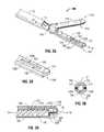
Referring now toFIGS. 2A-2B , eachjaw member end effector assembly 100 includes an electrically conductivetissue sealing surface outer jaw housing Jaw member 120 includes achannel 130 defined therein and extending longitudinally therealong.Channel 130 bisects sealingsurface 122 ofjaw member 120, dividing sealingsurface 122 into sealingsurface sections Channel 130 extends along a substantial length ofjaw member 120 and may be centered about a longitudinal axis “X-X” ofjaw member 120. A cuttingassembly 150 including a cuttingmember 152 is operably coupled tojaw member 120. Cuttingmember 152 is positioned withinchannel 130 and is rotatable with respect tojaw member 120 about longitudinal axis “X-X” ofjaw member 120.
More specifically, and with reference toFIGS. 3A-5 , cuttingassembly 150 includes a cuttingmember 152 having alumen 154 extending therethrough, arotating bar 156 configured to fixedly engage cuttingmember 152 throughlumen 154, and one ormore drive components 158 that are coupled to rotatingbar 156 to rotaterotating bar 156 with respect tojaw member 120, thereby rotating cuttingmember 152 with respect tojaw member 120. One or morelead wires 160 extend through shaft12 (FIG. 1 ) and are coupled to drive component(s)158 for providing power to electrically or electro-mechanically rotate cuttingmember 152 about longitudinal axis “X-X.”
As shown inFIGS. 3A-3B , and as mentioned above, cylindrical cuttingmember 152 is positioned withinchannel 130.Channel 130 is configured to seat cuttingmember 152 therein. More specifically, the length and width ofchannel 130 are greater than the length and width of cuttingmember 152 such that cuttingmember 152 may be positioned at least partially withinchannel 130. However,channel 130 may define a depth less than the diameter of cylindrical cuttingmember 152 such that at least a portion of cuttingmember 152 protrudes fromchannel 130, e.g., such that cuttingmember 152 extends from between sealingsurface sections jaw member 110 when cuttingmember 152 is positioned withinchannel 130.
As best shown inFIG. 3A ,jaw member 110 may include a complementary recessed portion, orchannel 118 defined therein and configured to accommodate cuttingmember 152 upon approximation ofjaw members jaw members member 152 protruding fromchannel 130 is positioned withinchannel 118, permittingjaw members member 152 andchannel 130 may be configured such that cuttingmember 152 protrudes only slightly from channel130 a distance smaller than the gap distance “G” betweenjaw members jaw member jaw member 110 to permit full approximation ofjaw members jaw member member 152 is positioned adjacent, but not in contact with sealingsurface 112 ofjaw member 110.
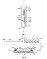
With reference now toFIGS. 4-5 , rotatingbar 156 of cuttingassembly 150 is fixedly engaged withinlumen 154 of cuttingmember 152, e.g., via adhesion, welding, friction-fitting, etc. Rotatingbar 156 defines a length greater than the length of cuttingmember 152 such that when rotatingbar 156 is disposed throughlumen 154, rotatingbar 154 protrudes from both ends oflumen 154. More particularly,distal end 156aofrotating bar 156 protrudes fromdistal end 152aof cuttingmember 152 whileproximal end 156bof rotatingbar 156 protrudes fromproximal end 152bof rotatingbar 152. Alternatively, instead of rotatingbar 156 being operably disposed throughlumen 154 of cuttingmember 152 and protruding therefrom, rotatingbar 156 may include two disconnected ends, adistal end 156athat is fixedly-engaged todistal end 152aof cuttingmember 152 and aproximal end 156bthat is fixedly-engaged toproximal end 152bof cuttingmember 152. In such an embodiment, cuttingmember 152 may be solid, i.e., cuttingmember 152 need not have a lumen defined therethrough. Further, rotatingbar 156 and cuttingmember 152 may be engaged via any other suitable mechanism wherein rotatingbar 156 is fixedly-engaged to cuttingmember 152 and such that distal and proximal ends156a,156b, respectively, of rotatingbar 156 protrude from respective distal and proximal ends152a,152bof cuttingmember 152.
With continued reference toFIGS. 4-5 , adistal end 132 ofchannel 130 includes anaperture 133 defined therethrough.Aperture 133 is configured to receivedistal end 156aofrotating bar 156 therein. Similarly, aproximal end 134 ofchannel 130 includes anaperture 135 defined therethrough and configured to receiveproximal end 156bof rotatingbar 156. During assembly, as best shown inFIG. 5 , rotatingbar 156 is engaged withinlumen 154 of cuttingmember 152 anddistal end 156aofrotating bar 156 is inserted throughaperture 133 atdistal end 132 ofchannel 130 whileproximal end 156bof rotatingbar 156 is inserted throughaperture 135 atproximal end 134 ofchannel 130 to securely suspend cuttingmember 130 withinchannel 130.Apertures jaw member 120 such that, when cuttingmember 152 is engaged withinjaw member 120, cuttingmember 152 is centered with respect to longitudinal axis “X-X.”Apertures bar 156 when rotatingbar 156 is disposed therethrough.
A drive component158 (or drive components158) is disposed withinjaw member 120 at one (or both) end132 and/or134 ofchannel 130. As mentioned above, distal and/or proximal ends156a,156b, respectively, of rotatingbar 156 extend throughapertures bar 156, thereby rotating cuttingmember 152 with respect tojaw member 120. Leadwires 160 provide power to drive component(s)158 and, thus, activate and/or deactivate drive component(s)158. More specifically,lead wires 160 extend from drive component(s)158, through shaft12 (FIG. 1 ), and ultimately connect to an energy source, e.g., a battery (not shown) disposed withinhandle assembly 20 or a cable, e.g.,cable 310, which is connected to an external source of energy, e.g., a generator (not shown).
Further, another oflead wires 160 may be coupled to an actuator, or trigger, e.g., trigger70 (FIG. 1 ) for activating drive component(s)158. In other words, when a user depresses trigger70 (FIG. 1 ),lead wires 160 communicate energy to drive component(s)158, activating drive component(s)158 to, in turn, rotate cuttingmember 152 about longitudinal axis “X-X” ofjaw member 120. As can be appreciated, whentrigger 70 is released, energy is no longer supplied to drive component(s)158 and, thus, drive component(s)158 is deactivated, no longer driving the rotation of cuttingmember 152.
Alternatively, any other suitablerotatable cutting assembly 150 positionable within one (or both) ofjaw members member 152 with respect tojaw member 120.
Referring once again toFIGS. 3A-5 , elongatedcylindrical cutting member 152 may include a plurality oftextured elements 172 disposed on an outer peripheral, orexternal surface 170 thereof.Textured elements 172 may besharp barbs 172 positioned helically about cuttingmember 152, as shown inFIGS. 3A-5 . However,textured elements 172 may alternatively be raised, recessed, or rough textured features defined onexternal surface 170 of cuttingmember 152. Further,textured elements 172 may be positioned in any suitable configuration onexternal surface 170 of cuttingmember 152. As will be described in greater detail below,textured elements 172 facilitate cutting of tissue disposed betweenjaw members member 152 with respect to tissue.
The operation offorceps 10 will now be described with reference toFIGS. 1-5 .Forceps 10 may be adapted for use in endoscopic procedures as well as in open surgical procedures. The configuration offorceps 10 is particularly advantageous for use in laparoscopic or endoscopic procedures due to the relatively small-diametered, elongated dimensions ofshaft 12 andend effector assembly 100. More particularly, since cuttingassembly 150 is completely disposed withinjaw member 120 ofend effector assembly 100,shaft 12 need not be configured to house additional components therein, e.g., a cutting mechanism. Eliminating the cutting mechanism or drive rods associated therewith fromshaft 12 allowsshaft 12 to define a reduced diameter. Further, positioning the cuttingassembly 150 completely withinjaw member 120 allowsend effector assembly 100 to be rotated with respect tohousing 20, e.g., via rotating the rotating assembly80 (FIG. 1 ), without requiring repositioning or articulating of cuttingassembly 150 with respect tojaw members forceps 10, having a reduced diameter and simplified maneuverability, may be inserted through relatively smaller incisions in tissue, allowing for quicker recovery time and reduced patient discomfort.
In use, as shown inFIG. 2 ,forceps 10 is initially positioned such that tissue to be sealed and/or cut is disposed betweenjaw members end effector assembly 100 may be rotated about longitudinal axis “X-X” to positionjaw members FIG. 1 ) is translated, i.e., squeezed, toward fixedhandle 50 to movejaw members surfaces respective jaw members member 152 of cuttingassembly 150 remains un-actuated, or stationary with respect tojaw member 120. Although cuttingmember 152 may include exposed textured elements, e.g.,barbs 172, tissue grasped betweenjaw members member 152 remains stationary with respect to tissue grasped betweenjaw members surfaces 112 and/or122 for sealing tissue disposed therebetween. Accordingly, a tissue seal may be effected substantially along a width of sealingsurfaces jaw members
With tissue grasped between sealingsurfaces assembly 150 may be activated to cut tissue, e.g., along the tissue seal. More specifically, trigger70 (FIG. 1 ) may be depressed, or actuated to communicate energy throughlead wires 160 to activate drive component(s)158. When activated, the electrical or electromechanical drive component(s)158, as mentioned above, drives the rotation of rotatingbar 156 and, thus, cuttingmember 152, with respect tojaw member 120 about longitudinal axis “X-X” (as shown by arrows “Z” inFIG. 3B ). Since tissue is clamped betweenjaw members member 152 is also rotated with respect to tissue.
As cuttingmember 152 is rotated with respect to tissue, friction is created at the interface betweenexternal surface 170 of cuttingmember 152 and tissue, asexternal surface 170 is rotated relative to tissue. Drive component(s)158 may be configured to rotate cuttingmember 152 at a sufficient rate so as to produce enough friction to create a cutting effect. Thus, when cuttingmember 152 is rotated at a sufficient rate, cuttingmember 152 frictionally dissects the previously sealed tissue disposed betweenjaw members FIG. 1 ) may be selectively depressible to increase and/or decrease the rotational speed of cuttingmember 152. As can be appreciated, the rotational speed required to sever a particular portion of tissue grasped betweenjaw members trigger 70 allows a user to provide enough rotational speed to dissect through the particular size and/or composition of tissue disposed betweenjaw members
Cuttingassembly 150 may also include a locking mechanism (not shown) for inhibiting rotation of cuttingmember 152 with respect tojaw member 120 whenjaw members assembly 150. The locking mechanism (not shown) may be automatic, inhibiting cuttingassembly 150 from being activated whilejaw members assembly 150 is biased toward a locked position whenjaw members assembly 150 to dissect tissue whenjaw members
From the foregoing and with reference to the various figure drawings, those skilled in the art will appreciate that certain modifications can also be made to the present disclosure without departing from the scope of the same. While several embodiments of the disclosure have been shown in the drawings, it is not intended that the disclosure be limited thereto, as it is intended that the disclosure be as broad in scope as the art will allow and that the specification be read likewise. Therefore, the above description should not be construed as limiting, but merely as exemplifications of particular embodiments. Those skilled in the art will envision other modifications within the scope and spirit of the claims appended hereto.
Claims (11)
1. A forceps, comprising:
a housing having a shaft attached thereto and an end effector assembly disposed at a distal end of the shaft, the end effector assembly including:
first and second jaw members defining electrically-conductive surfaces disposed in opposed relation relative to one another, at least one of the jaw members being moveable with respect to the other between a spaced-apart position and an approximated position for grasping tissue between the electrically-conductive surfaces, the first jaw member defining a cavity extending through and surrounded by the electrically-conductive surface of the first jaw member, at least one of the electrically-conductive surfaces adapted to connect to a source of energy for conducting energy through tissue grasped between the electrically-conductive surfaces to treat tissue on either side of the cavity; and
a cutting assembly including a cutting member disposed within the cavity and rotatably coupled to the first jaw member, the cutting member configured to rotate with respect to the first jaw member about a longitudinal axis thereof to cut tissue between treated portions of tissue.
2. The forceps according toclaim 1 , wherein the cutting member is positioned within the first jaw member and extends longitudinally therealong, the cutting member configured to rotate about a rod disposed therethrough to cut tissue disposed between the jaw members.
3. The forceps according toclaim 1 , wherein the cutting member includes a textured surface disposed on an outer peripheral surface thereof.
4. The forceps according toclaim 3 , wherein the cutting member includes a plurality of textured barbs positioned on the outer periphery thereof that are configured to engaged tissue during rotation thereof.
5. The forceps according toclaim 1 , wherein the cutting member defines a circular front cross-sectional configuration.
6. The forceps according toclaim 1 , wherein at least one drive component is disposed within the first jaw member, the at least one drive component configured for one of electrically and electromechanically driving rotation of the cutting member with respect to the first jaw member.
7. An end effector assembly for use with a forceps, the end effector assembly comprising:
first and second jaw members defining electrically-conductive surfaces disposed in opposed relation relative to one another, at least one of the jaw members being moveable with respect to the other between a spaced-apart position and an approximated position for grasping tissue between the electrically-conductive surfaces, the first jaw member defining a cavity extending through and surrounded by the electrically-conductive surface of the first jaw member, at least one of the electrically-conductive surfaces adapted to connect to a source of energy for conducting energy through tissue grasped between the electrically-conductive surfaces to treat tissue on either side of the cavity; and
an elongated cutting member positioned within the cavity and extending longitudinally therealong, the elongated cutting member rotatably coupled to the first jaw member and rotatable with respect to a longitudinal axis of the first jaw member to cut tissue between treated portions of tissue.
8. The end effector assembly according toclaim 7 , wherein the cutting member defines a circular front cross-sectional configuration.
9. The forceps according toclaim 7 , wherein an outer peripheral surface of the cutting member is configured to frictionally engage tissue during rotation thereof.
10. The forceps according toclaim 7 , wherein the cutting member includes a plurality of textured barbs positioned on an outer peripheral surface thereof that are configured to engaged tissue during rotation thereof.
11. The end effector assembly according toclaim 7 , wherein, at least one drive component is disposed within the first jaw member, the at least one drive component configured for one of electrically and electromechanically driving the rotation of the elongated cutting member with respect to the first jaw member.
Priority Applications (1)
| Application Number | Priority Date | Filing Date | Title |
|---|---|---|---|
| US12/861,209US8652135B2 (en) | 2010-08-23 | 2010-08-23 | Surgical forceps |
Applications Claiming Priority (1)
| Application Number | Priority Date | Filing Date | Title |
|---|---|---|---|
| US12/861,209US8652135B2 (en) | 2010-08-23 | 2010-08-23 | Surgical forceps |
Publications (2)
| Publication Number | Publication Date |
|---|---|
| US20120046660A1 US20120046660A1 (en) | 2012-02-23 |
| US8652135B2true US8652135B2 (en) | 2014-02-18 |
Family
ID=45594651
Family Applications (1)
| Application Number | Title | Priority Date | Filing Date |
|---|---|---|---|
| US12/861,209Active2032-10-23US8652135B2 (en) | 2010-08-23 | 2010-08-23 | Surgical forceps |
Country Status (1)
| Country | Link |
|---|---|
| US (1) | US8652135B2 (en) |
Cited By (42)
| Publication number | Priority date | Publication date | Assignee | Title |
|---|---|---|---|---|
| US8795269B2 (en) | 2010-07-26 | 2014-08-05 | Covidien Lp | Rotary tissue sealer and divider |
| US9005200B2 (en) | 2010-09-30 | 2015-04-14 | Covidien Lp | Vessel sealing instrument |
| US9028495B2 (en) | 2010-06-23 | 2015-05-12 | Covidien Lp | Surgical instrument with a separable coaxial joint |
| US9113908B2 (en) | 2011-09-16 | 2015-08-25 | Covidien Lp | Seal plate with insulation displacement connection |
| USD750245S1 (en)* | 2012-03-08 | 2016-02-23 | Covidien Lp | Handle for laparoscopic device with integral rotation wheel |
| US9375229B2 (en) | 2011-01-14 | 2016-06-28 | Covidien Lp | Latch mechanism for surgical instruments |
| US9498279B2 (en) | 2010-10-04 | 2016-11-22 | Covidien Lp | Vessel sealing instrument |
| US9526567B2 (en) | 2011-05-16 | 2016-12-27 | Covidien Lp | Thread-like knife for tissue cutting |
| US9579145B2 (en) | 2005-09-30 | 2017-02-28 | Covidien Ag | Flexible endoscopic catheter with ligasure |
| US9649121B2 (en) | 2011-05-19 | 2017-05-16 | Covidien Lp | Apparatus for performing an electrosurgical procedure |
| US9668808B2 (en) | 2011-05-06 | 2017-06-06 | Covidien Lp | Bifurcated shaft for surgical instrument |
| US9707031B2 (en) | 2011-07-11 | 2017-07-18 | Covidien Lp | Surgical forceps and method of manufacturing thereof |
| US9724157B2 (en) | 2011-08-09 | 2017-08-08 | Covidien Lp | Microwave sensing for tissue sealing |
| US9814518B2 (en) | 2010-09-08 | 2017-11-14 | Covidien Lp | Asymmetrical electrodes for bipolar vessel sealing |
| US9848938B2 (en) | 2003-11-13 | 2017-12-26 | Covidien Ag | Compressible jaw configuration with bipolar RF output electrodes for soft tissue fusion |
| US9867657B2 (en) | 2011-05-06 | 2018-01-16 | Covidien Lp | Surgical forceps |
| US9867654B2 (en) | 2010-11-17 | 2018-01-16 | Covidien Lp | Method and apparatus for vascular tissue sealing with reduced energy consumption |
| USD843574S1 (en) | 2017-06-08 | 2019-03-19 | Covidien Lp | Knife for open vessel sealer |
| USD854149S1 (en) | 2017-06-08 | 2019-07-16 | Covidien Lp | End effector for open vessel sealer |
| USD854684S1 (en) | 2017-06-08 | 2019-07-23 | Covidien Lp | Open vessel sealer with mechanical cutter |
| US10426543B2 (en) | 2016-01-23 | 2019-10-01 | Covidien Lp | Knife trigger for vessel sealer |
| US10575865B2 (en) | 2011-07-11 | 2020-03-03 | Covidien Lp | Surgical forceps |
| US10631887B2 (en) | 2016-08-15 | 2020-04-28 | Covidien Lp | Electrosurgical forceps for video assisted thoracoscopic surgery and other surgical procedures |
| US10682154B2 (en) | 2016-08-02 | 2020-06-16 | Covidien Lp | Cutting mechanisms for surgical end effector assemblies, instruments, and systems |
| USD888951S1 (en)* | 2018-11-15 | 2020-06-30 | Ethicon Llc | Pair of bipolar electrosurgical jaws |
| USD904611S1 (en) | 2018-10-10 | 2020-12-08 | Bolder Surgical, Llc | Jaw design for a surgical instrument |
| US10869682B2 (en) | 2016-07-08 | 2020-12-22 | Covidien Lp | Cutting mechanisms for surgical end effector assemblies, instruments, and systems |
| US10939953B2 (en)* | 2015-03-23 | 2021-03-09 | Gyrus Acmi, Inc. | Medical forceps with vessel transection capability |
| US10959770B2 (en) | 2013-08-07 | 2021-03-30 | Covidien Lp | Method of assembling an electrosurgical instrument |
| US10973567B2 (en) | 2017-05-12 | 2021-04-13 | Covidien Lp | Electrosurgical forceps for grasping, treating, and/or dividing tissue |
| US10980557B2 (en) | 2010-10-01 | 2021-04-20 | Covidien Lp | Blade deployment mechanisms for surgical forceps |
| US10987159B2 (en) | 2015-08-26 | 2021-04-27 | Covidien Lp | Electrosurgical end effector assemblies and electrosurgical forceps configured to reduce thermal spread |
| US11076907B2 (en) | 2011-06-17 | 2021-08-03 | Covidien Lp | Tissue sealing forceps |
| US11172980B2 (en) | 2017-05-12 | 2021-11-16 | Covidien Lp | Electrosurgical forceps for grasping, treating, and/or dividing tissue |
| US11350982B2 (en) | 2018-12-05 | 2022-06-07 | Covidien Lp | Electrosurgical forceps |
| US11376062B2 (en) | 2018-10-12 | 2022-07-05 | Covidien Lp | Electrosurgical forceps |
| US11471211B2 (en) | 2018-10-12 | 2022-10-18 | Covidien Lp | Electrosurgical forceps |
| US11523861B2 (en) | 2019-03-22 | 2022-12-13 | Covidien Lp | Methods for manufacturing a jaw assembly for an electrosurgical forceps |
| US11628008B2 (en) | 2020-03-16 | 2023-04-18 | Covidien Lp | Forceps with linear trigger kickout mechanism |
| US11660109B2 (en) | 2020-09-08 | 2023-05-30 | Covidien Lp | Cutting elements for surgical instruments such as for use in robotic surgical systems |
| US12295641B2 (en) | 2020-07-01 | 2025-05-13 | Covidien Lp | Electrosurgical forceps with swivel action nerve probe |
| US12402934B2 (en) | 2019-09-15 | 2025-09-02 | Covidien Lp | Electrosurgical instrument for grasping, treating, and/or dividing tissue incorporating thermal management feature |
Families Citing this family (16)
| Publication number | Priority date | Publication date | Assignee | Title |
|---|---|---|---|---|
| US7364577B2 (en) | 2002-02-11 | 2008-04-29 | Sherwood Services Ag | Vessel sealing system |
| ES2262639T3 (en) | 2001-04-06 | 2006-12-01 | Sherwood Services Ag | SHUTTER AND DIVIDER OF GLASSES WITH BUMPER MEMBERS N OCONDUCTIVES. |
| US7367976B2 (en) | 2003-11-17 | 2008-05-06 | Sherwood Services Ag | Bipolar forceps having monopolar extension |
| US7628791B2 (en) | 2005-08-19 | 2009-12-08 | Covidien Ag | Single action tissue sealer |
| US8142473B2 (en) | 2008-10-03 | 2012-03-27 | Tyco Healthcare Group Lp | Method of transferring rotational motion in an articulating surgical instrument |
| US8187273B2 (en) | 2009-05-07 | 2012-05-29 | Tyco Healthcare Group Lp | Apparatus, system, and method for performing an electrosurgical procedure |
| US8246618B2 (en) | 2009-07-08 | 2012-08-21 | Tyco Healthcare Group Lp | Electrosurgical jaws with offset knife |
| US8133254B2 (en) | 2009-09-18 | 2012-03-13 | Tyco Healthcare Group Lp | In vivo attachable and detachable end effector assembly and laparoscopic surgical instrument and methods therefor |
| US8112871B2 (en) | 2009-09-28 | 2012-02-14 | Tyco Healthcare Group Lp | Method for manufacturing electrosurgical seal plates |
| US8814864B2 (en) | 2010-08-23 | 2014-08-26 | Covidien Lp | Method of manufacturing tissue sealing electrodes |
| US9113940B2 (en) | 2011-01-14 | 2015-08-25 | Covidien Lp | Trigger lockout and kickback mechanism for surgical instruments |
| USD680220S1 (en) | 2012-01-12 | 2013-04-16 | Coviden IP | Slider handle for laparoscopic device |
| US9192421B2 (en) | 2012-07-24 | 2015-11-24 | Covidien Lp | Blade lockout mechanism for surgical forceps |
| US11331144B2 (en)* | 2018-05-04 | 2022-05-17 | Covidien Lp | Light energy surgical system, apparatus, and method |
| US20230056953A1 (en)* | 2020-01-30 | 2023-02-23 | Covidien Lp | Surgical instruments having a rotatable blade member for treating tissue |
| CN115209821A (en)* | 2020-03-04 | 2022-10-18 | 柯惠有限合伙公司 | Surgical instrument with movable blade member for treating tissue |
Citations (105)
| Publication number | Priority date | Publication date | Assignee | Title |
|---|---|---|---|---|
| SU401367A1 (en) | 1971-10-05 | 1973-10-12 | Тернопольский государственный медицинский институт | BIAKTIVNYE ELECTRO SURGICAL INSTRUMENT |
| DE2415263A1 (en) | 1974-03-29 | 1975-10-02 | Aesculap Werke Ag | Surgical H.F. coagulation probe has electrode tongs - with exposed ends of insulated conductors forming tong-jaws |
| DE2514501A1 (en) | 1975-04-03 | 1976-10-21 | Karl Storz | Bipolar coagulation instrument for endoscopes - has two high frequency electrodes looped over central insulating piece |
| DE2627679A1 (en) | 1975-06-26 | 1977-01-13 | Marcel Lamidey | HEMATISTIC HIGH FREQUENCY EXTRACTOR FORCEPS |
| USD249549S (en) | 1976-10-22 | 1978-09-19 | Aspen Laboratories, Inc. | Electrosurgical handle |
| USD263020S (en) | 1980-01-22 | 1982-02-16 | Rau Iii David M | Retractable knife |
| DE3423356A1 (en) | 1984-06-25 | 1986-01-02 | Berchtold Medizin-Elektronik GmbH & Co, 7200 Tuttlingen | ELECTROSURGICAL HIGH-FREQUENCY CUTTING INSTRUMENT |
| JPS61501068A (en) | 1984-01-30 | 1986-05-29 | ハルコフスキイ ナウチノ−イススレドワテルスキイ インスチチユ−ト オブスチエイ イ ネオトロジノイ ヒルルギイ | bipolar electrosurgical instrument |
| DE3612646A1 (en) | 1985-04-16 | 1987-04-30 | Ellman International | Electrosurgical handle piece for blades, needles and forceps |
| DE8712328U1 (en) | 1987-09-11 | 1988-02-18 | Jakoubek, Franz, 7201 Emmingen-Liptingen | Endoscopy forceps |
| USD295894S (en) | 1985-09-26 | 1988-05-24 | Acme United Corporation | Disposable surgical scissors |
| USD295893S (en) | 1985-09-25 | 1988-05-24 | Acme United Corporation | Disposable surgical clamp |
| USD298353S (en) | 1986-05-06 | 1988-11-01 | Vitalmetrics, Inc. | Handle for surgical instrument |
| USD299413S (en) | 1985-07-17 | 1989-01-17 | The Stanley Works | Folding pocket saw handle |
| JPH055106A (en) | 1990-07-31 | 1993-01-14 | Matsushita Electric Works Ltd | Production of alloy sintered body |
| JPH0540112A (en) | 1991-02-08 | 1993-02-19 | Tokico Ltd | Sample liquid component analyzer |
| USD343453S (en) | 1993-05-05 | 1994-01-18 | Laparomed Corporation | Handle for laparoscopic surgical instrument |
| JPH06502328A (en) | 1990-10-17 | 1994-03-17 | ボストン サイエンティフィック コーポレイション | Surgical instruments and methods |
| USD348930S (en) | 1991-10-11 | 1994-07-19 | Ethicon, Inc. | Endoscopic stapler |
| USD349341S (en) | 1992-10-28 | 1994-08-02 | Microsurge, Inc. | Endoscopic grasper |
| DE4303882A1 (en) | 1993-02-10 | 1994-08-18 | Kernforschungsz Karlsruhe | Combined instrument for separating and coagulating in minimally invasive surgery |
| JPH06343644A (en) | 1993-05-04 | 1994-12-20 | Gyrus Medical Ltd | Surgical peritoneoscope equipment |
| USD354564S (en) | 1993-06-25 | 1995-01-17 | Richard-Allan Medical Industries, Inc. | Surgical clip applier |
| USD358887S (en) | 1993-12-02 | 1995-05-30 | Cobot Medical Corporation | Combined cutting and coagulating forceps |
| DE4403252A1 (en) | 1994-02-03 | 1995-08-10 | Michael Hauser | Instrument shaft for min. invasive surgery |
| US5456689A (en) | 1993-10-13 | 1995-10-10 | Arnold J. Kresch | Method and device for tissue resection |
| JPH07265328A (en) | 1993-11-01 | 1995-10-17 | Gyrus Medical Ltd | Electrode assembly for electric surgery device and electric surgery device using it |
| JPH0856955A (en) | 1994-06-29 | 1996-03-05 | Gyrus Medical Ltd | Electric surgical apparatus |
| US5509923A (en) | 1989-08-16 | 1996-04-23 | Raychem Corporation | Device for dissecting, grasping, or cutting an object |
| DE19515914C1 (en) | 1995-05-02 | 1996-07-25 | Aesculap Ag | Tong or scissor-shaped surgical instrument |
| US5540706A (en) | 1993-01-25 | 1996-07-30 | Aust; Gilbert M. | Surgical instrument |
| DE19506363A1 (en) | 1995-02-24 | 1996-08-29 | Frost Lore Geb Haupt | Non-invasive thermometry in organs under hyperthermia and coagulation conditions |
| JPH08252263A (en) | 1994-12-21 | 1996-10-01 | Gyrus Medical Ltd | Electronic surgical incision instrument and electronic surgical incision device using the same |
| US5569284A (en)* | 1994-09-23 | 1996-10-29 | United States Surgical Corporation | Morcellator |
| DE29616210U1 (en) | 1996-09-18 | 1996-11-14 | Olympus Winter & Ibe Gmbh, 22045 Hamburg | Handle for surgical instruments |
| JPH0910223A (en) | 1995-06-23 | 1997-01-14 | Gyrus Medical Ltd | Generator and system for electric operation |
| DE19608716C1 (en) | 1996-03-06 | 1997-04-17 | Aesculap Ag | Bipolar surgical holding instrument |
| USD384413S (en) | 1994-10-07 | 1997-09-30 | United States Surgical Corporation | Endoscopic suturing instrument |
| JPH1024051A (en) | 1995-09-20 | 1998-01-27 | Olympus Optical Co Ltd | Coagulation forceps with separating function |
| DE19751106A1 (en) | 1996-11-27 | 1998-05-28 | Eastman Kodak Co | Laser printer with array of laser diodes |
| US5810805A (en)* | 1996-02-09 | 1998-09-22 | Conmed Corporation | Bipolar surgical devices and surgical methods |
| USD402028S (en) | 1997-10-10 | 1998-12-01 | Invasatec, Inc. | Hand controller for medical system |
| DE19738457A1 (en) | 1997-09-03 | 1999-03-04 | Laser & Med Tech Gmbh | Method for in-vivo depth coagulation of biological tissue |
| JPH1170124A (en) | 1997-05-14 | 1999-03-16 | Ethicon Endo Surgery Inc | Improved electrosurgical hemostatic apparatus having anvil |
| DE19751108A1 (en) | 1997-11-18 | 1999-05-20 | Beger Frank Michael Dipl Desig | Electrosurgical operation tool, especially for diathermy |
| JPH11169381A (en) | 1997-12-15 | 1999-06-29 | Olympus Optical Co Ltd | High frequency treating device |
| JPH11244298A (en) | 1997-12-19 | 1999-09-14 | Gyrus Medical Ltd | Electric surgical instrument |
| USD416089S (en) | 1996-04-08 | 1999-11-02 | Richard-Allan Medical Industries, Inc. | Endoscopic linear stapling and dividing surgical instrument |
| US6017340A (en) | 1994-10-03 | 2000-01-25 | Wiltek Medical Inc. | Pre-curved wire guided papillotome having a shape memory tip for controlled bending and orientation |
| JP2000102545A (en) | 1997-06-18 | 2000-04-11 | Eggers & Associates Inc | Electric tweezers for surgery |
| USD424694S (en) | 1998-10-23 | 2000-05-09 | Sherwood Services Ag | Forceps |
| USD425201S (en) | 1998-10-23 | 2000-05-16 | Sherwood Services Ag | Disposable electrode assembly |
| JP2000342599A (en) | 1999-05-21 | 2000-12-12 | Gyrus Medical Ltd | Generator for electrosurgical operation, electrosurgical operation system, method for operating this system and method for performing amputation and resection of tissue by electrosurgical operation |
| JP2000350732A (en) | 1999-05-21 | 2000-12-19 | Gyrus Medical Ltd | Electrosurgical system, generator for electrosurgery, and method for cutting or excising tissue by electrosurgery |
| JP2001008944A (en) | 1999-05-28 | 2001-01-16 | Gyrus Medical Ltd | Electric surgical signal generator and electric surgical system |
| JP2001029356A (en) | 1999-06-11 | 2001-02-06 | Gyrus Medical Ltd | Electric and surgical signal generator |
| JP2001128990A (en) | 1999-05-28 | 2001-05-15 | Gyrus Medical Ltd | Electro surgical instrument and electrosurgical tool converter |
| USD449886S1 (en) | 1998-10-23 | 2001-10-30 | Sherwood Services Ag | Forceps with disposable electrode |
| EP1159926A2 (en) | 2000-06-03 | 2001-12-05 | Aesculap Ag | Scissor- or forceps-like surgical instrument |
| USD454951S1 (en) | 2001-02-27 | 2002-03-26 | Visionary Biomedical, Inc. | Steerable catheter |
| DE10045375A1 (en) | 2000-09-14 | 2002-04-11 | Aesculap Ag & Co Kg | Medical instrument comprises temperature and pressure condition sensor and modification device for influencing transmitting device |
| USD457958S1 (en) | 2001-04-06 | 2002-05-28 | Sherwood Services Ag | Vessel sealer and divider |
| USD457959S1 (en) | 2001-04-06 | 2002-05-28 | Sherwood Services Ag | Vessel sealer |
| US6398741B2 (en) | 1998-11-20 | 2002-06-04 | J. Morita Manufacturing Corporation | Tissue excision and cutting apparatus and its forceps |
| USD465281S1 (en) | 1999-09-21 | 2002-11-05 | Karl Storz Gmbh & Co. Kg | Endoscopic medical instrument |
| USD466209S1 (en) | 2001-02-27 | 2002-11-26 | Visionary Biomedical, Inc. | Steerable catheter |
| US20030018332A1 (en) | 2001-06-20 | 2003-01-23 | Schmaltz Dale Francis | Bipolar electrosurgical instrument with replaceable electrodes |
| US20040102804A1 (en) | 1999-08-10 | 2004-05-27 | Chin Albert K. | Apparatus and methods for endoscopic surgical procedures |
| USD493888S1 (en) | 2003-02-04 | 2004-08-03 | Sherwood Services Ag | Electrosurgical pencil with pistol grip |
| USD496997S1 (en) | 2003-05-15 | 2004-10-05 | Sherwood Services Ag | Vessel sealer and divider |
| USD499181S1 (en) | 2003-05-15 | 2004-11-30 | Sherwood Services Ag | Handle for a vessel sealer and divider |
| US6860880B2 (en) | 1997-03-05 | 2005-03-01 | The Trustees Of Columbia University In The City Of New York | Electrothermal instrument for sealing and joining or cutting tissue |
| USD502994S1 (en) | 2003-05-21 | 2005-03-15 | Blake, Iii Joseph W | Repeating multi-clip applier |
| USD509297S1 (en) | 2003-10-17 | 2005-09-06 | Tyco Healthcare Group, Lp | Surgical instrument |
| DE102004026179A1 (en) | 2004-05-14 | 2005-12-08 | Erbe Elektromedizin Gmbh | Electrosurgical instrument |
| USD525361S1 (en) | 2004-10-06 | 2006-07-18 | Sherwood Services Ag | Hemostat style elongated dissecting and dividing instrument |
| US20060167450A1 (en)* | 2005-01-14 | 2006-07-27 | Johnson Kristin D | Vessel sealer and divider with rotating sealer and cutter |
| USD531311S1 (en) | 2004-10-06 | 2006-10-31 | Sherwood Services Ag | Pistol grip style elongated dissecting and dividing instrument |
| USD533274S1 (en) | 2004-10-12 | 2006-12-05 | Allegiance Corporation | Handle for surgical suction-irrigation device |
| USD533942S1 (en) | 2004-06-30 | 2006-12-19 | Sherwood Services Ag | Open vessel sealer with mechanical cutter |
| USD535027S1 (en) | 2004-10-06 | 2007-01-09 | Sherwood Services Ag | Low profile vessel sealing and cutting mechanism |
| USD538932S1 (en) | 2005-06-30 | 2007-03-20 | Medical Action Industries Inc. | Surgical needle holder |
| USD541418S1 (en) | 2004-10-06 | 2007-04-24 | Sherwood Services Ag | Lung sealing device |
| USD541938S1 (en) | 2004-04-09 | 2007-05-01 | Sherwood Services Ag | Open vessel sealer with mechanical cutter |
| USD541611S1 (en) | 2006-01-26 | 2007-05-01 | Robert Bosch Gmbh | Cordless screwdriver |
| USD545432S1 (en) | 2003-08-08 | 2007-06-26 | Olympus Corporation | Distal portion of hemostatic forceps for endoscope |
| USD547154S1 (en) | 2006-09-08 | 2007-07-24 | Winsource Industries Limited | Rotary driving tool |
| DE202007009317U1 (en) | 2007-06-26 | 2007-08-30 | Aesculap Ag & Co. Kg | Surgical instrument |
| USD564662S1 (en) | 2004-10-13 | 2008-03-18 | Sherwood Services Ag | Hourglass-shaped knife for electrosurgical forceps |
| USD567943S1 (en) | 2004-10-08 | 2008-04-29 | Sherwood Services Ag | Over-ratchet safety for a vessel sealing instrument |
| USD575401S1 (en) | 2007-06-12 | 2008-08-19 | Tyco Healthcare Group Lp | Vessel sealer |
| USD575395S1 (en) | 2007-02-15 | 2008-08-19 | Tyco Healthcare Group Lp | Hemostat style elongated dissecting and dividing instrument |
| USD582038S1 (en) | 2004-10-13 | 2008-12-02 | Medtronic, Inc. | Transurethral needle ablation device |
| USD617900S1 (en) | 2009-05-13 | 2010-06-15 | Tyco Healthcare Group Lp | End effector tip with undercut bottom jaw |
| USD617902S1 (en) | 2009-05-13 | 2010-06-15 | Tyco Healthcare Group Lp | End effector tip with undercut top jaw |
| USD617903S1 (en) | 2009-05-13 | 2010-06-15 | Tyco Healthcare Group Lp | End effector pointed tip |
| USD617901S1 (en) | 2009-05-13 | 2010-06-15 | Tyco Healthcare Group Lp | End effector chamfered tip |
| USD618798S1 (en) | 2009-05-13 | 2010-06-29 | Tyco Healthcare Group Lp | Vessel sealing jaw seal plate |
| USD621503S1 (en) | 2009-04-28 | 2010-08-10 | Tyco Healthcare Group Ip | Pistol grip laparoscopic sealing and dissection device |
| US20100204697A1 (en) | 2005-09-30 | 2010-08-12 | Dumbauld Patrick L | In-Line Vessel Sealer and Divider |
| US20100204698A1 (en) | 2003-05-01 | 2010-08-12 | Chapman Troy J | Incorporating Rapid Cooling in Tissue Fusion Heating Processes |
| US20100217258A1 (en) | 2007-06-29 | 2010-08-26 | Tyco Healthcare Group ,LP | Method and system for monitoring tissue during an electrosurgical procedure |
| US20100249776A1 (en) | 2009-03-26 | 2010-09-30 | Tyco Healthcare Group Lp | Apparatus, System, and Method for Performing an Endoscopic Electrosurgical Procedure |
| US20100249769A1 (en) | 2009-03-24 | 2010-09-30 | Tyco Healthcare Group Lp | Apparatus for Tissue Sealing |
| US8100906B2 (en)* | 2005-03-24 | 2012-01-24 | Erbe Elektromedizin Gmbh | Electrosurgical instrument |
- 2010
- 2010-08-23USUS12/861,209patent/US8652135B2/enactiveActive
Patent Citations (105)
| Publication number | Priority date | Publication date | Assignee | Title |
|---|---|---|---|---|
| SU401367A1 (en) | 1971-10-05 | 1973-10-12 | Тернопольский государственный медицинский институт | BIAKTIVNYE ELECTRO SURGICAL INSTRUMENT |
| DE2415263A1 (en) | 1974-03-29 | 1975-10-02 | Aesculap Werke Ag | Surgical H.F. coagulation probe has electrode tongs - with exposed ends of insulated conductors forming tong-jaws |
| DE2514501A1 (en) | 1975-04-03 | 1976-10-21 | Karl Storz | Bipolar coagulation instrument for endoscopes - has two high frequency electrodes looped over central insulating piece |
| DE2627679A1 (en) | 1975-06-26 | 1977-01-13 | Marcel Lamidey | HEMATISTIC HIGH FREQUENCY EXTRACTOR FORCEPS |
| USD249549S (en) | 1976-10-22 | 1978-09-19 | Aspen Laboratories, Inc. | Electrosurgical handle |
| USD263020S (en) | 1980-01-22 | 1982-02-16 | Rau Iii David M | Retractable knife |
| JPS61501068A (en) | 1984-01-30 | 1986-05-29 | ハルコフスキイ ナウチノ−イススレドワテルスキイ インスチチユ−ト オブスチエイ イ ネオトロジノイ ヒルルギイ | bipolar electrosurgical instrument |
| DE3423356A1 (en) | 1984-06-25 | 1986-01-02 | Berchtold Medizin-Elektronik GmbH & Co, 7200 Tuttlingen | ELECTROSURGICAL HIGH-FREQUENCY CUTTING INSTRUMENT |
| DE3612646A1 (en) | 1985-04-16 | 1987-04-30 | Ellman International | Electrosurgical handle piece for blades, needles and forceps |
| USD299413S (en) | 1985-07-17 | 1989-01-17 | The Stanley Works | Folding pocket saw handle |
| USD295893S (en) | 1985-09-25 | 1988-05-24 | Acme United Corporation | Disposable surgical clamp |
| USD295894S (en) | 1985-09-26 | 1988-05-24 | Acme United Corporation | Disposable surgical scissors |
| USD298353S (en) | 1986-05-06 | 1988-11-01 | Vitalmetrics, Inc. | Handle for surgical instrument |
| DE8712328U1 (en) | 1987-09-11 | 1988-02-18 | Jakoubek, Franz, 7201 Emmingen-Liptingen | Endoscopy forceps |
| US5509923A (en) | 1989-08-16 | 1996-04-23 | Raychem Corporation | Device for dissecting, grasping, or cutting an object |
| JPH055106A (en) | 1990-07-31 | 1993-01-14 | Matsushita Electric Works Ltd | Production of alloy sintered body |
| JPH06502328A (en) | 1990-10-17 | 1994-03-17 | ボストン サイエンティフィック コーポレイション | Surgical instruments and methods |
| JPH0540112A (en) | 1991-02-08 | 1993-02-19 | Tokico Ltd | Sample liquid component analyzer |
| USD348930S (en) | 1991-10-11 | 1994-07-19 | Ethicon, Inc. | Endoscopic stapler |
| USD349341S (en) | 1992-10-28 | 1994-08-02 | Microsurge, Inc. | Endoscopic grasper |
| US5540706A (en) | 1993-01-25 | 1996-07-30 | Aust; Gilbert M. | Surgical instrument |
| DE4303882A1 (en) | 1993-02-10 | 1994-08-18 | Kernforschungsz Karlsruhe | Combined instrument for separating and coagulating in minimally invasive surgery |
| JPH06343644A (en) | 1993-05-04 | 1994-12-20 | Gyrus Medical Ltd | Surgical peritoneoscope equipment |
| USD343453S (en) | 1993-05-05 | 1994-01-18 | Laparomed Corporation | Handle for laparoscopic surgical instrument |
| USD354564S (en) | 1993-06-25 | 1995-01-17 | Richard-Allan Medical Industries, Inc. | Surgical clip applier |
| US5456689A (en) | 1993-10-13 | 1995-10-10 | Arnold J. Kresch | Method and device for tissue resection |
| JPH07265328A (en) | 1993-11-01 | 1995-10-17 | Gyrus Medical Ltd | Electrode assembly for electric surgery device and electric surgery device using it |
| USD358887S (en) | 1993-12-02 | 1995-05-30 | Cobot Medical Corporation | Combined cutting and coagulating forceps |
| DE4403252A1 (en) | 1994-02-03 | 1995-08-10 | Michael Hauser | Instrument shaft for min. invasive surgery |
| JPH0856955A (en) | 1994-06-29 | 1996-03-05 | Gyrus Medical Ltd | Electric surgical apparatus |
| US5569284A (en)* | 1994-09-23 | 1996-10-29 | United States Surgical Corporation | Morcellator |
| US6017340A (en) | 1994-10-03 | 2000-01-25 | Wiltek Medical Inc. | Pre-curved wire guided papillotome having a shape memory tip for controlled bending and orientation |
| USD384413S (en) | 1994-10-07 | 1997-09-30 | United States Surgical Corporation | Endoscopic suturing instrument |
| JPH08252263A (en) | 1994-12-21 | 1996-10-01 | Gyrus Medical Ltd | Electronic surgical incision instrument and electronic surgical incision device using the same |
| DE19506363A1 (en) | 1995-02-24 | 1996-08-29 | Frost Lore Geb Haupt | Non-invasive thermometry in organs under hyperthermia and coagulation conditions |
| DE19515914C1 (en) | 1995-05-02 | 1996-07-25 | Aesculap Ag | Tong or scissor-shaped surgical instrument |
| JPH0910223A (en) | 1995-06-23 | 1997-01-14 | Gyrus Medical Ltd | Generator and system for electric operation |
| JPH1024051A (en) | 1995-09-20 | 1998-01-27 | Olympus Optical Co Ltd | Coagulation forceps with separating function |
| US5810805A (en)* | 1996-02-09 | 1998-09-22 | Conmed Corporation | Bipolar surgical devices and surgical methods |
| DE19608716C1 (en) | 1996-03-06 | 1997-04-17 | Aesculap Ag | Bipolar surgical holding instrument |
| USD416089S (en) | 1996-04-08 | 1999-11-02 | Richard-Allan Medical Industries, Inc. | Endoscopic linear stapling and dividing surgical instrument |
| DE29616210U1 (en) | 1996-09-18 | 1996-11-14 | Olympus Winter & Ibe Gmbh, 22045 Hamburg | Handle for surgical instruments |
| DE19751106A1 (en) | 1996-11-27 | 1998-05-28 | Eastman Kodak Co | Laser printer with array of laser diodes |
| US6860880B2 (en) | 1997-03-05 | 2005-03-01 | The Trustees Of Columbia University In The City Of New York | Electrothermal instrument for sealing and joining or cutting tissue |
| JPH1170124A (en) | 1997-05-14 | 1999-03-16 | Ethicon Endo Surgery Inc | Improved electrosurgical hemostatic apparatus having anvil |
| JP2000102545A (en) | 1997-06-18 | 2000-04-11 | Eggers & Associates Inc | Electric tweezers for surgery |
| DE19738457A1 (en) | 1997-09-03 | 1999-03-04 | Laser & Med Tech Gmbh | Method for in-vivo depth coagulation of biological tissue |
| USD402028S (en) | 1997-10-10 | 1998-12-01 | Invasatec, Inc. | Hand controller for medical system |
| DE19751108A1 (en) | 1997-11-18 | 1999-05-20 | Beger Frank Michael Dipl Desig | Electrosurgical operation tool, especially for diathermy |
| JPH11169381A (en) | 1997-12-15 | 1999-06-29 | Olympus Optical Co Ltd | High frequency treating device |
| JPH11244298A (en) | 1997-12-19 | 1999-09-14 | Gyrus Medical Ltd | Electric surgical instrument |
| USD424694S (en) | 1998-10-23 | 2000-05-09 | Sherwood Services Ag | Forceps |
| USD425201S (en) | 1998-10-23 | 2000-05-16 | Sherwood Services Ag | Disposable electrode assembly |
| USD449886S1 (en) | 1998-10-23 | 2001-10-30 | Sherwood Services Ag | Forceps with disposable electrode |
| US6398741B2 (en) | 1998-11-20 | 2002-06-04 | J. Morita Manufacturing Corporation | Tissue excision and cutting apparatus and its forceps |
| JP2000342599A (en) | 1999-05-21 | 2000-12-12 | Gyrus Medical Ltd | Generator for electrosurgical operation, electrosurgical operation system, method for operating this system and method for performing amputation and resection of tissue by electrosurgical operation |
| JP2000350732A (en) | 1999-05-21 | 2000-12-19 | Gyrus Medical Ltd | Electrosurgical system, generator for electrosurgery, and method for cutting or excising tissue by electrosurgery |
| JP2001128990A (en) | 1999-05-28 | 2001-05-15 | Gyrus Medical Ltd | Electro surgical instrument and electrosurgical tool converter |
| JP2001008944A (en) | 1999-05-28 | 2001-01-16 | Gyrus Medical Ltd | Electric surgical signal generator and electric surgical system |
| JP2001029356A (en) | 1999-06-11 | 2001-02-06 | Gyrus Medical Ltd | Electric and surgical signal generator |
| US20040102804A1 (en) | 1999-08-10 | 2004-05-27 | Chin Albert K. | Apparatus and methods for endoscopic surgical procedures |
| USD465281S1 (en) | 1999-09-21 | 2002-11-05 | Karl Storz Gmbh & Co. Kg | Endoscopic medical instrument |
| EP1159926A2 (en) | 2000-06-03 | 2001-12-05 | Aesculap Ag | Scissor- or forceps-like surgical instrument |
| DE10045375A1 (en) | 2000-09-14 | 2002-04-11 | Aesculap Ag & Co Kg | Medical instrument comprises temperature and pressure condition sensor and modification device for influencing transmitting device |
| USD454951S1 (en) | 2001-02-27 | 2002-03-26 | Visionary Biomedical, Inc. | Steerable catheter |
| USD466209S1 (en) | 2001-02-27 | 2002-11-26 | Visionary Biomedical, Inc. | Steerable catheter |
| USD457958S1 (en) | 2001-04-06 | 2002-05-28 | Sherwood Services Ag | Vessel sealer and divider |
| USD457959S1 (en) | 2001-04-06 | 2002-05-28 | Sherwood Services Ag | Vessel sealer |
| US20030018332A1 (en) | 2001-06-20 | 2003-01-23 | Schmaltz Dale Francis | Bipolar electrosurgical instrument with replaceable electrodes |
| USD493888S1 (en) | 2003-02-04 | 2004-08-03 | Sherwood Services Ag | Electrosurgical pencil with pistol grip |
| US20100204698A1 (en) | 2003-05-01 | 2010-08-12 | Chapman Troy J | Incorporating Rapid Cooling in Tissue Fusion Heating Processes |
| USD496997S1 (en) | 2003-05-15 | 2004-10-05 | Sherwood Services Ag | Vessel sealer and divider |
| USD499181S1 (en) | 2003-05-15 | 2004-11-30 | Sherwood Services Ag | Handle for a vessel sealer and divider |
| USD502994S1 (en) | 2003-05-21 | 2005-03-15 | Blake, Iii Joseph W | Repeating multi-clip applier |
| USD545432S1 (en) | 2003-08-08 | 2007-06-26 | Olympus Corporation | Distal portion of hemostatic forceps for endoscope |
| USD509297S1 (en) | 2003-10-17 | 2005-09-06 | Tyco Healthcare Group, Lp | Surgical instrument |
| USD541938S1 (en) | 2004-04-09 | 2007-05-01 | Sherwood Services Ag | Open vessel sealer with mechanical cutter |
| DE102004026179A1 (en) | 2004-05-14 | 2005-12-08 | Erbe Elektromedizin Gmbh | Electrosurgical instrument |
| USD533942S1 (en) | 2004-06-30 | 2006-12-19 | Sherwood Services Ag | Open vessel sealer with mechanical cutter |
| USD535027S1 (en) | 2004-10-06 | 2007-01-09 | Sherwood Services Ag | Low profile vessel sealing and cutting mechanism |
| USD541418S1 (en) | 2004-10-06 | 2007-04-24 | Sherwood Services Ag | Lung sealing device |
| USD531311S1 (en) | 2004-10-06 | 2006-10-31 | Sherwood Services Ag | Pistol grip style elongated dissecting and dividing instrument |
| USD525361S1 (en) | 2004-10-06 | 2006-07-18 | Sherwood Services Ag | Hemostat style elongated dissecting and dividing instrument |
| USD567943S1 (en) | 2004-10-08 | 2008-04-29 | Sherwood Services Ag | Over-ratchet safety for a vessel sealing instrument |
| USD533274S1 (en) | 2004-10-12 | 2006-12-05 | Allegiance Corporation | Handle for surgical suction-irrigation device |
| USD582038S1 (en) | 2004-10-13 | 2008-12-02 | Medtronic, Inc. | Transurethral needle ablation device |
| USD564662S1 (en) | 2004-10-13 | 2008-03-18 | Sherwood Services Ag | Hourglass-shaped knife for electrosurgical forceps |
| US20060167450A1 (en)* | 2005-01-14 | 2006-07-27 | Johnson Kristin D | Vessel sealer and divider with rotating sealer and cutter |
| US8100906B2 (en)* | 2005-03-24 | 2012-01-24 | Erbe Elektromedizin Gmbh | Electrosurgical instrument |
| USD538932S1 (en) | 2005-06-30 | 2007-03-20 | Medical Action Industries Inc. | Surgical needle holder |
| US20100204697A1 (en) | 2005-09-30 | 2010-08-12 | Dumbauld Patrick L | In-Line Vessel Sealer and Divider |
| USD541611S1 (en) | 2006-01-26 | 2007-05-01 | Robert Bosch Gmbh | Cordless screwdriver |
| USD547154S1 (en) | 2006-09-08 | 2007-07-24 | Winsource Industries Limited | Rotary driving tool |
| USD575395S1 (en) | 2007-02-15 | 2008-08-19 | Tyco Healthcare Group Lp | Hemostat style elongated dissecting and dividing instrument |
| USD575401S1 (en) | 2007-06-12 | 2008-08-19 | Tyco Healthcare Group Lp | Vessel sealer |
| DE202007009317U1 (en) | 2007-06-26 | 2007-08-30 | Aesculap Ag & Co. Kg | Surgical instrument |
| US20100217258A1 (en) | 2007-06-29 | 2010-08-26 | Tyco Healthcare Group ,LP | Method and system for monitoring tissue during an electrosurgical procedure |
| US20100249769A1 (en) | 2009-03-24 | 2010-09-30 | Tyco Healthcare Group Lp | Apparatus for Tissue Sealing |
| US20100249776A1 (en) | 2009-03-26 | 2010-09-30 | Tyco Healthcare Group Lp | Apparatus, System, and Method for Performing an Endoscopic Electrosurgical Procedure |
| USD621503S1 (en) | 2009-04-28 | 2010-08-10 | Tyco Healthcare Group Ip | Pistol grip laparoscopic sealing and dissection device |
| USD617900S1 (en) | 2009-05-13 | 2010-06-15 | Tyco Healthcare Group Lp | End effector tip with undercut bottom jaw |
| USD617902S1 (en) | 2009-05-13 | 2010-06-15 | Tyco Healthcare Group Lp | End effector tip with undercut top jaw |
| USD617903S1 (en) | 2009-05-13 | 2010-06-15 | Tyco Healthcare Group Lp | End effector pointed tip |
| USD617901S1 (en) | 2009-05-13 | 2010-06-15 | Tyco Healthcare Group Lp | End effector chamfered tip |
| USD618798S1 (en) | 2009-05-13 | 2010-06-29 | Tyco Healthcare Group Lp | Vessel sealing jaw seal plate |
Non-Patent Citations (150)
| Title |
|---|
| "Electrosurgery: A Historical Overview" Innovations in Electrosurgery; Sales/Product Literature; Dec. 31, 2000. |
| "Reducing Needlestick Injuries in the Operating Room" Sales/Product Literature 2001. |
| Barbara Levy, "Use of a New Vessel Ligation Device During Vaginal Hysterectomy" FIGO 2000, Washington, D.C. |
| Benaron et al., "Optical Time-Of-Flight and Absorbance Imaging of Biologic Media", Science, American Association for the Advancement of Science, Washington, DC, vol. 259, Mar. 5, 1993, pp. 1463-1466. |
| Bergdahl et al. "Studies on Coagulation and the Development of an Automatic Computerized Bipolar Coagulator" J.Neurosurg, vol. 75, Jul. 1991, pp. 148-151. |
| Burdette et al. "In Vivo Probe Measurement Technique for Determining Dielectric Properties At VHF Through Microwave Frequencies", IEEE Transactions on Microwave Theory and Techniques, vol. MTT-28, No. 4, Apr. 1980 pp. 414-427. |
| Carbonell et al., "Comparison of theGyrus PlasmaKinetic Sealer and the Valleylab LigaSure Device in the Hemostasis of Small, Medium, and Large-Sized Arteries" Carolinas Laparoscopic and Advanced Surgery Program, Carolinas Medical Center, Charlotte, NC; Date: Aug. 2003. |
| Carus et al., "Initial Experience With the LigaSure Vessel Sealing System in Abdominal Surgery" Innovations That Work, Jun. 2002. |
| Chung et al., "Clinical Experience of Sutureless Closed Hemorrhoidectomy with LigaSure" Diseases of the Colon & Rectum vol. 46, No. 1 Jan. 2003. |
| Craig Johnson, "Use of the LigaSure Vessel Sealing System in Bloodless Hemorrhoidectomy" Innovations That Work, Mar. 2000. |
| Crawford et al. "Use of the LigaSure Vessel Sealing System in Urologic Cancer Surgery" Grand Rounds in Urology 1999 vol. 1 Issue 4 pp. 10-17. |
| Crouch et al. "A Velocity-Dependent Model for Needle Insertion in Soft Tissue" MICCAI 2005; LNCS 3750 pp. 624-632, Dated: 2005. |
| Dulemba et al. "Use of a Bipolar Electrothermal Vessel Sealer in Laparoscopically Assisted Vaginal Hysterectomy" Sales/Product Literature; Jan. 2004. |
| E. David Crawford "Evaluation of a New Vessel Sealing Device in Urologic Cancer Surgery" Sales/Product Literature 2000. |
| E. David Crawford "Use of a Novel Vessel Sealing Technology in Management of the Dorsal Veinous Complex" Sales/Product Literature 2000. |
| Heniford et al. "Initial Research and Clinical Results with an Electrothermal Bipolar Vessel Sealer" Oct. 1999. |
| Heniford et al. "Initial Results with an Electrothermal Bipolar Vessel Sealer" Surgical Endoscopy (2000) 15:799-801. |
| Herman et al., "Laparoscopic Intestinal Resection With the LigaSure Vessel Sealing System: A Case Report"; Innovations That Work, Feb. 2002. |
| Int'l Search Report EP 04013772.1 dated Apr. 1, 2005. |
| Int'l Search Report EP 04027314.6 dated Mar. 10, 2005. |
| Int'l Search Report EP 04027479.7 dated Mar. 8, 2005. |
| Int'l Search Report EP 04027705.5 dated Feb. 3, 2005. |
| Int'l Search Report EP 04752343.6 dated Jul. 20, 2007. |
| Int'l Search Report EP 05002671.5 dated Dec. 22, 2008. |
| Int'l Search Report EP 05002674.9 dated Jan. 16, 2009. |
| Int'l Search Report EP 05013463.4 dated Oct. 7, 2005. |
| Int'l Search Report EP 05013894 dated Feb. 3, 2006. |
| Int'l Search Report EP 05013895.7 dated Oct. 21, 2005. |
| Int'l Search Report EP 05016399.7 dated Jan. 13, 2006. |
| Int'l Search Report EP 05017281.6 dated Nov. 24, 2005. |
| Int'l Search Report EP 05019130.3 dated Oct. 27, 2005. |
| Int'l Search Report EP 05019429.9 dated May 6, 2008. |
| Int'l Search Report EP 05020532 dated Jan. 10, 2006. |
| Int'l Search Report EP 05020665.5 dated Feb. 27, 2006. |
| Int'l Search Report EP 05020666.3 dated Feb. 27, 2006. |
| Int'l Search Report EP 05021197.8 dated Feb. 20, 2006. |
| Int'l Search Report EP 05021779.3 dated Feb. 2, 2006. |
| Int'l Search Report EP 05021780.1 dated Feb. 23, 2006. |
| Int'l Search Report EP 05021937.7 dated Jan. 23, 2006. |
| Int'l Search Report EP 05023017.6 dated Feb. 24, 2006. |
| Int'l Search Report EP 06 024122.1 dated Apr. 16, 2007. |
| Int'l Search Report EP 06002279.5 dated Mar. 30, 2006. |
| Int'l Search Report EP 06005185.1 dated May 10, 2006. |
| Int'l Search Report EP 06006716.2 dated Aug. 4, 2006. |
| Int'l Search Report EP 06008515.6 dated Jan. 8, 2009. |
| Int'l Search Report EP 06008779.8 dated Jul. 13, 2006. |
| Int'l Search Report EP 06014461.5 dated Oct. 31, 2006. |
| Int'l Search Report EP 06020574.7 dated Oct. 2, 2007. |
| Int'l Search Report EP 06020583.8 dated Feb. 7, 2007. |
| Int'l Search Report EP 06020584.6 dated Feb. 1, 2007. |
| Int'l Search Report EP 06020756.0 dated Feb. 16, 2007. |
| Int'l Search Report EP 06024123.9 dated Mar. 6, 2007. |
| Int'l Search Report EP 07 001480.8 dated Apr. 19, 2007. |
| Int'l Search Report EP 07 001488.1 dated Jun. 5, 2007. |
| Int'l Search Report EP 07 009026.1 dated Oct. 8, 2007. |
| Int'l Search Report EP 07 009321.6 dated Aug. 28, 2007. |
| Int'l Search Report EP 07 010672.9 dated Oct. 16, 2007. |
| Int'l Search Report EP 07 013779.9 dated Oct. 26, 2007. |
| Int'l Search Report EP 07 014016 dated Jan. 28, 2008. |
| Int'l Search Report EP 07 015191.5 dated Jan. 23, 2008. |
| Int'l Search Report EP 07 015601.3 dated Jan. 4, 2008. |
| Int'l Search Report EP 07 016911 dated May 28, 2010. |
| Int'l Search Report EP 07 020283.3 dated Feb. 5, 2008. |
| Int'l Search Report EP 07 021646.0 dated Jul. 9, 2008. |
| Int'l Search Report EP 07 021646.0 dated Mar. 20, 2008. |
| Int'l Search Report EP 07 021647.8 dated May 2, 2008. |
| Int'l Search Report EP 08 002692.5 dated Dec. 12, 2008. |
| Int'l Search Report EP 08 004655.0 dated Jun. 24, 2008. |
| Int'l Search Report EP 08 006732.5 dated Jul. 29, 2008. |
| Int'l Search Report EP 08 006917.2 dated Jul. 3, 2008. |
| Int'l Search Report EP 08 016539.2 dated Jan. 8, 2009. |
| Int'l Search Report EP 08 020807.7 dated Apr. 24, 2009. |
| Int'l Search Report EP 09 003677.3 dated May 4, 2009. |
| Int'l Search Report EP 09 003813.4 dated Aug. 3, 2009. |
| Int'l Search Report EP 09 004491.8 dated Sep. 9, 2009. |
| Int'l Search Report EP 09 005051.9 dated Jul. 6, 2009. |
| Int'l Search Report EP 09 005575.7 dated Sep. 9, 2009. |
| Int'l Search Report EP 09 010521.4 dated Dec. 16, 2009. |
| Int'l Search Report EP 09 011745.8 dated Jan. 5, 2010. |
| Int'l Search Report EP 09 012629.3 dated Dec. 8, 2009. |
| Int'l Search Report EP 09 012687.1 dated Dec. 23, 2009. |
| Int'l Search Report EP 09 012688.9 dated Dec. 28, 2009. |
| Int'l Search Report EP 09 152267.2 dated Jun. 15, 2009. |
| Int'l Search Report EP 09 152898.4 dated Jun. 10, 2009. |
| Int'l Search Report EP 09 154850.3 dated Jul. 20, 2009. |
| Int'l Search Report EP 09 160476.9 dated Aug. 4, 2009. |
| Int'l Search Report EP 09 164903.8 dated Aug. 21, 2009. |
| Int'l Search Report EP 09 165753.6 dated Nov. 11, 2009. |
| Int'l Search Report EP 09 168153.6 dated Jan. 14, 2010. |
| Int'l Search Report EP 09 168810.1 dated Feb. 2, 2010. |
| Int'l Search Report EP 09 172749.5 dated Dec. 4, 2009. |
| Int'l Search Report EP 10 000259.1 dated Jun. 30, 2010. |
| Int'l Search Report EP 10 157500.9 dated Jul. 30, 2010. |
| Int'l Search Report EP 10 159205.3 dated Jul. 7, 2010. |
| Int'l Search Report EP 10 160870,1 dated Aug. 9, 2010. |
| Int'l Search Report EP 10 161596.1 dated Jul. 28, 2010. |
| Int'l Search Report EP 98944778.4 dated Oct. 31, 2000. |
| Int'l Search Report EP 98957771 dated Aug. 9, 2001. |
| Int'l Search Report EP 98957773 dated Aug. 1, 2001. |
| Int'l Search Report EP 98958575.7 dated Sep. 20, 2002. |
| Int'l Search Report Extended-EP 07 009029.5 dated Jul. 20, 2007. |
| Int'l Search Report PCT/US01/11218 dated Aug. 14, 2001. |
| Int'l Search Report PCT/US01/11224 dated Nov. 13, 2001. |
| Int'l Search Report PCT/US01/11340 dated Aug. 16, 2001. |
| Int'l Search Report PCT/US01/11420 dated Oct. 16, 2001. |
| Int'l Search Report PCT/US02/01890 dated Jul. 25, 2002. |
| Int'l Search Report PCT/US02/11100 dated Jul. 16, 2002. |
| Int'l Search Report PCT/US03/08146 dated Aug. 8, 2003. |
| Int'l Search Report PCT/US03/18676 dated Sep. 19, 2003. |
| Int'l Search Report PCT/US03/28534 dated Dec. 19, 2003. |
| Int'l Search Report PCT/US04/03436 dated Mar. 3, 2005. |
| Int'l Search Report PCT/US04/13273 dated Dec. 15, 2004. |
| Int'l Search Report PCT/US04/15311 dated Jan. 12, 2005. |
| Int'l Search Report PCT/US07/021438 dated Apr. 1, 2008. |
| Int'l Search Report PCT/US07/021440 dated Apr. 8, 2008. |
| Int'l Search Report PCT/US08/52460 dated Apr. 24, 2008. |
| Int'l Search Report PCT/US08/61498 dated Sep. 22, 2008. |
| Int'l Search Report PCT/US09/032690 dated Jun. 16, 2009. |
| Int'l Search Report PCT/US98/18640 dated Jan. 29, 1999. |
| Int'l Search Report PCT/US98/23950 dated Jan. 14, 1999. |
| Int'l Search Report PCT/US98/24281 dated Feb. 22, 1999. |
| Int'l Search Report PCT/US99/24869 dated Feb. 3, 2000. |
| Int'l Search Report-extended-EP 05021937.7 dated Mar. 15, 2006. |
| Jarrett et al., "Use of the LigaSure Vessel Sealing System for Peri-Hilar Vessels in Laparoscopic Nephrectomy" Sales/Product Literature 2000. |
| Johnson et al. "Evaluation of a Bipolar Electrothermal Vessel Sealing Device in Hemorrhoidectomy" Sales/Product Literature; Jan. 2004. |
| Johnson et al. "Evaluation of the LigaSure Vessel Sealing System in Hemorrhoidectormy" American College of Surgeons (ACS) Clinicla Congress Poster (2000). |
| Joseph Ortenberg "LigaSure System Used in Laparoscopic 1st and 2nd Stage Orchiopexy" Innovations That Work, Nov. 2002. |
| Kennedy et al. "High-burst-strength, feedback-controlled bipolar vessel sealing" Surgical Endoscopy (1998) 12: 876-878. |
| Koyle et al., "Laparoscopic Palomo Varicocele Ligation in Children and Adolescents" Pediatric Endosurgery & Innovative Techniques, vol. 6, No. 1, 2002. |
| Levy et al. "Randomized Trial of Suture Versus Electrosurgical Bipolar Vessel Sealing in Vaginal Hysterectomy" Obstetrics & Gynecology, vol. 102, No. 1, Jul. 2003. |
| Levy et al. "Use of a New Energy-based Vessel Ligation Device During Vaginal Hysterectomy" Int'l Federation of Gynecology and Obstetrics (FIGO) World Congress 1999. |
| Levy et al., "Update on Hysterectomy-New Technologies and Techniques" OBG Management, Feb. 2003. |
| LigaSure Vessel Sealing System, the Seal of Confidence in General, Gynecologic, Urologic, and Laparaoscopic Surgery; Sales/Product Literature; Apr. 2002. |
| McLellan et al. "Vessel Sealing for Hemostasis During Gynecologic Surgery" Sales/Product Literature 1999. |
| McLellan et al. "Vessel Sealing for Hemostasis During Pelvic Surgery" Int'l Federation of Gynecology and Obstetrics FIGO World Congress 2000, Washington, D.C. |
| Michael Choti, "Abdominoperineal Resection with the LigaSure Vessel Sealing System and LigaSure Atlas 20 cm Open Instrument"; Innovations That Work, Jun. 2003. |
| Muller et al., "Extended Left Hemicolectomy Using the LigaSure Vessel Sealing System" Innovations That Work, Sep. 1999. |
| Olsson et al. "Radical Cystectomy in Females" Current Surgical Techniques in Urology, vol. 14, Issue 3, 2001. |
| Palazzo et al. "Randomized clinical trial of Ligasure versus open haemorrhoidectomy" British Journal of Surgery 2002, 89, 154-157. |
| Paul G. Horgan, "A Novel Technique for Parenchymal Division During Hepatectomy" The American Journal of Surgery, vol. 181, No. 3, Apr. 2001 pp. 236-237. |
| Peterson et al. "Comparison of Healing Process Following Ligation with Sutures and Bipolar Vessel Sealing" Surgical Technology International (2001). |
| Rothenberg et al. "Use of the LigaSure Vessel Sealing System in Minimally Invasive Surgery in Children" Int'l Pediatric Endosurgery Group (IPEG) 2000. |
| Sampayan et al, "Multilayer Ultra-High Gradient Insulator Technology" Discharges and Electrical Insulation in Vacuum, 1998. Netherlands Aug. 17-21, 1998; vol. 2, pp. 740-743. |
| Sayfan et al. "Sutureless Closed Hemorrhoidectomy: A New Technique" Annals of Surgery vol. 234 No. 1 Jul. 2001; pp. 21-24. |
| Sengupta et al., "Use of a Computer-Controlled Bipolar Diathermy System in Radical Prostatectomies and Other Open Urological Surgery" ANZ Journal of Surgery (2001) 71.9 pp. 538-540. |
| Sigel et al. "The Mechanism of Blood Vessel Closure by High Frequency Electrocoagulation" Surgery Gynecology & Obstetrics, Oct. 1965 pp. 823-831. |
| Strasberg et al. "A Phase I Study of the LigaSure Vessel Sealing System in Hepatic Surgery" Section of HPB Surger, Washington University School of Medicine, St. Louis MO, Presented at AHPBA, Feb. 2001. |
| Strasberg et al., "Use of a Bipolar Vessel-Sealing Device for Parenchymal Transection During Liver Surgery" Journal of Gastrointestinal Surgery, vol. 6, No. 4, Jul./Aug. 2002 pp. 569-574. |
| Tinkcler L.F., "Combined Diathermy and Suction Forceps", Feb. 6, 1967 (Feb. 6, 1965), British Medical Journal Feb. 6, 1976, vol. 1, nr. 5431 p. 361, ISSN: 0007-1447. |
| W. Scott Helton, "LigaSure Vessel Sealing System: Revolutionary Hemostasis Product for General Surgery"; Sales/Product Literature 1999. |
Cited By (63)
| Publication number | Priority date | Publication date | Assignee | Title |
|---|---|---|---|---|
| US9848938B2 (en) | 2003-11-13 | 2017-12-26 | Covidien Ag | Compressible jaw configuration with bipolar RF output electrodes for soft tissue fusion |
| US9579145B2 (en) | 2005-09-30 | 2017-02-28 | Covidien Ag | Flexible endoscopic catheter with ligasure |
| US10278769B2 (en) | 2010-06-23 | 2019-05-07 | Covidien Lp | Surgical instrument with a separable coaxial joint |
| US9028495B2 (en) | 2010-06-23 | 2015-05-12 | Covidien Lp | Surgical instrument with a separable coaxial joint |
| US11071582B2 (en) | 2010-06-23 | 2021-07-27 | Covidien Lp | Surgical instrument with a separable coaxial joint |
| US8795269B2 (en) | 2010-07-26 | 2014-08-05 | Covidien Lp | Rotary tissue sealer and divider |
| US9814518B2 (en) | 2010-09-08 | 2017-11-14 | Covidien Lp | Asymmetrical electrodes for bipolar vessel sealing |
| US10806505B2 (en) | 2010-09-30 | 2020-10-20 | Covidien Lp | Vessel sealing instrument |
| US9974600B2 (en) | 2010-09-30 | 2018-05-22 | Covidien Lp | Vessel sealing instrument |
| US9005200B2 (en) | 2010-09-30 | 2015-04-14 | Covidien Lp | Vessel sealing instrument |
| US10980557B2 (en) | 2010-10-01 | 2021-04-20 | Covidien Lp | Blade deployment mechanisms for surgical forceps |
| US9498279B2 (en) | 2010-10-04 | 2016-11-22 | Covidien Lp | Vessel sealing instrument |
| US11779385B2 (en) | 2010-10-04 | 2023-10-10 | Covidien Lp | Surgical forceps |
| US10729488B2 (en) | 2010-10-04 | 2020-08-04 | Covidien Lp | Vessel sealing instrument |
| US11000330B2 (en) | 2010-10-04 | 2021-05-11 | Covidien Lp | Surgical forceps |
| US9795439B2 (en) | 2010-10-04 | 2017-10-24 | Covidien Lp | Vessel sealing instrument |
| US10201384B2 (en) | 2010-10-04 | 2019-02-12 | Covidien Lp | Vessel sealing instrument |
| US9867654B2 (en) | 2010-11-17 | 2018-01-16 | Covidien Lp | Method and apparatus for vascular tissue sealing with reduced energy consumption |
| US9375229B2 (en) | 2011-01-14 | 2016-06-28 | Covidien Lp | Latch mechanism for surgical instruments |
| US9867657B2 (en) | 2011-05-06 | 2018-01-16 | Covidien Lp | Surgical forceps |
| US9668808B2 (en) | 2011-05-06 | 2017-06-06 | Covidien Lp | Bifurcated shaft for surgical instrument |
| US10039587B2 (en) | 2011-05-16 | 2018-08-07 | Covidien Lp | Thread-like knife for tissue cutting |
| US9526567B2 (en) | 2011-05-16 | 2016-12-27 | Covidien Lp | Thread-like knife for tissue cutting |
| US9649121B2 (en) | 2011-05-19 | 2017-05-16 | Covidien Lp | Apparatus for performing an electrosurgical procedure |
| US10582965B2 (en) | 2011-05-19 | 2020-03-10 | Covidien Lp | Apparatus for performing an electrosurgical procedure |
| US11076907B2 (en) | 2011-06-17 | 2021-08-03 | Covidien Lp | Tissue sealing forceps |
| US9707031B2 (en) | 2011-07-11 | 2017-07-18 | Covidien Lp | Surgical forceps and method of manufacturing thereof |
| US10575865B2 (en) | 2011-07-11 | 2020-03-03 | Covidien Lp | Surgical forceps |
| US9724157B2 (en) | 2011-08-09 | 2017-08-08 | Covidien Lp | Microwave sensing for tissue sealing |
| US9113908B2 (en) | 2011-09-16 | 2015-08-25 | Covidien Lp | Seal plate with insulation displacement connection |
| USD750245S1 (en)* | 2012-03-08 | 2016-02-23 | Covidien Lp | Handle for laparoscopic device with integral rotation wheel |
| US11826090B2 (en) | 2013-08-07 | 2023-11-28 | Covidien Lp | Bipolar surgical instrument |
| US10959770B2 (en) | 2013-08-07 | 2021-03-30 | Covidien Lp | Method of assembling an electrosurgical instrument |
| US10939953B2 (en)* | 2015-03-23 | 2021-03-09 | Gyrus Acmi, Inc. | Medical forceps with vessel transection capability |
| US10987159B2 (en) | 2015-08-26 | 2021-04-27 | Covidien Lp | Electrosurgical end effector assemblies and electrosurgical forceps configured to reduce thermal spread |
| US10426543B2 (en) | 2016-01-23 | 2019-10-01 | Covidien Lp | Knife trigger for vessel sealer |
| US10869682B2 (en) | 2016-07-08 | 2020-12-22 | Covidien Lp | Cutting mechanisms for surgical end effector assemblies, instruments, and systems |
| US10682154B2 (en) | 2016-08-02 | 2020-06-16 | Covidien Lp | Cutting mechanisms for surgical end effector assemblies, instruments, and systems |
| US11304717B2 (en) | 2016-08-02 | 2022-04-19 | Covidien Lp | Cutting mechanisms for surgical end effector assemblies, instruments, and systems |
| US11576697B2 (en) | 2016-08-15 | 2023-02-14 | Covidien Lp | Electrosurgical forceps for video assisted thoracoscopic surgery and other surgical procedures |
| US12004766B2 (en) | 2016-08-15 | 2024-06-11 | Covidien Lp | Electrosurgical forceps for video assisted thoracoscopic surgery and other surgical procedures |
| US10631887B2 (en) | 2016-08-15 | 2020-04-28 | Covidien Lp | Electrosurgical forceps for video assisted thoracoscopic surgery and other surgical procedures |
| US12127784B2 (en) | 2017-05-12 | 2024-10-29 | Covidien Lp | Electrosurgical forceps for grasping, treating, and/or dividing tissue |
| US11172980B2 (en) | 2017-05-12 | 2021-11-16 | Covidien Lp | Electrosurgical forceps for grasping, treating, and/or dividing tissue |
| US10973567B2 (en) | 2017-05-12 | 2021-04-13 | Covidien Lp | Electrosurgical forceps for grasping, treating, and/or dividing tissue |
| US12011209B2 (en) | 2017-05-12 | 2024-06-18 | Covidien Lp | Electrosurgical forceps for grasping, treating, and/or dividing tissue |
| USD854149S1 (en) | 2017-06-08 | 2019-07-16 | Covidien Lp | End effector for open vessel sealer |
| USD854684S1 (en) | 2017-06-08 | 2019-07-23 | Covidien Lp | Open vessel sealer with mechanical cutter |
| USD843574S1 (en) | 2017-06-08 | 2019-03-19 | Covidien Lp | Knife for open vessel sealer |
| USD904611S1 (en) | 2018-10-10 | 2020-12-08 | Bolder Surgical, Llc | Jaw design for a surgical instrument |
| US12133673B2 (en) | 2018-10-12 | 2024-11-05 | Covidien Lp | Electrosurgical forceps |
| US11376062B2 (en) | 2018-10-12 | 2022-07-05 | Covidien Lp | Electrosurgical forceps |
| US11471211B2 (en) | 2018-10-12 | 2022-10-18 | Covidien Lp | Electrosurgical forceps |
| USD951444S1 (en) | 2018-11-15 | 2022-05-10 | Cilag Gmbh International | Bipolar electrosurgical jaws |
| USD888951S1 (en)* | 2018-11-15 | 2020-06-30 | Ethicon Llc | Pair of bipolar electrosurgical jaws |
| US11350982B2 (en) | 2018-12-05 | 2022-06-07 | Covidien Lp | Electrosurgical forceps |
| US11523861B2 (en) | 2019-03-22 | 2022-12-13 | Covidien Lp | Methods for manufacturing a jaw assembly for an electrosurgical forceps |
| US12402934B2 (en) | 2019-09-15 | 2025-09-02 | Covidien Lp | Electrosurgical instrument for grasping, treating, and/or dividing tissue incorporating thermal management feature |
| US11628008B2 (en) | 2020-03-16 | 2023-04-18 | Covidien Lp | Forceps with linear trigger kickout mechanism |
| US11944369B2 (en) | 2020-03-16 | 2024-04-02 | Covidien Lp | Forceps with linear trigger kickout mechanism |
| US12408969B2 (en) | 2020-03-16 | 2025-09-09 | Covidien Lp | Forceps with linear trigger mechanism |
| US12295641B2 (en) | 2020-07-01 | 2025-05-13 | Covidien Lp | Electrosurgical forceps with swivel action nerve probe |
| US11660109B2 (en) | 2020-09-08 | 2023-05-30 | Covidien Lp | Cutting elements for surgical instruments such as for use in robotic surgical systems |
Also Published As
| Publication number | Publication date |
|---|---|
| US20120046660A1 (en) | 2012-02-23 |
Similar Documents
| Publication | Publication Date | Title |
|---|---|---|
| US8652135B2 (en) | Surgical forceps | |
| US20250228607A1 (en) | Compact jaw including split pivot pin | |
| US10265121B2 (en) | Vessel sealer and divider | |
| US7384421B2 (en) | Slide-activated cutting assembly | |
| US8784418B2 (en) | Endoscopic surgical forceps | |
| US8425511B2 (en) | Clamp and scissor forceps | |
| US8968305B2 (en) | Surgical forceps with external cutter | |
| US8945175B2 (en) | Latch mechanism for surgical instruments | |
| US7879035B2 (en) | Insulating boot for electrosurgical forceps | |
| US8343151B2 (en) | Vessel sealer and divider with captured cutting element | |
| US8968359B2 (en) | Surgical forceps | |
| US20110071523A1 (en) | Vessel Sealer with Self-Aligning Jaws | |
| EP1769766A1 (en) | Flexible endoscopic catheter with an end effector for coagulating and transecting tissue | |
| AU2001249933A1 (en) | Vessel sealer and divider with non-conductive stop members |
Legal Events
| Date | Code | Title | Description |
|---|---|---|---|
| AS | Assignment | Owner name:TYCO HEALTHCARE GROUP LP, COLORADO Free format text:ASSIGNMENT OF ASSIGNORS INTEREST;ASSIGNOR:NAU, WILLIAM H., JR;REEL/FRAME:024872/0160 Effective date:20100820 | |
| AS | Assignment | Owner name:COVIDIEN LP, MASSACHUSETTS Free format text:CHANGE OF NAME;ASSIGNOR:TYCO HEALTHCARE GROUP LP;REEL/FRAME:029065/0403 Effective date:20120928 | |
| STCF | Information on status: patent grant | Free format text:PATENTED CASE | |
| FPAY | Fee payment | Year of fee payment:4 | |
| MAFP | Maintenance fee payment | Free format text:PAYMENT OF MAINTENANCE FEE, 8TH YEAR, LARGE ENTITY (ORIGINAL EVENT CODE: M1552); ENTITY STATUS OF PATENT OWNER: LARGE ENTITY Year of fee payment:8 | |
| FEPP | Fee payment procedure | Free format text:MAINTENANCE FEE REMINDER MAILED (ORIGINAL EVENT CODE: REM.); ENTITY STATUS OF PATENT OWNER: LARGE ENTITY |