US8651823B2 - System and method for a pump with reduced form factor - Google Patents
System and method for a pump with reduced form factorDownload PDFInfo
- Publication number
- US8651823B2 US8651823B2US13/216,944US201113216944AUS8651823B2US 8651823 B2US8651823 B2US 8651823B2US 201113216944 AUS201113216944 AUS 201113216944AUS 8651823 B2US8651823 B2US 8651823B2
- Authority
- US
- United States
- Prior art keywords
- dispense
- valve
- pump
- flow path
- feed
- Prior art date
- Legal status (The legal status is an assumption and is not a legal conclusion. Google has not performed a legal analysis and makes no representation as to the accuracy of the status listed.)
- Active
Links
Images


Classifications
- F—MECHANICAL ENGINEERING; LIGHTING; HEATING; WEAPONS; BLASTING
- F04—POSITIVE - DISPLACEMENT MACHINES FOR LIQUIDS; PUMPS FOR LIQUIDS OR ELASTIC FLUIDS
- F04B—POSITIVE-DISPLACEMENT MACHINES FOR LIQUIDS; PUMPS
- F04B43/00—Machines, pumps, or pumping installations having flexible working members
- F04B43/02—Machines, pumps, or pumping installations having flexible working members having plate-like flexible members, e.g. diaphragms
- F04B43/04—Pumps having electric drive
- F—MECHANICAL ENGINEERING; LIGHTING; HEATING; WEAPONS; BLASTING
- F04—POSITIVE - DISPLACEMENT MACHINES FOR LIQUIDS; PUMPS FOR LIQUIDS OR ELASTIC FLUIDS
- F04B—POSITIVE-DISPLACEMENT MACHINES FOR LIQUIDS; PUMPS
- F04B13/00—Pumps specially modified to deliver fixed or variable measured quantities
- F—MECHANICAL ENGINEERING; LIGHTING; HEATING; WEAPONS; BLASTING
- F04—POSITIVE - DISPLACEMENT MACHINES FOR LIQUIDS; PUMPS FOR LIQUIDS OR ELASTIC FLUIDS
- F04B—POSITIVE-DISPLACEMENT MACHINES FOR LIQUIDS; PUMPS
- F04B23/00—Pumping installations or systems
- F04B23/04—Combinations of two or more pumps
- F04B23/06—Combinations of two or more pumps the pumps being all of reciprocating positive-displacement type
- F—MECHANICAL ENGINEERING; LIGHTING; HEATING; WEAPONS; BLASTING
- F04—POSITIVE - DISPLACEMENT MACHINES FOR LIQUIDS; PUMPS FOR LIQUIDS OR ELASTIC FLUIDS
- F04B—POSITIVE-DISPLACEMENT MACHINES FOR LIQUIDS; PUMPS
- F04B49/00—Control, e.g. of pump delivery, or pump pressure of, or safety measures for, machines, pumps, or pumping installations, not otherwise provided for, or of interest apart from, groups F04B1/00 - F04B47/00
- F04B49/06—Control using electricity
- F04B49/065—Control using electricity and making use of computers
- F—MECHANICAL ENGINEERING; LIGHTING; HEATING; WEAPONS; BLASTING
- F04—POSITIVE - DISPLACEMENT MACHINES FOR LIQUIDS; PUMPS FOR LIQUIDS OR ELASTIC FLUIDS
- F04B—POSITIVE-DISPLACEMENT MACHINES FOR LIQUIDS; PUMPS
- F04B53/00—Component parts, details or accessories not provided for in, or of interest apart from, groups F04B1/00 - F04B23/00 or F04B39/00 - F04B47/00
- F04B53/06—Venting
- F—MECHANICAL ENGINEERING; LIGHTING; HEATING; WEAPONS; BLASTING
- F04—POSITIVE - DISPLACEMENT MACHINES FOR LIQUIDS; PUMPS FOR LIQUIDS OR ELASTIC FLUIDS
- F04B—POSITIVE-DISPLACEMENT MACHINES FOR LIQUIDS; PUMPS
- F04B53/00—Component parts, details or accessories not provided for in, or of interest apart from, groups F04B1/00 - F04B23/00 or F04B39/00 - F04B47/00
- F04B53/10—Valves; Arrangement of valves
- F—MECHANICAL ENGINEERING; LIGHTING; HEATING; WEAPONS; BLASTING
- F04—POSITIVE - DISPLACEMENT MACHINES FOR LIQUIDS; PUMPS FOR LIQUIDS OR ELASTIC FLUIDS
- F04B—POSITIVE-DISPLACEMENT MACHINES FOR LIQUIDS; PUMPS
- F04B53/00—Component parts, details or accessories not provided for in, or of interest apart from, groups F04B1/00 - F04B23/00 or F04B39/00 - F04B47/00
- F04B53/16—Casings; Cylinders; Cylinder liners or heads; Fluid connections
- F—MECHANICAL ENGINEERING; LIGHTING; HEATING; WEAPONS; BLASTING
- F04—POSITIVE - DISPLACEMENT MACHINES FOR LIQUIDS; PUMPS FOR LIQUIDS OR ELASTIC FLUIDS
- F04B—POSITIVE-DISPLACEMENT MACHINES FOR LIQUIDS; PUMPS
- F04B53/00—Component parts, details or accessories not provided for in, or of interest apart from, groups F04B1/00 - F04B23/00 or F04B39/00 - F04B47/00
- F04B53/22—Arrangements for enabling ready assembly or disassembly
- F—MECHANICAL ENGINEERING; LIGHTING; HEATING; WEAPONS; BLASTING
- F04—POSITIVE - DISPLACEMENT MACHINES FOR LIQUIDS; PUMPS FOR LIQUIDS OR ELASTIC FLUIDS
- F04B—POSITIVE-DISPLACEMENT MACHINES FOR LIQUIDS; PUMPS
- F04B7/00—Piston machines or pumps characterised by having positively-driven valving
- F04B7/0076—Piston machines or pumps characterised by having positively-driven valving the members being actuated by electro-magnetic means
- F—MECHANICAL ENGINEERING; LIGHTING; HEATING; WEAPONS; BLASTING
- F04—POSITIVE - DISPLACEMENT MACHINES FOR LIQUIDS; PUMPS FOR LIQUIDS OR ELASTIC FLUIDS
- F04B—POSITIVE-DISPLACEMENT MACHINES FOR LIQUIDS; PUMPS
- F04B9/00—Piston machines or pumps characterised by the driving or driven means to or from their working members
- F04B9/02—Piston machines or pumps characterised by the driving or driven means to or from their working members the means being mechanical
- F—MECHANICAL ENGINEERING; LIGHTING; HEATING; WEAPONS; BLASTING
- F04—POSITIVE - DISPLACEMENT MACHINES FOR LIQUIDS; PUMPS FOR LIQUIDS OR ELASTIC FLUIDS
- F04B—POSITIVE-DISPLACEMENT MACHINES FOR LIQUIDS; PUMPS
- F04B2201/00—Pump parameters
- F04B2201/02—Piston parameters
- F04B2201/0201—Position of the piston
- F—MECHANICAL ENGINEERING; LIGHTING; HEATING; WEAPONS; BLASTING
- F04—POSITIVE - DISPLACEMENT MACHINES FOR LIQUIDS; PUMPS FOR LIQUIDS OR ELASTIC FLUIDS
- F04B—POSITIVE-DISPLACEMENT MACHINES FOR LIQUIDS; PUMPS
- F04B2201/00—Pump parameters
- F04B2201/06—Valve parameters
- F04B2201/0601—Opening times
- F—MECHANICAL ENGINEERING; LIGHTING; HEATING; WEAPONS; BLASTING
- F04—POSITIVE - DISPLACEMENT MACHINES FOR LIQUIDS; PUMPS FOR LIQUIDS OR ELASTIC FLUIDS
- F04B—POSITIVE-DISPLACEMENT MACHINES FOR LIQUIDS; PUMPS
- F04B2205/00—Fluid parameters
- F04B2205/03—Pressure in the compression chamber
- Y—GENERAL TAGGING OF NEW TECHNOLOGICAL DEVELOPMENTS; GENERAL TAGGING OF CROSS-SECTIONAL TECHNOLOGIES SPANNING OVER SEVERAL SECTIONS OF THE IPC; TECHNICAL SUBJECTS COVERED BY FORMER USPC CROSS-REFERENCE ART COLLECTIONS [XRACs] AND DIGESTS
- Y10—TECHNICAL SUBJECTS COVERED BY FORMER USPC
- Y10T—TECHNICAL SUBJECTS COVERED BY FORMER US CLASSIFICATION
- Y10T137/00—Fluid handling
- Y10T137/8593—Systems
- Y10T137/877—With flow control means for branched passages
- Y10T137/87885—Sectional block structure
- Y—GENERAL TAGGING OF NEW TECHNOLOGICAL DEVELOPMENTS; GENERAL TAGGING OF CROSS-SECTIONAL TECHNOLOGIES SPANNING OVER SEVERAL SECTIONS OF THE IPC; TECHNICAL SUBJECTS COVERED BY FORMER USPC CROSS-REFERENCE ART COLLECTIONS [XRACs] AND DIGESTS
- Y10—TECHNICAL SUBJECTS COVERED BY FORMER USPC
- Y10T—TECHNICAL SUBJECTS COVERED BY FORMER US CLASSIFICATION
- Y10T29/00—Metal working
- Y10T29/49—Method of mechanical manufacture
- Y10T29/49229—Prime mover or fluid pump making
- Y10T29/49236—Fluid pump or compressor making
Definitions
- This inventionrelates generally to fluid pumps. More particularly, embodiments of the present invention relate to multi-stage pumps. Even more particularly, embodiments of the present invention relate to a multi-stage pump with reduced form factor.
- Embodiments of the present inventionprovide a multi-stage pump with a reduced form factor, gentler fluid handling capabilities and various features to reduce fluid usage and increase reliability.
- One embodiment of the present inventionincludes a multi-stage pump comprising an pump inlet flow path, a pump outlet flow path, a feed pump in fluid communication with the pump inlet flow path, a dispense pump in fluid communication with the feed pump and the pump outlet flow path, and a set of valves to selectively allow fluid flow through the multi-stage pump.
- the feed pumpcan comprise a feed stage diaphragm movable in a feed chamber, a feed piston to move the feed stage diaphragm and a feed motor coupled to the feed piston to reciprocate the feed piston.
- the dispense pumpcan comprise a dispense rolling diaphragm movable in a dispense chamber, a dispense piston to move the dispense diaphragm and a dispense motor coupled to the dispense piston to reciprocate the dispense piston.
- the feed stage diaphragmcan also be a rolling diaphragm.
- the feed motor and dispense motorcan each be stepper motors or brushless DC motors or, for example, the feed motor can be a stepper motor and the dispense motor a brushless DC motor.
- the multi-stage pumpcan include a single piece dispense block that at least partially defines the dispense chamber, the feed chamber and various flow paths in the multi-stage pump.
- Another embodiment of the present inventionincludes a multi-stage pump comprising a pump inlet flow path, a pump outlet flow path, a single piece dispense block defining at least a portion of a dispense chamber in fluid communication with the pump outlet flow path, and at least a portion of a feed chamber in fluid communication with the pump inlet flow path.
- the pumpcan further comprise a filter in fluid communication with the feed chamber and the dispense chamber, a feed stage diaphragm movable in the feed chamber, a feed piston to move the feed stage diaphragm, a feed motor coupled to the feed piston to reciprocate the feed piston, a dispense diaphragm movable in the dispense chamber, a dispense piston to move the dispense diaphragm and a dispense motor coupled to the dispense piston to reciprocate the dispense piston.
- the dispense blockcan further define a first and second portion of the pump inlet flow path, a first and second portion of the feed stage outlet flow path, a first and second portion of the dispense stage inlet flow path, a first and second portion of a vent flow path, a first and second portion of a purge flow path and at least a portion of the pump outlet flow path.
- the flow pathscan be configured as follows: the first portion of the pump inlet flow path leads from an inlet to an inlet valve and the second portion of the pump inlet path leads from the inlet valve to the feed chamber; the first portion of the feed stage outlet flow path leads from the feed chamber to an isolation valve and the second portion of the feed stage outlet flow path leads to the filter; the first portion of the dispense stage inlet flow path leads from the filter to a barrier valve and the second portion of the dispense stage inlet flow path leads from the barrier valve to the dispense chamber; the first portion of the vent flow path leads from the filter to a vent valve and the second portion of the vent flow path leads from the vent valve to a vent outlet; the first portion of the purge flow path leads from the dispense chamber to a purge valve and the second portion of the purge flow path leads from the purge valve to the feed chamber.
- Yet another embodiment of the present inventionincludes a multi-stage pump method comprising: forming a dispense block of a single piece of material, the dispense block at least partially defining a feed chamber, a dispense chamber, a pump inlet flow path and a pump outlet flow path, mounting a dispense rolling diaphragm between the dispense block and a dispense pump piston housing, mounting a feed stage rolling diaphragm between the dispense block and a feed pump piston housing, coupling a feed pump piston to a feed pump motor via a feed pump lead screw, coupling a dispense pump piston to a dispense pump motor via a dispense pump lead screw, coupling the feed motor to the feed pump piston housing, coupling the dispense motor to the dispense motor piston housing and coupling a filter to the dispense block such that the filter is in fluid communication with the dispense chamber and the feed chamber.
- Still another embodiment of the present inventionincludes a pump comprising, a pump inlet flow path, a pump outlet flow path, a single piece dispense block defining at least a portion of a pump chamber in fluid communication with the pump outlet flow path and the pump inlet flow path, a diaphragm movable in the feed chamber, a piston to move the diaphragm; and a motor coupled to the piston to reciprocate the piston.
- Various embodiments of the present inventioncan include features to make the pump drip proof, such as offsets at intersections between PTFE and metal parts, features to guide drips away from electronics and various seals. Additionally, embodiments of the present invention can include features to reduce the effects of heat on the fluid in the pump. For example, electronic components that generate heat, such as solenoids or microchips, can be positioned away from the dispense block to the extent allowed by space constraints.
- Embodiments of the present inventionprovide a multi-stage pump that has a small form factor (e.g., approximately 1 ⁇ 2 the size of previous multi-stage pumps) with gentler fluid handling properties and a wider range of operation.
- Multi-stage pumps according to embodiments of the present inventionhave 35% fewer parts than previous multi-stage pumps, leading to a reduction in cost and complication, and do not require significant if any hydraulics.
- Multi-stage pumps, according to embodiments of the present inventionare easily maintained in the field, use less process chemical for dispense operations, reduce outgassing for sensitive chemistries and provide for more precise control. Other advantages include increased resist savings, increased uptime, higher yield and lower maintenance costs. Additionally, multi-stage pumps according to embodiments of the present invention provide significant space savings, allowing more pumps to be fit in the same amount of space as previous pumps.
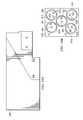
- FIG. 1is a diagrammatic representation of one embodiment of a pumping system
- FIG. 2is a diagrammatic representation of a multiple stage pump (“multi-stage pump”) according to one embodiment of the present invention
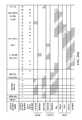
- FIG. 3is a diagrammatic representation of valve and motor timings for one embodiment of the present invention.
- FIGS. 4A , 4 B, 5 A, 5 C, and 5 Dare diagrammatic representations of various embodiments of a multi-stage pump
- FIG. 5Bis a diagrammatic representation of one embodiment of a dispense block
- FIG. 6is a diagrammatic representation of one embodiment of a partial assembly of a multi-stage pump
- FIG. 7is a diagrammatic representation of another embodiment of a partial assembly of a multi-stage pump.
- FIG. 8Ais a diagrammatic representation of one embodiment of a portion of a multi-stage pump
- FIG. 8Bis diagrammatic representation of a section of the embodiment of multi-stage pump of FIG. 8A including the dispense chamber;
- FIG. 8Cis a diagrammatic representation of a section of the embodiment of multi-stage pump of FIG. 8B ;
- FIG. 9is a diagrammatic representation illustrating the construction of one or more valves using an embodiment of a valve plate and dispense block
- FIG. 10Ais a diagrammatic representation of a side view of a dispense block and FIG. 10B is a diagrammatic representation of an end surface of the dispense block;
- FIG. 11is a diagrammatic representation of one embodiment of a valve plate
- FIG. 12is a diagrammatic representation of another view of an embodiment of a valve plate
- FIG. 13is a diagrammatic representation of a view of an embodiment of a valve plate showing passages defined in the valve plate;
- FIG. 14Ais a diagrammatic representation of a valve plate having a flat valve chamber
- FIG. 14Bis a diagrammatic representation of a valve plate having a hemispherical valve chamber
- FIG. 15is a graph illustrating how a hemispherically shaped valve chamber reduces displacement volume fluctuations due to vacuum
- FIG. 16Ais a diagrammatic representation of one embodiment of a portion of a valve plate
- FIG. 16Bis a diagrammatic representation of another embodiment of a portion of a valve plate
- FIG. 17is a diagrammatic representation of a motor assembly with a brushless DC motor, according to one embodiment of the invention.
- FIG. 18is a plot diagram comparing average torque output and speed range of a brushless DC motor and a stepper motor, according to one embodiment of the invention.
- FIG. 19is a plot diagram comparing average motor current and load between a brushless DC motor and a stepper motor, according to one embodiment of the invention.
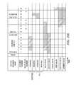
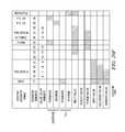
- FIGS. 20A , 20 C, 20 D, 20 E and 20 Fare chart diagrams illustrating cycle timing of a stepper motor and a BLDCM in various stages, according to one embodiment of the invention and FIG. 20B is chart diagram illustrating one embodiment of configuring a stepper motor and BLDCM;
- FIGS. 21A-21Care diagrammatic representations of a rolling diaphragm and a dispense chamber
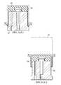
- FIG. 22provides dimensions for an example embodiment of a multi-stage pump
- FIG. 23is a diagrammatic representation of a single stage pump.
- FIGURESPreferred embodiments of the present invention are illustrated in the FIGURES, like numerals being used to refer to like and corresponding parts of the various drawings. To the extent dimensions are provided, they are provided by way of example for particular implementations and are not provided by way of limitation. Embodiments can be implemented in a variety of configurations.
- Embodiments of the present inventionare related to a pumping system that accurately dispenses fluid using a multiple stage (“multi-stage”) pump with reduced form factor.
- Embodiments of the present inventioncan be utilized for the dispense of photo-resist and other photosensitive chemicals in semiconductor manufacturing.
- FIG. 1is a diagrammatic representation of a pumping system 10 .
- the pumping system 10can include a fluid source 15 , a pump controller 20 and a multi-stage pump 100 , which work together to dispense fluid onto a wafer 25 .
- the operation of multi-stage pump 100can be controlled by pump controller 20 , which can be onboard multi-stage pump 100 or connected to multi-stage pump 100 via a one or more communications links for communicating control signals, data or other information. Additionally, the functionality of pump controller 20 can be distributed between an onboard controller and another controller.
- Pump controller 20can include a computer readable medium 27 (e.g., RAM, ROM, Flash memory, optical disk, magnetic drive or other computer readable medium) containing a set of control instructions 30 for controlling the operation of multi-stage pump 100 .
- a processor 35e.g., CPU, ASIC, RISC, DSP or other processor
- processorscan execute the instructions.
- One example of a processoris the Texas Instruments TMS320F2812PGFA 16-bit DSP (Texas Instruments is Dallas, Tex. based company).
- controller 20communicates with multi-stage pump 100 via communications links 40 and 45 .
- Communications links 40 and 45can be networks (e.g., Ethernet, wireless network, global area network, DeviceNet network or other network known or developed in the art), a bus (e.g., SCSI bus) or other communications link.
- Controller 20can be implemented as an onboard PCB board, remote controller or in other suitable manner.
- Pump controller 20can include appropriate interfaces (e.g., network interfaces, I/O interfaces, analog to digital converters and other components) to controller to communicate with multi-stage pump 100 .
- pump controller 20can include a variety of computer components known in the art including processors, memories, interfaces, display devices, peripherals or other computer components not shown for the sake of simplicity.
- Pump controller 20can control various valves and motors in multi-stage pump to cause multi-stage pump to accurately dispense fluids, including low viscosity fluids (i.e., less than 100 centipoise) or other fluids.
- An I/O interface connectoras described in U.S. Provisional Patent Application No. 60/741,657, entitled “I/O INTERFACE SYSTEM AND METHOD FOR A PUMP,” by Cedrone et al., filed Dec. 2, 2005, which is hereby fully incorporated by reference herein, can be used to connected pump controller 20 to a variety of interfaces and manufacturing tools.
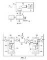
- FIG. 2is a diagrammatic representation of a multi-stage pump 100 .
- Multi-stage pump 100includes a feed stage portion 105 and a separate dispense stage portion 110 .
- filter 120Located between feed stage portion 105 and dispense stage portion 110 , from a fluid flow perspective, is filter 120 to filter impurities from the process fluid.
- a number of valvescan control fluid flow through multi-stage pump 100 including, for example, inlet valve 125 , isolation valve 130 , barrier valve 135 , purge valve 140 , vent valve 145 and outlet valve 147 .
- Dispense stage portion 110can further include a pressure sensor 112 that determines the pressure of fluid at dispense stage 110 . The pressure determined by pressure sensor 112 can be used to control the speed of the various pumps as described below.
- Example pressure sensorsinclude ceramic and polymer pesioresistive and capacitive pressure sensors, including those manufactured by Metallux AG, of Korb, Germany. According to one embodiment, the face of pressure sensor 112 that contacts the process fluid is a periluoropolymer. Pump 100 can include additional pressure sensors, such as a pressure sensor to read pressure in feed chamber 155 .
- Feed stage 105 and dispense stage 110can include rolling diaphragm pumps to pump fluid in multi-stage pump 100 .
- Feed-stage pump 150(“feed pump 150 ”), for example, includes a feed chamber 155 to collect fluid, a feed stage diaphragm 160 to move within feed chamber 155 and displace fluid, a piston 165 to move feed stage diaphragm 160 , a lead screw 170 and a stepper motor 175 .
- Lead screw 170couples to stepper motor 175 through a nut, gear or other mechanism for imparting energy from the motor to lead screw 170 .
- feed motor 175rotates a nut that, in turn, rotates lead screw 170 , causing piston 165 to actuate.
- Dispense-stage pump 180(“dispense pump 180 ”) can similarly include a dispense chamber 185 , a dispense stage diaphragm 190 , a piston 192 , a lead screw 195 , and a dispense motor 200 .
- Dispense motor 200can drive lead screw 195 through a threaded nut (e.g., a Torlon or other material nut).
- feed stage 105 and dispense stage 110can be a variety of other pumps including pneumatically or hydraulically actuated pumps, hydraulic pumps or other pumps.
- feed stage 105 and dispense stage 110can be a variety of other pumps including pneumatically or hydraulically actuated pumps, hydraulic pumps or other pumps.
- pneumatically actuated pumpfor the feed stage and a stepper motor driven hydraulic pump.
- the use of motors at both stagesprovides an advantage in that the hydraulic piping, control systems and fluids are eliminated, thereby reducing space and potential leaks.
- Feed motor 175 and dispense motor 200can be any suitable motor.
- dispense motor 200is a Permanent-Magnet Synchronous Motor (“PMSM”).
- the PMSMcan be controlled by a digital signal processor (“DSP”) utilizing Field-Oriented Control (“FOC”) or other type of position/speed control known in the art at motor 200 , a controller onboard multi-stage pump 100 or a separate pump controller (e.g. as shown in FIG. 1 ).
- PMSM 200can further include an encoder (e.g., a fine line rotary position encoder) for real time feedback of dispense motor 200 's position.
- FIGS. 17-19describe one embodiment of a PMSM motor.
- a position sensorgives accurate and repeatable control of the position of piston 192 , which leads to accurate and repeatable control over fluid movements in dispense chamber 185 .
- a PMSMcan run at low velocities with little or no vibration.
- Feed motor 175can also be a PMSM or a stepper motor. It should also be noted that the feed pump can include a home sensor to indicate when the feed pump is in its home position.
- valves of multi-stage pump 100are opened or closed to allow or restrict fluid flow to various portions of multi-stage pump 100 .
- these valvescan be pneumatically actuated (i.e., gas driven) diaphragm valves that open or close depending on whether pressure or a vacuum is asserted.
- any suitable valvecan be used.
- One embodiment of a valve plate and corresponding valve componentsis described below in conjunction with FIGS. 9-16 .
- multi-stage pump 100can be controlled according to a variety of control schemes including, but not limited to those described in U.S. Provisional Patent Application No. 60/741,682 entitled “SYSTEM AND METHOD FOR PRESSURE COMPENSATION IN A PUMP” by Inventors Cedrone et al., filed Dec. 2, 2005; U.S. patent application Ser. No. 11/502,729 entitled “SYSTEMS AND METHODS FOR FLUID FLOW CONTROL IN AN IMMERSION LITHOGRAPHY SYSTEM” by Inventors Clarke et al., filed Aug. 11, 2006; U.S. patent application Ser. No.
- multi-stage pump 100can include a ready segment, dispense segment, fill segment, pre-filtration segment, filtration segment, vent segment, purge segment and static purge segment.
- inlet valve 125is opened and feed stage pump 150 moves (e.g., pulls) feed stage diaphragm 160 to draw fluid into feed chamber 155 . Once a sufficient amount of fluid has filled feed chamber 155 , inlet valve 125 is closed. During the filtration segment, feed-stage pump 150 moves feed stage diaphragm 160 to displace fluid from feed chamber 155 . Isolation valve 130 and barrier valve 135 are opened to allow fluid to flow through filter 120 to dispense chamber 185 . Isolation valve 130 , according to one embodiment, can be opened first (e.g., in the “pre-filtration segment”) to allow pressure to build in filter 120 and then barrier valve 135 opened to allow fluid flow into dispense chamber 185 .
- both isolation valve 130 and barrier valve 135can be opened and the feed pump moved to build pressure on the dispense side of the filter.
- dispense pump 180can be brought to its home position.
- U.S. Provisional Patent Application No. 60/630,384entitled “SYSTEM AND METHOD FOR A VARIABLE HOME POSITION DISPENSE SYSTEM” by Laverdiere, et al. filed Nov. 23, 2004 and PCT Application No. PCT/US2005/042127, entitled “SYSTEM AND METHOD FOR VARIABLE HOME POSITION DISPENSE SYSTEM”, by Applicant Entegris, Inc. and Inventors Laverdiere et al., filed Nov.
- the home position of the dispense pumpcan be a position that gives the greatest available volume at the dispense pump for the dispense cycle, but is less than the maximum available volume that the dispense pump could provide.
- the home positionis selected based on various parameters for the dispense cycle to reduce unused hold up volume of multi-stage pump 100 .
- Feed pump 150can similarly be brought to a home position that provides a volume that is less than its maximum available volume.
- isolation valve 130is opened, barrier valve 135 closed and vent valve 145 opened.
- barrier valve 135can remain open during the vent segment and close at the end of the vent segment.
- the pressurecan be understood by the controller because the pressure in the dispense chamber, which can be measured by pressure sensor 112 , will be affected by the pressure in filter 120 .
- Feed-stage pump 150applies pressure to the fluid to remove air bubbles from filter 120 through open vent valve 145 .
- Feed-stage pump 150can be controlled to cause venting to occur at a predefined rate, allowing for longer vent times and lower vent rates, thereby allowing for accurate control of the amount of vent waste.
- feed pumpis a pneumatic style pump
- a fluid flow restrictioncan be placed in the vent fluid path, and the pneumatic pressure applied to feed pump can be increased or decreased in order to maintain a “venting” set point pressure, giving some control of an otherwise un-controlled method.
- isolation valve 130is closed, barrier valve 135 , if it is open in the vent segment, is closed, vent valve 145 closed, and purge valve 140 opened and inlet valve 125 opened.
- Dispense pump 180applies pressure to the fluid in dispense chamber 185 to vent air bubbles through purge valve 140 .
- purge valve 140remains open to continue to vent air. Any excess fluid removed during the purge or static purge segments can be routed out of multi-stage pump 100 (e.g., returned to the fluid source or discarded) or recycled to feed-stage pump 150 .
- inlet valve 125 , isolation valve 130 and barrier valve 135can be opened and purge valve 140 closed so that feed-stage pump 150 can reach ambient pressure of the source (e.g., the source bottle). According to other embodiments, all the valves can be closed at the ready segment.
- outlet valve 147opens and dispense pump 180 applies pressure to the fluid in dispense chamber 185 . Because outlet valve 147 may react to controls more slowly than dispense pump 180 , outlet valve 147 can be opened first and some predetermined period of time later dispense motor 200 started. This prevents dispense pump 180 from pushing fluid through a partially opened outlet valve 147 . Moreover, this prevents fluid moving up the dispense nozzle caused by the valve opening, followed by forward fluid motion caused by motor action. In other embodiments, outlet valve 147 can be opened and dispense begun by dispense pump 180 simultaneously.
- An additional suckback segmentcan be performed in which excess fluid in the dispense nozzle is removed.
- outlet valve 147can close and a secondary motor or vacuum can be used to suck excess fluid out of the outlet nozzle.
- outlet valve 147can remain open and dispense motor 200 can be reversed to such fluid back into the dispense chamber.
- the suckback segmenthelps prevent dripping of excess fluid onto the wafer.
- FIG. 3this figure provides a diagrammatic representation of valve and dispense motor timings for various segments of the operation of multi-stage pump 100 of FIG. 2 .
- Other sequencesare shown in FIGS. 20 A and 20 C-F. While several valves are shown as closing simultaneously during segment changes, the closing of valves can be timed slightly apart (e.g., 100 milliseconds) to reduce pressure spikes. For example, between the vent and purge segment, isolation valve 130 can be closed shortly before vent valve 145 . It should be noted, however, other valve timings can be utilized in various embodiments of the present invention.
- the fill/dispense stagescan be performed at the same time, in which case both the inlet and outlet valves can be open in the dispense/fill segment.
- specific segmentsdo not have to be repeated for each cycle.
- the purge and static purge segmentsmay not be performed every cycle.
- the vent segmentmay not be performed every cycle.
- valvescan cause pressure spikes in the fluid within multi-stage pump 100 . Because outlet valve 147 is closed during the static purge segment, closing of purge valve 140 at the end of the static purge segment, for example, can cause a pressure increase in dispense chamber 185 . This can occur because each valve may displace a small volume of fluid when it closes. More particularly, in many cases before a fluid is dispensed from chamber 185 a purge cycle and/or a static purge cycle is used to purge air from dispense chamber 185 in order to prevent sputtering or other perturbations in the dispense of the fluid from multi-stage pump 100 .
- purge valve 140closes in order to seal dispense chamber 185 in preparation for the start of the dispense.
- purge valve 140forces a volume of extra fluid (approximately equal to the hold-up volume of purge valve 140 ) into dispense chamber 185 , which, in turn, causes an increase in pressure of the fluid in dispense chamber 185 above the baseline pressure intended for the dispense of the fluid.
- This excess pressure(above the baseline) may cause problems with a subsequent dispense of fluid.
- Embodiments of the present inventionaccount for the pressure increase due to various valve closings within the system to achieve a desirable starting pressure for the beginning of the dispense segment, account for differing head pressures and other differences in equipment from system to system by allowing almost any baseline pressure to be achieved in dispense chamber 185 before a dispense.
- dispense motor 200may be reversed to back out piston 192 a predetermined distance to compensate for any pressure increase caused by the closure of barrier valve 135 , purge valve 140 and/or any other sources which may cause a pressure increase in dispense chamber 185 .
- embodiments of the present inventionprovide a multi-stage pump with gentle fluid handling characteristics. By compensating for pressure fluctuations in a dispense chamber before a dispense segment, potentially damaging pressure spikes can be avoided or mitigated. Embodiments of the present invention can also employ other pump control mechanisms and valve timings to help reduce deleterious effects of pressure on a process fluid.
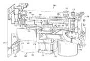
- FIG. 4Ais a diagrammatic representation of one embodiment of a pump assembly for multi-stage pump 100 .
- Multi-stage pump 100can include a dispense block 205 that defines various fluid flow paths through multi-stage pump 100 and at least partially defines feed chamber 155 and dispense chamber 185 .
- Dispense pump block 205can be a unitary block of PTFE, modified PTFE or other material. Because these materials do not react with or are minimally reactive with many process fluids, the use of these materials allows flow passages and pump chambers to be machined directly into dispense block 205 with a minimum of additional hardware. Dispense block 205 consequently reduces the need for piping by providing an integrated fluid manifold.
- Dispense block 205can include various external inlets and outlets including, for example, inlet 210 through which the fluid is received, vent outlet 215 for venting fluid during the vent segment, and dispense outlet 220 through which fluid is dispensed during the dispense segment.
- Dispense block 205in the example of FIG. 4A , does not include an external purge outlet as purged fluid is routed back to the feed chamber (as shown in FIG. 5A and FIG. 5B ). In other embodiments of the present invention, however, fluid can be purged externally.
- Dispense block 205routes fluid to the feed pump, dispense pump and filter 120 .
- a pump cover 225can protect feed motor 175 and dispense motor 200 from damage, while piston housing 227 can provide protection for piston 165 and piston 192 and, according to one embodiment of the present invention, be formed of polyethylene or other polymer.
- Valve plate 230provides a valve housing for a system of valves (e.g., inlet valve 125 , isolation valve 130 , barrier valve 135 , purge valve 140 and vent valve 145 of FIG. 2 ) that can be configured to direct fluid flow to various components of multi-stage pump 100 .
- each of inlet valve 125 , isolation valve 130 , barrier valve 135 , purge valve 140 and vent valve 145is at least partially integrated into valve plate 230 and is a diaphragm valve that is either opened or closed depending on whether pressure or vacuum is applied to the corresponding diaphragm.
- some of the valvesmay be external to dispense block 205 or arranged in additional valve plates.
- a sheet of PTFEis sandwiched between valve plate 230 and dispense block 205 to form the diaphragms of the various valves.
- Valve plate 230includes a valve control inlet for each valve to apply pressure or vacuum to the corresponding diaphragm.
- inlet 235corresponds to barrier valve 135 , inlet 240 to purge valve 140 , inlet 245 to isolation valve 130 , inlet 250 to vent valve 145 , and inlet 255 to inlet valve 125 (outlet valve 147 is external in this case).
- outlet valve 147is external in this case.
- valve control gas and vacuumare provided to valve plate 230 via valve control supply lines 260 , which run from a valve control manifold (in an area beneath top cover 263 or housing cover 225 ), through dispense block 205 to valve plate 230 .
- Valve control gas supply inlet 265provides a pressurized gas to the valve control manifold and vacuum inlet 270 provides vacuum (or low pressure) to the valve control manifold.
- the valve control manifoldacts as a three way valve to route pressurized gas or vacuum to the appropriate inlets of valve plate 230 via supply lines 260 to actuate the corresponding valve(s).
- a valve platecan be used that reduces the hold-up volume of the valve, eliminates volume variations due to vacuum fluctuations, reduces vacuum requirements and reduces stress on the valve diaphragm.
- FIG. 4Bis a diagrammatic representation of another embodiment of multistage pump 100 . Many of the features shown in FIG. 4B are similar to those described in conjunction with FIG. 4A above. However, the embodiment of FIG. 4B includes several features to prevent fluid drips from entering the area of multi-stage pump 100 housing electronics. Fluid drips can occur, for example, when an operator connects or disconnects a tube from inlet 210 , outlet 220 or vent 215 .
- the “drip-proof” featuresare designed to prevent drips of potentially harmful chemicals from entering the pump, particularly the electronics chamber and do not necessarily require that the pump be “water-proof” (e.g., submersible in fluid without leakage). According to other embodiments, the pump can be fully sealed.
- dispense block 205can include a vertically protruding flange or lip 272 protruding outward from the edge of dispense block 205 that meets top cover 263 .
- the top of top cover 263is flush with the top surface of lip 272 . This causes drips near the top interface of dispense block 205 and top cover 263 to tend to run onto dispense block 205 , rather than through the interface.
- top cover 263is flush with the base of lip 272 or otherwise inwardly offset from the outer surface of lip 272 .
- top cover 263 and lip 272This causes drips to tend to flow down the corner created by top cover 263 and lip 272 , rather than between top cover 263 and dispense block 205 . Additionally, a rubber seal is placed between the top edge of top cover 263 and back plate 271 to prevent drips from leaking between top cover 263 and back plate 271 .
- Dispense block 205can also include sloped feature 273 that includes a sloped surface defined in dispense block 205 that slopes down and away from the area of pump 100 housing electronics. Consequently, drips near the top of dispense block 205 are lead away from the electronics. Additionally, pump cover 225 can also be offset slightly inwards from the outer side edges of dispense block 205 so that drips down the side of pump 100 will tend to flow past the interface of pump cover 225 and other portions of pump 100 .
- multi-stage pump 100can include seals, sloped features and other features to prevent drips from entering portions of multi-stage pump 100 housing electronics.
- back plate 271can include features to further “drip-proof” multi-stage pump 100 .
- FIG. 5Ais a diagrammatic representation of one embodiment of multi-stage pump 100 with dispense block 205 made transparent to show the fluid flow passages defined there through.
- Dispense block 205defines various chambers and fluid flow passages for multi-stage pump 100 .
- feed chamber 155 and dispense chamber 185can be machined directly into dispense block 205 .
- various flow passagescan be machined into dispense block 205 .
- Fluid flow passage 275(shown in FIG. 5C ) runs from inlet 210 to the inlet valve.
- Fluid flow passage 280runs from the inlet valve to feed chamber 155 , to complete the pump inlet path from inlet 210 to feed pump 150 .
- Inlet valve 125 in valve housing 230regulates flow between inlet 210 and feed pump 150 .
- Flow passage 285routes fluid from feed pump 150 to isolation valve 130 in valve plate 230 .
- the output of isolation valve 130is routed to filter 120 by another flow passage (not shown). These flow paths act as a feed stage outlet flow path to filter 120 .
- the output of vent valve 145is routed to vent outlet 215 to complete a vent flow path while the output of barrier valve 135 is routed to dispense pump 180 via flow passage 290 .
- the flow passage from filter 120 to barrier valve 135 and flow passage 290act as feed stage inlet flow path.
- Dispense pumpduring the dispense segment, can output fluid to outlet 220 via flow passage 295 (e.g., a pump outlet flow path) or, in the purge segment, to the purge valve through flow passage 300 .
- fluidcan be returned to feed pump 150 through flow passage 305 .
- flow passage 300 and flow passage 305act as a purge flow path to return fluid to feed chamber 155 .
- dispense block 205can act as the piping for the process fluid between various components of multi-stage pump 100 , obviating or reducing the need for additional tubing. In other cases, tubing can be inserted into dispense block 205 to define the fluid flow passages.
- FIG. 5Bprovides a diagrammatic representation of dispense block 205 made transparent to show several of the flow passages therein, according to one embodiment.
- FIG. 5Aalso shows multi-stage pump 100 with pump cover 225 and top cover 263 removed to show feed pump 150 , including feed stage motor 175 , dispense pump 180 , including dispense motor 200 , and valve control manifold 302 .
- portions of feed pump 150 , dispense pump 180 and valve plate 230can be coupled to dispense block 205 using bars (e.g., metal bars) inserted into corresponding cavities in dispense block 205 .
- Each barcan include on or more threaded holes to receive a screw.
- dispense motor 200 and piston housing 227can be mounted to dispense block 205 via one or more screws (e.g., screw 312 and screw 314 ) that run through screw holes in dispense block 205 to thread into corresponding holes in bar 316 .
- screwse.g., screw 312 and screw 314
- this mechanism for coupling components to dispense block 205is provided by way of example and any suitable attachment mechanism can be used.
- Back plate 271can include inwardly extending tabs (e.g., bracket 274 ) to which top cover 263 and pump cover 225 mount. Because top cover 263 and pump cover 225 overlap bracket 274 (e.g., at the bottom and back edges of top cover 263 and the top and back edges pump cover 225 ) drips are prevented from flowing into the electronics area between any space between the bottom edge of top cover 263 and the top edge of pump cover 225 or at the back edges of top cover 263 and pump cover 225 .
- bracket 274e.g., at the bottom and back edges of top cover 263 and the top and back edges pump cover 225
- Manifold 302can include a set of solenoid valves to selectively direct pressure/vacuum to valve plate 230 . When a particular solenoid is on thereby directing vacuum or pressure to a valve, depending on implementation, the solenoid will generate heat.
- manifold 302is mounted below a PCB board (which is mounted to back plate 271 and better shown in FIG. 5C ) away from dispense block 205 and particularly dispense chamber 185 .
- Manifold 302can be mounted to a bracket that is, in turn, mounted to back plate 271 or can be coupled otherwise to back plate 271 .
- Back plate 271can be made of stainless steel machined aluminum or other material that can dissipate heat from manifold 302 and the PCB. Put another way, back plate 271 can act as a heat dissipating bracket for manifold 302 and the PCB. Pump 100 can be further mounted to a surface or other structure to which heat can be conducted by back plate 271 . Thus, back plate 271 and the structure to which it is attached act as a heat sink for manifold 302 and the electronics of pump 100 .
- FIG. 5Cis a diagrammatic representation of multi-stage pump 100 showing supply lines 260 for providing pressure or vacuum to valve plate 230 .
- the valves in valve plate 230can be configured to allow fluid to flow to various components of multi-stage pump 100 . Actuation of the valves is controlled by the valve control manifold 302 that directs either pressure or vacuum to each supply line 260 .
- Each supply line 260can include a fitting (an example fitting is indicated at 318 ) with a small orifice. This orifice may be of a smaller diameter than the diameter of the corresponding supply line 260 to which fitting 318 is attached. In one embodiment, the orifice may be approximately 0.010 inches in diameter.
- the orifice of fitting 318may serve to place a restriction in supply line 260 .
- the orifice in each supply line 260helps mitigate the effects of sharp pressure differences between the application of pressure and vacuum to the supply line and thus may smooth transitions between the application of pressure and vacuum to the valve.
- the orificehelps reduce the impact of pressure changes on the diaphragm of the downstream valve. This allows the valve to open and close more smoothly and more slowly which may lead to smoother pressure transitions within the system which may be caused by the opening and closing of the valve and may in fact increase the longevity of the valve itself.
- FIG. 5Calso illustrates PCB 397 .
- Manifold 302can receive signals from PCB board 397 to cause solenoids to open/close to direct vacuum/pressure to the various supply lines 260 to control the valves of multi-stage pump 100 .
- manifold 302can be located at the distal end of PCB 397 from dispense block 205 to reduce the effects of heat on the fluid in dispense block 205 .
- components that generate heatcan be placed on the side of PCB away from dispense block 205 , again reducing the effects of heat.
- FIG. 5Dis a diagrammatic representation of an embodiment of pump 100 in which manifold 302 is mounted directly to dispense block 205 .
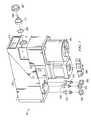
- FIG. 6is a diagrammatic representation illustrating the partial assembly of one embodiment of multi-stage pump 100 .
- valve plate 230is already coupled to dispense block 205 , as described above.
- diaphragm 160 with lead screw 170can be inserted into the feed chamber 155
- diaphragm 190 with lead screw 195can be inserted into dispense chamber 185 .
- Piston housing 227is placed over the feed and dispense chambers with the lead screws running there through.
- a single shaped blockacts as a piston housing for the dispense stage piston and feed stage piston, however each stage can have separate housing components.
- Dispense motor 200couples to lead screw 195 and can impart linear motion to lead screw 195 through a rotating female-threaded nut.
- feed motor 175is coupled to lead screw 170 and can also impart linear motion to lead screw 170 through a rotating female-threaded nut.
- a spacer 319can be used to offset dispense motor 200 from piston housing 227 .
- Screws in the embodiment shownattach feed motor 175 and dispense motor 200 to multi-stage pump 100 using bars with threaded holes inserted into dispense block 205 , as described in conjunction with FIG. 5 .
- screw 315can be threaded into threaded holes in bar 320 and screw 325 can be threaded into threaded holes in bar 330 to attach feed motor 175 .
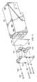
- FIG. 7is a diagrammatic representation further illustrating a partial assembly of one embodiment of multi-stage pump 100 .
- FIG. 7illustrates adding filter fittings 335 , 340 and 345 to dispense block 205 .
- Nuts 350 , 355 , 360can be used to hold filter fittings 335 , 340 , 345 .
- Each filter fittingleads to one of the flow passage to feed chamber, the vent outlet or dispense chamber (all via valve plate 230 ).
- Pressure sensor 112can be inserted into dispense block 205 , with the pressure sensing face exposed to dispense chamber 185 .
- An o-ring 365seals the interface of pressure sensor 112 with dispense chamber 185 .
- Pressure sensor 112is held securely in place by nut 367 .
- valve control linesrun from the outlet of the valve manifold (e.g., valve manifold 302 ) into dispense block 205 at opening 375 and out the top of dispense block 205 to valve plate 230 (as shown in FIG. 4 ).
- the pressure sensorcan be located to read pressure in the feed chamber or multiple pressure sensors can be used to determine the pressure in the feed chamber, the dispense chamber or elsewhere in the pump.
- FIG. 7also illustrates several interfaces for communications with a pump controller (e.g., pump controller 20 of FIG. 1 ).
- Pressure sensor 112communicates pressure readings to controller 20 via one or more wires (represented at 380 ).
- Dispense motor 200includes a motor control interface 385 to receive signals from pump controller 20 to cause dispense motor 200 to move. Additionally, dispense motor 200 can communicate information to pump controller 20 including position information (e.g., from a position line encoder).
- feed motor 175can include a communications interface 390 to receive control signals from and communicate information to pump controller 20 .
- FIG. 8Aillustrates a side view of a portion of multi-stage pump 100 including dispense block 205 , valve plate 230 , piston housing 227 , lead screw 170 and lead screw 195 .
- FIG. 8Billustrates a section view of FIG. 8A showing dispense block 205 , dispense chamber 185 , piston housing 227 , lead screw 195 , piston 192 and dispense diaphragm 190 .
- dispense chamber 185can be at least partially defined by dispense block 205 .
- piston 192can move up (relative to the alignment shown in FIG.
- FIG. 8Billustrates a portion of FIG. 8B .
- dispense diaphragm 190includes a tong 395 that fits into a grove 400 in dispense block 205 .
- the edge of dispense diaphragm 190in this embodiment, is thus sealed between piston housing 227 and dispense block 205 .
- dispense pump and/or feed pump 150can be a rolling diaphragm pump.
- multi-stage pump 100 described in conjunction with FIGS. 1-8Cis provided by way of example, but not limitation, and embodiments of the present invention can be implemented for other multi-stage pump configurations.
- FIG. 9illustrates one embodiment of various components used in forming input valve 125 , isolation valve 130 , barrier valve 135 , purge valve 140 and vent valve 145 according to one embodiment of the present invention.
- Outlet valve 147is external to the pump in this embodiment.
- dispense block 205has an end surface 1000 upon which diaphragm 1002 is placed.
- O-rings 1004are aligned with corresponding rings on end surface 1000 and press diaphragm 1002 partially into the rings in dispense block 205 .
- Valve plate 230also includes corresponding rings in which O-rings 1004 are at least partially seated.
- Valve plate 230is connected to dispense block 205 using washers and screws (shown at 1006 and 1008 ).
- the body of each valvecan be formed of multiple pieces such as the dispense block (or other part of the pump body) and a valve plate.
- a sheet of elastomeric material, illustrated as diaphragm 1002is sandwiched between valve plate 230 and dispense block 205 to form the diaphragms of the various valves.
- Diaphragm 1002can be a single diaphragm used for each of input valve 125 , isolation valve 130 , barrier valve 135 , purge valve 140 and vent valve 145 .
- Diaphragm 1002can be PTFE, modified PTFE, a composite material of different layer types or other suitable material that is non-reactive with the process fluid. According to one embodiment, diaphragm 1002 can be approximately 0.013 inches thick. It should be noted that in other embodiments, separate diaphragms can be used for each valve and other types of diaphragms can be used.
- FIG. 10Aillustrates one embodiment of a side view of dispense block 205 having end surface 1000 .
- FIG. 10Billustrates one embodiment of end surface 1000 of dispense block 205 .
- end surface 1000includes an annular ring into which an O-Ring partially pushes a portion of the diaphragm.
- ring 1010corresponds to input valve 125
- ring 1012corresponds to isolation valve 130
- ring 1014corresponds to barrier valve 135
- ring 1016corresponds to purge valve 130
- ring 1018corresponds to vent valve 145 .
- FIG. 10Balso illustrates the input/output flow passages for each valve.
- Flow passage 1020leads from the inlet 210 (shown in FIG.
- inlet valve 125 and flow passage 280leads from inlet valve 125 to the feed chamber; for isolation valve 130 , flow passage 305 leads from the feed chamber to isolation valve 130 and flow passage 1022 leads from isolation valve 130 to the filter; for barrier valve 135 , flow passage 1024 leads from the filter to barrier valve 135 and flow passage 290 leads from barrier valve 135 to the dispense chamber; for purge valve 140 , flow passage 300 leads from the dispense chamber and flow passage 305 leads to the feed chamber; and for vent valve 145 , flow passage 1026 leads from the filter and flow passage 1027 leads out of the pump (e.g., out vent 215 , shown in FIG. 4 ).
- FIG. 11is a diagrammatic representation of one embodiment of the outer side of valve plate 230 .
- valve plate 230includes various holes (e.g., represented at 1028 ) through which screws can be inserted to attached valve plate 230 to dispense block 205 .
- the valve control inlets for each valveto apply pressure or vacuum to the corresponding diaphragm.
- inlet 235corresponds to barrier valve 135
- inlet 245 to isolation valve 130inlet 250 to vent valve 145
- inlet 255to inlet valve 125 .
- FIG. 12is a diagrammatic representation of valve plate 230 showing the inner surface of valve plate 230 (i.e., the surface that faces dispense block 205 ).
- valve plate 230For each of inlet valve 125 , isolation valve 130 , barrier valve 135 , purge valve 140 and vent valve 145 , valve plate 230 at least partially defines a valve chamber into which a diaphragm (e.g., diaphragm 1002 ) is displaced when the valve opens.
- chamber 1025corresponds to inlet valve 125 , chamber 1030 to isolation valve 130 , chamber 1035 to barrier valve 135 , chamber 1040 to purge valve 140 and chamber 1045 to vent valve 145 .
- Each valve chamberpreferably has an arced valve seat from the edge of the valve chamber to the center of the valve chamber towards which the diaphragm displaces.
- the edge of the valve chamberis circular (as shown in FIG. 12 ) and radius of the arced surface is constant, the valve chamber will have a semi-hemispherical shape.
- a flow passageis defined for each valve for the application of a valve control gas/vacuum or other pressure to cause the diaphragm to be displaced between an open position and closed position for a valve.
- flow passage 1050runs from an input on valve control plate 230 to the corresponding opening in the arced surface of purge valve chamber 1040 .
- diaphragm 1002can be displaced into chamber 1040 , thereby causing purge valve 140 to open.
- An annular ring around each valve chamberprovides for sealing with O-rings 1004 .
- annular ring 1055is used to partially contain an o-ring to seal purge valve 140 .
- FIG. 13is a diagrammatic representation of valve plate 230 made transparent to show the flow passages, including flow passage 1050 , for the application of pressure or vacuum to each valve.
- FIG. 14Ais a diagrammatic representation of a valve plate design in which the displacement volume of the valve varies with the amount of pressure applied to diaphragm 1002 .
- Shown in FIG. 14Ais an embodiment of a purge valve.
- a valve plate 1060is connected to dispense block 205 .
- Diaphragm 1002is sandwiched between valve plate 1060 and dispense block 205 .
- Valve plate 1060forms a valve chamber 1062 into which diaphragm 1002 is displaced when vacuum is applied through flow passage 1065 .
- An annular ring 1070 surrounding valve chamberseats o-ring 1004 .
- o-ring 1004presses diaphragm 1002 into annular ring 1016 , which further seals the purge valve.
- valve chamber 1062has chamfered sides to a substantially flat surface (indicated at 1067 ) towards which diaphragm 1002 displaces.
- diaphragm 1002displaces towards surface 1067 in a generally semi-hemispherical shape. This means that there will be some dead space (i.e., unused space) between diaphragm 1002 and valve plate 1060 . This unused space is indicated at area 1070 .
- the amount of pull applied through flow passage 1065increases (i.e., by increasing the vacuum), there is less unused space, however diaphragm 1002 does not completely bottom out. Consequently, depending on the pressure used to displace diaphragm 1002 , the displacement volume of diaphragm 1002 changes (e.g., the amount of volume in the bowl of the diaphragm, generally indicated at 1072 , changes).
- diaphragm 1002moves to seal the inlet and outlet (in this case flow passage 295 from the dispense chamber and flow passage 305 to the feed chamber).
- the volume of fluid in area 1072will therefore be moved out of purge valve 140 . This will cause a pressure spike in the dispense chamber (or other enclosed space to which the fluid is moved).
- the amount of fluid displaced by the valvewill depend on how much volume was held up in the valve. Because this volume varies with the amount of pressure applied, different pumps of the same design, but operating using different vacuum pressures, will show different pressure spikes in the dispense chamber or other enclosed space.
- diaphragm 1002is plastic, the displacement of diaphragm 1002 for a given vacuum pressure will vary depending on temperature. Consequently, the volume of unused area 1070 will change depending on temperature. Because the displacement volume of the valve of FIG. 14A varies based on the vacuum applied and temperature, it is difficult to accurately compensate for the volume displaced by the pump opening and closing.
- FIG. 14Bis a diagrammatic representation of one embodiment of a purge valve using a valve plate design according to one embodiment of the present invention. Shown in FIG. 14B is an embodiment of purge valve 140 .
- valve plate 230is connected to dispense block 205 .
- Diaphragm 1002is sandwiched between valve plate 230 and dispense block 205 .
- Valve plate 230forms a valve chamber 1040 into which diaphragm 1002 can be displaced based on the application of vacuum (or low pressure) through flow passage 1050 .
- valve plate 230When valve plate 230 is attached to dispense block 205 , o-ring 1004 presses diaphragm 1002 into annular ring 1016 , further sealing purge valve 140 . This creates a seal and fixes diaphragm 1002 .
- dispense block 205can be PTFE or modified PTFE, diaphragm 1002 PFTE or modified PTFE and valve plate 230 machined aluminum. Other suitable materials can be used.
- valve chamber 1040 into which diaphragm 1002 displacesis semi-hemispherical.
- diaphragm 1002displaces towards the hemispherical surface in a semi-hemispherical shape.
- the hemisphere formed by diaphragm 1002will match the shape of valve chamber 1040 . As shown in FIG. 14B , this means that the dead space between the semi-hemisphere of diaphragm 1002 and the surface of the valve chamber (e.g., area 1070 in FIG. 9A ) is eliminated.
- diaphragm 1002displaces in a semi-hemispherical shape corresponding to the semi-hemispherical shape of valve chamber 1040 , diaphragm 1002 will always have the same shape, and hence displacement volume, in its displaced position (this is illustrated in FIG. 10 , discussed below). Consequently, the amount of hold up volume in valve 140 will be approximately the same regardless of the amount of vacuum applied (in the operational range of the valve) or temperature. Therefore, the volume of fluid displaced when purge valve 140 closes is the same. This allows a uniform volumetric correction to be implemented to correct for pressure spikes due to the displaced volume when the valve closes. As an additional advantage, the semi-hemispherical shaped valve chamber allows the valve chamber to be shallower. Moreover, because the diaphragm conforms to the shape of the valve seat, the stress on the diaphragm is reduced.
- the valve chambercan be sized to allow the diaphragm to displace sufficiently to allow fluid flow from the inlet to the outlet path (e.g., from flow path 300 to flow path 305 of FIG. 5B ). Additionally, the valve chamber can be sized to minimize pressure drop while reducing displacement volume. For example, if the valve chamber is made too shallow, diaphragm 1002 may unduly constrict flow passage 305 for a particular application in the open position. However, as the depth of the valve chamber increases, it takes a stronger minimum vacuum to displace the diaphragm to its fully open position (i.e., the position in which the diaphragm is fully displaced into the valve chamber), leading to additional stress on the diaphragm.
- the valve chambercan be sized to balance the flow characteristics of the valve with the stress on the diaphragm.
- flow passage 1050 for the application of pressure/vacuum to the diaphragmdoes not have to be centered in the valve chamber, but may be off center (this is shown, for example, on the barrier valve chamber 1035 in FIG. 12 ).
- the inlet and outlet flow passages to/from the valvecan be positioned in any position that allows fluid to flow between them when the valve is open and to be restricted in the closed position.
- the inlet and outlet flow passages to the valvecan be positioned so that, when the valve closes, less of the fluid volume is displaced through a particular passage.
- outlet flow passage 295 to the feed chamberis further from the center of the valve chamber (i.e., further from the center of the hemisphere) than inlet flow passage 300 from the dispense chamber, a smaller amount of fluid will be displaced through flow passage 305 than flow passage 300 when the valve is closed.
- inlet valve 125the inlet flow passage can be closer to the center so that more fluid is displaced back to the fluid source than to the feed chamber when inlet valve 125 is closed (i.e., inlet valve 125 can have the inlet/outlet flow path arrangement shown in FIG. 14B ).
- the inlets and outlets to various valvescan also be arranged, according to various embodiments of the present invention, to reduce the amount of fluid pushed into the dispense chamber when the valves close.
- inlet and outlet flow passagescan also be utilized.
- both the inlet and outlet flow passage to a valvecan be off center.
- the widths of the inlet and outlet flow passagescan be different so that one flow passage is more restricted, again helping to cause more fluid to be displaced through one of the flow passages (e.g., the larger flow passage) when the valve closes.
- FIG. 15provides charts illustrating the displacement volume of various valve designs.
- Line 1080is for valve design with a valve chamber having a flat valve chamber surface and a depth of 0.030 inches (e.g., the valve depicted in FIG. 14A )
- line 1082is for a valve design having a semi-hemispherical valve chamber surface with a depth of 0.022 inches
- line 1084is for a valve design having a semi-hemispherical valve chamber surface with a depth of 0.015 inches (e.g., the valve depicted in FIG. 14B )
- line 1086is for a valve having a semi-hemispherical valve chamber surface with a depth of 0.010 inches.
- the 15represents the amount of fluid volume displaced by the valve when the valve control pressure is switched from 35 psi pressure to vacuum.
- the x axisis the amount of vacuum applied in Hg (inches of mercury) and the y access is the volume displacement in mL.
- a minimum vacuum of 10 Hgis used to open the valves.
- the valve chamber with a flat valve chamber surfacehas a different displacement volume depending on the amount of vacuum applied (i.e., if 10 Hg is applied the displacement volume is approximately 0.042 mL, whereas if 20 Hg is applied the displacement volume is approximately 0.058 mL).
- the valves with hemispherical shaped valve chambers into which the diaphragm displacesshow an approximately constant displacement regardless of the vacuum applied.
- the 0.022 inch semi-hemisphere valvedisplaces 0.047 mL (represented by line 1082 ), the 0.015 inch semi-hemisphere valve displaces 0.040 mL (represented by line 1084 ) and the 0.010 inch semi-hemisphere valve displaces 0.030 mL (represented by line 1086 ).
- a valve plate with semi-hemispherical valve chambersprovides for repeatable displacement volumes as the vacuum pressure applied to the valve varies.
- valves of valve plate 230may have different dimensions.
- the purge valve 140can be smaller than the other valves or the valves can be otherwise dimensioned.
- FIG. 16Aprovides an example of dimensions for one embodiment of purge valve 140 , showing a hemispherical surface 1090 towards the diaphragm displaces.
- the valve chamberhas a hemispherical surface with a spherical depth of 0.015 inches corresponding to a sphere with a radius of 0.3.630 inches.
- FIG. 16Bprovides an example of dimensions for one embodiment of input valve 125 , isolation valve 130 , barrier valve 135 and vent valve 145 .
- the spherical depth of the valve chamberis 0.022 inches corresponding to a sphere with a radius of 2.453 inches.
- each valvecan be selected to balance the desire to minimize the pressure drop across the valve (i.e., the desire to minimize the restriction caused by the valve in the open position) and the desire to minimize the amount of hold up volume of the valve. That is, the valves can be dimensioned to balance the desire for minimally restricted flow and to minimize pressure spikes when the valve opens/closes.
- purge valve 140is the smallest valve to minimize the amount of holdup volume that returns to the dispense chamber when purge valve 140 closes.
- the valvescan be dimensioned to be fully opened when a threshold vacuum is applied. For example, purge valve 140 of FIG. 16A is dimensioned to be fully opened when 10 Hg of vacuum is applied.
- FIGS. 16A and 16Bare provided by way of example only for a specific implementation and are not provided for limitation. Valves according embodiments of the present invention can have a wide variety of dimensions. Embodiments of valve plates are also described in U.S. Provisional Application No. 60/742,147, entitled “VALVE PLATE SYSTEM AND METHOD”, by Inventors Gashgaee et al., filed Dec. 2, 2005, and U.S. patent application Ser. No. 11/602.457, entitled “FIXED VOLUME VALVE SYSTEM”, by Inventors Gashgaee et al., filed Nov. 20, 2006, which are hereby fully incorporated by reference herein.
- feed pump 150can be driven by a stepper motor while dispense pump 180 can be driven by a brushless DC motor or PSMS motor.
- FIGS. 17-19 belowdescribe embodiments of motors usable according to various embodiments of the present invention. Examples of control schemes for motors are described in U.S. Provisional Application No. 60/741,660, entitled “SYSTEM AND METHOD FOR POSITION CONTROL OF A MECHANICAL PISTON IN A PUMP”, by Inventors Gonnella et al., filed Dec. 2, 2005, and U.S. Provisional Application No.
- FIG. 17is a schematic representation of a motor assembly 3000 with a motor 3030 and a position sensor 3040 coupled thereto, according to one embodiment of the invention.
- a diaphragm assembly 3010is connected to motor 3030 via a lead screw 3020 .
- motor 3030is a permanent magnet synchronous motor (“PMSM”).
- PMSMpermanent magnet synchronous motor
- the current polarityis altered by the commutator and brushes.
- the polarity reversalis performed by power transistors switching in synchronization with the rotor position.
- a PMSMcan be characterized as “brushless” and is considered more reliable than brush DC motors.
- a PMSMcan achieve higher efficiency by generating the rotor magnetic flux with rotor magnets.
- Other advantages of a PMSMinclude reduced vibration, reduced noises (by the elimination of brushes), efficient heat dissipation, smaller foot prints and low rotor inertia.
- the back-electromagnetic forcewhich is induced in the stator by the motion of the rotor, can have different profiles. One profile may have a trapezoidal shape and another profile may have a sinusoidal shape.
- the term PMSMis intended to represent all types of brushless permanent magnet motors and is used interchangeably with the term brushless DC motors (“BLDCM”).
- PMSM 3030can be utilized as feed motor 175 and/or dispense motor 200 as described above.
- pump 100utilizes a stepper motor as feed motor 175 and PMSM 3030 as dispense motor 200 .
- Suitable motors and associated partsmay be obtained from EAD Motors of Dover, N.H., USA or the like.
- the stator of BLDCM 3030generates a stator flux and the rotor generates a rotor flux. The interaction between the stator flux and the rotor flux defines the torque and hence the speed of BLDCM 3030 .
- a digital signal processor (DSP)is used to implement all of the field-oriented control (FOC).
- the FOC algorithmsare realized in computer-executable software instructions embodied in a computer-readable medium.
- Digital signal processorsalone with on-chip hardware peripherals, are now available with the computational power, speed, and programmability to control the BLDCM 3030 and completely execute the FOC algorithms in microseconds with relatively insignificant add-on costs.
- One example of a DSP that can be utilized to implement embodiments of the invention disclosed hereinis a 16-bit DSP available from Texas Instruments, Inc. based in Dallas, Tex., USA (part number TMS320F2812PGFA).
- BLDCM 3030can incorporate at least one position sensor to sense the actual rotor position.
- the position sensormay be external to BLDCM 3030 .
- the position sensormay be internal to BLDCM 3030 .
- BLDCM 3030may be sensorless.
- position sensor 3040is coupled to BLDCM 3030 for real time feedback of BLDCM 3030 's actual rotor position, which is used by the DSP to control BLDCM 3030 .
- An added benefit of having position sensor 3040is that it proves extremely accurate and repeatable control of the position of a mechanical piston (e.g., piston 192 of FIG.
- position sensor 3040is a fine line rotary position encoder.
- position sensor 3040is a 2000 line encoder. Using a 2000 line encoder giving 8000 pulses to the DSP, it is possible to accurately measure to and control at 0.045 degrees of rotation.
- BLDCM 3030can be run at very low speeds and still maintain a constant velocity, which means little or no vibration. In other technologies such as stepper motors it has been impossible to run at lower speeds without introducing vibration into the pumping system, which was caused by poor constant velocity control. This variation would cause poor dispense performance and results in a very narrow window range of operation. Additionally, the vibration can have a deleterious effect on the process fluid. Table 1 below and FIGS. 18-19 compare a stepper motor and a BLDCM and demonstrate the numerous advantages of utilizing BLDCM 3030 as dispense motor 200 in multi-stage pump 100 .
- a BLDCMcan provide substantially increased resolution with continuous rotary motion, lower power consumption, higher torque delivery, and wider speed range.
- BLDCM resolutioncan be about 10 times more or better than what is provided by the stepper motor.
- the smallest unit of advancement that can be provided by BLDCMis referred to as a “motor increment,” distinguishable from the term “step”, which is generally used in conjunction with a stepper motor.
- the motor incrementis smallest measurable unit of movement as a BLDCM, according to one embodiment, can provide continuous motion, whereas a stepper motor moves in discrete steps.
- FIG. 18is a plot diagram comparing average torque output and speed range of a stepper motor and a BLDCM, according to one embodiment of the invention.
- the BLDCMcan maintain a nearly constant high torque output at any speed.
- the usable speed range of the BLDCMis wider (e.g., about 1000 times or more) than that of the stepper motor.
- the stepper motortends to have lower torque output which tends to undesirably fall off with increased speed (i.e., torque output is reduced at higher speed).
- FIG. 19is a plot diagram comparing average motor current and load between a stepper motor and a BLDCM, according to one embodiment of the invention.
- the BLDCMcan adapt and adjust to load on system and only uses power required to carry the load.
- the stepper motoruses current that is set for maximum conditions.
- the peak current of a stepper motoris 150 milliamps (mA).
- the same 150 mAis used to move a 1-lb. load as well as a 10-lb. load, even though moving a 1-lb. load does not need as much current as a 10-lb. load. Consequently, in operation, the stepper motor consumes power for maximum conditions regardless of load, causing inefficient and wasteful use of energy.
- the BLDCMWith the BLDCM, current is adjusted with an increase or decrease in load. At any particular point in time, the BLDCM will self-compensate and supply itself with the amount of current necessary to turn itself at the speed requested and produce the force to move the load as required.
- the currentcan be very low (under mA) when the motor is not moving. Because a BLDCM is self-compensating (i.e., it can adaptively adjust current according to load on system), it is always on, even when the motor is not moving. In comparison, the stepper motor could be turned off when the stepper motor is not moving, depending upon applications.
- the control scheme for the BLDCMneeds to be run very often.
- the control loopis run at 30 kHz. So, every 33 ⁇ s, the control loop checks to see if the BLDCM is at the right position. If so, try not to do anything. If not, it adjusts the current and tries to force the BLDCM to the position where it should be. This rapid self-compensating action enables a very precise position control, which is highly desirable in some applications.
- Running the control loop at a speed higher (e.g., 30 kHz) than normal (e.g., 10 kHz)could mean extra heat generation in the system. This is because the more often the BLDCM switches current, the more opportunity to generate heat.
- the BLDCMis configured to take heat generation into consideration.
- the control loopis configured to run at two different speeds during a single cycle. During the dispense portion of the cycle, the control loop is run at a higher speed (e.g., 30 kHz). During the rest of the non-dispense portion of the cycle, the control loop is run at a lower speed (e.g., 10 kHz).
- This configurationcan be particularly useful in applications where super accurate position control during dispense is critical. As an example, during the dispense time, the control loop runs at 30 kHz. It might cause a bit of extra heat, but provides an excellent position control. The rest of the time the speed is cut back to 10 kHz. By doing so, the temperature can be significantly dropped.
- the dispense portion of the cyclecould be customized depending upon applications.
- a dispense systemmay implement 20-second cycles. On one 20-second cycle, 5 seconds may be for dispensing, while the rest 15 seconds may be for logging or recharging, etc. In between cycles, there could be a 15-20 seconds ready period.
- the control loop of the BLDCMwould run a small percentage of a cycle (e.g., 5 seconds) at a higher frequency (e.g., 30 kHz) and a larger percentage (e.g., 15 seconds) at a lower frequency (e.g., 10 kHz).
- these parametersare meant to be exemplary and non-limiting. Operating speed and time can be adjusted or otherwise configured to suit so long as they are within the scope and spirit of the invention disclosed herein. Empirical methodologies may be utilized in determining these programmable parameters. For example, 10 kHz is a fairly typical frequency to drive the BLDCM. Although a different speed could be used, running the control loop of the BLDCM slower than 10 kHz could run the risk of losing position control. Since it is generally difficult to regain the position control, it is desirable for the BLDCM to hold the position.
- the control schemeis configured to increase the frequency (e.g., 30 kHz) in order to gain some extra/increased position control for critical functions such as dispensing.
- the control schemeis also configured to reduce heat generation by allowing non-critical functions to be run at a lower frequency (e.g., 10 kHz).
- the custom control schemeis configured to minimize any position control losses caused by running at the lower frequency during the non-dispense cycle.
- the control schemeis configured to provide a desirable dispense profile, which can be characterized by pressure.
- the characterizationcan be based on deviation of the pressure signal. For example, a flat pressure profile would suggest smooth motion, less vibration, and therefore better position control. Contrastingly, deviating pressure signals would suggest poor position control.
- position controlis concerned, the difference between running the BLDCM at 10 kHz and at 15 kHz can be insignificant. However, if the speed drops below 10 kHz (e.g., 5 kHz), it may not be fast enough to retain position control.
- one embodiment of the BLDCMis configured for dispensing fluids.
- the control schemepreferably runs time critical functions (e.g., timing the motor, valves, etc.) at about 10 kHz or more.
- the exemplary dispense system disclosed hereinuses an encoder which has a number of lines (e.g., 2000 lines to give 8000 pulses to the DSP). The time between each line is the speed. Even if the BLDCM is running fairly slowly, these are very fine lines so they can come very fast, basically pulsing to the encoder. If the BLDCM runs one revolution per a second, that means 2000 lines and hence 8000 pulses in that second. If the widths of the pulses do not vary (i.e., they are right at the target width and remain the same over and over), it is an indication of a very good speed control. If they oscillate, it is an indication of a poorer speed control, not necessarily bad, depending on the system design (e.g., tolerance) and application.
- DSPdigital signal processor
- one solutionis to configure the BLDCM to run at a higher frequency (e.g., 30 kHz) during dispensing and drop down or cut back to a lower frequency (e.g., 10 kHz) during non-dispensing operations (e.g., recharge).
- Factors to consider in configuring the custom control scheme and associated parametersinclude position control performance and speed of calculation, which relates to the processing power of a processor, and heat generation, which relates to the number of times the current is switched after calculation.
- the loss of position performance at 10 kHzis insignificant for non-dispense operations
- the position control at 30 kHzis excellent for dispensing
- the heat generationis significantly reduced.
- embodiments of the inventioncan provide a technical advantage in preventing temperature changes from affecting the fluid being dispensed. This can be particularly useful in applications involving dispensing sensitive and/or expensive fluids, in which case, it would be highly desirable to avoid any possibility that heat or temperature change may affect the fluid.
- Heating a fluidcan also affect the dispense operation.
- One such effectis called the natural suck-back effect.
- the suck-back effectexplains that when the dispense operation warms and expands the fluid out of the nozzle, it starts to cool and as it starts to cool, it can lose a little bit.
- the dispense operationretracts, the fluid in the nozzle starts to increase the volume. Therefore, with the suck-back effect the volume may not be precise and may be inconsistent.
- FIG. 20Ais a chart diagram illustrating cycle timing of a stepper motor and a BLDCM in various stages, according to one embodiment of the invention.
- the stepper motorimplements feed motor 175 and the BLDCM implements dispense motor 200 .
- the shaded area in FIG. 21Aindicates that the motor is in operation.
- the stepper motor and the BLDCMcan be configured in a manner that facilitates pressure control during the filtration cycle.
- FIG. 20BOne example of the pressure control timing of the stepper motor and the BLDCM is provided in FIG. 20B where the shaded area indicates that the motor is in operation.
- FIG. 20Billustrates an exemplary configuration of feed motor 175 and dispense motor 200 . More specifically, once the set point is reached, the BLDCM (i.e., dispense motor 200 ) can start reversing at the programmed filtration rate. In the meantime, the stepper motor (i.e., feed motor 175 ) rate varies to maintain the set point of pressure signal.
- This configurationprovides several advantages. For instance, there are no pressure spikes on the fluid, the pressure on the fluid is constant, no adjustment is required for viscosity changes, no variation from system to system, and vacuum will not occur on the fluid.
- FIGS. 20C-20Fprovide other example valve and motor timing diagrams.
- the black sectionsindicate that the valve is open in various segments of the dispense cycle.
- the black sectionsindicate when the motor is a forward or reverse state.
- FIGS. 20C and 20Eindicate example motor and valve timings during segments 1 - 16
- FIGS. 20C and 20Findicate example motor and valve timings during segments 1 - 17 of the dispense cycle.
- the multi-stage pumpcan utilize other valve and motor timings, more or less segments and other control schemes.
- the segmentscan have varying amounts of time.
- Multi-stage pumpscan be significantly smaller than previous multi-stage pumps, while providing gentler fluid handling characteristics and a wider range of operation.
- Various features of the multi-stage pumpcontribute to the smaller size.
- Some previous pump designsrelied on flat diaphragms in the feed and dispense chambers to exert pressure on the process fluid. Hydraulic fluid was typically used to assert pressure on one side of the diaphragm to cause the diaphragm to move, thereby displacing the process fluid. The hydraulic fluid could either be put under pressure by a pneumatic piston or a stepper motor driven piston. In order to get the displacement volume required by dispense pumps, the diaphragm had to have a relatively large surface area, and therefore diameter.
- diaphragm 190 of dispense pump 180 and diaphragm 160 of feed pump 150can be rolling diaphragms.
- the use of rolling diaphragmssignificantly reduces the required diameters of feed chamber 155 and dispense chamber 185 compared to the use of a flat diaphragm.
- rolling diaphragmscan be directly moved by a motor driven piston rather than hydraulic fluid. This eliminates the need for a hydraulic chamber on the obverse side of the diaphragm from the feed/dispense chamber and the need for associated hydraulic lines.
- the use of rolling diaphragmsallows the dispense and feed chambers to be much narrower and shallower and does away with the need for hydraulics.
- the use of a rolling diaphragmallows the flow passages into and out of feed chamber 155 and dispense chamber 185 to be advantageously placed to reduce size.
- the openings to the inlet, outlet and purge flow passages from dispense chamber 185can be positioned anywhere in the chambers. It should also be noted that the use of rolling diaphragms also reduces the cost of the pump by eliminating hydraulics.
- Another feature of embodiments of the present invention that reduces sizeis the use of a single piece dispense block that defines the various flow passages from inlet to outlet, including the pump chambers. Previously, there were multiple (e.g., five or more) blocks that defined the flow passages and chambers. Because dispense block 205 is a single block, seals are reduced and the complexity of the assembly is reduced.
- Yet another feature of embodiments of the present invention that helps reduce the sizeis that all the pump valves (e.g., input, isolation, barrier, vent and purge) are in a single valve plate. Previously, valves were split between valve plates and the various dispense blocks. This provided for more interfaces that could cause fluid leaks.
- all the pump valvese.g., input, isolation, barrier, vent and purge
- FIG. 22provides example dimensions of an embodiment of a multi-stage pump that can produce up to a 10 mL dispense.
- Embodiments of the present inventionsolve this problem by the use of bars (e.g., inserts) with perpendicular female threaded holes as described in conjunction with FIGS. 5 and 6 .
- the barsprovide a mechanism for screwing in other components with the strength of metal.
- FIG. 23is a diagrammatic representation of one embodiment of a pump assembly for a pump 4000 .
- Pump 4000can be similar to one stage, say the dispense stage, of multi-stage pump 100 described above and can include a rolling diaphragm pump driven by a stepper, brushless DC or other motor.
- Pump 4000can include a dispense block 4005 that defines various fluid flow paths through pump 4000 and at least partially defines a pump chamber.
- Dispense pump block 4005can be a unitary block of PTFE, modified PTFE or other material.
- Dispense block 4005consequently reduces the need for piping by providing an integrated fluid manifold.
- Dispense block 4005can include various external inlets and outlets including, for example, inlet 4010 through which the fluid is received, purge/vent outlet 4015 for purging/venting fluid, and dispense outlet 4020 through which fluid is dispensed during the dispense segment.
- Dispense block 4005in the example of FIG. 23 , includes the external purge outlet 4010 as the pump only has one chamber.
- U.S. Patent Application No. 60/741,667entitled “O-RING-LESS LOW PROFILE FITTING AND ASSEMBLY THEREOF” by Iraj Gashgaee, filed Dec. 2, 2005, and U.S. patent application Ser. No.
- Dispense block 4005routes fluid from the inlet to an inlet valve (e.g., at least partially defined by valve plate 4030 ), from the inlet valve to the pump chamber, from the pump chamber to a vent/purge valve and from the pump chamber to outlet 4020 .
- a pump cover 4225can protect a pump motor from damage, while piston housing 4027 can provide protection for a piston and, according to one embodiment of the present invention, be formed of polyethylene or other polymer.
- Valve plate 4030provides a valve housing for a system of valves (e.g., an inlet valve, and a purge/vent valve) that can be configured to direct fluid flow to various components of pump 4000 .
- Valve plate 4030 and the corresponding valvescan be formed similarly to the manner described in conjunction with valve plate 230 , discussed above.
- each of the inlet valve and the purge/vent valveis at least partially integrated into valve plate 4030 and is a diaphragm valve that is either opened or closed depending on whether pressure or vacuum is applied to the corresponding diaphragm.
- some of the valvesmay be external to dispense block 4005 or arranged in additional valve plates.
- a sheet of PTFEis sandwiched between valve plate 4030 and dispense block 4005 to form the diaphragms of the various valves.
- Valve plate 4030includes a valve control inlet (not shown) for each valve to apply pressure or vacuum to the corresponding diaphragm.
- pump 4000can include several features to prevent fluid drips from entering the area of multi-stage pump 100 housing electronics.
- the “drip proof” featurescan include protruding lips, sloped features, seals between components, offsets at metal/polymer interfaces and other features described above to isolate electronics from drips.
- the electronics and manifold and PCB boardcan be configured similarly to the manner described above to reduce the effects of heat on fluid in the pump chamber.
Landscapes
- Engineering & Computer Science (AREA)
- Mechanical Engineering (AREA)
- General Engineering & Computer Science (AREA)
- Computer Hardware Design (AREA)
- Reciprocating Pumps (AREA)
- Details Of Reciprocating Pumps (AREA)
- Control Of Positive-Displacement Pumps (AREA)
Abstract
Description
| TABLE 1 | ||
| Item | Stepper | BLDCM |
| Volume | ||
| 1 | 0.1 | |
| resolution | 10x improvement | |
| (μl/step) | ||
| Basic motion | Move, stop, wait, move, stop wait; | Continuous |
| Causes motor vibration and | motion, never | |
| “dispense flicker” at low rates | stops | |
| Motor current, | Current is set and power | Adaptable to load |
| Power | consumed for maximum | |
| conditions, whether required or | ||
| not | ||
| Torque delivery | Low | High |
| Speed capability | 10-30x | 30,000x |
Claims (18)
Priority Applications (2)
| Application Number | Priority Date | Filing Date | Title |
|---|---|---|---|
| US13/216,944US8651823B2 (en) | 2005-11-21 | 2011-08-24 | System and method for a pump with reduced form factor |
| US14/019,163US9399989B2 (en) | 2005-11-21 | 2013-09-05 | System and method for a pump with onboard electronics |
Applications Claiming Priority (4)
| Application Number | Priority Date | Filing Date | Title |
|---|---|---|---|
| PCT/US2005/042127WO2006057957A2 (en) | 2004-11-23 | 2005-11-21 | System and method for a variable home position dispense system |
| US74243505P | 2005-12-05 | 2005-12-05 | |
| US11/602,464US8087429B2 (en) | 2005-11-21 | 2006-11-20 | System and method for a pump with reduced form factor |
| US13/216,944US8651823B2 (en) | 2005-11-21 | 2011-08-24 | System and method for a pump with reduced form factor |
Related Parent Applications (1)
| Application Number | Title | Priority Date | Filing Date |
|---|---|---|---|
| US11/602,464ContinuationUS8087429B2 (en) | 2005-11-21 | 2006-11-20 | System and method for a pump with reduced form factor |
Related Child Applications (1)
| Application Number | Title | Priority Date | Filing Date |
|---|---|---|---|
| US14/019,163ContinuationUS9399989B2 (en) | 2005-11-21 | 2013-09-05 | System and method for a pump with onboard electronics |
Publications (2)
| Publication Number | Publication Date |
|---|---|
| US20120057990A1 US20120057990A1 (en) | 2012-03-08 |
| US8651823B2true US8651823B2 (en) | 2014-02-18 |
Family
ID=39580461
Family Applications (3)
| Application Number | Title | Priority Date | Filing Date |
|---|---|---|---|
| US11/602,464Active2028-10-19US8087429B2 (en) | 2005-11-21 | 2006-11-20 | System and method for a pump with reduced form factor |
| US13/216,944ActiveUS8651823B2 (en) | 2005-11-21 | 2011-08-24 | System and method for a pump with reduced form factor |
| US14/019,163Active2025-11-25US9399989B2 (en) | 2005-11-21 | 2013-09-05 | System and method for a pump with onboard electronics |
Family Applications Before (1)
| Application Number | Title | Priority Date | Filing Date |
|---|---|---|---|
| US11/602,464Active2028-10-19US8087429B2 (en) | 2005-11-21 | 2006-11-20 | System and method for a pump with reduced form factor |
Family Applications After (1)
| Application Number | Title | Priority Date | Filing Date |
|---|---|---|---|
| US14/019,163Active2025-11-25US9399989B2 (en) | 2005-11-21 | 2013-09-05 | System and method for a pump with onboard electronics |
Country Status (7)
| Country | Link |
|---|---|
| US (3) | US8087429B2 (en) |
| EP (2) | EP2894332B1 (en) |
| JP (2) | JP5339914B2 (en) |
| KR (1) | KR101308784B1 (en) |
| CN (1) | CN101583796B (en) |
| TW (1) | TWI413732B (en) |
| WO (1) | WO2007061956A2 (en) |
Cited By (7)
| Publication number | Priority date | Publication date | Assignee | Title |
|---|---|---|---|---|
| US20080131290A1 (en)* | 2006-11-30 | 2008-06-05 | Entegris, Inc. | System and method for operation of a pump |
| US20090047143A1 (en)* | 2005-11-21 | 2009-02-19 | Entegris, Inc. | Method and system for high viscosity pump |
| US8814536B2 (en) | 2004-11-23 | 2014-08-26 | Entegris, Inc. | System and method for a variable home position dispense system |
| US8870548B2 (en) | 2005-12-02 | 2014-10-28 | Entegris, Inc. | System and method for pressure compensation in a pump |
| US9309872B2 (en) | 2005-12-02 | 2016-04-12 | Entegris, Inc. | System and method for position control of a mechanical piston in a pump |
| US9399989B2 (en) | 2005-11-21 | 2016-07-26 | Entegris, Inc. | System and method for a pump with onboard electronics |
| US9719504B2 (en) | 2013-03-15 | 2017-08-01 | Integrated Designs, L.P. | Pump having an automated gas removal and fluid recovery system and method |
Families Citing this family (31)
| Publication number | Priority date | Publication date | Assignee | Title |
|---|---|---|---|---|
| US8172546B2 (en) | 1998-11-23 | 2012-05-08 | Entegris, Inc. | System and method for correcting for pressure variations using a motor |
| EP1958039B9 (en) | 2005-12-02 | 2011-09-07 | Entegris, Inc. | I/o systems, methods and devices for interfacing a pump controller |
| US7850431B2 (en)* | 2005-12-02 | 2010-12-14 | Entegris, Inc. | System and method for control of fluid pressure |
| CN101356715B (en)* | 2005-12-02 | 2012-07-18 | 恩特格里公司 | System and method for valve sequencing in a pump |
| US7878765B2 (en) | 2005-12-02 | 2011-02-01 | Entegris, Inc. | System and method for monitoring operation of a pump |
| WO2007067360A2 (en)* | 2005-12-05 | 2007-06-14 | Entegris, Inc. | Error volume system and method for a pump |
| US7494265B2 (en)* | 2006-03-01 | 2009-02-24 | Entegris, Inc. | System and method for controlled mixing of fluids via temperature |
| US7684446B2 (en)* | 2006-03-01 | 2010-03-23 | Entegris, Inc. | System and method for multiplexing setpoints |
| US7681460B2 (en)* | 2007-04-20 | 2010-03-23 | Gilbarco Inc. | System and method for detecting pressure variations in fuel dispensers to more accurately measure fuel delivered |
| US7725271B2 (en)* | 2007-11-13 | 2010-05-25 | Gilbarco Inc. | Nozzle snap flow compensation |
| DE102007057945B4 (en)* | 2007-12-01 | 2009-11-05 | Knf Neuberger Gmbh | Multi-stage membrane suction pump |
| US8042376B2 (en)* | 2008-06-02 | 2011-10-25 | Gilbarco Inc. | Fuel dispenser utilizing pressure sensor for theft detection |
| EP2133568B1 (en)* | 2008-06-13 | 2014-04-30 | J.P. Sauer & Sohn Maschinenbau GmbH | Multi-stage piston compressor |
| US8353684B2 (en)* | 2009-02-05 | 2013-01-15 | Grant Peacock | Phase change compressor |
| US8727744B2 (en)* | 2010-02-26 | 2014-05-20 | Entegris, Inc. | Method and system for optimizing operation of a pump |
| US8684705B2 (en) | 2010-02-26 | 2014-04-01 | Entegris, Inc. | Method and system for controlling operation of a pump based on filter information in a filter information tag |
| TWI563351B (en) | 2010-10-20 | 2016-12-21 | Entegris Inc | Method and system for pump priming |
| US10422614B2 (en)* | 2012-09-14 | 2019-09-24 | Henkel IP & Holding GmbH | Dispenser for applying an adhesive to a remote surface |
| CN104454497B (en)* | 2013-09-16 | 2017-01-04 | 富鼎电子科技(嘉善)有限公司 | Pumping equipment |
| DK3137768T3 (en)* | 2014-04-30 | 2021-01-18 | Anthony George Hurter | DEVICE AND PROCEDURE FOR CLEANING UP USED FUEL OIL WITH SUPER-CRITICAL WATER |
| US10155208B2 (en)* | 2014-09-30 | 2018-12-18 | Taiwan Semiconductor Manufacturing Co., Ltd. | Liquid mixing system for semiconductor fabrication |
| WO2016192023A1 (en) | 2015-06-01 | 2016-12-08 | SZ DJI Technology Co., Ltd. | Brushless pump motor system |
| CN110624717A (en) | 2015-06-01 | 2019-12-31 | 深圳市大疆创新科技有限公司 | Sprinkler system with feedback of liquid flow and rotational speed |
| US10344876B2 (en) | 2015-06-23 | 2019-07-09 | Entegris, Inc. | Oblong diaphragm valves |
| US10508648B2 (en)* | 2015-07-09 | 2019-12-17 | Trebor International | Automated cross-phase pump and controller |
| DE102016113214A1 (en)* | 2016-07-18 | 2018-01-18 | Prominent Gmbh | Dosing device with communication interface |
| EP3633366A4 (en)* | 2017-04-26 | 2020-10-28 | Shimadzu Corporation | LIQUID SUPPLY DEVICE AND LIQUID CHROMATOGRAPH |
| CN108252901B (en)* | 2017-12-08 | 2024-04-19 | 北京大学 | Adjustable flow pump |
| US11772234B2 (en) | 2019-10-25 | 2023-10-03 | Applied Materials, Inc. | Small batch polishing fluid delivery for CMP |
| EP4320350A4 (en)* | 2021-04-08 | 2025-03-12 | Fluid Metering, Inc. | Fluid dispensing system |
| CN221003073U (en)* | 2022-09-19 | 2024-05-24 | 贝克顿·迪金森公司 | Pump assembly |
Citations (208)
| Publication number | Priority date | Publication date | Assignee | Title |
|---|---|---|---|---|
| US269626A (en) | 1882-12-26 | brauee | ||
| US826018A (en) | 1904-11-21 | 1906-07-17 | Isaac Robert Concoff | Hose-coupling. |
| US1664125A (en) | 1926-11-10 | 1928-03-27 | John R Lowrey | Hose coupling |
| US2153664A (en) | 1937-03-08 | 1939-04-11 | Dayton Rubber Mfg Co | Strainer |
| US2215505A (en) | 1938-06-13 | 1940-09-24 | Byron Jackson Co | Variable capacity pumping apparatus |
| US2328468A (en) | 1940-12-07 | 1943-08-31 | Laffly Edmond Gabriel | Coupling device for the assembly of tubular elements |
| US2457384A (en) | 1947-02-17 | 1948-12-28 | Ace Glass Inc | Clamp for spherical joints |
| GB661522A (en) | 1949-03-31 | 1951-11-21 | Eureka Williams Corp | Improvements in or relating to oil burners |
| US2631538A (en) | 1949-11-17 | 1953-03-17 | Wilford C Thompson | Diaphragm pump |
| US2673522A (en) | 1951-04-10 | 1954-03-30 | Bendix Aviat Corp | Diaphragm pump |
| US2757966A (en) | 1952-11-06 | 1956-08-07 | Samiran David | Pipe coupling |
| US3072058A (en) | 1961-08-18 | 1963-01-08 | Socony Mobil Oil Co Inc | Pipe line control system |
| US3227279A (en) | 1963-05-06 | 1966-01-04 | Conair | Hydraulic power unit |
| US3250225A (en) | 1964-07-13 | 1966-05-10 | John F Taplin | Mechanical system comprising feed pump having a rolling diaphragm |
| US3327635A (en) | 1965-12-01 | 1967-06-27 | Texsteam Corp | Pumps |
| US3623661A (en) | 1969-02-28 | 1971-11-30 | Josef Wagner | Feed arrangement for spray painting |
| US3741298A (en) | 1971-05-17 | 1973-06-26 | L Canton | Multiple well pump assembly |
| US3895748A (en) | 1974-04-03 | 1975-07-22 | George R Klingenberg | No drip suck back units for glue or other liquids either separately installed with or incorporated into no drip suck back liquid applying and control apparatus |
| US3954352A (en) | 1972-11-13 | 1976-05-04 | Toyota Jidosha Kogyo Kabushiki Kaisha | Diaphragm vacuum pump |
| US3977255A (en) | 1975-08-18 | 1976-08-31 | Control Process, Incorporated | Evaluating pressure profile of material flowing to mold cavity |
| US4023592A (en) | 1976-03-17 | 1977-05-17 | Addressograph Multigraph Corporation | Pump and metering device |
| US4093403A (en) | 1976-09-15 | 1978-06-06 | Outboard Marine Corporation | Multistage fluid-actuated diaphragm pump with amplified suction capability |
| US4452265A (en) | 1979-12-27 | 1984-06-05 | Loennebring Arne | Method and apparatus for mixing liquids |
| US4483665A (en) | 1982-01-19 | 1984-11-20 | Tritec Industries, Inc. | Bellows-type pump and metering system |
| US4541455A (en) | 1983-12-12 | 1985-09-17 | Tritec Industries, Inc. | Automatic vent valve |
| US4597719A (en) | 1983-03-28 | 1986-07-01 | Canon Kabushiki Kaisha | Suck-back pump |
| US4597721A (en) | 1985-10-04 | 1986-07-01 | Valco Cincinnati, Inc. | Double acting diaphragm pump with improved disassembly means |
| US4601409A (en) | 1984-11-19 | 1986-07-22 | Tritec Industries, Inc. | Liquid chemical dispensing system |
| US4614438A (en) | 1984-04-24 | 1986-09-30 | Kabushiki Kaisha Kokusai Technicals | Method of mixing fuel oils |
| US4671545A (en) | 1985-01-29 | 1987-06-09 | Toyoda Gosei Co., Ltd. | Female-type coupling nipple |
| US4690621A (en) | 1986-04-15 | 1987-09-01 | Advanced Control Engineering | Filter pump head assembly |
| US4705461A (en) | 1979-09-19 | 1987-11-10 | Seeger Corporation | Two-component metering pump |
| US4797834A (en) | 1986-09-30 | 1989-01-10 | Honganen Ronald E | Process for controlling a pump to account for compressibility of liquids in obtaining steady flow |
| US4808077A (en) | 1987-01-09 | 1989-02-28 | Hitachi, Ltd. | Pulsationless duplex plunger pump and control method thereof |
| US4810168A (en) | 1986-10-22 | 1989-03-07 | Hitachi, Ltd. | Low pulsation pump device |
| US4821997A (en) | 1986-09-24 | 1989-04-18 | The Board Of Trustees Of The Leland Stanford Junior University | Integrated, microminiature electric-to-fluidic valve and pressure/flow regulator |
| US4824073A (en) | 1986-09-24 | 1989-04-25 | Stanford University | Integrated, microminiature electric to fluidic valve |
| US4865525A (en) | 1986-09-19 | 1989-09-12 | Grunbeck Wasseraufbereitung Gmbh | Metering pump |
| US4913624A (en) | 1987-08-11 | 1990-04-03 | Hitachi, Ltd. | Low pulsation displacement pump |
| US4915126A (en) | 1986-01-20 | 1990-04-10 | Dominator Maskin Ab | Method and arrangement for changing the pressure in pneumatic or hydraulic systems |
| US4943032A (en) | 1986-09-24 | 1990-07-24 | Stanford University | Integrated, microminiature electric to fluidic valve and pressure/flow regulator |
| US4950134A (en) | 1988-12-27 | 1990-08-21 | Cybor Corporation | Precision liquid dispenser |
| US4952386A (en) | 1988-05-20 | 1990-08-28 | Athens Corporation | Method and apparatus for purifying hydrogen fluoride |
| JPH02227794A (en) | 1989-02-28 | 1990-09-10 | Kubota Ltd | vending machine syrup pump |
| US4966646A (en) | 1986-09-24 | 1990-10-30 | Board Of Trustees Of Leland Stanford University | Method of making an integrated, microminiature electric-to-fluidic valve |
| US5061156A (en) | 1990-05-18 | 1991-10-29 | Tritec Industries, Inc. | Bellows-type dispensing pump |
| US5061574A (en) | 1989-11-28 | 1991-10-29 | Battelle Memorial Institute | Thick, low-stress films, and coated substrates formed therefrom |
| US5062770A (en) | 1989-08-11 | 1991-11-05 | Systems Chemistry, Inc. | Fluid pumping apparatus and system with leak detection and containment |
| US5135031A (en) | 1989-09-25 | 1992-08-04 | Vickers, Incorporated | Power transmission |
| US5134962A (en) | 1989-09-29 | 1992-08-04 | Hitachi, Ltd. | Spin coating apparatus |
| US5167837A (en) | 1989-03-28 | 1992-12-01 | Fas-Technologies, Inc. | Filtering and dispensing system with independently activated pumps in series |
| US5192198A (en) | 1989-08-31 | 1993-03-09 | J. Wagner Gmbh | Diaphragm pump construction |
| US5230445A (en) | 1991-09-30 | 1993-07-27 | City Of Hope | Micro delivery valve |
| US5262068A (en)* | 1991-05-17 | 1993-11-16 | Millipore Corporation | Integrated system for filtering and dispensing fluid having fill, dispense and bubble purge strokes |
| US5261442A (en) | 1992-11-04 | 1993-11-16 | Bunnell Plastics, Inc. | Diaphragm valve with leak detection |
| EP0577104A1 (en) | 1992-07-01 | 1994-01-05 | Rockwell International Corporation | High resolution optical hybrid digital-analog position encoder |
| US5312233A (en) | 1992-02-25 | 1994-05-17 | Ivek Corporation | Linear liquid dispensing pump for dispensing liquid in nanoliter volumes |
| US5316181A (en) | 1990-01-29 | 1994-05-31 | Integrated Designs, Inc. | Liquid dispensing system |
| US5318413A (en) | 1990-05-04 | 1994-06-07 | Biomedical Research And Development Laboratories, Inc. | Peristaltic pump and method for adjustable flow regulation |
| US5344195A (en) | 1992-07-29 | 1994-09-06 | General Electric Company | Biased fluid coupling |
| US5350200A (en) | 1994-01-10 | 1994-09-27 | General Electric Company | Tube coupling assembly |
| US5380019A (en) | 1992-07-01 | 1995-01-10 | Furon Company | Spring seal |
| US5434774A (en) | 1994-03-02 | 1995-07-18 | Fisher Controls International, Inc. | Interface apparatus for two-wire communication in process control loops |
| JPH07253081A (en) | 1994-03-15 | 1995-10-03 | Kobe Steel Ltd | Reciprocating compressor |
| US5476004A (en) | 1994-05-27 | 1995-12-19 | Furon Company | Leak-sensing apparatus |
| US5490765A (en) | 1993-05-17 | 1996-02-13 | Cybor Corporation | Dual stage pump system with pre-stressed diaphragms and reservoir |
| US5511797A (en) | 1993-07-28 | 1996-04-30 | Furon Company | Tandem seal gasket assembly |
| US5527161A (en) | 1992-02-13 | 1996-06-18 | Cybor Corporation | Filtering and dispensing system |
| US5546009A (en) | 1994-10-12 | 1996-08-13 | Raphael; Ian P. | Detector system using extremely low power to sense the presence or absence of an inert or hazardous fuild |
| US5575311A (en) | 1995-01-13 | 1996-11-19 | Furon Company | Three-way poppet valve apparatus |
| US5580103A (en) | 1994-07-19 | 1996-12-03 | Furon Company | Coupling device |
| US5599100A (en) | 1994-10-07 | 1997-02-04 | Mobil Oil Corporation | Multi-phase fluids for a hydraulic system |
| US5599394A (en) | 1993-10-07 | 1997-02-04 | Dainippon Screen Mfg., Co., Ltd. | Apparatus for delivering a silica film forming solution |
| US5645301A (en) | 1995-11-13 | 1997-07-08 | Furon Company | Fluid transport coupling |
| JP2633005B2 (en) | 1989-02-15 | 1997-07-23 | 日本電子株式会社 | Flow meter for constant flow pump |
| US5652391A (en) | 1995-05-12 | 1997-07-29 | Furon Company | Double-diaphragm gauge protector |
| US5653251A (en) | 1995-03-06 | 1997-08-05 | Reseal International Limited Partnership | Vacuum actuated sheath valve |
| US5743293A (en) | 1994-06-24 | 1998-04-28 | Robertshaw Controls Company | Fuel control device and methods of making the same |
| US5784573A (en) | 1994-11-04 | 1998-07-21 | Texas Instruments Incorporated | Multi-protocol local area network controller |
| US5785508A (en) | 1994-04-13 | 1998-07-28 | Knf Flodos Ag | Pump with reduced clamping pressure effect on flap valve |
| US5793754A (en) | 1996-03-29 | 1998-08-11 | Eurotherm Controls, Inc. | Two-way, two-wire analog/digital communication system |
| EP0863538A2 (en) | 1997-03-03 | 1998-09-09 | Tokyo Electron Limited | Coating apparatus and coating method |
| EP0867649A2 (en) | 1997-03-25 | 1998-09-30 | SMC Kabushiki Kaisha | Suck back valve |
| US5839828A (en) | 1996-05-20 | 1998-11-24 | Glanville; Robert W. | Static mixer |
| US5846056A (en) | 1995-04-07 | 1998-12-08 | Dhindsa; Jasbir S. | Reciprocating pump system and method for operating same |
| US5848605A (en) | 1997-11-12 | 1998-12-15 | Cybor Corporation | Check valve |
| EP0892204A2 (en) | 1997-07-14 | 1999-01-20 | Furon Company | Improved diaphragm valve with leak detection |
| CA2246826A1 (en) | 1997-09-05 | 1999-03-05 | Toshihiko Nojiri | Centrifugal fluid pump assembly |
| USRE36178E (en) | 1994-02-15 | 1999-04-06 | Freudinger; Mark J. | Apparatus for dispensing a quantity of flowable material |
| DE29909100U1 (en) | 1999-05-25 | 1999-08-12 | ARGE Meibes/Pleuger, 30916 Isernhagen | Pipe arrangement with filter |
| US5947702A (en) | 1996-12-20 | 1999-09-07 | Beco Manufacturing | High precision fluid pump with separating diaphragm and gaseous purging means on both sides of the diaphragm |
| JP2963514B2 (en) | 1990-09-20 | 1999-10-18 | 克郎 神谷 | Infusion control device |
| US5971723A (en) | 1995-07-13 | 1999-10-26 | Knf Flodos Ag | Dosing pump |
| US5991279A (en) | 1995-12-07 | 1999-11-23 | Vistar Telecommunications Inc. | Wireless packet data distributed communications system |
| WO1999066415A1 (en) | 1998-06-19 | 1999-12-23 | Gateway | Communication system and method for interfacing differing communication standards |
| US6033302A (en) | 1997-11-07 | 2000-03-07 | Siemens Building Technologies, Inc. | Room pressure control apparatus having feedforward and feedback control and method |
| US6045331A (en) | 1998-08-10 | 2000-04-04 | Gehm; William | Fluid pump speed controller |
| WO2000031416A1 (en) | 1998-11-23 | 2000-06-02 | Millipore Corporation | Pump controller for precision pumping apparatus |
| DE19933202A1 (en) | 1999-07-15 | 2001-01-18 | Inst Luft Kaeltetech Gem Gmbh | Method for operating multi-phase compressor especially for refrigerating plants uses computer-calculated speed combinations for comparing ideal value and actual value of cold water header temperature for selecting right combination |
| US6190565B1 (en) | 1993-05-17 | 2001-02-20 | David C. Bailey | Dual stage pump system with pre-stressed diaphragms and reservoir |
| US6210745B1 (en) | 1999-07-08 | 2001-04-03 | National Semiconductor Corporation | Method of quality control for chemical vapor deposition |
| US6238576B1 (en) | 1998-10-13 | 2001-05-29 | Koganei Corporation | Chemical liquid supply method and apparatus thereof |
| US6250502B1 (en) | 1999-09-20 | 2001-06-26 | Daniel A. Cote | Precision dispensing pump and method of dispensing |
| JP2001203196A (en) | 1999-10-18 | 2001-07-27 | Integrated Designs Lp | Method for dispensing fluid |
| US20010014477A1 (en) | 1996-05-31 | 2001-08-16 | Pelc Richard E. | Microvolume liquid handling system |
| US6298941B1 (en) | 1999-01-29 | 2001-10-09 | Dana Corp | Electro-hydraulic power steering system |
| US6302660B1 (en) | 1999-10-28 | 2001-10-16 | Iwaki Co., Ltd | Tube pump with flexible tube diaphragm |
| JP2001304650A (en) | 2000-04-18 | 2001-10-31 | Lg Electronics Inc | Method and device for detecting absence or presence of failure in air conditioner |
| US6319317B1 (en) | 1999-04-19 | 2001-11-20 | Tokyo Electron Limited | Coating film forming method and coating apparatus |
| US6318971B1 (en) | 1999-03-18 | 2001-11-20 | Kabushiki Kaisha Toyoda Jidoshokki Seisakusho | Variable displacement compressor |
| US6325932B1 (en) | 1999-11-30 | 2001-12-04 | Mykrolis Corporation | Apparatus and method for pumping high viscosity fluid |
| US6325032B1 (en) | 1999-09-29 | 2001-12-04 | Mitsubishi Denki Kabushiki Kaisha | Valve timing regulation device |
| US6330517B1 (en) | 1999-09-17 | 2001-12-11 | Rosemount Inc. | Interface for managing process |
| JP2001342989A (en) | 2000-05-30 | 2001-12-14 | Matsushita Electric Ind Co Ltd | Drive control method of DC pump |
| US6348124B1 (en) | 1999-12-14 | 2002-02-19 | Applied Materials, Inc. | Delivery of polishing agents in a wafer processing system |
| US6348098B1 (en) | 1999-01-20 | 2002-02-19 | Mykrolis Corporation | Flow controller |
| TW477862B (en) | 1998-09-24 | 2002-03-01 | Rule Industries | Pump and controller system and method |
| JP2002106467A (en) | 2000-09-28 | 2002-04-10 | Techno Excel Co Ltd | Traverse mechanism driving type fluid pump |
| US20020044536A1 (en) | 1997-01-14 | 2002-04-18 | Michihiro Izumi | Wireless communication system having network controller and wireless communication device connected to digital communication line, and method of controlling said system |
| US20020095240A1 (en) | 2000-11-17 | 2002-07-18 | Anselm Sickinger | Method and device for separating samples from a liquid |
| JP2002305890A (en) | 2001-04-02 | 2002-10-18 | Matsushita Electric Ind Co Ltd | Motor drive control device for pump |
| US6474949B1 (en) | 1998-05-20 | 2002-11-05 | Ebara Corporation | Evacuating unit with reduced diameter exhaust duct |
| US6474950B1 (en) | 2000-07-13 | 2002-11-05 | Ingersoll-Rand Company | Oil free dry screw compressor including variable speed drive |
| WO2002090771A2 (en) | 2001-05-09 | 2002-11-14 | The Provost Fellows And Scholars Of The College Of The Holy And Undivided Trinity Of Queen Elizabeth Near Dublin | A liquid pumping system |
| US6497817B1 (en) | 1996-02-09 | 2002-12-24 | United States Filter Corporation | Modular filtering system |
| US6506030B1 (en) | 1999-01-05 | 2003-01-14 | Air Products And Chemicals, Inc. | Reciprocating pumps with linear motor driver |
| JP2003021069A (en) | 2001-07-04 | 2003-01-24 | Ebara Corp | Water supply apparatus and control method thereof |
| US20030033052A1 (en) | 2001-08-09 | 2003-02-13 | Hillen Edward Dennis | Welding system and methodology providing multiplexed cell control interface |
| US6520519B2 (en) | 2000-10-31 | 2003-02-18 | Durrell U Howard | Trimming apparatus for steer wheel control systems |
| US20030040881A1 (en) | 2001-08-14 | 2003-02-27 | Perry Steger | Measurement system including a programmable hardware element and measurement modules that convey interface information |
| US6540265B2 (en) | 2000-12-28 | 2003-04-01 | R. W. Beckett Corporation | Fluid fitting |
| US6554579B2 (en) | 2001-03-29 | 2003-04-29 | Integrated Designs, L.P. | Liquid dispensing system with enhanced filter |
| JP2003516820A (en) | 1999-12-17 | 2003-05-20 | アボット・ラボラトリーズ | Method of compensating for differential pressure between valves of cassette type venous pump |
| US6575264B2 (en) | 1999-01-29 | 2003-06-10 | Dana Corporation | Precision electro-hydraulic actuator positioning system |
| CN1434557A (en) | 2001-12-21 | 2003-08-06 | 德昌电机股份有限公司 | Brushless dc motor |
| US20030148759A1 (en) | 2002-02-01 | 2003-08-07 | Sendo International Limited | Enabling and/or Inhibiting an Operation of a Wireless Communication Unit |
| JP2003293958A (en) | 2002-04-02 | 2003-10-15 | Oken Ltd | Liquid diaphragm pump |
| US20030222798A1 (en) | 2002-06-03 | 2003-12-04 | Visteon Global Technologies, Inc. | Method for initializing position with an encoder |
| JP2004032916A (en) | 2002-06-26 | 2004-01-29 | Namiki Precision Jewel Co Ltd | Substrate integrated brushless motor |
| JP2004052748A (en) | 2002-05-31 | 2004-02-19 | Tacmina Corp | Quantitative conveyer |
| US20040041854A1 (en) | 2002-08-29 | 2004-03-04 | Canon Kabushiki Kaisha | Printing apparatus and printing apparatus control method |
| US20040072450A1 (en) | 2002-10-15 | 2004-04-15 | Collins Jimmy D. | Spin-coating methods and apparatuses for spin-coating, including pressure sensor |
| US6722530B1 (en)* | 1996-08-12 | 2004-04-20 | Restaurant Automation Development, Inc. | System for dispensing controlled amounts of flowable material from a flexible container |
| US20040076526A1 (en) | 2002-10-22 | 2004-04-22 | Smc Kabushiki Kaisha | Pump apparatus |
| US6729501B2 (en) | 2001-11-13 | 2004-05-04 | Unilever Home & Personal Care Usa, Division Of Conopco, Inc. | Dose dispensing pump for dispensing two or more materials |
| US6742992B2 (en) | 1988-05-17 | 2004-06-01 | I-Flow Corporation | Infusion device with disposable elements |
| US20040133728A1 (en) | 2000-12-08 | 2004-07-08 | The Boeing Company | Network device interface for digitally interfacing data channels to a controller a via network |
| US6767877B2 (en) | 2001-04-06 | 2004-07-27 | Akrion, Llc | Method and system for chemical injection in silicon wafer processing |
| US6766810B1 (en) | 2002-02-15 | 2004-07-27 | Novellus Systems, Inc. | Methods and apparatus to control pressure in a supercritical fluid reactor |
| JP2004225672A (en) | 2003-01-27 | 2004-08-12 | Ebara Densan Ltd | Operation control device for rotating machinery |
| JP2004232616A (en) | 2003-01-31 | 2004-08-19 | Nikkiso Co Ltd | Pulseless pump |
| US20040172229A1 (en) | 2001-08-17 | 2004-09-02 | General Electric Company | System and method for measuring quality of baseline modeling techniques |
| CN1526950A (en) | 2003-02-21 | 2004-09-08 | 兵神装备株式会社 | Liquid materials supply system |
| EP1462652A2 (en) | 2003-03-26 | 2004-09-29 | Ingersoll-Rand Company | Method and system for controlling compressors |
| US20040208750A1 (en) | 2003-03-27 | 2004-10-21 | Masatoshi Masuda | Fluid discharge pumping apparatus |
| US20040265151A1 (en) | 2003-05-09 | 2004-12-30 | George Bertram | Dispensing system with in line chemical pump system |
| TWI225908B (en) | 1999-03-24 | 2005-01-01 | Itt Mfg Enterprises Inc | Method for controlling a pump system |
| US6837484B2 (en) | 2002-07-10 | 2005-01-04 | Saint-Gobain Performance Plastics, Inc. | Anti-pumping dispense valve |
| US20050025634A1 (en) | 2003-05-09 | 2005-02-03 | Alcatel | Controlling pressure in a process chamber by variying pump speed and a regulator valve, and by injecting inert gas |
| US20050042127A1 (en) | 2002-08-08 | 2005-02-24 | Satoshi Ohtsuka | Method for producing dispersed oxide reinforced ferritic steel having coarse grain structure and being excellent in high temperature creep strength |
| US20050061722A1 (en) | 2003-09-18 | 2005-03-24 | Kunihiko Takao | Pump, pump for liquid chromatography, and liquid chromatography apparatus |
| US20050113941A1 (en) | 1998-04-27 | 2005-05-26 | Digital Electronics Corporation | Control system, display device, control-use host computer, and data transmission method |
| US6901791B1 (en) | 1999-10-19 | 2005-06-07 | Robert Bosch Gmbh | Method and device for diagnosing of a fuel supply system |
| US20050126985A1 (en)* | 1996-07-12 | 2005-06-16 | Mykrolis Corporation | Connector apparatus and system including connector apparatus |
| US20050151802A1 (en) | 2004-01-08 | 2005-07-14 | Neese David A. | Ink delivery system including a pulsation dampener |
| US6925072B1 (en) | 2000-08-03 | 2005-08-02 | Ericsson Inc. | System and method for transmitting control information between a control unit and at least one sub-unit |
| US20050173463A1 (en) | 2004-02-09 | 2005-08-11 | Wesner John A. | Dispensing pump having linear and rotary actuators |
| US20050173458A1 (en) | 2002-02-07 | 2005-08-11 | Pall Corporation | Liquids dispensing systems and methods |
| US20050182497A1 (en) | 2004-02-18 | 2005-08-18 | Mitsubishi Denki Kabushiki Kaisha | Manufacturing system, gateway device, and computer product |
| US20050184087A1 (en) | 1998-11-23 | 2005-08-25 | Zagars Raymond A. | Pump controller for precision pumping apparatus |
| US20050197722A1 (en) | 2001-12-17 | 2005-09-08 | Varone John J. | Remote display module |
| US6952618B2 (en) | 2000-10-05 | 2005-10-04 | Karl A Daulin | Input/output control systems and methods having a plurality of master and slave controllers |
| CN1685156A (en) | 2002-09-27 | 2005-10-19 | 脉动供料机股份有限公司 | Metering pump with gas removal device |
| US20050232296A1 (en) | 2004-03-24 | 2005-10-20 | Stephan Schultze | Method for data transmission |
| US20050244276A1 (en) | 2004-04-06 | 2005-11-03 | Jean-Francois Pfister | Pump drive |
| US20060015294A1 (en) | 2004-07-07 | 2006-01-19 | Yetter Forrest G Jr | Data collection and analysis system |
| JP2006504035A (en) | 2002-10-23 | 2006-02-02 | キャリア・コマーシャル・リフリージレーション・インコーポレーテッド | Fluid calibration system and calibration method |
| US7013223B1 (en) | 2002-09-25 | 2006-03-14 | The Board Of Trustees Of The University Of Illinois | Method and apparatus for analyzing performance of a hydraulic pump |
| US20060083259A1 (en) | 2004-10-18 | 2006-04-20 | Metcalf Thomas D | Packet-based systems and methods for distributing data |
| WO2006057957A2 (en) | 2004-11-23 | 2006-06-01 | Entegris, Inc. | System and method for a variable home position dispense system |
| US7063785B2 (en) | 2003-08-01 | 2006-06-20 | Hitachi High-Technologies Corporation | Pump for liquid chromatography |
| JP2006161677A (en) | 2004-12-07 | 2006-06-22 | Mitsubishi Electric Corp | Compressor inspection device |
| US7083202B2 (en) | 2002-07-20 | 2006-08-01 | Dr. Ing. H.C.F. Porsche Aktiengeselleschaft | Device for providing wall ducts for, and process of assembling, conduits, tubing or electric cables for motor vehicles |
| US20060184264A1 (en) | 2005-02-16 | 2006-08-17 | Tokyo Electron Limited | Fault detection and classification (FDC) using a run-to-run controller |
| US20060257707A1 (en) | 2004-06-25 | 2006-11-16 | Ultracell Corporation | Disposable component on a fuel cartridge and for use with a portable fuel cell system |
| US7156115B2 (en) | 2003-01-28 | 2007-01-02 | Lancer Partnership, Ltd | Method and apparatus for flow control |
| US20070104586A1 (en) | 1998-11-23 | 2007-05-10 | James Cedrone | System and method for correcting for pressure variations using a motor |
| US20070125797A1 (en) | 2005-12-02 | 2007-06-07 | James Cedrone | System and method for pressure compensation in a pump |
| US20070128046A1 (en) | 2005-12-02 | 2007-06-07 | George Gonnella | System and method for control of fluid pressure |
| US20070128050A1 (en) | 2005-11-21 | 2007-06-07 | James Cedrone | System and method for a pump with reduced form factor |
| US20070128048A1 (en) | 2005-12-02 | 2007-06-07 | George Gonnella | System and method for position control of a mechanical piston in a pump |
| US20070127511A1 (en) | 2005-12-02 | 2007-06-07 | James Cedrone | I/O systems, methods and devices for interfacing a pump controller |
| US20070128047A1 (en) | 2005-12-02 | 2007-06-07 | George Gonnella | System and method for monitoring operation of a pump |
| US20070125796A1 (en) | 2005-12-05 | 2007-06-07 | James Cedrone | Error volume system and method for a pump |
| US20070126233A1 (en) | 2005-12-02 | 2007-06-07 | Iraj Gashgaee | O-ring-less low profile fittings and fitting assemblies |
| US7247245B1 (en) | 1999-12-02 | 2007-07-24 | Entegris, Inc. | Filtration cartridge and process for filtering a slurry |
| US7249628B2 (en) | 2001-10-01 | 2007-07-31 | Entegris, Inc. | Apparatus for conditioning the temperature of a fluid |
| US20070206436A1 (en) | 2006-03-01 | 2007-09-06 | Niermeyer J K | System and method for controlled mixing of fluids |
| US7272452B2 (en) | 2004-03-31 | 2007-09-18 | Siemens Vdo Automotive Corporation | Controller with configurable connections between data processing components |
| US20070217442A1 (en) | 2006-03-01 | 2007-09-20 | Mcloughlin Robert F | System and method for multiplexing setpoints |
| US20070254092A1 (en) | 2006-04-28 | 2007-11-01 | Applied Materials, Inc. | Systems and Methods for Detecting Abnormal Dispense of Semiconductor Process Fluids |
| US20080036985A1 (en) | 2006-08-11 | 2008-02-14 | Michael Clarke | Systems and methods for fluid flow control in an immersion lithography system |
| US20080089361A1 (en) | 2005-10-06 | 2008-04-17 | Metcalf Thomas D | System and method for transferring data |
| US20080131290A1 (en) | 2006-11-30 | 2008-06-05 | Entegris, Inc. | System and method for operation of a pump |
| US7454317B2 (en) | 2001-01-22 | 2008-11-18 | Tokyo Electron Limited | Apparatus productivity improving system and its method |
| US20090047143A1 (en) | 2005-11-21 | 2009-02-19 | Entegris, Inc. | Method and system for high viscosity pump |
| US20110051576A1 (en) | 2009-08-28 | 2011-03-03 | Nec Electronics Corporation | Optical disk device |
| US8025486B2 (en) | 2005-12-02 | 2011-09-27 | Entegris, Inc. | System and method for valve sequencing in a pump |
Family Cites Families (38)
| Publication number | Priority date | Publication date | Assignee | Title |
|---|---|---|---|---|
| US2456765A (en)* | 1945-04-18 | 1948-12-21 | Honeywell Regulator Co | Hot-wire bridge overspeed controller |
| US3078058A (en)* | 1959-06-15 | 1963-02-19 | Justus Roe And Sons Inc | Tape measure |
| JPS5181413U (en) | 1974-12-23 | 1976-06-29 | ||
| JPS5481119U (en) | 1977-11-19 | 1979-06-08 | ||
| JPS5573563U (en) | 1978-11-17 | 1980-05-21 | ||
| DE3010509A1 (en)* | 1980-03-19 | 1981-09-24 | Volkswagenwerk Ag, 3180 Wolfsburg | HYDRAULIC CONTROL DEVICE FOR A HYDRODYNAMIC-MECHANICAL TRANSMISSION FOR MOTOR VEHICLES |
| JPS58119983U (en) | 1982-02-04 | 1983-08-16 | 臼井国際産業株式会社 | "Kiln" fixing structure between the end of the small diameter metal steel pipe and the connecting end fitting |
| JPS58203340A (en) | 1982-05-20 | 1983-11-26 | Matsushita Electric Ind Co Ltd | Hot water feeder |
| JPS6067790U (en) | 1983-10-18 | 1985-05-14 | 三洋電機株式会社 | automatic washing machine |
| JPH0437274Y2 (en) | 1984-10-19 | 1992-09-02 | ||
| JPH0213184Y2 (en) | 1984-11-06 | 1990-04-12 | ||
| US4681513A (en) | 1985-02-01 | 1987-07-21 | Jeol Ltd. | Two-stage pump assembly |
| JPS61178582U (en) | 1985-04-26 | 1986-11-07 | ||
| JPS62131987A (en) | 1985-12-05 | 1987-06-15 | Takeshi Hoya | Doubly connected pressure feeding device |
| DE3786931T2 (en) | 1986-02-06 | 1994-02-24 | Gte Prod Corp | Headlights for motor vehicles. |
| JPH0658246B2 (en) | 1986-04-30 | 1994-08-03 | アンリツ株式会社 | Combination weighing device |
| JPS63255575A (en)* | 1987-04-10 | 1988-10-21 | Yoshimoto Seisakusho:Kk | Pump device |
| US5157605A (en) | 1987-04-27 | 1992-10-20 | Schlumberger Technology Corporation | Induction logging method and apparatus including means for combining on-phase and quadrature components of signals received at varying frequencies and including use of multiple receiver means associated with a single transmitter |
| JPS63176681U (en) | 1987-05-03 | 1988-11-16 | ||
| JPH0213184U (en)* | 1988-06-30 | 1990-01-26 | ||
| JPH0291485A (en) | 1988-09-27 | 1990-03-30 | Teijin Ltd | Liquid quantitative supply device |
| JPH02206469A (en) | 1989-02-03 | 1990-08-16 | Aisin Seiki Co Ltd | pumping device |
| US4981418A (en) | 1989-07-25 | 1991-01-01 | Osmonics, Inc. | Internally pressurized bellows pump |
| DE4021541C1 (en) | 1990-07-06 | 1991-12-19 | Fraunhofer-Gesellschaft Zur Foerderung Der Angewandten Forschung Ev, 8000 Muenchen, De | |
| JPH0816563B2 (en) | 1990-07-06 | 1996-02-21 | 株式会社荏原製作所 | Surge detector for turbo refrigerator |
| JPH04167916A (en) | 1990-10-30 | 1992-06-16 | Sumitomo Metal Ind Ltd | Water supply pressure control device for spray |
| JPH0861246A (en) | 1994-08-23 | 1996-03-08 | Kawamoto Seisakusho:Kk | Variable speed pump device |
| JPH08300020A (en) | 1995-04-28 | 1996-11-19 | Nisshin Steel Co Ltd | Method for controlling flow rate of viscous liquid dispersed with lubricant for hot rolling of stainless steel |
| JPH10169566A (en) | 1996-12-05 | 1998-06-23 | Toyo Koatsu:Kk | Pump with wide delivery speed range and capable of delivery at constant pressure |
| KR100252221B1 (en) | 1997-06-25 | 2000-04-15 | 윤종용 | Wet etching apparatus for semiconductor manufacturing and method of etchant circulation therein |
| US6151640A (en) | 1998-01-23 | 2000-11-21 | Schneider Automation Inc. | Control I/O module having the ability to interchange bus protocols for bus networks independent of the control I/O module |
| JPH11356081A (en) | 1998-06-09 | 1999-12-24 | Matsushita Electric Ind Co Ltd | Inverter device |
| US6568919B1 (en)* | 1999-07-30 | 2003-05-27 | Crs Services, Inc. | Hydraulic pump manifold |
| IL142692A (en) | 1999-09-03 | 2005-08-31 | Baxter Int | Systems and methods for control of pumps |
| US6749402B2 (en) | 2000-09-20 | 2004-06-15 | Fluid Management, Inc. | Nutating pump, control system and method of control thereof |
| US7241115B2 (en) | 2002-03-01 | 2007-07-10 | Waters Investments Limited | Methods and apparatus for determining the presence or absence of a fluid leak |
| US7008553B2 (en) | 2003-01-09 | 2006-03-07 | General Electric Company | Method for removing aluminide coating from metal substrate and turbine engine part so treated |
| US20100308579A1 (en) | 2007-11-02 | 2010-12-09 | Entegris, Inc. | Integral face seal |
- 2006
- 2006-11-20WOPCT/US2006/044906patent/WO2007061956A2/enactiveApplication Filing
- 2006-11-20USUS11/602,464patent/US8087429B2/enactiveActive
- 2006-11-20EPEP14192045.4Apatent/EP2894332B1/enactiveActive
- 2006-11-20EPEP06838070.8Apatent/EP1952022B1/enactiveActive
- 2006-11-20JPJP2008541406Apatent/JP5339914B2/enactiveActive
- 2006-11-20KRKR1020087013326Apatent/KR101308784B1/enactiveActive
- 2006-11-20CNCN2006800432973Apatent/CN101583796B/enactiveActive
- 2006-11-21TWTW095142926Apatent/TWI413732B/enactive
- 2011
- 2011-08-24USUS13/216,944patent/US8651823B2/enactiveActive
- 2012
- 2012-04-06JPJP2012087168Apatent/JP5684186B2/enactiveActive
- 2013
- 2013-09-05USUS14/019,163patent/US9399989B2/enactiveActive
Patent Citations (256)
| Publication number | Priority date | Publication date | Assignee | Title |
|---|---|---|---|---|
| US269626A (en) | 1882-12-26 | brauee | ||
| US826018A (en) | 1904-11-21 | 1906-07-17 | Isaac Robert Concoff | Hose-coupling. |
| US1664125A (en) | 1926-11-10 | 1928-03-27 | John R Lowrey | Hose coupling |
| US2153664A (en) | 1937-03-08 | 1939-04-11 | Dayton Rubber Mfg Co | Strainer |
| US2215505A (en) | 1938-06-13 | 1940-09-24 | Byron Jackson Co | Variable capacity pumping apparatus |
| US2328468A (en) | 1940-12-07 | 1943-08-31 | Laffly Edmond Gabriel | Coupling device for the assembly of tubular elements |
| US2457384A (en) | 1947-02-17 | 1948-12-28 | Ace Glass Inc | Clamp for spherical joints |
| GB661522A (en) | 1949-03-31 | 1951-11-21 | Eureka Williams Corp | Improvements in or relating to oil burners |
| US2631538A (en) | 1949-11-17 | 1953-03-17 | Wilford C Thompson | Diaphragm pump |
| US2673522A (en) | 1951-04-10 | 1954-03-30 | Bendix Aviat Corp | Diaphragm pump |
| US2757966A (en) | 1952-11-06 | 1956-08-07 | Samiran David | Pipe coupling |
| US3072058A (en) | 1961-08-18 | 1963-01-08 | Socony Mobil Oil Co Inc | Pipe line control system |
| US3227279A (en) | 1963-05-06 | 1966-01-04 | Conair | Hydraulic power unit |
| US3250225A (en) | 1964-07-13 | 1966-05-10 | John F Taplin | Mechanical system comprising feed pump having a rolling diaphragm |
| US3327635A (en) | 1965-12-01 | 1967-06-27 | Texsteam Corp | Pumps |
| US3623661A (en) | 1969-02-28 | 1971-11-30 | Josef Wagner | Feed arrangement for spray painting |
| US3741298A (en) | 1971-05-17 | 1973-06-26 | L Canton | Multiple well pump assembly |
| US3954352A (en) | 1972-11-13 | 1976-05-04 | Toyota Jidosha Kogyo Kabushiki Kaisha | Diaphragm vacuum pump |
| US3895748A (en) | 1974-04-03 | 1975-07-22 | George R Klingenberg | No drip suck back units for glue or other liquids either separately installed with or incorporated into no drip suck back liquid applying and control apparatus |
| US3977255A (en) | 1975-08-18 | 1976-08-31 | Control Process, Incorporated | Evaluating pressure profile of material flowing to mold cavity |
| US4023592A (en) | 1976-03-17 | 1977-05-17 | Addressograph Multigraph Corporation | Pump and metering device |
| US4093403A (en) | 1976-09-15 | 1978-06-06 | Outboard Marine Corporation | Multistage fluid-actuated diaphragm pump with amplified suction capability |
| US4705461A (en) | 1979-09-19 | 1987-11-10 | Seeger Corporation | Two-component metering pump |
| US4452265A (en) | 1979-12-27 | 1984-06-05 | Loennebring Arne | Method and apparatus for mixing liquids |
| US4483665A (en) | 1982-01-19 | 1984-11-20 | Tritec Industries, Inc. | Bellows-type pump and metering system |
| US4597719A (en) | 1983-03-28 | 1986-07-01 | Canon Kabushiki Kaisha | Suck-back pump |
| US4541455A (en) | 1983-12-12 | 1985-09-17 | Tritec Industries, Inc. | Automatic vent valve |
| US4614438A (en) | 1984-04-24 | 1986-09-30 | Kabushiki Kaisha Kokusai Technicals | Method of mixing fuel oils |
| US4601409A (en) | 1984-11-19 | 1986-07-22 | Tritec Industries, Inc. | Liquid chemical dispensing system |
| US4671545A (en) | 1985-01-29 | 1987-06-09 | Toyoda Gosei Co., Ltd. | Female-type coupling nipple |
| US4597721A (en) | 1985-10-04 | 1986-07-01 | Valco Cincinnati, Inc. | Double acting diaphragm pump with improved disassembly means |
| US4915126A (en) | 1986-01-20 | 1990-04-10 | Dominator Maskin Ab | Method and arrangement for changing the pressure in pneumatic or hydraulic systems |
| US4690621A (en) | 1986-04-15 | 1987-09-01 | Advanced Control Engineering | Filter pump head assembly |
| US4865525A (en) | 1986-09-19 | 1989-09-12 | Grunbeck Wasseraufbereitung Gmbh | Metering pump |
| US4943032A (en) | 1986-09-24 | 1990-07-24 | Stanford University | Integrated, microminiature electric to fluidic valve and pressure/flow regulator |
| US4821997A (en) | 1986-09-24 | 1989-04-18 | The Board Of Trustees Of The Leland Stanford Junior University | Integrated, microminiature electric-to-fluidic valve and pressure/flow regulator |
| US4824073A (en) | 1986-09-24 | 1989-04-25 | Stanford University | Integrated, microminiature electric to fluidic valve |
| CA1271140A (en) | 1986-09-24 | 1990-07-03 | Mark Zdeblick | Integrated, microminiature electric-to-fluidic valve and pressure/flow regulator |
| US4966646A (en) | 1986-09-24 | 1990-10-30 | Board Of Trustees Of Leland Stanford University | Method of making an integrated, microminiature electric-to-fluidic valve |
| EP0261972B1 (en) | 1986-09-24 | 1992-12-23 | The Board Of Trustees Of The Leland Stanford Junior University | Integrated, microminiature electric-to-fluidic valve and pressure/flow regulator and method of making same |
| US4797834A (en) | 1986-09-30 | 1989-01-10 | Honganen Ronald E | Process for controlling a pump to account for compressibility of liquids in obtaining steady flow |
| US4810168A (en) | 1986-10-22 | 1989-03-07 | Hitachi, Ltd. | Low pulsation pump device |
| US4808077A (en) | 1987-01-09 | 1989-02-28 | Hitachi, Ltd. | Pulsationless duplex plunger pump and control method thereof |
| US4913624A (en) | 1987-08-11 | 1990-04-03 | Hitachi, Ltd. | Low pulsation displacement pump |
| US6742992B2 (en) | 1988-05-17 | 2004-06-01 | I-Flow Corporation | Infusion device with disposable elements |
| US4952386A (en) | 1988-05-20 | 1990-08-28 | Athens Corporation | Method and apparatus for purifying hydrogen fluoride |
| US4950134A (en) | 1988-12-27 | 1990-08-21 | Cybor Corporation | Precision liquid dispenser |
| JP2633005B2 (en) | 1989-02-15 | 1997-07-23 | 日本電子株式会社 | Flow meter for constant flow pump |
| JPH02227794A (en) | 1989-02-28 | 1990-09-10 | Kubota Ltd | vending machine syrup pump |
| US5772899A (en) | 1989-03-28 | 1998-06-30 | Millipore Investment Holdings Limited | Fluid dispensing system having independently operated pumps |
| US6251293B1 (en) | 1989-03-28 | 2001-06-26 | Millipore Investment Holdings, Ltd. | Fluid dispensing system having independently operated pumps |
| US5167837A (en) | 1989-03-28 | 1992-12-01 | Fas-Technologies, Inc. | Filtering and dispensing system with independently activated pumps in series |
| US5516429A (en) | 1989-03-28 | 1996-05-14 | Fastar, Ltd. | Fluid dispensing system |
| US6105829A (en) | 1989-03-28 | 2000-08-22 | Millipore Investment Holdings, Ltd. | Fluid dispensing system |
| US5062770A (en) | 1989-08-11 | 1991-11-05 | Systems Chemistry, Inc. | Fluid pumping apparatus and system with leak detection and containment |
| US5192198A (en) | 1989-08-31 | 1993-03-09 | J. Wagner Gmbh | Diaphragm pump construction |
| US5135031A (en) | 1989-09-25 | 1992-08-04 | Vickers, Incorporated | Power transmission |
| US5134962A (en) | 1989-09-29 | 1992-08-04 | Hitachi, Ltd. | Spin coating apparatus |
| US5061574A (en) | 1989-11-28 | 1991-10-29 | Battelle Memorial Institute | Thick, low-stress films, and coated substrates formed therefrom |
| US5316181A (en) | 1990-01-29 | 1994-05-31 | Integrated Designs, Inc. | Liquid dispensing system |
| US5318413A (en) | 1990-05-04 | 1994-06-07 | Biomedical Research And Development Laboratories, Inc. | Peristaltic pump and method for adjustable flow regulation |
| US5061156A (en) | 1990-05-18 | 1991-10-29 | Tritec Industries, Inc. | Bellows-type dispensing pump |
| JP2963514B2 (en) | 1990-09-20 | 1999-10-18 | 克郎 神谷 | Infusion control device |
| US5262068A (en)* | 1991-05-17 | 1993-11-16 | Millipore Corporation | Integrated system for filtering and dispensing fluid having fill, dispense and bubble purge strokes |
| US5230445A (en) | 1991-09-30 | 1993-07-27 | City Of Hope | Micro delivery valve |
| US5527161A (en) | 1992-02-13 | 1996-06-18 | Cybor Corporation | Filtering and dispensing system |
| US5312233A (en) | 1992-02-25 | 1994-05-17 | Ivek Corporation | Linear liquid dispensing pump for dispensing liquid in nanoliter volumes |
| US5336884A (en) | 1992-07-01 | 1994-08-09 | Rockwell International Corporation | High resolution optical hybrid absolute incremental position encoder |
| US5380019A (en) | 1992-07-01 | 1995-01-10 | Furon Company | Spring seal |
| EP0577104A1 (en) | 1992-07-01 | 1994-01-05 | Rockwell International Corporation | High resolution optical hybrid digital-analog position encoder |
| US5344195A (en) | 1992-07-29 | 1994-09-06 | General Electric Company | Biased fluid coupling |
| US5261442A (en) | 1992-11-04 | 1993-11-16 | Bunnell Plastics, Inc. | Diaphragm valve with leak detection |
| US5490765A (en) | 1993-05-17 | 1996-02-13 | Cybor Corporation | Dual stage pump system with pre-stressed diaphragms and reservoir |
| US5762795A (en) | 1993-05-17 | 1998-06-09 | Cybor Corporation | Dual stage pump and filter system with control valve between pump stages |
| US6190565B1 (en) | 1993-05-17 | 2001-02-20 | David C. Bailey | Dual stage pump system with pre-stressed diaphragms and reservoir |
| US5511797A (en) | 1993-07-28 | 1996-04-30 | Furon Company | Tandem seal gasket assembly |
| US5599394A (en) | 1993-10-07 | 1997-02-04 | Dainippon Screen Mfg., Co., Ltd. | Apparatus for delivering a silica film forming solution |
| US5350200A (en) | 1994-01-10 | 1994-09-27 | General Electric Company | Tube coupling assembly |
| USRE36178E (en) | 1994-02-15 | 1999-04-06 | Freudinger; Mark J. | Apparatus for dispensing a quantity of flowable material |
| US5434774A (en) | 1994-03-02 | 1995-07-18 | Fisher Controls International, Inc. | Interface apparatus for two-wire communication in process control loops |
| JPH07253081A (en) | 1994-03-15 | 1995-10-03 | Kobe Steel Ltd | Reciprocating compressor |
| US5785508A (en) | 1994-04-13 | 1998-07-28 | Knf Flodos Ag | Pump with reduced clamping pressure effect on flap valve |
| US5476004A (en) | 1994-05-27 | 1995-12-19 | Furon Company | Leak-sensing apparatus |
| US5743293A (en) | 1994-06-24 | 1998-04-28 | Robertshaw Controls Company | Fuel control device and methods of making the same |
| US5580103A (en) | 1994-07-19 | 1996-12-03 | Furon Company | Coupling device |
| US5599100A (en) | 1994-10-07 | 1997-02-04 | Mobil Oil Corporation | Multi-phase fluids for a hydraulic system |
| US5546009A (en) | 1994-10-12 | 1996-08-13 | Raphael; Ian P. | Detector system using extremely low power to sense the presence or absence of an inert or hazardous fuild |
| US5784573A (en) | 1994-11-04 | 1998-07-21 | Texas Instruments Incorporated | Multi-protocol local area network controller |
| US5575311A (en) | 1995-01-13 | 1996-11-19 | Furon Company | Three-way poppet valve apparatus |
| US5653251A (en) | 1995-03-06 | 1997-08-05 | Reseal International Limited Partnership | Vacuum actuated sheath valve |
| US5846056A (en) | 1995-04-07 | 1998-12-08 | Dhindsa; Jasbir S. | Reciprocating pump system and method for operating same |
| US5652391A (en) | 1995-05-12 | 1997-07-29 | Furon Company | Double-diaphragm gauge protector |
| US5971723A (en) | 1995-07-13 | 1999-10-26 | Knf Flodos Ag | Dosing pump |
| US5645301A (en) | 1995-11-13 | 1997-07-08 | Furon Company | Fluid transport coupling |
| US5991279A (en) | 1995-12-07 | 1999-11-23 | Vistar Telecommunications Inc. | Wireless packet data distributed communications system |
| US6497817B1 (en) | 1996-02-09 | 2002-12-24 | United States Filter Corporation | Modular filtering system |
| US5793754A (en) | 1996-03-29 | 1998-08-11 | Eurotherm Controls, Inc. | Two-way, two-wire analog/digital communication system |
| US5839828A (en) | 1996-05-20 | 1998-11-24 | Glanville; Robert W. | Static mixer |
| US6592825B2 (en) | 1996-05-31 | 2003-07-15 | Packard Instrument Company, Inc. | Microvolume liquid handling system |
| US20010014477A1 (en) | 1996-05-31 | 2001-08-16 | Pelc Richard E. | Microvolume liquid handling system |
| US20050126985A1 (en)* | 1996-07-12 | 2005-06-16 | Mykrolis Corporation | Connector apparatus and system including connector apparatus |
| US6722530B1 (en)* | 1996-08-12 | 2004-04-20 | Restaurant Automation Development, Inc. | System for dispensing controlled amounts of flowable material from a flexible container |
| US5947702A (en) | 1996-12-20 | 1999-09-07 | Beco Manufacturing | High precision fluid pump with separating diaphragm and gaseous purging means on both sides of the diaphragm |
| US20020044536A1 (en) | 1997-01-14 | 2002-04-18 | Michihiro Izumi | Wireless communication system having network controller and wireless communication device connected to digital communication line, and method of controlling said system |
| EP0863538A2 (en) | 1997-03-03 | 1998-09-09 | Tokyo Electron Limited | Coating apparatus and coating method |
| EP0867649A2 (en) | 1997-03-25 | 1998-09-30 | SMC Kabushiki Kaisha | Suck back valve |
| EP0892204A2 (en) | 1997-07-14 | 1999-01-20 | Furon Company | Improved diaphragm valve with leak detection |
| CA2246826A1 (en) | 1997-09-05 | 1999-03-05 | Toshihiko Nojiri | Centrifugal fluid pump assembly |
| US6033302A (en) | 1997-11-07 | 2000-03-07 | Siemens Building Technologies, Inc. | Room pressure control apparatus having feedforward and feedback control and method |
| US5848605A (en) | 1997-11-12 | 1998-12-15 | Cybor Corporation | Check valve |
| US20050113941A1 (en) | 1998-04-27 | 2005-05-26 | Digital Electronics Corporation | Control system, display device, control-use host computer, and data transmission method |
| US6474949B1 (en) | 1998-05-20 | 2002-11-05 | Ebara Corporation | Evacuating unit with reduced diameter exhaust duct |
| WO1999066415A1 (en) | 1998-06-19 | 1999-12-23 | Gateway | Communication system and method for interfacing differing communication standards |
| US6045331A (en) | 1998-08-10 | 2000-04-04 | Gehm; William | Fluid pump speed controller |
| TW477862B (en) | 1998-09-24 | 2002-03-01 | Rule Industries | Pump and controller system and method |
| US6238576B1 (en) | 1998-10-13 | 2001-05-29 | Koganei Corporation | Chemical liquid supply method and apparatus thereof |
| US20120091165A1 (en) | 1998-11-23 | 2012-04-19 | Entegris, Inc. | System and Method for Correcting for Pressure Variations Using a Motor |
| CN1590761A (en) | 1998-11-23 | 2005-03-09 | 米利波尔公司 | Pump controller for precision pumping apparatus |
| WO2000031416A1 (en) | 1998-11-23 | 2000-06-02 | Millipore Corporation | Pump controller for precision pumping apparatus |
| US8172546B2 (en) | 1998-11-23 | 2012-05-08 | Entegris, Inc. | System and method for correcting for pressure variations using a motor |
| US20050184087A1 (en) | 1998-11-23 | 2005-08-25 | Zagars Raymond A. | Pump controller for precision pumping apparatus |
| EP1133639B1 (en) | 1998-11-23 | 2004-06-09 | Mykrolis Corporation | Pump controller for precision pumping apparatus |
| US7476087B2 (en) | 1998-11-23 | 2009-01-13 | Entegris, Inc. | Pump controller for precision pumping apparatus |
| CN1331783A (en) | 1998-11-23 | 2002-01-16 | 米利波尔公司 | Pump regulator for precision pump equipment |
| US20070104586A1 (en) | 1998-11-23 | 2007-05-10 | James Cedrone | System and method for correcting for pressure variations using a motor |
| US7029238B1 (en) | 1998-11-23 | 2006-04-18 | Mykrolis Corporation | Pump controller for precision pumping apparatus |
| US6506030B1 (en) | 1999-01-05 | 2003-01-14 | Air Products And Chemicals, Inc. | Reciprocating pumps with linear motor driver |
| US6348098B1 (en) | 1999-01-20 | 2002-02-19 | Mykrolis Corporation | Flow controller |
| US6298941B1 (en) | 1999-01-29 | 2001-10-09 | Dana Corp | Electro-hydraulic power steering system |
| US6575264B2 (en) | 1999-01-29 | 2003-06-10 | Dana Corporation | Precision electro-hydraulic actuator positioning system |
| US6318971B1 (en) | 1999-03-18 | 2001-11-20 | Kabushiki Kaisha Toyoda Jidoshokki Seisakusho | Variable displacement compressor |
| TWI225908B (en) | 1999-03-24 | 2005-01-01 | Itt Mfg Enterprises Inc | Method for controlling a pump system |
| US6319317B1 (en) | 1999-04-19 | 2001-11-20 | Tokyo Electron Limited | Coating film forming method and coating apparatus |
| DE29909100U1 (en) | 1999-05-25 | 1999-08-12 | ARGE Meibes/Pleuger, 30916 Isernhagen | Pipe arrangement with filter |
| US20010000865A1 (en) | 1999-07-08 | 2001-05-10 | National Semiconductor Corporation | Wafer produced by method of quality control for chemical vapor deposition |
| US6210745B1 (en) | 1999-07-08 | 2001-04-03 | National Semiconductor Corporation | Method of quality control for chemical vapor deposition |
| DE19933202A1 (en) | 1999-07-15 | 2001-01-18 | Inst Luft Kaeltetech Gem Gmbh | Method for operating multi-phase compressor especially for refrigerating plants uses computer-calculated speed combinations for comparing ideal value and actual value of cold water header temperature for selecting right combination |
| US6330517B1 (en) | 1999-09-17 | 2001-12-11 | Rosemount Inc. | Interface for managing process |
| US6250502B1 (en) | 1999-09-20 | 2001-06-26 | Daniel A. Cote | Precision dispensing pump and method of dispensing |
| US6325032B1 (en) | 1999-09-29 | 2001-12-04 | Mitsubishi Denki Kabushiki Kaisha | Valve timing regulation device |
| US6478547B1 (en) | 1999-10-18 | 2002-11-12 | Integrated Designs L.P. | Method and apparatus for dispensing fluids |
| JP2001203196A (en) | 1999-10-18 | 2001-07-27 | Integrated Designs Lp | Method for dispensing fluid |
| US6742993B2 (en) | 1999-10-18 | 2004-06-01 | Integrated Designs, L.P. | Method and apparatus for dispensing fluids |
| US20030062382A1 (en) | 1999-10-18 | 2003-04-03 | Integrated Designs, L.P. | Method and apparatus for dispensing fluids |
| US6901791B1 (en) | 1999-10-19 | 2005-06-07 | Robert Bosch Gmbh | Method and device for diagnosing of a fuel supply system |
| US6302660B1 (en) | 1999-10-28 | 2001-10-16 | Iwaki Co., Ltd | Tube pump with flexible tube diaphragm |
| WO2001040646A3 (en) | 1999-11-30 | 2002-05-10 | Mykrolis Corp | Vertically oriented pump for high viscosity fluids |
| US7383967B2 (en) | 1999-11-30 | 2008-06-10 | Entegris, Inc. | Apparatus and methods for pumping high viscosity fluids |
| US6325932B1 (en) | 1999-11-30 | 2001-12-04 | Mykrolis Corporation | Apparatus and method for pumping high viscosity fluid |
| US20060070960A1 (en) | 1999-11-30 | 2006-04-06 | Gibson Gregory M | Apparatus and methods for pumping high viscosity fluids |
| US20040050771A1 (en) | 1999-11-30 | 2004-03-18 | Gibson Gregory M. | Apparatus and methods for pumping high viscosity fluids |
| US6635183B2 (en) | 1999-11-30 | 2003-10-21 | Mykrolis Corporation | Apparatus and methods for pumping high viscosity fluids |
| US7247245B1 (en) | 1999-12-02 | 2007-07-24 | Entegris, Inc. | Filtration cartridge and process for filtering a slurry |
| US6348124B1 (en) | 1999-12-14 | 2002-02-19 | Applied Materials, Inc. | Delivery of polishing agents in a wafer processing system |
| US20050238497A1 (en) | 1999-12-17 | 2005-10-27 | Holst Peter A | Methods for compensating for pressure differences across valves in IV pumps |
| JP2003516820A (en) | 1999-12-17 | 2003-05-20 | アボット・ラボラトリーズ | Method of compensating for differential pressure between valves of cassette type venous pump |
| JP2001304650A (en) | 2000-04-18 | 2001-10-31 | Lg Electronics Inc | Method and device for detecting absence or presence of failure in air conditioner |
| JP2001342989A (en) | 2000-05-30 | 2001-12-14 | Matsushita Electric Ind Co Ltd | Drive control method of DC pump |
| US6474950B1 (en) | 2000-07-13 | 2002-11-05 | Ingersoll-Rand Company | Oil free dry screw compressor including variable speed drive |
| US6925072B1 (en) | 2000-08-03 | 2005-08-02 | Ericsson Inc. | System and method for transmitting control information between a control unit and at least one sub-unit |
| JP2002106467A (en) | 2000-09-28 | 2002-04-10 | Techno Excel Co Ltd | Traverse mechanism driving type fluid pump |
| US6952618B2 (en) | 2000-10-05 | 2005-10-04 | Karl A Daulin | Input/output control systems and methods having a plurality of master and slave controllers |
| US6520519B2 (en) | 2000-10-31 | 2003-02-18 | Durrell U Howard | Trimming apparatus for steer wheel control systems |
| US20020095240A1 (en) | 2000-11-17 | 2002-07-18 | Anselm Sickinger | Method and device for separating samples from a liquid |
| US20040133728A1 (en) | 2000-12-08 | 2004-07-08 | The Boeing Company | Network device interface for digitally interfacing data channels to a controller a via network |
| US6540265B2 (en) | 2000-12-28 | 2003-04-01 | R. W. Beckett Corporation | Fluid fitting |
| US7454317B2 (en) | 2001-01-22 | 2008-11-18 | Tokyo Electron Limited | Apparatus productivity improving system and its method |
| US6554579B2 (en) | 2001-03-29 | 2003-04-29 | Integrated Designs, L.P. | Liquid dispensing system with enhanced filter |
| JP2002305890A (en) | 2001-04-02 | 2002-10-18 | Matsushita Electric Ind Co Ltd | Motor drive control device for pump |
| US6767877B2 (en) | 2001-04-06 | 2004-07-27 | Akrion, Llc | Method and system for chemical injection in silicon wafer processing |
| WO2002090771A2 (en) | 2001-05-09 | 2002-11-14 | The Provost Fellows And Scholars Of The College Of The Holy And Undivided Trinity Of Queen Elizabeth Near Dublin | A liquid pumping system |
| JP2003021069A (en) | 2001-07-04 | 2003-01-24 | Ebara Corp | Water supply apparatus and control method thereof |
| US20030033052A1 (en) | 2001-08-09 | 2003-02-13 | Hillen Edward Dennis | Welding system and methodology providing multiplexed cell control interface |
| US20030040881A1 (en) | 2001-08-14 | 2003-02-27 | Perry Steger | Measurement system including a programmable hardware element and measurement modules that convey interface information |
| US20040172229A1 (en) | 2001-08-17 | 2004-09-02 | General Electric Company | System and method for measuring quality of baseline modeling techniques |
| US7249628B2 (en) | 2001-10-01 | 2007-07-31 | Entegris, Inc. | Apparatus for conditioning the temperature of a fluid |
| CN1582203A (en) | 2001-11-13 | 2005-02-16 | 荷兰联合利华有限公司 | Dose dispensing pump for dispensing two or more materials |
| US6729501B2 (en) | 2001-11-13 | 2004-05-04 | Unilever Home & Personal Care Usa, Division Of Conopco, Inc. | Dose dispensing pump for dispensing two or more materials |
| US20050197722A1 (en) | 2001-12-17 | 2005-09-08 | Varone John J. | Remote display module |
| CN1434557A (en) | 2001-12-21 | 2003-08-06 | 德昌电机股份有限公司 | Brushless dc motor |
| US20030148759A1 (en) | 2002-02-01 | 2003-08-07 | Sendo International Limited | Enabling and/or Inhibiting an Operation of a Wireless Communication Unit |
| US20050173458A1 (en) | 2002-02-07 | 2005-08-11 | Pall Corporation | Liquids dispensing systems and methods |
| US6766810B1 (en) | 2002-02-15 | 2004-07-27 | Novellus Systems, Inc. | Methods and apparatus to control pressure in a supercritical fluid reactor |
| JP2003293958A (en) | 2002-04-02 | 2003-10-15 | Oken Ltd | Liquid diaphragm pump |
| JP2004052748A (en) | 2002-05-31 | 2004-02-19 | Tacmina Corp | Quantitative conveyer |
| US20030222798A1 (en) | 2002-06-03 | 2003-12-04 | Visteon Global Technologies, Inc. | Method for initializing position with an encoder |
| JP2004032916A (en) | 2002-06-26 | 2004-01-29 | Namiki Precision Jewel Co Ltd | Substrate integrated brushless motor |
| US6837484B2 (en) | 2002-07-10 | 2005-01-04 | Saint-Gobain Performance Plastics, Inc. | Anti-pumping dispense valve |
| US7083202B2 (en) | 2002-07-20 | 2006-08-01 | Dr. Ing. H.C.F. Porsche Aktiengeselleschaft | Device for providing wall ducts for, and process of assembling, conduits, tubing or electric cables for motor vehicles |
| US20050042127A1 (en) | 2002-08-08 | 2005-02-24 | Satoshi Ohtsuka | Method for producing dispersed oxide reinforced ferritic steel having coarse grain structure and being excellent in high temperature creep strength |
| US20040041854A1 (en) | 2002-08-29 | 2004-03-04 | Canon Kabushiki Kaisha | Printing apparatus and printing apparatus control method |
| US7013223B1 (en) | 2002-09-25 | 2006-03-14 | The Board Of Trustees Of The University Of Illinois | Method and apparatus for analyzing performance of a hydraulic pump |
| US7175397B2 (en) | 2002-09-27 | 2007-02-13 | Pulsafeeder, Inc. | Effervescent gas bleeder apparatus |
| CN1685156A (en) | 2002-09-27 | 2005-10-19 | 脉动供料机股份有限公司 | Metering pump with gas removal device |
| US8322994B2 (en) | 2002-09-27 | 2012-12-04 | Pulsafeeder, Inc. | Effervescent gas bleeder apparatus |
| US20040072450A1 (en) | 2002-10-15 | 2004-04-15 | Collins Jimmy D. | Spin-coating methods and apparatuses for spin-coating, including pressure sensor |
| US20040076526A1 (en) | 2002-10-22 | 2004-04-22 | Smc Kabushiki Kaisha | Pump apparatus |
| JP2004143960A (en) | 2002-10-22 | 2004-05-20 | Smc Corp | Pump device |
| JP2006504035A (en) | 2002-10-23 | 2006-02-02 | キャリア・コマーシャル・リフリージレーション・インコーポレーテッド | Fluid calibration system and calibration method |
| JP2004225672A (en) | 2003-01-27 | 2004-08-12 | Ebara Densan Ltd | Operation control device for rotating machinery |
| US7156115B2 (en) | 2003-01-28 | 2007-01-02 | Lancer Partnership, Ltd | Method and apparatus for flow control |
| JP2004232616A (en) | 2003-01-31 | 2004-08-19 | Nikkiso Co Ltd | Pulseless pump |
| CN1526950A (en) | 2003-02-21 | 2004-09-08 | 兵神装备株式会社 | Liquid materials supply system |
| EP1462652A2 (en) | 2003-03-26 | 2004-09-29 | Ingersoll-Rand Company | Method and system for controlling compressors |
| JP2004293443A (en) | 2003-03-27 | 2004-10-21 | Katsutoshi Masuda | Fluid discharge pumping device |
| US20040208750A1 (en) | 2003-03-27 | 2004-10-21 | Masatoshi Masuda | Fluid discharge pumping apparatus |
| US20050025634A1 (en) | 2003-05-09 | 2005-02-03 | Alcatel | Controlling pressure in a process chamber by variying pump speed and a regulator valve, and by injecting inert gas |
| US20040265151A1 (en) | 2003-05-09 | 2004-12-30 | George Bertram | Dispensing system with in line chemical pump system |
| US7063785B2 (en) | 2003-08-01 | 2006-06-20 | Hitachi High-Technologies Corporation | Pump for liquid chromatography |
| US20050061722A1 (en) | 2003-09-18 | 2005-03-24 | Kunihiko Takao | Pump, pump for liquid chromatography, and liquid chromatography apparatus |
| JP2005090410A (en) | 2003-09-18 | 2005-04-07 | Hitachi Ltd | Pump, liquid chromatograph pump, and liquid chromatograph apparatus |
| US20050151802A1 (en) | 2004-01-08 | 2005-07-14 | Neese David A. | Ink delivery system including a pulsation dampener |
| US20050173463A1 (en) | 2004-02-09 | 2005-08-11 | Wesner John A. | Dispensing pump having linear and rotary actuators |
| US20050182497A1 (en) | 2004-02-18 | 2005-08-18 | Mitsubishi Denki Kabushiki Kaisha | Manufacturing system, gateway device, and computer product |
| US20050232296A1 (en) | 2004-03-24 | 2005-10-20 | Stephan Schultze | Method for data transmission |
| US7272452B2 (en) | 2004-03-31 | 2007-09-18 | Siemens Vdo Automotive Corporation | Controller with configurable connections between data processing components |
| US20050244276A1 (en) | 2004-04-06 | 2005-11-03 | Jean-Francois Pfister | Pump drive |
| US20060257707A1 (en) | 2004-06-25 | 2006-11-16 | Ultracell Corporation | Disposable component on a fuel cartridge and for use with a portable fuel cell system |
| US20060015294A1 (en) | 2004-07-07 | 2006-01-19 | Yetter Forrest G Jr | Data collection and analysis system |
| US20060083259A1 (en) | 2004-10-18 | 2006-04-20 | Metcalf Thomas D | Packet-based systems and methods for distributing data |
| WO2006057957A2 (en) | 2004-11-23 | 2006-06-01 | Entegris, Inc. | System and method for a variable home position dispense system |
| US20090132094A1 (en) | 2004-11-23 | 2009-05-21 | Entegris, Inc. | System and Method for a Variable Home Position Dispense System |
| US8292598B2 (en) | 2004-11-23 | 2012-10-23 | Entegris, Inc. | System and method for a variable home position dispense system |
| US20120288379A1 (en) | 2004-11-23 | 2012-11-15 | Marc Laverdiere | System and Method for a Variable Home Position Dispense System |
| JP2006161677A (en) | 2004-12-07 | 2006-06-22 | Mitsubishi Electric Corp | Compressor inspection device |
| US20060184264A1 (en) | 2005-02-16 | 2006-08-17 | Tokyo Electron Limited | Fault detection and classification (FDC) using a run-to-run controller |
| US20080089361A1 (en) | 2005-10-06 | 2008-04-17 | Metcalf Thomas D | System and method for transferring data |
| US8087429B2 (en) | 2005-11-21 | 2012-01-03 | Entegris, Inc. | System and method for a pump with reduced form factor |
| US20070128050A1 (en) | 2005-11-21 | 2007-06-07 | James Cedrone | System and method for a pump with reduced form factor |
| US20090047143A1 (en) | 2005-11-21 | 2009-02-19 | Entegris, Inc. | Method and system for high viscosity pump |
| US20070125797A1 (en) | 2005-12-02 | 2007-06-07 | James Cedrone | System and method for pressure compensation in a pump |
| US7547049B2 (en) | 2005-12-02 | 2009-06-16 | Entegris, Inc. | O-ring-less low profile fittings and fitting assemblies |
| US20070128046A1 (en) | 2005-12-02 | 2007-06-07 | George Gonnella | System and method for control of fluid pressure |
| US20070126233A1 (en) | 2005-12-02 | 2007-06-07 | Iraj Gashgaee | O-ring-less low profile fittings and fitting assemblies |
| US8382444B2 (en) | 2005-12-02 | 2013-02-26 | Entegris, Inc. | System and method for monitoring operation of a pump |
| US20070128047A1 (en) | 2005-12-02 | 2007-06-07 | George Gonnella | System and method for monitoring operation of a pump |
| US20070127511A1 (en) | 2005-12-02 | 2007-06-07 | James Cedrone | I/O systems, methods and devices for interfacing a pump controller |
| US20130004340A1 (en) | 2005-12-02 | 2013-01-03 | Entegris, Inc. | System and method for monitoring operation of a pump |
| US20120070311A1 (en) | 2005-12-02 | 2012-03-22 | Entegris, Inc. | System and Method for Pressure Compensation in a Pump |
| US7878765B2 (en) | 2005-12-02 | 2011-02-01 | Entegris, Inc. | System and method for monitoring operation of a pump |
| US20070128048A1 (en) | 2005-12-02 | 2007-06-07 | George Gonnella | System and method for position control of a mechanical piston in a pump |
| US20120070313A1 (en) | 2005-12-02 | 2012-03-22 | George Gonnella | System and method for position control of a mechanical piston in a pump |
| US20110098864A1 (en) | 2005-12-02 | 2011-04-28 | George Gonnella | System and method for monitoring operation of a pump |
| US8025486B2 (en) | 2005-12-02 | 2011-09-27 | Entegris, Inc. | System and method for valve sequencing in a pump |
| US8029247B2 (en) | 2005-12-02 | 2011-10-04 | Entegris, Inc. | System and method for pressure compensation in a pump |
| US8083498B2 (en) | 2005-12-02 | 2011-12-27 | Entegris, Inc. | System and method for position control of a mechanical piston in a pump |
| US7897196B2 (en) | 2005-12-05 | 2011-03-01 | Entegris, Inc. | Error volume system and method for a pump |
| US20070125796A1 (en) | 2005-12-05 | 2007-06-07 | James Cedrone | Error volume system and method for a pump |
| US7684446B2 (en) | 2006-03-01 | 2010-03-23 | Entegris, Inc. | System and method for multiplexing setpoints |
| US7494265B2 (en) | 2006-03-01 | 2009-02-24 | Entegris, Inc. | System and method for controlled mixing of fluids via temperature |
| US20070217442A1 (en) | 2006-03-01 | 2007-09-20 | Mcloughlin Robert F | System and method for multiplexing setpoints |
| US20070206436A1 (en) | 2006-03-01 | 2007-09-06 | Niermeyer J K | System and method for controlled mixing of fluids |
| US20070254092A1 (en) | 2006-04-28 | 2007-11-01 | Applied Materials, Inc. | Systems and Methods for Detecting Abnormal Dispense of Semiconductor Process Fluids |
| US20080036985A1 (en) | 2006-08-11 | 2008-02-14 | Michael Clarke | Systems and methods for fluid flow control in an immersion lithography system |
| US20080131290A1 (en) | 2006-11-30 | 2008-06-05 | Entegris, Inc. | System and method for operation of a pump |
| US20110051576A1 (en) | 2009-08-28 | 2011-03-03 | Nec Electronics Corporation | Optical disk device |
Non-Patent Citations (165)
| Title |
|---|
| Brochure describing a Chempure Pump—A Furon Product, 1996, Furon Company, Anaheim, CA 92806, USA, 2 pgs. |
| Chinese Office Action for Chinese Patent Application No. 200680045074.0, Chinese Patent Office, dated Jun. 2, 2011, 10 pgs. (with English translation). |
| Chinese Patent Office Official Action (with English translation) for Chinese Patent Application No. 2005101088364, issued May 23, 2008, 6 pgs. |
| Chinese Patent Office Official Action, Chinese Patent Application No. 200580039961.2, dated Aug. 21, 2009 with English translation, 33 pgs. |
| English translation of Chinese Patent Office Official Action, Chinese Patent Application No. 200410079193.0, 5 pgs. |
| English translation of Chinese Patent Office Official Action, Chinese Patent Application No. 200410079193.0, mailed Mar. 23, 2007, 5 pgs. |
| English translation of Office Action for Chinese Patent Application No. 200680050665.7 dated Nov. 23, 2011, 7 pgs. |
| English translation of Office Action for Chinese Patent Application No. 200680050801.2 dated Dec. 1, 2011, 3 pgs. |
| English translation of Office Action for Chinese Patent Application No. 200780046952.5, Chinese Patent Office, mailed Feb. 28, 2012, 5 pgs. |
| European Office Action for European Patent Application No. 06838071.6, dated Mar. 18, 2011, 5 pgs. |
| European Patent Office Official Action, European Patent Application No. 00982386.5 dated Sep. 4, 2007, 8 pgs. |
| European Search Report and Written Opinion for European Patent Application No. 06838070.8, dated Mar. 18, 2011, 7 pgs. |
| European Search Report for European Application No. 06838223.3, European Patent Office, dated Aug. 12, 2009, 18 pgs. |
| European Search Report for European Patent Application No. 06844456.1, European Patent Office, dated Jun. 28, 2011, 9 pgs. |
| European Search Report for European Patent Application No. 07836336.3, European Patent Office, dated Sep. 19, 2011, 5 pgs. |
| Final Rejection for Japanese Patent Application No. 2007-543342, Japanese Patent Office, mailed Feb. 21, 2012, 8 pgs. (with English translation). |
| Intellectual Property Office of Singapore, Examination Report for Patent Application No. 200703671-8 dated Jul. 28, 2009, 4 pgs. |
| Intellectual Property Office of Singapore, Written Opinion for Patent Application No. 200803948-9 dated Jul. 2, 2009, 10 pgs. |
| Intellectual Property Office of Singapore, Written Opinion for Patent Application No. 200806425-5 dated Oct. 14, 2009, 8 pgs. |
| International Preliminary Examination Report for International Patent Application No. PCT/US99/28002, mailed Feb. 21, 2001, 9 pgs. |
| International Preliminary Report on Patentability, Ch. I, for International Patent Application No. PCT/US2006/044985, mailed Apr. 9, 2009, 5 pgs. |
| International Preliminary Report on Patentability, Ch. I, for International Patent Application No. PCT/US2006/045176, issued on Mar. 31, 2009, 5 pgs. |
| International Preliminary Report on Patentability, Chap. I, for International Patent Application No. PCT/US06/044906, mailed Jun. 5, 2008, 7 pgs. |
| International Preliminary Report on Patentability, Chap. I, for International Patent Application No. PCT/US2006/044907, mailed Jun. 5, 2008, 7 pgs. |
| International Preliminary Report on Patentability, Chap. I, for International Patent Application No. PCT/US2006/044908, mailed Jun. 12, 2008, 8 pgs. |
| International Preliminary Report on Patentability, Chap. I, for International Patent Application No. PCT/US2006/044980, mailed Jun. 12, 2008, 7 pgs. |
| International Preliminary Report on Patentability, Chap. I, for International Patent Application No. PCT/US2006/044981, mailed Nov. 6, 2008, 7 pgs. |
| International Preliminary Report on Patentability, Chap. I, for International Patent Application No. PCT/US2006/045127, mailed Jun. 12, 2008, 8 pgs. |
| International Preliminary Report on Patentability, Chap. I, for International Patent Application No. PCT/US2006/045175, mailed Jun. 12, 2008, 6 pgs. |
| International Preliminary Report on Patentability, Chap. I, for International Patent Application No. PCT/US2006/045177, mailed Jun. 19, 2008, 5 pgs. |
| International Preliminary Report on Patentability, Chap. II, for International Patent Application No. PCT/US07/05377, mailed Oct. 14, 2008, 14 pgs. |
| International Preliminary Report on Patentability, Chap. II, for International Patent Application No. PCT/US07/17017, mailed Jan. 13, 2009, 8 pgs. |
| International Preliminary Report on Patentability, Chap. II, for International Patent Application No. PCT/US2006/044981, mailed Feb. 2, 2009, 9 pgs. |
| International Search Report and Written Opinion for International Patent Application No. PCT/US06/44907, mailed Aug. 8, 2007, 9 pgs. |
| International Search Report and Written Opinion for International Patent Application No. PCT/US06/44981, mailed Aug. 8, 2008, 10 pgs. |
| International Search Report and Written Opinion for International Patent Application No. PCT/US06/44985, mailed Jun. 23, 2008, 7 pgs. |
| International Search Report and Written Opinion for International Patent Application No. PCT/US07/17017, mailed Jul. 3, 2008, 9 pgs. |
| International Search Report and Written Opinion, for International Patent Application No. PCT/US2005/042127 mailed Sep. 26, 2007, 8 pgs. |
| International Search Report and Written Opinion, for International Patent Application No. PCT/US2006/044906 mailed Sep. 5, 2007, 8 pgs. |
| International Search Report and Written Opinion, for International Patent Application No. PCT/US2006/044907 mailed Aug. 8, 2007, 9 pgs. |
| International Search Report and Written Opinion, for International Patent Application No. PCT/US2006/044908 mailed Jul. 16, 2007, 10 pgs. |
| International Search Report and Written Opinion, for International Patent Application No. PCT/US2006/044980 mailed Oct. 4, 2007, 9 pgs. |
| International Search Report and Written Opinion, for International Patent Application No. PCT/US2006/045127 mailed May 23, 2007, 7 pgs. |
| International Search Report and Written Opinion, for International Patent Application No. PCT/US2006/045175 mailed Jul. 25, 2007, 8 pgs. |
| International Search Report and Written Opinion, for International Patent Application No. PCT/US2006/045176, mailed Apr. 21, 2006, 9 pgs. |
| International Search Report and Written Opinion, for International Patent Application No. PCT/US2006/045177 mailed Aug. 9, 2007, 7 pgs. |
| International Search Report and Written Opinion, for International Patent Application No. PCT/US2007/05377, mailed Jun. 4, 2008, 13 pgs. |
| International Search Report for International Patent Application No. PCT/US99/28002, mailed Mar. 14, 2000, 5 pgs. |
| Japanese Laid Open Publication No. JP-2009-528631, published Aug. 6, 2009, with International Search Report, Japanese Patent Office, 38 pgs. |
| Japanese Laid Open Publication No. JP-2009-529847, published Aug. 20, 2009, with International Search Report, Japanese Patent Office, 21 pgs. |
| Krishna et al.,"Characterization of Low Viscosity Photoresist Coating," Advances in Resist Tech. and Processing XV (Proceedings of SPIE (The Int'l Society of Optical Engineering), Feb. 23-25, 1998, Santa Clara, CA, vol. 3333 (Part Two of Two Parts), 15 pgs. |
| Notice of Allowability for U.S. Appl. No. 11/666,124, mailed May 8, 2012, 9 pgs. |
| Notice of Allowance for Japanese Patent Application No. 2007-543342, dated Jul. 31, 2007, 3 pgs., Japanese Patent Office. |
| Notice of Allowance for Japanese Patent Application No. 2008-541406, dated Jul. 9, 2013, 3 pgs., Japanese Patent Office. |
| Notice of Allowance for Japanese Patent Application No. 2008-541407, dated Jul. 9, 2013, 3 pgs., Japanese Patent Office. |
| Notice of Allowance for Japanese Patent Application No. 2008-544358, dated Jul. 16, 2013, 3 pgs., Japanese Patent Office. |
| Notice of Allowance for Taiwan Application No. 095142923, dated Jun. 26, 2013, 5 pgs. (with English translation of search report only), Taiwan Intellectual Property Office. |
| Notice of Allowance for Taiwan Application No. 095142926, dated Jun. 27, 2013, 5 pgs. (with English translation of search report only), Taiwan Intellectual Property Office. |
| Notice of Allowance for U.S. Appl. No. 11/364,286 mailed Sep. 21, 2010, 11 pgs. |
| Notice of Allowance for U.S. Appl. No. 11/602,464, mailed Jul. 11, 2011, 12 pgs. |
| Notice of Allowance for U.S. Appl. No. 11/602,465, mailed Jan. 12, 2011, 19 pgs. |
| Notice of Allowance for U.S. Appl. No. 11/602,465, mailed Jun. 8, 2011, 15 pgs. |
| Notice of Allowance for U.S. Appl. No. 11/602,472, mailed Mar. 29, 2012, 11 pgs. |
| Notice of Allowance for U.S. Appl. No. 11/602,472, mailed Sep. 8, 2011, 25 pgs. |
| Notice of Allowance for U.S. Appl. No. 11/602,507 mailed Oct. 14, 2010, 8 pgs. |
| Notice of Allowance for U.S. Appl. No. 11/602,508, mailed Dec. 14, 2010, 10 pgs. |
| Notice of Allowance for U.S. Appl. No. 11/602,508, mailed Mar. 4, 2011, 8 pgs. |
| Notice of Allowance for U.S. Appl. No. 12/218,325, mailed Jan. 24, 2013, 4 pgs. |
| Notice of Allowance for U.S. Appl. No. 12/983,737, mailed Dec. 6, 2012, 5 pgs. |
| Notice of Allowance for U.S. Appl. No. 12/983,737, mailed Jul. 30, 2012, 9 pgs. |
| Notice of Allowance for U.S. Appl. No. 12/983,737, mailed Nov. 1, 2012, 7 pgs. |
| Office Action (English translation only) for Korean Patent Application No. 10-2008-7015803, dated Feb. 13, 2013, 3 pgs. |
| Office Action (with English translation) for Chinese Patent Application No. CN 200680045074.0, mailed Jun. 7, 2010, 8 pgs. |
| Office Action (with English translation) for Chinese Patent Application No. CN 200680050814.X, mailed Aug. 6, 2010, 10 pgs. |
| Office Action (with English translation) for Chinese Patent Application No. CN 200780046952.5, mailed Sep. 27, 2010, 8 pgs. |
| Office Action (with English translation) for Japanese Patent Application No. 2008-541406, mailed Oct. 16, 2012, 7 pgs. |
| Office Action (with English translation) for Japanese Patent Application No. 2008-541407, mailed Dec. 21, 2012, 7 pgs. |
| Office Action (with English translation) for Japanese Patent Application No. 2008-543354, mailed Jan. 29, 2013, 6 pgs. |
| Office Action (with English translation) for Japanese Patent Application No. 2009-539238, mailed Jan. 29, 2013, 5 pgs. |
| Office Action (with English translation) for Japanese Patent Application No. 2011-168830, mailed Jul. 23, 2013, 6 pgs., Japanese Patent Office. |
| Office Action (with English translation) for Korean Patent Application No. 10-2008-7013326, dated Feb. 13, 2013, 6 pgs. |
| Office Action (with English translation) for Korean Patent Application No. 10-2008-7015528, dated Apr. 22, 2013, 15 pgs., Korean Patent Office. |
| Office Action (with English translation) for Taiwan Patent Application No. 095142923, dated Aug. 29, 2012, 9 pgs. |
| Office Action (with English translation) for Taiwan Patent Application No. 095143263, dated Aug. 17, 2012, 9 pgs. |
| Office Action (with English translation) for Taiwan Patent Application No. 096106723, dated Sep. 21, 2012, 8 pgs. |
| Office Action (with English translation) for Taiwanese Patent Application No. 094140888, dated Nov. 19, 2012, 6 pgs. |
| Office Action and Search Report for Taiwan Patent Application No. 095142929, issued Aug. 17, 2012, from the Intellectual Property Office of Taiwan, 7 pgs. (with English translation). |
| Office Action for Chinese Patent Application No. 200580039961.2, Chinese Patent Office, dated Aug. 9, 2011, 6 pgs. |
| Office Action for Chinese Patent Application No. 200580039961.2, dated Apr. 12, 2012 (with English translation) 6 pgs. |
| Office Action for Chinese Patent Application No. 200680043297.3, Chinese Patent Office, dated Jul. 27, 2011 (with English translation), 8 pgs. |
| Office Action for Chinese Patent Application No. 200680050665.7 mailed Apr. 26, 2011, Chinese Patent Office, 11 pgs. (with English translation). |
| Office Action for Chinese Patent Application No. 200680050665.7, mailed Jul. 4, 2012, 12 pgs. (with English translation). |
| Office Action for Chinese Patent Application No. 200680050801.2 dated Chinese Patent Office, Aug. 31, 2011, 5 pgs (English translation only). |
| Office Action for Chinese Patent Application No. 200680050801.2, dated Jan. 6, 2011, with English translation, 7 pgs. |
| Office Action for Chinese Patent Application No. 200680050814.X, dated Dec. 23, 2011, State Intellectual Property Office of the People's Republic of China, 6 pgs. (with English translation). |
| Office Action for Chinese Patent Application No. 200680051205.6, dated Oct. 10, 2011, State Intellectual Property Office of the People's Republic of China, 9 pgs., English translation only. |
| Office Action for Chinese Patent Application No. 200680051205.6, mailed May 24, 2012, 7 pgs. (with English translation). |
| Office Action for Chinese Patent Application No. 200680051448.X, dated Feb. 21, 2012, 3 pgs., Chinese Patent Office. |
| Office Action for Chinese Patent Application No. CN 200680050801.2, mailed Mar. 26, 2010, 13 pgs. |
| Office Action for European Patent Application No. 07836336.3, mailed May 15, 2012, 5 pgs. |
| Office Action for Japanese Patent Application No. 2007-543342, dated Feb. 25, 2011, mailed Mar. 1, 2011, Japanese Patent Office, 12 pgs. with English translation. |
| Office Action for Japanese Patent Application No. 2008-541406, mailed Jan. 10, 2012, Japanese Patent Office, 11 pgs. (with English translation). |
| Office Action for Japanese Patent Application No. 2008-541407, Japanese Patent Office, mailed Mar. 27, 2012, 7 pgs. (with English translation). |
| Office Action for Japanese Patent Application No. 2008-543342, mailed Jun. 5, 2012, 8 pgs. (with English translation). |
| Office Action for Japanese Patent Application No. 2008-543343, Japanese Patent Office, mailed Mar. 27, 2012, 6 pgs. (with English translation). |
| Office Action for Japanese Patent Application No. 2008-543344, mailed Feb. 2, 2012, Japanese Patent Office, 6 pgs. (with English translation). |
| Office Action for Japanese Patent Application No. 2008-543354, mailed Dec. 22, 2011, Japanese Patent Office, 7 pgs. (with English translation). |
| Office Action for Japanese Patent Application No. 2008-543354, mailed Jul. 24, 2012, 6 pgs. (with English translation). |
| Office Action for Japanese Patent Application No. 2008-543355, mailed Jan. 5, 2012, Japanese Patent Office, 5 pgs. (with English translation). |
| Office Action for Japanese Patent Application No. 2008-544358, mailed Feb. 1, 2012, Japanese Patent Office, 6 pgs. (with English translation). |
| Office Action for Japanese Patent Application No. 2009-539238, mailed Apr. 24, 2012, 6 pgs. (with English translation). |
| Office Action for Korea Patent Application No. 10-2007-7014324, mailed May 18, 2012, 6 pgs. |
| Office Action for Korean Patent Application No. 10-2007-7014324, dated Oct. 31, 2011, Korean Patent Office, 18 pgs. (with English translation). |
| Office Action for Taiwan Patent Application No. 094140888, mailed Mar. 20, 2012, 5 pgs. |
| Office Action for Taiwanese Patent Application No. 095142926, issued Aug. 9, 2012, 12 pgs. (with English translation). |
| Office Action for Taiwanese Patent Application No. 095142928, issued Aug. 17, 2012, 9 pgs. (with English translation). |
| Office Action for Taiwanese Patent Application No. 095142932, issued Aug. 17, 2012, 9 pgs. (with English translation). |
| Office Action for U.S. Appl. No. 09/447,504 mailed Feb. 27, 2001, 4 pgs. |
| Office Action for U.S. Appl. No. 09/447,504 mailed Jul. 13, 2004, 5 pgs. |
| Office Action for U.S. Appl. No. 09/447,504 mailed Nov. 18, 2003, 4 pgs. |
| Office Action for U.S. Appl. No. 11/051,576, mailed Dec. 13, 2007, 21 pgs. |
| Office Action for U.S. Appl. No. 11/273,091 mailed Feb. 23, 2007, 6 pgs. |
| Office Action for U.S. Appl. No. 11/273,091 mailed Oct. 13, 2006, 8 pgs. |
| Office Action for U.S. Appl. No. 11/273,091 mailed Oct. 15, 2007, 8 pgs. |
| Office Action for U.S. Appl. No. 11/273,091, mailed Feb. 17, 2006, 8 pgs. |
| Office Action for U.S. Appl. No. 11/273,091, mailed Jul. 3, 2006, 8 pgs. |
| Office Action for U.S. Appl. No. 11/292,559 mailed Apr. 14, 2010, 20 pgs. |
| Office Action for U.S. Appl. No. 11/292,559 mailed Aug. 28, 2008, 19 pgs. |
| Office Action for U.S. Appl. No. 11/292,559 mailed Nov. 3, 2009, 17 pgs. |
| Office Action for U.S. Appl. No. 11/292,559, mailed Apr. 17, 2009, 20 pgs. |
| Office Action for U.S. Appl. No. 11/292,559, mailed Dec. 24, 2008, 18 pgs. |
| Office Action for U.S. Appl. No. 11/364,286 mailed Apr. 7, 2010, 22 pgs. |
| Office Action for U.S. Appl. No. 11/364,286 mailed Jun. 1, 2009, 14 pgs. |
| Office Action for U.S. Appl. No. 11/364,286 mailed Nov. 9, 2009, 19 pgs. |
| Office Action for U.S. Appl. No. 11/364,286, mailed Nov. 14, 2008, 11 pgs. |
| Office Action for U.S. Appl. No. 11/365,395, mailed Aug. 19, 2008, 19 pgs. |
| Office Action for U.S. Appl. No. 11/365,395, mailed Feb. 2, 2009, 18 pgs. |
| Office Action for U.S. Appl. No. 11/386,427 mailed Nov. 13, 2007, 11 pgs. |
| Office Action for U.S. Appl. No. 11/602,464 mailed Jan. 5, 2011, 12 pgs. |
| Office Action for U.S. Appl. No. 11/602,464 mailed Jun. 21, 2010, 19 pgs. |
| Office Action for U.S. Appl. No. 11/602,465 mailed Jun. 18, 2010, 14 pgs. |
| Office Action for U.S. Appl. No. 11/602,472 mailed Jun. 18, 2010, 13 pgs. |
| Office Action for U.S. Appl. No. 11/602,472, mailed Mar. 21, 2011, 11 pgs. |
| Office Action for U.S. Appl. No. 11/602,485 mailed Jun. 9, 2010, 9 pgs. |
| Office Action for U.S. Appl. No. 11/602,485 mailed Nov. 19, 2010, 9 pgs. |
| Office Action for U.S. Appl. No. 11/602,485, mailed Apr. 27, 2011, 16 pgs. |
| Office Action for U.S. Appl. No. 11/602,507 mailed Jun. 14, 2010, 13 pgs. |
| Office Action for U.S. Appl. No. 11/602,507 mailed Oct. 28, 2009, 12 pgs. |
| Office Action for U.S. Appl. No. 11/602,508 mailed Apr. 15, 2010, 20 pgs. |
| Office Action for U.S. Appl. No. 11/602,513, mailed May 22, 2008, 10 pgs. |
| Office Action for U.S. Appl. No. 11/602,513, mailed Nov. 14, 2008, 7 pgs. |
| Office Action for U.S. Appl. No. 11/948,585, mailed Jan. 19, 2012, 19 pgs. |
| Office Action for U.S. Appl. No. 11/948,585, mailed Mar. 14, 2012, 14 pgs. |
| Office Action for U.S. Appl. No. 11/948,585, mailed May 10, 2013, 12 pgs. |
| Office Action for U.S. Appl. No. 11/948,585, mailed May 19, 2011, 59 pgs. |
| Office Action for U.S. Appl. No. 11/948,585, mailed Sep. 28, 2012, 17 pgs. |
| Office Action for U.S. Appl. No. 12/218,325, mailed Aug. 28, 2012, 9 pgs. |
| Office Action for U.S. Appl. No. 12/218,325, mailed Dec. 13, 2011, 70 pgs. |
| Office Action for U.S. Appl. No. 13/301,516, mailed Jun. 4, 2013, 8 pgs. |
| Office Action for U.S. Appl. No. 13/615,926, mailed Jun. 19, 2013, 17 pgs. |
| Office Action for U.S. Appl. No. 13/615,926, mailed Mar. 15, 2013, 17 pgs. |
| Office Action issued Chinese Patent Appl. No. 200680050665.7, dated Mar. 11, 2010, (with English translation) 6 pgs. |
| Official Action (with English translation) for Chinese Patent Application No. 200680051448.X, mailed Dec. 1, 2010, 20 pgs. |
| Supplementary European Search Report and European Written Opinion in Application No. EP06838071.6, dated Apr. 28, 2010, 5 pgs. |
| Written Opinion for International Patent Application No. PCT/US99/28002, mailed Oct. 25, 2000, 8 pgs. |
Cited By (14)
| Publication number | Priority date | Publication date | Assignee | Title |
|---|---|---|---|---|
| US8814536B2 (en) | 2004-11-23 | 2014-08-26 | Entegris, Inc. | System and method for a variable home position dispense system |
| US9617988B2 (en) | 2004-11-23 | 2017-04-11 | Entegris, Inc. | System and method for variable dispense position |
| US9399989B2 (en) | 2005-11-21 | 2016-07-26 | Entegris, Inc. | System and method for a pump with onboard electronics |
| US8753097B2 (en) | 2005-11-21 | 2014-06-17 | Entegris, Inc. | Method and system for high viscosity pump |
| US20090047143A1 (en)* | 2005-11-21 | 2009-02-19 | Entegris, Inc. | Method and system for high viscosity pump |
| US8870548B2 (en) | 2005-12-02 | 2014-10-28 | Entegris, Inc. | System and method for pressure compensation in a pump |
| US9309872B2 (en) | 2005-12-02 | 2016-04-12 | Entegris, Inc. | System and method for position control of a mechanical piston in a pump |
| US9816502B2 (en) | 2005-12-02 | 2017-11-14 | Entegris, Inc. | System and method for pressure compensation in a pump |
| US20080131290A1 (en)* | 2006-11-30 | 2008-06-05 | Entegris, Inc. | System and method for operation of a pump |
| US9631611B2 (en) | 2006-11-30 | 2017-04-25 | Entegris, Inc. | System and method for operation of a pump |
| US9719504B2 (en) | 2013-03-15 | 2017-08-01 | Integrated Designs, L.P. | Pump having an automated gas removal and fluid recovery system and method |
| US9739274B2 (en) | 2013-03-15 | 2017-08-22 | Integrated Designs, L.P. | Pump system and method having a quick change motor drive |
| US10092862B2 (en) | 2013-03-15 | 2018-10-09 | Integrated Designs, L.P. | Pump having an automated gas removal and fluid recovery system and method using a gas removal reservoir having an internal partition |
| US10132309B2 (en) | 2013-03-15 | 2018-11-20 | Integrated Designs, L.P. | Apparatus and method for the remote monitoring, viewing and control of a semiconductor process tool |
Also Published As
| Publication number | Publication date |
|---|---|
| CN101583796B (en) | 2012-07-04 |
| WO2007061956A3 (en) | 2007-11-01 |
| WO2007061956A2 (en) | 2007-05-31 |
| JP2012132470A (en) | 2012-07-12 |
| CN101583796A (en) | 2009-11-18 |
| US20120057990A1 (en) | 2012-03-08 |
| JP5339914B2 (en) | 2013-11-13 |
| JP5684186B2 (en) | 2015-03-11 |
| TW200726912A (en) | 2007-07-16 |
| KR101308784B1 (en) | 2013-09-17 |
| EP2894332A1 (en) | 2015-07-15 |
| WO2007061956B1 (en) | 2008-07-24 |
| US9399989B2 (en) | 2016-07-26 |
| EP2894332B1 (en) | 2016-08-17 |
| US20140044570A1 (en) | 2014-02-13 |
| KR20080072033A (en) | 2008-08-05 |
| TWI413732B (en) | 2013-11-01 |
| JP2009527673A (en) | 2009-07-30 |
| EP1952022A4 (en) | 2011-03-30 |
| US8087429B2 (en) | 2012-01-03 |
| US20070128050A1 (en) | 2007-06-07 |
| EP1952022B1 (en) | 2014-11-12 |
| EP1952022A2 (en) | 2008-08-06 |
Similar Documents
| Publication | Publication Date | Title |
|---|---|---|
| US8651823B2 (en) | System and method for a pump with reduced form factor | |
| US8753097B2 (en) | Method and system for high viscosity pump | |
| US8083498B2 (en) | System and method for position control of a mechanical piston in a pump | |
| US7897196B2 (en) | Error volume system and method for a pump | |
| US8172546B2 (en) | System and method for correcting for pressure variations using a motor | |
| US8025486B2 (en) | System and method for valve sequencing in a pump | |
| US20070125797A1 (en) | System and method for pressure compensation in a pump | |
| WO2007067359A2 (en) | System and method for correcting for pressure variations using a motor | |
| JP5674853B2 (en) | Piston control system and method for pump mechanical piston | |
| CN101356373B (en) | System for position control of a mechanical piston in a pump |
Legal Events
| Date | Code | Title | Description |
|---|---|---|---|
| AS | Assignment | Owner name:ENTEGRIS, INC., MASSACHUSETTS Free format text:ASSIGNMENT OF ASSIGNORS INTEREST;ASSIGNORS:CEDRONE, JAMES;GONNELLA, GEORGE;GASHGAEE, IRAJ;SIGNING DATES FROM 20061117 TO 20061121;REEL/FRAME:027085/0866 | |
| STCF | Information on status: patent grant | Free format text:PATENTED CASE | |
| AS | Assignment | Owner name:GOLDMAN SACHS BANK USA, AS COLLATERAL AGENT, NEW YORK Free format text:SECURITY INTEREST;ASSIGNORS:ENTEGRIS, INC.;POCO GRAPHITE, INC.;ATMI, INC.;AND OTHERS;REEL/FRAME:032815/0852 Effective date:20140430 Owner name:GOLDMAN SACHS BANK USA, AS COLLATERAL AGENT, NEW Y Free format text:SECURITY INTEREST;ASSIGNORS:ENTEGRIS, INC.;POCO GRAPHITE, INC.;ATMI, INC.;AND OTHERS;REEL/FRAME:032815/0852 Effective date:20140430 | |
| AS | Assignment | Owner name:GOLDMAN SACHS BANK USA, AS COLLATERAL AGENT, NEW YORK Free format text:SECURITY INTEREST;ASSIGNORS:ENTEGRIS, INC.;POCO GRAPHITE, INC.;ATMI, INC.;AND OTHERS;REEL/FRAME:032812/0192 Effective date:20140430 Owner name:GOLDMAN SACHS BANK USA, AS COLLATERAL AGENT, NEW Y Free format text:SECURITY INTEREST;ASSIGNORS:ENTEGRIS, INC.;POCO GRAPHITE, INC.;ATMI, INC.;AND OTHERS;REEL/FRAME:032812/0192 Effective date:20140430 | |
| FPAY | Fee payment | Year of fee payment:4 | |
| AS | Assignment | Owner name:ATMI PACKAGING, INC., CONNECTICUT Free format text:RELEASE BY SECURED PARTY;ASSIGNOR:GOLDMAN SACHS BANK USA, AS COLLATERAL AGENT;REEL/FRAME:047477/0032 Effective date:20181106 Owner name:ENTEGRIS, INC., MASSACHUSETTS Free format text:RELEASE BY SECURED PARTY;ASSIGNOR:GOLDMAN SACHS BANK USA, AS COLLATERAL AGENT;REEL/FRAME:047477/0032 Effective date:20181106 Owner name:ADVANCED TECHNOLOGY MATERIALS, INC., CONNECTICUT Free format text:RELEASE BY SECURED PARTY;ASSIGNOR:GOLDMAN SACHS BANK USA, AS COLLATERAL AGENT;REEL/FRAME:047477/0032 Effective date:20181106 Owner name:ATMI, INC., CONNECTICUT Free format text:RELEASE BY SECURED PARTY;ASSIGNOR:GOLDMAN SACHS BANK USA, AS COLLATERAL AGENT;REEL/FRAME:047477/0032 Effective date:20181106 Owner name:POCO GRAPHITE, INC., MASSACHUSETTS Free format text:RELEASE BY SECURED PARTY;ASSIGNOR:GOLDMAN SACHS BANK USA, AS COLLATERAL AGENT;REEL/FRAME:047477/0032 Effective date:20181106 Owner name:ATMI, INC., CONNECTICUT Free format text:RELEASE BY SECURED PARTY;ASSIGNOR:GOLDMAN SACHS BANK USA, AS COLLATERAL AGENT;REEL/FRAME:047477/0151 Effective date:20181106 Owner name:ATMI PACKAGING, INC., CONNECTICUT Free format text:RELEASE BY SECURED PARTY;ASSIGNOR:GOLDMAN SACHS BANK USA, AS COLLATERAL AGENT;REEL/FRAME:047477/0151 Effective date:20181106 Owner name:POCO GRAPHITE, INC., MASSACHUSETTS Free format text:RELEASE BY SECURED PARTY;ASSIGNOR:GOLDMAN SACHS BANK USA, AS COLLATERAL AGENT;REEL/FRAME:047477/0151 Effective date:20181106 Owner name:ADVANCED TECHNOLOGY MATERIALS, INC., CONNECTICUT Free format text:RELEASE BY SECURED PARTY;ASSIGNOR:GOLDMAN SACHS BANK USA, AS COLLATERAL AGENT;REEL/FRAME:047477/0151 Effective date:20181106 Owner name:ENTEGRIS, INC., MASSACHUSETTS Free format text:RELEASE BY SECURED PARTY;ASSIGNOR:GOLDMAN SACHS BANK USA, AS COLLATERAL AGENT;REEL/FRAME:047477/0151 Effective date:20181106 | |
| AS | Assignment | Owner name:GOLDMAN SACHS BANK USA, NEW YORK Free format text:SECURITY INTEREST;ASSIGNORS:ENTEGRIS, INC.;SAES PURE GAS, INC.;REEL/FRAME:048811/0679 Effective date:20181106 | |
| AS | Assignment | Owner name:MORGAN STANLEY SENIOR FUNDING, INC., MARYLAND Free format text:ASSIGNMENT OF PATENT SECURITY INTEREST RECORDED AT REEL/FRAME 048811/0679;ASSIGNOR:GOLDMAN SACHS BANK USA;REEL/FRAME:050965/0035 Effective date:20191031 | |
| MAFP | Maintenance fee payment | Free format text:PAYMENT OF MAINTENANCE FEE, 8TH YEAR, LARGE ENTITY (ORIGINAL EVENT CODE: M1552); ENTITY STATUS OF PATENT OWNER: LARGE ENTITY Year of fee payment:8 | |
| AS | Assignment | Owner name:TRUIST BANK, AS NOTES COLLATERAL AGENT, NORTH CAROLINA Free format text:SECURITY INTEREST;ASSIGNORS:ENTEGRIS, INC.;ENTEGRIS GP, INC.;POCO GRAPHITE, INC.;AND OTHERS;REEL/FRAME:060613/0072 Effective date:20220706 | |
| MAFP | Maintenance fee payment | Free format text:PAYMENT OF MAINTENANCE FEE, 12TH YEAR, LARGE ENTITY (ORIGINAL EVENT CODE: M1553); ENTITY STATUS OF PATENT OWNER: LARGE ENTITY Year of fee payment:12 |