US8651326B2 - Device to count and dispense articles - Google Patents
Device to count and dispense articlesDownload PDFInfo
- Publication number
- US8651326B2 US8651326B2US10/685,260US68526003AUS8651326B2US 8651326 B2US8651326 B2US 8651326B2US 68526003 AUS68526003 AUS 68526003AUS 8651326 B2US8651326 B2US 8651326B2
- Authority
- US
- United States
- Prior art keywords
- articles
- exit channel
- jet
- article
- housing
- Prior art date
- Legal status (The legal status is an assumption and is not a legal conclusion. Google has not performed a legal analysis and makes no representation as to the accuracy of the status listed.)
- Expired - Fee Related, expires
Links
Images


Classifications
- B—PERFORMING OPERATIONS; TRANSPORTING
- B65—CONVEYING; PACKING; STORING; HANDLING THIN OR FILAMENTARY MATERIAL
- B65G—TRANSPORT OR STORAGE DEVICES, e.g. CONVEYORS FOR LOADING OR TIPPING, SHOP CONVEYOR SYSTEMS OR PNEUMATIC TUBE CONVEYORS
- B65G47/00—Article or material-handling devices associated with conveyors; Methods employing such devices
- B65G47/02—Devices for feeding articles or materials to conveyors
- B65G47/04—Devices for feeding articles or materials to conveyors for feeding articles
- B65G47/12—Devices for feeding articles or materials to conveyors for feeding articles from disorderly-arranged article piles or from loose assemblages of articles
- B65G47/14—Devices for feeding articles or materials to conveyors for feeding articles from disorderly-arranged article piles or from loose assemblages of articles arranging or orientating the articles by mechanical or pneumatic means during feeding
- A—HUMAN NECESSITIES
- A61—MEDICAL OR VETERINARY SCIENCE; HYGIENE
- A61J—CONTAINERS SPECIALLY ADAPTED FOR MEDICAL OR PHARMACEUTICAL PURPOSES; DEVICES OR METHODS SPECIALLY ADAPTED FOR BRINGING PHARMACEUTICAL PRODUCTS INTO PARTICULAR PHYSICAL OR ADMINISTERING FORMS; DEVICES FOR ADMINISTERING FOOD OR MEDICINES ORALLY; BABY COMFORTERS; DEVICES FOR RECEIVING SPITTLE
- A61J7/00—Devices for administering medicines orally, e.g. spoons; Pill counting devices; Arrangements for time indication or reminder for taking medicine
- A61J7/02—Pill counting devices
- B—PERFORMING OPERATIONS; TRANSPORTING
- B65—CONVEYING; PACKING; STORING; HANDLING THIN OR FILAMENTARY MATERIAL
- B65G—TRANSPORT OR STORAGE DEVICES, e.g. CONVEYORS FOR LOADING OR TIPPING, SHOP CONVEYOR SYSTEMS OR PNEUMATIC TUBE CONVEYORS
- B65G47/00—Article or material-handling devices associated with conveyors; Methods employing such devices
- B65G47/02—Devices for feeding articles or materials to conveyors
- B65G47/04—Devices for feeding articles or materials to conveyors for feeding articles
- B65G47/12—Devices for feeding articles or materials to conveyors for feeding articles from disorderly-arranged article piles or from loose assemblages of articles
- B65G47/14—Devices for feeding articles or materials to conveyors for feeding articles from disorderly-arranged article piles or from loose assemblages of articles arranging or orientating the articles by mechanical or pneumatic means during feeding
- B65G47/1407—Devices for feeding articles or materials to conveyors for feeding articles from disorderly-arranged article piles or from loose assemblages of articles arranging or orientating the articles by mechanical or pneumatic means during feeding the articles being fed from a container, e.g. a bowl
- B—PERFORMING OPERATIONS; TRANSPORTING
- B65—CONVEYING; PACKING; STORING; HANDLING THIN OR FILAMENTARY MATERIAL
- B65G—TRANSPORT OR STORAGE DEVICES, e.g. CONVEYORS FOR LOADING OR TIPPING, SHOP CONVEYOR SYSTEMS OR PNEUMATIC TUBE CONVEYORS
- B65G51/00—Conveying articles through pipes or tubes by fluid flow or pressure; Conveying articles over a flat surface, e.g. the base of a trough, by jets located in the surface
- B65G51/02—Directly conveying the articles, e.g. slips, sheets, stockings, containers or workpieces, by flowing gases
Definitions
- This inventionis directed generally to the dispensing of objects, and more particularly to dispensing singulated objects.
- exemplary itemsinclude comestibles such as candies and breath mints, machine components such as bolts, nuts and other fasteners, valuables such as diamonds and other gemstones, vitamins, and the like.
- a cavity-filling device sized to physical particulars of a specific articleis disclosed in U.S. Pat. No. 3,775,941 to Bross.
- a device that counts total weight using a calibrated pieceweight measurementis disclosed in U.S. Pat. No. 4,685,525 to Knothe et al.
- a device employing a vibratory feeder to singulate (and thus enable counting)is disclosed in U.S. Pat. No. 6,182,718 to Seaton.
- a device that employs a vacuum to separate and count a fixed, but predetermined number of objectsis disclosed in U.S. Pat. No. 6,053,302 to Leu et al.
- the present inventionis directed to devices and methods for rapidly and accurately counting and dispensing a predetermined quantity of articles from a bulk supply of such articles.
- the devicesinclude a bulk housing for storing a plurality of substantially identical articles and an exit channel.
- a device of the present inventionalso includes, in the exit channel, a forwardly-directed jet aperture and a rearwardly-directed jet aperture, each of which is fluidly connected to a positive pressure source.
- a forwardly-directed jet generated by the positive pressure source through the forward jet aperturecan accelerate singulated articles in the exit channel, thereby increasing the interval between individual articles and rendering them more easily and accurately counted.
- a rearwardly-directed jet generated by the positive pressure source through the rearwardly-directed jet aperturecan cause articles in the exit channel to return to the housing.
- a controller operatively connected with the pressure source(s)selectively controls the application of positive pressure to the aforementioned apertures to induce or halt singulation of the articles; the controller may be operatively associated with a sensor that detects and counts articles passing through the exit channel.
- a singulating device having a bulk housing and an exit channelincludes a jet aperture positioned across the bulk housing from the exit channel.
- the jet nozzleis fluidly connected with a positive pressure source, which in turn is connected with a controller that selectively controls the application of positive pressure through the jet aperture.
- This configurationcan produce a jet that urges articles in the housing to travel toward the exit channel.
- a singulating device having a bulk housing and an exit channelincludes an article-orienting unit that has a pair of panels that, in concert with an upstream portion of the exit channel, define an entry space that permits an oblong or oblate article to enter the exit channel only in a longitudinal orientation in which the longest dimension of the article is generally parallel to a downstream flow path.
- the upstream ends of the panelsextend upstream away from the exit channel and are spaced such that an oblong or oblate article entering the entry space in a transverse orientation in which its longest dimension is generally perpendicular to the downstream flow path that strikes the exit channel's upstream portion and is re-oriented to the longitudinal orientation in which passage through the exit channel is permitted.
- the panelsare parallel with one another, and the articles are reoriented when striking either exposed edge of the exit channel upstream portion.
- a third panel perpendicular to the first two panelsis included, such that the entry space is generally rectangular.
- the panelsare hinged to one another and pivot about a pivot axis that is parallel to the direction of flow, such that the entry space (which is adjustable) is generally triangular.
- the function of the panelsis to orient the objects into a desired attitude for entry into the exit channel.
- individual articlescan enter the exit channel from the housing and travel through the exit channel in single file and with an interval sufficient to allow accurate detection and precise counting of the articles.
- the pneumatic, reversible nature of the devicecan enable the handling of a large range of sizes and shapes with a single device configuration. Furthermore, this same feature allows simple adjustments to be applied to handle an even broader range of sizes.
- the ability to control the various airflowspermits the mechanism to be implemented in a volume not significantly larger than a small portion of the bottom of a bulk storage chamber.
- FIG. 1is a partial cutaway perspective view of the singulating and counting device of the present invention.
- FIG. 2is a schematic side view of the device of FIG. 1 .
- FIG. 3Ais a side section view of the device of FIG. 1 showing both the forward jet valve and the rear jet valve closed.
- FIG. 3Bis a side section view of the device of FIG. 1 showing the forward jet valve open and the rear jet valve closed.
- FIG. 3Cis a side section view of the device of FIG. 1 showing the forward jet valve closed and the rear jet valve open.
- FIGS. 4A-4Care front, top and side views of an exemplary article to be singulated with the device of FIG. 1 .
- FIGS. 5A-5Care end section views of the article-orienting unit of the device of FIG. 1 showing how the unit admits passage of a properly longitudinally-oriented article ( FIG. 5A ), prevents passage of a horizontal, transversely-oriented article ( FIG. 5B ), and re-orients a vertical, transversely-oriented article for proper entry into the exit channel ( FIG. 5C ).
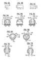
- FIGS. 6A and 6Bare end section views of an alternative embodiment of an article-orienting unit according to the present invention that enables the size of the opening therein to be adjusted.
- FIGS. 7A and 7Bare end section views of another embodiment of an article-orienting unit according to the present invention.
- FIG. 8is a flow chart illustrating a method of singulating articles according to the present invention.
- the device 10includes a bulk article housing 11 in which a plurality of small articles A are suspended in fluidized motion.
- the housing 11includes a surrounding wall 12 , a floor 13 , and a ceiling 14 .
- the wall 12may be continuous or segmented (i.e., it may comprise multiple contiguous walls), may have a door 12 a filling for access for articles A, and is preferably transparent to allow visual access to the articles A contained therein.
- the floor 13 and ceiling 14may smoothly merge with the wall 12 or may form distinct corners therewith.
- housings of many shapes and configurationsmay be suitable for use with the present invention.
- the floor 13includes a screen 15 or other foraminous member that allows air passage into the housing 11 but not passage of the articles A out.
- the ceiling 14includes a screen 16 or other foraminous member that functions to keep articles A in, but allow air passage; in this instance the air flows out of the housing 11 .
- a blower 17 or other device for inducing airflowis attached to a low pressure plenum 17 a mounted above the screen 16 . The blower 17 is included to create a negative pressure differential with respect to ambient air pressure by drawing air from outside the housing through the screen 15 , into the cavity of the housing 11 , and out through the screen 16 .
- the illustrated embodimentalso includes a jet nozzle 18 or other jet aperture located on the wall 12 .
- the jet nozzle 18is oriented to direct a jet into the housing 11 toward an exit channel 20 located opposite the housing from the jet nozzle 18 .
- Access to the nozzle 18is controlled by a valve 18 a , which is fluidly attached to a positive pressure source 28 (described in detail below).
- the exit channel 20extends away from the housing 11 opposite the jet nozzle 18 .
- An article-orienting unit 30is located at the mouth of the exit channel 20 to singulate articles A entering the exit channel 20 .
- the exit channel 20includes a primary lumen 21 that extends downstream from the article-orienting unit 30 to terminate at an outlet 22 .
- the lumen 21defines a downstream flow path P therein.
- downstreammeans the direction that articles A travel in moving from the housing 11 to the outlet 22 .
- upstreammeans the direction opposite the downstream direction. It should be noted that, relative to an absolute x-y-z coordinate axis system, these directions may shift as articles A move in the exit channel 20 (for example, in the illustrated embodiment, the articles A move directly away from the housing 11 , then turn downwardly).
- the “longitudinal” dimension of a structure or componentis intended to be parallel with the downstream direction, and the “transverse” dimension of a structure or component is intended to be normal to the downstream direction.
- the lumen 21has a cross-section that permits the passage of only one article at a time; i.e., two or more articles may not travel in the lumen 21 side-by-side.
- the lumenhas a cross-section that generally resembles, but is somewhat larger than, that of the transverse cross-section of an article A traveling in the lumen 21 .
- the lumen 21 of the channel 20can be sized to be generally rectangular in cross section, with a height or width dimension slightly smaller than two minimum dimensions ⁇ of the articles A (see FIGS. 4A and 4C ) to prevent the simultaneous passage of two articles A.
- a forward jet pressure chamber 24 and a rear pressure jet chamber 25are mounted to the exit channel 20 .
- the forward jet pressure chamber 24is in fluid communication with the lumen 21 via a pair of forward jet apertures 26 a , 26 b , each of which is oriented at an angle (preferably between about 1 and 89 degrees, and more preferably between 5 and 50 degrees) relative to the longitudinal axis of the lumen 21 such that a jet exiting the forward jet apertures 26 a , 26 b enhances flow in the lumen 21 toward the outlet 22 .
- the rear pressure jet chamber 25is in fluid communication with the lumen 21 via a rear jet aperture 27 , which is oriented at an angle (preferably between about 1 and 89 degrees, and more preferably between 5 and 50 degrees) relative to the longitudinal axis of the lumen 21 such that a jet exiting the rear jet aperture 27 impedes flow in lumen 21 toward the outlet 22 .
- a rear jet aperture 27which is oriented at an angle (preferably between about 1 and 89 degrees, and more preferably between 5 and 50 degrees) relative to the longitudinal axis of the lumen 21 such that a jet exiting the rear jet aperture 27 impedes flow in lumen 21 toward the outlet 22 .
- any or all of the forwardly and rearwardly-directed aperturesmay be arranged in combinations of any number.
- a common pressure source 28is attached to each of the forward and rear pressure jet chambers 24 , 25 and, as noted above, the jet nozzle 18 .
- the pressureis each chamber 24 , 25 , 18 is regulated by a respective valve 29 a , 29 b , 18 a .
- Those skilled in this artwill recognize that the pressure in each chamber 24 , 25 , 18 , or in fact each jet aperture 26 a , 26 b , 27 , 18 , may be controlled by a separate pressure source.
- these pressure sourcesmay be common (i.e., coincident) sources, or any or all of these may be separate sources.
- An article sensor 23is positioned near the outlet 22 and is configured to count passing articles A as they travel through the lumen 21 .
- Exemplary sensorsinclude an opposing LED/photo-transistor pair and reflective, capacitive, or mechanical switches.
- a controller 40is operatively connected with the valves 29 a , 29 b , 18 a and with the sensor 23 . The controller 40 causes the valves 29 a , 29 b , 18 a to open or close depending on the number of articles A that have been counted by the sensor 23 at any particular point in time.
- the controller 40can be any number of controller units known to those skilled in this art as being suitable for receiving signals from the sensor 23 and transmitting operating signals to the valves 29 a , 29 b , 18 a ; an exemplary controller is the 87518-bit micro controller, available from Intel. It should be recognized that the controller 40 may be connected directly to the pressure source 28 (or any other pressure sources in embodiments in which multiple pressure sources are employed) to activate them directly rather than operating the valves.
- the article-orienting unit 30has a pair of generally parallel, spaced panels 31 a , 31 b and a third panel 32 that is generally perpendicular to the panels 31 a , 31 b .
- the downstream ends of these panels 31 a , 31 b , 32abut the mouth of the exit channel 20 and their upstream ends extend slightly upstream into the housing 11 .
- the downstream ends of one or all of the aforementioned panelsmay extend most or all the entire length of the lumen 21 , ensuring that only one article A at a time may pass therein.
- the panels 31 a , 31 bare spaced apart a distance a, and the panel 32 is spaced from an upstream portion 20 a of the exit channel 20 a distance b, thereby defining an entry space E of the dimensions a ⁇ b for the articles A.
- the article-orienting unit 30is particularly suited for the singulation of articles A that are oblong or oblate, with a longest longitudinal dimension ⁇ , a shortest transverse dimension ⁇ , and an intermediate transverse dimension ⁇ that is greater than ⁇ but less than or equal to ⁇ (see FIGS. 4A-4C ).
- the distance ais greater than ⁇ but less than the smaller of ⁇ and two times ⁇ .
- the distance bis greater than ⁇ but less than the smaller of ⁇ and two times ⁇ .
- the articles Acan fit in the entry space E in only one orientation (that shown in FIG. 5A , in which the dimension ⁇ is generally parallel to the distance a).
- the distance ais greater than ⁇ and ⁇ , but is less than two times ⁇ .
- the distance bis greater than ⁇ but is less than the smaller of ⁇ and two times ⁇ .
- the article Acan fit in the entry space E in any orientation in which ⁇ is perpendicular to the distances a, b of the entry space E.
- an alternative article-orienting unitshould be chosen to prevent more than one article A entering the exit channel 20 at once.
- objects whose three dimensions are substantially equali.e. spheres
- Exemplary articlesinclude comestibles such as candies and breath mints, machine components sucha as bolts, nuts and other fasteners, valuables such as diamonds and other gemstones, vitamins, and the like. It may also be understood that an article-orienting device may be attached at the outlet 22 , with the result that the device 10 may singulate in both directions.
- the device 10begins with the valves 29 a , 29 b of the forward and rear jet chambers 24 , 25 closed (as directed by the controller 40 ), such that the pressure source 28 does not provide jets through the jet apertures 26 a , 26 b , 27 or through the jet aperture 18 a (see FIG. 3A and Block 200 of FIG. 8 ).
- the blower 17is activated and creates a low-level negative pressure with respect to ambient air pressure, causing ambient air to be drawn into the housing 11 through the bottom screen 15 and onto the articles A, thereby suspending (agitating or fluidizing) them. The air then passes out through the top screen 16 and past the blower 17 . This agitation gives the articles A fluid flow characteristics within the housing 11 (Block 210 ).
- the individual articles Atravel randomly about the interior of the housing 11 , or can be made to mimic specific fluid flow patterns if desired.
- airflowis established from the exterior of the device 10 backward through the exit channel 20 , inward to the housing 11 , and out the top screen 16 to the blower 17 . This airflow pattern prevents articles A from spilling out of the housing 11 into the exit channel 20 .
- articles in the housingmay be mechanically agitated through known techniques.
- the controller 40When the controller 40 requests the dispensing and counting of articles, the controller 40 signals the forward jet chamber valve 29 a to open, and a forwardly-directed air jet is generated through the forward jet apertures 26 a , 26 b (see FIG. 3B and Block 220 of FIG. 8 ).
- This activitycreates a net outward flow of air from the housing 11 through the exit channel 20 .
- the jetsapply a pressure of between about 1 and 500 pounds per square inch into the exit channel 20 .
- variable pressure control methodsmay be used for a given pressure pulse through a jet, depending on the effect desired (for example to match the impedance of the object in the channel), including simple square waves, sawtooth, sinusoidal, or complex pressure waveforms.
- the controller 40may signal the valve 18 a to open so that the jet nozzle 18 emits a jet (preferably of about 1 to 500 psi) that urges articles toward and through the exit channel 20 (Block 230 of FIG. 8 ).
- a jetpreferably of about 1 to 500 psi
- the controller 40may signal the valve 18 a to open so that the jet nozzle 18 emits a jet (preferably of about 1 to 500 psi) that urges articles toward and through the exit channel 20 (Block 230 of FIG. 8 ).
- a jetpreferably of about 1 to 500 psi
- the controller 40may signal the valve 18 a to open so that the jet nozzle 18 emits a jet (preferably of about 1 to 500 psi) that urges articles toward and through the exit channel 20 (Block 230 of FIG. 8 ).
- a vacuumis induced at the entry space E, with the result that articles A within the influence of this induced airflow are drawn to the article-orienting unit 30 .
- the article-orienting unit 30is sized and configured so that only one article A can pass through the article-orienting unit 30 at a time. Consequently, articles A enter the exit channel as an endwise (or edgewise), single-file stream.
- the sensors 23As the articles A continue through the exit channel 20 , they pass the sensor 23 , where the articles A are detected and counted (Block 260 of FIG. 8 ).
- the increased interval created by the multiple acceleration stagesencourages accurate counting of the articles A.
- the inability of the exit channel 20 to permit the passage of more than one article A at a time at any single point in the exit channel 20i.e., the articles A cannot pass “side-by-side” through the exit channel 20 ) also assists the sensor 23 in distinguishing one article A from the next.
- the sensor 23signals the controller 40 with the passage of each article A so that the controller 40 can count the number of articles A that have passed thereby and compare that number to a predetermined number (Block 270 of FIG. 8 ).
- the senor 23be positioned downstream of the forwardly-directed jet apertures 26 a , 26 b , other locations for the sensor 23 on the exit channel 20 may also be suitable for use with the present invention, and that more than one sensor may be used.
- the controller 40determines that a predetermined number of articles has passed the sensor 23 , at which point the controller 40 signals the valve 29 a to close, which deactivates the forward jets (Block 280 of FIG. 8 ), and signals the valve 29 b to open to generate a reverse jet from the rear jet aperture 27 (see FIG. 3C and Block 290 of FIG. 8 ).
- the controller 40also signals the valve 18 a if present to close in order to cease the production of the jet from the nozzle 18 .
- the momentum of the articles A that have passed the sensor 23propels them out of the exit channel 20 and into the receiving container.
- Articles A that have not yet reached the sensor 23however, reverse direction due to the reverse flow created by both the reverse jet and the sub-ambient pressure generated by the blower 17 . Consequently, they return to the housing 11 through the article-orienting unit 30 (aided by the fact that the cross-section of the lumen 21 of the exit channel 20 prevents the articles A from re-orienting). This reversal of direction of the articles A is also assisted by the interval created by the multiple acceleration stages described earlier. In some embodiments, the housing 11 may even be filled with articles A through the outlet 22 via the suction provided by the blower 17 and the rearward jet 27 .
- controller 40may be used to detect jams at the entrance to the exit channel (by dint of the lack of passage signals at sensor 23 ) and so the forward and reverse jets may be pulsed off and on to clear the jam. Typically, this is will reduce the overall speed of the system but that may be an acceptable trade in certain applications.
- the article-orienting unit 30 ′may take the configuration of that illustrated in FIGS. 7A and 7B , which lacks a plate 32 .
- the configuration of an article-orienting unit 100 shown in FIGS. 6A and 6Bis also suitable.
- the article-orienting unit 100includes a pair of hinged panels 110 that pivot about a pivot axis 111 that is parallel with the flow axis of the exit channel 20 .
- the hinged panels 110 and the wall 20 a of the exit channel 20define an entry space E′ that is generally wedge-shaped and that can, depending on the shape of the article A, only permit a single article A to pass therethrough at a time, and to do so in a preferred orientation.
- the downstream ends of the panels 110may extend most or all the entire length of the lumen 21 .
- One advantage of this configurationis the capability of one or both of the panels 110 to pivot relative to one another to adjust the size of the entry space available to the article A, thereby enabling the device 100 to be used on batches of articles that vary in size from batch to batch.
Landscapes
- Engineering & Computer Science (AREA)
- Mechanical Engineering (AREA)
- Physics & Mathematics (AREA)
- Fluid Mechanics (AREA)
- Animal Behavior & Ethology (AREA)
- General Health & Medical Sciences (AREA)
- Public Health (AREA)
- Veterinary Medicine (AREA)
- Health & Medical Sciences (AREA)
- Life Sciences & Earth Sciences (AREA)
- Filling Or Emptying Of Bunkers, Hoppers, And Tanks (AREA)
- Vending Machines For Individual Products (AREA)
- Basic Packing Technique (AREA)
- Supply Of Fluid Materials To The Packaging Location (AREA)
- Feeding Of Articles To Conveyors (AREA)
- Image Processing (AREA)
Abstract
Description
Claims (1)
Priority Applications (1)
| Application Number | Priority Date | Filing Date | Title |
|---|---|---|---|
| US10/685,260US8651326B2 (en) | 2001-07-20 | 2003-10-14 | Device to count and dispense articles |
Applications Claiming Priority (3)
| Application Number | Priority Date | Filing Date | Title |
|---|---|---|---|
| US30678201P | 2001-07-20 | 2001-07-20 | |
| US09/934,940US6631826B2 (en) | 2001-07-20 | 2001-08-22 | Device to count and dispense articles |
| US10/685,260US8651326B2 (en) | 2001-07-20 | 2003-10-14 | Device to count and dispense articles |
Related Parent Applications (1)
| Application Number | Title | Priority Date | Filing Date |
|---|---|---|---|
| US09/934,940ContinuationUS6631826B2 (en) | 2001-07-20 | 2001-08-22 | Device to count and dispense articles |
Publications (2)
| Publication Number | Publication Date |
|---|---|
| US20040159669A1 US20040159669A1 (en) | 2004-08-19 |
| US8651326B2true US8651326B2 (en) | 2014-02-18 |
Family
ID=26975350
Family Applications (2)
| Application Number | Title | Priority Date | Filing Date |
|---|---|---|---|
| US09/934,940Expired - LifetimeUS6631826B2 (en) | 2001-07-20 | 2001-08-22 | Device to count and dispense articles |
| US10/685,260Expired - Fee RelatedUS8651326B2 (en) | 2001-07-20 | 2003-10-14 | Device to count and dispense articles |
Family Applications Before (1)
| Application Number | Title | Priority Date | Filing Date |
|---|---|---|---|
| US09/934,940Expired - LifetimeUS6631826B2 (en) | 2001-07-20 | 2001-08-22 | Device to count and dispense articles |
Country Status (9)
| Country | Link |
|---|---|
| US (2) | US6631826B2 (en) |
| EP (1) | EP1409381B1 (en) |
| JP (1) | JP4027891B2 (en) |
| KR (1) | KR100728814B1 (en) |
| AT (1) | ATE328823T1 (en) |
| BR (1) | BR0211294B1 (en) |
| CA (2) | CA2658044C (en) |
| DE (1) | DE60212139T2 (en) |
| WO (1) | WO2003008308A1 (en) |
Cited By (6)
| Publication number | Priority date | Publication date | Assignee | Title |
|---|---|---|---|---|
| US20120111418A1 (en)* | 2010-11-08 | 2012-05-10 | Lishun Hu | Pipelines and conveying methods |
| US20180056460A1 (en)* | 2016-08-31 | 2018-03-01 | InFocus Industrial System Limited | Spring separating and feeding device and method thereof |
| US20180141689A1 (en)* | 2015-07-18 | 2018-05-24 | Harro Hoefliger Verpackungsmaschinen Gmbh | Method and device for separating and transferring pellets |
| US20190016522A1 (en)* | 2015-06-01 | 2019-01-17 | Jason Littman | Selectively Changeable, Volumetric Dispensers And Methods of Dispensing Materials Having Known Unit Volumes |
| US11345544B2 (en) | 2019-03-29 | 2022-05-31 | Mckesson Corporation | Apparatuses, systems, and methods for the automated retrieval and dispensing of articles |
| US11386390B2 (en) | 2016-11-01 | 2022-07-12 | Mckesson Corporation | Central fill facility and associated drug dispensing system and method |
Families Citing this family (50)
| Publication number | Priority date | Publication date | Assignee | Title |
|---|---|---|---|---|
| US6971541B2 (en)* | 2002-05-14 | 2005-12-06 | Parata Systems, Inc. | System and method for dispensing prescriptions |
| US7228198B2 (en) | 2002-08-09 | 2007-06-05 | Mckesson Automation Systems, Inc. | Prescription filling apparatus implementing a pick and place method |
| US7303094B2 (en) | 2002-08-09 | 2007-12-04 | Kevin Hutchinson | Vacuum pill dispensing cassette and counting machine |
| EP1535251A2 (en)* | 2002-08-09 | 2005-06-01 | Mckesson Automation Systems, Inc. | Dispensing device having a storage chamber, dispensing chamber and a feed regulator there between |
| DE102004006411B4 (en) | 2004-02-09 | 2018-09-20 | Volkswagen Ag | Method and device for providing fastening means arranged in a loading device in a specific orientation |
| US8020724B2 (en) | 2004-03-15 | 2011-09-20 | Parata Systems, Llc | Vacuum based pill singulator and counter based thereon |
| US7726514B2 (en)* | 2004-07-07 | 2010-06-01 | Rxmedic Systems, Inc. | Automated article dispensation mechanism |
| JP2006100484A (en)* | 2004-09-29 | 2006-04-13 | Taiyo Yuden Co Ltd | Component supply apparatus |
| US7344049B2 (en)* | 2005-04-21 | 2008-03-18 | Parata Systems, L.L.C. | Devices useful in system and method for dispensing prescriptions |
| CA2624243C (en) | 2005-09-29 | 2013-12-31 | Siemens Medical Solutions Usa, Inc. | Microfluidic chip for synthesizing radioactively labeled molecules suitable for human imaging with positron emission tomography |
| US7853355B1 (en) | 2006-07-07 | 2010-12-14 | Waldemar Willemse | Pharmaceutical dispensing system for medicament and pre-packaged medication |
| US8078329B2 (en)* | 2006-09-29 | 2011-12-13 | Courtoy Nv | System for rejection of tablets produced in a rotary tablet press and a method of rejection of tablets |
| US20080093372A1 (en)* | 2006-10-23 | 2008-04-24 | Milton Monroe T | Method and apparatus for sorting, counting and packaging pharmaceutical drugs and other objects |
| US20080110555A1 (en)* | 2006-11-14 | 2008-05-15 | Steve Bouchelle | Device and method for labeling vials useful in system for dispensing prescriptions |
| US8261936B2 (en) | 2006-11-14 | 2012-09-11 | Parata Systems, Llc | Device for dispensing vials useful in system and method for dispensing prescriptions |
| US7596932B2 (en)* | 2007-01-17 | 2009-10-06 | Parata Systems, Llc | Devices for capping vials useful in system and method for dispensing prescriptions |
| US8056760B2 (en)* | 2007-01-22 | 2011-11-15 | Parata Systems, Llc | Cap dispensing devices useful in system and method for dispensing prescriptions |
| US20080245810A1 (en)* | 2007-04-05 | 2008-10-09 | Parata Systems, Llc | Methods and apparatus for dispensing solid pharmaceutical articles |
| US7837061B2 (en)* | 2007-05-18 | 2010-11-23 | Parata Systems, Llc | Methods and apparatus for dispensing solid pharmaceutical articles |
| US7949427B2 (en) | 2007-05-18 | 2011-05-24 | Parata Systems, Llc | Methods and apparatus for dispensing solid articles |
| US7988017B2 (en)* | 2007-05-18 | 2011-08-02 | Parata Systems, Llc | Methods and apparatus for dispensing solid pharmaceutical articles |
| US7832591B2 (en)* | 2007-05-18 | 2010-11-16 | Parata Systems, Llc | Methods and apparatus for dispensing solid pharmaceutical articles |
| EP2188181A1 (en)* | 2007-08-09 | 2010-05-26 | Aylward Enterprises, LLC | Packaging apparatus for handling pills and associated method |
| US8714405B2 (en)* | 2007-08-10 | 2014-05-06 | Parata Systems, Llc | Device for staging and dispensing tablets useful in system and method for dispensing prescriptions |
| CA2607537A1 (en)* | 2007-10-22 | 2009-04-22 | Ibm Canada Limited - Ibm Canada Limitee | Software engineering system and method for self-adaptive dynamic software components |
| US7870973B2 (en)* | 2008-01-09 | 2011-01-18 | Parata Systems, Llc | Methods and apparatus for dispensing solid articles |
| US8616409B2 (en)* | 2008-01-16 | 2013-12-31 | Parata Systems, Llc | Devices for dispensing objects useful in system and method for dispensing |
| US8464901B2 (en) | 2008-05-05 | 2013-06-18 | Parata Systems, Llc | Methods and apparatus for dispensing solid articles |
| US8827113B2 (en) | 2008-05-30 | 2014-09-09 | Parata Systems, Llc | Methods and apparatus for dispensing solid articles |
| US8499967B2 (en)* | 2008-07-14 | 2013-08-06 | Parata Systems, Llc | Methods and apparatus for dispensing solid articles |
| US8271128B1 (en)* | 2008-07-30 | 2012-09-18 | Kirby Lester, Llc | Pharmacy workflow management system including plural counters |
| US8424274B2 (en) | 2008-11-07 | 2013-04-23 | Aylward Enterprises, Llc | Packaging apparatus for handling pills and associated method |
| US8054086B2 (en)* | 2009-06-25 | 2011-11-08 | Parata Systems, Llc | Apparatus for dispensing and detecting solid pharmaceutical articles and related methods of operation |
| WO2011003078A1 (en) | 2009-07-02 | 2011-01-06 | Kinze Manufacturing, Inc. | Air entrainment device for seed delivery |
| US8417375B2 (en) | 2010-05-13 | 2013-04-09 | Data Detection Technologies Ltd. | Counting machine for discrete items |
| US8777054B2 (en) | 2011-01-21 | 2014-07-15 | Parata Systems, Llc | Apparatus for dispensing solid articles and methods for using same |
| US8977390B2 (en) | 2011-08-23 | 2015-03-10 | Vendrx, Inc. | Systems and methods for dispensing beneficial products |
| US10102706B2 (en) | 2011-08-23 | 2018-10-16 | Vendrx, Inc. | Beneficial product dispenser |
| GB2486939B (en) | 2011-12-01 | 2012-11-21 | Data Detection Technologies Ltd | Method and apparatus for dispensing items |
| CN102674009A (en)* | 2012-05-18 | 2012-09-19 | 昆山诚业德精密模具有限公司 | Blowing and feeding device for shielding cover |
| US9296545B2 (en) | 2012-11-20 | 2016-03-29 | Parata Systems, Llc | Methods and apparatus for dispensing solid articles |
| GB201308935D0 (en)* | 2013-05-17 | 2013-07-03 | Slovick David | Counting head for dispensing pharmaceutical substances |
| US20140361031A1 (en)* | 2013-06-11 | 2014-12-11 | Parata Systems, Llc | Methods and apparatus for dispensing solid pharmaceutical articles using capacitive level sensors |
| CN103848121B (en)* | 2014-04-01 | 2016-01-06 | 苏州润弘贸易有限公司 | Three pipeline double-head counting grain machines |
| US11304356B2 (en)* | 2015-06-08 | 2022-04-19 | Monsanto Technology Llc | High throughput cassette filler |
| CN105015839A (en)* | 2015-06-12 | 2015-11-04 | 吴俊娟 | Automatic tablet counter |
| US11220361B2 (en) | 2018-10-12 | 2022-01-11 | Aylward Enterprises, Llc | Packaging apparatus for handling pills and associated method |
| UA127748C2 (en) | 2018-11-13 | 2023-12-20 | Кінз Меньюфекчуринг, Інк. | Air entrainment device, systems, methods, and apparatus |
| US11305908B2 (en) | 2019-09-20 | 2022-04-19 | Aylward Enterprises, Llc | Tablet counter and packaging module and associated method |
| US11594094B2 (en) | 2020-01-22 | 2023-02-28 | Parata Systems, Llc | Methods and apparatus for dispensing solid articles |
Citations (37)
| Publication number | Priority date | Publication date | Assignee | Title |
|---|---|---|---|---|
| US3414111A (en)* | 1967-03-08 | 1968-12-03 | Penn Eng & Mfg Corp | Feed hopper having adjustable article orienting means |
| US3722674A (en) | 1971-04-19 | 1973-03-27 | Hoppmann Corp | Apparatus for sorting particulate articles |
| US3730388A (en) | 1972-02-10 | 1973-05-01 | Brenner & Bender Inc | Material measuring and dispensing apparatus |
| US3789194A (en) | 1970-09-08 | 1974-01-29 | Kirby Lester Electronics Ltd | Relating to counting machines |
| US3843018A (en) | 1970-06-26 | 1974-10-22 | Research Corp | Pneumatic metering device |
| US3958687A (en) | 1974-10-09 | 1976-05-25 | Hoffmann-La Roche Inc. | High-speed multi-channel feeder for tablets |
| US4014429A (en)* | 1975-11-17 | 1977-03-29 | Tangen Drives, Inc. | Parts feeder and orienter with induction ring feed nozzle |
| US4223751A (en)* | 1979-03-26 | 1980-09-23 | Modern Controls, Inc. | High speed capacitance apparatus for classifying pharmaceutical capsules |
| US4466554A (en) | 1982-04-01 | 1984-08-21 | Bud Antle, Inc. | Singulating seeder for high density plug trays |
| US4769904A (en)* | 1985-08-02 | 1988-09-13 | Universal Instruments Corporation | Method and apparatus for handling leaded and leadless surface mountable components |
| US4828142A (en)* | 1986-01-24 | 1989-05-09 | Eli Lilly & Company | Capsule rectification apparatus |
| US4869394A (en) | 1986-04-28 | 1989-09-26 | Hurst Kerney J | Article counting device |
| US4953749A (en) | 1986-05-27 | 1990-09-04 | Nitto Kogyo Kabushiki Kaisha | Chip separation and alignment apparatus |
| GB2244481A (en) | 1990-05-31 | 1991-12-04 | Taiyo Yuden Kk | Supplying parts from hopper |
| US5082141A (en) | 1990-05-03 | 1992-01-21 | The United States Of America As Represented By The Secretary Of Agriculture | Device for singulating particles |
| US5083141A (en)* | 1989-08-30 | 1992-01-21 | Ricoh Company, Ltd. | Image forming apparatus |
| US5317645A (en) | 1991-02-28 | 1994-05-31 | Kirby Lester Inc. | Method and apparatus for the recognition and counting of discrete objects |
| US5337919A (en) | 1993-02-11 | 1994-08-16 | Dispensing Technologies, Inc. | Automatic dispensing system for prescriptions and the like |
| US5385434A (en)* | 1992-12-09 | 1995-01-31 | Molex Incorporated | Electrical connector delivery system |
| US5463839A (en) | 1994-08-04 | 1995-11-07 | The Lakso Company | Apparatus for packaging a predetermined quantity of objects and a counting device therefor |
| US5671262A (en) | 1996-05-06 | 1997-09-23 | Innovation Associates, Inc. | Method for counting and dispensing tablets, capsules, and pills |
| US5713487A (en) | 1996-03-11 | 1998-02-03 | Scriptpro L.L.C. | Medicament verification in an automatic dispening system |
| US5725160A (en)* | 1995-09-14 | 1998-03-10 | Saf-T-Source, Inc. | Chip blower apparatus |
| US5774518A (en) | 1997-01-30 | 1998-06-30 | Kirby; John | Discrete tablet counting machine |
| JPH11171323A (en)* | 1997-12-09 | 1999-06-29 | Taiyo Yuden Co Ltd | Part conveying mechanism, part take-in mechanism and part separating mechanism for chip part supplying device |
| US6006946A (en) | 1997-12-05 | 1999-12-28 | Automated Prescriptions System, Inc. | Pill dispensing system |
| US6036812A (en) | 1997-12-05 | 2000-03-14 | Automated Prescription Systems, Inc. | Pill dispensing system |
| US6039512A (en) | 1997-09-18 | 2000-03-21 | Chooi; Kon Hing | Feeder system and method for supplying electrical components to a pickup location |
| US6053302A (en) | 1999-02-10 | 2000-04-25 | Geometric Controls Inc. | Object singulating and counting device |
| US6116821A (en)* | 1998-08-03 | 2000-09-12 | Motorola Malaysia Sdn Bhd | Feeder system and method for supplying electrical components to a pick up location |
| US6170229B1 (en) | 1998-07-14 | 2001-01-09 | Jin Soo Kim | Tablet cassette for automatic tablet sorting and counting machine |
| US6176393B1 (en) | 1999-06-22 | 2001-01-23 | Deere & Company | Seed meter for small grain |
| US6176392B1 (en) | 1997-12-05 | 2001-01-23 | Mckesson Automated Prescription Systems, Inc. | Pill dispensing system |
| US6182718B1 (en) | 1999-06-15 | 2001-02-06 | Summit Machine Builders, Corp. | Pass-through dispenser system with aligned feeder troughs |
| US6201848B1 (en) | 1999-06-22 | 2001-03-13 | Count On Us, Corporation | Article counter with improved light beam coverage |
| US6208911B1 (en) | 1996-12-27 | 2001-03-27 | Sanyo Electric Co., Ltd. | Solid drug filling apparatus |
| USRE37829E1 (en) | 1990-12-06 | 2002-09-03 | Automed Technologies, Inc. | Automated prescription vial filling system |
Family Cites Families (2)
| Publication number | Priority date | Publication date | Assignee | Title |
|---|---|---|---|---|
| DE931557C (en) | 1951-05-11 | 1955-08-11 | Georges Dr Lunin | Device for introducing similar workpieces contained in a collecting container into a profile channel |
| US5317919A (en)* | 1992-06-16 | 1994-06-07 | Teledyne Industries, Inc. | A precision capacitor sensor |
- 2001
- 2001-08-22USUS09/934,940patent/US6631826B2/ennot_activeExpired - Lifetime
- 2002
- 2002-07-19CACA2658044Apatent/CA2658044C/ennot_activeExpired - Lifetime
- 2002-07-19DEDE60212139Tpatent/DE60212139T2/ennot_activeExpired - Lifetime
- 2002-07-19BRBRPI0211294-9Apatent/BR0211294B1/ennot_activeIP Right Cessation
- 2002-07-19WOPCT/US2002/023307patent/WO2003008308A1/enactiveIP Right Grant
- 2002-07-19JPJP2003513877Apatent/JP4027891B2/ennot_activeExpired - Fee Related
- 2002-07-19ATAT02747076Tpatent/ATE328823T1/ennot_activeIP Right Cessation
- 2002-07-19EPEP02747076Apatent/EP1409381B1/ennot_activeExpired - Lifetime
- 2002-07-19CACA002453404Apatent/CA2453404C/ennot_activeExpired - Lifetime
- 2002-07-19KRKR1020047000060Apatent/KR100728814B1/ennot_activeExpired - Fee Related
- 2003
- 2003-10-14USUS10/685,260patent/US8651326B2/ennot_activeExpired - Fee Related
Patent Citations (40)
| Publication number | Priority date | Publication date | Assignee | Title |
|---|---|---|---|---|
| US3414111A (en)* | 1967-03-08 | 1968-12-03 | Penn Eng & Mfg Corp | Feed hopper having adjustable article orienting means |
| US3843018A (en) | 1970-06-26 | 1974-10-22 | Research Corp | Pneumatic metering device |
| US3789194A (en) | 1970-09-08 | 1974-01-29 | Kirby Lester Electronics Ltd | Relating to counting machines |
| US3722674A (en) | 1971-04-19 | 1973-03-27 | Hoppmann Corp | Apparatus for sorting particulate articles |
| US3730388A (en) | 1972-02-10 | 1973-05-01 | Brenner & Bender Inc | Material measuring and dispensing apparatus |
| US3958687A (en) | 1974-10-09 | 1976-05-25 | Hoffmann-La Roche Inc. | High-speed multi-channel feeder for tablets |
| US4014429A (en)* | 1975-11-17 | 1977-03-29 | Tangen Drives, Inc. | Parts feeder and orienter with induction ring feed nozzle |
| US4223751A (en)* | 1979-03-26 | 1980-09-23 | Modern Controls, Inc. | High speed capacitance apparatus for classifying pharmaceutical capsules |
| US4466554A (en) | 1982-04-01 | 1984-08-21 | Bud Antle, Inc. | Singulating seeder for high density plug trays |
| US4769904A (en)* | 1985-08-02 | 1988-09-13 | Universal Instruments Corporation | Method and apparatus for handling leaded and leadless surface mountable components |
| US4828142A (en)* | 1986-01-24 | 1989-05-09 | Eli Lilly & Company | Capsule rectification apparatus |
| US4869394A (en) | 1986-04-28 | 1989-09-26 | Hurst Kerney J | Article counting device |
| US4953749A (en) | 1986-05-27 | 1990-09-04 | Nitto Kogyo Kabushiki Kaisha | Chip separation and alignment apparatus |
| US5083141A (en)* | 1989-08-30 | 1992-01-21 | Ricoh Company, Ltd. | Image forming apparatus |
| US5082141A (en) | 1990-05-03 | 1992-01-21 | The United States Of America As Represented By The Secretary Of Agriculture | Device for singulating particles |
| GB2244481A (en) | 1990-05-31 | 1991-12-04 | Taiyo Yuden Kk | Supplying parts from hopper |
| USRE37829E1 (en) | 1990-12-06 | 2002-09-03 | Automed Technologies, Inc. | Automated prescription vial filling system |
| US5473703A (en) | 1991-02-28 | 1995-12-05 | Kirby Lester, Inc. | Methods and apparatus for controlling the feed rate of a discrete object sorter/counter |
| US5317645A (en) | 1991-02-28 | 1994-05-31 | Kirby Lester Inc. | Method and apparatus for the recognition and counting of discrete objects |
| US5385434A (en)* | 1992-12-09 | 1995-01-31 | Molex Incorporated | Electrical connector delivery system |
| US5337919A (en) | 1993-02-11 | 1994-08-16 | Dispensing Technologies, Inc. | Automatic dispensing system for prescriptions and the like |
| US5463839A (en) | 1994-08-04 | 1995-11-07 | The Lakso Company | Apparatus for packaging a predetermined quantity of objects and a counting device therefor |
| US5725160A (en)* | 1995-09-14 | 1998-03-10 | Saf-T-Source, Inc. | Chip blower apparatus |
| US5713487A (en) | 1996-03-11 | 1998-02-03 | Scriptpro L.L.C. | Medicament verification in an automatic dispening system |
| US5762235A (en) | 1996-03-11 | 1998-06-09 | Scriptpro, L.L.C. | Medicament verification in an automatic dispensing system |
| US5671262A (en) | 1996-05-06 | 1997-09-23 | Innovation Associates, Inc. | Method for counting and dispensing tablets, capsules, and pills |
| US6208911B1 (en) | 1996-12-27 | 2001-03-27 | Sanyo Electric Co., Ltd. | Solid drug filling apparatus |
| US5774518A (en) | 1997-01-30 | 1998-06-30 | Kirby; John | Discrete tablet counting machine |
| US6039512A (en) | 1997-09-18 | 2000-03-21 | Chooi; Kon Hing | Feeder system and method for supplying electrical components to a pickup location |
| US6036812A (en) | 1997-12-05 | 2000-03-14 | Automated Prescription Systems, Inc. | Pill dispensing system |
| US6176392B1 (en) | 1997-12-05 | 2001-01-23 | Mckesson Automated Prescription Systems, Inc. | Pill dispensing system |
| US6006946A (en) | 1997-12-05 | 1999-12-28 | Automated Prescriptions System, Inc. | Pill dispensing system |
| US6443326B1 (en)* | 1997-12-09 | 2002-09-03 | Taiyo Yuden Co., Ltd. | Electronic component feeding apparatus |
| JPH11171323A (en)* | 1997-12-09 | 1999-06-29 | Taiyo Yuden Co Ltd | Part conveying mechanism, part take-in mechanism and part separating mechanism for chip part supplying device |
| US6170229B1 (en) | 1998-07-14 | 2001-01-09 | Jin Soo Kim | Tablet cassette for automatic tablet sorting and counting machine |
| US6116821A (en)* | 1998-08-03 | 2000-09-12 | Motorola Malaysia Sdn Bhd | Feeder system and method for supplying electrical components to a pick up location |
| US6053302A (en) | 1999-02-10 | 2000-04-25 | Geometric Controls Inc. | Object singulating and counting device |
| US6182718B1 (en) | 1999-06-15 | 2001-02-06 | Summit Machine Builders, Corp. | Pass-through dispenser system with aligned feeder troughs |
| US6176393B1 (en) | 1999-06-22 | 2001-01-23 | Deere & Company | Seed meter for small grain |
| US6201848B1 (en) | 1999-06-22 | 2001-03-13 | Count On Us, Corporation | Article counter with improved light beam coverage |
Cited By (8)
| Publication number | Priority date | Publication date | Assignee | Title |
|---|---|---|---|---|
| US20120111418A1 (en)* | 2010-11-08 | 2012-05-10 | Lishun Hu | Pipelines and conveying methods |
| US9387997B2 (en)* | 2010-11-08 | 2016-07-12 | General Electric Company | Pipelines and conveying methods |
| US20190016522A1 (en)* | 2015-06-01 | 2019-01-17 | Jason Littman | Selectively Changeable, Volumetric Dispensers And Methods of Dispensing Materials Having Known Unit Volumes |
| US20180141689A1 (en)* | 2015-07-18 | 2018-05-24 | Harro Hoefliger Verpackungsmaschinen Gmbh | Method and device for separating and transferring pellets |
| US10556712B2 (en)* | 2015-07-18 | 2020-02-11 | Harro Hoefliger Verpackungsmaschinen Gmbh | Method and device for separating and transferring pellets |
| US20180056460A1 (en)* | 2016-08-31 | 2018-03-01 | InFocus Industrial System Limited | Spring separating and feeding device and method thereof |
| US11386390B2 (en) | 2016-11-01 | 2022-07-12 | Mckesson Corporation | Central fill facility and associated drug dispensing system and method |
| US11345544B2 (en) | 2019-03-29 | 2022-05-31 | Mckesson Corporation | Apparatuses, systems, and methods for the automated retrieval and dispensing of articles |
Also Published As
| Publication number | Publication date |
|---|---|
| WO2003008308A1 (en) | 2003-01-30 |
| DE60212139T2 (en) | 2007-04-05 |
| BR0211294B1 (en) | 2010-12-14 |
| CA2453404C (en) | 2009-06-16 |
| BR0211294A (en) | 2004-08-03 |
| CA2658044C (en) | 2012-09-18 |
| CA2453404A1 (en) | 2003-01-30 |
| KR20040023807A (en) | 2004-03-19 |
| WO2003008308A9 (en) | 2003-03-27 |
| ATE328823T1 (en) | 2006-06-15 |
| KR100728814B1 (en) | 2007-06-19 |
| US6631826B2 (en) | 2003-10-14 |
| US20040159669A1 (en) | 2004-08-19 |
| EP1409381B1 (en) | 2006-06-07 |
| DE60212139D1 (en) | 2006-07-20 |
| JP2004535344A (en) | 2004-11-25 |
| CA2658044A1 (en) | 2003-01-30 |
| EP1409381A1 (en) | 2004-04-21 |
| JP4027891B2 (en) | 2007-12-26 |
| US20030015555A1 (en) | 2003-01-23 |
Similar Documents
| Publication | Publication Date | Title |
|---|---|---|
| US8651326B2 (en) | Device to count and dispense articles | |
| US8833602B1 (en) | Apparatus for counting and dispensing pills using multi-staged pill singulation | |
| US9682016B1 (en) | Pill counting and dispensing apparatus with self-calibrating dispenser | |
| US11020771B2 (en) | Apparatus for sorting gemstones | |
| US8833603B1 (en) | Apparatus for counting and dispensing pills with a vibrating plate | |
| US8499967B2 (en) | Methods and apparatus for dispensing solid articles | |
| US20080245810A1 (en) | Methods and apparatus for dispensing solid pharmaceutical articles | |
| US20090173748A1 (en) | Methods and apparatus for dispensing solid articles | |
| US6370215B1 (en) | Apparatus for feeding, counting and dispensing discrete objects | |
| AU2002316746B2 (en) | Device to count and dispense articles | |
| US4901841A (en) | Parts sorter | |
| AU2002316746A1 (en) | Device to count and dispense articles | |
| US8849450B1 (en) | Aperture position control for pill counting and dispensing apparatus | |
| CA2073408C (en) | Fluidized bed bottle filling system | |
| US8880219B1 (en) | Apparatus for counting and dispensing pills using pill volume calculations | |
| JP2017119574A (en) | Hopper and article supply device | |
| JP2000163554A (en) | Dustproof mechanism and quick counter | |
| JP3735483B2 (en) | Alignment device | |
| JP2992672B2 (en) | Parts supply device | |
| SU1596361A1 (en) | Device for counting articles | |
| GB1587906A (en) | Particulate weight indicator | |
| DK153700B (en) | Transport system for conducting away items in the sideways direction from one conveyor onto another conveyor |
Legal Events
| Date | Code | Title | Description |
|---|---|---|---|
| STCF | Information on status: patent grant | Free format text:PATENTED CASE | |
| FPAY | Fee payment | Year of fee payment:4 | |
| AS | Assignment | Owner name:TWIN BROOK CAPITAL PARTNERS, LLC, AS AGENT, ILLINOIS Free format text:SECURITY INTEREST;ASSIGNOR:PARATA SYSTEMS, LLC;REEL/FRAME:047688/0126 Effective date:20181130 Owner name:TWIN BROOK CAPITAL PARTNERS, LLC, AS AGENT, ILLINO Free format text:SECURITY INTEREST;ASSIGNOR:PARATA SYSTEMS, LLC;REEL/FRAME:047688/0126 Effective date:20181130 | |
| AS | Assignment | Owner name:PARATA SYSTEMS, LLC, NORTH CAROLINA Free format text:TERMINATION AND RELEASE OF SECURITY INTEREST IN PATENTS;ASSIGNOR:FIFTH THIRD BANK;REEL/FRAME:048268/0635 Effective date:20181130 | |
| AS | Assignment | Owner name:KKR LOAN ADMINISTRATION SERVICES LLC, NEW YORK Free format text:SECURITY INTEREST;ASSIGNORS:CHUDY GROUP, LLC;PARATA SYSTEMS, LLC;REEL/FRAME:056750/0811 Effective date:20210630 | |
| AS | Assignment | Owner name:PARATA SYSTEMS, LLC, NORTH CAROLINA Free format text:RELEASE BY SECURED PARTY;ASSIGNOR:TWIN BROOK CAPITAL PARTNERS, LLC;REEL/FRAME:057552/0411 Effective date:20210630 | |
| FEPP | Fee payment procedure | Free format text:MAINTENANCE FEE REMINDER MAILED (ORIGINAL EVENT CODE: REM.); ENTITY STATUS OF PATENT OWNER: LARGE ENTITY | |
| LAPS | Lapse for failure to pay maintenance fees | Free format text:PATENT EXPIRED FOR FAILURE TO PAY MAINTENANCE FEES (ORIGINAL EVENT CODE: EXP.); ENTITY STATUS OF PATENT OWNER: LARGE ENTITY | |
| STCH | Information on status: patent discontinuation | Free format text:PATENT EXPIRED DUE TO NONPAYMENT OF MAINTENANCE FEES UNDER 37 CFR 1.362 | |
| FP | Lapsed due to failure to pay maintenance fee | Effective date:20220218 | |
| AS | Assignment | Owner name:CHUDY GROUP, LLC, WISCONSIN Free format text:RELEASE BY SECURED PARTY;ASSIGNOR:KKR LOAN ADMINISTRATION SERVICES LLC;REEL/FRAME:060693/0569 Effective date:20220715 Owner name:PARATA SYSTEMS, LLC, NORTH CAROLINA Free format text:RELEASE BY SECURED PARTY;ASSIGNOR:KKR LOAN ADMINISTRATION SERVICES LLC;REEL/FRAME:060693/0569 Effective date:20220715 |