US8651274B2 - Packaging for retro-reflective markers - Google Patents
Packaging for retro-reflective markersDownload PDFInfo
- Publication number
- US8651274B2 US8651274B2US13/408,387US201213408387AUS8651274B2US 8651274 B2US8651274 B2US 8651274B2US 201213408387 AUS201213408387 AUS 201213408387AUS 8651274 B2US8651274 B2US 8651274B2
- Authority
- US
- United States
- Prior art keywords
- retro
- reflective
- reflective marker
- recess
- marker sphere
- Prior art date
- Legal status (The legal status is an assumption and is not a legal conclusion. Google has not performed a legal analysis and makes no representation as to the accuracy of the status listed.)
- Active
Links
Images


Classifications
- G—PHYSICS
- G01—MEASURING; TESTING
- G01T—MEASUREMENT OF NUCLEAR OR X-RADIATION
- G01T1/00—Measuring X-radiation, gamma radiation, corpuscular radiation, or cosmic radiation
- G01T1/02—Dosimeters
- G01T1/10—Luminescent dosimeters
- G01T1/105—Read-out devices
- B—PERFORMING OPERATIONS; TRANSPORTING
- B65—CONVEYING; PACKING; STORING; HANDLING THIN OR FILAMENTARY MATERIAL
- B65D—CONTAINERS FOR STORAGE OR TRANSPORT OF ARTICLES OR MATERIALS, e.g. BAGS, BARRELS, BOTTLES, BOXES, CANS, CARTONS, CRATES, DRUMS, JARS, TANKS, HOPPERS, FORWARDING CONTAINERS; ACCESSORIES, CLOSURES, OR FITTINGS THEREFOR; PACKAGING ELEMENTS; PACKAGES
- B65D75/00—Packages comprising articles or materials partially or wholly enclosed in strips, sheets, blanks, tubes or webs of flexible sheet material, e.g. in folded wrappers
- B65D75/28—Articles or materials wholly enclosed in composite wrappers, i.e. wrappers formed by associating or interconnecting two or more sheets or blanks
- B65D75/30—Articles or materials enclosed between two opposed sheets or blanks having their margins united, e.g. by pressure-sensitive adhesive, crimping, heat-sealing, or welding
- B65D75/32—Articles or materials enclosed between two opposed sheets or blanks having their margins united, e.g. by pressure-sensitive adhesive, crimping, heat-sealing, or welding one or both sheets or blanks being recessed to accommodate contents
- B65D75/325—Articles or materials enclosed between two opposed sheets or blanks having their margins united, e.g. by pressure-sensitive adhesive, crimping, heat-sealing, or welding one or both sheets or blanks being recessed to accommodate contents one sheet being recessed, and the other being a flat not- rigid sheet, e.g. puncturable or peelable foil
- B65D75/327—Articles or materials enclosed between two opposed sheets or blanks having their margins united, e.g. by pressure-sensitive adhesive, crimping, heat-sealing, or welding one or both sheets or blanks being recessed to accommodate contents one sheet being recessed, and the other being a flat not- rigid sheet, e.g. puncturable or peelable foil and forming several compartments
- B—PERFORMING OPERATIONS; TRANSPORTING
- B65—CONVEYING; PACKING; STORING; HANDLING THIN OR FILAMENTARY MATERIAL
- B65D—CONTAINERS FOR STORAGE OR TRANSPORT OF ARTICLES OR MATERIALS, e.g. BAGS, BARRELS, BOTTLES, BOXES, CANS, CARTONS, CRATES, DRUMS, JARS, TANKS, HOPPERS, FORWARDING CONTAINERS; ACCESSORIES, CLOSURES, OR FITTINGS THEREFOR; PACKAGING ELEMENTS; PACKAGES
- B65D75/00—Packages comprising articles or materials partially or wholly enclosed in strips, sheets, blanks, tubes or webs of flexible sheet material, e.g. in folded wrappers
- B65D75/28—Articles or materials wholly enclosed in composite wrappers, i.e. wrappers formed by associating or interconnecting two or more sheets or blanks
- B65D75/30—Articles or materials enclosed between two opposed sheets or blanks having their margins united, e.g. by pressure-sensitive adhesive, crimping, heat-sealing, or welding
- B65D75/32—Articles or materials enclosed between two opposed sheets or blanks having their margins united, e.g. by pressure-sensitive adhesive, crimping, heat-sealing, or welding one or both sheets or blanks being recessed to accommodate contents
- B65D75/36—Articles or materials enclosed between two opposed sheets or blanks having their margins united, e.g. by pressure-sensitive adhesive, crimping, heat-sealing, or welding one or both sheets or blanks being recessed to accommodate contents one sheet or blank being recessed and the other formed of relatively stiff flat sheet material, e.g. blister packages, the recess or recesses being preformed
- B—PERFORMING OPERATIONS; TRANSPORTING
- B65—CONVEYING; PACKING; STORING; HANDLING THIN OR FILAMENTARY MATERIAL
- B65D—CONTAINERS FOR STORAGE OR TRANSPORT OF ARTICLES OR MATERIALS, e.g. BAGS, BARRELS, BOTTLES, BOXES, CANS, CARTONS, CRATES, DRUMS, JARS, TANKS, HOPPERS, FORWARDING CONTAINERS; ACCESSORIES, CLOSURES, OR FITTINGS THEREFOR; PACKAGING ELEMENTS; PACKAGES
- B65D85/00—Containers, packaging elements or packages, specially adapted for particular articles or materials
- B65D85/58—Containers, packaging elements or packages, specially adapted for particular articles or materials for ball bearings, washers, buttons or like spherical or disc-shaped articles
- G—PHYSICS
- G01—MEASURING; TESTING
- G01T—MEASUREMENT OF NUCLEAR OR X-RADIATION
- G01T1/00—Measuring X-radiation, gamma radiation, corpuscular radiation, or cosmic radiation
- G01T1/16—Measuring radiation intensity
- G01T1/20—Measuring radiation intensity with scintillation detectors
- G01T1/2012—Measuring radiation intensity with scintillation detectors using stimulable phosphors, e.g. stimulable phosphor sheets
- G01T1/2014—Reading out of stimulable sheets, e.g. latent image
- G—PHYSICS
- G02—OPTICS
- G02B—OPTICAL ELEMENTS, SYSTEMS OR APPARATUS
- G02B5/00—Optical elements other than lenses
- G02B5/12—Reflex reflectors
- G02B5/126—Reflex reflectors including curved refracting surface
- G02B5/132—Reflex reflectors including curved refracting surface with individual reflector mounting means
- G02B5/134—Reflex reflectors including curved refracting surface with individual reflector mounting means including a threaded mounting member
- A—HUMAN NECESSITIES
- A61—MEDICAL OR VETERINARY SCIENCE; HYGIENE
- A61B—DIAGNOSIS; SURGERY; IDENTIFICATION
- A61B34/00—Computer-aided surgery; Manipulators or robots specially adapted for use in surgery
- A61B34/20—Surgical navigation systems; Devices for tracking or guiding surgical instruments, e.g. for frameless stereotaxis
- A61B2034/2046—Tracking techniques
- A61B2034/2055—Optical tracking systems
- A—HUMAN NECESSITIES
- A61—MEDICAL OR VETERINARY SCIENCE; HYGIENE
- A61B—DIAGNOSIS; SURGERY; IDENTIFICATION
- A61B34/00—Computer-aided surgery; Manipulators or robots specially adapted for use in surgery
- A61B34/20—Surgical navigation systems; Devices for tracking or guiding surgical instruments, e.g. for frameless stereotaxis
- B—PERFORMING OPERATIONS; TRANSPORTING
- B65—CONVEYING; PACKING; STORING; HANDLING THIN OR FILAMENTARY MATERIAL
- B65D—CONTAINERS FOR STORAGE OR TRANSPORT OF ARTICLES OR MATERIALS, e.g. BAGS, BARRELS, BOTTLES, BOXES, CANS, CARTONS, CRATES, DRUMS, JARS, TANKS, HOPPERS, FORWARDING CONTAINERS; ACCESSORIES, CLOSURES, OR FITTINGS THEREFOR; PACKAGING ELEMENTS; PACKAGES
- B65D2575/00—Packages comprising articles or materials partially or wholly enclosed in strips, sheets, blanks, tubes or webs of flexible sheet material, e.g. in folded wrappers
- B65D2575/28—Articles or materials wholly enclosed in composite wrappers, i.e. wrappers formed by association or interconnecting two or more sheets or blanks
- B65D2575/30—Articles or materials enclosed between two opposed sheets or blanks having their margins united, e.g. by pressure-sensitive adhesive, crimping, heat-sealing, or welding
- B65D2575/32—Articles or materials enclosed between two opposed sheets or blanks having their margins united, e.g. by pressure-sensitive adhesive, crimping, heat-sealing, or welding one or both sheets or blanks being recessed to accommodate contents
- B65D2575/3209—Details
- B65D2575/3281—Tear lines dividing the package into a plurality of packages
- B—PERFORMING OPERATIONS; TRANSPORTING
- B65—CONVEYING; PACKING; STORING; HANDLING THIN OR FILAMENTARY MATERIAL
- B65D—CONTAINERS FOR STORAGE OR TRANSPORT OF ARTICLES OR MATERIALS, e.g. BAGS, BARRELS, BOTTLES, BOXES, CANS, CARTONS, CRATES, DRUMS, JARS, TANKS, HOPPERS, FORWARDING CONTAINERS; ACCESSORIES, CLOSURES, OR FITTINGS THEREFOR; PACKAGING ELEMENTS; PACKAGES
- B65D2575/00—Packages comprising articles or materials partially or wholly enclosed in strips, sheets, blanks, tubes or webs of flexible sheet material, e.g. in folded wrappers
- B65D2575/28—Articles or materials wholly enclosed in composite wrappers, i.e. wrappers formed by association or interconnecting two or more sheets or blanks
- B65D2575/30—Articles or materials enclosed between two opposed sheets or blanks having their margins united, e.g. by pressure-sensitive adhesive, crimping, heat-sealing, or welding
- B65D2575/32—Articles or materials enclosed between two opposed sheets or blanks having their margins united, e.g. by pressure-sensitive adhesive, crimping, heat-sealing, or welding one or both sheets or blanks being recessed to accommodate contents
- B65D2575/3209—Details
- B65D2575/329—Fixing or supporting means for the contents
Definitions
- the present inventionrelates to retro-reflective markers for image-guided surgery.
- Systems for obtaining coordinates of a point or points of interestinclude marker-tracking systems.
- Such marker-tracking systemstypically rely on objects having one or more markers affixed thereto.
- the markers that are affixed to the objectmay be active markers (e.g., light-emitting diode markers), passive markers (e.g., retro-reflective markers) or a combination of active and passive markers.
- a usere.g., a doctor
- touches the surface of intereste.g., a surface of a patient's body
- an objecte.g., a probe or a surgical instrument.
- a marker-sensing devicee.g., a pair of cameras views the marker(s) affixed to the object.
- such systemscalculate the three-dimensional coordinates of the marker(s).
- the marker-tracking systemdetermines the coordinates of the object's tip. With the object's tip on the surface, those coordinates also correspond to the coordinates of the surface at that point.
- the present inventionprovides a device comprising a retro-reflective marker sphere comprising: a core ball comprising: a generally spherical body portion, and a mounting recess extending into the body portion of the core ball, and a retro-reflective covering on the core ball, wherein the retro-reflective covering has an opening aligned with the mounting recess of the core ball, wherein the mounting recess includes one or more interior engagement structures for engaging one or more exterior engagement structures of a mounting post when the retro-reflective marker sphere is mounted on the mounting post, and wherein the core ball is greater than 12% radiopaque.
- the present inventionprovides a device comprising a retro-reflective marker sphere comprising: a core ball comprising: a generally spherical body portion, and a mounting recess extending into the body portion of the core ball, and a retro-reflective covering on the core ball, wherein the retro-reflective covering has an opening aligned with the mounting recess of the core ball, and wherein the mounting recess includes a semi-locking interior screw thread for engaging an exterior screw thread of a mounting post and for causing an audible snap when the retro-reflective marker sphere is snapped onto the mounting post.
- the present inventionprovides a device comprising a retro-reflective marker sphere comprising: a core ball comprising: a generally spherical body portion, and a mounting recess extending into the body portion of the core ball, and a retro-reflective covering on the core ball, wherein the retro-reflective covering has an opening aligned with the mounting recess of the core ball, wherein the mounting recess includes one or more interior engagement structures for engaging one or more exterior engagement structures of a mounting post when the retro-reflective marker sphere is mounted on a mounting post, and wherein the thickness of the retro-reflective covering varies by no more than 0.00762 cm.
- the present inventionprovides a device comprising a retro-reflective marker sphere comprising: a core ball comprising: a generally spherical body portion, and a mounting recess extending into the body portion of the core ball, and a retro-reflective covering on the core ball, wherein the retro-reflective covering has an opening aligned with the mounting recess of the core ball, wherein the mounting recess includes one or more interior engagement structures for engaging one or more exterior engagement structures of a mounting post when the retro-reflective marker sphere is mounted on a mounting post, and wherein the core ball comprises an MRI filling material contained in the core ball.
- the present inventionprovides a package comprising: a pocket layer including one or more pockets for receiving one or more retro-reflective marker spheres, and one or more backing layers joined to the pocket layer, wherein at least one of the one or more backing layers includes a recess for receiving a polygonal mounting base of a retro-reflective marker sphere of the one or more retro-reflective marker spheres to thereby maintain the retro-reflective marker sphere in a right-side-up orientation.
- the present inventionprovides a package comprising: a pocket layer including one or more pockets for receiving one or more respective retro-reflective marker spheres, and one or more backing layers joined to the pocket layer, wherein at least one of the one or more backing layers includes a mounting base opening for receiving a mounting base of a retro-reflective marker sphere of the one or more retro-reflective marker sphere so that the mounting base extends through the mounting base opening to thereby maintain the retro-reflective marker sphere in a right-side-up orientation.
- the present inventionprovides a package comprising: a pocket layer including one or more pockets for receiving one or more retro-reflective marker spheres, one or more backing layers joined to the pocket layer by an adhesive, and a retro-reflective marker sphere contained in the package, wherein the adhesive has a peel strength of no greater than 22.24 N of force.
- the present inventionprovides a package comprising: a pocket layer including one or more pockets for receiving one or more retro-reflective marker spheres, one or more backing layers joined to the pocket layer, wherein at least one of the one or more backing layers comprises a rupturable material joined to the pocket layer, and a retro-reflective marker sphere contained in the package.
- the present inventionprovides a device comprising a retro-reflective marker sphere comprising: a core ball comprising: a generally spherical body portion, and a mounting recess extending into the body portion of the core ball, and a retro-reflective covering on the core ball, wherein the retro-reflective covering has an opening aligned with the mounting recess of the core ball, wherein the mounting recess includes one or more interior engagement structures for engaging one or more exterior engagement structures of a mounting post when the retro-reflective marker sphere is mounted on a mounting post, and wherein the retro-reflective covering is gold-colored.
- the present inventionprovides a device comprising a retro-reflective marker sphere comprising: a core ball comprising: a generally spherical body portion, and a mounting recess extending into the body portion of the core ball, and a retro-reflective covering on the core ball, wherein the retro-reflective covering has an opening aligned with the mounting recess of the core ball, wherein the mounting recess includes one or more interior engagement structures for engaging one or more exterior engagement structures of a mounting post when the retro-reflective marker sphere is mounted on a mounting post, and wherein the retro-reflective covering is chrome-colored.
- the present inventionprovides a device comprising a retro-reflective marker sphere comprising: a core ball comprising: a generally spherical body portion, and a mounting recess extending into the body portion of the core ball, and a retro-reflective covering on the core ball, wherein the retro-reflective covering has an opening aligned with the mounting recess of the core ball, wherein the mounting recess includes one or more interior engagement structures for engaging one or more exterior engagement structures of a mounting post when the retro-reflective marker sphere is mounted on a mounting post, and wherein the retro-reflective covering is whtie-colored.
- the present inventionprovides a device comprising a retro-reflective marker sphere comprising: a core ball comprising: a generally spherical body portion, a mounting base extending from one end of the body portion of the core ball, and a mounting recess having a recess opening in the mounting base and extending into the body portion of the core ball, and a retro-reflective covering on the core ball, the retro-reflective covering comprising an opening through which the mounting base of the core ball extends, wherein the mounting recess includes one or more interior engagement structures for engaging one or more exterior engagement structures of a mounting post when the retro-reflective marker sphere is mounted on the mounting post, wherein a flat lower surface of the mounting base is spaced proximally from a lower edge of the opening of the retro-reflective covering, and wherein the mounting base has an alignment indicator on one or more sides of the mounting base.
- the present inventionprovides a device comprising a retro-reflective marker sphere comprising: a core ball comprising: a generally spherical body portion, a mounting base extending from one end of the body portion of the core ball, and a mounting recess having a recess opening in the mounting base and extending into the body portion of the core ball, and a retro-reflective covering on the core ball, the retro-reflective covering comprising an opening through which the mounting base of the core ball extends, wherein the mounting recess includes one or more interior engagement structures for engaging one or more exterior engagement structures of a mounting post when the retro-reflective marker sphere is mounted on the mounting post, wherein a flat lower surface of the mounting base is spaced proximally from a lower edge of the opening of the retro-reflective covering, and wherein the mounting base has a polygonal cross-section in a plane perpendicular to an axis of the core ball.
- the present inventionprovides a device comprising a retro-reflective marker sphere comprising: a core ball comprising: a generally spherical body portion, a mounting base extending from one end of the body portion of the core ball, and a mounting recess having a recess opening in the mounting base and extending into the body portion of the core ball, and a retro-reflective covering on the core ball, the retro-reflective covering comprising an opening through which the mounting base of the core ball extends, wherein the core ball is a single-piece core ball, wherein a flat lower surface of the mounting base is spaced proximally from a lower edge of the opening of the retro-reflective covering, and wherein the mounting recess includes an interior screw thread for engaging an exterior screw thread of a mounting post when the retro-reflective marker sphere is mounted on the mounting post.
- FIG. 1is a perspective view of a retro-reflective marker sphere according to one embodiment of the present invention.
- FIG. 2is an exploded view of the retro-reflective marker sphere of FIG. 1 , with divets in a core ball and interior structures in a mounting recess of the core ball of the retro-reflective marker sphere omitted for simplicity of illustration.
- FIG. 3is a bottom plan view of the retro-reflective marker sphere of FIG. 1 .
- FIG. 4is a cross-sectional view of the retro-reflective marker sphere of FIG. 1 taken along line A-A of FIG. 3 .
- FIG. 5is a side view of the core ball of the retro-reflective marker sphere of FIG. 1 .
- FIG. 6is a bottom plan view of the core ball of FIG. 5 .
- FIG. 7is a perspective view of a medical device, mounted on a human foot, on which are mounted retro-reflective marker spheres according to one embodiment of the present invention.
- FIG. 8is a perspective view of a threaded mounting post on an arm of the medical device of FIG. 7 .
- FIG. 9is a cross-sectional view of the retro-reflective marker sphere of FIG. 1 mounted on the threaded mounting post of FIG. 8 .
- FIG. 10is a cross-sectional view of a snap-on retro-reflective marker sphere according to one embodiment of the present invention.
- FIG. 11is a cross-sectional view of the snap-on retro-reflective marker sphere mounted on the threaded mounting post of FIG. 8 .
- FIG. 12is a close-up view of the dashed-circled region of FIG. 11 .
- FIG. 13is a bottom perspective view of a retro-reflective marker sphere according to one embodiment of the present invention.
- FIG. 14is a bottom perspective view of a retro-reflective marker sphere according to one embodiment of the present invention.
- FIG. 15is a bottom perspective view of a retro-reflective marker sphere according to one embodiment of the present invention.
- FIG. 16shows a retro-reflective marker sphere mounting base having a contrasting color with respect to a retro-reflective covering of the retro-reflective marker sphere according to one embodiment of the present invention.
- FIG. 17shows a retro-reflective marker sphere mounting base with one side having a contrasting color with respect to a retro-reflective covering of the retro-reflective marker sphere according to one embodiment of the present invention.
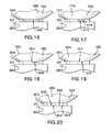
- FIG. 18shows a retro-reflective marker sphere mounting base having an alignment line on one side according to one embodiment of the present invention.
- FIG. 19shows a retro-reflective marker sphere mounting base having an alignment dot on one side according to one embodiment of the present invention.
- FIG. 20shows a retro-reflective marker sphere mounting base having alignment stars on at least two sides according to one embodiment of the present invention.
- FIG. 21shows a blister strip of packaged retro-reflective marker spheres according to one embodiment of the present invention.
- FIG. 22is a cross-sectional view of a packaged retro-reflective marker sphere according to one embodiment of the present invention.
- FIG. 23is a cross-sectional view of a packaged retro-reflective marker sphere according to one embodiment of the present invention.
- FIG. 24is a bottom plan view of the packaged retro-reflective marker sphere of FIG. 23 .
- FIG. 25is a cross-sectional view of a packaged retro-reflective marker sphere according to one embodiment of the present invention.
- FIG. 26is a bottom plan view of the packaged retro-reflective marker sphere of FIG. 25 .
- FIG. 27shows a blister card of packaged retro-reflective marker spheres according to one embodiment of the present invention.
- FIG. 28is a perspective view of a retro-reflective marker sphere that may be used in various embodiments of the present invention.
- FIG. 29is an exploded view of the retro-reflective marker sphere of FIG. 28 , with divets in a core ball and interior structures in a mounting recess of the core ball of the retro-reflective marker sphere omitted for simplicity of illustration.
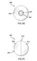
- FIG. 30is a bottom plan view of the retro-reflective marker sphere of FIG. 28 .
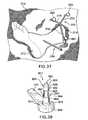
- FIG. 31is a side view of the retro-reflective marker sphere of FIG. 28 .
- FIG. 32is a perspective view of the core ball of the retro-reflective marker sphere of FIG. 28 .
- FIG. 33is a side view of the core ball of FIG. 32 .
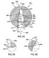
- FIG. 34is a cross-sectional view of the core ball of FIG. 32 taken along line B-B of FIG. 33 .
- FIG. 35is a close-up view of one of the two dashed-circled regions of FIG. 34 .
- FIG. 36is a close-up view of the other dashed-circled region of FIG. 34 .
- FIG. 37is a perspective view of a medical device, mounted on a human foot, on which are mounted retro-reflective marker spheres according to one embodiment of the present invention.
- FIG. 38is a perspective view of a snap-on mounting post on an arm of the medical device of FIG. 37 .
- FIG. 39is a cross-sectional view of the retro-reflective marker sphere of FIG. 1 mounted on the snap-on mounting post of FIG. 38 .
- FIG. 40is a cross-sectional view of a packaged retro-reflective marker sphere according to one embodiment of the present invention.
- FIG. 41is a cross-sectional view of a packaged retro-reflective marker sphere according to one embodiment of the present invention.
- FIG. 42is a bottom plan view of the packaged retro-reflective marker sphere of FIG. 41 .
- FIG. 43is a cross-sectional view of the core ball of FIG. 32 taken along line B-B of FIG. 33 according to an alternate embodiment.
- FIG. 44is a cross-sectional view of a packaged retro-reflective marker sphere according to one embodiment of the present invention.
- FIG. 45is a cross-sectional view of a packaged retro-reflective marker sphere according to one embodiment of the present invention.
- directional termssuch as “top,” “bottom,” “upper,” “lower,” “above,” “below,” “left,” “right,” “horizontal,” “vertical,” “up,” “down,” etc., are used merely for convenience in describing the various embodiments of the present invention.
- the embodiments of the present inventionmay be oriented in various ways.
- the diagrams, apparatuses, etc., shown in the drawing figuresmay be flipped over, rotated by 90° in any direction, reversed, etc.
- alignment indicatorrefers to a symbol or other type of indicator on one or more sides of a mounting base of a retro-reflective marker sphere that may be used to determine if the retro-reflective marker sphere is aligned properly on its mounting post.
- alignment indicatorsinclude: lines, dots, letters, numbers, stars, shapes, etc.
- audiblerefers to a sound that may be heard by an human being having normal hearing.
- the term “backing layer”refer to the one or more layers of a blister pack joined to the pocket layer to thereby contain an item in the blister pack. If the backing layer has an opening, part of the item contained in the blister pack may protrude through the opening.
- Suitable materials for use as a backing layerinclude paper, cardboard, plastic, metal foil, such as aluminum foil, mylar, Tyvek® (flashspun high-density polyethylene fiber material manufactured by Dupont), etc.
- one backing layermay be made of cardboard, a stiff plastic, etc., to provide structural stability to the blister pack, and a second backing layer may be made of a metal foil that is rupturable.
- blister cardrefers to a blister package comprising a connected two-dimensional set of blister packs.
- blister packrefers to the common meaning of the term “blister pack,” i.e., a package comprising a pocket formed of a formable material such as a plastic and one or more backing layers that seal the package.
- formable materialsinclude thermoformable or thermosettable plastics.
- blister packagerefers to a package comprising one or more blister packs.
- blister striprefers to a blister package comprising a one-dimensional strip of blister packs.
- chrome-coloredrefers to a bright silver mirrored reflective finish.
- chrome-colored retro-reflective coveringsinclude tapes, inks, emergency reflective sign paints, emergency reflective road markings, etc.
- centipoiserefers to a unit of dynamic viscosity and is the amount of force necessary to move a layer of liquid in relation to another liquid. Centipoise is considered the standard unit of measurement for fluids of all types. It is one hundredth of a poise. Water at approximately 70° F. (21° C.) is about one centipoise. When determining centipoise, all other fluids are calibrated to the viscosity of water. Blood has a viscosity of 10 centipoise, and ethylene glycol has a viscosity of 15 centipoise.
- engagerefers to a contacting and/or interlocking interaction between two or more engagement structures.
- engagement structurerefers to a structure on a first object, such as a retro-reflective marker sphere or a post, that is shaped to engage one or more engagement structures on a second object, such as a post or a retro-reflective marker sphere.
- engagement structuresinclude interior screw threads, exterior screw threads, ledges, tabs, recesses, rims, etc.
- exterior snap-on engagement structurerefers to an engagement structure on an exterior surface of an object, such as a mounting post.
- exterior snap-on engagement structuresinclude the exterior screw thread in FIG. 12 ; the recess in the mounting post shown in FIGS. 38 and 39 ; etc.
- the term “generally hemispherical”refers to an object, such as a retro-reflective marker sphere upper or lower retro-reflective covering, that is at least 50% hemispherical in shape over its surface.
- An object that is generally hemispherical in shapemay include one or more openings and/or recesses.
- An object that is generally hemispherical in shape, such as a retro-reflective marker sphere upper or lower retro-reflective coveringmay be comprised of one piece or two or more pieces.
- An object that is generally hemispherical in shapemay be hollow or solid.
- the term “generally spherical”refers to an object, such as a retro-reflective marker sphere covering or a core ball, that is at least 50% spherical in shape over its surface.
- An object that is generally spherical in shapemay include one or more openings and/or recesses.
- An object that is generally spherical in shape, such as a retro-reflective marker sphere coveringmay be comprised of one piece or two or more pieces.
- An object that is generally spherical in shapemay be hollow or solid.
- gold-coloredrefers to a bright gold reflective finish.
- examples of gold-colored retro-reflective coveringsinclude tapes, inks, paints for cars, bikes and motorcycles, decorative markings for cars, bikes and motorcycles, etc.
- interior snap-on engagement structurerefers to an engagement structure on an interior surface or recess of an object, such as a retro-reflective marker sphere.
- Examples of interior snap-on engagement structuresinclude the semi-locking interior screw thread shown in FIGS. 10 , 11 and 12 ; the raised rim shown in FIGS. 34 and 39 ; etc.
- the term “manually removable”refers to a pocket layer joined to a backing layer by an adhesive that has a peel strength of no greater than 5 lbs. (22.24 N) of force.
- a manually removable adhesivemay have a peel strength of no greater than 3 lbs. (13.34 N) of force.
- MRImagnetic resonance imaging
- NMRInuclear magnetic resonance imaging
- MRTmagnetic resonance tomography
- MRIprovides good contrast between the different soft tissues of the body, which makes it especially useful in imaging the brain, muscles, the heart, and cancers compared with other medical imaging techniques such as computed tomography (CT) or X-rays. Unlike CT scans or traditional X-rays, MRI does not use ionizing radiation.
- CTcomputed tomography
- X-raysX-rays
- non-rupturable materialrefers to a material used as a backing layer for a blister pack that is not designed to be manually ruptured by a user.
- pocket layerrefers to the layer of a blister pack including a pocket or bubble.
- materials that may be used in pocket layersincludes transparent or translucent plastics such as clear or colored polyvinyl chloride (PVC), rigid PVC, duplex structures such as PVC/PCTFE (polyvinyl chloride/polychlorotrifluoroethylene), triplex laminates such as PVC/PE/PCTFE (polyvinyl chloride/polyethylene/polychlorotrifluoroethylene), etc.
- polygonwithout any modifier refers to both regular and irregular polygons.
- an object that is “polygonal” in shapemay be in the shape of a regular or an irregular polygon.
- a polygon or an object that is polygonal in shapemay have rounded corners.
- proximalrefers to the direction toward the end of a retro-reflective marker sphere where a mounting base of the retro-reflective marker sphere is located, toward the base of a mounting post or toward the end of a medical device that is held by a user or that is used to mount the medical device in place.
- distalrefers to the direction opposite the “proximal” direction.
- radiopaquerefers to an object, such as a retro-reflective marker sphere or a core ball, that blocks x-rays or other types of electromagnetic radiation such as UV (ultraviolet) light.
- a non-radiopaque materialsuch as a plastic, may be made radiopaque by adding a radiopaque dopant, such as barium, to the material.
- radiopaque materialsthat may be used as dopants to make radiopaque core balls and radiopaque retro-reflective marker spheres of the present invention include calcium phosphate cement, radiopaque polymer salts, iodine agents such as barium sulfate, metal agents such as tantalum, etc.
- retro-reflectiverefers to the conventional meaning of the term “retro-reflective,” i.e., an object or surface that reflects light back to its source with a minimum scattering of light.
- Retro-reflective materialssuch as retro-reflective tape and paint may be made in a variety of colors.
- retro-reflective tapes and materialsare commonly used in pavement marking tapes, transport trailer tapes, and safety markers or cones in colors such as white, yellow, red and orange.
- the term “retro-reflective marker sphere”refers to a retro-reflective marker sphere that is retro-reflective and/or has a retro-reflective covering on at least part of the retro-reflective marker sphere. In some embodiments of the present invention, the retro-reflective covering covers at least 95% of the retro-reflective marker sphere.
- the term “right-side-up orientation”refers to a retro-reflective marker sphere oriented in a blister pack so that the proximal end of the retro-reflective marker sphere is adjacent to the backing layer of the blister pack.
- the term “rupturable material”refers to a material used as a backing layer for a blister pack that may be ruptured by a user pushing out a retro-reflective marker sphere enclosed in the blister pack through the backing layer, thereby allowing the retro-reflective marker sphere to be removed from the blister pack.
- rupturable materialsinclude paper, cardboard, metal foils such as aluminum, some types of plastics, etc.
- the term “semi-locking screw thread”refers to a first screw thread which includes a thread that has a ridge that does not fully mate with the groove of a second screw thread that engages the first screw thread.
- single-piecerefers to an object that is made of a single piece, as opposed to being made of two or more pieces.
- the term “snap-on mounting post”refers to a mounting post that is designed to allow a snap-on retro-reflective marker sphere to be snapped onto the mounting post.
- the term “snap-on retro-reflective marker sphere”refers to a retro-reflective marker sphere that snaps onto a mounting post of a medical device.
- the mounting postmay be either a snap-on mounting post or a threaded mounting post.
- the present inventionprovides a retro-reflective marker sphere that is designed to be snapped onto a threaded mounting post.
- threaded mounting postrefers to a mounting post that includes one or more exterior screw threads that is designed to allow a retro-reflective marker sphere with a threaded mounting recess to be screwed onto the mounting post.
- the term “threaded retro-reflective marker sphere”refers to a retro-reflective marker sphere that includes one or more interior screw threads in a mounting recess of the retro-reflective marker sphere.
- two-piece retro-reflective coveringrefers to a retro-reflective covering that comprises only two pieces. Examples of two-piece retro-reflective coverings are shown in FIGS. 1 , 2 , 3 , 4 , 5 , 6 , 10 , 28 , 29 , 30 , 31 , 32 , 33 , 34 , 35 and 36 .
- viscosityrefers to the measure of a fluid's resistance to flow and may be thought of as fluid friction. Thinner liquids, such as water, have lower viscosities, while thicker liquids like oil have higher viscosities.
- white-coloredrefers to a white finish that reflects light back towards the source of the light.
- white-colored retro-reflective coveringsinclude pavement marking tapes, transport trailer tapes, and safety markers or cones.
- Retro-reflective marker spheresalso referred to as passive reflective markers, are widely used in image guidance systems.
- retro-reflective marker sphereshave been used in military, entertainment, sports, and medical applications, and for validation of computer vision and robotics.
- retro-reflective marker sphereshave been used in recording actions of human actors and using that information to animate digital character models in 2D or 3D computer animation.
- motion-capture sessionsmovements of one or more actors are sampled many times per second, although with most techniques (recent developments from Weta Digital use images for 2D motion capture and project into 3D), motion capture records only the movements of the actor, not his or her visual appearance.
- This animation datais mapped to a 3D model so that the model performs the same actions as the actor.
- Thisis comparable to the older technique of rotoscope, such as that used in Ralph Bakshi's The Lord of the Rings (1978) and American Pop (1981) animated films in which the motion of an actor was filmed, and then the film was used as a guide for the frame-by-frame motion of a hand-drawn animated character.
- Camera movementsmay also be motion captured so that a virtual camera in the scene will pan, tilt, or dolly around the stage driven by a camera operator while the actor is performing, and the motion capture system can capture the camera and props as well as the actor's performance.
- Thisallows the computer-generated characters, images and sets to have the same perspective as the video images from the camera.
- a computerprocesses the data and displays the movements of the actor, providing the desired camera positions in terms of objects in the set. Retroactively obtaining camera movement data from the captured footage is known as match moving or camera tracking.
- one-time-use retro-reflective markers spheresare used to aid registration and instrument tracking during image guided surgery procedures such as neurological procedures, spin procedure and orthopedic procedures.
- retro-reflective marker sphereshave a high coefficient of retro-reflection on the external surface to provide feedback to the system/camera. These surfaces consist of micro glass spheres that reflect light.
- the spheresmay need to be sterilized using processes such as ethylene oxide (ETO) gas sterilization, gamma-ray sterilization and electron beam (E-beam) sterilization. These sterilization processes may negatively impact polymers and may degrade the polymer structure. For this reason, for medical applications, retro-reflective marker spheres may need to be made of materials that are able to withstand the impact of sterilization.
- ETOethylene oxide
- E-beamelectron beam
- retro-reflective marker spheresmay be mounted on various types of surgical tooling that may be used. For example, from two to five retro-reflective marker spheres may mounted on a surgical probe. Depending on the type of posts used on a particular surgical probe, each of the retro-reflective marker spheres is mounted on a surgical probes either by screwing the retro-reflective marker sphere onto a threaded mounting post of the surgical probe or by snapping the retro-reflective marker sphere onto a snap-on post of the surgical probe. Once mounted on a surgical problem, retro-reflective marker spheres provide an accuracy reference point for the surgical probe in three-dimensional space.
- the present inventionprovides a threaded sterile retro-reflective marker sphere that includes a mounting base for improved mounting on a threaded mounting post of a medical device used in image-guided surgical procedures.
- the retro-reflective marker spherecomprises an interior ball on which are mounted two retro-reflective hemispheres to form a spherical covering.
- a retro-reflective marker sphereincludes a threaded mounting recess in the interior ball at one end into which a threaded mounting post of the medical device extends when the retro-reflective marker sphere is mounted on the medical device.
- the lower sphereincludes an opening aligned with a mounting recess in the interior core ball.
- the interior screw thread in the mounting recess of a retro-reflective marker sphereis used to determine the point at which the retro-reflective marker sphere is fully mounted on a threaded mounting post.
- the retro-reflective marker sphereis considered fully mounted when the retro-reflective marker sphere can be turned no more on a threaded mounting post of a medical device.
- the mounting recess of a conventional retro-reflective marker sphereincludes a thread along the entire length of the mounting recess.
- the interior core ballincludes a mounting base that extends beyond the edge of the bottom hemisphere so that the mounting base is the only part of the retro-reflective maker sphere that contacts the base of the threaded mounting post.
- a retro-reflective marker spherein one embodiment, includes a mounting recess having an interior screw thread to allow the retro-reflective marker sphere to be mounted on threaded mounting post, but the interior screw thread does not extend all the way to the top of the mounting recess.
- a non-threaded portion of the mounting recessis used for alignment of the retro-reflective marker sphere in the axial direction of the threaded mounting post.
- FIGS. 1 , 2 , 3 and 4show a retro-reflective marker sphere 102 according to one embodiment of the present invention.
- Retro-reflective marker sphere 102comprises a core ball 112 on which is mounted an upper retro-reflective covering piece 114 and a lower retro-reflective covering piece 116 .
- Upper retro-reflective covering piece 114 and lower retro-reflective covering piece 116are generally hemispherical in shape. Where upper retro-reflective covering piece 114 and lower retro-reflective covering piece 116 meet there is a seam 118 .
- Lower retro-reflective covering piece 116includes a circular opening 120 .
- Core ball 112shown in detail in FIGS.
- Mounting recess 134is circular in cross-section and has a circular opening 144 centered in mounting base 136 .
- Mounting base 136is octagonal in shape, i.e., mounting base 136 has eight sides 146 and eight corners 148 .
- mounting base 136extends through circular opening 120 of lower retro-reflective covering piece 116 so that a lower surface 152 of mounting base 136 is spaced proximally from a lower edge 154 of circular opening 120 and lower retro-reflective covering piece 116 .
- Mounting recess 134includes a recess lower portion 156 having a cylindrical wall 158 , a recess upper portion 160 having a cylindrical wall 162 and a rounded upper end 164 .
- Recess lower portion 156includes an interior screw thread 166 on cylindrical wall 158 .
- Recess lower portion 156is larger in diameter than recess upper portion 160 .
- Recess upper portion 160does not have an interior screw thread.
- Recess lower portion 156 and recess upper portion 160each have a circular cross-section.
- upper retro-reflective covering piece 114covers an upper half 172 of core ball 112
- lower retro-reflective covering piece 116covers a lower half 174 of core ball 112 .
- a circular ledge 182is formed at an upper end 184 of recess lower portion 156 due to the fact that recess lower portion 156 is larger in diameter than recess upper portion 160 .
- Retro-reflective marker sphere 102 and core ball 112have an axis shown by double-headed dashed arrow 190 , shown in FIGS. 1 and 4 , that extends through the center of mounting recess 134 .
- upper retro-reflective covering piece 114 and lower retro-reflective covering piece 116form a retro-reflective covering 192 that is generally spherical in shape.
- FIG. 7shows a medical device 702 on which are mounted three retro-reflective marker spheres 102 .
- Medical device 702is mounted by a mounting device 706 on a human foot 712 extending through an opening 714 in a covering blanket 716 .
- Medical device 702includes three arms 722 , 724 and 726 .
- the three retro-reflective marker spheresprovide a precise location in three-dimensional space of the contact area between the probe and the foot of the patient.
- the position of each of the retro-reflective marker spheresis registered using the vision system which extrapolates the position of probe relative to the foot of the patient.
- FIG. 8shows a mounting post 812 that is mounted on an upper surface 814 of a circular end 816 of arm 722 of medical device 702 .
- Mounting post 812includes a post base 818 , a cylindrical post lower portion 820 , a post neck portion 822 , a post middle portion 824 , a cylindrical post upper portion 826 and a post rounded end 828 .
- Post middle portion 824includes an exterior screw thread 832 .
- Post lower portion 820includes an upper surface 842 .
- FIG. 9shows retro-reflective marker sphere 102 mounted on mounting post 812 .
- Interior screw thread 166 of retro-reflective marker sphere 102screws onto exterior screw thread 832 .
- Lower surface 152 of mounting base 136abuts upper surface 842 of post lower portion 820 , thereby ensuring that retro-reflective marker sphere 102 is mounted properly on mounting post 812 .
- Post upper portion 826 and post rounded end 828are received by recess upper portion 160 and rounded upper end 164 , respectively, of mounting recess 134 of retro-reflective marker sphere 102 to help maintain the alignment of retro-reflective marker sphere 102 on mounting post 812 in the direction shown by double-headed arrow 912 , i.e., the axial direction for mounting post 812 .
- a gap 922is formed between a top 924 of exterior screw thread 832 and ledge 182 due to lower surface 152 of mounting base 136 abutting upper surface 842 of post lower portion 820 prior to exterior screw thread 832 travelling fully upward in interior screw thread 166 .
- FIG. 10shows a retro-reflective marker sphere 1002 according to one embodiment of the present invention that may be snapped onto mounting post 812 as shown in FIGS. 11 and 12 .
- Retro-reflective marker sphere 1002comprises a core ball 1012 on which is mounted an upper retro-reflective covering piece 1014 and a lower retro-reflective covering piece 1016 .
- Upper retro-reflective covering piece 1014 and lower retro-reflective covering piece 1016are generally hemispherical in shape. Where upper retro-reflective covering piece 1014 and lower retro-reflective covering piece 1016 meet there is a seam 1018 .
- Lower retro-reflective covering piece 1016includes a circular opening 1020 .
- Core ball 1012has a generally spherical body portion 1032 , a mounting recess 1034 , a mounting base 1036 , an upper central circular (dimple) divet 1038 and eight upper peripheral circular (dimples) divets 1040 .
- Mounting recess 1034is circular in cross-section and has a circular opening 1044 centered in mounting base 1036 .
- Mounting base 1036is octagonal in shape, i.e., mounting base 1036 has eight sides 1046 and eight corners (not shown).
- Mounting base 1036extends through circular opening 1020 of lower retro-reflective covering piece 1016 so that a lower surface 1052 of mounting base 1036 is spaced proximally from a lower edge 1054 of circular opening 1020 and lower retro-reflective covering piece 1016 .
- Mounting recess 1034includes a recess lower portion 1056 having a cylindrical wall 1058 , a recess upper portion 1060 having a cylindrical wall 1062 and a rounded upper end 1064 .
- Recess lower portion 1056includes a semi-locking interior screw thread 1066 at an upper end 1068 of recess lower portion 1056 .
- Semi-locking interior screw thread 1066is “semi-locking” because semi-locking interior screw thread 1066 has a rounded ridge 1070 that does not fully mate with groove 1072 of exterior screw thread 832 of mounting post 812 , as shown in FIG. 12 .
- the interaction of semi-locking interior screw thread 1066 and exterior screw thread 832 of mounting post 812shown in detail in FIG. 12 corresponding to dashed-circled region 1074 of FIG. 11 , causes an audible “snap” when retro-reflective marker sphere 1002 is snapped onto mounting post 812 .
- a lower section 1080 of recess lower portion 1056does not include a screw thread to allow retro-reflective marker sphere 1002 to be snapped onto mounting post 812 .
- Recess lower portion 1056is larger in diameter than recess upper portion 1060 .
- Recess upper portion 1060does not have an interior screw thread.
- Recess lower portion 1056 and recess upper portion 1060each have a circular cross-section.
- upper retro-reflective covering piece 1014covers an upper half 1082 of core ball 1012
- lower retro-reflective covering piece 1016covers a lower half 1084 of core ball 1012 .
- Retro-reflective marker sphere 1002 and core ball 1012have an axis shown by double-headed dashed arrow 1090 in FIG. 10 that extends through the center of mounting recess 1034 .
- upper retro-reflective covering piece 1014 and lower retro-reflective covering piece 1016form a retro-reflective covering 1092 that is generally spherical in
- the mounting baseis octagonal in shape, i.e., the mounting base has an octagonal-shaped cross-section in a plane perpendicular to the axis of the retro-reflective marker sphere and the core ball
- the mounting basemay have various shapes such as circular, oval, triangular, star-shaped, square, rectangular, pentagonal, hexagonal, etc.
- the mounting basemay be a shape such as a square, rectangle, pentagon, hexagon, octagon, etc., which has corners that allow for more precise molding of the core ball.
- the corners/edgesprevent the core ball from turning in an injection mold.
- the corners/edgesalso prevent counter-rotation of the core ball during unscrewing of a core pin used in forming the threaded mounting recess during injection molding.
- the sides of the mounting baseare straight, in other embodiments the sides of the mounting base may be curved in either a convex or concave fashion. Also, even when the sides of mounting base are curved, the sides may still meet at corners.
- the corners of the mounting basemay be formed by one or more rectangular spokes or by triangular points that radiate from one or more sides of a mounting base that is otherwise polygonal, circular or oval in shape.
- the rectangular spokesmay radiate from the mounting base like the four arms of a plus sign, the six arms of an asterisk, etc.
- the triangular pointsmay radiate from the sides of the mounting base like the points of a four, five, six, seven, eight, etc. pointed star.
- FIG. 13shows a retro-reflective marker sphere 1302 according to one embodiment of the present invention which includes mounting base 1312 that is triangular in shape, i.e., mounting base 1312 has three sides 1314 and three corners 1316 .
- mounting base 1312In the center of mounting base 1312 is a mounting recess 1322 that is similar to mounting recess 134 .
- FIG. 14shows a retro-reflective marker sphere 1402 according to one embodiment of the present invention which includes mounting base 1412 that is square in shape.
- Mounting base 1412has four sides 1414 and four corners 1416 .
- In the center of mounting base 1412is a mounting recess 1422 that is similar to mounting recess 134 .
- FIG. 13shows a retro-reflective marker sphere 1302 according to one embodiment of the present invention which includes mounting base 1312 that is triangular in shape, i.e., mounting base 1312 has three sides 1314 and three corners 1316 .
- mounting recess 1322In
- FIG. 15shows a retro-reflective marker sphere 1502 according to one embodiment of the present invention which includes mounting base 1512 that is hexagonal in shape.
- Mounting base 1512has six sides 1514 and six corners 1516 .
- In the center of mounting base 1512is a mounting recess 1522 that is similar to mounting recess 134 .
- retro-reflective marker spheres 1302 , 1402 and 1502are identical to retro-reflective marker sphere 102 .
- the mounting base of the retro-reflective marker spheremay include one or more alignment indicators.
- FIGS. 16 , 17 , 18 , 19 and 20show examples of some of the types of alignment indicators that may be used to determine if a retro-reflective marker sphere is aligned properly on a mounting post.
- FIG. 16shows a retro-reflective marker sphere 1602 according to one embodiment of the present invention having an octagonal-shaped mounting base 1612 that has a bright contrasting color shown by a pattern 1614 in comparison with a retro-reflective covering 1616 of retro-reflective marker sphere 1602 that may be easily seen by a user.
- the bright contrasting colorfunctions as an alignment indicator, allowing the proper alignment of retro-reflective marker sphere 1602 on post lower portion 820 of mounting post 812 to be confirmed by the person mounting retro-reflective marker sphere 1602 on mounting post 812 .
- FIG. 17shows a retro-reflective marker sphere 1702 according to one embodiment of the present invention having an octagonal-shaped mounting base 1712 with a side 1714 that has a bright contrasting color, shown by a pattern 1716 , in comparison with a retro-reflective covering 1718 of retro-reflective marker sphere 1702 and thus functions as an alignment indicator.
- the bright contrasting colorallows the proper alignment of retro-reflective marker sphere 1702 on post lower portion 820 of mounting post 812 to be confirmed by the person mounting retro-reflective marker sphere 1702 on mounting post 812 .
- the “bright contrasting color”is a variation in the substance with respect to light reflected by one or more sides of the mounting base.
- the contrasting colormay be observed visually and/or by measurement of hue, saturation and brightness of the reflected light from the one or more sides of the mounting base.
- FIG. 18shows a retro-reflective marker sphere 1802 according to one embodiment of the present invention having an octagonal-shaped mounting base 1812 with a side 1814 having an alignment line 1816 that has a bright contrasting color in comparison with a retro-reflective covering 1818 of retro-reflective marker sphere 1802 and thus functions as an alignment indicator.
- the bright contrasting colorallows the proper alignment of retro-reflective marker sphere 1802 on post lower portion 820 of mounting post 812 to be confirmed by the person mounting retro-reflective marker sphere 1802 on mounting post 812 .
- FIG. 19shows a retro-reflective marker sphere 1902 according to one embodiment of the present invention having an octagonal-shaped mounting base 1912 with a side 1914 having an alignment dot 1916 that has a bright contrasting color in comparison with a retro-reflective covering 1918 of retro-reflective marker sphere 1902 and thus functions as an alignment indicator.
- the bright contrasting colorallows the proper alignment of retro-reflective marker sphere 1902 on post lower portion 820 of mounting post 812 to be confirmed by the person mounting retro-reflective marker sphere 1902 on mounting post 812 .
- FIG. 20shows a retro-reflective marker sphere 2002 according to one embodiment of the present invention having an octagonal-shaped mounting base 2012 with sides 2014 and 2016 having respective alignment stars 2018 and 2020 that each have a bright contrasting color in comparison with a retro-reflective covering 2032 of retro-reflective marker sphere 2002 and thus function as alignment indicators.
- the bright contrasting colorallows the proper alignment of retro-reflective marker sphere 2002 on post lower portion 820 of mounting post 812 to be confirmed by the person mounting retro-reflective marker sphere 2002 on mounting post 812 .
- FIG. 21shows a blister strip 2102 comprising ten blister packs 2112 according to one embodiment of the present invention.
- Blister strip 2102includes a transparent or translucent pocket layer 2122 and a backing layer 2124 joined to pocket layer 2122 .
- Pocket layer 2122includes dome-shaped pockets 2132 and flat portions 2134 . The presence of pockets 2132 forms openings 2136 that are each slightly larger in diameter than each retro-reflective marker sphere 102 .
- Each blister pack 2112is separated from one or two adjacent blister packs 2112 by a perforation 2142 that extends at least through pocket layer 2122 and may extend through backing layer 2124 .
- Perforation 2142allows neighboring blister packs 2112 to be separated from each other by a user tearing pocket layer 2122 and backing layer 2124 along a perforation 2142 between neighboring blister packs 2112 .
- FIG. 22shows a cross-section of one retro-reflective marker sphere 102 in a blister pack 2112 .
- FIG. 21shows a blister strip used with one particular type of retro-reflective marker sphere
- the blister strips of the present inventionmay be used with various types of retro-reflective marker spheres, including retro-reflective marker spheres for both threaded and snap-on mounting posts.
- FIGS. 23 and 24show a retro-reflective marker sphere 102 in a blister pack 2302 according to one embodiment of the present invention comprising a transparent or translucent pocket layer 2312 and a backing layer 2314 joined to pocket layer 2312 .
- Backing layer 2314includes an octagonal-shaped recessed portion 2316 .
- Pocket layer 2312includes a dome-shaped pocket 2322 .
- Mounting base 136fits into octagonal-shaped recessed portion 2316 to thereby help keep retro-reflective marker sphere 102 in a right-side-up orientation in blister pack 2302 .
- Pocket 2322contains retro-reflective marker sphere 102 .
- a series of blister packs 2302may be part of a blister strip similar to blister strip 2102 .
- the recess shown in FIGS. 23 and 24is octagonal-shaped, the recess in the backing layer of the present invention may have various shapes including circular, oval, lozenge-shaped, etc., as well as various polygonal shapes.
- FIGS. 25 and 26show a retro-reflective marker sphere 102 in a blister pack 2502 according to one embodiment of the present invention comprising a transparent or translucent pocket layer 2512 and a backing layer 2514 joined to pocket layer 2512 .
- Backing layer 2514includes a circular-shaped opening 2516 .
- Mounting base 136extends through circular-shaped opening 2516 to thereby help keep retro-reflective marker sphere 102 in right-side-up orientation in blister pack 2502 .
- FIG. 25shows a protective layer 2522 that is joined to backing layer 2514 to protect mounting base 136 .
- Protective layer 2522is joined to backing layer 2514 using an adhesive 2524 .
- Adhesive 2524may not be present in the region beneath mounting base 136 to avoid adhesive 2524 possibly sticking to mounting base 136 .
- Adhesive 2524 on protective layer 2522is sufficiently weak to allow protective layer 2522 to be removed from backing layer 2514 .
- retro-reflective marker sphere 102may be screwed onto a mounting post, such as mounting post 812 (not shown in FIGS. 25 and 26 ), while still in blister pack 2502 . Retro-reflective marker sphere 102 may then be removed from blister pack 2502 .
- Pocket layer 2512includes a dome-shaped pocket 2532 that contains retro-reflective marker sphere 102 .
- a series of blister packs 2502may be part of a blister strip similar to blister strip 2102 .
- a usermay screw retro-reflective marker sphere 102 onto a mounting post by grasping retro-reflective marker sphere 102 through pocket 2532 and turning retro-reflective marker sphere 102 on the thread of the mounting post.
- the opening in the backing layer in FIGS. 25 and 26is circular, the opening could be octagonal in shape, to match the shape of the mounting base of the retro-reflective marker sphere, or any other shape, such as oval, lozenge-shaped, etc.
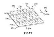
- FIG. 27shows a 4 ⁇ 4 blister card 2702 comprising sixteen blister packs 2712 according to one embodiment of the present invention.
- Blister card 2702includes a transparent or translucent pocket layer 2722 and a backing layer 2724 joined to pocket layer 2722 .
- Pocket layer 2722includes dome-shaped pockets 2732 and flat portions 2734 . The presence of pockets 2732 forms openings 2736 that are each slightly larger in diameter than each retro-reflective marker sphere 102 .
- Each blister pack 2712is separated from two, three or four adjacent blister packs 2712 by perforations 2742 and 2744 that extend at least through pocket layer 2722 and may extend through backing layer 2724 .
- Perforations 2742 and 2744allow neighboring blister packs 2712 to be separated from each other by a user tearing pocket layer 2722 and backing layer 2724 along perforation 2742 .
- Perforations 2742 and 2744are oriented in respective perpendicular directions shown by double-headed arrows 2752 and 2754 , respectively.
- a blister strip or blister cardmay be produced by vacuum-forming or thermo-forming the “pockets.” Compression plates or rollers may be used to apply the backing heaters that adhere the backing substrates to the pocket layer.
- FIG. 27shows a blister card used with one particular type of retro-reflective marker sphere
- the blister cards of the present inventionmay be used with various types of retro-reflective marker spheres, including retro-reflective marker spheres for both threaded and snap-on posts.
- blister packs similar to blister packs 2302 and 2502may be arranged in a two-dimensional blister card similar to blister card 2702 .
- a blister card of the present inventionmay have any number of blister packs in any two-dimensional arrangement.
- the pocket layer of each blister packis made of a transparent or translucent plastic
- the backing layermay be made of materials such as plastic, paper, cloth, metal foil, a combination of materials, etc., to which the pocket layer is adhered using an adhesive that allows the pocket layer to be removed from the backing layer, thereby allowing a retro-reflective marker sphere to be removed from the blister pack by a user.
- the pocket layer of each blister packis made of a transparent or translucent plastic
- the backing layeris made of a rupturable material, such as metal foil, similar to the blister packs used with pills and tablets.
- the backing layermay be joined to the pocket layer using an adhesive, by thermoforming the backing layer to the pocket layer, or by any other process for joining the backing layer of a blister pack to the pocket layer of a blister pack.
- Such a configurationallows a retro-reflective marker sphere to be removed from a blister pack by pressing down on the dome-shaped pocket of the blister pack, thereby forcing the retro-reflective marker sphere through the opening in the pocket layer and rupturing the rupturable material of the backing layer.
- the blister packs shown in the drawingsare shown as being used with a particular retro-reflective marker sphere of the present invention
- the blister packs of the present inventionmay be used with various types of retro-reflective marker spheres, such as the snap-on retro-reflective spheres shown in FIGS. 10 , 28 , 29 , 30 , 31 , 32 , 33 , 34 , 35 and 36 , as well as with other types of retro-reflective marker spheres.
- FIGS. 28 , 29 , 30 and 31show a retro-reflective marker sphere 2802 according to one embodiment of the present invention.
- Retro-reflective marker sphere 2802is a snap-on retro-reflective marker sphere that is designed to snap onto a snap-on mounting post of a medical device (not shown in FIGS. 28 , 29 , 30 and 31 ).
- Retro-reflective marker sphere 2802comprises a core ball 2812 on which is mounted an upper retro-reflective covering piece 2814 and a lower retro-reflective covering piece 2816 .
- Upper retro-reflective covering piece 2814 and lower retro-reflective covering piece 2816are generally hemispherical in shape.
- Lower retro-reflective covering piece 2816includes a circular opening 2820 .
- Core ball 2812shown in detail in FIGS. 32 , 33 , 34 , 35 and 36 , has a generally spherical body portion 2832 , a mounting recess 2834 , an upper central circular (dimple) divet 2838 and sixteen upper peripheral circular (dimples) divets 2840 .
- Mounting recess 2834is circular in cross-section and has a circular opening 2844 .
- upper retro-reflective covering piece 2814covers an upper half 2872 of core ball 2812
- lower retro-reflective covering piece 2816covers a lower half 2874 of core ball 2812
- Retro-reflective marker sphere 2802 and core ball 2812have an axis shown by double-headed dashed arrow 2890 , shown in FIG. 28 , that extends through the center of mounting recess 2834 .
- upper retro-reflective covering piece 2814 and lower retro-reflective covering piece 2816form a retro-reflective covering 2892 that is generally spherical in shape.
- FIGS. 32 , 33 , 34 , 35 and 36show core ball 2812 and details of mounting recess 2834 .
- Mounting recess 2834includes a flared recess base portion 3412 , a cylindrical recess lower portion 3414 , a cylindrical recess waist portion 3416 , a recess chamfered portion 3418 , a cylindrical recess middle portion 3420 , a recess frustoconical portion 3422 , a cylindrical recess upper portion 3424 and a recess top 3426 . Because recess waist portion 3416 is smaller in diameter than recess lower portion 3414 , a ledge 3432 is formed at an upper end 3434 of recess lower portion 3414 .
- Recess waist portion 3416has a cylindrical wall 3436 . Details of dashed-circled regions 3442 and 3444 are shown in FIGS. 35 and 36 , respectively. Although as shown in FIG. 35 the angle of an angled wall 3452 of recess base portion 3412 with respect to a line 3454 parallel to the axis of core ball 2812 is 45°, this angle may vary depending on the particular mounting post on which retro-reflective marker sphere 2802 is to be mounted. Similarly, although as shown in FIG.
- the angle of an angled wall 3462 of recess frustoconical portion 3422 with respect to a line 3464 parallel to the axis of core ball 2812is 30°, this angle may vary depending on the particular mounting post on which retro-reflective marker sphere 2802 is to be mounted.
- ledge 3432 , cylindrical wall 3436 and angled wall 3452define a raised rim 3472 that projects into mounting recess 2834 .
- FIG. 37shows a medical device 3702 on which are mounted three retro-reflective marker spheres 2802 .
- Medical device 3702functions similarly to medical device 702 .
- Medical device 3702is mounted by a mounting device 3706 on a human foot 3712 extending through an opening 3714 in a covering blanket 3716 .
- Medical device 3702includes three arms 3722 , 3724 and 3726 .
- FIG. 38shows a snap-on mounting post 3812 that is mounted on an upper surface 3814 of a circular end 3816 of arm 3722 of medical device 3702 .
- Mounting post 3812includes a post base 3818 , a cylindrical post lower portion 3820 , a cylindrical post middle portion 3824 , a post upper chamfered portion 3826 , a cylindrical post upper portion 3828 , a post frustoconical portion 3830 and a post top 3832 .
- Post lower portion 3820includes an upper surface 3842 having a circular peripheral edge 3844 .
- post upper chamfered portion 3826 , post upper portion 3828 , post frustoconical portion 3830 and post top 3832are part of a post upper end 3852 having a post upper end surface 3854 .
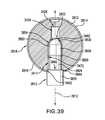
- FIG. 39shows retro-reflective marker sphere 2802 snapped onto snap-on mounting post 3812 by forcing retro-reflective marker sphere 2802 onto snap-on mounting post 3812 .
- core ball 2812is made of a resilient material
- mounting recess 2834is able to spread open slightly so that raised rim 3472 can slide along post upper end surface 3854 as retro-reflective marker sphere 2802 is forced onto snap-on mounting post 3812 .
- Raised rim 3472eventually reaches post middle portion 3824 and snaps into place beneath post upper end 3852 .
- Retro-reflective marker sphere 2802is held in place on snap-on mounting post 3812 by post upper end 3852 being trapped between recess frustoconical portion 3422 and raised rim 3472 .
- angled wall 3452 of recess base portion 3412abuts circular peripheral edge 3844 upper surface 3842 of post lower portion 3820 .
- Snap-on mounting post 3812has an axis 3912 .
- a blister pack of the present inventionmay include two or more backing layers.
- one backing layermay be made of a stiff or semi-stiff material such as cardboard or a stiff plastic that provides structural stability to the blister pack.
- the backing layer made of the stiff or semi-stiff materialmay include openings that are aligned with and in communication with openings of the pockets of the pocket layer.
- Each opening in the backing layermay have the same shape as the opening at the bottom of the respective pocket with which the opening of the backing layer is aligned.
- the openings in the backing layeralso may be roughly the same diameter as the openings of the pockets or may be larger than the openings of the pockets.
- the two backing layersmay be joined to each other by various means, such as an adhesive, and the backing layer made of the stiffer material is in turn joined to the pocket layer.
- FIG. 40shows an example of a blister pack 4002 according to one embodiment of the present invention having two backing layers, i.e., upper backing layer 4004 and lower backing layer 4006 .
- Lower backing layer 4006is joined to a lower surface 4008 of upper backing layer 4004 .
- Joined to an upper surface 4010 of upper backing layer 4004is a pocket layer 4012 having a dome-shaped pocket 4014 .
- Upper backing layer 4004may be made of a stiff or semi-stiff material such as cardboard or a stiff plastic that provides structural stability to blister pack 4002 .
- Lower backing layer 4006may be made of a rupturable or a non-rupturable material.
- FIG. 40shows a retro-reflective marker sphere 4022 in blister pack 4002 .
- Retro-reflective marker sphere 4022includes a generally spherical core ball 4024 to which is adhered a generally spherical retro-reflective covering 4026 .
- Core ball 4024includes a mounting recess 4028 having an interior screw thread 4030 .
- Retro-reflective covering 4026is comprised of a generally hemispherical upper retro-reflective covering piece 4032 and a generally spherical lower retro-reflective covering piece 4034 that meet at a seam 4036 .
- Lower retro-reflective covering piece 4034includes a circular opening 4038 .
- Upper backing layer 4004includes an opening 4040 that is aligned and in communication with an opening 4042 of pocket 4014 .
- a lower edge 4044 of lower retro-reflective covering piece 4034abuts lower backing layer 4006 .
- Mounting recesshas a distal end 4062 .
- retro-reflective marker sphere 4022may be removed from blister pack 4002 by a user pressing down on pocket 4014 , to thereby forcing retro-reflective marker sphere 4022 through opening 4042 in upper backing layer 4004 and thereby rupturing the rupturable material of lower backing layer 4006 .
- pocket layer 4012may be adhered to upper surface 4010 of upper backing layer 4004 by an adhesive that allows pocket layer 4012 to be manually removed from upper backing layer 4004 to thereby open blister pack 4002 .
- a series of blister packs 4002may be part of a blister strip similar to blister strip 2102 .
- Blister packs 4002may also be part of a blister card similar to blister card 2702 .
- a rupturable layer of a two-backing layer blister packmay include a recess for a mounting base such as that shown in FIGS. 23 and 24 or an opening for a mounting base such as that shown in FIGS. 25 and 26 .
- retro-reflective marker spherepackaged in the blister pack shown in FIG. 40
- a blister pack with two backing layersmay be used with various types of retro-reflective marker spheres.
- a multiple-backing-layer blister pack of the present inventionmay have three or more backing layers.
- FIGS. 41 and 42show a retro-reflective marker sphere 102 in a blister pack 4102 according to one embodiment of the present invention comprising a transparent or translucent pocket layer 4112 and a backing layer 4114 joined to pocket layer 4112 .
- Backing layer 4114includes a octagonal-shaped opening 4116 .
- Mounting base 136extends through circular-shaped opening 4116 to thereby help keep retro-reflective marker sphere 102 in right-side-up orientation in blister pack 4102 .
- FIG. 41shows a protective layer 4122 that is joined to backing layer 4114 to protect mounting base 136 .
- Protective layer 4122is joined to backing layer 4114 using an adhesive 4124 .
- Adhesive 4124may not be present in the region beneath mounting base 136 to avoid adhesive 4124 possibly sticking to mounting base 136 .
- Adhesive 4124 on protective layer 4122is sufficiently weak to allow protective layer 4122 to be removed from backing layer 4114 .
- retro-reflective marker sphere 102may be screwed onto a mounting post, such as mounting post 812 (not shown in FIGS. 41 and 42 ), while still in blister pack 4102 . Retro-reflective marker sphere 102 may then be removed from blister pack 4102 .
- Pocket layer 4112includes a dome-shaped pocket 4132 that contains retro-reflective marker sphere 102 .
- a series of blister packs 4102may be part of a blister strip similar to blister strip 2102 .
- Octagonal-shaped opening 4116includes eight sides 4146 and eight corners 4148 .
- a usermay screw retro-reflective marker sphere 102 onto a mounting post by grasping retro-reflective marker sphere 102 through pocket 4132 and turning retro-reflective marker sphere 102 on the thread of the mounting post.
- sides 4146 and corners 4148 of octagonal-shaped opening 4116engage respective sides 146 and corners 148 of mounting base 136 to aid in turning retro-reflective marker sphere 102 .
- a usermay screw retro-reflective marker sphere 102 onto a mounting post by grasping pocket 4132 and turning pocket 4132 to cause sides 4146 and corners 4148 of octagonal-shaped opening 4116 to engage respective sides 146 and corners 148 of mounting base 136 thereby turn retro-reflective marker sphere 102 and screw retro-reflective marker sphere 102 onto the mounting post.
- the core ball of a retro-reflective marker sphere of the present inventionmay be made of an injection-moldable plastic such as a thermoplastic polyester elastomer.
- an injection-moldable plasticsuch as a thermoplastic polyester elastomer.
- Other types of materials that may be used to form the core ballinclude polyethylene, polypropylene and other thermoplastic elastomers.
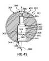
- FIG. 43shows core ball 2812 and details of mounting recess 2834 .
- Mounting recess 2834includes a flared recess base portion 3412 , a cylindrical recess lower portion 3414 , a cylindrical recess waist portion 3416 , a recess chamfered portion 3418 , a cylindrical recess middle portion 3420 , a recess frustoconical portion 3422 , a cylindrical recess upper portion 3424 and a recess top 3426 .
- recess waist portion 3416is smaller in diameter than recess lower portion 3414 , a ledge 3432 is formed at an upper end 3434 of recess lower portion 3414 .
- Recess waist portion 3416has a cylindrical wall 3436 .
- an angled wall 3452 of recess base portion 3412 with respect to a axis 2890 of core ball 2812is 45°, this angle may vary depending on the particular mounting post on which retro-reflective marker sphere 2802 is to be mounted.
- ledge 3432 , cylindrical wall 3436 and angled wall 3452define a raised rim 3472 that projects into mounting recess 2834 .
- the material 4312 of core ball 2812may comprise a filler material such as an MRI filling material.
- the MRI filling materialis capable of being registered on machine equipment utilized in an MRI exam or procedure. Utilizing MRI filling material eliminates additional manufacturing processes and materials for constructing retro-reflective surfaces on the outside of core ball 2812 .
- Disclosed embodiments of the MRI filling materialmay comprise water, watery liquids, gel or fat. In some disclosed embodiments, the viscosity ranges of the MRI filling material may range between approximately 1cP (Centipoise) or cSt (Centistokes) to 1840 cp or cSt. Material 4312 is contained within core ball 2812 .
- material 4312is encapsulated within a cavity of core ball 2812 between mounting recess 2834 and a covering layer 4314 .
- An access holemay be created in upper peripheral circular (dimple) divet 2840 , but below covering layer 4314 , to introduce material 4312 within the cavity of core ball 2812 .
- the access holemay be plugged to prevent leakage therefrom. Because the access hole is disposed in upper peripheral circular (dimple) divet 2840 and below covering layer 4314 , no interference occurs at covering layer 4314 .
- MRI filling materialsuch as water, watery liquids, gel or fat, may be injected within the cavity of core ball 2812 to provide a filler material.
- FIG. 44shows an example a retro-reflective marker sphere 102 in a blister pack 2302 according to an alternative embodiment as that illustrated and described in FIG. 23 of the present invention having two backing layers, i.e., upper backing layer 4404 and lower backing layer 4406 .
- Blister pack 2302comprises a transparent or translucent pocket layer 2312 and an upper backing layer 4404 joined to pocket layer 2312 .
- Upper backing layer 4404includes an octagonal-shaped recessed portion 2316 .
- Lower backing layer 4406includes a correspondingly shaped octagonal-shaped recessed portion 4418 sufficiently configured to accommodate octagonal-shaped recessed portion 2316 therein.
- Pocket layer 2312includes a dome-shaped pocket 2322 .
- Mounting base 136fits into octagonal-shaped recessed portion 2316 to thereby help keep retro-reflective marker sphere 102 in a right-side-up orientation in blister pack 2302 .
- Pocket 2322contains retro-reflective marker sphere 102 .
- a series of blister packs 2302may be part of a blister strip similar to blister strip 2102 .
- Lower backing layer 4406is joined to a lower surface 4408 of upper backing layer 4404 .
- Upper backing layer 4404may be made of a stiff or semi-stiff material such as cardboard or a stiff plastic that provides structural stability to blister pack 2302 .
- Lower backing layer 4406may be made of a rupturable or a non-rupturable material.
- FIG. 45shows an example of a blister pack 4002 according to an alternative embodiment as that illustrated and described in FIG. 40 of the present invention having two backing layers, i.e., upper backing layer 4004 and lower backing layer 4506 .
- Lower backing layer 4506is joined to a lower surface 4008 of upper backing layer 4004 .
- Joined to an upper surface 4010 of upper backing layer 4004is a pocket layer 4012 having a dome-shaped pocket 4014 .
- Lower backing layer 4506includes an octagonal-shaped recessed portion 4516 .
- Mounting base 136fits into octagonal-shaped recessed portion 4516 to thereby help keep retro-reflective marker sphere 4022 in a right-side-up orientation in blister pack 2302 .
- Upper backing layer 4004may be made of a stiff or semi-stiff material such as cardboard or a stiff plastic that provides structural stability to blister pack 4002 .
- Lower backing layer 4506may be made of a rupturable or a non-rupturable material.
- FIG. 45shows a retro-reflective marker sphere 4022 in blister pack 4002 .
- Retro-reflective marker sphere 4022includes a generally spherical core ball 4024 to which is adhered a generally spherical retro-reflective covering 4026 .
- Core ball 4024includes a mounting recess 4028 having an interior screw thread 4030 .
- Retro-reflective covering 4026is comprised of a generally hemispherical upper retro-reflective covering piece 4032 and a generally spherical lower retro-reflective covering piece 4034 that meet at a seam 4036 .
- Lower retro-reflective covering piece 4034includes a circular opening 4038 .
- Upper backing layer 4004includes an opening 4040 that is aligned and in communication with an opening 4042 of pocket 4014 .
- a lower edge 4044 of lower retro-reflective covering piece 4034abuts lower backing layer 4006 .
- Mounting recesshas a distal end 4062 .
- the recess in the one or more backing layers (e.g., upper back layer or lower backing layer) of the present inventionmay have various shapes including circular, oval, lozenge-shaped, etc., as well as various polygonal shapes.
- recess 2316 of the upper backing layer 4404 depicted, for example, in FIG. 44may be sufficiently sized and proportioned to be accommodated in mating fashion within corresponding recess 4418 of lower backing layer 4406 .
- the retro-reflective covering of a retro-reflective marker spheremay be a two-piece retro-reflective covering, as shown in FIGS. 1 , 2 , 3 , 4 , 5 , 6 , 10 , 28 , 29 , 30 , 31 , 32 , 33 , 34 , 35 and 36 .
- the retro-reflective coveringmay be made as a single piece.
- the upper and lower retro-reflective coveringsmay each be formed by thermoforming a piece of retro-reflective material to the appropriate trimming of the material before and/or after thermoforming. Such thermoforming allows the thickness of the retro-reflective covering to be controlled to a constant thickness throughout the retro-reflective covering.
- the gapmay be minimized or eliminated by controlling the dimensions of the formed and cut hemispheres and designing the upper and lower retro-reflective covering pieces so that the open end of each of the upper and lower retro-reflective covering pieces butt up to each other during automated assembly.
- the upper and lower retro-reflective covering piecemay be adhered to the core ball by applying a UV-curable adhesive via syringe tip, blade, spray or brush to the core ball and then curing the bond through the upper and lowering covering pieces with a combination of light and/or UV-ray intensity and time. Similar procedures may also be employed to eliminate or reduce the gaps in retro-reflective coverings comprising three or more pieces.
- thermoforming processthat may be used to form the upper and lower retro-reflective coverings
- a starting materialis chosen that is constant in thickness.
- a vacuum formingis used that allows an entire sheet of the retro-reflective covering material to be heated, stretched and then vacuum-formed into multiple identical-shaped nests to form exact replicas of each other.
- the heating, stretching and vacuum application steps of the processmay be controlled to provide consistency from cycle to cycle (each forming multiple hemispherical coverings).
- the consistent manner in which the material is heated and stretched, and the equal application of the vacuum across the surface of each section of covering to be formedcreates a consistent thickness across the entire hemisphere of the retro-reflective covering.
- the thickness of the retro-reflective coveringmay vary by no more than 0.003′′ (0.00762 cm) throughout the retro-reflective covering.
- Suitable retro-reflective materialsinclude 3M 8350 Scotchlite reflective pressure sensitive adhesive (PSA) films (made by 3M).
- the retro-reflective coatingmay be a layer of a retro-reflective paint.
- the upper and lower retro-reflective coveringsmay be mounted on the core ball using an adhesive.
- Suitable adhesivesinclude cyanoacrylates, light-cure adhesives, UV-cure adhesives, etc.
- the adhesivemay be cured by exposing the covered core ball to UV light to adhere the upper and lower retro-reflective coverings to the core ball.
- the core ballhas eight smaller circular peripheral divets surrounding one larger central circular divet
- the core ballmay have various numbers, sizes and shapes of divets, and the divets may be arranged in various patterns.
- One purpose of the central divetis to provide a recess at the location of the gate for the injection mold cavity for the core ball.
- the number and/or arrangement of peripheral divets on a core ballmay be used to identify the cavity of a mold in which a particular core ball is formed. For example, eight peripheral divets may indicate one cavity in a mold, seven peripheral divets may identify a second cavity of a mold, etc. When multiple molds are used to form core balls, the number and/or arrangement of peripheral divets may identify a particular cavity of a particular mold. Also, although in the embodiments of the present invention shown in FIGS.
- the core ballincludes divets, in other embodiments of the present invention, the core ball may not include either a central divet and/or peripheral divets.
- the surface of the core ballmay be sanded or otherwise smoothed to remove plastic material remaining at the gate for the core ball after the core ball has been removed from a runner after injection molding.
- the core ball of a retro-reflective marker spheremay be radiopaque for use in CT scanning (computed tomography scanning).
- the retro-reflective markermay be suitable for using in magnetic resonance imaging (MRI).
- the core ballmay have a radiopaque loading of >12%, i.e., the core ball is greater than 12% radiopaque.
- the core ballmay be made radiopaque by loading barium into the resin for the core ball prior to injection molding of the core ball.
- the mounting recess of the core ballmay be designed to allow the retro-reflective marker sphere to be snapped onto a mounting post.
- the retro-reflective covering and covering pieces of the retro-reflective marker spheremay be gray and/or silver in color
- the retro-reflective coverings and covering piecesmay be gold, white or chrome in color to provide better reflectivity than retro-reflective coverings and covering pieces that are gray and/or silver in color.
- materials that may be used for gold, white and chrome retro-reflective coveringsinclude glass beads, reflective inks, reflective paints and reflective tapes.
- the upper half and the lower half of the core ballmay have different colors to aid in determining if the upper retro-reflective covering and the lower retro-reflective covering are mounted properly on the core ball. If the upper retro-reflective covering or the lower retro-reflective covering is not mounted properly on the core ball, the upper or lower half of the core ball, respectively, will be visible. Based on the color visible, a user will be able to determine if the upper retro-reflective covering piece or the lower retro-reflective covering piece is not mounted properly on the core ball.
- the retro-reflective marker spheresmay be compatible with BrainlabTM navigation systems. In one embodiment of the present invention, retro-reflective marker spheres are visible using x-ray and CT imaging. The retro-reflective marker spheres may provide auto-registration and localization of anatomical structures that enable surgeons to wirelessly track the position and orientation of any device from a frame of reference.
- the retro-reflective marker spheremay be made in one, two or more pieces of a retro-reflective material.
- a transparent plastic filled with retro-reflective filler materialsuch as solid or hollow microspheres, may be used to form an injection molded retro-reflective marker sphere in or two pieces.
- the retro-reflective microsphereis molded in two pieces, the two pieces may be joined using an adhesive and/or mating engagement structures on the two pieces.
- one piecemay be screwed into the other piece, the two pieces may have one or more combinations of tab recesses and mating tabs, the two pieces may have one or more combinations of pin recesses and mating pins, etc.
- filler materials for the transparent plastic to make the plastic retro-reflectiveinclude Scotchlite® glass microspheres made by 3M.
Landscapes
- Mechanical Engineering (AREA)
- Engineering & Computer Science (AREA)
- Physics & Mathematics (AREA)
- General Physics & Mathematics (AREA)
- Chemical & Material Sciences (AREA)
- Composite Materials (AREA)
- High Energy & Nuclear Physics (AREA)
- Molecular Biology (AREA)
- Spectroscopy & Molecular Physics (AREA)
- Life Sciences & Earth Sciences (AREA)
- Health & Medical Sciences (AREA)
- Optics & Photonics (AREA)
- Optical Elements Other Than Lenses (AREA)
- Prostheses (AREA)
Abstract
Description
Claims (19)
Priority Applications (4)
| Application Number | Priority Date | Filing Date | Title |
|---|---|---|---|
| US13/408,387US8651274B2 (en) | 2011-11-30 | 2012-02-29 | Packaging for retro-reflective markers |
| PCT/IB2012/050952WO2013080057A1 (en) | 2011-11-30 | 2012-03-01 | Reflective marker with alignment feature |
| US14/072,825US9085401B2 (en) | 2011-11-30 | 2013-11-06 | Packaging for retro-reflective markers |
| US14/738,997US9964649B2 (en) | 2011-11-30 | 2015-06-15 | Packaging for retro-reflective markers |
Applications Claiming Priority (2)
| Application Number | Priority Date | Filing Date | Title |
|---|---|---|---|
| US201161565099P | 2011-11-30 | 2011-11-30 | |
| US13/408,387US8651274B2 (en) | 2011-11-30 | 2012-02-29 | Packaging for retro-reflective markers |
Related Child Applications (1)
| Application Number | Title | Priority Date | Filing Date |
|---|---|---|---|
| US14/072,825DivisionUS9085401B2 (en) | 2011-11-30 | 2013-11-06 | Packaging for retro-reflective markers |
Publications (2)
| Publication Number | Publication Date |
|---|---|
| US20130134059A1 US20130134059A1 (en) | 2013-05-30 |
| US8651274B2true US8651274B2 (en) | 2014-02-18 |
Family
ID=48465835
Family Applications (11)
| Application Number | Title | Priority Date | Filing Date |
|---|---|---|---|
| US13/408,126Active2032-07-19US8668345B2 (en) | 2011-11-30 | 2012-02-29 | Retro-reflective marker with snap on threaded post |
| US13/408,387ActiveUS8651274B2 (en) | 2011-11-30 | 2012-02-29 | Packaging for retro-reflective markers |
| US13/408,070Active2032-07-12US8668344B2 (en) | 2011-11-30 | 2012-02-29 | Marker sphere including edged opening to aid in molding |
| US13/408,272Active2032-07-19US8668342B2 (en) | 2011-11-30 | 2012-02-29 | Material thickness control over retro-reflective marker |
| US13/408,317Active2032-07-12US8672490B2 (en) | 2011-11-30 | 2012-02-29 | High reflectivity retro-reflective marker |
| US13/408,035Active2032-07-12US8668343B2 (en) | 2011-11-30 | 2012-02-29 | Reflective marker with alignment feature |
| US13/408,124Active2032-06-16US8641210B2 (en) | 2011-11-30 | 2012-02-29 | Retro-reflective marker including colored mounting portion |
| US13/408,386Active2032-07-14US8646921B2 (en) | 2011-11-30 | 2012-02-29 | Reflective marker being radio-opaque for MRI |
| US13/408,046Active2032-07-14US8662684B2 (en) | 2011-11-30 | 2012-02-29 | Radiopaque core |
| US14/072,825ActiveUS9085401B2 (en) | 2011-11-30 | 2013-11-06 | Packaging for retro-reflective markers |
| US14/738,997Active2033-10-20US9964649B2 (en) | 2011-11-30 | 2015-06-15 | Packaging for retro-reflective markers |
Family Applications Before (1)
| Application Number | Title | Priority Date | Filing Date |
|---|---|---|---|
| US13/408,126Active2032-07-19US8668345B2 (en) | 2011-11-30 | 2012-02-29 | Retro-reflective marker with snap on threaded post |
Family Applications After (9)
| Application Number | Title | Priority Date | Filing Date |
|---|---|---|---|
| US13/408,070Active2032-07-12US8668344B2 (en) | 2011-11-30 | 2012-02-29 | Marker sphere including edged opening to aid in molding |
| US13/408,272Active2032-07-19US8668342B2 (en) | 2011-11-30 | 2012-02-29 | Material thickness control over retro-reflective marker |
| US13/408,317Active2032-07-12US8672490B2 (en) | 2011-11-30 | 2012-02-29 | High reflectivity retro-reflective marker |
| US13/408,035Active2032-07-12US8668343B2 (en) | 2011-11-30 | 2012-02-29 | Reflective marker with alignment feature |
| US13/408,124Active2032-06-16US8641210B2 (en) | 2011-11-30 | 2012-02-29 | Retro-reflective marker including colored mounting portion |
| US13/408,386Active2032-07-14US8646921B2 (en) | 2011-11-30 | 2012-02-29 | Reflective marker being radio-opaque for MRI |
| US13/408,046Active2032-07-14US8662684B2 (en) | 2011-11-30 | 2012-02-29 | Radiopaque core |
| US14/072,825ActiveUS9085401B2 (en) | 2011-11-30 | 2013-11-06 | Packaging for retro-reflective markers |
| US14/738,997Active2033-10-20US9964649B2 (en) | 2011-11-30 | 2015-06-15 | Packaging for retro-reflective markers |
Country Status (2)
| Country | Link |
|---|---|
| US (11) | US8668345B2 (en) |
| WO (1) | WO2013080057A1 (en) |
Cited By (2)
| Publication number | Priority date | Publication date | Assignee | Title |
|---|---|---|---|---|
| USD721269S1 (en)* | 2013-07-31 | 2015-01-20 | Gabriele Weinmann | Gift box |
| USD738715S1 (en)* | 2013-07-31 | 2015-09-15 | Gabriele Weinmann | Gift box |
Families Citing this family (40)
| Publication number | Priority date | Publication date | Assignee | Title |
|---|---|---|---|---|
| US11116576B2 (en)* | 2012-06-21 | 2021-09-14 | Globus Medical Inc. | Dynamic reference arrays and methods of use |
| US9118989B2 (en) | 2012-09-05 | 2015-08-25 | Kaotica Corporation | Noise mitigating microphone attachment |
| EP4309613B1 (en) | 2013-01-16 | 2025-07-23 | Stryker Corporation | Navigation systems for indicating line-of-sight errors |
| US9993273B2 (en) | 2013-01-16 | 2018-06-12 | Mako Surgical Corp. | Bone plate and tracking device using a bone plate for attaching to a patient's anatomy |
| WO2015058816A1 (en)* | 2013-10-25 | 2015-04-30 | Brainlab Ag | Hybrid medical marker |
| USD733690S1 (en) | 2013-10-30 | 2015-07-07 | Kaotica Corporation | Noise mitigating microphone attachment |
| CN103654965B (en)* | 2013-12-03 | 2016-01-06 | 华南理工大学 | A kind of gauge point for optical operation navigation system and image extraction method |
| GB2526809A (en)* | 2014-06-03 | 2015-12-09 | Kraft Foods R & D Inc | Packaging |
| GB2536650A (en) | 2015-03-24 | 2016-09-28 | Augmedics Ltd | Method and system for combining video-based and optic-based augmented reality in a near eye display |
| US20160306083A1 (en)* | 2015-04-20 | 2016-10-20 | Izi Medical Products, Llc | Quick sphere with easy snap engagement and audible indicator |
| US10537395B2 (en) | 2016-05-26 | 2020-01-21 | MAKO Surgical Group | Navigation tracker with kinematic connector assembly |
| USD839796S1 (en)* | 2017-03-07 | 2019-02-05 | Nan-Chang Chiu | Bearer container for a multi-axis aircraft |
| EP3600115A1 (en) | 2017-03-31 | 2020-02-05 | Koninklijke Philips N.V. | Markerless robot tracking systems, controllers and methods |
| USD897783S1 (en)* | 2017-08-05 | 2020-10-06 | Jessica Ma | Storage container |
| US10605875B2 (en)* | 2017-08-28 | 2020-03-31 | Synaptive Medical (Barbados) Inc. | Contrast system and methods for reflective markers |
| AU2019208033A1 (en) | 2018-01-12 | 2020-09-03 | Capstone Surgical Technologies, Llc | Surgical sensor anchor system |
| US11980507B2 (en) | 2018-05-02 | 2024-05-14 | Augmedics Ltd. | Registration of a fiducial marker for an augmented reality system |
| GB201812669D0 (en)* | 2018-08-03 | 2018-09-19 | Vicon Motion Systems Ltd | Active marker device and method of design thereof |
| US10939977B2 (en)* | 2018-11-26 | 2021-03-09 | Augmedics Ltd. | Positioning marker |
| US11766296B2 (en) | 2018-11-26 | 2023-09-26 | Augmedics Ltd. | Tracking system for image-guided surgery |
| US12059804B2 (en) | 2019-05-22 | 2024-08-13 | Mako Surgical Corp. | Bidirectional kinematic mount |
| US11980506B2 (en) | 2019-07-29 | 2024-05-14 | Augmedics Ltd. | Fiducial marker |
| US12178666B2 (en) | 2019-07-29 | 2024-12-31 | Augmedics Ltd. | Fiducial marker |
| US11382712B2 (en) | 2019-12-22 | 2022-07-12 | Augmedics Ltd. | Mirroring in image guided surgery |
| WO2021211650A1 (en)* | 2020-04-14 | 2021-10-21 | Mobius Imaging, Llc | Methods and systems for performing image registration in a computer-assisted surgery system |
| US11389252B2 (en) | 2020-06-15 | 2022-07-19 | Augmedics Ltd. | Rotating marker for image guided surgery |
| US12239385B2 (en) | 2020-09-09 | 2025-03-04 | Augmedics Ltd. | Universal tool adapter |
| US11911112B2 (en)* | 2020-10-27 | 2024-02-27 | Globus Medical, Inc. | Robotic navigational system |
| US12076091B2 (en)* | 2020-10-27 | 2024-09-03 | Globus Medical, Inc. | Robotic navigational system |
| EP4274505A1 (en) | 2021-01-06 | 2023-11-15 | Mako Surgical Corp. | Tracker for a navigation system |
| JP7613724B2 (en) | 2021-01-08 | 2025-01-15 | Safe Approach Medical株式会社 | Drill Frame |
| US11896445B2 (en) | 2021-07-07 | 2024-02-13 | Augmedics Ltd. | Iliac pin and adapter |
| US12150821B2 (en) | 2021-07-29 | 2024-11-26 | Augmedics Ltd. | Rotating marker and adapter for image-guided surgery |
| WO2023021448A1 (en) | 2021-08-18 | 2023-02-23 | Augmedics Ltd. | Augmented-reality surgical system using depth sensing |
| CN114783321B (en)* | 2022-02-28 | 2023-05-09 | 广州艾目易科技有限公司 | reflective marker ball |
| EP4511809A1 (en) | 2022-04-21 | 2025-02-26 | Augmedics Ltd. | Systems and methods for medical image visualization |
| IL319523A (en) | 2022-09-13 | 2025-05-01 | Augmedics Ltd | Augmented reality eyewear for image-guided medical intervention |
| US12078825B1 (en) | 2023-05-11 | 2024-09-03 | Northern Digital Inc. | Textured retro-reflective marker |
| US12271009B2 (en) | 2023-07-07 | 2025-04-08 | Northern Digital Inc. | Retro-reflective marker with uniformly distributed microelements |
| CN117503352B (en)* | 2023-12-11 | 2024-12-10 | 艾瑞迈迪医疗科技(北京)有限公司 | A passive spherical marker and preparation method thereof |
Citations (297)
| Publication number | Priority date | Publication date | Assignee | Title |
|---|---|---|---|---|
| US2302045A (en)* | 1940-08-09 | 1942-11-17 | Neumann Leopold | Article holder |
| US2358246A (en)* | 1937-12-23 | 1944-09-12 | Nicolle Charles | Plastic material wrapper |
| US2578444A (en)* | 1943-10-12 | 1951-12-11 | Nicolle Charles | Multicapsule sheet |
| US3127993A (en)* | 1962-05-03 | 1964-04-07 | Cornelius M Phipps | Double bubble single card package |
| US3136420A (en)* | 1961-02-09 | 1964-06-09 | Foster Grant Co Inc | Ornamented utility package |
| US3140778A (en)* | 1961-02-09 | 1964-07-14 | Foster Grant Co Inc | Packaging and utility device |
| US3203289A (en) | 1961-04-07 | 1965-08-31 | Beekley Corp | Apparatus for grooving cards and the like |
| US3354467A (en) | 1964-05-27 | 1967-11-21 | Beekley Corp | Information retrieval machine and method |
| US3370872A (en)* | 1964-12-23 | 1968-02-27 | Lemfoerder Metallwaren Ag | Ball joint |
| US3941127A (en) | 1974-10-03 | 1976-03-02 | Froning Edward C | Apparatus and method for stereotaxic lateral extradural disc puncture |
| US4126126A (en) | 1976-07-27 | 1978-11-21 | C. R. Bard, Inc. | Non-metallic pregelled electrode |
| US4202349A (en) | 1978-04-24 | 1980-05-13 | Jones James W | Radiopaque vessel markers |
| USD255148S (en) | 1978-02-24 | 1980-05-27 | C. R. Bard, Inc. | Electrosurgical current suppressor |
| US4244470A (en)* | 1979-08-06 | 1981-01-13 | Howard Johnson Company | Individual ice cream dispensing receptacle |
| US4292977A (en) | 1978-05-08 | 1981-10-06 | J. F. Tonnies Erben K.G. | Method and device for representing electrical spatial lines and spatial images |
| US4326534A (en) | 1979-06-21 | 1982-04-27 | Jens Axelgaard | Transcutaneous electrical muscle stimulation for treatment of scoliosis and other spinal deformities |
| US4365634A (en) | 1979-12-06 | 1982-12-28 | C. R. Bard, Inc. | Medical electrode construction |
| US4372321A (en) | 1980-04-18 | 1983-02-08 | The Lovable Company | Molded reinforced breast cup and method for making same |
| US4377869A (en) | 1978-11-21 | 1983-03-22 | Enso-Gutzeit Osakeytio | Procedure for measuring coating rates |
| US4392236A (en) | 1981-03-16 | 1983-07-05 | Guardsman Chemicals, Inc. | System and method of migratory animal identification by fluorescence spectroscopy of element coded implanted tags, and tags used therein |
| US4393584A (en) | 1979-12-06 | 1983-07-19 | C. R. Bard, Inc. | Method of manufacture of electrode construction |
| US4401356A (en) | 1980-11-24 | 1983-08-30 | C. R. Bard, Inc. | Electrical terminal |
| US4416286A (en) | 1980-02-12 | 1983-11-22 | Tokyo Shibaura Denki Kabushiki Kaisha | Ultrasonic blood flow measuring apparatus |
| US4522211A (en) | 1979-12-06 | 1985-06-11 | C. R. Bard, Inc. | Medical electrode construction |
| US4676776A (en) | 1985-01-18 | 1987-06-30 | Intelligent Medicine, Inc. | Device and method for effecting application of a therapeutic agent |
| US4702256A (en) | 1984-10-24 | 1987-10-27 | Andover Medical Incorporated | Electrical connector for a disposable electrode |
| US4722733A (en) | 1986-02-26 | 1988-02-02 | Intelligent Medicine, Inc. | Drug handling apparatus and method |
| US4733661A (en) | 1987-04-27 | 1988-03-29 | Palestrant Aubrey M | Guidance device for C.T. guided drainage and biopsy procedures |
| US4734674A (en) | 1985-04-08 | 1988-03-29 | Jack Taylor | Tire pressure warning system |
| US4795437A (en) | 1987-01-29 | 1989-01-03 | Pudenz-Schulte Medical Research Corporation | Siphon control device |
| US4804054A (en) | 1987-06-01 | 1989-02-14 | Intelligent Medicine, Inc. | Device and method for precise subcutaneous placement of a medical instrument |
| US4810243A (en) | 1985-01-18 | 1989-03-07 | Intelligent Medicine, Inc. | Device and method for effecting application of a therapeutic agent |
| US4846797A (en) | 1985-05-14 | 1989-07-11 | Intelligent Medicine, Inc. | Syringe positioning device for enhancing fluid flow control |
| US4880971A (en) | 1988-02-17 | 1989-11-14 | Danisch Lee A | Fiber optic liquid level sensor |
| US4908017A (en) | 1985-05-14 | 1990-03-13 | Ivion Corporation | Failsafe apparatus and method for effecting syringe drive |
| US4938233A (en) | 1987-08-03 | 1990-07-03 | Techton, Inc. | Radiation shield |
| US4950255A (en) | 1988-04-07 | 1990-08-21 | I-Flow Corporation | Catheter connector and clamp |
| US4964855A (en) | 1989-03-31 | 1990-10-23 | Joseph J. Todd | Connector with recessed needle for Y-tube, and assembly |
| US4981142A (en) | 1988-06-24 | 1991-01-01 | Dachman Abraham H | Compression device |
| US5054480A (en) | 1990-06-14 | 1991-10-08 | Bio Medical Devices, Inc. | Personal air filtration and control system |
| US5056523A (en) | 1989-11-22 | 1991-10-15 | Board Of Regents, The University Of Texas System | Precision breast lesion localizer |
| US5088981A (en) | 1985-01-18 | 1992-02-18 | Howson David C | Safety enhanced device and method for effecting application of a therapeutic agent |
| US5103997A (en) | 1990-11-26 | 1992-04-14 | Med-Safe Systems, Inc. | Combination disposable sharps container and mounting bracket |
| US5184720A (en) | 1991-11-08 | 1993-02-09 | Med-Safe Systems, Inc. | Sharps collector |
| US5197476A (en) | 1989-03-16 | 1993-03-30 | Christopher Nowacki | Locating target in human body |
| US5198877A (en) | 1990-10-15 | 1993-03-30 | Pixsys, Inc. | Method and apparatus for three-dimensional non-contact shape sensing |
| US5232452A (en) | 1991-12-13 | 1993-08-03 | Beekley Corporation | Radiology marker system and dispenser |
| US5249581A (en) | 1991-07-15 | 1993-10-05 | Horbal Mark T | Precision bone alignment |
| US5290248A (en) | 1989-07-24 | 1994-03-01 | Steven F. Bierman | Sideport connector for catherization system |
| US5295483A (en) | 1990-05-11 | 1994-03-22 | Christopher Nowacki | Locating target in human body |
| US5306271A (en) | 1992-03-09 | 1994-04-26 | Izi Corporation | Radiation therapy skin markers |
| US5314411A (en) | 1989-07-24 | 1994-05-24 | Steven F. Bierman, M.D. | Catheterization system with universal retention device and method of use |
| US5321257A (en) | 1991-07-31 | 1994-06-14 | Danisch Lee A | Fiber optic bending and positioning sensor including a light emission surface formed on a portion of a light guide |
| US5365952A (en) | 1993-03-17 | 1994-11-22 | Edward J. Noble | Haircutting device |
| US5368030A (en) | 1992-09-09 | 1994-11-29 | Izi Corporation | Non-invasive multi-modality radiographic surface markers |
| US5383234A (en) | 1993-09-03 | 1995-01-17 | Beekley Corporation | Radiographic system and a method for using the system for radiographic examination of tissue specimens |
| US5427099A (en) | 1994-03-17 | 1995-06-27 | Adams; Timothy L. | Marker for magnetic resonance imaging |
| US5435066A (en) | 1993-02-18 | 1995-07-25 | M-Pact Corporation | Cutting device and assembly |
| US5469847A (en) | 1992-09-09 | 1995-11-28 | Izi Corporation | Radiographic multi-modality skin markers |
| US5475451A (en) | 1993-01-28 | 1995-12-12 | Yves Robert | Ophthalmologic apparatus |
| US5474569A (en) | 1992-03-18 | 1995-12-12 | Izi Corporation | Post-surgical gross pathology specimen marker |
| US5523581A (en) | 1994-09-23 | 1996-06-04 | Wit, Inc. | Slipcover for radiation shields |
| US5545993A (en) | 1993-06-11 | 1996-08-13 | Hitachi Medical Corporation | Method of motion tracking measurement in MR imaging system |
| US5577995A (en) | 1991-06-13 | 1996-11-26 | Grace L. Walker | Spinal and soft tissue mobilizer |
| US5609827A (en) | 1995-05-02 | 1997-03-11 | Beekley Corporation | Biopsy specimen container |
| US5628733A (en) | 1994-03-03 | 1997-05-13 | Izi Corporation | Surgical drain |
| US5633494A (en) | 1991-07-31 | 1997-05-27 | Danisch; Lee | Fiber optic bending and positioning sensor with selected curved light emission surfaces |
| US5665653A (en) | 1995-03-29 | 1997-09-09 | Unifet, Incorporated | Method for encapsulating an electrochemical sensor |
| US5702128A (en) | 1996-07-18 | 1997-12-30 | Beekley Corporation | Radiographic marker system and method of making same |
| US5714105A (en) | 1992-06-04 | 1998-02-03 | Sulzer Medizinaltechnik | Method of making an endoprosthesis of compact thermoplastic composite material |
| US5743899A (en) | 1997-03-04 | 1998-04-28 | Izi Medical Products | Method and apparatus for marking skin with ink |
| US5772642A (en) | 1997-02-19 | 1998-06-30 | Medtronic, Inc. | Closed end catheter |
| US5795335A (en) | 1997-02-26 | 1998-08-18 | Zinreich; Eva S. | Intravenous tube restraint and cover device |
| US5806515A (en) | 1997-03-28 | 1998-09-15 | Passy-Muir, Inc. | Supplemental oxygen adapter for tracheostomy speaking valves |
| US5817105A (en) | 1996-05-29 | 1998-10-06 | U.S. Philips Corporation | Image-guided surgery system |
| US5827202A (en) | 1996-06-10 | 1998-10-27 | Baxter International Inc. | Guide wire dispenser apparatus and method |
| US5828770A (en) | 1996-02-20 | 1998-10-27 | Northern Digital Inc. | System for determining the spatial position and angular orientation of an object |
| US5833682A (en) | 1996-08-26 | 1998-11-10 | Illumenex Corporation | Light delivery system with blood flushing capability |
| US5841830A (en) | 1997-02-19 | 1998-11-24 | Picker International, Inc. | 3D CT fluoroscopy |
| US5848125A (en) | 1997-10-03 | 1998-12-08 | Arnett Facial Reconstruction Courses, Inc. | Radiopaque landmark skin markers and method |
| US5887437A (en) | 1997-09-30 | 1999-03-30 | Beekley Corporation | Self-adhering cold pack |
| US5908410A (en) | 1995-11-23 | 1999-06-01 | Cordis Europa, N.V. | Medical device with improved imaging marker for magnetic resonance imaging |
| US5923417A (en) | 1997-09-26 | 1999-07-13 | Northern Digital Incorporated | System for determining the spatial position of a target |
| US5947950A (en) | 1998-02-19 | 1999-09-07 | Med-Safe Systems, Inc. | Gear driven needle removal device |
| US5954648A (en) | 1996-04-29 | 1999-09-21 | U.S. Philips Corporation | Image guided surgery system |
| US5967982A (en) | 1997-12-09 | 1999-10-19 | The Cleveland Clinic Foundation | Non-invasive spine and bone registration for frameless stereotaxy |
| US5989182A (en) | 1997-12-19 | 1999-11-23 | Vista Medical Technologies, Inc. | Device-steering shaft assembly and endoscope |
| USRE36461E (en) | 1991-12-13 | 1999-12-21 | Beekley Corporation | Radiology marker system and dispenser |
| US6013087A (en) | 1996-05-29 | 2000-01-11 | U.S. Philips Corporation | Image-guided surgery system |
| US6024216A (en) | 1998-04-16 | 2000-02-15 | Med-Safe Systems, Inc. | Disposable container with self-locking closure |
| US6041094A (en) | 1993-05-07 | 2000-03-21 | Russell; Donald G. | Intermediate density marker and a method using such a marker for radiographic examination |
| US6045565A (en) | 1997-11-04 | 2000-04-04 | Scimed Life Systems, Inc. | Percutaneous myocardial revascularization growth factor mediums and method |
| USD424530S (en) | 1998-06-05 | 2000-05-09 | Hon Technology Inc. | Multimedia unit |
| US6059718A (en) | 1993-10-18 | 2000-05-09 | Olympus Optical Co., Ltd. | Endoscope form detecting apparatus in which coil is fixedly mounted by insulating member so that form is not deformed within endoscope |
| US6061644A (en) | 1997-12-05 | 2000-05-09 | Northern Digital Incorporated | System for determining the spatial position and orientation of a body |
| US6127672A (en) | 1997-05-23 | 2000-10-03 | Canadian Space Agency | Topological and motion measuring tool |
| US6179860B1 (en) | 1998-08-19 | 2001-01-30 | Artemis Medical, Inc. | Target tissue localization device and method |
| US6264599B1 (en) | 1999-08-10 | 2001-07-24 | Syntheon, Llc | Radioactive therapeutic seeds having fixation structure |
| US6268605B1 (en) | 1996-03-14 | 2001-07-31 | Simage Oy | Autoradiography imaging |
| US6269148B1 (en) | 1998-11-09 | 2001-07-31 | The Suremark Company | Radiographic image marking system |
| USD447567S1 (en) | 1999-12-02 | 2001-09-04 | Alcon Universal Ltd. | Cart for an ophthalmic surgical console |
| US6288785B1 (en) | 1999-10-28 | 2001-09-11 | Northern Digital, Inc. | System for determining spatial position and/or orientation of one or more objects |
| US6300138B1 (en) | 1997-08-01 | 2001-10-09 | Qualigen, Inc. | Methods for conducting tests |
| US6302870B1 (en) | 1999-04-29 | 2001-10-16 | Precision Vascular Systems, Inc. | Apparatus for injecting fluids into the walls of blood vessels, body cavities, and the like |
| EP0890117B1 (en) | 1996-03-27 | 2002-01-02 | MedNetix AG | Device and process for determining position |
| US6379319B1 (en) | 1996-10-11 | 2002-04-30 | Transvascular, Inc. | Systems and methods for directing and snaring guidewires |
| US6422048B1 (en) | 1999-03-15 | 2002-07-23 | Spoonfish, Inc. | Snowboard security locks |
| US6485465B2 (en) | 2000-03-29 | 2002-11-26 | Medtronic Minimed, Inc. | Methods, apparatuses, and uses for infusion pump fluid pressure and force detection |
| US6490473B1 (en) | 2000-04-07 | 2002-12-03 | Coin Medical Technologies, Ltd. | System and method of interactive positioning |
| US6494835B1 (en) | 2000-02-16 | 2002-12-17 | Jomed Inc. | Method and apparatus for intravascular brachytherapy treatment planning |
| US6523686B1 (en)* | 1999-10-28 | 2003-02-25 | Bae Sung-Woo | Case for golf ball |
| US6537205B1 (en) | 1999-10-14 | 2003-03-25 | Scimed Life Systems, Inc. | Endoscopic instrument system having reduced backlash control wire action |
| US6553326B1 (en) | 2000-04-07 | 2003-04-22 | Northern Digital Inc. | Errors in systems using magnetic fields to locate objects |
| US6554848B2 (en) | 2000-06-02 | 2003-04-29 | Advanced Cardiovascular Systems, Inc. | Marker device for rotationally orienting a stent delivery system prior to deploying a curved self-expanding stent |
| US6582417B1 (en) | 1999-09-22 | 2003-06-24 | Advanced Cardiovascular Systems, Inc. | Methods and apparatuses for radiation treatment |
| EP1330183A2 (en) | 2000-10-31 | 2003-07-30 | Northern Digital Inc. | A flexible instrument with optical sensors |
| US6625563B2 (en) | 2001-06-26 | 2003-09-23 | Northern Digital Inc. | Gain factor and position determination system |
| US6626445B2 (en) | 1999-12-02 | 2003-09-30 | Alcon Universal Ltd. | Cart for surgical console |
| US6676610B2 (en) | 2001-05-30 | 2004-01-13 | Neomatrix, Llc | Disposable patient interface for intraductal fluid aspiration system |
| US6685644B2 (en) | 2001-04-24 | 2004-02-03 | Kabushiki Kaisha Toshiba | Ultrasound diagnostic apparatus |
| US6685666B1 (en) | 1999-11-12 | 2004-02-03 | Mark G. Fontenot | Catheters for breast surgery |
| US6689142B1 (en) | 1999-04-26 | 2004-02-10 | Scimed Life Systems, Inc. | Apparatus and methods for guiding a needle |
| US6714628B2 (en) | 2001-10-29 | 2004-03-30 | Beekley Corporation | Marking grid for radiographic imaging, and method of making such a grid |
| EP1158924B1 (en) | 1999-03-05 | 2004-03-31 | Northern Digital Inc. | Active instrument for determining a position in navigation systems for assisting surgical interventions |
| US6782289B1 (en) | 1999-10-08 | 2004-08-24 | The Board Of Trustees Of The Leland Stanford Junior University | Methods and apparatus for characterizing lesions in blood vessels and other body lumens |
| US6826257B2 (en) | 2002-09-13 | 2004-11-30 | Beekley Corporation | Device and method for margin marking of radiography specimens |
| US20040243146A1 (en) | 2002-11-18 | 2004-12-02 | Chesbrough Richard M | Method and apparatus for supporting a medical device |
| US6836745B2 (en) | 2000-07-26 | 2004-12-28 | Northern Digital Inc. | Method for determining the position of a sensor element |
| US6845271B2 (en) | 1998-06-03 | 2005-01-18 | Neurocontrol Corporation | Treatment of shoulder dysfunction using a percutaneous intramuscular stimulation system |
| USD503980S1 (en) | 2002-09-13 | 2005-04-12 | Beekley Corporation | Marker for radiography specimens |
| US20050112758A1 (en) | 2003-11-26 | 2005-05-26 | Maeghan Archambault | Method and apparatus for the storage of a tissue specimen |
| EP1535021A2 (en) | 2002-09-05 | 2005-06-01 | Aesculap AG & Co. KG | Device for recording the shape of a surface of a bony structure |
| US6903307B1 (en) | 2004-10-04 | 2005-06-07 | Prince Lionheart, Inc. | Hygienic wipes steamer |
| US6907293B2 (en) | 2001-03-30 | 2005-06-14 | Case Western Reserve University | Systems and methods for selectively stimulating components in, on, or near the pudendal nerve or its branches to achieve selective physiologic responses |
| USD510169S1 (en) | 2003-10-07 | 2005-09-27 | Inogen, Inc. | Mobility cart for transporting oxygen concentrators and related accessories |
| US20050228410A1 (en) | 2002-04-02 | 2005-10-13 | Eric Berreklouw | Assebly comprising a stabiliser and an instrument to be positioned in or around a passage surrounded by body tissue |
| US20050261579A1 (en) | 2001-11-07 | 2005-11-24 | Boehm Frank H Jr | Surgical kit for repairing leaks in fluid carrying vessels and organs and method thereof |
| EP1251778B1 (en) | 2000-02-02 | 2005-12-07 | Northern Digital Inc. | Device for determining the position of body parts and use of the same |
| US20050284982A1 (en) | 2004-06-08 | 2005-12-29 | Hermann Kasper | Roll product dispenser |
| EP1613213A1 (en) | 2003-04-17 | 2006-01-11 | Northern Digital Inc. | Method for detection and compensation of eddy currents |
| WO2006002559A1 (en) | 2004-07-01 | 2006-01-12 | Biofluid Systems S.A. | Retro-reflective device and method for forming such retro-reflective devices |
| US20060063973A1 (en) | 2004-04-21 | 2006-03-23 | Acclarent, Inc. | Methods and apparatus for treating disorders of the ear, nose and throat |
| US7047078B2 (en) | 2001-03-30 | 2006-05-16 | Case Western Reserve University | Methods for stimulating components in, on, or near the pudendal nerve or its branches to achieve selective physiologic responses |
| US7066985B2 (en) | 2003-10-07 | 2006-06-27 | Inogen, Inc. | Portable gas fractionalization system |
| US20060149345A1 (en) | 2003-09-12 | 2006-07-06 | Ndi Medical, Llc | Neuromodulation stimulation for the restoration of sexual function |
| US20060173356A1 (en) | 2004-11-15 | 2006-08-03 | Thomas Feilkas | Method and device for calibrating a medical instrument |
| US20060200219A1 (en) | 2005-03-01 | 2006-09-07 | Ndi Medical, Llc | Systems and methods for differentiating and/or identifying tissue regions innervated by targeted nerves for diagnostic and/or therapeutic purposes |
| US20060200178A1 (en) | 2005-02-18 | 2006-09-07 | Hamel Kory P | Anastomosis device catheter and sheath constructions |
| US7120499B2 (en) | 2004-02-12 | 2006-10-10 | Ndi Medical, Llc | Portable percutaneous assemblies, systems and methods for providing highly selective functional or therapeutic neuromuscular stimulation |
| US7135059B2 (en) | 2003-10-07 | 2006-11-14 | Inogen, Inc. | Portable gas fractionalization system |
| US7137712B2 (en) | 1999-12-23 | 2006-11-21 | Northern Digital Inc. | Reflector system for determining position |
| US7140769B2 (en) | 2002-04-12 | 2006-11-28 | Kay George W | Radiation sensitive recording plate with orientation identifying marker, method of making, and of using same |
| US20070060968A1 (en) | 2004-06-10 | 2007-03-15 | Ndi Medical, Llc | Implantable pulse generator systems and methods for providing functional and/or therapeutic stimulation of muscles and/or nerves and/or central nervous system tissue |
| US20070060980A1 (en) | 2004-06-10 | 2007-03-15 | Ndi Medical, Llc | Implantable pulse generator systems and methods for providing functional and/or therapeutic stimulation of muscles and/or nerves and/or central nervous system tissue |
| US20070066995A1 (en) | 2004-06-10 | 2007-03-22 | Ndi Medical, Llc | Implantable pulse generator systems and methods for providing functional and/or therapeutic stimulation of muscles and/or nerves and/or central nervous system tissue |
| USD539530S1 (en) | 2006-04-04 | 2007-04-03 | Skb Corporation | Waterproof case for electronic device |
| US7206626B2 (en) | 2002-03-06 | 2007-04-17 | Z-Kat, Inc. | System and method for haptic sculpting of physical objects |
| US20070093709A1 (en) | 2005-10-26 | 2007-04-26 | Abernathie Dennis L | Surgical navigation markers |
| US7239918B2 (en) | 2004-06-10 | 2007-07-03 | Ndi Medical Inc. | Implantable pulse generator for providing functional and/or therapeutic stimulation of muscles and/or nerves and/or central nervous system tissue |
| USD545660S1 (en) | 2005-10-17 | 2007-07-03 | Arcoa Industries, Inc. | Handle for a pick-up tool |
| US7245958B1 (en) | 1996-09-30 | 2007-07-17 | Siemens Corporate Research, Inc. | Trigonometric depth gauge for biopsy needle |
| USD547048S1 (en) | 2005-11-09 | 2007-07-24 | Arcoa Industries, Inc. | Cane holder |
| USD552735S1 (en) | 2005-06-23 | 2007-10-09 | Beekley Corporation | Skin marker |
| US20070238983A1 (en) | 2006-01-20 | 2007-10-11 | Krishnan Suthanthiran | Fiduciary Markers and Method of Use thereof |
| US20070239224A1 (en) | 2004-02-12 | 2007-10-11 | Ndi Medical, Inc. | Systems and methods for bilateral stimulation of left and right branches of the dorsal genital nerves to treat urologic dysfunctions |
| US20070255212A1 (en) | 2006-04-20 | 2007-11-01 | Jeffrey Smith | Plunger activated vacuum release mechanism for a syringe |
| US20070270921A1 (en) | 2006-05-17 | 2007-11-22 | Ndi Medical, Inc. | Systems and methods for patient control of stimulation systems |
| US20070293910A1 (en) | 2004-06-10 | 2007-12-20 | Ndi Medical, Inc. | Implantable pulse generator for providing functional and/or therapeutic stimulation of muscles and/or nerves and/or central nervous system tissue |
| USD559985S1 (en) | 2005-04-08 | 2008-01-15 | Beekley Corporation | Mammogram marker |
| USD559987S1 (en) | 2005-06-06 | 2008-01-15 | Ndi Medical, Llc | Implantable pulse generator |
| EP1761303A4 (en) | 2004-06-10 | 2008-01-23 | Ndi Medical Llc | SYSTEMS AND METHODS FOR THE BILATERAL STIMULATION OF LEFT AND RIGHT ANGLES OF THE DORSAL GENITAL NERVES FOR TREATING FUNCTIONAL DISORDERS, SUCH AS e.g. URINARY INCONTINENCE |
| US20080033500A1 (en) | 2006-06-22 | 2008-02-07 | Ndi Medical, Llc | Implantable medical devices having a liquid crystal polymer housing |
| US20080039866A1 (en) | 2006-08-11 | 2008-02-14 | Medtronic, Inc. | Locating guide |
| US7341841B2 (en) | 2003-07-12 | 2008-03-11 | Accelr8 Technology Corporation | Rapid microbial detection and antimicrobial susceptibility testing |
| US7343202B2 (en) | 2004-02-12 | 2008-03-11 | Ndi Medical, Llc. | Method for affecting urinary function with electrode implantation in adipose tissue |
| US7346417B2 (en) | 2001-03-26 | 2008-03-18 | Lb Medical Gmbh | Method and device system for removing material or for working material |
| US20080091266A1 (en) | 2006-07-11 | 2008-04-17 | Refocus Group, Inc. | Scleral prosthesis for treating presbyopia and other eye disorders and related devices and methods |
| US20080091224A1 (en) | 2006-07-11 | 2008-04-17 | Refocus Group, Inc. | Apparatus and method for securing ocular tissue |
| US7364553B2 (en) | 2002-12-20 | 2008-04-29 | Amidex, Inc. | Breath aerosol management and collection system |
| US20080107305A1 (en) | 2006-11-02 | 2008-05-08 | Northern Digital Inc. | Integrated mapping system |
| US7376467B2 (en) | 2004-02-12 | 2008-05-20 | Ndi Medical, Inc. | Portable assemblies, systems and methods for providing functional or therapeutic neuromuscular stimulation |
| US20080132974A1 (en) | 2004-06-10 | 2008-06-05 | Ndi Medical, Inc. | Implantable systems and methods for acquisition and processing of electrical signals for therapeutic and/or functional restoration purposes |
| US20080132969A1 (en) | 2004-02-12 | 2008-06-05 | Ndi Medical, Inc. | Systems and methods for bilateral stimulation of left and right branches of the dorsal genital nerves to treat urologic dysfunctions |
| US20080139916A1 (en) | 2006-11-06 | 2008-06-12 | Christian Maier | Determining the length of a long, flexible instrument |
| US20080146942A1 (en) | 2006-12-13 | 2008-06-19 | Ep Medsystems, Inc. | Catheter Position Tracking Methods Using Fluoroscopy and Rotational Sensors |
| US20080161874A1 (en) | 2004-02-12 | 2008-07-03 | Ndi Medical, Inc. | Systems and methods for a trial stage and/or long-term treatment of disorders of the body using neurostimulation |
| US20080172119A1 (en) | 2007-01-12 | 2008-07-17 | Medtronic Vascular, Inc. | Prosthesis Deployment Apparatus and Methods |
| US20080177351A1 (en) | 1998-06-03 | 2008-07-24 | Neurocontrol Corporation | Method of providing percutaneous intramuscular stimulation |
| US20080200844A1 (en) | 2007-02-19 | 2008-08-21 | Manuel Millahn | Surgical device with an impact detector |
| US20080249397A1 (en) | 2006-10-06 | 2008-10-09 | The Cleveland Clinic Foundation | Apparatus and method for targeting a body tissue |
| US7438745B2 (en) | 2003-10-07 | 2008-10-21 | Inogen, Inc. | Portable gas fractionalization system |
| US20080281989A1 (en) | 2007-05-09 | 2008-11-13 | Stefan Hager | Medical instrument having a separate transmitter for controlling medical treatment software |
| US20080287782A1 (en) | 2007-03-26 | 2008-11-20 | Maeghan Traboulsi | Radiation Therapy Marking Pen and Method |
| USD581530S1 (en) | 2007-01-09 | 2008-11-25 | Ndi Medical, Llc. | Surgical tissue stimulator/locator |
| US7457443B2 (en) | 2001-05-31 | 2008-11-25 | Image Navigation Ltd. | Image guided implantology methods |
| US20080306379A1 (en) | 2007-06-06 | 2008-12-11 | Olympus Medical Systems Corp. | Medical guiding system |
| US7465847B2 (en) | 2003-08-29 | 2008-12-16 | Fabian Carl E | Radiopaque marker for a surgical sponge |
| US20080312673A1 (en) | 2007-06-05 | 2008-12-18 | Viswanathan Raju R | Method and apparatus for CTO crossing |
| US20090030380A1 (en) | 2004-12-08 | 2009-01-29 | Xlumena, Inc. | Method and Apparatus for Performing Needle Guided Interventions |
| US20090036775A1 (en) | 2007-07-31 | 2009-02-05 | Olympus Medical Systems Corp. | Medical guiding system |
| US7491198B2 (en) | 2003-04-28 | 2009-02-17 | Bracco Imaging S.P.A. | Computer enhanced surgical navigation imaging system (camera probe) |
| US7496222B2 (en) | 2005-06-23 | 2009-02-24 | General Electric Company | Method to define the 3D oblique cross-section of anatomy at a specific angle and be able to easily modify multiple angles of display simultaneously |
| US20090087380A1 (en) | 2005-04-11 | 2009-04-02 | Fasching Rainer J | Polymer devices for therapeutic applications |
| USD590949S1 (en) | 2005-06-30 | 2009-04-21 | Beekley Corporation | Temporary tattoo cover |
| US7529387B2 (en) | 2004-05-14 | 2009-05-05 | Canon Kabushiki Kaisha | Placement information estimating method and information processing device |
| US20090132018A1 (en) | 2007-11-16 | 2009-05-21 | Ethicon, Inc. | Nerve Stimulation Patches And Methods For Stimulating Selected Nerves |
| US7549960B2 (en) | 1999-03-11 | 2009-06-23 | Biosense, Inc. | Implantable and insertable passive tags |
| US20090171324A1 (en) | 2007-12-27 | 2009-07-02 | Medtronic Minimed, Inc. | Reservoir Pressure Equalization Systems and Methods |
| US7577474B2 (en) | 2000-04-05 | 2009-08-18 | Brainlab Ag | Referencing or registering a patient or a patient body part in a medical navigation system by means of irradiation of light points |
| EP2092899A2 (en) | 2008-02-21 | 2009-08-26 | I+S.R.L. | Universal cutting guide for total knee arthroplasty intervention |
| US20090216116A1 (en) | 2005-09-12 | 2009-08-27 | Advanced Surgical Design & Manufacture | Image Guided Surgery |
| EP2106273A2 (en) | 2007-01-09 | 2009-10-07 | NDI Medical, LLC | Systems and methods intra-operative stimulation |
| US20090259126A1 (en) | 2008-04-02 | 2009-10-15 | Laurimed, Llc | Methods and devices for delivering injections |
| US20090281421A1 (en) | 2006-11-30 | 2009-11-12 | Culp Jerry A | System and method for targeted activation of a pharmaceutical agent within the body cavity that is activated by the application of energy |
| US7617932B2 (en) | 2003-09-19 | 2009-11-17 | Diabetes Diagnostics, Inc. | Medical device package, kit and associated methods |
| US20090287467A1 (en) | 2008-05-15 | 2009-11-19 | Intellect Medical, Inc. | Clinician programmer system and method for generating interface models and displays of volumes of activation |
| US20090289182A1 (en) | 2008-05-03 | 2009-11-26 | Pevsner Paul H | Biomarkers of ionizing radiation |
| US7627137B2 (en) | 2004-05-17 | 2009-12-01 | Canon Kabushiki Kaisha | Image composition system, image composition method, and image composition apparatus |
| US20090299416A1 (en) | 2005-10-10 | 2009-12-03 | Haenni Markus | Aiming Device |
| US20090305315A1 (en) | 2008-06-09 | 2009-12-10 | Kent Raphael Gandola | Hubbed dual cannula device for closed container sampling systems |
| US7637913B2 (en) | 2003-01-31 | 2009-12-29 | Spinalmotion, Inc. | Spinal midline indicator |
| EP1698373B1 (en) | 2005-03-01 | 2010-01-13 | NDI Medical, Inc. | Systems and methods for intra-operative stimulation |
| US7651506B2 (en) | 2003-10-02 | 2010-01-26 | University Of Florida Research Foundation, Inc. | Frameless stereotactic guidance of medical procedures |
| USD609255S1 (en) | 2008-11-19 | 2010-02-02 | Ibis Biosciences, Inc. | Mixing paddle |
| US20100036445A1 (en) | 2008-08-01 | 2010-02-11 | Ndi Medical Llc. | Portable assemblies, systems, and methods for providing functional or therapeutic neurostimulation |
| US20100036454A1 (en) | 1998-06-03 | 2010-02-11 | Ndi Medical, Llc. | Systems and methods to place one or more leads in muscle for providing electrical stimulation to treat pain |
| USD610261S1 (en) | 2006-09-07 | 2010-02-16 | Medtronic Urinary Solutions, Inc. | Implantable pulse generator |
| US20100070069A1 (en) | 2008-09-16 | 2010-03-18 | Ibis Biosciences, Inc. | Microplate handling systems and related computer program products and methods |
| US20100076455A1 (en) | 2008-09-19 | 2010-03-25 | Rainer Birkenbach | Surgical instrument, in particular pointer instrument, comprising tip sensor |
| US20100075430A1 (en) | 2008-09-16 | 2010-03-25 | Ibis Biosciences, Inc. | Sample processing units, systems, and related methods |
| US7687239B2 (en) | 2003-07-12 | 2010-03-30 | Accelrs Technology Corporation | Sensitive and rapid determination of antimicrobial susceptibility |
| US7696899B2 (en) | 2006-10-20 | 2010-04-13 | Brainlab Ag | Marker navigation device |
| US7696876B2 (en) | 2001-12-20 | 2010-04-13 | Calypso Medical Technologies, Inc. | System for spatially adjustable excitation of leadless miniature marker |
| EP2024018A4 (en) | 2006-05-18 | 2010-04-21 | Ndi Medical Llc | Portable assemblies, systems, and methods for providing functional or therapeutic neurostimulation |
| US20100100081A1 (en) | 2008-10-21 | 2010-04-22 | Gregor Tuma | Integration of surgical instrument and display device for assisting in image-guided surgery |
| US7706600B2 (en) | 2000-10-02 | 2010-04-27 | The Research Foundation Of State University Of New York | Enhanced virtual navigation and examination |
| US20100113912A1 (en) | 2008-11-03 | 2010-05-06 | Traboulsi Maeghan E | Small diameter mri marker and related method |
| US20100113860A1 (en) | 2008-11-03 | 2010-05-06 | Traboulsi Maeghan E | Temporary tattoo cover and related method |
| US20100128558A1 (en) | 2008-09-16 | 2010-05-27 | Ibis Biosciences, Inc. | Mixing cartridges, mixing stations, and related kits, systems, and methods |
| US7729475B2 (en) | 2007-09-28 | 2010-06-01 | Fujifilm Corporation | Radiation image capturing apparatus |
| US20100137857A1 (en) | 2008-10-21 | 2010-06-03 | Microcube, Limited Liability Corporation | Methods and devices for applying energy to bodily tissues |
| US20100152808A1 (en) | 2008-12-05 | 2010-06-17 | Ndi Medical, Llc | Systems and methods to place one or more leads in tissue to electrically stimulate nerves of passage to treat pain |
| US20100158869A1 (en) | 2003-02-03 | 2010-06-24 | Medtronic, Inc. | Compositions, devices and methods for treatment of huntington's disease through intracranial delivery of sirna |
| USD619728S1 (en) | 2009-01-15 | 2010-07-13 | Ibis Biosciences, Inc. | Spin cuvette |
| US7760909B2 (en) | 2005-01-12 | 2010-07-20 | Brainlab Ag | Video tracking and registering |
| US7758541B2 (en) | 2004-08-17 | 2010-07-20 | Boston Scientific Scimed, Inc. | Targeted drug delivery device and method |
| US7761167B2 (en) | 2004-06-10 | 2010-07-20 | Medtronic Urinary Solutions, Inc. | Systems and methods for clinician control of stimulation systems |
| US7763030B2 (en) | 2002-10-25 | 2010-07-27 | Brainlab Ag | Device and method for calibrating an element and device and system for positioning an element |
| US20100191114A1 (en) | 2009-01-28 | 2010-07-29 | Medison Co., Ltd. | Image indicator provision in an ultrasound system |
| US7771339B2 (en) | 2006-05-31 | 2010-08-10 | Ab Mimator | Method and system for radiotherapy treatment |
| US7781041B2 (en) | 2004-11-19 | 2010-08-24 | Beekley Corporation | Tattoo cover and related method |
| US20100219336A1 (en) | 2009-02-12 | 2010-09-02 | Ibis Biosciences, Inc. | Ionization probe assemblies |
| US7794469B2 (en) | 2005-11-07 | 2010-09-14 | Vanderbilt University | Adjustable universal surgical platform |
| US7797058B2 (en) | 2004-08-04 | 2010-09-14 | Ndi Medical, Llc | Devices, systems, and methods employing a molded nerve cuff electrode |
| US7809184B2 (en) | 2005-05-04 | 2010-10-05 | Brainlab Ag | Devices and methods for automatically verifying, calibrating and surveying instruments for computer-assisted surgery |
| US7806858B2 (en) | 2006-04-19 | 2010-10-05 | Safeshot Technologies, Llc | Vacuum actuated small volume syringe |
| USD625428S1 (en) | 2009-01-15 | 2010-10-12 | Ibis Biosciences, Inc. | Rotation assembly |
| USD625345S1 (en) | 2008-11-19 | 2010-10-12 | Ibis Biosciences, Inc. | Mixing cartridge |
| US20100268151A1 (en) | 2004-06-30 | 2010-10-21 | Christoph Mauge | Intracranial Implant Emitting Light Between 450 nm and 600 nm |
| US7820446B2 (en) | 2004-11-18 | 2010-10-26 | Brainlab Ag | System for tracking a spatial position of an object via a tracking system |
| US20100274310A1 (en) | 2004-06-10 | 2010-10-28 | Ndi Medical, Inc. | Systems and methods for the treatment of bladder dysfunctions using neuromodulation |
| WO2010127811A2 (en) | 2009-05-06 | 2010-11-11 | Ilumark Gmbh | Retro-reflective marker |
| US20100312247A1 (en) | 2009-06-05 | 2010-12-09 | Gregor Tuma | Tool attachment for medical applications |
| US7865236B2 (en) | 2004-10-20 | 2011-01-04 | Nervonix, Inc. | Active electrode, bio-impedance based, tissue discrimination system and methods of use |
| US20110014027A1 (en) | 2009-07-17 | 2011-01-20 | Ibis Biosciences, Inc. | Lift and mount apparatus |
| US7874686B2 (en) | 2004-09-27 | 2011-01-25 | Brainlab Ag | Reflective marker and method for its manufacture |
| USD631574S1 (en) | 2009-12-24 | 2011-01-25 | Toshiba Lighting & Technology Corporation | Light emitting diode lamp |
| US20110029071A1 (en) | 2007-12-20 | 2011-02-03 | Amnon Zlotnick | Elongated body for deployment in a coronary sinus |
| US7883545B2 (en) | 2006-09-21 | 2011-02-08 | Brainlab Ag | Method and device for determining the change in an object |
| US20110051892A1 (en) | 2009-09-01 | 2011-03-03 | Izi Medical Products, Llc | Radiation therapy skin marker |
| US20110077628A1 (en) | 2006-01-10 | 2011-03-31 | Tsunami Medtech, Llc | Medical system and method of use |
| US7922731B2 (en) | 2006-12-22 | 2011-04-12 | Aesculap Ag | Surgical instrument and osteosynthesis device |
| US7922391B2 (en) | 2008-05-15 | 2011-04-12 | Brainlab Ag | Determining calibration information for an x-ray apparatus |
| US20110086114A1 (en) | 2006-07-25 | 2011-04-14 | Zinreich James | Nasal composition |
| US20110093032A1 (en) | 2009-08-05 | 2011-04-21 | Ndi Medical, Llc | Systems and methods for maintaining airway patency |
| US7945311B2 (en) | 2006-02-09 | 2011-05-17 | Northern Digital Inc. | Retroreflective marker-tracking systems |
| US20110118627A1 (en) | 2001-05-30 | 2011-05-19 | Neomatrix, Llc | Disposable patient interface for intraductal fluid aspiration system |
| US7962189B2 (en) | 2005-07-12 | 2011-06-14 | Sysmex Corporation | Non-invasive living body measuring device |
| US20110152600A1 (en) | 2008-08-28 | 2011-06-23 | Thoratec Corporation | Implantable heart assist system |
| US7972300B2 (en) | 2006-05-05 | 2011-07-05 | Safeshot Technologies, Llc | Syringe |
| US20110166417A1 (en) | 2008-01-18 | 2011-07-07 | The Regents Of University Of Michigan | Method and device for repair of degenerative cartilage |
| US7983739B2 (en) | 2007-08-27 | 2011-07-19 | Ethicon Endo-Surgery, Inc. | Position tracking and control for a scanning assembly |
| US7996092B2 (en) | 2007-01-16 | 2011-08-09 | Ndi Medical, Inc. | Devices, systems, and methods employing a molded nerve cuff electrode |
| EP1786511A4 (en) | 2004-08-05 | 2011-08-24 | Ndi Medical Inc | Implantable pulse generator for providing functional and/or therapeutic stimulation of muscles and/or nerves and/or central nervous system tissue |
| US20110224537A1 (en) | 2010-03-10 | 2011-09-15 | Northern Digital Inc. | Multi-field Magnetic Tracking |
| US8023712B2 (en) | 2007-12-27 | 2011-09-20 | Olympus Medical Systems Corp. | Medical system and method for generating medical guide image |
| US20110230906A1 (en) | 2010-01-11 | 2011-09-22 | Arstasis, Inc. | Devices, methods and kits for forming tracts in tissue |
| US8052649B2 (en) | 2005-09-19 | 2011-11-08 | Venetec International, Inc. | Medical tubing securement assembly and methods of use |
| US8051856B2 (en) | 2007-07-30 | 2011-11-08 | Passy-Muir, Inc. | Tracheostomy valves and related methods |
| US20110286098A1 (en) | 2008-05-06 | 2011-11-24 | Bernhard Hauri | Marker for a navigation system |
| US8083759B2 (en) | 2007-11-02 | 2011-12-27 | Refocus Ocular, Inc. | Apparatuses and methods for forming incisions in ocular tissue |
| US8088104B2 (en) | 2006-05-24 | 2012-01-03 | Safeshot Technologies, Llc | Syringe |
| US8104958B2 (en) | 2008-08-22 | 2012-01-31 | Brainlab Ag | Assigning X-ray markers to image markers imaged in the X-ray image |
| US8126530B2 (en) | 2009-10-26 | 2012-02-28 | Ethicon, Inc. | Offset electrode |
| US8126535B2 (en) | 2006-10-17 | 2012-02-28 | Brainlab Ag | Marker navigation system for detecting and displaying the location of marker means |
| US8128576B2 (en) | 2006-12-07 | 2012-03-06 | Ethicon, Inc. | System and method for urodynamic evaluation utilizing micro electro-mechanical system technology |
| US8413807B2 (en)* | 2009-02-25 | 2013-04-09 | Inducomp Corporation | Ball display case |
Family Cites Families (12)
| Publication number | Priority date | Publication date | Assignee | Title |
|---|---|---|---|---|
| US3184059A (en)* | 1961-02-09 | 1965-05-18 | Foster Grant Co Inc | Utility package |
| US3288280A (en)* | 1963-08-28 | 1966-11-29 | Illinois Tool Works | Composite package |
| US3374884A (en)* | 1967-04-13 | 1968-03-26 | Chinkes Sam | Display package |
| JPS59158596A (en)* | 1983-02-28 | 1984-09-08 | 奥井 徳次郎 | Method of containing small-sized electronic part |
| US4589087A (en) | 1983-06-30 | 1986-05-13 | International Business Machines Corporation | Condition register architecture for a primitive instruction set machine |
| US5565778A (en) | 1992-06-01 | 1996-10-15 | Conductus, Inc. | Nuclear magnetic resonance probe coil |
| ATE372277T1 (en)* | 1997-04-01 | 2007-09-15 | Cima Labs Inc | BLISTER PACKAGING FOR TABLETS |
| US6845585B2 (en)* | 2001-01-29 | 2005-01-25 | Rod Callander | Apparatus for display of memorabilia |
| US7141293B2 (en)* | 2003-04-22 | 2006-11-28 | Mitsubishi Polyester Film Gmbh | Coextruded, hot-sealable and peelable polyester film having high peeling resistance, process for its production and its use |
| US20050047362A1 (en) | 2003-08-25 | 2005-03-03 | Motorola, Inc. | System and method for transmitting caller information from a source to a destination |
| US7757557B2 (en) | 2005-10-14 | 2010-07-20 | Olympus Ndt | Ultrasonic detection measurement system using a tunable digital filter with 4x interpolator |
| US8021100B2 (en) | 2007-03-23 | 2011-09-20 | Flodesign Wind Turbine Corporation | Wind turbine with mixers and ejectors |
- 2012
- 2012-02-29USUS13/408,126patent/US8668345B2/enactiveActive
- 2012-02-29USUS13/408,387patent/US8651274B2/enactiveActive
- 2012-02-29USUS13/408,070patent/US8668344B2/enactiveActive
- 2012-02-29USUS13/408,272patent/US8668342B2/enactiveActive
- 2012-02-29USUS13/408,317patent/US8672490B2/enactiveActive
- 2012-02-29USUS13/408,035patent/US8668343B2/enactiveActive
- 2012-02-29USUS13/408,124patent/US8641210B2/enactiveActive
- 2012-02-29USUS13/408,386patent/US8646921B2/enactiveActive
- 2012-02-29USUS13/408,046patent/US8662684B2/enactiveActive
- 2012-03-01WOPCT/IB2012/050952patent/WO2013080057A1/enactiveApplication Filing
- 2013
- 2013-11-06USUS14/072,825patent/US9085401B2/enactiveActive
- 2015
- 2015-06-15USUS14/738,997patent/US9964649B2/enactiveActive
Patent Citations (357)
| Publication number | Priority date | Publication date | Assignee | Title |
|---|---|---|---|---|
| US2358246A (en)* | 1937-12-23 | 1944-09-12 | Nicolle Charles | Plastic material wrapper |
| US2302045A (en)* | 1940-08-09 | 1942-11-17 | Neumann Leopold | Article holder |
| US2578444A (en)* | 1943-10-12 | 1951-12-11 | Nicolle Charles | Multicapsule sheet |
| US3136420A (en)* | 1961-02-09 | 1964-06-09 | Foster Grant Co Inc | Ornamented utility package |
| US3140778A (en)* | 1961-02-09 | 1964-07-14 | Foster Grant Co Inc | Packaging and utility device |
| US3203289A (en) | 1961-04-07 | 1965-08-31 | Beekley Corp | Apparatus for grooving cards and the like |
| US3127993A (en)* | 1962-05-03 | 1964-04-07 | Cornelius M Phipps | Double bubble single card package |
| US3354467A (en) | 1964-05-27 | 1967-11-21 | Beekley Corp | Information retrieval machine and method |
| US3370872A (en)* | 1964-12-23 | 1968-02-27 | Lemfoerder Metallwaren Ag | Ball joint |
| US3941127A (en) | 1974-10-03 | 1976-03-02 | Froning Edward C | Apparatus and method for stereotaxic lateral extradural disc puncture |
| US4126126A (en) | 1976-07-27 | 1978-11-21 | C. R. Bard, Inc. | Non-metallic pregelled electrode |
| USD255148S (en) | 1978-02-24 | 1980-05-27 | C. R. Bard, Inc. | Electrosurgical current suppressor |
| US4202349A (en) | 1978-04-24 | 1980-05-13 | Jones James W | Radiopaque vessel markers |
| US4292977A (en) | 1978-05-08 | 1981-10-06 | J. F. Tonnies Erben K.G. | Method and device for representing electrical spatial lines and spatial images |
| US4377869A (en) | 1978-11-21 | 1983-03-22 | Enso-Gutzeit Osakeytio | Procedure for measuring coating rates |
| US4326534A (en) | 1979-06-21 | 1982-04-27 | Jens Axelgaard | Transcutaneous electrical muscle stimulation for treatment of scoliosis and other spinal deformities |
| US4244470A (en)* | 1979-08-06 | 1981-01-13 | Howard Johnson Company | Individual ice cream dispensing receptacle |
| US4365634A (en) | 1979-12-06 | 1982-12-28 | C. R. Bard, Inc. | Medical electrode construction |
| US4393584A (en) | 1979-12-06 | 1983-07-19 | C. R. Bard, Inc. | Method of manufacture of electrode construction |
| US4522211A (en) | 1979-12-06 | 1985-06-11 | C. R. Bard, Inc. | Medical electrode construction |
| US4416286A (en) | 1980-02-12 | 1983-11-22 | Tokyo Shibaura Denki Kabushiki Kaisha | Ultrasonic blood flow measuring apparatus |
| US4372321A (en) | 1980-04-18 | 1983-02-08 | The Lovable Company | Molded reinforced breast cup and method for making same |
| US4401356A (en) | 1980-11-24 | 1983-08-30 | C. R. Bard, Inc. | Electrical terminal |
| US4392236A (en) | 1981-03-16 | 1983-07-05 | Guardsman Chemicals, Inc. | System and method of migratory animal identification by fluorescence spectroscopy of element coded implanted tags, and tags used therein |
| US4702256A (en) | 1984-10-24 | 1987-10-27 | Andover Medical Incorporated | Electrical connector for a disposable electrode |
| US4676776A (en) | 1985-01-18 | 1987-06-30 | Intelligent Medicine, Inc. | Device and method for effecting application of a therapeutic agent |
| US5088981A (en) | 1985-01-18 | 1992-02-18 | Howson David C | Safety enhanced device and method for effecting application of a therapeutic agent |
| US4810243A (en) | 1985-01-18 | 1989-03-07 | Intelligent Medicine, Inc. | Device and method for effecting application of a therapeutic agent |
| US4734674A (en) | 1985-04-08 | 1988-03-29 | Jack Taylor | Tire pressure warning system |
| US4846797A (en) | 1985-05-14 | 1989-07-11 | Intelligent Medicine, Inc. | Syringe positioning device for enhancing fluid flow control |
| US4908017A (en) | 1985-05-14 | 1990-03-13 | Ivion Corporation | Failsafe apparatus and method for effecting syringe drive |
| US4722733A (en) | 1986-02-26 | 1988-02-02 | Intelligent Medicine, Inc. | Drug handling apparatus and method |
| US4795437A (en) | 1987-01-29 | 1989-01-03 | Pudenz-Schulte Medical Research Corporation | Siphon control device |
| US4733661A (en) | 1987-04-27 | 1988-03-29 | Palestrant Aubrey M | Guidance device for C.T. guided drainage and biopsy procedures |
| US4804054A (en) | 1987-06-01 | 1989-02-14 | Intelligent Medicine, Inc. | Device and method for precise subcutaneous placement of a medical instrument |
| US4938233A (en) | 1987-08-03 | 1990-07-03 | Techton, Inc. | Radiation shield |
| US4880971A (en) | 1988-02-17 | 1989-11-14 | Danisch Lee A | Fiber optic liquid level sensor |
| US4950255A (en) | 1988-04-07 | 1990-08-21 | I-Flow Corporation | Catheter connector and clamp |
| US4981142A (en) | 1988-06-24 | 1991-01-01 | Dachman Abraham H | Compression device |
| US5197476A (en) | 1989-03-16 | 1993-03-30 | Christopher Nowacki | Locating target in human body |
| US4964855A (en) | 1989-03-31 | 1990-10-23 | Joseph J. Todd | Connector with recessed needle for Y-tube, and assembly |
| US5290248A (en) | 1989-07-24 | 1994-03-01 | Steven F. Bierman | Sideport connector for catherization system |
| US5314411A (en) | 1989-07-24 | 1994-05-24 | Steven F. Bierman, M.D. | Catheterization system with universal retention device and method of use |
| US5056523A (en) | 1989-11-22 | 1991-10-15 | Board Of Regents, The University Of Texas System | Precision breast lesion localizer |
| US5295483A (en) | 1990-05-11 | 1994-03-22 | Christopher Nowacki | Locating target in human body |
| US5054480A (en) | 1990-06-14 | 1991-10-08 | Bio Medical Devices, Inc. | Personal air filtration and control system |
| US5198877A (en) | 1990-10-15 | 1993-03-30 | Pixsys, Inc. | Method and apparatus for three-dimensional non-contact shape sensing |
| USRE35816E (en) | 1990-10-15 | 1998-06-02 | Image Guided Technologies Inc. | Method and apparatus for three-dimensional non-contact shape sensing |
| US5103997A (en) | 1990-11-26 | 1992-04-14 | Med-Safe Systems, Inc. | Combination disposable sharps container and mounting bracket |
| US5577995A (en) | 1991-06-13 | 1996-11-26 | Grace L. Walker | Spinal and soft tissue mobilizer |
| US5249581A (en) | 1991-07-15 | 1993-10-05 | Horbal Mark T | Precision bone alignment |
| US5321257A (en) | 1991-07-31 | 1994-06-14 | Danisch Lee A | Fiber optic bending and positioning sensor including a light emission surface formed on a portion of a light guide |
| US5633494A (en) | 1991-07-31 | 1997-05-27 | Danisch; Lee | Fiber optic bending and positioning sensor with selected curved light emission surfaces |
| US5184720A (en) | 1991-11-08 | 1993-02-09 | Med-Safe Systems, Inc. | Sharps collector |
| US5232452A (en) | 1991-12-13 | 1993-08-03 | Beekley Corporation | Radiology marker system and dispenser |
| USRE36461E (en) | 1991-12-13 | 1999-12-21 | Beekley Corporation | Radiology marker system and dispenser |
| US5306271A (en) | 1992-03-09 | 1994-04-26 | Izi Corporation | Radiation therapy skin markers |
| US5407440A (en) | 1992-03-09 | 1995-04-18 | Izi Corporation | Radiation therapy skin markers |
| US5474569A (en) | 1992-03-18 | 1995-12-12 | Izi Corporation | Post-surgical gross pathology specimen marker |
| US5714105A (en) | 1992-06-04 | 1998-02-03 | Sulzer Medizinaltechnik | Method of making an endoprosthesis of compact thermoplastic composite material |
| US5368030A (en) | 1992-09-09 | 1994-11-29 | Izi Corporation | Non-invasive multi-modality radiographic surface markers |
| US5469847A (en) | 1992-09-09 | 1995-11-28 | Izi Corporation | Radiographic multi-modality skin markers |
| US5475451A (en) | 1993-01-28 | 1995-12-12 | Yves Robert | Ophthalmologic apparatus |
| US5435066A (en) | 1993-02-18 | 1995-07-25 | M-Pact Corporation | Cutting device and assembly |
| US5365952A (en) | 1993-03-17 | 1994-11-22 | Edward J. Noble | Haircutting device |
| US6041094A (en) | 1993-05-07 | 2000-03-21 | Russell; Donald G. | Intermediate density marker and a method using such a marker for radiographic examination |
| US6985558B1 (en) | 1993-05-07 | 2006-01-10 | Beekley Corporation | Intermediate density marker and a method using such a marker for radiographic examination |
| US7263159B2 (en) | 1993-05-07 | 2007-08-28 | Beekley Corporation | Intermediate density marker and a method using such a marker for radiographic examination |
| US5545993A (en) | 1993-06-11 | 1996-08-13 | Hitachi Medical Corporation | Method of motion tracking measurement in MR imaging system |
| US5383234A (en) | 1993-09-03 | 1995-01-17 | Beekley Corporation | Radiographic system and a method for using the system for radiographic examination of tissue specimens |
| US6059718A (en) | 1993-10-18 | 2000-05-09 | Olympus Optical Co., Ltd. | Endoscope form detecting apparatus in which coil is fixedly mounted by insulating member so that form is not deformed within endoscope |
| US5628733A (en) | 1994-03-03 | 1997-05-13 | Izi Corporation | Surgical drain |
| US5427099A (en) | 1994-03-17 | 1995-06-27 | Adams; Timothy L. | Marker for magnetic resonance imaging |
| US5523581A (en) | 1994-09-23 | 1996-06-04 | Wit, Inc. | Slipcover for radiation shields |
| US5665653A (en) | 1995-03-29 | 1997-09-09 | Unifet, Incorporated | Method for encapsulating an electrochemical sensor |
| US5609827A (en) | 1995-05-02 | 1997-03-11 | Beekley Corporation | Biopsy specimen container |
| US5908410A (en) | 1995-11-23 | 1999-06-01 | Cordis Europa, N.V. | Medical device with improved imaging marker for magnetic resonance imaging |
| US5828770A (en) | 1996-02-20 | 1998-10-27 | Northern Digital Inc. | System for determining the spatial position and angular orientation of an object |
| US6268605B1 (en) | 1996-03-14 | 2001-07-31 | Simage Oy | Autoradiography imaging |
| EP0890117B1 (en) | 1996-03-27 | 2002-01-02 | MedNetix AG | Device and process for determining position |
| US6385482B1 (en) | 1996-03-27 | 2002-05-07 | Mednetix Ag | Device and process for determining position |
| EP0836438B1 (en) | 1996-04-29 | 2004-09-22 | Northern Digital Inc. | Image guided surgery system |
| US5954648A (en) | 1996-04-29 | 1999-09-21 | U.S. Philips Corporation | Image guided surgery system |
| US6013087A (en) | 1996-05-29 | 2000-01-11 | U.S. Philips Corporation | Image-guided surgery system |
| EP0847253B1 (en) | 1996-05-29 | 2003-03-26 | Northern Digital Inc. | Image-guided surgery system |
| US5817105A (en) | 1996-05-29 | 1998-10-06 | U.S. Philips Corporation | Image-guided surgery system |
| US5827202A (en) | 1996-06-10 | 1998-10-27 | Baxter International Inc. | Guide wire dispenser apparatus and method |
| US5702128A (en) | 1996-07-18 | 1997-12-30 | Beekley Corporation | Radiographic marker system and method of making same |
| US5833682A (en) | 1996-08-26 | 1998-11-10 | Illumenex Corporation | Light delivery system with blood flushing capability |
| US7245958B1 (en) | 1996-09-30 | 2007-07-17 | Siemens Corporate Research, Inc. | Trigonometric depth gauge for biopsy needle |
| US6379319B1 (en) | 1996-10-11 | 2002-04-30 | Transvascular, Inc. | Systems and methods for directing and snaring guidewires |
| US5772642A (en) | 1997-02-19 | 1998-06-30 | Medtronic, Inc. | Closed end catheter |
| US5841830A (en) | 1997-02-19 | 1998-11-24 | Picker International, Inc. | 3D CT fluoroscopy |
| US5795335A (en) | 1997-02-26 | 1998-08-18 | Zinreich; Eva S. | Intravenous tube restraint and cover device |
| US5743899A (en) | 1997-03-04 | 1998-04-28 | Izi Medical Products | Method and apparatus for marking skin with ink |
| US5806515A (en) | 1997-03-28 | 1998-09-15 | Passy-Muir, Inc. | Supplemental oxygen adapter for tracheostomy speaking valves |
| US6127672A (en) | 1997-05-23 | 2000-10-03 | Canadian Space Agency | Topological and motion measuring tool |
| US6300138B1 (en) | 1997-08-01 | 2001-10-09 | Qualigen, Inc. | Methods for conducting tests |
| EP0941488A1 (en) | 1997-09-26 | 1999-09-15 | Northern Digital Incorporated | A system for determining the spatial position of a target |
| US5923417A (en) | 1997-09-26 | 1999-07-13 | Northern Digital Incorporated | System for determining the spatial position of a target |
| US5887437A (en) | 1997-09-30 | 1999-03-30 | Beekley Corporation | Self-adhering cold pack |
| US5848125A (en) | 1997-10-03 | 1998-12-08 | Arnett Facial Reconstruction Courses, Inc. | Radiopaque landmark skin markers and method |
| US6045565A (en) | 1997-11-04 | 2000-04-04 | Scimed Life Systems, Inc. | Percutaneous myocardial revascularization growth factor mediums and method |
| EP1034440B1 (en) | 1997-12-05 | 2003-10-29 | Northern Digital Inc. | A system for determining the spatial position and orientation of a body |
| US6061644A (en) | 1997-12-05 | 2000-05-09 | Northern Digital Incorporated | System for determining the spatial position and orientation of a body |
| US5967982A (en) | 1997-12-09 | 1999-10-19 | The Cleveland Clinic Foundation | Non-invasive spine and bone registration for frameless stereotaxy |
| US5989182A (en) | 1997-12-19 | 1999-11-23 | Vista Medical Technologies, Inc. | Device-steering shaft assembly and endoscope |
| US5947950A (en) | 1998-02-19 | 1999-09-07 | Med-Safe Systems, Inc. | Gear driven needle removal device |
| US6024216A (en) | 1998-04-16 | 2000-02-15 | Med-Safe Systems, Inc. | Disposable container with self-locking closure |
| US20100036454A1 (en) | 1998-06-03 | 2010-02-11 | Ndi Medical, Llc. | Systems and methods to place one or more leads in muscle for providing electrical stimulation to treat pain |
| US20080065171A1 (en) | 1998-06-03 | 2008-03-13 | Neurocontrol Corporation | Treatment of shoulder dysfunction using a percutaneous intramuscular stimulation system |
| US20080177351A1 (en) | 1998-06-03 | 2008-07-24 | Neurocontrol Corporation | Method of providing percutaneous intramuscular stimulation |
| US6845271B2 (en) | 1998-06-03 | 2005-01-18 | Neurocontrol Corporation | Treatment of shoulder dysfunction using a percutaneous intramuscular stimulation system |
| USD424530S (en) | 1998-06-05 | 2000-05-09 | Hon Technology Inc. | Multimedia unit |
| US6179860B1 (en) | 1998-08-19 | 2001-01-30 | Artemis Medical, Inc. | Target tissue localization device and method |
| US6269148B1 (en) | 1998-11-09 | 2001-07-31 | The Suremark Company | Radiographic image marking system |
| EP1158924B1 (en) | 1999-03-05 | 2004-03-31 | Northern Digital Inc. | Active instrument for determining a position in navigation systems for assisting surgical interventions |
| US7549960B2 (en) | 1999-03-11 | 2009-06-23 | Biosense, Inc. | Implantable and insertable passive tags |
| US6422048B1 (en) | 1999-03-15 | 2002-07-23 | Spoonfish, Inc. | Snowboard security locks |
| US6689142B1 (en) | 1999-04-26 | 2004-02-10 | Scimed Life Systems, Inc. | Apparatus and methods for guiding a needle |
| US6302870B1 (en) | 1999-04-29 | 2001-10-16 | Precision Vascular Systems, Inc. | Apparatus for injecting fluids into the walls of blood vessels, body cavities, and the like |
| US6264599B1 (en) | 1999-08-10 | 2001-07-24 | Syntheon, Llc | Radioactive therapeutic seeds having fixation structure |
| US6582417B1 (en) | 1999-09-22 | 2003-06-24 | Advanced Cardiovascular Systems, Inc. | Methods and apparatuses for radiation treatment |
| US6782289B1 (en) | 1999-10-08 | 2004-08-24 | The Board Of Trustees Of The Leland Stanford Junior University | Methods and apparatus for characterizing lesions in blood vessels and other body lumens |
| US6537205B1 (en) | 1999-10-14 | 2003-03-25 | Scimed Life Systems, Inc. | Endoscopic instrument system having reduced backlash control wire action |
| US6288785B1 (en) | 1999-10-28 | 2001-09-11 | Northern Digital, Inc. | System for determining spatial position and/or orientation of one or more objects |
| EP1096268B1 (en) | 1999-10-28 | 2006-12-13 | Northern Digital Inc. | System for determining the spatial position and/or orientation of one or more objects |
| US6523686B1 (en)* | 1999-10-28 | 2003-02-25 | Bae Sung-Woo | Case for golf ball |
| US6685666B1 (en) | 1999-11-12 | 2004-02-03 | Mark G. Fontenot | Catheters for breast surgery |
| USD447567S1 (en) | 1999-12-02 | 2001-09-04 | Alcon Universal Ltd. | Cart for an ophthalmic surgical console |
| US6626445B2 (en) | 1999-12-02 | 2003-09-30 | Alcon Universal Ltd. | Cart for surgical console |
| EP1244394B1 (en) | 1999-12-23 | 2009-02-25 | Northern Digital Inc. | Reflector system for determining position |
| US7137712B2 (en) | 1999-12-23 | 2006-11-21 | Northern Digital Inc. | Reflector system for determining position |
| US7204796B1 (en) | 2000-02-02 | 2007-04-17 | Northern Digital Inc. | Device for determining the position of body parts and use of the same |
| EP1251778B1 (en) | 2000-02-02 | 2005-12-07 | Northern Digital Inc. | Device for determining the position of body parts and use of the same |
| US6494835B1 (en) | 2000-02-16 | 2002-12-17 | Jomed Inc. | Method and apparatus for intravascular brachytherapy treatment planning |
| US6485465B2 (en) | 2000-03-29 | 2002-11-26 | Medtronic Minimed, Inc. | Methods, apparatuses, and uses for infusion pump fluid pressure and force detection |
| US6659980B2 (en) | 2000-03-29 | 2003-12-09 | Medtronic Minimed Inc | Methods, apparatuses, and uses for infusion pump fluid pressure and force detection |
| US7577474B2 (en) | 2000-04-05 | 2009-08-18 | Brainlab Ag | Referencing or registering a patient or a patient body part in a medical navigation system by means of irradiation of light points |
| US6490473B1 (en) | 2000-04-07 | 2002-12-03 | Coin Medical Technologies, Ltd. | System and method of interactive positioning |
| EP1272862B1 (en) | 2000-04-07 | 2005-01-12 | Northern Digital Inc. | Detecting errors in the determination of magnetic location or orientation |
| US6553326B1 (en) | 2000-04-07 | 2003-04-22 | Northern Digital Inc. | Errors in systems using magnetic fields to locate objects |
| US6554848B2 (en) | 2000-06-02 | 2003-04-29 | Advanced Cardiovascular Systems, Inc. | Marker device for rotationally orienting a stent delivery system prior to deploying a curved self-expanding stent |
| EP1303771B1 (en) | 2000-07-26 | 2005-12-07 | Northern Digital Inc. | Method for determining the position of a sensor element |
| US6836745B2 (en) | 2000-07-26 | 2004-12-28 | Northern Digital Inc. | Method for determining the position of a sensor element |
| US7706600B2 (en) | 2000-10-02 | 2010-04-27 | The Research Foundation Of State University Of New York | Enhanced virtual navigation and examination |
| US7194296B2 (en) | 2000-10-31 | 2007-03-20 | Northern Digital Inc. | Flexible instrument with optical sensors |
| EP1330183A2 (en) | 2000-10-31 | 2003-07-30 | Northern Digital Inc. | A flexible instrument with optical sensors |
| US7346417B2 (en) | 2001-03-26 | 2008-03-18 | Lb Medical Gmbh | Method and device system for removing material or for working material |
| US6907293B2 (en) | 2001-03-30 | 2005-06-14 | Case Western Reserve University | Systems and methods for selectively stimulating components in, on, or near the pudendal nerve or its branches to achieve selective physiologic responses |
| US7623925B2 (en) | 2001-03-30 | 2009-11-24 | Case Western Reserve University | Methods for selectively stimulating components in, on, or near the pudendal nerve or its branches to achieve selective physiologic responses |
| US7047078B2 (en) | 2001-03-30 | 2006-05-16 | Case Western Reserve University | Methods for stimulating components in, on, or near the pudendal nerve or its branches to achieve selective physiologic responses |
| US6685644B2 (en) | 2001-04-24 | 2004-02-03 | Kabushiki Kaisha Toshiba | Ultrasound diagnostic apparatus |
| US7575557B2 (en) | 2001-05-30 | 2009-08-18 | Neo Matrix, Llc | Disposable fluid loop for intraductal fluid aspiration system |
| US6712785B2 (en) | 2001-05-30 | 2004-03-30 | Neomatrix, Llc | Method of noninvasively obtaining intraductal fluid |
| US7468043B2 (en) | 2001-05-30 | 2008-12-23 | Neomatrix, Llc | Method and apparatus for noninvasive intraductal fluid diagnositc screen |
| US6899696B2 (en) | 2001-05-30 | 2005-05-31 | Neomatrix, Llc | Method of noninvasively obtaining intraductal fluid |
| US6875184B2 (en) | 2001-05-30 | 2005-04-05 | Neomatrix, Llc | Method and apparatus for noninvasive intraductal fluid diagnostic screen |
| US6981950B2 (en) | 2001-05-30 | 2006-01-03 | Neomatrix, Llc | Noninvasive intraductal fluid sampling device |
| US6676610B2 (en) | 2001-05-30 | 2004-01-13 | Neomatrix, Llc | Disposable patient interface for intraductal fluid aspiration system |
| US20110118627A1 (en) | 2001-05-30 | 2011-05-19 | Neomatrix, Llc | Disposable patient interface for intraductal fluid aspiration system |
| US7457443B2 (en) | 2001-05-31 | 2008-11-25 | Image Navigation Ltd. | Image guided implantology methods |
| EP1865342A3 (en) | 2001-06-26 | 2008-04-09 | Northern Digital Inc. | A gain factor and position determination system |
| US6625563B2 (en) | 2001-06-26 | 2003-09-23 | Northern Digital Inc. | Gain factor and position determination system |
| US6990427B2 (en) | 2001-06-26 | 2006-01-24 | Northern Digital Inc. | Gain factor and position determination system |
| EP1399765B1 (en) | 2001-06-26 | 2007-08-15 | Northern Digital Inc. | A gain factor and position determination system |
| US6714628B2 (en) | 2001-10-29 | 2004-03-30 | Beekley Corporation | Marking grid for radiographic imaging, and method of making such a grid |
| US20050261579A1 (en) | 2001-11-07 | 2005-11-24 | Boehm Frank H Jr | Surgical kit for repairing leaks in fluid carrying vessels and organs and method thereof |
| US7696876B2 (en) | 2001-12-20 | 2010-04-13 | Calypso Medical Technologies, Inc. | System for spatially adjustable excitation of leadless miniature marker |
| US7206626B2 (en) | 2002-03-06 | 2007-04-17 | Z-Kat, Inc. | System and method for haptic sculpting of physical objects |
| US20050228410A1 (en) | 2002-04-02 | 2005-10-13 | Eric Berreklouw | Assebly comprising a stabiliser and an instrument to be positioned in or around a passage surrounded by body tissue |
| US7140769B2 (en) | 2002-04-12 | 2006-11-28 | Kay George W | Radiation sensitive recording plate with orientation identifying marker, method of making, and of using same |
| EP1535021A2 (en) | 2002-09-05 | 2005-06-01 | Aesculap AG & Co. KG | Device for recording the shape of a surface of a bony structure |
| US7127040B2 (en) | 2002-09-13 | 2006-10-24 | Beekley Corporation | Device and method for margin marking tissue to be radiographed |
| USD503980S1 (en) | 2002-09-13 | 2005-04-12 | Beekley Corporation | Marker for radiography specimens |
| US6826257B2 (en) | 2002-09-13 | 2004-11-30 | Beekley Corporation | Device and method for margin marking of radiography specimens |
| US7763030B2 (en) | 2002-10-25 | 2010-07-27 | Brainlab Ag | Device and method for calibrating an element and device and system for positioning an element |
| US20040243146A1 (en) | 2002-11-18 | 2004-12-02 | Chesbrough Richard M | Method and apparatus for supporting a medical device |
| US7364553B2 (en) | 2002-12-20 | 2008-04-29 | Amidex, Inc. | Breath aerosol management and collection system |
| US7637913B2 (en) | 2003-01-31 | 2009-12-29 | Spinalmotion, Inc. | Spinal midline indicator |
| US8090428B2 (en) | 2003-01-31 | 2012-01-03 | Spinalmotion, Inc. | Spinal midline indicator |
| US20100158869A1 (en) | 2003-02-03 | 2010-06-24 | Medtronic, Inc. | Compositions, devices and methods for treatment of huntington's disease through intracranial delivery of sirna |
| EP1613213A1 (en) | 2003-04-17 | 2006-01-11 | Northern Digital Inc. | Method for detection and compensation of eddy currents |
| US7469187B2 (en) | 2003-04-17 | 2008-12-23 | Northern Digital Inc. | Eddy current detection and compensation |
| US7957925B2 (en) | 2003-04-17 | 2011-06-07 | Northern Digital Inc. | Eddy current detection and compensation |
| EP2269507A1 (en) | 2003-04-17 | 2011-01-05 | Northern Digital Inc. | Method for detection and compensation of eddy currents |
| US7783441B2 (en) | 2003-04-17 | 2010-08-24 | Northern Digital Inc. | Eddy current detection and compensation |
| EP2052681A3 (en) | 2003-04-17 | 2011-02-23 | Northern Digital Inc. | Eddy current detection and compensation |
| US7353125B2 (en) | 2003-04-17 | 2008-04-01 | Northern Digital Inc. | Eddy current detection and compensation |
| US7491198B2 (en) | 2003-04-28 | 2009-02-17 | Bracco Imaging S.P.A. | Computer enhanced surgical navigation imaging system (camera probe) |
| US20100136570A1 (en) | 2003-07-12 | 2010-06-03 | Goldberg David A | Sensitive and rapid determination of antimicrobial susceptibility |
| US7687239B2 (en) | 2003-07-12 | 2010-03-30 | Accelrs Technology Corporation | Sensitive and rapid determination of antimicrobial susceptibility |
| US8071319B2 (en) | 2003-07-12 | 2011-12-06 | Accelr8 Technology Corporation | Rapid microbial detection and antimicrobial susceptibiility testing |
| US7341841B2 (en) | 2003-07-12 | 2008-03-11 | Accelr8 Technology Corporation | Rapid microbial detection and antimicrobial susceptibility testing |
| US7465847B2 (en) | 2003-08-29 | 2008-12-16 | Fabian Carl E | Radiopaque marker for a surgical sponge |
| US20060149345A1 (en) | 2003-09-12 | 2006-07-06 | Ndi Medical, Llc | Neuromodulation stimulation for the restoration of sexual function |
| US7571000B2 (en) | 2003-09-12 | 2009-08-04 | Case Western Reserve University | Apparatus for stimulating components in, on, or near the pudendal nerve or its branches to achieve selective physiologic responses |
| US7617932B2 (en) | 2003-09-19 | 2009-11-17 | Diabetes Diagnostics, Inc. | Medical device package, kit and associated methods |
| US7651506B2 (en) | 2003-10-02 | 2010-01-26 | University Of Florida Research Foundation, Inc. | Frameless stereotactic guidance of medical procedures |
| USD528212S1 (en) | 2003-10-07 | 2006-09-12 | Inogen, Inc. | Portable oxygen concentrator |
| US7438745B2 (en) | 2003-10-07 | 2008-10-21 | Inogen, Inc. | Portable gas fractionalization system |
| USD510169S1 (en) | 2003-10-07 | 2005-09-27 | Inogen, Inc. | Mobility cart for transporting oxygen concentrators and related accessories |
| US7730887B2 (en) | 2003-10-07 | 2010-06-08 | Inogen, Inc. | Portable gas fractionalization system |
| US7135059B2 (en) | 2003-10-07 | 2006-11-14 | Inogen, Inc. | Portable gas fractionalization system |
| US7066985B2 (en) | 2003-10-07 | 2006-06-27 | Inogen, Inc. | Portable gas fractionalization system |
| US20050112758A1 (en) | 2003-11-26 | 2005-05-26 | Maeghan Archambault | Method and apparatus for the storage of a tissue specimen |
| US7120499B2 (en) | 2004-02-12 | 2006-10-10 | Ndi Medical, Llc | Portable percutaneous assemblies, systems and methods for providing highly selective functional or therapeutic neuromuscular stimulation |
| US20070239224A1 (en) | 2004-02-12 | 2007-10-11 | Ndi Medical, Inc. | Systems and methods for bilateral stimulation of left and right branches of the dorsal genital nerves to treat urologic dysfunctions |
| US7565198B2 (en) | 2004-02-12 | 2009-07-21 | Medtronic Urinary Solutions, Inc. | Systems and methods for bilateral stimulation of left and right branches of the dorsal genital nerves to treat dysfunctions, such as urinary incontinence |
| US7376467B2 (en) | 2004-02-12 | 2008-05-20 | Ndi Medical, Inc. | Portable assemblies, systems and methods for providing functional or therapeutic neuromuscular stimulation |
| US7571002B2 (en) | 2004-02-12 | 2009-08-04 | Ndi Medical, Llc | Portable percutaneous assemblies, systems and methods for providing highly selective functional or therapeutic neuromuscular stimulation |
| US20080132969A1 (en) | 2004-02-12 | 2008-06-05 | Ndi Medical, Inc. | Systems and methods for bilateral stimulation of left and right branches of the dorsal genital nerves to treat urologic dysfunctions |
| EP1720606B1 (en) | 2004-02-12 | 2011-08-17 | Ndi Medical, LLC | Portable assemblies and systems for providing functional or therapeutic neuromuscular stimulation |
| US20080071322A1 (en) | 2004-02-12 | 2008-03-20 | Ndi Medical, Llc | Systems and methods including lead and electrode structures sized and configured for implantation in adipose tissue |
| US20080161874A1 (en) | 2004-02-12 | 2008-07-03 | Ndi Medical, Inc. | Systems and methods for a trial stage and/or long-term treatment of disorders of the body using neurostimulation |
| US7343202B2 (en) | 2004-02-12 | 2008-03-11 | Ndi Medical, Llc. | Method for affecting urinary function with electrode implantation in adipose tissue |
| US20060063973A1 (en) | 2004-04-21 | 2006-03-23 | Acclarent, Inc. | Methods and apparatus for treating disorders of the ear, nose and throat |
| US7529387B2 (en) | 2004-05-14 | 2009-05-05 | Canon Kabushiki Kaisha | Placement information estimating method and information processing device |
| US7627137B2 (en) | 2004-05-17 | 2009-12-01 | Canon Kabushiki Kaisha | Image composition system, image composition method, and image composition apparatus |
| US20050284982A1 (en) | 2004-06-08 | 2005-12-29 | Hermann Kasper | Roll product dispenser |
| US7239918B2 (en) | 2004-06-10 | 2007-07-03 | Ndi Medical Inc. | Implantable pulse generator for providing functional and/or therapeutic stimulation of muscles and/or nerves and/or central nervous system tissue |
| US7813809B2 (en) | 2004-06-10 | 2010-10-12 | Medtronic, Inc. | Implantable pulse generator for providing functional and/or therapeutic stimulation of muscles and/or nerves and/or central nervous system tissue |
| US20080132974A1 (en) | 2004-06-10 | 2008-06-05 | Ndi Medical, Inc. | Implantable systems and methods for acquisition and processing of electrical signals for therapeutic and/or functional restoration purposes |
| US20070060980A1 (en) | 2004-06-10 | 2007-03-15 | Ndi Medical, Llc | Implantable pulse generator systems and methods for providing functional and/or therapeutic stimulation of muscles and/or nerves and/or central nervous system tissue |
| US20070066995A1 (en) | 2004-06-10 | 2007-03-22 | Ndi Medical, Llc | Implantable pulse generator systems and methods for providing functional and/or therapeutic stimulation of muscles and/or nerves and/or central nervous system tissue |
| US7865250B2 (en) | 2004-06-10 | 2011-01-04 | Medtronic Urinary Solutions, Inc. | Methods for electrical stimulation of nerves in adipose tissue regions |
| US20070293910A1 (en) | 2004-06-10 | 2007-12-20 | Ndi Medical, Inc. | Implantable pulse generator for providing functional and/or therapeutic stimulation of muscles and/or nerves and/or central nervous system tissue |
| US20070060968A1 (en) | 2004-06-10 | 2007-03-15 | Ndi Medical, Llc | Implantable pulse generator systems and methods for providing functional and/or therapeutic stimulation of muscles and/or nerves and/or central nervous system tissue |
| EP1761303A4 (en) | 2004-06-10 | 2008-01-23 | Ndi Medical Llc | SYSTEMS AND METHODS FOR THE BILATERAL STIMULATION OF LEFT AND RIGHT ANGLES OF THE DORSAL GENITAL NERVES FOR TREATING FUNCTIONAL DISORDERS, SUCH AS e.g. URINARY INCONTINENCE |
| US7761167B2 (en) | 2004-06-10 | 2010-07-20 | Medtronic Urinary Solutions, Inc. | Systems and methods for clinician control of stimulation systems |
| US7894913B2 (en) | 2004-06-10 | 2011-02-22 | Medtronic Urinary Solutions, Inc. | Systems and methods of neuromodulation stimulation for the restoration of sexual function |
| US7283867B2 (en) | 2004-06-10 | 2007-10-16 | Ndi Medical, Llc | Implantable system and methods for acquisition and processing of electrical signals from muscles and/or nerves and/or central nervous system tissue |
| US20100274310A1 (en) | 2004-06-10 | 2010-10-28 | Ndi Medical, Inc. | Systems and methods for the treatment of bladder dysfunctions using neuromodulation |
| US20100268151A1 (en) | 2004-06-30 | 2010-10-21 | Christoph Mauge | Intracranial Implant Emitting Light Between 450 nm and 600 nm |
| WO2006002559A1 (en) | 2004-07-01 | 2006-01-12 | Biofluid Systems S.A. | Retro-reflective device and method for forming such retro-reflective devices |
| US7797058B2 (en) | 2004-08-04 | 2010-09-14 | Ndi Medical, Llc | Devices, systems, and methods employing a molded nerve cuff electrode |
| EP1786511A4 (en) | 2004-08-05 | 2011-08-24 | Ndi Medical Inc | Implantable pulse generator for providing functional and/or therapeutic stimulation of muscles and/or nerves and/or central nervous system tissue |
| US7758541B2 (en) | 2004-08-17 | 2010-07-20 | Boston Scientific Scimed, Inc. | Targeted drug delivery device and method |
| US7874686B2 (en) | 2004-09-27 | 2011-01-25 | Brainlab Ag | Reflective marker and method for its manufacture |
| US6903307B1 (en) | 2004-10-04 | 2005-06-07 | Prince Lionheart, Inc. | Hygienic wipes steamer |
| US7865236B2 (en) | 2004-10-20 | 2011-01-04 | Nervonix, Inc. | Active electrode, bio-impedance based, tissue discrimination system and methods of use |
| US20060173356A1 (en) | 2004-11-15 | 2006-08-03 | Thomas Feilkas | Method and device for calibrating a medical instrument |
| US7820446B2 (en) | 2004-11-18 | 2010-10-26 | Brainlab Ag | System for tracking a spatial position of an object via a tracking system |
| US8012295B1 (en) | 2004-11-19 | 2011-09-06 | Beekley Corporation | Tattoo cover and related method |
| US7781041B2 (en) | 2004-11-19 | 2010-08-24 | Beekley Corporation | Tattoo cover and related method |
| US20090030380A1 (en) | 2004-12-08 | 2009-01-29 | Xlumena, Inc. | Method and Apparatus for Performing Needle Guided Interventions |
| US7760909B2 (en) | 2005-01-12 | 2010-07-20 | Brainlab Ag | Video tracking and registering |
| US20060200178A1 (en) | 2005-02-18 | 2006-09-07 | Hamel Kory P | Anastomosis device catheter and sheath constructions |
| US7878981B2 (en) | 2005-03-01 | 2011-02-01 | Checkpoint Surgical, Llc | Systems and methods for intra-operative stimulation |
| US7896815B2 (en) | 2005-03-01 | 2011-03-01 | Checkpoint Surgical, Llc | Systems and methods for intra-operative stimulation |
| EP1698373B1 (en) | 2005-03-01 | 2010-01-13 | NDI Medical, Inc. | Systems and methods for intra-operative stimulation |
| US20060200219A1 (en) | 2005-03-01 | 2006-09-07 | Ndi Medical, Llc | Systems and methods for differentiating and/or identifying tissue regions innervated by targeted nerves for diagnostic and/or therapeutic purposes |
| USD643928S1 (en) | 2005-04-08 | 2011-08-23 | Beekley Corporation | Mammogram marker |
| USD627469S1 (en) | 2005-04-08 | 2010-11-16 | Beekley Corporation | Mammogram marker |
| USD602590S1 (en) | 2005-04-08 | 2009-10-20 | Beekley Corporation | Mammogram marker |
| USD559985S1 (en) | 2005-04-08 | 2008-01-15 | Beekley Corporation | Mammogram marker |
| US20090087380A1 (en) | 2005-04-11 | 2009-04-02 | Fasching Rainer J | Polymer devices for therapeutic applications |
| US7809184B2 (en) | 2005-05-04 | 2010-10-05 | Brainlab Ag | Devices and methods for automatically verifying, calibrating and surveying instruments for computer-assisted surgery |
| EP1885438A1 (en) | 2005-05-13 | 2008-02-13 | Ndi Medical, Llc | Systems for electrical stimulation of nerves in adipose tissue regions |
| USD559987S1 (en) | 2005-06-06 | 2008-01-15 | Ndi Medical, Llc | Implantable pulse generator |
| USD552735S1 (en) | 2005-06-23 | 2007-10-09 | Beekley Corporation | Skin marker |
| US7496222B2 (en) | 2005-06-23 | 2009-02-24 | General Electric Company | Method to define the 3D oblique cross-section of anatomy at a specific angle and be able to easily modify multiple angles of display simultaneously |
| USD590948S1 (en) | 2005-06-23 | 2009-04-21 | Beekley Corporation | Skin markers combined with carrier strip |
| USD590949S1 (en) | 2005-06-30 | 2009-04-21 | Beekley Corporation | Temporary tattoo cover |
| US7962189B2 (en) | 2005-07-12 | 2011-06-14 | Sysmex Corporation | Non-invasive living body measuring device |
| US20090216116A1 (en) | 2005-09-12 | 2009-08-27 | Advanced Surgical Design & Manufacture | Image Guided Surgery |
| US8052649B2 (en) | 2005-09-19 | 2011-11-08 | Venetec International, Inc. | Medical tubing securement assembly and methods of use |
| US20090299416A1 (en) | 2005-10-10 | 2009-12-03 | Haenni Markus | Aiming Device |
| USD545660S1 (en) | 2005-10-17 | 2007-07-03 | Arcoa Industries, Inc. | Handle for a pick-up tool |
| US20070093709A1 (en) | 2005-10-26 | 2007-04-26 | Abernathie Dennis L | Surgical navigation markers |
| US7794469B2 (en) | 2005-11-07 | 2010-09-14 | Vanderbilt University | Adjustable universal surgical platform |
| USD547048S1 (en) | 2005-11-09 | 2007-07-24 | Arcoa Industries, Inc. | Cane holder |
| US20110077628A1 (en) | 2006-01-10 | 2011-03-31 | Tsunami Medtech, Llc | Medical system and method of use |
| US20070238983A1 (en) | 2006-01-20 | 2007-10-11 | Krishnan Suthanthiran | Fiduciary Markers and Method of Use thereof |
| EP1993440A2 (en) | 2006-01-23 | 2008-11-26 | Ndi Medical, Llc | Systems and methods for differentiating and/or identifying tissue regions innervated by targeted nerves for diagnostic and/or therapeutic purposes |
| US7945311B2 (en) | 2006-02-09 | 2011-05-17 | Northern Digital Inc. | Retroreflective marker-tracking systems |
| USD539530S1 (en) | 2006-04-04 | 2007-04-03 | Skb Corporation | Waterproof case for electronic device |
| US20100324484A1 (en) | 2006-04-19 | 2010-12-23 | Safeshot Technologies, Llc | Vacuum Actuated Small Volume Syringe |
| US7806858B2 (en) | 2006-04-19 | 2010-10-05 | Safeshot Technologies, Llc | Vacuum actuated small volume syringe |
| US20070255212A1 (en) | 2006-04-20 | 2007-11-01 | Jeffrey Smith | Plunger activated vacuum release mechanism for a syringe |
| US7972300B2 (en) | 2006-05-05 | 2011-07-05 | Safeshot Technologies, Llc | Syringe |
| US20070270921A1 (en) | 2006-05-17 | 2007-11-22 | Ndi Medical, Inc. | Systems and methods for patient control of stimulation systems |
| EP2024018A4 (en) | 2006-05-18 | 2010-04-21 | Ndi Medical Llc | Portable assemblies, systems, and methods for providing functional or therapeutic neurostimulation |
| US8088104B2 (en) | 2006-05-24 | 2012-01-03 | Safeshot Technologies, Llc | Syringe |
| US7771339B2 (en) | 2006-05-31 | 2010-08-10 | Ab Mimator | Method and system for radiotherapy treatment |
| US20080033500A1 (en) | 2006-06-22 | 2008-02-07 | Ndi Medical, Llc | Implantable medical devices having a liquid crystal polymer housing |
| US20080091266A1 (en) | 2006-07-11 | 2008-04-17 | Refocus Group, Inc. | Scleral prosthesis for treating presbyopia and other eye disorders and related devices and methods |
| US20080091224A1 (en) | 2006-07-11 | 2008-04-17 | Refocus Group, Inc. | Apparatus and method for securing ocular tissue |
| US20110086114A1 (en) | 2006-07-25 | 2011-04-14 | Zinreich James | Nasal composition |
| US20080039866A1 (en) | 2006-08-11 | 2008-02-14 | Medtronic, Inc. | Locating guide |
| USD610261S1 (en) | 2006-09-07 | 2010-02-16 | Medtronic Urinary Solutions, Inc. | Implantable pulse generator |
| US7883545B2 (en) | 2006-09-21 | 2011-02-08 | Brainlab Ag | Method and device for determining the change in an object |
| US20080249397A1 (en) | 2006-10-06 | 2008-10-09 | The Cleveland Clinic Foundation | Apparatus and method for targeting a body tissue |
| US8126535B2 (en) | 2006-10-17 | 2012-02-28 | Brainlab Ag | Marker navigation system for detecting and displaying the location of marker means |
| US7696899B2 (en) | 2006-10-20 | 2010-04-13 | Brainlab Ag | Marker navigation device |
| US20080107305A1 (en) | 2006-11-02 | 2008-05-08 | Northern Digital Inc. | Integrated mapping system |
| US20080139916A1 (en) | 2006-11-06 | 2008-06-12 | Christian Maier | Determining the length of a long, flexible instrument |
| US20090281421A1 (en) | 2006-11-30 | 2009-11-12 | Culp Jerry A | System and method for targeted activation of a pharmaceutical agent within the body cavity that is activated by the application of energy |
| US8128576B2 (en) | 2006-12-07 | 2012-03-06 | Ethicon, Inc. | System and method for urodynamic evaluation utilizing micro electro-mechanical system technology |
| US20080146942A1 (en) | 2006-12-13 | 2008-06-19 | Ep Medsystems, Inc. | Catheter Position Tracking Methods Using Fluoroscopy and Rotational Sensors |
| US7922731B2 (en) | 2006-12-22 | 2011-04-12 | Aesculap Ag | Surgical instrument and osteosynthesis device |
| EP2106273A2 (en) | 2007-01-09 | 2009-10-07 | NDI Medical, LLC | Systems and methods intra-operative stimulation |
| USD581530S1 (en) | 2007-01-09 | 2008-11-25 | Ndi Medical, Llc. | Surgical tissue stimulator/locator |
| US20080172119A1 (en) | 2007-01-12 | 2008-07-17 | Medtronic Vascular, Inc. | Prosthesis Deployment Apparatus and Methods |
| US7996092B2 (en) | 2007-01-16 | 2011-08-09 | Ndi Medical, Inc. | Devices, systems, and methods employing a molded nerve cuff electrode |
| US20080200844A1 (en) | 2007-02-19 | 2008-08-21 | Manuel Millahn | Surgical device with an impact detector |
| US20080287782A1 (en) | 2007-03-26 | 2008-11-20 | Maeghan Traboulsi | Radiation Therapy Marking Pen and Method |
| US20080281989A1 (en) | 2007-05-09 | 2008-11-13 | Stefan Hager | Medical instrument having a separate transmitter for controlling medical treatment software |
| US20080312673A1 (en) | 2007-06-05 | 2008-12-18 | Viswanathan Raju R | Method and apparatus for CTO crossing |
| US20080306379A1 (en) | 2007-06-06 | 2008-12-11 | Olympus Medical Systems Corp. | Medical guiding system |
| US8051856B2 (en) | 2007-07-30 | 2011-11-08 | Passy-Muir, Inc. | Tracheostomy valves and related methods |
| US20090036775A1 (en) | 2007-07-31 | 2009-02-05 | Olympus Medical Systems Corp. | Medical guiding system |
| US7983739B2 (en) | 2007-08-27 | 2011-07-19 | Ethicon Endo-Surgery, Inc. | Position tracking and control for a scanning assembly |
| US7729475B2 (en) | 2007-09-28 | 2010-06-01 | Fujifilm Corporation | Radiation image capturing apparatus |
| US8083759B2 (en) | 2007-11-02 | 2011-12-27 | Refocus Ocular, Inc. | Apparatuses and methods for forming incisions in ocular tissue |
| US20090132018A1 (en) | 2007-11-16 | 2009-05-21 | Ethicon, Inc. | Nerve Stimulation Patches And Methods For Stimulating Selected Nerves |
| US20110029071A1 (en) | 2007-12-20 | 2011-02-03 | Amnon Zlotnick | Elongated body for deployment in a coronary sinus |
| US20090171324A1 (en) | 2007-12-27 | 2009-07-02 | Medtronic Minimed, Inc. | Reservoir Pressure Equalization Systems and Methods |
| US8023712B2 (en) | 2007-12-27 | 2011-09-20 | Olympus Medical Systems Corp. | Medical system and method for generating medical guide image |
| US20110166417A1 (en) | 2008-01-18 | 2011-07-07 | The Regents Of University Of Michigan | Method and device for repair of degenerative cartilage |
| EP2092899A2 (en) | 2008-02-21 | 2009-08-26 | I+S.R.L. | Universal cutting guide for total knee arthroplasty intervention |
| US20090259126A1 (en) | 2008-04-02 | 2009-10-15 | Laurimed, Llc | Methods and devices for delivering injections |
| US20090289182A1 (en) | 2008-05-03 | 2009-11-26 | Pevsner Paul H | Biomarkers of ionizing radiation |
| US20110286098A1 (en) | 2008-05-06 | 2011-11-24 | Bernhard Hauri | Marker for a navigation system |
| US20090287467A1 (en) | 2008-05-15 | 2009-11-19 | Intellect Medical, Inc. | Clinician programmer system and method for generating interface models and displays of volumes of activation |
| US7922391B2 (en) | 2008-05-15 | 2011-04-12 | Brainlab Ag | Determining calibration information for an x-ray apparatus |
| US20090305315A1 (en) | 2008-06-09 | 2009-12-10 | Kent Raphael Gandola | Hubbed dual cannula device for closed container sampling systems |
| US20100036445A1 (en) | 2008-08-01 | 2010-02-11 | Ndi Medical Llc. | Portable assemblies, systems, and methods for providing functional or therapeutic neurostimulation |
| EP2318088A1 (en) | 2008-08-01 | 2011-05-11 | Ndi Medical, LLC | Portable assemblies, systems, and methods for providing functional or therapeutic neurostimulation |
| US8104958B2 (en) | 2008-08-22 | 2012-01-31 | Brainlab Ag | Assigning X-ray markers to image markers imaged in the X-ray image |
| US20110152600A1 (en) | 2008-08-28 | 2011-06-23 | Thoratec Corporation | Implantable heart assist system |
| US20100075430A1 (en) | 2008-09-16 | 2010-03-25 | Ibis Biosciences, Inc. | Sample processing units, systems, and related methods |
| US20100070069A1 (en) | 2008-09-16 | 2010-03-18 | Ibis Biosciences, Inc. | Microplate handling systems and related computer program products and methods |
| US20100128558A1 (en) | 2008-09-16 | 2010-05-27 | Ibis Biosciences, Inc. | Mixing cartridges, mixing stations, and related kits, systems, and methods |
| US20100076455A1 (en) | 2008-09-19 | 2010-03-25 | Rainer Birkenbach | Surgical instrument, in particular pointer instrument, comprising tip sensor |
| US20100100081A1 (en) | 2008-10-21 | 2010-04-22 | Gregor Tuma | Integration of surgical instrument and display device for assisting in image-guided surgery |
| US20100137857A1 (en) | 2008-10-21 | 2010-06-03 | Microcube, Limited Liability Corporation | Methods and devices for applying energy to bodily tissues |
| US20100113912A1 (en) | 2008-11-03 | 2010-05-06 | Traboulsi Maeghan E | Small diameter mri marker and related method |
| US20100113860A1 (en) | 2008-11-03 | 2010-05-06 | Traboulsi Maeghan E | Temporary tattoo cover and related method |
| USD609255S1 (en) | 2008-11-19 | 2010-02-02 | Ibis Biosciences, Inc. | Mixing paddle |
| USD625345S1 (en) | 2008-11-19 | 2010-10-12 | Ibis Biosciences, Inc. | Mixing cartridge |
| US20100152808A1 (en) | 2008-12-05 | 2010-06-17 | Ndi Medical, Llc | Systems and methods to place one or more leads in tissue to electrically stimulate nerves of passage to treat pain |
| US20100152809A1 (en) | 2008-12-05 | 2010-06-17 | Ndi Medical, Llc | Systems and methods to place one or more leads in tissue for providing functional and/or therapeutic stimulation |
| USD625428S1 (en) | 2009-01-15 | 2010-10-12 | Ibis Biosciences, Inc. | Rotation assembly |
| USD619728S1 (en) | 2009-01-15 | 2010-07-13 | Ibis Biosciences, Inc. | Spin cuvette |
| US20100191114A1 (en) | 2009-01-28 | 2010-07-29 | Medison Co., Ltd. | Image indicator provision in an ultrasound system |
| US20100219336A1 (en) | 2009-02-12 | 2010-09-02 | Ibis Biosciences, Inc. | Ionization probe assemblies |
| US8413807B2 (en)* | 2009-02-25 | 2013-04-09 | Inducomp Corporation | Ball display case |
| WO2010127811A2 (en) | 2009-05-06 | 2010-11-11 | Ilumark Gmbh | Retro-reflective marker |
| US20100312247A1 (en) | 2009-06-05 | 2010-12-09 | Gregor Tuma | Tool attachment for medical applications |
| US20110014027A1 (en) | 2009-07-17 | 2011-01-20 | Ibis Biosciences, Inc. | Lift and mount apparatus |
| US20110093032A1 (en) | 2009-08-05 | 2011-04-21 | Ndi Medical, Llc | Systems and methods for maintaining airway patency |
| US20110051892A1 (en) | 2009-09-01 | 2011-03-03 | Izi Medical Products, Llc | Radiation therapy skin marker |
| US8126530B2 (en) | 2009-10-26 | 2012-02-28 | Ethicon, Inc. | Offset electrode |
| USD631574S1 (en) | 2009-12-24 | 2011-01-25 | Toshiba Lighting & Technology Corporation | Light emitting diode lamp |
| US20110230906A1 (en) | 2010-01-11 | 2011-09-22 | Arstasis, Inc. | Devices, methods and kits for forming tracts in tissue |
| US20110224537A1 (en) | 2010-03-10 | 2011-09-15 | Northern Digital Inc. | Multi-field Magnetic Tracking |
Cited By (2)
| Publication number | Priority date | Publication date | Assignee | Title |
|---|---|---|---|---|
| USD721269S1 (en)* | 2013-07-31 | 2015-01-20 | Gabriele Weinmann | Gift box |
| USD738715S1 (en)* | 2013-07-31 | 2015-09-15 | Gabriele Weinmann | Gift box |
Also Published As
| Publication number | Publication date |
|---|---|
| US20150001112A2 (en) | 2015-01-01 |
| WO2013080057A1 (en) | 2013-06-06 |
| US8668343B2 (en) | 2014-03-11 |
| US20130135734A1 (en) | 2013-05-30 |
| US20150309187A1 (en) | 2015-10-29 |
| US20130135736A1 (en) | 2013-05-30 |
| US8668342B2 (en) | 2014-03-11 |
| US8668345B2 (en) | 2014-03-11 |
| US20130135735A1 (en) | 2013-05-30 |
| US20150096909A2 (en) | 2015-04-09 |
| US20130134059A1 (en) | 2013-05-30 |
| US20130135738A1 (en) | 2013-05-30 |
| US20130135733A1 (en) | 2013-05-30 |
| US9085401B2 (en) | 2015-07-21 |
| US8662684B2 (en) | 2014-03-04 |
| US9964649B2 (en) | 2018-05-08 |
| US8646921B2 (en) | 2014-02-11 |
| US20130135732A1 (en) | 2013-05-30 |
| US8668344B2 (en) | 2014-03-11 |
| US20130135730A1 (en) | 2013-05-30 |
| US20130135737A1 (en) | 2013-05-30 |
| US20140061077A1 (en) | 2014-03-06 |
| US8641210B2 (en) | 2014-02-04 |
| US8672490B2 (en) | 2014-03-18 |
Similar Documents
| Publication | Publication Date | Title |
|---|---|---|
| US9964649B2 (en) | Packaging for retro-reflective markers | |
| JP7239636B2 (en) | Implantable access port containing clamped radiopaque insert | |
| JP2794474B2 (en) | Incorrect or damaged marking material | |
| ES2906416T3 (en) | Systems and methods to identify an access road | |
| US20120059244A1 (en) | Skin marker | |
| JP5798548B2 (en) | Access port | |
| US20090015818A1 (en) | Catheter Surgery Simulation | |
| EP2546165A1 (en) | Administration methods and packagings for dosage units | |
| EP2588386B1 (en) | Blister packages for tinted ophthamlic lenses | |
| US20160306083A1 (en) | Quick sphere with easy snap engagement and audible indicator | |
| KR102307494B1 (en) | Standard phantom for brain illness clinic |
Legal Events
| Date | Code | Title | Description |
|---|---|---|---|
| AS | Assignment | Owner name:IZI MEDICAL PRODUCTS, MARYLAND Free format text:ASSIGNMENT OF ASSIGNORS INTEREST;ASSIGNORS:SHAFER, HELEN ZINREICH;ZINREICH, DAVID ALAN;CRUMB, DOUGLAS;SIGNING DATES FROM 20120306 TO 20120307;REEL/FRAME:027825/0230 | |
| AS | Assignment | Owner name:BMO HARRIS BANK N.A., ILLINOIS Free format text:SECURITY AGREEMENT;ASSIGNOR:IZI MEDICAL PRODUCTS, LLC;REEL/FRAME:030983/0921 Effective date:20130802 | |
| STCF | Information on status: patent grant | Free format text:PATENTED CASE | |
| AS | Assignment | Owner name:WINTRUST BANK, ILLINOIS Free format text:SECURITY INTEREST;ASSIGNOR:IZI MEDICAL PRODUCTS, LLC;REEL/FRAME:038454/0523 Effective date:20160503 | |
| AS | Assignment | Owner name:IZI MEDICAL PRODUCTS, LLC, MARYLAND Free format text:RELEASE BY SECURED PARTY;ASSIGNOR:BMO HARRIS BANK, N.A.;REEL/FRAME:038476/0309 Effective date:20160503 | |
| AS | Assignment | Owner name:WINTRUST BANK, ILLINOIS Free format text:SECURITY INTEREST;ASSIGNORS:SCP IR ACQUISITION, LLC;IZI MEDICAL PRODUCTS, LLC;REEL/FRAME:042441/0642 Effective date:20170505 | |
| FPAY | Fee payment | Year of fee payment:4 | |
| FEPP | Fee payment procedure | Free format text:ENTITY STATUS SET TO SMALL (ORIGINAL EVENT CODE: SMAL); ENTITY STATUS OF PATENT OWNER: SMALL ENTITY | |
| MAFP | Maintenance fee payment | Free format text:PAYMENT OF MAINTENANCE FEE, 8TH YR, SMALL ENTITY (ORIGINAL EVENT CODE: M2552); ENTITY STATUS OF PATENT OWNER: SMALL ENTITY Year of fee payment:8 | |
| AS | Assignment | Owner name:SCP INTERVENTIONAL RADIOLOGY, LLC, ILLINOIS Free format text:RELEASE BY SECURED PARTY;ASSIGNOR:WINTRUST BANK, N.A.;REEL/FRAME:061803/0869 Effective date:20220930 Owner name:RADIOMED CORPORATION, TENNESSEE Free format text:RELEASE BY SECURED PARTY;ASSIGNOR:WINTRUST BANK, N.A.;REEL/FRAME:061803/0869 Effective date:20220930 Owner name:SCP IR ACQUISITION, LLC, UNITED KINGDOM Free format text:RELEASE BY SECURED PARTY;ASSIGNOR:WINTRUST BANK, N.A.;REEL/FRAME:061803/0869 Effective date:20220930 Owner name:IZI MEDICAL PRODUCTS, LLC, MARYLAND Free format text:RELEASE BY SECURED PARTY;ASSIGNOR:WINTRUST BANK, N.A.;REEL/FRAME:061803/0869 Effective date:20220930 | |
| FEPP | Fee payment procedure | Free format text:ENTITY STATUS SET TO UNDISCOUNTED (ORIGINAL EVENT CODE: BIG.); ENTITY STATUS OF PATENT OWNER: LARGE ENTITY | |
| MAFP | Maintenance fee payment | Free format text:PAYMENT OF MAINTENANCE FEE, 12TH YEAR, LARGE ENTITY (ORIGINAL EVENT CODE: M1553); ENTITY STATUS OF PATENT OWNER: LARGE ENTITY Year of fee payment:12 |