US8651109B2 - Pessaries for prolapse alleviation - Google Patents
Pessaries for prolapse alleviationDownload PDFInfo
- Publication number
- US8651109B2 US8651109B2US12/417,011US41701109AUS8651109B2US 8651109 B2US8651109 B2US 8651109B2US 41701109 AUS41701109 AUS 41701109AUS 8651109 B2US8651109 B2US 8651109B2
- Authority
- US
- United States
- Prior art keywords
- pessary
- ring
- state
- vagina
- vaginal
- Prior art date
- Legal status (The legal status is an assumption and is not a legal conclusion. Google has not performed a legal analysis and makes no representation as to the accuracy of the status listed.)
- Active, expires
Links
Images


Classifications
- A—HUMAN NECESSITIES
- A61—MEDICAL OR VETERINARY SCIENCE; HYGIENE
- A61F—FILTERS IMPLANTABLE INTO BLOOD VESSELS; PROSTHESES; DEVICES PROVIDING PATENCY TO, OR PREVENTING COLLAPSING OF, TUBULAR STRUCTURES OF THE BODY, e.g. STENTS; ORTHOPAEDIC, NURSING OR CONTRACEPTIVE DEVICES; FOMENTATION; TREATMENT OR PROTECTION OF EYES OR EARS; BANDAGES, DRESSINGS OR ABSORBENT PADS; FIRST-AID KITS
- A61F6/00—Contraceptive devices; Pessaries; Applicators therefor
- A61F6/06—Contraceptive devices; Pessaries; Applicators therefor for use by females
- A61F6/08—Pessaries, i.e. devices worn in the vagina to support the uterus, remedy a malposition or prevent conception, e.g. combined with devices protecting against contagion
- A61F6/12—Inserters or removers
- A—HUMAN NECESSITIES
- A61—MEDICAL OR VETERINARY SCIENCE; HYGIENE
- A61F—FILTERS IMPLANTABLE INTO BLOOD VESSELS; PROSTHESES; DEVICES PROVIDING PATENCY TO, OR PREVENTING COLLAPSING OF, TUBULAR STRUCTURES OF THE BODY, e.g. STENTS; ORTHOPAEDIC, NURSING OR CONTRACEPTIVE DEVICES; FOMENTATION; TREATMENT OR PROTECTION OF EYES OR EARS; BANDAGES, DRESSINGS OR ABSORBENT PADS; FIRST-AID KITS
- A61F2/00—Filters implantable into blood vessels; Prostheses, i.e. artificial substitutes or replacements for parts of the body; Appliances for connecting them with the body; Devices providing patency to, or preventing collapsing of, tubular structures of the body, e.g. stents
- A61F2/0004—Closure means for urethra or rectum, i.e. anti-incontinence devices or support slings against pelvic prolapse
- A61F2/0031—Closure means for urethra or rectum, i.e. anti-incontinence devices or support slings against pelvic prolapse for constricting the lumen; Support slings for the urethra
- A61F2/005—Closure means for urethra or rectum, i.e. anti-incontinence devices or support slings against pelvic prolapse for constricting the lumen; Support slings for the urethra with pressure applied to urethra by an element placed in the vagina
- A—HUMAN NECESSITIES
- A61—MEDICAL OR VETERINARY SCIENCE; HYGIENE
- A61F—FILTERS IMPLANTABLE INTO BLOOD VESSELS; PROSTHESES; DEVICES PROVIDING PATENCY TO, OR PREVENTING COLLAPSING OF, TUBULAR STRUCTURES OF THE BODY, e.g. STENTS; ORTHOPAEDIC, NURSING OR CONTRACEPTIVE DEVICES; FOMENTATION; TREATMENT OR PROTECTION OF EYES OR EARS; BANDAGES, DRESSINGS OR ABSORBENT PADS; FIRST-AID KITS
- A61F6/00—Contraceptive devices; Pessaries; Applicators therefor
- A61F6/06—Contraceptive devices; Pessaries; Applicators therefor for use by females
- A61F6/08—Pessaries, i.e. devices worn in the vagina to support the uterus, remedy a malposition or prevent conception, e.g. combined with devices protecting against contagion
- A—HUMAN NECESSITIES
- A61—MEDICAL OR VETERINARY SCIENCE; HYGIENE
- A61F—FILTERS IMPLANTABLE INTO BLOOD VESSELS; PROSTHESES; DEVICES PROVIDING PATENCY TO, OR PREVENTING COLLAPSING OF, TUBULAR STRUCTURES OF THE BODY, e.g. STENTS; ORTHOPAEDIC, NURSING OR CONTRACEPTIVE DEVICES; FOMENTATION; TREATMENT OR PROTECTION OF EYES OR EARS; BANDAGES, DRESSINGS OR ABSORBENT PADS; FIRST-AID KITS
- A61F2/00—Filters implantable into blood vessels; Prostheses, i.e. artificial substitutes or replacements for parts of the body; Appliances for connecting them with the body; Devices providing patency to, or preventing collapsing of, tubular structures of the body, e.g. stents
- A61F2/0004—Closure means for urethra or rectum, i.e. anti-incontinence devices or support slings against pelvic prolapse
- A61F2/0022—Closure means for urethra or rectum, i.e. anti-incontinence devices or support slings against pelvic prolapse placed deep in the body opening
- A61F2/0027—Closure means for urethra or rectum, i.e. anti-incontinence devices or support slings against pelvic prolapse placed deep in the body opening inflatable
- A—HUMAN NECESSITIES
- A61—MEDICAL OR VETERINARY SCIENCE; HYGIENE
- A61F—FILTERS IMPLANTABLE INTO BLOOD VESSELS; PROSTHESES; DEVICES PROVIDING PATENCY TO, OR PREVENTING COLLAPSING OF, TUBULAR STRUCTURES OF THE BODY, e.g. STENTS; ORTHOPAEDIC, NURSING OR CONTRACEPTIVE DEVICES; FOMENTATION; TREATMENT OR PROTECTION OF EYES OR EARS; BANDAGES, DRESSINGS OR ABSORBENT PADS; FIRST-AID KITS
- A61F2250/00—Special features of prostheses classified in groups A61F2/00 - A61F2/26 or A61F2/82 or A61F9/00 or A61F11/00 or subgroups thereof
- A61F2250/0003—Special features of prostheses classified in groups A61F2/00 - A61F2/26 or A61F2/82 or A61F9/00 or A61F11/00 or subgroups thereof having an inflatable pocket filled with fluid, e.g. liquid or gas
- A—HUMAN NECESSITIES
- A61—MEDICAL OR VETERINARY SCIENCE; HYGIENE
- A61F—FILTERS IMPLANTABLE INTO BLOOD VESSELS; PROSTHESES; DEVICES PROVIDING PATENCY TO, OR PREVENTING COLLAPSING OF, TUBULAR STRUCTURES OF THE BODY, e.g. STENTS; ORTHOPAEDIC, NURSING OR CONTRACEPTIVE DEVICES; FOMENTATION; TREATMENT OR PROTECTION OF EYES OR EARS; BANDAGES, DRESSINGS OR ABSORBENT PADS; FIRST-AID KITS
- A61F2250/00—Special features of prostheses classified in groups A61F2/00 - A61F2/26 or A61F2/82 or A61F9/00 or A61F11/00 or subgroups thereof
- A61F2250/0004—Special features of prostheses classified in groups A61F2/00 - A61F2/26 or A61F2/82 or A61F9/00 or A61F11/00 or subgroups thereof adjustable
- A61F2250/001—Special features of prostheses classified in groups A61F2/00 - A61F2/26 or A61F2/82 or A61F9/00 or A61F11/00 or subgroups thereof adjustable for adjusting a diameter
- A—HUMAN NECESSITIES
- A61—MEDICAL OR VETERINARY SCIENCE; HYGIENE
- A61F—FILTERS IMPLANTABLE INTO BLOOD VESSELS; PROSTHESES; DEVICES PROVIDING PATENCY TO, OR PREVENTING COLLAPSING OF, TUBULAR STRUCTURES OF THE BODY, e.g. STENTS; ORTHOPAEDIC, NURSING OR CONTRACEPTIVE DEVICES; FOMENTATION; TREATMENT OR PROTECTION OF EYES OR EARS; BANDAGES, DRESSINGS OR ABSORBENT PADS; FIRST-AID KITS
- A61F2250/00—Special features of prostheses classified in groups A61F2/00 - A61F2/26 or A61F2/82 or A61F9/00 or A61F11/00 or subgroups thereof
- A61F2250/0014—Special features of prostheses classified in groups A61F2/00 - A61F2/26 or A61F2/82 or A61F9/00 or A61F11/00 or subgroups thereof having different values of a given property or geometrical feature, e.g. mechanical property or material property, at different locations within the same prosthesis
- A61F2250/0039—Special features of prostheses classified in groups A61F2/00 - A61F2/26 or A61F2/82 or A61F9/00 or A61F11/00 or subgroups thereof having different values of a given property or geometrical feature, e.g. mechanical property or material property, at different locations within the same prosthesis differing in diameter
- A—HUMAN NECESSITIES
- A61—MEDICAL OR VETERINARY SCIENCE; HYGIENE
- A61F—FILTERS IMPLANTABLE INTO BLOOD VESSELS; PROSTHESES; DEVICES PROVIDING PATENCY TO, OR PREVENTING COLLAPSING OF, TUBULAR STRUCTURES OF THE BODY, e.g. STENTS; ORTHOPAEDIC, NURSING OR CONTRACEPTIVE DEVICES; FOMENTATION; TREATMENT OR PROTECTION OF EYES OR EARS; BANDAGES, DRESSINGS OR ABSORBENT PADS; FIRST-AID KITS
- A61F2250/00—Special features of prostheses classified in groups A61F2/00 - A61F2/26 or A61F2/82 or A61F9/00 or A61F11/00 or subgroups thereof
- A61F2250/0058—Additional features; Implant or prostheses properties not otherwise provided for
- A61F2250/0065—Additional features; Implant or prostheses properties not otherwise provided for telescopic
- A—HUMAN NECESSITIES
- A61—MEDICAL OR VETERINARY SCIENCE; HYGIENE
- A61F—FILTERS IMPLANTABLE INTO BLOOD VESSELS; PROSTHESES; DEVICES PROVIDING PATENCY TO, OR PREVENTING COLLAPSING OF, TUBULAR STRUCTURES OF THE BODY, e.g. STENTS; ORTHOPAEDIC, NURSING OR CONTRACEPTIVE DEVICES; FOMENTATION; TREATMENT OR PROTECTION OF EYES OR EARS; BANDAGES, DRESSINGS OR ABSORBENT PADS; FIRST-AID KITS
- A61F2250/00—Special features of prostheses classified in groups A61F2/00 - A61F2/26 or A61F2/82 or A61F9/00 or A61F11/00 or subgroups thereof
- A61F2250/0058—Additional features; Implant or prostheses properties not otherwise provided for
- A61F2250/0071—Additional features; Implant or prostheses properties not otherwise provided for breakable or frangible
- A—HUMAN NECESSITIES
- A61—MEDICAL OR VETERINARY SCIENCE; HYGIENE
- A61F—FILTERS IMPLANTABLE INTO BLOOD VESSELS; PROSTHESES; DEVICES PROVIDING PATENCY TO, OR PREVENTING COLLAPSING OF, TUBULAR STRUCTURES OF THE BODY, e.g. STENTS; ORTHOPAEDIC, NURSING OR CONTRACEPTIVE DEVICES; FOMENTATION; TREATMENT OR PROTECTION OF EYES OR EARS; BANDAGES, DRESSINGS OR ABSORBENT PADS; FIRST-AID KITS
- A61F2250/00—Special features of prostheses classified in groups A61F2/00 - A61F2/26 or A61F2/82 or A61F9/00 or A61F11/00 or subgroups thereof
- A61F2250/0058—Additional features; Implant or prostheses properties not otherwise provided for
- A61F2250/009—Additional features; Implant or prostheses properties not otherwise provided for for single use, e.g. having means for preventing re-use
Definitions
- the present inventionin some embodiments thereof, relates to devices and methods for treating pelvic organ prolapse and, more particularly but not exclusively, to vaginal support devices and methods that aid in inserting vaginal support devices within the vagina.
- Pelvic organ prolapseoccurs when the network of muscles, ligaments, and tissues that hold the pelvic organs in place is weakened and one or more pelvic organs move into the vaginal cavity. Pelvic organ prolapse occurs as a result of normal aging, childbirth, pelvic surgery or trauma, and may include one or more of the following conditions:
- vaginal devicesTo avoid surgical procedures to treat pelvic organ prolapse, a number of non-surgical vaginal devices, pessaries, have been designed to be inserted into the vagina by a surgeon, medical assistant or user.
- WO 9601084Inflatable Vaginal Pessary; GB 235218: Inflatable Pessary; FR 2843700: Rehabilitation Device for Urinary and Faecal Continence; WO 03047476: Vaginal Pessary; GB 1115727: Apparatus Controlling Incontinence in the Female; U.S. Pat. No. 5,224,494: Vaginal Pessary; U.S. Pat. No. 6,158,435: Pessary; US 2003149334: Vaginal Pessary; JP 6133996: Pessary for Treating Prolapse of Uterus; U.S. Pat. No. 4,823,814: Pessary; U.S. Pat. No.
- a device for supporting a prolapsed organincluding a ring-like body having a naturally occurring substantially flat and substantially planar compact configuration, the ring-like body configured with a size suitable for insertion into a vagina and to be expanded by a support element such that in the expanded configuration an outer periphery of the ring-like body contacts a portion of the vagina and stretches at least a portion of a prolapsed vaginal wall thereby substantially alleviating prolapse of at least one pelvic organ.
- the deviceoptionally includes a support element including two moveably connected arms configured to support the ring in the expanded configuration.
- the support elementis separate from the ring-like body.
- the two moveably connected armsare planar with the radial plane of the ring-like body in the substantially flat and planar compact configuration.
- the ring-like bodyin the expanded configuration is substantially flat and planar.
- the two moveably connected armsare planar with the radial plane of the ring-like body in the expanded configuration.
- the support elementis substantially contained within the outer periphery when the ring-like body is in the naturally occurring substantially flat and planar compact configuration.
- the support elementis substantially contained within the outer periphery when the ring-like body is in the expanded configuration.
- the two moveably connected armsare rotatably connected.
- the rotatable connectionlies substantially along the radial plane of the ring-like body.
- the separate support elementis configured to aid in expanding the ring-like body.
- each of the two rotatably connected armsis rotatably connected to the ring-like body with at least two rotatable connections.
- At least one of the at least two rotatable connectionsincludes a projection that limits movement of the arms when the ring-like body is in the expanded configuration.
- the two moveably connected armsare elongate and aligned along a longitudinal axis when the ring-like body is in the naturally occurring substantially flat and planar compact configuration.
- the two moveably connected armsare longitudinally slideably connected.
- the two moveably connected armsalign along a longitudinal axis when the ring-like body is in the expanded configuration.
- the deviceincludes a lock that locks the position of the two moveably connected arms with respect to each other.
- the deviceincludes a lock that maintains the two moveably connected arms in position when the ring-like body is in the expanded configuration.
- the lockincludes a spring element having at least one laterally facing prong that engages at least one receptacle.
- the at least one laterally facing prongengages the at least one receptacle to lock the two moveably connected arms in position.
- the at least one laterally facing prongincludes at least two laterally facing prongs.
- the at least one receptacleincludes at least two receptacles.
- the spring elementincludes a U shape.
- the spring elementincludes a deformable rectangle.
- the at least one laterally facing prongincludes at least four laterally facing prongs.
- the at least one receptacleincludes at least four receptacles.
- the support elementincludes a trough-shaped connector having wide and narrow transverse portions and includes a separate clasp configured to be engaged by the narrow transverse portion when the ring-like body is in the expanded configuration.
- the trough-shaped connectoris configured to move so that the wide transverse portion is substantially aligned with the clasp and release the clasp.
- the deviceincludes a lever arm connected to the trough-shaped connector and configured to cause the trough-shaped connector to move.
- the support elementincludes a trough-shaped connector having a wide transverse portion that includes a separate clasp, the trough configured to move so that the wide transverse portion is substantially aligned with the clasp and releases the clasp.
- the two moveably connected armsremain locked with respect to each other.
- the separate support elementincludes a ratchet mechanism including an elongate element including at least two ratchets and includes a ratchet clasp configured to engage the at least two ratchets.
- the ratchet claspis configured to engage the at least two ratchets to maintain the ring-like body in an expanded configuration.
- the ratchet claspis configured to disengage from the at least two ratchets to allow the ring-like body to return to the naturally occurring substantially flat and planar compact configuration.
- the elongate elementincludes a collapsible hollow chamber containing a slidable support piece and the collapsible hollow chamber is configured to collapse upon removing the slidable support piece from the hollow chamber allowing the disengagement.
- the ratchet claspupon the collapse of the collapsible hollow chamber, is configured to disengage from the at least two ratchets.
- the deviceincludes a string connected to the support element, the string configured to be pulled to remove the support by the support element.
- the deviceincludes an applicator configured to removably connect to the ring-like body when the ring-like body is in the naturally occurring substantially flat and planar compact configuration.
- the applicatoris configured to release the ring-like body when the ring-like body is in the expanded configuration.
- the applicatoris additionally configured to aid in expanding the ring-like body from the compact configuration to the expanded configuration.
- the ring-like bodyin the expanded configuration includes an inner periphery defining a space having a size sufficient to allow passage of vaginal fluids.
- the outer periphery of the ring-like bodyin the substantially flat and planar compact configuration, has a shape of at least one of an oval, a triangle, and a rhomboid.
- the outer periphery of the ring-like bodyin the expanded configuration, assumes a shape of at least one of a circle, a square, an oval, and a rhomboid.
- the prolapsed organincludes at least one of a vaginal vault, a bladder, a rectum, a small intestine, and a uterus.
- the devicefor supporting a prolapsed organ, the device including at least two operatively associated elongate elements having at least two configurations, a collapsed configuration having a cumulative size suitable for insertion into a vagina, and an expanded configuration wherein each of the at least two operatively associated elongate elements extend laterally to press two opposite walls of the vagina and stretch at least a portion of a prolapsed vaginal wall thereby substantially alleviating prolapse of at least one pelvic organ, and a support element configured to maintain a distance between the at least two operatively associated elongate elements in the expanded configuration.
- the at least two operatively associated elongate elementsare planar in the expanded configuration.
- the support elementis planar with the at least two operatively associated elongate elements in the expanded configuration.
- the at least two operatively associated elongate elementsare planar in the collapsed configuration.
- the support elementis planar with at least two operatively associated elongate elements in the collapsed configuration.
- a device for supporting a prolapsed organincluding an inflatable body including at least two arms having at least two configurations, an uninflated configuration having a size suitable for insertion into a vagina and an inflated configuration in which at least a portion of the inflatable body contacts at least a portion of the vagina and stretches at least a portion of a prolapsed vaginal wall thereby substantially alleviating prolapse of at least one pelvic organ, and a housing connected to the inflatable body and configured to substantially contain the at least two arms in the uninflated configuration.
- the deviceincludes a one-way inflation valve operatively associated with the housing.
- the one-way inflationremains operatively associated with the housing in the vagina.
- the deviceincludes an inflator removably connected to the one-way inflation valve, the inflator configured to inflate the inflatable body.
- the inflatorincludes a substantially rigid body configured to aid in inserting the inflatable body into the vagina.
- the inflatoris configured to disconnect from the inflatable body following inflation of the inflatable body.
- the inflatoradditionally is configured to aid in inserting the inflatable body into the vagina.
- a device for supporting a prolapsed organincluding a ring-like body having a naturally occurring substantially flat and planar compact shape, the ring-like body configured with a size suitable for insertion into a vagina and to be expanded such that in the expanded configuration an outer periphery of the ring-like body contacts a portion of the vagina and supports at least a portion of a prolapsed organ, and at least one support element substantially integral to the ring-like body in the naturally occurring substantially flat and planar compact shape the at least one support element configured to support the ring-like body in the expanded configuration.
- the support elementis substantially integral to the ring-like body when the ring-like body is in the expanded configuration.
- a method for supporting a pelvic organincluding placing a ring-like body having a flat and planar compact shape in a vagina, expanding the ring-like body to stretch at least a portion of a prolapsed vaginal wall thereby substantially alleviating prolapse of at least one pelvic organ, and supporting the expanded ring-like body with a support element including two arms.
- the methodincludes pulling a string connected to the support element to collapse the support element.
- the methodincludes returning the ring-like body to the flat and planar compact shape.
- the armsare rotatably connected.
- the armsare slidingly connected.
- the support elementis separate from the ring-like body.
- a vaginal pessary sized and shaped for alleviating organ prolapsecomprising:
- said ribsare adapted to contact said walls for a length of at least 30% of a length of said body along said vaginal axis.
- said ribsare supported at either end thereof by said body.
- said ribs state change mechanismspaces apart said ribs during a change from said compressed state to said expanded state.
- said body in said expanded statealleviates organ prolapse by stretching the vagina in a direction orthogonal to an organ prolapse direction.
- said body in said expanded statealleviates organ prolapse by directly supporting a prolapsed organ.
- said bodyis substantially rigid in said expanded state.
- said bodyincludes at least one flexible section at at least one of said states.
- said state changing mechanismstabilizes said pessary in said two states.
- said state changing mechanismlocks said pessary in at least one of said two states.
- said locked statecomprises said expanded state.
- said state changing mechanismlocks said pessary in both of said states.
- said pessaryhas at least three different stable shapes with different geometries of said body.
- the pessarycomprises at least one elastic element which urges said pessary towards at least one of said states.
- said elastic elementurges said pessary towards a selected one of said states, based on a starting configuration of said pessary.
- said state changing mechanismis configured to become dysfunctional after a number of state changes.
- said bodyis a space filling body extending in at least two orthogonal directions not along the vaginal axis.
- said bodycomprises a plurality of orthogonal planar shapes.
- said plurality of shapeschange state together by means of a single state changing mechanism.
- said bodyis substantially planar.
- said bodyis horse-shoe like.
- said bodycomprises two spaced apart substantially parallel rib sections.
- said bodyis a closed shape including said two rib sections.
- said bodyis ring-like.
- said bodycomprises at least two arc sections connected by joints.
- said bodydefines a border and comprising at least one membrane stretched on at least part of said border.
- At least one of said rib sectionsis arranged so that in said expanded state it extends at an angle to said vaginal axis.
- said bodyincludes at least one lockable joint enclosed thereby.
- said state changing mechanismis at least mostly enclosed by said body.
- said state changing mechanismis at least mostly unenclosed by said body.
- said state changing mechanismis parallel to said vaginal axis.
- said state changing mechanismis perpendicular to said vaginal axis.
- said state changing mechanismresists a shape change of said body.
- said state changing mechanismcomprises a ratchet mechanism.
- said state changing mechanismcomprises a locking element and an elastic element pre-configured to move said locking element to a locking condition.
- said state changing mechanismcomprises a gear.
- said state changing mechanismcomprises a rotating locking element.
- said state changing mechanismcomprises an interference locking element.
- the pessarycomprises a control coupled to said state-changing element and configured to activate a state change when said control is pulled when inside a body.
- said pessaryis functionally rotationally symmetric around said vaginal axis.
- said bodyconsists essentially of one or more rods.
- said bodyallows flow of vaginal secretions therepast.
- said pessaryis mounted on an applicator.
- a pessary systemcomprising:
- said applicatoris configured to actively change a shape of said pessary after insertion thereof into a vagina.
- vaginal pessary sized and shaped for alleviating organ prolapsecomprising:
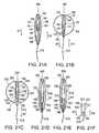
- FIGS. 1A-1C and 2 A- 2 Eshow portions and operation of a pessary including a body having a naturally occurring unexpanded shape, according to some embodiments of the present invention
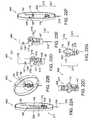
- FIGS. 3A-3E , 4 A- 4 C, 5 A- 5 D, 6 A- 6 B, 7 A- 7 B, 8 A- 8 B, 9 A- 9 C, 10 A- 10 C, 11 A- 11 C, 12 A- 12 H, 13 A- 130 , 14 A- 14 D, 15 A- 15 D, 20 A- 20 E, 21 A- 21 F, 22 A- 22 G, and 23 A- 23 Hshow alternative configurations and operation of the pessary of FIGS. 1A-1C and 2 A- 2 E, according to some embodiments of the present invention;
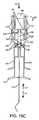
- FIGS. 16A-16B , 17 A- 17 B, and 18 A- 18 Bshow portions and operation of a pessary including an inflatable body, according to some embodiments of the present invention
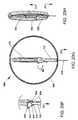
- FIGS. 19A-19Cshow portions and operation of a pessary including dual elongate elements, according to some embodiments of the present invention.
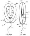
- FIG. 24A and 24Bshow a volumetric embodiment of the invention.
- the present inventionin some embodiments thereof, relates to devices and methods for treating pelvic organ prolapse and, more particularly but not exclusively, to vaginal support devices, and methods that aid in inserting the support devices into the vagina.
- the pessaryincludes two or more rib sections that push apart facing vaginal walls. As shown below, in many embodiments, the ribs are simply parts of a ring, which contact a vaginal wall. In an exemplary embodiment of the invention, the pessary has two stable states: a compressed state suitable for insertion and/or removal and an expanded state where the ribs press against the walls.
- the pessaryincludes an integrate state changing mechanism which changes the pessary from one state to another and/or locks the pessary in one or both states. Separate locks and state changing mechanism may be provided.
- one or more elastic elementsare provided to maintain the stability of the pessary and/or to urge the pessary to a stable state.
- multiple deployed statesare provided, for example, for adjustment of size and/or prolapse alleviation, as needed.
- the ribsare stiffened by the state changing mecahnism.
- one or more parts of the pessary, for example, the state changing mechanismare configured to become dysfunctional after one or more uses, for example, including included sections that support only one direction of relative motion, or including one or more pins that break during state change.
- the ribsare contained within a shape, for example, a ring.
- the ribscontact and apply substantial force to the vaginal walls for a length that is at least 20%, 30%, 40%, 50%, 60%, 70% or more of the total axial length of the device, or its non-pliable portions (e.g., not including a string or control cable or rod).
- the length of force application of each ribis at least 10 mm, 20 mm, 30 mm, 40 mm, 50 mm or shorter, intermediate or longer distances.
- the ribsare substantially rigid in form and location when in a deployed state.
- some part of the pessaryfor example, the rings or a section supporting or otherwise coupled to the ribs, can flex.
- prolapse alleviationis provided by a membrane or other element (e.g., state change mechanism) which extends between the ribs and prevents motion past it of a vaginal wall section.
- the ribsoptionally act as anchors and/or to stretch the vaginal wall.
- the pessaryis planar. In other embodiments, the pessary is non-planar and fills a volume within the vagina, for example, a volume of 2, 3, 4, 5, or more cm in height (e.g., along a general left-right symmetry plane of the body, and perpendicular to the vaginal axis).
- a pessaryis formed by using one or more state change mechanisms, as applied to two or more planar elements.
- such a structureis of an inflated element.
- a planar and/or a volumetric pessaryare made rotationally symmetric, for example, by rotation of 180 or 90 or 60 or 45 degrees a substantially same functional effect is achieved. This may assist in placement.
- the pessaryis not space filling, rather it is formed mainly of one or more rods or other elongated forms which provide the final geometry.
- the spaces between the elongate formsare optionally open and/or otherwise allow passage of vaginal secretions past the pessary.
- the pessarymay fill less than 40% 30%, 20%, 10% of a volumetric shape defined thereby.
- the pessaryis formed so that the vaginal walls tent on the pessary.
- no coveris provided.
- a coveris provided.
- the pessaryis inserted using an applicator.
- the applicatorchanges the state of the pessary.
- the pessaryis stored in the applicator in a tension reduced state.
- the applicatoris used to change the state of the pessary after insertion.
- Such an applicatormay also be used for pessaries without a state changing mechanism as described herein, and provide a potential advantage with respect to ease of use and/or self insertion.
- an applicator and/or the state changing mechanism and/or a tearing mechanism(e.g., which causes mechanical failure of the pessary by reduction of hydraulic pressure or mechanical disconnection or weakening), is used to provide ease of removal, for example, for self removal.
- the pessaryincludes a ring having a naturally occurring (in a rest state) substantially flat and planar compact shape and size that is suitable for insertion into a vagina.
- the ringis not-ring like in its resting shape, for example, being ovoid, for example, having a width to length ration of smaller than 1:2, 1:3, 1:5, 1:6, 1:10.
- the use of a flat compact shapeassists in insertion to the body.
- the use of a natural compact shapeallows the insertion to be provided without apply shape-maintaining forces on the device.
- the pessaryis elastic or pliable enough so it may be further manually compacted or distorted to assist in insertion.
- the pessarywhen deployed, extends out of a single plane, by, for example, 10%, 20%, 30% or intermediate or smaller amounts of an average or maximal thickness of the pessary.
- the ratio of thickness (in the plane) to diameteris smaller than for example, 1:3 (thickness to diameter), 1:4, 1:5, 1:6,1:8, 1:10 or intermediate or smaller ratios.
- the ringis configured to be maintained by a support element in a laterally expanded configuration.
- the ringassumes a predefined shape and size (such as a ring shape or generally polygonal annular shape), and exerts outward pressure on at least two opposite vaginal walls, optionally creating linear stretching, while creating a new shape of the intra-vaginal hollow, for example a rectangular shape.
- the pressure from the ringcauses the vaginal walls and apex to stiffen, thereby substantially supporting the prolapsed pelvic organ and relieving the discomfort caused by the prolapsed organ.
- the ringgives (e.g., the diameter lessens and/or ring bends out of a more planer shape) only a small amount or not at all when in an expanded shape, for example, less than 5 mm, less than 3 mm, less than 1 mm.
- the ringis elastically maintained in its expanded shape and can give a greater amount, for example, 6 mm, 7 mm, 8 mm, 9 mm or more.
- the support elementis encapsulated within the ring.
- the support elementis outside of the body of the ring, for example, forming a chord.
- At least 50%, 70%, 85% or intermediate percentages by volume of the support elementare contained within the outer periphery of the ring-like body.
- At least 30%, 50%, 70%, 80% or intermediate percentages or more of the volume enclosed by the pessary when in an expanded shapeis a void, optionally a void accessible form outside the pessary, optionally void that connects two opposing faces of the pessary.
- the ringincludes a resilient material that naturally maintains the compact configuration.
- the ring's naturally occurring compact shapecomprises an oval, a triangle, or a rhomboid.
- the ringin the expanded configuration, includes an aperture of sufficient size to allow passage of vaginal fluids thereby increasing user comfort and preventing fluid buildup that can result in malodors or infections.
- the outer periphery of the ringin the expanded configuration, assumes a circular, an ovoid or a rhomboid shape.
- the support elementincludes dual bars that are centrally connected at their first ends, and rotatably connected at their second ends to the ring. With the ring in the collapsed position, the bars are in a folded position.
- the compact ringhas a long axis which, when pressed, causes the ring to expand as the bars extend.
- the barsinclude locking mechanisms, for example extensions in the rotatable connections at the second ends of the bars, which maintain the bars in the extended position, thereby maintaining the ring in the expanded configuration.
- the pessaryincludes a string connected to the central rotatable connection of the dual bars.
- the stringextends from the vagina, such that pulling the string by the user causes the bars to unlock. With the bars unlocked, the resilience of the ring causes the bars to fold, and the ring assumes the naturally occurring substantially flat and planar compact shape, alternatively referred to herein as an unexpanded shape; a configuration that is easily removed from the vagina.
- the support elementincludes telescoping tubes (or side by side bypassing tubes) which, when the ring is in the compact configuration, are in a non-telescoped and extended position.
- the tubesWith the ring in the expanded configuration, the tubes telescope, one within the other (or side by side), and locks between the tubes maintain the telescoped position so that the pessary is maintained in the expanded configuration.
- Unlocking the locksallows the ring to return to the compact configuration while the tubes extend with respect to each other to the non-telescoped configuration.
- the support elementsis configured to be unlocked by application of minimal force, with some unlocking being provided by the resilience and natural shape of the ring.
- unlocking of the support elementrequires application of force for a significant change in shape of the support element, for example, a movement of at least one part of the support element relative to other parts, of at least 5 mm, 10 mm, 20 mm or more.
- the support element lockcomprises a “U” shape element having prongs that engage receptacles to lock the tubes in the telescoped position. Pulling a string connected to the U shape element causes the prongs to disengage from the receptacles so that the ring returns to a naturally occurring compact configuration.
- interconnected prongsextend laterally from lateral aspects of a diamond-shaped spring. Pulling a string connected to the diamond causes the diamond shape to narrow, disengaging the prongs from the receptacles, allowing the ring to return to the compact configuration.
- prongsextend laterally from upper and lower ends of a spring that is shaped like an “H”. A slide bar between the arms of the “H” presses the prongs into receptacles, thereby locking the ring in the expanded configuration.
- Pulling a string connected to the slide barcauses disengagement of the upper prongs of the H spring from the upper receptacles, unlocking and allowing movement of the inner tube with respect to the outer tube and the ring returns to the compact configuration.
- the lockincludes a wheel connected to a lower portion of the ring.
- the wheelincludes a rim that is engaged by edges of a semi-circular piece attached to an upper portion of the ring.
- edges of the semi-circular pieceinclude a narrow transverse dimension that engages the wheel rim. These edges optionally include a release portion having a wide transverse dimension that releases the wheel rim, when so disposed, to allow the ring to return to the compact configuration.
- the semi-circular piecesare rotated so that the release portion of the semi-circular piece is aligned with the wheel rim and the wheel is released.
- the wheeldisengages from the semi-circular piece, and the telescoped inner and outer tubes, along with the semi-circular piece, retract upward.
- the wheelretracts downward and remains connected to the lower part of the ring which returns to the compact configuration.
- the lockcomprises a wheel having a lever-like extension, and wide and narrow transverse dimensions.
- the wheelis rotatably attached to the large diameter tube.
- the small diameter narrow tubeincludes engagement rails which engage the narrow wheel dimension to maintain the tubes in the telescoped configuration.
- the leveris pulled to rotate the wheel so that the wide release portion aligns with the engagement rail, releases the engagement rail, and allows the ring to return to the compact configuration.
- the support element lockcomprises a one-way valve that causes a vacuum to form within the tubes.
- the vacuumlocks the tubes and maintains the expanded shape of the ring. Releasing the one-way valve allows the ring to assume the compact position with the telescoped tubes extended.
- the support element lockcomprises a collapsible elongate ratchet that extends from an upper ring portion that interfaces with a ratchet lock extending from a lower ring portion.
- the collapsible elongate ratchetincludes a collapsible tubular chamber that slidably surrounds a rod. With the rod in the tubular chamber, the chamber and the ratchets are maintained in a laterally expanded position.
- the ratchet lockratchets along the ratchets until the ring is fully expanded and the ratchet lock is locked in place by the ratchets.
- the rodis pulled out of the tubular chamber so the ratchets collapse inward and no longer interface with the ratchet lock.
- the ringreturns to the compact configuration while the prongs slide past the collapsed ratchets.
- a dual arm pessaryfor supporting a prolapsed organ.
- the dual arm pessaryincludes two operatively associated elongate elements having at least two configurations: a collapsed configuration having a cumulative size suitable for insertion into a vagina, and an expanded configuration wherein each of the two elements are separated by a distance, and contact at least a portion of the vagina to support at least a portion of a prolapsed organ.
- the dual arm pessaryincludes a support element configured to maintain the distance between the two elements in the expanded configuration. Pulling the support element causes the arms to return to the compact configuration.
- the pessaryis in the form of a coil (e.g., coaxial with the vagina), or includes ribs which lie along such a coil, and optionally supported from within.
- the pessary embodiments presented aboveinclude an applicator configured to press the ring into an expanded shape and release the deployed pessary within the vagina. With the ring locked in the expanded configuration with one of the locking embodiments explained above, the applicator is released from the pessary, allowing removal from the pessary embodiment so that the applicator may be pulled out of the vagina.
- the pessary applicatormay be operated without the user touching the vagina or the surrounding skin.
- an inflatable pessaryfor supporting a prolapsed organ.
- the inflatable pessaryincludes an inflatable chamber having at least two inflatable arms, the inflatable chamber having at least two configurations: an uninflated configuration having a size suitable for insertion into a vagina; and an inflated configuration in which at least a portion of the inflatable chamber contacts a portion of the vagina, and supports at least a portion of a prolapsed organ.
- the inflatable pessaryincludes an inflatable chamber having a one-way valve that connects to an inflator, the one-way valve remaining with the inflated inflatable chamber in the vagina.
- the one-way valveconnected to a string, maintains the inflatable chamber in the inflated configuration. Pulling the string opens the valve, causes release of inflation fluid contained within the inflatable chamber, whereby the inflation chamber becomes uninflated.
- the inflatable chambercomprises two arms extending from the inflator that assume a “U” shape in the inflated configuration. In other embodiments, the inflatable chamber comprises two arms that extend in a circular configuration from the inflator, forming a substantially complete circle in the inflated configuration.
- the pessary embodiments presentedare disposable, while in other embodiments, the pessary embodiments are suitable for reuse.
- the pessary embodimentsare optionally inserted for a relatively short period of time, for example during the day, which may reduce chances of infection and pressure ulcers associated with existing art devices.
- a method for supporting a pelvic organincluding placing a device having a planar compact shape in a vagina, expanding the ring to support at least one prolapsed organ, and supporting the expanded device with a support structure.
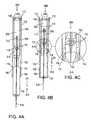
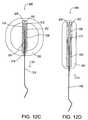
- FIG. 1Ashows a portion of an embodiment of the present invention of a pessary 300 comprising a ring 302 having a rhomboid compact configuration for insertion into the vagina.
- ring 302expands to press the vaginal walls and thereby substantially alleviates pelvic organ prolapse.
- pessary 300in the compact configuration, may have an oval shape ( FIG. 1C ) or even a triangular shape ( FIG. 2E ).
- the various shapes for pessary 300 in the compact configurationare determined by, for example, ease of insertion and/or the desired shape of pessary 300 in the expanded configuration.
- pessary 300includes a support mechanism that spans and supports ring 302 in the expanded configuration; some sample embodiments of the many possible configurations for the support mechanism being shown in FIGS. 2A-D .
- a support mechanism 309alternatively referred to as locking mechanism 309 , comprises two arms 306 that are rotatably connected at hinge 314 , alternately referred to as rotation axis 314 .
- a string 318is attached to the rotatable connection that serves to unlock arms 306 , as will be explained below.
- Arms 306are attached to limiters 310 along ring 302 with peripheral hinges 312 .
- ring 302in the compact configuration, is inserted into a vagina 311 with arms 306 folded.
- hinge 314is pressed in a direction 319 to cause ring 302 to expand while arms 306 unfold ( FIG. 2B ).
- Ring 302achieves a maximally expanded configuration ( FIG. 2C ) in which support curves 301 and 303 press laterally against the tissue of opposite and lateral aspects of vagina 311 .
- limiter edges 322press against arms 306 , and lock arms 306 to maintain support mechanism 302 as a span across ring 302 while forming an angle having an apex above a transverse line k-k.
- the following exemplary methodis provided, which may affect size, resilience and/or exact shape of the device. While laterally pressing the tissue of vagina 311 , noted above, support curves 301 and 303 cause the tissue of vagina 311 to stiffen. The lateral pressure from support curves 301 and 303 causes flattening and stretching of anterior and posterior walls of vagina 311 , so that a prolapsed apex of vagina 311 is stretched upward.
- flattening and stretching of anterior and posterior walls of vagina 311reduces prolapse associated with one or more external organs comprising the bladder, rectum, small intestine, and/or uterus.
- the pessaryoptionally includes a membrane or cross-element which directly supports organs.
- the pessaryis optionally volumetric and fills a space in the vagina.
- space fillingstill includes passages for vaginal secretions therepast (including possibly therethrough).
- Pessary 300in some embodiments thereof not only can be used to treat prolapse of vagina 311 , but also to assess the need for surgical treatment in treating the prolapse. A positive result with pessary 300 in place may allow the user to forgo surgery that often presents a risk of untoward sequella.
- Pulling application string 318 in a direction 321causes hinge 314 to move in direction 321 so that arms 306 unlock by disengaging from limiter edges 322 .
- Unlocked armsinitially form an angle having an apex below line k-k as seen in FIG. 2B . Due to the friction between ring 302 and the walls of vagina 311 , pulling string 318 to unlock arms 306 will not substantially move ring 302 with respect to the walls of vagina 311 .
- Hinges 312optionally connect arms 306 to limiters 310 in a manner that allow arms 306 to move only in directions 319 and 321 , while being substantially limited in moving along a cross sectional plane through the upper surfaces of support curves 301 and 303 ; a substantially planar movement.
- Limiters 310are optionally attached to ring 302 in optional recesses 308 so that surface of limiters 310 is flush with the surface of ring 302 .
- pessary 300includes flexible materials that partially cover arms 306 and/or limiters 310 which may be replaced in between uses of pessary 300 , thereby increasing ease of maintaining hygiene of pessary 300 .
- pessary 300is supplied with a replaceable tubular cover that installs around ring 302 and/or limiters 310 which may be replaced in between uses of pessary 300
- the materials used in ring 302may optionally comprise soft and/or flexible materials that increase user comfort; for example a rubber material, a polyurethane, a thermoplastic elastomer, a cardboard material, or a polymer.
- Pessary 300may include an optional soft coating to enhance user comfort, for example a low shore silicone.
- ring 302includes indents 320 that act as a resilient living hinge. Indents by a manufacturer of pessary 300 can be varied in depth, for example to facilitate easier opening of ring 302 .
- ring 302includes an internal flexible support frame 304 ( FIG. 1A ) comprising, for example: a metal, a nylon material, polypropylene and/or polyethylene.
- internal support frame 304may allow ring 302 to be manufactured with softer cover materials that are less resilient.
- support frame 304is optionally configured to provide stiffness needed to maintain ring 302 in the compact configuration.
- compact ring 302has a substantially planar configuration with a lateral dimension of between about 20 and 40 millimeters to facilitate easy and painless vaginal insertion.
- Expanded ring 302optionally attains a round shape ( FIG. 1B ) or alternatively, an oval shape or a rhomboid shape ( FIG. 2C ).
- expanded ring 302may have an average diameter of between about 50 to 120 millimeters depending, for example on the desired final shape and size of the cavity of vagina 311 .
- pessary 300differs substantially from other devices that insert into vagina 311 .
- expanded pessary 300typically places the greatest pressure above the position of a bladder neck 115 . Additionally, this pressure is directed against the lateral walls of vagina 311 .
- a urinary continence deviceis configured to place the greatest pressure on bladder neck 115 , which is located along an anterior position of vagina 311 .
- ring 302naturally maintains the laterally outward configuration.
- arms 306pull ring 302 into the compact configuration. Maintaining tension on string 318 keeps ring 302 in the compact configuration, ( FIG. 2A ), allowing insertion and removal from vagina 311 .
- hinge 314may include an optional spring mechanism to aid in maintaining arms 306 folded and ring 302 compact.
- ring 302may have alternative configurations, just one of the many alternative configurations now being presented.
- FIG. 3Ashows an exploded view of a pessary assembly 800 in which ring 302 includes support frame 304 as described above, allowing for the use of softer cover materials around support frame 304 , noted above.
- Limiters 310are attached directly to support frame 304 and emerge from slots through ring 302 . In this configuration, arms 306 exert direct pressure on support frame 304 which governs the expansion of ring 302 .
- pessary 300is included with an applicator that is operated by a user to expand ring 302 within vagina 311 .
- an applicatorthat is operated by a user to expand ring 302 within vagina 311 .
- an applicator 100includes a housing 140 which has an ovoid cross sectional profile along the transverse plane; a profile configured to match the user anatomy, as vagina 311 is parted during insertion of pessary assembly 800 .
- housing 140includes applicator arms 110 which include a first snap 142 and a second snap 112 , respectively, which removably snap into receptacles 149 on either side of the upper portion of ring 302 .
- ring 302is attached to applicator 100 , as shown in FIGS. 3A and 3D .
- the bottom portion of ring 302is set in housing 140 , first snap 142 and second snap 112 snap into receptacles 149 .
- the first and third fingersare placed in convex recesses 102 , on the front and back of housing 140 , while the user's second finger pushes plunger 106 through housing 140 in direction 319 . Movement of plunger 106 causes a hollow rod 108 to press arms 306 in direction 319 , thereby extending arms 306 as shown in FIGS. 3D-3E .
- Arms 306extend until ring 302 attains the expanded shape shown in FIG. 3C and arms 306 form an angle having an apex above line K-K, as noted above.
- applicator arms 110are pushed outwardly, as a result of movement of an upper slope 118 of plunger 106 over inner projections 116 ( FIGS. 4A-4C ) on either side of applicator arms 110 .
- upper slope 118passes inner projections 116 , the walls of housing 140 bulge outward, and applicator arms 110 move apart, releasing ring 302 .
- Applicator 100( FIG. 3A ) is removed from ring 302 and out of vagina 311 leaving expanded ring in vagina 311 as shown in FIG. 3C .
- the support mechanismmay comprise sliding tubular components, the following description relating to just one of the many embodiments of sliding support mechanisms.
- FIGS. 5A-5Dshow embodiments of a sliding pessary 810 having a smaller diameter tube 156 that slides into a larger diameter tube 152 .
- Larger diameter tube 152is attached at an upper connector portion 159 on ring 302 , and smaller diameter tube 156 is connected to a lower connector portion 158 on ring 302 .
- FIGS. 5C-5Dshow sliding pessary 810 assembled on applicator 100 with string 318 emerging from hollow tube 106 which is connected to plunger handle 105 .
- sliding pessary 810is placed in the vagina.
- Plunger handle 105is pressed in direction 319 so that the flat base presses against lower connector portion 158 , causing smaller diameter tube 156 to telescope into larger diameter tube 152 , resulting in the above-noted expansion of ring 302 .
- FIGS. 7A-9Bshow sliding pessary 810 loaded on applicator 100 .
- the upper portion of applicator arm 110has a projection 111 that faces inward.
- projection 111is secured against a circumferential edge 154 , thereby holding larger tube 152 in position as plunger handle 105 is pressed against smaller tube 156 to cause expansion of ring 302 .
- inward projectionmay be alternatively referred to herein as a “medially facing” projection, and a motion that moves inward with respect to ring 302 may be referred to as a “medial motion”.
- FIG. 8Bshows a cut section of sliding pessary assembly 810 with ring 302 in applicator 100 , prior to vaginal insertion.
- plunger handle 105has been pressed in direction 319 to cause smaller tube 156 to move in direction 319 causing expansion of ring 302 .
- the upper portion of smaller diameter tube 156has a round ring 163 and a recess 159 .
- Sliding pessary assembly 810includes any one of a variety of locking mechanism embodiments that locks tubes 152 and 156 in the telescoped configuration; the following being just one example of the many possible locking mechanism embodiments.
- Tabs 169contract inward from apertures 148 as prongs 164 move inward into recess 159 , and tubes 152 and 156 become locked in position with ring 302 in the expanded position ( FIG. 9A ).
- flat section 107reaches sloped prongs 116 on the inner aspect of applicator arms 110 . Movement of flat section 107 pushes both arms 110 outward so that protrusions 111 depart from rim 154 ; following which applicator 100 may be disengaged from sliding pessary 810 .
- ring 302Due to the dimensions of expanded ring 302 , ring 302 remains within the vagina while applicator 100 is removed, and string 318 protrudes outside vagina 311 for removal of ring 302 .
- apertures 148 and/or recess 159may be of a sufficient size to allow some movement of prongs 164 so that larger tube 152 moves with respect to smaller tube 156 . Movement of tubes 152 and 156 may allow, for example, oscillation within ring 302 that may contribute to user comfort for example when the walls of vagina 311 are less flexible, for example following prior surgical intervention.
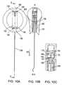
- string 318is pulled in direction 321 as shown in FIGS. 10A-C .
- An upper string portion 168is attached to unlocking mechanism 170 which has a sloped edge 172 .
- unlocking mechanism 170moves in direction 321 with the wider portion of sloped edge 172 pushing aside tabs 160 and prongs 164 , hence disengaging smaller tube 156 from larger tube 152 .
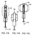
- FIGS. 11A-11Cshow still another embodiment of a pessary assembly 820 in which expanded ring 302 forms an aperture having four curves forming a clover-leaf shaped aperture.
- the support structuremay include one or several ratchet mechanisms, the following description being directed toward just one such embodiment.
- a ratchet pessary 890shown in FIGS. 12A-12H , includes an anchor 200 within the upper portion of ring 302 and a flexible tube 202 extending downwardly therefrom. Flexible tube 202 has multiple ratchets 206 that project outward therefrom.
- a ratchet lock mechanism 216includes upper projections 212 that resiliently ratchet along ratchets 206 to expand ring 302 . Upper projections 212 then enter upper openings 213 and maintain ring 302 in the expanded configuration.
- Insertion of ratchet pessary 890may take place using applicator 100 ( FIGS. 12E-12H ), which has a flat surface 120 ( FIG. 12H ) that presses the lower portion of ring 302 to cause outward expansion as the upper portion of ring 302 is held in place by projections 112 .
- a cavity 209 ( FIG. 12C-D ) running through flexible tube 202contains a spacer 204 which slides out of cavity 209 .
- String 318is connected to the distal end of spacer 204 .
- the pessary support elementmay comprise any one of several vacuum actuated support elements; the following being just one such pessary embodiment.
- FIGS. 13A-13GShown in FIGS. 13A-13G is a vacuum pessary 895 , in which smaller tube 356 is contained within larger tube 352 in an extended position ( FIG. 13B ), as noted above.
- smaller tube 356configured as a piston, is moved in direction 319 into larger tube, forcing air out of a chamber 353 through a one way valve 350 .
- FIGS. 13C-13Dshow details of vacuum pessary 895 in which larger tube 352 is docked into a proximal docking slot 340 and smaller tube 356 is docked at docking slot 344 .
- An “O” ring 357maintains a vacuum seal between tubes 352 and 356 so that vacuum pessary 895 maintains ring 302 in the expanded configuration until the user chooses to remove vacuum pessary 895 .
- the lower end of smaller tube 356has a vacuum release plug 360 .
- string 318which is connected at point 359 to vacuum release plug 360 , pulls plug 360 out of a plug receptacle 358 ( FIG. 13A ), thereby releasing the vacuum in vacuum chamber 353 .
- FIGS. 13E-Fshow details of vacuum release plug 360 including a narrow neck 363 connected to a disc 364 having air passages 362 therethrough.
- a plug body 371is pressed into and forms a seal with a plug receptacle 361 .
- plug body 371dislodges from plug receptacle 361 so that disk 364 is positioned at the end of plug receptacle 361 , allowing air to flow into chamber 353 through air passages 362 .
- Disk 364cannot be fully dislodged from plug receptacle 361 , so further pulling of string 318 will pull vacuum pessary 895 out of the vagina.
- the supports that maintain ring 302 in the expanded positionare integral to ring 302 and do not span across the center of ring 302 . Just one of the many possible configurations of integrated supports is now presented.
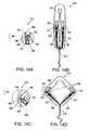
- FIGS. 14A-14DShown in FIGS. 14A-14D is an integrated support pessary 910 in which first and second support locks 392 are located at support curves 301 and 303 , respectively.
- first and second support locks 392are located at support curves 301 and 303 , respectively.
- integrated and integratedrefer to support locks 392 that are located on or within ring 302 and/or do not span across the center of ring 302 in the expanded configuration.
- Support lock 392shown in detail in FIGS. 14A and 14C , includes a moveable arm 380 which is rotatably connected to a pivot 388 . To expand ring 302 , arm 380 is rotated approximately 90 degrees in a clockwise direction 394 with respect to a pivot support 390 .
- Rod 381 with prong 382 at its distal endis pressed forward by a spring 384 , so that prong 382 then enters into a slot 386 , and locks arm 380 in position so that ring 302 is maintained in the expanded configuration ( FIG. 14D ).
- integrated support pessary 910is shown with two support locks 392 , thereby forming ring 302 into a rhomboid expanded configuration, integrated support pessary 910 may be configured with three, four or even six or more support locks 392 so that ring 302 may attain any one of many configurations, for example a hexagonal expanded shape.
- string 318is pulled.
- An end of string 318 connected at a point 393 to rod 381causes spring 384 to compress, thereby pulling prong 382 out of slot 386 .
- FIGS. 15A-15DAn alternative embodiment of integrated support pessary 910 is shown in FIGS. 15A-15D in which a prong 400 has a point 402 while arm 380 includes a first stop 404 and a second stop 406 .
- the support mechanismmay have many alternative locking configurations; the following embodiment presenting just one such embodiment.
- FIGS. 20A-20Bshow an alternative lock pessary 940 with ring 302 in the collapsed configuration and prongs 157 projecting through lower openings 177 .
- Alternative lock pessary 940is deployed by compressing ring 302 while a bullet projection 59 maintains alignment as tubes 152 and 156 telescope.
- prongs 157Upon attaining full expansion of ring 302 , prongs 157 align with, and lock into, apertures 148 , thereby locking tubes 156 and 152 in the telescoped configuration ( FIG. 20C ).
- a pessary supportmay have a support structure having two different positions when ring 302 is in the compact configuration; the following presenting just one such embodiment.
- FIGS. 21A-21Fshow a dual compact position pessary 830 having an “H” shaped spring 151 ( FIG. 21F ), including upper prongs 123 and lower prongs 155 . Juxtaposed on H spring 151 is a slide bar 153 that slides in direction 321 prior to compaction of ring 302 ( FIG. 21C ).
- Slide bar 153includes a wedge 199 on an upper end, and string 318 attached to a lower end.
- ring 302is in a compact configuration with tubes 252 and 256 extended, and upper prongs 123 are engaged with aperture 148 in inner tube 252 .
- H spring 151is substantially in the middle of ring 302 along the longitudinal axis of ring 302 ; constituting a first disengaged position of H spring 151 .
- lower prongs 155engage neither tube 252 nor 256 .
- Ring 302is then compressed, causing outer tube 256 to move in direction 319 , past upper prongs 123 until lower prongs 155 engage lower apertures 196 which are in the lower end of outer tube 256 .
- Upper ends of the H springremain in apertures 148 ; thereby maintaining the ring in the expanded position with “H”-shaped spring 151 in the lower portion of outer tube 256 .
- “H”-shaped spring 151occupies a second disengaged position in the lower portion of outer tube 256 , while inner tube 252 has retracted in upward direction 319 .
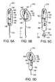
- FIGS. 22A-Gshow a disengageable lock pessary 840 in which a locking mechanism 277 , shown in detail in FIG. 22G , includes a semi-circular piece 175 that rotates in a direction 179 around a wheel 171 .
- Semi-circular piece 175includes an inner track 824 , alternatively referred to as a trough, having an engaging portion 826 that includes a narrow transverse dimension that engages wheel 171 when wheel 171 is disposed in engaging portion 826 .
- Inner track 824additionally includes a release portion 822 having a wide transverse dimension that releases wheel 171 when wheel 171 is disposed in release portion 822 .
- semi-circular piece 175is an extension of small diameter tube 156 which slides in direction 319 into larger diameter tube 152 .
- Wheel 171is connected to ring 302 , optionally via a connection 147 .
- ring 302is compressed until attaining a configuration shown in FIG. 22B in which prong 157 optionally engages aperture 148 and maintains the telescoped expanded configuration.
- a flip lever pessarypresented below, comprises still another embodiment of many possible alternative rotatable locking mechanisms that disengage to allow collapse of ring 302 .
- FIGS. 23A-23Hshow a flip lever pessary 880 including a wheel 180 having a lever 181 .
- Wheel 180is rotatably connected to large diameter (lower) tube 152 .
- wheel 180includes a curved inner facing rim 834 which has an engaging portion 836 with a narrow transverse dimension; and a release portion 832 with a wide transverse dimension.
- curved periphery 834is configured to be engaged with snap connectors 182 positioned at the end of small diameter tube 156 .
- ring 302is compressed until inner facing rim 834 compresses and passes snap connectors 182 and enters inner tube recesses 184 .
- Snap connectors 182return to an uncompressed configuration to lock inner facing rim 834 in inner tube recesses 184 ; thereby locking ring 302 in the expanded position.
- Some embodiments of the inventionmay include alternative expanding portions to ring 302 , for example an inflatable body; the following describing just one embodiment of an inflatable pessary.
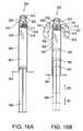
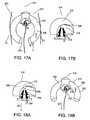
- FIGS. 16A-16Bshow an inflatable pessary 920 having an inflatable body 511 that inflates with various fluids 508 stored in fluid chamber 502 .
- Fluidsmay include a gas, for example air or nitrogen; or a liquid such as water.
- inflatable body 511in the unexpanded configuration, is substantially contained within a housing 514 .
- rims 504 on fluid chamber 502are held between the user's second and third fingers while the thumb presses a plunger 506 .
- housing 514is connected to fluid chamber 502 through a one way valve 516 that optionally controls the rate of fluid entry or exit from inflatable body 511 .
- one way valve 516may protect the user from discomfort that may result from overly-rapid inflation.
- Housing 514is typically configured to allow portions of inflatable body 511 to expand external to housing 514 during and following expansion.
- housing 514includes side openings 522 that allow pessary arms 532 to exit housing 514 and expand.
- Fluid chamber 502is optionally connected to housing 514 with a quick release connection 518 , for example a bayonet lock. Following inflation of inflatable body 511 , quick release connection 518 is activated by the user and fluid chamber 502 is disconnected from housing 514 for disposal, or for future use according to some embodiments. Upon disconnection, one way valve 516 prevents deflation of body 511 . Housing 514 typically remains together with expanded inflatable body 511 in the vagina while inflatable pessary 920 is in use.
- a quick release connection 518for example a bayonet lock.
- fluid chamber 502may be a canister of compressed gas and supplied to the user while it is connected to housing 514 .
- fluid chamber 502can be disposed of following deployment of inflatable pessary 920 .
- a space 509is created between one way valve 516 and supply channel 512 , allowing fluid to be released, thereby deflating inflatable body 511 .
- string 318is pulled with a long, steady pull in direction 321 to draw inflatable pessary 920 out of the vagina.
- pessary arms 532may attain any one of many peripheral shapes including an open “V” shape, or a circular or rhomboid shape in which the ends of pessary arms 532 are in close proximity or even contacting each other.
- the shape of inflatable body 511may be chosen, for example, based upon which organ is causing the prolapse.
- inflatable body 511may be configured to form a substantially full circle or rhomboid; while for treating a prolapsed vaginal vault, arms 532 may be shorter, for example as shown in FIG. 16B .
- the usermay be allowed to control the amount of pressure exerted by arms 532 against the walls of the vagina. For example, the user may push plunger 506 to a position 542 to expand inflatable body 511 so that arms 532 exert a minimal level of pressure. Upon determining that greater pressure is desirable to control organ prolapse, the user may optionally press plunger to a position 544 or a position 546 to achieve appropriate pressure.
- fluid chamber 502may contain a user-specific volume of fluid.
- the volume of fluid in fluid chamber 502may be determined by the user or a caregiver based upon user comfort with respect to pressure exerted by arms 532 and/or optimal treatment of organ prolapse.
- fluid chamber 502may be supplied to the user separately and unconnected to housing 514 , in a dispenser having a syringe-like configuration.
- the usermay draw the appropriate volume of water into fluid chamber 502 , for example from a water cartridge, prior to connecting fluid chamber 502 to housing 514 .
- fluid chamber 502may have an inlet (not shown) through which the user fills fluid chamber 502 with an appropriate volume of gas from a separate compressed gas cartridge.
- a pessaryincludes dual parallel arms that separate during expansion, the following being a description of just one such one embodiment.
- FIGS. 19A-19CShown in FIGS. 19A-19C is a dual arm pessary 950 comprising a housing 540 having openings 532 .
- Ann supports 524pass through openings 532 and optionally rotatably connect to connectors 522 on arms 520 .
- housing 540Within housing 540 is a rack 598 , connected to string 318 .
- the teeth on rack 598engage, within housing 540 , with the teeth on pinions 528 on arm supports 524 .
- dual arm pessary 950is connected to an applicator 500 having an applicator housing 554 containing an applicator plunger 556 .
- rack 598moves in direction 319 causing arm supports 524 to rotate in a downward direction 538 with respect to housing 540 ; and arms 520 move outward from housing 540 .
- the outer surfaces of arms 520are separated by a distance of 25 to 45 millimeters in the unexpanded configuration, and by a distance of 50-120 millimeters in the expanded configuration.
- applicator 500is connected to pessary 950 with a quick disconnection mechanism as described above and, following deployment, applicator 500 is easily disconnected from dual arm pessary 950 . Following deployment, applicator 500 is disconnected from dual arm pessary 950 and disposed of or cleaned for reuse.
- dual arm pessary 950is stabilized in position inside the vagina and string 318 is pulled in direction 321 .
- rack 598moves in direction 321 , causing arm supports 524 to rotate in an upward direction 552 so that arms 520 move toward housing 540 .
- applicator 500may be disassembled and cleaned for reuse so that dual arm pessary 950 may be repeatedly deployed.
- dual arm pessary 950is configured for a single use.
- rack 598may include cutout areas 558 so that once collapsed, the teeth pinions 528 cannot be reengaged with rack 598 and dual arm pessary 950 must be discarded.
- Dual arm pessary 950may be supplied in a variety of configurations to treat, for example, different vaginal sizes and/or different prolapsed organs.
- arms 520may be relatively short and wide.
- arms 520may be relatively long and narrow.
- dual arm pessary 950may be configured with two, three, or four or more sets of arms 520 with each set of dual arms 520 having, for example, a different final distance from housing 540 ; for example, each set configured for treating a different prolapsed organ in users suffering from multiple organ prolapse.
- FIGS. 24A and 24Bshow an example of a pessary which is not planar.
- the basic shapee.g., ring
- the sides of the ringmay curve up or down
- the sides of the ringmay be thicker than the leading edge of the ring and/or the pessary may curve along its main axis (e.g., the vaginal axis).
- main axise.g., the vaginal axis.
- FIGS. 24A and 24Bshow a pessary 2400 in which the pessary is space filling.
- a plurality of arc sections 2402 , 2404 , 2406 and 2408define a generally spherical, rectangular or ovoid shape when expanded ( FIG. 24A ).
- FIG. 24 bWhen in a compressed state ( FIG. 24 b ), all trans-axial dimensions of the pessary are small, to facilitate delivery and/or fitting into an applicator.
- the basic structure of pessary 2400is that of multiple intersecting rings, each formed of two of arcs 2402 , 2404 , 2406 and 2408 .
- two actual ringsare used, optionally one with a diameter greater than the other.
- Other number of arcsmay be used as well, for example, 5 and/or arcs that do not share flat planes as pairs.
- the pessarydirectly supports one or more prolapsed organs additionally or alternatively to stretching the vaginal wall in multiple directions as some of the above embodiments.
- a plurality of stacked (e.g., with their planes parallel to each other) rings (or other shapes)are provided, to provide space filling.
- a single state changing mechanism 2416is used for multiple orthogonal expansion directions. Any of the state change mechanism described above may be used.
- an optional string 2418can be used to selectively lock or unlock (in one or more positions) an outside tube 2410 to an inside telescoping element 2414 , optionally via a lock 2412 (e.g., a window in which one of two or more elastic protrusions of element 2414 can exit and engage).
- each arc or pair of arcshas a separate state changing mechanism, for example, as shown above for state changing mechanism that are wholly enclosed in the rings.
- the pessaryis covered by a cover and/or includes a membrane between at least some of the arcs, so as to be more space filling.
- the pessaryincludes large passages for vaginal secretions therepast (including therethrough).
- pessaryis intended to include all such new technologies a priori.
- the term “about”refers to ⁇ 10%.
- compositions, method or structuremay include additional ingredients, steps and/or parts, but only if the additional ingredients, steps and/or parts do not materially alter the basic and novel characteristics of the claimed composition, method or structure.
- range formatis merely for convenience and brevity and should not be construed as an inflexible limitation on the scope of the invention. Accordingly, the description of a range should be considered to have specifically disclosed all the possible subranges as well as individual numerical values within that range. For example, description of a range such as from 1 to 6 should be considered to have specifically disclosed subranges such as from 1 to 3, from 1 to 4, from 1 to 5, from 2 to 4, from 2 to 3 to 6 etc., as well as individual numbers within that range, for example, 1, 2, 3, 4, 5, and 6. This applies regardless of the breadth of the range.
- methodrefers to manners, means, techniques and procedures for accomplishing a given task including, but not limited to, those manners, means, techniques and procedures either known to, or readily developed from known manners, means, techniques and procedures by practitioners of the chemical, pharmacological, biological, biochemical and medical arts.
- treatingincludes abrogating, substantially inhibiting, slowing or reversing the progression of a condition, substantially ameliorating clinical or aesthetical symptoms of a condition or substantially preventing the appearance of clinical or aesthetical symptoms of a condition.
Landscapes
- Health & Medical Sciences (AREA)
- General Health & Medical Sciences (AREA)
- Public Health (AREA)
- Biomedical Technology (AREA)
- Heart & Thoracic Surgery (AREA)
- Vascular Medicine (AREA)
- Life Sciences & Earth Sciences (AREA)
- Animal Behavior & Ethology (AREA)
- Veterinary Medicine (AREA)
- Engineering & Computer Science (AREA)
- Urology & Nephrology (AREA)
- Reproductive Health (AREA)
- Cardiology (AREA)
- Oral & Maxillofacial Surgery (AREA)
- Transplantation (AREA)
- Orthopedics, Nursing, And Contraception (AREA)
- Surgical Instruments (AREA)
- Heterocyclic Carbon Compounds Containing A Hetero Ring Having Oxygen Or Sulfur (AREA)
- Nitrogen And Oxygen Or Sulfur-Condensed Heterocyclic Ring Systems (AREA)
Abstract
Description
- i) Cystocele, the leading form of pelvic organ prolapse, wherein the bladder drops into the vagina and may be associated with urination problems;
- ii) Rectocele, wherein the rectum herniates into the vagina and may result in difficulty and/or pain with defecation;
- iii) Enterocele, wherein the small intestine prolapses into the vagina;
- iv) Uterine prolapse wherein the uterus drops downward into the vagina and is often associated with complications related to childbirth; and
- v) Vaginal vault prolapse, wherein the top portion of the vagina, the apex, loses its natural shape and drops down into the lower vaginal canal, and may occur in women who had a hysterectomy.
| WO 9601084: | Inflatable Vaginal Pessary; |
| GB 235218: | Inflatable Pessary; |
| FR 2843700: | Rehabilitation Device for Urinary and Faecal |
| Continence; | |
| WO 03047476: | Vaginal Pessary; |
| GB 1115727: | Apparatus Controlling Incontinence in the |
| Female; | |
| U.S. Pat. No. 5,224,494: | Vaginal Pessary; |
| U.S. Pat. No. 6,158,435: | Pessary; |
| US 2003149334: | Vaginal Pessary; |
| JP 6133996: | Pessary for Treating Prolapse of Uterus; |
| U.S. Pat. No. 4,823,814: | Pessary; |
| U.S. Pat. No. 5,771,899: | Pessary; |
| U.S. Pat. No. 5,894,842: | Pessary for Treating Vaginal Prolapse; |
| U.S. Pat. No. 6,158,435: | Pessary; |
| U.S. Pat. No. 6,216,698: | Flexible Pessary; |
| U.S. Pat. No. 6,503,190: | Vaginal Pessary; |
| U.S. Pat. No. 6,808,485: | Compressible Resilient Vaginal Incontinence |
| Insert; and | |
| U.S. Pat. No. 7,036,511: | Vaginal Pessary. |
- (a) a body including at least two rib sections adapted to, at least in one state, extend along a vaginal axis and apply force to facing vaginal walls along axial extents thereof, wherein said body is adapted to be in at least two states:
- (i) a compressed state in which said body is sized for insertion into said vagina; and
- (ii) an expanded state in which said body is sized and stiff enough for providing organ prolapse alleviation and in which state said ribs extend along a vaginal axis and apply force to facing vaginal walls; and
- (b) a state changing mechanism integral to said pessary and configured to change a configuration of said body from one state to the other state, which mechanism does not use fluid flow to cause state change,
- wherein said pessary is stable in shape and size in both states.
- (a) a body including at least two rib sections adapted to, at least in one state, extend along a vaginal axis and apply force to facing vaginal walls along axial extents thereof, wherein said body is adapted to be in at least two states:
- (a) a shape changing pessary adapted to alleviate organ prolapse when deployed in a vagina; and
- (b) an applicator adapted for holding said pessary while in a form suitable for insertion into a vagina.
- (a) a body comprising a frame formed of at least one elongate thin element and adapted to, at least in one state, extend along a vaginal axis and apply force to facing vaginal walls along axial extents thereof wherein said body is adapted to be in at least two states:
- (i) a compressed state in which said body is sized for insertion into said vagina; and
- (ii) an expanded state in which said body is sized and stiff enough for providing organ prolapse alleviation and in which state said frame extends along a vaginal axis and applies force to facing vaginal walls; and
- (b) a state changing mechanism integral to said pessary and configured to change a configuration of said body from one state to the other state. Optionally, said state changing mechanism is fluid-based.
- (a) a body comprising a frame formed of at least one elongate thin element and adapted to, at least in one state, extend along a vaginal axis and apply force to facing vaginal walls along axial extents thereof wherein said body is adapted to be in at least two states:
Claims (20)
Priority Applications (14)
| Application Number | Priority Date | Filing Date | Title |
|---|---|---|---|
| US12/417,011US8651109B2 (en) | 2008-04-23 | 2009-04-02 | Pessaries for prolapse alleviation |
| RU2014100976ARU2673381C2 (en) | 2008-04-23 | 2009-04-23 | Pessary for reducing prolapse |
| BRPI0907559ABRPI0907559B8 (en) | 2008-04-23 | 2009-04-23 | Appropriately sized and shaped vaginal pessary for relief of organ and pessary system prolapse |
| DK09735573.9TDK2276419T3 (en) | 2008-04-23 | 2009-04-23 | Pessaries for limiting prolapse |
| EP09735573AEP2276419B1 (en) | 2008-04-23 | 2009-04-23 | Pessaries for prolapse alleviation |
| PCT/IL2009/000443WO2009130702A2 (en) | 2008-04-23 | 2009-04-23 | Pessaries for prolapse alleviation |
| RU2010146714/14ARU2512811C2 (en) | 2008-04-23 | 2009-04-23 | Pessary for reducing prolapse |
| CN201510063512.7ACN104706461B (en) | 2008-04-23 | 2009-04-23 | The pessary alleviated for prolapsing |
| CA2722234ACA2722234C (en) | 2008-04-23 | 2009-04-23 | Pessaries for prolapse alleviation |
| EP11188150.4AEP2417930B1 (en) | 2008-04-23 | 2009-04-23 | Pessaries for prolapse alleviat |
| CN200980123856.5ACN102083389B (en) | 2008-04-23 | 2009-04-23 | pessary for prolapse relief |
| AT09735573TATE532482T1 (en) | 2008-04-23 | 2009-04-23 | PESSARIES FOR RELIEVING ORGAN PROlapse |
| DK11188150.4TDK2417930T3 (en) | 2008-04-23 | 2009-04-23 | PESSARS FOR LIMITING PROLAPS |
| US14/181,676US9655769B2 (en) | 2008-04-23 | 2014-02-16 | Pessaries for prolapse alleviation |
Applications Claiming Priority (2)
| Application Number | Priority Date | Filing Date | Title |
|---|---|---|---|
| US7134408P | 2008-04-23 | 2008-04-23 | |
| US12/417,011US8651109B2 (en) | 2008-04-23 | 2009-04-02 | Pessaries for prolapse alleviation |
Related Child Applications (1)
| Application Number | Title | Priority Date | Filing Date |
|---|---|---|---|
| US14/181,676ContinuationUS9655769B2 (en) | 2008-04-23 | 2014-02-16 | Pessaries for prolapse alleviation |
Publications (2)
| Publication Number | Publication Date |
|---|---|
| US20090266367A1 US20090266367A1 (en) | 2009-10-29 |
| US8651109B2true US8651109B2 (en) | 2014-02-18 |
Family
ID=41213775
Family Applications (2)
| Application Number | Title | Priority Date | Filing Date |
|---|---|---|---|
| US12/417,011Active2030-09-24US8651109B2 (en) | 2008-04-23 | 2009-04-02 | Pessaries for prolapse alleviation |
| US14/181,676Active2030-04-07US9655769B2 (en) | 2008-04-23 | 2014-02-16 | Pessaries for prolapse alleviation |
Family Applications After (1)
| Application Number | Title | Priority Date | Filing Date |
|---|---|---|---|
| US14/181,676Active2030-04-07US9655769B2 (en) | 2008-04-23 | 2014-02-16 | Pessaries for prolapse alleviation |
Country Status (9)
| Country | Link |
|---|---|
| US (2) | US8651109B2 (en) |
| EP (2) | EP2417930B1 (en) |
| CN (2) | CN102083389B (en) |
| AT (1) | ATE532482T1 (en) |
| BR (1) | BRPI0907559B8 (en) |
| CA (1) | CA2722234C (en) |
| DK (2) | DK2276419T3 (en) |
| RU (2) | RU2673381C2 (en) |
| WO (1) | WO2009130702A2 (en) |
Cited By (17)
| Publication number | Priority date | Publication date | Assignee | Title |
|---|---|---|---|---|
| US20130245365A1 (en)* | 2011-09-12 | 2013-09-19 | Boston Scientific Scimed, Inc. | Implantable medical device and method of placement of the implantable medical device |
| US9744630B2 (en)* | 2012-06-29 | 2017-08-29 | The Procter & Gamble Company | Method of conforming an overwrap to a pessary device |
| USD832437S1 (en) | 2017-07-24 | 2018-10-30 | Rinovum Subsidiary 2, LLC | Incontinence device |
| USD833009S1 (en) | 2017-07-24 | 2018-11-06 | Rinovum Subsidiary 2, LLC | Incontinence device |
| US10441401B2 (en) | 2016-07-25 | 2019-10-15 | Rinovum Subsidiary 2, LLC | Incontinence device |
| US10441402B2 (en) | 2016-07-25 | 2019-10-15 | Rinovum Subsidiary 2, LLC | Incontinence device |
| WO2021175837A1 (en) | 2020-03-03 | 2021-09-10 | Deodoc Ab | Urine incontinence device for women |
| US11141255B2 (en) | 2017-04-26 | 2021-10-12 | Ovala, Inc. | Introducer for urinary incontinence |
| US11185438B2 (en) | 2017-09-26 | 2021-11-30 | Reia, Llc | Pessary for pelvic organ prolapse |
| US11331213B2 (en) | 2015-10-13 | 2022-05-17 | Contipi Medical Ltd. | Devices and methods for pelvic organ prolapse alleviation |
| US11337788B2 (en) | 2017-01-24 | 2022-05-24 | Liv Labs Ine. | Stress urinary incontinence (SUI) device |
| US11376155B2 (en) | 2015-10-13 | 2022-07-05 | Contipi Medical Ltd. | Devices and methods for pelvic organ prolapse alleviation |
| US11491047B2 (en) | 2017-09-26 | 2022-11-08 | Reia, Llc | Pessary for pelvic organ prolapse |
| US11576811B2 (en) | 2015-10-13 | 2023-02-14 | Contipi Medical Ltd. | Three dimensional devices and methods for prolapse alleviation |
| US11865033B2 (en) | 2017-09-26 | 2024-01-09 | Reia, Llc | Vaginal pessary device for pelvic organ prolapse with improved collapsible construction |
| US11903869B2 (en) | 2017-09-26 | 2024-02-20 | Reia, Llc | Easily removable pessary device |
| USD1071181S1 (en) | 2022-04-20 | 2025-04-15 | Liv Labs Inc. | Urinary incontinence device |
Families Citing this family (69)
| Publication number | Priority date | Publication date | Assignee | Title |
|---|---|---|---|---|
| WO2005087153A2 (en)* | 2004-03-18 | 2005-09-22 | Contipi Ltd. | Apparatus for the treatment of feminine pelvic organ prolapse |
| MXPA06010653A (en) | 2004-03-18 | 2007-03-26 | Contipi Ltd | Apparatus for the prevention of urinary incontinence in females. |
| JP2008537497A (en)* | 2005-03-17 | 2008-09-18 | コンティピ リミテッド | Urinary incontinence improvement device for women |
| IL176883A (en) | 2005-09-22 | 2013-09-30 | Eliahu Eliachar | Apparatus for the amelioration of urinary incontinence in females |
| US10004584B2 (en)* | 2006-07-10 | 2018-06-26 | First Quality Hygienic, Inc. | Resilient intravaginal device |
| US7717892B2 (en) | 2006-07-10 | 2010-05-18 | Mcneil-Ppc, Inc. | Method of treating urinary incontinence |
| US10219884B2 (en)* | 2006-07-10 | 2019-03-05 | First Quality Hygienic, Inc. | Resilient device |
| US7844663B2 (en)* | 2006-07-10 | 2010-11-30 | International Business Machines Corporation | Methods, systems, and computer program products for gathering information and statistics from a community of nodes in a network |
| WO2008008794A2 (en) | 2006-07-10 | 2008-01-17 | Mc Neil-Ppc, Inc. | Resilient device |
| US8613698B2 (en) | 2006-07-10 | 2013-12-24 | Mcneil-Ppc, Inc. | Resilient device |
| RU2479284C2 (en)* | 2007-06-11 | 2013-04-20 | Контипи Лтд. | Tension-adjusted ring for female urinary incontinence relief |
| US9339363B2 (en)* | 2007-10-01 | 2016-05-17 | Kimberly Clark Worldwide, Inc. | Management of urinary incontinence in females |
| US8651109B2 (en) | 2008-04-23 | 2014-02-18 | Contipi Ltd. | Pessaries for prolapse alleviation |
| US8728013B2 (en)* | 2009-03-18 | 2014-05-20 | Contipi Medical Ltd. | Device and method for fitting a pessary |
| JP5525043B2 (en)* | 2009-05-28 | 2014-06-18 | コンタイン コーポレーション | Correction of stress urinary incontinence |
| CA2794826A1 (en)* | 2010-04-02 | 2011-10-06 | Eyal Bercovich | Medical device for treatment of urinary incontinence in females |
| WO2012006670A1 (en)* | 2010-07-13 | 2012-01-19 | Contiform International Pty Ltd | Intra-vaginal incontinence device and an applicator for same |
| US10039666B2 (en) | 2010-10-13 | 2018-08-07 | Contipi Medical Ltd. | Apparatuses and methods of intravaginal support and/or distension |
| ZA201107786B (en)* | 2010-10-26 | 2012-07-25 | Maurice Roger Pope | An inhibotor of pathogens |
| ES2600924T3 (en) | 2011-01-31 | 2017-02-13 | St. Jude Medical, Inc. | Adjustable prosthetic anatomical device support element and handle for implantation of an annuloplasty ring |
| US9314336B2 (en) | 2011-01-31 | 2016-04-19 | St. Jude Medical, Inc. | Adjustment assembly for an adjustable prosthetic valve device |
| EP2670354B1 (en) | 2011-01-31 | 2016-04-27 | St. Jude Medical, Inc. | Adjustable annuloplasty ring sizing indicator |
| EP3106130B1 (en) | 2011-01-31 | 2018-09-05 | St. Jude Medical, LLC | An adjustment tool for a prosthetic device |
| WO2012106351A1 (en) | 2011-01-31 | 2012-08-09 | St. Jude Medical, Inc. | Tool for the adjustment of a prosthetic anatomical device |
| GB201115592D0 (en)* | 2011-09-09 | 2011-10-26 | Vivosens Medical Gmbh | Flexible ring pessary |
| US9554886B2 (en) | 2012-04-23 | 2017-01-31 | Boston Scientific Scimed, Inc. | Medical assembly with tactile feedback |
| WO2013159143A1 (en)* | 2012-04-27 | 2013-10-31 | Carey Tasca Pty Ltd | Improved methods and devices for repair of vaginal wall or uterus |
| US20130324380A1 (en)* | 2012-06-04 | 2013-12-05 | Caryn M. Horsley | Medical exercise device |
| US9095744B2 (en)* | 2012-06-04 | 2015-08-04 | Caryn M. Horsley | Medical exercise device |
| US20130327338A1 (en)* | 2012-06-11 | 2013-12-12 | Hologic, Inc. | Intra-uterine device and related methods |
| US9320640B2 (en) | 2012-06-29 | 2016-04-26 | The Procter & Gamble Company | Method of attaching a withdrawal member to a pessary device |
| US9439748B2 (en)* | 2012-10-10 | 2016-09-13 | The Procter & Gamble Company | Pessary device |
| US9682177B2 (en)* | 2012-12-28 | 2017-06-20 | Boston Scientific Scimed, Inc. | Methods, compositions and kits for surgical repair |
| AU2013204791B2 (en)* | 2013-01-17 | 2016-04-14 | Gynaecologic Pty Ltd | Surgical vaginal support device for surgical treatment of pelvic organ prolapse |
| US9999490B2 (en)* | 2013-02-14 | 2018-06-19 | Pelvalon, Inc. | Intra-vaginal devices and methods for treating fecal incontinence |
| JP6068618B2 (en)* | 2013-04-05 | 2017-01-25 | テルモ株式会社 | Vaginal internal support and vaginal internal support set |
| US9186234B2 (en)* | 2013-04-23 | 2015-11-17 | Terell Reglin | Apparatus for promoting urorectal organ emptying and related method |
| US10159550B2 (en) | 2013-12-20 | 2018-12-25 | Kimberly-Clark Worldwide, Inc. | Vaginal insert method of manufacture |
| US9782244B2 (en) | 2013-12-20 | 2017-10-10 | Kimberly-Clark Worldwide, Inc. | Vaginal insert method of manufacture |
| BR112017016424B1 (en)* | 2015-03-31 | 2022-10-25 | Merck Sharp & Dohme B.V. | VAGINAL RING APPLICATOR, E, KIT |
| US10201411B2 (en)* | 2015-06-29 | 2019-02-12 | The Procter & Gamble Company | Pessary with applicator |
| EP3337434B1 (en)* | 2015-08-20 | 2023-10-18 | Watkins-Conti Products, Inc. | Flexible cone-shaped intra-vaginal support device |
| JP6872547B2 (en)* | 2015-08-20 | 2021-05-19 | ワトキンス−コンティ プロダクツ, インコーポレイテッド | Flexible conical intravaginal support device |
| CN108430402A (en)* | 2015-10-13 | 2018-08-21 | 康迪普医疗有限公司 | Device and method for alleviating pelvic organ prolapse |
| US20190231587A1 (en)* | 2016-08-09 | 2019-08-01 | Contine Corporation | Applicator Device |
| US20190224041A1 (en)* | 2016-08-25 | 2019-07-25 | Gynotech Ltd. | Feedback mechanism in a pessary |
| TWI598083B (en)* | 2016-09-30 | 2017-09-11 | 高雄醫學大學 | Vaginal stanch pessary |
| EP3531966B1 (en)* | 2016-10-30 | 2025-01-22 | ConTIPI Medical Ltd. | Devices for the amelioration of fecal incontinence |
| US10925643B2 (en) | 2017-06-19 | 2021-02-23 | Cook Medical Technologies Llc | Introducer for uterine tamponade assembly and methods of using the same |
| US11179178B2 (en) | 2017-08-31 | 2021-11-23 | Cook Medical Technologies Llc | Vaginal positioner for uterine tamponade device and methods of using the same |
| CA3195102A1 (en)* | 2017-09-18 | 2019-03-21 | Cosm Medical Corp. | Methods and systems for vaginal therapeutic device fitting |
| US10973525B2 (en) | 2017-10-17 | 2021-04-13 | Cook Medical Technologies Llc | Vaginal positioner for uterine tamponade device and methods of using the same |
| US10368976B2 (en)* | 2018-01-03 | 2019-08-06 | Allium Medical Solutions Ltd. | Implantable anchoring device and methods of use |
| US11291535B2 (en) | 2018-03-16 | 2022-04-05 | Watkins-Conti Products, Inc. | Intravaginal support devices and methods |
| US11497647B2 (en) | 2018-04-24 | 2022-11-15 | Emory University | Anatomical support systems, devices, and related methods |
| JP7244653B2 (en) | 2018-09-21 | 2023-03-22 | クック・メディカル・テクノロジーズ・リミテッド・ライアビリティ・カンパニー | Introducer for uterine tamponade assembly with echogenic element and method of use |
| USD894380S1 (en) | 2018-09-21 | 2020-08-25 | Cook Medical Technologies Llc | Stylet hub |
| WO2020205614A1 (en)* | 2019-04-01 | 2020-10-08 | Reia, Llc | Pessary for pelvic organ prolapse |
| US11259957B2 (en)* | 2019-09-25 | 2022-03-01 | Ryan Maaskamp | Rectocele guide |
| CA3162440C (en)* | 2020-01-14 | 2023-09-19 | Karen BRUNET | Intravaginal device |
| USD935018S1 (en)* | 2020-04-07 | 2021-11-02 | The Population Council, Inc. | Contraceptive |
| ES2968236T3 (en)* | 2020-05-06 | 2024-05-08 | Stichting Radboud Univ Medisch Centrum | Vaginal device for the treatment of prolapse |
| WO2021242888A1 (en)* | 2020-05-28 | 2021-12-02 | Reia, Llc | Vaginal pessary device for pelvic organ prolapse with improved collapsible construction |
| CN111616832B (en)* | 2020-06-25 | 2022-12-20 | 贵阳市第二人民医院 | A easily take type uterus support subassembly for gynaecology and obstetrics |
| KR102593436B1 (en)* | 2020-12-29 | 2023-10-24 | 가톨릭대학교산학협력단 | Manufacturing method of patient-specific pessary using 3d printer and patient-specific pessary manufactured thereby |
| RU207256U1 (en)* | 2021-03-11 | 2021-10-20 | Вячеслав Михайлович Болотских | Obstetric Sacralizing Pessary Modified |
| WO2023118106A1 (en) | 2021-12-22 | 2023-06-29 | Corecreation Ug (Haftungsbeschraenkt) | Device and system for prolapse alleviation and/or incontinence |
| EP4248910A1 (en)* | 2022-03-24 | 2023-09-27 | Juan Llopis Manzanera | Prolapse corrective device |
| WO2025159727A1 (en)* | 2024-01-22 | 2025-07-31 | Sultanov Serhii Anatoliiovych | Volumetric cross pessary |
Citations (104)
| Publication number | Priority date | Publication date | Assignee | Title |
|---|---|---|---|---|
| US2141040A (en) | 1937-03-23 | 1938-12-20 | Holt Helen | Pessary |
| US2146574A (en) | 1933-07-06 | 1939-02-07 | Durex Products Inc | Pessary inserter |
| US2432768A (en) | 1946-05-15 | 1947-12-16 | Yervant H Kurkjian | Detachable supporting means for pessaries |
| US2938519A (en) | 1957-02-08 | 1960-05-31 | John L Marco | Bodily orifice seal |
| US3138159A (en) | 1961-02-15 | 1964-06-23 | Johnson & Johnson | Absorbent product |
| GB1115727A (en) | 1965-11-15 | 1968-05-29 | Harry Hall Tomkin | Apparatus controlling incontinence in the female |
| US3646929A (en) | 1968-12-10 | 1972-03-07 | Nat Res Dev | Female incontinence device |
| US3683906A (en) | 1970-08-28 | 1972-08-15 | Ralph R Robinson | Shielded intrauterine device |
| US3789828A (en) | 1972-09-01 | 1974-02-05 | Heyer Schulte Corp | Urethral prosthesis |
| US3797478A (en) | 1972-07-11 | 1974-03-19 | M Walsh | Multi-functional valve for use in the urethra |
| US3841304A (en) | 1972-10-16 | 1974-10-15 | A Jones | Inflatable leakage inhibitor |
| US4019498A (en) | 1975-06-27 | 1977-04-26 | The University Of Iowa Research Foundation | Device for control of female urinary incontinence |
| US4019499A (en) | 1976-04-22 | 1977-04-26 | Heyer-Schulte Corporation | Compression implant for urinary incontinence |
| US4139006A (en) | 1977-03-18 | 1979-02-13 | Corey Arthur E | Female incontinence device |
| US4142649A (en) | 1976-12-01 | 1979-03-06 | Seth Pomeroy | Dispensing apparatus for tampons |
| US4212301A (en) | 1978-08-14 | 1980-07-15 | Kimberly-Clark Corporation | Digital tampon |
| US4307716A (en) | 1980-04-11 | 1981-12-29 | Davis Alwyn K | Invaginate supported ovoid pessary |
| US4428365A (en) | 1982-03-01 | 1984-01-31 | Hakky Said I | Anti-incontinent prostheses |
| US4457299A (en) | 1981-02-06 | 1984-07-03 | Cornwell George H I | Incontinence control devices |
| US4553533A (en) | 1983-11-08 | 1985-11-19 | Leighton Stephen B | Intra-urethral prosthetic sphincter valve |
| US4726805A (en) | 1986-06-26 | 1988-02-23 | Tambrands Inc. | Tampon applicator |
| US4823814A (en) | 1985-06-19 | 1989-04-25 | Fortune Capital Management B.V. | Pessary |
| US4846784A (en) | 1987-07-01 | 1989-07-11 | C. R. Bard, Inc. | Manually adjustable sphincteric system |
| US4850963A (en) | 1986-06-11 | 1989-07-25 | Utah Bioresearch, Inc. | Apparatus and methods for achieving urinary continence |
| US4920986A (en) | 1986-10-14 | 1990-05-01 | Zedlani Pty. Limited | Urinary incontinence device |
| US5007894A (en) | 1989-02-10 | 1991-04-16 | Goran Enhorning | Female incontinence device |
| US5014722A (en)* | 1988-03-30 | 1991-05-14 | Bauer Hans A | Intra-uterine pessary |
| US5041077A (en) | 1990-10-26 | 1991-08-20 | George Kulick | Intravaginal incontinence prosthesis |
| EP0274762B1 (en) | 1987-01-15 | 1991-10-23 | Fortune Capital Management B.V. | Pessary |
| US5090424A (en) | 1990-12-31 | 1992-02-25 | Uromed Corporation | Conformable urethral plug |
| US5224493A (en) | 1991-01-30 | 1993-07-06 | Cadco Corporation | Contraceptive intracervical device and novel nonsystemic agents for the prevention of conception and disease |
| US5224494A (en) | 1992-03-19 | 1993-07-06 | Enhorning Goran E | Vaginal pessary |
| US5336208A (en) | 1991-01-10 | 1994-08-09 | Advanced Surgical Intervention, Inc. | Urinary incontinence pad |
| US5352182A (en) | 1992-05-27 | 1994-10-04 | Kalb Irvin M | Product and method to treat female incontinence |
| US5370657A (en) | 1993-03-26 | 1994-12-06 | Scimed Life Systems, Inc. | Recoverable thrombosis filter |
| US5386836A (en) | 1986-10-14 | 1995-02-07 | Zedlani Pty Limited | Urinary incontinence device |
| US5417226A (en) | 1994-06-09 | 1995-05-23 | Juma; Saad | Female anti-incontinence device |
| US5483976A (en) | 1990-12-31 | 1996-01-16 | Uromed Corporation | Mechanically actuated urethral plug assembly and method for controlling urinary incontinence |
| EP0700669A1 (en) | 1994-09-12 | 1996-03-13 | Peters S.A. | Medical prosthesis for healing urinary incontinence in women |
| US5603685A (en) | 1994-07-01 | 1997-02-18 | Tutrone, Jr.; Donald F. | Inflatable vaginal pessary |
| US5609586A (en) | 1995-04-18 | 1997-03-11 | Zadini; Filiberto P. | Intravaginal expandable member for prevention of vaginal bleeding |
| US5618256A (en) | 1993-08-20 | 1997-04-08 | Coloplast A/S | Device for arrangement in vagina for prevention of involuntary urination with females and an applicator for use in insertion of the device |
| US5659934A (en) | 1996-08-12 | 1997-08-26 | Kimberly-Clark Worldwide, Inc. | Method of forming a laterally expandable tampon |
| US5671755A (en) | 1994-06-29 | 1997-09-30 | Uromed Corporation | Assembly and method for controlling urinary incontinence in humans |
| US5724994A (en) | 1990-12-31 | 1998-03-10 | Uromed Corporation | Fluidly expandable urethral plug assembly which receives fluid from an external source and method for controlling urinary incontinence |
| US5755906A (en) | 1996-08-12 | 1998-05-26 | Kimberly-Clark Worldwide, Inc. | Method of forming a tampon having a resilient member |
| US5771899A (en) | 1996-03-14 | 1998-06-30 | Bioteque America Inc. | Pessary |
| US5782745A (en) | 1995-11-13 | 1998-07-21 | Benderev; Theodore V. | Devices and methods for assessment and treatment of urinary and fecal incontinence |
| US5785640A (en) | 1996-05-23 | 1998-07-28 | Kresch; Arnold J. | Method for treating female incontinence |
| US5788664A (en) | 1994-11-30 | 1998-08-04 | Scalise; Gaspare | Suppository applicator |
| US5795346A (en) | 1996-08-12 | 1998-08-18 | Kimberly-Clark Worldwide, Inc. | Tampon having a resilient member |
| US5894842A (en) | 1998-08-11 | 1999-04-20 | Long Island Jewish Medical Center | Pessary for treating vaginal prolapse |
| EP0933069A1 (en) | 1998-01-30 | 1999-08-04 | Peter Tschannen | Urinary incontinence aid |
| DE19816349A1 (en) | 1998-04-02 | 1999-10-14 | Frank-Peter Huebner | Inflatable pessary for treating female bladder incontinence and vaginal problems |
| US6013023A (en) | 1997-01-30 | 2000-01-11 | Klingenstein; R. James | Fecal incontinence device and method |
| US6090098A (en) | 1998-12-21 | 2000-07-18 | Kimberly-Clark Worldwide, Inc. | Method for alleviating female urinary incontinence |
| US6090038A (en) | 1998-12-21 | 2000-07-18 | Kimberly-Clark Worldwide, Inc. | Expandable dome-shaped urinary incontinence device and a method of making the same |
| US6142928A (en) | 1998-12-21 | 2000-11-07 | Kimberly-Clark Worldwide, Inc. | Urinary incontinence device and a method of making the same |
| US6158435A (en) | 1998-09-14 | 2000-12-12 | Dorsey; Denis P. | Pessary |
| GB2352181A (en) | 1999-05-18 | 2001-01-24 | Mediwatch Ltd | Inflatable pessary |
| US6189535B1 (en) | 1992-03-19 | 2001-02-20 | Goran E. Enhorning | Deflatable vaginal pessary |
| US6216698B1 (en) | 1999-02-16 | 2001-04-17 | Milex Products, Inc. | Flexible pessary |
| US6251122B1 (en) | 1999-09-02 | 2001-06-26 | Scimed Life Systems, Inc. | Intravascular filter retrieval device and method |
| US20020068023A1 (en) | 1999-12-09 | 2002-06-06 | Davis Eric A. | Essential oil diffusor |
| US6413206B2 (en) | 1997-03-20 | 2002-07-02 | Niquoola Pty Ltd | Intra-vaginal device |
| US20020083949A1 (en) | 2001-01-03 | 2002-07-04 | James Larry W. | Female incontinence control device |
| US6415484B1 (en) | 2001-06-05 | 2002-07-09 | Kimberly-Clark Worldwide, Inc. | Method of forming a urinary incontinence device |
| US6418930B1 (en) | 2000-11-14 | 2002-07-16 | Mayo Foundation For Medical Education And Research | Anatomic incontinence pessary |
| US6428467B1 (en) | 1995-11-13 | 2002-08-06 | Theodore V. Benderev | Devices and methods for assessment and treatment of urinary and fecal incontinence |
| US20020115906A1 (en) | 2000-10-23 | 2002-08-22 | Ethicon, Inc. | Apparatus and method for the measurement and assessment of sling-tension for treatment of female urinary incontinence |
| US20020120243A1 (en) | 2000-12-22 | 2002-08-29 | Robert Kraemer | Intravaginal device for feminine hygiene |
| US20020138035A1 (en) | 2001-03-22 | 2002-09-26 | Hull, Raymond J. | Folded compact tampon applicator |
| US6458072B1 (en) | 2001-04-19 | 2002-10-01 | Kimberly-Clark Worldwide, Inc. | Urinary incontinence device |
| US6461215B1 (en) | 1997-09-18 | 2002-10-08 | Interlego Ag | Toy building set comprising a tubular, elongated, flexible toy building element, and such a toy building element |
| US20020156343A1 (en) | 2001-04-19 | 2002-10-24 | Kimberly-Clark Worldwide, Inc. | Method for alleviating female urinary incontinence |
| US20020183711A1 (en) | 2001-06-05 | 2002-12-05 | Kimberly-Clark Worldwide, Inc. | Urinary incontinence device |
| US6503190B1 (en) | 2000-09-29 | 2003-01-07 | Ethicon Endo-Surgery, Inc. | Vaginal pessary |
| EP0921778B1 (en) | 1996-08-12 | 2003-03-12 | Kimberly-Clark Worldwide, Inc. | Tampon having a resilient member and a method of forming the tampon |
| GB2384436A (en) | 2000-09-28 | 2003-07-30 | Kimberly Clark Co | Resilient incontinence insert and a method of making the same |
| US20030149392A1 (en) | 2002-02-05 | 2003-08-07 | Marc Arnould | Applicator for objects such as tampons |
| US6645136B1 (en) | 2000-09-28 | 2003-11-11 | Kimberly-Clark Worldwide, Inc. | Incontinence insert applicators and methods for their use |
| US6676594B1 (en) | 2002-09-18 | 2004-01-13 | Kimberly-Clark Worldwide, Inc. | C-shaped vaginal incontinence insert |
| FR2843700A1 (en) | 2002-08-21 | 2004-02-27 | Max Claude Cappelletti | Rehabilitation device for urinary and faecal continence comprises inflatable balloon fixed to flexible tubing which is fixed in natural cavities of vagina or rectum |
| US20040054252A1 (en) | 2002-09-18 | 2004-03-18 | Kimberly-Clark Worldwide, Inc. | Molar shaped vaginal incontinence insert |
| US20040078013A1 (en) | 2002-10-21 | 2004-04-22 | Kimberly-Clark Worldwide, Inc. | Lubricated incontinence device applicator |
| US20040084054A1 (en) | 2002-10-30 | 2004-05-06 | Hisayuki Kaseki | Ring for preventing prolapse of uterus and urinary bladder and ring for preventing prolapse of uterus and rectum |
| US6739340B1 (en) | 1997-05-06 | 2004-05-25 | Codan Steritex Aps | Device for prevention of involuntary urination |
| US20040122285A1 (en) | 2002-12-23 | 2004-06-24 | Zunker Maryann | Compressible resilient incontinence insert |
| US20040158122A1 (en) | 2001-05-07 | 2004-08-12 | Bernard Guerquin | Intra-vaginal device for preventing female stress incontinence |
| US20040199100A1 (en) | 2003-04-04 | 2004-10-07 | Playtex Products, Inc. | Tampon applicator assembly having an improved plunger and methods of making |
| US20050016545A1 (en) | 2001-11-15 | 2005-01-27 | Abraham Nissenkorn | Vaginal pessary |
| EP0955024B1 (en) | 1998-05-04 | 2005-09-07 | Adamed SP. Z O.O. | Intravaginal set and method of treatment of prolapse of the urogenital organs |
| US20060100475A1 (en) | 2004-11-05 | 2006-05-11 | White Jack C | Expandable brachytherapy device |
| US20070088189A1 (en)* | 2003-11-17 | 2007-04-19 | Gil Levy | Pelvic implant with anchoring frame |
| US20070203429A1 (en) | 2003-05-22 | 2007-08-30 | Elan Ziv | Device For The Prevention Of Urinary Incontinence In Females |
| US20070244352A1 (en) | 2003-05-22 | 2007-10-18 | Contipi Ltd. | Apparatus for the Prevention of Urinary Incontinence in Females |
| US20080149109A1 (en) | 2004-03-18 | 2008-06-26 | Elan Ziv | Apparatus For the Treatment of Feminine Pelvic Organ Prolapse |
| US20080281149A1 (en) | 2005-03-17 | 2008-11-13 | Contipi Ltd | Apparatuses for the Amelioration of Urinary Incontinence in Females |
| US20090283099A1 (en)* | 2006-12-21 | 2009-11-19 | Oz Harmanli | Vaginal pessary |
| US7717892B2 (en) | 2006-07-10 | 2010-05-18 | Mcneil-Ppc, Inc. | Method of treating urinary incontinence |
| US20110065980A1 (en) | 2007-06-11 | 2011-03-17 | Contipi Ltd. | Adjustable tension ring for amelioration of urinary incontinence in females |
| US7931671B2 (en) | 2005-03-11 | 2011-04-26 | Radi Medical Systems Ab | Medical sealing device |
| US20120271098A1 (en) | 2009-11-24 | 2012-10-25 | Elan Ziv | Apparatuses for the treatment of urinary stress and urge incontinence |
| US8435168B2 (en) | 2006-07-16 | 2013-05-07 | Contipi Ltd. | Apparatuses for the amelioration of urinary incontinence in females |
Family Cites Families (23)
| Publication number | Priority date | Publication date | Assignee | Title |
|---|---|---|---|---|
| DE271657C (en)* | 1913-09-13 | 1914-03-17 | Device for trimming the walls and closing off body cavities, in particular serving as a pessary | |
| US2856920A (en)* | 1955-05-27 | 1958-10-21 | Indelicato Vincent | Vaginal appliance |
| US2769442A (en) | 1955-05-27 | 1956-11-06 | Stubbs George | Valve for inflatable pessaries and the like |
| US3483906A (en)* | 1967-08-28 | 1969-12-16 | Eugene Charles Moeller | Method and apparatus for feeding materials |
| US3658057A (en) | 1969-11-04 | 1972-04-25 | Hugo S Cimber | Diaphragm |
| JPS6133996A (en) | 1984-07-20 | 1986-02-18 | トキコ株式会社 | Suspended oil supply system |
| GB8713938D0 (en) | 1987-06-15 | 1987-07-22 | West H R | Female urinary incontinence devices |
| US5167237A (en) | 1991-07-09 | 1992-12-01 | Long Island Jewish Medical Center | Apparatus for monitoring detrusor pressure exerted by a bladder |
| JPH0747032B2 (en) | 1992-10-23 | 1995-05-24 | 卓 藤城 | Pessary for uterine prolapse |
| AUPN881596A0 (en) | 1996-03-20 | 1996-04-18 | Biswas, Nicholas | An intra-vaginal device |
| RU2150919C1 (en)* | 1998-08-24 | 2000-06-20 | Сибирский государственный медицинский университет | Device for conservative treatment of enuresis in women |
| AU4706900A (en) | 1999-05-11 | 2000-11-21 | Internally Yours, Llc | An intravaginal support absorbent material urinary incontinence device |
| US6969380B1 (en) | 2000-09-28 | 2005-11-29 | Kimberly-Clark Worldwide, Inc. | Urinary incontinence device and method of making same |
| JP2002332199A (en) | 2001-05-09 | 2002-11-22 | Aichi Corp | Work vehicle |
| US6659937B2 (en)* | 2001-10-11 | 2003-12-09 | M. Sheldon Polsky | Continent bladder access device |
| RU2004138550A (en) | 2002-06-25 | 2005-11-20 | Кох-Глич, Лп (Us) | STEAM-LIQUID CONTACT PLATE AND METHOD FOR ITS USE |
| JP4582518B2 (en)* | 2002-09-18 | 2010-11-17 | エイエスエイピー ブリーズ アシスト プロプライエタリ リミテッド | Nasal dilator |
| US7119716B2 (en)* | 2003-05-28 | 2006-10-10 | Legalview Assets, Limited | Response systems and methods for notification systems for modifying future notifications |
| ZA200608650B (en)* | 2004-03-18 | 2008-05-28 | Contipi Ltd | Apparatus for the prevention of urinary incontinence in females |
| EP1863399B1 (en)* | 2005-03-17 | 2022-08-17 | Kimberly-Clark Worldwide, Inc. | Apparatuses for the amelioration of urinary incontinence in females |
| UA82515C2 (en)* | 2005-11-03 | 2008-04-25 | Институт Электросварки Им. Е.О. Патона Нан Украины | Pessary and applicator for attachment thereof |
| US9339363B2 (en) | 2007-10-01 | 2016-05-17 | Kimberly Clark Worldwide, Inc. | Management of urinary incontinence in females |
| US8651109B2 (en) | 2008-04-23 | 2014-02-18 | Contipi Ltd. | Pessaries for prolapse alleviation |
- 2009
- 2009-04-02USUS12/417,011patent/US8651109B2/enactiveActive
- 2009-04-23DKDK09735573.9Tpatent/DK2276419T3/enactive
- 2009-04-23CACA2722234Apatent/CA2722234C/enactiveActive
- 2009-04-23CNCN200980123856.5Apatent/CN102083389B/enactiveActive
- 2009-04-23DKDK11188150.4Tpatent/DK2417930T3/enactive
- 2009-04-23ATAT09735573Tpatent/ATE532482T1/enactive
- 2009-04-23EPEP11188150.4Apatent/EP2417930B1/enactiveActive
- 2009-04-23RURU2014100976Apatent/RU2673381C2/enactive
- 2009-04-23WOPCT/IL2009/000443patent/WO2009130702A2/enactiveApplication Filing
- 2009-04-23BRBRPI0907559Apatent/BRPI0907559B8/enactiveIP Right Grant
- 2009-04-23RURU2010146714/14Apatent/RU2512811C2/enactive
- 2009-04-23EPEP09735573Apatent/EP2276419B1/enactiveActive
- 2009-04-23CNCN201510063512.7Apatent/CN104706461B/enactiveActive
- 2014
- 2014-02-16USUS14/181,676patent/US9655769B2/enactiveActive
Patent Citations (119)
| Publication number | Priority date | Publication date | Assignee | Title |
|---|---|---|---|---|
| US2146574A (en) | 1933-07-06 | 1939-02-07 | Durex Products Inc | Pessary inserter |
| US2141040A (en) | 1937-03-23 | 1938-12-20 | Holt Helen | Pessary |
| US2432768A (en) | 1946-05-15 | 1947-12-16 | Yervant H Kurkjian | Detachable supporting means for pessaries |
| US2938519A (en) | 1957-02-08 | 1960-05-31 | John L Marco | Bodily orifice seal |
| US3138159A (en) | 1961-02-15 | 1964-06-23 | Johnson & Johnson | Absorbent product |
| GB1115727A (en) | 1965-11-15 | 1968-05-29 | Harry Hall Tomkin | Apparatus controlling incontinence in the female |
| US3646929A (en) | 1968-12-10 | 1972-03-07 | Nat Res Dev | Female incontinence device |
| US3683906A (en) | 1970-08-28 | 1972-08-15 | Ralph R Robinson | Shielded intrauterine device |
| US3797478A (en) | 1972-07-11 | 1974-03-19 | M Walsh | Multi-functional valve for use in the urethra |
| US3789828A (en) | 1972-09-01 | 1974-02-05 | Heyer Schulte Corp | Urethral prosthesis |
| US3841304A (en) | 1972-10-16 | 1974-10-15 | A Jones | Inflatable leakage inhibitor |
| US4019498A (en) | 1975-06-27 | 1977-04-26 | The University Of Iowa Research Foundation | Device for control of female urinary incontinence |
| US4019499A (en) | 1976-04-22 | 1977-04-26 | Heyer-Schulte Corporation | Compression implant for urinary incontinence |
| US4142649A (en) | 1976-12-01 | 1979-03-06 | Seth Pomeroy | Dispensing apparatus for tampons |
| US4139006A (en) | 1977-03-18 | 1979-02-13 | Corey Arthur E | Female incontinence device |
| US4212301A (en) | 1978-08-14 | 1980-07-15 | Kimberly-Clark Corporation | Digital tampon |
| US4307716A (en) | 1980-04-11 | 1981-12-29 | Davis Alwyn K | Invaginate supported ovoid pessary |
| US4457299A (en) | 1981-02-06 | 1984-07-03 | Cornwell George H I | Incontinence control devices |
| US4428365A (en) | 1982-03-01 | 1984-01-31 | Hakky Said I | Anti-incontinent prostheses |
| US4553533A (en) | 1983-11-08 | 1985-11-19 | Leighton Stephen B | Intra-urethral prosthetic sphincter valve |
| US4823814A (en) | 1985-06-19 | 1989-04-25 | Fortune Capital Management B.V. | Pessary |
| US4850963A (en) | 1986-06-11 | 1989-07-25 | Utah Bioresearch, Inc. | Apparatus and methods for achieving urinary continence |
| US4726805A (en) | 1986-06-26 | 1988-02-23 | Tambrands Inc. | Tampon applicator |
| US4920986A (en) | 1986-10-14 | 1990-05-01 | Zedlani Pty. Limited | Urinary incontinence device |
| US5386836A (en) | 1986-10-14 | 1995-02-07 | Zedlani Pty Limited | Urinary incontinence device |
| US5036867A (en) | 1986-10-14 | 1991-08-06 | Zedlani Pty. Limited | Urinary incontinence device |
| EP0264258B1 (en) | 1986-10-14 | 1992-04-22 | Zedlani Pty. Limited | Urinary incontinence device |
| EP0274762B1 (en) | 1987-01-15 | 1991-10-23 | Fortune Capital Management B.V. | Pessary |
| US4846784A (en) | 1987-07-01 | 1989-07-11 | C. R. Bard, Inc. | Manually adjustable sphincteric system |
| US5014722A (en)* | 1988-03-30 | 1991-05-14 | Bauer Hans A | Intra-uterine pessary |
| US5007894A (en) | 1989-02-10 | 1991-04-16 | Goran Enhorning | Female incontinence device |
| US5041077A (en) | 1990-10-26 | 1991-08-20 | George Kulick | Intravaginal incontinence prosthesis |
| US5090424A (en) | 1990-12-31 | 1992-02-25 | Uromed Corporation | Conformable urethral plug |
| US5724994A (en) | 1990-12-31 | 1998-03-10 | Uromed Corporation | Fluidly expandable urethral plug assembly which receives fluid from an external source and method for controlling urinary incontinence |
| US5483976A (en) | 1990-12-31 | 1996-01-16 | Uromed Corporation | Mechanically actuated urethral plug assembly and method for controlling urinary incontinence |
| US5336208A (en) | 1991-01-10 | 1994-08-09 | Advanced Surgical Intervention, Inc. | Urinary incontinence pad |
| US5224493A (en) | 1991-01-30 | 1993-07-06 | Cadco Corporation | Contraceptive intracervical device and novel nonsystemic agents for the prevention of conception and disease |
| US6189535B1 (en) | 1992-03-19 | 2001-02-20 | Goran E. Enhorning | Deflatable vaginal pessary |
| US5224494A (en) | 1992-03-19 | 1993-07-06 | Enhorning Goran E | Vaginal pessary |
| US5352182A (en) | 1992-05-27 | 1994-10-04 | Kalb Irvin M | Product and method to treat female incontinence |
| US5370657A (en) | 1993-03-26 | 1994-12-06 | Scimed Life Systems, Inc. | Recoverable thrombosis filter |
| US5618256A (en) | 1993-08-20 | 1997-04-08 | Coloplast A/S | Device for arrangement in vagina for prevention of involuntary urination with females and an applicator for use in insertion of the device |
| US5417226A (en) | 1994-06-09 | 1995-05-23 | Juma; Saad | Female anti-incontinence device |
| US5671755A (en) | 1994-06-29 | 1997-09-30 | Uromed Corporation | Assembly and method for controlling urinary incontinence in humans |
| US5603685A (en) | 1994-07-01 | 1997-02-18 | Tutrone, Jr.; Donald F. | Inflatable vaginal pessary |
| EP0700669A1 (en) | 1994-09-12 | 1996-03-13 | Peters S.A. | Medical prosthesis for healing urinary incontinence in women |
| US5788664A (en) | 1994-11-30 | 1998-08-04 | Scalise; Gaspare | Suppository applicator |
| US5609586A (en) | 1995-04-18 | 1997-03-11 | Zadini; Filiberto P. | Intravaginal expandable member for prevention of vaginal bleeding |
| US6428467B1 (en) | 1995-11-13 | 2002-08-06 | Theodore V. Benderev | Devices and methods for assessment and treatment of urinary and fecal incontinence |
| US5782745A (en) | 1995-11-13 | 1998-07-21 | Benderev; Theodore V. | Devices and methods for assessment and treatment of urinary and fecal incontinence |
| US5771899A (en) | 1996-03-14 | 1998-06-30 | Bioteque America Inc. | Pessary |
| US5785640A (en) | 1996-05-23 | 1998-07-28 | Kresch; Arnold J. | Method for treating female incontinence |
| US5659934A (en) | 1996-08-12 | 1997-08-26 | Kimberly-Clark Worldwide, Inc. | Method of forming a laterally expandable tampon |
| EP0921778B1 (en) | 1996-08-12 | 2003-03-12 | Kimberly-Clark Worldwide, Inc. | Tampon having a resilient member and a method of forming the tampon |
| US5795346A (en) | 1996-08-12 | 1998-08-18 | Kimberly-Clark Worldwide, Inc. | Tampon having a resilient member |
| US5755906A (en) | 1996-08-12 | 1998-05-26 | Kimberly-Clark Worldwide, Inc. | Method of forming a tampon having a resilient member |
| US6013023A (en) | 1997-01-30 | 2000-01-11 | Klingenstein; R. James | Fecal incontinence device and method |
| US6413206B2 (en) | 1997-03-20 | 2002-07-02 | Niquoola Pty Ltd | Intra-vaginal device |
| US6739340B1 (en) | 1997-05-06 | 2004-05-25 | Codan Steritex Aps | Device for prevention of involuntary urination |
| US6461215B1 (en) | 1997-09-18 | 2002-10-08 | Interlego Ag | Toy building set comprising a tubular, elongated, flexible toy building element, and such a toy building element |
| EP0933069A1 (en) | 1998-01-30 | 1999-08-04 | Peter Tschannen | Urinary incontinence aid |
| DE19816349A1 (en) | 1998-04-02 | 1999-10-14 | Frank-Peter Huebner | Inflatable pessary for treating female bladder incontinence and vaginal problems |
| EP0955024B1 (en) | 1998-05-04 | 2005-09-07 | Adamed SP. Z O.O. | Intravaginal set and method of treatment of prolapse of the urogenital organs |
| US5894842A (en) | 1998-08-11 | 1999-04-20 | Long Island Jewish Medical Center | Pessary for treating vaginal prolapse |
| US6158435A (en) | 1998-09-14 | 2000-12-12 | Dorsey; Denis P. | Pessary |
| US6090038A (en) | 1998-12-21 | 2000-07-18 | Kimberly-Clark Worldwide, Inc. | Expandable dome-shaped urinary incontinence device and a method of making the same |
| US6142928A (en) | 1998-12-21 | 2000-11-07 | Kimberly-Clark Worldwide, Inc. | Urinary incontinence device and a method of making the same |
| US6090098A (en) | 1998-12-21 | 2000-07-18 | Kimberly-Clark Worldwide, Inc. | Method for alleviating female urinary incontinence |
| EP1139962B1 (en) | 1998-12-21 | 2005-05-18 | Kimberly-Clark Worldwide, Inc. | A urinary incontinence device and a method of making the same |
| EP1139963B1 (en) | 1998-12-21 | 2005-05-25 | Kimberly-Clark Worldwide, Inc. | An expandable dome-shaped urinary incontinence device and a method of making the same |
| US6216698B1 (en) | 1999-02-16 | 2001-04-17 | Milex Products, Inc. | Flexible pessary |
| GB2352181A (en) | 1999-05-18 | 2001-01-24 | Mediwatch Ltd | Inflatable pessary |
| US6251122B1 (en) | 1999-09-02 | 2001-06-26 | Scimed Life Systems, Inc. | Intravascular filter retrieval device and method |
| US20020068023A1 (en) | 1999-12-09 | 2002-06-06 | Davis Eric A. | Essential oil diffusor |
| GB2384436A (en) | 2000-09-28 | 2003-07-30 | Kimberly Clark Co | Resilient incontinence insert and a method of making the same |
| US6645136B1 (en) | 2000-09-28 | 2003-11-11 | Kimberly-Clark Worldwide, Inc. | Incontinence insert applicators and methods for their use |
| US6679831B1 (en) | 2000-09-28 | 2004-01-20 | Kimberly-Clark Worldwide, Inc. | Resilient incontinence insert and a method of making the same |
| US20030149334A1 (en) | 2000-09-29 | 2003-08-07 | Ethicon, Inc. | Vaginal pessary |
| US6503190B1 (en) | 2000-09-29 | 2003-01-07 | Ethicon Endo-Surgery, Inc. | Vaginal pessary |
| US20020115906A1 (en) | 2000-10-23 | 2002-08-22 | Ethicon, Inc. | Apparatus and method for the measurement and assessment of sling-tension for treatment of female urinary incontinence |
| US6418930B1 (en) | 2000-11-14 | 2002-07-16 | Mayo Foundation For Medical Education And Research | Anatomic incontinence pessary |
| US20020120243A1 (en) | 2000-12-22 | 2002-08-29 | Robert Kraemer | Intravaginal device for feminine hygiene |
| US6460542B1 (en) | 2001-01-03 | 2002-10-08 | Medical Technology & Innovations, Inc. | Female incontinence control device |
| US20020083949A1 (en) | 2001-01-03 | 2002-07-04 | James Larry W. | Female incontinence control device |
| US20020138035A1 (en) | 2001-03-22 | 2002-09-26 | Hull, Raymond J. | Folded compact tampon applicator |
| US6458072B1 (en) | 2001-04-19 | 2002-10-01 | Kimberly-Clark Worldwide, Inc. | Urinary incontinence device |
| US20020156341A1 (en) | 2001-04-19 | 2002-10-24 | Kimberly-Clark Worldwide, Inc. | Urinary incontinence device |
| US20020156343A1 (en) | 2001-04-19 | 2002-10-24 | Kimberly-Clark Worldwide, Inc. | Method for alleviating female urinary incontinence |
| US6478726B1 (en) | 2001-04-19 | 2002-11-12 | Kimberly-Clark Worldwide, Inc. | Method for alleviating female urinary incontinence |
| US20040158122A1 (en) | 2001-05-07 | 2004-08-12 | Bernard Guerquin | Intra-vaginal device for preventing female stress incontinence |
| US20020183711A1 (en) | 2001-06-05 | 2002-12-05 | Kimberly-Clark Worldwide, Inc. | Urinary incontinence device |
| US6558370B2 (en) | 2001-06-05 | 2003-05-06 | Kimberly-Clark Worldwide, Inc. | Urinary incontinence device |
| US6415484B1 (en) | 2001-06-05 | 2002-07-09 | Kimberly-Clark Worldwide, Inc. | Method of forming a urinary incontinence device |
| US7036511B2 (en) | 2001-11-15 | 2006-05-02 | Abraham Nissenkorn | Vaginal pessary |
| US20050016545A1 (en) | 2001-11-15 | 2005-01-27 | Abraham Nissenkorn | Vaginal pessary |
| US20030149392A1 (en) | 2002-02-05 | 2003-08-07 | Marc Arnould | Applicator for objects such as tampons |
| FR2843700A1 (en) | 2002-08-21 | 2004-02-27 | Max Claude Cappelletti | Rehabilitation device for urinary and faecal continence comprises inflatable balloon fixed to flexible tubing which is fixed in natural cavities of vagina or rectum |
| US20040054252A1 (en) | 2002-09-18 | 2004-03-18 | Kimberly-Clark Worldwide, Inc. | Molar shaped vaginal incontinence insert |
| US6676594B1 (en) | 2002-09-18 | 2004-01-13 | Kimberly-Clark Worldwide, Inc. | C-shaped vaginal incontinence insert |
| US6770025B2 (en) | 2002-09-18 | 2004-08-03 | Kimberly-Clark Worldwide, Inc. | Molar shaped vaginal incontinence insert |
| US20040078013A1 (en) | 2002-10-21 | 2004-04-22 | Kimberly-Clark Worldwide, Inc. | Lubricated incontinence device applicator |
| US20040084054A1 (en) | 2002-10-30 | 2004-05-06 | Hisayuki Kaseki | Ring for preventing prolapse of uterus and urinary bladder and ring for preventing prolapse of uterus and rectum |
| US20040122285A1 (en) | 2002-12-23 | 2004-06-24 | Zunker Maryann | Compressible resilient incontinence insert |
| US6808485B2 (en) | 2002-12-23 | 2004-10-26 | Kimberly-Clark Worldwide, Inc. | Compressible resilient incontinence insert |
| US20040199100A1 (en) | 2003-04-04 | 2004-10-07 | Playtex Products, Inc. | Tampon applicator assembly having an improved plunger and methods of making |
| US20070244352A1 (en) | 2003-05-22 | 2007-10-18 | Contipi Ltd. | Apparatus for the Prevention of Urinary Incontinence in Females |
| US20070203429A1 (en) | 2003-05-22 | 2007-08-30 | Elan Ziv | Device For The Prevention Of Urinary Incontinence In Females |
| US20070088189A1 (en)* | 2003-11-17 | 2007-04-19 | Gil Levy | Pelvic implant with anchoring frame |
| EP1727491B1 (en) | 2004-03-18 | 2011-03-02 | Contipi Ltd. | Apparatus for the prevention of urinary incontinence in females |
| US20080149109A1 (en) | 2004-03-18 | 2008-06-26 | Elan Ziv | Apparatus For the Treatment of Feminine Pelvic Organ Prolapse |
| US20060100475A1 (en) | 2004-11-05 | 2006-05-11 | White Jack C | Expandable brachytherapy device |
| US7931671B2 (en) | 2005-03-11 | 2011-04-26 | Radi Medical Systems Ab | Medical sealing device |
| US20080281149A1 (en) | 2005-03-17 | 2008-11-13 | Contipi Ltd | Apparatuses for the Amelioration of Urinary Incontinence in Females |
| US7717892B2 (en) | 2006-07-10 | 2010-05-18 | Mcneil-Ppc, Inc. | Method of treating urinary incontinence |
| US8435168B2 (en) | 2006-07-16 | 2013-05-07 | Contipi Ltd. | Apparatuses for the amelioration of urinary incontinence in females |
| US20130165743A1 (en) | 2006-07-16 | 2013-06-27 | Con TIPI Ltd. | Apparatuses for the amelioration of urinary incontinence in females |
| US20090283099A1 (en)* | 2006-12-21 | 2009-11-19 | Oz Harmanli | Vaginal pessary |
| US20110065980A1 (en) | 2007-06-11 | 2011-03-17 | Contipi Ltd. | Adjustable tension ring for amelioration of urinary incontinence in females |
| US20120271098A1 (en) | 2009-11-24 | 2012-10-25 | Elan Ziv | Apparatuses for the treatment of urinary stress and urge incontinence |
Non-Patent Citations (168)
| Title |
|---|
| Applicant-Initiated Interview Summary Dated Aug. 9, 2013 From the US Patent and Trademark Office Re. U.S. Appl. No. 12/680,575. |
| Applicant-Initiated Interview Summary Dated Jun. 28, 2013 From the US Patent and Trademark Office Re. U.S. Appl. No. 12/680,575. |
| Communication Pursuant to Article 94(3) EPC Dated Apr. 16, 2009 From the European Patent Office Re.: Application No. 05718876.5. |
| Communication Pursuant to Article 94(3) EPC Dated Feb. 4, 2011 From the European Patent Office Re. Application No. 04734069.0. |
| Communication Pursuant to Article 94(3) EPC Dated Mar. 23, 2010 From the European Patent Office Re.: Application No. 05718876.5. |
| Communication Pursuant to Article 94(3) EPC Dated Nov. 29, 2013 From the European Patent Office Re. Application No. 08808093.2. |
| Communication Pursuant to Article 94(3) EPC Dated Nov. 3, 2011 From the European Patent Office Re. Application No. 07789949.0. |
| Communication Pursuant to Rules 70(2) and 70a(2) EPC and Reference to Rule 39(1) EPC Dated Jan. 9, 2012 From the European Patent Office Re. Application No. 11179593.6. |
| Communication Pursuant to Rules 70(2) and 70a(2) EPC Dated Nov. 8, 2013 From the European Patent Office Re. Application No. 06711327.4. |
| Communication Relating to the Results of the Partial International Search Dated Aug. 18, 2009 From the International Searching Authority Re.: Application No. PCT/IL2009/000443. |
| Communication Relating to the Results of the Partial International Search Dated Dec. 7, 2007 From the International Searching Authority Re.: Application No. PCT/IL2007/000893. |
| Communication Relating to the Results of the Partial International Search Dated Jan. 12, 2009 From the International Searching Authority Re.: Application No. PCT/IL2007/000893. |
| Communication Relating to the Results of the Partial International Search Dated Jan. 12, 2009 From the International Searching Authority Re.: Application No. PCT/IL2008/001292. |
| Communication Relating to the Results of the Partial International Search Dated Mar. 3, 2011 From the International Searching Authority Re. Application No. PCT/IL2010/000985. |
| Communication Under Rule 112 EPC Dated Oct. 22, 2007 From the European Patent Office Re.: Application No. 05718876.5. |
| Communication Under Rule 71(3) EPC Dated May 27, 2011 From the European Patent Office Re. Application No. 09735573.9. |
| Communiction Pursuant to Article 94(3) EPC Dated Apr. 16, 2009 From the European Patent Office Re.: Application No. 05718877.3. |
| Communiction Pursuant to Article 94(3) EPC Dated Jul. 2, 2010 From the European Patent Office Re.: Application No. 05718877.3. |
| Decision to Refuse A European Patent Application Dated Feb. 25, 2013 From the European Patent Office Re. Application No. 04734069.0. |
| European Search Report and the European Search Opinion Dated Nov. 14, 2013 From the European Patent Office Re. Application No. 11188150.4. |
| European Search Report Under Rule 112 EPC Dated Dec. 27, 2007 From the European Patent Office Re.: Application No. 05718876.5. |
| Examination Report Dated Feb. 16, 2012 From the Government of India, Patent Office, Intellectual Property Building Re. Application No. 3837/CHENP/2006. |
| Examination Report Dated Jan. 16, 2012 From the Instituto Mexicano de la Propriedad Industrial Re. Application No. PA/a/2006/010653 and Its Summary in English. |
| Examination Report Dated Mar. 31, 2011 From the Instituto Mcxicano de la Propiedad Industrial Re. Application No. MX/a/2007/011339. |
| Examination Report Dated Mar. 31, 2011 From the Instituto Mexicano de la Propriedad Industrial Re. Application No. MX/a/2007/011339. |
| Examination Report Dated May 30, 2012 From the Instituto Mexicano de la Propiedad Industrial Re. Application No. MX/a/2007/011339 and Its Translation Into English. |
| Examination Report Dated Oct. 13, 2010 From the Instituto Mexicano de la Propicdad Industrial Rc. Application No. MX/a/2007/011339 and Its Summary in English. |
| Examination Report Dated Oct. 13, 2010 From the Instituto Mexicano de la Propriedad Industrial Re. Application No. MX/a/2007/011339. |
| Examination Report Dated Oct. 13, 2011 From the Instituto Mexicano de la Propiedad Industrial Re. Application No. MX/a/2007/011339 and Its translation Into English. |
| Examination Report Dated Oct. 13, 2011 From the Instituto Mexicano de la Propriedad Industrial Re. Application No. MX/a/2007/011339. |
| Examiner-Initiated Interview Summary Dated Oct. 10, 2012 From the US Patent and Trademark Office Re. U.S. Appl. No. 12/680,575. |
| Examiner's Report Dated Dec. 15, 2010 From the Australian Government, IP Australia Re.: Application No. 2005221424. |
| Examiner's Report Dated Dec. 9, 2009 From the Australian Government, IP Australia Re.: Application No. 2005221424. |
| Examiner's Report Dated Nov. 29, 2010 From the Australian Government, IP Australia Re. Application No. 2006224158. |
| International Preliminary Report on Patentability Dated Dec. 23, 2009 From the International Bureau of WIPO Re.: Application No. PCT/IL2008/000786. |
| International Preliminary Report on Patentability Dated Dec. 8, 2009 From the International Preliminary Examining Authority Re.: Application No. PCT/IL2008/001292. |
| International Preliminary Report on Patentability Dated Jan. 29, 2009 From the International Bureau of WIPO Re.: Application No. PCT/IL2007/000893. |
| International Preliminary Report on Patentability Dated Jul. 15, 2010 From the International Preliminary Examining Authority Re.: Application No. PCT/IL2009/000443. |
| International Preliminary Report on Patentability Dated Jul. 24, 2006 From the International Preliminary Examining Authority Re.: Application No. PCT/IL2005/000303. |
| International Preliminary Report on Patentability Dated Jul. 6, 2006 From the International Preliminary Examining Authority Re.: Application No. PCT/IL2005/000304. |
| International Preliminary Report on Patentability Dated Jun. 7, 2012 From the International Bureau of WIPO Re. Application No. PCT/IL2010/000985. |
| International Preliminary Report on Patentability Dated Oct. 14, 2008 From the International Preliminary Examining Authority Re.: Application No. PCT/IL06/00346. |
| International Search Report and the Written Opinion Dated May 9, 2011 From the International Searching Authority Re. Application No. PCT/IL2010/000985. |
| International Search Report and the Written Opinion Dated Oct. 26, 2005 From the International Searching Authority Re.: Application No. PCT/IL2005/000303. |
| International Search Report and the Written Opinion Dated Oct. 28, 2009 From the International Searching Authority Re.: Application No. PCT/IL2009/000443. |
| International Search Report Dated Apr. 14, 2008 From the International Searching Authority Re.: Application No. PCT/IL2007/000893. |
| International Search Report Dated Dec. 11, 2006 From the International Searching Authority Re.: Application No. PCT/IL06/00346. |
| International Search Report Dated Mar. 25, 2009 From the International Searching Authority Re.: Application No. PCT/IL2008/001292. |
| International Search Report Dated Oct. 24, 2008 From the International Searching Authority Re.: Application No. PCT/IL2008/000786. |
| International Search Report Dated Sep. 23, 2005 From the International Searching Authority Re.: Application No. PCT/IL2005/000304. |
| Interview Summary Dated Feb. 9, 2011 From the US Patent and Trademark Office Re.: U.S. Appl. No. 10/593,367. |
| Invitation Pursuant to Rule 62a(1) EPC Dated Aug. 8, 2013 From the European Patent Office Re. Application No. 06711327.4. |
| Letter After Telephone Conference Dated Jul. 5, 2010 From the International Searching Authority Re. Application No. PCT/IL2009/000443. |
| Notice of Acceptance Dated Feb. 2, 2011 From the Australian Government, IP Australia Re.: Application No. 2005221424. |
| Notice of Allowance Dated Aug. 6, 2013 From the US Patent and Trademark Office Re. U.S. Appl. No. 11/886,248. |
| Notice of Allowance Dated Jan. 7, 2013 From the US Patent and Trademark Office Re. U.S. Appl. No. 12/373,937. |
| Notice of Allowance Dated Mar. 31, 2010 From the US Patent and Trademark Office Re.: U.S. Appl. No. 10/557,865. |
| Notice of Allowance Dated Nov. 14, 2011 From the US Patent and Trademark Office Re.: U.S. Appl. No. 10/593,367. |
| Notification Dated Dec. 17, 2008 From the Patent Office of the Russian Federation Re.: Application No. 2006136791 and Its Translation Into English. |
| Notification of Reasons for Rejection Dated Feb. 18, 2011 From the Japanese Patent Office Re. Application No. 2007-503494 and Its Translation into English. |
| Notification of Reasons for Rejection Dated Oct. 4, 2013 From the Japanese Patent Office Re. Application No. 2011-223943 and Its Translation Into English. |
| Office Action Dated Apr. 5, 2011 From the Israel Patent Office Re.: Application No. 156070 and Its Translation Into English. |
| Office Action Dated Dec. 5, 2012 From the Israel Patent Office Re. Application No. 176883 and Its Translation Into English. |
| Office Action Dated Jan. 18, 2010 From the Israel Patent Office Re.: Application No. 156070 and Its Translation Into English. |
| Office Action Dated Jan. 9, 2009 From the State Intellectual Property Office of the People's Republic of China Re.: Application No. 200580016245.2 and Its Translation Into English. |
| Office Action Dated Jul. 24, 2011 From the Israel Patent Office Re. Application No. 176883 and Its Translation Into English. |
| Office Action Dated Nov. 12, 2013 From the State Intellectual Property Office of the People's Republic of China Re. Application No. 200980123856.5 and Its Translation Into English. |
| Office Action Dated Sep. 1, 2008 From the Israeli Patent Office Re.: Application No. 156070 and Its Translation Into English. |
| Office Action Dated Sep. 1, 2008 From the Israeli Patent Office Re.: Application No. 157117 and Its Translation Into English. |
| Official Action Dated Apr. 17, 2009 From the Patent Office of the Russian Federation Re.: Application No. 2006136791 and Its Translation Into English. |
| Official Action Dated Apr. 29, 2010 From the US Patent and Trademark Office Re.: U.S. Appl. No. 10/598,872. |
| Official Action Dated Aug. 24, 2012 From the US Patent and Trademark Office Re. U.S. Appl. No. 11/886,248. |
| Official Action Dated Aug. 4, 2010 From the US Patent and Trademark Office Re.: U.S. Appl. No. 10/598,872. |
| Official Action Dated Dec. 28, 2010 From the US Patent and Trademark Office Re.: U.S. Appl. No. 10/593,367. |
| Official Action Dated Feb. 14, 2011 From the US Patent and Trademark Office Re.: U.S. Appl. No. 10/598,872. |
| Official Action Dated Feb. 15, 2012 From the US Patent and Trademark Office Re. U.S. Appl. No. 12/373,937. |
| Official Action Dated Feb. 19, 2010 From the US Patent and Trademark Office Re.: U.S. Appl. No. 10/593,367. |
| Official Action Dated Feb. 9, 2011 From the US Patent and Trademark Office Re.: U.S. Appl. No. 10/593,367. |
| Official Action Dated Jul. 1, 2013 From the US Patent and Trademark Office Re. U.S. Appl. No. 12/663,714. |
| Official Action Dated Jul. 23, 2012 From the US Patent and Trademark Office Re. U.S. Appl. No. 12/373,937. |
| Official Action Dated Jul. 23, 2013 From the US Patent and Trademark Office Re. U.S. Appl. No. 10/598,872. |
| Official Action Dated Jun. 11, 2010 From the Federal Institute of Industrial and Intellectual Property, Patents and Trademarks, Rospatent, of the Russian Federation Re.: Application No. 2010100368 and Its Summary Into English. |
| Official Action Dated Jun. 21, 2011 From the US Patent and Trademark Office Re.: U.S. Appl. No. 10/593,367. |
| Official Action Dated Jun. 23, 2010 From the US Patent and Trademark Office Re.: U.S. Appl. No. 10/593,367. |
| Official Action Dated Mar. 12, 2013 From the US Patent and Trademark Office Re. U.S. Appl. No. 12/680,575. |
| Official Action Dated Mar. 6, 2009 From the US Patent and Trademark Office Re.: U.S. Appl. No. 10/557,865. |
| Official Action Dated May 6, 2013 From the US Patent and Trademark Office Re. U.S. Appl. No. 11/886,248. |
| Official Action Dated Oct. 12, 2010 From the US Patent and Trademark Office Re.: U.S. Appl. No. 10/598,872. |
| Official Action Dated Oct. 15, 2009 From the US Patent and Trademark Office Re.: U.S. Appl. No. 10/557,865. |
| Official Action Dated Oct. 27, 2009 From the Federal Institute of Industrial and Intellectual Property, Patents and Trademarks, Rospatent, of the Russian Federation Re.: Application No. 2007138489 and Its Translation Into English. |
| Official Action Dated Sep. 24, 2013 From the US Patent and Trademark Office Re. U.S. Appl. No. 13/772,410. |
| Official Action Dated Sep. 5, 2008 From the US Patent and Trademark Office Re.: U.S. Appl. No. 10/557,865. |
| Patent Examination Report Dated Aug. 9, 2012 From the Australian Government, IP Australia Re. Application No. 2007274574. |
| Reponse Dated Jun. 29, 2010 to Official Action of Apr. 29, 2010 From the US Patent and Trademark Office Re.: U.S. Appl. No. 10/598,872. |
| Request for Examination Dated Apr. 4, 2013 From the Federal Service for Intellectual Property, Federal State Budgetary Institution, Federal Institute of Industrial Property of the Russian Federation Re. Application No. 2010146714 and Its Summary in English. |
| Request for Examination Dated Jun. 11, 2010 From the Federal Institute of Industrial and Intellectual Property, Patents and Trademarks, Rospatent, of the Russian Federation Re.: Application No. 2010100368 and Its Summary in English. |
| Request for Examination Dated Mar. 29, 2012 From the Federal Institute of Industrial and Intellectual Property, Patents and Trademarks, Rospatent, of the Russian Federation Re.: Application No. 2010100368 and Its Summary in English. |
| Request for Formal Examination Dated Feb. 24, 2011 From the Rospatent, Federal Government Institution, Federal Institute of Industrial Property of the Federal Service for Intellectual Property, Patents and Trademarks of the Russian Federation Re. Application No. 2010146714. |
| Requisition by the Examiner Dated Aug. 22, 2012 From the Canadian Intellectual Property Office Re. Application No. 2,600,988. |
| Requisition by the Examiner Dated Aug. 29, 2011 From the Canadian Intellectual Property Office Re. Application No. 2,560,877. |
| Requisition by the Examiner Dated Feb. 19, 2013 From the Canadian Intellectual Property Office Re. Application No. 2,560,877. |
| Requisition by the Examiner Dated May 22, 2012 From the Canadian Intellectual Property Office Re. Application No. 2,560,877. |
| Requisition by the Examiner Dated May 28, 2013 From the Canadian Intellectual Property Office Re. Application No. 2,600,988. |
| Response Dated Aug. 1, 2010 to Notification of Reasons of Rejection Dated Apr. 8, 2010 From the Japanese Patent Office Re.: Application No. 2007-503494. |
| Response Dated Aug. 11, 2011 to Examination Report of Mar. 31, 2011 From the Instituto Mexicano de la Propiedad Industrial Re. Application No. MX/a/2007/011339. |
| Response Dated Aug. 11, 2011 to Examination Report of Mar. 31, 2011 From the Instituto Mexicano de la Propriedad Industrial Re. Application No. MX/a/2007/011339. |
| Response Dated Aug. 30, 2010 to Notification of Reasons for Rejection of Jun. 1, 2010 From the Japanese Patent Office Re. Application No. 2006-531002. |
| Response Dated Aug. 31, 2010 to Official Action of Aug. 4, 2010 From the US Patent and Trademark Office Re.: U.S. Appl. No. 10/598,872. |
| Response Dated Aug. 7, 2011 to Office Action of Apr. 5, 2011 From the Israel Patent Office Re.: Application No. 156070. |
| Response Dated Dec. 27, 2009 to Official Action of Oct. 29, 2009 From the Federal Institute of Industrial and Intellectual Property, Patents and Trademarks, Rospatent, of the Russian Federation Re.: Application No. 2007138489. |
| Response Dated Dec. 8, 2010 to Examiner's Report of Dec. 9, 2009 From the Australian Government, IP Australia Re.: Application No. 2005221424. |
| Response Dated Feb. 22, 2010 to International Search Report and the Written Opinion of Oct. 28, 2009 From the International Searching Authority Re.: Application No. PCT/IL2009/000443. |
| Response Dated Jan. 12, 2011 to Examination Report of Oct. 13, 2010 From the Instituto Mexicano de la Propiedad Industrial Re. Application No. MX/a/2007/011339. |
| Response Dated Jan. 12, 2011 to Examination Report of Oct. 13, 2010 From the Instituto Mexicano de la Propriedad Industrial Re. Application No. MX/a/2007/011339. |
| Response Dated Jan. 13, 2011 to Official Action of Oct. 12, 2010 From the US Patent and Trademark Office Re.: U.S. Appl. No. 10/598,872. |
| Response Dated Jan. 17, 2011 to Examiner's Report of Dec. 15, 2010 From the Australian Government, IP Australia Re.: Application No. 2005221424. |
| Response Dated Jun. 1, 2011 to Notification of Reasons for Rejection of Mar. 18, 2011 From the Japanese Patent Office Re. Application No. 2006-531002. |
| Response Dated Jun. 14, 2011 to Official Action of Feb. 14, 2011 From the US Patent and Trademark Office Re.: U.S. Appl. No. 10/598,872. |
| Response Dated Jun. 20, 2011 to Office Action of Dec. 21, 2010 From the State Intellectual Property Office of the People's Republic of China Re. Application No. 200780033622.2. |
| Response Dated Jun. 21, 2010 to Office Action of Jan. 29, 2010 From the State Intellectual Property Office of the People's Republic of China Re.: Application No. 200680017262.2. |
| Response Dated Jun. 29, 2010 to Official Action of Apr. 29, 2010 From the US Patent and Trademark Office Re.: U.S. Appl. No. 10/598,872. |
| Response Dated Jun. 29, 2011 to Office Action of Apr. 29, 2011 From the State Intellectual Property Office of the People's Republic of China Re.: Application No. 200680017262.2. |
| Response Dated Jun. 5, 2011 to the Communication Pursuant to Article 94(3) EPC of Feb. 4, 2011 From the European Patent Office Re. Application No. 04734069.0. |
| Response Dated Mar. 10, 2011 to Notification of Reasons for Rejection of Dec. 24, 2010 From the Japanese Patent Office Re. Application No. 2007-503495. |
| Response Dated Mar. 15, 2010 to Official Action of Oct. 15, 2009 From the US Patent and Trademark Office Re.: U.S. Appl. No. 10/557,865. |
| Response Dated Mar. 25, 2010 to Official Action of Feb. 19, 2010 From the US Patent and Trademark Office Re.: U.S. Appl. No. 10/593,367. |
| Response Dated Mar. 28, 2011 to Official Action of Dec. 28, 2010 From the US Patent and Trademark Office Re.: U.S. Appl. No. 10/593,367. |
| Response Dated May 29, 2011 to Communication Pursuant to Article 94(3) EPC of Feb. 4, 2011 From the European Patent Office Re. Application No. 04734069.0. |
| Response Dated Nov. 16, 2010 to Office Action of Sep. 17, 2010 From the State Intellectual Property Office of the People's Republic of China Re.: Application No. 200680017262.2. |
| Response Dated Nov. 21, 2011 to Examiner's Report of Nov. 29, 2010 From the Australian Government, IP Australia Re. Application No. 2006224158. |
| Response Dated Nov. 28, 2011 to Examiner's Report of Nov. 29, 2010 From the Australian Government, IP Australia Re. Application No. 2006224158. |
| Response Dated Nov. 3, 2010 to Communication Pursuant to Article 94(3) EPC of Jul. 2, 2010 From the European Patent Office Re. Application No. 057188877.3. |
| Response Dated Oct. 19, 2011 to Official Action of Jun. 21, 2011 From the US Patent and Trademark Office Re.: U.S. Appl. No. 10/593,367. |
| Response Dated Oct. 20, 2010 to Official Action of Jun. 11, 2010 From the Federal Institute of Industrial and Intellectual Property, Patents and Trademarks, Rospatent, of the Russian Federation Re.: Application No. 2010100368. |
| Response Dated Oct. 25, 2010 to Official Action of Jun. 23, 2010 From the US Patent and Trademark Office Re.: U.S. Appl. No. 10/593,367. |
| Response Dated Sep. 30, 2010 to Communication Pursuant to Article 94(3) EPC of Mar. 23, 2010 From the European Patent Office Re.: Application No. 05718876.5. |
| Restriction Official Action Dated Feb. 28, 2012 From the US Patent and Trademark Office Re. U.S. Appl. No. 11/886,248. |
| Restriction Official Action Dated Feb. 6, 2013 From the US Patent and Trademark Office Re. U.S. Appl. No. 12/663,714. |
| Restriction Official Action Dated Nov. 1, 2012 From the US Patent and Trademark Office Re. U.S. Appl. No. 12/680,575. |
| Second Supplemental Notice of Allowability Dated Jun. 3, 2010 From the US Patent and Trademark Office Re.: U.S. Appl. No. 10/557,865. |
| Supplemental Notice of Allowability Dated Apr. 2, 2013 From the US Patent and Trademark Office Re. U.S. Appl. No. 12/373,937. |
| Supplemental Notice of Allowability Dated Apr. 27, 2010 From the US Patent and Trademark Office Re.: U.S. Appl. No. 10/557,865. |
| Supplemental Notice of Allowability Dated Sep. 24, 2013 From the US Patent and Trademark Office Re. U.S. Appl. No. 11/886,248. |
| Supplementary European Search Report and the European Search Opinion Dated Oct. 21, 2013 From the European Patent Office Re. Application No. 06711327.4. |
| Translation of Decision for Rejection Dated Jun. 9, 2011 From the Japanese Patent Office Re. Application No. 2007-503495. |
| Translation of Notification of Reasons for Rejection Dated Dec. 24, 2010 From the Japanese Patent Office Re. Application No. 2007-503495. |
| Translation of Notification of Reasons for Rejection Dated Jun. 1, 2010 From the Japanese Patent Office Re. Application No. 2006-531002. |
| Translation of Notification of Reasons for Rejection Dated Mar. 18, 2011 From the Japanese Patent Office Re. Application No. 2006-531002. |
| Translation of Notification of Reasons of Rejection Dated Apr. 8, 2010 From the Japanese Patent Office Re.: Application No. 2007-503494. |
| Translation of Office Action Dated Apr. 29, 2011 From the State Intellectual Property Office of the People's Republic of China Re.: Application No. 200680017262.2. |
| Translation of Office Action Dated Aug. 22, 2013 From the State Intellectual Property Office of the People's Republic of China Re. Application No. 200780033622.2. |
| Translation of Office Action Dated Dec. 21, 2010 From the State Intellectual Property Office of the People's Republic of China Re. Application No. 200780033622.2. |
| Translation of Office Action Dated Feb. 22, 2012 From the State Intellectual Property Office of the People's Republic of China Re. Application No. 200780033622.2. |
| Translation of Office Action Dated Jan. 19, 2010 From the State Intellectual Property Office of the People's Republic of China Re.: Application No. 200680017262.2. |
| Translation of Office Action Dated Jan. 29, 2010 From the State Intellectual Property Office of the People's Republic of China Re.: Application No. 200680017262.2. |
| Translation of Office Action Dated Mar. 5, 2013 From the State Intellectual Property Office of the People's Republic of China Re. Application No. 200980123856.5. |
| Translation of Office Action Dated May 6, 2013 From the State Intellectual Property Office of the People's Republic of China Re. Application No. 200780033622.2. |
| Translation of Office Action Dated Nov. 22, 2012 From the State Intellectual Property Office of the People's Republic of China Re. Application No. 200780033622.2. |
| Translation of Office Action Dated Sep. 17, 2010 From the State Intellectual Property Office of the People's Republic of China Re.: Application No. 200680017262.2. |
| Translation of Reasons for Rejection Dated Mar. 18, 2013 From the Japanese Patent Office Re. Application No. 2011-223943. |
| Translation of Search Report Dated Nov. 22, 2012 From the State Intellectual Property Office of the People's Republic of China Re. Application No. 200780033622.2. |
| Written Opinion Dated Apr. 14, 2008 From the International Searching Authority Re.: Application No. PCT/IL2007/000893. |
| Written Opinion Dated Dec. 11, 2006 From the International Searching Authority Re.: Application No. PCT/IL06/00346. |
| Written Opinion Dated Mar. 25, 2009 From the International Searching Authority Re.: Application No. PCT/IL2008/001292. |
| Written Opinion Dated May 23, 2006 From the International Preliminary Examining Authority Re.: Application No. PCT/IL2005/000303. |
| Written Opinion Dated Nov. 22, 2005 From the International Searching Authority Re.: Application No. PCT/IL2004/000433. |
| Written Opinion Dated Oct. 24, 2008 From the International Searching Authority Re.: Application No. PCT/IL2008/000786. |
| Written Opinion Dated Sep. 23, 2005 From the International Searching Authority Re.: Application No. PCT/IL2005/000304. |
Cited By (20)
| Publication number | Priority date | Publication date | Assignee | Title |
|---|---|---|---|---|
| US9364306B2 (en)* | 2011-09-12 | 2016-06-14 | Boston Scientific Scimed, Inc. | Implantable medical device and method of placement of the implantable medical device |
| US20130245365A1 (en)* | 2011-09-12 | 2013-09-19 | Boston Scientific Scimed, Inc. | Implantable medical device and method of placement of the implantable medical device |
| US9744630B2 (en)* | 2012-06-29 | 2017-08-29 | The Procter & Gamble Company | Method of conforming an overwrap to a pessary device |
| US11331213B2 (en) | 2015-10-13 | 2022-05-17 | Contipi Medical Ltd. | Devices and methods for pelvic organ prolapse alleviation |
| EP4275665A2 (en) | 2015-10-13 | 2023-11-15 | ConTIPI Medical Ltd. | Three dimensional devices for prolapse alleviation |
| US11576811B2 (en) | 2015-10-13 | 2023-02-14 | Contipi Medical Ltd. | Three dimensional devices and methods for prolapse alleviation |
| US11376155B2 (en) | 2015-10-13 | 2022-07-05 | Contipi Medical Ltd. | Devices and methods for pelvic organ prolapse alleviation |
| US10441401B2 (en) | 2016-07-25 | 2019-10-15 | Rinovum Subsidiary 2, LLC | Incontinence device |
| US11135047B2 (en) | 2016-07-25 | 2021-10-05 | Ovala, Inc. | Incontinence device |
| US10441402B2 (en) | 2016-07-25 | 2019-10-15 | Rinovum Subsidiary 2, LLC | Incontinence device |
| US11337788B2 (en) | 2017-01-24 | 2022-05-24 | Liv Labs Ine. | Stress urinary incontinence (SUI) device |
| US11141255B2 (en) | 2017-04-26 | 2021-10-12 | Ovala, Inc. | Introducer for urinary incontinence |
| USD833009S1 (en) | 2017-07-24 | 2018-11-06 | Rinovum Subsidiary 2, LLC | Incontinence device |
| USD832437S1 (en) | 2017-07-24 | 2018-10-30 | Rinovum Subsidiary 2, LLC | Incontinence device |
| US11185438B2 (en) | 2017-09-26 | 2021-11-30 | Reia, Llc | Pessary for pelvic organ prolapse |
| US11491047B2 (en) | 2017-09-26 | 2022-11-08 | Reia, Llc | Pessary for pelvic organ prolapse |
| US11865033B2 (en) | 2017-09-26 | 2024-01-09 | Reia, Llc | Vaginal pessary device for pelvic organ prolapse with improved collapsible construction |
| US11903869B2 (en) | 2017-09-26 | 2024-02-20 | Reia, Llc | Easily removable pessary device |
| WO2021175837A1 (en) | 2020-03-03 | 2021-09-10 | Deodoc Ab | Urine incontinence device for women |
| USD1071181S1 (en) | 2022-04-20 | 2025-04-15 | Liv Labs Inc. | Urinary incontinence device |
Also Published As
| Publication number | Publication date |
|---|---|
| EP2417930A3 (en) | 2013-12-18 |
| US9655769B2 (en) | 2017-05-23 |
| BRPI0907559B8 (en) | 2021-06-22 |
| BRPI0907559A2 (en) | 2016-09-27 |
| CN102083389B (en) | 2015-03-18 |
| EP2417930A2 (en) | 2012-02-15 |
| CN104706461A (en) | 2015-06-17 |
| US20090266367A1 (en) | 2009-10-29 |
| WO2009130702A2 (en) | 2009-10-29 |
| EP2276419B1 (en) | 2011-11-09 |
| EP2276419A2 (en) | 2011-01-26 |
| ATE532482T1 (en) | 2011-11-15 |
| DK2417930T3 (en) | 2017-02-13 |
| WO2009130702A3 (en) | 2009-12-17 |
| EP2417930B1 (en) | 2016-11-02 |
| WO2009130702A8 (en) | 2010-04-22 |
| US20140158138A1 (en) | 2014-06-12 |
| DK2276419T3 (en) | 2012-03-05 |
| CA2722234A1 (en) | 2009-10-29 |
| CA2722234C (en) | 2016-08-16 |
| CN102083389A (en) | 2011-06-01 |
| BRPI0907559B1 (en) | 2019-07-16 |
| RU2673381C2 (en) | 2018-11-26 |
| CN104706461B (en) | 2017-06-20 |
| RU2512811C2 (en) | 2014-04-10 |
| RU2010146714A (en) | 2012-05-27 |
| RU2014100976A (en) | 2015-07-20 |
Similar Documents
| Publication | Publication Date | Title |
|---|---|---|
| US8651109B2 (en) | Pessaries for prolapse alleviation | |
| US10617503B2 (en) | Intra-vaginal devices and methods for treating fecal incontinence | |
| US20230115705A1 (en) | Intra-Vaginal Devices and Methods for Treating Fecal Incontinence | |
| US9549798B2 (en) | Apparatuses for the amelioration of urinary incontinence in females | |
| EP1863399B1 (en) | Apparatuses for the amelioration of urinary incontinence in females | |
| US11376155B2 (en) | Devices and methods for pelvic organ prolapse alleviation | |
| RU2749898C2 (en) | Devices and methods for eliminating fecal incontinence | |
| CN101287422B (en) | Device for improving female urinary incontinence | |
| ES2985665T3 (en) | Devices for the relief of pelvic organ prolapse |
Legal Events
| Date | Code | Title | Description |
|---|---|---|---|
| AS | Assignment | Owner name:CONTIPI LTD.,ISRAEL Free format text:ASSIGNMENT OF ASSIGNORS INTEREST;ASSIGNORS:ZIV, ELAN;PERLE, AMIR;SABO, ELISHEVA;SIGNING DATES FROM 20100202 TO 20100225;REEL/FRAME:024061/0969 Owner name:CONTIPI LTD., ISRAEL Free format text:ASSIGNMENT OF ASSIGNORS INTEREST;ASSIGNORS:ZIV, ELAN;PERLE, AMIR;SABO, ELISHEVA;SIGNING DATES FROM 20100202 TO 20100225;REEL/FRAME:024061/0969 | |
| STCF | Information on status: patent grant | Free format text:PATENTED CASE | |
| AS | Assignment | Owner name:CONTIPI MEDICAL LTD., ISRAEL Free format text:ASSIGNMENT OF ASSIGNORS INTEREST;ASSIGNOR:CONTIPI LTD.;REEL/FRAME:032920/0167 Effective date:20140504 | |
| FPAY | Fee payment | Year of fee payment:4 | |
| MAFP | Maintenance fee payment | Free format text:PAYMENT OF MAINTENANCE FEE, 8TH YR, SMALL ENTITY (ORIGINAL EVENT CODE: M2552); ENTITY STATUS OF PATENT OWNER: SMALL ENTITY Year of fee payment:8 | |
| AS | Assignment | Owner name:ANKURA TRUST COMPANY, LLC, ILLINOIS Free format text:SECURITY INTEREST;ASSIGNOR:CONTIPI IP LLC;REEL/FRAME:063732/0971 Effective date:20230519 | |
| AS | Assignment | Owner name:CONTIPI IP LLC, ISRAEL Free format text:ASSIGNMENT OF ASSIGNORS INTEREST;ASSIGNOR:CONTIPI MEDICAL LTD.;REEL/FRAME:063869/0581 Effective date:20230519 | |
| MAFP | Maintenance fee payment | Free format text:PAYMENT OF MAINTENANCE FEE, 12TH YR, SMALL ENTITY (ORIGINAL EVENT CODE: M2553); ENTITY STATUS OF PATENT OWNER: SMALL ENTITY Year of fee payment:12 |