US8649649B2 - Fiber distribution hub with connectorized stub cables - Google Patents
Fiber distribution hub with connectorized stub cablesDownload PDFInfo
- Publication number
- US8649649B2 US8649649B2US13/040,053US201113040053AUS8649649B2US 8649649 B2US8649649 B2US 8649649B2US 201113040053 AUS201113040053 AUS 201113040053AUS 8649649 B2US8649649 B2US 8649649B2
- Authority
- US
- United States
- Prior art keywords
- subscriber
- fiber
- cable
- cables
- stub
- Prior art date
- Legal status (The legal status is an assumption and is not a legal conclusion. Google has not performed a legal analysis and makes no representation as to the accuracy of the status listed.)
- Active, expires
Links
Images


Classifications
- G—PHYSICS
- G02—OPTICS
- G02B—OPTICAL ELEMENTS, SYSTEMS OR APPARATUS
- G02B6/00—Light guides; Structural details of arrangements comprising light guides and other optical elements, e.g. couplings
- G02B6/46—Processes or apparatus adapted for installing or repairing optical fibres or optical cables
- G—PHYSICS
- G02—OPTICS
- G02B—OPTICAL ELEMENTS, SYSTEMS OR APPARATUS
- G02B6/00—Light guides; Structural details of arrangements comprising light guides and other optical elements, e.g. couplings
- G02B6/44—Mechanical structures for providing tensile strength and external protection for fibres, e.g. optical transmission cables
- G02B6/4439—Auxiliary devices
- G02B6/444—Systems or boxes with surplus lengths
- G02B6/4452—Distribution frames
- G02B6/44526—Panels or rackmounts covering a whole width of the frame or rack
- G—PHYSICS
- G02—OPTICS
- G02B—OPTICAL ELEMENTS, SYSTEMS OR APPARATUS
- G02B6/00—Light guides; Structural details of arrangements comprising light guides and other optical elements, e.g. couplings
- G02B6/44—Mechanical structures for providing tensile strength and external protection for fibres, e.g. optical transmission cables
- G02B6/4439—Auxiliary devices
- G02B6/444—Systems or boxes with surplus lengths
- G02B6/44528—Patch-cords; Connector arrangements in the system or in the box
- G—PHYSICS
- G02—OPTICS
- G02B—OPTICAL ELEMENTS, SYSTEMS OR APPARATUS
- G02B6/00—Light guides; Structural details of arrangements comprising light guides and other optical elements, e.g. couplings
- G02B6/44—Mechanical structures for providing tensile strength and external protection for fibres, e.g. optical transmission cables
- G02B6/4439—Auxiliary devices
- G02B6/4471—Terminating devices ; Cable clamps
- G02B6/4472—Manifolds
Definitions
- Passive optical networksare becoming prevalent in part because service providers want to deliver high bandwidth communication capabilities to customers. Passive optical networks are a desirable choice for delivering high-speed communication data because they may not employ active electronic devices, such as amplifiers and repeaters, between a central office and a subscriber termination. The absence of active electronic devices may decrease network complexity and/or cost and may increase network reliability.
- An example networkcan include a central office that connects a number of end subscribers (also called end users herein) in a network.
- FIG. 1is a schematic diagram of a network 100 including a central office 110 that connects a number of subscribers 115 in the network 100 .
- the central officecan additionally connect to one or more larger networks, such as the Internet (not shown) and a public switched telephone network (PSTN).
- PSTNpublic switched telephone network
- Some cables in the network 100can be branched out from main cable lines 120 and routed to fiber distribution and access terminals (e.g., fiber distribution hubs or pedestals).
- feeder cablescan branch from main cable lines 120 at branch points 125 and be routed to FDHs 130 .
- Such branched cablesmight extend from the FDHs 130 to smaller fiber access terminals (e.g., optical network terminals or drop terminals) 104 directly adjacent the business or home to which service may be provided.
- the various lines of the networkcan be aerial or housed within underground conduits.
- Splitters used in FDHs 130can accept feeder cables having a number of fibers and may split signals carried on those incoming fibers into, for example, 216 to 432 individual signals that may be associated with a like number of end user locations 115 .
- an optical splitteris provided prepackaged in an optical splitter module housing and provided with splitter output pigtails that extend from the module.
- the splitter output pigtailsare typically connectorized with, for example, SC, LC, or LX.5 connectors.
- the optical splitter moduleprovides protective packaging for the optical splitter components in the housing and thus provides for easy handling for otherwise fragile splitter components. This modular approach allows optical splitter modules to be added incrementally to fiber distribution and access terminals as required.
- Certain aspects of the disclosurerelate to fiber distribution hubs (FDHs) that provide an interface between the central office 110 and the end users 115 . Certain aspects of the disclosure relate to features that facilitate deployment of the FDH. Other aspects relate to features that enhance cable management, ease of use, and scalability.
- FDHsfiber distribution hubs
- inventive aspectscan relate to individual features and to combinations of features. It is to be understood that both the forgoing general description and the following detailed description are exemplary and explanatory only and are not restrictive of the broad inventive concepts upon which the embodiments disclosed herein are based.
- FIG. 1illustrates a network deploying passive fiber optic lines and including a central office that connects a number of end subscribers (also called end users herein) in a network in accordance with the principles of the present disclosure
- FIG. 2is a schematic diagram of an example cable routing scheme in an example FDH in accordance with aspects of the present disclosure
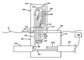
- FIG. 3is a schematic diagram of an example FDH mounted over an example handhole in accordance with aspects of the present disclosure
- FIGS. 4-6show an example handhole in accordance with aspects of the present disclosure
- FIGS. 7 and 8show a first example implementation of an optical cable suitable for use as a feeder cable and/or a subscriber stub cable described herein;
- FIG. 9shows one example implementation of a second cable segment suitable for use as a feeder cable or a subscriber stub cable described herein.
- FIG. 10shows an example plug connector and an example receptacle connector that are configured to interface together in accordance with aspects of the disclosure
- FIGS. 11 and 12show the ferrules of the plug and receptacle multi-fiber connectors of FIG. 10 ;
- FIGS. 13 and 14show an example FDH including a moveable frame shown in an open position in accordance with aspects of the present disclosure
- FIG. 15is a front perspective view of an example manager suitable for retaining the connectorized ends of stub cables within a handhole in accordance with aspects of the present disclosure
- FIG. 16is a rear perspective view of the example manager of FIG. 15 ;
- FIGS. 17-23show various views of one implementation of a housing of an example holder suitable for use with the manager of FIGS. 15 and 16 ;
- FIG. 24shows a boot of a stub cable positioned in a channel of a housing part of the example holder of FIGS. 17-23 in accordance with aspects of the disclosure.
- FIG. 25shows an example holder encircling a boot of a stub cable, the holder being configured to latch to the manager of FIGS. 15 and 16 in accordance with aspects of the disclosure.
- a fiber distribution hubgenerally administers connections between incoming fiber and outgoing fiber in an Outside Plant (OSP) environment.
- the FDHincludes a termination region at which incoming fibers can communicatively connect to the outgoing fibers. In other embodiments, some incoming fibers can connect directly to the outgoing fibers without passing through the termination region. Implementations of the FDH also can provide storage regions, splitter regions, and/or splice regions, each of which will be described in greater detail herein.
- a connectionbetween fibers may include direct connections and/or indirect connections.
- incoming fibersinclude feeder cable fibers, which enter the FDH, and intermediate fibers (e.g., connectorized pigtails extending from splitters and patching fibers/jumpers) that connect the feeder cable fibers to the termination region.
- intermediate fiberse.g., connectorized pigtails extending from splitters and patching fibers/jumpers
- outgoing fibersinclude distribution cable fibers, which exit the FDH, and any intermediate fibers that connect the distribution cable fibers to the termination region.
- the FDHprovides an interconnect interface for optical transmission signals at a location in the network where operational access and reconfiguration are desired.
- the FDHcan be used to split feeder cables and to terminate the split feeder cables to distribution cables routed to subscriber locations.
- the FDHcan provide a splice interface to couple feeder cables to the distribution cables directly.
- the FDHalso can provide storage of incoming fibers before connection to the outgoing cable fibers.
- An example feeder cablemay include one to forty-eight individual fibers.
- the feeder cablecan include two, eight, twelve, twenty-four, and forty-eight fibers.
- the feeder cable 301is connected to a service provider central office 110 (e.g., forms the F 1 portion of the network 100 ) (see FIG. 1 ).
- Example distribution cablesinclude multiple fibers (e.g., 12, 48, 96, 144, 216, 288, 432, or 576 fibers) and form the F 2 portion of a network (see FIG. 1 ).
- the distribution cablesare routed from the FDH to subscriber locations or to other locations within the network 100 .
- the FDHcan be designed to accommodate a range of alternative sizes and fiber counts and to support factory installation of pigtails, fanouts, and optical splitters.
- the FDH 200includes an enclosure (e.g., a cabinet, a frame, etc.) 202 configured to support telecommunications components.
- an example enclosure 202can accommodate one or more splitter modules 800 , one or more termination modules 700 , and one or more storage modules 600 .
- the enclosure 202is mounted on an access module 215 that is mounted to a support panel or platform, which will be described in more detail herein.
- At least one feeder cable 301 and at least one subscriber cables 308can be routed through the access module 215 and into the enclosure 202 through a cable port 210 defined in the enclosure 202 (e.g., typically through the back or bottom of the enclosure).
- at least two subscriber cables 308are routed into the enclosure 202 (e.g., see FIG. 3 ).
- four, eight, twelve, sixteen, or twenty-four, thirty-six, forty-eight, or other number of subscriber cables 308can be routed into the enclosure 202 .
- the cables 301 , 308are secured to the enclosure 202 at the cable port 210 by a cable clamp 310 .
- One or more fibers 302 of the feeder cable 301can be routed from the cable port 210 to a first fiber interface 220 positioned within the enclosure 202 .
- the first fiber interface 220includes one or more fanout modules 217 . Fibers 302 of the feeder cable 301 are separated out into individual fibers at the fanout module 217 .
- the fibers 302are upjacketed (e.g., into buffer tubes) or otherwise protected at the fanout modules 217 . In such embodiments, the fibers 302 have connectorized ends that are routed to a splitter region 230 .
- the first fiber interface 220can include one or more splice trays, adapters, or adapter modules at which the fibers 302 can be optically coupled to splitter input fibers (not shown), which are routed to the splitter region 230 .
- the fibers 302are connected to separate splitter modules 800 , at which signals carried over the fibers 302 are each split into multiple signals carried over connectorized splitter pigtails 303 , 304 .
- a typical splitter pigtail 303 , 304includes a coated (and possibly buffered) fiber, a jacket covering the fiber, and strength members (e.g., aramid yarn) positioned between the fiber and the jacket.
- reference number 303denotes splitter pigtails that are not in service and reference number 304 denotes splitter pigtails that are in service.
- the connectorized ends 305 of the splitter pigtails 303can be temporarily stored on a storage region 250 .
- the connectorized ends 305 of the splitter pigtails 303can be held at storage modules 900 positioned at the storage region 250 .
- the pigtails 304are routed from the splitter region 230 to a termination field 240 .
- the connectorized ends 305 of the splitter pigtails 304can be plugged into termination modules 800 .
- the splitter region 230is positioned so that the splitter pigtails 303 , 304 are routed along a vertical channel C between the splitter region 230 and the termination field 240 or storage region 250 .
- the vertical channel Cis defined by one or more retaining members 270 .
- the retaining members 270include two members that cooperate to wrap around the splitter pigtails 303 , 304 . For example, ends of the two members can fasten together via VELCRO®, a snap-fit engagement, or via another securement arrangement.
- One or more fibers 307 of the subscriber cable 308are routed from the cable port 210 to a second fiber interface 260 positioned within the enclosure 202 .
- the second fiber interface 260includes one or more fanout modules 217 . Fibers 307 of the subscriber cable 308 are separated out into individual fibers at the fanout module 217 .
- the fibers 307are upjacketed (e.g., into buffer tubes) or otherwise protected at the fanout modules 217 .
- the fibers 307have connectorized ends 306 that are routed to a termination region 240 .
- the second fiber interface 260can include one or more splice trays, adapters, or adapter modules at which the fibers 307 can be optically coupled to intermediate fibers (not shown), which are routed to the termination region 240 .
- the termination region 240is the dividing line between the incoming fibers and the outgoing fibers of the FDH 200 .
- the connectorized ends 305 of the splitter pigtails 304are connected to connectorized ends 306 of the fibers 307 of the subscriber cable 308 at the termination field 240 .
- the connectorized ends 305 of the splitter pigtails 304are connected to connectorized ends of intermediate fibers (not shown) that optically couple to the fibers 307 of the subscriber cable 308 .
- the intermediate fibersmay be spliced to fibers 307 of the subscriber cable 308 .
- one or more fibers 302 of the feeder cable 301are not optically coupled to the splitter modules 800 .
- one or more of the feeder fibers 302can be routed directly to the termination field 240 to optically connect to the subscriber fibers 307 (or intermediate fibers).
- the feeder cable fibers 302can be routed to the same side of the termination field 240 as the splitter pigtails 303 . By refraining from splitting the signal carried by the fiber 302 , a stronger signal can be sent to one of the subscribers 115 ( FIG. 1 ).
- the enclosure 202defines an interior in which a frame 204 is mounted.
- the frame 204is moveably (e.g., pivotally) mounted to the enclosure 202 to enable the frame 230 to move relative to the enclosure 202 .
- one or more of the telecommunications componentscan be mounted to the frame 204 .
- the splitter region 230 , the termination region 240 , and the storage region 250can be mounted to the frame 204 .
- one or both of the interface regions 210 , 260can be mounted to the frame 204 .
- one or more of the telecommunications componentscan be mounted to a main body 203 of the enclosure 202 instead of to the frame 204 .
- moveable inner framescan be found in U.S. Pat. No. 7,369,741, issued to Reagan et al. and titled Storage Adapter with Dust Cap Post, the disclosure of which is hereby incorporated by reference herein.
- FIG. 3is a schematic drawing of an example FDH 200 mounted over an example handhole 400 positioned in the ground G beneath the FDH 200 .
- the handhole 400includes a container structure 410 that is buried below ground G and into which at least one conduit 430 is routed.
- the conduits 430are configured to route telecommunications cables 320 of the telecommunications network 100 to different locations in the network.
- a single conduit 430passes through the handhole container 410 .
- multiple conduits 430can pass through the handhole container 410 .
- At least one of the conduits 430provides an access point at which one or more cables 320 can be routed from the conduit 430 to the FDH 200 .
- multiple conduits 430terminate at the container interior.
- the handhole 400includes at least one support panel or platform 412 on which the FDH 200 can be mounted.
- the access module 215can be secured to the support platform 412 and the FDH enclosure 202 can be mounted to the access module 215 .
- the support platform 412is mounted to a top of the container 410 , e.g., as described in more detail herein.
- the panel 412defines a cable port 413 through which the feeder cable(s) 301 and the subscriber cable(s) 308 pass from the handhole container 410 into the enclosure 202 .
- the cable port 413 of the handhole panel 412aligns with the cable port 210 of the enclosure 202 .
- the feeder cable 301 and the subscriber cables 308are stubs cables that are precabled within the enclosure 202 prior to deployment of the FDH 200 .
- the connectorized ends 306 of the fibers 307 of the subscriber cables 309can be plugged into adapters at the termination field 240 within the enclosure at a factory or other manufacturing site.
- the feeder cable fibers 302also can be routed to the splitter region 230 or to the first interface region 220 at the factory.
- the other ends (also referred to as “stub ends”) of the cables 301 , 308extend out from the enclosure 202 through the cable port 210 .
- the stub endscan extend about five to ten feet out from the enclosure 202 .
- the stub cables 301 , 308can be longer or shorter.
- the stub ends of the cables 301 , 308are routed into the handhole container 410 through the cable port 413 .
- the feeder cable 301 and the subscriber cables 308can be optically coupled to one or more of the cables 320 being routed through the conduits 430 .
- stub ends 309 of the subscriber cables 308are connectorized.
- the stub end 309 of at least one subscriber cable 308can be terminated with a multi-fiber connector (MFC) 500 , which is described in more detail below.
- MFCmulti-fiber connector
- at least one cable 320 A being routed through the conduit 430also is terminated with an MFC.
- the MFC 500 of the subscriber stub cable 308can be interfaced (e.g., directly or through an adapter) with the MFC of the cable 320 A to connect the subscriber stub cable 308 to subsequent points in the network 100 (drop terminals 104 , other fiber distribution hubs 130 , subscriber locations 115 , etc.).
- each fiber 307 of the subscriber cable 308is connectorized at both ends to facilitate connection to connectorized fibers within the cables 320 passing through the conduits 430 .
- one or more of the feeder stub cables 301has a connectorized end routed into the interior of the handhole container 410 .
- one or more of the feeder stub cables 301can be terminated with an MFC 500 , which is described in more detail below.
- at least one cable 320 being routed through the conduit 430also is terminated with an MFC.
- the MFC 500 of the feeder stub cable 301can be interfaced (e.g., directly or through an adapter) with the MFC of the cable to connect the feeder stub cable 301 to prior points in the network 100 (central office 110 , other fiber distribution hubs 130 , etc.).
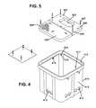
- FIG. 4is a top, perspective view of an example handhole container 410 having an open top 413 leading to an interior 411 .
- Through holes 412are defined within the side walls 416 of the container 410 .
- the through holes 412are sized and shaped to enable conduits 430 to enter and exit the container interior 411 .
- at least one side wall 416defines two through holes 412 and at least one side wall 416 defines four through holes 412 .
- opposing side walls 416can define a like number of through holes 412 to enable conduits 430 to pass fully through the container 410 .
- opposing side walls 416can each define a different number of through holes 412 (including zero).
- the container 410defines shoulders 414 within the interior 411 just below the open top 413 .
- the shoulders 414are provided at the corners of the container 410 . In other example implementations, however, the shoulders 414 also can be provided along the sides of the container 410 .
- the support platform 422is configured to seat on the shoulders 414 at the open top 413 of the container 410 . Brackets 415 or other supporting hardware can be provided on the container 410 for securing the support platform 422 to the container 410 .
- the support panel 422defines a cable port 423 that provides access to the interior 411 of the container 410 .
- the support panel 422also defines through openings 426 through which fasteners (e.g., screws, bolts, rivets, etc.) 427 can extend to secure the support panel 422 to the brackets 415 within the container 410 .
- the support platform 422extends over only a portion of the open top 413 of the container 410 . Accordingly, one or more brackets 415 can be positioned along the sides of the open top 413 of the container 410 (see FIG. 4 ).
- the handhole 400also includes one or more access panels 425 that cover the remainder of the open top 413 to provide selective access to the interior 411 of the container 410 .
- the access panel 425is configured to seat on the support members 414 at the open top 413 of the container 410 .
- the support platform 422includes a step 414 protruding outwardly to provide further support for the access panel 425 (see FIG. 6 ).
- the access panel 425also defines at least one through opening 426 through which a fastener can extend to secure the access panel 425 to the top 413 of the container 410 .
- the fastener that secures the access panel 425 to the container 410is removable. Accordingly, the access panel 425 can be moved to enable a technician to access the interior 411 of the container 410 .
- the access panel 425is configured to be lifted up and fully removed from the open top 413 of the container 410 when access to the container interior 411 is desired.
- the access panel 425is configured to be pivoted upwards to provide access to the container interior 411 .
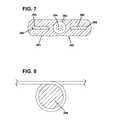
- FIGS. 7 and 8show a first example implementation of an optical cable 380 suitable for use as a feeder cable 300 and/or a subscriber stub cable 308 described herein.
- the first example cable 380includes an outer jacket 381 defining at least a first passage 382 for containing at least one optical fiber 384 and at least a second passage 385 for containing at least one strength member 386 .
- the outer jacket 381includes a central passage 382 for containing optical fibers 384 and two passages 385 on opposite sides of the central passage 384 for containing strength members 386 .
- the first example cable 380can include greater or fewer strength members 386 enclosed within the jacket 381 .
- the first example cable 380has an elongated transverse cross-sectional profile (e.g., a flattened cross-sectional profile, an oblong cross-sectional profile, an obround cross-sectional profile, etc.) defined by the outer jacket 381 .
- the major axis and the minor axis of the cross-sectional profileintersect perpendicularly at a lengthwise axis of the cable 380 .
- the construction of the first example cable 380allows the cable 380 to be bent more easily along a plane that coincides with the minor axis than along a plane that coincides with the major axis.
- Such a constructionallows the first example cable 380 to be readily used for applications in which drop cables are normally used and also allows the first example cable 380 to be wrapped around a cable storage spool having a relatively small diameter without damaging the example cable 380 .
- Other implementations of the first example cable 380can have round, oval, or other transverse cross-sectional profiles, however.
- the outer jacket 381can be shaped through an extrusion process and can be made by any number of different types of polymeric materials.
- the outer jacket 381can have a construction the resists post-extrusion shrinkage of the outer jacket 381 .
- the outer jacket 381can include a shrinkage reduction material disposed within a polymeric base material (e.g., polyethylene).
- a polymeric base materiale.g., polyethylene
- U.S. Pat. No. 7,379,642which is hereby incorporated by reference in its entirety, describes an exemplary use of shrinkage reduction material within the base material of a fiber optic cable jacket 381 .
- the first passage 382 of the outer jacket 381is sized to receive one or more of the bend insensitive fibers 384 .
- the bend insensitive fibers 384are preferably unbuffered and in certain embodiments have outer diameters in the range of 230-270 ⁇ m.
- the first passage 382is sized to receive at least twelve of the bend insensitive fibers 384 . When the fibers 384 are positioned within the first passage 382 , it is preferred for the fibers 384 to occupy less than 60% of the total transverse cross-sectional area defined by the first passage 382 .
- structuressuch water-swellable fibers, water-swellable tape, or water-swellable yarn can be provided within the passage 382 to prevent water from migrating along the first passage 382 .
- water-blocking gelmay be provided within the first passage 382 .
- the strength members 386 of the first example cable 380have a transverse cross-sectional profile that matches the transverse cross-sectional profile of the second passage 385 .
- each strength members 386has a width that is greater than a thickness of the strength member 386 .
- the strength members 386are bonded to the outer jacket 381 .
- the bonding between the strength members 386 and the outer jacket 381can be chemical bonding or thermal bonding.
- each strength members 386has a construction that is highly flexible and highly strong in tension.
- the strength members 386provide the vast majority of the tensile load capacity of the first example cable 380 .
- each strength member 386also has a flexibility that allows the strength member 386 to be wrapped at least 360 degrees around a mandrel 389 (see FIG. 8 ) having a 10 millimeter outer diameter for one hour without undergoing/experiencing meaningful deterioration/degradation of the tensile strength properties of the strength member 386 .
- the strength member 386is formed by a generally flat layer of reinforcing elements (e.g., fibers or yarns such as aramid fibers or yarns) embedded or otherwise integrated within a binder to form a flat reinforcing structure (e.g., a structure such as a sheet-like structure, a film-like structure, or a tape-like structure).
- the binderis a polymeric material such ethylene acetate acrylite (e.g., UV-cured, etc.), silicon (e.g., RTV, etc.), polyester films (e.g., biaxially oriented polyethylene terephthalate polyester film, etc.), and polyisobutylene.
- the bindermay be a matrix material, an adhesive material, a finish material, or another type of material that binds, couples or otherwise mechanically links together reinforcing elements.
- the strength member 386can have a glass reinforced polymer (GRP) construction.
- the glass reinforced polymercan include a polymer base material reinforced by a plurality of glass fibers such as E-glass, S-glass or other types of glass fiber.
- the polymer used in the glass reinforced polymeris preferably relatively soft and flexible after curing.
- the polymerhas a Shore A hardness less than 50 after curing.
- the polymerhas a Shore A hardness less than 46 after curing.
- the polymerhas a Shore A hardness in the range of about 34-46.
- first cable segment 110Additional details regarding the example first cable segment 110 can be found in U.S. application Ser. No. 12/607,748, filed Oct. 28, 2009, published as US 2010/0278493, and titled “Flat Drop Cable,” the disclosure of which is hereby incorporated herein by reference in its entirety.
- other types of fiber optic cables having different tensile strength and flexibility characteristicscan be used as the first cable segment.
- FIG. 9shows one example implementation of a second cable segment 390 suitable for use as a feeder cable 300 or a subscriber stub cable 308 described herein.
- the second example cable 390includes a cable jacket 391 enclosing at least one optical fiber 392 .
- the optical fiber 392is loosely received within a buffer tube 393 .
- buffer tube 393includes at least one waterblocking substance, for example, a gel, grease, and/or a superabsorbent material.
- the second example cable 390has a generally flat configuration.
- the jacket 391can define generally arcuate sections 395 and generally flat-sided sections 396 .
- Other implementations of the second example cable 390can have round, oval, or other transverse cross-sectional profiles.
- the second example cable 390also includes at least one strength component 397 .
- the optical transmission component 392is disposed between two strength components 397 .
- greater or fewer strength components 397can be used.
- the strength components 397have both tensile and anti-buckling characteristics.
- the strength components 397are solid, rod-like members formed of dielectric materials.
- a strength component 397includes glass filaments impregnated and bonded together with a resin to define a single unit having a tensile strength rating of about 500 Newtons @0.5% strain.
- the second example cable 390can include one or more tensile strength members 398 (e.g., a group of fiberglass strands). In other implementations, however, the strength components 397 provide the tensile strength of the second example cable 390 . Additional details regarding the example second example cable 390 can be found in U.S. Pat. No. 6,542,674, titled “Fiber Optic Cables with Strength Members,” and issued Apr. 1, 2003 to Corning Cable Systems, LLC, the disclosure of which is hereby incorporated by reference herein. Of course, other types of fiber optic cables having different tensile strength and flexibility characteristics can be used as the second cable segment.
- FIGS. 10-12provide example connectors suitable for terminating the stub ends 309 of the subscriber cables 308 , the feeder cables 300 , and/or the ends of the cables 320 passing through the conduits 430 .
- the interface end of a first example connector 500is shown in FIG. 11 and the interface end of a second example connector 500 ′ is shown in FIG. 12 .
- the first example connector 500is sized and shaped to couple to the second example connector 500 ′ without an adapter.
- the first example connector 500can define a plug and the second example connector 500 ′ can define a receptacle that is configured to receive the plug 500 .
- FIG. 10shows the plug 500 disengaged from the receptacle 500 ′.
- a threaded coupling nut 550 on the plug 500is operable for securing the plug 500 to the receptacle 500 ′ upon engagement.
- the connector plug 500includes a ferrule 510 at which one or more optical fibers 511 are terminated.
- the connector receptacle 500 ′also includes a ferrule 510 ′ at which one or more optical fibers 511 ′ are terminated.
- the plug 500 and receptacle 500 ′are operable for aligning and maintaining the optical fibers of each in opposing relation for transmitting an optical signal.
- the plug 500 and the receptacle 500 ′may be threadably coupled together.
- both the subscriber cables 308 and the conduit cables 320can be terminated with the same type of connector 500 , 500 ′ and can be interfaced at an adapter.
- the plug ferrule 510terminates multiple (e.g., two, eight, twelve, sixteen, twenty-four, forty-eight, seventy-two, etc.) optical fibers 511 .
- the ferrule 510terminates twelve optical fibers 511 .
- the plug ferrule 510defines keying openings 512 at either side of the optical fibers 511 .
- the ferrule 510is enclosed within a shroud 514 that defines keying and latching features.
- the shroud 514 and ferrule 510extend forwardly of a connector base 515 .
- the shroud 514extends beyond the ferrule 510 .
- the shroud 514defines a first keying channel 520 and a second keying channel 522 above and below the ferrule 510 , respectively.
- Strength members of the cablese.g., feeder stub cable 300 and subscriber stub cable 308
- strength members of the cablesmay be anchored to the connector plug 500 .
- strength members of the cablesmay be crimped to a portion of the connector plug 500 .
- the receptacle ferrule 510 ′terminates multiple (e.g., two, eight, twelve, sixteen, twenty-four, forty-eight, seventy-two, etc.) optical fibers 511 . In the example shown, the receptacle ferrule 510 ′ terminates twelve optical fibers 511 ′.
- the receptacle ferrule 510 ′is enclosed within a connector body 515 ′ defines a cavity 514 ′ that is sized and shaped to receive the shroud 514 of the plug 500 .
- the connector base 515 ′is configured to surround the shroud 514 . In some embodiments, the connector base 515 ′ latches, screws, or otherwise secures to the shroud 514 to retain the plug 500 and the receptacle 500 ′ in a mated configuration.
- the receptacle ferrule 510 ′defines keying projections 512 ′ at either side of the optical fibers 511 ′.
- the projections 512 ′are configured to be inserted into the keying openings 512 of the plug ferrule 510 to facilitate alignment of the ferrules 510 , 510 ′.
- a first keying projection 520 ′ and a second keying projection 522 ′are positioned within the cavity 514 ′ above and below the ferrule 510 ′, respectively.
- the first and second keying projections 520 ′, 522 ′have different shapes and/or sizes to facilitate finding the correct orientation of the plug and receptacle.
- Strength members of the cablesalso may be anchored to the connector receptacle 500 ′.
- strength members of the cablesmay be crimped to a portion of the connector receptacle 500 ′.
- the connectors 500 , 500 ′include an environmental seal when interfaced together to protect the ferrules 511 , 511 ′ from dust, dirt, or other contaminants.
- environmental sealing structurescan be mounted to the connectors 500 , 500 ′ to protect the ferrules 511 , 511 ′ prior to deployment of the FDH 200 or prior to connection of the connectors 500 , 500 ′.
- a protective pulling cap 530is shown exploded from the plug 500 in FIG. 10 .
- the pulling cap 530defines a threaded portion 532 at its rearward end and a pulling loop 534 at its forward end.
- the pulling cap 530provides protection of the optical connector of the plug 500 during shipping and deployment, and until engagement of the plug 500 with the receptacle 500 ′.
- the pulling cap 530may be secured to the cable using a tether 536 so that the pulling cap 530 may be reused if the plug 500 is later disengaged from the receptacle 500 ′.
- the coupling nut 550also may secure the pulling cap 530 to the plug 500 during shipping and deployment of the corresponding cable.
- a protective dust cap 540is shown exploded from the receptacle 500 ′ in FIG. 10 .
- the receptacle 500 ′may be covered and sealed with a threaded protective dust cap 540 during shipping and deployment.
- the dust cap 540is removed prior to inserting the plug 500 into the receptacle 500 ′.
- the dust cap 540may be secured to the receptacle 500 ′ using a tether 546 .
- a pre-formed, elastomeric seal boot(not shown) may provide protection for the receptacle 500 ′ from the environment within the connection terminal.
- the protective bootalso may provide a sealing function.
- the protective bootallows the assembly to be installed in a breathable connection terminal or similar enclosure, and may be unnecessary in the event the receptacle 500 ′ is otherwise reliably sealed from the environment.
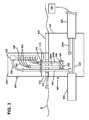
- FIGS. 13 and 14show an example FDH 200 including an example enclosure 202 having a main body 203 and movable frame 204 .
- a splitter region 230 , termination region 240 , and storage region 250are located on the frame 204 .
- the frame 204is shown in an open position to provide access to a back of the enclosure 202 .
- An access panel 211is shown covering the cable access port 210 .
- the enclosure 202is shown mounted on the access module 215 .
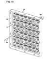
- Example distribution cables 308are shown exiting the access module 215 .
- the stub end 309 of each distribution cable 308is terminated at a connector (e.g., a multi-fiber connector 500 ).
- a connectore.g., a multi-fiber connector 500
- twenty-four distribution cables 308are extending outwardly from the access module 215 .
- the distribution cables 308are shown grouped into six rows that extend four connectors 500 deep.
- the distribution cables 308are routed through the cable port 423 in the support platform 422 shown in FIG. 14 .
- the termination region 240includes a panel or bulkhead at which one or more termination modules 700 can be mounted.
- the termination region 240includes one or more termination panels, each of which defines openings into which termination modules 700 may be inserted.
- the termination panelsmay be incrementally added as the number of subscribers increases.
- each termination module 700includes an adapter 710 (e.g., see FIG. 12 ). Each end of each adapter 710 is configured to receive a connectorized end of an optical fiber. For example, one end of an adapter 710 may receive the connectorized ends 305 of a splitter pigtail 304 and the opposite end of the adapter 710 may receive a connectorized end 306 of a subscriber fiber 307 , thereby coupling the feeder cable 301 to the subscriber cable 308 . As noted above, the termination modules 700 can be precabled at the factory to include the connectorized ends 306 of the subscriber fibers 307 plugged into the second ends of the adapters 710 . Dust caps may be provided on the first ends of the adapters 710 to protect the connectorized ends 306 of the subscriber fibers 307 from dust, dirt, and other contaminants.
- each opening 242 in the termination region 240is configured to receive a single horizontal row of twelve adapters 710 . In other embodiments, however, each opening 242 in the termination region 250 may be configured to receive greater or fewer numbers of adapters 710 .
- each termination module 700includes a housing defining multiple adapters 710 as a single unit. One example of such a termination module is found in FIGS. 8-10 and the accompanying text of U.S. Pat. No. 7,623,749 to Reagan et al., issued Nov. 24, 2009, and titled “Fiber Distribution Hub with Modular Termination Blocks,” the disclosure of which is incorporated herein by reference. In other embodiments, however, each termination module 700 includes only a single adapter 710 .
- One example storage modules 600can be found in U.S. Pat. No. 7,198,409 to Smith et al., issued Apr. 3, 2007, and titled “Fiber Optic Connector Holder and Method;” U.S. Pat. No. 7,233,731 to Solheid et al., issued Jun. 19, 2007, and titled “Telecommunications Connection Cabinet;” and U.S. Pat. No. 7,218,827 to Vongseng et al., issued May 15, 2007, and titled “Multi-position Fiber Optic Connector Holder and Method,” the disclosures of which are hereby incorporated herein by reference.
- splitter module 800is described in U.S. Pat. No. 7,418,181 to Zimmel et al., issued Aug. 26, 2008, and titled “Fiber Optic Splitter Module,” which is hereby incorporated by reference herein.
- the connectorized ends 309 of the subscriber cables 308can be organized in a manager 330 while positioned in the handhole 400 .
- the manager 330may releasably retain the connectorized ends 309 before the connectorized end are connected to cables 320 within the handhole 400 .
- a usermay access the handhole 400 , release at least one of the connectorized ends 309 from the manager 330 located within the handhole 400 , and connect the released connectorized end 309 to one of the network cables 320 .
- the manager 330includes a body that is configured to retain each of the MFC connectors 500 of the subscriber cables 308 . In other implementations, the manger 330 includes a body that is configured to retain each of the subscriber stub cables 308 at a point adjacent the connectors 500 . In one implementation, the manager 330 includes a panel from which fingers project to retain the connectors 500 or the cables 308 . In another implementation, the manager 330 includes a housing defining receptacles configured to receive the connectors 500 .
- the manager 330includes a panel 331 configured to hold one or more connectorized ends 309 of the stub cables.
- the panel 331is configured to be mounted within the handhole 400 .
- the panel 331includes mounting members 332 defining openings 333 through which one or more fasteners may extend to the secure the panel 331 within the handhole 400 .
- the mounting members 332extend generally perpendicular to the panel 331 so that the manager 330 has a generally U-shaped cross-section.
- One or more connector holders 335are coupled to the panel 331 .
- the panel 331defines one or more openings 334 at which the holders 335 mount to the panel 331 .
- multiple holders 335are positioned at each opening 334 .
- only one holder 335is positioned at each opening 334 .
- At least a portion of each holder 335may extend through the openings 334 .
- the entire holder 335extends through the opening 334 .
- each holder 335defines a latching arrangement 337 that secures the holder 335 to the panel 331 . In certain implementations, only the latching arrangement 337 extends through the opening 334 .
- Each holder 335is configured to retain the connectorized end 309 of one or more stub cables located in the handhole 400 .
- each holder 335may define one or more openings 338 through which a portion of a stub cable (cable 308 , cable 300 , etc.) or the corresponding connector 500 , 500 ′ may extend.
- each holder 335defines a single opening 338 through which a stub cable may extend.
- each holder 335may define a plurality of openings 338 , each holding a stub cable.
- each holder 335encircles or otherwise attaches to the connector 500 , 500 ′ terminating the stub ending 309 .
- each holder 335encircles or otherwise attaches to the outer jacket of the stub cable. In certain implementations, each holder 335 encircles or otherwise attaches to the boot 311 or other portion of the stub cable 308 (see FIGS. 24-25 ).
- each holder 335is formed from two housing parts that cooperate to define a passage 338 through which a stub cable may extend.
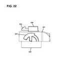
- FIGS. 17-23illustrate one example implementation of a suitable housing 340 for a holder 335 .
- the holder 335is formed by attaching two identical housings 340 together.
- each housing 340may include a body 341 defining a channel 342 sized and shaped to accommodate a portion of the connectorized end 309 of a stub cable. When the housings 340 are coupled together, the channels 342 are aligned to form the through-passage 338 of the holder 335 .
- fixing members 349are positioned in the channels 342 to aid in securing the stub cable within the holder 335 .
- the fixing members 349may be configured to fit with notches or other features defined in the cable.
- the fixing members 349inhibit the stub cable from being axially pulled through out of the holder 335 .
- the fixing members 349inhibit rotation of the stub cable within the holder 335 .
- the housing body 341defines a channel 342 configured to accommodate a boot 311 of the stub cable 308 .
- the boot 311extends from a rounded portion to a partially flattened portion.
- the channels 342are configured to define a rounded port at one end of the holder and an obround port at an opposite end of the holder.
- Each housing body 341also includes a latching arrangement 337 that secures the holder 335 to the manager panel 331 .
- the latching arrangement 337 of each housing body 341includes a latching tab 343 and at least one lug 344 .
- each latching tab 343resiliently extends from an exterior surface of the housing body 341 .
- a lug 344is positioned on either side of the second tab 343 .
- each housing body 341includes at least one attachment tab 345 at one side and at least a first opening 346 at an opposite side.
- the first attachment tab 345 of the each housing body 341cooperates with the first opening 346 of the other housing body 341 to lock the housing bodies 341 together.
- the first attachment tab 345defines a notch that accommodates a wall between adjacent openings 346 in the housing body 341 .
- each holder 335is configured to attach to one or more adjacent holders 335 .
- multiple holders 335attach together without a panel 331 or other manager.
- first and second side members 347 , 348extend outwardly from opposite sides of the housing body 341 .
- the first and second side members 347 , 348are configured to cooperate to define an attachment arrangement that fits with an identical attachment arrangement on an adjacent holder 335 .
Landscapes
- Physics & Mathematics (AREA)
- General Physics & Mathematics (AREA)
- Optics & Photonics (AREA)
- Light Guides In General And Applications Therefor (AREA)
- Mechanical Coupling Of Light Guides (AREA)
Abstract
Description
Claims (16)
Priority Applications (1)
| Application Number | Priority Date | Filing Date | Title |
|---|---|---|---|
| US13/040,053US8649649B2 (en) | 2010-03-03 | 2011-03-03 | Fiber distribution hub with connectorized stub cables |
Applications Claiming Priority (2)
| Application Number | Priority Date | Filing Date | Title |
|---|---|---|---|
| US31021410P | 2010-03-03 | 2010-03-03 | |
| US13/040,053US8649649B2 (en) | 2010-03-03 | 2011-03-03 | Fiber distribution hub with connectorized stub cables |
Publications (2)
| Publication Number | Publication Date |
|---|---|
| US20110217015A1 US20110217015A1 (en) | 2011-09-08 |
| US8649649B2true US8649649B2 (en) | 2014-02-11 |
Family
ID=44531409
Family Applications (1)
| Application Number | Title | Priority Date | Filing Date |
|---|---|---|---|
| US13/040,053Active2031-12-08US8649649B2 (en) | 2010-03-03 | 2011-03-03 | Fiber distribution hub with connectorized stub cables |
Country Status (1)
| Country | Link |
|---|---|
| US (1) | US8649649B2 (en) |
Cited By (8)
| Publication number | Priority date | Publication date | Assignee | Title |
|---|---|---|---|---|
| US20120189260A1 (en)* | 2010-12-20 | 2012-07-26 | Adc Telecommunications, Inc. | Fan-Out and Parking Module |
| US20140133806A1 (en)* | 2012-11-14 | 2014-05-15 | John P. Hill | Multiport optical fiber terminal |
| US20150055954A1 (en)* | 2013-08-26 | 2015-02-26 | Adc Telecommunications, Inc. | Wave Division Multiplexer Arrangement for Small Cell Networks |
| US20150334476A1 (en)* | 2010-04-14 | 2015-11-19 | Adc Telecommunications, Inc. | Methods and systems for distributing fiber optic telecommunication services to local areas and for supporting distributed antenna systems |
| US20160178859A1 (en)* | 2014-12-19 | 2016-06-23 | 3M Innovative Properties Company | Ruggedized optical fiber connection structures and assemblies |
| US10935745B1 (en) | 2017-07-20 | 2021-03-02 | Forrest Tyrone Gay | Multi-carrier fiber distribution hub |
| US20230305253A1 (en)* | 2022-03-28 | 2023-09-28 | Corning Research & Development Corporation | Optical distribution system and related methods |
| US12276857B2 (en) | 2019-10-07 | 2025-04-15 | Commscope Technologies Llc | Fiber distribution hub including sealed splice module |
Families Citing this family (4)
| Publication number | Priority date | Publication date | Assignee | Title |
|---|---|---|---|---|
| US9276673B2 (en) | 2008-04-24 | 2016-03-01 | Commscope Technologies Llc | Methods and systems for testing a fiber optic network |
| CN101726802A (en)* | 2008-10-28 | 2010-06-09 | 上海瑞侃电缆附件有限公司 | Optical fiber terminal box |
| AU2016354633A1 (en)* | 2015-11-13 | 2018-04-26 | CommScope Connectivity Belgium BVBA | Fiber optic connection system |
| US11579357B2 (en) | 2018-03-20 | 2023-02-14 | Commscope Technologies Llc | Fiber optic cable terminal with a pushable stub cable |
Citations (72)
| Publication number | Priority date | Publication date | Assignee | Title |
|---|---|---|---|---|
| US4747020A (en) | 1986-05-16 | 1988-05-24 | Adc Telecommunications, Inc. | Wire distribution apparatus |
| US4765710A (en) | 1985-07-30 | 1988-08-23 | Siemens Aktiengesellschaft | Distributing frame for optical waveguides and the like |
| US4792203A (en) | 1985-09-17 | 1988-12-20 | Adc Telecommunications, Inc. | Optical fiber distribution apparatus |
| US4995688A (en) | 1989-07-31 | 1991-02-26 | Adc Telecommunications, Inc. | Optical fiber distribution frame |
| US5100221A (en) | 1990-01-22 | 1992-03-31 | Porta Systems Corp. | Optical fiber cable distribution frame and support |
| US5129030A (en) | 1991-05-30 | 1992-07-07 | At&T Bell Laboratories | Movable lightguide connector panel |
| US5179618A (en) | 1990-07-11 | 1993-01-12 | Adc Telecommunications, Inc. | Fiber optic connector module |
| US5214730A (en) | 1991-05-13 | 1993-05-25 | Nippon Telegraph And Telephone Corporation | Multifiber optical connector plug with low reflection and low insertion loss |
| US5274731A (en) | 1992-12-24 | 1993-12-28 | Adc Telecommunications, Inc. | Optical fiber cabinet |
| US5289558A (en) | 1991-10-05 | 1994-02-22 | Krone Aktiengesellshaft | Switching assembly for glass fiber cables of the telecommunication and data technology |
| US5363465A (en) | 1993-02-19 | 1994-11-08 | Adc Telecommunications, Inc. | Fiber optic connector module |
| US5367598A (en) | 1993-10-21 | 1994-11-22 | Nec America, Inc. | Interface chassis for fiber optic transport system |
| US5442726A (en) | 1994-02-22 | 1995-08-15 | Hubbell Incorporated | Optical fiber storage system |
| US5448015A (en) | 1991-12-30 | 1995-09-05 | Societe Anonyme Dite Alcatel Cit | Support and Guide device for cables carrying elcetrical or light signals |
| US5497444A (en) | 1994-01-21 | 1996-03-05 | Adc Telecommunications, Inc. | High-density fiber distribution frame |
| US5511144A (en) | 1994-06-13 | 1996-04-23 | Siecor Corporation | Optical distribution frame |
| US5636138A (en) | 1992-12-29 | 1997-06-03 | Lucent Technologies Inc. | Jumper cable selection and routing system |
| US5708751A (en) | 1996-04-24 | 1998-01-13 | Tii Industries, Inc. | Optical fiber enclosure system |
| US5784515A (en) | 1995-01-23 | 1998-07-21 | Nippon Telegraph And Telephone Corporation | Optical fiber cross connection apparatus and method |
| US5823646A (en) | 1997-09-02 | 1998-10-20 | Siecor Corporation | Door assembly for optical hardware cabinet |
| US5945633A (en) | 1996-05-23 | 1999-08-31 | The Siemon Company | Rack mountable cable distribution enclosure having an angled adapter plate bracket |
| US6044193A (en) | 1998-07-10 | 2000-03-28 | Siecor Operations, Llc | Fiber optic interconnection enclosure having a forced air system |
| US6061492A (en) | 1997-04-09 | 2000-05-09 | Siecor Corporation | Apparatus and method for interconnecting fiber cables |
| US6160946A (en) | 1998-07-27 | 2000-12-12 | Adc Telecommunications, Inc. | Outside plant fiber distribution apparatus and method |
| US6208796B1 (en) | 1998-07-21 | 2001-03-27 | Adc Telecommunications, Inc. | Fiber optic module |
| US6236795B1 (en) | 1999-06-07 | 2001-05-22 | E. Walter Rodgers | High-density fiber optic cable distribution frame |
| US6256443B1 (en) | 1998-07-24 | 2001-07-03 | Nippon Telegraph And Telephone Corporation | Optical fiber distribution module for holding an optical fiber cord and fiber distribution system using optical fiber cords |
| US6278829B1 (en) | 1999-05-05 | 2001-08-21 | Marconi Communications, Inc. | Optical fiber routing and support apparatus |
| US6356697B1 (en) | 1999-05-04 | 2002-03-12 | Sumitomo Electric Lightwave Corp. | Optical fiber cable distribution shelf with pivotably mounted trays |
| US6385381B1 (en) | 1999-09-21 | 2002-05-07 | Lucent Technologies Inc. | Fiber optic interconnection combination closure |
| US6424781B1 (en) | 1999-03-01 | 2002-07-23 | Adc Telecommunications, Inc. | Optical fiber distribution frame with pivoting connector panels |
| US6434313B1 (en) | 2000-10-31 | 2002-08-13 | Corning Cable Systems Llc | Fiber optic closure with couplers and splice tray |
| US20020150372A1 (en) | 2001-02-12 | 2002-10-17 | Fiber Optic Network Solutions Corp. | Optical fiber enclosure system |
| US6487358B1 (en)* | 2001-07-27 | 2002-11-26 | Ciena Corporation | Blank module with conduit retainer |
| US6535682B1 (en) | 1999-03-01 | 2003-03-18 | Adc Telecommunications, Inc. | Optical fiber distribution frame with connector modules |
| US6556763B1 (en) | 1999-03-01 | 2003-04-29 | Adc Telecommunications, Inc. | Optical fiber distribution frame with connector modules |
| US6621975B2 (en) | 2001-11-30 | 2003-09-16 | Corning Cable Systems Llc | Distribution terminal for network access point |
| US6631237B2 (en) | 2001-03-06 | 2003-10-07 | Adc Telecommunications, Inc. | Termination and splice panel |
| US6661961B1 (en) | 2000-11-01 | 2003-12-09 | Tyco Electronics Corporation | Fiber low profile network interface device |
| US20040014367A1 (en) | 2002-07-19 | 2004-01-22 | Petersen Cyle D. | Telecommunications connector adapted for bi-directional insertion |
| US6760530B1 (en) | 2000-06-09 | 2004-07-06 | Cisco Technology, Inc. | Fiber cable connector clip |
| US6760531B1 (en) | 1999-03-01 | 2004-07-06 | Adc Telecommunications, Inc. | Optical fiber distribution frame with outside plant enclosure |
| US6778752B2 (en) | 2002-05-31 | 2004-08-17 | Corning Cable Systems Llc | Below grade closure for local convergence point |
| US6788786B1 (en) | 2000-09-22 | 2004-09-07 | Adc Telecommunications, Inc. | Multimedia patching box |
| US6792190B2 (en) | 2001-06-01 | 2004-09-14 | Telect, Inc. | High density fiber optic splitter/connector tray system |
| US6792191B1 (en) | 2003-04-22 | 2004-09-14 | Corning Cable Systems Llc | Local convergence cabinet |
| US6850685B2 (en) | 2002-03-27 | 2005-02-01 | Adc Telecommunications, Inc. | Termination panel with pivoting bulkhead and cable management |
| US6853795B2 (en) | 2003-03-05 | 2005-02-08 | Corning Cable Systems Llc | High density fiber optic distribution frame |
| US6870734B2 (en) | 2003-05-30 | 2005-03-22 | Adc Telecommunications, Inc. | Fiber containment system |
| US6909833B2 (en) | 2002-03-15 | 2005-06-21 | Fiber Optic Network Solutions, Inc. | Optical fiber enclosure system using integrated optical connector and coupler assembly |
| US6920274B2 (en) | 2003-12-23 | 2005-07-19 | Adc Telecommunications, Inc. | High density optical fiber distribution frame with modules |
| US6925241B2 (en) | 2002-10-11 | 2005-08-02 | 3M Innovative Properties Company | Drawer for the management of optical fibers |
| US6968111B2 (en) | 2000-01-24 | 2005-11-22 | Adc Telecommunications, Inc. | Cable management panel with sliding drawer |
| US20050259928A1 (en) | 2004-05-24 | 2005-11-24 | Elkins Robert B Ii | Distribution cable assembly having overmolded mid-span access location |
| US6980725B1 (en) | 2002-04-30 | 2005-12-27 | Calix Networks, Inc. | Space reuse during technology upgrade in a protection area of an outdoor enclosure |
| US6983095B2 (en) | 2003-11-17 | 2006-01-03 | Fiber Optic Network Solutions Corporation | Systems and methods for managing optical fibers and components within an enclosure in an optical communications network |
| US7086539B2 (en) | 2002-10-21 | 2006-08-08 | Adc Telecommunications, Inc. | High density panel with rotating tray |
| US7088893B2 (en) | 2003-11-26 | 2006-08-08 | Corning Cable Systems Llc | Pre-connectorized fiber optic distribution cable having multifiber connector |
| US7120347B2 (en) | 2004-01-27 | 2006-10-10 | Corning Cable Systems Llc | Multi-port optical connection terminal |
| US7142764B2 (en) | 2003-03-20 | 2006-11-28 | Tyco Electronics Corporation | Optical fiber interconnect cabinets, termination modules and fiber connectivity management for the same |
| US7198409B2 (en) | 2003-06-30 | 2007-04-03 | Adc Telecommunications, Inc. | Fiber optic connector holder and method |
| US7218827B2 (en) | 2004-06-18 | 2007-05-15 | Adc Telecommunications, Inc. | Multi-position fiber optic connector holder and method |
| US7233731B2 (en) | 2003-07-02 | 2007-06-19 | Adc Telecommunications, Inc. | Telecommunications connection cabinet |
| US7264402B2 (en) | 2005-03-10 | 2007-09-04 | Corning Cable Systems Llc | Multi-fiber optic receptacle and plug assembly |
| US7369741B2 (en) | 2003-11-17 | 2008-05-06 | Fiber Optics Network Solutions Corp. | Storage adapter with dust cap posts |
| US7418181B2 (en) | 2006-02-13 | 2008-08-26 | Adc Telecommunications, Inc. | Fiber optic splitter module |
| US7519258B2 (en) | 2006-12-21 | 2009-04-14 | Corning Cable Systems Llc | Preconnectorized fiber optic local convergence points |
| US7539388B2 (en) | 2004-03-08 | 2009-05-26 | Adc Telecommunications, Inc. | Fiber access terminal |
| US7623749B2 (en) | 2005-08-30 | 2009-11-24 | Adc Telecommunications, Inc. | Fiber distribution hub with modular termination blocks |
| US7693374B2 (en) | 2006-05-11 | 2010-04-06 | Corning Cable Systems Llc | Tools and methods for manufacturing fiber optic distribution cables |
| US20100310226A1 (en)* | 2009-06-03 | 2010-12-09 | Emerson Network Power, Energy Systems, North America, Inc. | Dust Caps for Fiber Optic Connectors |
| US20100322568A1 (en)* | 2009-05-19 | 2010-12-23 | Adc Telecommunications, Inc. | Mechanical interface between a fiber optic cable and a fiber optic connector |
- 2011
- 2011-03-03USUS13/040,053patent/US8649649B2/enactiveActive
Patent Citations (91)
| Publication number | Priority date | Publication date | Assignee | Title |
|---|---|---|---|---|
| US4765710A (en) | 1985-07-30 | 1988-08-23 | Siemens Aktiengesellschaft | Distributing frame for optical waveguides and the like |
| US4792203A (en) | 1985-09-17 | 1988-12-20 | Adc Telecommunications, Inc. | Optical fiber distribution apparatus |
| US4747020A (en) | 1986-05-16 | 1988-05-24 | Adc Telecommunications, Inc. | Wire distribution apparatus |
| US4995688A (en) | 1989-07-31 | 1991-02-26 | Adc Telecommunications, Inc. | Optical fiber distribution frame |
| USRE34955E (en) | 1989-07-31 | 1995-05-30 | Adc Telecommunications, Inc. | Optical fiber distribution frame |
| USRE37489E1 (en) | 1989-07-31 | 2002-01-01 | Adc Telecommunications, Inc. | Optical fiber distribution frame |
| US5100221A (en) | 1990-01-22 | 1992-03-31 | Porta Systems Corp. | Optical fiber cable distribution frame and support |
| US5179618A (en) | 1990-07-11 | 1993-01-12 | Adc Telecommunications, Inc. | Fiber optic connector module |
| US5214730A (en) | 1991-05-13 | 1993-05-25 | Nippon Telegraph And Telephone Corporation | Multifiber optical connector plug with low reflection and low insertion loss |
| US5129030A (en) | 1991-05-30 | 1992-07-07 | At&T Bell Laboratories | Movable lightguide connector panel |
| US5289558A (en) | 1991-10-05 | 1994-02-22 | Krone Aktiengesellshaft | Switching assembly for glass fiber cables of the telecommunication and data technology |
| US5448015A (en) | 1991-12-30 | 1995-09-05 | Societe Anonyme Dite Alcatel Cit | Support and Guide device for cables carrying elcetrical or light signals |
| US5274731A (en) | 1992-12-24 | 1993-12-28 | Adc Telecommunications, Inc. | Optical fiber cabinet |
| US5636138A (en) | 1992-12-29 | 1997-06-03 | Lucent Technologies Inc. | Jumper cable selection and routing system |
| US5363465A (en) | 1993-02-19 | 1994-11-08 | Adc Telecommunications, Inc. | Fiber optic connector module |
| US5367598A (en) | 1993-10-21 | 1994-11-22 | Nec America, Inc. | Interface chassis for fiber optic transport system |
| US5717810A (en) | 1994-01-21 | 1998-02-10 | Adc Telecommunications, Inc. | High-density fiber distribution frame |
| US5497444A (en) | 1994-01-21 | 1996-03-05 | Adc Telecommunications, Inc. | High-density fiber distribution frame |
| US5442726A (en) | 1994-02-22 | 1995-08-15 | Hubbell Incorporated | Optical fiber storage system |
| US5511144A (en) | 1994-06-13 | 1996-04-23 | Siecor Corporation | Optical distribution frame |
| US5784515A (en) | 1995-01-23 | 1998-07-21 | Nippon Telegraph And Telephone Corporation | Optical fiber cross connection apparatus and method |
| US5708751A (en) | 1996-04-24 | 1998-01-13 | Tii Industries, Inc. | Optical fiber enclosure system |
| US5945633A (en) | 1996-05-23 | 1999-08-31 | The Siemon Company | Rack mountable cable distribution enclosure having an angled adapter plate bracket |
| US6061492A (en) | 1997-04-09 | 2000-05-09 | Siecor Corporation | Apparatus and method for interconnecting fiber cables |
| US5823646A (en) | 1997-09-02 | 1998-10-20 | Siecor Corporation | Door assembly for optical hardware cabinet |
| US6044193A (en) | 1998-07-10 | 2000-03-28 | Siecor Operations, Llc | Fiber optic interconnection enclosure having a forced air system |
| US6208796B1 (en) | 1998-07-21 | 2001-03-27 | Adc Telecommunications, Inc. | Fiber optic module |
| US6256443B1 (en) | 1998-07-24 | 2001-07-03 | Nippon Telegraph And Telephone Corporation | Optical fiber distribution module for holding an optical fiber cord and fiber distribution system using optical fiber cords |
| US6363200B1 (en) | 1998-07-27 | 2002-03-26 | Adc Telecommunications, Inc. | Outside plant fiber distribution apparatus and method |
| US6160946A (en) | 1998-07-27 | 2000-12-12 | Adc Telecommunications, Inc. | Outside plant fiber distribution apparatus and method |
| US6424781B1 (en) | 1999-03-01 | 2002-07-23 | Adc Telecommunications, Inc. | Optical fiber distribution frame with pivoting connector panels |
| US6556763B1 (en) | 1999-03-01 | 2003-04-29 | Adc Telecommunications, Inc. | Optical fiber distribution frame with connector modules |
| US6760531B1 (en) | 1999-03-01 | 2004-07-06 | Adc Telecommunications, Inc. | Optical fiber distribution frame with outside plant enclosure |
| US7333707B2 (en) | 1999-03-01 | 2008-02-19 | Adc Telecommunications, Inc. | Optical fiber distribution frame with outside plant enclosure |
| US7149398B2 (en) | 1999-03-01 | 2006-12-12 | Adc Telecommunications, Inc. | Optical fiber distribution frame with outside plant enclosure |
| US7139461B2 (en) | 1999-03-01 | 2006-11-21 | Adc Telecommunications, Inc. | Optical fiber distribution frame with outside plant enclosure |
| US6535682B1 (en) | 1999-03-01 | 2003-03-18 | Adc Telecommunications, Inc. | Optical fiber distribution frame with connector modules |
| US6356697B1 (en) | 1999-05-04 | 2002-03-12 | Sumitomo Electric Lightwave Corp. | Optical fiber cable distribution shelf with pivotably mounted trays |
| US6278829B1 (en) | 1999-05-05 | 2001-08-21 | Marconi Communications, Inc. | Optical fiber routing and support apparatus |
| US6236795B1 (en) | 1999-06-07 | 2001-05-22 | E. Walter Rodgers | High-density fiber optic cable distribution frame |
| US6385381B1 (en) | 1999-09-21 | 2002-05-07 | Lucent Technologies Inc. | Fiber optic interconnection combination closure |
| US6968111B2 (en) | 2000-01-24 | 2005-11-22 | Adc Telecommunications, Inc. | Cable management panel with sliding drawer |
| US6760530B1 (en) | 2000-06-09 | 2004-07-06 | Cisco Technology, Inc. | Fiber cable connector clip |
| US6788786B1 (en) | 2000-09-22 | 2004-09-07 | Adc Telecommunications, Inc. | Multimedia patching box |
| US6434313B1 (en) | 2000-10-31 | 2002-08-13 | Corning Cable Systems Llc | Fiber optic closure with couplers and splice tray |
| US6661961B1 (en) | 2000-11-01 | 2003-12-09 | Tyco Electronics Corporation | Fiber low profile network interface device |
| US20020150372A1 (en) | 2001-02-12 | 2002-10-17 | Fiber Optic Network Solutions Corp. | Optical fiber enclosure system |
| US6845207B2 (en) | 2001-02-12 | 2005-01-18 | Fiber Optic Network Solutions Corp. | Optical fiber enclosure system |
| US6631237B2 (en) | 2001-03-06 | 2003-10-07 | Adc Telecommunications, Inc. | Termination and splice panel |
| US6792190B2 (en) | 2001-06-01 | 2004-09-14 | Telect, Inc. | High density fiber optic splitter/connector tray system |
| US6487358B1 (en)* | 2001-07-27 | 2002-11-26 | Ciena Corporation | Blank module with conduit retainer |
| US6621975B2 (en) | 2001-11-30 | 2003-09-16 | Corning Cable Systems Llc | Distribution terminal for network access point |
| US6909833B2 (en) | 2002-03-15 | 2005-06-21 | Fiber Optic Network Solutions, Inc. | Optical fiber enclosure system using integrated optical connector and coupler assembly |
| US6850685B2 (en) | 2002-03-27 | 2005-02-01 | Adc Telecommunications, Inc. | Termination panel with pivoting bulkhead and cable management |
| US6980725B1 (en) | 2002-04-30 | 2005-12-27 | Calix Networks, Inc. | Space reuse during technology upgrade in a protection area of an outdoor enclosure |
| US6778752B2 (en) | 2002-05-31 | 2004-08-17 | Corning Cable Systems Llc | Below grade closure for local convergence point |
| US20040014367A1 (en) | 2002-07-19 | 2004-01-22 | Petersen Cyle D. | Telecommunications connector adapted for bi-directional insertion |
| US6925241B2 (en) | 2002-10-11 | 2005-08-02 | 3M Innovative Properties Company | Drawer for the management of optical fibers |
| US7086539B2 (en) | 2002-10-21 | 2006-08-08 | Adc Telecommunications, Inc. | High density panel with rotating tray |
| US6853795B2 (en) | 2003-03-05 | 2005-02-08 | Corning Cable Systems Llc | High density fiber optic distribution frame |
| US7142764B2 (en) | 2003-03-20 | 2006-11-28 | Tyco Electronics Corporation | Optical fiber interconnect cabinets, termination modules and fiber connectivity management for the same |
| US6792191B1 (en) | 2003-04-22 | 2004-09-14 | Corning Cable Systems Llc | Local convergence cabinet |
| US6870734B2 (en) | 2003-05-30 | 2005-03-22 | Adc Telecommunications, Inc. | Fiber containment system |
| US7407330B2 (en) | 2003-06-30 | 2008-08-05 | Adc Telecommunications, Inc. | Fiber optic connector holder and method |
| US7198409B2 (en) | 2003-06-30 | 2007-04-03 | Adc Telecommunications, Inc. | Fiber optic connector holder and method |
| US7233731B2 (en) | 2003-07-02 | 2007-06-19 | Adc Telecommunications, Inc. | Telecommunications connection cabinet |
| US7457503B2 (en) | 2003-07-02 | 2008-11-25 | Adc Telecommunications, Inc. | Telecommunications connection cabinet |
| US7369741B2 (en) | 2003-11-17 | 2008-05-06 | Fiber Optics Network Solutions Corp. | Storage adapter with dust cap posts |
| US7088899B2 (en) | 2003-11-17 | 2006-08-08 | Fiber Optic Networks Solutions Corporation | Configuring pigtails in a fiber distribution hub |
| US7146089B2 (en) | 2003-11-17 | 2006-12-05 | Fiber Optic Network Solutions Corporation | Systems and methods for fiber distribution hub administration |
| US7646958B1 (en) | 2003-11-17 | 2010-01-12 | Adc Telecommunications, Inc. | Fiber distribution hub with half-loop pigtail storage |
| US7171102B2 (en) | 2003-11-17 | 2007-01-30 | Fiber Optic Network Solutions Corporation | Optical communication signal distribution enclosure |
| US7103255B2 (en) | 2003-11-17 | 2006-09-05 | Fiber Optic Networks Solutions Corporation | Optical splitter module |
| US7200317B2 (en) | 2003-11-17 | 2007-04-03 | Fiber Optic Network Solutions Corporation | Systems and methods for optical fiber distribution and management |
| US7471869B2 (en) | 2003-11-17 | 2008-12-30 | Fiber Optics Network Solutions Corp. | Equipment layout for fiber distribution hubs |
| US6983095B2 (en) | 2003-11-17 | 2006-01-03 | Fiber Optic Network Solutions Corporation | Systems and methods for managing optical fibers and components within an enclosure in an optical communications network |
| US7088893B2 (en) | 2003-11-26 | 2006-08-08 | Corning Cable Systems Llc | Pre-connectorized fiber optic distribution cable having multifiber connector |
| US6920274B2 (en) | 2003-12-23 | 2005-07-19 | Adc Telecommunications, Inc. | High density optical fiber distribution frame with modules |
| US7120347B2 (en) | 2004-01-27 | 2006-10-10 | Corning Cable Systems Llc | Multi-port optical connection terminal |
| US7539388B2 (en) | 2004-03-08 | 2009-05-26 | Adc Telecommunications, Inc. | Fiber access terminal |
| US20050259928A1 (en) | 2004-05-24 | 2005-11-24 | Elkins Robert B Ii | Distribution cable assembly having overmolded mid-span access location |
| US7127143B2 (en) | 2004-05-24 | 2006-10-24 | Corning Cable Systems Llc | Distribution cable assembly having overmolded mid-span access location |
| US7277620B2 (en) | 2004-06-18 | 2007-10-02 | Adc Telecommunications, Inc. | Fiber optic splitter |
| US7218827B2 (en) | 2004-06-18 | 2007-05-15 | Adc Telecommunications, Inc. | Multi-position fiber optic connector holder and method |
| US7264402B2 (en) | 2005-03-10 | 2007-09-04 | Corning Cable Systems Llc | Multi-fiber optic receptacle and plug assembly |
| US7623749B2 (en) | 2005-08-30 | 2009-11-24 | Adc Telecommunications, Inc. | Fiber distribution hub with modular termination blocks |
| US7418181B2 (en) | 2006-02-13 | 2008-08-26 | Adc Telecommunications, Inc. | Fiber optic splitter module |
| US7693374B2 (en) | 2006-05-11 | 2010-04-06 | Corning Cable Systems Llc | Tools and methods for manufacturing fiber optic distribution cables |
| US7519258B2 (en) | 2006-12-21 | 2009-04-14 | Corning Cable Systems Llc | Preconnectorized fiber optic local convergence points |
| US20100322568A1 (en)* | 2009-05-19 | 2010-12-23 | Adc Telecommunications, Inc. | Mechanical interface between a fiber optic cable and a fiber optic connector |
| US20100310226A1 (en)* | 2009-06-03 | 2010-12-09 | Emerson Network Power, Energy Systems, North America, Inc. | Dust Caps for Fiber Optic Connectors |
Cited By (24)
| Publication number | Priority date | Publication date | Assignee | Title |
|---|---|---|---|---|
| US20170063470A1 (en)* | 2010-04-14 | 2017-03-02 | Commscope Technologies Llc | Methods and systems for distributing fiber optic telecommunication services to local areas and for supporting distributed antenna systems |
| US20150334476A1 (en)* | 2010-04-14 | 2015-11-19 | Adc Telecommunications, Inc. | Methods and systems for distributing fiber optic telecommunication services to local areas and for supporting distributed antenna systems |
| US10819444B2 (en)* | 2010-04-14 | 2020-10-27 | Commscope Technologies Llc | Methods and systems for distributing fiber optic telecommunication services to local areas and for supporting distributed antenna systems |
| US9414137B2 (en)* | 2010-04-14 | 2016-08-09 | Commscope Technologies Llc | Methods and systems for distributing fiber optic telecommunication services to local areas and for supporting distributed antenna systems |
| US8873922B2 (en)* | 2010-12-20 | 2014-10-28 | Adc Telecommunications, Inc. | Fan-out and parking module |
| US20120189260A1 (en)* | 2010-12-20 | 2012-07-26 | Adc Telecommunications, Inc. | Fan-Out and Parking Module |
| US20140133806A1 (en)* | 2012-11-14 | 2014-05-15 | John P. Hill | Multiport optical fiber terminal |
| US9039293B2 (en)* | 2012-11-14 | 2015-05-26 | Clearfield, Inc. | Multiport optical fiber terminal |
| US9297976B2 (en) | 2012-11-14 | 2016-03-29 | Clearfield, Inc. | Optical fiber connector |
| US11249262B2 (en) | 2013-08-26 | 2022-02-15 | Commscope Technologies Llc | Wave division multiplexer arrangement for small cell networks |
| US11733470B2 (en) | 2013-08-26 | 2023-08-22 | Commscope Technologies Llc | Wave division multiplexer arrangement for small cell networks |
| US9438513B2 (en)* | 2013-08-26 | 2016-09-06 | Commscope Technologies Llc | Wave division multiplexer arrangement for small cell networks |
| US20170052335A1 (en)* | 2013-08-26 | 2017-02-23 | Commscope Technologies Llc | Wave division multiplexer arrangement for small cell networks |
| US10001608B2 (en)* | 2013-08-26 | 2018-06-19 | Commscope Technologies Llc | Wave division multiplexer arrangement for small cell networks |
| US20150055954A1 (en)* | 2013-08-26 | 2015-02-26 | Adc Telecommunications, Inc. | Wave Division Multiplexer Arrangement for Small Cell Networks |
| US10754109B2 (en) | 2013-08-26 | 2020-08-25 | Commscope Technologies Llc | Wave division multiplexer arrangement for small cell networks |
| US20160178859A1 (en)* | 2014-12-19 | 2016-06-23 | 3M Innovative Properties Company | Ruggedized optical fiber connection structures and assemblies |
| US10241280B2 (en) | 2014-12-19 | 2019-03-26 | Corning Research & Development Corporation | Ruggedized optical fiber connection structures and assemblies |
| US9810861B2 (en)* | 2014-12-19 | 2017-11-07 | 3M Innovative Properties Company | Ruggedized optical fiber connection structures and assemblies |
| US10935745B1 (en) | 2017-07-20 | 2021-03-02 | Forrest Tyrone Gay | Multi-carrier fiber distribution hub |
| US12276857B2 (en) | 2019-10-07 | 2025-04-15 | Commscope Technologies Llc | Fiber distribution hub including sealed splice module |
| US20230305253A1 (en)* | 2022-03-28 | 2023-09-28 | Corning Research & Development Corporation | Optical distribution system and related methods |
| US11971597B2 (en)* | 2022-03-28 | 2024-04-30 | Corning Research & Development Corporation | Optical distribution system and related methods |
| US12321033B2 (en) | 2022-03-28 | 2025-06-03 | Corning Research & Development Corporation | Optical distribution system and related methods |
Also Published As
| Publication number | Publication date |
|---|---|
| US20110217015A1 (en) | 2011-09-08 |
Similar Documents
| Publication | Publication Date | Title |
|---|---|---|
| US8649649B2 (en) | Fiber distribution hub with connectorized stub cables | |
| US10830965B2 (en) | Architecture for a fiber optic network | |
| US8380036B2 (en) | Splitter module with connectorized pigtail manager | |
| US6766094B2 (en) | Aerial closure for local convergence point | |
| US6778752B2 (en) | Below grade closure for local convergence point | |
| US7623749B2 (en) | Fiber distribution hub with modular termination blocks | |
| US8606067B2 (en) | Pedestal terminal with swing frame | |
| US7245809B1 (en) | Splitter modules for fiber distribution hubs | |
| US7720343B2 (en) | Fiber distribution hub with swing frame and modular termination panels | |
| US8891927B2 (en) | Fiber distribution hub with pass-through interfaces | |
| US10001617B2 (en) | Fiber management assemblies and network interface devices incorporating such assemblies | |
| US9341801B2 (en) | Fiber management assemblies and trays and network interface devices incorporating such assemblies and trays | |
| US6792191B1 (en) | Local convergence cabinet | |
| US20200088964A1 (en) | Mechanical cable entry port | |
| US20060263029A1 (en) | High density optical fiber distribution enclosure | |
| US10444458B2 (en) | Optical fiber management | |
| US20110235986A1 (en) | Optical fiber drawer with connectorized stub cable |
Legal Events
| Date | Code | Title | Description |
|---|---|---|---|
| AS | Assignment | Owner name:ADC TELECOMMUNICATIONS, INC., MINNESOTA Free format text:ASSIGNMENT OF ASSIGNORS INTEREST;ASSIGNORS:SMITH, TREVOR D.;LEBLANC, THOMAS G.;VONGSENG, SOUTSADA;SIGNING DATES FROM 20110414 TO 20110610;REEL/FRAME:026482/0924 | |
| STCF | Information on status: patent grant | Free format text:PATENTED CASE | |
| AS | Assignment | Owner name:TYCO ELECTRONICS SERVICES GMBH, SWITZERLAND Free format text:ASSIGNMENT OF ASSIGNORS INTEREST;ASSIGNOR:ADC TELECOMMUNICATIONS, INC.;REEL/FRAME:036060/0174 Effective date:20110930 | |
| AS | Assignment | Owner name:COMMSCOPE EMEA LIMITED, IRELAND Free format text:ASSIGNMENT OF ASSIGNORS INTEREST;ASSIGNOR:TYCO ELECTRONICS SERVICES GMBH;REEL/FRAME:036956/0001 Effective date:20150828 | |
| AS | Assignment | Owner name:COMMSCOPE TECHNOLOGIES LLC, NORTH CAROLINA Free format text:ASSIGNMENT OF ASSIGNORS INTEREST;ASSIGNOR:COMMSCOPE EMEA LIMITED;REEL/FRAME:037012/0001 Effective date:20150828 | |
| AS | Assignment | Owner name:JPMORGAN CHASE BANK, N.A., AS COLLATERAL AGENT, ILLINOIS Free format text:PATENT SECURITY AGREEMENT (TERM);ASSIGNOR:COMMSCOPE TECHNOLOGIES LLC;REEL/FRAME:037513/0709 Effective date:20151220 Owner name:JPMORGAN CHASE BANK, N.A., AS COLLATERAL AGENT, ILLINOIS Free format text:PATENT SECURITY AGREEMENT (ABL);ASSIGNOR:COMMSCOPE TECHNOLOGIES LLC;REEL/FRAME:037514/0196 Effective date:20151220 Owner name:JPMORGAN CHASE BANK, N.A., AS COLLATERAL AGENT, IL Free format text:PATENT SECURITY AGREEMENT (TERM);ASSIGNOR:COMMSCOPE TECHNOLOGIES LLC;REEL/FRAME:037513/0709 Effective date:20151220 Owner name:JPMORGAN CHASE BANK, N.A., AS COLLATERAL AGENT, IL Free format text:PATENT SECURITY AGREEMENT (ABL);ASSIGNOR:COMMSCOPE TECHNOLOGIES LLC;REEL/FRAME:037514/0196 Effective date:20151220 | |
| FPAY | Fee payment | Year of fee payment:4 | |
| AS | Assignment | Owner name:COMMSCOPE TECHNOLOGIES LLC, NORTH CAROLINA Free format text:RELEASE BY SECURED PARTY;ASSIGNOR:JPMORGAN CHASE BANK, N.A.;REEL/FRAME:048840/0001 Effective date:20190404 Owner name:COMMSCOPE, INC. OF NORTH CAROLINA, NORTH CAROLINA Free format text:RELEASE BY SECURED PARTY;ASSIGNOR:JPMORGAN CHASE BANK, N.A.;REEL/FRAME:048840/0001 Effective date:20190404 Owner name:ANDREW LLC, NORTH CAROLINA Free format text:RELEASE BY SECURED PARTY;ASSIGNOR:JPMORGAN CHASE BANK, N.A.;REEL/FRAME:048840/0001 Effective date:20190404 Owner name:ALLEN TELECOM LLC, ILLINOIS Free format text:RELEASE BY SECURED PARTY;ASSIGNOR:JPMORGAN CHASE BANK, N.A.;REEL/FRAME:048840/0001 Effective date:20190404 Owner name:REDWOOD SYSTEMS, INC., NORTH CAROLINA Free format text:RELEASE BY SECURED PARTY;ASSIGNOR:JPMORGAN CHASE BANK, N.A.;REEL/FRAME:048840/0001 Effective date:20190404 Owner name:ALLEN TELECOM LLC, ILLINOIS Free format text:RELEASE BY SECURED PARTY;ASSIGNOR:JPMORGAN CHASE BANK, N.A.;REEL/FRAME:049260/0001 Effective date:20190404 Owner name:REDWOOD SYSTEMS, INC., NORTH CAROLINA Free format text:RELEASE BY SECURED PARTY;ASSIGNOR:JPMORGAN CHASE BANK, N.A.;REEL/FRAME:049260/0001 Effective date:20190404 Owner name:ANDREW LLC, NORTH CAROLINA Free format text:RELEASE BY SECURED PARTY;ASSIGNOR:JPMORGAN CHASE BANK, N.A.;REEL/FRAME:049260/0001 Effective date:20190404 Owner name:COMMSCOPE, INC. OF NORTH CAROLINA, NORTH CAROLINA Free format text:RELEASE BY SECURED PARTY;ASSIGNOR:JPMORGAN CHASE BANK, N.A.;REEL/FRAME:049260/0001 Effective date:20190404 Owner name:COMMSCOPE TECHNOLOGIES LLC, NORTH CAROLINA Free format text:RELEASE BY SECURED PARTY;ASSIGNOR:JPMORGAN CHASE BANK, N.A.;REEL/FRAME:049260/0001 Effective date:20190404 | |
| AS | Assignment | Owner name:JPMORGAN CHASE BANK, N.A., NEW YORK Free format text:ABL SECURITY AGREEMENT;ASSIGNORS:COMMSCOPE, INC. OF NORTH CAROLINA;COMMSCOPE TECHNOLOGIES LLC;ARRIS ENTERPRISES LLC;AND OTHERS;REEL/FRAME:049892/0396 Effective date:20190404 Owner name:WILMINGTON TRUST, NATIONAL ASSOCIATION, AS COLLATE Free format text:PATENT SECURITY AGREEMENT;ASSIGNOR:COMMSCOPE TECHNOLOGIES LLC;REEL/FRAME:049892/0051 Effective date:20190404 Owner name:JPMORGAN CHASE BANK, N.A., NEW YORK Free format text:TERM LOAN SECURITY AGREEMENT;ASSIGNORS:COMMSCOPE, INC. OF NORTH CAROLINA;COMMSCOPE TECHNOLOGIES LLC;ARRIS ENTERPRISES LLC;AND OTHERS;REEL/FRAME:049905/0504 Effective date:20190404 Owner name:WILMINGTON TRUST, NATIONAL ASSOCIATION, AS COLLATERAL AGENT, CONNECTICUT Free format text:PATENT SECURITY AGREEMENT;ASSIGNOR:COMMSCOPE TECHNOLOGIES LLC;REEL/FRAME:049892/0051 Effective date:20190404 | |
| MAFP | Maintenance fee payment | Free format text:PAYMENT OF MAINTENANCE FEE, 8TH YEAR, LARGE ENTITY (ORIGINAL EVENT CODE: M1552); ENTITY STATUS OF PATENT OWNER: LARGE ENTITY Year of fee payment:8 | |
| AS | Assignment | Owner name:WILMINGTON TRUST, DELAWARE Free format text:SECURITY INTEREST;ASSIGNORS:ARRIS SOLUTIONS, INC.;ARRIS ENTERPRISES LLC;COMMSCOPE TECHNOLOGIES LLC;AND OTHERS;REEL/FRAME:060752/0001 Effective date:20211115 | |
| AS | Assignment | Owner name:APOLLO ADMINISTRATIVE AGENCY LLC, NEW YORK Free format text:SECURITY INTEREST;ASSIGNORS:ARRIS ENTERPRISES LLC;COMMSCOPE TECHNOLOGIES LLC;COMMSCOPE INC., OF NORTH CAROLINA;AND OTHERS;REEL/FRAME:069889/0114 Effective date:20241217 | |
| AS | Assignment | Owner name:RUCKUS WIRELESS, LLC (F/K/A RUCKUS WIRELESS, INC.), NORTH CAROLINA Free format text:RELEASE OF SECURITY INTEREST AT REEL/FRAME 049905/0504;ASSIGNOR:JPMORGAN CHASE BANK, N.A., AS COLLATERAL AGENT;REEL/FRAME:071477/0255 Effective date:20241217 Owner name:COMMSCOPE TECHNOLOGIES LLC, NORTH CAROLINA Free format text:RELEASE OF SECURITY INTEREST AT REEL/FRAME 049905/0504;ASSIGNOR:JPMORGAN CHASE BANK, N.A., AS COLLATERAL AGENT;REEL/FRAME:071477/0255 Effective date:20241217 Owner name:COMMSCOPE, INC. OF NORTH CAROLINA, NORTH CAROLINA Free format text:RELEASE OF SECURITY INTEREST AT REEL/FRAME 049905/0504;ASSIGNOR:JPMORGAN CHASE BANK, N.A., AS COLLATERAL AGENT;REEL/FRAME:071477/0255 Effective date:20241217 Owner name:ARRIS SOLUTIONS, INC., NORTH CAROLINA Free format text:RELEASE OF SECURITY INTEREST AT REEL/FRAME 049905/0504;ASSIGNOR:JPMORGAN CHASE BANK, N.A., AS COLLATERAL AGENT;REEL/FRAME:071477/0255 Effective date:20241217 Owner name:ARRIS TECHNOLOGY, INC., NORTH CAROLINA Free format text:RELEASE OF SECURITY INTEREST AT REEL/FRAME 049905/0504;ASSIGNOR:JPMORGAN CHASE BANK, N.A., AS COLLATERAL AGENT;REEL/FRAME:071477/0255 Effective date:20241217 Owner name:ARRIS ENTERPRISES LLC (F/K/A ARRIS ENTERPRISES, INC.), NORTH CAROLINA Free format text:RELEASE OF SECURITY INTEREST AT REEL/FRAME 049905/0504;ASSIGNOR:JPMORGAN CHASE BANK, N.A., AS COLLATERAL AGENT;REEL/FRAME:071477/0255 Effective date:20241217 | |
| FEPP | Fee payment procedure | Free format text:MAINTENANCE FEE REMINDER MAILED (ORIGINAL EVENT CODE: REM.); ENTITY STATUS OF PATENT OWNER: LARGE ENTITY |