US8649485B2 - System and method for automated connection triggered by availability status - Google Patents
System and method for automated connection triggered by availability statusDownload PDFInfo
- Publication number
- US8649485B2 US8649485B2US11/318,486US31848605AUS8649485B2US 8649485 B2US8649485 B2US 8649485B2US 31848605 AUS31848605 AUS 31848605AUS 8649485 B2US8649485 B2US 8649485B2
- Authority
- US
- United States
- Prior art keywords
- party
- contacted party
- contacted
- connection
- available
- Prior art date
- Legal status (The legal status is an assumption and is not a legal conclusion. Google has not performed a legal analysis and makes no representation as to the accuracy of the status listed.)
- Active, expires
Links
Images


Classifications
- H—ELECTRICITY
- H04—ELECTRIC COMMUNICATION TECHNIQUE
- H04M—TELEPHONIC COMMUNICATION
- H04M3/00—Automatic or semi-automatic exchanges
- H04M3/42—Systems providing special services or facilities to subscribers
- H04M3/42365—Presence services providing information on the willingness to communicate or the ability to communicate in terms of media capability or network connectivity
- H—ELECTRICITY
- H04—ELECTRIC COMMUNICATION TECHNIQUE
- H04M—TELEPHONIC COMMUNICATION
- H04M3/00—Automatic or semi-automatic exchanges
- H04M3/42—Systems providing special services or facilities to subscribers
- H04M3/42195—Arrangements for calling back a calling subscriber
- H—ELECTRICITY
- H04—ELECTRIC COMMUNICATION TECHNIQUE
- H04M—TELEPHONIC COMMUNICATION
- H04M3/00—Automatic or semi-automatic exchanges
- H04M3/42—Systems providing special services or facilities to subscribers
- H04M3/42365—Presence services providing information on the willingness to communicate or the ability to communicate in terms of media capability or network connectivity
- H04M3/42374—Presence services providing information on the willingness to communicate or the ability to communicate in terms of media capability or network connectivity where the information is provided to a monitoring entity such as a potential calling party or a call processing server
- H—ELECTRICITY
- H04—ELECTRIC COMMUNICATION TECHNIQUE
- H04M—TELEPHONIC COMMUNICATION
- H04M2201/00—Electronic components, circuits, software, systems or apparatus used in telephone systems
- H04M2201/10—Logic circuits
- H—ELECTRICITY
- H04—ELECTRIC COMMUNICATION TECHNIQUE
- H04M—TELEPHONIC COMMUNICATION
- H04M2201/00—Electronic components, circuits, software, systems or apparatus used in telephone systems
- H04M2201/18—Comparators
- H—ELECTRICITY
- H04—ELECTRIC COMMUNICATION TECHNIQUE
- H04M—TELEPHONIC COMMUNICATION
- H04M2201/00—Electronic components, circuits, software, systems or apparatus used in telephone systems
- H04M2201/38—Displays
- H—ELECTRICITY
- H04—ELECTRIC COMMUNICATION TECHNIQUE
- H04M—TELEPHONIC COMMUNICATION
- H04M7/00—Arrangements for interconnection between switching centres
- H04M7/12—Arrangements for interconnection between switching centres for working between exchanges having different types of switching equipment, e.g. power-driven and step by step or decimal and non-decimal
- H04M7/1205—Arrangements for interconnection between switching centres for working between exchanges having different types of switching equipment, e.g. power-driven and step by step or decimal and non-decimal where the types of switching equipement comprises PSTN/ISDN equipment and switching equipment of networks other than PSTN/ISDN, e.g. Internet Protocol networks
- H04M7/1225—Details of core network interconnection arrangements
- H04M7/1235—Details of core network interconnection arrangements where one of the core networks is a wireless network
Definitions
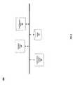
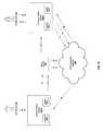
- the communication devices 200combine the presence feature 205 and the callback feature 215 in a single device.
- the featuresmay be in separate devices capable of communicating with each other directly or via the communication network 100 .
- the presence featuremay be in a PDA 150 and the callback feature may be in a wired telephone 120 , where both devices are connected via communication network 100 .
Landscapes
- Engineering & Computer Science (AREA)
- Signal Processing (AREA)
- Telephonic Communication Services (AREA)
Abstract
Description
Claims (6)
Priority Applications (2)
| Application Number | Priority Date | Filing Date | Title |
|---|---|---|---|
| US11/318,486US8649485B2 (en) | 2005-12-28 | 2005-12-28 | System and method for automated connection triggered by availability status |
| US14/071,033US9071686B2 (en) | 2005-12-28 | 2013-11-04 | System and method for automated connection triggered by availability status |
Applications Claiming Priority (1)
| Application Number | Priority Date | Filing Date | Title |
|---|---|---|---|
| US11/318,486US8649485B2 (en) | 2005-12-28 | 2005-12-28 | System and method for automated connection triggered by availability status |
Related Child Applications (1)
| Application Number | Title | Priority Date | Filing Date |
|---|---|---|---|
| US14/071,033ContinuationUS9071686B2 (en) | 2005-12-28 | 2013-11-04 | System and method for automated connection triggered by availability status |
Publications (2)
| Publication Number | Publication Date |
|---|---|
| US20070147596A1 US20070147596A1 (en) | 2007-06-28 |
| US8649485B2true US8649485B2 (en) | 2014-02-11 |
Family
ID=38193745
Family Applications (2)
| Application Number | Title | Priority Date | Filing Date |
|---|---|---|---|
| US11/318,486Active2031-12-03US8649485B2 (en) | 2005-12-28 | 2005-12-28 | System and method for automated connection triggered by availability status |
| US14/071,033ActiveUS9071686B2 (en) | 2005-12-28 | 2013-11-04 | System and method for automated connection triggered by availability status |
Family Applications After (1)
| Application Number | Title | Priority Date | Filing Date |
|---|---|---|---|
| US14/071,033ActiveUS9071686B2 (en) | 2005-12-28 | 2013-11-04 | System and method for automated connection triggered by availability status |
Country Status (1)
| Country | Link |
|---|---|
| US (2) | US8649485B2 (en) |
Families Citing this family (12)
| Publication number | Priority date | Publication date | Assignee | Title |
|---|---|---|---|---|
| US8296370B2 (en)* | 2006-02-13 | 2012-10-23 | Research In Motion Limited | System and method of sharing auto-reply information |
| US8054961B2 (en)* | 2006-09-29 | 2011-11-08 | Siemens Enterprise Communications, Inc. | MeetMe assistant |
| US20080091782A1 (en)* | 2006-10-13 | 2008-04-17 | Gabriel Jakobson | Method and system for delegating and managing tasks over instant messenger |
| US8189759B2 (en)* | 2007-06-21 | 2012-05-29 | Mitel Networks Corporation | System and method for automatic call back using availability information |
| US20100174560A1 (en)* | 2008-03-27 | 2010-07-08 | Tom Quan | Method, system and apparatus for assembling data associated with an emergency call event |
| US20090248476A1 (en) | 2008-03-27 | 2009-10-01 | Mitel Networks Corporation | Method, system and apparatus for controlling an application |
| US20090248464A1 (en)* | 2008-03-27 | 2009-10-01 | Mitel Networks Corporation | Method, system and apparatus for managing context |
| US8572226B2 (en)* | 2008-12-17 | 2013-10-29 | Sap Ag | Enhancing network details using network monitoring scripts |
| US8594296B2 (en)* | 2009-05-20 | 2013-11-26 | Microsoft Corporation | Multimodal callback tagging |
| US8554856B2 (en) | 2010-11-08 | 2013-10-08 | Yagi Corp. | Enforced unitasking in multitasking systems |
| US9065786B2 (en)* | 2010-09-24 | 2015-06-23 | Yagi Corp. | Context-sensitive auto-responder |
| US11140107B2 (en)* | 2017-01-27 | 2021-10-05 | Advanced Micro Devices, Inc. | System and method of managing electronic meeting invitations |
Citations (24)
| Publication number | Priority date | Publication date | Assignee | Title |
|---|---|---|---|---|
| US5268957A (en)* | 1991-06-24 | 1993-12-07 | Rolm Company | Automatic call-back "camp-on" service for communication systems |
| US6278454B1 (en)* | 1998-09-24 | 2001-08-21 | Ericsson Inc. | Call progress graphical user interface |
| US6363065B1 (en)* | 1999-11-10 | 2002-03-26 | Quintum Technologies, Inc. | okApparatus for a voice over IP (voIP) telephony gateway and methods for use therein |
| US20020136206A1 (en)* | 2001-03-20 | 2002-09-26 | Worldcom, Inc. | Recursive query for communications network data |
| US20020181670A1 (en)* | 1998-12-28 | 2002-12-05 | John C. Myers | Telephony call control using a data network and a graphical user interface and exchanging datagrams between parties to a telephone call |
| US20030041101A1 (en)* | 2001-08-24 | 2003-02-27 | Hansche Brian A. | Presence watcher proxy |
| US20030229670A1 (en)* | 2002-06-11 | 2003-12-11 | Siemens Information And Communication Networks, Inc. | Methods and apparatus for using instant messaging as a notification tool |
| US20030229722A1 (en)* | 2002-06-11 | 2003-12-11 | Siemens Information And Communication Networks, Inc. | Methods and apparatus for processing an instant message |
| US6683941B2 (en)* | 2001-12-17 | 2004-01-27 | International Business Machines Corporation | Controlling advertising output during hold periods |
| US20040205175A1 (en)* | 2003-03-11 | 2004-10-14 | Kammerer Stephen J. | Communications system for monitoring user interactivity |
| US20050068167A1 (en)* | 2003-09-26 | 2005-03-31 | Boyer David G. | Programmable presence proxy for determining a presence status of a user |
| US20050262435A1 (en)* | 2003-10-30 | 2005-11-24 | Avaya Technology Corp. | Automatic detection and dialing of phone numbers on computer documents |
| US20060010379A1 (en)* | 2003-10-30 | 2006-01-12 | Avaya Technology Corp. | Automatic identification and storage of context information associated with phone numbers in computer documents |
| US7065197B1 (en)* | 2002-10-23 | 2006-06-20 | Cisco Technology, Inc. | Status messaging using associated phone tags |
| US20060190117A1 (en)* | 2003-06-27 | 2006-08-24 | Hewlett-Packard Development Copany L.P. | Method and apparatus for automatically determining a presence status |
| US7123695B2 (en)* | 2002-05-21 | 2006-10-17 | Bellsouth Intellectual Property Corporation | Voice message delivery over instant messaging |
| US20060259474A1 (en)* | 2005-05-11 | 2006-11-16 | Jennifer Granito | Searching electronic content in instant-messaging applications |
| US20070081651A1 (en)* | 2005-09-28 | 2007-04-12 | Radha Iyer | Method and apparatus for automatic conference call invocation based on user presence |
| US7218722B1 (en)* | 2000-12-18 | 2007-05-15 | Westell Technologies, Inc. | System and method for providing call management services in a virtual private network using voice or video over internet protocol |
| US7280530B2 (en)* | 1997-07-25 | 2007-10-09 | Starvox Communications Inc. | Apparatus and method for integrated voice gateway |
| US7353455B2 (en)* | 2002-05-21 | 2008-04-01 | At&T Delaware Intellectual Property, Inc. | Caller initiated distinctive presence alerting and auto-response messaging |
| US7480260B1 (en)* | 2004-05-13 | 2009-01-20 | 3Com Corporation | Method and apparatus for implementing a presence-based universal camp-on feature in packet-based telephony systems |
| US7660849B1 (en)* | 1999-12-14 | 2010-02-09 | Cisco Technology, Inc. | Extending camp-on capabilities to invitees to an ongoing converence call |
| US7668305B2 (en)* | 2004-07-14 | 2010-02-23 | Fujitsu Limited | Communication system based on SIP, and communication terminal |
Family Cites Families (9)
| Publication number | Priority date | Publication date | Assignee | Title |
|---|---|---|---|---|
| US6882708B1 (en)* | 1999-02-26 | 2005-04-19 | Bellsouth Intellectual Property Corporation | Region-wide messaging system and methods including validation of transactions |
| US6707890B1 (en)* | 2002-09-03 | 2004-03-16 | Bell South Intellectual Property Corporation | Voice mail notification using instant messaging |
| US7167701B1 (en)* | 2001-12-18 | 2007-01-23 | Bellsouth Intellectual Property Corporation | Voice mailbox with management support |
| US6957077B2 (en)* | 2002-05-06 | 2005-10-18 | Microsoft Corporation | System and method for enabling instant messaging on a mobile device |
| US7657598B2 (en)* | 2002-09-17 | 2010-02-02 | At&T Intellectual Property I, L.P. | Address book for integrating email and instant messaging (IM) |
| US7921160B2 (en)* | 2002-09-17 | 2011-04-05 | At&T Intellectual Property I, L.P. | Initiating instant messaging (IM) chat sessions from email messages |
| US7933957B2 (en)* | 2002-09-17 | 2011-04-26 | At&T Intellectual Property Ii, L.P. | Tracking email and instant messaging (IM) thread history |
| US7603420B2 (en)* | 2004-03-31 | 2009-10-13 | International Business Machines Corporation | Method and apparatus for automatic e-mail response interruption based on user activity |
| US7716294B2 (en)* | 2005-09-07 | 2010-05-11 | International Busines Machines Corporation | Method, system, and computer program product for providing an instant messaging interface with dynamically generated message buttons |
- 2005
- 2005-12-28USUS11/318,486patent/US8649485B2/enactiveActive
- 2013
- 2013-11-04USUS14/071,033patent/US9071686B2/enactiveActive
Patent Citations (26)
| Publication number | Priority date | Publication date | Assignee | Title |
|---|---|---|---|---|
| US5268957A (en)* | 1991-06-24 | 1993-12-07 | Rolm Company | Automatic call-back "camp-on" service for communication systems |
| US7280530B2 (en)* | 1997-07-25 | 2007-10-09 | Starvox Communications Inc. | Apparatus and method for integrated voice gateway |
| US6278454B1 (en)* | 1998-09-24 | 2001-08-21 | Ericsson Inc. | Call progress graphical user interface |
| US20020181670A1 (en)* | 1998-12-28 | 2002-12-05 | John C. Myers | Telephony call control using a data network and a graphical user interface and exchanging datagrams between parties to a telephone call |
| US6665293B2 (en)* | 1999-11-10 | 2003-12-16 | Quintum Technologies, Inc. | Application for a voice over IP (VoIP) telephony gateway and methods for use therein |
| US6363065B1 (en)* | 1999-11-10 | 2002-03-26 | Quintum Technologies, Inc. | okApparatus for a voice over IP (voIP) telephony gateway and methods for use therein |
| US7660849B1 (en)* | 1999-12-14 | 2010-02-09 | Cisco Technology, Inc. | Extending camp-on capabilities to invitees to an ongoing converence call |
| US7218722B1 (en)* | 2000-12-18 | 2007-05-15 | Westell Technologies, Inc. | System and method for providing call management services in a virtual private network using voice or video over internet protocol |
| US20020136206A1 (en)* | 2001-03-20 | 2002-09-26 | Worldcom, Inc. | Recursive query for communications network data |
| US20030041101A1 (en)* | 2001-08-24 | 2003-02-27 | Hansche Brian A. | Presence watcher proxy |
| US6683941B2 (en)* | 2001-12-17 | 2004-01-27 | International Business Machines Corporation | Controlling advertising output during hold periods |
| US7123695B2 (en)* | 2002-05-21 | 2006-10-17 | Bellsouth Intellectual Property Corporation | Voice message delivery over instant messaging |
| US7353455B2 (en)* | 2002-05-21 | 2008-04-01 | At&T Delaware Intellectual Property, Inc. | Caller initiated distinctive presence alerting and auto-response messaging |
| US20030229670A1 (en)* | 2002-06-11 | 2003-12-11 | Siemens Information And Communication Networks, Inc. | Methods and apparatus for using instant messaging as a notification tool |
| US20030229722A1 (en)* | 2002-06-11 | 2003-12-11 | Siemens Information And Communication Networks, Inc. | Methods and apparatus for processing an instant message |
| US7065197B1 (en)* | 2002-10-23 | 2006-06-20 | Cisco Technology, Inc. | Status messaging using associated phone tags |
| US20040205175A1 (en)* | 2003-03-11 | 2004-10-14 | Kammerer Stephen J. | Communications system for monitoring user interactivity |
| US20060190117A1 (en)* | 2003-06-27 | 2006-08-24 | Hewlett-Packard Development Copany L.P. | Method and apparatus for automatically determining a presence status |
| US20090009343A1 (en)* | 2003-09-26 | 2009-01-08 | Avaya Inc. | Programmable Presence Proxy for Determining a Presence Status of a User |
| US20050068167A1 (en)* | 2003-09-26 | 2005-03-31 | Boyer David G. | Programmable presence proxy for determining a presence status of a user |
| US20050262435A1 (en)* | 2003-10-30 | 2005-11-24 | Avaya Technology Corp. | Automatic detection and dialing of phone numbers on computer documents |
| US20060010379A1 (en)* | 2003-10-30 | 2006-01-12 | Avaya Technology Corp. | Automatic identification and storage of context information associated with phone numbers in computer documents |
| US7480260B1 (en)* | 2004-05-13 | 2009-01-20 | 3Com Corporation | Method and apparatus for implementing a presence-based universal camp-on feature in packet-based telephony systems |
| US7668305B2 (en)* | 2004-07-14 | 2010-02-23 | Fujitsu Limited | Communication system based on SIP, and communication terminal |
| US20060259474A1 (en)* | 2005-05-11 | 2006-11-16 | Jennifer Granito | Searching electronic content in instant-messaging applications |
| US20070081651A1 (en)* | 2005-09-28 | 2007-04-12 | Radha Iyer | Method and apparatus for automatic conference call invocation based on user presence |
Also Published As
| Publication number | Publication date |
|---|---|
| US20140050310A1 (en) | 2014-02-20 |
| US9071686B2 (en) | 2015-06-30 |
| US20070147596A1 (en) | 2007-06-28 |
Similar Documents
| Publication | Publication Date | Title |
|---|---|---|
| US9071686B2 (en) | System and method for automated connection triggered by availability status | |
| US8824643B2 (en) | System, method and computer program product for conveying presence information via voice mail | |
| US10075589B2 (en) | Data and call routing and forwarding | |
| US7917582B2 (en) | Method and apparatus for autocorrelation of instant messages | |
| US7130390B2 (en) | Audio messaging system and method | |
| JP3370394B2 (en) | E-mail system linked with telephone | |
| US7328031B2 (en) | Message exchange handling concept | |
| US7694313B2 (en) | Terminating device and a method of operating a terminating device configured to communicate availability status directly between terminating devices | |
| US7587457B2 (en) | Message automatic notification system, message automatic notification method, communication terminal device, and recording medium | |
| US20060193448A1 (en) | Method and apparatus for augmenting voice data on a mobile device call | |
| US7970391B2 (en) | Managing availability status in a communications network | |
| KR20040053341A (en) | Sending voicemail messages to multiple users | |
| US7685608B2 (en) | Data processing apparatus and a method of operating data processing apparatus for generating representations of availability status for application programs | |
| US20120327814A1 (en) | Communication using delegates, such as delegates specified in an email or scheduling application | |
| JP2001313666A (en) | Instant message communication system | |
| JP2022125163A (en) | Information processing system | |
| JP2023141834A (en) | Response system and response method | |
| CN102664818B (en) | For the terminal, the method and system that communicate | |
| JP2011109214A (en) | Line congestion resolution system | |
| JP5351261B2 (en) | Information recovery from telephone terminals via communication server | |
| JPH10107901A (en) | Message notice system | |
| JP4725247B2 (en) | Workplace providing system and method | |
| US7848503B2 (en) | Method for processing an untaken call on a called communication terminal | |
| KR20020094339A (en) | Method and system for transferring call messages received while user is absent | |
| JPH07177236A (en) | Real-time / storage integrated voice communication device |
Legal Events
| Date | Code | Title | Description |
|---|---|---|---|
| AS | Assignment | Owner name:SAP AG, GERMANY Free format text:ASSIGNMENT OF ASSIGNORS INTEREST;ASSIGNOR:MOSER, MARTIN K.;REEL/FRAME:017792/0042 Effective date:20060419 | |
| FEPP | Fee payment procedure | Free format text:PAYOR NUMBER ASSIGNED (ORIGINAL EVENT CODE: ASPN); ENTITY STATUS OF PATENT OWNER: LARGE ENTITY | |
| STCF | Information on status: patent grant | Free format text:PATENTED CASE | |
| AS | Assignment | Owner name:SAP SE, GERMANY Free format text:CHANGE OF NAME;ASSIGNOR:SAP AG;REEL/FRAME:033625/0334 Effective date:20140707 | |
| FEPP | Fee payment procedure | Free format text:PAYOR NUMBER ASSIGNED (ORIGINAL EVENT CODE: ASPN); ENTITY STATUS OF PATENT OWNER: LARGE ENTITY Free format text:PAYER NUMBER DE-ASSIGNED (ORIGINAL EVENT CODE: RMPN); ENTITY STATUS OF PATENT OWNER: LARGE ENTITY | |
| FPAY | Fee payment | Year of fee payment:4 | |
| MAFP | Maintenance fee payment | Free format text:PAYMENT OF MAINTENANCE FEE, 8TH YEAR, LARGE ENTITY (ORIGINAL EVENT CODE: M1552); ENTITY STATUS OF PATENT OWNER: LARGE ENTITY Year of fee payment:8 | |
| MAFP | Maintenance fee payment | Free format text:PAYMENT OF MAINTENANCE FEE, 12TH YEAR, LARGE ENTITY (ORIGINAL EVENT CODE: M1553); ENTITY STATUS OF PATENT OWNER: LARGE ENTITY Year of fee payment:12 |