US8648867B2 - Graphic processor based accelerator system and method - Google Patents
Graphic processor based accelerator system and methodDownload PDFInfo
- Publication number
- US8648867B2 US8648867B2US11/860,254US86025407AUS8648867B2US 8648867 B2US8648867 B2US 8648867B2US 86025407 AUS86025407 AUS 86025407AUS 8648867 B2US8648867 B2US 8648867B2
- Authority
- US
- United States
- Prior art keywords
- accelerator
- processing unit
- memory
- computational
- data
- Prior art date
- Legal status (The legal status is an assumption and is not a legal conclusion. Google has not performed a legal analysis and makes no representation as to the accuracy of the status listed.)
- Active, expires
Links
Images


Classifications
- G—PHYSICS
- G06—COMPUTING OR CALCULATING; COUNTING
- G06F—ELECTRIC DIGITAL DATA PROCESSING
- G06F9/00—Arrangements for program control, e.g. control units
- G06F9/06—Arrangements for program control, e.g. control units using stored programs, i.e. using an internal store of processing equipment to receive or retain programs
- G06F9/46—Multiprogramming arrangements
- G06F9/50—Allocation of resources, e.g. of the central processing unit [CPU]
- G06F9/5005—Allocation of resources, e.g. of the central processing unit [CPU] to service a request
- G06F9/5027—Allocation of resources, e.g. of the central processing unit [CPU] to service a request the resource being a machine, e.g. CPUs, Servers, Terminals
- G—PHYSICS
- G06—COMPUTING OR CALCULATING; COUNTING
- G06T—IMAGE DATA PROCESSING OR GENERATION, IN GENERAL
- G06T1/00—General purpose image data processing
- G06T1/20—Processor architectures; Processor configuration, e.g. pipelining
- G—PHYSICS
- G06—COMPUTING OR CALCULATING; COUNTING
- G06T—IMAGE DATA PROCESSING OR GENERATION, IN GENERAL
- G06T1/00—General purpose image data processing
- G06T1/60—Memory management
- G—PHYSICS
- G06—COMPUTING OR CALCULATING; COUNTING
- G06F—ELECTRIC DIGITAL DATA PROCESSING
- G06F2209/00—Indexing scheme relating to G06F9/00
- G06F2209/50—Indexing scheme relating to G06F9/50
- G06F2209/509—Offload
- G—PHYSICS
- G06—COMPUTING OR CALCULATING; COUNTING
- G06N—COMPUTING ARRANGEMENTS BASED ON SPECIFIC COMPUTATIONAL MODELS
- G06N20/00—Machine learning
- G—PHYSICS
- G06—COMPUTING OR CALCULATING; COUNTING
- G06N—COMPUTING ARRANGEMENTS BASED ON SPECIFIC COMPUTATIONAL MODELS
- G06N3/00—Computing arrangements based on biological models
- G06N3/02—Neural networks
- G06N3/06—Physical realisation, i.e. hardware implementation of neural networks, neurons or parts of neurons
- G06N3/063—Physical realisation, i.e. hardware implementation of neural networks, neurons or parts of neurons using electronic means
Definitions
- GPUsGraphics Processing Units
- PCspersonal computers
- PCspersonal computers
- PCspersonal computers
- PCspersonal computers
- workstationsworkstations
- GPUsGraphics Processing Units
- GPUshave included general purpose programmability into the GPU architecture leading to the increased popularity of using GPUs for highly parallelizable and computationally expensive algorithms outside of the computer graphics domain.
- GPUsgeneral purpose GPU
- these general purpose GPU (GPGPU) applicationsare not able to achieve optimal performance, however.
- Numerical simulationse.g., finite element analysis, of large systems of similar elements (e.g. neural networks, genetic algorithms, particle systems, mechanical systems) are one example of an application that can benefit from GPGPU computation.
- disk and user input/outputcan be performed independently of computation because these two processes require interactions with peripheral hardware (disk, screen, keyboard, mouse, etc) and put relatively low load on the central processing unit/system (CPU).
- CPUcentral processing unit/system
- Complete independenceis not desirable, however; user input might affect how the computation is performed and even interrupt it if necessary.
- the user output and the disk outputare dependent on the results of the computation.
- a reasonable solutionwould be to separate input/output into threads, so that it is interacting with hardware occurs in parallel with the computation. In this case whatever CPU processing is required for input/output should be designed so that it provides the synchronization with computation.
- the central processing unitestablishes communication and synchronization between peripherals.
- peripheralsare preferably controlled by a dedicated thread that is executed in parallel with minimal interactions and dependencies on the other threads.
- a GPU on a conventional video cardis usually controlled through OpenGL, DirectX, or similar graphic application programming interfaces (APIs).
- APIsestablish the context of graphic operations, within which all calls to the GPU are made. This context only works when initialized within the same thread of execution that uses it. As a result, in a preferred embodiment, the context is initialized within a computational thread. This creates complications, however, in the interaction between the user interface thread that changes parameters of simulations and the computational thread that uses these parameters.
- a solution as proposed hereis an implementation of the computational stream of execution in hardware, so that thread and context initialization are replaced by hardware initialization.
- This hardware implementationincludes an expansion card comprising a printed circuit board having (a) one or more graphics processing units, (b) two or more associated memory banks that are logically or physically partitioned, (c) a specialized controller, and (d) a local bus providing signal coupling compatible with the PCI industry standards (this includes but is not limited to PCI-Express, PCI-X, USB 2.0, or functionally similar technologies).
- the controllerhandles most of the primitive operations needed to set up and control GPU computation. As a result, the CPU is freed from this function and is dedicated to other tasks.
- the inventionfeatures a computer system.
- This systemcomprises a central processing unit, main memory accessed by the central processing unit, and a video system for driving a video monitor in response to the central processing unit as is common.
- the computer systemfurther comprises an accelerator that uses input data from and provides output data to the central processing unit.
- This acceleratorcomprises at least one graphics processing unit, accelerator memory for the graphic processing unit, and an accelerator controller that moves the input data into the at least one graphics processing unit and the accelerator memory to generate the output data.
- the central processing unittransfers the input data for a simulation to the accelerator, after which the accelerator executes simulation computations to generate the output data, which is transferred to the central processing unit.
- the accelerator controllerdictates an order of execution of instructions to the at least one graphics processing unit. The use of the separate controller enables data transfer during execution such that the accelerator controller transfers output data from the accelerator memory to main memory of the central processing unit.
- the accelerator controllercomprises an interface controller that enables the accelerator to communicate over a bus of the computer system with the central processing unit.
- the inventionalso features an accelerator system for a computer system, which comprises at least one graphics processing unit, accelerator memory for the graphic processing unit and an accelerator controller for moving data between the at least one graphics processing unit and the accelerator memory.
- the inventionalso features a method for performing numerical simulations in a computer system.
- This methodcomprises a central processing unit loading input data into an accelerator system from main memory of the central processing unit and an accelerator controller transferring the input data to a graphics processing unit with instructions to be performed on the input data.
- the accelerator controllerthen transfers output data generated by the graphic processing unit to the central processing unit as output data.
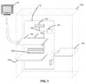
- FIG. 1is a schematic diagram illustrating a computer system including the GPU accelerator according to an embodiment of the present invention
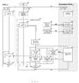
- FIG. 2is block diagram illustrating the architecture for the GPU accelerator according to an embodiment of the present invention
- FIG. 3is a block/flow diagram illustrating an exemplary implementation of the top level control of the GPU accelerator system
- FIG. 4is a flow diagram illustrating an exemplary implementation of the bottom level control of the GPU accelerator system that is used to execute the target computation
- FIG. 5is an example population of nine computational elements arranged in a 3 ⁇ 3 square and a potential packing scheme for texture pixels, according to an implementation of the present invention.
- FIG. 1shows a computer system 100 that has been constructed according to the principles of the present invention.
- the computer system 100 in one exampleis a standard personal computer (PC).
- PCpersonal computer
- suitable computing environments for this inventionincluding, but not limited to, workstations, server computers, supercomputers, notebook computers, hand-held electronic devices such as cell phones, mp3 players, or personal digital assistants (PDAs), multiprocessor systems, programmable consumer electronics, networks of any of the above-mentioned computing devices, and distributed computing environments that including any of the above-mentioned computing devices.
- the GPU acceleratoris implemented as an expansion card 180 includes connections with the motherboard 110 , on which the one or more CPU's 120 are installed along with main, or system memory 130 and mass/non volatile data storage 140 , such as hard drive or redundant array of independent drives (RAID) array, for the computer system 100 .
- the expansion card 180communicates to the motherboard 110 via a local bus 190 .
- This local bus 190could be PCI, PCI Express, PCI-X, or any other functionally similar technology (depending upon the availability on the motherboard 110 ).
- An external version GPU acceleratoris also a possible implementation.
- the external GPU acceleratoris connected to the motherboard 110 through USB-2.0, IEEE 1394 (Firewire), or similar external/peripheral device interface.
- the CPU 120 and the system memory 130 on the motherboard 110 and the mass data storage system 140are preferably independent of the expansion card 180 and only communicate with each other and the expansion card 180 through the system bus 200 located in the motherboard 110 .
- a system bus 200 in current generations of computershave bandwidths from 3.2 GB/s (Pentium 4 with AGTL+, Athlon XP with EV6) to around 15 GB/s (Xeon Woodcrest with AGTL+, Athlon 64/Opteron with Hypertransport), while the local bus has maximal peak data transfer rates of 4 GB/s (PCI Express 16) or 2 GB/s (PCI-X 2.0).
- PCI Express 16PCI Express 16
- PCI-X 2.0PCI-X 2.0
- the system memory 130is referred to as the main random-access memory (RAM) in the description herein. However, this is not intended to limit the system memory 130 to only RAM technology.
- RAMmain random-access memory
- Other possible computer storage mediainclude, but are not limited to ROM, EEPROM, flash memory, or any other memory technology.
- the GPU accelerator systemis implemented on an expansion card 180 on which the one or more GPU's 240 are mounted. It should be noted that the GPU accelerator system GPU 240 is separate from and independent of any GPU on the standard video card 150 or other video driving hardware such as integrated graphics systems. Thus the computations performed on the expansion card 180 do not interfere with graphics display (including but not limited to manipulation and rendering of images).
- GPUVarious brand of GPU are relevant. Under current technology, GPU's based on the GeForce series from NVIDIA Corporation or the Catalyst series from ATI/Advanced Micro Devices, Inc.
- the output to a video monitor 170is preferably through the video card 150 and not the GPU accelerator system 180 .
- the video card 150is dedicated to the transfer of graphical information and connects to the motherboard 110 through a local bus 160 that is sometimes physically separate from the local bus 190 that connects the expansion card 180 to the motherboard 110 .
- FIG. 2is a block diagram illustrating the general architecture of the GPU accelerator system and specifically the expansion card 180 in which at least one GPU 240 and associated memories 210 and 250 are mounted. Electrical (signal) and mechanical coupling with a local bus 190 provides signal coupling compatible with the PCI industry standards (this includes but is not limited to PCI, PCI-X, PCI Express, or functionally similar technology).
- the GPU acceleratorfurther preferably comprises one specifically designed accelerator controller 220 .
- the accelerator controller 220is field programmable gate array (FPGA) logic, or custom built application-specific (ASIC) chip mounted in the expansion card 180 , and in mechanical and signal coupling with the GPU 240 and the associated memories 210 and 250 .
- FPGAfield programmable gate array
- ASICapplication-specific
- the controller 220commands the storage and retrieval of arrays of data (on a conventional video card the arrays of data are represented as textures, hence the term ‘texture’ in this document refers to a data array unless specified otherwise and each element of the texture is a pixel of color information), execution of GPU programs (on a conventional video card these programs are called shaders, hence the term ‘shader’ in this document refers to a GPU program unless specified otherwise), and data transfer between the system bus 200 and the expansion card 180 through the local bus 190 which allows communication between the main CPU 120 , RAM 130 , and disk 140 .
- textureshence the term ‘texture’ in this document refers to a data array unless specified otherwise and each element of the texture is a pixel of color information
- execution of GPU programson a conventional video card these programs are called shaders, hence the term ‘shader’ in this document refers to a GPU program unless specified otherwise
- data transfer between the system bus 200 and the expansion card 180 through the local bus 190which allows communication between the main
- Two memory banks 210 and 250are mounted on the expansion card 180 .
- these memory banksseparated in the hardware, as shown, or alternatively implemented as a single, logically partitioned memory component.
- the reason to separate the memory into two partitions 210 250stems from the nature of the computations to which the GPU accelerator system is applied.
- the elements of computationare characterized by a single output variable. Such computational elements often include one or more equations. Computational elements are same or similar within a large population and are computed in parallel. An example of such a population is a layer of neurons in an artificial neural network (ANN), where all neurons are described by the same equation.
- ANNartificial neural network
- one memorythe shader memory bank 210
- the texture memory bank 250is used to store all the necessary data that are specific for every computational element (including, but not limited to, input data, output data, intermediate results, and parameters) and is coupled with both the controller 220 and the GPU 240 .
- the texture memory bank 250is preferably further partitioned into four sections.
- the first partition 250 ais designed to hold the external input data patterns.
- the second partition 250 bis designed to hold the data textures representing internal variables.
- the third partition 250 cis designed to hold the data textures used as input at a particular computation step on the GPU 240 .
- the fourth partition 250 dholds the data textures used to accommodate the output of a particular computational step on the GPU 240 .
- This partitioning schemecan be done logically, does not require hardware implementation. Also the partitioning scheme is also altered based on new designs or needs of the algorithms being employed. The reason for this partitioning is further explained in the Data Organization section, below.
- a local bus interface 230 on the controller 220serves as a driver that allows the controller 220 to communicate through the local bus 190 with the system bus 200 and thus the CPU 120 and RAM 130 .
- This local bus interface 230is not intended to be limited to PCI related technology. Other drivers can be used to interface with comparable technology as a local bus 190 .
- Each computational element discussed abovehas output variables that affect the rest of the system. For example in the case of a neural network it is the output of a neuron.
- a computational elementalso usually has several internal variables that are used to compute output variables, but are not exposed to the rest of the system, not even to other elements of the same population, typically. Each of these variables is represented as a texture. The important difference between output variables and internal variables is their access.
- Output variablesare usually accessed by any element in the system during every time step.
- the value of the output variable that is accessed by other elements of the systemcorresponds to the value computed on the previous, not the current, time step.
- Thisis realized by dedicating two textures to output variables—one holds the value computed during the previous time step and is accessible to all computational elements during the current time step, another is not accessible to other elements and is used to accumulate new values for the variable computed during the current time step. In-between time steps these two textures are switched, so that newly accumulated values serve as accessible input during the next time step, while the old input is replaced with new values of the variable.
- This switchis implemented by swapping the address pointers to respective textures as described in the System and Framework section.
- Texturescan have up to four color components that are all processed in parallel on a GPU.
- texture elementcan have up to four color components that are all processed in parallel on a GPU.
- designating one texture pixel per elementis ineffective because internal variables require one texture and output variables require two textures.
- different element typeshave different numbers of variables and unless this number is precisely a multiple of four, texture memory can be wasted.
- FIG. 5 aAn example population of nine computational elements arranged in a 3 ⁇ 3 square ( FIG. 5 a ) can be packed by element ( FIG. 5 b ), by row ( FIG. 5 c ), or by square ( FIG. 5 d ).
- Packing by elementmeans that elements 1 , 2 , 3 , 4 go into first pixel; 5 , 6 , 7 , 8 go into second pixel; 9 goes into third pixel. This is the most compact scheme, but not convenient because the geometrical relationship is not preserved during packing and its extraction depends on the size of the population.
- Packing by rowmeans that elements 1 , 2 , 3 go into pixel (1,1); 3 , 4 , 5 go into pixel (2,1), 7 , 8 , 9 go into pixel (3,1).
- the element's y coordinate in the populationis the pixel's y coordinate
- the element's x coordinate in the populationis the pixel's x coordinate times four plus the index of color component.
- Five by five populations in this casewill use 2 ⁇ 5 texture, or 10 pixels. Five of these pixels will only use one out of four components, so it wastes 37.5% of this texture.
- 25 ⁇ 1 populationwill use 6 ⁇ 1 texture (six pixels) and will waste 12.5% of it.
- Packing by squaremeans that elements 1 , 2 , 4 , 5 go into pixel (1,1); 3 , 6 go into pixel (1,2); 7 , 8 go into pixel (2,1), and 9 goes into pixel (2,2).
- Both the row and the column of the elementare determined from the row (column) of the pixel times two plus the second (first) bit of the color component index.
- Five by five populations in this casewill use 3 ⁇ 3 texture, or 9 pixels.
- Four of these pixelswill only use two out of four components, and one will only use one component, so it wastes 34.4% of this texture. This is more advantageous than packing by row, since the texture is smaller and the waste is also lower.
- 25 ⁇ 1 population on the other handwill use 13 ⁇ 1 texture (thirteen pixels) and waste >50% of it, which is much worse than packing by row.
- FIG. 3shows an exemplary implementation of the top level system and method that is used to control the computation. It is a representation of one of several ways in which a system and method for processing numerical techniques can be implemented in the invention described herein and so the implementation is not intended to be limited to the following description and accompanying figure.
- the method presented hereinincludes two execution streams that run on the CPU 120 —User Interaction Stream 302 and Data Output Stream 301 . These two streams preferably do not interact directly, but depend on the same data accumulated during simulations. They can be implemented as separate threads with shared memory access and executed on different CPUs in the case of multi-CPU computing environment.
- the Computational Stream 303interacts with the User Interaction Stream and the Data Output Stream through synchronization procedures during simulations.
- the crucial feature of the interaction between the User Interaction Stream 302 and the Computational Stream 303is the shift of priorities. Outside of the simulation, the system 100 is driven by the user input, thus the User Interaction Stream 302 has the priority and controls the data exchange 304 between streams. After the user starts the simulation, the Computational Stream 303 takes the priority and controls the data exchange between streams until the simulation is finished or interrupted 350 .
- the userstarts 300 the framework through the means of an operating system and interacts with the software through the user interaction section 305 of the graphic user interface 306 executed on the CPU 120 .
- the start 300 of the implementationbegins with a user action that causes a GUI initialization 307 , Disk input/output initialization 308 on the CPU 120 , and controller initialization 320 of the GPU accelerator on the expansion card 180 .
- GUI initializationincludes opening of the main application window and setting the interface tools that allow the user to control the framework.
- Disk I/O initializationcan be performed at the start of the framework, or at the start of each individual simulation.
- the user interaction 305controls the setting and editing of the computational elements, parameters, and sources of external inputs. It specifies which equations should have their output saved to disk and/or displayed on the screen. It allows the user to start and stop the simulation. And it performs standard interface functions such as file loading and saving, interactive help, general preferences and others.
- the user interaction 305directs the CPU 120 to acquire the new external input textures needed (this includes but is not limited to loading from disk 140 or receiving them in real time from a recording device), parses them if necessary 309 , and initializes their transfer to the expansion card 180 , where they are stored 325 in the texture memory bank 250 by the controller 220 .
- the user interaction 305also directs the CPU 120 to parse populations of elements that will be used in the simulation, convert them to GPU programs (shaders), compile them 310 , and initializes their transfer to the expansion card 180 , where they are stored 326 in the shader memory bank 210 by the controller 220 .
- This operationis accompanied by the upload 309 of the initial data into the input partition of the texture memory bank 250 , and stores the shader order of execution in the controller 220 .
- the usercan perform operations 309 and 310 as many times as necessary prior to starting the simulation or between simulations.
- the editing of the system between simulationsis difficult to accomplish without the hardware implementation of the computational thread suggested herein.
- the system of equationsis represented by textures that track variables plus shaders that define processing algorithms.
- textures, shaders and other graphics related constructscan only be initialized within the rendering context, which is thread specific. Therefore textures and shaders can only be initialized in the computational thread.
- Network editingis a user-interactive process, which according to the scheme suggested above happens in the User Interaction Stream 302 .
- the simulation softwarethus has to take the new parameters from the User Interaction Stream 302 , communicate them to the Computational Stream 303 and regenerate the necessary shaders and textures. This is hard to accomplish without a hardware implementation of the Computational Stream 303 .
- the Computational Stream 303is forked from the User Interaction Stream and it can access the memory of the parent thread, but the reverse communication is harder to achieve.
- the controller 220allows operations 309 and 310 to be performed as many times as necessary by providing the necessary communication to the User Interaction Stream 302 .
- the userAfter execution of the input parser texture generation 309 and population parser shader generator and compiler 310 are performed at least once, the user has the option to initialize the simulation 311 .
- the main control of the frameworkis transferred to the GPU accelerator system's accelerator controller 220 and computation 330 is started (see FIG. 4 ; 420 ).
- the userretains the ability to interrupt the simulation, change the input, or to change the display properties of the framework, but these interactions are queued to be performed at times determined by the controller-driven data exchange 314 and 316 to avoid the corruption of the data.
- the progress monitor 312is not necessary for performance, but adds convenience. It displays the percentage of completed time steps of the simulation and allows the user to plan the schedule using the estimates of the simulation wall clock times. Controller-driven data exchange 314 updates the display of the results 313 . Online screen output for the user selected population allows the user to monitor the activity and evaluate the qualitative behavior of the network. Simulations with unsatisfactory behavior can be terminated early to change parameters and restart. Controller-driven data exchange 314 also drives the output of the results to disk 317 . Data output to disk for convenience can be done on an element per file basis.
- a suggested file formatincludes a leftmost column that displays a simulated time for each of the simulation steps and subsequent columns that display variable values during this time step in all elements with identical equations (e.g. all neurons in a layer of a neural network).
- Controller-driven data exchange or input parser texture generator 316allows the user to change input that is generated on the fly during the simulation. This allows the framework monitoring of the input that is coming from a recording device (video camera, microphone, cell recording electrode, etc) in real time. Similar to the initial input parser 309 , it preprocesses the input into a universal format of the data array suitable for texture generation and generates textures. Unlike the initial parser 309 , here the textures are transferred to hardware not whenever ready but upon the request of the controller 220 .
- the controller 220also drives the conditional testing 315 and 318 informs the CPU-bound streams whether the simulation is finished. If so, the control returns to the User Interaction Stream. The user then can change parameters or inputs ( 309 and 310 ), restart the simulation ( 311 ) or quit the framework ( 390 ).
- SANNDRASession Node Network Distributed Runtime Algorithm
- http://www.kinness.net/Docs/SANNDRA/htmlwas developed to accelerate and optimize processing of numerical integration of large non-homogenous systems of differential equations.
- This libraryis fully reworked in its version 2.x.x to support multiple computational backends including those based on multicore CPUs, GPUs and other processing systems.
- GPU based backend for SANNDRA-2.x.xcan serve as an example practical software implementation of the method and architecture described above and pictorially represented in FIG. 3 .
- TSimulator objecteither directly or through inheritance. This object will handle global simulation properties and control the User Interaction Stream, Data Output Stream, and Computational Stream.
- TSimulator::timestep( ), TSimulator::outfileInterval( ), and TSimulator::outmode( )the application can set the time step of the simulation, the time step of disk output, and the mode of the disk output.
- the external input patternshould be packed into a TPattern object and bound to the simulation object through TSimulator::resetInputs( ) method.
- TSimulator::simLength( )sets the length of the simulation.
- the second stepis to create at least one population of equations (TPopulation object).
- Populationholds one equation object TEquation.
- This objectcontains only a formula and does not hold element-specific data, so all elements of the population can share single TEquation.
- the TEquation objectis converted to a GPU program before execution.
- GPU programshave to be executed within a graphical context, which is stream specific.
- TSimulatorcreates this context within a Computational Stream, therefore all programs and data arrays that are necessary for computation have to be initialized within Computational Stream.
- Constructor of TPopulationis called from User Interaction Stream, so no GPU-related objects can be initialized in this constructor.
- TPopulation::fillElements( )is a virtual method designed to overcome this difficulty. It is called from within the Computational Stream after TSimulator::networkCreate( ) is called in the User Interaction Stream. A user has to override TPopulation::fillElements( ) to create TEquation and other computation related objects both element independent and element-specific. Element independent objects include subcomponents of TEquation and objects that describe how to handle interdependencies between variables implemented through derivatives of TGate class.
- Element-specific datais held in TElement objects. These objects hold references to TEquation and a set of TGate objects. There is one TElement per population, but the size of data arrays within this object corresponds to population size. All TElement objects have to be added to the TSimulator list of elements by calling TSimulator::addUnit( ) method from TPopulation::fillElements( ).
- TPopulation::fillElements( )should contain a set of TElement::add*Dependency( ) calls for each element. Each of these calls sets a corresponding dependency for every TGate object.
- TGate objectholds element independent part of dependency
- TElement::add*Dependency( )sets element-specific details.
- TPopulationhandles the output of computational elements, both when they need to exchange the data and when they need to output it to disk.
- User implementation of TPopulation derivativecan add screen output.
- Listing 1is an example code of the user program that uses a recurrent competitive field (RCF) equation:
- FIG. 4is a detailed flow diagram illustrating a part of an exemplary implementation of the bottom level system and method performed during the computation on the GPU accelerator of the expansion card 180 and is a more detailed view of the computational box 330 in FIG. 3 .
- FIG. 4is a representation of one of several ways in which a system and method for processing numerical techniques can be implemented.
- ID swappingis equivalent to swapping the base memory address for two partitions of the texture memory bank 250 . They are swapped 485 during synchronization ( 485 , 430 , and 455 ) so that data transfer 445 and the computation 435 - 487 proceeds immediately and in parallel with data transfer as shown in FIG. 4 .
- a hardware solutionallows this parallelism through access of the controller 220 to the onboard texture memory bank 250 .
- the main computation and data exchangeare executed by the controller 220 . It runs three parallel substreams of execution: Computational Substream 403 , Data Output Substream 402 , and Data Input Substream 404 . These streams are synchronized with each other during the swap of pointers 485 to the input and output texture memory partitions of the texture memory bank 250 and the check for the last iteration 487 . Algorithmically, these two operations are a single atomic operation, but the block diagram shows them as two separate blocks for clarity.
- the Computational Substream 403performs a computational cycle including a sequential execution of all shaders that were stored in the shader memory bank 210 using the appropriate input and output textures.
- the controller 220initializes three execution substreams 403 , 402 , and 404 .
- the Computational Substream 403determines which textures the GPU 240 will need to perform the computations and initiates the upload 435 of them onto the GPU 240 .
- the GPU 240can communicate directly with the texture memory bank 250 to upload the appropriate texture to perform the computations.
- the controller 220also pulls the first shader (known by the stored order) from the shader memory bank 210 and uploads 450 it onto the GPU 240 .
- the GPU 240executes the following operations in this order: performs the computation (execution of the shader) 470 ; tells the controller 220 that it is done with the computations for the current shader; and after all shaders for this particular equation are executed sends 480 the output textures to the output portion of the texture memory bank 250 . This cycle continues through all of the equations based on the branching step 482 .
- the shader in Listing 2can be executed on conventional video card. Using the controller 220 this code can be further optimized, however. Since the integration step does not change during the simulation, the step itself as well as the halfstep and 1 ⁇ 6 of the step can be computed once per simulation, and updated in all shaders by a shader update procedures 310 , 326 discussed above.
- the main execution substream 403 on the controller 220can switch 485 the reference pointers of the input and output portions of the texture memory bank 250 .
- the Data Input Substream 404is controlling 440 the input of additional data from the CPU 120 . This is necessary in cases where the simulation is monitoring the changing input, for example input from a video camera or other recording device in the real time.
- This substreamuploads new external input from the CPU 120 to the texture memory bank 250 so it can be used by the main computational substream 403 on the next computational step and waits for the next iteration 475 .
- the Data Output Substream 445controls the output of simulation results to the CPU 120 if requested by the user. This substream uploads the results of the previous step to the main RAM 130 so that the CPU 120 can save them on disk 140 or show them on the results display 313 and waits for the next iteration 460 .
- the Computational Substream 403determines the timing of input 440 and output 445 data transfers, these data transfers are driven by the controller 220 .
- the controller 220initiates transfer only after selected computational steps. For example, if the experimental data that is simulated was recorded every 10 milliseconds (msec) and the simulation for better precision was computed every 1 msec, then only every tenth result has to be transferred to match the experimental frequency.
- This solutionstores two copies of output data, one in the expansion card texture memory bank 250 and another in the system RAM 130 .
- the copy in the system RAM 130is accessed twice: for disk I/O and screen visualization 313 .
- An alternative solutionwould be to provide CPU 120 with a direct read access to the onboard texture memory bank 250 by mapping the memory of the hardware onto a global memory space.
- the alternative solutionwill double the communication through the local bus 190 . Since the goal discussed herein is reducing the information transfer through the local bus 190 , the former solution is favored.
- the main stream substream 403determines if this is the last iteration 487 . If it is the last iteration, the controller 220 waits for the all of the execution substreams to finish 490 and then returns the control to the CPU 120 , otherwise it begins the next computational cycle.
- the CPU 120is only used for user input, sending information to the controller 220 , receiving output after each computational cycle (or less frequently as defined by the user), writing this output to disk 140 , and displaying this output on the monitor 170 . This frees the CPU 120 to execute other applications and allows the expansion card to run at its full capacity without being slowed down by extensive interactions with the CPU 120 .
- shaderswill initially be stored on the shader memory bank 210 on the expansion card 180 and will be sent to the GPU 240 for execution by the general purpose controller 220 located on the expansion card.
- the GPU 240is inherently parallel and is well suited to perform parallel computations.
- the controller 220is uploading the data from the previous calculation into main memory 130 .
- the CPU 120at the same time uses uploaded previous results to save them onto disk 140 and to display them on the screen through the system bus 200 .
Landscapes
- Engineering & Computer Science (AREA)
- Theoretical Computer Science (AREA)
- Physics & Mathematics (AREA)
- General Physics & Mathematics (AREA)
- Software Systems (AREA)
- General Engineering & Computer Science (AREA)
- Image Generation (AREA)
- Image Processing (AREA)
Abstract
Description
| uint16_t w = 3, h = 3; |
| static float m_compet = 0.5; |
| static float m_persist = 1.0; |
| class TCablePopRCF : public TPopulation |
| { |
| TEq_RCF* m_equation; |
| TGate* m_gate1; |
| TGate* m_gate2; |
| void createGatingStructure( ) |
| { |
| m_gate1 = new TGate(0); |
| m_gate2 = new TGate(1); |
| }; |
| void createUnitStructure(TBasicUnit* u) |
| { |
| u−>addO2OInputDependency(m_gate1, 0., 0., 0.004, 0., 0, 0); |
| u−>addFullDependency(m_gate2, population( )); |
| } |
| public: TCablePopRCF( ) : TPopulation(“compCPU_RCF”, w, h, true) |
| { }; |
| ~TCablePopRCF( ) {if(m_equation) delete m_equation; |
| if(m_gate1) delete m_gate1; | |
| if(m_gate2) delete m_gate2;}; |
| bool fillElements(TSimulator* sim); |
| }; |
| bool TCablePopRCF::fillElements(TSimulatior* sim) |
| { |
| m_equation = new TEq_RCF(this, m_compet, m_persist); |
| createGatingStructure( ); |
| for(size_t i = 0; i < xSize( ); ++i) |
| for(size_t j = 0; j < ySize( ); ++j) |
| { |
| TElement* u = new TCPUElement(this, m_equation, i, j); |
| sim−>addUnit(u); |
| createUnitStructure(u); |
| } |
| return true; |
| } |
| int |
| main( ) |
| { |
| // Input pattern generation (309 in FIG. 3) |
| uint32_t* pat = new uint32_t[w*h]; |
| TRandom<float> randGen (0); |
| for(uint32_t i = 0; i < w*h; ++i) |
| pat[i] = randGen.random( ); |
| TPattern* p = new TPattern(pat, w, h); |
| // Setting up the simulation |
| TSimulator* cableSim = new TSimulator(“data”); //(308 and 320 in |
| FIG. 3) |
| cableSim−>timestep(0.05); //(320 in FIG. 3) |
| cableSim−>resetInputs(p); //(325 in FIG. 3) |
| cableSim−>outfileInterval(0.1); //(308 in FIG. 3) |
| cableSim−>outmode(SANNDRA::timefunc); //(308 in FIG. 3) |
| cableSim−>simLength(60.0); //(320 in FIG. 3) |
| // Preparing the population |
| TPopulation* cablePop = new TCablePopRCF( ); //(310 in FIG. 3) |
| cableSim−>networkCreate( ); //(326 in FIG. 3) |
| uint16_t user = 1; |
| while(user) |
| { |
| if(!cableSim−>simulationStart(true, 1)) //(311 in FIG. 3) |
| exit(1); |
| std::cout<<“Repeat?\n”; //(305 in FIG. 3) |
| std::cin>>user; //(305 in FIG. 3) |
| if(user == 1) |
| cableSim−>networkReset( ); //(305 in FIG. 3) |
| } |
| if(cableSim) |
| delete cableSim; //Also deletes cablePop and its internals |
| exit(0); |
| }; |
| Listing 1. |
| uniform sampler2DRect Variable; | ||
| uniform float integration_step; | ||
| float halfstep = integration_step*0.5; | ||
| float f1_6step = integration_step/6.0; | ||
| vec4 output = texture2DRect(Variable, gl_TexCoord[0].st); | ||
| // define equation( ) here | ||
| vec4 rungekutta4(vec4 x) | ||
| { | ||
| const vec4 k1 = equation(x); | ||
| const vec4 k2 = equation(x + halfstep*k1); | ||
| const vec4 k3 = equation(x + halfstep*k2); | ||
| const vec4 k4 = equation(x + integration_step*k3); | ||
| return f1_6step*(k1 + 2.0*(k2 + k3) + k4); | ||
| } | ||
| void main(void) | ||
| { | ||
| output += rungekutta4(output); | ||
| gl_FragColor = output; | ||
| } | ||
Claims (19)
Priority Applications (4)
| Application Number | Priority Date | Filing Date | Title |
|---|---|---|---|
| US11/860,254US8648867B2 (en) | 2006-09-25 | 2007-09-24 | Graphic processor based accelerator system and method |
| US14/147,015US9189828B2 (en) | 2006-09-25 | 2014-01-03 | Graphic processor based accelerator system and method |
| US15/808,201USRE48438E1 (en) | 2006-09-25 | 2017-11-09 | Graphic processor based accelerator system and method |
| US17/136,343USRE49461E1 (en) | 2006-09-25 | 2020-12-29 | Graphic processor based accelerator system and method |
Applications Claiming Priority (2)
| Application Number | Priority Date | Filing Date | Title |
|---|---|---|---|
| US82689206P | 2006-09-25 | 2006-09-25 | |
| US11/860,254US8648867B2 (en) | 2006-09-25 | 2007-09-24 | Graphic processor based accelerator system and method |
Related Child Applications (1)
| Application Number | Title | Priority Date | Filing Date |
|---|---|---|---|
| US14/147,015ContinuationUS9189828B2 (en) | 2006-09-25 | 2014-01-03 | Graphic processor based accelerator system and method |
Publications (2)
| Publication Number | Publication Date |
|---|---|
| US20080117220A1 US20080117220A1 (en) | 2008-05-22 |
| US8648867B2true US8648867B2 (en) | 2014-02-11 |
Family
ID=39416485
Family Applications (4)
| Application Number | Title | Priority Date | Filing Date |
|---|---|---|---|
| US11/860,254Active2030-07-20US8648867B2 (en) | 2006-09-25 | 2007-09-24 | Graphic processor based accelerator system and method |
| US14/147,015CeasedUS9189828B2 (en) | 2006-09-25 | 2014-01-03 | Graphic processor based accelerator system and method |
| US15/808,201ActiveUSRE48438E1 (en) | 2006-09-25 | 2017-11-09 | Graphic processor based accelerator system and method |
| US17/136,343ActiveUSRE49461E1 (en) | 2006-09-25 | 2020-12-29 | Graphic processor based accelerator system and method |
Family Applications After (3)
| Application Number | Title | Priority Date | Filing Date |
|---|---|---|---|
| US14/147,015CeasedUS9189828B2 (en) | 2006-09-25 | 2014-01-03 | Graphic processor based accelerator system and method |
| US15/808,201ActiveUSRE48438E1 (en) | 2006-09-25 | 2017-11-09 | Graphic processor based accelerator system and method |
| US17/136,343ActiveUSRE49461E1 (en) | 2006-09-25 | 2020-12-29 | Graphic processor based accelerator system and method |
Country Status (1)
| Country | Link |
|---|---|
| US (4) | US8648867B2 (en) |
Cited By (8)
| Publication number | Priority date | Publication date | Assignee | Title |
|---|---|---|---|---|
| US20130163195A1 (en)* | 2011-12-22 | 2013-06-27 | Nvidia Corporation | System, method, and computer program product for performing operations on data utilizing a computation module |
| US20140192073A1 (en)* | 2006-09-25 | 2014-07-10 | Neurala Inc. | Graphic processor based accelerator system and method |
| US9626566B2 (en) | 2014-03-19 | 2017-04-18 | Neurala, Inc. | Methods and apparatus for autonomous robotic control |
| US9870333B1 (en) | 2014-09-12 | 2018-01-16 | Keysight Technologies, Inc. | Instrumentation chassis including integrated accelerator module |
| US10974389B2 (en) | 2013-05-22 | 2021-04-13 | Neurala, Inc. | Methods and apparatus for early sensory integration and robust acquisition of real world knowledge |
| US11070623B2 (en) | 2013-05-22 | 2021-07-20 | Neurala, Inc. | Methods and apparatus for iterative nonspecific distributed runtime architecture and its application to cloud intelligence |
| US11157800B2 (en) | 2015-07-24 | 2021-10-26 | Brainchip, Inc. | Neural processor based accelerator system and method |
| US20230390922A1 (en)* | 2022-06-02 | 2023-12-07 | Northrop Grumman Systems Corporation | Controlling a robot to remedy a problem |
Families Citing this family (39)
| Publication number | Priority date | Publication date | Assignee | Title |
|---|---|---|---|---|
| US8359281B2 (en)* | 2008-06-04 | 2013-01-22 | Nec Laboratories America, Inc. | System and method for parallelizing and accelerating learning machine training and classification using a massively parallel accelerator |
| US20100238188A1 (en)* | 2009-03-20 | 2010-09-23 | Sean Miceli | Efficient Display of Virtual Desktops on Multiple Independent Display Devices |
| US8922566B2 (en)* | 2010-06-28 | 2014-12-30 | Nvidia Corporation | Rechargeable universal serial bus external graphics device and method |
| CN103106637A (en)* | 2011-11-11 | 2013-05-15 | 辉达公司 | Standard central processing unit (CPU) module, system containing CPU module and method for driving system |
| CN102541804B (en)* | 2011-12-26 | 2014-04-02 | 中国人民解放军信息工程大学 | Multi-GPU (graphic processing unit) interconnection system structure in heterogeneous system |
| CN103049421B (en)* | 2012-12-11 | 2019-08-27 | 百度在线网络技术(北京)有限公司 | Data transmission method and device between a kind of CPU and coprocessor |
| CN103678234B (en)* | 2013-12-06 | 2016-11-02 | 福建鑫诺通讯技术有限公司 | A kind of interface circuit of the multiple usb type of compatibility |
| WO2015143173A2 (en) | 2014-03-19 | 2015-09-24 | Neurala, Inc. | Methods and apparatus for autonomous robotic control |
| CN104267940A (en)* | 2014-09-17 | 2015-01-07 | 武汉狮图空间信息技术有限公司 | Quick map tile generation method based on CPU+GPU |
| CN104331271A (en)* | 2014-11-18 | 2015-02-04 | 李桦 | Parallel computing method and system for CFD (Computational Fluid Dynamics) |
| CN105740493A (en)* | 2014-12-12 | 2016-07-06 | 鸿富锦精密工业(武汉)有限公司 | Simulation model and simulation method for obtaining cooling flow of expansion card |
| WO2017049583A1 (en)* | 2015-09-25 | 2017-03-30 | Intel Corporation | Gpu-cpu two-path memory copy |
| EP3996382A1 (en)* | 2015-10-02 | 2022-05-11 | Twitter, Inc. | Gapless video looping |
| WO2017203096A1 (en)* | 2016-05-27 | 2017-11-30 | Picturall Oy | A computer-implemented method for reducing video latency of a computer video processing system and computer program product thereto |
| US11551028B2 (en) | 2017-04-04 | 2023-01-10 | Hailo Technologies Ltd. | Structured weight based sparsity in an artificial neural network |
| US11615297B2 (en) | 2017-04-04 | 2023-03-28 | Hailo Technologies Ltd. | Structured weight based sparsity in an artificial neural network compiler |
| US11238334B2 (en) | 2017-04-04 | 2022-02-01 | Hailo Technologies Ltd. | System and method of input alignment for efficient vector operations in an artificial neural network |
| US12430543B2 (en) | 2017-04-04 | 2025-09-30 | Hailo Technologies Ltd. | Structured sparsity guided training in an artificial neural network |
| US11544545B2 (en) | 2017-04-04 | 2023-01-03 | Hailo Technologies Ltd. | Structured activation based sparsity in an artificial neural network |
| US10387298B2 (en) | 2017-04-04 | 2019-08-20 | Hailo Technologies Ltd | Artificial neural network incorporating emphasis and focus techniques |
| US10838902B2 (en)* | 2017-06-23 | 2020-11-17 | Facebook, Inc. | Apparatus, system, and method for performing hardware acceleration via expansion cards |
| CN107729283B (en)* | 2017-10-10 | 2021-07-13 | 惠州Tcl移动通信有限公司 | A method, system and storage medium for controlling CPU expansion based on mobile terminal |
| US12067466B2 (en) | 2017-10-19 | 2024-08-20 | Pure Storage, Inc. | Artificial intelligence and machine learning hyperscale infrastructure |
| US10360214B2 (en) | 2017-10-19 | 2019-07-23 | Pure Storage, Inc. | Ensuring reproducibility in an artificial intelligence infrastructure |
| US11861423B1 (en) | 2017-10-19 | 2024-01-02 | Pure Storage, Inc. | Accelerating artificial intelligence (‘AI’) workflows |
| US11494692B1 (en) | 2018-03-26 | 2022-11-08 | Pure Storage, Inc. | Hyperscale artificial intelligence and machine learning infrastructure |
| US11455168B1 (en) | 2017-10-19 | 2022-09-27 | Pure Storage, Inc. | Batch building for deep learning training workloads |
| US10671434B1 (en) | 2017-10-19 | 2020-06-02 | Pure Storage, Inc. | Storage based artificial intelligence infrastructure |
| US10564989B2 (en) | 2017-11-28 | 2020-02-18 | Microsoft Technology Licensing | Thread independent parametric positioning for rendering elements |
| US10424041B2 (en)* | 2017-12-11 | 2019-09-24 | Microsoft Technology Licensing, Llc | Thread independent scalable vector graphics operations |
| RU199766U1 (en)* | 2019-12-23 | 2020-09-21 | Общество с ограниченной ответственностью "Эверест" | PCIe EXPANSION CARD FOR CONTINUOUS PERFORMANCE (INFERENCE) OF NEURAL NETWORKS |
| US11237894B1 (en) | 2020-09-29 | 2022-02-01 | Hailo Technologies Ltd. | Layer control unit instruction addressing safety mechanism in an artificial neural network processor |
| US11874900B2 (en) | 2020-09-29 | 2024-01-16 | Hailo Technologies Ltd. | Cluster interlayer safety mechanism in an artificial neural network processor |
| US11811421B2 (en) | 2020-09-29 | 2023-11-07 | Hailo Technologies Ltd. | Weights safety mechanism in an artificial neural network processor |
| US11263077B1 (en) | 2020-09-29 | 2022-03-01 | Hailo Technologies Ltd. | Neural network intermediate results safety mechanism in an artificial neural network processor |
| US11221929B1 (en) | 2020-09-29 | 2022-01-11 | Hailo Technologies Ltd. | Data stream fault detection mechanism in an artificial neural network processor |
| US12248367B2 (en) | 2020-09-29 | 2025-03-11 | Hailo Technologies Ltd. | Software defined redundant allocation safety mechanism in an artificial neural network processor |
| WO2022075985A1 (en)* | 2020-10-07 | 2022-04-14 | Hewlett-Packard Development Company, L.P. | Holders for computing components |
| US20230028666A1 (en)* | 2021-07-19 | 2023-01-26 | Intel Corporation | Performing global memory atomics in a private cache of a sub-core of a graphics processing unit |
Citations (4)
| Publication number | Priority date | Publication date | Assignee | Title |
|---|---|---|---|---|
| US5388206A (en)* | 1992-11-13 | 1995-02-07 | The University Of North Carolina | Architecture and apparatus for image generation |
| US20050166042A1 (en)* | 2002-01-16 | 2005-07-28 | Microsoft Corporation | Secure video card methods and systems |
| US20070052713A1 (en)* | 2005-08-09 | 2007-03-08 | Samsung Electronics Co., Ltd. | Systems and methods for storing and fetching texture data using bank interleaving |
| US20070279429A1 (en)* | 2006-06-02 | 2007-12-06 | Leonhard Ganzer | System and method for rendering graphics |
Family Cites Families (61)
| Publication number | Priority date | Publication date | Assignee | Title |
|---|---|---|---|---|
| US5136687A (en) | 1989-10-10 | 1992-08-04 | Edelman Gerald M | Categorization automata employing neuronal group selection with reentry |
| US5063603A (en) | 1989-11-06 | 1991-11-05 | David Sarnoff Research Center, Inc. | Dynamic method for recognizing objects and image processing system therefor |
| US5142665A (en)* | 1990-02-20 | 1992-08-25 | International Business Machines Corporation | Neural network shell for application programs |
| US5172253A (en) | 1990-06-21 | 1992-12-15 | Inernational Business Machines Corporation | Neural network model for reaching a goal state |
| JP3647584B2 (en) | 1996-12-26 | 2005-05-11 | 富士通株式会社 | Learning type self-localization device |
| EP0975209B1 (en) | 1997-04-16 | 2003-05-21 | Carnegie Mellon University | Agricultural harvester with robotic control |
| US6647508B2 (en) | 1997-11-04 | 2003-11-11 | Hewlett-Packard Development Company, L.P. | Multiprocessor computer architecture with multiple operating system instances and software controlled resource allocation |
| US20020050518A1 (en) | 1997-12-08 | 2002-05-02 | Roustaei Alexander R. | Sensor array |
| JP2003510704A (en) | 1999-09-24 | 2003-03-18 | サン・マイクロシステムズ・インコーポレイテッド | Method and system for high-speed processing of scene-based programs |
| US6853968B2 (en)* | 2000-01-20 | 2005-02-08 | Arm Limited | Simulation of data processing apparatus |
| US7120683B2 (en) | 2000-04-03 | 2006-10-10 | Zarlink Semiconductor V.N. Inc. | Single switch image for a stack of switches |
| US6829391B2 (en) | 2000-09-08 | 2004-12-07 | Siemens Corporate Research, Inc. | Adaptive resolution system and method for providing efficient low bit rate transmission of image data for distributed applications |
| US6801655B2 (en) | 2001-05-10 | 2004-10-05 | The United States Of America As Represented By The Secretary Of The Navy | Spatial image processor |
| AU2002257442A1 (en) | 2001-05-14 | 2002-11-25 | Fadi Dornaika | Attentive panoramic visual sensor |
| US7099796B2 (en) | 2001-10-22 | 2006-08-29 | Honeywell International Inc. | Multi-sensor information fusion technique |
| US7136798B2 (en) | 2002-07-19 | 2006-11-14 | International Business Machines Corporation | Method and apparatus to manage multi-computer demand |
| JP2004268235A (en) | 2003-03-11 | 2004-09-30 | Sony Corp | Robot device, its behavior control method and program |
| US7525547B1 (en)* | 2003-08-12 | 2009-04-28 | Nvidia Corporation | Programming multiple chips from a command buffer to process multiple images |
| US7119810B2 (en)* | 2003-12-05 | 2006-10-10 | Siemens Medical Solutions Usa, Inc. | Graphics processing unit for simulation or medical diagnostic imaging |
| US7219085B2 (en)* | 2003-12-09 | 2007-05-15 | Microsoft Corporation | System and method for accelerating and optimizing the processing of machine learning techniques using a graphics processing unit |
| US7873650B1 (en) | 2004-06-11 | 2011-01-18 | Seisint, Inc. | System and method for distributing data in a parallel processing system |
| US7467115B2 (en)* | 2004-07-15 | 2008-12-16 | Neurosciences Research Foundation, Inc. | Mobile brain-based device having a simulated nervous system based on the hippocampus |
| US7477256B1 (en)* | 2004-11-17 | 2009-01-13 | Nvidia Corporation | Connecting graphics adapters for scalable performance |
| US7765029B2 (en) | 2005-09-13 | 2010-07-27 | Neurosciences Research Foundation, Inc. | Hybrid control device |
| US7861060B1 (en)* | 2005-12-15 | 2010-12-28 | Nvidia Corporation | Parallel data processing systems and methods using cooperative thread arrays and thread identifier values to determine processing behavior |
| US7313502B2 (en) | 2006-02-23 | 2007-12-25 | Rockwell Automation Technologies, Inc. | System and method to combine and weight multiple sensors with overlapping sensing range to create a measurement system utilized in a high integrity or safety environment |
| US7912628B2 (en) | 2006-03-03 | 2011-03-22 | Inrix, Inc. | Determining road traffic conditions using data from multiple data sources |
| US20080033897A1 (en) | 2006-08-02 | 2008-02-07 | Lloyd Kenneth A | Object Oriented System and Method of Graphically Displaying and Analyzing Complex Systems |
| KR100827088B1 (en) | 2006-09-07 | 2008-05-02 | 삼성전자주식회사 | Software robotic device |
| US8648867B2 (en)* | 2006-09-25 | 2014-02-11 | Neurala Llc | Graphic processor based accelerator system and method |
| US8274377B2 (en) | 2007-01-10 | 2012-09-25 | Decision Sciences International Corporation | Information collecting and decision making via tiered information network systems |
| US7973834B2 (en) | 2007-09-24 | 2011-07-05 | Jianwen Yang | Electro-optical foveated imaging and tracking system |
| US8069021B2 (en) | 2007-09-28 | 2011-11-29 | Rockwell Automation Technologies, Inc. | Distributed simulation and synchronization |
| US8582805B2 (en) | 2007-11-05 | 2013-11-12 | California Institute Of Technology | Synthetic foveal imaging technology |
| US8929601B2 (en) | 2007-12-05 | 2015-01-06 | John Caulfield | Imaging detecting with automated sensing of an object or characteristic of that object |
| US8385971B2 (en) | 2008-08-19 | 2013-02-26 | Digimarc Corporation | Methods and systems for content processing |
| JP5330138B2 (en) | 2008-11-04 | 2013-10-30 | 本田技研工業株式会社 | Reinforcement learning system |
| US8671069B2 (en) | 2008-12-22 | 2014-03-11 | The Trustees Of Columbia University, In The City Of New York | Rapid image annotation via brain state decoding and visual pattern mining |
| US8510244B2 (en) | 2009-03-20 | 2013-08-13 | ISC8 Inc. | Apparatus comprising artificial neuronal assembly |
| US8406925B2 (en) | 2009-07-01 | 2013-03-26 | Honda Motor Co., Ltd. | Panoramic attention for humanoid robots |
| US20110279682A1 (en) | 2009-11-12 | 2011-11-17 | Le Li | Methods for Target Tracking, Classification and Identification by Using Foveal Sensors |
| CN101973031B (en) | 2010-08-24 | 2013-07-24 | 中国科学院深圳先进技术研究院 | Cloud robot system and implementation method |
| US9031844B2 (en) | 2010-09-21 | 2015-05-12 | Microsoft Technology Licensing, Llc | Full-sequence training of deep structures for speech recognition |
| US8589119B2 (en) | 2011-01-31 | 2013-11-19 | Raytheon Company | System and method for distributed processing |
| US20130131985A1 (en) | 2011-04-11 | 2013-05-23 | James D. Weiland | Wearable electronic image acquisition and enhancement system and method for image acquisition and visual enhancement |
| US8983779B2 (en) | 2011-06-10 | 2015-03-17 | International Business Machines Corporation | RTM seismic imaging using incremental resolution methods |
| US9460387B2 (en) | 2011-09-21 | 2016-10-04 | Qualcomm Technologies Inc. | Apparatus and methods for implementing event-based updates in neuron networks |
| US8825350B1 (en) | 2011-11-22 | 2014-09-02 | Kurt B. Robinson | Systems and methods involving features of adaptive and/or autonomous traffic control |
| US9177246B2 (en) | 2012-06-01 | 2015-11-03 | Qualcomm Technologies Inc. | Intelligent modular robotic apparatus and methods |
| US9208432B2 (en) | 2012-06-01 | 2015-12-08 | Brain Corporation | Neural network learning and collaboration apparatus and methods |
| US9424514B2 (en) | 2012-07-25 | 2016-08-23 | Board Of Trustees Of Michigan State University | Synapse maintenance in the developmental networks |
| WO2014204615A2 (en) | 2013-05-22 | 2014-12-24 | Neurala, Inc. | Methods and apparatus for iterative nonspecific distributed runtime architecture and its application to cloud intelligence |
| EP2999940A4 (en) | 2013-05-22 | 2017-11-15 | Neurala Inc. | Methods and apparatus for early sensory integration and robust acquisition of real world knowledge |
| US9463571B2 (en) | 2013-11-01 | 2016-10-11 | Brian Corporation | Apparatus and methods for online training of robots |
| US9233469B2 (en) | 2014-02-13 | 2016-01-12 | GM Global Technology Operations LLC | Robotic system with 3D box location functionality |
| WO2015143173A2 (en) | 2014-03-19 | 2015-09-24 | Neurala, Inc. | Methods and apparatus for autonomous robotic control |
| US9626566B2 (en) | 2014-03-19 | 2017-04-18 | Neurala, Inc. | Methods and apparatus for autonomous robotic control |
| WO2016014137A2 (en) | 2014-05-06 | 2016-01-28 | Neurala, Inc. | Apparatuses, methods, and systems for defining hardware-agnostic brains for autonomous robots |
| US9579790B2 (en) | 2014-09-17 | 2017-02-28 | Brain Corporation | Apparatus and methods for removal of learned behaviors in robots |
| US9630318B2 (en) | 2014-10-02 | 2017-04-25 | Brain Corporation | Feature detection apparatus and methods for training of robotic navigation |
| WO2019000208A1 (en) | 2017-06-27 | 2019-01-03 | 张志兰 | High-efficiency water-circulating freezer |
- 2007
- 2007-09-24USUS11/860,254patent/US8648867B2/enactiveActive
- 2014
- 2014-01-03USUS14/147,015patent/US9189828B2/ennot_activeCeased
- 2017
- 2017-11-09USUS15/808,201patent/USRE48438E1/enactiveActive
- 2020
- 2020-12-29USUS17/136,343patent/USRE49461E1/enactiveActive
Patent Citations (4)
| Publication number | Priority date | Publication date | Assignee | Title |
|---|---|---|---|---|
| US5388206A (en)* | 1992-11-13 | 1995-02-07 | The University Of North Carolina | Architecture and apparatus for image generation |
| US20050166042A1 (en)* | 2002-01-16 | 2005-07-28 | Microsoft Corporation | Secure video card methods and systems |
| US20070052713A1 (en)* | 2005-08-09 | 2007-03-08 | Samsung Electronics Co., Ltd. | Systems and methods for storing and fetching texture data using bank interleaving |
| US20070279429A1 (en)* | 2006-06-02 | 2007-12-06 | Leonhard Ganzer | System and method for rendering graphics |
Cited By (11)
| Publication number | Priority date | Publication date | Assignee | Title |
|---|---|---|---|---|
| US20140192073A1 (en)* | 2006-09-25 | 2014-07-10 | Neurala Inc. | Graphic processor based accelerator system and method |
| US9189828B2 (en)* | 2006-09-25 | 2015-11-17 | Neurala, Inc. | Graphic processor based accelerator system and method |
| USRE48438E1 (en)* | 2006-09-25 | 2021-02-16 | Neurala, Inc. | Graphic processor based accelerator system and method |
| USRE49461E1 (en)* | 2006-09-25 | 2023-03-14 | Neurala, Inc. | Graphic processor based accelerator system and method |
| US20130163195A1 (en)* | 2011-12-22 | 2013-06-27 | Nvidia Corporation | System, method, and computer program product for performing operations on data utilizing a computation module |
| US10974389B2 (en) | 2013-05-22 | 2021-04-13 | Neurala, Inc. | Methods and apparatus for early sensory integration and robust acquisition of real world knowledge |
| US11070623B2 (en) | 2013-05-22 | 2021-07-20 | Neurala, Inc. | Methods and apparatus for iterative nonspecific distributed runtime architecture and its application to cloud intelligence |
| US9626566B2 (en) | 2014-03-19 | 2017-04-18 | Neurala, Inc. | Methods and apparatus for autonomous robotic control |
| US9870333B1 (en) | 2014-09-12 | 2018-01-16 | Keysight Technologies, Inc. | Instrumentation chassis including integrated accelerator module |
| US11157800B2 (en) | 2015-07-24 | 2021-10-26 | Brainchip, Inc. | Neural processor based accelerator system and method |
| US20230390922A1 (en)* | 2022-06-02 | 2023-12-07 | Northrop Grumman Systems Corporation | Controlling a robot to remedy a problem |
Also Published As
| Publication number | Publication date |
|---|---|
| US20080117220A1 (en) | 2008-05-22 |
| US9189828B2 (en) | 2015-11-17 |
| USRE49461E1 (en) | 2023-03-14 |
| US20140192073A1 (en) | 2014-07-10 |
| USRE48438E1 (en) | 2021-02-16 |
Similar Documents
| Publication | Publication Date | Title |
|---|---|---|
| USRE49461E1 (en) | Graphic processor based accelerator system and method | |
| Blythe | Rise of the graphics processor | |
| JP5345226B2 (en) | Graphics processor parallel array architecture | |
| TWI498819B (en) | System and method for performing shaped memory access operations | |
| US20140184606A1 (en) | Sprite Graphics Rendering System | |
| US20110238955A1 (en) | Methods for scalably exploiting parallelism in a parallel processing system | |
| JP2020537785A (en) | Multi-layer neural network processing with a neural network accelerator using merged weights and a package of layered instructions to be hosted | |
| CN113610697A (en) | Scalable sparse matrix multiplication acceleration using systolic arrays with feedback inputs | |
| EP3920021A1 (en) | Apparatus and method for loading a matrix into an accelerator and instructions therefor | |
| US20120249560A1 (en) | Parallel computation of matrix problems | |
| US7750915B1 (en) | Concurrent access of data elements stored across multiple banks in a shared memory resource | |
| CN113448759A (en) | High speed recovery of GPU applications | |
| US9513923B2 (en) | System and method for context migration across CPU threads | |
| Fatahalian et al. | GPUs: A Closer Look: As the line between GPUs and CPUs begins to blur, it’s important to understand what makes GPUs tick. | |
| JP2023004864A (en) | Use of sparsity metadata for reducing systolic array power consumption | |
| US8370845B1 (en) | Method for synchronizing independent cooperative thread arrays running on a graphics processing unit | |
| CN119151767A (en) | Dynamic accumulator allocation | |
| US12400618B2 (en) | Avoiding flicker in association with hotplug of a display | |
| US20230297419A1 (en) | Load store bank aware thread scheduling techniques | |
| US7475001B2 (en) | Software package definition for PPU enabled system | |
| US8219371B1 (en) | Computing inter-atom forces between atoms in a protein | |
| US9465666B2 (en) | Game engine and method for providing an extension of the VSIPL++ API | |
| US9542192B1 (en) | Tokenized streams for concurrent execution between asymmetric multiprocessors | |
| Lin et al. | Pump: Profiling-free unified memory prefetcher for large dnn model support | |
| US7523264B1 (en) | Apparatus, system, and method for dependent computations of streaming multiprocessors |
Legal Events
| Date | Code | Title | Description |
|---|---|---|---|
| AS | Assignment | Owner name:NEURALA LLC, MASSACHUSETTS Free format text:ASSIGNMENT OF ASSIGNORS INTEREST;ASSIGNORS:GORCHETCHNIKOV, ANATOLI;AMES, HEATHER MARIE;VERSACE, MASSIMILIANO;AND OTHERS;REEL/FRAME:020021/0986 Effective date:20071012 | |
| STCF | Information on status: patent grant | Free format text:PATENTED CASE | |
| AS | Assignment | Owner name:NEURALA, INC., MASSACHUSETTS Free format text:CHANGE OF NAME;ASSIGNOR:NEURALA LLC;REEL/FRAME:032166/0599 Effective date:20130221 | |
| FEPP | Fee payment procedure | Free format text:MAINTENANCE FEE REMINDER MAILED (ORIGINAL EVENT CODE: REM.) | |
| FEPP | Fee payment procedure | Free format text:SURCHARGE FOR LATE PAYMENT, SMALL ENTITY (ORIGINAL EVENT CODE: M2554) | |
| MAFP | Maintenance fee payment | Free format text:PAYMENT OF MAINTENANCE FEE, 4TH YR, SMALL ENTITY (ORIGINAL EVENT CODE: M2551) Year of fee payment:4 | |
| FEPP | Fee payment procedure | Free format text:7.5 YR SURCHARGE - LATE PMT W/IN 6 MO, SMALL ENTITY (ORIGINAL EVENT CODE: M2555); ENTITY STATUS OF PATENT OWNER: SMALL ENTITY | |
| MAFP | Maintenance fee payment | Free format text:PAYMENT OF MAINTENANCE FEE, 8TH YR, SMALL ENTITY (ORIGINAL EVENT CODE: M2552); ENTITY STATUS OF PATENT OWNER: SMALL ENTITY Year of fee payment:8 | |
| AS | Assignment | Owner name:NEURAL AI, LLC, TEXAS Free format text:ASSIGNMENT OF ASSIGNORS INTEREST;ASSIGNOR:NEURALA, INC.;REEL/FRAME:068567/0282 Effective date:20240722 | |
| IPR | Aia trial proceeding filed before the patent and appeal board: inter partes review | Free format text:TRIAL NO: IPR2025-00606 Opponent name:NVIDIA CORPORATION Effective date:20250224 | |
| MAFP | Maintenance fee payment | Free format text:PAYMENT OF MAINTENANCE FEE, 12TH YR, SMALL ENTITY (ORIGINAL EVENT CODE: M2553); ENTITY STATUS OF PATENT OWNER: SMALL ENTITY Year of fee payment:12 |