US8648752B2 - Chassis-excited antenna apparatus and methods - Google Patents
Chassis-excited antenna apparatus and methodsDownload PDFInfo
- Publication number
- US8648752B2 US8648752B2US13/026,078US201113026078AUS8648752B2US 8648752 B2US8648752 B2US 8648752B2US 201113026078 AUS201113026078 AUS 201113026078AUS 8648752 B2US8648752 B2US 8648752B2
- Authority
- US
- United States
- Prior art keywords
- antenna
- radiator
- feed
- frequency band
- disposed
- Prior art date
- Legal status (The legal status is an assumption and is not a legal conclusion. Google has not performed a legal analysis and makes no representation as to the accuracy of the status listed.)
- Active - Reinstated, expires
Links
Images


Classifications
- H—ELECTRICITY
- H01—ELECTRIC ELEMENTS
- H01Q—ANTENNAS, i.e. RADIO AERIALS
- H01Q1/00—Details of, or arrangements associated with, antennas
- H01Q1/12—Supports; Mounting means
- H01Q1/22—Supports; Mounting means by structural association with other equipment or articles
- H—ELECTRICITY
- H01—ELECTRIC ELEMENTS
- H01Q—ANTENNAS, i.e. RADIO AERIALS
- H01Q1/00—Details of, or arrangements associated with, antennas
- H01Q1/36—Structural form of radiating elements, e.g. cone, spiral, umbrella; Particular materials used therewith
- H01Q1/38—Structural form of radiating elements, e.g. cone, spiral, umbrella; Particular materials used therewith formed by a conductive layer on an insulating support
- H—ELECTRICITY
- H01—ELECTRIC ELEMENTS
- H01Q—ANTENNAS, i.e. RADIO AERIALS
- H01Q1/00—Details of, or arrangements associated with, antennas
- H01Q1/12—Supports; Mounting means
- H01Q1/22—Supports; Mounting means by structural association with other equipment or articles
- H01Q1/24—Supports; Mounting means by structural association with other equipment or articles with receiving set
- H01Q1/241—Supports; Mounting means by structural association with other equipment or articles with receiving set used in mobile communications, e.g. GSM
- H01Q1/242—Supports; Mounting means by structural association with other equipment or articles with receiving set used in mobile communications, e.g. GSM specially adapted for hand-held use
- H01Q1/243—Supports; Mounting means by structural association with other equipment or articles with receiving set used in mobile communications, e.g. GSM specially adapted for hand-held use with built-in antennas
- H—ELECTRICITY
- H01—ELECTRIC ELEMENTS
- H01Q—ANTENNAS, i.e. RADIO AERIALS
- H01Q1/00—Details of, or arrangements associated with, antennas
- H01Q1/42—Housings not intimately mechanically associated with radiating elements, e.g. radome
- H—ELECTRICITY
- H01—ELECTRIC ELEMENTS
- H01Q—ANTENNAS, i.e. RADIO AERIALS
- H01Q1/00—Details of, or arrangements associated with, antennas
- H01Q1/50—Structural association of antennas with earthing switches, lead-in devices or lightning protectors
- H—ELECTRICITY
- H01—ELECTRIC ELEMENTS
- H01Q—ANTENNAS, i.e. RADIO AERIALS
- H01Q13/00—Waveguide horns or mouths; Slot antennas; Leaky-waveguide antennas; Equivalent structures causing radiation along the transmission path of a guided wave
- H01Q13/10—Resonant slot antennas
- H—ELECTRICITY
- H01—ELECTRIC ELEMENTS
- H01Q—ANTENNAS, i.e. RADIO AERIALS
- H01Q21/00—Antenna arrays or systems
- H01Q21/28—Combinations of substantially independent non-interacting antenna units or systems
- H—ELECTRICITY
- H01—ELECTRIC ELEMENTS
- H01Q—ANTENNAS, i.e. RADIO AERIALS
- H01Q7/00—Loop antennas with a substantially uniform current distribution around the loop and having a directional radiation pattern in a plane perpendicular to the plane of the loop
- H—ELECTRICITY
- H01—ELECTRIC ELEMENTS
- H01Q—ANTENNAS, i.e. RADIO AERIALS
- H01Q9/00—Electrically-short antennas having dimensions not more than twice the operating wavelength and consisting of conductive active radiating elements
- H01Q9/04—Resonant antennas
- H01Q9/30—Resonant antennas with feed to end of elongated active element, e.g. unipole
- H01Q9/42—Resonant antennas with feed to end of elongated active element, e.g. unipole with folded element, the folded parts being spaced apart a small fraction of the operating wavelength
Definitions
- the present inventionrelates generally to antenna apparatus for use in electronic devices such as wireless or portable radio devices, and more particularly in one exemplary aspect to a chassis-excited antenna, and methods of tuning and utilizing the same.
- Internal antennasare commonly found in most modern radio devices, such as mobile computers, mobile phones, Blackberry® devices, smartphones, personal digital assistants (PDAs), or other personal communication devices (PCD).
- these antennascomprise a planar radiating plane and a ground plane parallel thereto, which are connected to each other by a short-circuit conductor in order to achieve the matching of the antenna.
- the structureis configured so that it functions as a resonator at the desired operating frequency. It is also a common requirement that the antenna operate in more than one frequency band (such as dual-band, tri-band, or quad-band mobile phones), in which case two or more resonators are used.
- these internal antennasare located on a printed circuit board (PCB) of the radio device, inside a plastic enclosure that permits propagation of radio frequency waves to and from the antenna(s).
- PCBprinted circuit board
- LCDliquid crystal displays
- LEDlight-emitting diodes
- OLEDorganic light emitting diodes
- TFTthin film transistors
- RFradio frequency
- Typical antenna solutionssuch as monopole, PIFA antennas
- PIFA antennasrequire ground clearance area and sufficient height from ground plane in order to operate efficiently in multiple frequency bands.
- These antenna solutionsare often inadequate for the aforementioned thin devices with metal housings and/or chassis, as the vertical distance required to separate the radiator from the ground plane is no longer available.
- the metal body of the mobile deviceacts as an RF shield and degrades antenna performance, particularly when the antenna is required to operate in several frequency bands
- metal housingmust have openings in close proximity to the slot on both sides of the PCB. To prevent generation of cavity modes within the device, the openings are typically connected using metal walls. All of these steps increase device complexity and cost, and impede antenna matching to the desired frequency bands.
- a wireless antenna solutionfor e.g., a portable radio device with a small form factor metal body and/or chassis that offers a lower cost and complexity and provides for improved control of antenna resonance, and methods of tuning and utilizing the same.
- the present inventionsatisfies the foregoing needs by providing, inter alia, a space-efficient multiband antenna apparatus and methods of tuning and use.
- an antenna componentfor use in a portable communications device.
- the antenna componentcomprises: a radiator having a first dimension and a second dimension, a first and second surface, the radiator configured to be proximate to a first side of said plurality of sides; a dielectric substrate having a third dimension and a fourth dimension, and configured to be disposed proximate the second surface; and a feed conductor configured to couple to the radiator element at a feed point.
- the dielectric substrateis configured such that its normal projection is equal or larger than a normal projection of the radiator element.
- the radiator elementis further electrically coupled to the ground at a ground point.
- At least a portion of the feed conductoris further arranged along the first side substantially parallel to the first dimension; and the radiator element, the at least a portion of the feed conductor, and at least a portion of the first side form a coupled loop antenna operable in a first frequency band.
- the antenna componentfurther comprises a dielectric element disposed between the radiator element and the first side and configured to electrically isolate at least a portion of the first side from the radiator element; e.g., a dielectric substrate and a conductive coating disposed thereon, or a flex circuit.
- the radiator element of the antenna componentcomprises a conductive structure having a first portion and a second portion.
- the second portionis coupled to the feed point via a reactive circuit.
- the antenna componentfurther comprises a dielectric element disposed between the radiator element and the first side and configured to electrically isolate at least a portion of the first side from the radiator element.
- the reactive circuit of the antenna componentcomprises e.g., a planar transmission line.
- the radiator elementcomprises a dielectric substrate, and a conductive coating disposed thereon; and the conductive structure comprises the conductive coating.
- the antenna componentcomprises: a dielectric substrate having a plurality of surfaces; a conductive coating disposed on at least one surface of the substrate, the conductive coating configured to form at least a portion of a ground plane, the ground plane having a ground point; and a radiator structure.
- the radiator structurecomprises: a feed; a first portion, a second portion, a stripline coupled from said second portion to said feed point; and a plurality of non conductive slots isolating substantially separating the strip line from the first portion; and at least one ground clearance area disposed substantially within perimeter of the surface.
- the ground pointis further configured to couple the at least a portion of the ground plane to a ground of a host device.
- the second portionis coupled to the first portion via a conductive element.
- the second portion of the antenna componentis further coupled to the first portion via a reactive circuit.
- the reactive circuitcomprises e.g., at least one of (i) an inductive element, and/or (ii) a capacitive element.
- an antenna apparatusfor use in a portable communications device.
- the antenna apparatuscomprises: a first antenna assembly configured to operate in a first frequency band, and a second antenna assembly configured to operate in a second frequency band.
- the first antenna assemblycomprises a first radiator element comprising a first ground point and a first feed point, and is disposed along a first of the plurality of sides of the device enclosure, a first feed conductor coupled to the first feed point and to the at least one feed port of the device, and a first non-conductive cover disposed proximate the first radiator so as to substantially cover the first radiator.
- the second antenna assemblycomprises a second radiator element comprising a second ground point and a second feed point, and is disposed along a second of the plurality of sides the device enclosure; a second feed conductor coupled to the second feed point and to a feed port of the device, and a second non-conductive cover disposed proximate the second radiator so as to substantially cover the second radiator.
- the metal enclosure of the deviceis electrically coupled to device ground, to the first ground point, and to the second ground point.
- At least a portion of the first feed cableis disposed along the first side thereby forming a first coupled loop antenna structure between at least a portion of the enclosure, the first radiator element, and the at least a portion of the first feed cable.
- At least a portion of the second feed cableis disposed along the second side thereby forming a second coupled loop antenna structure between at least a portion of the enclosure, the second radiator element, and the at least a portion of the second feed cable.
- first and second radiator elementsare disposed substantially between the first and second covers, respectively, and the metal enclosure.
- the antenna apparatusfurther comprises a dielectric element disposed between the radiator element and the first side and configured to electrically isolate at least a portion of the first side from the radiator element.
- first and the second radiator elements of the antennaare disposed substantially between the first and second covers, respectively, and the metal enclosure.
- the first and the second antenna elementsare disposed on opposing surfaces of the device enclosure. In another variant, the first and the second antenna elements are disposed on adjacent sizes of the device enclosure.
- the first frequency band of the antennacomprises a frequency band between 700 and 960 MHz, and the second frequency band comprised an upper frequency band.
- the upper frequency bandcomprises frequency band between 1710 and 2150 MHz. In another variant, the upper frequency band comprises a global positioning system (GPS) frequency band.
- GPSglobal positioning system
- the portable devicecomprises a single feed port.
- the device enclosureis fabricated to form a sleeve like shape having a first cavity and a second cavity.
- a first metal support structureis disposed within the first cavity and configured to receive the first radiator element.
- a second metal support structureis disposed within the second cavity and configured to receive the second radiator element.
- a mobile communications devicecomprises: a substantially metallic exterior housing comprising a plurality of sides; an electronics assembly contained substantially therein and comprising a ground and at least one feed port; and a first antenna assembly configured to operate in a first frequency band.
- the first assemblycomprises: (1) a first radiator element comprising a first ground point and a first feed point, and disposed along a first of the plurality of sides; a first feed conductor coupled to the first feed point and to the at least one feed port; and a first non-conductive cover disposed proximate the first radiator so as to substantially cover the first radiator; and (ii) a second antenna assembly configured to operate in a second frequency band, the second assembly comprising: a second radiator element comprising a second ground point and a second feed point, disposed along a second of the plurality of sides; a second feed conductor coupled to the second feed point and to a feed port; and a second non-conductive cover disposed proximate the second radiator so as to substantially cover the second radiator.
- the first ground point and the second ground pointare electrically coupled to the metal housing.
- a first coupled loop resonance structureis formed between at least a portion of the housing, the first radiator, and at least a portion of the first feed cable.
- a second coupled loop resonance structureis formed between at least a portion of the housing, the second radiator, and at least a portion of the second feed cable.
- a method of operating an antenna apparatusis disclosed.
- a method of tuning an antenna apparatusis disclosed.
- a method of testing an antenna apparatusis disclosed.
- a method of operating a mobile deviceis disclosed.
- FIG. 1is a perspective view diagram detailing the configuration of a first embodiment of an antenna assembly of the invention.
- FIG. 1Ais a perspective view diagram detailing the electrical configuration of the antenna radiator of the embodiment of FIG. 1 .
- FIG. 1Bis a perspective view diagram detailing the isolator structure for the antenna radiator of the embodiment of FIG. 1A .
- FIG. 1Cis a perspective view diagram showing an interior view of a device enclosure, showing the antenna assembly of the embodiment of FIG. 1A installed therein.
- FIG. 1Dis an elevation view diagram of a device enclosure showing the antenna assembly of the embodiment of FIG. 1A installed therein.
- FIG. 1Eis an elevation view illustration detailing the configuration of a second embodiment of the antenna assembly of the invention.
- FIG. 2Ais an isometric view of a mobile communications device configured in accordance with a first embodiment of the present invention.
- FIG. 2Bis an isometric view of a mobile communications device configured in accordance with a second embodiment of the present invention.
- FIG. 2Cis an isometric view of a mobile communications device configured in accordance with a third embodiment of the present invention.
- FIG. 3is a plot of measured free space input return loss for the exemplary lower-band and upper-band antenna elements configured in accordance with the embodiment of FIG. 2C .
- FIG. 4is a plot of measured total efficiency for the exemplary lower-band and upper-band antenna elements configured in accordance with the embodiment of FIG. 2C .
- the terms “antenna,” “antenna system,” “antenna assembly”, and “multi-band antenna”refer without limitation to any system that incorporates a single element, multiple elements, or one or more arrays of elements that receive/transmit and/or propagate one or more frequency bands of electromagnetic radiation.
- the radiationmay be of numerous types, e.g., microwave, millimeter wave, radio frequency, digital modulated, analog, analog/digital encoded, digitally encoded millimeter wave energy, or the like.
- the energymay be transmitted from location to another location, using, or more repeater links, and one or more locations may be mobile, stationary, or fixed to a location on earth such as a base station.
- a substraterefer generally and without limitation to any substantially planar or curved surface or component upon which other components can be disposed.
- a substratemay comprise a single or multi-layered printed circuit board (e.g., FR4), a semi-conductive die or wafer, or even a surface of a housing or other device component, and may be substantially rigid or alternatively at least somewhat flexible.
- frequency rangerefers without limitation to any frequency range for communicating signals. Such signals may be communicated pursuant to one or more standards or wireless air interfaces.
- NFCnear field communication
- proximity communicationsrefer without limitation to a short-range high frequency wireless communication technology which enables the exchange of data between devices over short distances such as described by ISO/IEC 18092/ECMA-340 standard and/or ISO/ELEC 14443 proximity-card standard.
- the terms “portable device”, “mobile computing device”, “client device”, “portable computing device”, and “end user device”include, but are not limited to, personal computers (PCs) and minicomputers, whether desktop, laptop, or otherwise, set-top boxes, personal digital assistants (PDAs), handheld computers, personal communicators, tablet computers, portable navigation aids, J2ME equipped devices, cellular telephones, smartphones, personal integrated communication or entertainment devices, or literally any other device capable of interchanging data with a network or another device.
- PCspersonal computers
- PDAspersonal digital assistants
- handheld computerspersonal communicators
- tablet computerstablet computers
- portable navigation aidsportable navigation aids
- J2ME equipped devicesJ2ME equipped devices
- cellular telephonessmartphones
- smartphonespersonal integrated communication or entertainment devices
- the terms “radiator,” “radiating plane,” and “radiating element”refer without limitation to an element that can function as part of a system that receives and/or transmits radio-frequency electromagnetic radiation; e.g., an antenna.
- RF feedrefers without limitation to any energy conductor and coupling element(s) that can transfer energy, transform impedance, enhance performance characteristics, and conform impedance properties between an incoming/outgoing RF energy signals to that of one or more connective elements, such as for example a radiator.
- topAs used herein, the terms “top”, “bottom”, “side”, “up”, “down”, “left”, “right”, and the like merely connote a relative position or geometry of one component to another, and in no way connote an absolute frame of reference or any required orientation. For example, a “top” portion of a component may actually reside below a “bottom” portion when the component is mounted to another device (e.g., to the underside of a PCB).
- wirelessmeans any wireless signal, data, communication, or other interface including without limitation Wi-Fi, Bluetooth, 3G (e.g., 3GPP, 3GPP2, and UMTS), HSDPA/HSUPA, TDMA, CDMA (e.g., IS-95A, WCDMA, etc.), FHSS, DSSS, GSM, PAN/802.15, WiMAX (802.16), 802.20, narrowband/FDMA, OFDM, PCS/DCS, Long Term Evolution (LTE) or LTE-Advanced (LTE-A), analog cellular, CDPD, satellite systems such as GPS, millimeter wave or microwave systems, optical, acoustic, and infrared (i.e., IrDA).
- 3Ge.g., 3GPP, 3GPP2, and UMTS
- HSDPA/HSUPAe.g., TDMA
- CDMAe.g., IS-95A, WCDMA, etc.
- FHSSDSSS
- the present inventionprovides, in one salient aspect, an antenna apparatus for use in a mobile radio device which advantageously provides reduced size and cost, and improved antenna performance.
- the mobile radio deviceincludes two separate antenna assemblies located on the opposing sides of the device: i.e., (i) on the top and bottom sides; or (ii) on the left and right sides.
- two antenna assembliesare placed on the adjacent sides, e.g., one element on a top or bottom side, and the other on a left or the right side.
- Each antenna assembly of the exemplary embodimentincludes a radiator element that is coupled to the metal portion of the mobile device housing (e.g., side surface).
- the radiator elementis mounted for example directly on the metal enclosure side, or alternatively on an intermediate metal carrier (antenna support element), that is in turn fitted within the mobile device metal enclosure.
- an intermediate metal carrieran intermediate metal carrier
- a dielectric coveris fitted against the radiator top surface, thereby insulating the antenna from the outside elements.
- a single multi-feed transceiveris configured to provide feed to both antenna assemblies.
- Each antennamay utilize a separate feed; each antenna radiator element directly is coupled to a separate feed port of the mobile radio device electronics via a separate feed conductor. This, inter alit; enables operation of each antenna element in a separate frequency band (e.g., a lower band and an upper band).
- antenna coupling to the device electronicsis much simplified, as each antenna element requires only a single feed and a single ground point connections.
- the phone chassisacts as a common ground plane for both antennas.
- the feed conductorcomprises a coaxial cable that is routed through an opening in the mobile device housing. A portion of the feed cable is routed along lateral dimension of the antenna radiator from the opening point to the feed point on the radiator. This section of the feed conductor, in conjunction with the antenna radiator element, forms the loop antenna, which is coupled to the metallic chassis and hence referred to as the “coupled loop antenna”.
- one of the antenna assembliesis configured to provide near-field communication functionality to enables the exchange of data between the mobile device and another device or reader (e.g., during device authentication, payment transaction, etc.).
- two or more antennas configured in accordance with the principles of the present inventionare configured to operate in the same frequency band, thus providing diversity for multiple antenna applications (such as e.g., Multiple In Multiple Out (MIMO), Multiple In Single Out (MISO), etc.).
- MIMOMultiple In Multiple Out
- MISOMultiple In Single Out
- a single-feed antennais configured to operate in multiple frequency bands.
- FIGS. 1 through 2Cexemplary embodiments of the radio antenna apparatus of the invention are described in detail.
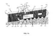
- FIG. 1One exemplary embodiment 100 of an antenna component for use in a mobile radio device is presented in FIG. 1 , showing an end portion of the mobile device housing 102 .
- the housing 102(also referred to as metal chassis or enclosure) is fabricated from a metal or alloy (such as aluminum alloy) and is configured to support a display element 104 .
- the housing 102comprises a sleeve-type form, and is manufactured by extrusion.
- the chassis 102comprises a metal frame structure with an opening to accommodate the display 104 .
- a variety of other manufacturing methodsmay be used consistent with the invention including, but not limited to, stamping, milling, and casting.
- the display 104comprises a display-only device configured only to display content or data.
- the display 104is a touch screen display (e.g., capacitive or other technology) that allows for user input into the device via the display 104 .
- the display 104may comprise, for example, a liquid crystal display (LCD), light-emitting diode (LED) display, organic light emitting diode (OLED) display, or TFT-based device. It is appreciated by those skilled in the art that methodologies of the present invention are equally applicable to any future display technology, provided the display module is generally mechanically compatible with configurations such as those described in FIG. 1-FIG . 2 C.
- the antenna assembly of the embodiment of FIG. 1further comprises a rectangular radiator element 108 configured to be fitted against a side surface 106 of the enclosure 102 .
- the side 106can be any of the top, bottom, left, right, front, or back surfaces of the mobile radio device.
- modern portable devicesare manufactured such that their thickness 111 is much smaller than the, length or the width of the device housing.
- the radiator element of the illustrated embodimentis fabricated to have an elongated shape such that the length 110 is greater than the width 112 , when disposed along a side surface (e.g., left, right, top, bottom).
- an openingis fabricated in the device enclosure.
- the opening 114extends through the side surface 106 and serves to pass through a feed conductor 116 from a feed engine that is a part of the device RE section (not shown), located on the inside of the device.
- the openingis fabricated proximate to the radiator feed point as described in detail below.
- the antenna assembly of FIG. 1further comprises a dielectric antenna cover 118 that is installed directly above the radiator element 108 .
- the cover 118is configured to provide electrical insulation for the radiator from the outside environment, particularly to prevent direct contact between a user hand and the radiator during device use (which is often detrimental to antenna operation).
- the cover 118is fabricated from any suitable dielectric material (e.g. plastic or glass).
- the cover 118is attached by a variety of suitable means: adhesive, press-fit, snap-in with support of additional retaining members as described below.
- the cover 118is fabricated from a durable oxide or glass (e.g. Zirconium dioxide ZrO 2 , (also referred to as “zirconia”), or Gorilla® Glass, manufactured by Dow Corning) and is welded (such as via a ultrasonic-welding (USW) technique) onto the device body.
- a durable oxide or glasse.g. Zirconium dioxide ZrO 2 , (also referred to as “zirconia”), or Gorilla® Glass, manufactured by Dow Corning
- USWultrasonic-welding
- Other attachment methodsmay be used including but not limited to adhesive, snap-fit, press-fit, heat staking, etc.
- the covercomprises a non-conductive film, or non-conductive paint bonded onto one or more exterior surfaces of the radiator element(s).
- the detailed structure of an exemplary embodiment 120 of radiator element 108 configured for mounting in a radio deviceis presented in FIG. 1A .
- the radiator element 108comprises a conductive coating 129 disposed on a rigid substrate 141 , such as a PCB fabricated from a dielectric material (e.g., FR-4). Other suitable materials, such as glass, ceramic, air are useable as well.
- a conductive layeris disposed on the opposing surface of the substrate, thereby forming a portion of a ground plane.
- the radiator elementis fabricated as a flex circuit (either a single-sided, or double-sided) that is mounted on a rigid support element.
- the conductive coating 129is shaped to form a radiator structure 130 , which includes a first portion 122 and a second portion 124 , and is coupled to the feed conductor 116 at a feed point 126 .
- the second portion 124is coupled to the feed point 126 via a conductive element 128 , which acts as a transmission line coupling antenna radiator to chassis modes.
- the first portion 122 and the second portion 124are connected via a coupling element 125 .
- the transmission line element 128is configured to form a finger-like projection into the first portion 122 , thereby forming two narrow slots 131 , 133 , one on each side of the transmission line 128 .
- the radiator 108further includes a several ground clearance portions ( 135 , 137 , 139 ), which are used to form a loop structure and to tune the antenna to desired specifications (e.g., frequency, bandwidth, etc).
- the feed conductor 116 of exemplary embodiment of FIG. 1Ais a coaxial cable, comprising a center conductor 140 , connected to the feed point 126 , a shield 142 , and an exterior insulator 146 .
- a portion of the feed conductor 116is routed lengthwise along the radiator PCB 108 .
- the shield 148is connected to the radiator ground plane 129 at one or more locations 148 , as shown in FIG. 1A .
- the other end of the feed conductor 116is connected to an appropriate feed port (not shown) of the RF section of the device electronics. In one variant this connection is effected via a radio frequency connector.
- a lumped reactive component 152(e.g. inductive L or capacitive C) is coupled across the second portion 124 in order to adjust radiator electrical length.
- a lumped reactive component 152e.g. inductive L or capacitive C
- capacitor configurationsare useable in the embodiment 120 , including but not limited to, a single or multiple discrete capacitors (e.g., plastic film, mica, glass, or paper), or chip capacitors.
- myriad inductor configurationse.g., air coil, straight wire conductor, or toroid core may be used with the invention.
- the radiating element 108further comprises a ground point 136 that is configured to couple the radiating element 108 to the device ground (e.g., housing/chassis).
- the radiating element 108is affixed to the device via a conductive sponge at the ground coupling point 136 and to the feed cable via a solder joint at the feed point 126 .
- both above connectionsare effected via solder joints.
- both connectionsare effected via a conductive sponge.
- Other electrical coupling methodsare useable with embodiments of the invention including, but not limited to, c-clip, pogo pin, etc.
- a suitable adhesive or mechanical retaining meansmay be used if desired to affix the radiating element to the device housing.
- the radiator elementis approximately 10 mm (0.3 in) in width and 50 mm (2 in) in length. It will be appreciated by those skilled in the art that the above antenna sizes are exemplary and are adjusted based on the actual size of the device and its operating band. In one variant, the electrical size of the antenna is adjusted by the use of a lumped reactive component 152 .
- a dielectric screen 156is placed against the radiating element 108 to electrically isolate the conductive structure 140 and the feed point from the device metal enclosure/chassis 102 .
- the dielectric screen 156comprises an opening 158 that corresponds to the location and the size of the ground point 136 , and is configured to permit electrical contact between the ground point and the metal chassis.
- a similar opening(not shown) is fabricates at the location of the feed point.
- the dielectric screencomprises a plastic film or non-conducting spray, although it will be recognized by those of ordinary skill given the present disclosure that other materials may be used with equal success.
- FIG. 1Cshows an interior view of the radiating element 108 assembly installed into the housing 102 .
- the radiating elementis mounted against the housing side 106 , with the dielectric screen 156 fitted in-between.
- a channel or a groove 162is fabricated in the side 106 .
- the groove 162is configured to recess the conductor flush with the outer surface of the enclosure/chassis, while permitting access to the radiator feed point. This configuration decreases the gap between the radiator element 108 and the housing side 106 , thereby advantageously reducing thickness of the antenna assembly.
- a suitable adhesive or mechanical retaining meansmay be used if desired to affix the radiating element to the device housing.
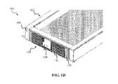
- FIG. 1Dshows an exterior view of the radiating element 108 assembly installed into the housing 102 .
- the radiating element 108is mounted against the housing side 106 , with the dielectric screen 156 fitted in between.
- FIG. 1Dreveals the conductive coating 143 forming a portion of the ground plane of the radiating element, described above with respect to FIG. 1A .
- the conductive coating 143features a ground clearance element 168 approximately corresponding to the location and the size of the ground clearance elements 135 , 137 and the second portion 124 of the radiator, disposed on the opposite side of the radiator element 108 .
- the exemplary antenna radiator illustrated in FIG. 1A through 1Duses the radiator structure that is configured to form a coupled loop chassis excited resonator.
- the feed configuration described abovewherein a portion of the feed conductor is routed along the dimension 110 of the radiator, cooperates to form the coupled loop resonator.
- a small gap between the loop antenna and the chassisfacilitates electromagnetic coupling between the antenna radiator and the chassis.
- At least a portion of the metal chassis 102forms a part of an antenna resonance structure, thereby improving antenna performance (particularly efficiency and bandwidth).
- the gapis on the order of 0.1 mm, although other values may be used depending on the application.
- the transmission line 128forms a part of loop resonator and helps in coupling the chassis modes.
- the length of the transmission linecontrols coupling and feed efficiency including, e.g., how efficiently the feed energy is transferred to the housing/chassis.
- the optimal length of the transmission lineis determined based, at least in part on, the frequency of operation: e.g., the required length of transmission line for operating band at approximately 1 GHz is twice the length of the transmission line required for the antenna operating at approximately 2 GHz band.
- the use of a single point grounding configuration of the radiator to the metal enclosure/chassis (at the ground point 136 )facilitates formation of a chassis excited antenna structure that is efficient, simple to manufacture, and is lower in cost compared to the existing solutions (such as conventional inverted planar inverted-F (PTA) or monopole antennas). Additionally, when using a planar configuration of the loop antenna, the thickness of the portable communication device may be reduced substantially, which often critical for satisfying consumer demand for more compact communication devices.
- the ground point of the radiator 108is coupled directly to the metal housing (chassis) that is in turn is coupled to ground of the mobile device RF section (not shown).
- the location of the grounding pointis determined based on the antenna design parameters such as dimension of the antenna loop element, and desired frequency band of operation.
- the antenna resonant frequencyis further a function of the device dimension. Therefore, the electrical size of the loop antenna (and hence the location of the grounding point) depends on the placement of the loop. In one variant, the electrical size of the loop PCB is about 50 mm for the lower band radiator (and is located on the bottom side of the device enclosure), and about 30 mm for the upper band radiator (and is located on the top side of the device enclosure).
- the dimension(s) of the loopmay need to be adjusted accordingly in order to match the desired frequency band of operation
- the length of the feed conductoris determined by a variety of design parameters for a specific device (e.g., enclosure dimensions, operating frequency band, etc.).
- the feed conductor 116is approximately 50 mm (2 in) in length, and it is adjusted according to device dimension(s), location of RF electronics section (on the main PCB) and antenna dimension(s) and placement.
- the antenna configuration described above with respect to FIGS. 1-1Dallows construction of an antenna that results in a very small space used within the device size: in effect, a ‘zero-volume’ antenna.
- Such small volume antennasadvantageously facilitate antenna placement in various locations on the device chassis, and expand the number of possible locations and orientations within the device.
- the use of the chassis coupling to aid antenna excitationallows modifying the size of loop antenna element required to support a particular frequency band.
- Antenna performanceis improved in the illustrated embodiments (compared to the existing solutions) largely because the radiator element(s) is/are placed outside the metallic chassis, while still being coupled to the chassis.
- the resonant frequency of the antennais controlled by (i) altering the size of the loop (either by increasing/decreasing the length of the radiator, or by adding series capacitor/inductor); and/or (ii) the coupling distance between the antenna and the metallic chassis.
- the placement of the antennais chosen based on the device specification, and accordingly the size of the loop is adjusted in accordance with antenna requirements.
- the radiating structure 130 and the ground point 138are position such that both faces the device enclosure/chassis. It is recognized by those skilled in the art that other implementations are suitable, such as one or both elements 130 , 138 facing outwards towards the cover 118 .
- a matching holeis fabricated in the substrate 141 to permit access to the feed center conductor 140 .
- the ground point 136is placed on the ground plane 143 , instead of the ground plane 129 .
- FIG. 1Eshows another embodiment of the antenna assembly of the invention that is specifically configured to fit into a top or a bottom side 184 of the portable device housing 188 .
- the housingcomprises a sleeve-like shape (e.g., with the top 184 and the bottom sides open).
- a metal support element 176is used to mount the antenna radiator element 180 .
- FIG. 1Eprovides a fully metallic chassis, and ensures rigidity of the device.
- the enclosure and the support elementare manufactured from the same material (e.g., aluminum alloy), thus simplifying manufacturing, reducing cost and allowing to achieve a seamless structure for the enclosure via decorative post processing processes.
- the device housingcomprises a metal enclosure with closed vertical sides (e.g., right, left, top and bottom), therefore, not requiring additional support elements, such as the support element 168 of FIG. 1D .
- the device display(not shown) is configured to fit within the cavity 192 formed on the upper surface of the device housing.
- An antenna cover 178is disposed above the radiator element 180 so as to provide isolation from the exterior influences.
- the support element 176is formed to fit precisely into the opening 184 of the housing and is attached to the housing via any suitable means including for example press fit, micro-welding, or fasteners (e.g. screws, rivets, etc.), or even suitable adhesives.
- the exterior surface 175 of the support element 176is shaped to receive the antenna radiator 180 .
- the support element 178further comprises an opening 194 that is designed to pass through the feed conductor 172 .
- the feed conductor 172is connected to the PCB 189 of the portable device and to the feed point (not shown) of the antenna radiator element 180 .
- the feed conductor, the radiator structure, and the ground coupling arrangementare configured similarly to the embodiments described above with respect to FIGS. 1A-1B .
- a portion of the feed conductor lengthis routed lengthwise along the dimension 174 of the antenna support element 176 : e.g., along an interior surface of the element 176 , or along the exterior surface.
- Matching groovesmay also be fabricated on the respective surface of the support element 168 to recess the feed conductor flush with the surface if desired.
- a portion of the feed conductor 172is routed along a lateral edge of the support element 178 .
- the opening 194is fabricated closer to that lateral edge.
- the radiating element 180is affixed to the chassis via a conductive sponge at the ground coupling point and to the feed cable via a solder joint at the feed point. In one variant, both couplings are effected via solder joints. Additionally or alternatively, a suitable adhesive or mechanical retaining means (e.g., snap fit, c-clip) may be used if desired.
- a suitable adhesive or mechanical retaining meanse.g., snap fit, c-clip
- the radiator cover 178is, in the illustrated embodiment, fabricated from any suitable dielectric material (e.g. plastic).
- the radiator cover 178is attached to the device housing by any of a variety of suitable means, such as: adhesive; press-fit, snap-in fit with support of additional retaining members 182 , etc.
- the radiator cover 178comprises a non-conductive film, laminate, or non-conductive paint bonded onto one or more of the exterior surfaces of the respective radiator element.
- a thin layer of dielectricis placed between the radiating element 180 , the coaxial cable 172 and the metal support 176 in order to prevent direct contact between the radiator and metal carrier in all but one location: the ground point.
- the insulator(not shown) has an opening that corresponds to the location and size of the ground point on the radiator element 180 , similarly to the embodiment described above with respect to FIG. 1A .
- the cover 178is fabricated from a durable oxide or glass (e.g. zirconia, or Gorilla® Glass manufactured by Dow Corning) and is welded (i.e., via a ultrasonic-welding (USW) technique) onto the device body.
- a durable oxide or glasse.g. zirconia, or Gorilla® Glass manufactured by Dow Corning
- USWultrasonic-welding
- Other attachment methodsare useable including but not limited to adhesive, snap-fit, press-fit, heat staking, etc.
- the antenna radiator element 180 , the feed conductor 172 , the metal support 176 , and the device enclosurecooperate to form a coupled loop resonator, thereby facilitating formation of the chassis excited antenna structure that is efficient, simple to manufacture and is lower cost compared to the existing solutions.
- antenna performance for the device of FIG. 1Eis improved compared to the existing implementations, largely because the radiator element is placed outside the metallic enclosure/chassis, while still being coupled to the chassis.
- the mobile devicecomprises a metal enclosure (or chassis) 202 having a width 204 , a length 212 , and a thickness (height) 211 .
- Two antenna elements 210 , 230are disposed onto two opposing sides 106 , 206 of the housing 202 , respectively.
- Each antenna elementis configured to operate in a separate frequency band (e.g., one antenna 210 in a lower frequency band, and one antenna 230 in an upper frequency band, although it will be appreciated that less or more and/or different bands may be formed based on varying configurations and/or numbers of antenna elements).
- a separate frequency bande.g., one antenna 210 in a lower frequency band, and one antenna 230 in an upper frequency band, although it will be appreciated that less or more and/or different bands may be formed based on varying configurations and/or numbers of antenna elements.
- Other configurationsmay be used consistent with the present invention, and will be recognized by those of ordinary skill given the present disclosure.
- both antennascan be configured to operate in the same frequency band, thereby providing diversity for MIMO operations.
- one antenna assemblyis configured to operate in an NFC-compliant frequency band, thereby enabling short range data exchange during, e.g., payment transactions.
- the illustrated antenna assembly 210comprises a rectangular antenna radiator 108 disposed on the side 106 of the enclosure, and coupled to the feed conductor 116 at a feed point (not shown).
- a pattern 107is fabricated on the side 106 of the housing.
- the feed conductor 116is fitted through an opening 114 fabricated in the housing side.
- a portion of the feed conductoris routed along the side 106 lengthwise, and is coupled to the radiator element 108 .
- An antenna cover 118is disposed directly on top of the radiator 108 so as to provide isolation for the radiator.
- the illustrated antenna assembly 230comprises a rectangular antenna radiator 238 disposed on the housing side 206 and coupled to feed conductor 236 at a feed point (not shown).
- the feed conductor 236is fitted through an opening (not shown) fabricated in the housing side 206 .
- a portion of the feed conductoris routed along the side 206 lengthwise, in a way that is similar to the feed conductor 116 , and is coupled to the radiator element 238 at a feed point.
- the radiating elements 108 , 238are affixed to the chassis via solder joints at the coupling points (ground and feed.
- the radiating elementsare affixed to the device via a conductive sponge at the ground coupling point and to the feed cable via a solder joint at the feed point.
- both connectionsare effected via a conductive sponge.
- Other electrical coupling methodsare useable with embodiments of the invention including, but not limited to, c-clip, pogo pin, etc.
- a suitable adhesive or mechanical retaining meansmay be used if desired to affix the radiating element to the device housing.
- the cover elements 118 , 240are in this embodiment also fabricated from any suitable dielectric material (e.g. plastic, glass, zirconia) and are attached to the device housing by a variety of suitable means, such as e.g., adhesive, press-fit, snap-in with support of additional retaining members (not shown), or the like.
- suitable meanssuch as e.g., adhesive, press-fit, snap-in with support of additional retaining members (not shown), or the like.
- the coversmay be fabricated from a non-conductive film, or non-conductive paint bonded onto one or more exterior surfaces of the radiator element(s) as discussed supra.
- a single, multi-feed transceivermay be used to provide feed to both antennas.
- each antennamay utilize a separate feed, wherein each antenna radiator directly is coupled to a separate feed port of the mobile radio device via a separate feed conductor (similar to that of the embodiment of FIG. 1A ) so as to enable operation of each antenna element in a separate frequency band (e.g., lower band, upper band).
- the device housing/chassis 102acts as a common ground for both antennas.
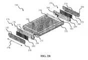
- FIG. 2Bshows another embodiment 250 of the mobile device of the invention, wherein two antenna components 160 , 258 are disposed on top and bottom sides of the mobile device housing 102 , respectively.
- Each antenna component 160 , 258is configured similarly to the antenna embodiment depicted in FIG. 1C , and operates in a separate frequency band (e.g., antenna 160 in an upper frequency band and antenna 258 in a lower frequency band).
- FIGS. 2A and 2Bshow two (2) radiating elements each, more radiating elements may be used (such as for the provision of more than two frequency bands, or to accommodate physical features or attributes of the host device).
- each embodimentcould be split into two sub-elements each (for a total of four sub-elements), and/or radiating elements could be placed both on the sides and on the top/bottom of the housing (in effect, combining the embodiments of FIGS. 2A and 2B ).
- the two radiating elements of each embodimentcould be split into two sub-elements each (for a total of four sub-elements), and/or radiating elements could be placed both on the sides and on the top/bottom of the housing (in effect, combining the embodiments of FIGS. 2A and 2B ).
- the antenna assemblies 160 , 258are specifically configured to fit in a substantially conformal fashion onto a top or a bottom side of the device housing 252 .
- the housing 252comprises a sleeve-like shape
- metal support elements 168 , 260are provided as the housing 252 comprises a sleeve-like shape.
- Support elements 168 , 260are shaped to fit precisely into the openings of the housing, and are attached to the housing via any suitable means, such as for example press fit, micro-welding, adhesives, or fasteners (e.g., screws or rivets).
- the outside surfaces of the support elements 168 , 260are shaped receive the antenna radiators 180 and 268 , respectively.
- the support elements 168 , 260include openings 170 , 264 , respectively, designed to fit the feed conductors 172 , 262 .
- the feed conductors 172 , 262are coupled to the main PCB 256 of the portable device.
- the device display(not shown) is configured to fit within the cavity 254 formed on the upper surface of the device housing.
- Antenna cover elements 178 , 266are disposed above the radiators 180 , 268 to provide isolation from the exterior influences.
- the radiating elements 180 , 268are affixed to the respective antenna support elements via solder joints at the coupling points (ground and feed).
- conductive sponge and suitable adhesive or mechanical retaining meanse.g., snap fit, press fit
- 160 , 258are configured in a non-conformal arrangement.
- cover elements 178 , 266may be fabricated from any suitable dielectric material (e.g., plastic, zirconia, or tough glass) and attached to the device housing by any of a variety of suitable means, such as e.g., adhesives, press-fit, snap-in with support of additional retaining members 182 , 270 , 272
- suitable meanssuch as e.g., adhesives, press-fit, snap-in with support of additional retaining members 182 , 270 , 272
- a portion of the feed conductoris routed along a lateral edge of the respective support element ( 168 , 268 ).
- opening 170 , 264are fabricated closer to that lateral edge.
- the phone housing or chassis 252acts as a common ground for both antennas in the illustrated embodiment.
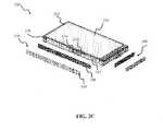
- a third embodiment 280 of the mobile deviceis presented in FIG. 2C , wherein the antenna assemblies 210 , 290 are disposed on the left and the bottom sides of the mobile device housing 202 , respectively.
- the device housing 202comprises a metal enclosure supporting one or more displays 254 .
- Each antenna element of FIG. 2Cis configured to operate in a separate frequency band (e.g., antenna 290 in a lower frequency band and antenna 210 in an upper frequency band).
- Other configurationse.g., more or less elements, different placement or orientation, etc.
- the antenna assemblies 210 , 290are constructed similarly to the antenna assembly 210 described above with respect to FIG. 2A .
- the device housing 202 of the exemplary implementation of FIG. 2Cis a metal enclosure with closed sides, therefore not requiring additional support element(s) (e.g., 168 ) to mount the antenna radiator(s).
- the lower frequency band(i.e., that associated with one of the two radiating elements operating at lower frequency) comprises a sub-GHz Global System for Mobile Communications (GSM) band (e.g., GSM710, GSM750, GSM850, GSM810, GSM900), while the higher band comprises a GSM1900, GSM1800, or PCS-1900 frequency band (e.g., 1.8 or 1.9 GHz).
- GSMGlobal System for Mobile Communications
- the low or high bandcomprises the Global Positioning System (GPS) frequency band
- the antennais used for receiving GPS position signals for decoding by e.g., an internal GPS receiver.
- GPSGlobal Positioning System
- a single upper band antenna assemblyoperates in both the GPS and the Bluetooth frequency bands.
- the high-bandcomprises a Wi-Fi (IEEE Std. 802.11) or Bluetooth frequency band (e.g., approximately 2.4 GHz), and the lower band comprises GSM1900, GSM1800, or PCS1900 frequency band.
- Wi-FiIEEE Std. 802.11
- Bluetooth frequency bande.g., approximately 2.4 GHz
- the lower bandcomprises GSM1900, GSM1800, or PCS1900 frequency band.
- two or more antennasconfigured in accordance with the principles of the present invention, operate in the same frequency band thus providing, inter alia, diversity for Multiple In Multiple Out (MIMO) or for Multiple In Single Out (MISO) applications.
- MIMOMultiple In Multiple Out
- MISOMultiple In Single Out
- one of the frequency bandscomprises a frequency band suitable for Near Field Communications applications, e.g., ISM 13.56 MHz band.
- LTE/LTE-Ae.g., 698 MHz-740 MHz, 900 MHz, 1800 MHz, and 2.5 GHz-2.6 GHz
- WWANe.g., 824 MHz-960 MHz, and 1710 MHz-2170 MHz
- WiMAX2.3, and 2.5 GHz
- a single radiating element and a single feedare configured provide a single feed solution that operates in two separate frequency bands.
- a single dual loop radiatorforms both frequency bands using a single fee point such that two feed lines (transmission lines 128 ) of different lengths configured to form two loops, which are joined together at a single diplexing point.
- the diplexing pointis, in turn, coupled to the port of the device via a feed conductor 116 .
- the frequency band composition given abovemay be modified as required by the particular application(s) desired.
- the present inventioncontemplates yet additional antenna structures within a common device (e.g., tri-band or quad-band) with one, two, three, four, or more separate antenna assemblies where sufficient space and separation exists.
- Each individual antenna assemblycan be further configured to operate in one or more frequency bands. Therefore, the number of antenna assemblies does not necessarily need to match the number of frequency bands.
- the inventionfurther contemplates using additional antenna elements for diversity/MIMO type of application.
- the location of the secondary antenna(s)can be chosen to have the desired level of pattern/polarization/spatial diversity.
- the antenna of the present inventioncan be used in combination with one or more other antenna types in a MIMO/SIMO configuration (i.e., a heterogeneous MIMO or SIMO array having multiple different types of antennas).
- An antenna assembly configured according to the exemplary embodiments of FIGS. 1-2Ccan advantageously be used to enable e.g., short-range communications in a portable wireless device, such as so-called Near-Field Communications (NFC) applications.
- NFCNear-Field Communications
- the NFC functionalityis used to exchange data during a contactless payment transaction. Any one of a plethora of such transactions can be conducted in this manner, including e.g., purchasing a movie ticket or a snack; Wi-Fi access at an NFC-enabled kiosk; downloading the URL for a movie trailer from a DVD retail display; purchasing the movie through an NFC-enabled set-top box in a premises environment; and/or purchasing a ticket to an event through an NFC-enabled promotional poster.
- the antenna assemblyis configured so as to enable data exchange over a desired distance; e.g., between 0.1 and 0.5 m.
- the exemplary antenna apparatuscomprises separate lower band and upper band antenna assemblies, which is suitable for a dual feed front end.
- the lower band assemblyis disposed along a bottom edge of the device, and the upper band assembly is disposed along a top edge of the device.
- the exemplary radiatorseach comprise a PCB coupled to a coaxial feed, and a single ground point per antenna.
- FIG. 3shows a plot of free-space return loss S 11 (in dB) as a function of frequency, measured with: (i) the lower-band antenna component 258 ; and (ii) the upper-band antenna assembly 170 , constructed in accordance with the embodiment depicted in FIG. 2B .
- Exemplary data for the lower ( 302 ) and the upper ( 304 ) frequency bandsshow a characteristic resonance structure between 820 MHz and 960 MHz in the lower band, and between 1710 MHz and 2170 MHz for the upper frequency band.
- Measurements of band-to-band isolationyield isolation values of about ⁇ 21 dB in the lower frequency band, and about ⁇ 29 dB in the upper frequency band.
- FIG. 4presents data regarding measured free-space efficiency for the same two antennas as described above with respect to FIG. 3 .
- the antenna efficiency (in dB)is defined as decimal logarithm of a ratio of radiated and input power:
- AntennaEfficiency10 ⁇ log 10 ⁇ ( Radiated ⁇ ⁇ Power Input ⁇ ⁇ Power ) Eqn . ⁇ ( 1 )
- An efficiency of zero (0) dBcorresponds to an ideal theoretical radiator, wherein all of the input power is radiated in the form of electromagnetic energy.
- the data in FIG. 4demonstrate that the lower-band antenna of the invention positioned at bottom side of the portable device achieves a total efficiency ( 402 ) between ⁇ 4.5 and ⁇ 3.75 dB over the exemplary frequency range between 820 and 960 MHz.
- the upped band data ( 404 ) in FIG. 4obtained with the upper-band antenna positioned along the top-side of the portable device, shows similar efficiency in the exemplary frequency range between 1710 and 2150 MHz.
- the exemplary antenna of FIG. 2Bis configured to operate in a lower exemplary frequency band from 700 MHz to 960 MHz, as well as the higher exemplary frequency band from 1710 MHz to 2170 MHz.
- This capabilityadvantageously allows operation of a portable computing device with a single antenna over several mobile frequency bands such as GSM710, GSM750, GSM850, GSM810, GSM1900, GSM1800, PCS-1900, as well as LTE/LTE-A and WiMAX (IEEE Std. 802.16) frequency bands.
- LTE/LTE-A and WiMAXIEEE Std. 802.16
- an antenna configurationthat uses the distributed antenna configuration as in the illustrated embodiments described herein allows for optimization of antenna operation in the lower frequency band independent of the upper band operation.
- the use of coupled loop chassis excited antenna structurereduces antenna size, particularly height, which in turn allows for thinner portable communication devices.
- a reduction in thicknesscan be a critical attribute for a mobile wireless device and its commercial popularity (even more so than other dimensions in some cases), in that thickness can make the difference between something fitting in a desired space (e.g., shirt pocket, travel bag side pocket, etc.) and not fitting.
- a near ‘zero volume’ antennais created.
- antenna complexity and costare reduced, while robustness and repeatability of mobile device antenna manufacturing and operation increase.
- the use of zirconia or tough glass materials for antenna covers in certain embodiments described hereinalso provides for an improved aesthetic appearance of the communications device and allows for decorative post-processing processes.
- a device that uses the antenna configuration as in the illustrated embodiments described hereinallows the use of a fully metal enclosure (or metal chassis) if desired.
- Such enclosures/chassisprovide a robust support for the display element, and create a device with a rigid mechanical construction (while also improving antenna operation). These features enable construction of thinner radio devices (compared to presently available solutions, described above) with large displays using fully metal enclosures.
- MIMOmultiple in multiple out
Landscapes
- Engineering & Computer Science (AREA)
- Computer Networks & Wireless Communication (AREA)
- Support Of Aerials (AREA)
- Waveguide Aerials (AREA)
- Details Of Aerials (AREA)
Abstract
Description
Claims (27)
Priority Applications (7)
| Application Number | Priority Date | Filing Date | Title |
|---|---|---|---|
| US13/026,078US8648752B2 (en) | 2011-02-11 | 2011-02-11 | Chassis-excited antenna apparatus and methods |
| CN201280008439.8ACN103348534B (en) | 2011-02-11 | 2012-01-24 | Underframe active antenna apparatus and method |
| PCT/IB2012/000330WO2012107835A2 (en) | 2011-02-11 | 2012-01-24 | Chassis-excited antenna apparatus and methods |
| KR1020137023693AKR101547746B1 (en) | 2011-02-11 | 2012-01-24 | Chassis-excited antenna component, antenna apparatus, and mobile communications device thereof |
| EP12744936.1AEP2673841A4 (en) | 2011-02-11 | 2012-01-24 | Chassis-excited antenna apparatus and methods |
| US14/177,093US9917346B2 (en) | 2011-02-11 | 2014-02-10 | Chassis-excited antenna apparatus and methods |
| US14/223,898US9673507B2 (en) | 2011-02-11 | 2014-03-24 | Chassis-excited antenna apparatus and methods |
Applications Claiming Priority (1)
| Application Number | Priority Date | Filing Date | Title |
|---|---|---|---|
| US13/026,078US8648752B2 (en) | 2011-02-11 | 2011-02-11 | Chassis-excited antenna apparatus and methods |
Related Child Applications (1)
| Application Number | Title | Priority Date | Filing Date |
|---|---|---|---|
| US14/177,093ContinuationUS9917346B2 (en) | 2011-02-11 | 2014-02-10 | Chassis-excited antenna apparatus and methods |
Publications (2)
| Publication Number | Publication Date |
|---|---|
| US20120206302A1 US20120206302A1 (en) | 2012-08-16 |
| US8648752B2true US8648752B2 (en) | 2014-02-11 |
Family
ID=46636476
Family Applications (2)
| Application Number | Title | Priority Date | Filing Date |
|---|---|---|---|
| US13/026,078Active - Reinstated2031-11-29US8648752B2 (en) | 2011-02-11 | 2011-02-11 | Chassis-excited antenna apparatus and methods |
| US14/177,093Active2031-03-29US9917346B2 (en) | 2011-02-11 | 2014-02-10 | Chassis-excited antenna apparatus and methods |
Family Applications After (1)
| Application Number | Title | Priority Date | Filing Date |
|---|---|---|---|
| US14/177,093Active2031-03-29US9917346B2 (en) | 2011-02-11 | 2014-02-10 | Chassis-excited antenna apparatus and methods |
Country Status (5)
| Country | Link |
|---|---|
| US (2) | US8648752B2 (en) |
| EP (1) | EP2673841A4 (en) |
| KR (1) | KR101547746B1 (en) |
| CN (1) | CN103348534B (en) |
| WO (1) | WO2012107835A2 (en) |
Cited By (44)
| Publication number | Priority date | Publication date | Assignee | Title |
|---|---|---|---|---|
| US20130044429A1 (en)* | 2010-06-15 | 2013-02-21 | Apple Inc. | Cooling arrangement for small form factor desktop computer |
| US20130342410A1 (en)* | 2012-06-20 | 2013-12-26 | Min-Chung Wu | Flexible Transmission Device and Communication Device Using the Same |
| US20140118204A1 (en)* | 2012-11-01 | 2014-05-01 | Nvidia Corporation | Antenna integrated with metal chassis |
| US20140184449A1 (en)* | 2012-12-27 | 2014-07-03 | Auden Techno.Corp | Antenna structure for using with a metal frame of a mobile phone |
| US20140347227A1 (en)* | 2013-05-24 | 2014-11-27 | Microsoft Corporation | Side face antenna for a computing device case |
| US20150077295A1 (en)* | 2008-11-06 | 2015-03-19 | Pong Research Corporation | Rf radiation redirection away from portable communication device user |
| US20150109168A1 (en)* | 2013-10-19 | 2015-04-23 | Auden Techno Corp. | Multi-frequency antenna and mobile communication device having the multi-frequency antenna |
| US20150116169A1 (en)* | 2013-10-31 | 2015-04-30 | Sony Corporation | MM Wave Antenna Array Integrated with Cellular Antenna |
| US20150155618A1 (en)* | 2011-06-10 | 2015-06-04 | Samsung Electronics Co., Ltd. | Antenna device for a portable terminal |
| US9178283B1 (en)* | 2012-09-17 | 2015-11-03 | Amazon Technologies, Inc. | Quad-slot antenna for dual band operation |
| US9196966B1 (en)* | 2012-09-17 | 2015-11-24 | Amazon Technologies, Inc. | Quad-slot antenna for dual band operation |
| US9231304B2 (en) | 2014-01-21 | 2016-01-05 | Nvidia Corporation | Wideband loop antenna and an electronic device including the same |
| US9287915B2 (en) | 2008-11-06 | 2016-03-15 | Antenna79, Inc. | Radiation redirecting elements for portable communication device |
| US9350410B2 (en) | 2008-11-06 | 2016-05-24 | Antenna79, Inc. | Protective cover for a wireless device |
| US9368862B2 (en) | 2014-01-21 | 2016-06-14 | Nvidia Corporation | Wideband antenna and an electronic device including the same |
| US9379445B2 (en) | 2014-02-14 | 2016-06-28 | Apple Inc. | Electronic device with satellite navigation system slot antennas |
| CN105811074A (en)* | 2016-01-27 | 2016-07-27 | 宇龙计算机通信科技(深圳)有限公司 | Antenna system and mobile terminal |
| US20160380335A1 (en)* | 2013-11-27 | 2016-12-29 | Samsung Electronics Co., Ltd. | Portable electronic device cover |
| US9543639B2 (en) | 2013-05-24 | 2017-01-10 | Microsoft Technology Licensing, Llc | Back face antenna in a computing device case |
| US9559425B2 (en) | 2014-03-20 | 2017-01-31 | Apple Inc. | Electronic device with slot antenna and proximity sensor |
| US9583838B2 (en) | 2014-03-20 | 2017-02-28 | Apple Inc. | Electronic device with indirectly fed slot antennas |
| US9595759B2 (en) | 2014-01-21 | 2017-03-14 | Nvidia Corporation | Single element dual-feed antennas and an electronic device including the same |
| US9660738B1 (en) | 2015-11-06 | 2017-05-23 | Microsoft Technology Licensing, Llc | Antenna with configurable shape/length |
| US9698466B2 (en) | 2013-05-24 | 2017-07-04 | Microsoft Technology Licensing, Llc | Radiating structure formed as a part of a metal computing device case |
| US9728858B2 (en) | 2014-04-24 | 2017-08-08 | Apple Inc. | Electronic devices with hybrid antennas |
| US20170264975A1 (en)* | 2016-03-11 | 2017-09-14 | Acer Incorporated | Communication device with narrow-ground-clearance antenna element |
| US20170302771A1 (en)* | 2016-04-19 | 2017-10-19 | Samsung Electronics Co., Ltd. | Electronic device including antenna |
| US9838060B2 (en) | 2011-11-02 | 2017-12-05 | Antenna79, Inc. | Protective cover for a wireless device |
| US20180108977A1 (en)* | 2014-10-08 | 2018-04-19 | Samsung Electronics Co., Ltd. | Electronic device and antenna device thereof |
| US20180366811A1 (en)* | 2017-06-16 | 2018-12-20 | Guangdong Oppo Mobile Telecommunications Corp., Lt D. | Housing, method for producing the same and mobile terminal |
| US10218052B2 (en) | 2015-05-12 | 2019-02-26 | Apple Inc. | Electronic device with tunable hybrid antennas |
| US10243279B2 (en) | 2016-02-29 | 2019-03-26 | Microsoft Technology Licensing, Llc | Slot antenna with radiator element |
| US10250289B2 (en) | 2016-09-06 | 2019-04-02 | Apple Inc. | Electronic device antennas with ground isolation |
| US10290946B2 (en) | 2016-09-23 | 2019-05-14 | Apple Inc. | Hybrid electronic device antennas having parasitic resonating elements |
| US10340592B2 (en) | 2016-07-29 | 2019-07-02 | Samsung Electronics Co., Ltd | Electronic device including multiple antennas |
| US10490881B2 (en) | 2016-03-10 | 2019-11-26 | Apple Inc. | Tuning circuits for hybrid electronic device antennas |
| US10498013B2 (en) | 2015-08-07 | 2019-12-03 | Microsoft Technology Licensing, Llc | Antenna arrangement for an electronic device |
| US20200036820A1 (en)* | 2015-08-13 | 2020-01-30 | Samsung Electronics Co., Ltd. | Antenna and electronic device including the same |
| US10581140B2 (en) | 2016-05-03 | 2020-03-03 | Samsung Electronics Co., Ltd. | Antenna module having metal frame antenna segment and electronic device including the same |
| US10608324B2 (en) | 2016-09-29 | 2020-03-31 | Samsung Electronics Co., Ltd. | Electronic device comprising antenna |
| US11145954B2 (en) | 2016-07-29 | 2021-10-12 | Hewlett-Packard Development Company, L.P. | Antenna for a communication device |
| US11251517B2 (en)* | 2019-12-26 | 2022-02-15 | Guangdong Oppo Mobile Telecommunications Corp., Ltd. | Antenna assembly and electronic device |
| US11374324B2 (en) | 2017-07-17 | 2022-06-28 | Hewlett-Packard Development Company, L.P. | Slotted patch antennas |
| US12199335B2 (en) | 2021-06-16 | 2025-01-14 | Samsung Electronics Co., Ltd. | Electronic device comprising an antenna |
Families Citing this family (115)
| Publication number | Priority date | Publication date | Assignee | Title |
|---|---|---|---|---|
| US8931505B2 (en) | 2010-06-16 | 2015-01-13 | Gregory E. HYLAND | Infrastructure monitoring devices, systems, and methods |
| US8559869B2 (en) | 2011-09-21 | 2013-10-15 | Daniel R. Ash, JR. | Smart channel selective repeater |
| KR101334812B1 (en) | 2011-04-14 | 2013-11-28 | 삼성전자주식회사 | Antenna device for portable terminal |
| FI127080B (en)* | 2011-06-10 | 2017-10-31 | Lite-On Mobile Oyj | An antenna arrangement and an electronic device |
| TWM420062U (en)* | 2011-06-22 | 2012-01-01 | Wistron Neweb Corp | Capacitive loop antenna and electronic device |
| US9291520B2 (en) | 2011-08-12 | 2016-03-22 | Mueller International, Llc | Fire hydrant leak detector |
| US9153856B2 (en)* | 2011-09-23 | 2015-10-06 | Apple Inc. | Embedded antenna structures |
| US9300033B2 (en) | 2011-10-21 | 2016-03-29 | Futurewei Technologies, Inc. | Wireless communication device with an antenna adjacent to an edge of the device |
| US9337528B2 (en)* | 2012-01-27 | 2016-05-10 | Blackberry Limited | Mobile wireless communications device including electrically conductive portable housing sections defining an antenna |
| JP2015518308A (en)* | 2012-03-20 | 2015-06-25 | トムソン ライセンシングThomson Licensing | ANTENNA DEVICE, SET-TOP BOX, AND COMMUNICATION METHOD |
| CN102737582B (en)* | 2012-04-06 | 2014-07-09 | 信利工业(汕尾)有限公司 | Termination point (TP) On/In Cell type organic electroluminescent display integrated with near field communication (NFC) antenna |
| TW201345050A (en)* | 2012-04-27 | 2013-11-01 | Univ Nat Taiwan Science Tech | Dual band antenna with circular polarization |
| US20130319866A1 (en) | 2012-05-29 | 2013-12-05 | Lucy Elizabeth Browning | Anodized films |
| US10283281B2 (en)* | 2012-08-15 | 2019-05-07 | Nokia Technologies Oy | Apparatus and methods for electrical energy harvesting and/or wireless communication |
| JP5670976B2 (en)* | 2012-09-18 | 2015-02-18 | 株式会社東芝 | Communication device |
| KR102013588B1 (en) | 2012-09-19 | 2019-08-23 | 엘지전자 주식회사 | Mobile terminal |
| TWI514663B (en)* | 2012-10-18 | 2015-12-21 | Asustek Comp Inc | Wireless communication apparatus and antenna system thereof |
| US9551758B2 (en) | 2012-12-27 | 2017-01-24 | Duracell U.S. Operations, Inc. | Remote sensing of remaining battery capacity using on-battery circuitry |
| TWI581509B (en)* | 2013-02-20 | 2017-05-01 | 群邁通訊股份有限公司 | Antenna assembly and portable electronic device having same |
| US9196952B2 (en)* | 2013-03-15 | 2015-11-24 | Qualcomm Incorporated | Multipurpose antenna |
| CN103219585B (en)* | 2013-03-22 | 2016-01-27 | 瑞声精密制造科技(常州)有限公司 | Antenna modules and apply the mobile terminal of this antenna modules |
| US9478850B2 (en)* | 2013-05-23 | 2016-10-25 | Duracell U.S. Operations, Inc. | Omni-directional antenna for a cylindrical body |
| US9726763B2 (en) | 2013-06-21 | 2017-08-08 | Duracell U.S. Operations, Inc. | Systems and methods for remotely determining a battery characteristic |
| US8954122B2 (en)* | 2013-07-03 | 2015-02-10 | BluFlux RF Technologies, LLC | Electronic device case with antenna |
| US20150009075A1 (en)* | 2013-07-05 | 2015-01-08 | Sony Corporation | Orthogonal multi-antennas for mobile handsets based on characteristic mode manipulation |
| CN203481374U (en)* | 2013-07-11 | 2014-03-12 | 中兴通讯股份有限公司 | Terminal |
| WO2015033498A1 (en) | 2013-09-03 | 2015-03-12 | ソニー株式会社 | Portable terminal |
| WO2015044527A1 (en)* | 2013-09-27 | 2015-04-02 | Nokia Technologies Oy | Transmission line structure and method of attaching transmission line structure to conductive body |
| CN103606742B (en)* | 2013-10-18 | 2016-06-08 | 上海安费诺永亿通讯电子有限公司 | A kind of composite antenna for handset terminal |
| CN203589216U (en)* | 2013-10-18 | 2014-05-07 | 上海安费诺永亿通讯电子有限公司 | Multiplex antenna capable of integrating diversity reception, GPS communication and WIFI communication |
| US20150116161A1 (en)* | 2013-10-28 | 2015-04-30 | Skycross, Inc. | Antenna structures and methods thereof for determining a frequency offset based on a signal magnitude measurement |
| CN104701598A (en)* | 2013-12-06 | 2015-06-10 | 华为终端有限公司 | Terminal with multimode antennas |
| KR101544698B1 (en)* | 2013-12-23 | 2015-08-17 | 주식회사 이엠따블유 | Intenna |
| US10468751B2 (en) | 2014-02-26 | 2019-11-05 | Galtronics Usa, Inc. | Multi-feed antenna assembly |
| KR102143103B1 (en)* | 2014-04-16 | 2020-08-10 | 삼성전자주식회사 | Antenna using Components of Electronic Device |
| US9882250B2 (en) | 2014-05-30 | 2018-01-30 | Duracell U.S. Operations, Inc. | Indicator circuit decoupled from a ground plane |
| KR102151425B1 (en)* | 2014-08-05 | 2020-09-03 | 삼성전자주식회사 | Antenna device |
| US9673513B2 (en)* | 2014-08-25 | 2017-06-06 | Samsung Electro-Mechanics Co., Ltd. | Radiator frame having antenna pattern embedded therein and electronic device including the same |
| DE102015115574A1 (en)* | 2014-11-13 | 2016-05-19 | Samsung Electronics Co., Ltd. | Near field communication chip embedded in a portable electronic device and portable electronic device |
| US9397727B1 (en)* | 2014-12-11 | 2016-07-19 | Amazon Technologies, Inc. | Slot antenna and NFC antenna in an electronic device |
| US20160294061A1 (en)* | 2015-03-30 | 2016-10-06 | Microsoft Technology Licensing, Llc | Integrated Antenna Structure |
| KR20160129336A (en)* | 2015-04-30 | 2016-11-09 | 엘지전자 주식회사 | Mobile terminal |
| US20160336644A1 (en)* | 2015-05-13 | 2016-11-17 | Chiun Mai Communication Systems, Inc. | Antenna structure and wireless communication device using the same |
| CN105098348B (en)* | 2015-05-22 | 2018-09-25 | 深圳富泰宏精密工业有限公司 | Shell, the electronic device and preparation method thereof using the shell |
| CN105244608A (en)* | 2015-07-27 | 2016-01-13 | 禾邦电子(苏州)有限公司 | Antenna and electronic equipment with antennas |
| CN105098330B (en)* | 2015-08-04 | 2018-08-21 | 青岛海信移动通信技术股份有限公司 | Mobile terminal antenna and mobile terminal |
| KR20170022442A (en) | 2015-08-20 | 2017-03-02 | 엘지전자 주식회사 | Mobile terminal |
| US10297875B2 (en) | 2015-09-01 | 2019-05-21 | Duracell U.S. Operations, Inc. | Battery including an on-cell indicator |
| WO2017058177A1 (en)* | 2015-09-29 | 2017-04-06 | Hewlett-Packard Development Company, L.P. | Coupled slot antennas |
| TWI577082B (en)* | 2015-10-08 | 2017-04-01 | 宏碁股份有限公司 | Communication device |
| US10158164B2 (en)* | 2015-10-30 | 2018-12-18 | Essential Products, Inc. | Handheld mobile device with hidden antenna formed of metal injection molded substrate |
| AU2016353613B2 (en) | 2015-11-13 | 2019-08-15 | Samsung Electronics Co., Ltd. | Antenna device and electronic device including the same |
| WO2017122905A1 (en)* | 2016-01-11 | 2017-07-20 | Samsung Electronics Co., Ltd. | Wireless communication device with leaky-wave phased array antenna |
| US10283857B2 (en) | 2016-02-12 | 2019-05-07 | Mueller International, Llc | Nozzle cap multi-band antenna assembly |
| US10305178B2 (en) | 2016-02-12 | 2019-05-28 | Mueller International, Llc | Nozzle cap multi-band antenna assembly |
| CN105573111A (en)* | 2016-02-17 | 2016-05-11 | 广东小天才科技有限公司 | Intelligent wearable device |
| US10686482B2 (en)* | 2016-02-26 | 2020-06-16 | Intel Corporation | Wi-gig signal radiation via ground plane subwavelength slit |
| US10615489B2 (en)* | 2016-06-08 | 2020-04-07 | Futurewei Technologies, Inc. | Wearable article apparatus and method with multiple antennas |
| US10431873B2 (en)* | 2016-06-20 | 2019-10-01 | Shure Acquisitions Holdings, Inc. | Diversity antenna for bodypack transmitter |
| TWI629832B (en)* | 2016-06-30 | 2018-07-11 | 和碩聯合科技股份有限公司 | Wearable electronic device |
| US10038234B2 (en)* | 2016-07-21 | 2018-07-31 | Chiun Mai Communication Systems, Inc. | Antenna structure and wireless communication device using same |
| US9905913B2 (en)* | 2016-07-21 | 2018-02-27 | Chiun Mai Communication Systems, Inc. | Antenna structure and wireless communication device using same |
| US10044097B2 (en)* | 2016-07-21 | 2018-08-07 | Chiun Mai Communication Systems, Inc. | Antenna structure and wireless communication device using same |
| US10186756B2 (en) | 2016-08-01 | 2019-01-22 | Intel IP Corporation | Antennas in electronic devices |
| US10367252B2 (en) | 2016-08-11 | 2019-07-30 | Apple Inc. | Broadband antenna |
| US10608293B2 (en) | 2016-11-01 | 2020-03-31 | Duracell U.S. Operations, Inc. | Dual sided reusable battery indicator |
| US10818979B2 (en) | 2016-11-01 | 2020-10-27 | Duracell U.S. Operations, Inc. | Single sided reusable battery indicator |
| US10483634B2 (en) | 2016-11-01 | 2019-11-19 | Duracell U.S. Operations, Inc. | Positive battery terminal antenna ground plane |
| US10151802B2 (en) | 2016-11-01 | 2018-12-11 | Duracell U.S. Operations, Inc. | Reusable battery indicator with electrical lock and key |
| US11024891B2 (en) | 2016-11-01 | 2021-06-01 | Duracell U.S. Operations, Inc. | Reusable battery indicator with lock and key mechanism |
| US10135122B2 (en)* | 2016-11-29 | 2018-11-20 | AMI Research & Development, LLC | Super directive array of volumetric antenna elements for wireless device applications |
| CN106785349B (en)* | 2016-12-15 | 2019-09-17 | 奇酷互联网络科技(深圳)有限公司 | Mobile terminal and its antenna assembly |
| WO2018126247A2 (en) | 2017-01-02 | 2018-07-05 | Mojoose, Inc. | Automatic signal strength indicator and automatic antenna switch |
| US10476135B2 (en) | 2017-06-23 | 2019-11-12 | Arlo Technologies, Inc. | Portable electronic device with embedded antenna |
| CN107658557B (en)* | 2017-09-14 | 2020-10-27 | 哈尔滨工程大学 | A miniaturized three-dimensional multi-frequency microstrip antenna |
| US10455065B2 (en)* | 2017-09-29 | 2019-10-22 | Lg Electronics Inc. | Mobile terminal |
| FR3076669B1 (en)* | 2018-01-11 | 2020-10-09 | Schneider Electric Ind Sas | WIRELESS COMMUNICATING ELECTRICAL DEVICE AND ELECTRICAL CABINET INCLUDING THIS ELECTRICAL DEVICE |
| CN110034402B (en)* | 2018-01-11 | 2021-11-23 | 深圳富泰宏精密工业有限公司 | Antenna structure and wireless communication device with same |
| DE102018204204A1 (en)* | 2018-03-20 | 2019-09-26 | Geze Gmbh | Wireless component of a fire detection system or a fire detection system |
| US10306029B1 (en) | 2018-04-05 | 2019-05-28 | Lg Electronics Inc. | Mobile terminal |
| WO2019194805A1 (en) | 2018-04-05 | 2019-10-10 | Hewlett-Packard Development Company, L.P. | Patch antennas with excitation radiator feeds |
| DE102018109671A1 (en)* | 2018-04-23 | 2019-10-24 | HELLA GmbH & Co. KGaA | Radio key with a loop antenna |
| JP7130470B2 (en)* | 2018-06-29 | 2022-09-05 | シャープ株式会社 | wireless communication device |
| EP3794675B1 (en)* | 2018-06-29 | 2024-01-24 | Nokia Shanghai Bell Co., Ltd. | Multiband antenna structure |
| KR102139075B1 (en)* | 2018-07-17 | 2020-07-30 | (주)파트론 | Electronic device with slot antenna |
| CN108987943B (en)* | 2018-07-24 | 2021-04-06 | 维沃移动通信有限公司 | Millimeter wave wireless terminal equipment |
| JP7054741B2 (en)* | 2018-07-31 | 2022-04-14 | ソニーグループ株式会社 | Antenna frame for millimeter wave antenna |
| CN109088144B (en)* | 2018-08-23 | 2021-01-05 | 北京小米移动软件有限公司 | Antenna of mobile terminal and mobile terminal |
| US10859462B2 (en) | 2018-09-04 | 2020-12-08 | Mueller International, Llc | Hydrant cap leak detector with oriented sensor |
| CN110970710B (en)* | 2018-09-29 | 2022-08-12 | 荷兰移动驱动器公司 | Antenna structure and wireless communication device having the same |
| TWI688162B (en)* | 2018-11-23 | 2020-03-11 | 宏碁股份有限公司 | Multi-band antenna |
| GB201820102D0 (en)* | 2018-12-10 | 2019-01-23 | Smart Antenna Tech Limited | Compact LTE antenna arrangement |
| US11342656B2 (en)* | 2018-12-28 | 2022-05-24 | Mueller International, Llc | Nozzle cap encapsulated antenna system |
| US11473993B2 (en) | 2019-05-31 | 2022-10-18 | Mueller International, Llc | Hydrant nozzle cap |
| US11249177B2 (en)* | 2019-06-17 | 2022-02-15 | The Boeing Company | Transceiver assembly for detecting objects |
| KR102665787B1 (en)* | 2019-09-06 | 2024-05-14 | 삼성전자주식회사 | Antenna and electronic device including the same |
| US11876279B2 (en) | 2020-02-25 | 2024-01-16 | Microsoft Technology Licensing, Llc | Hybrid cavity mode antenna |
| US11075453B1 (en) | 2020-02-28 | 2021-07-27 | Globalfoundries U.S. Inc. | Microelectronics package with ultra-low-K dielectric region between stacked antenna elements |
| KR20230002669A (en) | 2020-04-14 | 2023-01-05 | 존스테크 인터내셔널 코포레이션 | Wireless (OTA: OVER THE AIR) chip test system |
| US11862838B2 (en)* | 2020-04-17 | 2024-01-02 | Apple Inc. | Electronic devices having wideband antennas |
| WO2021219195A1 (en)* | 2020-04-27 | 2021-11-04 | Huawei Technologies Co., Ltd. | Antenna arrangement and communication device |
| US11050144B1 (en)* | 2020-05-08 | 2021-06-29 | W. L. Gore & Associates, Inc. | Assembly with at least one antenna and a thermal insulation component |
| US11293968B2 (en)* | 2020-05-12 | 2022-04-05 | Johnstech International Corporation | Integrated circuit testing for integrated circuits with antennas |
| US11542690B2 (en) | 2020-05-14 | 2023-01-03 | Mueller International, Llc | Hydrant nozzle cap adapter |
| US11417951B2 (en) | 2020-09-01 | 2022-08-16 | Apple Inc. | Electronic devices having antennas that radiate through three-dimensionally curved cover layers |
| TWI763047B (en)* | 2020-09-21 | 2022-05-01 | 和碩聯合科技股份有限公司 | Electronic device and antenna module |
| US11837754B2 (en) | 2020-12-30 | 2023-12-05 | Duracell U.S. Operations, Inc. | Magnetic battery cell connection mechanism |
| US20210296774A1 (en)* | 2021-03-30 | 2021-09-23 | Google Llc | Integrated Cellular and Ultra-Wideband Antenna System for a Mobile Electronic Device |
| CN113725602A (en)* | 2021-09-09 | 2021-11-30 | 维沃移动通信有限公司 | Electronic device |
| US20230085660A1 (en)* | 2021-09-17 | 2023-03-23 | Zebra Technologies Corporation | Mobile Device Housing with Integrated Antenna Carrier |
| TWI797896B (en)* | 2021-12-17 | 2023-04-01 | 華碩電腦股份有限公司 | Antenna device |
| CN114512797B (en)* | 2022-04-01 | 2024-11-05 | Oppo广东移动通信有限公司 | Antenna device and electronic equipment |
| TWI841002B (en)* | 2022-10-17 | 2024-05-01 | 華碩電腦股份有限公司 | Antenna structure |
| US12244077B2 (en)* | 2022-11-03 | 2025-03-04 | Meta Platforms Technologies, Llc | Wide-band antenna with parasitic element |
| US12354078B1 (en)* | 2022-12-30 | 2025-07-08 | Block, Inc. | Systems and methods for communicating with NFC readers |
Citations (472)
| Publication number | Priority date | Publication date | Assignee | Title |
|---|---|---|---|---|
| GB239246A (en) | 1924-04-14 | 1926-02-26 | Walter Zipper | Improvements in rims with removable flanges for automobile vehicles and the like |
| US2745102A (en) | 1945-12-14 | 1956-05-08 | Norgorden Oscar | Antenna |
| US3938161A (en) | 1974-10-03 | 1976-02-10 | Ball Brothers Research Corporation | Microstrip antenna structure |
| US4004228A (en) | 1974-04-29 | 1977-01-18 | Integrated Electronics, Ltd. | Portable transmitter |
| US4028652A (en) | 1974-09-06 | 1977-06-07 | Murata Manufacturing Co., Ltd. | Dielectric resonator and microwave filter using the same |
| US4031468A (en) | 1976-05-04 | 1977-06-21 | Reach Electronics, Inc. | Receiver mount |
| US4054874A (en) | 1975-06-11 | 1977-10-18 | Hughes Aircraft Company | Microstrip-dipole antenna elements and arrays thereof |
| US4069483A (en) | 1976-11-10 | 1978-01-17 | The United States Of America As Represented By The Secretary Of The Navy | Coupled fed magnetic microstrip dipole antenna |
| US4123758A (en) | 1976-02-27 | 1978-10-31 | Sumitomo Electric Industries, Ltd. | Disc antenna |
| US4123756A (en) | 1976-09-24 | 1978-10-31 | Nippon Electric Co., Ltd. | Built-in miniature radio antenna |
| US4131893A (en) | 1977-04-01 | 1978-12-26 | Ball Corporation | Microstrip radiator with folded resonant cavity |
| US4201960A (en) | 1978-05-24 | 1980-05-06 | Motorola, Inc. | Method for automatically matching a radio frequency transmitter to an antenna |
| US4255729A (en) | 1978-05-13 | 1981-03-10 | Oki Electric Industry Co., Ltd. | High frequency filter |
| US4313121A (en) | 1980-03-13 | 1982-01-26 | The United States Of America As Represented By The Secretary Of The Army | Compact monopole antenna with structured top load |
| US4356492A (en) | 1981-01-26 | 1982-10-26 | The United States Of America As Represented By The Secretary Of The Navy | Multi-band single-feed microstrip antenna system |
| US4370657A (en) | 1981-03-09 | 1983-01-25 | The United States Of America As Represented By The Secretary Of The Navy | Electrically end coupled parasitic microstrip antennas |
| US4423396A (en) | 1980-09-30 | 1983-12-27 | Matsushita Electric Industrial Company, Limited | Bandpass filter for UHF band |
| US4431977A (en) | 1982-02-16 | 1984-02-14 | Motorola, Inc. | Ceramic bandpass filter |
| US4546357A (en) | 1983-04-11 | 1985-10-08 | The Singer Company | Furniture antenna system |
| US4559508A (en) | 1983-02-10 | 1985-12-17 | Murata Manufacturing Co., Ltd. | Distribution constant filter with suppression of TE11 resonance mode |
| FR2553584B1 (en) | 1983-10-13 | 1986-04-04 | Applic Rech Electronique | HALF-LOOP ANTENNA FOR LAND VEHICLE |
| US4625212A (en) | 1983-03-19 | 1986-11-25 | Nec Corporation | Double loop antenna for use in connection to a miniature radio receiver |
| EP0208424A1 (en) | 1985-06-11 | 1987-01-14 | Matsushita Electric Industrial Co., Ltd. | Dielectric filter with a quarter wavelength coaxial resonator |
| US4652889A (en) | 1983-12-13 | 1987-03-24 | Thomson-Csf | Plane periodic antenna |
| US4661992A (en) | 1985-07-31 | 1987-04-28 | Motorola Inc. | Switchless external antenna connector for portable radios |
| US4692726A (en) | 1986-07-25 | 1987-09-08 | Motorola, Inc. | Multiple resonator dielectric filter |
| US4703291A (en) | 1985-03-13 | 1987-10-27 | Murata Manufacturing Co., Ltd. | Dielectric filter for use in a microwave integrated circuit |
| US4706050A (en) | 1984-09-22 | 1987-11-10 | Smiths Industries Public Limited Company | Microstrip devices |
| US4716391A (en) | 1986-07-25 | 1987-12-29 | Motorola, Inc. | Multiple resonator component-mountable filter |
| US4740765A (en) | 1985-09-30 | 1988-04-26 | Murata Manufacturing Co., Ltd. | Dielectric filter |
| US4742562A (en) | 1984-09-27 | 1988-05-03 | Motorola, Inc. | Single-block dual-passband ceramic filter useable with a transceiver |
| US4761624A (en) | 1986-08-08 | 1988-08-02 | Alps Electric Co., Ltd. | Microwave band-pass filter |
| US4800392A (en) | 1987-01-08 | 1989-01-24 | Motorola, Inc. | Integral laminar antenna and radio housing |
| US4800348A (en) | 1987-08-03 | 1989-01-24 | Motorola, Inc. | Adjustable electronic filter and method of tuning same |
| US4821006A (en) | 1987-01-17 | 1989-04-11 | Murata Manufacturing Co., Ltd. | Dielectric resonator apparatus |
| US4823098A (en) | 1988-06-14 | 1989-04-18 | Motorola, Inc. | Monolithic ceramic filter with bandstop function |
| US4827266A (en) | 1985-02-26 | 1989-05-02 | Mitsubishi Denki Kabushiki Kaisha | Antenna with lumped reactive matching elements between radiator and groundplate |
| US4862181A (en) | 1986-10-31 | 1989-08-29 | Motorola, Inc. | Miniature integral antenna-radio apparatus |
| US4879533A (en) | 1988-04-01 | 1989-11-07 | Motorola, Inc. | Surface mount filter with integral transmission line connection |
| US4896124A (en) | 1988-10-31 | 1990-01-23 | Motorola, Inc. | Ceramic filter having integral phase shifting network |
| EP0376643A2 (en) | 1988-12-27 | 1990-07-04 | Harada Industry Co., Ltd. | Flat-plate antenna for use in mobile communications |
| US4954796A (en) | 1986-07-25 | 1990-09-04 | Motorola, Inc. | Multiple resonator dielectric filter |
| US4965537A (en) | 1988-06-06 | 1990-10-23 | Motorola Inc. | Tuneless monolithic ceramic filter manufactured by using an art-work mask process |
| US4977383A (en) | 1988-10-27 | 1990-12-11 | Lk-Products Oy | Resonator structure |
| US4980694A (en) | 1989-04-14 | 1990-12-25 | Goldstar Products Company, Limited | Portable communication apparatus with folded-slot edge-congruent antenna |
| EP0339822A3 (en) | 1988-04-25 | 1991-01-02 | Gec Ferranti Defence Systems Limited | Transceiver testing apparatus |
| US5017932A (en) | 1988-11-04 | 1991-05-21 | Kokusai Electric Co., Ltd. | Miniature antenna |
| US5047739A (en) | 1987-11-20 | 1991-09-10 | Lk-Products Oy | Transmission line resonator |
| US5053786A (en) | 1982-01-28 | 1991-10-01 | General Instrument Corporation | Broadband directional antenna |
| US5097236A (en) | 1989-05-02 | 1992-03-17 | Murata Manufacturing Co., Ltd. | Parallel connection multi-stage band-pass filter |
| US5103197A (en) | 1989-06-09 | 1992-04-07 | Lk-Products Oy | Ceramic band-pass filter |
| US5109536A (en) | 1989-10-27 | 1992-04-28 | Motorola, Inc. | Single-block filter for antenna duplexing and antenna-summed diversity |
| US5155493A (en) | 1990-08-28 | 1992-10-13 | The United States Of America As Represented By The Secretary Of The Air Force | Tape type microstrip patch antenna |
| US5157363A (en) | 1990-02-07 | 1992-10-20 | Lk Products | Helical resonator filter with adjustable couplings |
| US5159303A (en) | 1990-05-04 | 1992-10-27 | Lk-Products | Temperature compensation in a helix resonator |
| US5166697A (en) | 1991-01-28 | 1992-11-24 | Lockheed Corporation | Complementary bowtie dipole-slot antenna |
| US5170173A (en) | 1992-04-27 | 1992-12-08 | Motorola, Inc. | Antenna coupling apparatus for cordless telephone |
| US5203021A (en) | 1990-10-22 | 1993-04-13 | Motorola Inc. | Transportable support assembly for transceiver |
| US5210510A (en) | 1990-02-07 | 1993-05-11 | Lk-Products Oy | Tunable helical resonator |
| US5210542A (en) | 1991-07-03 | 1993-05-11 | Ball Corporation | Microstrip patch antenna structure |
| US5220335A (en) | 1990-03-30 | 1993-06-15 | The United States Of America As Represented By The Administrator Of The National Aeronautics And Space Administration | Planar microstrip Yagi antenna array |
| US5229777A (en) | 1991-11-04 | 1993-07-20 | Doyle David W | Microstrap antenna |
| EP0279050B1 (en) | 1987-01-15 | 1993-08-04 | Ball Corporation | Three resonator parasitically coupled microstrip antenna array element |
| US5239279A (en) | 1991-04-12 | 1993-08-24 | Lk-Products Oy | Ceramic duplex filter |
| EP0278069B1 (en) | 1986-12-29 | 1993-08-25 | Ball Corporation | Near-isotropic low profile microstrip radiator especially suited for use as a mobile vehicle antenna |
| EP0332139B1 (en) | 1988-03-10 | 1993-09-15 | Kabushiki Kaisha Toyota Chuo Kenkyusho | Wide band antenna for mobile communications |
| GB2266997A (en) | 1992-05-07 | 1993-11-17 | Wallen Manufacturing Limited | Radio antenna. |
| US5278528A (en) | 1991-04-12 | 1994-01-11 | Lk-Products Oy | Air insulated high frequency filter with resonating rods |
| EP0400872B1 (en) | 1989-05-23 | 1994-01-19 | Harada Industry Co., Ltd. | A flat-plate antenna for use in mobile communications |
| US5281326A (en) | 1990-09-19 | 1994-01-25 | Lk-Products Oy | Method for coating a dielectric ceramic piece |
| US5298873A (en) | 1991-06-25 | 1994-03-29 | Lk-Products Oy | Adjustable resonator arrangement |
| US5302924A (en) | 1991-06-25 | 1994-04-12 | Lk-Products Oy | Temperature compensated dielectric filter |
| US5304968A (en) | 1991-10-31 | 1994-04-19 | Lk-Products Oy | Temperature compensated resonator |
| US5307036A (en) | 1989-06-09 | 1994-04-26 | Lk-Products Oy | Ceramic band-stop filter |
| US5319328A (en) | 1991-06-25 | 1994-06-07 | Lk-Products Oy | Dielectric filter |
| US5349315A (en) | 1991-06-25 | 1994-09-20 | Lk-Products Oy | Dielectric filter |
| US5349700A (en) | 1991-10-28 | 1994-09-20 | Bose Corporation | Antenna tuning system for operation over a predetermined frequency range |
| US5351023A (en) | 1992-04-21 | 1994-09-27 | Lk-Products Oy | Helix resonator |
| US5354463A (en) | 1991-06-25 | 1994-10-11 | Lk Products Oy | Dielectric filter |
| US5355142A (en) | 1991-10-15 | 1994-10-11 | Ball Corporation | Microstrip antenna structure suitable for use in mobile radio communications and method for making same |
| US5357262A (en) | 1991-12-10 | 1994-10-18 | Blaese Herbert R | Auxiliary antenna connector |
| US5363114A (en) | 1990-01-29 | 1994-11-08 | Shoemaker Kevin O | Planar serpentine antennas |
| US5369782A (en) | 1990-08-22 | 1994-11-29 | Mitsubishi Denki Kabushiki Kaisha | Radio relay system, including interference signal cancellation |
| US5382959A (en) | 1991-04-05 | 1995-01-17 | Ball Corporation | Broadband circular polarization antenna |
| US5386214A (en) | 1989-02-14 | 1995-01-31 | Fujitsu Limited | Electronic circuit device |
| US5387886A (en) | 1992-05-14 | 1995-02-07 | Lk-Products Oy | Duplex filter operating as a change-over switch |
| US5394162A (en) | 1993-03-18 | 1995-02-28 | Ford Motor Company | Low-loss RF coupler for testing a cellular telephone |
| US5408206A (en) | 1992-05-08 | 1995-04-18 | Lk-Products Oy | Resonator structure having a strip and groove serving as transmission line resonators |
| US5418508A (en) | 1992-11-23 | 1995-05-23 | Lk-Products Oy | Helix resonator filter |
| US5432489A (en) | 1992-03-09 | 1995-07-11 | Lk-Products Oy | Filter with strip lines |
| US5438697A (en) | 1992-04-23 | 1995-08-01 | M/A-Com, Inc. | Microstrip circuit assembly and components therefor |
| US5440315A (en) | 1994-01-24 | 1995-08-08 | Intermec Corporation | Antenna apparatus for capacitively coupling an antenna ground plane to a moveable antenna |
| US5442366A (en) | 1993-07-13 | 1995-08-15 | Ball Corporation | Raised patch antenna |
| US5444453A (en) | 1993-02-02 | 1995-08-22 | Ball Corporation | Microstrip antenna structure having an air gap and method of constructing same |
| EP0399975B1 (en) | 1989-05-22 | 1995-11-02 | Nokia Mobile Phones Ltd. | RF connector for the connection of a radiotelephone to an external antenna |
| US5467065A (en) | 1993-03-03 | 1995-11-14 | Lk-Products Oy | Filter having resonators coupled by a saw filter and a duplex filter formed therefrom |
| US5473295A (en) | 1990-07-06 | 1995-12-05 | Lk-Products Oy | Saw notch filter for improving stop-band attenuation of a duplex filter |
| US5506554A (en) | 1993-07-02 | 1996-04-09 | Lk-Products Oy | Dielectric filter with inductive coupling electrodes formed on an adjacent insulating layer |
| US5508668A (en) | 1993-04-08 | 1996-04-16 | Lk-Products Oy | Helix resonator filter with a coupling aperture extending from a side wall |
| US5510802A (en) | 1993-04-23 | 1996-04-23 | Murata Manufacturing Co., Ltd. | Surface-mountable antenna unit |
| EP0447218B1 (en) | 1990-03-15 | 1996-05-08 | Hughes Aircraft Company | Plural frequency patch antenna assembly |
| US5517683A (en) | 1995-01-18 | 1996-05-14 | Cycomm Corporation | Conformant compact portable cellular phone case system and connector |
| US5521561A (en) | 1994-02-09 | 1996-05-28 | Lk Products Oy | Arrangement for separating transmission and reception |
| US5532703A (en) | 1993-04-22 | 1996-07-02 | Valor Enterprises, Inc. | Antenna coupler for portable cellular telephones |
| US5541560A (en) | 1993-03-03 | 1996-07-30 | Lk-Products Oy | Selectable bandstop/bandpass filter with switches selecting the resonator coupling |
| US5541617A (en) | 1991-10-21 | 1996-07-30 | Connolly; Peter J. | Monolithic quadrifilar helix antenna |
| US5543764A (en) | 1993-03-03 | 1996-08-06 | Lk-Products Oy | Filter having an electromagnetically tunable transmission zero |
| US5550519A (en) | 1994-01-18 | 1996-08-27 | Lk-Products Oy | Dielectric resonator having a frequency tuning element extending into the resonator hole |
| US5557287A (en) | 1995-03-06 | 1996-09-17 | Motorola, Inc. | Self-latching antenna field coupler |
| US5557292A (en) | 1994-06-22 | 1996-09-17 | Space Systems/Loral, Inc. | Multiple band folding antenna |
| EP0615285A3 (en) | 1993-03-11 | 1996-09-18 | Csir | Mounting an electronic circuit on a substrate. |
| US5570071A (en) | 1990-05-04 | 1996-10-29 | Lk-Products Oy | Supporting of a helix resonator |
| FR2724274B1 (en) | 1994-09-07 | 1996-11-08 | Telediffusion Fse | FRAME ANTENNA, INSENSITIVE TO CAPACITIVE EFFECT, AND TRANSCEIVER DEVICE COMPRISING SUCH ANTENNA |
| US5585810A (en) | 1994-05-05 | 1996-12-17 | Murata Manufacturing Co., Ltd. | Antenna unit |
| US5585771A (en) | 1993-12-23 | 1996-12-17 | Lk-Products Oy | Helical resonator filter including short circuit stub tuning |
| US5589844A (en) | 1995-06-06 | 1996-12-31 | Flash Comm, Inc. | Automatic antenna tuner for low-cost mobile radio |
| US5594395A (en) | 1993-09-10 | 1997-01-14 | Lk-Products Oy | Diode tuned resonator filter |
| US5604471A (en) | 1994-03-15 | 1997-02-18 | Lk Products Oy | Resonator device including U-shaped coupling support element |
| EP0759646A1 (en) | 1995-08-07 | 1997-02-26 | Murata Manufacturing Co., Ltd. | Chip antenna |
| US5627502A (en) | 1994-01-26 | 1997-05-06 | Lk Products Oy | Resonator filter with variable tuning |
| US5649316A (en) | 1995-03-17 | 1997-07-15 | Elden, Inc. | In-vehicle antenna |
| US5668561A (en) | 1995-11-13 | 1997-09-16 | Motorola, Inc. | Antenna coupler |
| US5675301A (en) | 1994-05-26 | 1997-10-07 | Lk Products Oy | Dielectric filter having resonators aligned to effect zeros of the frequency response |
| US5689221A (en) | 1994-10-07 | 1997-11-18 | Lk Products Oy | Radio frequency filter comprising helix resonators |
| US5694135A (en) | 1995-12-18 | 1997-12-02 | Motorola, Inc. | Molded patch antenna having an embedded connector and method therefor |
| US5703600A (en) | 1996-05-08 | 1997-12-30 | Motorola, Inc. | Microstrip antenna with a parasitically coupled ground plane |
| US5709832A (en) | 1995-06-02 | 1998-01-20 | Ericsson Inc. | Method of manufacturing a printed antenna |
| US5711014A (en) | 1993-04-05 | 1998-01-20 | Crowley; Robert J. | Antenna transmission coupling arrangement |
| US5717368A (en) | 1993-09-10 | 1998-02-10 | Lk-Products Oy | Varactor tuned helical resonator for use with duplex filter |
| US5731749A (en) | 1995-05-03 | 1998-03-24 | Lk-Products Oy | Transmission line resonator filter with variable slot coupling and link coupling #10 |
| EP0831547A2 (en) | 1996-09-20 | 1998-03-25 | Murata Manufacturing Co., Ltd. | Microstrip antenna |
| US5734351A (en) | 1995-06-05 | 1998-03-31 | Lk-Products Oy | Double-action antenna |
| US5734305A (en) | 1995-03-22 | 1998-03-31 | Lk-Products Oy | Stepwise switched filter |
| US5734350A (en) | 1996-04-08 | 1998-03-31 | Xertex Technologies, Inc. | Microstrip wide band antenna |
| EP0637094B1 (en) | 1993-07-30 | 1998-04-08 | Matsushita Electric Industrial Co., Ltd. | Antenna for mobile communication |
| US5739735A (en) | 1995-03-22 | 1998-04-14 | Lk Products Oy | Filter with improved stop/pass ratio |
| US5742259A (en) | 1995-04-07 | 1998-04-21 | Lk-Products Oy | Resilient antenna structure and a method to manufacture it |
| US5757327A (en) | 1994-07-29 | 1998-05-26 | Mitsumi Electric Co., Ltd. | Antenna unit for use in navigation system |
| US5764190A (en) | 1996-07-15 | 1998-06-09 | The Hong Kong University Of Science & Technology | Capacitively loaded PIFA |
| US5768217A (en) | 1996-05-14 | 1998-06-16 | Casio Computer Co., Ltd. | Antennas and their making methods and electronic devices or timepieces with the antennas |
| US5767809A (en) | 1996-03-07 | 1998-06-16 | Industrial Technology Research Institute | OMNI-directional horizontally polarized Alford loop strip antenna |
| US5777581A (en) | 1995-12-07 | 1998-07-07 | Atlantic Aerospace Electronics Corporation | Tunable microstrip patch antennas |
| US5777585A (en) | 1995-04-08 | 1998-07-07 | Sony Corporation | Antenna coupling apparatus, external-antenna connecting apparatus, and onboard external-antenna connecting apparatus |
| EP0856907A1 (en) | 1997-02-04 | 1998-08-05 | Lucent Technologies Inc. | Aperture-coupled planar inverted-F antenna |
| US5793269A (en) | 1995-08-23 | 1998-08-11 | Lk-Products Oy | Stepwise regulated filter having a multiple-step switch |
| US5812094A (en) | 1996-04-02 | 1998-09-22 | Qualcomm Incorporated | Antenna coupler for a portable radiotelephone |
| US5815048A (en) | 1995-11-23 | 1998-09-29 | Lk-Products Oy | Switchable duplex filter |
| US5822705A (en) | 1995-09-26 | 1998-10-13 | Nokia Mobile Phones, Ltd. | Apparatus for connecting a radiotelephone to an external antenna |
| US5852421A (en) | 1996-04-02 | 1998-12-22 | Qualcomm Incorporated | Dual-band antenna coupler for a portable radiotelephone |
| US5861854A (en) | 1996-06-19 | 1999-01-19 | Murata Mfg. Co. Ltd. | Surface-mount antenna and a communication apparatus using the same |
| EP0751043B1 (en) | 1995-06-30 | 1999-01-20 | Nokia Mobile Phones Ltd. | Rack |
| US5874926A (en) | 1996-03-11 | 1999-02-23 | Murata Mfg Co. Ltd | Matching circuit and antenna apparatus |
| US5880697A (en) | 1996-09-25 | 1999-03-09 | Torrey Science Corporation | Low-profile multi-band antenna |
| US5886668A (en) | 1994-03-08 | 1999-03-23 | Hagenuk Telecom Gmbh | Hand-held transmitting and/or receiving apparatus |
| EP0766341B1 (en) | 1995-09-29 | 1999-03-31 | Murata Manufacturing Co., Ltd. | Surface mounting antenna and communication apparatus using the same antenna |
| US5892490A (en) | 1996-11-07 | 1999-04-06 | Murata Manufacturing Co., Ltd. | Meander line antenna |
| US5903820A (en) | 1995-04-07 | 1999-05-11 | Lk-Products Oy | Radio communications transceiver with integrated filter, antenna switch, directional coupler and active components |
| US5905475A (en) | 1995-04-05 | 1999-05-18 | Lk Products Oy | Antenna, particularly a mobile phone antenna, and a method to manufacture the antenna |
| US5920290A (en) | 1994-03-04 | 1999-07-06 | Flexcon Company Inc. | Resonant tag labels and method of making the same |
| US5926139A (en) | 1997-07-02 | 1999-07-20 | Lucent Technologies Inc. | Planar dual frequency band antenna |
| US5929813A (en) | 1998-01-09 | 1999-07-27 | Nokia Mobile Phones Limited | Antenna for mobile communications device |
| US5936583A (en) | 1992-09-30 | 1999-08-10 | Kabushiki Kaisha Toshiba | Portable radio communication device with wide bandwidth and improved antenna radiation efficiency |
| US5943016A (en) | 1995-12-07 | 1999-08-24 | Atlantic Aerospace Electronics, Corp. | Tunable microstrip patch antenna and feed network therefor |
| EP0942488A2 (en) | 1998-02-24 | 1999-09-15 | Murata Manufacturing Co., Ltd. | Antenna device and radio device comprising the same |
| US5959583A (en) | 1995-12-27 | 1999-09-28 | Qualcomm Incorporated | Antenna adapter |
| US5963180A (en) | 1996-03-29 | 1999-10-05 | Symmetricom, Inc. | Antenna system for radio signals in at least two spaced-apart frequency bands |
| US5966097A (en) | 1996-06-03 | 1999-10-12 | Mitsubishi Denki Kabushiki Kaisha | Antenna apparatus |
| US5970393A (en) | 1997-02-25 | 1999-10-19 | Polytechnic University | Integrated micro-strip antenna apparatus and a system utilizing the same for wireless communications for sensing and actuation purposes |
| US5977710A (en) | 1996-03-11 | 1999-11-02 | Nec Corporation | Patch antenna and method for making the same |
| US5986608A (en) | 1998-04-02 | 1999-11-16 | Lucent Technologies Inc. | Antenna coupler for portable telephone |
| US5986606A (en) | 1996-08-21 | 1999-11-16 | France Telecom | Planar printed-circuit antenna with short-circuited superimposed elements |
| US5990848A (en) | 1996-02-16 | 1999-11-23 | Lk-Products Oy | Combined structure of a helical antenna and a dielectric plate |
| US5999132A (en) | 1996-10-02 | 1999-12-07 | Northern Telecom Limited | Multi-resonant antenna |
| US6005529A (en) | 1996-12-04 | 1999-12-21 | Ico Services Ltd. | Antenna assembly with relocatable antenna for mobile transceiver |
| US6009311A (en) | 1996-02-21 | 1999-12-28 | Etymotic Research | Method and apparatus for reducing audio interference from cellular telephone transmissions |
| US6008764A (en) | 1997-03-25 | 1999-12-28 | Nokia Mobile Phones Limited | Broadband antenna realized with shorted microstrips |
| US6006419A (en) | 1998-09-01 | 1999-12-28 | Millitech Corporation | Synthetic resin transreflector and method of making same |
| US6014106A (en) | 1996-11-14 | 2000-01-11 | Lk-Products Oy | Simple antenna structure |
| US6016130A (en) | 1996-08-22 | 2000-01-18 | Lk-Products Oy | Dual-frequency antenna |
| US6023608A (en) | 1996-04-26 | 2000-02-08 | Lk-Products Oy | Integrated filter construction |
| US6031496A (en) | 1996-08-06 | 2000-02-29 | Ik-Products Oy | Combination antenna |
| US6034637A (en) | 1997-12-23 | 2000-03-07 | Motorola, Inc. | Double resonant wideband patch antenna and method of forming same |
| US6037848A (en) | 1996-09-26 | 2000-03-14 | Lk-Products Oy | Electrically regulated filter having a selectable stop band |
| US6043780A (en) | 1995-12-27 | 2000-03-28 | Funk; Thomas J. | Antenna adapter |
| EP0999607A2 (en) | 1998-11-04 | 2000-05-10 | Nokia Mobile Phones Ltd. | Antenna coupler and arrangement for coupling a radio telecommunication device to external apparatuses |
| EP1003240A2 (en) | 1998-11-17 | 2000-05-24 | Murata Manufacturing Co., Ltd. | Surface mount antenna and communication apparatus using the same |
| EP1006606A1 (en) | 1996-07-05 | 2000-06-07 | Robert Bosch Gmbh | A holder and a method for transferring signals between apparatus and holder |
| US6078231A (en) | 1997-02-07 | 2000-06-20 | Lk-Products Oy | High frequency filter with a dielectric board element to provide electromagnetic couplings |
| EP1014487A1 (en) | 1998-12-23 | 2000-06-28 | Sony International (Europe) GmbH | Patch antenna and method for tuning a patch antenna |
| US6091363A (en) | 1995-03-23 | 2000-07-18 | Honda Giken Kogyo Kabushiki Kaisha | Radar module and antenna device |
| EP0851530A3 (en) | 1996-12-28 | 2000-07-26 | Lucent Technologies Inc. | Antenna apparatus in wireless terminals |
| US6097345A (en) | 1998-11-03 | 2000-08-01 | The Ohio State University | Dual band antenna for vehicles |
| EP1024553A1 (en) | 1999-01-26 | 2000-08-02 | Société Anonyme SYLEA | Electrical connector for flat cable |
| US6112108A (en) | 1997-09-12 | 2000-08-29 | Ramot University For Applied Research & Industrial Development Ltd. | Method for diagnosing malignancy in pelvic tumors |
| EP1026774A3 (en) | 1999-01-26 | 2000-08-30 | Siemens Aktiengesellschaft | Antenna for wireless operated communication terminals |
| JP2000278028A (en) | 1999-03-26 | 2000-10-06 | Murata Mfg Co Ltd | Chip antenna, antenna system and radio unit |
| US6133879A (en) | 1997-12-11 | 2000-10-17 | Alcatel | Multifrequency microstrip antenna and a device including said antenna |
| US6134421A (en) | 1997-09-10 | 2000-10-17 | Qualcomm Incorporated | RF coupler for wireless telephone cradle |
| US6140973A (en) | 1997-01-24 | 2000-10-31 | Lk-Products Oy | Simple dual-frequency antenna |
| EP0749214A3 (en) | 1995-06-15 | 2000-11-22 | Murata Manufacturing Co., Ltd. | Radio communication equipment |
| DE10015583A1 (en) | 1999-03-30 | 2000-11-23 | Ngk Insulators Ltd | Internal radio transceiver antenna, for mobile telephone, has separate transmit/receive antennas on one dielectric block mounted on circuit board |
| US6157819A (en) | 1996-05-14 | 2000-12-05 | Lk-Products Oy | Coupling element for realizing electromagnetic coupling and apparatus for coupling a radio telephone to an external antenna |
| EP1063722A2 (en) | 1999-06-25 | 2000-12-27 | Murata Manufacturing Co., Ltd. | Antenna device and communication apparatus using the same |
| US6177908B1 (en) | 1998-04-28 | 2001-01-23 | Murata Manufacturing Co., Ltd. | Surface-mounting type antenna, antenna device, and communication device including the antenna device |
| US6185434B1 (en) | 1996-09-11 | 2001-02-06 | Lk-Products Oy | Antenna filtering arrangement for a dual mode radio communication device |
| US6190942B1 (en) | 1996-10-09 | 2001-02-20 | Pav Card Gmbh | Method and connection arrangement for producing a smart card |
| US6195049B1 (en) | 1998-09-11 | 2001-02-27 | Samsung Electronics Co., Ltd. | Micro-strip patch antenna for transceiver |
| US6204826B1 (en) | 1999-07-22 | 2001-03-20 | Ericsson Inc. | Flat dual frequency band antennas for wireless communicators |
| US6215376B1 (en) | 1998-05-08 | 2001-04-10 | Lk-Products Oy | Filter construction and oscillator for frequencies of several gigahertz |
| US6252552B1 (en) | 1999-01-05 | 2001-06-26 | Filtronic Lk Oy | Planar dual-frequency antenna and radio apparatus employing a planar antenna |
| US6252554B1 (en) | 1999-06-14 | 2001-06-26 | Lk-Products Oy | Antenna structure |
| US6255994B1 (en) | 1998-09-30 | 2001-07-03 | Nec Corporation | Inverted-F antenna and radio communication system equipped therewith |
| US6268831B1 (en) | 2000-04-04 | 2001-07-31 | Ericsson Inc. | Inverted-f antennas with multiple planar radiating elements and wireless communicators incorporating same |
| JP2001217631A (en) | 2000-02-04 | 2001-08-10 | Murata Mfg Co Ltd | Surface-mounted antenna and its adjusting method, and communication device equipped with surface-mounted type antenna |
| KR20010080521A (en) | 1999-09-30 | 2001-08-22 | 무라타 야스타카 | surface-mount antenna and communication device with surface-mount antenna |
| EP1128466A2 (en) | 2000-02-24 | 2001-08-29 | Filtronic LK Oy | Planar antenna structure |
| GB2360422A (en) | 2000-03-15 | 2001-09-19 | Texas Instruments Ltd | Identifying transponders on difficult to read items |
| US6295029B1 (en) | 2000-09-27 | 2001-09-25 | Auden Techno Corp. | Miniature microstrip antenna |
| JP2001267833A (en) | 2000-03-16 | 2001-09-28 | Mitsubishi Electric Corp | Microstrip antenna |
| US6297776B1 (en) | 1999-05-10 | 2001-10-02 | Nokia Mobile Phones Ltd. | Antenna construction including a ground plane and radiator |
| US6304220B1 (en) | 1999-08-05 | 2001-10-16 | Alcatel | Antenna with stacked resonant structures and a multi-frequency radiocommunications system including it |
| US6308720B1 (en) | 1998-04-08 | 2001-10-30 | Lockheed Martin Corporation | Method for precision-cleaning propellant tanks |
| EP0807988B1 (en) | 1996-05-14 | 2001-11-07 | Filtronic LK Oy | Coupling element for a radio telephone antenna |
| US6316975B1 (en) | 1996-05-13 | 2001-11-13 | Micron Technology, Inc. | Radio frequency data communications device |
| JP2001326513A (en) | 2000-05-15 | 2001-11-22 | Sharp Corp | Mobile phone |
| US6326921B1 (en) | 2000-03-14 | 2001-12-04 | Telefonaktiebolaget Lm Ericsson (Publ) | Low profile built-in multi-band antenna |
| EP0766340B1 (en) | 1995-09-28 | 2001-12-12 | Murata Manufacturing Co., Ltd. | Surface mounting antenna and communication apparatus using the same antenna |
| US20010050636A1 (en) | 1999-01-26 | 2001-12-13 | Martin Weinberger | Antenna for radio-operated communication terminal equipment |
| US6337663B1 (en) | 2001-01-02 | 2002-01-08 | Auden Techno Corp. | Built-in dual frequency antenna |
| US6340954B1 (en) | 1997-12-16 | 2002-01-22 | Filtronic Lk Oy | Dual-frequency helix antenna |
| US6342859B1 (en) | 1998-04-20 | 2002-01-29 | Allgon Ab | Ground extension arrangement for coupling to ground means in an antenna system, and an antenna system and a mobile radio device having such ground arrangement |
| WO2002011236A1 (en) | 2000-08-01 | 2002-02-07 | Sagem Sa | Planar radiating surface antenna and portable telephone comprising same |
| US6346914B1 (en) | 1999-08-25 | 2002-02-12 | Filtronic Lk Oy | Planar antenna structure |
| US6348892B1 (en) | 1999-10-20 | 2002-02-19 | Filtronic Lk Oy | Internal antenna for an apparatus |
| US6353443B1 (en) | 1998-07-09 | 2002-03-05 | Telefonaktiebolaget Lm Ericsson (Publ) | Miniature printed spiral antenna for mobile terminals |
| EP1052722A3 (en) | 1999-05-11 | 2002-03-20 | Nokia Corporation | Antenna |
| US6366243B1 (en) | 1998-10-30 | 2002-04-02 | Filtronic Lk Oy | Planar antenna with two resonating frequencies |
| US6377827B1 (en) | 1998-09-25 | 2002-04-23 | Ericsson Inc. | Mobile telephone having a folding antenna |
| US6380905B1 (en) | 1999-09-10 | 2002-04-30 | Filtronic Lk Oy | Planar antenna structure |
| FI20020829A0 (en) | 2002-05-02 | 2002-05-02 | Filtronic Lk Oy | Plane antenna feed arrangement |
| SE511900E (en) | 1998-04-01 | 2002-05-21 | Allgon Ab | Antenna device, a method for its preparation and a handheld radio communication device |
| US6396444B1 (en) | 1998-12-23 | 2002-05-28 | Nokia Mobile Phones Limited | Antenna and method of production |
| US6404394B1 (en) | 1999-12-23 | 2002-06-11 | Tyco Electronics Logistics Ag | Dual polarization slot antenna assembly |
| US6417813B1 (en) | 2000-10-31 | 2002-07-09 | Harris Corporation | Feedthrough lens antenna and associated methods |
| US6423915B1 (en) | 2001-07-26 | 2002-07-23 | Centurion Wireless Technologies, Inc. | Switch contact for a planar inverted F antenna |
| US6429818B1 (en) | 1998-01-16 | 2002-08-06 | Tyco Electronics Logistics Ag | Single or dual band parasitic antenna assembly |
| DE10104862A1 (en) | 2001-02-03 | 2002-08-08 | Bosch Gmbh Robert | Junction conductor for connecting circuit board track to separate circuit section e.g. patch of patch antenna, comprises pins on arm which are inserted into holes on circuit board |
| US6452551B1 (en) | 2001-08-02 | 2002-09-17 | Auden Techno Corp. | Capacitor-loaded type single-pole planar antenna |
| US6452558B1 (en) | 2000-08-23 | 2002-09-17 | Matsushita Electric Industrial Co., Ltd. | Antenna apparatus and a portable wireless communication apparatus |
| US6456249B1 (en) | 1999-08-16 | 2002-09-24 | Tyco Electronics Logistics A.G. | Single or dual band parasitic antenna assembly |
| US6459413B1 (en) | 2001-01-10 | 2002-10-01 | Industrial Technology Research Institute | Multi-frequency band antenna |
| US6462716B1 (en) | 2000-08-24 | 2002-10-08 | Murata Manufacturing Co., Ltd. | Antenna device and radio equipment having the same |
| US6469673B2 (en) | 2000-06-30 | 2002-10-22 | Nokia Mobile Phones Ltd. | Antenna circuit arrangement and testing method |
| US6473056B2 (en) | 2000-06-12 | 2002-10-29 | Filtronic Lk Oy | Multiband antenna |
| JP2002319811A (en) | 2001-04-19 | 2002-10-31 | Murata Mfg Co Ltd | Plural resonance antenna |
| US6476769B1 (en) | 2001-09-19 | 2002-11-05 | Nokia Corporation | Internal multi-band antenna |
| US6480155B1 (en) | 1999-12-28 | 2002-11-12 | Nokia Corporation | Antenna assembly, and associated method, having an active antenna element and counter antenna element |
| JP2002329541A (en) | 2001-05-01 | 2002-11-15 | Kojima Press Co Ltd | Contact for antenna signal |
| JP2002335117A (en) | 2001-05-08 | 2002-11-22 | Murata Mfg Co Ltd | Antenna structure and communication device equipped therewith |
| US20020183013A1 (en) | 2001-05-25 | 2002-12-05 | Auckland David T. | Programmable radio frequency sub-system with integrated antennas and filters and wireless communication device using same |
| US20020196192A1 (en) | 2001-06-20 | 2002-12-26 | Murata Manufacturing Co., Ltd. | Surface mount type antenna and radio transmitter and receiver using the same |
| KR20020096016A (en) | 2001-06-15 | 2002-12-28 | 히타치 긴조쿠 가부시키가이샤 | Surface-mounted antenna and communications apparatus comprising same |
| US6501425B1 (en) | 1999-09-09 | 2002-12-31 | Murrata Manufacturing Co., Ltd. | Surface-mounted type antenna and communication device including the same |
| US6518925B1 (en) | 1999-07-08 | 2003-02-11 | Filtronic Lk Oy | Multifrequency antenna |
| US6529168B2 (en) | 2000-10-27 | 2003-03-04 | Filtronic Lk Oy | Double-action antenna |
| US6535170B2 (en) | 2000-12-11 | 2003-03-18 | Sony Corporation | Dual band built-in antenna device and mobile wireless terminal equipped therewith |
| EP1294049A1 (en) | 2001-09-14 | 2003-03-19 | Nokia Corporation | Internal multi-band antenna with improved radiation efficiency |
| EP1294048A2 (en) | 2001-09-13 | 2003-03-19 | Kabushiki Kaisha Toshiba | Information device incorporating an integrated antenna for wireless communication |
| US6538604B1 (en) | 1999-11-01 | 2003-03-25 | Filtronic Lk Oy | Planar antenna |
| US6549167B1 (en) | 2001-09-25 | 2003-04-15 | Samsung Electro-Mechanics Co., Ltd. | Patch antenna for generating circular polarization |
| DE10150149A1 (en) | 2001-10-11 | 2003-04-17 | Receptec Gmbh | Antenna module for automobile mobile radio antenna has antenna element spaced above conductive base plate and coupled to latter via short-circuit path |
| US6566944B1 (en) | 2002-02-21 | 2003-05-20 | Ericsson Inc. | Current modulator with dynamic amplifier impedance compensation |
| US6580396B2 (en) | 2001-05-25 | 2003-06-17 | Chi Mei Communication Systems, Inc. | Dual-band antenna with three resonators |
| US6580397B2 (en) | 2000-10-27 | 2003-06-17 | Telefonaktiebolaget L M Ericsson (Publ) | Arrangement for a mobile terminal |
| JP2003179426A (en) | 2001-12-13 | 2003-06-27 | Matsushita Electric Ind Co Ltd | Antenna device and portable wireless device |
| US6600449B2 (en) | 2001-04-10 | 2003-07-29 | Murata Manufacturing Co., Ltd. | Antenna apparatus |
| US6603430B1 (en) | 2000-03-09 | 2003-08-05 | Tyco Electronics Logistics Ag | Handheld wireless communication devices with antenna having parasitic element |
| US6606016B2 (en) | 2000-03-10 | 2003-08-12 | Murata Manufacturing Co., Ltd. | Surface acoustic wave device using two parallel connected filters with different passbands |
| US6611235B2 (en) | 2001-03-07 | 2003-08-26 | Smarteq Wireless Ab | Antenna coupling device |
| US6614405B1 (en) | 1997-11-25 | 2003-09-02 | Filtronic Lk Oy | Frame structure |
| US6614400B2 (en) | 2000-08-07 | 2003-09-02 | Telefonaktiebolaget Lm Ericsson (Publ) | Antenna |
| US6634564B2 (en) | 2000-10-24 | 2003-10-21 | Dai Nippon Printing Co., Ltd. | Contact/noncontact type data carrier module |
| US6636181B2 (en) | 2000-12-26 | 2003-10-21 | International Business Machines Corporation | Transmitter, computer system, and opening/closing structure |
| US6639564B2 (en) | 2002-02-13 | 2003-10-28 | Gregory F. Johnson | Device and method of use for reducing hearing aid RF interference |
| JP2003318638A (en) | 2002-04-05 | 2003-11-07 | Hewlett Packard Co <Hp> | Capacity feeding built-in multi-band antenna |
| US6646606B2 (en) | 2000-10-18 | 2003-11-11 | Filtronic Lk Oy | Double-action antenna |
| US6650295B2 (en) | 2002-01-28 | 2003-11-18 | Nokia Corporation | Tunable antenna for wireless communication terminals |
| US6657595B1 (en) | 2002-05-09 | 2003-12-02 | Motorola, Inc. | Sensor-driven adaptive counterpoise antenna system |
| US6670926B2 (en) | 2001-10-31 | 2003-12-30 | Kabushiki Kaisha Toshiba | Wireless communication device and information-processing apparatus which can hold the device |
| US6677903B2 (en) | 2000-12-04 | 2004-01-13 | Arima Optoelectronics Corp. | Mobile communication device having multiple frequency band antenna |
| US6683573B2 (en) | 2002-04-16 | 2004-01-27 | Samsung Electro-Mechanics Co., Ltd. | Multi band chip antenna with dual feeding ports, and mobile communication apparatus using the same |
| US6693594B2 (en) | 2001-04-02 | 2004-02-17 | Nokia Corporation | Optimal use of an electrically tunable multiband planar antenna |
| US6717551B1 (en) | 2002-11-12 | 2004-04-06 | Ethertronics, Inc. | Low-profile, multi-frequency, multi-band, magnetic dipole antenna |
| JP2004112028A (en) | 2002-09-13 | 2004-04-08 | Hitachi Metals Ltd | Antenna device and communication apparatus using the same |
| US6727857B2 (en) | 2001-05-17 | 2004-04-27 | Filtronic Lk Oy | Multiband antenna |
| EP1329980A4 (en) | 2000-09-26 | 2004-04-28 | Matsushita Electric Industrial Co Ltd | PORTABLE RADIO DEVICE ANTENNA |
| US6734826B1 (en) | 2002-11-08 | 2004-05-11 | Hon Hai Precisionind. Co., Ltd. | Multi-band antenna |
| US6734825B1 (en) | 2002-10-28 | 2004-05-11 | The National University Of Singapore | Miniature built-in multiple frequency band antenna |
| US20040090378A1 (en) | 2002-11-08 | 2004-05-13 | Hsin Kuo Dai | Multi-band antenna structure |
| US6738022B2 (en) | 2001-04-18 | 2004-05-18 | Filtronic Lk Oy | Method for tuning an antenna and an antenna |
| US6741214B1 (en) | 2002-11-06 | 2004-05-25 | Centurion Wireless Technologies, Inc. | Planar Inverted-F-Antenna (PIFA) having a slotted radiating element providing global cellular and GPS-bluetooth frequency response |
| EP0923158B1 (en) | 1997-12-10 | 2004-06-02 | Nokia Corporation | Antenna |
| US6753813B2 (en) | 2001-07-25 | 2004-06-22 | Murata Manufacturing Co., Ltd. | Surface mount antenna, method of manufacturing the surface mount antenna, and radio communication apparatus equipped with the surface mount antenna |
| EP1432072A1 (en) | 2002-12-16 | 2004-06-23 | Filtronic LK Oy | Antenna for flat radio device |
| US6759989B2 (en) | 2001-10-22 | 2004-07-06 | Filtronic Lk Oy | Internal multiband antenna |
| EP1437793A1 (en) | 2002-12-31 | 2004-07-14 | Filtronic LK Oy | Antenna for foldable radio device |
| US6765536B2 (en) | 2002-05-09 | 2004-07-20 | Motorola, Inc. | Antenna with variably tuned parasitic element |
| EP1439603A1 (en) | 2003-01-15 | 2004-07-21 | Filtronic LK Oy | Antenna element as part of the cover of a radio device |
| US20040145525A1 (en) | 2001-06-01 | 2004-07-29 | Ayoub Annabi | Plate antenna |
| US6774853B2 (en) | 2002-11-07 | 2004-08-10 | Accton Technology Corporation | Dual-band planar monopole antenna with a U-shaped slot |
| US6781545B2 (en) | 2002-05-31 | 2004-08-24 | Samsung Electro-Mechanics Co., Ltd. | Broadband chip antenna |
| US20040171403A1 (en) | 2001-06-29 | 2004-09-02 | Filtronic Lk Oy | Integrated radio telephone structure |
| US6801166B2 (en) | 2002-02-01 | 2004-10-05 | Filtronic Lx Oy | Planar antenna |
| US6801169B1 (en) | 2003-03-14 | 2004-10-05 | Hon Hai Precision Ind. Co., Ltd. | Multi-band printed monopole antenna |
| EP1414108A3 (en) | 2002-10-23 | 2004-10-06 | Murata Manufacturing Co., Ltd. | Surface mount antenna, antenna device and communication device using the same |
| US6806835B2 (en) | 2001-10-24 | 2004-10-19 | Matsushita Electric Industrial Co., Ltd. | Antenna structure, method of using antenna structure and communication device |
| EP1220456A3 (en) | 2000-12-29 | 2004-10-20 | Nokia Corporation | Arrangement for antenna matching |
| US6819293B2 (en) | 2001-02-13 | 2004-11-16 | Koninklijke Philips Electronics N.V. | Patch antenna with switchable reactive components for multiple frequency use in mobile communications |
| US6819287B2 (en) | 2002-03-15 | 2004-11-16 | Centurion Wireless Technologies, Inc. | Planar inverted-F antenna including a matching network having transmission line stubs and capacitor/inductor tank circuits |
| US6825818B2 (en) | 2001-04-11 | 2004-11-30 | Kyocera Wireless Corp. | Tunable matching circuit |
| EP1482592A1 (en) | 2003-05-29 | 2004-12-01 | Sony Corporation | A surface mount antenna, and an antenna element mounting method |
| EP0892459B1 (en) | 1997-07-08 | 2004-12-15 | Nokia Corporation | Double resonance antenna structure for several frequency ranges |
| JP2004363859A (en) | 2003-06-04 | 2004-12-24 | Hitachi Metals Ltd | Antenna system, and electronic equipment using the same |
| US6836249B2 (en) | 2002-10-22 | 2004-12-28 | Motorola, Inc. | Reconfigurable antenna for multiband operation |
| JP2005005985A (en) | 2003-06-11 | 2005-01-06 | Sony Chem Corp | Antenna element and antenna mounting substrate |
| US6847329B2 (en) | 2002-07-09 | 2005-01-25 | Hitachi Cable, Ltd. | Plate-like multiple antenna and electrical equipment provided therewith |
| EP1453137A4 (en) | 2002-06-25 | 2005-02-02 | Matsushita Electric Industrial Co Ltd | ANTENNA FOR PORTABLE RADIO |
| US6856293B2 (en) | 2001-03-15 | 2005-02-15 | Filtronic Lk Oy | Adjustable antenna |
| US6862437B1 (en) | 1999-06-03 | 2005-03-01 | Tyco Electronics Corporation | Dual band tuning |
| US6862441B2 (en) | 2003-06-09 | 2005-03-01 | Nokia Corporation | Transmitter filter arrangement for multiband mobile phone |
| US20050057401A1 (en) | 2003-09-01 | 2005-03-17 | Alps Electric Co., Ltd. | Small-size, low-height antenna device capable of easily ensuring predetermined bandwidth |
| EP1098387B1 (en) | 1999-05-21 | 2005-03-23 | Matsushita Electric Industrial Co., Ltd. | Mobile communication antenna and mobile communication apparatus using it |
| US6876329B2 (en) | 2002-08-30 | 2005-04-05 | Filtronic Lk Oy | Adjustable planar antenna |
| EP1248316B1 (en) | 2001-04-02 | 2005-04-13 | Murata Manufacturing Co., Ltd. | Antenna and communication apparatus having the same |
| EP1170822B1 (en) | 2000-07-07 | 2005-04-13 | SMARTEQ Wireless AB | Adapter antenna for mobile phones |
| US6882317B2 (en) | 2001-11-27 | 2005-04-19 | Filtronic Lk Oy | Dual antenna and radio device |
| WO2005038981A1 (en) | 2003-10-20 | 2005-04-28 | Lk Products Oy | Internal multiband antenna |
| US6891507B2 (en) | 2002-11-13 | 2005-05-10 | Murata Manufacturing Co., Ltd. | Surface mount antenna, method of manufacturing same, and communication device |
| US6897810B2 (en) | 2002-11-13 | 2005-05-24 | Hon Hai Precision Ind. Co., Ltd | Multi-band antenna |
| US6900768B2 (en) | 2001-09-25 | 2005-05-31 | Matsushita Electric Industrial Co., Ltd. | Antenna device and communication equipment using the device |
| US6903692B2 (en) | 2001-06-01 | 2005-06-07 | Filtronic Lk Oy | Dielectric antenna |
| EP1544943A1 (en) | 2003-12-15 | 2005-06-22 | Filtronic LK Oy | Tunable multiband planar antenna |
| US6911945B2 (en) | 2003-02-27 | 2005-06-28 | Filtronic Lk Oy | Multi-band planar antenna |
| US20050159131A1 (en) | 2004-01-21 | 2005-07-21 | Kabushiki Kaisha Tokai Rika Denki Seisakusho | Communicator and vehicle controller |
| US6927729B2 (en) | 2002-07-31 | 2005-08-09 | Alcatel | Multisource antenna, in particular for systems with a reflector |
| US6925689B2 (en) | 2003-07-15 | 2005-08-09 | Jan Folkmar | Spring clip |
| US20050176481A1 (en) | 2004-02-06 | 2005-08-11 | Samsung Electronics Co., Ltd. | Antenna device for portable wireless terminal |
| EP1361623B1 (en) | 2002-05-08 | 2005-08-24 | Sony Ericsson Mobile Communications AB | Multiple frequency bands switchable antenna for portable terminals |
| US6937196B2 (en) | 2003-01-15 | 2005-08-30 | Filtronic Lk Oy | Internal multiband antenna |
| JP2005252661A (en) | 2004-03-04 | 2005-09-15 | Matsushita Electric Ind Co Ltd | Antenna module |
| US6950066B2 (en) | 2002-08-22 | 2005-09-27 | Skycross, Inc. | Apparatus and method for forming a monolithic surface-mountable antenna |
| US6950068B2 (en) | 2001-11-15 | 2005-09-27 | Filtronic Lk Oy | Method of manufacturing an internal antenna, and antenna element |
| US6952144B2 (en) | 2003-06-16 | 2005-10-04 | Intel Corporation | Apparatus and method to provide power amplification |
| US6958730B2 (en) | 2001-05-02 | 2005-10-25 | Murata Manufacturing Co., Ltd. | Antenna device and radio communication equipment including the same |
| US6961544B1 (en) | 1999-07-14 | 2005-11-01 | Filtronic Lk Oy | Structure of a radio-frequency front end |
| US6963310B2 (en) | 2002-09-09 | 2005-11-08 | Hitachi Cable, Ltd. | Mobile phone antenna |
| US6963308B2 (en) | 2003-01-15 | 2005-11-08 | Filtronic Lk Oy | Multiband antenna |
| US6967618B2 (en) | 2002-04-09 | 2005-11-22 | Filtronic Lk Oy | Antenna with variable directional pattern |
| EP1146589B1 (en) | 2000-04-14 | 2005-11-23 | Hitachi Metals, Ltd. | Chip antenna element and communication apparatus comprising the same |
| US6975278B2 (en) | 2003-02-28 | 2005-12-13 | Hong Kong Applied Science and Technology Research Institute, Co., Ltd. | Multiband branch radiator antenna element |
| WO2006000631A1 (en) | 2004-06-28 | 2006-01-05 | Pulse Finland Oy | Chip antenna |
| US6985108B2 (en) | 2002-09-19 | 2006-01-10 | Filtronic Lk Oy | Internal antenna |
| US6992543B2 (en) | 2002-11-22 | 2006-01-31 | Raytheon Company | Mems-tuned high power, high efficiency, wide bandwidth power amplifier |
| US6995710B2 (en) | 2001-10-09 | 2006-02-07 | Ngk Spark Plug Co., Ltd. | Dielectric antenna for high frequency wireless communication apparatus |
| EP1113524B1 (en) | 1999-12-30 | 2006-03-01 | Nokia Corporation | Antenna structure, method for coupling a signal to the antenna structure, antenna unit and mobile station with such an antenna structure |
| EP1469549B1 (en) | 2003-04-15 | 2006-03-01 | LK Products Oy | Adjustable multi-band PIFA antenna |
| US7023341B2 (en) | 2003-02-03 | 2006-04-04 | Ingrid, Inc. | RFID reader for a security network |
| US20060071857A1 (en) | 2003-02-04 | 2006-04-06 | Heiko Pelzer | Planar high-frequency or microwave antenna |
| US7031744B2 (en) | 2000-12-01 | 2006-04-18 | Nec Corporation | Compact cellular phone |
| EP1406345B1 (en) | 2002-07-18 | 2006-04-26 | BenQ Corporation | PIFA-antenna with additional inductance |
| US7042403B2 (en) | 2004-01-23 | 2006-05-09 | General Motors Corporation | Dual band, low profile omnidirectional antenna |
| WO2006051160A1 (en) | 2004-11-11 | 2006-05-18 | Pulse Finland Oy | Antenna component |
| US7053841B2 (en) | 2003-07-31 | 2006-05-30 | Motorola, Inc. | Parasitic element and PIFA antenna structure |
| US7054671B2 (en) | 2000-09-27 | 2006-05-30 | Nokia Mobile Phones, Ltd. | Antenna arrangement in a mobile station |
| US7057560B2 (en) | 2003-05-07 | 2006-06-06 | Agere Systems Inc. | Dual-band antenna for a wireless local area network device |
| US7081857B2 (en) | 2002-12-02 | 2006-07-25 | Lk Products Oy | Arrangement for connecting additional antenna to radio device |
| US7084831B2 (en) | 2004-02-26 | 2006-08-01 | Matsushita Electric Industrial Co., Ltd. | Wireless device having antenna |
| WO2006084951A1 (en) | 2005-02-08 | 2006-08-17 | Pulse Finland Oy | Internal monopole antenna |
| US20060192723A1 (en) | 2003-06-30 | 2006-08-31 | Setsuo Harada | Data communication apparatus |
| US7113133B2 (en) | 2004-12-31 | 2006-09-26 | Advanced Connectek Inc. | Dual-band inverted-F antenna with a branch line shorting strip |
| US7119749B2 (en) | 2004-04-28 | 2006-10-10 | Murata Manufacturing Co., Ltd. | Antenna and radio communication apparatus |
| US7126546B2 (en) | 2001-06-29 | 2006-10-24 | Lk Products Oy | Arrangement for integrating a radio phone structure |
| US7136020B2 (en) | 2003-11-12 | 2006-11-14 | Murata Manufacturing Co., Ltd. | Antenna structure and communication device using the same |
| US7142824B2 (en) | 2002-10-07 | 2006-11-28 | Matsushita Electric Industrial Co., Ltd. | Antenna device with a first and second antenna |
| US7148851B2 (en) | 2003-08-08 | 2006-12-12 | Hitachi Metals, Ltd. | Antenna device and communications apparatus comprising same |
| US7148849B2 (en) | 2003-12-23 | 2006-12-12 | Quanta Computer, Inc. | Multi-band antenna |
| US7148847B2 (en) | 2003-09-01 | 2006-12-12 | Alps Electric Co., Ltd. | Small-size, low-height antenna device capable of easily ensuring predetermined bandwidth |
| EP1271690B1 (en) | 2001-06-29 | 2006-12-13 | Nokia Corporation | An antenna |
| WO2007000483A1 (en) | 2005-06-28 | 2007-01-04 | Pulse Finland Oy | Internal multiband antenna |
| US7170464B2 (en) | 2004-09-21 | 2007-01-30 | Industrial Technology Research Institute | Integrated mobile communication antenna |
| US7176838B1 (en) | 2005-08-22 | 2007-02-13 | Motorola, Inc. | Multi-band antenna |
| US7180455B2 (en) | 2004-10-13 | 2007-02-20 | Samsung Electro-Mechanics Co., Ltd. | Broadband internal antenna |
| US20070042615A1 (en) | 2005-08-22 | 2007-02-22 | Hon Hai Precision Ind. Co., Ltd. | Land grid array socket |
| US7193574B2 (en) | 2004-10-18 | 2007-03-20 | Interdigital Technology Corporation | Antenna for controlling a beam direction both in azimuth and elevation |
| US20070082789A1 (en) | 2005-10-07 | 2007-04-12 | Polar Electro Oy | Method, performance monitor and computer program for determining performance |
| US7205942B2 (en) | 2005-07-06 | 2007-04-17 | Nokia Corporation | Multi-band antenna arrangement |
| US7218280B2 (en) | 2004-04-26 | 2007-05-15 | Pulse Finland Oy | Antenna element and a method for manufacturing the same |
| US7218282B2 (en) | 2003-04-28 | 2007-05-15 | Fraunhofer-Gesellschaft Zur Foerderung Der Angewandten Forschung E.V. | Antenna device |
| CN1316797C (en) | 2001-11-09 | 2007-05-16 | 艾利森公司 | Method and apparatus for creating packets using a digital signal processor |
| US7224313B2 (en) | 2003-05-09 | 2007-05-29 | Actiontec Electronics, Inc. | Multiband antenna with parasitically-coupled resonators |
| EP1791213A1 (en) | 2005-11-24 | 2007-05-30 | Pulse Finland Oy | Multiband antenna component |
| US7230574B2 (en) | 2002-02-13 | 2007-06-12 | Greg Johnson | Oriented PIFA-type device and method of use for reducing RF interference |
| US7237318B2 (en) | 2003-03-31 | 2007-07-03 | Pulse Finland Oy | Method for producing antenna components |
| US20070152881A1 (en) | 2005-12-29 | 2007-07-05 | Chan Yiu K | Multi-band antenna system |
| US20070188388A1 (en) | 2005-12-14 | 2007-08-16 | Sanyo Electric Co., Ltd. | Multiband antenna and multiband antenna system |
| EP1445822B1 (en) | 2003-02-07 | 2007-08-22 | Ngk Spark Plug Co., Ltd | Chip antenna |
| US7274334B2 (en) | 2005-03-24 | 2007-09-25 | Tdk Corporation | Stacked multi-resonator antenna |
| EP1843432A1 (en) | 2005-01-27 | 2007-10-10 | Murata Manufacturing Co., Ltd. | Antenna and wireless communication device |
| US7283097B2 (en) | 2002-11-28 | 2007-10-16 | Research In Motion Limited | Multi-band antenna with patch and slot structures |
| US7289064B2 (en) | 2005-08-23 | 2007-10-30 | Intel Corporation | Compact multi-band, multi-port antenna |
| EP1753079A4 (en) | 2004-05-12 | 2007-10-31 | Yokowo Seisakusho Kk | Multi-band antenna, circuit substrate and communication device |
| US7292200B2 (en) | 2004-09-23 | 2007-11-06 | Mobile Mark, Inc. | Parasitically coupled folded dipole multi-band antenna |
| US7319432B2 (en) | 2002-03-14 | 2008-01-15 | Sony Ericsson Mobile Communications Ab | Multiband planar built-in radio antenna with inverted-L main and parasitic radiators |
| US7330153B2 (en) | 2006-04-10 | 2008-02-12 | Navcom Technology, Inc. | Multi-band inverted-L antenna |
| US7333067B2 (en) | 2004-05-24 | 2008-02-19 | Hon Hai Precision Ind. Co., Ltd. | Multi-band antenna with wide bandwidth |
| US7340286B2 (en) | 2003-10-09 | 2008-03-04 | Lk Products Oy | Cover structure for a radio device |
| US7339528B2 (en) | 2003-12-24 | 2008-03-04 | Nokia Corporation | Antenna for mobile communication terminals |
| US20080055164A1 (en) | 2006-09-05 | 2008-03-06 | Zhijun Zhang | Tunable antennas for handheld devices |
| US20080059106A1 (en) | 2006-09-01 | 2008-03-06 | Wight Alan N | Diagnostic applications for electronic equipment providing embedded and remote operation and reporting |
| FR2873247B1 (en) | 2004-07-15 | 2008-03-07 | Nortel Networks Ltd | RADIO TRANSMITTER WITH VARIABLE IMPEDANCE ADAPTATION |
| US7345634B2 (en) | 2004-08-20 | 2008-03-18 | Kyocera Corporation | Planar inverted “F” antenna and method of tuning same |
| US7352326B2 (en) | 2003-10-31 | 2008-04-01 | Lk Products Oy | Multiband planar antenna |
| US7355559B2 (en)* | 2004-08-21 | 2008-04-08 | Samsung Electronics Co., Ltd. | Small planar antenna with enhanced bandwidth and small strip radiator |
| US20080088511A1 (en)* | 2005-03-16 | 2008-04-17 | Juha Sorvala | Antenna component and methods |
| US7382319B2 (en) | 2003-12-02 | 2008-06-03 | Murata Manufacturing Co., Ltd. | Antenna structure and communication apparatus including the same |
| US7385556B2 (en) | 2006-11-03 | 2008-06-10 | Hon Hai Precision Industry Co., Ltd. | Planar antenna |
| US7388543B2 (en) | 2005-11-15 | 2008-06-17 | Sony Ericsson Mobile Communications Ab | Multi-frequency band antenna device for radio communication terminal having wide high-band bandwidth |
| US7405702B2 (en) | 2003-07-24 | 2008-07-29 | Pulse Finland Oy | Antenna arrangement for connecting an external device to a radio device |
| US7417588B2 (en) | 2004-01-30 | 2008-08-26 | Fractus, S.A. | Multi-band monopole antennas for mobile network communications devices |
| US20080211725A1 (en)* | 2005-04-15 | 2008-09-04 | Nokia Corporation | Antenna having a plurality of resonant frequencies |
| US7423592B2 (en) | 2004-01-30 | 2008-09-09 | Fractus, S.A. | Multi-band monopole antennas for mobile communications devices |
| US7432860B2 (en) | 2006-05-17 | 2008-10-07 | Sony Ericsson Mobile Communications Ab | Multi-band antenna for GSM, UMTS, and WiFi applications |
| US7439929B2 (en) | 2005-12-09 | 2008-10-21 | Sony Ericsson Mobile Communications Ab | Tuning antennas with finite ground plane |
| US20080266199A1 (en) | 2005-10-14 | 2008-10-30 | Zlatoljub Milosavljevic | Adjustable antenna and methods |
| US7468709B2 (en) | 2003-09-11 | 2008-12-23 | Pulse Finland Oy | Method for mounting a radiator in a radio device and a radio device |
| US20080316116A1 (en)* | 2007-06-21 | 2008-12-25 | Hobson Phillip M | Handheld electronic device with cable grounding |
| US20090009415A1 (en) | 2006-01-09 | 2009-01-08 | Mika Tanska | RFID antenna and methods |
| US7498990B2 (en) | 2005-07-15 | 2009-03-03 | Samsung Electro-Mechanics Co., Ltd. | Internal antenna having perpendicular arrangement |
| US7501983B2 (en) | 2003-01-15 | 2009-03-10 | Lk Products Oy | Planar antenna structure and radio device |
| US7502598B2 (en) | 2004-05-28 | 2009-03-10 | Infineon Technologies Ag | Transmitting arrangement, receiving arrangement, transceiver and method for operation of a transmitting arrangement |
| EP1067627B1 (en) | 1999-07-09 | 2009-06-24 | IPCom GmbH & Co. KG | Dual band radio apparatus |
| US7564413B2 (en) | 2007-02-28 | 2009-07-21 | Samsung Electro-Mechanics Co., Ltd. | Multi-band antenna and mobile communication terminal having the same |
| US20090197654A1 (en) | 2008-01-31 | 2009-08-06 | Kabushiki Kaisha Toshiba | Mobile apparatus and mobile phone |
| US20090196160A1 (en) | 2005-10-17 | 2009-08-06 | Berend Crombach | Coating for Optical Discs |
| US7589678B2 (en) | 2005-10-03 | 2009-09-15 | Pulse Finland Oy | Multi-band antenna with a common resonant feed structure and methods |
| US20090231213A1 (en) | 2005-10-25 | 2009-09-17 | Sony Ericsson Mobile Communications Japjan, Inc. | Multiband antenna device and communication terminal device |
| US7616158B2 (en) | 2006-05-26 | 2009-11-10 | Hong Kong Applied Science And Technology Research Institute Co., Ltd. | Multi mode antenna system |
| US7633449B2 (en) | 2008-02-29 | 2009-12-15 | Motorola, Inc. | Wireless handset with improved hearing aid compatibility |
| US7692543B2 (en) | 2004-11-02 | 2010-04-06 | Sensormatic Electronics, LLC | Antenna for a combination EAS/RFID tag with a detacher |
| US7710325B2 (en) | 2006-08-15 | 2010-05-04 | Intel Corporation | Multi-band dielectric resonator antenna |
| US20100123632A1 (en)* | 2008-11-19 | 2010-05-20 | Hill Robert J | Multiband handheld electronic device slot antenna |
| US7724204B2 (en) | 2006-10-02 | 2010-05-25 | Pulse Engineering, Inc. | Connector antenna apparatus and methods |
| US7760146B2 (en) | 2005-03-24 | 2010-07-20 | Nokia Corporation | Internal digital TV antennas for hand-held telecommunications device |
| US7764245B2 (en) | 2006-06-16 | 2010-07-27 | Cingular Wireless Ii, Llc | Multi-band antenna |
| US7786938B2 (en) | 2004-06-28 | 2010-08-31 | Pulse Finland Oy | Antenna, component and methods |
| US20100231481A1 (en)* | 2009-03-10 | 2010-09-16 | Bing Chiang | Cavity antenna for an electronic device |
| US7800544B2 (en) | 2003-11-12 | 2010-09-21 | Laird Technologies Ab | Controllable multi-band antenna device and portable radio communication device comprising such an antenna device |
| US20100244978A1 (en) | 2007-04-19 | 2010-09-30 | Zlatoljub Milosavljevic | Methods and apparatus for matching an antenna |
| US7830327B2 (en) | 2007-05-18 | 2010-11-09 | Powerwave Technologies, Inc. | Low cost antenna design for wireless communications |
| US20100309092A1 (en) | 2008-01-29 | 2010-12-09 | Riku Lambacka | Contact spring for planar antenna, antenna and methods |
| US20110012794A1 (en)* | 2009-07-17 | 2011-01-20 | Schlub Robert W | Electronic devices with parasitic antenna resonating elements that reduce near field radiation |
| US20110018776A1 (en)* | 2008-03-26 | 2011-01-27 | Viditech Ag | Printed Compound Loop Antenna |
| US7889143B2 (en) | 2005-10-03 | 2011-02-15 | Pulse Finland Oy | Multiband antenna system and methods |
| US7901617B2 (en) | 2004-05-18 | 2011-03-08 | Auckland Uniservices Limited | Heat exchanger |
| EP1467456B1 (en) | 2003-04-07 | 2011-03-09 | VERDA s.r.l. | Cable-retainer apparatus |
| US20110102290A1 (en) | 2007-08-30 | 2011-05-05 | Zlatoljub Milosavljevic | Adjustable multi-band antenna and methods |
| EP1564839B1 (en) | 2004-02-10 | 2011-06-08 | Hitachi, Ltd. | Semiconductor chip with coil antenna and communication system with such a semiconductor chip |
| US20110133994A1 (en) | 2006-11-15 | 2011-06-09 | Heikki Korva | Internal multi-band antenna and methods |
| US7963347B2 (en) | 2007-10-16 | 2011-06-21 | Schlumberger Technology Corporation | Systems and methods for reducing backward whirling while drilling |
| US8049670B2 (en) | 2008-03-25 | 2011-11-01 | Lg Electronics Inc. | Portable terminal |
| US8179322B2 (en) | 2007-09-28 | 2012-05-15 | Pulse Finland Oy | Dual antenna apparatus and methods |
| US20120119955A1 (en) | 2008-02-28 | 2012-05-17 | Zlatoljub Milosavljevic | Adjustable multiband antenna and methods |
Family Cites Families (111)
| Publication number | Priority date | Publication date | Assignee | Title |
|---|---|---|---|---|
| US4534056A (en) | 1982-08-26 | 1985-08-06 | Westinghouse Electric Corp. | Voice-recognition elevator security system |
| JPS59202831A (en) | 1983-05-06 | 1984-11-16 | Yoshida Kogyo Kk <Ykk> | Manufacture of foil decorated molded product, its product and transfer foil |
| JPS59223677A (en) | 1983-06-01 | 1984-12-15 | 三菱電機株式会社 | Annunciator for cage chamber of elevator |
| JPS60206304A (en) | 1984-03-30 | 1985-10-17 | Nissha Printing Co Ltd | Production of parabolic antenna reflector |
| JPS60243643A (en) | 1984-05-18 | 1985-12-03 | Asahi Optical Co Ltd | Electric contact structure for information transmission of photographic lenses |
| EP0199015B1 (en) | 1985-04-22 | 1988-09-07 | Inventio Ag | Load-dependent control device for a lift |
| JPS61245704A (en) | 1985-04-24 | 1986-11-01 | Matsushita Electric Works Ltd | Flat antenna |
| KR900001962B1 (en) | 1985-10-30 | 1990-03-27 | 미쓰비시전기 주식회사 | Control devices of display of elevator |
| KR900006931B1 (en) | 1986-02-25 | 1990-09-25 | 미쓰비시전기 주식회사 | Devices displaying of elevators signal |
| JPS6460586A (en) | 1987-08-26 | 1989-03-07 | Mitsubishi Electric Corp | Controller for elevator |
| US4973952A (en) | 1987-09-21 | 1990-11-27 | Information Resources, Inc. | Shopping cart display system |
| US4995479A (en) | 1988-03-09 | 1991-02-26 | Hitachi, Ltd. | Display guide apparatus of elevator and its display method |
| JPH0699099B2 (en) | 1988-09-20 | 1994-12-07 | 株式会社日立製作所 | Elevator information guidance control system |
| US5255341A (en) | 1989-08-14 | 1993-10-19 | Kabushiki Kaisha Toshiba | Command input device for voice controllable elevator system |
| FI85079C (en) | 1990-06-26 | 1992-02-25 | Idesco Oy | DATAOEVERFOERINGSANORDNING. |
| US5200583A (en) | 1991-10-31 | 1993-04-06 | Otis Elevator Company | Adaptive elevator security system |
| FR2695482B1 (en) | 1992-09-10 | 1994-10-21 | Alsthom Gec | Measuring device using a Rogowski coil. |
| JPH06152463A (en) | 1992-11-06 | 1994-05-31 | Fujitsu Ltd | Portable radio terminal equipment |
| US5485897A (en) | 1992-11-24 | 1996-01-23 | Sanyo Electric Co., Ltd. | Elevator display system using composite images to display car position |
| CH687739A5 (en) | 1992-12-12 | 1997-02-14 | Thera Ges Fuer Patente | Method and apparatus for the production of horns for the ultrasonic machining as ceramic workpieces, particularly for oral surgery. |
| JPH07131234A (en) | 1993-11-02 | 1995-05-19 | Nippon Mektron Ltd | Biresonance antenna |
| JPH07221536A (en) | 1994-02-08 | 1995-08-18 | Japan Radio Co Ltd | Small antenna |
| US5551532A (en) | 1994-02-28 | 1996-09-03 | Otis Elevator Company | Method for transmitting messages in an elevator communications system |
| JPH07249923A (en) | 1994-03-09 | 1995-09-26 | Murata Mfg Co Ltd | Surface mounting type antenna |
| JPH07307612A (en) | 1994-05-11 | 1995-11-21 | Sony Corp | Plane antenna |
| CA2164669C (en) | 1994-12-28 | 2000-01-18 | Martin Victor Schneider | Multi-branch miniature patch antenna having polarization and share diversity |
| US5606154A (en) | 1995-01-13 | 1997-02-25 | Otis Elevator Company | Timed advertising in elevators and other shuttles |
| US5676688A (en) | 1995-02-06 | 1997-10-14 | Rtc, Inc. | Variably inflatable medical device |
| JP3238596B2 (en) | 1995-02-09 | 2001-12-17 | 日立化成工業株式会社 | IC card |
| WO1996027219A1 (en) | 1995-02-27 | 1996-09-06 | The Chinese University Of Hong Kong | Meandering inverted-f antenna |
| US5749443A (en) | 1995-05-12 | 1998-05-12 | Otis Elevator Company | Elevator based security system |
| JP3285299B2 (en) | 1995-09-13 | 2002-05-27 | シャープ株式会社 | Compact antenna, optical beacon, radio beacon shared front end |
| US5794164A (en) | 1995-11-29 | 1998-08-11 | Microsoft Corporation | Vehicle computer system |
| JPH09276604A (en) | 1996-02-16 | 1997-10-28 | Chiiki Shinko Jigyodan:Kk | Flocculant |
| JPH09260934A (en) | 1996-03-26 | 1997-10-03 | Matsushita Electric Works Ltd | Microstrip antenna |
| JP3340621B2 (en) | 1996-05-13 | 2002-11-05 | 松下電器産業株式会社 | Planar antenna |
| US6121931A (en) | 1996-07-04 | 2000-09-19 | Skygate International Technology Nv | Planar dual-frequency array antenna |
| JPH1028013A (en) | 1996-07-11 | 1998-01-27 | Matsushita Electric Ind Co Ltd | Planar antenna |
| JPH10107671A (en) | 1996-09-26 | 1998-04-24 | Kokusai Electric Co Ltd | Antenna for portable wireless terminal |
| JP3216588B2 (en) | 1996-11-21 | 2001-10-09 | 株式会社村田製作所 | Antenna device |
| JPH10173423A (en) | 1996-12-13 | 1998-06-26 | Kiyoumei:Kk | Antenna element for mobile telephone |
| JPH10224142A (en) | 1997-02-04 | 1998-08-21 | Kenwood Corp | Resonance frequency switchable inverse f-type antenna |
| SE508356C2 (en) | 1997-02-24 | 1998-09-28 | Ericsson Telefon Ab L M | Antenna Installations |
| CA2199757C (en) | 1997-03-12 | 2003-05-13 | Dean L. Lacheur | Information display system |
| JP3695123B2 (en) | 1997-04-18 | 2005-09-14 | 株式会社村田製作所 | ANTENNA DEVICE AND COMMUNICATION DEVICE USING THE SAME |
| JPH114113A (en) | 1997-04-18 | 1999-01-06 | Murata Mfg Co Ltd | Surface mount antenna and communication apparatus using the same |
| JP3779430B2 (en) | 1997-05-20 | 2006-05-31 | 日本アンテナ株式会社 | Broadband plate antenna |
| ATE232503T1 (en) | 1997-05-22 | 2003-02-15 | Inventio Ag | INPUT DEVICE AND METHOD FOR ACOUSTIC COMMAND ENTRY FOR AN ELEVATOR SYSTEM |
| JPH10327011A (en) | 1997-05-23 | 1998-12-08 | Yamakoshi Tsushin Seisakusho:Kk | Receiving antenna |
| JPH1168456A (en) | 1997-08-19 | 1999-03-09 | Murata Mfg Co Ltd | Surface mounting antenna |
| JPH11136025A (en) | 1997-08-26 | 1999-05-21 | Murata Mfg Co Ltd | Frequency switching type surface mounting antenna, antenna device using the antenna and communication unit using the antenna device |
| JPH11127010A (en) | 1997-10-22 | 1999-05-11 | Sony Corp | Antenna system and portable radio equipment |
| JPH11127014A (en) | 1997-10-23 | 1999-05-11 | Mitsubishi Materials Corp | Antenna system |
| AU1721299A (en) | 1997-12-11 | 1999-06-28 | Ericsson Inc. | System and method for cellular network selection based on roaming charges |
| WO2001033665A1 (en) | 1999-11-04 | 2001-05-10 | Rangestar Wireless, Inc. | Single or dual band parasitic antenna assembly |
| US5955710A (en) | 1998-01-20 | 1999-09-21 | Captivate Network, Inc. | Information distribution system for use in an elevator |
| GB2336041B (en) | 1998-03-27 | 2002-03-13 | Hawke Cable Glands Ltd | Cable gland |
| JPH11355033A (en) | 1998-06-03 | 1999-12-24 | Kokusai Electric Co Ltd | Antenna device |
| US6343208B1 (en) | 1998-12-16 | 2002-01-29 | Telefonaktiebolaget Lm Ericsson (Publ) | Printed multi-band patch antenna |
| US6206142B1 (en) | 1999-04-01 | 2001-03-27 | Nancy K. Meacham | Elevator advertising system and method for displaying audio and/or video signals |
| JP2001053543A (en) | 1999-08-12 | 2001-02-23 | Sony Corp | Antenna device |
| EP1228551A1 (en) | 1999-09-10 | 2002-08-07 | Avantego AB | Antenna arrangement |
| AU7999500A (en) | 1999-10-12 | 2001-04-23 | Arc Wireless Solutions, Inc. | Compact dual narrow band microstrip antenna |
| WO2001029927A1 (en) | 1999-10-15 | 2001-04-26 | Siemens Aktiengesellschaft | Switchable antenna |
| US6515626B2 (en) | 1999-12-22 | 2003-02-04 | Hyundai Electronics Industries | Planar microstrip patch antenna for enhanced antenna efficiency and gain |
| DE10006530A1 (en) | 2000-02-15 | 2001-08-16 | Siemens Ag | Antenna spring |
| US6529749B1 (en) | 2000-05-22 | 2003-03-04 | Ericsson Inc. | Convertible dipole/inverted-F antennas and wireless communicators incorporating the same |
| JP2002039575A (en) | 2000-07-25 | 2002-02-06 | Daikin Ind Ltd | Non-water supply humidifier |
| WO2002078124A1 (en) | 2001-03-22 | 2002-10-03 | Telefonaktiebolaget L M Ericsson (Publ) | Mobile communication device |
| EP1378021A1 (en) | 2001-03-23 | 2004-01-07 | Telefonaktiebolaget LM Ericsson (publ) | A built-in, multi band, multi antenna system |
| JP3502071B2 (en) | 2001-08-08 | 2004-03-02 | 松下電器産業株式会社 | Radio antenna device |
| US6879293B2 (en) | 2002-02-25 | 2005-04-12 | Tdk Corporation | Antenna device and electric appliance using the same |
| GB0209818D0 (en) | 2002-04-30 | 2002-06-05 | Koninkl Philips Electronics Nv | Antenna arrangement |
| GB0212043D0 (en) | 2002-05-27 | 2002-07-03 | Sendo Int Ltd | Method of connecting an antenna to a pcb and connector there for |
| GB0219011D0 (en) | 2002-08-15 | 2002-09-25 | Antenova Ltd | Improvements relating to antenna isolation and diversity in relation to dielectric resonator antennas |
| ATE449466T1 (en) | 2002-10-14 | 2009-12-15 | Nxp Bv | TRANSMIT AND RECEIVE ANTENNA SWITCH |
| WO2004057697A2 (en) | 2002-12-19 | 2004-07-08 | Xellant Mop Israel Ltd. | Antenna with rapid frequency switching |
| KR100741398B1 (en) | 2003-05-12 | 2007-07-20 | 노키아 코포레이션 | Open-ended slotted PIFA antenna and tuning method |
| SE525359C2 (en) | 2003-06-17 | 2005-02-08 | Perlos Ab | The multiband antenna |
| GB0317305D0 (en) | 2003-07-24 | 2003-08-27 | Koninkl Philips Electronics Nv | Improvements in or relating to planar antennas |
| GB0319211D0 (en) | 2003-08-15 | 2003-09-17 | Koninkl Philips Electronics Nv | Antenna arrangement and a module and a radio communications apparatus having such an arrangement |
| US6954403B2 (en) | 2003-09-08 | 2005-10-11 | Conocophillips Company - I. P. Legal | Concurrent phase angle graphic analysis |
| JP4096975B2 (en) | 2003-12-18 | 2008-06-04 | 三菱電機株式会社 | Portable radio |
| TWI231066B (en)* | 2004-04-19 | 2005-04-11 | Benq Corp | Embedded antenna device |
| WO2006097567A1 (en) | 2005-03-16 | 2006-09-21 | Pulse Finland Oy | Antenna component |
| US7418990B2 (en) | 2005-03-17 | 2008-09-02 | Vylasek Stephan S | Tire with acrylic polymer film |
| EP1911122A2 (en) | 2005-04-14 | 2008-04-16 | Fractus, S.A. | Antenna contacting assembly |
| US20060244663A1 (en)* | 2005-04-29 | 2006-11-02 | Vulcan Portals, Inc. | Compact, multi-element antenna and method |
| EP1892794A4 (en) | 2005-06-14 | 2010-07-14 | Murata Manufacturing Co | Coil antenna structure and portable electronic apparatus |
| FI20055420A0 (en) | 2005-07-25 | 2005-07-25 | Lk Products Oy | Adjustable multi-band antenna |
| US7324054B2 (en) | 2005-09-29 | 2008-01-29 | Sony Ericsson Mobile Communications Ab | Multi-band PIFA |
| FI118872B (en) | 2005-10-10 | 2008-04-15 | Pulse Finland Oy | Built-in antenna |
| US7381774B2 (en) | 2005-10-25 | 2008-06-03 | Dupont Performance Elastomers, Llc | Perfluoroelastomer compositions for low temperature applications |
| DE602006015290D1 (en) | 2006-05-19 | 2010-08-19 | Amc Centurion Ab | Metal housing with slotted antennas for radio communication device |
| FI118837B (en) | 2006-05-26 | 2008-03-31 | Pulse Finland Oy | dual Antenna |
| EP2093831A4 (en) | 2006-12-22 | 2010-03-03 | Murata Manufacturing Co | Antenna structure and wireless communication apparatus with that antenna structure |
| US7595759B2 (en)* | 2007-01-04 | 2009-09-29 | Apple Inc. | Handheld electronic devices with isolated antennas |
| JP5070978B2 (en)* | 2007-07-31 | 2012-11-14 | 日立電線株式会社 | ANTENNA, PORTABLE TERMINAL HAVING THE SAME, AND ELECTRIC DEVICE |
| US20090153412A1 (en)* | 2007-12-18 | 2009-06-18 | Bing Chiang | Antenna slot windows for electronic device |
| US7804453B2 (en) | 2008-04-16 | 2010-09-28 | Apple Inc. | Antennas for wireless electronic devices |
| CN101572340B (en) | 2008-04-28 | 2013-06-05 | 深圳富泰宏精密工业有限公司 | Antenna module and portable electronic device using same |
| US8059039B2 (en) | 2008-09-25 | 2011-11-15 | Apple Inc. | Clutch barrel antenna for wireless electronic devices |
| US8866692B2 (en)* | 2008-12-19 | 2014-10-21 | Apple Inc. | Electronic device with isolated antennas |
| FI20095441A7 (en) | 2009-04-22 | 2010-10-23 | Pulse Finland Oy | Internal monopole antenna |
| US8325094B2 (en)* | 2009-06-17 | 2012-12-04 | Apple Inc. | Dielectric window antennas for electronic devices |
| US8432322B2 (en) | 2009-07-17 | 2013-04-30 | Apple Inc. | Electronic devices with capacitive proximity sensors for proximity-based radio-frequency power control |
| WO2011013438A1 (en) | 2009-07-27 | 2011-02-03 | シャープ株式会社 | Antenna device and wireless communication terminal |
| KR101610207B1 (en)* | 2010-01-07 | 2016-04-07 | 엘지전자 주식회사 | Mobile terminal |
| US8390519B2 (en) | 2010-01-07 | 2013-03-05 | Research In Motion Limited | Dual-feed dual band antenna assembly and associated method |
| US8754817B1 (en) | 2011-12-07 | 2014-06-17 | Amazon Technologies, Inc. | Multi-mode wideband antenna |
| US9035830B2 (en) | 2012-09-28 | 2015-05-19 | Nokia Technologies Oy | Antenna arrangement |
- 2011
- 2011-02-11USUS13/026,078patent/US8648752B2/enactiveActive - Reinstated
- 2012
- 2012-01-24WOPCT/IB2012/000330patent/WO2012107835A2/enactiveApplication Filing
- 2012-01-24EPEP12744936.1Apatent/EP2673841A4/ennot_activeWithdrawn
- 2012-01-24CNCN201280008439.8Apatent/CN103348534B/enactiveActive
- 2012-01-24KRKR1020137023693Apatent/KR101547746B1/ennot_activeExpired - Fee Related
- 2014
- 2014-02-10USUS14/177,093patent/US9917346B2/enactiveActive
Patent Citations (519)
| Publication number | Priority date | Publication date | Assignee | Title |
|---|---|---|---|---|
| GB239246A (en) | 1924-04-14 | 1926-02-26 | Walter Zipper | Improvements in rims with removable flanges for automobile vehicles and the like |
| US2745102A (en) | 1945-12-14 | 1956-05-08 | Norgorden Oscar | Antenna |
| US4004228A (en) | 1974-04-29 | 1977-01-18 | Integrated Electronics, Ltd. | Portable transmitter |
| US4028652A (en) | 1974-09-06 | 1977-06-07 | Murata Manufacturing Co., Ltd. | Dielectric resonator and microwave filter using the same |
| US3938161A (en) | 1974-10-03 | 1976-02-10 | Ball Brothers Research Corporation | Microstrip antenna structure |
| US4054874A (en) | 1975-06-11 | 1977-10-18 | Hughes Aircraft Company | Microstrip-dipole antenna elements and arrays thereof |
| US4123758A (en) | 1976-02-27 | 1978-10-31 | Sumitomo Electric Industries, Ltd. | Disc antenna |
| US4031468A (en) | 1976-05-04 | 1977-06-21 | Reach Electronics, Inc. | Receiver mount |
| US4123756A (en) | 1976-09-24 | 1978-10-31 | Nippon Electric Co., Ltd. | Built-in miniature radio antenna |
| US4069483A (en) | 1976-11-10 | 1978-01-17 | The United States Of America As Represented By The Secretary Of The Navy | Coupled fed magnetic microstrip dipole antenna |
| US4131893A (en) | 1977-04-01 | 1978-12-26 | Ball Corporation | Microstrip radiator with folded resonant cavity |
| US4255729A (en) | 1978-05-13 | 1981-03-10 | Oki Electric Industry Co., Ltd. | High frequency filter |
| US4201960A (en) | 1978-05-24 | 1980-05-06 | Motorola, Inc. | Method for automatically matching a radio frequency transmitter to an antenna |
| US4313121A (en) | 1980-03-13 | 1982-01-26 | The United States Of America As Represented By The Secretary Of The Army | Compact monopole antenna with structured top load |
| US4423396A (en) | 1980-09-30 | 1983-12-27 | Matsushita Electric Industrial Company, Limited | Bandpass filter for UHF band |
| US4356492A (en) | 1981-01-26 | 1982-10-26 | The United States Of America As Represented By The Secretary Of The Navy | Multi-band single-feed microstrip antenna system |
| US4370657A (en) | 1981-03-09 | 1983-01-25 | The United States Of America As Represented By The Secretary Of The Navy | Electrically end coupled parasitic microstrip antennas |
| US5053786A (en) | 1982-01-28 | 1991-10-01 | General Instrument Corporation | Broadband directional antenna |
| US4431977A (en) | 1982-02-16 | 1984-02-14 | Motorola, Inc. | Ceramic bandpass filter |
| US4559508A (en) | 1983-02-10 | 1985-12-17 | Murata Manufacturing Co., Ltd. | Distribution constant filter with suppression of TE11 resonance mode |
| US4625212A (en) | 1983-03-19 | 1986-11-25 | Nec Corporation | Double loop antenna for use in connection to a miniature radio receiver |
| US4546357A (en) | 1983-04-11 | 1985-10-08 | The Singer Company | Furniture antenna system |
| FR2553584B1 (en) | 1983-10-13 | 1986-04-04 | Applic Rech Electronique | HALF-LOOP ANTENNA FOR LAND VEHICLE |
| US4652889A (en) | 1983-12-13 | 1987-03-24 | Thomson-Csf | Plane periodic antenna |
| US4706050A (en) | 1984-09-22 | 1987-11-10 | Smiths Industries Public Limited Company | Microstrip devices |
| US4742562A (en) | 1984-09-27 | 1988-05-03 | Motorola, Inc. | Single-block dual-passband ceramic filter useable with a transceiver |
| US4827266A (en) | 1985-02-26 | 1989-05-02 | Mitsubishi Denki Kabushiki Kaisha | Antenna with lumped reactive matching elements between radiator and groundplate |
| US4703291A (en) | 1985-03-13 | 1987-10-27 | Murata Manufacturing Co., Ltd. | Dielectric filter for use in a microwave integrated circuit |
| EP0208424A1 (en) | 1985-06-11 | 1987-01-14 | Matsushita Electric Industrial Co., Ltd. | Dielectric filter with a quarter wavelength coaxial resonator |
| US4661992A (en) | 1985-07-31 | 1987-04-28 | Motorola Inc. | Switchless external antenna connector for portable radios |
| US4740765A (en) | 1985-09-30 | 1988-04-26 | Murata Manufacturing Co., Ltd. | Dielectric filter |
| US4716391A (en) | 1986-07-25 | 1987-12-29 | Motorola, Inc. | Multiple resonator component-mountable filter |
| US4692726A (en) | 1986-07-25 | 1987-09-08 | Motorola, Inc. | Multiple resonator dielectric filter |
| US4954796A (en) | 1986-07-25 | 1990-09-04 | Motorola, Inc. | Multiple resonator dielectric filter |
| US4829274A (en) | 1986-07-25 | 1989-05-09 | Motorola, Inc. | Multiple resonator dielectric filter |
| US4761624A (en) | 1986-08-08 | 1988-08-02 | Alps Electric Co., Ltd. | Microwave band-pass filter |
| US4862181A (en) | 1986-10-31 | 1989-08-29 | Motorola, Inc. | Miniature integral antenna-radio apparatus |
| EP0278069B1 (en) | 1986-12-29 | 1993-08-25 | Ball Corporation | Near-isotropic low profile microstrip radiator especially suited for use as a mobile vehicle antenna |
| US4800392A (en) | 1987-01-08 | 1989-01-24 | Motorola, Inc. | Integral laminar antenna and radio housing |
| EP0279050B1 (en) | 1987-01-15 | 1993-08-04 | Ball Corporation | Three resonator parasitically coupled microstrip antenna array element |
| US4821006A (en) | 1987-01-17 | 1989-04-11 | Murata Manufacturing Co., Ltd. | Dielectric resonator apparatus |
| US4800348A (en) | 1987-08-03 | 1989-01-24 | Motorola, Inc. | Adjustable electronic filter and method of tuning same |
| US5047739A (en) | 1987-11-20 | 1991-09-10 | Lk-Products Oy | Transmission line resonator |
| EP0332139B1 (en) | 1988-03-10 | 1993-09-15 | Kabushiki Kaisha Toyota Chuo Kenkyusho | Wide band antenna for mobile communications |
| US4879533A (en) | 1988-04-01 | 1989-11-07 | Motorola, Inc. | Surface mount filter with integral transmission line connection |
| EP0339822A3 (en) | 1988-04-25 | 1991-01-02 | Gec Ferranti Defence Systems Limited | Transceiver testing apparatus |
| US4965537A (en) | 1988-06-06 | 1990-10-23 | Motorola Inc. | Tuneless monolithic ceramic filter manufactured by using an art-work mask process |
| US4823098A (en) | 1988-06-14 | 1989-04-18 | Motorola, Inc. | Monolithic ceramic filter with bandstop function |
| US4977383A (en) | 1988-10-27 | 1990-12-11 | Lk-Products Oy | Resonator structure |
| US4896124A (en) | 1988-10-31 | 1990-01-23 | Motorola, Inc. | Ceramic filter having integral phase shifting network |
| US5017932A (en) | 1988-11-04 | 1991-05-21 | Kokusai Electric Co., Ltd. | Miniature antenna |
| EP0376643A2 (en) | 1988-12-27 | 1990-07-04 | Harada Industry Co., Ltd. | Flat-plate antenna for use in mobile communications |
| US5386214A (en) | 1989-02-14 | 1995-01-31 | Fujitsu Limited | Electronic circuit device |
| EP0383292B1 (en) | 1989-02-14 | 1995-02-08 | Fujitsu Limited | Electronic circuit device |
| US4980694A (en) | 1989-04-14 | 1990-12-25 | Goldstar Products Company, Limited | Portable communication apparatus with folded-slot edge-congruent antenna |
| US5097236A (en) | 1989-05-02 | 1992-03-17 | Murata Manufacturing Co., Ltd. | Parallel connection multi-stage band-pass filter |
| EP0399975B1 (en) | 1989-05-22 | 1995-11-02 | Nokia Mobile Phones Ltd. | RF connector for the connection of a radiotelephone to an external antenna |
| EP0400872B1 (en) | 1989-05-23 | 1994-01-19 | Harada Industry Co., Ltd. | A flat-plate antenna for use in mobile communications |
| EP0401839B1 (en) | 1989-06-09 | 1997-01-22 | Lk-Products Oy | ceramic band-pass filter |
| US5307036A (en) | 1989-06-09 | 1994-04-26 | Lk-Products Oy | Ceramic band-stop filter |
| USRE34898E (en) | 1989-06-09 | 1995-04-11 | Lk-Products Oy | Ceramic band-pass filter |
| US5103197A (en) | 1989-06-09 | 1992-04-07 | Lk-Products Oy | Ceramic band-pass filter |
| US5109536A (en) | 1989-10-27 | 1992-04-28 | Motorola, Inc. | Single-block filter for antenna duplexing and antenna-summed diversity |
| US5363114A (en) | 1990-01-29 | 1994-11-08 | Shoemaker Kevin O | Planar serpentine antennas |
| US5210510A (en) | 1990-02-07 | 1993-05-11 | Lk-Products Oy | Tunable helical resonator |
| US5157363A (en) | 1990-02-07 | 1992-10-20 | Lk Products | Helical resonator filter with adjustable couplings |
| EP0447218B1 (en) | 1990-03-15 | 1996-05-08 | Hughes Aircraft Company | Plural frequency patch antenna assembly |
| US5220335A (en) | 1990-03-30 | 1993-06-15 | The United States Of America As Represented By The Administrator Of The National Aeronautics And Space Administration | Planar microstrip Yagi antenna array |
| US5159303A (en) | 1990-05-04 | 1992-10-27 | Lk-Products | Temperature compensation in a helix resonator |
| US5570071A (en) | 1990-05-04 | 1996-10-29 | Lk-Products Oy | Supporting of a helix resonator |
| US5473295A (en) | 1990-07-06 | 1995-12-05 | Lk-Products Oy | Saw notch filter for improving stop-band attenuation of a duplex filter |
| US5369782A (en) | 1990-08-22 | 1994-11-29 | Mitsubishi Denki Kabushiki Kaisha | Radio relay system, including interference signal cancellation |
| US5155493A (en) | 1990-08-28 | 1992-10-13 | The United States Of America As Represented By The Secretary Of The Air Force | Tape type microstrip patch antenna |
| US5281326A (en) | 1990-09-19 | 1994-01-25 | Lk-Products Oy | Method for coating a dielectric ceramic piece |
| US5203021A (en) | 1990-10-22 | 1993-04-13 | Motorola Inc. | Transportable support assembly for transceiver |
| US5166697A (en) | 1991-01-28 | 1992-11-24 | Lockheed Corporation | Complementary bowtie dipole-slot antenna |
| US5382959A (en) | 1991-04-05 | 1995-01-17 | Ball Corporation | Broadband circular polarization antenna |
| US5278528A (en) | 1991-04-12 | 1994-01-11 | Lk-Products Oy | Air insulated high frequency filter with resonating rods |
| US5239279A (en) | 1991-04-12 | 1993-08-24 | Lk-Products Oy | Ceramic duplex filter |
| US5349315A (en) | 1991-06-25 | 1994-09-20 | Lk-Products Oy | Dielectric filter |
| US5319328A (en) | 1991-06-25 | 1994-06-07 | Lk-Products Oy | Dielectric filter |
| US5298873A (en) | 1991-06-25 | 1994-03-29 | Lk-Products Oy | Adjustable resonator arrangement |
| US5354463A (en) | 1991-06-25 | 1994-10-11 | Lk Products Oy | Dielectric filter |
| US5302924A (en) | 1991-06-25 | 1994-04-12 | Lk-Products Oy | Temperature compensated dielectric filter |
| US5210542A (en) | 1991-07-03 | 1993-05-11 | Ball Corporation | Microstrip patch antenna structure |
| US5355142A (en) | 1991-10-15 | 1994-10-11 | Ball Corporation | Microstrip antenna structure suitable for use in mobile radio communications and method for making same |
| US5541617A (en) | 1991-10-21 | 1996-07-30 | Connolly; Peter J. | Monolithic quadrifilar helix antenna |
| US5349700A (en) | 1991-10-28 | 1994-09-20 | Bose Corporation | Antenna tuning system for operation over a predetermined frequency range |
| US5304968A (en) | 1991-10-31 | 1994-04-19 | Lk-Products Oy | Temperature compensated resonator |
| US5229777A (en) | 1991-11-04 | 1993-07-20 | Doyle David W | Microstrap antenna |
| US5357262A (en) | 1991-12-10 | 1994-10-18 | Blaese Herbert R | Auxiliary antenna connector |
| US5432489A (en) | 1992-03-09 | 1995-07-11 | Lk-Products Oy | Filter with strip lines |
| US5351023A (en) | 1992-04-21 | 1994-09-27 | Lk-Products Oy | Helix resonator |
| US5438697A (en) | 1992-04-23 | 1995-08-01 | M/A-Com, Inc. | Microstrip circuit assembly and components therefor |
| US5170173A (en) | 1992-04-27 | 1992-12-08 | Motorola, Inc. | Antenna coupling apparatus for cordless telephone |
| GB2266997A (en) | 1992-05-07 | 1993-11-17 | Wallen Manufacturing Limited | Radio antenna. |
| US5408206A (en) | 1992-05-08 | 1995-04-18 | Lk-Products Oy | Resonator structure having a strip and groove serving as transmission line resonators |
| US5387886A (en) | 1992-05-14 | 1995-02-07 | Lk-Products Oy | Duplex filter operating as a change-over switch |
| US5936583A (en) | 1992-09-30 | 1999-08-10 | Kabushiki Kaisha Toshiba | Portable radio communication device with wide bandwidth and improved antenna radiation efficiency |
| US5418508A (en) | 1992-11-23 | 1995-05-23 | Lk-Products Oy | Helix resonator filter |
| US5444453A (en) | 1993-02-02 | 1995-08-22 | Ball Corporation | Microstrip antenna structure having an air gap and method of constructing same |
| US5467065A (en) | 1993-03-03 | 1995-11-14 | Lk-Products Oy | Filter having resonators coupled by a saw filter and a duplex filter formed therefrom |
| US5543764A (en) | 1993-03-03 | 1996-08-06 | Lk-Products Oy | Filter having an electromagnetically tunable transmission zero |
| US5541560A (en) | 1993-03-03 | 1996-07-30 | Lk-Products Oy | Selectable bandstop/bandpass filter with switches selecting the resonator coupling |
| EP0615285A3 (en) | 1993-03-11 | 1996-09-18 | Csir | Mounting an electronic circuit on a substrate. |
| US5394162A (en) | 1993-03-18 | 1995-02-28 | Ford Motor Company | Low-loss RF coupler for testing a cellular telephone |
| US5711014A (en) | 1993-04-05 | 1998-01-20 | Crowley; Robert J. | Antenna transmission coupling arrangement |
| US5508668A (en) | 1993-04-08 | 1996-04-16 | Lk-Products Oy | Helix resonator filter with a coupling aperture extending from a side wall |
| US5532703A (en) | 1993-04-22 | 1996-07-02 | Valor Enterprises, Inc. | Antenna coupler for portable cellular telephones |
| US5510802A (en) | 1993-04-23 | 1996-04-23 | Murata Manufacturing Co., Ltd. | Surface-mountable antenna unit |
| EP0621653B1 (en) | 1993-04-23 | 1999-12-29 | Murata Manufacturing Co., Ltd. | Surface-mountable antenna unit |
| US5506554A (en) | 1993-07-02 | 1996-04-09 | Lk-Products Oy | Dielectric filter with inductive coupling electrodes formed on an adjacent insulating layer |
| US5442366A (en) | 1993-07-13 | 1995-08-15 | Ball Corporation | Raised patch antenna |
| EP0637094B1 (en) | 1993-07-30 | 1998-04-08 | Matsushita Electric Industrial Co., Ltd. | Antenna for mobile communication |
| US5717368A (en) | 1993-09-10 | 1998-02-10 | Lk-Products Oy | Varactor tuned helical resonator for use with duplex filter |
| US5594395A (en) | 1993-09-10 | 1997-01-14 | Lk-Products Oy | Diode tuned resonator filter |
| US5585771A (en) | 1993-12-23 | 1996-12-17 | Lk-Products Oy | Helical resonator filter including short circuit stub tuning |
| US5550519A (en) | 1994-01-18 | 1996-08-27 | Lk-Products Oy | Dielectric resonator having a frequency tuning element extending into the resonator hole |
| US5440315A (en) | 1994-01-24 | 1995-08-08 | Intermec Corporation | Antenna apparatus for capacitively coupling an antenna ground plane to a moveable antenna |
| US5627502A (en) | 1994-01-26 | 1997-05-06 | Lk Products Oy | Resonator filter with variable tuning |
| US5521561A (en) | 1994-02-09 | 1996-05-28 | Lk Products Oy | Arrangement for separating transmission and reception |
| US5920290A (en) | 1994-03-04 | 1999-07-06 | Flexcon Company Inc. | Resonant tag labels and method of making the same |
| US5952975A (en) | 1994-03-08 | 1999-09-14 | Telital R&D Denmark A/S | Hand-held transmitting and/or receiving apparatus |
| US5886668A (en) | 1994-03-08 | 1999-03-23 | Hagenuk Telecom Gmbh | Hand-held transmitting and/or receiving apparatus |
| US5604471A (en) | 1994-03-15 | 1997-02-18 | Lk Products Oy | Resonator device including U-shaped coupling support element |
| US5585810A (en) | 1994-05-05 | 1996-12-17 | Murata Manufacturing Co., Ltd. | Antenna unit |
| US5675301A (en) | 1994-05-26 | 1997-10-07 | Lk Products Oy | Dielectric filter having resonators aligned to effect zeros of the frequency response |
| US5557292A (en) | 1994-06-22 | 1996-09-17 | Space Systems/Loral, Inc. | Multiple band folding antenna |
| US5757327A (en) | 1994-07-29 | 1998-05-26 | Mitsumi Electric Co., Ltd. | Antenna unit for use in navigation system |
| FR2724274B1 (en) | 1994-09-07 | 1996-11-08 | Telediffusion Fse | FRAME ANTENNA, INSENSITIVE TO CAPACITIVE EFFECT, AND TRANSCEIVER DEVICE COMPRISING SUCH ANTENNA |
| US5689221A (en) | 1994-10-07 | 1997-11-18 | Lk Products Oy | Radio frequency filter comprising helix resonators |
| US5517683A (en) | 1995-01-18 | 1996-05-14 | Cycomm Corporation | Conformant compact portable cellular phone case system and connector |
| US5557287A (en) | 1995-03-06 | 1996-09-17 | Motorola, Inc. | Self-latching antenna field coupler |
| US5649316A (en) | 1995-03-17 | 1997-07-15 | Elden, Inc. | In-vehicle antenna |
| US5739735A (en) | 1995-03-22 | 1998-04-14 | Lk Products Oy | Filter with improved stop/pass ratio |
| US5734305A (en) | 1995-03-22 | 1998-03-31 | Lk-Products Oy | Stepwise switched filter |
| US6091363A (en) | 1995-03-23 | 2000-07-18 | Honda Giken Kogyo Kabushiki Kaisha | Radar module and antenna device |
| US5905475A (en) | 1995-04-05 | 1999-05-18 | Lk Products Oy | Antenna, particularly a mobile phone antenna, and a method to manufacture the antenna |
| US5742259A (en) | 1995-04-07 | 1998-04-21 | Lk-Products Oy | Resilient antenna structure and a method to manufacture it |
| US5903820A (en) | 1995-04-07 | 1999-05-11 | Lk-Products Oy | Radio communications transceiver with integrated filter, antenna switch, directional coupler and active components |
| US5777585A (en) | 1995-04-08 | 1998-07-07 | Sony Corporation | Antenna coupling apparatus, external-antenna connecting apparatus, and onboard external-antenna connecting apparatus |
| US5731749A (en) | 1995-05-03 | 1998-03-24 | Lk-Products Oy | Transmission line resonator filter with variable slot coupling and link coupling #10 |
| US5709832A (en) | 1995-06-02 | 1998-01-20 | Ericsson Inc. | Method of manufacturing a printed antenna |
| US5734351A (en) | 1995-06-05 | 1998-03-31 | Lk-Products Oy | Double-action antenna |
| US5589844A (en) | 1995-06-06 | 1996-12-31 | Flash Comm, Inc. | Automatic antenna tuner for low-cost mobile radio |
| EP0749214A3 (en) | 1995-06-15 | 2000-11-22 | Murata Manufacturing Co., Ltd. | Radio communication equipment |
| EP0751043B1 (en) | 1995-06-30 | 1999-01-20 | Nokia Mobile Phones Ltd. | Rack |
| EP0759646A1 (en) | 1995-08-07 | 1997-02-26 | Murata Manufacturing Co., Ltd. | Chip antenna |
| US5793269A (en) | 1995-08-23 | 1998-08-11 | Lk-Products Oy | Stepwise regulated filter having a multiple-step switch |
| EP0766339B1 (en) | 1995-09-26 | 2002-02-27 | Nokia Mobile Phones Ltd. | Apparatus for connecting a radiotelephone to an external antenna |
| US5822705A (en) | 1995-09-26 | 1998-10-13 | Nokia Mobile Phones, Ltd. | Apparatus for connecting a radiotelephone to an external antenna |
| EP1102348B1 (en) | 1995-09-28 | 2003-03-05 | Murata Manufacturing Co., Ltd. | Surface mounting antenna and communication apparatus using the same antenna |
| EP0766340B1 (en) | 1995-09-28 | 2001-12-12 | Murata Manufacturing Co., Ltd. | Surface mounting antenna and communication apparatus using the same antenna |
| EP0766341B1 (en) | 1995-09-29 | 1999-03-31 | Murata Manufacturing Co., Ltd. | Surface mounting antenna and communication apparatus using the same antenna |
| US5668561A (en) | 1995-11-13 | 1997-09-16 | Motorola, Inc. | Antenna coupler |
| US5815048A (en) | 1995-11-23 | 1998-09-29 | Lk-Products Oy | Switchable duplex filter |
| US5777581A (en) | 1995-12-07 | 1998-07-07 | Atlantic Aerospace Electronics Corporation | Tunable microstrip patch antennas |
| US5943016A (en) | 1995-12-07 | 1999-08-24 | Atlantic Aerospace Electronics, Corp. | Tunable microstrip patch antenna and feed network therefor |
| US5694135A (en) | 1995-12-18 | 1997-12-02 | Motorola, Inc. | Molded patch antenna having an embedded connector and method therefor |
| US6043780A (en) | 1995-12-27 | 2000-03-28 | Funk; Thomas J. | Antenna adapter |
| US5959583A (en) | 1995-12-27 | 1999-09-28 | Qualcomm Incorporated | Antenna adapter |
| US5990848A (en) | 1996-02-16 | 1999-11-23 | Lk-Products Oy | Combined structure of a helical antenna and a dielectric plate |
| US6009311A (en) | 1996-02-21 | 1999-12-28 | Etymotic Research | Method and apparatus for reducing audio interference from cellular telephone transmissions |
| US5767809A (en) | 1996-03-07 | 1998-06-16 | Industrial Technology Research Institute | OMNI-directional horizontally polarized Alford loop strip antenna |
| US5977710A (en) | 1996-03-11 | 1999-11-02 | Nec Corporation | Patch antenna and method for making the same |
| US5874926A (en) | 1996-03-11 | 1999-02-23 | Murata Mfg Co. Ltd | Matching circuit and antenna apparatus |
| US5963180A (en) | 1996-03-29 | 1999-10-05 | Symmetricom, Inc. | Antenna system for radio signals in at least two spaced-apart frequency bands |
| US5812094A (en) | 1996-04-02 | 1998-09-22 | Qualcomm Incorporated | Antenna coupler for a portable radiotelephone |
| US5852421A (en) | 1996-04-02 | 1998-12-22 | Qualcomm Incorporated | Dual-band antenna coupler for a portable radiotelephone |
| US5734350A (en) | 1996-04-08 | 1998-03-31 | Xertex Technologies, Inc. | Microstrip wide band antenna |
| US6246368B1 (en) | 1996-04-08 | 2001-06-12 | Centurion Wireless Technologies, Inc. | Microstrip wide band antenna and radome |
| US6023608A (en) | 1996-04-26 | 2000-02-08 | Lk-Products Oy | Integrated filter construction |
| US5703600A (en) | 1996-05-08 | 1997-12-30 | Motorola, Inc. | Microstrip antenna with a parasitically coupled ground plane |
| US6316975B1 (en) | 1996-05-13 | 2001-11-13 | Micron Technology, Inc. | Radio frequency data communications device |
| EP0807988B1 (en) | 1996-05-14 | 2001-11-07 | Filtronic LK Oy | Coupling element for a radio telephone antenna |
| US5768217A (en) | 1996-05-14 | 1998-06-16 | Casio Computer Co., Ltd. | Antennas and their making methods and electronic devices or timepieces with the antennas |
| US6157819A (en) | 1996-05-14 | 2000-12-05 | Lk-Products Oy | Coupling element for realizing electromagnetic coupling and apparatus for coupling a radio telephone to an external antenna |
| US5966097A (en) | 1996-06-03 | 1999-10-12 | Mitsubishi Denki Kabushiki Kaisha | Antenna apparatus |
| US5861854A (en) | 1996-06-19 | 1999-01-19 | Murata Mfg. Co. Ltd. | Surface-mount antenna and a communication apparatus using the same |
| EP1006605B1 (en) | 1996-07-05 | 2013-05-29 | IPCom GmbH & Co. KG | Hand-held apparatus |
| EP1006606A1 (en) | 1996-07-05 | 2000-06-07 | Robert Bosch Gmbh | A holder and a method for transferring signals between apparatus and holder |
| US5764190A (en) | 1996-07-15 | 1998-06-09 | The Hong Kong University Of Science & Technology | Capacitively loaded PIFA |
| US6031496A (en) | 1996-08-06 | 2000-02-29 | Ik-Products Oy | Combination antenna |
| US5986606A (en) | 1996-08-21 | 1999-11-16 | France Telecom | Planar printed-circuit antenna with short-circuited superimposed elements |
| US6016130A (en) | 1996-08-22 | 2000-01-18 | Lk-Products Oy | Dual-frequency antenna |
| US6185434B1 (en) | 1996-09-11 | 2001-02-06 | Lk-Products Oy | Antenna filtering arrangement for a dual mode radio communication device |
| EP0831547A2 (en) | 1996-09-20 | 1998-03-25 | Murata Manufacturing Co., Ltd. | Microstrip antenna |
| US5880697A (en) | 1996-09-25 | 1999-03-09 | Torrey Science Corporation | Low-profile multi-band antenna |
| US6037848A (en) | 1996-09-26 | 2000-03-14 | Lk-Products Oy | Electrically regulated filter having a selectable stop band |
| US5999132A (en) | 1996-10-02 | 1999-12-07 | Northern Telecom Limited | Multi-resonant antenna |
| US6190942B1 (en) | 1996-10-09 | 2001-02-20 | Pav Card Gmbh | Method and connection arrangement for producing a smart card |
| US5892490A (en) | 1996-11-07 | 1999-04-06 | Murata Manufacturing Co., Ltd. | Meander line antenna |
| US6014106A (en) | 1996-11-14 | 2000-01-11 | Lk-Products Oy | Simple antenna structure |
| US6005529A (en) | 1996-12-04 | 1999-12-21 | Ico Services Ltd. | Antenna assembly with relocatable antenna for mobile transceiver |
| EP0851530A3 (en) | 1996-12-28 | 2000-07-26 | Lucent Technologies Inc. | Antenna apparatus in wireless terminals |
| US6140973A (en) | 1997-01-24 | 2000-10-31 | Lk-Products Oy | Simple dual-frequency antenna |
| US6072434A (en) | 1997-02-04 | 2000-06-06 | Lucent Technologies Inc. | Aperture-coupled planar inverted-F antenna |
| EP0856907A1 (en) | 1997-02-04 | 1998-08-05 | Lucent Technologies Inc. | Aperture-coupled planar inverted-F antenna |
| US6078231A (en) | 1997-02-07 | 2000-06-20 | Lk-Products Oy | High frequency filter with a dielectric board element to provide electromagnetic couplings |
| US5970393A (en) | 1997-02-25 | 1999-10-19 | Polytechnic University | Integrated micro-strip antenna apparatus and a system utilizing the same for wireless communications for sensing and actuation purposes |
| US6008764A (en) | 1997-03-25 | 1999-12-28 | Nokia Mobile Phones Limited | Broadband antenna realized with shorted microstrips |
| US5926139A (en) | 1997-07-02 | 1999-07-20 | Lucent Technologies Inc. | Planar dual frequency band antenna |
| EP0892459B1 (en) | 1997-07-08 | 2004-12-15 | Nokia Corporation | Double resonance antenna structure for several frequency ranges |
| EP1498984B1 (en) | 1997-07-08 | 2006-07-12 | Nokia Corporation | Double resonance antenna structure for several frequency ranges |
| US6134421A (en) | 1997-09-10 | 2000-10-17 | Qualcomm Incorporated | RF coupler for wireless telephone cradle |
| US6112108A (en) | 1997-09-12 | 2000-08-29 | Ramot University For Applied Research & Industrial Development Ltd. | Method for diagnosing malignancy in pelvic tumors |
| US6614405B1 (en) | 1997-11-25 | 2003-09-02 | Filtronic Lk Oy | Frame structure |
| EP0923158B1 (en) | 1997-12-10 | 2004-06-02 | Nokia Corporation | Antenna |
| US6133879A (en) | 1997-12-11 | 2000-10-17 | Alcatel | Multifrequency microstrip antenna and a device including said antenna |
| US6340954B1 (en) | 1997-12-16 | 2002-01-22 | Filtronic Lk Oy | Dual-frequency helix antenna |
| US6034637A (en) | 1997-12-23 | 2000-03-07 | Motorola, Inc. | Double resonant wideband patch antenna and method of forming same |
| US5929813A (en) | 1998-01-09 | 1999-07-27 | Nokia Mobile Phones Limited | Antenna for mobile communications device |
| US6429818B1 (en) | 1998-01-16 | 2002-08-06 | Tyco Electronics Logistics Ag | Single or dual band parasitic antenna assembly |
| US6147650A (en) | 1998-02-24 | 2000-11-14 | Murata Manufacturing Co., Ltd. | Antenna device and radio device comprising the same |
| EP0942488A2 (en) | 1998-02-24 | 1999-09-15 | Murata Manufacturing Co., Ltd. | Antenna device and radio device comprising the same |
| SE511900E (en) | 1998-04-01 | 2002-05-21 | Allgon Ab | Antenna device, a method for its preparation and a handheld radio communication device |
| US5986608A (en) | 1998-04-02 | 1999-11-16 | Lucent Technologies Inc. | Antenna coupler for portable telephone |
| US6308720B1 (en) | 1998-04-08 | 2001-10-30 | Lockheed Martin Corporation | Method for precision-cleaning propellant tanks |
| US6342859B1 (en) | 1998-04-20 | 2002-01-29 | Allgon Ab | Ground extension arrangement for coupling to ground means in an antenna system, and an antenna system and a mobile radio device having such ground arrangement |
| US6177908B1 (en) | 1998-04-28 | 2001-01-23 | Murata Manufacturing Co., Ltd. | Surface-mounting type antenna, antenna device, and communication device including the antenna device |
| US6215376B1 (en) | 1998-05-08 | 2001-04-10 | Lk-Products Oy | Filter construction and oscillator for frequencies of several gigahertz |
| US6353443B1 (en) | 1998-07-09 | 2002-03-05 | Telefonaktiebolaget Lm Ericsson (Publ) | Miniature printed spiral antenna for mobile terminals |
| US6006419A (en) | 1998-09-01 | 1999-12-28 | Millitech Corporation | Synthetic resin transreflector and method of making same |
| US6195049B1 (en) | 1998-09-11 | 2001-02-27 | Samsung Electronics Co., Ltd. | Micro-strip patch antenna for transceiver |
| US6377827B1 (en) | 1998-09-25 | 2002-04-23 | Ericsson Inc. | Mobile telephone having a folding antenna |
| US6255994B1 (en) | 1998-09-30 | 2001-07-03 | Nec Corporation | Inverted-F antenna and radio communication system equipped therewith |
| EP0993070B1 (en) | 1998-09-30 | 2005-03-30 | Nec Corporation | Inverted-F antenna with switched impedance |
| US6366243B1 (en) | 1998-10-30 | 2002-04-02 | Filtronic Lk Oy | Planar antenna with two resonating frequencies |
| US6097345A (en) | 1998-11-03 | 2000-08-01 | The Ohio State University | Dual band antenna for vehicles |
| US6556812B1 (en) | 1998-11-04 | 2003-04-29 | Nokia Mobile Phones Limited | Antenna coupler and arrangement for coupling a radio telecommunication device to external apparatuses |
| EP0999607A2 (en) | 1998-11-04 | 2000-05-10 | Nokia Mobile Phones Ltd. | Antenna coupler and arrangement for coupling a radio telecommunication device to external apparatuses |
| US6100849A (en) | 1998-11-17 | 2000-08-08 | Murata Manufacturing Co., Ltd. | Surface mount antenna and communication apparatus using the same |
| EP1003240A2 (en) | 1998-11-17 | 2000-05-24 | Murata Manufacturing Co., Ltd. | Surface mount antenna and communication apparatus using the same |
| EP1014487A1 (en) | 1998-12-23 | 2000-06-28 | Sony International (Europe) GmbH | Patch antenna and method for tuning a patch antenna |
| US6396444B1 (en) | 1998-12-23 | 2002-05-28 | Nokia Mobile Phones Limited | Antenna and method of production |
| US6252552B1 (en) | 1999-01-05 | 2001-06-26 | Filtronic Lk Oy | Planar dual-frequency antenna and radio apparatus employing a planar antenna |
| EP1026774A3 (en) | 1999-01-26 | 2000-08-30 | Siemens Aktiengesellschaft | Antenna for wireless operated communication terminals |
| EP1024553A1 (en) | 1999-01-26 | 2000-08-02 | Société Anonyme SYLEA | Electrical connector for flat cable |
| US20010050636A1 (en) | 1999-01-26 | 2001-12-13 | Martin Weinberger | Antenna for radio-operated communication terminal equipment |
| JP2000278028A (en) | 1999-03-26 | 2000-10-06 | Murata Mfg Co Ltd | Chip antenna, antenna system and radio unit |
| DE10015583A1 (en) | 1999-03-30 | 2000-11-23 | Ngk Insulators Ltd | Internal radio transceiver antenna, for mobile telephone, has separate transmit/receive antennas on one dielectric block mounted on circuit board |
| US6297776B1 (en) | 1999-05-10 | 2001-10-02 | Nokia Mobile Phones Ltd. | Antenna construction including a ground plane and radiator |
| EP1052723B1 (en) | 1999-05-10 | 2005-10-12 | Nokia Corporation | Antenna construction |
| EP1052722A3 (en) | 1999-05-11 | 2002-03-20 | Nokia Corporation | Antenna |
| EP1098387B1 (en) | 1999-05-21 | 2005-03-23 | Matsushita Electric Industrial Co., Ltd. | Mobile communication antenna and mobile communication apparatus using it |
| US6862437B1 (en) | 1999-06-03 | 2005-03-01 | Tyco Electronics Corporation | Dual band tuning |
| US6252554B1 (en) | 1999-06-14 | 2001-06-26 | Lk-Products Oy | Antenna structure |
| EP1063722A2 (en) | 1999-06-25 | 2000-12-27 | Murata Manufacturing Co., Ltd. | Antenna device and communication apparatus using the same |
| US6518925B1 (en) | 1999-07-08 | 2003-02-11 | Filtronic Lk Oy | Multifrequency antenna |
| EP1067627B1 (en) | 1999-07-09 | 2009-06-24 | IPCom GmbH & Co. KG | Dual band radio apparatus |
| US6961544B1 (en) | 1999-07-14 | 2005-11-01 | Filtronic Lk Oy | Structure of a radio-frequency front end |
| US6204826B1 (en) | 1999-07-22 | 2001-03-20 | Ericsson Inc. | Flat dual frequency band antennas for wireless communicators |
| US6304220B1 (en) | 1999-08-05 | 2001-10-16 | Alcatel | Antenna with stacked resonant structures and a multi-frequency radiocommunications system including it |
| US6456249B1 (en) | 1999-08-16 | 2002-09-24 | Tyco Electronics Logistics A.G. | Single or dual band parasitic antenna assembly |
| US6346914B1 (en) | 1999-08-25 | 2002-02-12 | Filtronic Lk Oy | Planar antenna structure |
| US6501425B1 (en) | 1999-09-09 | 2002-12-31 | Murrata Manufacturing Co., Ltd. | Surface-mounted type antenna and communication device including the same |
| EP1139490B1 (en) | 1999-09-09 | 2007-02-07 | Murata Manufacturing Co., Ltd. | Surface-mount antenna and communication device with surface-mount antenna |
| US6380905B1 (en) | 1999-09-10 | 2002-04-30 | Filtronic Lk Oy | Planar antenna structure |
| US6323811B1 (en) | 1999-09-30 | 2001-11-27 | Murata Manufacturing Co., Ltd. | Surface-mount antenna and communication device with surface-mount antenna |
| EP1162688A4 (en) | 1999-09-30 | 2005-04-13 | Murata Manufacturing Co | Surface-mount antenna and communication device with surface-mount antenna |
| KR20010080521A (en) | 1999-09-30 | 2001-08-22 | 무라타 야스타카 | surface-mount antenna and communication device with surface-mount antenna |
| US6348892B1 (en) | 1999-10-20 | 2002-02-19 | Filtronic Lk Oy | Internal antenna for an apparatus |
| EP1094545B1 (en) | 1999-10-20 | 2006-06-21 | LK Products Oy | Internal antenna for an apparatus |
| US6538604B1 (en) | 1999-11-01 | 2003-03-25 | Filtronic Lk Oy | Planar antenna |
| US6404394B1 (en) | 1999-12-23 | 2002-06-11 | Tyco Electronics Logistics Ag | Dual polarization slot antenna assembly |
| US6480155B1 (en) | 1999-12-28 | 2002-11-12 | Nokia Corporation | Antenna assembly, and associated method, having an active antenna element and counter antenna element |
| EP1113524B1 (en) | 1999-12-30 | 2006-03-01 | Nokia Corporation | Antenna structure, method for coupling a signal to the antenna structure, antenna unit and mobile station with such an antenna structure |
| JP2001217631A (en) | 2000-02-04 | 2001-08-10 | Murata Mfg Co Ltd | Surface-mounted antenna and its adjusting method, and communication device equipped with surface-mounted type antenna |
| US6922171B2 (en) | 2000-02-24 | 2005-07-26 | Filtronic Lk Oy | Planar antenna structure |
| EP1128466A2 (en) | 2000-02-24 | 2001-08-29 | Filtronic LK Oy | Planar antenna structure |
| US6603430B1 (en) | 2000-03-09 | 2003-08-05 | Tyco Electronics Logistics Ag | Handheld wireless communication devices with antenna having parasitic element |
| US6606016B2 (en) | 2000-03-10 | 2003-08-12 | Murata Manufacturing Co., Ltd. | Surface acoustic wave device using two parallel connected filters with different passbands |
| US6326921B1 (en) | 2000-03-14 | 2001-12-04 | Telefonaktiebolaget Lm Ericsson (Publ) | Low profile built-in multi-band antenna |
| GB2360422A (en) | 2000-03-15 | 2001-09-19 | Texas Instruments Ltd | Identifying transponders on difficult to read items |
| JP2001267833A (en) | 2000-03-16 | 2001-09-28 | Mitsubishi Electric Corp | Microstrip antenna |
| US6268831B1 (en) | 2000-04-04 | 2001-07-31 | Ericsson Inc. | Inverted-f antennas with multiple planar radiating elements and wireless communicators incorporating same |
| EP1146589B1 (en) | 2000-04-14 | 2005-11-23 | Hitachi Metals, Ltd. | Chip antenna element and communication apparatus comprising the same |
| JP2001326513A (en) | 2000-05-15 | 2001-11-22 | Sharp Corp | Mobile phone |
| US6473056B2 (en) | 2000-06-12 | 2002-10-29 | Filtronic Lk Oy | Multiband antenna |
| US6469673B2 (en) | 2000-06-30 | 2002-10-22 | Nokia Mobile Phones Ltd. | Antenna circuit arrangement and testing method |
| EP1170822B1 (en) | 2000-07-07 | 2005-04-13 | SMARTEQ Wireless AB | Adapter antenna for mobile phones |
| WO2002011236A1 (en) | 2000-08-01 | 2002-02-07 | Sagem Sa | Planar radiating surface antenna and portable telephone comprising same |
| US20030146873A1 (en) | 2000-08-01 | 2003-08-07 | Francois Blancho | Planar radiating surface antenna and portable telephone comprising same |
| US6614400B2 (en) | 2000-08-07 | 2003-09-02 | Telefonaktiebolaget Lm Ericsson (Publ) | Antenna |
| US6452558B1 (en) | 2000-08-23 | 2002-09-17 | Matsushita Electric Industrial Co., Ltd. | Antenna apparatus and a portable wireless communication apparatus |
| US6462716B1 (en) | 2000-08-24 | 2002-10-08 | Murata Manufacturing Co., Ltd. | Antenna device and radio equipment having the same |
| EP1329980A4 (en) | 2000-09-26 | 2004-04-28 | Matsushita Electric Industrial Co Ltd | PORTABLE RADIO DEVICE ANTENNA |
| US6295029B1 (en) | 2000-09-27 | 2001-09-25 | Auden Techno Corp. | Miniature microstrip antenna |
| US7054671B2 (en) | 2000-09-27 | 2006-05-30 | Nokia Mobile Phones, Ltd. | Antenna arrangement in a mobile station |
| US6646606B2 (en) | 2000-10-18 | 2003-11-11 | Filtronic Lk Oy | Double-action antenna |
| US6634564B2 (en) | 2000-10-24 | 2003-10-21 | Dai Nippon Printing Co., Ltd. | Contact/noncontact type data carrier module |
| US6580397B2 (en) | 2000-10-27 | 2003-06-17 | Telefonaktiebolaget L M Ericsson (Publ) | Arrangement for a mobile terminal |
| US6529168B2 (en) | 2000-10-27 | 2003-03-04 | Filtronic Lk Oy | Double-action antenna |
| US6417813B1 (en) | 2000-10-31 | 2002-07-09 | Harris Corporation | Feedthrough lens antenna and associated methods |
| US7031744B2 (en) | 2000-12-01 | 2006-04-18 | Nec Corporation | Compact cellular phone |
| US6677903B2 (en) | 2000-12-04 | 2004-01-13 | Arima Optoelectronics Corp. | Mobile communication device having multiple frequency band antenna |
| US6535170B2 (en) | 2000-12-11 | 2003-03-18 | Sony Corporation | Dual band built-in antenna device and mobile wireless terminal equipped therewith |
| US6636181B2 (en) | 2000-12-26 | 2003-10-21 | International Business Machines Corporation | Transmitter, computer system, and opening/closing structure |
| EP1220456A3 (en) | 2000-12-29 | 2004-10-20 | Nokia Corporation | Arrangement for antenna matching |
| US6337663B1 (en) | 2001-01-02 | 2002-01-08 | Auden Techno Corp. | Built-in dual frequency antenna |
| US6459413B1 (en) | 2001-01-10 | 2002-10-01 | Industrial Technology Research Institute | Multi-frequency band antenna |
| DE10104862A1 (en) | 2001-02-03 | 2002-08-08 | Bosch Gmbh Robert | Junction conductor for connecting circuit board track to separate circuit section e.g. patch of patch antenna, comprises pins on arm which are inserted into holes on circuit board |
| US6819293B2 (en) | 2001-02-13 | 2004-11-16 | Koninklijke Philips Electronics N.V. | Patch antenna with switchable reactive components for multiple frequency use in mobile communications |
| US6611235B2 (en) | 2001-03-07 | 2003-08-26 | Smarteq Wireless Ab | Antenna coupling device |
| US6856293B2 (en) | 2001-03-15 | 2005-02-15 | Filtronic Lk Oy | Adjustable antenna |
| EP1248316B1 (en) | 2001-04-02 | 2005-04-13 | Murata Manufacturing Co., Ltd. | Antenna and communication apparatus having the same |
| US6693594B2 (en) | 2001-04-02 | 2004-02-17 | Nokia Corporation | Optimal use of an electrically tunable multiband planar antenna |
| US6600449B2 (en) | 2001-04-10 | 2003-07-29 | Murata Manufacturing Co., Ltd. | Antenna apparatus |
| US6825818B2 (en) | 2001-04-11 | 2004-11-30 | Kyocera Wireless Corp. | Tunable matching circuit |
| US6738022B2 (en) | 2001-04-18 | 2004-05-18 | Filtronic Lk Oy | Method for tuning an antenna and an antenna |
| JP2002319811A (en) | 2001-04-19 | 2002-10-31 | Murata Mfg Co Ltd | Plural resonance antenna |
| JP2002329541A (en) | 2001-05-01 | 2002-11-15 | Kojima Press Co Ltd | Contact for antenna signal |
| US6958730B2 (en) | 2001-05-02 | 2005-10-25 | Murata Manufacturing Co., Ltd. | Antenna device and radio communication equipment including the same |
| JP2002335117A (en) | 2001-05-08 | 2002-11-22 | Murata Mfg Co Ltd | Antenna structure and communication device equipped therewith |
| US6727857B2 (en) | 2001-05-17 | 2004-04-27 | Filtronic Lk Oy | Multiband antenna |
| US6580396B2 (en) | 2001-05-25 | 2003-06-17 | Chi Mei Communication Systems, Inc. | Dual-band antenna with three resonators |
| US20020183013A1 (en) | 2001-05-25 | 2002-12-05 | Auckland David T. | Programmable radio frequency sub-system with integrated antennas and filters and wireless communication device using same |
| US20040145525A1 (en) | 2001-06-01 | 2004-07-29 | Ayoub Annabi | Plate antenna |
| US6903692B2 (en) | 2001-06-01 | 2005-06-07 | Filtronic Lk Oy | Dielectric antenna |
| KR20020096016A (en) | 2001-06-15 | 2002-12-28 | 히타치 긴조쿠 가부시키가이샤 | Surface-mounted antenna and communications apparatus comprising same |
| EP1267441B1 (en) | 2001-06-15 | 2007-01-17 | Hitachi Metals, Ltd. | Surface-mounted antenna and communications apparatus comprising the same |
| US6873291B2 (en) | 2001-06-15 | 2005-03-29 | Hitachi Metals, Ltd. | Surface-mounted antenna and communications apparatus comprising same |
| US20020196192A1 (en) | 2001-06-20 | 2002-12-26 | Murata Manufacturing Co., Ltd. | Surface mount type antenna and radio transmitter and receiver using the same |
| US6657593B2 (en) | 2001-06-20 | 2003-12-02 | Murata Manufacturing Co., Ltd. | Surface mount type antenna and radio transmitter and receiver using the same |
| US7126546B2 (en) | 2001-06-29 | 2006-10-24 | Lk Products Oy | Arrangement for integrating a radio phone structure |
| EP1271690B1 (en) | 2001-06-29 | 2006-12-13 | Nokia Corporation | An antenna |
| US20040171403A1 (en) | 2001-06-29 | 2004-09-02 | Filtronic Lk Oy | Integrated radio telephone structure |
| US6753813B2 (en) | 2001-07-25 | 2004-06-22 | Murata Manufacturing Co., Ltd. | Surface mount antenna, method of manufacturing the surface mount antenna, and radio communication apparatus equipped with the surface mount antenna |
| US6423915B1 (en) | 2001-07-26 | 2002-07-23 | Centurion Wireless Technologies, Inc. | Switch contact for a planar inverted F antenna |
| US6452551B1 (en) | 2001-08-02 | 2002-09-17 | Auden Techno Corp. | Capacitor-loaded type single-pole planar antenna |
| EP1294048A2 (en) | 2001-09-13 | 2003-03-19 | Kabushiki Kaisha Toshiba | Information device incorporating an integrated antenna for wireless communication |
| EP1294049A1 (en) | 2001-09-14 | 2003-03-19 | Nokia Corporation | Internal multi-band antenna with improved radiation efficiency |
| US6476769B1 (en) | 2001-09-19 | 2002-11-05 | Nokia Corporation | Internal multi-band antenna |
| JP2003124730A (en) | 2001-09-19 | 2003-04-25 | Nokia Corp | Internal multi-band antenna |
| US6549167B1 (en) | 2001-09-25 | 2003-04-15 | Samsung Electro-Mechanics Co., Ltd. | Patch antenna for generating circular polarization |
| US6900768B2 (en) | 2001-09-25 | 2005-05-31 | Matsushita Electric Industrial Co., Ltd. | Antenna device and communication equipment using the device |
| US6995710B2 (en) | 2001-10-09 | 2006-02-07 | Ngk Spark Plug Co., Ltd. | Dielectric antenna for high frequency wireless communication apparatus |
| DE10150149A1 (en) | 2001-10-11 | 2003-04-17 | Receptec Gmbh | Antenna module for automobile mobile radio antenna has antenna element spaced above conductive base plate and coupled to latter via short-circuit path |
| US6759989B2 (en) | 2001-10-22 | 2004-07-06 | Filtronic Lk Oy | Internal multiband antenna |
| EP1306922A3 (en) | 2001-10-24 | 2006-08-16 | Matsushita Electric Industrial Co., Ltd. | Antenna structure, methof of using antenna structure and communication device |
| US6806835B2 (en) | 2001-10-24 | 2004-10-19 | Matsushita Electric Industrial Co., Ltd. | Antenna structure, method of using antenna structure and communication device |
| US6670926B2 (en) | 2001-10-31 | 2003-12-30 | Kabushiki Kaisha Toshiba | Wireless communication device and information-processing apparatus which can hold the device |
| CN1316797C (en) | 2001-11-09 | 2007-05-16 | 艾利森公司 | Method and apparatus for creating packets using a digital signal processor |
| US6950068B2 (en) | 2001-11-15 | 2005-09-27 | Filtronic Lk Oy | Method of manufacturing an internal antenna, and antenna element |
| US6882317B2 (en) | 2001-11-27 | 2005-04-19 | Filtronic Lk Oy | Dual antenna and radio device |
| JP2003179426A (en) | 2001-12-13 | 2003-06-27 | Matsushita Electric Ind Co Ltd | Antenna device and portable wireless device |
| US6650295B2 (en) | 2002-01-28 | 2003-11-18 | Nokia Corporation | Tunable antenna for wireless communication terminals |
| US6801166B2 (en) | 2002-02-01 | 2004-10-05 | Filtronic Lx Oy | Planar antenna |
| US7230574B2 (en) | 2002-02-13 | 2007-06-12 | Greg Johnson | Oriented PIFA-type device and method of use for reducing RF interference |
| US6639564B2 (en) | 2002-02-13 | 2003-10-28 | Gregory F. Johnson | Device and method of use for reducing hearing aid RF interference |
| US6566944B1 (en) | 2002-02-21 | 2003-05-20 | Ericsson Inc. | Current modulator with dynamic amplifier impedance compensation |
| US7319432B2 (en) | 2002-03-14 | 2008-01-15 | Sony Ericsson Mobile Communications Ab | Multiband planar built-in radio antenna with inverted-L main and parasitic radiators |
| US6819287B2 (en) | 2002-03-15 | 2004-11-16 | Centurion Wireless Technologies, Inc. | Planar inverted-F antenna including a matching network having transmission line stubs and capacitor/inductor tank circuits |
| EP1351334B1 (en) | 2002-04-05 | 2011-06-15 | Hewlett-Packard Company | Capacitive feed integrated multi-band antenna |
| JP2003318638A (en) | 2002-04-05 | 2003-11-07 | Hewlett Packard Co <Hp> | Capacity feeding built-in multi-band antenna |
| US6967618B2 (en) | 2002-04-09 | 2005-11-22 | Filtronic Lk Oy | Antenna with variable directional pattern |
| US6683573B2 (en) | 2002-04-16 | 2004-01-27 | Samsung Electro-Mechanics Co., Ltd. | Multi band chip antenna with dual feeding ports, and mobile communication apparatus using the same |
| FI20020829A0 (en) | 2002-05-02 | 2002-05-02 | Filtronic Lk Oy | Plane antenna feed arrangement |
| EP1361623B1 (en) | 2002-05-08 | 2005-08-24 | Sony Ericsson Mobile Communications AB | Multiple frequency bands switchable antenna for portable terminals |
| US6657595B1 (en) | 2002-05-09 | 2003-12-02 | Motorola, Inc. | Sensor-driven adaptive counterpoise antenna system |
| US6765536B2 (en) | 2002-05-09 | 2004-07-20 | Motorola, Inc. | Antenna with variably tuned parasitic element |
| US6781545B2 (en) | 2002-05-31 | 2004-08-24 | Samsung Electro-Mechanics Co., Ltd. | Broadband chip antenna |
| EP1453137A4 (en) | 2002-06-25 | 2005-02-02 | Matsushita Electric Industrial Co Ltd | ANTENNA FOR PORTABLE RADIO |
| US6847329B2 (en) | 2002-07-09 | 2005-01-25 | Hitachi Cable, Ltd. | Plate-like multiple antenna and electrical equipment provided therewith |
| EP1406345B1 (en) | 2002-07-18 | 2006-04-26 | BenQ Corporation | PIFA-antenna with additional inductance |
| US6927729B2 (en) | 2002-07-31 | 2005-08-09 | Alcatel | Multisource antenna, in particular for systems with a reflector |
| US6950066B2 (en) | 2002-08-22 | 2005-09-27 | Skycross, Inc. | Apparatus and method for forming a monolithic surface-mountable antenna |
| US6876329B2 (en) | 2002-08-30 | 2005-04-05 | Filtronic Lk Oy | Adjustable planar antenna |
| EP1396906B1 (en) | 2002-08-30 | 2005-12-28 | LK Products Oy | Tunable multiband planar antenna |
| US6963310B2 (en) | 2002-09-09 | 2005-11-08 | Hitachi Cable, Ltd. | Mobile phone antenna |
| JP2004112028A (en) | 2002-09-13 | 2004-04-08 | Hitachi Metals Ltd | Antenna device and communication apparatus using the same |
| US6985108B2 (en) | 2002-09-19 | 2006-01-10 | Filtronic Lk Oy | Internal antenna |
| US7142824B2 (en) | 2002-10-07 | 2006-11-28 | Matsushita Electric Industrial Co., Ltd. | Antenna device with a first and second antenna |
| US6836249B2 (en) | 2002-10-22 | 2004-12-28 | Motorola, Inc. | Reconfigurable antenna for multiband operation |
| EP1414108A3 (en) | 2002-10-23 | 2004-10-06 | Murata Manufacturing Co., Ltd. | Surface mount antenna, antenna device and communication device using the same |
| US6734825B1 (en) | 2002-10-28 | 2004-05-11 | The National University Of Singapore | Miniature built-in multiple frequency band antenna |
| US6741214B1 (en) | 2002-11-06 | 2004-05-25 | Centurion Wireless Technologies, Inc. | Planar Inverted-F-Antenna (PIFA) having a slotted radiating element providing global cellular and GPS-bluetooth frequency response |
| US6774853B2 (en) | 2002-11-07 | 2004-08-10 | Accton Technology Corporation | Dual-band planar monopole antenna with a U-shaped slot |
| US6734826B1 (en) | 2002-11-08 | 2004-05-11 | Hon Hai Precisionind. Co., Ltd. | Multi-band antenna |
| US20040090378A1 (en) | 2002-11-08 | 2004-05-13 | Hsin Kuo Dai | Multi-band antenna structure |
| US6717551B1 (en) | 2002-11-12 | 2004-04-06 | Ethertronics, Inc. | Low-profile, multi-frequency, multi-band, magnetic dipole antenna |
| US6897810B2 (en) | 2002-11-13 | 2005-05-24 | Hon Hai Precision Ind. Co., Ltd | Multi-band antenna |
| US6891507B2 (en) | 2002-11-13 | 2005-05-10 | Murata Manufacturing Co., Ltd. | Surface mount antenna, method of manufacturing same, and communication device |
| US6992543B2 (en) | 2002-11-22 | 2006-01-31 | Raytheon Company | Mems-tuned high power, high efficiency, wide bandwidth power amplifier |
| US7283097B2 (en) | 2002-11-28 | 2007-10-16 | Research In Motion Limited | Multi-band antenna with patch and slot structures |
| US7081857B2 (en) | 2002-12-02 | 2006-07-25 | Lk Products Oy | Arrangement for connecting additional antenna to radio device |
| US7136019B2 (en) | 2002-12-16 | 2006-11-14 | Lk Products Oy | Antenna for flat radio device |
| EP1432072A1 (en) | 2002-12-16 | 2004-06-23 | Filtronic LK Oy | Antenna for flat radio device |
| US6952187B2 (en) | 2002-12-31 | 2005-10-04 | Filtronic Lk Oy | Antenna for foldable radio device |
| EP1437793A1 (en) | 2002-12-31 | 2004-07-14 | Filtronic LK Oy | Antenna for foldable radio device |
| US6937196B2 (en) | 2003-01-15 | 2005-08-30 | Filtronic Lk Oy | Internal multiband antenna |
| EP1439603A1 (en) | 2003-01-15 | 2004-07-21 | Filtronic LK Oy | Antenna element as part of the cover of a radio device |
| US6963308B2 (en) | 2003-01-15 | 2005-11-08 | Filtronic Lk Oy | Multiband antenna |
| US7391378B2 (en) | 2003-01-15 | 2008-06-24 | Filtronic Lk Oy | Antenna element for a radio device |
| US7501983B2 (en) | 2003-01-15 | 2009-03-10 | Lk Products Oy | Planar antenna structure and radio device |
| US7023341B2 (en) | 2003-02-03 | 2006-04-04 | Ingrid, Inc. | RFID reader for a security network |
| US20060071857A1 (en) | 2003-02-04 | 2006-04-06 | Heiko Pelzer | Planar high-frequency or microwave antenna |
| EP1445822B1 (en) | 2003-02-07 | 2007-08-22 | Ngk Spark Plug Co., Ltd | Chip antenna |
| US6911945B2 (en) | 2003-02-27 | 2005-06-28 | Filtronic Lk Oy | Multi-band planar antenna |
| US6975278B2 (en) | 2003-02-28 | 2005-12-13 | Hong Kong Applied Science and Technology Research Institute, Co., Ltd. | Multiband branch radiator antenna element |
| US6801169B1 (en) | 2003-03-14 | 2004-10-05 | Hon Hai Precision Ind. Co., Ltd. | Multi-band printed monopole antenna |
| US7237318B2 (en) | 2003-03-31 | 2007-07-03 | Pulse Finland Oy | Method for producing antenna components |
| EP1467456B1 (en) | 2003-04-07 | 2011-03-09 | VERDA s.r.l. | Cable-retainer apparatus |
| US7099690B2 (en) | 2003-04-15 | 2006-08-29 | Lk Products Oy | Adjustable multi-band antenna |
| EP1469549B1 (en) | 2003-04-15 | 2006-03-01 | LK Products Oy | Adjustable multi-band PIFA antenna |
| US7218282B2 (en) | 2003-04-28 | 2007-05-15 | Fraunhofer-Gesellschaft Zur Foerderung Der Angewandten Forschung E.V. | Antenna device |
| US7057560B2 (en) | 2003-05-07 | 2006-06-06 | Agere Systems Inc. | Dual-band antenna for a wireless local area network device |
| US7358902B2 (en) | 2003-05-07 | 2008-04-15 | Agere Systems Inc. | Dual-band antenna for a wireless local area network device |
| US7224313B2 (en) | 2003-05-09 | 2007-05-29 | Actiontec Electronics, Inc. | Multiband antenna with parasitically-coupled resonators |
| EP1482592A1 (en) | 2003-05-29 | 2004-12-01 | Sony Corporation | A surface mount antenna, and an antenna element mounting method |
| JP2004363859A (en) | 2003-06-04 | 2004-12-24 | Hitachi Metals Ltd | Antenna system, and electronic equipment using the same |
| US6862441B2 (en) | 2003-06-09 | 2005-03-01 | Nokia Corporation | Transmitter filter arrangement for multiband mobile phone |
| JP2005005985A (en) | 2003-06-11 | 2005-01-06 | Sony Chem Corp | Antenna element and antenna mounting substrate |
| US6952144B2 (en) | 2003-06-16 | 2005-10-04 | Intel Corporation | Apparatus and method to provide power amplification |
| US20060192723A1 (en) | 2003-06-30 | 2006-08-31 | Setsuo Harada | Data communication apparatus |
| US6925689B2 (en) | 2003-07-15 | 2005-08-09 | Jan Folkmar | Spring clip |
| US7405702B2 (en) | 2003-07-24 | 2008-07-29 | Pulse Finland Oy | Antenna arrangement for connecting an external device to a radio device |
| US7053841B2 (en) | 2003-07-31 | 2006-05-30 | Motorola, Inc. | Parasitic element and PIFA antenna structure |
| US7148851B2 (en) | 2003-08-08 | 2006-12-12 | Hitachi Metals, Ltd. | Antenna device and communications apparatus comprising same |
| US7148847B2 (en) | 2003-09-01 | 2006-12-12 | Alps Electric Co., Ltd. | Small-size, low-height antenna device capable of easily ensuring predetermined bandwidth |
| US20050057401A1 (en) | 2003-09-01 | 2005-03-17 | Alps Electric Co., Ltd. | Small-size, low-height antenna device capable of easily ensuring predetermined bandwidth |
| US7468709B2 (en) | 2003-09-11 | 2008-12-23 | Pulse Finland Oy | Method for mounting a radiator in a radio device and a radio device |
| US7340286B2 (en) | 2003-10-09 | 2008-03-04 | Lk Products Oy | Cover structure for a radio device |
| US7256743B2 (en) | 2003-10-20 | 2007-08-14 | Pulse Finland Oy | Internal multiband antenna |
| WO2005038981A1 (en) | 2003-10-20 | 2005-04-28 | Lk Products Oy | Internal multiband antenna |
| US7352326B2 (en) | 2003-10-31 | 2008-04-01 | Lk Products Oy | Multiband planar antenna |
| US7800544B2 (en) | 2003-11-12 | 2010-09-21 | Laird Technologies Ab | Controllable multi-band antenna device and portable radio communication device comprising such an antenna device |
| US7136020B2 (en) | 2003-11-12 | 2006-11-14 | Murata Manufacturing Co., Ltd. | Antenna structure and communication device using the same |
| US7382319B2 (en) | 2003-12-02 | 2008-06-03 | Murata Manufacturing Co., Ltd. | Antenna structure and communication apparatus including the same |
| EP1544943A1 (en) | 2003-12-15 | 2005-06-22 | Filtronic LK Oy | Tunable multiband planar antenna |
| US7468700B2 (en) | 2003-12-15 | 2008-12-23 | Pulse Finland Oy | Adjustable multi-band antenna |
| US7148849B2 (en) | 2003-12-23 | 2006-12-12 | Quanta Computer, Inc. | Multi-band antenna |
| US7339528B2 (en) | 2003-12-24 | 2008-03-04 | Nokia Corporation | Antenna for mobile communication terminals |
| US20050159131A1 (en) | 2004-01-21 | 2005-07-21 | Kabushiki Kaisha Tokai Rika Denki Seisakusho | Communicator and vehicle controller |
| US7042403B2 (en) | 2004-01-23 | 2006-05-09 | General Motors Corporation | Dual band, low profile omnidirectional antenna |
| US7423592B2 (en) | 2004-01-30 | 2008-09-09 | Fractus, S.A. | Multi-band monopole antennas for mobile communications devices |
| US7417588B2 (en) | 2004-01-30 | 2008-08-26 | Fractus, S.A. | Multi-band monopole antennas for mobile network communications devices |
| US20050176481A1 (en) | 2004-02-06 | 2005-08-11 | Samsung Electronics Co., Ltd. | Antenna device for portable wireless terminal |
| EP1564839B1 (en) | 2004-02-10 | 2011-06-08 | Hitachi, Ltd. | Semiconductor chip with coil antenna and communication system with such a semiconductor chip |
| US7084831B2 (en) | 2004-02-26 | 2006-08-01 | Matsushita Electric Industrial Co., Ltd. | Wireless device having antenna |
| JP2005252661A (en) | 2004-03-04 | 2005-09-15 | Matsushita Electric Ind Co Ltd | Antenna module |
| US7218280B2 (en) | 2004-04-26 | 2007-05-15 | Pulse Finland Oy | Antenna element and a method for manufacturing the same |
| US7119749B2 (en) | 2004-04-28 | 2006-10-10 | Murata Manufacturing Co., Ltd. | Antenna and radio communication apparatus |
| EP1753079A4 (en) | 2004-05-12 | 2007-10-31 | Yokowo Seisakusho Kk | Multi-band antenna, circuit substrate and communication device |
| US7901617B2 (en) | 2004-05-18 | 2011-03-08 | Auckland Uniservices Limited | Heat exchanger |
| US7333067B2 (en) | 2004-05-24 | 2008-02-19 | Hon Hai Precision Ind. Co., Ltd. | Multi-band antenna with wide bandwidth |
| US7502598B2 (en) | 2004-05-28 | 2009-03-10 | Infineon Technologies Ag | Transmitting arrangement, receiving arrangement, transceiver and method for operation of a transmitting arrangement |
| US7973720B2 (en) | 2004-06-28 | 2011-07-05 | LKP Pulse Finland OY | Chip antenna apparatus and methods |
| WO2006000631A1 (en) | 2004-06-28 | 2006-01-05 | Pulse Finland Oy | Chip antenna |
| US7679565B2 (en) | 2004-06-28 | 2010-03-16 | Pulse Finland Oy | Chip antenna apparatus and methods |
| US7786938B2 (en) | 2004-06-28 | 2010-08-31 | Pulse Finland Oy | Antenna, component and methods |
| FR2873247B1 (en) | 2004-07-15 | 2008-03-07 | Nortel Networks Ltd | RADIO TRANSMITTER WITH VARIABLE IMPEDANCE ADAPTATION |
| US7345634B2 (en) | 2004-08-20 | 2008-03-18 | Kyocera Corporation | Planar inverted “F” antenna and method of tuning same |
| US7355559B2 (en)* | 2004-08-21 | 2008-04-08 | Samsung Electronics Co., Ltd. | Small planar antenna with enhanced bandwidth and small strip radiator |
| US7170464B2 (en) | 2004-09-21 | 2007-01-30 | Industrial Technology Research Institute | Integrated mobile communication antenna |
| US7292200B2 (en) | 2004-09-23 | 2007-11-06 | Mobile Mark, Inc. | Parasitically coupled folded dipole multi-band antenna |
| US7180455B2 (en) | 2004-10-13 | 2007-02-20 | Samsung Electro-Mechanics Co., Ltd. | Broadband internal antenna |
| US7193574B2 (en) | 2004-10-18 | 2007-03-20 | Interdigital Technology Corporation | Antenna for controlling a beam direction both in azimuth and elevation |
| US7692543B2 (en) | 2004-11-02 | 2010-04-06 | Sensormatic Electronics, LLC | Antenna for a combination EAS/RFID tag with a detacher |
| WO2006051160A1 (en) | 2004-11-11 | 2006-05-18 | Pulse Finland Oy | Antenna component |
| US7916086B2 (en) | 2004-11-11 | 2011-03-29 | Pulse Finland Oy | Antenna component and methods |
| US7113133B2 (en) | 2004-12-31 | 2006-09-26 | Advanced Connectek Inc. | Dual-band inverted-F antenna with a branch line shorting strip |
| EP1843432A1 (en) | 2005-01-27 | 2007-10-10 | Murata Manufacturing Co., Ltd. | Antenna and wireless communication device |
| WO2006084951A1 (en) | 2005-02-08 | 2006-08-17 | Pulse Finland Oy | Internal monopole antenna |
| US20090135066A1 (en) | 2005-02-08 | 2009-05-28 | Ari Raappana | Internal Monopole Antenna |
| US20080088511A1 (en)* | 2005-03-16 | 2008-04-17 | Juha Sorvala | Antenna component and methods |
| US7274334B2 (en) | 2005-03-24 | 2007-09-25 | Tdk Corporation | Stacked multi-resonator antenna |
| US7760146B2 (en) | 2005-03-24 | 2010-07-20 | Nokia Corporation | Internal digital TV antennas for hand-held telecommunications device |
| US7629931B2 (en)* | 2005-04-15 | 2009-12-08 | Nokia Corporation | Antenna having a plurality of resonant frequencies |
| US20080211725A1 (en)* | 2005-04-15 | 2008-09-04 | Nokia Corporation | Antenna having a plurality of resonant frequencies |
| WO2007000483A1 (en) | 2005-06-28 | 2007-01-04 | Pulse Finland Oy | Internal multiband antenna |
| US20090174604A1 (en) | 2005-06-28 | 2009-07-09 | Pasi Keskitalo | Internal Multiband Antenna and Methods |
| US7205942B2 (en) | 2005-07-06 | 2007-04-17 | Nokia Corporation | Multi-band antenna arrangement |
| US7498990B2 (en) | 2005-07-15 | 2009-03-03 | Samsung Electro-Mechanics Co., Ltd. | Internal antenna having perpendicular arrangement |
| US7176838B1 (en) | 2005-08-22 | 2007-02-13 | Motorola, Inc. | Multi-band antenna |
| US20070042615A1 (en) | 2005-08-22 | 2007-02-22 | Hon Hai Precision Ind. Co., Ltd. | Land grid array socket |
| US7289064B2 (en) | 2005-08-23 | 2007-10-30 | Intel Corporation | Compact multi-band, multi-port antenna |
| US7589678B2 (en) | 2005-10-03 | 2009-09-15 | Pulse Finland Oy | Multi-band antenna with a common resonant feed structure and methods |
| US20100220016A1 (en) | 2005-10-03 | 2010-09-02 | Pertti Nissinen | Multiband Antenna System And Methods |
| US7889143B2 (en) | 2005-10-03 | 2011-02-15 | Pulse Finland Oy | Multiband antenna system and methods |
| US20070082789A1 (en) | 2005-10-07 | 2007-04-12 | Polar Electro Oy | Method, performance monitor and computer program for determining performance |
| US20080266199A1 (en) | 2005-10-14 | 2008-10-30 | Zlatoljub Milosavljevic | Adjustable antenna and methods |
| US20090196160A1 (en) | 2005-10-17 | 2009-08-06 | Berend Crombach | Coating for Optical Discs |
| US20090231213A1 (en) | 2005-10-25 | 2009-09-17 | Sony Ericsson Mobile Communications Japjan, Inc. | Multiband antenna device and communication terminal device |
| US7388543B2 (en) | 2005-11-15 | 2008-06-17 | Sony Ericsson Mobile Communications Ab | Multi-frequency band antenna device for radio communication terminal having wide high-band bandwidth |
| EP1791213A1 (en) | 2005-11-24 | 2007-05-30 | Pulse Finland Oy | Multiband antenna component |
| US7663551B2 (en) | 2005-11-24 | 2010-02-16 | Pulse Finald Oy | Multiband antenna apparatus and methods |
| US7439929B2 (en) | 2005-12-09 | 2008-10-21 | Sony Ericsson Mobile Communications Ab | Tuning antennas with finite ground plane |
| US20070188388A1 (en) | 2005-12-14 | 2007-08-16 | Sanyo Electric Co., Ltd. | Multiband antenna and multiband antenna system |
| US20070152881A1 (en) | 2005-12-29 | 2007-07-05 | Chan Yiu K | Multi-band antenna system |
| US20090009415A1 (en) | 2006-01-09 | 2009-01-08 | Mika Tanska | RFID antenna and methods |
| US7330153B2 (en) | 2006-04-10 | 2008-02-12 | Navcom Technology, Inc. | Multi-band inverted-L antenna |
| US7432860B2 (en) | 2006-05-17 | 2008-10-07 | Sony Ericsson Mobile Communications Ab | Multi-band antenna for GSM, UMTS, and WiFi applications |
| US7616158B2 (en) | 2006-05-26 | 2009-11-10 | Hong Kong Applied Science And Technology Research Institute Co., Ltd. | Multi mode antenna system |
| US7764245B2 (en) | 2006-06-16 | 2010-07-27 | Cingular Wireless Ii, Llc | Multi-band antenna |
| US7710325B2 (en) | 2006-08-15 | 2010-05-04 | Intel Corporation | Multi-band dielectric resonator antenna |
| US20080059106A1 (en) | 2006-09-01 | 2008-03-06 | Wight Alan N | Diagnostic applications for electronic equipment providing embedded and remote operation and reporting |
| US7671804B2 (en) | 2006-09-05 | 2010-03-02 | Apple Inc. | Tunable antennas for handheld devices |
| US20080055164A1 (en) | 2006-09-05 | 2008-03-06 | Zhijun Zhang | Tunable antennas for handheld devices |
| US7724204B2 (en) | 2006-10-02 | 2010-05-25 | Pulse Engineering, Inc. | Connector antenna apparatus and methods |
| US7385556B2 (en) | 2006-11-03 | 2008-06-10 | Hon Hai Precision Industry Co., Ltd. | Planar antenna |
| US20110133994A1 (en) | 2006-11-15 | 2011-06-09 | Heikki Korva | Internal multi-band antenna and methods |
| US7564413B2 (en) | 2007-02-28 | 2009-07-21 | Samsung Electro-Mechanics Co., Ltd. | Multi-band antenna and mobile communication terminal having the same |
| US20100244978A1 (en) | 2007-04-19 | 2010-09-30 | Zlatoljub Milosavljevic | Methods and apparatus for matching an antenna |
| US7830327B2 (en) | 2007-05-18 | 2010-11-09 | Powerwave Technologies, Inc. | Low cost antenna design for wireless communications |
| US7889139B2 (en) | 2007-06-21 | 2011-02-15 | Apple Inc. | Handheld electronic device with cable grounding |
| US20080316116A1 (en)* | 2007-06-21 | 2008-12-25 | Hobson Phillip M | Handheld electronic device with cable grounding |
| US20110102290A1 (en) | 2007-08-30 | 2011-05-05 | Zlatoljub Milosavljevic | Adjustable multi-band antenna and methods |
| US8179322B2 (en) | 2007-09-28 | 2012-05-15 | Pulse Finland Oy | Dual antenna apparatus and methods |
| US7963347B2 (en) | 2007-10-16 | 2011-06-21 | Schlumberger Technology Corporation | Systems and methods for reducing backward whirling while drilling |
| US20100309092A1 (en) | 2008-01-29 | 2010-12-09 | Riku Lambacka | Contact spring for planar antenna, antenna and methods |
| US20090197654A1 (en) | 2008-01-31 | 2009-08-06 | Kabushiki Kaisha Toshiba | Mobile apparatus and mobile phone |
| US20120119955A1 (en) | 2008-02-28 | 2012-05-17 | Zlatoljub Milosavljevic | Adjustable multiband antenna and methods |
| US7633449B2 (en) | 2008-02-29 | 2009-12-15 | Motorola, Inc. | Wireless handset with improved hearing aid compatibility |
| US8049670B2 (en) | 2008-03-25 | 2011-11-01 | Lg Electronics Inc. | Portable terminal |
| US20110018776A1 (en)* | 2008-03-26 | 2011-01-27 | Viditech Ag | Printed Compound Loop Antenna |
| US20100123632A1 (en)* | 2008-11-19 | 2010-05-20 | Hill Robert J | Multiband handheld electronic device slot antenna |
| US20100231481A1 (en)* | 2009-03-10 | 2010-09-16 | Bing Chiang | Cavity antenna for an electronic device |
| US20110012794A1 (en)* | 2009-07-17 | 2011-01-20 | Schlub Robert W | Electronic devices with parasitic antenna resonating elements that reduce near field radiation |
Non-Patent Citations (53)
| Title |
|---|
| "A 13.56MHz RFID Device and Software for Mobile Systems", by H. Ryoson, et al., Micro Systems Network Co., 2004 IEEE, pp. 241-244. |
| "A Novel Approach of a Planar Multi-Band Hybrid Series Feed Network for Use in Antenna Systems Operating at Millimeter Wave Frequencies," by M.W. Elsallal and B.L. Hauck, Rockwell Collins, Inc., 2003 pp. 15-24, waelsall@rockwellcollins.com-and-blhauck@rockwellcollins.com. |
| "An Adaptive Microstrip Patch Antenna for Use in Portable Transceivers", Rostbakken et al., Vehicular Technology Conference, 1996, Mobile Technology for The Human Race, pp. 339-343. |
| "Dual Band Antenna for Hand Held Portable Telephones", Liu et al., Electronics Letters, vol. 32, No. 7, 1996, pp. 609-610. |
| "Improved Bandwidth of Microstrip Antennas using Parasitic Elements," IEE Proc. vol. 127, Pt. H. No. 4, Aug. 1980. |
| "lambda/4 printed monopole antenna for 2.45GHz," Nordic Semiconductor, White Paper, 2005, pp. 1-6. |
| "LTE-An introduction," Ericsson White Paper, Jun. 2009, pp. 1-16. |
| "Spectrum Analysis for Future LTE Deployments," Motorola White Paper, 2007, pp. 1-8. |
| "λ/4 printed monopole antenna for 2.45GHz," Nordic Semiconductor, White Paper, 2005, pp. 1-6. |
| ("Slot line on a Dielectric Substrate" IEEE Transactions on Microwave Theory and Techniques;Cohn, S.B; Oct. 1969).* |
| Abedin, M. F. and M. Ali, "Modifying the ground plane and its erect on planar inverted-F antennas (PIFAs) for mobile handsets," IEEE Antennas and Wireless Propagation Letters, vol. 2, 226-229, 2003. |
| C. R. Rowell and R. D. Murch, "A compact PIFA suitable for dual frequency 900/1800-MHz operation," IEEE Trans. Antennas Propag., vol. 46, No. 4, pp. 596-598, Apr. 1998. |
| Cheng- Nan Hu, Willey Chen, and Book Tai, "A Compact Multi-Band Antenna Design for Mobile Handsets", APMC 2005 Proceedings. |
| Chi, Yun-Wen, et al. "Quarter-Wavelength Printed Loop Antenna With an Internal Printed Matching Circuit for GSM/DCS/PCS/UMTS Operation in the Mobile Phone," IEEE Transactions on Antennas and Propagation, vol. 57, No. 9m Sep. 2009, pp. 2541-2547. |
| Chiu, C.-W., et al., "A Meandered Loop Antenna for LTE/WWAN Operations in a Smartphone," Progress In Electromagnetics Research C, vol. 16, pp. 147-160, 2010. |
| Endo, T., Y. Sunahara, S. Satoh and T. Katagi, "Resonant Frequency and Radiation Efficiency of Meander Line Antennas," Electronics and Commu-nications in Japan, Part 2, vol. 83, No. 1, 52-58, 2000. |
| European Office Action, May 30, 2005 issued during prosecution of EP 04 396 001.2-1248. |
| Examination Report dated May 3, 2006 issued by the EPO for European Patent Application No. 04 396 079.8. |
| Extended European Search Report dated Jan. 30, 2013, issued by the EPO for European Patent Application No. 12177740.3. |
| F.R. Hsiao, et al. "A dual-band planar inverted-F patch antenna with a branch-line slit," Microwave Opt. Technol. Lett., vol. 32, Feb. 20, 2002. |
| Gobien, Andrew, T. "Investigation of Low Profile Antenna Designs for Use in Hand-Held Radios,"Ch.3, The Inverted-L Antenna and Variations; Aug. 1997, pp. 42-76. |
| Griffin, Donald W. et al., "Electromagnetic Design Aspects of Packages for Monolithic Microwave Integrated Circuit-Based Arrays with Integrated Antenna Elements", IEEE Transactions on Antennas and Propagation, vol. 43, No. 9, pp. 927-931, Sep. 1995. |
| Guo, Y. X. and H. S. Tan, "New compact six-band internal antenna," IEEE Antennas and Wireless Propagation Letters, vol. 3, 295-297, 2004. |
| Guo, Y. X. and Y.W. Chia and Z. N. Chen, "Miniature built-in quadband antennas for mobile handsets", IEEE Antennas Wireless Propag. Lett., vol. 2, pp. 30-32, 2004. |
| Hasse, R., A. Byndas, and M. E. Bialkowski, "Improvement of compact terminal antenna performance by incorporating open-end slots in ground plane," IEEE Microwave and Wireless Components Letters, vol. 14, 283-285, 2004. |
| Hoon Park, et al. "Design of an Internal antenna with wide and multiband characteristics for a mobile handset", IEEE Microw. & Opt. Tech. Lett. vol. 48, No. 5, May 2006. |
| Hoon Park, et al. "Design of Planar Inverted-F Antenna With Very Wide Impedance Bandwidth", IEEE Microw. & Wireless Comp., Left., vol. 16, No. 3, pp. 113-115-, Mar. 2006. |
| I. Ang, Y. X. Guo, and Y. W. Chia, "Compact internal quad-band antenna for mobile phones" Micro. Opt. Technol. Lett., vol. 38, No. 3 pp. 217-223 Aug. 2003. |
| International Preliminary Report on Patentability for International Application No. PCT/FI2004/000554, date of issuance of report May 1, 2006. |
| Jing, X., et al.; "Compact Planar Monopole Antenna for Multi-Band Mobile Phones"; Microwave Conference Proceedings, 4.-7.12.2005.APMC 2005, Asia-Pacific Conference Proceedings, vol. 4. |
| Kim, B. C., J. H. Yun, and H. D. Choi, "Small wideband PIFA for mobile phones at 1800 MHz," IEEE International Conference on Vehicular Technology, 27{29, Daejeon, South Korea, May 2004. |
| Kim, Kihong et al., "Integrated Dipole Antennas on Silicon Substrates for Intra-Chip Communication", IEEE, pp. 1582-1585, 1999. |
| Kivekas., O., J. Ollikainen, T. Lehtiniemi, and P. Vainikainen, "Bandwidth, SAR, and eciency of internal mobile phone antennas," IEEE Transactions on Electromagnetic Compatibility, vol. 46, 71{86, 2004. |
| K-L Wong, Planar Antennas for Wireless Communications., Hoboken, NJ: Willey, 2003, ch. 2. |
| Lin, Sheng-Yu; Liu, Hsien-Wen; Weng, Chung-Hsun; and Yang, Chang-Fa, "A miniature Coupled loop Antenna to be Embedded in a Mobile Phone for Penta-band Applications," Progress in Electromagnetics Research Symposium Proceedings, Xi'an, China, Mar. 22-26, 2010, pp. 721-724. |
| Lindberg., P. and E. Ojefors, "A bandwidth enhancement technique for mobile handset antennas using wavetraps," IEEE Transactions on Antennas and Propagation, vol. 54, 2226{2232, 2006. |
| Marta Martinez-Vazquez, et al., "Integrated Planar Multiband Antennas for Personal Communication Handsets", IEEE Trasactions on Antennas and propagation, vol. 54, No. 2, Feb. 2006. |
| P. Ciais, et al., "Compact Internal Multiband Antennas for Mobile and WLAN Standards", Electronic Letters, vol, 40, No. 15, pp. 920-921, Jul. 2004. |
| P. Ciais, R. Staraj, G. Kossiavas, and C. Luxey, "Design of an internal quadband antenna for mobile phones", IEEE Microwave Wireless Comp. Lett., vol. 14, No. 4, pp. 148-150, Apr. 2004. |
| P. Salonen, et al. "New slot configurations for dual-band planar inverted-F antenna," Microwave Opt. Technol., vol. 28, pp. 293-298, 2001. |
| Papapolymerou, Ioannis et al., "Micromachined Patch Antennas", IEEE Transactions on Antennas and Propagation, vol. 46, No. 2, pp. 275-283, Feb. 1998. |
| Product of the Month, RFDesign, "GSM/GPRS Quad Band Power Amp Includes Antenna Switch," 1 page, reprinted Nov. 2004 issue of RF Design (www.rfdesign.com), Copyright 2004, Freescale Semiconductor, RFD-24-EK. |
| S. Tarvas, et al. "An internal dual-band mobile phone antenna," in 2000 IEEE Antennas Propagat. Soc. Int. Symp. Dig., pp. 266-269, Salt Lake City, UT, USA. |
| See, C.H., et al., "Design of Planar Metal-Plate Monopole Antenna for Third Generation Mobile Handsets," Telecommunications Research Centre, Bradford University, 2005, pp. 27-30. |
| Singh, Rajender, "Broadband Planar Monopole Antennas," M.Tech credit seminar report, Electronic Systems group, EE Dept, IIT Bombay, Nov. 2003, pp. 1-24. |
| Wang, F., Z. Du, Q. Wang, and K. Gong, "Enhanced-bandwidth PIFA with T-shaped ground plane," Electronics Letters, vol. 40, 1504-1505, 2004. |
| Wang, H.; "Dual-Resonance Monopole Antenna with Tuning Stubs"; IEEE Proceedings, Microwaves, Antennas & Propagation, vol. 153, No. 4, Aug. 2006; pp. 395-399. |
| White, Carson, R., "Single- and Dual-Polarized Slot and Patch Antennas with Wide Tuning Ranges," The University of Michigan, 2008. |
| Wong, K., et al.; "A Low-Profile Planar Monopole Antenna for Multiband Operation of Mobile Handsets"; IEEE Transactions on Antennas and Propagation, Jan. '03, vol. 51, No. 1. |
| Wong, Kin-Lu, et al. "Planar Antennas for WLAN Applications," Dept. of Electrical Engineering, National Sun Yat-Sen University, 2002 09 Ansoft Workshop, pp. 1-45. |
| X.-D. Cal and J.-Y. Li, Analysis of asymmetric TEM cell and its optimum design of electric field distribution, IEE Proc 136 (1989), 191-194. |
| X.-Q. Yang and K.-M. Huang, Study on the key problems of interaction between microwave and chemical reaction, Chin Jof Radio Sci 21 (2006), 802-809. |
| Zhang, Y.Q., et al. "Band-Notched UWB Crossed Semi-Ring Monopole Antenna," Progress in Electronics Research C, vol. 19, 107-118, 2011, pp. 107-118. |
Cited By (59)
| Publication number | Priority date | Publication date | Assignee | Title |
|---|---|---|---|---|
| US9472841B2 (en)* | 2008-11-06 | 2016-10-18 | Antenna79, Inc. | RF radiation redirection away from portable communication device user |
| US9350410B2 (en) | 2008-11-06 | 2016-05-24 | Antenna79, Inc. | Protective cover for a wireless device |
| US9287915B2 (en) | 2008-11-06 | 2016-03-15 | Antenna79, Inc. | Radiation redirecting elements for portable communication device |
| US20150077295A1 (en)* | 2008-11-06 | 2015-03-19 | Pong Research Corporation | Rf radiation redirection away from portable communication device user |
| US8953321B2 (en)* | 2010-06-15 | 2015-02-10 | Eric A. Knopf | Cooling arrangement for small form factor desktop computer |
| US20130044429A1 (en)* | 2010-06-15 | 2013-02-21 | Apple Inc. | Cooling arrangement for small form factor desktop computer |
| US9190714B2 (en)* | 2011-06-10 | 2015-11-17 | Samsung Electronics Co., Ltd. | Antenna device for a portable terminal |
| US20150155618A1 (en)* | 2011-06-10 | 2015-06-04 | Samsung Electronics Co., Ltd. | Antenna device for a portable terminal |
| US9838060B2 (en) | 2011-11-02 | 2017-12-05 | Antenna79, Inc. | Protective cover for a wireless device |
| US8816910B2 (en)* | 2012-06-20 | 2014-08-26 | Mediatek Inc. | Flexible transmission device and communication device using the same |
| US9123980B2 (en) | 2012-06-20 | 2015-09-01 | Mediatek Inc. | Flexible transmission device and communication device using the same |
| US20130342410A1 (en)* | 2012-06-20 | 2013-12-26 | Min-Chung Wu | Flexible Transmission Device and Communication Device Using the Same |
| US9178283B1 (en)* | 2012-09-17 | 2015-11-03 | Amazon Technologies, Inc. | Quad-slot antenna for dual band operation |
| US9196966B1 (en)* | 2012-09-17 | 2015-11-24 | Amazon Technologies, Inc. | Quad-slot antenna for dual band operation |
| US9812770B2 (en)* | 2012-11-01 | 2017-11-07 | Nvidia Corporation | Antenna integrated with metal chassis |
| US20140118204A1 (en)* | 2012-11-01 | 2014-05-01 | Nvidia Corporation | Antenna integrated with metal chassis |
| US8963785B2 (en)* | 2012-12-27 | 2015-02-24 | Auden Techno. Corp. | Antenna structure for using with a metal frame of a mobile phone |
| US20140184449A1 (en)* | 2012-12-27 | 2014-07-03 | Auden Techno.Corp | Antenna structure for using with a metal frame of a mobile phone |
| US9543639B2 (en) | 2013-05-24 | 2017-01-10 | Microsoft Technology Licensing, Llc | Back face antenna in a computing device case |
| US9531059B2 (en)* | 2013-05-24 | 2016-12-27 | Microsoft Technology Licensing, Llc | Side face antenna for a computing device case |
| US9698466B2 (en) | 2013-05-24 | 2017-07-04 | Microsoft Technology Licensing, Llc | Radiating structure formed as a part of a metal computing device case |
| US20140347227A1 (en)* | 2013-05-24 | 2014-11-27 | Microsoft Corporation | Side face antenna for a computing device case |
| US20150109168A1 (en)* | 2013-10-19 | 2015-04-23 | Auden Techno Corp. | Multi-frequency antenna and mobile communication device having the multi-frequency antenna |
| US9531087B2 (en)* | 2013-10-31 | 2016-12-27 | Sony Corporation | MM wave antenna array integrated with cellular antenna |
| US20150116169A1 (en)* | 2013-10-31 | 2015-04-30 | Sony Corporation | MM Wave Antenna Array Integrated with Cellular Antenna |
| US10243257B2 (en)* | 2013-11-27 | 2019-03-26 | Samsung Electronics Co., Ltd | Portable electronic device cover |
| US20160380335A1 (en)* | 2013-11-27 | 2016-12-29 | Samsung Electronics Co., Ltd. | Portable electronic device cover |
| US9368862B2 (en) | 2014-01-21 | 2016-06-14 | Nvidia Corporation | Wideband antenna and an electronic device including the same |
| US9231304B2 (en) | 2014-01-21 | 2016-01-05 | Nvidia Corporation | Wideband loop antenna and an electronic device including the same |
| US9595759B2 (en) | 2014-01-21 | 2017-03-14 | Nvidia Corporation | Single element dual-feed antennas and an electronic device including the same |
| US9379445B2 (en) | 2014-02-14 | 2016-06-28 | Apple Inc. | Electronic device with satellite navigation system slot antennas |
| US9559425B2 (en) | 2014-03-20 | 2017-01-31 | Apple Inc. | Electronic device with slot antenna and proximity sensor |
| US9583838B2 (en) | 2014-03-20 | 2017-02-28 | Apple Inc. | Electronic device with indirectly fed slot antennas |
| US9728858B2 (en) | 2014-04-24 | 2017-08-08 | Apple Inc. | Electronic devices with hybrid antennas |
| US10587032B2 (en)* | 2014-10-08 | 2020-03-10 | Samsung Electronics Co., Ltd. | Electronic device and antenna device thereof |
| US20180108977A1 (en)* | 2014-10-08 | 2018-04-19 | Samsung Electronics Co., Ltd. | Electronic device and antenna device thereof |
| US10218052B2 (en) | 2015-05-12 | 2019-02-26 | Apple Inc. | Electronic device with tunable hybrid antennas |
| US10498013B2 (en) | 2015-08-07 | 2019-12-03 | Microsoft Technology Licensing, Llc | Antenna arrangement for an electronic device |
| US11570286B2 (en)* | 2015-08-13 | 2023-01-31 | Samsung Electronics Co., Ltd. | Antenna and electronic device including the same |
| US20200036820A1 (en)* | 2015-08-13 | 2020-01-30 | Samsung Electronics Co., Ltd. | Antenna and electronic device including the same |
| US11050863B2 (en)* | 2015-08-13 | 2021-06-29 | Samsung Electronics Co., Ltd. | Antenna and electronic device including the same |
| US9660738B1 (en) | 2015-11-06 | 2017-05-23 | Microsoft Technology Licensing, Llc | Antenna with configurable shape/length |
| CN105811074A (en)* | 2016-01-27 | 2016-07-27 | 宇龙计算机通信科技(深圳)有限公司 | Antenna system and mobile terminal |
| US10243279B2 (en) | 2016-02-29 | 2019-03-26 | Microsoft Technology Licensing, Llc | Slot antenna with radiator element |
| US10490881B2 (en) | 2016-03-10 | 2019-11-26 | Apple Inc. | Tuning circuits for hybrid electronic device antennas |
| US9980018B2 (en)* | 2016-03-11 | 2018-05-22 | Acer Incorporated | Communication device with narrow-ground-clearance antenna element |
| US20170264975A1 (en)* | 2016-03-11 | 2017-09-14 | Acer Incorporated | Communication device with narrow-ground-clearance antenna element |
| US9998576B2 (en)* | 2016-04-19 | 2018-06-12 | Samsung Electronics Co., Ltd. | Electronic device including antenna |
| US20170302771A1 (en)* | 2016-04-19 | 2017-10-19 | Samsung Electronics Co., Ltd. | Electronic device including antenna |
| US10581140B2 (en) | 2016-05-03 | 2020-03-03 | Samsung Electronics Co., Ltd. | Antenna module having metal frame antenna segment and electronic device including the same |
| US10340592B2 (en) | 2016-07-29 | 2019-07-02 | Samsung Electronics Co., Ltd | Electronic device including multiple antennas |
| US11145954B2 (en) | 2016-07-29 | 2021-10-12 | Hewlett-Packard Development Company, L.P. | Antenna for a communication device |
| US10250289B2 (en) | 2016-09-06 | 2019-04-02 | Apple Inc. | Electronic device antennas with ground isolation |
| US10290946B2 (en) | 2016-09-23 | 2019-05-14 | Apple Inc. | Hybrid electronic device antennas having parasitic resonating elements |
| US10608324B2 (en) | 2016-09-29 | 2020-03-31 | Samsung Electronics Co., Ltd. | Electronic device comprising antenna |
| US20180366811A1 (en)* | 2017-06-16 | 2018-12-20 | Guangdong Oppo Mobile Telecommunications Corp., Lt D. | Housing, method for producing the same and mobile terminal |
| US11374324B2 (en) | 2017-07-17 | 2022-06-28 | Hewlett-Packard Development Company, L.P. | Slotted patch antennas |
| US11251517B2 (en)* | 2019-12-26 | 2022-02-15 | Guangdong Oppo Mobile Telecommunications Corp., Ltd. | Antenna assembly and electronic device |
| US12199335B2 (en) | 2021-06-16 | 2025-01-14 | Samsung Electronics Co., Ltd. | Electronic device comprising an antenna |
Also Published As
| Publication number | Publication date |
|---|---|
| WO2012107835A3 (en) | 2012-11-22 |
| KR20130122793A (en) | 2013-11-08 |
| US9917346B2 (en) | 2018-03-13 |
| EP2673841A2 (en) | 2013-12-18 |
| US20120206302A1 (en) | 2012-08-16 |
| EP2673841A4 (en) | 2015-01-28 |
| CN103348534B (en) | 2017-05-31 |
| CN103348534A (en) | 2013-10-09 |
| US20140225787A1 (en) | 2014-08-14 |
| WO2012107835A2 (en) | 2012-08-16 |
| KR101547746B1 (en) | 2015-08-26 |
Similar Documents
| Publication | Publication Date | Title |
|---|---|---|
| US8648752B2 (en) | Chassis-excited antenna apparatus and methods | |
| US9673507B2 (en) | Chassis-excited antenna apparatus and methods | |
| US9531058B2 (en) | Loosely-coupled radio antenna apparatus and methods | |
| US8618990B2 (en) | Wideband antenna and methods | |
| US9406998B2 (en) | Distributed multiband antenna and methods | |
| US11303022B2 (en) | Electronic devices having enclosure-coupled multi-band antenna structures | |
| EP2083472B1 (en) | Antenna isolation for portable electronic devices | |
| US10944153B1 (en) | Electronic devices having multi-band antenna structures | |
| US7768462B2 (en) | Multiband antenna for handheld electronic devices | |
| US11038254B2 (en) | Mobile device | |
| US7825860B2 (en) | Antenna assembly | |
| US10673127B2 (en) | Electronic device wide band antennas | |
| US11853016B2 (en) | Electronic device wide band antennas | |
| US9680212B2 (en) | Capacitive grounding methods and apparatus for mobile devices | |
| JP2012120191A (en) | Modified inverted-f antenna for wireless communication | |
| US11228345B1 (en) | Electronic devices having differential-fed near-field communications antennas | |
| US12316015B2 (en) | Electronic devices with multiple low band antennas | |
| US7187331B2 (en) | Embedded multiband antennas | |
| US9300037B2 (en) | Antenna device and antenna mounting method | |
| US9306274B2 (en) | Antenna device and antenna mounting method | |
| CN102157794B (en) | Tri-Band Antenna Generated by Resonance | |
| US20250087890A1 (en) | Electronic Devices with Lower Antenna Switching | |
| US20240079766A1 (en) | Electronic Device with Multi-Feed Antenna Structures | |
| US12439514B2 (en) | Electronic device having conductive contact soldered to printed circuit | |
| US20240079790A1 (en) | Electronic Device with Antenna Grounding Springs and Pads |
Legal Events
| Date | Code | Title | Description |
|---|---|---|---|
| AS | Assignment | Owner name:PULSE FINLAND OY, FINLAND Free format text:ASSIGNMENT OF ASSIGNORS INTEREST;ASSIGNORS:RAMACHANDRAN, PRASADH;ANNAMAA, PETTERI;REEL/FRAME:026163/0083 Effective date:20110407 | |
| AS | Assignment | Owner name:CANTOR FITZGERALD SECURITIES, NEW YORK Free format text:ASSIGNMENT OF ASSIGNORS INTEREST;ASSIGNOR:PULSE FINLAND OY;REEL/FRAME:031531/0095 Effective date:20131030 | |
| FEPP | Fee payment procedure | Free format text:MAINTENANCE FEE REMINDER MAILED (ORIGINAL EVENT CODE: REM.) | |
| LAPS | Lapse for failure to pay maintenance fees | Free format text:PATENT EXPIRED FOR FAILURE TO PAY MAINTENANCE FEES (ORIGINAL EVENT CODE: EXP.) | |
| FP | Lapsed due to failure to pay maintenance fee | Effective date:20180211 | |
| PRDP | Patent reinstated due to the acceptance of a late maintenance fee | Effective date:20180502 | |
| FEPP | Fee payment procedure | Free format text:SURCHARGE, PETITION TO ACCEPT PYMT AFTER EXP, UNINTENTIONAL (ORIGINAL EVENT CODE: M1558) Free format text:PETITION RELATED TO MAINTENANCE FEES FILED (ORIGINAL EVENT CODE: PMFP) Free format text:PETITION RELATED TO MAINTENANCE FEES GRANTED (ORIGINAL EVENT CODE: PMFG) | |
| MAFP | Maintenance fee payment | Free format text:PAYMENT OF MAINTENANCE FEE, 4TH YEAR, LARGE ENTITY (ORIGINAL EVENT CODE: M1551) Year of fee payment:4 | |
| STCF | Information on status: patent grant | Free format text:PATENTED CASE | |
| MAFP | Maintenance fee payment | Free format text:PAYMENT OF MAINTENANCE FEE, 8TH YEAR, LARGE ENTITY (ORIGINAL EVENT CODE: M1552); ENTITY STATUS OF PATENT OWNER: LARGE ENTITY Year of fee payment:8 | |
| MAFP | Maintenance fee payment | Free format text:PAYMENT OF MAINTENANCE FEE, 12TH YEAR, LARGE ENTITY (ORIGINAL EVENT CODE: M1553); ENTITY STATUS OF PATENT OWNER: LARGE ENTITY Year of fee payment:12 |