US8648249B1 - Geo-cooled photovoltaic power converter - Google Patents
Geo-cooled photovoltaic power converterDownload PDFInfo
- Publication number
- US8648249B1 US8648249B1US13/570,218US201213570218AUS8648249B1US 8648249 B1US8648249 B1US 8648249B1US 201213570218 AUS201213570218 AUS 201213570218AUS 8648249 B1US8648249 B1US 8648249B1
- Authority
- US
- United States
- Prior art keywords
- heat exchanger
- coolant
- liquid
- power converter
- reservoir
- Prior art date
- Legal status (The legal status is an assumption and is not a legal conclusion. Google has not performed a legal analysis and makes no representation as to the accuracy of the status listed.)
- Expired - Fee Related, expires
Links
- 239000002826coolantSubstances0.000claimsabstractdescription114
- 238000006243chemical reactionMethods0.000claimsabstractdescription24
- 239000007788liquidSubstances0.000claimsdescription67
- 239000003570airSubstances0.000claimsdescription25
- 239000012080ambient airSubstances0.000claimsdescription11
- 239000003990capacitorSubstances0.000claimsdescription7
- 230000008878couplingEffects0.000claimsdescription5
- 238000010168coupling processMethods0.000claimsdescription5
- 238000005859coupling reactionMethods0.000claimsdescription5
- 239000004065semiconductorSubstances0.000claimsdescription5
- 238000009833condensationMethods0.000claimsdescription3
- 230000005494condensationEffects0.000claimsdescription2
- 230000005465channelingEffects0.000claims2
- 238000009429electrical wiringMethods0.000claims1
- XLYOFNOQVPJJNP-UHFFFAOYSA-NwaterSubstancesOXLYOFNOQVPJJNP-UHFFFAOYSA-N0.000claims1
- 238000001816coolingMethods0.000abstractdescription22
- 239000000203mixtureSubstances0.000description6
- 238000012423maintenanceMethods0.000description5
- 238000011109contaminationMethods0.000description3
- 230000000153supplemental effectEffects0.000description3
- 238000010438heat treatmentMethods0.000description2
- 239000000110cooling liquidSubstances0.000description1
- 230000007423decreaseEffects0.000description1
- 239000000428dustSubstances0.000description1
- 238000009413insulationMethods0.000description1
- 238000004519manufacturing processMethods0.000description1
- 239000002918waste heatSubstances0.000description1
Images


Classifications
- F—MECHANICAL ENGINEERING; LIGHTING; HEATING; WEAPONS; BLASTING
- F28—HEAT EXCHANGE IN GENERAL
- F28D—HEAT-EXCHANGE APPARATUS, NOT PROVIDED FOR IN ANOTHER SUBCLASS, IN WHICH THE HEAT-EXCHANGE MEDIA DO NOT COME INTO DIRECT CONTACT
- F28D20/00—Heat storage plants or apparatus in general; Regenerative heat-exchange apparatus not covered by groups F28D17/00 or F28D19/00
- F28D20/0052—Heat storage plants or apparatus in general; Regenerative heat-exchange apparatus not covered by groups F28D17/00 or F28D19/00 using the ground body or aquifers as heat storage medium
- F—MECHANICAL ENGINEERING; LIGHTING; HEATING; WEAPONS; BLASTING
- F24—HEATING; RANGES; VENTILATING
- F24T—GEOTHERMAL COLLECTORS; GEOTHERMAL SYSTEMS
- F24T10/00—Geothermal collectors
- F24T10/10—Geothermal collectors with circulation of working fluids through underground channels, the working fluids not coming into direct contact with the ground
- F—MECHANICAL ENGINEERING; LIGHTING; HEATING; WEAPONS; BLASTING
- F24—HEATING; RANGES; VENTILATING
- F24T—GEOTHERMAL COLLECTORS; GEOTHERMAL SYSTEMS
- F24T10/00—Geothermal collectors
- F24T10/30—Geothermal collectors using underground reservoirs for accumulating working fluids or intermediate fluids
- F—MECHANICAL ENGINEERING; LIGHTING; HEATING; WEAPONS; BLASTING
- F28—HEAT EXCHANGE IN GENERAL
- F28D—HEAT-EXCHANGE APPARATUS, NOT PROVIDED FOR IN ANOTHER SUBCLASS, IN WHICH THE HEAT-EXCHANGE MEDIA DO NOT COME INTO DIRECT CONTACT
- F28D15/00—Heat-exchange apparatus with the intermediate heat-transfer medium in closed tubes passing into or through the conduit walls ; Heat-exchange apparatus employing intermediate heat-transfer medium or bodies
- H—ELECTRICITY
- H10—SEMICONDUCTOR DEVICES; ELECTRIC SOLID-STATE DEVICES NOT OTHERWISE PROVIDED FOR
- H10F—INORGANIC SEMICONDUCTOR DEVICES SENSITIVE TO INFRARED RADIATION, LIGHT, ELECTROMAGNETIC RADIATION OF SHORTER WAVELENGTH OR CORPUSCULAR RADIATION
- H10F77/00—Constructional details of devices covered by this subclass
- H10F77/60—Arrangements for cooling, heating, ventilating or compensating for temperature fluctuations
- H10F77/63—Arrangements for cooling directly associated or integrated with photovoltaic cells, e.g. heat sinks directly associated with the photovoltaic cells or integrated Peltier elements for active cooling
- H10F77/68—Arrangements for cooling directly associated or integrated with photovoltaic cells, e.g. heat sinks directly associated with the photovoltaic cells or integrated Peltier elements for active cooling using gaseous or liquid coolants, e.g. air flow ventilation or water circulation
- Y—GENERAL TAGGING OF NEW TECHNOLOGICAL DEVELOPMENTS; GENERAL TAGGING OF CROSS-SECTIONAL TECHNOLOGIES SPANNING OVER SEVERAL SECTIONS OF THE IPC; TECHNICAL SUBJECTS COVERED BY FORMER USPC CROSS-REFERENCE ART COLLECTIONS [XRACs] AND DIGESTS
- Y02—TECHNOLOGIES OR APPLICATIONS FOR MITIGATION OR ADAPTATION AGAINST CLIMATE CHANGE
- Y02E—REDUCTION OF GREENHOUSE GAS [GHG] EMISSIONS, RELATED TO ENERGY GENERATION, TRANSMISSION OR DISTRIBUTION
- Y02E10/00—Energy generation through renewable energy sources
- Y02E10/10—Geothermal energy
- Y—GENERAL TAGGING OF NEW TECHNOLOGICAL DEVELOPMENTS; GENERAL TAGGING OF CROSS-SECTIONAL TECHNOLOGIES SPANNING OVER SEVERAL SECTIONS OF THE IPC; TECHNICAL SUBJECTS COVERED BY FORMER USPC CROSS-REFERENCE ART COLLECTIONS [XRACs] AND DIGESTS
- Y02—TECHNOLOGIES OR APPLICATIONS FOR MITIGATION OR ADAPTATION AGAINST CLIMATE CHANGE
- Y02E—REDUCTION OF GREENHOUSE GAS [GHG] EMISSIONS, RELATED TO ENERGY GENERATION, TRANSMISSION OR DISTRIBUTION
- Y02E10/00—Energy generation through renewable energy sources
- Y02E10/50—Photovoltaic [PV] energy
- Y—GENERAL TAGGING OF NEW TECHNOLOGICAL DEVELOPMENTS; GENERAL TAGGING OF CROSS-SECTIONAL TECHNOLOGIES SPANNING OVER SEVERAL SECTIONS OF THE IPC; TECHNICAL SUBJECTS COVERED BY FORMER USPC CROSS-REFERENCE ART COLLECTIONS [XRACs] AND DIGESTS
- Y02—TECHNOLOGIES OR APPLICATIONS FOR MITIGATION OR ADAPTATION AGAINST CLIMATE CHANGE
- Y02E—REDUCTION OF GREENHOUSE GAS [GHG] EMISSIONS, RELATED TO ENERGY GENERATION, TRANSMISSION OR DISTRIBUTION
- Y02E60/00—Enabling technologies; Technologies with a potential or indirect contribution to GHG emissions mitigation
- Y02E60/14—Thermal energy storage
- Y—GENERAL TAGGING OF NEW TECHNOLOGICAL DEVELOPMENTS; GENERAL TAGGING OF CROSS-SECTIONAL TECHNOLOGIES SPANNING OVER SEVERAL SECTIONS OF THE IPC; TECHNICAL SUBJECTS COVERED BY FORMER USPC CROSS-REFERENCE ART COLLECTIONS [XRACs] AND DIGESTS
- Y02—TECHNOLOGIES OR APPLICATIONS FOR MITIGATION OR ADAPTATION AGAINST CLIMATE CHANGE
- Y02E—REDUCTION OF GREENHOUSE GAS [GHG] EMISSIONS, RELATED TO ENERGY GENERATION, TRANSMISSION OR DISTRIBUTION
- Y02E70/00—Other energy conversion or management systems reducing GHG emissions
- Y02E70/30—Systems combining energy storage with energy generation of non-fossil origin
Definitions
- Prior-art large scale photovoltaic power convertersessentially use three types of heat removal systems, forced air convection, liquid cooling or a combination of the two.
- forced convectionfans are required to move ambient air across power converter heat producing or heat-sinking components such as semiconductor devices coupled to heatsinks, magnetic components and power capacitors.
- liquid coolingfans are used to remove heat from a liquid-to-air heat exchanger.
- the ambient aircarries particulate contamination that over time decreases the efficiency of the power converter heat-removal systems.
- Air filtersare not a viable option because of maintenance costs as filters cannot be replaced after every dust storm. Cooling fans are typically the least reliable component in a power conversion system and fan replacement is categorically the highest maintenance cost item over the life of the power converter.
- the present inventionis a liquid cooled photovoltaic power converter with a liquid-to-earth heat exchanger.
- removal of heat from primary power converter heat sourcesis accomplished without cooling fans or ambient air exchange in order to eliminate associated particulate contamination and maintenance issues.
- the preferred embodiment of the inventionis a liquid cooled photovoltaic power converter with a liquid-to-earth heat exchanger.
- a number of closely related invention variantsare disclosed including heat removal from heat producing components within the power converter using; liquid cooled chill plates for primary, conducted heat removal, liquid-to-air heat exchangers for secondary heat removal by forced convection and combinations of both.
- liquid-to-air heat exchangerstwo sub-variants are disclosed, (i) an open system where a fan is used to draw ambient air through a geo-cooled, liquid-to-air heat exchanger to pre-cool ambient air before directing this air over secondary, less contaminate sensitive heat producing power converter components, like filter chokes and transformers and (ii) a closed system where a fan is used to circulate air inside the power converter enclosure through a geo-cooled, liquid-to-air heat exchanger and over secondary heat producing power converter components to reduce component and interior enclosure temperatures.
- the closed systeman opportunity exists to thermally insulate the skin of the power converter from radiant solar gain.
- the preferred embodiment of the inventionuses a large coolant reservoir to provide mass thermal storage wherein the temperature of the coolant is raised during the solar day when the power converter is producing power and then lowered during the night by heat exchange though a sub-grade heat exchanger.
- the geo-cooling solutionis a natural fit for large solar power plants where a large land area is available for the sub-grade heat exchanger and where piping for the heat exchanger can be place in the same trenches as the photovoltaic system wiring conduits.
- metallic heat exchanger pipingcan serve double-duty as the photovoltaic system ground grid.
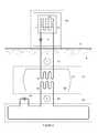
- FIG. 1is a schematic representation of the most basic form of the invention as a geo-cooled solar photovoltaic power conversion apparatus.
- FIG. 2shows a geo-cooled solar photovoltaic power conversion apparatus with two closed liquid cooling loops and a liquid coolant reservoir.
- FIG. 3shows a geo-cooled solar photovoltaic power conversion apparatus with three closed liquid cooling loops, a liquid coolant reservoir and a supplemental closed forced-convection cooling subsystem within the power converter enclosure.
- FIG. 4shows a geo-cooled solar photovoltaic power conversion apparatus with three cooling liquid cooling loops, a liquid coolant reservoir where coolants in the three loops and the reservoir mix freely and a supplemental closed forced-convection cooling subsystem within the power converter enclosure.
- FIG. 5shows a geo-cooled solar photovoltaic power conversion apparatus with three closed liquid cooling loops, a liquid coolant reservoir and a supplemental open forced-convection cooling subsystem within the power converter enclosure.
- FIG. 1illustrates the most basic form of the invention as a geo-cooled solar photovoltaic power conversion apparatus comprising; power converter 50 , sub-grade heat exchanger 20 and coolant loop 1 .
- Power converter 50comprises; enclosure 51 , power converter heat producing components including but not limited to semiconductor devices, inductors, transformers, power capacitors and power supplies, referenced collectively as heat producing components 53 , power converter heat exchanger 11 and coolant pump 14 .
- Sub-grade heat exchanger 20is essentially a network of manifolds and pipes, tubing or other conduits buried in earth 6 and thermally coupled to earth 6 .
- Coolant loop 1provides a path for coolant 23 through power converter heat exchanger 11 and sub-grade heat exchanger 20 .
- Coolant pump 14circulates liquid coolant 23 through coolant loop 1 . Heat transfer from power converter heat producing components 53 to earth 6 is accomplished by transferring heat from heat producing components 53 to power converter heat exchanger 11 , to liquid coolant 23 , to sub-grade heat exchanger 20 , to earth 6 . All area below earth grade line 0 is sub-grade.
- power converter heat exchanger 11is shown schematically as a chill plate but could also be configured as a liquid-to-air heat exchanger or radiator with or without a fan wherein thermal coupling from heat producing components 53 to power converter heat exchanger 11 is accomplished with convection rather than conduction.
- FIG. 2shows a geo-cooled solar photovoltaic power conversion apparatus with two cooling loops, shown schematically as coolant loop 1 and coolant loop 2 .
- Photovoltaic power converter 50comprises; enclosure 51 , heat producing components including but not limited to; semiconductor devices, inductors, transformers, power capacitors and power supplies, referenced collectively as heat producing components 53 , power converter heat exchanger 11 and coolant pump 14 .
- Coolant reservoir 40comprises; tank 41 filled with liquid coolant 43 , reservoir heat exchanger 12 and reservoir heat exchanger 22 .
- Sub-grade heat exchanger 20comprises a network of manifolds, pipes, tubing or other conduits buried in earth 6 and thermally coupled to earth 6 .
- Coolant loop 1provides a path for coolant 13 through power converter heat exchanger 11 and reservoir heat exchanger 12 .
- Coolant loop 2provides a path for coolant 23 through reservoir heat exchanger 22 and sub-grade heat exchanger 20 .
- Coolant pump 14circulates liquid coolant 13 through coolant loop 1 and coolant pump 24 circulates liquid coolant 23 through coolant loop 2 .
- Heat transfer from power converter heat producing components 53 to earth 6is accomplished by transferring heat from heat producing components 53 to power converter heat exchanger 11 , to liquid coolant 13 , to reservoir heat exchanger 12 , through liquid coolant 43 , to coolant reservoir heat exchanger 22 , to liquid coolant 23 , to sub-grade heat exchanger 20 , to earth 6 .
- Coolant reservoir 40provides bulk thermal storage for the cooling system.
- coolant loops 1 and 2are closed systems wherein liquid coolants 13 and 23 do not mix, and do not mix with liquid coolant 43 .
- reservoir heat exchangers 12 and 22may be eliminated and coolants 13 , 23 and 43 would mix in/as a single closed system.
- FIG. 3shows a geo-cooled solar photovoltaic power conversion apparatus with three cooling loops, shown schematically as coolant loops 1 , 2 and 3 and is the preferred embodiment of the invention.
- Photovoltaic power converter 50comprises; enclosure 51 , enclosure thermal insulation 52 , primary heat producing components including but not limited to; semiconductor devices, inductors, transformers and power capacitors, referenced collectively as primary heat producing components 53 , secondary heat producing components including but not limited to; inductors, transformers, power capacitors and power supplies, referenced collectively secondary heat producing components 54 , power converter chill plate heat exchanger 11 , power converter air-to-liquid heat exchanger 31 , cooling fan 35 , air plenum 55 , coolant pump 14 and coolant pump 34 .
- Coolant reservoir 40comprises; tank 41 filled with liquid coolant 43 , and reservoir heat exchangers 12 , 22 and 32 .
- Sub-grade heat exchanger 20comprises a network of manifolds, pipes, tubing or other conduits buried in earth 6 and thermally coupled to earth 6 .
- Power converter 50essentially sits at earth grade 0 and all area below earth grade line 0 is sub-grade.
- Coolant loop 1provides a path for liquid coolant 13 through power converter heat exchanger 11 and reservoir heat exchanger 12 .
- Coolant loop 2provides a path for liquid coolant 23 through reservoir heat exchanger 22 and sub-grade heat exchanger 20 .
- Coolant loop 3provides a path for liquid coolant 33 through power converter air-to-liquid heat exchanger 31 and reservoir heat exchanger 32 .
- Coolant pump 14circulates liquid coolant 13 through coolant loop 1
- coolant pump 24circulates liquid coolant 23 through coolant loop 2
- coolant pump 34circulates liquid coolant 33 through coolant loop 3 .
- Heat transfer from primary power converter heat producing components 53 to earth 6is accomplished by transferring heat from primary heat producing components 53 to power converter heat exchanger 11 , to liquid coolant 13 , to reservoir heat exchanger 12 , through liquid coolant 43 , to coolant reservoir heat exchanger 22 , to liquid coolant 23 , to sub-grade heat exchanger 20 , to earth 6 .
- Heat transfer from secondary power converter heat producing components 54 to earth 6is accomplished by transferring heat from secondary heat producing components 54 through air within power converter enclosure 51 circulated by fan 35 and directed as shown by arrows 7 by air plenum 55 , to power converter air-to-liquid heat exchanger 31 , to liquid coolant 33 , to reservoir heat exchanger 32 , through liquid coolant 43 , to coolant reservoir heat exchanger 22 , to liquid coolant 23 , to sub-grade heat exchanger 20 , to earth 6 .
- Coolant reservoir 40provides bulk thermal storage for the cooling system. As shown in FIG. 3 , coolant loops 1 2 and 3 are closed systems wherein liquid coolants 13 , 23 and 33 do not mix, and do not mix with liquid coolant 43 .
- FIG. 4is identical to FIG. 3 except that heat exchangers 12 , 22 and 32 are removed from coolant reservoir 40 such that liquid coolants 13 , 23 , 33 and 43 are common and form one closed coolant system.
- impeller 49is added to coolant reservoir 40 to circulate liquid coolant 43 within tank 41 .
- FIG. 5is essentially identical to FIG. 3 except that ambient air 8 external to enclosure 51 is pushed through power converter air-to-liquid heat exchanger 31 by fan 35 and is directed over power converter secondary heat producing components 54 and then forced out of an exhaust port as shown by arrow 9 .
- external ambient air 8is pre-cooled by power converter air-to-liquid heat exchanger 31 before being used to convection-cool power converter secondary heat producing components 52 .
- power converter air-to-liquid heat exchanger 31 by fan 35 positionsmay be transposed so that air 8 is pulled through power converter air-to-liquid heat exchanger 31 by fan 35 .
- geo-cooling systems disclosed hereinmay also be used as geo-heating systems to heat power converter 50 to prevent condensation or frost within power converter enclosure 51 during the night or during periods of low or no photovoltaic power production.
- the sub-grade heat exchangers ( 20 ) disclosed hereinmay share trenches with sub-grade photovoltaic system wiring conduits.
- the sub-grade heat exchangers ( 20 ) disclosed hereinmay comprise metallic pipe, metallic tubing or other metallic conduits that may be bonded to the photovoltaic system ground grid to function as or to augment the photovoltaic system ground grid.
- coolant pump 24is shown for clarity in a sub-grade location. In practice coolant pump 24 may be located above-grade to facilitate ease of maintenance and replacement.
- liquid coolant reservoir 40is shown in a sub-grade location but may also be located above-grade to facilitate ease of maintenance and replacement.
- the geo-cooled solar photovoltaic power conversion apparatuses disclose hereinwill comprise a means to control the speed of said liquid coolant pumps ( 14 , 24 , 34 ) as some function of at least one of the temperature of any said coolant, ambient air temperature, photovoltaic power converter temperature, the temperature of at least one heat producing component, the temperature of the earth or the power converter output power.
- the liquid coolant reservoir disclosed herein ( 40 )may provide enough thermal capacity to essentially absorb enough heat from all the power converter heat producing components to operate the heat producing components within their thermal capabilities during daylight hours to either reduce the heat removal demand of the sub-grade heat exchanger or eliminate it completely.
- the inventionis a novel way of cooling photovoltaic power converters which utilizes the large land area required for solar power plants and/or bulk liquid storage as heat sinks or a heat sink, respectively, for photovoltaic power converter waste heat.
- prior-art, anti-condensation heaters interior to the power converter enclosureare eliminated by geo-heating the power converter at night.
Landscapes
- Engineering & Computer Science (AREA)
- Mechanical Engineering (AREA)
- General Engineering & Computer Science (AREA)
- Life Sciences & Earth Sciences (AREA)
- Sustainable Development (AREA)
- Sustainable Energy (AREA)
- Chemical & Material Sciences (AREA)
- Combustion & Propulsion (AREA)
- Physics & Mathematics (AREA)
- Thermal Sciences (AREA)
- Cooling Or The Like Of Electrical Apparatus (AREA)
- Photovoltaic Devices (AREA)
Abstract
Description
Claims (12)
Priority Applications (1)
| Application Number | Priority Date | Filing Date | Title |
|---|---|---|---|
| US13/570,218US8648249B1 (en) | 2012-08-08 | 2012-08-08 | Geo-cooled photovoltaic power converter |
Applications Claiming Priority (1)
| Application Number | Priority Date | Filing Date | Title |
|---|---|---|---|
| US13/570,218US8648249B1 (en) | 2012-08-08 | 2012-08-08 | Geo-cooled photovoltaic power converter |
Publications (2)
| Publication Number | Publication Date |
|---|---|
| US8648249B1true US8648249B1 (en) | 2014-02-11 |
| US20140041709A1 US20140041709A1 (en) | 2014-02-13 |
Family
ID=50032743
Family Applications (1)
| Application Number | Title | Priority Date | Filing Date |
|---|---|---|---|
| US13/570,218Expired - Fee RelatedUS8648249B1 (en) | 2012-08-08 | 2012-08-08 | Geo-cooled photovoltaic power converter |
Country Status (1)
| Country | Link |
|---|---|
| US (1) | US8648249B1 (en) |
Cited By (9)
| Publication number | Priority date | Publication date | Assignee | Title |
|---|---|---|---|---|
| US20120211195A1 (en)* | 2011-02-18 | 2012-08-23 | Heise Lorne R | Control for Geothermal Heating System |
| CN103795327A (en)* | 2014-02-25 | 2014-05-14 | 江苏万宇电能科技有限公司 | Small photo-thermal combination solar power station |
| US20160089970A1 (en)* | 2014-09-30 | 2016-03-31 | Ford Global Technologies, Llc | Cooling system for a vehicle solar panel |
| US9649948B2 (en) | 2014-08-25 | 2017-05-16 | Ford Global Technologies, Llc | Self-locating multi-coil system for wireless vehicle charging |
| US10050584B2 (en) | 2016-03-16 | 2018-08-14 | Hardware Labs Performance Systems, Inc. | Cooling apparatus for solar panels |
| US10050165B2 (en)* | 2016-04-12 | 2018-08-14 | International Business Machines Corporation | Photovoltaic system with non-uniformly cooled photovoltaic cells |
| WO2019024061A1 (en)* | 2017-08-03 | 2019-02-07 | 大连理工大学 | Pvt heat pump system capable of realizing divided daytime and night-time heat, power and cooling supply by means of solar radiation and sky cold radiation |
| US10349560B2 (en)* | 2017-10-19 | 2019-07-09 | Hewlett Packard Enterprise Development Lp | Cooling module |
| DK181910B1 (en)* | 2024-02-09 | 2025-03-18 | Kk Wind Solutions As | Focused temperature regulation unit |
Families Citing this family (2)
| Publication number | Priority date | Publication date | Assignee | Title |
|---|---|---|---|---|
| US10225961B2 (en) | 2014-11-18 | 2019-03-05 | Ge Global Sourcing Llc | System and method for cooling power electronics |
| CA2991700C (en)* | 2015-08-31 | 2020-10-27 | Halliburton Energy Services, Inc. | Monitoring system for cold climate |
Citations (44)
| Publication number | Priority date | Publication date | Assignee | Title |
|---|---|---|---|---|
| US3924954A (en)* | 1973-04-20 | 1975-12-09 | Commissariat Energie Atomique | Heliograph |
| US3986021A (en)* | 1975-10-24 | 1976-10-12 | The United States Of America As Represented By The Secretary Of The Navy | Passive solar tracking system for steerable Fresnel elements |
| US3991741A (en)* | 1975-03-20 | 1976-11-16 | Northrup Jr Leonard L | Roof-lens solar collector |
| US4021323A (en)* | 1975-07-28 | 1977-05-03 | Texas Instruments Incorporated | Solar energy conversion |
| US4075034A (en)* | 1977-02-08 | 1978-02-21 | Butler David M | Solar converter |
| US4172740A (en)* | 1975-12-24 | 1979-10-30 | Campbell William P Iii | Solar energy system |
| US4202715A (en)* | 1976-06-02 | 1980-05-13 | Georg Ziemba | Method for making a spherical mirror |
| US4217147A (en)* | 1976-06-02 | 1980-08-12 | Georg Ziemba | Facility for generating technically useable energy by conversion of solar energy |
| US4830677A (en)* | 1988-04-22 | 1989-05-16 | Geisler Jr Herbert A | Solar generator |
| US4841946A (en)* | 1984-02-17 | 1989-06-27 | Marks Alvin M | Solar collector, transmitter and heater |
| US5269851A (en)* | 1991-02-25 | 1993-12-14 | United Solar Technologies, Inc. | Solar energy system |
| US5394075A (en)* | 1992-12-04 | 1995-02-28 | Hughes Aircraft Company | Spacecraft bus regulation using solar panel position |
| US5445177A (en)* | 1990-04-30 | 1995-08-29 | Laing; Johanes L. N. | Platform for the utilization of solar power |
| US5575860A (en)* | 1994-08-11 | 1996-11-19 | Cherney; Matthew | Fiber optic power-generation system |
| US5932885A (en)* | 1997-05-19 | 1999-08-03 | Mcdermott Technology, Inc. | Thermophotovoltaic electric generator |
| US6372978B1 (en)* | 2000-12-21 | 2002-04-16 | Carmine Cifaldi | Wind/sun solar collection system (HS2) |
| US20020060556A1 (en)* | 2000-10-12 | 2002-05-23 | Capstone Turbine Corporation | Detection of islanded behavior and anti-islanding protection of a generation in grid-connected mode |
| US6463672B1 (en)* | 2000-07-03 | 2002-10-15 | The United States Of America As Represented By The Secretary Of The Air Force | Mitigation of spacecraft charging by means of ionized water vapor |
| US6489553B1 (en)* | 2001-05-30 | 2002-12-03 | Jx Crystals Inc. | TPV cylindrical generator for home cogeneration |
| US6498290B1 (en)* | 2001-05-29 | 2002-12-24 | The Sun Trust, L.L.C. | Conversion of solar energy |
| US6857269B2 (en)* | 2003-05-08 | 2005-02-22 | The Aerospace Corporation | Capillary two-phase thermodynamic power conversion cycle system |
| US6918254B2 (en)* | 2003-10-01 | 2005-07-19 | The Aerospace Corporation | Superheater capillary two-phase thermodynamic power conversion cycle system |
| US7076965B2 (en)* | 2001-03-28 | 2006-07-18 | John Beavis Lasich | Cooling circuit for receiver of solar radiation |
| US7100369B2 (en)* | 2003-05-06 | 2006-09-05 | Denso Corporation | Thermoelectric generating device |
| US7253353B2 (en)* | 2004-06-30 | 2007-08-07 | General Motors Corporation | Thermoelectric augmented hybrid electric propulsion system |
| US20080078435A1 (en)* | 2003-08-22 | 2008-04-03 | Johnson D Alan E | Mechanical/Thermo-Voltaic Solar Power System |
| US20080092541A1 (en)* | 2006-09-06 | 2008-04-24 | Harris Corporation | System for providing continuous electric power from solar energy |
| US20080131830A1 (en)* | 2006-12-05 | 2008-06-05 | Nix Martin E | Use of renewable energy like solar, wind, geothermal, biomass, and hydropower for manufacturing combustion air for a fossil fuel burner and firebox |
| US20080217998A1 (en)* | 2005-02-26 | 2008-09-11 | Parmley Daniel W | Renewable energy power systems |
| US7451612B2 (en)* | 2005-09-14 | 2008-11-18 | Free Energy Solutions Inc. | Geothermal exchange system incorporating a thermally superconducting medium |
| US20090120091A1 (en)* | 2007-11-08 | 2009-05-14 | Dubois John R | Power generation system |
| US20090120090A1 (en)* | 2007-11-08 | 2009-05-14 | Dubois John R | Geothermal power generation system and method for adapting to mine shafts |
| US20090315330A1 (en)* | 2008-06-20 | 2009-12-24 | Dederick Robert J | Facility for refueling of clean air vehicles/marine craft and generation and storage of power |
| US20100133903A1 (en)* | 2007-05-09 | 2010-06-03 | Alfred Rufer | Energy Storage Systems |
| US20100154855A1 (en)* | 2008-12-18 | 2010-06-24 | David Nemir | Thin walled thermoelectric devices and methods for production thereof |
| US7767903B2 (en)* | 2003-11-10 | 2010-08-03 | Marshall Robert A | System and method for thermal to electric conversion |
| US20110001436A1 (en)* | 2008-04-14 | 2011-01-06 | Digital Lumens, Inc. | Power Management Unit with Light Module Identification |
| US20110001438A1 (en)* | 2008-04-14 | 2011-01-06 | Digital Lumens, Inc. | Power Management Unit with Temperature Protection |
| US8104465B2 (en)* | 2003-05-12 | 2012-01-31 | Ramot At Tel-Aviv University Ltd. | Small-scale, concentrating, solar CHP system |
| US8165435B2 (en)* | 2009-03-16 | 2012-04-24 | Fernando Ramon Martin-Lopez | Solar energy collector |
| US8180505B2 (en)* | 2007-11-07 | 2012-05-15 | The Aerospace Corporation | Spacecraft solar cell monitoring system |
| US8207821B2 (en)* | 2003-05-05 | 2012-06-26 | Philips Solid-State Lighting Solutions, Inc. | Lighting methods and systems |
| US8378621B2 (en)* | 2010-02-08 | 2013-02-19 | Tara Chand Singhal | Integrated systems for harnessing solar and wind energy |
| US8448876B2 (en)* | 2009-06-12 | 2013-05-28 | Tai-Her Yang | Semiconductor application installation adapted with a temperature equalization system |
- 2012
- 2012-08-08USUS13/570,218patent/US8648249B1/ennot_activeExpired - Fee Related
Patent Citations (45)
| Publication number | Priority date | Publication date | Assignee | Title |
|---|---|---|---|---|
| US3924954A (en)* | 1973-04-20 | 1975-12-09 | Commissariat Energie Atomique | Heliograph |
| US3991741A (en)* | 1975-03-20 | 1976-11-16 | Northrup Jr Leonard L | Roof-lens solar collector |
| US4021323A (en)* | 1975-07-28 | 1977-05-03 | Texas Instruments Incorporated | Solar energy conversion |
| US3986021A (en)* | 1975-10-24 | 1976-10-12 | The United States Of America As Represented By The Secretary Of The Navy | Passive solar tracking system for steerable Fresnel elements |
| US4172740A (en)* | 1975-12-24 | 1979-10-30 | Campbell William P Iii | Solar energy system |
| US4202715A (en)* | 1976-06-02 | 1980-05-13 | Georg Ziemba | Method for making a spherical mirror |
| US4217147A (en)* | 1976-06-02 | 1980-08-12 | Georg Ziemba | Facility for generating technically useable energy by conversion of solar energy |
| US4075034A (en)* | 1977-02-08 | 1978-02-21 | Butler David M | Solar converter |
| US4841946A (en)* | 1984-02-17 | 1989-06-27 | Marks Alvin M | Solar collector, transmitter and heater |
| US4830677A (en)* | 1988-04-22 | 1989-05-16 | Geisler Jr Herbert A | Solar generator |
| US5445177A (en)* | 1990-04-30 | 1995-08-29 | Laing; Johanes L. N. | Platform for the utilization of solar power |
| US5269851A (en)* | 1991-02-25 | 1993-12-14 | United Solar Technologies, Inc. | Solar energy system |
| US5394075A (en)* | 1992-12-04 | 1995-02-28 | Hughes Aircraft Company | Spacecraft bus regulation using solar panel position |
| US5575860A (en)* | 1994-08-11 | 1996-11-19 | Cherney; Matthew | Fiber optic power-generation system |
| US5932885A (en)* | 1997-05-19 | 1999-08-03 | Mcdermott Technology, Inc. | Thermophotovoltaic electric generator |
| US6463672B1 (en)* | 2000-07-03 | 2002-10-15 | The United States Of America As Represented By The Secretary Of The Air Force | Mitigation of spacecraft charging by means of ionized water vapor |
| US20040178641A1 (en)* | 2000-10-12 | 2004-09-16 | Capstone Turbine Corporation | Detection of islanded behavior and anti-islanding protection of a generator in grid-connected mode |
| US20020060556A1 (en)* | 2000-10-12 | 2002-05-23 | Capstone Turbine Corporation | Detection of islanded behavior and anti-islanding protection of a generation in grid-connected mode |
| US6372978B1 (en)* | 2000-12-21 | 2002-04-16 | Carmine Cifaldi | Wind/sun solar collection system (HS2) |
| US7076965B2 (en)* | 2001-03-28 | 2006-07-18 | John Beavis Lasich | Cooling circuit for receiver of solar radiation |
| US6498290B1 (en)* | 2001-05-29 | 2002-12-24 | The Sun Trust, L.L.C. | Conversion of solar energy |
| US6489553B1 (en)* | 2001-05-30 | 2002-12-03 | Jx Crystals Inc. | TPV cylindrical generator for home cogeneration |
| US8207821B2 (en)* | 2003-05-05 | 2012-06-26 | Philips Solid-State Lighting Solutions, Inc. | Lighting methods and systems |
| US7100369B2 (en)* | 2003-05-06 | 2006-09-05 | Denso Corporation | Thermoelectric generating device |
| US6857269B2 (en)* | 2003-05-08 | 2005-02-22 | The Aerospace Corporation | Capillary two-phase thermodynamic power conversion cycle system |
| US8104465B2 (en)* | 2003-05-12 | 2012-01-31 | Ramot At Tel-Aviv University Ltd. | Small-scale, concentrating, solar CHP system |
| US20080078435A1 (en)* | 2003-08-22 | 2008-04-03 | Johnson D Alan E | Mechanical/Thermo-Voltaic Solar Power System |
| US6918254B2 (en)* | 2003-10-01 | 2005-07-19 | The Aerospace Corporation | Superheater capillary two-phase thermodynamic power conversion cycle system |
| US7767903B2 (en)* | 2003-11-10 | 2010-08-03 | Marshall Robert A | System and method for thermal to electric conversion |
| US7253353B2 (en)* | 2004-06-30 | 2007-08-07 | General Motors Corporation | Thermoelectric augmented hybrid electric propulsion system |
| US20080217998A1 (en)* | 2005-02-26 | 2008-09-11 | Parmley Daniel W | Renewable energy power systems |
| US7451612B2 (en)* | 2005-09-14 | 2008-11-18 | Free Energy Solutions Inc. | Geothermal exchange system incorporating a thermally superconducting medium |
| US20080092541A1 (en)* | 2006-09-06 | 2008-04-24 | Harris Corporation | System for providing continuous electric power from solar energy |
| US20080131830A1 (en)* | 2006-12-05 | 2008-06-05 | Nix Martin E | Use of renewable energy like solar, wind, geothermal, biomass, and hydropower for manufacturing combustion air for a fossil fuel burner and firebox |
| US20100133903A1 (en)* | 2007-05-09 | 2010-06-03 | Alfred Rufer | Energy Storage Systems |
| US8180505B2 (en)* | 2007-11-07 | 2012-05-15 | The Aerospace Corporation | Spacecraft solar cell monitoring system |
| US20090120090A1 (en)* | 2007-11-08 | 2009-05-14 | Dubois John R | Geothermal power generation system and method for adapting to mine shafts |
| US20090120091A1 (en)* | 2007-11-08 | 2009-05-14 | Dubois John R | Power generation system |
| US20110001436A1 (en)* | 2008-04-14 | 2011-01-06 | Digital Lumens, Inc. | Power Management Unit with Light Module Identification |
| US20110001438A1 (en)* | 2008-04-14 | 2011-01-06 | Digital Lumens, Inc. | Power Management Unit with Temperature Protection |
| US20090315330A1 (en)* | 2008-06-20 | 2009-12-24 | Dederick Robert J | Facility for refueling of clean air vehicles/marine craft and generation and storage of power |
| US20100154855A1 (en)* | 2008-12-18 | 2010-06-24 | David Nemir | Thin walled thermoelectric devices and methods for production thereof |
| US8165435B2 (en)* | 2009-03-16 | 2012-04-24 | Fernando Ramon Martin-Lopez | Solar energy collector |
| US8448876B2 (en)* | 2009-06-12 | 2013-05-28 | Tai-Her Yang | Semiconductor application installation adapted with a temperature equalization system |
| US8378621B2 (en)* | 2010-02-08 | 2013-02-19 | Tara Chand Singhal | Integrated systems for harnessing solar and wind energy |
Cited By (14)
| Publication number | Priority date | Publication date | Assignee | Title |
|---|---|---|---|---|
| US20120211195A1 (en)* | 2011-02-18 | 2012-08-23 | Heise Lorne R | Control for Geothermal Heating System |
| CN103795327A (en)* | 2014-02-25 | 2014-05-14 | 江苏万宇电能科技有限公司 | Small photo-thermal combination solar power station |
| CN103795327B (en)* | 2014-02-25 | 2015-12-16 | 江苏万丰光伏有限公司 | A kind of small-sized photo-thermal coupling solar power station |
| US9649948B2 (en) | 2014-08-25 | 2017-05-16 | Ford Global Technologies, Llc | Self-locating multi-coil system for wireless vehicle charging |
| US20160089970A1 (en)* | 2014-09-30 | 2016-03-31 | Ford Global Technologies, Llc | Cooling system for a vehicle solar panel |
| US9481241B2 (en)* | 2014-09-30 | 2016-11-01 | Ford Global Technologies, Llc | Cooling system for a vehicle solar panel |
| US10050584B2 (en) | 2016-03-16 | 2018-08-14 | Hardware Labs Performance Systems, Inc. | Cooling apparatus for solar panels |
| US10050165B2 (en)* | 2016-04-12 | 2018-08-14 | International Business Machines Corporation | Photovoltaic system with non-uniformly cooled photovoltaic cells |
| US11094840B2 (en) | 2016-04-12 | 2021-08-17 | International Business Machines Corporation | Photovoltaic system with non-uniformly cooled photovoltaic cells |
| WO2019024061A1 (en)* | 2017-08-03 | 2019-02-07 | 大连理工大学 | Pvt heat pump system capable of realizing divided daytime and night-time heat, power and cooling supply by means of solar radiation and sky cold radiation |
| US11060742B2 (en) | 2017-08-03 | 2021-07-13 | Dalian University Of Technology | PVT heat pump system capable of achieving day-night time-shared combined cooling, heating and power using solar radiation and sky cold radiation |
| US10349560B2 (en)* | 2017-10-19 | 2019-07-09 | Hewlett Packard Enterprise Development Lp | Cooling module |
| DK181910B1 (en)* | 2024-02-09 | 2025-03-18 | Kk Wind Solutions As | Focused temperature regulation unit |
| DK202470036A1 (en)* | 2024-02-09 | 2025-03-18 | Kk Wind Solutions As | Focused temperature regulation unit |
Also Published As
| Publication number | Publication date |
|---|---|
| US20140041709A1 (en) | 2014-02-13 |
Similar Documents
| Publication | Publication Date | Title |
|---|---|---|
| US8648249B1 (en) | Geo-cooled photovoltaic power converter | |
| AU2017213536B2 (en) | Liquid submerged, horizontal computer server rack and systems and methods of cooling such a server rack | |
| US9185830B2 (en) | Thermoelectric-enhanced, liquid-based cooling of a multi-component electronic system | |
| US9351431B2 (en) | Cooling system with automated seasonal freeze protection | |
| US9363924B2 (en) | Ground-based heat sink facilitating electronic system cooling | |
| US10653041B2 (en) | Fluid-cooled data centres without air conditioning, and methods for operating same | |
| US8747060B2 (en) | Cooling and climate control system and method for a wind turbine | |
| CN103185411A (en) | Integrated environmental control systems and methods for controlling environmental temperature of an enclosed space | |
| EP3107363B1 (en) | Renewable energy based datacenter cooling | |
| US20180376624A1 (en) | Thermal containment system with integrated cooling unit for waterborne or land-based data centers | |
| US20110198060A1 (en) | Heat Dissipation Apparatus for Data Center | |
| CN105493271B (en) | Cooling device for current converter module | |
| CN111641139A (en) | Cold-storage type water-cooling box-type substation | |
| US11805627B2 (en) | Data center heat recovery system | |
| CN105474385A (en) | Cooling device for a current converter module | |
| CN107728752A (en) | Enclosure heat radiation system for high-performance computer |
Legal Events
| Date | Code | Title | Description |
|---|---|---|---|
| STCF | Information on status: patent grant | Free format text:PATENTED CASE | |
| FEPP | Fee payment procedure | Free format text:PAT HOLDER NO LONGER CLAIMS SMALL ENTITY STATUS, ENTITY STATUS SET TO UNDISCOUNTED (ORIGINAL EVENT CODE: STOL); ENTITY STATUS OF PATENT OWNER: LARGE ENTITY | |
| AS | Assignment | Owner name:RENEWABLE POWER CONVERSION, INC., CALIFORNIA Free format text:ASSIGNMENT OF ASSIGNORS INTEREST;ASSIGNOR:WEST, RICHARD TRAVIS;REEL/FRAME:041585/0805 Effective date:20170314 | |
| FPAY | Fee payment | Year of fee payment:4 | |
| AS | Assignment | Owner name:PARKER-HANNIFIN CORPORATION, OHIO Free format text:ASSIGNMENT OF ASSIGNORS INTEREST;ASSIGNOR:RENEWABLE POWER CONVERSION, INC.;REEL/FRAME:042764/0207 Effective date:20170418 | |
| FEPP | Fee payment procedure | Free format text:PETITION RELATED TO MAINTENANCE FEES GRANTED (ORIGINAL EVENT CODE: PTGR) | |
| MAFP | Maintenance fee payment | Free format text:PAYMENT OF MAINTENANCE FEE UNDER 1.28(C) (ORIGINAL EVENT CODE: M1559) | |
| AS | Assignment | Owner name:PARKER INTANGIBLES, LLC, OHIO Free format text:ASSIGNMENT OF ASSIGNORS INTEREST;ASSIGNOR:PARKER-HANNIFIN CORPORATION;REEL/FRAME:045843/0859 Effective date:20180405 | |
| FEPP | Fee payment procedure | Free format text:MAINTENANCE FEE REMINDER MAILED (ORIGINAL EVENT CODE: REM.); ENTITY STATUS OF PATENT OWNER: LARGE ENTITY | |
| LAPS | Lapse for failure to pay maintenance fees | Free format text:PATENT EXPIRED FOR FAILURE TO PAY MAINTENANCE FEES (ORIGINAL EVENT CODE: EXP.); ENTITY STATUS OF PATENT OWNER: LARGE ENTITY | |
| STCH | Information on status: patent discontinuation | Free format text:PATENT EXPIRED DUE TO NONPAYMENT OF MAINTENANCE FEES UNDER 37 CFR 1.362 | |
| FP | Lapsed due to failure to pay maintenance fee | Effective date:20220211 |