US8647369B2 - Minimal profile anterior bracket for spinal fixation - Google Patents
Minimal profile anterior bracket for spinal fixationDownload PDFInfo
- Publication number
- US8647369B2 US8647369B2US13/111,198US201113111198AUS8647369B2US 8647369 B2US8647369 B2US 8647369B2US 201113111198 AUS201113111198 AUS 201113111198AUS 8647369 B2US8647369 B2US 8647369B2
- Authority
- US
- United States
- Prior art keywords
- pair
- wedge
- spinal fixation
- members
- fixation device
- Prior art date
- Legal status (The legal status is an assumption and is not a legal conclusion. Google has not performed a legal analysis and makes no representation as to the accuracy of the status listed.)
- Expired - Fee Related, expires
Links
- 210000000988bone and boneAnatomy0.000claimsabstractdescription39
- 239000000463materialSubstances0.000claimsdescription16
- 230000006835compressionEffects0.000claimsdescription3
- 238000007906compressionMethods0.000claimsdescription3
- 239000007943implantSubstances0.000description25
- 238000000034methodMethods0.000description10
- 230000006641stabilisationEffects0.000description3
- 238000011105stabilizationMethods0.000description3
- 239000004696Poly ether ether ketoneSubstances0.000description2
- 229910001069Ti alloyInorganic materials0.000description2
- RTAQQCXQSZGOHL-UHFFFAOYSA-NTitaniumChemical compound[Ti]RTAQQCXQSZGOHL-UHFFFAOYSA-N0.000description2
- 230000008901benefitEffects0.000description2
- JUPQTSLXMOCDHR-UHFFFAOYSA-Nbenzene-1,4-diol;bis(4-fluorophenyl)methanoneChemical compoundOC1=CC=C(O)C=C1.C1=CC(F)=CC=C1C(=O)C1=CC=C(F)C=C1JUPQTSLXMOCDHR-UHFFFAOYSA-N0.000description2
- 208000037265diseases, disorders, signs and symptomsDiseases0.000description2
- 230000004927fusionEffects0.000description2
- 238000012986modificationMethods0.000description2
- 230000004048modificationEffects0.000description2
- 229920002530polyetherether ketonePolymers0.000description2
- 210000004872soft tissueAnatomy0.000description2
- 125000006850spacer groupChemical group0.000description2
- 238000003786synthesis reactionMethods0.000description2
- 239000010936titaniumSubstances0.000description2
- 229910052719titaniumInorganic materials0.000description2
- 210000005166vasculatureAnatomy0.000description2
- 229910000684Cobalt-chromeInorganic materials0.000description1
- 206010061246Intervertebral disc degenerationDiseases0.000description1
- 206010023509KyphosisDiseases0.000description1
- 208000007623LordosisDiseases0.000description1
- 206010028980NeoplasmDiseases0.000description1
- 208000020307Spinal diseaseDiseases0.000description1
- 208000020339Spinal injuryDiseases0.000description1
- 208000007103SpondylolisthesisDiseases0.000description1
- 208000027418Wounds and injuryDiseases0.000description1
- 229910045601alloyInorganic materials0.000description1
- 239000000956alloySubstances0.000description1
- 239000010952cobalt-chromeSubstances0.000description1
- 210000002808connective tissueAnatomy0.000description1
- 238000010276constructionMethods0.000description1
- 230000008878couplingEffects0.000description1
- 238000010168coupling processMethods0.000description1
- 238000005859coupling reactionMethods0.000description1
- 230000006378damageEffects0.000description1
- 208000018180degenerative disc diseaseDiseases0.000description1
- 230000003292diminished effectEffects0.000description1
- 201000010099diseaseDiseases0.000description1
- 208000035475disorderDiseases0.000description1
- 230000002401inhibitory effectEffects0.000description1
- 208000014674injuryDiseases0.000description1
- 208000021600intervertebral disc degenerative diseaseDiseases0.000description1
- 210000004705lumbosacral regionAnatomy0.000description1
- 229910052751metalInorganic materials0.000description1
- 239000002184metalSubstances0.000description1
- 210000005036nerveAnatomy0.000description1
- 210000000653nervous systemAnatomy0.000description1
- 238000005457optimizationMethods0.000description1
- 230000008569processEffects0.000description1
- 206010039722scoliosisDiseases0.000description1
- 210000000278spinal cordAnatomy0.000description1
- 210000001032spinal nerveAnatomy0.000description1
- 239000010935stainless steelSubstances0.000description1
- 229910001220stainless steelInorganic materials0.000description1
- 210000000115thoracic cavityAnatomy0.000description1
- 210000002517zygapophyseal jointAnatomy0.000description1
Images


Classifications
- A—HUMAN NECESSITIES
- A61—MEDICAL OR VETERINARY SCIENCE; HYGIENE
- A61B—DIAGNOSIS; SURGERY; IDENTIFICATION
- A61B17/00—Surgical instruments, devices or methods
- A61B17/56—Surgical instruments or methods for treatment of bones or joints; Devices specially adapted therefor
- A61B17/58—Surgical instruments or methods for treatment of bones or joints; Devices specially adapted therefor for osteosynthesis, e.g. bone plates, screws or setting implements
- A61B17/68—Internal fixation devices, including fasteners and spinal fixators, even if a part thereof projects from the skin
- A61B17/70—Spinal positioners or stabilisers, e.g. stabilisers comprising fluid filler in an implant
- A61B17/7059—Cortical plates
Definitions
- the present disclosurerelates to spinal fixation and, more particularly, to anterior brackets for providing support and stabilization to the spinal column and for inhibiting expulsion of an interbody implant disposed within an intervertebral space.
- the human spinal columnis a complex system of bones and connective tissues that provides support for the human body and protection for the spinal cord and nerves.
- the adult spineis comprised of an upper and lower portion.
- the upper portioncontains 24 discrete bones, which are subdivided into three areas including 7 cervical vertebrae, 12 thoracic vertebrae, and 5 lumbar vertebrae.
- the lower portionis comprised of the sacral and coccygeal bones.
- the vertebrae, or vertebral bodiesprogressively increase in size from the upper portion downwards to the lower portion.
- intervertebral discalong with two posterior facet joints cushion and dampen the various translational and rotational forces exerted upon the spinal column.
- the intervertebral discsare spacers located between adjacent vertebral bodies, while the facets provide stability at the posterior portions of adjacent vertebrae.
- the spineis a flexible structure capable of a large range of motion.
- disorders, diseases and types of injurywhich restrict the range of motion of the spine or interfere with important elements of the nervous system.
- Theseinclude, but are not limited to, scoliosis, kyphosis, excessive lordosis, spondylolisthesis, slipped or ruptured discs, degenerative disc disease, vertebral body fracture, and tumors.
- Persons suffering from any of the above conditionsmay experience extreme or debilitating pain and oftentimes experience diminished nerve function.
- Spinal fixation apparatusesare widely employed in surgical processes for correcting spinal injuries and diseases.
- interbody implantsthat are utilized to take the place of the disc
- PEEK interbody spacersPEEK interbody spacers
- metal cagesmetal cages
- cadaver and human bone implantsPEEK interbody spacers
- additional implantsare commonly employed.
- longitudinally linked rodsmay be secured to coupling elements which, in turn, are secured to bone by spinal bone fixation fasteners, e.g., pedicle screws, hooks, etc.
- plate and screw systemsmay be employed to stabilize and secure the anterior or lateral portion of the spine.
- an interbody implantis placed between the vertebrae and a substantially flat plate is positioned across the intervertebral space and secured to the face of each adjacent vertebral body to inhibit expulsion of the interbody implant.
- This approachmaximizes the fusion graft material that can be placed between the vertebrae, and maximizes the surface area contact between the interbody implant and the adjacent vertebra.
- a system for securing a spinal fixation device to a spineincludes one or more bone screws and a spinal fixation device.
- the one or more bone screwsmay be formed of a first material and at least a portion of the spinal fixation device may be formed of a second material.
- the first and second materialsare selected to enhance securement of the one or more bone screws to the spinal fixation device.
- the spinal fixation deviceincludes a body having a pair of longitudinal members extending between a pair of wedge members.
- the bodyis dimensioned to resist deforming forces including one or both of flexion extension forces and axial compression forces extending through the body.
- the pair of wedge membersis disposed on opposite ends of the pair of longitudinal members.
- One of the wedge membersis at least partially positionable within a first intervertebral space of the spine and the other wedge member is at least partially positionable within a second intervertebral space of the spine.
- One or both of the wedge membersis at least partially wedge shaped.
- Each wedge memberdefines one or more openings therethrough for the reception of one or more bone screws.
- One or both of the wedge membersmay define two or more openings therethrough for the passage and reception of a bone screw in each opening.
- One or more openingsare disposed at an angle relative to an anterior surface of the body in order to facilitate the securement of the bone screw to another vertebra adjacent one of the first or second intervertebral spaces.
- the pair of longitudinal membersdefines a length that spans one or more vertebra of the spine.
- the longitudinal membersare positionable within a recess defined within the one or more vertebrae.
- the pair of longitudinal membersis at least partially positionable within the one or more vertebra when the pair of wedge members is positioned within the respective first and second intervertebral spaces to maintain the body in a minimal profile orientation relative to the spine.
- the one or more longitudinal membersmay be positioned even with or substantially even with an anterior surface of the one or more vertebrae. Alternatively, the one or more longitudinal members may be recessed below an anterior surface of the one or more vertebrae.
- a method of securing a spinal fixation device to an anterior portion of a spineincludes providing a spinal fixation device having a body including one or more longitudinal members extending between a pair of wedge members. The method involves forming one or more recesses within one or more vertebrae of the spine, positioning the one or more longitudinal members at least partially within the one or more recesses, positioning one of the wedge members at least partially in a first intervertebral space of the spine, positioning the other wedge member at least partially in a second intervertebral space of the spine, and securing the spinal fixation device to the anterior portion of the spine so that the spinal fixation device is in a minimal profile orientation relative to the anterior portion of the spine.
- the methodmay include forming the one or more recesses along a plurality of contiguous vertebrae of the spine and positioning the one or more longitudinal members at least partially within the one or more recesses along each of the plurality of contiguous vertebrae.
- One part of the proceduremay include securing each wedge member to a second vertebra of the spine with one or more bone screws, the second vertebra being adjacent the one or more vertebrae.
- the methodmay involve spanning the one or more longitudinal members along a plurality of vertebrae.
- One part of the proceduremay include positioning the one or more longitudinal members within the one or more recesses in a zero profile orientation relative to the anterior portion of the spine.
- the methodmay involve positioning the one or more longitudinal members within the one or more recesses in a low profile orientation relative to the anterior portion of the spine.
- FIG. 1is a front view of a spinal fixation system shown secured to a spine in accordance with the principles of the present disclosure
- FIG. 2is a cross-sectional view of FIG. 1 taken along section line A-A;
- FIG. 3is a perspective view of a spinal fixation device in accordance with the present disclosure.
- FIG. 4is a side view of the presently disclosed spinal fixation device of FIG. 3 ;
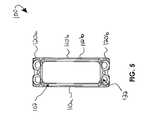
- FIG. 5is a rear view of the presently disclosed spinal fixation device of FIGS. 3 and 4 .
- proximalwill refer to the end of a device or system that is closest to the operator
- distalwill refer to the end of the device or system that is farthest from the operator.
- cephaladis used to indicate a direction toward a patient's head
- taudadindicates a direction toward the patient's feet.
- the term “medial”indicates a direction toward the middle of the body of the patient
- the term “lateral”indicates a direction toward a side of the body of the patient (i.e., away from the middle of the body of the patient).
- the term “posterior”indicates a direction toward the patient's back
- the term “anterior”indicates a direction toward the patient's front.
- Spinal fixation system 10includes a spinal fixation device 100 and a plurality of bone screws 200 for securing the spinal fixation device 100 to a spine in a minimal profile orientation relative to an anterior surface “VA” of one or more vertebrae “V.”
- the bone screws 200may be formed of a first material such as titanium alloy (e.g., Ti-6AL-4V) and at least a portion of the spinal fixation device 100 may be formed of a second material (e.g., commercially pure titanium).
- first and/or the second materialmay be formed from any suitable material including, but not limited to, commercially pure titanium, titanium alloys, cobalt chrome alloys, PEEK, stainless steel and the like materials.
- the first and second materialsare selected to enhance securement of the bone screws 200 to the spinal fixation device 100 .
- one of the first and second materialsmay be softer than the other to provide enhanced resistance to backing out of the bone screw 200 from the spinal fixation device 100 .
- U.S. Pat. No. 6,322,562 to Wolterthe entire contents of which are incorporated herein by reference.
- spinal fixation device 100may be formed as a single, monolithic piece, or may be constructed using any suitable method for joining the components thereof. As will be described in greater detail below, spinal fixation device 100 is configured for positioning at least partially within first and second intervertebral spaces “S 1 ”, “S 2 and one or more vertebral bodies of the vertebrae “V” of a patient for providing stabilization and support to the spine in a minimal profile orientation. The spinal fixation device 100 may be used to inhibit expulsion of an interbody implant “I” positioned within an intervertebral space “S” such as intervertebral spaces “S 1 ”, “S 2 ”, and/or “S 3 .”
- spinal fixation device 100includes a body 102 having an anterior surface 102 a and a posterior surface 102 b .
- the body 102includes a pair of longitudinal members including first and second longitudinal members 110 a , 110 b extending between a pair of wedge members including first and second wedge members 120 a , 120 b .
- the body 102may be dimensioned to resist deforming forces.
- first and second longitudinal members 110 a , 110 b and the first and second wedge members 120 a , 120 bmay have anterior-posterior dimensions in excess of medial-lateral dimensions, or vice versa, to optimally dispose the mass of material and efficiently resist one or both of flexion extension forces and axial compression forces extending through the body 102 .
- This optimization of dimensionsmay alter the inertia of the body 102 .
- the body 102may be dimensioned to have a low profile orientation or zero profile orientation relative to an anterior surface “VA” of the one or more vertebrae “V” when secured to a spine as will be described in greater detail below.
- first and second wedge members 120 a , 120 bare disposed on opposite ends of the first and second longitudinal members 110 a , 110 b . Illustrated in FIG. 1 , each of the first and second wedge members 120 a , 120 b are intradiscal. More specifically, the first wedge member 120 a is at least partially positionable within the first intervertebral space “S 1 ” and the second wedge member 120 b is at least partially positionable within the second intervertebral space “S 2 .” One or both of the wedge members 120 a , 120 b may be at least partially wedge shaped, as viewed in lateral profile best shown in FIG.
- wedge members 120 a , 120 bmay have any suitable shape (including any suitable geometry and/or dimension) for positioning, at least partially, within one or more of the intervertebral spaces “S.”
- each of the first and second wedge members 120 a , 120 bdefines one or more openings 122 therethrough for the reception of the one or more bone screws 200 .
- One or both of the wedge members 120 a , 120 bmay define two or more openings 122 therethrough for the passage and reception of a bone screw 200 in each opening.
- the openings 122are disposed at an angle relative to an anterior surface 102 a and/or posterior surface 102 b of the body 102 and include a lip 124 in order to facilitate the securement of a bone screw 200 to another vertebra adjacent one of the first or second intervertebral spaces “S 1 ”, “S 2 .” For example, as illustrated in FIGS.
- a first bone screw 200 asecures the first wedge member 120 a to adjacent vertebra “V 3 ” when the first wedge member 120 a is positioned in intervertebral space “S 1 .”
- a second bone screw 200 bsecures the second wedge member 120 b to adjacent vertebra “V 4 ” when the second wedge member 120 b is positioned in intervertebral space “S 2 .”
- the first and second bone screws 200 a , 200 bare positioned at an angle commensurate with the angle of the openings 122 .
- the openings 122may be positioned at any suitable angle to accommodate various dimensions and geometries of the vertebrae of various patients.
- the bone screws 200when inserted into the openings 122 , engage the spinal fixation device 100 to secure the spinal fixation device 100 to the spine.
- the first and second longitudinal members 110 a , 110 bdefine a length that intraosseously spans one or more vertebra “V” of the spine and may have any suitable dimension and/or geometry (including differing dimensions and/or geometries along the length of one or both of the first and second longitudinal members 110 a , 110 b ).
- Vvertebra
- first and second longitudinal members 110 a , 110 bare shown spanning first and second vertebrae “V 1 ”, “V 2 ” and intervertebral space “S 3 ” while the first and second wedge members 120 a , 120 b are secured in the first and second intervertebral spaces “S 1 ”, “S 2 .”
- the first and second longitudinal members 110 a , 110 bare positioned within a first recess “R 1 ” and a second recess “R 2 ” defined within the first and second vertebrae “V 1 ”, “V 2 .”
- the first and second recesses “R 1 ”, “R 2 ”may be cut longitudinally along a path having dimensions and/or geometry sufficient to accommodate one of the first and second longitudinal members 110 a , 110 b .
- first and second recess “R 1 ”, “R 2 ”may be cut into the vertebral bodies of the first and second vertebrae “V 1 ”, “V 2 ”, or any number of vertebrae “V” (including a single vertebra “V”) commensurate with the dimensions (e.g., length, width, height, etc.) and/or geometry of the first and/or second longitudinal members 110 a , 110 b , by any suitable bone cutting device such as a jig.
- first and second longitudinal members 110 a , 110 bare at least partially positionable within the respective first and second recess “R 1 ”, “R 2 ” of the one or more vertebra “V” when the first and second wedge members 120 a , 120 b are positioned within the respective first and second intervertebral spaces “S 1 ”, “S 2 ” to maintain the body 102 in a minimal profile orientation (e.g., low or zero profile orientation) relative to the spine.
- a minimal profile orientatione.g., low or zero profile orientation
- first and second wedge members 120 a , 120 bare recessed into the first and second intervertebral spaces “S 1 ”, “S 2 ” while the first and second longitudinal members 110 a , 110 b are recessed into the first and second recesses “R 1 ”, “R 2 ” to maintain the anterior surface 102 a of the body 102 in close relationship, e.g., even with or below (zero profile), or substantially even with (low profile), the anterior surface “VA” of the one or more vertebrae “V.” More specifically, a zero profile is achieved when the first and second longitudinal members 110 a , 110 b (e.g., length and/or width and/or height) are even with (e.g., flush) or below the anterior surface “VA” of the one or more vertebrae “V” along at least a portion of the one or more vertebrae “V.” In this respect, the first and second longitudinal members 110 a , 110 b may be positioned partially/entirely even with or recessed
- first and second longitudinal members 110 a , 110 be.g., length and/or width and/or height
- first and second longitudinal members 110 a , 110 bmay be partially or entirely substantially even with the anterior surface “VA” of the one or more vertebrae” to have a low profile orientation.
- the low profile orientationmay be within millimeters of the anterior surface “VA” of the one or more vertebrae “V.”
- an interbody implant “ 1 ”may be positioned between adjacent vertebrae “V 1 ” and “V 2 ” of a patient, e.g., during a spinal fusion procedure.
- one or more jigs or other known bone cutting devicesmay be used to cut the recesses “R 1 ” and “R 2 ” (low or zero profile) within one or more of the vertebrae “V”, depending on the dimensions and/or geometry of the spinal fixation device 100 and the number of vertebrae “V” and/or spinal discs and/or interbody implants which require support.
- spinal fixation device 100is inserted from the anterior side of the spine so that the posterior surface 102 b of the spinal fixation device 100 is adjacent the anterior surface “VA” of the one or more vertebrae “V” in a low or zero profile orientation.
- the spinal fixation device 100may be dimensioned to span across one or more vertebrae “V” (e.g., between two or more intervertebral disc spaces). For example as illustrated in FIGS.
- first and second wedge members 120 a , 120 bare recessed into the first and second intervertebral spaces “S 1 ”, “S 2 ” while the first and second longitudinal members 110 a , 110 b are recessed into the first and second recesses “R 1 ”, “R 2 .” More particularly, the first and second wedge members 120 a , 120 b may be at least partially disposed into respective intervertebral spaces “S 1 ”, “S 2 ” such that each of the first and second wedge members 120 a , 120 b are substantially abutting respective adjacent vertebrae.
- the first wedge member 120 amay be in abutment with cephalad vertebra “V 3 ” and caudad vertebra “V 1 ” while second wedge member 120 b is in abutment with cephalad vertebra “V 2 ” and caudad vertebra “V 4 .”
- the first and second longitudinal members 110 a , 110 bare recessed into respective recesses “R 1 ”, “R 2 ” defined along the vertebrae “V 1 ” and “V 2 .”
- the spinal fixation device 100is dimensioned to span across a single vertebra, e.g., vertebra V 1 , and between two intervertebral disc spaces, e.g., intervertebral spaces “S 1 ” and “S 3 ”
- the first wedge member 120 amay be in abutment with cephalad vertebra “V 3 ” and caudad vertebra “V 1 ” while second wedge member 120 b is in abutment with cephalad vertebra “V
- first and second wedge members 120 a , 120 bpermits first and second wedge members 120 a , 120 b to be inserted various distances into the respective intervertebral spaces “S 1 ” and “S 2 ”, e.g., to achieve a desired spacing between the respective adjacent vertebrae such as adjacent vertebrae “V 3 ”, “V 1 ” and “V 2 ”, “V 4 ” and/or to achieve a desired position relative to the interbody implant “I.”
- first and second wedge members 120 a , 120 bare advanced a relatively short distance into the intervertebral spaces “S.”
- first and second wedge members 120 a , 120 bmay be advanced further into the intervertebral spaces “S.”
- the depth of advancement of the first and/or second wedge member 120 a , 120 bmay be commensurate with the depth of the recesses “
- spinal fixation device 100is not attached to the interbody implant “I”, the relative positions of the implant “I” and the spinal fixation device 100 may be adjusted independently of one another (and/or relative to one another).
- the ability to adjust the relative position of the spinal fixation device 100 relative to the interbody implant “I”, and the fact that the fixation device may be disposed partially within and partially outside the two or more intervertebral spaces, e.g., intervertebral spaces “S 1 ” and “S 2 ”advantageously provides the surgeon flexibility with respect to the size and position of the implant “I” that can be placed between the vertebrae “V.”
- a bone screw 200may be inserted into spinal fixation device 100 though each of the openings 122 .
- two bone screws 200are advanced through the openings 122 of the first wedge member 120 a and then driven into the cephalad vertebra “V 3 ” while two more bone screws 200 are advanced through openings 122 of the second wedge member 120 b and driven into the caudad vertebra “V 4 ” so that the spinal fixation device 100 is secured in position.
- the heads of the bone screws 200may be configured to deform lips 124 ( FIG. 3 ) of openings 122 to facilitate the securement of the bone screws 200 therein.
- the spinal fixation device 100inhibits the expulsion of the interbody implant “I” when secured to the spine.
Landscapes
- Health & Medical Sciences (AREA)
- Orthopedic Medicine & Surgery (AREA)
- Life Sciences & Earth Sciences (AREA)
- Neurology (AREA)
- Surgery (AREA)
- Heart & Thoracic Surgery (AREA)
- Engineering & Computer Science (AREA)
- Biomedical Technology (AREA)
- Nuclear Medicine, Radiotherapy & Molecular Imaging (AREA)
- Medical Informatics (AREA)
- Molecular Biology (AREA)
- Animal Behavior & Ethology (AREA)
- General Health & Medical Sciences (AREA)
- Public Health (AREA)
- Veterinary Medicine (AREA)
- Prostheses (AREA)
- Surgical Instruments (AREA)
Abstract
Description
Claims (16)
Priority Applications (2)
| Application Number | Priority Date | Filing Date | Title |
|---|---|---|---|
| US13/111,198US8647369B2 (en) | 2010-05-19 | 2011-05-19 | Minimal profile anterior bracket for spinal fixation |
| US14/176,641US8945191B2 (en) | 2010-05-19 | 2014-02-10 | Minimal profile anterior bracket for spinal fixation |
Applications Claiming Priority (2)
| Application Number | Priority Date | Filing Date | Title |
|---|---|---|---|
| US39587510P | 2010-05-19 | 2010-05-19 | |
| US13/111,198US8647369B2 (en) | 2010-05-19 | 2011-05-19 | Minimal profile anterior bracket for spinal fixation |
Related Child Applications (1)
| Application Number | Title | Priority Date | Filing Date |
|---|---|---|---|
| US14/176,641DivisionUS8945191B2 (en) | 2010-05-19 | 2014-02-10 | Minimal profile anterior bracket for spinal fixation |
Publications (2)
| Publication Number | Publication Date |
|---|---|
| US20110288591A1 US20110288591A1 (en) | 2011-11-24 |
| US8647369B2true US8647369B2 (en) | 2014-02-11 |
Family
ID=44973105
Family Applications (2)
| Application Number | Title | Priority Date | Filing Date |
|---|---|---|---|
| US13/111,198Expired - Fee RelatedUS8647369B2 (en) | 2010-05-19 | 2011-05-19 | Minimal profile anterior bracket for spinal fixation |
| US14/176,641Expired - Fee RelatedUS8945191B2 (en) | 2010-05-19 | 2014-02-10 | Minimal profile anterior bracket for spinal fixation |
Family Applications After (1)
| Application Number | Title | Priority Date | Filing Date |
|---|---|---|---|
| US14/176,641Expired - Fee RelatedUS8945191B2 (en) | 2010-05-19 | 2014-02-10 | Minimal profile anterior bracket for spinal fixation |
Country Status (1)
| Country | Link |
|---|---|
| US (2) | US8647369B2 (en) |
Cited By (1)
| Publication number | Priority date | Publication date | Assignee | Title |
|---|---|---|---|---|
| US8945191B2 (en) | 2010-05-19 | 2015-02-03 | K2M, Inc. | Minimal profile anterior bracket for spinal fixation |
Families Citing this family (2)
| Publication number | Priority date | Publication date | Assignee | Title |
|---|---|---|---|---|
| CN105935310A (en)* | 2016-04-01 | 2016-09-14 | 北京良之介医疗科技有限公司 | Locking and external fixation device used for treatment of tibial fractures |
| CN111904614B (en)* | 2020-09-17 | 2024-12-24 | 奥派梅森(江苏)医疗科技有限公司 | A fluoroscopic positioning frame for spinal surgery |
Citations (75)
| Publication number | Priority date | Publication date | Assignee | Title |
|---|---|---|---|---|
| US3741205A (en) | 1971-06-14 | 1973-06-26 | K Markolf | Bone fixation plate |
| US4047524A (en) | 1975-04-28 | 1977-09-13 | Downs Surgical Limited | Surgical implant spinal staple |
| US4434796A (en) | 1981-04-07 | 1984-03-06 | Vsesojuzny Nauchno-Issledovatelsky I Ispytatelny Institut Meditsinskoi Tekhniki | Surgical staple, a method of and forceps for its removal |
| US4456006A (en) | 1980-11-10 | 1984-06-26 | Queen's University At Kingston | Contracting bone clip |
| US4905679A (en) | 1988-02-22 | 1990-03-06 | M P Operation, Inc. | Bone fracture reduction device and method of internal fixation of bone fractures |
| US4923471A (en) | 1989-10-17 | 1990-05-08 | Timesh, Inc. | Bone fracture reduction and fixation devices with identity tags |
| US5085660A (en) | 1990-11-19 | 1992-02-04 | Lin Kwan C | Innovative locking plate system |
| US5147361A (en) | 1989-11-29 | 1992-09-15 | Asahi Kogaku Kogyo Kabushiki Kaisha | Vertebral connecting plate |
| US5180381A (en) | 1991-09-24 | 1993-01-19 | Aust Gilbert M | Anterior lumbar/cervical bicortical compression plate |
| US5324290A (en) | 1992-09-24 | 1994-06-28 | Danek Medical, Inc. | Anterior thoracolumbar plate |
| US5364399A (en) | 1993-02-05 | 1994-11-15 | Danek Medical, Inc. | Anterior cervical plating system |
| US5662655A (en) | 1992-07-24 | 1997-09-02 | Laboureau; Jacques Philippe | Osteosynthesis plate-staple |
| US5676666A (en) | 1994-08-23 | 1997-10-14 | Spinetech, Inc. | Cervical spine stabilization system |
| US5681312A (en) | 1996-05-31 | 1997-10-28 | Acromed Corporation | Spine construct with band clamp |
| US5702392A (en) | 1995-09-25 | 1997-12-30 | Wu; Shing-Sheng | Coupling plate for spinal correction and a correction device of using the same |
| US5713899A (en) | 1995-04-27 | 1998-02-03 | Societe Jbs Sa | Cervical cage designed for the performance of intersomatic arthrodesis |
| US5733287A (en) | 1994-05-24 | 1998-03-31 | Synthes (U.S.A.) | Bone plate |
| US5899904A (en) | 1998-10-19 | 1999-05-04 | Third Milennium Engineering, Llc | Compression locking vertebral body screw, staple, and rod assembly |
| US5904683A (en) | 1998-07-10 | 1999-05-18 | Sulzer Spine-Tech Inc. | Anterior cervical vertebral stabilizing device |
| US5941881A (en) | 1998-01-09 | 1999-08-24 | Medidea, Llc | Bone fastening apparatus and related procedures |
| US6099531A (en) | 1998-08-20 | 2000-08-08 | Bonutti; Peter M. | Changing relationship between bones |
| US6129730A (en) | 1999-02-10 | 2000-10-10 | Depuy Acromed, Inc. | Bi-fed offset pitch bone screw |
| US6159213A (en) | 1998-10-02 | 2000-12-12 | Rogozinski; Chaim | Cervical plate |
| US6206881B1 (en) | 1995-09-06 | 2001-03-27 | Synthes (Usa) | Bone plate |
| US6224602B1 (en) | 1999-10-11 | 2001-05-01 | Interpore Cross International | Bone stabilization plate with a secured-locking mechanism for cervical fixation |
| US6228085B1 (en)* | 1998-07-14 | 2001-05-08 | Theken Surgical Llc | Bone fixation system |
| US6254603B1 (en) | 1995-01-25 | 2001-07-03 | Sdgi Holdings, Inc. | Spinal rod transverse connectors |
| US6273889B1 (en) | 1997-05-09 | 2001-08-14 | Spinal Innovations, Llc | Method of fixing a spine with a fixation plate |
| US6306136B1 (en) | 1997-07-28 | 2001-10-23 | Dimso (Distribution Medicales Du Sud-Ouest) | Implant, in particular front cervical plate |
| US6306139B1 (en) | 1998-10-19 | 2001-10-23 | Scint'x | Intervertebral connection device with an anti-extraction device to prevent extraction of anchoring screws |
| US6309393B1 (en) | 1996-08-12 | 2001-10-30 | Synthes (U.S.A.) | Bone plate |
| US6336928B1 (en) | 1996-10-18 | 2002-01-08 | Depuy France | Device for securing at least two vertebrae |
| US6432106B1 (en) | 1999-11-24 | 2002-08-13 | Depuy Acromed, Inc. | Anterior lumbar interbody fusion cage with locking plate |
| US6454769B2 (en) | 1997-08-04 | 2002-09-24 | Spinal Concepts, Inc. | System and method for stabilizing the human spine with a bone plate |
| US6458133B1 (en) | 2000-12-19 | 2002-10-01 | Chih-I Lin | Spinal fixation and retrieval device |
| US6524315B1 (en) | 2000-08-08 | 2003-02-25 | Depuy Acromed, Inc. | Orthopaedic rod/plate locking mechanism |
| US6533786B1 (en) | 1999-10-13 | 2003-03-18 | Sdgi Holdings, Inc. | Anterior cervical plating system |
| US20030100898A1 (en) | 2001-11-26 | 2003-05-29 | Wellisz Tadeusz Z. | Bone alignment and fixation plate and installation method |
| US6595993B2 (en) | 2000-05-12 | 2003-07-22 | Suler Orthopedics Ltd. | Connection of a bone screw to a bone plate |
| US6719759B2 (en) | 1999-03-09 | 2004-04-13 | Synthes Ag Chur | Bone plate |
| US20040097935A1 (en) | 2002-03-12 | 2004-05-20 | Marc Richelsoph | Bone plate and screw retaining mechanism |
| US6746450B1 (en) | 1999-07-07 | 2004-06-08 | Children's Hospital Medical Center | Spinal correction system |
| US6755832B2 (en) | 2001-04-03 | 2004-06-29 | Inion Ltd. | Bone plate implant |
| US20040153078A1 (en) | 2003-01-30 | 2004-08-05 | Grinberg Alexander D | Anterior buttress staple |
| US6884242B2 (en) | 2001-04-06 | 2005-04-26 | Society De Fabrication De Materiel Orthopedique, S.A. | Anterior plating system and method |
| US20050124994A1 (en) | 2001-02-21 | 2005-06-09 | Synthes (Usa) | Occipital plate and system for spinal stabilization |
| US6916320B2 (en) | 1997-02-11 | 2005-07-12 | Gary K. Michelson | Anterior cervical plate system |
| US6932820B2 (en) | 2002-01-08 | 2005-08-23 | Said G. Osman | Uni-directional dynamic spinal fixation device |
| US20050240185A1 (en) | 2004-04-23 | 2005-10-27 | Depuy Spine Sarl | Spinal fixation plates and plate extensions |
| US6984234B2 (en) | 2003-04-21 | 2006-01-10 | Rsb Spine Llc | Bone plate stabilization system and method for its use |
| US6989012B2 (en) | 2002-07-16 | 2006-01-24 | Sdgi Holdings, Inc. | Plating system for stabilizing a bony segment |
| US7001389B1 (en) | 2002-07-05 | 2006-02-21 | Navarro Richard R | Fixed and variable locking fixation assembly |
| US20060058796A1 (en) | 2004-09-14 | 2006-03-16 | Hartdegen Vernon R | Compression brace |
| US7041105B2 (en) | 2001-06-06 | 2006-05-09 | Sdgi Holdings, Inc. | Dynamic, modular, multilock anterior cervical plate system having detachably fastened assembleable and moveable segments |
| US7048739B2 (en) | 2002-12-31 | 2006-05-23 | Depuy Spine, Inc. | Bone plate and resilient screw system allowing bi-directional assembly |
| US20060155284A1 (en) | 2005-01-07 | 2006-07-13 | Depuy Spine Sarl | Occipital plate and guide systems |
| US20060229610A1 (en) | 2005-03-21 | 2006-10-12 | Zimmer Spine, Inc. | Variable geometry occipital fixation plate |
| US20060247881A1 (en) | 2005-04-22 | 2006-11-02 | Agilent Technologies, Inc. | Testing a device under test by sampling its clock and data signal |
| US20070123884A1 (en) | 2005-11-09 | 2007-05-31 | Abdou M S | Bone fixation systems and methods of implantation |
| US7232441B2 (en) | 2002-02-13 | 2007-06-19 | Cross Medicalproducts, Inc. | Occipital plate and rod system |
| WO2007098288A2 (en) | 2006-02-27 | 2007-08-30 | Synthes (U.S.A.) | Intervertebral implant with fixation geometry |
| US20070233119A1 (en) | 2006-03-10 | 2007-10-04 | Markworth Aaron D | Polyaxial occipital plate |
| US7303563B2 (en) | 2004-06-17 | 2007-12-04 | Sdgi Holdings, Inc. | Orthopedic fixation system and method of use |
| US20070299441A1 (en) | 2006-06-09 | 2007-12-27 | Zachary M. Hoffman | Adjustable Occipital Plate |
| US20080086124A1 (en) | 2006-10-04 | 2008-04-10 | Forton Charles R | Occipito-cervical stabilization system and method |
| US20080086135A1 (en)* | 2006-08-30 | 2008-04-10 | White Joseph B | Anterior Spinal Plate |
| US20080177313A1 (en) | 2006-12-27 | 2008-07-24 | Lemoine Jeremy J | Modular occipital plate |
| US20080234750A1 (en) | 2007-01-31 | 2008-09-25 | Woods Richard W | Anterior vertebral plate with taper lock screw |
| US20080312699A1 (en) | 2007-04-11 | 2008-12-18 | Jeffrey Johnson | Recessed plate system |
| WO2009064644A1 (en) | 2007-11-16 | 2009-05-22 | Synthes(U.S.A.) | Low profile intervertebral implant |
| WO2010017357A1 (en) | 2008-08-07 | 2010-02-11 | K2M, Inc. | Bone screw assembly |
| US20100057134A1 (en)* | 2007-08-07 | 2010-03-04 | David Lowry | Implantable bone plate system and related method for spinal repair |
| US20100137916A1 (en)* | 2008-12-03 | 2010-06-03 | Warsaw Orthopedic, Inc., An Indiana Corporation | Spinal plates for stabilizing segments |
| US7833245B2 (en)* | 2001-07-12 | 2010-11-16 | Osteotech, Inc. | Intervertebral implant with movement resistant structure |
| US7875076B2 (en) | 2002-02-19 | 2011-01-25 | Synthes Usa, Llc | Intervertebral implant |
Family Cites Families (6)
| Publication number | Priority date | Publication date | Assignee | Title |
|---|---|---|---|---|
| FR2658413B1 (en)* | 1990-02-19 | 1997-01-03 | Sofamor | OSTEOSYNTHESIS DEVICE FOR THE CORRECTION OF SPINAL DEVIATIONS. |
| US5360430A (en)* | 1993-07-29 | 1994-11-01 | Lin Chih I | Intervertebral locking device |
| US5591235A (en)* | 1995-03-15 | 1997-01-07 | Kuslich; Stephen D. | Spinal fixation device |
| US5827328A (en)* | 1996-11-22 | 1998-10-27 | Buttermann; Glenn R. | Intervertebral prosthetic device |
| DE19858889B4 (en) | 1998-12-19 | 2008-08-07 | Wolter, Dietmar, Prof. Dr.Med. | Fixation system for bones |
| US8647369B2 (en) | 2010-05-19 | 2014-02-11 | Josef E. Gorek | Minimal profile anterior bracket for spinal fixation |
- 2011
- 2011-05-19USUS13/111,198patent/US8647369B2/ennot_activeExpired - Fee Related
- 2014
- 2014-02-10USUS14/176,641patent/US8945191B2/ennot_activeExpired - Fee Related
Patent Citations (79)
| Publication number | Priority date | Publication date | Assignee | Title |
|---|---|---|---|---|
| US3741205A (en) | 1971-06-14 | 1973-06-26 | K Markolf | Bone fixation plate |
| US4047524A (en) | 1975-04-28 | 1977-09-13 | Downs Surgical Limited | Surgical implant spinal staple |
| US4456006A (en) | 1980-11-10 | 1984-06-26 | Queen's University At Kingston | Contracting bone clip |
| US4434796A (en) | 1981-04-07 | 1984-03-06 | Vsesojuzny Nauchno-Issledovatelsky I Ispytatelny Institut Meditsinskoi Tekhniki | Surgical staple, a method of and forceps for its removal |
| US4905679A (en) | 1988-02-22 | 1990-03-06 | M P Operation, Inc. | Bone fracture reduction device and method of internal fixation of bone fractures |
| US4923471A (en) | 1989-10-17 | 1990-05-08 | Timesh, Inc. | Bone fracture reduction and fixation devices with identity tags |
| US5147361A (en) | 1989-11-29 | 1992-09-15 | Asahi Kogaku Kogyo Kabushiki Kaisha | Vertebral connecting plate |
| US5085660A (en) | 1990-11-19 | 1992-02-04 | Lin Kwan C | Innovative locking plate system |
| US5180381A (en) | 1991-09-24 | 1993-01-19 | Aust Gilbert M | Anterior lumbar/cervical bicortical compression plate |
| US5662655A (en) | 1992-07-24 | 1997-09-02 | Laboureau; Jacques Philippe | Osteosynthesis plate-staple |
| US5324290A (en) | 1992-09-24 | 1994-06-28 | Danek Medical, Inc. | Anterior thoracolumbar plate |
| US5364399A (en) | 1993-02-05 | 1994-11-15 | Danek Medical, Inc. | Anterior cervical plating system |
| US5733287A (en) | 1994-05-24 | 1998-03-31 | Synthes (U.S.A.) | Bone plate |
| US5676666A (en) | 1994-08-23 | 1997-10-14 | Spinetech, Inc. | Cervical spine stabilization system |
| US6254603B1 (en) | 1995-01-25 | 2001-07-03 | Sdgi Holdings, Inc. | Spinal rod transverse connectors |
| US5713899A (en) | 1995-04-27 | 1998-02-03 | Societe Jbs Sa | Cervical cage designed for the performance of intersomatic arthrodesis |
| US6206881B1 (en) | 1995-09-06 | 2001-03-27 | Synthes (Usa) | Bone plate |
| US5702392A (en) | 1995-09-25 | 1997-12-30 | Wu; Shing-Sheng | Coupling plate for spinal correction and a correction device of using the same |
| US5681312A (en) | 1996-05-31 | 1997-10-28 | Acromed Corporation | Spine construct with band clamp |
| US6309393B1 (en) | 1996-08-12 | 2001-10-30 | Synthes (U.S.A.) | Bone plate |
| US6336928B1 (en) | 1996-10-18 | 2002-01-08 | Depuy France | Device for securing at least two vertebrae |
| US6916320B2 (en) | 1997-02-11 | 2005-07-12 | Gary K. Michelson | Anterior cervical plate system |
| US6969390B2 (en) | 1997-02-11 | 2005-11-29 | Michelson Gary K | Anterior cervical plating system and bone screw |
| US6273889B1 (en) | 1997-05-09 | 2001-08-14 | Spinal Innovations, Llc | Method of fixing a spine with a fixation plate |
| US6306136B1 (en) | 1997-07-28 | 2001-10-23 | Dimso (Distribution Medicales Du Sud-Ouest) | Implant, in particular front cervical plate |
| US6454769B2 (en) | 1997-08-04 | 2002-09-24 | Spinal Concepts, Inc. | System and method for stabilizing the human spine with a bone plate |
| US5941881A (en) | 1998-01-09 | 1999-08-24 | Medidea, Llc | Bone fastening apparatus and related procedures |
| US5904683A (en) | 1998-07-10 | 1999-05-18 | Sulzer Spine-Tech Inc. | Anterior cervical vertebral stabilizing device |
| US6228085B1 (en)* | 1998-07-14 | 2001-05-08 | Theken Surgical Llc | Bone fixation system |
| US6099531A (en) | 1998-08-20 | 2000-08-08 | Bonutti; Peter M. | Changing relationship between bones |
| US6159213A (en) | 1998-10-02 | 2000-12-12 | Rogozinski; Chaim | Cervical plate |
| US6306139B1 (en) | 1998-10-19 | 2001-10-23 | Scint'x | Intervertebral connection device with an anti-extraction device to prevent extraction of anchoring screws |
| US5899904A (en) | 1998-10-19 | 1999-05-04 | Third Milennium Engineering, Llc | Compression locking vertebral body screw, staple, and rod assembly |
| US6129730A (en) | 1999-02-10 | 2000-10-10 | Depuy Acromed, Inc. | Bi-fed offset pitch bone screw |
| US6719759B2 (en) | 1999-03-09 | 2004-04-13 | Synthes Ag Chur | Bone plate |
| US6746450B1 (en) | 1999-07-07 | 2004-06-08 | Children's Hospital Medical Center | Spinal correction system |
| US6224602B1 (en) | 1999-10-11 | 2001-05-01 | Interpore Cross International | Bone stabilization plate with a secured-locking mechanism for cervical fixation |
| US6533786B1 (en) | 1999-10-13 | 2003-03-18 | Sdgi Holdings, Inc. | Anterior cervical plating system |
| US6432106B1 (en) | 1999-11-24 | 2002-08-13 | Depuy Acromed, Inc. | Anterior lumbar interbody fusion cage with locking plate |
| US6595993B2 (en) | 2000-05-12 | 2003-07-22 | Suler Orthopedics Ltd. | Connection of a bone screw to a bone plate |
| US6547790B2 (en) | 2000-08-08 | 2003-04-15 | Depuy Acromed, Inc. | Orthopaedic rod/plate locking mechanisms and surgical methods |
| US6524315B1 (en) | 2000-08-08 | 2003-02-25 | Depuy Acromed, Inc. | Orthopaedic rod/plate locking mechanism |
| US6458133B1 (en) | 2000-12-19 | 2002-10-01 | Chih-I Lin | Spinal fixation and retrieval device |
| US20050124994A1 (en) | 2001-02-21 | 2005-06-09 | Synthes (Usa) | Occipital plate and system for spinal stabilization |
| US6755832B2 (en) | 2001-04-03 | 2004-06-29 | Inion Ltd. | Bone plate implant |
| US6884242B2 (en) | 2001-04-06 | 2005-04-26 | Society De Fabrication De Materiel Orthopedique, S.A. | Anterior plating system and method |
| US7041105B2 (en) | 2001-06-06 | 2006-05-09 | Sdgi Holdings, Inc. | Dynamic, modular, multilock anterior cervical plate system having detachably fastened assembleable and moveable segments |
| US7833245B2 (en)* | 2001-07-12 | 2010-11-16 | Osteotech, Inc. | Intervertebral implant with movement resistant structure |
| US20030100898A1 (en) | 2001-11-26 | 2003-05-29 | Wellisz Tadeusz Z. | Bone alignment and fixation plate and installation method |
| US6620165B2 (en) | 2001-11-26 | 2003-09-16 | Bioplate, Inc. | Bone alignment and fixation plate and installation method |
| US6932820B2 (en) | 2002-01-08 | 2005-08-23 | Said G. Osman | Uni-directional dynamic spinal fixation device |
| US7232441B2 (en) | 2002-02-13 | 2007-06-19 | Cross Medicalproducts, Inc. | Occipital plate and rod system |
| US7875076B2 (en) | 2002-02-19 | 2011-01-25 | Synthes Usa, Llc | Intervertebral implant |
| US20040097935A1 (en) | 2002-03-12 | 2004-05-20 | Marc Richelsoph | Bone plate and screw retaining mechanism |
| US7001389B1 (en) | 2002-07-05 | 2006-02-21 | Navarro Richard R | Fixed and variable locking fixation assembly |
| US6989012B2 (en) | 2002-07-16 | 2006-01-24 | Sdgi Holdings, Inc. | Plating system for stabilizing a bony segment |
| US20060074420A1 (en)* | 2002-07-16 | 2006-04-06 | Lehuec Jean-Charles | Plating system for stabilizing a bony segment |
| US7048739B2 (en) | 2002-12-31 | 2006-05-23 | Depuy Spine, Inc. | Bone plate and resilient screw system allowing bi-directional assembly |
| US20040153078A1 (en) | 2003-01-30 | 2004-08-05 | Grinberg Alexander D | Anterior buttress staple |
| US6984234B2 (en) | 2003-04-21 | 2006-01-10 | Rsb Spine Llc | Bone plate stabilization system and method for its use |
| US20050240185A1 (en) | 2004-04-23 | 2005-10-27 | Depuy Spine Sarl | Spinal fixation plates and plate extensions |
| US7303563B2 (en) | 2004-06-17 | 2007-12-04 | Sdgi Holdings, Inc. | Orthopedic fixation system and method of use |
| US20060058796A1 (en) | 2004-09-14 | 2006-03-16 | Hartdegen Vernon R | Compression brace |
| US20060155284A1 (en) | 2005-01-07 | 2006-07-13 | Depuy Spine Sarl | Occipital plate and guide systems |
| US20060229610A1 (en) | 2005-03-21 | 2006-10-12 | Zimmer Spine, Inc. | Variable geometry occipital fixation plate |
| US20060247881A1 (en) | 2005-04-22 | 2006-11-02 | Agilent Technologies, Inc. | Testing a device under test by sampling its clock and data signal |
| US20070123884A1 (en) | 2005-11-09 | 2007-05-31 | Abdou M S | Bone fixation systems and methods of implantation |
| WO2007098288A2 (en) | 2006-02-27 | 2007-08-30 | Synthes (U.S.A.) | Intervertebral implant with fixation geometry |
| US20070233119A1 (en) | 2006-03-10 | 2007-10-04 | Markworth Aaron D | Polyaxial occipital plate |
| US20070299441A1 (en) | 2006-06-09 | 2007-12-27 | Zachary M. Hoffman | Adjustable Occipital Plate |
| US20080086135A1 (en)* | 2006-08-30 | 2008-04-10 | White Joseph B | Anterior Spinal Plate |
| US20080086124A1 (en) | 2006-10-04 | 2008-04-10 | Forton Charles R | Occipito-cervical stabilization system and method |
| US20080177313A1 (en) | 2006-12-27 | 2008-07-24 | Lemoine Jeremy J | Modular occipital plate |
| US20080234750A1 (en) | 2007-01-31 | 2008-09-25 | Woods Richard W | Anterior vertebral plate with taper lock screw |
| US20080312699A1 (en) | 2007-04-11 | 2008-12-18 | Jeffrey Johnson | Recessed plate system |
| US20100057134A1 (en)* | 2007-08-07 | 2010-03-04 | David Lowry | Implantable bone plate system and related method for spinal repair |
| WO2009064644A1 (en) | 2007-11-16 | 2009-05-22 | Synthes(U.S.A.) | Low profile intervertebral implant |
| WO2010017357A1 (en) | 2008-08-07 | 2010-02-11 | K2M, Inc. | Bone screw assembly |
| US20100137916A1 (en)* | 2008-12-03 | 2010-06-03 | Warsaw Orthopedic, Inc., An Indiana Corporation | Spinal plates for stabilizing segments |
Non-Patent Citations (1)
| Title |
|---|
| The PCT/US2011/029171 International Search Report mailed May 26, 2011; 3 pages. |
Cited By (1)
| Publication number | Priority date | Publication date | Assignee | Title |
|---|---|---|---|---|
| US8945191B2 (en) | 2010-05-19 | 2015-02-03 | K2M, Inc. | Minimal profile anterior bracket for spinal fixation |
Also Published As
| Publication number | Publication date |
|---|---|
| US20140155942A1 (en) | 2014-06-05 |
| US8945191B2 (en) | 2015-02-03 |
| US20110288591A1 (en) | 2011-11-24 |
Similar Documents
| Publication | Publication Date | Title |
|---|---|---|
| US12262923B2 (en) | Polyaxial bone screw with increased angulation | |
| US9504497B2 (en) | Iliosacral polyaxial screw | |
| US8298275B2 (en) | Direct control spinal implant | |
| US8882817B2 (en) | Spinal fixation system | |
| AU2011227073B2 (en) | Spinal fixation apparatus and methods | |
| US10813670B2 (en) | Spinal stabilization system | |
| US9801662B2 (en) | Spinal stabilization system | |
| US9186182B2 (en) | Spinal stabilization system | |
| US20120022598A1 (en) | Spinal fixation system | |
| US9095378B2 (en) | Spinal stabilization system | |
| US8945191B2 (en) | Minimal profile anterior bracket for spinal fixation | |
| US8926702B2 (en) | Anterior bracket for spinal fixation | |
| US20210228241A1 (en) | Polyaxial Lateral Offset Connector | |
| US20120245693A1 (en) | Spinal fixation device | |
| US20220323128A1 (en) | Pedicle Fixation System | |
| AU2014200455A1 (en) | Spinal Fixation System |
Legal Events
| Date | Code | Title | Description |
|---|---|---|---|
| STCF | Information on status: patent grant | Free format text:PATENTED CASE | |
| AS | Assignment | Owner name:SILICON VALLEY BANK, AS ADMINISTRATIVE AGENT, CALIFORNIA Free format text:SECOND AMENDMENT TO PATENT SECURITY AGREEMENT;ASSIGNORS:K2M, INC.;K2M HOLDINGS, INC.;K2M UK LIMITED;REEL/FRAME:037091/0221 Effective date:20151029 Owner name:SILICON VALLEY BANK, AS ADMINISTRATIVE AGENT, CALI Free format text:SECOND AMENDMENT TO PATENT SECURITY AGREEMENT;ASSIGNORS:K2M, INC.;K2M HOLDINGS, INC.;K2M UK LIMITED;REEL/FRAME:037091/0221 Effective date:20151029 | |
| FEPP | Fee payment procedure | Free format text:PAT HOLDER NO LONGER CLAIMS SMALL ENTITY STATUS, ENTITY STATUS SET TO UNDISCOUNTED (ORIGINAL EVENT CODE: STOL); ENTITY STATUS OF PATENT OWNER: LARGE ENTITY | |
| FPAY | Fee payment | Year of fee payment:4 | |
| AS | Assignment | Owner name:K2M UK LIMITED, UNITED KINGDOM Free format text:RELEASE BY SECURED PARTY;ASSIGNOR:SILICON VALLEY BANK;REEL/FRAME:047496/0001 Effective date:20181109 Owner name:K2M HOLDINGS, INC., VIRGINIA Free format text:RELEASE BY SECURED PARTY;ASSIGNOR:SILICON VALLEY BANK;REEL/FRAME:047496/0001 Effective date:20181109 Owner name:K2M, INC., VIRGINIA Free format text:RELEASE BY SECURED PARTY;ASSIGNOR:SILICON VALLEY BANK;REEL/FRAME:047496/0001 Effective date:20181109 | |
| FEPP | Fee payment procedure | Free format text:MAINTENANCE FEE REMINDER MAILED (ORIGINAL EVENT CODE: REM.); ENTITY STATUS OF PATENT OWNER: LARGE ENTITY | |
| LAPS | Lapse for failure to pay maintenance fees | Free format text:PATENT EXPIRED FOR FAILURE TO PAY MAINTENANCE FEES (ORIGINAL EVENT CODE: EXP.); ENTITY STATUS OF PATENT OWNER: LARGE ENTITY | |
| STCH | Information on status: patent discontinuation | Free format text:PATENT EXPIRED DUE TO NONPAYMENT OF MAINTENANCE FEES UNDER 37 CFR 1.362 | |
| FP | Lapsed due to failure to pay maintenance fee | Effective date:20220211 |