US8647342B2 - Surgical apparatus for tissue sealing and cutting - Google Patents
Surgical apparatus for tissue sealing and cuttingDownload PDFInfo
- Publication number
- US8647342B2 US8647342B2US12/715,823US71582310AUS8647342B2US 8647342 B2US8647342 B2US 8647342B2US 71582310 AUS71582310 AUS 71582310AUS 8647342 B2US8647342 B2US 8647342B2
- Authority
- US
- United States
- Prior art keywords
- jaw
- grip
- sheath
- connection wire
- set forth
- Prior art date
- Legal status (The legal status is an assumption and is not a legal conclusion. Google has not performed a legal analysis and makes no representation as to the accuracy of the status listed.)
- Active, expires
Links
Images


Classifications
- A—HUMAN NECESSITIES
- A61—MEDICAL OR VETERINARY SCIENCE; HYGIENE
- A61B—DIAGNOSIS; SURGERY; IDENTIFICATION
- A61B18/00—Surgical instruments, devices or methods for transferring non-mechanical forms of energy to or from the body
- A61B18/04—Surgical instruments, devices or methods for transferring non-mechanical forms of energy to or from the body by heating
- A61B18/12—Surgical instruments, devices or methods for transferring non-mechanical forms of energy to or from the body by heating by passing a current through the tissue to be heated, e.g. high-frequency current
- A61B18/14—Probes or electrodes therefor
- A61B18/1442—Probes having pivoting end effectors, e.g. forceps
- A61B18/1445—Probes having pivoting end effectors, e.g. forceps at the distal end of a shaft, e.g. forceps or scissors at the end of a rigid rod
- A—HUMAN NECESSITIES
- A61—MEDICAL OR VETERINARY SCIENCE; HYGIENE
- A61B—DIAGNOSIS; SURGERY; IDENTIFICATION
- A61B18/00—Surgical instruments, devices or methods for transferring non-mechanical forms of energy to or from the body
- A61B2018/00571—Surgical instruments, devices or methods for transferring non-mechanical forms of energy to or from the body for achieving a particular surgical effect
- A61B2018/00589—Coagulation
- A—HUMAN NECESSITIES
- A61—MEDICAL OR VETERINARY SCIENCE; HYGIENE
- A61B—DIAGNOSIS; SURGERY; IDENTIFICATION
- A61B18/00—Surgical instruments, devices or methods for transferring non-mechanical forms of energy to or from the body
- A61B2018/00571—Surgical instruments, devices or methods for transferring non-mechanical forms of energy to or from the body for achieving a particular surgical effect
- A61B2018/00601—Cutting
- A—HUMAN NECESSITIES
- A61—MEDICAL OR VETERINARY SCIENCE; HYGIENE
- A61B—DIAGNOSIS; SURGERY; IDENTIFICATION
- A61B18/00—Surgical instruments, devices or methods for transferring non-mechanical forms of energy to or from the body
- A61B2018/00571—Surgical instruments, devices or methods for transferring non-mechanical forms of energy to or from the body for achieving a particular surgical effect
- A61B2018/0063—Sealing
- A—HUMAN NECESSITIES
- A61—MEDICAL OR VETERINARY SCIENCE; HYGIENE
- A61B—DIAGNOSIS; SURGERY; IDENTIFICATION
- A61B18/00—Surgical instruments, devices or methods for transferring non-mechanical forms of energy to or from the body
- A61B18/04—Surgical instruments, devices or methods for transferring non-mechanical forms of energy to or from the body by heating
- A61B18/12—Surgical instruments, devices or methods for transferring non-mechanical forms of energy to or from the body by heating by passing a current through the tissue to be heated, e.g. high-frequency current
- A61B18/14—Probes or electrodes therefor
- A61B2018/1405—Electrodes having a specific shape
- A61B2018/1412—Blade
- A—HUMAN NECESSITIES
- A61—MEDICAL OR VETERINARY SCIENCE; HYGIENE
- A61B—DIAGNOSIS; SURGERY; IDENTIFICATION
- A61B18/00—Surgical instruments, devices or methods for transferring non-mechanical forms of energy to or from the body
- A61B18/04—Surgical instruments, devices or methods for transferring non-mechanical forms of energy to or from the body by heating
- A61B18/12—Surgical instruments, devices or methods for transferring non-mechanical forms of energy to or from the body by heating by passing a current through the tissue to be heated, e.g. high-frequency current
- A61B18/14—Probes or electrodes therefor
- A61B18/1442—Probes having pivoting end effectors, e.g. forceps
- A61B2018/1452—Probes having pivoting end effectors, e.g. forceps including means for cutting
- A61B2018/1455—Probes having pivoting end effectors, e.g. forceps including means for cutting having a moving blade for cutting tissue grasped by the jaws
Definitions
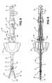
- FIG. 7is a cross sectional view of part of the tool cartridge of the first embodiment showing a first grip and a first piston securing a first jaw connection wire;
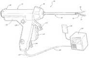
- the handle assembly 22includes a housing 25 .
- the tool cartridge 24is at least partially receivable in the housing 25 of the handle assembly 22 . That is, the housing 25 supports the tool cartridge 24 by interfacing with at least part of the tool cartridge 24 . Specifically, in the illustrated embodiments, part of the tool cartridge 24 is disposed inside the housing 25 and part of the tool cartridge 24 is disposed outside the housing 25 .
- the handle assembly 22is electrically connectable to a power source 120 via a cable 122 .
- the cable 122preferably includes a plurality of conductors 123 for conduction of electrical power and/or data between the handle assembly 22 and the power source 120 .
- the handle assembly 22 and/or the tool cartridge 24may also include an identification chip 150 .
- the identification chip 150is supported by the PCB 124 , as is shown in FIG. 16 .
- the chip 150contains identification data to identify the handle assembly 22 and/or tool cartridge 24 that is that is connected to the power source 120 .
- the identification datamay include a serial number, the particular tools 26 that the cartridge 24 carries, or other relevant information.
- the power source 120may track the serial numbers provided by the identification chip 150 to limit the number of uses of each particular tool cartridge 24 and/or handle assembly 22 .
- the power source 120may also launch an initial default setup to accommodate the characteristics of the specific tool cartridge 24 and/or apparatus 20 .
Landscapes
- Health & Medical Sciences (AREA)
- Surgery (AREA)
- Engineering & Computer Science (AREA)
- Life Sciences & Earth Sciences (AREA)
- Biomedical Technology (AREA)
- Otolaryngology (AREA)
- Nuclear Medicine, Radiotherapy & Molecular Imaging (AREA)
- Plasma & Fusion (AREA)
- Physics & Mathematics (AREA)
- Heart & Thoracic Surgery (AREA)
- Medical Informatics (AREA)
- Molecular Biology (AREA)
- Animal Behavior & Ethology (AREA)
- General Health & Medical Sciences (AREA)
- Public Health (AREA)
- Veterinary Medicine (AREA)
- Surgical Instruments (AREA)
Abstract
Description
Claims (19)
Priority Applications (1)
| Application Number | Priority Date | Filing Date | Title |
|---|---|---|---|
| US12/715,823US8647342B2 (en) | 2009-03-02 | 2010-03-02 | Surgical apparatus for tissue sealing and cutting |
Applications Claiming Priority (2)
| Application Number | Priority Date | Filing Date | Title |
|---|---|---|---|
| US15664309P | 2009-03-02 | 2009-03-02 | |
| US12/715,823US8647342B2 (en) | 2009-03-02 | 2010-03-02 | Surgical apparatus for tissue sealing and cutting |
Publications (2)
| Publication Number | Publication Date |
|---|---|
| US20100292690A1 US20100292690A1 (en) | 2010-11-18 |
| US8647342B2true US8647342B2 (en) | 2014-02-11 |
Family
ID=42709978
Family Applications (1)
| Application Number | Title | Priority Date | Filing Date |
|---|---|---|---|
| US12/715,823Active2032-07-31US8647342B2 (en) | 2009-03-02 | 2010-03-02 | Surgical apparatus for tissue sealing and cutting |
Country Status (3)
| Country | Link |
|---|---|
| US (1) | US8647342B2 (en) |
| EP (1) | EP2403422B1 (en) |
| WO (1) | WO2010101897A1 (en) |
Cited By (7)
| Publication number | Priority date | Publication date | Assignee | Title |
|---|---|---|---|---|
| WO2017059228A1 (en) | 2015-10-02 | 2017-04-06 | Elucent Medical, Inc. | Signal tag detection components, devices, and systems |
| US9730764B2 (en) | 2015-10-02 | 2017-08-15 | Elucent Medical, Inc. | Signal tag detection components, devices, and systems |
| US10154799B2 (en) | 2016-08-12 | 2018-12-18 | Elucent Medical, Inc. | Surgical device guidance and monitoring devices, systems, and methods |
| US10278779B1 (en) | 2018-06-05 | 2019-05-07 | Elucent Medical, Inc. | Exciter assemblies |
| US11344382B2 (en) | 2014-01-24 | 2022-05-31 | Elucent Medical, Inc. | Systems and methods comprising localization agents |
| EP4302720A2 (en) | 2015-10-02 | 2024-01-10 | Elucent Medical, Inc. | Signal tag detection systems |
| US12210920B2 (en) | 2020-09-16 | 2025-01-28 | Elucent Medical, Inc. | Systems and methods comprising linked localization agents |
Families Citing this family (37)
| Publication number | Priority date | Publication date | Assignee | Title |
|---|---|---|---|---|
| US9572621B2 (en) | 2009-06-02 | 2017-02-21 | Bovie Medical Corporation | Surgical jaws for sealing tissue |
| US9039691B2 (en) | 2012-06-29 | 2015-05-26 | Covidien Lp | Surgical forceps |
| US9072524B2 (en) | 2012-06-29 | 2015-07-07 | Covidien Lp | Surgical forceps |
| US9375205B2 (en) | 2012-11-15 | 2016-06-28 | Covidien Lp | Deployment mechanisms for surgical instruments |
| US10772674B2 (en)* | 2012-11-15 | 2020-09-15 | Covidien Lp | Deployment mechanisms for surgical instruments |
| JP6141506B2 (en) | 2013-03-15 | 2017-06-07 | ジャイラス エーシーエムアイ インク | Combined electrosurgical device |
| WO2014143472A1 (en) | 2013-03-15 | 2014-09-18 | GYRUS ACMI, INC. (d/b/a OLYMPUS SURGICAL TECHNOLOGIES AMERICA) | Electrosurgical instrument |
| CN105142556B (en) | 2013-03-15 | 2019-01-08 | 捷锐士阿希迈公司(以奥林巴斯美国外科技术名义) | Bias surgical clamp |
| JP6153654B2 (en) | 2013-03-15 | 2017-06-28 | ジャイラス エーシーエムアイ インク | Combined electrosurgical device |
| CN105380711B (en) | 2013-03-15 | 2018-01-02 | 捷锐士阿希迈公司(以奥林巴斯美国外科技术名义) | Combine electrosurgery device |
| US9713492B2 (en) | 2013-09-03 | 2017-07-25 | Covidien Lp | Switch assemblies for multi-function surgical instruments and surgical instruments incorporating the same |
| US9597141B2 (en) | 2013-09-03 | 2017-03-21 | Covidien Lp | Switch assemblies for multi-function surgical instruments and surgical instruments incorporating the same |
| DE102013110595A1 (en)* | 2013-09-25 | 2015-04-09 | Aesculap Ag | HF surgical instrument |
| US10231776B2 (en) | 2014-01-29 | 2019-03-19 | Covidien Lp | Tissue sealing instrument with tissue-dissecting electrode |
| WO2016028835A1 (en) | 2014-08-20 | 2016-02-25 | GYRUS ACMI, INC. (d/b/a OLYMPUS SURGICAL TECHNOLOGIES AMERICA) | Surgical forceps and latching system |
| US9987076B2 (en) | 2014-09-17 | 2018-06-05 | Covidien Lp | Multi-function surgical instruments |
| US9877777B2 (en) | 2014-09-17 | 2018-01-30 | Covidien Lp | Surgical instrument having a bipolar end effector assembly and a deployable monopolar assembly |
| US10039592B2 (en) | 2014-09-17 | 2018-08-07 | Covidien Lp | Deployment mechanisms for surgical instruments |
| US9918785B2 (en) | 2014-09-17 | 2018-03-20 | Covidien Lp | Deployment mechanisms for surgical instruments |
| US10080605B2 (en) | 2014-09-17 | 2018-09-25 | Covidien Lp | Deployment mechanisms for surgical instruments |
| US9724153B2 (en) | 2014-11-17 | 2017-08-08 | Covidien Lp | Deployment mechanisms for surgical instruments |
| US9867656B2 (en) | 2014-11-17 | 2018-01-16 | Covidien Lp | Multi-function surgical instruments |
| US9814517B2 (en) | 2014-11-17 | 2017-11-14 | Covidien Lp | Deployment mechanisms for multi-function surgical instruments |
| US9687294B2 (en) | 2014-11-17 | 2017-06-27 | Covidien Lp | Deployment mechanism for surgical instruments |
| US9687293B2 (en) | 2014-11-17 | 2017-06-27 | Covidien Lp | Deployment mechanism for surgical instruments |
| US9814516B2 (en) | 2014-11-17 | 2017-11-14 | Covidien Lp | Deployment mechanisms for multi-function surgical instruments |
| US10478245B2 (en) | 2014-12-10 | 2019-11-19 | Covidien Lp | Energizable attachment for surgical devices |
| USD844138S1 (en) | 2015-07-17 | 2019-03-26 | Covidien Lp | Handle assembly of a multi-function surgical instrument |
| USD844139S1 (en) | 2015-07-17 | 2019-03-26 | Covidien Lp | Monopolar assembly of a multi-function surgical instrument |
| US10537381B2 (en) | 2016-02-26 | 2020-01-21 | Covidien Lp | Surgical instrument having a bipolar end effector assembly and a deployable monopolar assembly |
| US11154348B2 (en) | 2017-08-29 | 2021-10-26 | Covidien Lp | Surgical instruments and methods of assembling surgical instruments |
| US10667834B2 (en) | 2017-11-02 | 2020-06-02 | Gyrus Acmi, Inc. | Bias device for biasing a gripping device with a shuttle on a central body |
| US11383373B2 (en) | 2017-11-02 | 2022-07-12 | Gyms Acmi, Inc. | Bias device for biasing a gripping device by biasing working arms apart |
| US11298801B2 (en) | 2017-11-02 | 2022-04-12 | Gyrus Acmi, Inc. | Bias device for biasing a gripping device including a central body and shuttles on the working arms |
| US11123132B2 (en) | 2018-04-09 | 2021-09-21 | Covidien Lp | Multi-function surgical instruments and assemblies therefor |
| US10828756B2 (en) | 2018-04-24 | 2020-11-10 | Covidien Lp | Disassembly methods facilitating reprocessing of multi-function surgical instruments |
| US11896291B2 (en) | 2018-07-02 | 2024-02-13 | Covidien Lp | Electrically-insulative shafts, methods of manufacturing electrically-insulative shafts, and energy-based surgical instruments incorporating electrically-insulative shafts |
Citations (18)
| Publication number | Priority date | Publication date | Assignee | Title |
|---|---|---|---|---|
| US5226908A (en) | 1989-12-05 | 1993-07-13 | Inbae Yoon | Multi-functional instruments and stretchable ligating and occluding devices |
| WO1995007662A1 (en) | 1993-09-14 | 1995-03-23 | Microsurge, Inc. | Endoscopic surgical instrument with guided jaws and ratchet control |
| US5443479A (en) | 1994-02-07 | 1995-08-22 | Bressi, Jr.; Thomas E. | Surgical forceps |
| US5507297A (en) | 1991-04-04 | 1996-04-16 | Symbiosis Corporation | Endoscopic instruments having detachable proximal handle and distal portions |
| US5603723A (en)* | 1995-01-11 | 1997-02-18 | United States Surgical Corporation | Surgical instrument configured to be disassembled for cleaning |
| US5611808A (en) | 1995-09-12 | 1997-03-18 | Cabot Technology Corporation | Blade assembly receptacle and method |
| US5800449A (en) | 1997-03-11 | 1998-09-01 | Ethicon Endo-Surgery, Inc. | Knife shield for surgical instruments |
| US5820630A (en)* | 1996-10-22 | 1998-10-13 | Annex Medical, Inc. | Medical forceps jaw assembly |
| US6099550A (en) | 1989-12-05 | 2000-08-08 | Yoon; Inbae | Surgical instrument having jaws and an operating channel and method for use thereof |
| US6270497B1 (en) | 1998-08-27 | 2001-08-07 | Olympus Optical Co., Ltd. | High-frequency treatment apparatus having control mechanism for incising tissue after completion of coagulation by high-frequency treatment tool |
| US20030191464A1 (en) | 2002-04-09 | 2003-10-09 | Pentax Corporation | Endoscopic forceps instrument |
| US6679882B1 (en)* | 1998-06-22 | 2004-01-20 | Lina Medical Aps | Electrosurgical device for coagulating and for making incisions, a method of severing blood vessels and a method of coagulating and for making incisions in or severing tissue |
| EP1433428A1 (en) | 2002-08-02 | 2004-06-30 | Olympus Corporation | Ultrasonic treatment apparatus |
| US20040254573A1 (en)* | 2003-06-13 | 2004-12-16 | Dycus Sean T. | Vessel sealer and divider for use with small trocars and cannulas |
| EP1557132A1 (en) | 2004-01-26 | 2005-07-27 | Steve Livneh | A multi-mode surgical instrument |
| US20080015566A1 (en) | 2006-07-13 | 2008-01-17 | Steve Livneh | Surgical sealing and cutting apparatus |
| US20080154299A1 (en) | 2006-12-08 | 2008-06-26 | Steve Livneh | Forceps for performing endoscopic surgery |
| US20080208246A1 (en) | 2007-02-08 | 2008-08-28 | Steve Livneh | Modular electrosurgical adaptors and multi function active shafts for use in electrosurgical instruments |
- 2010
- 2010-03-02USUS12/715,823patent/US8647342B2/enactiveActive
- 2010-03-02WOPCT/US2010/025891patent/WO2010101897A1/enactiveApplication Filing
- 2010-03-02EPEP10749190.4Apatent/EP2403422B1/enactiveActive
Patent Citations (18)
| Publication number | Priority date | Publication date | Assignee | Title |
|---|---|---|---|---|
| US6099550A (en) | 1989-12-05 | 2000-08-08 | Yoon; Inbae | Surgical instrument having jaws and an operating channel and method for use thereof |
| US5226908A (en) | 1989-12-05 | 1993-07-13 | Inbae Yoon | Multi-functional instruments and stretchable ligating and occluding devices |
| US5507297A (en) | 1991-04-04 | 1996-04-16 | Symbiosis Corporation | Endoscopic instruments having detachable proximal handle and distal portions |
| WO1995007662A1 (en) | 1993-09-14 | 1995-03-23 | Microsurge, Inc. | Endoscopic surgical instrument with guided jaws and ratchet control |
| US5443479A (en) | 1994-02-07 | 1995-08-22 | Bressi, Jr.; Thomas E. | Surgical forceps |
| US5603723A (en)* | 1995-01-11 | 1997-02-18 | United States Surgical Corporation | Surgical instrument configured to be disassembled for cleaning |
| US5611808A (en) | 1995-09-12 | 1997-03-18 | Cabot Technology Corporation | Blade assembly receptacle and method |
| US5820630A (en)* | 1996-10-22 | 1998-10-13 | Annex Medical, Inc. | Medical forceps jaw assembly |
| US5800449A (en) | 1997-03-11 | 1998-09-01 | Ethicon Endo-Surgery, Inc. | Knife shield for surgical instruments |
| US6679882B1 (en)* | 1998-06-22 | 2004-01-20 | Lina Medical Aps | Electrosurgical device for coagulating and for making incisions, a method of severing blood vessels and a method of coagulating and for making incisions in or severing tissue |
| US6270497B1 (en) | 1998-08-27 | 2001-08-07 | Olympus Optical Co., Ltd. | High-frequency treatment apparatus having control mechanism for incising tissue after completion of coagulation by high-frequency treatment tool |
| US20030191464A1 (en) | 2002-04-09 | 2003-10-09 | Pentax Corporation | Endoscopic forceps instrument |
| EP1433428A1 (en) | 2002-08-02 | 2004-06-30 | Olympus Corporation | Ultrasonic treatment apparatus |
| US20040254573A1 (en)* | 2003-06-13 | 2004-12-16 | Dycus Sean T. | Vessel sealer and divider for use with small trocars and cannulas |
| EP1557132A1 (en) | 2004-01-26 | 2005-07-27 | Steve Livneh | A multi-mode surgical instrument |
| US20080015566A1 (en) | 2006-07-13 | 2008-01-17 | Steve Livneh | Surgical sealing and cutting apparatus |
| US20080154299A1 (en) | 2006-12-08 | 2008-06-26 | Steve Livneh | Forceps for performing endoscopic surgery |
| US20080208246A1 (en) | 2007-02-08 | 2008-08-28 | Steve Livneh | Modular electrosurgical adaptors and multi function active shafts for use in electrosurgical instruments |
Non-Patent Citations (4)
| Title |
|---|
| English language International Search Report for International Application No. PCT/US2010/025891, mailed Apr. 29, 2010; 2 pages. |
| European Search Report for European Application No. 10749190.4; dated Nov. 9, 2012; five (5) pages. |
| International Search Report and Written Opinion for International Application No. PCT/US2010/001607, mailed Aug. 2, 2010; 7 pages. |
| Written Opinion for International Application No. PCT/US2010/025891, mailed Apr. 29, 2010; 6 pages. |
Cited By (20)
| Publication number | Priority date | Publication date | Assignee | Title |
|---|---|---|---|---|
| US11344382B2 (en) | 2014-01-24 | 2022-05-31 | Elucent Medical, Inc. | Systems and methods comprising localization agents |
| EP4302720A2 (en) | 2015-10-02 | 2024-01-10 | Elucent Medical, Inc. | Signal tag detection systems |
| US11786333B2 (en) | 2015-10-02 | 2023-10-17 | Elucent Medical, Inc. | Signal tag detection components, devices, and systems |
| US12245902B2 (en) | 2015-10-02 | 2025-03-11 | Elucent Medical, Inc. | Signal tag detection components, devices, and systems |
| WO2017059228A1 (en) | 2015-10-02 | 2017-04-06 | Elucent Medical, Inc. | Signal tag detection components, devices, and systems |
| US10245119B2 (en) | 2015-10-02 | 2019-04-02 | Elucent Medical, Inc. | Signal tag detection components, devices, and systems |
| US10245118B2 (en) | 2015-10-02 | 2019-04-02 | Elucent Medical, Inc. | Signal tag detection components, devices, and systems |
| US10751145B2 (en) | 2015-10-02 | 2020-08-25 | Elucent Medical, Inc. | Signal tag detection components, devices, and systems |
| US11135034B2 (en) | 2015-10-02 | 2021-10-05 | Elucent Medical, Inc. | Signal tag detection components, devices, and systems |
| US9987097B2 (en) | 2015-10-02 | 2018-06-05 | Elucent Medical, Inc. | Signal tag detection components, devices, and systems |
| US9730764B2 (en) | 2015-10-02 | 2017-08-15 | Elucent Medical, Inc. | Signal tag detection components, devices, and systems |
| US11298044B2 (en) | 2016-08-12 | 2022-04-12 | Elucent Medical, Inc. | Surgical device guidance and monitoring devices, systems, and methods |
| US10154799B2 (en) | 2016-08-12 | 2018-12-18 | Elucent Medical, Inc. | Surgical device guidance and monitoring devices, systems, and methods |
| US12357192B2 (en) | 2016-08-12 | 2025-07-15 | Elucent Medical, Inc. | Surgical device guidance and monitoring devices, systems, and methods |
| US10278779B1 (en) | 2018-06-05 | 2019-05-07 | Elucent Medical, Inc. | Exciter assemblies |
| US11540885B2 (en) | 2018-06-05 | 2023-01-03 | Elucent Medical, Inc. | Orthogonally isolated exciter with field steering |
| US11666391B2 (en) | 2018-06-05 | 2023-06-06 | Elucent Medical, Inc. | Exciter assemblies |
| US11185375B2 (en) | 2018-06-05 | 2021-11-30 | Elucent Medical, Inc. | Exciter assemblies |
| US12186029B2 (en) | 2018-06-05 | 2025-01-07 | Elucent Medical, Inc. | Exciter assemblies |
| US12210920B2 (en) | 2020-09-16 | 2025-01-28 | Elucent Medical, Inc. | Systems and methods comprising linked localization agents |
Also Published As
| Publication number | Publication date |
|---|---|
| US20100292690A1 (en) | 2010-11-18 |
| EP2403422A4 (en) | 2012-12-12 |
| WO2010101897A1 (en) | 2010-09-10 |
| EP2403422A1 (en) | 2012-01-11 |
| EP2403422B1 (en) | 2013-12-25 |
Similar Documents
| Publication | Publication Date | Title |
|---|---|---|
| US8647342B2 (en) | Surgical apparatus for tissue sealing and cutting | |
| CA2709916C (en) | Surgical apparatus with removable tool cartridge | |
| US8728076B2 (en) | Surgical apparatus with removable tool cartridge | |
| CN105380711B (en) | Combine electrosurgery device | |
| US9585714B2 (en) | Surgical sealing and cutting apparatus | |
| JP4225624B2 (en) | High frequency treatment device | |
| JP5336551B2 (en) | Bipolar forceps with monopolar extension | |
| CN104994802B (en) | Combined electrosurgical device | |
| JP5020916B2 (en) | Bipolar forceps having a monopolar extension | |
| AU2015266597B2 (en) | Bipolar electrosurgery actuator | |
| US6743230B2 (en) | Bipolar grasping instrument | |
| US6551313B1 (en) | Electrosurgical instrument with separate cutting and coagulating members | |
| US20230076952A1 (en) | Multi-function surgical instruments and selection assemblies for multi-function surgical instruments |
Legal Events
| Date | Code | Title | Description |
|---|---|---|---|
| AS | Assignment | Owner name:BOVIE MEDICAL CORPORATION, FLORIDA Free format text:ASSIGNMENT OF ASSIGNORS INTEREST;ASSIGNOR:LIVNEH, STEVE;REEL/FRAME:024770/0172 Effective date:20100727 | |
| AS | Assignment | Owner name:BOVIE MEDICAL CORPORATION, FLORIDA Free format text:CORRECTIVE ASSIGNMENT TO CORRECT THE ASSIGNEE ADDRESS PREVIOUSLY RECORDED ON REEL 024770 FRAME 0172. ASSIGNOR(S) HEREBY CONFIRMS THE THE CORRECTION OF THE RECEIVING PARTY ADDRESS TO 5115 ULMERTON ROAD, CLEARWATER, FLORIDA 33760-4004;ASSIGNOR:LIVNEH, STEVE;REEL/FRAME:024802/0589 Effective date:20100727 | |
| FEPP | Fee payment procedure | Free format text:PAT HOLDER CLAIMS SMALL ENTITY STATUS, ENTITY STATUS SET TO SMALL (ORIGINAL EVENT CODE: LTOS); ENTITY STATUS OF PATENT OWNER: SMALL ENTITY | |
| STCF | Information on status: patent grant | Free format text:PATENTED CASE | |
| FPAY | Fee payment | Year of fee payment:4 | |
| AS | Assignment | Owner name:APYX MEDICAL CORPORATION, FLORIDA Free format text:CHANGE OF NAME;ASSIGNOR:BOVIE MEDICAL CORPORATION;REEL/FRAME:049166/0464 Effective date:20190109 | |
| MAFP | Maintenance fee payment | Free format text:PAYMENT OF MAINTENANCE FEE, 8TH YR, SMALL ENTITY (ORIGINAL EVENT CODE: M2552); ENTITY STATUS OF PATENT OWNER: SMALL ENTITY Year of fee payment:8 | |
| AS | Assignment | Owner name:MIDCAP FUNDING IV TRUST, MARYLAND Free format text:SECURITY INTEREST;ASSIGNOR:APYX MEDICAL CORPORATION;REEL/FRAME:062913/0001 Effective date:20230217 | |
| AS | Assignment | Owner name:PERCEPTIVE CREDIT HOLDINGS IV, LP, AS ADMINISTRATIVE AGENT, NEW YORK Free format text:SECURITY INTEREST;ASSIGNOR:APYX MEDICAL CORPORATION;REEL/FRAME:065523/0013 Effective date:20231108 | |
| AS | Assignment | Owner name:APYX MEDICAL CORPORATION, FLORIDA Free format text:RELEASE BY SECURED PARTY;ASSIGNOR:MIDCAP FUNDING IV TRUST;REEL/FRAME:065612/0105 Effective date:20231108 | |
| MAFP | Maintenance fee payment | Free format text:PAYMENT OF MAINTENANCE FEE, 12TH YR, SMALL ENTITY (ORIGINAL EVENT CODE: M2553); ENTITY STATUS OF PATENT OWNER: SMALL ENTITY Year of fee payment:12 |