US8647310B2 - Medical connector with closeable luer connector - Google Patents
Medical connector with closeable luer connectorDownload PDFInfo
- Publication number
- US8647310B2 US8647310B2US13/100,508US201113100508AUS8647310B2US 8647310 B2US8647310 B2US 8647310B2US 201113100508 AUS201113100508 AUS 201113100508AUS 8647310 B2US8647310 B2US 8647310B2
- Authority
- US
- United States
- Prior art keywords
- luer
- connector
- luer tip
- tip
- male luer
- Prior art date
- Legal status (The legal status is an assumption and is not a legal conclusion. Google has not performed a legal analysis and makes no representation as to the accuracy of the status listed.)
- Active, expires
Links
Images


Classifications
- A—HUMAN NECESSITIES
- A61—MEDICAL OR VETERINARY SCIENCE; HYGIENE
- A61M—DEVICES FOR INTRODUCING MEDIA INTO, OR ONTO, THE BODY; DEVICES FOR TRANSDUCING BODY MEDIA OR FOR TAKING MEDIA FROM THE BODY; DEVICES FOR PRODUCING OR ENDING SLEEP OR STUPOR
- A61M39/00—Tubes, tube connectors, tube couplings, valves, access sites or the like, specially adapted for medical use
- A61M39/22—Valves or arrangement of valves
- A61M39/26—Valves closing automatically on disconnecting the line and opening on reconnection thereof
- A61M2039/261—Valves closing automatically on disconnecting the line and opening on reconnection thereof where the fluid space within the valve is increasing upon disconnection
- A—HUMAN NECESSITIES
- A61—MEDICAL OR VETERINARY SCIENCE; HYGIENE
- A61M—DEVICES FOR INTRODUCING MEDIA INTO, OR ONTO, THE BODY; DEVICES FOR TRANSDUCING BODY MEDIA OR FOR TAKING MEDIA FROM THE BODY; DEVICES FOR PRODUCING OR ENDING SLEEP OR STUPOR
- A61M39/00—Tubes, tube connectors, tube couplings, valves, access sites or the like, specially adapted for medical use
- A61M39/22—Valves or arrangement of valves
- A61M39/26—Valves closing automatically on disconnecting the line and opening on reconnection thereof
- A61M2039/267—Valves closing automatically on disconnecting the line and opening on reconnection thereof having a sealing sleeve around a tubular or solid stem portion of the connector
- A61M2039/268—Valves closing automatically on disconnecting the line and opening on reconnection thereof having a sealing sleeve around a tubular or solid stem portion of the connector wherein the stem portion is moved for opening and closing the valve, e.g. by translation, rotation
Definitions
- Embodiments of this disclosurerelate generally to medical connectors through which fluids flow, and in particular, to medical connectors with male luers.
- female connectorsIn order to maintain a barrier to bacteria, debris, and fluid leakage, female connectors often have been provided with closures, such as septa, flexible seals, or other impediments, at their mating ends. When a male luer connector is engaged with the female connector, the closure of the female connector is temporarily opened, pierced, or moved to allow fluid to flow between the two connectors. Male connectors typically employ needles or luers to open, pierce, or move the closure on the female connectors.
- male luer connectorsare generally not provided with automatic closing mechanisms.
- Male luer connectorssometimes employ additional components, such as caps, to stop the flow of fluid and impede the entry of bacteria and debris. Because such closure mechanisms are not automatic (or not used at all), male luer connectors are sometimes left unsealed, allowing fluid to drip out. This may increase the risk of unsanitary conditions inside and outside of the fluid transfer system.
- the fluids in the tubing and connectorscan be harmful if released.
- male luer connectorsare often employed at the downstream end of gravity-fed fluid sources such as IV bags.
- fluid sourcessuch as IV bags.
- the connectors and tubingWhen the connectors and tubing are initially connected to such sources, they are generally empty (e.g., filled with air) and must be primed with fluid before they can be connected to a patient.
- the priming procedurefluid is allowed to flow from the upstream end of the tubing toward the male luer connector on the downstream end.
- the air in the tubingescapes through the male connector on the downstream end into the environment. Once the fluid itself reaches the male connector, it can also escape and spill out. Because male luer connectors do not usually close automatically after priming, the male luer often drips out a small amount of fluid as the male connector is rapidly moved into mating engagement with a female connector. For this reason, the male luer is generally held over a sink or trash can at the end of the priming procedure to contain the dripping fluid.
- closeable male luer connectorsautomatically open when engaged with a female connector and automatically close when disengaged from such connector or easily can be mechanically opened or closed to minimize or eliminate dripping during priming and other procedures and to improve the barrier of the fluid transfer system against bacteria and other debris.
- a closable male luercan be mechanically opened by a user without disrupting the mechanical connection between connectors (e.g., such as by unscrewing connections between housings) so as to minimize or eliminate dripping during priming and other procedures and to improve the barrier of the fluid system against bacteria and other debris, as well as to allow the user to more carefully control the timing of the opening of the closable male luer.
- a male luer connectorhas a main housing with first and second ends.
- the first end of the housingcan comprise a male luer and a shroud surrounding at least a portion of the male luer.
- the shroudcan include screw threads disposed on an internal wall thereof.
- a tubular valve member with a fluid pathwaycan be disposed within the housing.
- the valve membercan have a tip on its first end. In the region near the tip, one or more fluid holes can be positioned on the valve member so as to provide a fluid pathway there through.
- the tipcan be configured to abut snugly against an internal wall of the male luer in a region at or near the first end of the male luer.
- the valve membercan also have one or more struts that can be directed towards the first end.
- the strutscan extend axially through a portion of the housing, and the ends of the struts toward the first end can be positioned within a space between the male luer and the shroud on the first end of the housing.
- a length of medical tubingcan be connected to the connector. An end of the tubing can be attached to the second end of the connector by adhesive, welding, threading, or some other means.
- a resilient member formed from either a metal or an elastomeric materialcan be positioned with at least a portion within the housing and can bias the valve member toward the closed position.
- the tip of the valve memberIn the closed state or position, the tip of the valve member can be pressed into close contact with a portion of the internal wall on the first end of the male luer, and fluid flow from the medical tubing through the tubular valve member can be generally impeded. Fluid generally does not exit through the opening on the first end of the male luer because such opening can be blocked by the tip of the valve member.
- the resilient memberWhen a force is applied to move or displace the valve member from the housing, the resilient member can be stressed against its bias and the tip of the valve member can be displaced toward the open position.
- This displacing forcecan be applied automatically through the action of connecting the male luer to a female end of another medical implement.
- the female connectormakes contact with and exerts a force directed towards the second end against the struts of the valve member or against another portion of the valve member, such as the luer tip. This force can move a portion of the valve member towards the second end against the biasing force that can be directed towards the first end exerted by a resilient member.
- valve memberIn this opened state, fluid can be permitted to flow through the opposing holes, around the tip of the valve member, and out of the connector through the gap between the tip of the valve member and the internal wall on the first end of the male luer.
- the valve membercan be automatically advanced in the direction of the second end when the valve member contacts a fluid conduit (e.g., a conduit positioned within a female connector) as the male and female connectors are brought together.
- a fluid conduite.g., a conduit positioned within a female connector
- the resilient memberwhen the separating force is removed, for example, by releasing the manual grip on the housing and the tubing, or by detaching the female connector from the first end of the housing, the resilient member once again can urge the valve member to the closed position. This can cause the tip on the first end of the valve member to abut closely against a portion of the internal wall in a region near the first end of the male luer, and can impede fluid flow out of the valve.
- Such embodimentsgenerally include means for permitting or impeding fluid flow through a male luer on a connector, which can be automatically manipulated upon connection with a corresponding female connector.
- Such embodimentsalso include features and configurations that permit the female portion of the male luer connector to be coupled with a corresponding male luer portion of a male luer connector or other component such as a syringe.
- Some embodiments disclosed hereinrelate to a first arrangement of a luer connector having a housing having a hollow bore, a first end, and a second end.
- a male luer tipcan be supported by the housing, the male luer tip configured to rotate with respect to the housing.
- the male luer tipcan have a first open end and a passageway through the male luer tip in fluid communication with the first open end.
- the luer connectorcan have a substantially rigid internal member extending into the passageway of the male luer tip toward the first open end of the male luer tip.
- At least one of the male luer tip and the internal membercan be axially moveable between a first position and a second position relative to the other of the male luer tip and the internal member.
- the male luer tip and the internal membercan be configured to cooperate such that rotation of the male luer tip in a first direction relative to the housing increases an axial displacement between the first open end of the male luer tip and an end portion of the internal member.
- the end portion of the internal memberin the first position, can provide a substantially fluid-tight seal with respect to the first open end of the male luer tip so as to substantially prevent a flow of fluid through the male luer tip, and in the second position, the end portion of the internal member can be spaced apart from the first open end so that fluid is permitted to flow through the first open end of the male luer tip.
- the male luer tipcan be configured to rotate with respect to the housing as a female connector is threadedly connected to the luer connector.
- the male luer tip and the internal membercan cooperate such that rotation of the male luer tip in a second direction relative to the housing decreases the axial displacement between the first open end of the male luer tip and the end portion of the internal member.
- the internal membercan be axially moveable relative to the male luer tip, and can have a solid cross-section along at least a substantial portion of the length thereof such that at least a substantial amount of fluid flowing through the luer connector is required to flow around an outside surface of the internal member.
- Some arrangements of the internal membercan have an axial opening through at least a portion of the internal member, the axial opening being in fluid communication with the hollow bore of the housing and being configured to permit fluid to flow through the internal member.
- Some embodiments of the luer connector disclosed hereincan further have a chamber within the housing, the chamber being configured produce a change in volume as at least one of the male luer tip and the internal member axially moves between the first position and the second position relative to the other of the male luer tip and the internal member.
- the volume of the chambercan be larger when the male luer tip and the internal member are in the first position.
- Some arrangements of the internal membercan have a helical or angled surface, the helical or angled surface configured to cooperate with the male luer tip and to cause the change in axial displacement between the male luer tip and the internal member as the male luer tip is rotated.
- the luer connectorcan have a resilient member configured to bias the male luer tip and the internal member toward the first position.
- an opening in the first open end of the male luer tip and the end portion of the internal membercan have an ovular or other non-circular cross-sectional shape.
- the opening in the first open end of the male luer tipcan have a tapered internal wall portion and the end portion of the internal member can have a tapered external wall portion that cooperates with the internal wall portion of the male luer tip.
- the male luer tip and the internal membercan be configured such that relative rotation between the male luer tip and the internal member causes axial displacement between the male luer tip and the internal member.
- a luer connectorhaving a housing having a hollow bore, a first end, and a second end, a male luer tip supported by the housing configured to axially move with respect to the housing, the male luer tip having a first open end and a passageway through the male luer tip in fluid communication with the first open end, and a substantially rigid internal member extending into the passageway of the male luer tip toward the first open end of the male luer tip.
- the male luer tipcan be axially moveable between a first position and a second position relative to the internal member.
- an end portion of the internal memberin the first position, can provide a substantially fluid-tight seal with respect to the first open end of the male luer tip so as to substantially prevent a flow of fluid through the male luer tip, and in the second position, the end portion of the internal member can be spaced apart from the first open end so that fluid is permitted to flow through the first open end of the male luer tip.
- the male luer tipcan be configured to axially move from the first position to the second position as a female connector is threadedly connected to the luer connector.
- the internal membercan have a solid cross-section along at least a substantial portion of the length thereof such that at least a substantial amount of fluid flowing through the luer connector is required to flow around an outside surface of the internal member.
- the internal membercan have an axial opening through at least a portion of the internal member, the axial opening being in fluid communication with the hollow bore of the housing and being configured to permit fluid to flow through the internal member.
- the luer connectorcan further have a resilient member configured to bias the male luer tip toward the first position.
- a luer connectorhaving a housing having a hollow bore, a first end, and a second end, a male luer tip supported by the housing configured to rotate with respect to the housing, the male luer tip having an opening in a first end thereof and a passageway through the male luer tip in fluid communication with the opening in the first end thereof.
- the luer connectorcan have an internal member extending into the passageway of the male luer tip toward the opening in the first end thereof, the internal member having an opening in a first end thereof and a passageway through the internal member in fluid communication with the opening in the first end thereof.
- the male luer tipcan be configured to be rotatable between a first position and a second position relative to the internal member.
- the opening in the first end of the male luer tipcan be substantially offset with respect to the opening in the first end of the internal member so as to substantially prevent a flow of fluid through the male luer tip, and, in the second position, the opening in the first end of the male luer tip can be substantially aligned with respect to the opening in the first end of the internal member so that fluid is permitted to flow through the male luer tip.
- the male luer tipcan be configured to rotate in a first direction with respect to the housing from the first position to the second position as a female connector is threadedly connected to the luer connector, and/or to rotate in a second direction with respect to the housing from the second position to the first position as a female connector is threadedly disconnected from the luer connector.
- the internal membercan be rotationally fixed relative to the housing in some embodiments.
- the luer tipcan be biased toward the first position.
- the luer connectorcan be configured such that the male luer tip is prevented from rotating beyond the first or the second position.
- FIG. 1Ais a perspective view of an embodiment of a male luer connector attached to tubing configured to receive fluid from a hanging gravity-fed IV bag.
- the relative size of the connector and attached tubingis increased in comparison to other objects to facilitate viewing certain details.
- FIG. 1Bshows a perspective view of an embodiment of the male luer connector of FIG. 1A being connected to a female connector attached to tubing inserted into a patient.
- FIG. 2Ais a side view of the outside of the embodiment of the luer connector shown in FIG. 1A .
- FIG. 2Bis a cross-sectional view of the connector taken along the line 2 B- 2 B in FIG. 2A in a closed position.
- FIG. 2Cis a cross-sectional view the connector taken along the line 2 B- 2 B in FIG. 2A in an open position.
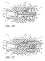
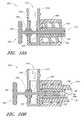
- FIG. 3Ais a cross-sectional view of another embodiment of a luer connector in a closed position.
- FIG. 3Bis a cross-sectional view of the connector in FIG. 3A in an open position.
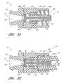
- FIG. 4Ais a cross-sectional view of another embodiment of a luer connector in a closed position.
- FIG. 4Bis a cross-sectional view of the connector in FIG. 4A in an open position.
- FIG. 4Cis a perspective view of an embodiment of a luer tip of the embodiment of the luer connector shown in FIG. 4A .
- FIG. 4Dis a side view of the embodiment of the luer tip shown in FIG. 4C .
- FIG. 4Eis a perspective view of an embodiment of a valve tube of the embodiment of the luer connector shown in FIG. 4A .
- FIG. 4Fis a side view of the embodiment the valve tube shown in FIG. 4E .
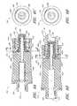
- FIG. 5Ais a cross-sectional view of another embodiment of a luer connector in a closed position.
- FIG. 5Bis an end view of the embodiment of the luer connector shown in FIG. 5A in a closed position.
- FIG. 5Cis an end view of the embodiment of the luer connector shown in FIG. 5A , showing the embodiment of the luer connector in an open position.
- FIG. 5Dis a cross-sectional view of the embodiment of the luer connector shown in FIG. 5A taken through line 5 D- 5 D in FIG. 5C .
- FIG. 5Eis a cross-sectional view of the embodiment of the luer connector shown in FIG. 5A taken through line 5 E- 5 E in FIG. 5C .
- FIG. 5Fis a perspective view of a portion of an embodiment of a valve tube of the embodiment of the luer connector shown in FIG. 5A .
- FIG. 6Ais a cross-sectional view of another embodiment of a luer connector in a closed position.
- FIG. 6Bis a cross-sectional view of the embodiment of the luer connector shown in FIG. 6A in an open position.
- FIG. 6Cis an end view of the embodiment of the luer connector shown in FIG. 6A in a closed position.
- FIG. 6Dis an end view of the embodiment of the luer connector shown in FIG. 6B in an open position.
- FIG. 6Eis a perspective view of an embodiment of a luer tip of the embodiment of the luer connector shown in FIG. 6A .
- FIG. 6Fis a cross-sectional view of the embodiment of the luer connector shown in FIG. 6A taken through line 6 F- 6 F and in FIG. 6A .
- FIG. 6Gis a cross-sectional view of the embodiment of the luer connector shown in FIG. 6A taken through line 6 G- 6 G and in FIG. 6B .
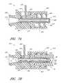
- FIG. 7Ais a cross-sectional view of another embodiment of a luer connector in a closed position.
- FIG. 7Bis a cross-sectional view of the embodiment of the luer connector shown in FIG. 7A in an open position.
- FIG. 8Ais a cross-sectional view of another embodiment of a luer connector in a closed position.
- FIG. 8Bis a cross-sectional view of the embodiment of the luer connector shown in FIG. 8A in an open position.
- FIG. 9Ais a cross-sectional view of another embodiment of a luer connector in a closed position.
- FIG. 9Bis a cross-sectional view of the embodiment of the luer connector shown in FIG. 9A in an open position.
- FIG. 10Ais a cross-sectional view of another embodiment of a luer connector in a closed position.
- FIG. 10Bis a cross-sectional view of the embodiment of the luer connector shown in FIG. 10A in an open position.
- FIG. 11Ais a cross-sectional view of another embodiment of a luer connector in a closed position.
- FIG. 11Bis a cross-sectional view of the embodiment of the luer connector shown in FIG. 11A in an open position.
- closing mechanismsfunction to substantially prevent and/or impede fluid from escaping from or entering into the male luer end of a connector, while allowing fluid flow when the male luer is manually opened or engaged with a corresponding female luer.
- terms such as “closed,” “sealed,” “prevent,” or “impede”should be understood as obstructions or barriers to fluid flow. These terms should not be understood to require that a particular structure or configuration achieves a complete fluid closure in all circumstances.
- Some medicationscan be harmful to a patient in certain applications. For example, exposure to the skin can sometimes result in a chemical burn. Inhalation of aerosolized forms of some medications also can be harmful. Thus, control over the containment of the medication is highly desirable.
- FIG. 1Ais a perspective view of an embodiment of a male luer connector attached to tubing configured to receive fluid from a hanging gravity-fed IV bag.
- the female end of the connectorcan alternatively be configured to engage a standard male luer end.
- FIG. 1Asome embodiments of a closeable male luer connector 10 is shown in a closed position.
- the luer connector 10can be attached to a gravity-fed IV bag 9 filled with fluid hanging from a pole stand 11 .
- a section of tubing 13can be attached.
- the opposite end of the tubing 13can be connected to the second end 14 of the luer connector 10 .
- a closing mechanism on the interior of the first end 12 of the luer connector 10can prevent the fluid contained within the bag 9 from flowing through the tubing 13 and leaking out of the luer connector 10 , as long as the luer connector 10 remains in a closed configuration.
- the IV delivery system illustrated in FIG. 1Acan be easily readied for fluid communication with a patient.
- the tubing 13can be filled with air when it is initially connected to the IV bag 9 . If the other end of the tubing 13 can be connected to a closed connector, as illustrated in FIG. 1A , the air cannot escape and fluid cannot enter the tubing 13 from the IV bag 9 .
- the luer connector 10can be changed so as to be in the open position until all of the air has been purged through the luer 10 and the fluid in the IV bag 9 fills the tubing 13 and connector 10 . This procedure is known as “priming.” As soon as the fluid line and connector are properly primed, the health care provider can then change the luer connector 10 to the closed position to stop the flow of fluid through the luer connector 10 .
- FIG. 1Bshows a perspective view of an embodiment of the male luer connector of FIG. 1A being connected to an exemplifying female connector attached to tubing inserted into a patient.
- a catheter 17has been inserted into a patient's arm 15 .
- the catheter 17penetrates the skin of the arm 15 and can be fluidly connected with the patient's bloodstream.
- the catheter 17can also be connected to a length of medical tubing 19 attached to a female medical connector 21 .
- the example of a female medical connector 21 illustrated in FIG. 1Bis a version of the Clave® connector manufactured by ICU Medical, Inc., San Clemente, Calif.
- Various embodiments of a connector of this typeare illustrated and described in U.S. Pat. No.
- FIGS. 1A-1BThe embodiment illustrated in FIGS. 1A-1B is described in further detail below.
- Each of the other embodiments disclosed hereincan be used in the illustrated fluid system, and in various modifications and alternatives thereof.
- the various embodiments of connectorscan be used in a wide variety of additional medical fluid systems.
- the disclosed connectorscan also be used to transfer bodily fluids such as blood, urine, or insulin, nourishing fluids, and/or therapeutic fluids such as fluids used in chemotherapy treatments.
- the disclosed connectorscan also be used to interconnect various other components of fluid transfer systems.
- FIG. 2Ais a side view of the outside of the embodiment of the luer connector 10 .
- FIGS. 2B and 2Care cross-sectional views of the luer connector 10 in a closed (or first) position and an open (or second) position, respectively.
- the valve member 20can be moved to the open position so as to not significantly impede the flow of fluid through the luer connector 10 .
- some embodiments of the assembled luer connector 10can comprise a housing 22 , a port member 24 positioned near the second end 14 of the luer connector 10 , a male luer or luer tip 26 positioned near the first end 12 of the luer connector 10 , a shroud 28 surrounding at least a portion of the luer tip 26 , and the valve member 20 mentioned above supported by the housing 22 .
- the housing 22can define a part line 25 , where the two or more separately formed portions of the housing can be joined.
- the port member 24can be joined with the housing 22 at the part line 25 using ultrasonic welding, epoxy, or other adhesive, interference fits, mechanical connections, unitary constructions, and/or any other suitable coupling method or methods.
- the port member 24 and the housing 22can be integrally formed, which may require the valve member 20 and the housing 22 to be configured differently to accommodate assembly of these and other components.
- the luer tip 26 , valve tube 32 , and sealing member 44can be assembled within the housing 22 through the shroud 28 at the first end 12 of the luer connector.
- a retaining member(not illustrated) that can be configured to retain the luer tip 26 and sealing member 44 in the desired position within the housing 22 can be assembled with the housing 22 after the other components have been assembled in the housing 22 .
- the retaining member(not illustrated) can be a planar disk having openings formed therein and configured to allow the luer tip 26 and struts 36 to translate axially relative to the retaining member.
- the retaining membercould be joined with the housing 22 using ultrasonic welding, epoxy, or other adhesive, interference fits, mechanical connections, and/or any other suitable coupling method or methods.
- valve base 34can be configured so that it is held in a fixed axial position adjacent to the port member 24 after the valve base 34 has been inserted into the housing 22 .
- the valve base 34can be configured so as to form an interference fit with the port member 24 when assembled therewith.
- the valve base 34can be attached to the port member 24 using ultrasonic welds, adhesive, mechanical connections such as tabs, channels, or protrusions, and/or by any other suitable coupling method or methods.
- Axial openings(not illustrated) can be formed in the valve base 34 or any similar components described herein to allow fluid or medicament to flow therethrough.
- valve base 34can be formed to abut flat against one more of the inside surfaces of the port member 24 .
- valve base 34 and valve tube 32can be integrally formed with the port member 24 , with the end portion 32 a of the valve tube 32 being configured to be attached to the valve tube 32 after the luer tip 26 has been assembled.
- the housing 22can be configured so that the luer tip 26 projects through an opening 40 formed in an internal wall 42 formed within the housing 22 .
- the luer connector 10can be configured so that the luer tip 22 translates axially relative to the opening 40 formed in the internal wall 42 .
- the valve member 20can comprise a tube 32 projecting from a valve base 34 toward the first end 12 of the connector 10 , and a pair of valve arms or struts 36 also preferably projecting from and supported by the second region 26 c of the male luer 26 .
- the valve struts 36can be positioned so as to be adjacent to the tip 26 along the sides of the tip 26 .
- a portion of the inner surface of the distal portion 32 a of the valve tube 32can be sealingly closed against the inner surface of a portion of the distal portion 26 a of the luer tip 26 such that fluid is generally prevented from flowing through the opening 38 formed in the distal end 26 a of the luer tip 26 .
- the opening 38preferably formed in the distal end portion 26 a of the luer tip 26 , or of any opening in any luer tip described herein: approximately 2 mm or less and approximately 0.5 mm to approximately 2.0 mm. Other diameters, either inside or outside the listed ranges can also be used.
- the opening 38can be any desired or otherwise suitable geometry. Regardless of the geometry of the opening 38 , the distal portion 32 a of the valve tube 32 can be sized appropriately to occupy the space in the opening 38 so that, when the luer connector 10 is in a closed position, a generally fluid tight seal is provided.
- the luer connector 10can be configured so that the tube 32 is supported in an axially fixed position relative to the housing 22 .
- the aft portion 34 a of the valve base 34can be supported indirectly or directly by the inside surface 24 a of the port member 24 .
- one or more substantially rigid tabs 50can be formed so as to project from the aft portion 34 a of the valve base 34 .
- the tabs 50can be configured to abut against the inside surface 24 a of the port member 24 .
- the valve base 34 and the tabs 50are preferably configured to allow fluid or medicament to flow freely around the valve base 34 .
- the luer tip 26can be slidably supported so as to translate axially relative to the valve tube 32 .
- valve struts 36that can be supported in a cantilevered disposition by the second end region 26 c of the male luer 26 can be configured so as to slide within the openings 48 formed through the internal wall 42 of the housing 22 .
- the number of openings 48 through the internal wall 42can be equal to the number of the valve struts 36 that are supported by the valve base 34 .
- An annular sealing member 44can be positioned between the outside surface of the luer tip 26 and the inside surface of the housing 22 so as to generally prevent any fluid from flowing through either of the openings 40 , 48 .
- the sealing member 44can be formed from a resilient material and configured to provide an axial biasing force on the luer tip 26 toward the first end 12 of the luer connector 10 , so as to bias the luer connector 10 to the closed position.
- the luer connector 10can be configured so that the sealing member 44 abuts against an aft surface 36 b of the valve struts 36 at a first end of the sealing member 44 (e.g., at the end of the sealing member 44 that is closer to the first end 12 of the luer connector 10 ).
- the luer connector 10can be configured so that the sealing member 44 abuts against an inside surface 24 b of the port member 24 at a second end of the sealing member 44 (e.g., the end of the sealing member 44 that is closer to the second end 14 of the luer connector 10 ).
- valve tube 32 or any other valve tube or valve member described with reference to any other embodiments hereincan be solid such that a substantial portion of the fluid flowing through the luer connector flows around the outside of the valve member.
- any luer connector embodiment disclosed hereincan be configured such that the valve tube is solid or such that the valve tube comprises an opening axially through at least a portion thereof.
- valve 20 , the valve base 34 , the valve struts 36 , and the protrusion 52can be integrally formed. In some embodiments, any of the features of the valve member 20 , including the valve tube 32 , the valve base 34 , the valve struts 36 , and the protrusion 52 , can be separately formed and adhered or otherwise joined together in subsequent manufacturing steps.
- the housing 22can generally be a tube-like structure with a passageway 54 that can extend away from the second end 14 of the connector 10 through the axial center of the luer connector 10 .
- fluidcan be permitted to flow from the second end 14 through the port member 24 , around the valve base 34 and the tube 32 , and out through the opening 38 in the luer tip 26 positioned at the first end 12 of the luer connector 10 .
- the port member 24 and the corresponding section of the fluid passageway 54can be sized and configured so as to accommodate a section of standard diameter medical tubing inserted therein, or so as to be joinable with any standard or suitably sized medical connector or component, in particular medical implements corresponding to ISO and/or ANSI standards.
- the length of the housing 22 (or any housing described herein) from the second end 14 to the distal end of the luer tip 26can be approximately 0.75 inch. However, the size of the housing 22 is not so confined. In some embodiments, the length of the housing 22 (or any housing described herein) from the second end 14 to the distal end of the luer tip 26 can be from approximately 0.5 inch to approximately 0.75 inch, or from approximately 0.75 inch to approximately 1.0 inch, or from approximately 1.0 inch to approximately 1.5 inches or more, or from or to any value within these ranges.
- the housing 22can be, but is not necessarily, less than or equal to approximately 1.5 inches from the second end 14 to the distal end of the luer tip 26 so that the weight and bulk of the connector can be minimized.
- the housing 22can have any length suited for a particular application.
- the shroud 28can have inner threads 56 on an interior wall to securely attach the connector 10 in a removable manner to another medical implement.
- the shroud 28can include other structures or materials for providing a releasable connection, including quick-release mechanisms and other means.
- the housing 22 and shroud 28can define a plurality of protrusions 58 or other suitable features on an outer surface to assist the user in firmly grasping and twisting the shroud 28 and the housing 22 with the user's fingers so as to prevent the luer connector 10 from slipping within the user's grasp when the luer connector 10 is twisted.
- the housing 22 or shroud 28may alternatively or additionally define depressions that have upwardly tapering sidewalls that prevent the fingers from sliding off the connector 10 , or any other features or materials that prevent the fingers from sliding relative to the connector 10 .
- the protrusions 58may extend around substantially the entire outer surface of the housing 22 or shroud 28 so that the user's fingers, when positioned on opposite sides of the connector 10 , will likely encounter a depression, regardless of the orientation of the connector 10 , during use.
- the tip 26can have a tapered external wall.
- the diameter of the luer tip 26can become gradually smaller from the valve base 34 towards the distal end portion 26 a of the tip 26 .
- the tip 26can define an opening 38 positioned at the distal end portion 26 a of the luer tip 26 .
- an interior space 60Near the base of the luer tip 26 , which can be the internal wall 42 , an interior space 60 (most clearly shown in FIG. 2B ) can communicate with the fluid passageway 54 of the luer connector 10 and with the opening 38 so as to provide a fluid flow path through the entire luer connector 10 .
- the term fluid passagewayis meant to refer to the entire fluid pathway through the luer connector.
- the dimensions of the housing, shroud, luer tip, or port member (e.g., the male and female ends) or other interfacescan be made to comply with applicable standards and/or regulations, such as the ANSI standards and or ISO standards.
- the distal end portion 32 a of the tube 32can be configured so as to complement the size and shape of the distal end portion 26 a of the luer tip 26 so as to define a sealable closing mechanism.
- the inside surface 26 b of the luer tip 26in the closed position, can be positioned against the outside surface 32 b of the valve tube 32 so as to provide a generally fluid-tight seal that prevents fluid or other medicament from pass through the opening 38 that can be formed in the distal end 26 a of the luer tip 26 .
- the closing mechanismcan be adapted to close the fluid passage extending through the closeable male luer 10 from fluid communication with the external environment, preferably whenever the male luer 10 is not engaged with a female connector.
- closurecan be formed at or near the first end 12 of the male luer 10 .
- the distal end portion 32 a of the tube 32can be made from, or covered by, a different material than is used to form the tube 32 .
- the distal end portion 32 acan be covered with a softer, more malleable or deformable material that may exhibit better sealing properties as compared to the material used to form the tube 32 so as to provide a better seal between the distal end portion 32 a of the tube 32 and the luer tip 26 .
- valve member 20can be constructed without a fluid path and function as a blocking plunger for fluid flowing around the valve member 20 rather than a means for conveying fluid between the first and second ends of the luer connector 10 .
- the housing 22 of the illustrated embodiment, or the housing of any embodiment described herein, the port member 24 , and any other components disclosed hereincan be constructed from any of a number of different materials or combination of materials.
- the housing 22 or any housing described hereincan be constructed from a relatively rigid material, such as polycarbonate or other polymeric material.
- the housing 22 , port member 24 , and/or the valve member of any embodiment described herein, or any of the components of this or any other embodimentcan also be constructed of a hydrophobic material, such as Bayer Makrolon, or any other suitable material.
- the length of the valve member 20can be shorter than the length of the housing 22 , but the length of the valve member 20 is not so limited. Any of the valve assemblies described herein, including but not limited to the valve member 20 , can be manufactured through injection molding. Finally, although the valve member 20 of the illustrated embodiment is configured as shown in FIGS. 2B-2C , many other configurations are possible.
- one or more protrusions or raised tabs 66can be formed on an exterior surface 24 a of the port member 24 to facilitate removably attaching a medical implement (not shown) with the second end 14 of the valve member 20 .
- the exterior surface 24 acan be cylindrical except for the protrusions, raised tabs, or other features formed thereon.
- the interior surface of the port member 24can be conically shaped, such that the diameter of the interior surface can be greatest at the portion of the interior surface adjacent to the second end 14 of the luer connector 10 .
- the internal taper of the interior surfacecan compliment and closely fit with the taper of a typical male luer. Such an internal taper can conform to ANSI and/or ISO standards and/or regulations, such as the standard for medical syringes.
- the outside surface 26 c of the luer tip 26can be straight or tapered so as to conform to ANSI and/or ISO standards and/or regulations, such as the standard for medical syringes.
- the inside surface of the luer tip 26 and the outside surface of the tube 32can either be straight or can also be tapered. Tapering the inside surface of the luer tip 26 and the outside surface of the tube 32 can help minimize the amount of fluid that flows into and is trapped in the interior space 60 between the tube 32 in the luer tip 26 , since, as the tube 32 moves toward a closed position, the distance between the tapered inside surface of the luer tip 26 and the outside surface of the tube 32 would be reduced.
- the closeable luer connector 10can have a female mating end at the second end 14 of the luer connector 10 and a male luer mating end at the first end 12 of the luer connector 10 .
- the closeable female connector 21 of FIG. 1B(referenced above), as well as other standard female connectors with similar external structure, can also have both female and male ends.
- such female connectorscan utilize seals or other fluid barriers to impede the flow of fluid on the female end but do not typically do so on the male end.
- the female end of any of the closeable male luer connectors disclosed hereincan be configured to include a closeable female end.
- the structure for selective fluid-impedance with the female connector 21could be included within the female end of any of the closeable male luer connectors disclosed herein to provide a connector that selectively seals or impedes fluid flow on both ends.
- a resilient seal elementit can be advantageous for a resilient seal element to be positioned at or near the female opening, as shown in U.S. Pat. No. 5,685,866 entitled Medical Valve and Method of Use filed on Nov. 4, 1994 which disclosure is hereby incorporated by reference as if fully set forth herein.
- seal elementBy positioning the seal element in this manner, it is possible to cleanse the female opening prior to use with antiseptic with a wiping motion to avoid a harmful accumulation of debris, bacteria, antiseptic, or other unwanted substances on the seal element and/or in the region between the seal element and the housing of the connector adjacent to the seal element.
- the sealing member 44can define a generally cylindrical cross-section, as illustrated in FIGS. 2B and 2C .
- the sealing member 44can define a generally circular cross-section.
- the sealing membercan be substantially cylindrical and can have a bore extending axially through the center thereof.
- the sealing membercan further comprise a pair of generally rectangular protrusions extending from the sidewalls of the cylindrical portion at diametrically opposed positions.
- the protrusionscan have different shapes and/or positions, and can assist with positioning and/or aligning the sealing member in the desired position.
- the sealing member 44can also have a generally smaller-diameter middle portion surrounded by two rings at either end with larger diameters.
- the sealing membercan be constructed from a number of different materials.
- the sealing membercan be made from a silicon-based deformable material. Silicon-based deformable materials are among those that can form fluid-tight closures with plastics and other rigid polymeric materials.
- FIG. 2Cis a cross-sectional view of the luer connector 10 in an open position, so that fluid can be generally permitted to flow through the luer connector 10 .
- the flow of fluid or medicament through the luer connector 10is represented by arrows in FIG. 2C .
- the housing 22 , the valve member 20 , and the sealing member 44are in an assembled configuration.
- the valve member 20has preferably been moved to the open position by the insertion of the female connector 76 .
- FIG. 2Cillustrates a cross-section and embodiment of the luer connector 10 wherein the valve member 20 has preferably been caused to be opened by the insertion of an exemplifying female connector 76 .
- the female connector 76can comprise an elongate body 78 having a fluid passageway 80 therethrough, and the female connector 76 can have a tip 82 near its proximal end. In some embodiments, the tip 82 of the female connector 76 can have a radially extending surface 84 disposed on its external surface.
- the female connector 76can have a fluid conduit (not shown) within the female connector 76 . The fluid conduit is not included or required in all female connectors compatible with the connectors 10 disclosed herein.
- the fluid passageway 80can be tapered such that the diameter of the fluid passageway 80 decreases in the distal direction.
- the struts 36 of the valve member 20can extend through openings 48 in the internal wall 42 of the housing 22 such that, in the closed position, the ends of the struts 36 extend past the internal wall 42 toward the first end 12 of the connector 10 .
- the struts 36can be configured to engage the proximal end 84 of the female connector 76 as the female connector 76 advances into engagement with the closeable male luer 10 .
- the radially extending surface or surfaces 84 of the female connector 76can be threaded into the inner threads 56 of the male luer 10 .
- the two luers 10 , 76can be threadedly engaged with one another until the taper of the inner surface 86 of the female luer connector 76 lies adjacent the correspondingly tapered external surface 26 c of the tip 26 .
- the proximal end 84 of the tip of the female connector 76can contact the struts 36 of the valve member 20 .
- the struts 36 , and thereby the luer tip 26can be moved toward the second end 14 of the male connector 10 by the female connector 76 .
- the distal end portion 26 a of the luer tip 26can move away from the interior distal end portion 32 a of the valve tube 32 in the direction of the second end 14 of the male connector 10 .
- a space or gapcan form between the luer tip 26 and the valve tube 32 , permitting fluid to pass through the opening 38 into the fluid passageway 80 of the female connector 76 , or vice versa.
- the seal 44can compress, causing the seal 44 to exert a biasing force on the luer tip 26 toward the closed position or causing the seal 44 to increase the biasing force that this seal 44 exerts on the luer tip 26 .
- the biasing force from the seal 44can be resisted by the radially extending surface 84 of the female connector 76 contacting the inner threads 56 of the housing 22 .
- the seal 44can return the sealing portion of the luer tip 26 to the closed position around the valve tube 32 .
- the sealing member 44can be configured to maintain a fluid barrier between the outer surface of the tube 32 and the inner surface of the luer tip 26 .
- the sealing member 44comprises the generally rectangular protrusions the position of the sealing member 44 can be maintained by the protrusions.
- the sealing member 44can be positioned by adhering the outer surface of the protrusions to an inner surface of the luer tip 26 .
- the sealing member 44can be positioned by adhering the outer surface of the seal 44 to an inner surface of the luer tip 26 or to an outer surface of the valve tube 32 .
- Other suitable means of fixing the position of the sealing member 44can also be used.
- the fluid passageway 80 of the female connector 76can communicate with the passageway 54 of the valve member 20 so as to allow fluid to flow through the passageway 54 and the fluid passageway 80 of the female connector 76 in either direction. Fluid can thereby flow from tubing (not shown) or another connector or conduit that can be attached to second end 14 of the luer connector 10 , into the passageway 54 of the housing 22 , around the valve base 34 , through the interior space 60 within the luer tip 26 , and through the opening 38 at the distal end portion 26 a of the luer tip 26 and into the fluid passageway 80 of the female connector 76 , and vice versa.
- the substantially fluid-tight closurecan also be formed between corresponding tapers of the outside surface of the tip 26 and the inner surface 86 of the female connector 76 .
- FIG. 3Ais a cross-sectional view of the luer connector 10 ′ in a first or closed position. As described above, when the valve member 20 ′ of the luer connector 10 ′ is in the closed position, fluid is generally prevented from flowing through the luer connector 10 ′.
- FIG. 3Ais a cross-sectional view of the luer connector 10 ′ in a first or closed position. As described above, when the valve member 20 ′ of the luer connector 10 ′ is in the closed position, fluid is generally prevented from flowing through the luer connector 10 ′.
- FIG. 3Bis a cross-sectional view of the embodiment of the luer connector 10 ′ in a second or open position due to the engagement of a female connector 76 with the luer connector.
- the flow of fluid or medicament through the luer connector 10 ′is represented by arrows in FIG. 3B .
- fluidcan be generally permitted to flow through the luer connector 10 ′.
- a perfect seal by the valve memberis not required, although such a seal may be preferred in some embodiments.
- the luer connector 10 ′can be the same or similar to the luer connector 10 described above, except for or in addition to the features and components illustrated and/or described below.
- the luer tip 36 ′can be moved from the first, closed position (as illustrated in FIG. 3A ) to the second, open position (as illustrated in FIG. 3B ) without the use of the actuators or struts 36 as described above with respect to luer connector 10 .
- the luer connector 10 ′can be threadedly engaged with the closeable female connector 76 .
- the closeable female connector tip 82 of the female connector 76can have a radially extending surface 84 disposed on its external surface that can engage with the inner threads formed on the inside surface of the shroud 28 ′ of the luer connector 10 ′ to engage the connectors 10 ′, 76 as illustrated.
- the outside surface 26 c ′ of the luer tip 26can be tapered so that the distal end portion 26 a ′ of the luer tip defines a smaller cross-sectional size or diameter than the portion of the luer tip 26 ′ adjacent to the inner wall 42 ′ of the housing 22 ′.
- the inside surface 86 of the female connector 76can be tapered, as illustrated, or can be cylindrical in shape, defining a uniform cross-sectional size or diameter.
- the female connector 76can be engaged with the luer connector 10 ′ by any suitable method, including, but not limited to, being threadingly engaged with the luer connector 10 ′ as described above.
- the luer tip 26 ′can be configured such that, as the female connector 76 is engaged with the luer connector 10 ′, at least a portion of the inside surface 86 of the female connector 76 will merge with and abut against a portion of the outside surface 26 c ′ of the luer tip 26 .
- the luer tip 26 ′can be caused to rotate about the axial centerline of the luer connector 10 ′ as the female connector 76 is increasingly threadingly engaged with the luer connector 10 ′.
- the axial biasing force of the seal member 44 ′will preferably cause the luer tip 26 ′ to return to the closed position (also referred to as the first position) relative to the valve tube 32 ′.
- FIGS. 4A-4Fsome embodiments of the closeable luer connector 110 will be described.
- the luer connector 110can have any of the components, features, materials, sizes, geometries, details, or configurations of any of the other luer connectors disclosed herein.
- FIG. 4Ais a cross-sectional view of the luer connector 110 in a closed position. As described above, when the valve member 120 of the luer connector 110 is in the closed position, fluid is generally prevented from flowing through the luer connector 110 .
- FIG. 4Bis a cross-sectional view of the embodiment of the luer connector 110 in an open position due to the engagement of a female connector 76 with the luer connector.
- the flow of fluid or medicament through the luer connector 110is represented by arrows in FIG. 4B .
- the valve tube 132also referred to as an internal member
- fluidcan be generally permitted to flow through the luer connector 110 .
- the valve tube 132is in a closed position, fluid can be generally prevented from flowing through the luer connector 110 .
- a perfect seal by the valve memberis not required, although such a seal may be preferred in some embodiments.
- some embodiments of the assembled luer connector 110can comprise a housing 122 , a port member 124 positioned near the second end 114 of the luer connector 110 , a luer tip 126 positioned near the first end 112 of the luer connector 110 , a shroud 128 surrounding at least a portion of the luer tip 126 , a seal 118 , and a valve member 120 .
- the seal 118 and the valve member 120can be supported within the housing 122 .
- the valve member 120can comprise a luer tip 126 and a valve tube 132 .
- the valve tube 132can be positioned at least partially within the opening 138 that can be formed in the luer tip 126 .
- the housing 122can define an opening 140 through which the luer tip 126 can project.
- the luer connector 110can be configured so that the luer tip 126 projects toward the first end 112 of the luer connector 110 .
- the luer tip 126is preferably co-axially aligned with the centerline of the housing 122 , port member 124 , and the shroud 128 .
- the opening 140can be sized and configured so as to provide radial support to the luer tip 126 so that the luer tip 126 remains generally co-axially aligned with the centerline of the housing 122 .
- the luer connector 110also can be configured so that the luer tip 126 is axially supported within the housing 122 . Additionally, for reasons that will be described in greater detail below, the housing 122 and opening 140 can be sized and configured so that the luer tip 126 can freely rotate at least within a predetermined angular range relative to the housing 122 and shroud 128 .
- FIGS. 4C and 4Dare a perspective view and a side view, respectively, of an embodiment the luer tip 126 of the embodiment of the luer connector 110 .
- the luer tip 126can be formed so as to define a generally conical, tapered outside surface 126 a projecting from a planar base portion 126 b toward the first end 112 of the luer connector 110 .
- the luer tip 126can be formed so as to define a helical or angled portion 126 c projecting from the base portion 126 b toward the second end 114 of the luer connector 110 .
- the angled portion 126 ccan define a generally planar angled surface 126 d .
- the angled portion 126 ccan project from the base portion 126 b to any length suitable to cause the valve tube 132 to move axially away from the luer tip 126 when the luer tip 126 is rotated relative to the valve tube 132 , causing the luer connector 110 to change from the closed to the open position when the luer tip 126 is rotated relative to the valve tube 132 .
- the luer tip 126can also be configured to define a generally cylindrical opening 160 through at least a portion of the luer tip 126 , with the opening 160 being generally axially aligned with the axial centerline of the luer tip 126 .
- the end portion 126 e of the luer tip 126preferably defines an angled or tapered surface 126 f , wherein the inside surface of the luer tip 126 can be generally conical in shape so that the size of the opening 138 at the distal tip of the luer tip 126 is reduced relative to the portion of the opening 160 adjacent the opening 138 .
- FIGS. 4E and 4Fare a perspective view and side view, respectively, of an embodiment a valve tube 132 of the embodiment of the luer connector 110 .
- the valve tube 132can be formed so as to define a generally cylindrical outside surface 132 a that is sized and configured to be received within a generally cylindrically shaped opening 160 that can be formed in the luer tip 126 .
- the outside surface 132 a of the valve tube 132can project from the base portion 132 b of the valve tube 132 toward the first end 112 of the luer connector 110 .
- the valve tube 132can define a helical or angled portion 132 c that projects toward the first end 112 of the luer connector 110 from the base portion 132 b of the valve tube 132 .
- the angled portion 132 ccan surround the outside surface 132 a of the valve tube 132 .
- the angled portion 132 ccan define a generally planar surface 132 d that, in some embodiments, can be sized, angled, and configured to complement the angled portion 126 c of the luer tip 126 .
- either the luer tip 126 or the valve tube 132can be formed so that either component defines a tab, pin, or other projection (not illustrated) instead of the angled portion 126 c , 132 c that substantially performs the same function as either angled portion.
- a tab, pin, or other projectioncan project from the base portion 126 b of the luer tip 126 toward the second end 114 of the luer connector 110 (instead of the angled portion 12 bc ) that can interact with the angled surface 132 c of the valve tube 132 so as to cause the valve tube 132 to move away from the luer tip 126 and, hence, cause the opening 138 in the luer tip 126 to open as the luer tip 126 is rotated relative to the valve tube 132 .
- the luer tip 126can be axially and radially supported by the housing 122 in a manner that permits the luer tip 126 to rotate substantially freely relative to the housing 122 , preferably within a defined angular range, but in a manner that substantially prevents axial movement of the luer tip 126 relative to the housing 122 and with enough rotational resistance to inhibit accidental opening of the connector 110 .
- detentscan be formed on the luer connector 110 to inhibit accidental rotation of the male luer tip 126 relative to the housing 122 .
- the luer tip 126can be configured to move axially relative to the housing 122 .
- the luer tip 126can be axially supported by an internal wall 142 that can be formed on the inside of the housing 122 so as to prevent the luer tip 126 from translating axially toward the first end 112 of the luer connector 110 relative to the housing 122 .
- the luer tip 126can be axially supported by an internal wall 143 that can be formed on the inside of the port member 124 so as to prevent the luer tip 126 from translating axially toward the second end 114 of the luer connector 110 relative to the housing 122 .
- the port member 124can be adhered, fused, welded, or otherwise attached to the housing 122 along the part line surface 125 after the luer tip 126 has been assembled within the housing 122 .
- the valve tube 132can be supported within the housing 122 as shown in FIGS. 4A-4B . As illustrated therein, the valve tube 132 can be axially supported by an internal wall 143 that can be formed in the housing 122 so as to prevent the valve tube 132 from translating axially toward the first end 112 of the luer connector 110 relative to the housing 122 . Additionally, the luer connector 110 can be configured so as to prevent the valve tube 132 from rotating relative to the housing 122 or port member 124 .
- the port member 124 and the base portion 132 b of the valve tube 132can define splines, channels, protrusions, tabs, pins, or other indexing features configured to prevent the valve tube 132 from rotating relative to the housing 122 or port member 124 .
- the valve tube 132is preferably prevented from rotating relative to the port member 124 or housing 122 so that the luer tip 126 can rotate relative to the valve tube 132 and cause the valve tube 132 to open and close in response to the rotation of the luer tip 126 .
- a seal 118can be attached to the inside surface 124 a of the port member 124 and to the base portion 132 b of the valve tube 132 .
- the seal 118can define an annular or cylindrical shape so that generally all of the fluid or medicament flowing through the port member 124 is caused to flow through the axial opening 164 a in the valve tube 132 (e.g., so as to generally prevent fluid or medicament from flowing around the base portion 132 b of the valve tube 132 ) and at least one opening 164 b in communication with the axial opening 164 a .
- the opening 164 bcan be positioned approximately transverse to the axial opening 164 a and/or the valve tube 132 .
- the seal 118can be formed from a resilient material that exerts a biasing force on the valve tube 132 that biases the valve tube 132 toward the first end 112 of the luer connector 110 (e.g., biases the valve tube 132 toward the closed position relative to the luer tip 126 ).
- the angled portion 126 c of the luer tip 126can define a planar surface 126 d .
- the surface 126 d or surface 132 dcan be curved, or define other suitable shapes.
- the planar surface 126 dcan define an angle A 1 relative to a horizontal reference plane.
- the angled portion 132 c of the valve tube 132can define a planar surface 132 d .
- the planar surface 132 dcan define an angle A 2 relative to a horizontal reference plane.
- the value of angle A 1can be approximately equal to the value of angle A 2 .
- the value of the angle A 1can be different than the value of angle A 2 .
- the value of the angle A 1 and/or A 2can be approximately 30 degrees. In some embodiments, the value of the angle A 1 and/or A 2 can be from approximately 15 degrees to approximately 75 degrees. In some embodiments, the value of angle A 1 can be different as compared to the value of angle A 2 .
- valve tube 132can exert a biasing force on the valve tube 132 that can cause the valve tube 132 to move into or remain in contact with the luer tip 126 .
- the seal 118can cause the planar surface 132 d of the valve tube 132 to abut against the planar surface 126 d , as is illustrated in FIGS. 4A and 4B .
- the aft portion 132 f of the valve tube 132can generally be in sealing contact with the inside surface of the aft portion of the luer tip 126 , so as to generally sealingly close the opening 138 .
- the aft portion 132 f of the valve tube 132will preferably be spaced apart from the inside surface of the aft portion of the luer tip 126 , so that the opening 138 is unsealed by the valve tube 132 .
- the relative rotation of the luer tip 126 with respect to the valve tube 132can cause the valve tube 132 to move between the opened and closed position.
- the luer tip 126can be configured so as to define rotational limits or stops arranged to ensure that, as a female connector 76 is threadedly engaged with the luer connector 110 as described in greater detail below, the luer tip 126 stops rotating at a desired radial position wherein the valve tube 132 has opened a sufficient amount to permit fluid or medicament to flow through the luer connector 110 .
- the rotational limits or stopscan be arranged to ensure that, as the female connector 76 is threadedly disengaged from the luer connector 110 , the luer tip 126 stops rotating at a desired radial position that allows the valve tube 132 to sealingly close against the inside surface of the luer tip 126 by the bias force provided by the resilient seal 118 .
- the luer tip 126 and the housing 122can define splines, channels, protrusions, tabs, pins, or other indexing features configured to control the range of rotation of the luer tip 126 relative to the housing 122 .
- the outer surface of the distal portion 132 a of the valve tube 132can be sealingly closed against the inner surface of the distal portion of the luer tip 126 such that fluid can be generally prevented from flowing through the opening 138 formed in the distal end portion of the luer tip 126 .
- the tube 132can be slidably supported so as to translate axially within the luer tip 126 .
- an annular sealing member 144can be positioned between the outside surface of the valve tube 132 and the inside surface of the luer tip 126 to prevent fluid from flowing into the chamber 146 .
- the sealing member 144can comprise any of the materials, geometries, sizes, or other details or configurations of any other seal or a sealing member described herein.
- the sealing member 144can be formed from the same material as the valve tube 132 and can be formed integrally with the valve tube 132 .
- the sealing member 144can be formed from a different material as compared to the valve tube 132 .
- the sealing member 144can be formed separately from the valve tube 132 and positioned at the desired axial location of either the valve tube 132 or the inside surface of the luer tip 126 .
- the inside surface of the luer tip 126 and/or the outside surface of valve tube 132can comprise features such as channels or depressions to secure the sealing member 144 in the desired location.
- the seal 118can be resilient and biased toward an expanded position, as illustrated in FIG. 4A , so as to exert a force on the valve tube 132 that biases the valve tube 132 toward the closed position.
- the seal 118can bias the valve tube 132 to sealably close against the inside surface of the luer tip 126 .
- the seal 118can be configured so that the volume generally contained within the interior portion of the seal 118 when the valve member 120 is in the closed position (which is represented by V 1 in FIG. 4A ) can be greater than the volume contained within the interior portion of the seal 118 when the valve member 120 is in the open position (which is represented by V 2 in FIG. 4B ).
- the volume of fluid contained within the interior portion of the seal 118can decrease when the valve member 120 moves from the closed position to the open position and can increase when the valve member 120 moves from the open position to the closed position.
- the seal 118can create reduced pressure or a force of suction that can reduce the amount of fluid or medicament that can flow through or drip out of the opening 138 as the valve member 120 is in the process of closing by drawing such fluid back into the volume of space within the interior of the seal 118 .
- the seal 118 , the tube 132 , and the sealing member 144can all be integrally formed from the same material. In some embodiments, however, any of these features can be formed separately and supported in the desired position as described above or in any other suitable manner.
- the housing 122can be generally a tube-like structure with a passageway 154 that can extend from the second end 114 of the connector 110 through the axial center of the luer connector 110 . As such, in some embodiments, when the luer connector 110 is in the open configuration as illustrated in FIG.
- the passageway 154can permit fluid to flow from the second end 114 through the port member 124 , the seal 118 , the opening 164 a in the tube 132 , and out through the opening 138 in the luer tip 126 positioned at the first end 112 of the luer connector 110 .
- the port member 124 and the corresponding section of the fluid passageway 154can be sufficiently wide so as to accommodate a section of standard-diameter medical tubing inserted therein.
- the length, diameter, or other features and of the housing 122 (or any housing described herein)can be the same as any other housing described herein.
- the shroud 128can be sized and configured as described above or as desired to securely or removably attach the luer connector 110 to another medical implement.
- the housing 122 , tip 126 , seal 118 , or any other components or features of the luer connector 110can have or be made from any of the materials, shapes, features, sizes, or other configurations or details described with regard to any other tip member disclosed herein.
- the luer tip 126can be made to comply with applicable standards and/or regulations, such as the ANSI and/or ISO standards.
- the inside surface 86 of the female connector 76can contact the outside surface of the luer tip 126 . This can cause a fluid tight seal between the inside surface 86 of the female connector 76 and the outside surface of the luer tip 126 . As the male luer connector 110 and female connector 76 move further into threaded engagement, the contact force between the inside surface 86 of the female connector 76 and the outside surface of the luer tip 126 can cause the luer tip 126 to rotate substantially in unison with the female connector 76 .
- a gapcan form between the tube 132 and the luer tip 126 , permitting fluid to pass through the opening 138 into the fluid passageway 80 of the female connector 76 , or vice versa.
- the valve tube 132opens and causes the seal 118 to be compressed, the volume of fluid that can be contained within the seal 118 accordingly decreases.
- the fluid within the seal 118can be subjected to an increased pressure due to the compression of the seal 118 .
- this increased pressurecan cause the fluid within the seal 118 to flow through the passageway 154 toward the first end 112 of the luer connector 110 at an increased rate, until the seal 118 is no longer being compressed.
- the interaction between the inside surface 86 of the female connector 76 and the outside surface of the luer tip 126can cause the luer tip 126 to rotate relative to the valve tube 132 , causing the valve tube 132 to move to the closed position relative to the luer tip 126 .
- the volume within the seal 118can increase back to volume V 1 .
- the expansion of the interior volume of the seal 118can cause a reduced pressure or suction to be generated within the seal 118 , drawing at least some of the fluid that is within the opening 164 a back into the volume of space within the seal 118 .
- the luer connector 110may be used to control the flow of fluids or medicaments that are harmful or corrosive, such that preventing even a few drops from dripping out of the opening 138 as the female connector 76 is being removed can be beneficial.
- FIG. 5Ais a cross-sectional view of the luer connector 210 , showing the luer connector 210 in a closed position.
- FIG. 5Bis an end view of the luer connector 210 , showing the luer connector 210 in a closed position.
- FIG. 5Cis an end view of the luer connector 210 , showing the embodiment of the luer connector in an open position.
- FIG. 5Dis a cross-sectional view of the luer connector 210 taken through line 5 D- 5 D in FIG. 5C , showing the luer connector 210 in an open position.
- FIG. 5Ais a cross-sectional view of the luer connector 210 , showing the luer connector 210 in a closed position.
- FIG. 5Bis an end view of the luer connector 210 , showing the luer connector 210 in a closed position.
- FIG. 5Cis an end view of the luer connector 210 , showing the embodiment of the luer
- FIG. 5Eis a cross-sectional view of the luer connector 210 taken through line 5 E- 5 E in FIG. 5C , showing the luer connector 210 in an open position.
- FIG. 5Fis a perspective view of a portion of an embodiment of a valve tube 232 (also referred to as an internal member) of the luer connector 210 .
- the luer connector 210can have or be made from any of the components, features, materials, sizes, geometries, details, or configurations of any of the other luer connectors disclosed herein.
- FIG. 5Ais a cross-sectional view of the luer connector 210 in a closed position so that fluid is generally prevented from flowing through the luer connector 210 .
- FIG. 5Dis a cross-sectional view of the embodiment of the luer connector 210 in an open position due to the engagement of a female connector 76 with the luer connector. The flow of fluid or medicament through the luer connector 210 is represented by arrows in FIG. 5D .
- valve tube 232 of the luer connector 210when the valve tube 232 of the luer connector 210 is in the open position, fluid can be generally permitted to flow through the luer connector 210 . Similarly, when the valve tube 232 is in a closed position, fluid can be generally prevented from flowing through the luer connector 210 . As with any embodiment of the luer connector described herein, a perfect seal by the valve member is not required, although such a seal may be preferred in some embodiments.
- the luer connector 210can be the same or similar to the luer connector 110 described above, except for or in addition to the features and components illustrated and/or described below. Accordingly, in some respects, the luer connector 210 can operate in the same or similar manner as compared to the luer connector 110 described above. As illustrated in FIG.
- some embodiments of the assembled luer connector 210can comprise a housing 222 , a port member 224 positioned near the second end 214 of the luer connector 210 , a luer tip 226 positioned near the first end 212 of the luer connector 210 , a shroud 228 surrounding at least a portion of the luer tip 226 , a seal 218 , and a valve member 220 .
- the seal 218 and the valve member 220can be supported within the housing 222 .
- the valve member 220can comprise a luer tip 226 and a valve tube 232 .
- the valve tube 232can be positioned at least partially within the opening 260 that can be formed in the luer tip 226 .
- the housing 222can define an opening 240 through which the luer tip 226 can project.
- the luer connector 210can be configured so that the luer tip 226 projects toward the first end 212 of the luer connector 210 .
- the luer tip 226is preferably co-axially aligned with the centerline of the housing 222 , port member 224 , and the shroud 228 .
- the opening 240can be sized and configured so as to provide radial support to the luer tip 226 so that the luer tip 226 remains generally co-axially aligned with the centerline of the housing 222 .
- a sealcan be positioned between the outside surface of the luer tip 226 and the opening 240 .
- the luer connector 210also can be configured so that the luer tip 226 is axially supported within the housing 222 . Additionally, for reasons that will be described in greater detail below, the housing 222 and opening 240 can be sized and configured so that the luer tip 226 can freely rotate completely around or within a predetermined angular range relative to the housing 222 , the shroud 228 , and the valve tube 232 .
- the luer tip 226can be formed so as to define a generally conical, tapered outside surface 226 a projecting from a planar base portion 226 b toward the first end 212 of the luer connector 210 . Additionally, in some embodiments, the luer tip 226 can be formed so as to define an angled surface 226 c on the inside of the end portion of the luer tip 226 .
- the angled surface 226 ccan be configured to cause the valve tube 232 to move axially away from the luer tip 226 when the luer tip 226 is rotated relative to the valve tube 232 , causing the luer connector 210 to change from the closed to the open position when the luer tip 226 is rotated relative to the valve tube 232 .
- the luer tip 226can also be configured to define a generally cylindrical opening 260 through at least a portion of the luer tip 226 , with the opening 260 being generally aligned with the axial centerline of the luer tip 226 .
- the valve tube 232can be formed so as to define a generally cylindrical outside surface 232 a that is sized and configured to be received within a generally cylindrically shaped opening 260 that can be formed in the luer tip 226 .
- the outside surface 232 a of the valve tube 232can project from the base portion 232 b of the valve tube 232 toward the first end 212 of the luer connector 210 .
- the end portion of the valve tube 232can define an angled, ovular, or other non-circular shape such that the distal end surface 232 d of the valve tube 232 defines an ovular or other non-circular perimeter.
- the opening 238 formed in the end of the luer tip 226can define an ovular, or other non-circular shape.
- the luer tip 226can be axially and radially supported by the housing 222 in a manner that permits the luer tip 226 to rotate freely relative to the housing 222 preferably within a defined angular range, but in a manner that substantially prevents axial movement of the luer tip 226 relative to the housing 222 .
- the luer tip 226can be configured to move axially relative to the housing 222 .
- the luer tip 226can be axially supported by an internal wall 242 that can be formed on the inside of the housing 222 so as to prevent the luer tip 226 from translating axially toward the first end 212 of the luer connector 210 relative to the housing 222 .
- the luer tip 226can be axially supported by an internal wall 243 that can be formed on the inside of the port member 224 so as to prevent the luer tip 226 from translating axially toward the second end 214 of the luer connector 210 relative to the housing 222 .
- the port member 224can be adhered, fused, welded, or otherwise attached to the housing 222 along the part line surface 225 after the luer tip 226 has been assembled within the housing 222 .
- the housing 222can define additional or different part lines so that all of the internal components such as the valve tube 232 , the seal 218 , and the luer tip 226 can be assembled therein.
- the valve tube 232can be supported within the housing 222 as shown in FIGS. 5A , 5 B, and 5 E. As illustrated therein, the valve tube 232 can be axially supported within an opening 241 that can be formed in the internal wall 243 of the housing 222 to laterally constrain the valve tube 232 . As illustrated, a seal can be supported by the internal wall 243 to seal the opening 241 . In the illustrated embodiment, the internal wall 243 can prevent the valve tube 232 from translating axially toward the first end 212 of the luer connector 210 relative to the housing 222 . Additionally, the luer connector 210 can be configured so as to prevent the valve tube 232 from rotating relative to the housing 222 or port member 224 .
- the port member 224 and the base portion 232 b of the valve tube 232can define splines, channels, protrusions, tabs, pins, or other indexing features configured to prevent the valve tube 232 from rotating relative to the housing 222 or port member 224 .
- the valve tube 232can be prevented from rotating relative to the port member 224 or housing 222 so that the luer tip 226 can rotate relative to the valve tube 232 and cause the valve tube 232 to open and close in response to the rotation of the luer tip 226 .
- a seal 218can be attached to the inside surface 224 a of the port member 224 and to the base portion 232 b of the valve tube 232 .
- the seal 218can define an annular or cylindrical shape so that generally all of the fluid or medicament flowing through the port member 224 is caused to flow through the axial opening 264 and the transverse opening 264 a in the valve tube 232 (e.g., so as to generally prevent fluid or medicament from flowing around the base portion 232 b of the valve tube 232 ).
- the seal 218can be formed from a resilient material that exerts a biasing force on the valve tube 232 that biases the valve tube 232 toward the first end 212 of the luer connector 210 (e.g., biases the valve tube 232 toward the closed position relative to the luer tip 226 ).
- seal 218can be a spring or other biasing device that biases the valve tube 232 towards the first end 212 of the luer connector 210 , but does not contain fluid flowing through the connector 210 . Rather, fluid would be prevented from flowing around the valve tube 232 toward the first end 212 by seal 241 .
- valve member 220 of the luer connector 210can move between the open position and the closed position.
- the seal 218can exert a biasing force on the valve tube 232 that can cause the valve tube 232 to remain in contact with the luer tip 226 .
- the seal 218can cause the surface 232 c of the valve tube 232 to abut against the surface 226 c , as is illustrated in FIGS. 5A , 5 D and 5 E.
- the luer connector 210can be configured such that when the luer tip 226 is rotated, the valve tube 232 moves from an open to a closed, or from a closed to an open position, depending on the direction that the luer tip 226 is rotated.
- the luer tip 226can define an angled surface 226 c that can have an ovular cross-section and the valve tube 232 can define an angled surface 232 c that can also have an ovular cross-section.
- the luer tip 226 and the valve tube 232can be manufactured at least in part from a rigid, medically neutral material such as plastic or metal.
- rotation of the luer tipwill cause the luer tip 226 and the valve tube 232 to translate relative to each other rather than deform and maintain their sealing relationship.
- the respective angled, ovular surfacescan cause the valve tube 232 to move toward the second end 214 of the luer connector 210 .
- valve tube 232when the valve tube 232 is an open position, as the luer tip 226 rotates in a second direction relative to the valve tube 232 that is opposite from the first direction, as the ovular shaped angled surface 232 c of the valve tube 232 aligns with the ovular shaped angled surface 226 c of the luer tip 226 , the resilient seal 218 can cause the end portion of the valve tube 232 to become engaged with and, hence, substantially seal the opening 238 formed in the end portion of the luer tip 226 .
- the relative rotation of the luer tip 226 with respect to the valve tube 232can cause the valve tube 232 to move between the opened and closed position.
- the luer tip 226can be configured so as to define rotational limits or stops arranged to ensure that, as a female connector 76 is threadedly engaged with the luer connector 210 as described in greater detail below, the luer tip 226 rotates to a desired radial position that causes the valve tube 232 to open a sufficient amount to permit fluid or medicament to flow through the luer connector 210 .
- the rotational limits or stopscan be arranged to ensure that, as the female connector 76 is threadedly disengaged from the luer connector 210 , the luer tip 226 rotates to a desired radial position allows the valve tube 232 to sealingly close against the inside surface of the luer tip 226 by the bias force provided by the resilient seal 218 .
- the luer tip 226 and the housing 222can define splines, channels, protrusions, tabs, pins, or other indexing features configured to control the range of rotation of the luer tip 226 relative to the housing 222 .
- the outer surface of the distal portion of the valve tube 232can be sealingly closed against the inner surface of the distal portion 226 a of the luer tip 226 such that fluid can be generally prevented from flowing through the opening 238 formed in the distal end portion of the luer tip 226 .
- the tube 232can be slidably supported so as to translate axially within the luer tip 226 .
- an annular sealing member 244can be positioned between the outside surface of the valve tube 232 and the inside surface of the luer tip 226 to prevent fluid from flowing into the chamber 246 .
- the sealing member 244can comprise any of the materials, geometries, sizes, or other details of configurations of any other seal or a sealing member described herein.
- the sealing member 244can be formed from the same material as the valve tube 232 and can be formed integrally with the valve tube 232 .
- the sealing member 244can be formed from a different material as compared to the valve tube 232 and can be sealably attached thereto. In some embodiments, the sealing member 244 can be formed separately from the valve tube 232 and positioned at the desired axial location of either the valve tube 232 or the inside surface of the luer tip 226 . In some embodiments, either the inside surface of the luer tip 226 or the outside surface of valve tube 232 can comprise features such as channels or depressions to secure the sealing member 244 in the desired location.
- the seal 218can be resilient and biased toward an expanded position, as illustrated in FIG. 5A , so as to exert a force on the valve tube 232 that biases the valve tube 232 toward the closed position.
- the seal 218can bias the valve tube 232 to sealably close against the inside surface of the luer tip 226 .
- the seal 218can be configured so that the volume generally contained within the interior portion of the seal 218 when the valve member 220 is in the closed position (which is represented by V 1 in FIG. 5A ) can be greater than the volume contained within the interior portion of the seal 218 when the valve member 220 is in the open position (which is represented by V 2 in FIG. 5D ).
- the volume of fluid contained within the interior portion of the seal 218can decrease when the valve member 220 moves from the closed position to the open position and can increase when the valve member 220 moves from the open position to the closed position.
- the seal 218can create a force of suction that can reduce the amount of fluid or medicament that can flow through or drip out of the opening 238 as the valve member 220 is in the process of closing by drawing such fluid back into the volume of space within the interior of the seal 218 .
- Chamber 246is configured so that its volume when the valve member 220 is in the closed position is greater than its volume when the valve member 220 is in the open position. The change in volumes can draw fluid from the first end 212 of the luer connector 210 into the connector 210 as the connector 210 moves from the open to the closed positions.
- the seal 218 , the tube 232 , and the sealing member 244can all be integrally formed from the same material. In some embodiments, however, any of these features can be formed separately and supported or attached in the desired position as described above or in any other suitable manner.
- the housing 222can generally be a tube-like structure with a passageway 254 that can extend from the second end 214 of the connector 210 through the axial center of the luer connector 210 . As such, in some embodiments, when the luer connector 210 is in the open configuration as illustrated in FIG.
- the passageway 254can permit fluid to flow from the second end 214 through the port member 224 , the seal 218 , the opening 264 in the tube 232 , and out through the opening 238 in the luer tip 226 positioned at the first end 212 of the luer connector 210 .
- the port member 224 and the corresponding section of the fluid passageway 254can be sufficiently wide so as to accommodate a section of standard-diameter medical tubing or a standard male luer inserted therein.
- the length, diameter, or other features and of the housing 222 (or any housing described herein)can be the same as any other housing described herein.
- the shroud 228can be sized and configured as described above or as desired to securely or removably attached the luer connector 210 to another medical implement.
- the housing 222 , tip 226 , seal 218 , or any other components or features of the luer connector 210can have or be made from any of the materials, shapes, features, sizes, or other configurations or details described with regard to any other tip member disclosed herein.
- the luer tip 226can be made to comply with applicable standards and/or regulations, such as the ANSI and/or ISO standards.
- the inside surface 86 of the female connector 76can contact the outside surface of the luer tip 226 . This can cause a fluid tight seal between the inside surface 86 of the female connector 76 and the outside surface of the luer tip 226 . As the male luer connector 210 and female connector 76 move further into threaded engagement, the contact force between the inside surface 86 of the female connector 76 and the outside surface of the luer tip 226 can cause the luer tip 226 to rotate substantially in unison with the female connector 76 .
- valve tube 232This can cause in the luer tip 226 to rotate relative to the valve tube 232 as described above, causing the distal end portion 232 a of the valve tube 232 to move away from the interior distal end portion 226 a of the luer tip 226 , as described above.
- a gapcan form between the outside surface of the end portion of valve tube 232 and the inside surface of the end portion of the luer tip 226 , permitting fluid to pass through the opening 238 into the fluid passageway 80 of the female connector 76 , or vice versa.
- the valve tube 232opens and causes the seal 218 to be compressed, the volume of fluid that can be contained within the seal 218 can decrease.
- the fluid within the seal 218will be subjected to an increased pressure due to the compression of the seal 218 .
- this increased pressurecan cause the fluid within the seal 218 to flow through the passageway 254 toward the first end 212 of the luer connector 210 at an increased rate, until the seal 218 is no longer being compressed.
- the interaction between the inside surface 86 of the female connector 76 and the outside surface of the luer tip 226can cause the luer tip 226 to rotate relative to the valve tube 232 , causing the valve tube 232 to move to the closed position relative to the luer tip 226 .
- the volume within the seal 218can increase back to volume V 1 .
- the expansion of the interior volume of the seal 218can cause a reduced pressure or suction to be generated within the seal 218 .
- this reduced pressure or suctioncan cause the luer connector 210 to draw at least some of the fluid that is within the opening 264 back into the volume of space within the seal 218 .
- the luer connector 210may be used to control the flow of fluids or medicaments that are harmful or corrosive, such that preventing even a few drops from dripping out of the opening 238 as the female connector 76 is being removed can be beneficial.
- FIG. 6Ais a cross-sectional view of the luer connector 310 , showing the luer connector 310 in a first or closed position.
- FIG. 6Bis a cross-sectional view of the luer connector 310 , showing the luer connector 310 in a second or open position.
- FIG. 6Cis an end view of the embodiment of the luer connector 310 , showing the luer connector 310 in a closed position.
- FIG. 6Dis an end view of the luer connector 310 , showing the luer connector 310 in an open position.
- FIG. 6Ais a cross-sectional view of the luer connector 310 , showing the luer connector 310 in a first or closed position.
- FIG. 6Bis a cross-sectional view of the luer connector 310 , showing the luer connector 310 in a second or open position.
- FIG. 6Cis an end view of the embodiment of the luer connector 310 , showing the
- FIG. 6Eis a perspective view of an embodiment of a luer tip 326 .
- FIG. 6Fis a cross-sectional view of the luer connector 310 taken through line 6 F- 6 F and in FIG. 6A , showing the luer connector 310 in a closed position.
- FIG. 6Gis a cross-sectional view of the luer connector 310 taken through line 6 G- 6 G and in FIG. 6B , showing the luer connector 310 in an open position.
- the luer connector 310can have or be made from any of the components, features, materials, sizes, geometries, details, or configurations of any of the other luer connectors disclosed herein.
- FIG. 6Ais a cross-sectional view of the luer connector 310 in a closed position so that fluid is generally prevented from flowing through the luer connector 310 .
- FIG. 6Bis a cross-sectional view of the embodiment of the luer connector 310 in an open position due to the engagement of a female connector 76 with the luer connector. The flow of fluid or medicament through the luer connector 310 is represented by arrows in FIG. 6B .
- valve tube 332also referred to as an internal member
- fluidcan be generally permitted to flow through the luer connector 310 .
- valve tube 332when the valve tube 332 is in a closed position, fluid can be generally prevented from flowing through the luer connector 310 .
- a perfect seal by the valve memberis not required, although such a seal may be preferred in some embodiments.
- the luer connector 310can be the same or similar to the luer connector 210 described above, except for or in addition to the features and components illustrated and/or described below. Accordingly, in some respects, the luer connector 310 can operate in the same or similar manner as compared to the luer connector 210 described above. As illustrated in FIG.
- some embodiments of the assembled luer connector 310can comprise a housing 322 , a port member 324 positioned near the second end 314 of the luer connector 310 , a luer tip 326 positioned near the first end 312 of the luer connector 310 , a shroud 328 surrounding at least a portion of the luer tip 326 , and a valve member 320 .
- the valve tube 332can be integrally formed with the housing 322 , or can be separately formed and attached to the housing 322 by any of the bonding or fusing techniques described in this disclosure or known in the art.
- the luer tip 326can be supported within the housing 322 .
- valve member 320can comprise a luer tip 326 and a valve tube 332 .
- valve tube 332can be positioned at least partially within the opening 360 that can be formed in the luer tip 326 .
- the housing 322can define an opening 340 through which the luer tip 326 can project.
- the luer connector 310can be configured so that the luer tip 326 projects toward the first end 312 of the luer connector 310 .
- the luer tip 326is preferably co-axially aligned with the centerline of the housing 322 , port member 324 , and the shroud 328 .
- the opening 340can be sized and configured so as to provide radial support to the luer tip 326 so that the luer tip 326 remains generally co-axially aligned with the centerline of the housing 322 .
- the opening 340can be sized and configured so as to not restrict the rotation of the luer tip 326 relative to the housing 322 .
- the luer connector 310also can be configured so that the luer tip 326 is axially supported within the housing 322 . Additionally, for reasons that will be described in greater detail below, the housing 322 and opening 340 can be sized and configured so that the luer tip 326 can freely rotate within a predetermined angular range relative to the housing 322 , the shroud 328 , and the valve tube 332 .
- the luer tip 326can be formed so as to define a generally conical, tapered outside surface 326 a projecting from a planar base portion 326 b toward the first end 312 of the luer connector 310 .
- the planar base portion 326 bcan be formed so as to define a first abutment surface 326 c and a second abutment surface 326 d .
- the housing 322can define a protrusion or tab 323 that can be generally longitudinally aligned with the first and second abutment surfaces 326 c , 326 d .
- the tab 323 and the first and second abutment surfaces 326 c , 326 dcan be configured to define or limit the angular range of rotation between the luer tip 326 and the housing 322 .
- the luer tip 326can also be configured to define a generally cylindrical opening 360 through at least a portion of the luer tip 326 , with the opening 360 being generally aligned with the axial centerline of the luer tip 326 .
- valve tube 332can be formed so as to define a generally cylindrical outside surface 332 a that is sized and configured to be received within a generally cylindrically shaped opening 360 that can be formed in the luer tip 326 .
- the outside surface 332 a of the valve tube 332can project from the housing 322 toward the first end 312 of the luer connector 310 .
- the luer tip 326can be axially and radially supported by the housing 322 in a manner that permits the luer tip 326 to rotate substantially freely relative to the housing 322 in response to coupling to another connector or other manipulation, preferably within a defined angular range, but in a manner that substantially prevents axial movement of the luer tip 326 relative to the housing 322 .
- opening 340may include a resilient seal, for example an o-ring, which engages the rotating luer tip 326 .
- the port member 324can be adhered, fused, welded, or otherwise attached to the housing 322 along the part line surface 325 after the luer tip 326 has been assembled within the housing 322 .
- the housing 322can define additional or different part lines so that all of the internal components such as the valve tube 332 , the seal 318 , and the valve tube 326 , and can be assembled therein.
- rotation of the luer tip 326 relative to the valve tube 332can cause the valve member 320 of the luer connector 310 to move between a second, open position and a first, closed position.
- the opening 338 in the luer tip 326is generally aligned with the opening 364 in the valve tube 332 .
- the opening 338 in the luer tip 326is generally out of alignment with respect to the opening 364 in the valve tube 332 .
- the luer connector 310can be configured such that, when the luer tip 326 is rotated, the valve tube 332 moves from an open to a closed position, or from a close to an open position, depending on the direction that the luer tip 326 is rotated.
- the first and second abutment surfaces 326 c , 326 dcan be configured so as to stop the rotation of the luer tip 326 in either a first or second direction so that the luer tip 326 is either aligned in an open position or a closed position relative to the valve tube 332 at the stop positions.
- the relative rotation of the luer tip 326 with respect to the valve tube 332can cause the valve member 320 to move between the opened and closed position.
- the luer tip 326can be configured so as to define a rotational limits or stops arranged to ensure that, as a female connector 76 is threadedly engaged with the luer connector 310 as described in greater detail below, the luer tip 326 rotates to a desired angular orientation that causes the valve tube 332 to open a sufficient amount to permit fluid or medicament to flow through the luer connector 310 .
- the rotational limits or stopscan be arranged to ensure that, as the female connector 76 is threadedly disengaged from the luer connector 310 , the luer tip 326 rotates to a desired radial position allows the valve tube 332 to sealingly close against the inside surface of the luer tip 326 .
- An annular sealing member 344can be positioned between the outside surface of the valve tube 332 and the inside surface of the luer tip 326 to prevent fluid from flowing through the opening 360 toward the base portion 326 b of the luer tip 326 and out through the opening 340 .
- the sealing member 344can comprise any of the materials, geometries, sizes, or other details or configurations of any other seal or a sealing member described herein.
- the sealing member 344can be formed from the same material as the valve tube 332 or the luer tip 326 and can be formed integrally with the valve tube 332 or the luer tip 326 .
- the sealing member 344can be formed independently and can be sealably attached to either the valve tube 332 or the luer tip 326 . In some embodiments, the sealing member 344 can be formed separately from the valve tube 332 and positioned at the desired axial location of either the valve tube 332 or the inside surface of the luer tip 326 . In some embodiments, either the inside surface of the luer tip 326 or the outside surface of valve tube 332 can comprise features such as channels or depressions to secure the sealing member 344 in the desired location.
- the housing 322can be generally a tube-like structure with a passageway 354 that can extend from the second end 314 of the connector 310 through the axial center of the luer connector 310 .
- the passageway 354can permit fluid to flow from the second end 314 through the port member 324 , the seal 318 , the opening 364 a in the tube 332 , and out through the opening 338 in the luer tip 326 positioned at the first end 312 of the luer connector 310 .
- the length, diameter, or other features of the housing 32can be the same as any other housing described herein.
- shroud 328can be sized and configured as described above or as desired to securely or removably attached the luer connector 310 to another medical implement.
- the housing 322 , tip 326 , seal 318 , or any other components or features of the luer connector 310can have or be made from any of the materials, shapes, features, sizes, or other configurations or details described with regard to any other tip member disclosed herein.
- the luer tip 326can be made to comply with applicable standards and/or regulations, such as the ANSI and/or ISO standards.
- the inside surface 86 of the female connector 76can contact the outside surface of the luer tip 326 . This can cause a fluid tight seal between the inside surface 86 of the female connector 76 and the outside surface of the luer tip 326 .
- the contact force between the inside surface 86 of the female connector 76 and the outside surface of the luer tip 326can cause the luer tip 326 to rotate substantially in unison with the female connector 76 . This can cause in the luer tip 326 to rotate relative to the valve tube 332 as described above, causing the opening 338 in the luer tip 326 to move relative to the opening 364 in the valve tube 332 , as described above.
- the luer connector 310can be configured to substantially prevent accidental rotational movement of the luer tip 326 from the first, closed position to prevent accidental opening of the connector 310 and, consequently, accidental discharge of fluid in the luer connector 310 .
- some embodiments of the luer connector 310can have detents, notches, tabs, resilient members, or other features that inhibit the rotational movement of the luer tip 326 relative to the valve tube 332 .
- FIGS. 7A-7Banother embodiment of a closeable luer connector 410 will be described.
- the luer connector 410can have or be made from any of the components, features, materials, sizes, geometries, details, or configurations of any of the other luer connectors disclosed herein.
- FIG. 7Ais a cross-sectional view of the luer connector 410 , showing the luer connector 410 in a closed position so that fluid is generally prevented from flowing through the luer connector 410 .
- FIG. 7Bis a cross-sectional view of the luer connector 410 , showing the luer connector 410 in an open position so that fluid is generally permitted to flow through the luer connector 410 .
- the luer connector 410can be configured so that the luer connector 410 is manually changed between an open and a closed position, and is not automatically changed to an open position when the luer connector 410 is engaged with a female connector.
- the flow of fluid or medicament through the luer connector 410is represented by arrows in FIG. 7B .
- a perfect seal by the valve memberis not required, although such a seal may be preferred in some embodiments.
- the luer connector 410can be the same or similar to the luer connector 10 described above, except for or in addition to the features and components illustrated in FIGS. 7A and 7B , and/or described below. Accordingly, in some respects, the luer connector 410 can operate in the same or similar manner as compared to the luer connector 10 described above. As illustrated in FIG.
- some embodiments of the assembled luer connector 410can comprise a housing 422 , a port member 424 positioned near the second end 414 of the luer connector 410 , a luer tip 426 positioned near the first end 412 of the luer connector 410 , a shroud 428 surrounding at least a portion of the luer tip 426 , and a valve member 420 .
- the luer tip 426can be integrally formed with the housing 422 or, in some embodiments, the luer tip 426 can be separately formed and attached to the housing 422 by any of the bonding or fusing techniques described herein or known in the art.
- the valve member 420can comprise the luer tip 426 , a valve tube 432 (also referred to as an internal member) supported within the luer tip 426 , and a handle 433 .
- the valve tube 432 and the handle 433can be integrally formed.
- the handle 433can be separately formed as compared to the valve tube 432 and attached to the valve tube 432 by any of the bonding or fusing techniques described in herein or known in the art.
- the valve tube 432can be positioned at least partially within the opening 460 that can be formed in the luer tip 426 .
- the end portion of the valve tube 432can be configured to create a substantially fluid tight seal with respect to the luer tip 426 when the valve member 420 is in the closed position. Additionally, when the valve member 420 is in the open position, fluid can be permitted to flow through the opening 464 formed in the valve tube 432 and out through the opening 438 formed in the luer tip 426 .
- the valve member 420can be moved between the opened and closed positions by manually exerting a force on the handle 433 that can project through an opening or openings 423 in the housing 422 .
- the valve member 420can be opened by moving the handle 433 toward the second end 414 of the luer connector 410 .
- the valve member 420can be closed by moving the handle 433 toward the first end 412 of the luer connector 410 .
- the resilient seal member 418can be supported by the housing 422 and configured to create a fluid tight seal around the outside surface of a portion of the valve tube 432 . Additionally, the resilient seal number 418 can be configured to exert a biasing force on the valve tube 432 that biases the valve member 420 to the closed position. In some embodiments, the resilient seal member 418 can define a substantially planar, annular shape, having a circular opening therein that can constrict around the outside surface of a portion of the valve tube 432 . An additional seal 444 can be positioned around a portion of the valve tube 432 near the second end 414 of the luer connector to substantially prevent fluid from leaking through the opening or openings 423 and the housing 422 .
- valve tube 432 and/or the housing 422can be configured to define detents, stops, or other features to cause the valve member 420 to remain in the open or partially open position against the biasing force of the seal member 418 , after the user has moved the valve member 420 to the open position. This can allow the valve member 420 to remain in the open position without requiring the user to hold the handle 433 in the open position.
- exerting a force on the handle member in the direction of the first end 412 of the luer connector 410can cause the valve member 420 to close.
- the valve tube 432 and the housing 422can be configured so that the user can hold the handle 433 in the open position to cause the valve member 420 to remain open.
- FIGS. 8A-8Banother embodiment of a closeable luer connector 510 will be described.
- the luer connector 510can have or be made from any of the components, features, materials, sizes, geometries, details, or configurations of any of the other luer connectors disclosed herein.
- FIG. 8Ais a cross-sectional view of the luer connector 510 , showing the luer connector 510 in a closed position so that fluid is generally prevented from flowing through the luer connector 510 .
- FIG. 8Bis a cross-sectional view of the luer connector 510 , showing the luer connector 510 in an open position so that fluid is generally permitted to flow through the luer connector 510 .
- the luer connector 510can be configured so that the luer connector 510 is manually changed between an open and a closed position, and is not automatically changed to an open position when the luer connector 510 is engaged with a female connector.
- the flow of fluid or medicament through the luer connector 510is represented by arrows in FIG. 8B .
- a perfect seal by the valve memberis not required, although such a seal may be preferred in some embodiments.
- the luer connector 510can be the same or similar to the luer connector 410 described above, except for or in addition to the features and components illustrated in FIGS. 8A and 8B and/or described herein. Accordingly, in some respects, the luer connector 510 can operate in the same or similar manner as compared to the luer connector 410 described above. As illustrated in FIG.
- some embodiments of the assembled luer connector 510can comprise a housing 522 , a port member 524 positioned near the second end 514 of the luer connector 510 , a luer tip 526 positioned near the first end 512 of the luer connector 510 , a shroud 528 surrounding at least a portion of the luer tip 526 , and a valve member 520 .
- the luer tip 526can be integrally formed with the housing 522 or, in some embodiments, the luer tip 526 can be separately formed and attached to the housing 522 by any of the bonding or fusing techniques described herein or known in the art.
- the valve member 520can comprise the luer tip 526 , a valve tube 532 (also referred to as an internal member) supported within the luer tip 526 , a protrusion or tab 533 , and a dial member 534 .
- the valve tube 532 and the tab 533can be integrally formed.
- the tab 533can be separately formed as compared to the valve tube 532 and attached to the valve tube 532 by any of the bonding or fusing techniques described herein or known in the art.
- the valve tube 532can be positioned at least partially within the opening 560 that can be formed in the luer tip 526 .
- valve tube 532 and the housing 522can be configured to permit the valve tube 532 to translate axially within a predetermined range relative to the housing 522 so that the valve tube 532 can move between the open and closed positions. Additionally, the valve tube 532 and the housing 522 can define channels, notches, protrusions, indexing features, or otherwise be configured to substantially prevent the valve tube 532 from rotating relative to the housing 522 .
- the end portion of the valve tube 532can be configured to create a substantially fluid tight seal with respect to the luer tip 526 when the valve member 520 is in the closed position. Additionally, when the valve member 520 is in the open position, fluid can be permitted to flow through the opening 564 formed in the valve tube 532 and out through the opening 538 formed in the luer tip 526 . In some embodiments, the valve member 520 can be moved between the opened and closed positions by manually exerting a force on the tab 533 that can project through an opening or series of openings 523 in the housing 522 .
- valve member 520can be opened by moving the tab 533 toward the second end 514 of the luer connector 510 , as will be described below. Similarly, the valve member 520 can be closed by moving the tab 533 toward the first end 512 of the luer connector 510 .
- the resilient seal member 518can be supported by the housing 522 and configured to create a fluid tight seal around the outside surface of a portion of the valve tube 532 . Additionally, the resilient seal number 518 can be configured to exert a biasing force on the valve tube 532 that biases the valve member 522 to the closed position. In some embodiments, the resilient seal member 518 can define a substantially planar, annular shape, having a circular opening therein that can constrict around the outside surface of a portion of the valve tube 532 . An additional seal 544 can be positioned around a portion of the valve tube 532 near the second end 514 of the luer connector to substantially prevent fluid from leaking through the opening or series of openings 523 and the housing 522 .
- the dial member 534can be formed from two or more pieces and snapped together or otherwise joined together around the housing 522 and the tab 533 .
- the dial member 534can be supported by the housing 522 in a manner that allows the dial to freely rotate relative to the housing 522 and the valve tube 532 , while being axially supported by the housing 522 so that the dial member 534 is substantially prevented from translating in either axial direction relative to the housing 522 .
- the dial member 534 and/or the housing 522can be configured to define detents, stops, or other features to bias or stop the dial member 534 at particular predetermined locations corresponding to desired positions of the valve member 520 such as, but not limited to, open, closed, and priming positions.
- the dial member 534can define a helically shaped channel 535 configured to slidingly receive the tab 533 .
- the helical shape of the channel 535can cause the tab 533 and, hence, the valve tube 532 , to move in either axial direction relative to the housing, depending on the direction that the dial 534 is rotated. In this manner, the valve member 520 can be caused to be moved between open and closed positions.
- the dial member 534 and/or the housing 522can be configured to define detents, stops, or other features to cause the valve member 520 to remain in the open or partially open position against the biasing force of the seal member 518 , after the user has moved the valve member 520 to the open position. This can allow the valve member 520 to remain in the open position without requiring the user to hold the dial member 534 in the desired position.
- FIGS. 9A-9Banother embodiment of a closeable luer connector 610 will be described.
- the luer connector 610can have or be made from any of the components, features, materials, sizes, geometries, details, or configurations of any of the other luer connectors disclosed herein.
- FIG. 9Ais a cross-sectional view of the luer connector 610 , showing the luer connector 610 in a closed position so that fluid is generally prevented from flowing through the luer connector 610 .
- FIG. 9Bis a cross-sectional view of the luer connector 610 , showing the luer connector 610 in an open position so that fluid is generally permitted to flow through the luer connector 610 .
- the luer connector 610can be configured so that the luer connector 610 is manually changed between an open and a closed position, and is not automatically changed to an open position when the luer connector 610 is engaged with a female connector.
- the flow of fluid or medicament through the luer connector 610is represented by arrows in FIG. 9B .
- a perfect seal by the valve memberis not required, although such a seal may be preferred in some embodiments.
- the luer connector 610can be the same or similar to the luer connector 510 described above, except for or in addition to the features and components illustrated in FIGS. 9A and 9B and/or described below. Accordingly, in some respects, the luer connector 610 can operate in the same or similar manner as compared to the luer connector 510 described above. As illustrated in FIG. 9A and 9B and/or described below.
- some embodiments of the assembled luer connector 610can comprise a housing 622 , a port member 624 positioned near the second end 614 of the luer connector 610 , a luer tip 626 positioned near the first end 612 of the luer connector 610 , a shroud 628 surrounding at least a portion of the luer tip 626 , and a valve member 620 .
- the luer tip 626can be integrally formed with the housing 622 or, in some embodiments, the luer tip 626 can be separately formed and attached to the housing 622 by any of the bonding or fusing techniques described herein or known in the art.
- the valve member 620can comprise the luer tip 626 , a valve tube 632 (also referred to as an internal member) supported within the luer tip 626 , and a stopcock or handle member 633 .
- the valve tube 632can be positioned at least partially within the opening 660 that can be formed in the luer tip 626 .
- the luer connector 610can be configured to permit the valve tube 632 to translate axially within a predetermined range relative to the housing 622 and luer tip 626 so that the valve tube 632 can move between the open and closed positions.
- a generally cylindrically shaped, resilient sealing member 618can be supported within the housing 622 and/or luer tip 626 .
- the sealing member 618can be configured to sealingly cover the opening or openings 664 a of the passageway 664 in the valve tube 632 so that, when the valve tube 632 is in the closed position as illustrated in FIG. 9A , the sealing member 618 substantially prevents any fluid or medicament from flowing out of the opening or openings 664 a formed in the valve tube 632 .
- the sealing member 618can be sized and configured to permit fluid or medicament to flow through the opening or openings 664 a in the valve tube 632 and out through the opening 638 in the luer tip 626 when the valve member 620 is in the open position.
- the sealing member 618can be supported within the housing 622 and configured to exert a biasing force on the valve tube 632 that biases the valve tube 632 to the closed position.
- the sealing member 618can be supported by the luer tip 626 and/or housing 622 so that the sealing member 618 is in at least a slightly compressed state, so as to exert a biasing force on the valve tube 632 in the direction of the second end 614 of the luer connector 610 .
- the handle 633is moved to the open position, as illustrated in FIG. 9B , the valve tube 632 can be moved toward the first end 612 of the luer connector 610 against the biasing force of the sealing member 618 .
- the biasing force of the sealing member 618can restore the valve tube 632 to the closed position, preventing additional fluid from flowing through the valve member 620 .
- fluidcan flow around the base of the handle 633 in either the open or closed position.
- An additional seal 644can be positioned around a portion of the valve tube 632 near the second end 614 of the luer connector to substantially prevent fluid from leaking through the opening or series of openings 623 and the housing 622 .
- the handle 633can be supported by the housing 622 in a manner that allows the handle to rotate substantially freely relative to the housing 622 and the valve tube 632 , while being supported by the housing 622 so that the handle 633 does not become inadvertently detached from the housing 622 .
- the handle 633 and/or the housing 622can be configured to define detents, stops, or other features to bias or stop the handle 633 at particular rotational positions corresponding to desired positions of the valve member 620 such as, but not limited to, open, closed, and priming positions.
- the base portion 633 a of the handle 633can define an ovular or otherwise non-circular cross-section or otherwise be configured so as to axially displace the valve tube 632 as the handle 633 is turned.
- the radial distance from the axial centerline or center of rotation (represented by the axis A in FIGS. 9A and 9B ) to the surface of the base portion 633 acan vary from one point to another on the surface of the base portion 633 a .
- the distance between the center of rotation A to the point on the surface of the base portion 633 a in contact with the valve tube 632 when the valve tube 632 is in the open positionas illustrated in FIG.
- valve member 620can be moved between the open and closed position by rotating the handle 633 relative to the housing 622 , thus causing the valve 620 to move between the opened and closed position.
- the handle 633 and/or the housing 622can be configured to define detents, stops, or other features to cause the valve member 620 to remain in the open or partially open position against the biasing force of the seal member 618 , after the user has moved the valve member 620 to the open position. This can allow the valve member 620 to remain in the open position without requiring the user to hold the handle 633 in the desired position.
- FIGS. 10A-10Banother embodiment of a closeable luer connector 710 will be described.
- the luer connector 710can have or be made from any of the components, features, materials, sizes, geometries, details, or configurations of any of the other luer connectors disclosed herein.
- FIG. 10Ais a cross-sectional view of the luer connector 710 , showing the luer connector 710 in a closed position so that fluid is generally prevented from flowing through the luer connector 710 .
- FIG. 10Bis a cross-sectional view of the luer connector 710 , showing the luer connector 710 in an open position so that fluid is generally permitted to flow through the luer connector 710 .
- the luer connector 710can be configured so that the luer connector 710 is manually changed between an open and a closed position, and is not automatically changed to an open position when the luer connector 710 is engaged with a female connector.
- the flow of fluid or medicament through the luer connector 710is represented by arrows in FIG. 10B .
- a perfect seal by the valve memberis not required, although such a seal may be preferred in some embodiments.
- the luer connector 710can be the same or similar to the luer connector 10 described above, except for or in addition to the features and components illustrated in FIGS. 10A and 10B and/or described below. Accordingly, in some respects, the luer connector 710 can operate in the same or similar manner as compared to the luer connector 10 described above. As illustrated in FIG. 10A and 10B and/or described below.
- some embodiments of the assembled luer connector 710can comprise a housing 722 , a port member 724 positioned near the second end 714 of the luer connector 710 , a luer tip 726 positioned near the first end 712 of the luer connector 710 , a shroud 728 surrounding at least a portion of the luer tip 726 , and a valve member 720 .
- the luer tip 726can be integrally formed with the housing 722 or, in some embodiments, the luer tip 726 can be separately formed and attached to the housing 722 by any of the bonding or fusing techniques described in this disclosure or known in the art.
- the valve member 720can comprise the luer tip 726 , a valve tube 732 (also referred to as an internal member) supported within the luer tip 726 , and a handle member 733 .
- the valve tube 732can be positioned at least partially within the opening 760 that can be formed in the luer tip 726 .
- the valve tube 732 and the housing 722can be configured to permit the valve tube 732 to translate axially within a predetermined range relative to the housing 722 and luer tip 726 so that the valve tube 732 can move between the open and closed positions.
- valve tube 732can define tabs, protrusions, or other features 735 to limit the axial displacement of the valve tube 732 away from the housing 722 , so that the valve tube 732 is not inadvertently removed from the housing 722 as the valve tube 732 is being withdrawn.
- the valve tube 732can be moved between the opened and closed positions by manually pulling or pushing, respectively, on the handle 733 that can be integrally formed with or attached to the valve tube 732 .
- a generally fluid-tight sealing member 744can be supported by the housing 722 and can be configured to seal the opening in the housing 722 through which the valve tube 732 can pass.
- the sealing member 744can be configured to provide a radial inward force on the outside surface of the valve tube 732 to impede the axial movement of the valve tube 732 relative to the housing 722 .
- the sealing member 744can be configured to exert a biasing force on the valve tube 732 that biases the valve tube 732 to the closed position.
- the sealing member 744can be designed so that a magnitude of the radial inward force is sufficient to prevent the valve member 720 from inadvertently opening from the closed position.
- the sealing member 744can be configured to substantially prevent any fluid or medicament from flowing out of the opening formed in the housing 722 through which the valve tube 732 can pass.
- the valve tube 732 , the seal 744 , and/or the housing 722can be configured to define detents, stops, or other features to bias the valve member 720 to remain in predetermined axial positions relative to the housing 722 .
- FIGS. 11A-11Banother embodiment of a closeable luer connector 810 will be described.
- the luer connector 810can have or be made from any of the components, features, materials, sizes, geometries, details, or configurations of any of the other luer connectors disclosed herein.
- FIG. 11Ais a cross-sectional view of the luer connector 810 , showing the luer connector 810 in a closed position so that fluid is generally prevented from flowing through the luer connector 810 .
- FIG. 11Bis a cross-sectional view of the luer connector 810 , showing the luer connector 810 in an open position so that fluid is generally permitted to flow through the luer connector 810 .
- the luer connector 810can be configured so that the valve member 820 of the luer connector 810 can be automatically changed between an open and a closed position.
- the flow of fluid or medicament through the luer connector 810is represented by arrows in FIG. 11B .
- the valve tube 832also referred to as an internal member
- fluidcan be generally permitted to flow through the luer connector 810 .
- the valve tube 832is in a closed position, fluid can be generally prevented from flowing through the luer connector 810 .
- a perfect seal by the valve memberis not required, although such a seal may be preferred in some embodiments.
- the luer connector 810can be the same or similar to the luer connector 10 described above, except for or in addition to the features and components illustrated in FIGS. 11A and 11B and/or described below. Accordingly, in some respects, the luer connector 810 can operate in the same or similar manner as compared to the luer connector 10 described above. As illustrated in FIG. 11A and 11B and/or described below. Accordingly, in some respects, the luer connector 810 can operate in the same or similar manner as compared to the luer connector 10 described above. As illustrated in FIG.
- some embodiments of the assembled luer connector 810can comprise a housing 822 , a port member 824 positioned near the second end 814 of the luer connector 810 , a luer tip 826 positioned near the first end 812 of the luer connector 810 , a shroud 828 surrounding at least a portion of the luer tip 826 , and a valve member 820 .
- the valve tube 832can be integrally formed with the port member 824 or, in some embodiments, the valve tube 832 can be separately formed and attached to the port member 824 by any of the bonding or fusing techniques described in this disclosure or known in the art.
- the valve member 820can comprise the luer tip 826 and the valve tube 832 supported within the luer tip 826 .
- the valve tube 832can be positioned at least partially within the opening 860 that can be formed in the luer tip 826 .
- the luer tip 826 and the housing 822can be configured to permit the luer tip 826 to translate axially within a predetermined range relative to the housing 822 and valve tube 832 so that the valve member 820 can move between the open and closed positions.
- the luer tip 826can define tabs, protrusions, or other features 835 to engage the end portion of the female connector 76 so that luer tip 826 can be retracted when the female connector 76 is threadedly engaged with the luer connector 810 , as will be described below. As will be described, the luer tip 826 can be moved between the opened and closed positions by threadedly engaging or disengaging, respectively, a female connector 76 with the luer connector 810 .
- a generally fluid-tight sealing member 844can be supported by the valve tube 832 and can be configured to seal the opening 860 between the outside surface of the valve tube 832 and the inside surface of the luer tip 826 so that fluid is generally prevented from flowing into the chamber 856 and inside the housing 822 .
- the luer tip 826can be configured to be biased toward a closed position such that, as the female connector 76 is removed from the luer connector 810 , the luer tip 826 automatically returns to the closed position.
- the inside surface 86 of the female connector 76can contact the outside surface of the luer tip 826 or the end portion of the female connector 76 can contact the tabs 835 formed on the outside surface of the luer tip 826 . This can cause a fluid tight seal between the inside surface 86 of the female connector 76 and the outside surface of the luer tip 826 .
- the contact force between the female connector 76 and the luer tip 826can force the luer tip 826 to retract so that the pliable end portion 826 a of the luer tip 826 is stretched around the valve tube 832 and the opening or slit 838 in the pliable end portion 826 a of the luer tip 826 is caused to be opened, thus exposing the openings 864 a in the valve tube 832 and allowing fluid to flow into the female connector 76 .
- the luer tip 826preferably returns to its closed position.
Landscapes
- Health & Medical Sciences (AREA)
- Heart & Thoracic Surgery (AREA)
- Pulmonology (AREA)
- Engineering & Computer Science (AREA)
- Anesthesiology (AREA)
- Biomedical Technology (AREA)
- Hematology (AREA)
- Life Sciences & Earth Sciences (AREA)
- Animal Behavior & Ethology (AREA)
- General Health & Medical Sciences (AREA)
- Public Health (AREA)
- Veterinary Medicine (AREA)
- Infusion, Injection, And Reservoir Apparatuses (AREA)
Abstract
Description
Claims (18)
Priority Applications (7)
| Application Number | Priority Date | Filing Date | Title |
|---|---|---|---|
| US13/100,508US8647310B2 (en) | 2010-05-06 | 2011-05-04 | Medical connector with closeable luer connector |
| US14/177,548US9168366B2 (en) | 2008-12-19 | 2014-02-11 | Medical connector with closeable luer connector |
| US14/920,579US10046154B2 (en) | 2008-12-19 | 2015-10-22 | Medical connector with closeable luer connector |
| US16/102,520US10716928B2 (en) | 2008-12-19 | 2018-08-13 | Medical connector with closeable luer connector |
| US16/923,962US11478624B2 (en) | 2008-12-19 | 2020-07-08 | Medical connector with closeable luer connector |
| US18/045,245US12280230B2 (en) | 2008-12-19 | 2022-10-10 | Medical connector with closeable luer connector |
| US19/030,082US20250161649A1 (en) | 2008-12-19 | 2025-01-17 | Medical connector with closeable luer connector |
Applications Claiming Priority (2)
| Application Number | Priority Date | Filing Date | Title |
|---|---|---|---|
| US33210310P | 2010-05-06 | 2010-05-06 | |
| US13/100,508US8647310B2 (en) | 2010-05-06 | 2011-05-04 | Medical connector with closeable luer connector |
Related Parent Applications (1)
| Application Number | Title | Priority Date | Filing Date |
|---|---|---|---|
| US12/641,283Continuation-In-PartUS8679090B2 (en) | 2008-12-19 | 2009-12-17 | Medical connector with closeable luer connector |
Related Child Applications (2)
| Application Number | Title | Priority Date | Filing Date |
|---|---|---|---|
| US14/177,548Continuation-In-PartUS9168366B2 (en) | 2008-12-19 | 2014-02-11 | Medical connector with closeable luer connector |
| US14/177,548ContinuationUS9168366B2 (en) | 2008-12-19 | 2014-02-11 | Medical connector with closeable luer connector |
Publications (2)
| Publication Number | Publication Date |
|---|---|
| US20110276035A1 US20110276035A1 (en) | 2011-11-10 |
| US8647310B2true US8647310B2 (en) | 2014-02-11 |
Family
ID=44562667
Family Applications (1)
| Application Number | Title | Priority Date | Filing Date |
|---|---|---|---|
| US13/100,508Active2031-11-14US8647310B2 (en) | 2008-12-19 | 2011-05-04 | Medical connector with closeable luer connector |
Country Status (12)
| Country | Link |
|---|---|
| US (1) | US8647310B2 (en) |
| EP (1) | EP2550058B1 (en) |
| JP (1) | JP6058530B2 (en) |
| CN (1) | CN103124582B (en) |
| AR (1) | AR081762A1 (en) |
| AU (1) | AU2011248364B8 (en) |
| BR (1) | BR112012028401B1 (en) |
| CA (1) | CA2798470C (en) |
| DK (1) | DK2550058T3 (en) |
| ES (1) | ES2493515T3 (en) |
| TW (1) | TWI565492B (en) |
| WO (1) | WO2011139995A2 (en) |
Cited By (22)
| Publication number | Priority date | Publication date | Assignee | Title |
|---|---|---|---|---|
| US20140023297A1 (en)* | 2011-02-15 | 2014-01-23 | Cws-Boco Supply Ag | Valve for liquid vessels |
| US20140048076A1 (en)* | 2012-08-16 | 2014-02-20 | Mitchell B. HOLLANDER | Implantable Valve Assembly For Male Contraception |
| US8777908B2 (en) | 2005-07-06 | 2014-07-15 | Icu Medical, Inc. | Medical connector with closeable male luer |
| US20150157836A1 (en)* | 2008-01-28 | 2015-06-11 | Peter Mats Forsell | Implantable drainage device |
| US20150231889A1 (en)* | 2013-08-30 | 2015-08-20 | Hitachi Industrial Equipment Systems Co., Ltd. | Liquid Container Coupled to a Refill Container and Ink-Jet Recording Apparatus Having Same |
| US9114242B2 (en) | 2005-07-06 | 2015-08-25 | Icu Medical, Inc. | Medical connector |
| US20150238749A1 (en)* | 2014-02-21 | 2015-08-27 | B. Braun Medical Inc. | Flexible multi-use container, system and method of manufacture |
| US9168366B2 (en) | 2008-12-19 | 2015-10-27 | Icu Medical, Inc. | Medical connector with closeable luer connector |
| US20160332754A1 (en)* | 2015-05-13 | 2016-11-17 | Fontem Holdings 4 B.V. | Device for refilling electronic cigarette cartridge |
| US9726314B2 (en) | 2010-04-05 | 2017-08-08 | Dr. Py Institute Llc | Aseptic connector with deflectable ring of concern and method |
| US9849277B2 (en) | 2010-12-15 | 2017-12-26 | Infusion Innovations, Inc. | Devices, assemblies and methods for controlling fluid flow |
| US9933094B2 (en) | 2011-09-09 | 2018-04-03 | Icu Medical, Inc. | Medical connectors with fluid-resistant mating interfaces |
| US9951899B2 (en) | 2012-04-17 | 2018-04-24 | Dr. Py Institute, Llc | Self closing connector |
| US9989177B2 (en) | 2012-05-01 | 2018-06-05 | Dr. Py Institute Llc | Device for connecting or filling and method |
| US10299993B2 (en) | 2015-07-08 | 2019-05-28 | Infusion Innovations, Inc. | Valve assembly and methods of use |
| US10351271B2 (en) | 2012-05-01 | 2019-07-16 | Dr. Py Institute Llc | Device for connecting or filling and method |
| US10426701B2 (en) | 2016-01-19 | 2019-10-01 | Medinstill Development Llc | Single use connectors |
| US11266785B2 (en) | 2003-12-30 | 2022-03-08 | Icu Medical, Inc. | Medical connector with internal valve member movable within male projection |
| US11285261B2 (en)* | 2018-10-11 | 2022-03-29 | Carefusion 303, Inc. | Syringe adapter |
| US11602709B2 (en) | 2016-10-20 | 2023-03-14 | Emd Millipore Corporation | Valve protection and tube management device |
| AU2023203163B2 (en)* | 2016-02-18 | 2024-09-19 | Icu Medical, Inc. | Closed system catheter |
| US12097984B2 (en) | 2011-04-18 | 2024-09-24 | Dr. Py Institute Llc | Needle with closure and method |
Families Citing this family (23)
| Publication number | Priority date | Publication date | Assignee | Title |
|---|---|---|---|---|
| KR100672264B1 (en)* | 1998-07-02 | 2007-01-23 | 제온 코포레이션 | Pattern Formation Method |
| CA2717754C (en)* | 2008-03-04 | 2017-06-06 | Infusion Innovations, Inc. | Devices, assemblies, and methods for controlling fluid flow |
| US8679090B2 (en) | 2008-12-19 | 2014-03-25 | Icu Medical, Inc. | Medical connector with closeable luer connector |
| US8603047B2 (en)* | 2010-12-15 | 2013-12-10 | Infusion Innovations | Devices, assemblies and methods for controlling fluid flow |
| JP6140916B2 (en)* | 2011-06-08 | 2017-06-07 | 株式会社ジェイ・エム・エス | Medical male parts |
| DE102012205490A1 (en)* | 2012-04-03 | 2013-10-10 | Parker Hannifin Manufacturing Germany GmbH & Co. KG | connecting element |
| US9616214B2 (en)* | 2012-05-21 | 2017-04-11 | Becton, Dickinson And Company | Flush enhancing male luer tip design for syringes and any luer connector |
| US20130338616A1 (en)* | 2012-06-14 | 2013-12-19 | Nu-Hope Laboratories, Inc. | Urostomy fluid discharge valve |
| WO2014129559A1 (en)* | 2013-02-22 | 2014-08-28 | 株式会社大塚製薬工場 | Medical connector, medical connector assembly, and medical container provided with connector |
| DE102013210922B4 (en)* | 2013-06-12 | 2024-05-02 | W.O.M. World Of Medicine Gmbh | Connecting element and connecting arrangement |
| CN103343848B (en)* | 2013-06-27 | 2016-03-09 | 天津市塑料研究所有限公司 | Free bonding PE tubing medical connector |
| CN105407942B (en)* | 2013-08-03 | 2019-04-16 | 张建铭 | Annular groove positions the external transfusion catheter fluid stopping switch of formula |
| WO2015017961A1 (en)* | 2013-08-03 | 2015-02-12 | Zhang Jianming | Medical infusion joint having cut-off valve |
| EP2862587A1 (en)* | 2013-10-15 | 2015-04-22 | Becton Dickinson France | Tip cap assembly for closing an injection system |
| DE102014216971B4 (en)* | 2014-08-26 | 2017-01-05 | B. Braun Melsungen Ag | Closure device for a fluid system for medical purposes |
| BR102016001175B1 (en)* | 2015-01-21 | 2022-06-28 | Industrie Borla S.P.A. | VALVE MALE LUER CONNECTOR |
| US10449331B2 (en)* | 2015-05-13 | 2019-10-22 | B. Braun Melsungen Ag | Catheter devices with seals and related methods |
| WO2017127482A1 (en)* | 2016-01-22 | 2017-07-27 | Hodak Michael L | One-way check valve |
| US10413663B2 (en)* | 2016-03-04 | 2019-09-17 | Zyno Medical, Llc | Automatic anti-free-flow valve for medical pumps |
| JP6962923B2 (en)* | 2016-09-26 | 2021-11-05 | テルモ株式会社 | Male connector, medical equipment and connection method |
| TWI623333B (en)* | 2016-11-21 | 2018-05-11 | Medical infusion connector | |
| DE102017210795A1 (en)* | 2017-06-27 | 2018-12-27 | B. Braun Melsungen Ag | Medical fluid connection device |
| EP3810255B1 (en)* | 2018-06-21 | 2023-12-27 | Fresenius Kabi Deutschland GmbH | Connector for connecting a first medical line to a second medical line |
Citations (241)
| Publication number | Priority date | Publication date | Assignee | Title |
|---|---|---|---|---|
| US2842382A (en) | 1955-02-07 | 1958-07-08 | Imp Brass Mfg Co | Valved connector |
| US2931668A (en) | 1956-04-30 | 1960-04-05 | Bastian Blessing Co | Coupling |
| US2968497A (en) | 1958-02-05 | 1961-01-17 | Avro Aircraft Ltd | Self-sealing coupling |
| US3127892A (en) | 1960-07-13 | 1964-04-07 | Baxter Laboratories Inc | Blood handling apparatus |
| US3304047A (en) | 1964-05-22 | 1967-02-14 | Acf Ind Inc | Carburetor |
| US3334860A (en) | 1964-07-13 | 1967-08-08 | Jr Cecil G Bolton | Fluid coupling |
| US3707972A (en) | 1971-07-28 | 1973-01-02 | Kendall & Co | Irrigation connector with shut-off valve |
| US3729031A (en) | 1971-12-06 | 1973-04-24 | Mpl Inc | Liquid dispenser and plunger and method and apparatus for filling same |
| US3986508A (en) | 1973-08-22 | 1976-10-19 | Abcor, Inc. | Sterilizable, medical connector for blood processing |
| US4055179A (en) | 1975-03-31 | 1977-10-25 | Plastronics, Inc. | Valve for urinary drainage container or similar article |
| US4066067A (en) | 1975-03-21 | 1978-01-03 | Dematex Development & Investment Establishment | Vial stopper for blood sampling device |
| US4076285A (en) | 1975-08-01 | 1978-02-28 | Erika, Inc. | Laminar flow connector for conduits |
| US4080965A (en) | 1976-09-30 | 1978-03-28 | Baxter Travenol Laboratories, Inc. | In-line cannula valve assembly |
| US4084606A (en) | 1974-04-23 | 1978-04-18 | Baxter Travenol Laboratories, Inc. | Fluid transfer device |
| US4121585A (en) | 1977-01-24 | 1978-10-24 | Becker Jr Karl E | Anti backflow injection device |
| US4133441A (en) | 1978-03-23 | 1979-01-09 | Baxter Travenol Laboratories, Inc. | Injection site |
| US4143853A (en) | 1977-07-14 | 1979-03-13 | Metatech Corporation | Valve for use with a catheter or the like |
| US4150845A (en) | 1976-12-06 | 1979-04-24 | Becton, Dickinson And Company | Captured nut coupling |
| US4195632A (en) | 1978-05-03 | 1980-04-01 | Cutter Laboratories, Inc. | Fluid flow valve |
| US4233982A (en) | 1977-11-24 | 1980-11-18 | Richard Wolf Gmbh | Trocar sleeves having a ball valve |
| US4245635A (en) | 1979-01-29 | 1981-01-20 | Jelco Laboratories | Catheter assembly for intermittent intravenous use |
| US4324239A (en) | 1980-06-20 | 1982-04-13 | Whitman Medical Corp. | Safety valve for preventing air embolism and hemorrhage |
| US4334551A (en) | 1979-04-30 | 1982-06-15 | Becton Dickinson & Company | Connector |
| US4340049A (en) | 1979-10-18 | 1982-07-20 | Baxter Travenol Laboratories, Inc. | Breakaway valve |
| US4379458A (en) | 1977-11-24 | 1983-04-12 | Richard Wolf Gmbh | Trocar sleeves having a ball valve |
| US4387879A (en) | 1978-04-19 | 1983-06-14 | Eduard Fresenius Chemisch Pharmazeutische Industrie Kg | Self-sealing connector for use with plastic cannulas and vessel catheters |
| US4397442A (en) | 1981-01-09 | 1983-08-09 | Abbott Laboratories | In-line sleeve valve |
| US4430073A (en) | 1982-05-03 | 1984-02-07 | Bemis Manufacturing Company | Surgical suction probe with reversible valve |
| US4436125A (en) | 1982-03-17 | 1984-03-13 | Colder Products Company | Quick connect coupling |
| US4457749A (en) | 1982-04-19 | 1984-07-03 | Baxter Travenol Laboratories, Inc. | Shield for connectors |
| GB2116277B (en) | 1982-02-26 | 1985-04-03 | Avon Ind Polymers | Connector for fluid communication |
| US4511359A (en) | 1982-09-29 | 1985-04-16 | Manresa, Inc. | Sterile connection device |
| US4538836A (en) | 1981-04-13 | 1985-09-03 | Fresenius Ag | Union for medical instruments or pipes and a female half of such a union |
| GB2118440B (en) | 1982-03-19 | 1985-09-25 | Fresenius Ag | A self-sealing connector |
| US4610469A (en) | 1983-02-02 | 1986-09-09 | Steritech B.V. | Connector assembly for sterile connection or two internally sterile containers of tubings |
| US4619640A (en) | 1984-08-17 | 1986-10-28 | Potolsky Abraham I | Blood transfusion connector assembly |
| US4623332A (en) | 1982-05-27 | 1986-11-18 | Patents Unlimited Ltd. | Needleless jet injector |
| US4629159A (en) | 1985-01-08 | 1986-12-16 | Astra Meditec Ab | Valve-provided connecting device |
| US4660803A (en) | 1986-02-26 | 1987-04-28 | Suncast Corporation | Quick coupling connector for connecting flexible liquid conduits |
| US4662878A (en) | 1985-11-13 | 1987-05-05 | Patents Unlimited Ltd. | Medicine vial adaptor for needleless injector |
| US4700744A (en) | 1986-03-10 | 1987-10-20 | Rutter Christopher C | Double shut-off fluid dispenser element |
| US4723603A (en) | 1987-02-03 | 1988-02-09 | Marathon Oil Company | Preventing plugging by insoluble salts in a hydrocarbon-bearing formation and associated production wells |
| US4728075A (en) | 1981-01-28 | 1988-03-01 | Paradis Joseph R | Control of fluid flow |
| US4745950A (en) | 1985-04-12 | 1988-05-24 | Fresenius Ag | Connector for peritoneal dialysis |
| US4774964A (en) | 1987-11-18 | 1988-10-04 | Applied Plastics Technology, Inc. | Disposable blood collection device |
| US4774965A (en) | 1987-07-01 | 1988-10-04 | Becton Dickinson And Co., Inc. | Material layer volume determination with correction band |
| US4781702A (en) | 1986-06-20 | 1988-11-01 | Contempo Products, P. Herrli | Three-way connector for liquid exchange |
| US4804015A (en) | 1985-12-20 | 1989-02-14 | Steridose Systems Ab | Connection device avoiding contamination |
| US4816024A (en) | 1987-04-13 | 1989-03-28 | Icu Medical, Inc. | Medical device |
| US4834271A (en) | 1986-08-04 | 1989-05-30 | Litwin Walter J | One-piece dispensing closure |
| US4862913A (en) | 1987-07-09 | 1989-09-05 | Dieter Wildfang Kg | Check valve |
| US4915687A (en) | 1989-02-17 | 1990-04-10 | Sivert George A | Needleless injection port arrangement |
| US4917669A (en) | 1989-02-08 | 1990-04-17 | Safetyject | Catheter inserter |
| US4935010A (en) | 1986-11-20 | 1990-06-19 | Pharmacia Limited | Devices for sampling, drainage or infusion of liquids from or to the human or animal body |
| US4950260A (en) | 1989-11-02 | 1990-08-21 | Safetyject | Medical connector |
| USD313277S (en) | 1988-04-29 | 1990-12-25 | Haining Michael L | Medical tubing connector |
| USD314050S (en) | 1987-11-27 | 1991-01-22 | Terumo Kabushiki Kaisha | Medical connector |
| US5006114A (en) | 1990-04-20 | 1991-04-09 | Rogers Bobby E | Medical valve assembly |
| US5021059A (en) | 1990-05-07 | 1991-06-04 | Kensey Nash Corporation | Plug device with pulley for sealing punctures in tissue and methods of use |
| US5047021A (en) | 1989-08-29 | 1991-09-10 | Utterberg David S | Male luer lock medical fitting |
| US5065783A (en) | 1990-09-20 | 1991-11-19 | George Braddock Ogle, II | Valve with self-sealing internal cannula |
| US5070885A (en) | 1990-06-11 | 1991-12-10 | Care Medical Devices, Inc. | Disposable blood collection device |
| US5098385A (en) | 1990-04-26 | 1992-03-24 | Baxter International Inc. | Two-way valve for infusion devices |
| US5108376A (en) | 1990-11-14 | 1992-04-28 | Safetyject | Retractable intravenous needle assembly |
| US5122123A (en) | 1991-01-30 | 1992-06-16 | Vaillancourt Vincent L | Closed system connector assembly |
| US5139483A (en) | 1990-05-07 | 1992-08-18 | Ryan Medical, Inc. | Medical intravenous administration line connector |
| US5147333A (en) | 1991-05-13 | 1992-09-15 | Burron Medical Inc. | Needleless injection port with automatic backcheck valve |
| US5154703A (en) | 1990-10-30 | 1992-10-13 | Care Medical Devices, Inc. | Bloodless catheter |
| US5199948A (en) | 1991-05-02 | 1993-04-06 | Mcgaw, Inc. | Needleless valve |
| US5201725A (en) | 1991-09-26 | 1993-04-13 | Ivac | Needle free i.v. adapter |
| USRE34223E (en) | 1989-02-08 | 1993-04-13 | Care Medical Devices, Inc. | Catheter inserter |
| US5203775A (en) | 1990-09-18 | 1993-04-20 | Medex, Inc. | Needleless connector sample site |
| US5211634A (en) | 1991-08-06 | 1993-05-18 | Vaillancourt Vincent L | Composite seal structure and a coupling arrangement for a cannula |
| US5215538A (en) | 1992-02-05 | 1993-06-01 | Abbott Laboratories | Connector-activated in-line valve |
| US5215537A (en) | 1990-09-13 | 1993-06-01 | Lynn Lawrence A | Septum for a blunt cannula |
| US5242393A (en) | 1992-06-18 | 1993-09-07 | Becton, Dickinson And Company | Valved blunt cannula injection site |
| US5242425A (en) | 1991-11-14 | 1993-09-07 | Gish Biomedical, Inc. | Antiseptic catheter coupling septum |
| US5251873A (en) | 1992-06-04 | 1993-10-12 | Vernay Laboratories, Inc. | Medical coupling site |
| US5269771A (en) | 1993-02-24 | 1993-12-14 | Thomas Medical Products, Inc. | Needleless introducer with hemostatic valve |
| US5273533A (en) | 1992-03-11 | 1993-12-28 | Care Medical Products, Inc. | Medical valve |
| US5279571A (en) | 1991-12-30 | 1994-01-18 | Abbott Laboratories | Access site for fluid delivery system |
| US5281206A (en) | 1983-01-24 | 1994-01-25 | Icu Medical, Inc. | Needle connector with rotatable collar |
| US5284475A (en) | 1992-07-21 | 1994-02-08 | Mackal Glenn H | Luer valve adapter with expandable end |
| US5301686A (en) | 1991-05-02 | 1994-04-12 | Cobe Laboratories, Inc. | Fluid sampling method |
| US5312377A (en) | 1993-03-29 | 1994-05-17 | Dalton Michael J | Tapered luer connector |
| US5324270A (en) | 1992-10-29 | 1994-06-28 | General Surgical Innovations, Inc. | Cannula with improved valve and skin seal |
| US5330450A (en) | 1983-01-24 | 1994-07-19 | Icu Medical, Inc. | Medical connector |
| US5334159A (en) | 1992-03-30 | 1994-08-02 | Symbiosis Corporation | Thoracentesis needle assembly utilizing check valve |
| US5344414A (en) | 1983-01-24 | 1994-09-06 | Icu Medical Inc. | Medical connector |
| US5360413A (en) | 1991-12-06 | 1994-11-01 | Filtertek, Inc. | Needleless access device |
| US5370636A (en) | 1992-08-28 | 1994-12-06 | Siemens Aktiengesellschaft | Plug-type connector for producing and interrupting a liquid flow connection |
| US5380306A (en) | 1991-11-25 | 1995-01-10 | Vygon | Unitary composite connector for a liquid circuit, in particular for medical applications |
| US5385372A (en) | 1993-01-08 | 1995-01-31 | Utterberg; David S. | Luer connector with integral closure |
| US5391150A (en) | 1992-12-28 | 1995-02-21 | Richmond; Frank | IV bag with needleless connector ports |
| US5390898A (en) | 1994-04-06 | 1995-02-21 | Habley Medical Technology Corporation | Needleless dual direction check valve |
| US5395348A (en) | 1993-05-04 | 1995-03-07 | Symbiosis Corporation | Medical intravenous administration line connectors |
| US5397314A (en) | 1992-10-09 | 1995-03-14 | Farley; Kevin | Surgical cannula with ball valve |
| US5401245A (en) | 1993-11-26 | 1995-03-28 | Haining; Michael L. | Medical connector with valve |
| US5400500A (en) | 1992-07-29 | 1995-03-28 | Minnesota Mining And Manufacturing Company | Apparatus for making an injection or sampling site |
| US5402826A (en) | 1994-03-07 | 1995-04-04 | Nordson Corporation | Coupling device |
| US5405333A (en) | 1992-12-28 | 1995-04-11 | Richmond; Frank M. | Liquid medicament bag with needleless connector fitting using boat assembly |
| US5405323A (en) | 1994-02-22 | 1995-04-11 | Aeroquip Corporation | Catheter check valve assembly |
| US5405331A (en) | 1992-07-29 | 1995-04-11 | Minnesota Mining And Manufacturing Company | IV injection site and system |
| US5411499A (en) | 1988-01-25 | 1995-05-02 | Baxter International Inc. | Needleless vial access device |
| US5417673A (en) | 1993-01-13 | 1995-05-23 | Medex, Inc. | Whole blood sample needleless sample site |
| US5423791A (en) | 1992-03-31 | 1995-06-13 | Bartlett; J. Mark | Valve device for medical fluid transfer |
| US5425465A (en) | 1993-03-03 | 1995-06-20 | Healy; Patrick M. | Valved medication container |
| US5433330A (en) | 1992-08-07 | 1995-07-18 | The West Company, Incorporated | Needleless access stopper |
| US5439451A (en) | 1994-03-22 | 1995-08-08 | B. Braun Medical, Inc. | Capless medical backcheck valve |
| US5441487A (en) | 1993-11-30 | 1995-08-15 | Medex, Inc. | Plastic needleless valve housing for standard male luer locks |
| US5445623A (en) | 1993-07-28 | 1995-08-29 | Richmond; Frank M. | Drip chamber with luer fitting |
| US5456675A (en) | 1993-04-08 | 1995-10-10 | Fresenius Ag | Port cannula arrangement for connection to a port |
| US5456668A (en) | 1994-01-14 | 1995-10-10 | F. H. Faulding & Co. Limited | Retractable venipuncture catheter needle and receptacle |
| US5462255A (en) | 1993-11-19 | 1995-10-31 | Novoste Corporation | Automatic fluid control valve |
| US5464399A (en) | 1992-02-18 | 1995-11-07 | St. Francis Research Institute | Needleless intravenous infusion system |
| US5470327A (en) | 1993-06-29 | 1995-11-28 | Abbott Laboratories | Pointed adapter for blunt entry device |
| US5470319A (en) | 1994-06-20 | 1995-11-28 | Critical Device Corporation | Needleless injection site |
| US5480393A (en) | 1993-07-02 | 1996-01-02 | Bommarito; Alexander A. | Needle free access adapter |
| US5492147A (en) | 1995-01-17 | 1996-02-20 | Aeroquip Corporation | Dry break coupling |
| US5501426A (en) | 1992-06-04 | 1996-03-26 | Vernay Laboratories, Inc. | Medical coupling site valve body |
| US5507744A (en) | 1992-04-23 | 1996-04-16 | Scimed Life Systems, Inc. | Apparatus and method for sealing vascular punctures |
| US5514177A (en) | 1994-03-09 | 1996-05-07 | Kurz; Heinz | Ear ossicle prosthesis for sound transmission in needle tube, with a post composed of pure gold |
| US5518026A (en) | 1994-09-30 | 1996-05-21 | G. T. Products, Inc. | Filler neck butterfly check valve |
| US5520666A (en) | 1994-12-06 | 1996-05-28 | Abbott Laboratories | Valved intravenous fluid line connector |
| US5520665A (en) | 1992-09-07 | 1996-05-28 | Bespak Plc | Connecting apparatus for medical conduits |
| US5527284A (en) | 1994-05-18 | 1996-06-18 | Randall E. Ohnemus | Single use syringes |
| US5533708A (en) | 1992-06-04 | 1996-07-09 | Vernay Laboratories, Inc. | Medical coupling site valve body |
| US5533983A (en) | 1993-11-26 | 1996-07-09 | Haining; Michael L. | Valved medical connector |
| US5535785A (en) | 1994-09-08 | 1996-07-16 | Nypro, Inc. | Luer-activated check valve |
| US5540661A (en) | 1994-05-03 | 1996-07-30 | Medex, Inc. | Needleless valve having a covalently bonded lubricious coating |
| US5549651A (en) | 1994-05-25 | 1996-08-27 | Lynn; Lawrence A. | Luer-receiving medical valve and fluid transfer method |
| US5549566A (en) | 1994-10-27 | 1996-08-27 | Abbott Laboratories | Valved intravenous fluid line infusion device |
| US5549577A (en) | 1993-12-29 | 1996-08-27 | Ivac Corporation | Needleless connector |
| US5552118A (en) | 1994-07-22 | 1996-09-03 | Critical Device Corporation | Needleless vacuum container port system |
| US5555908A (en) | 1995-06-23 | 1996-09-17 | Becton, Dickinson And Company | Valved PRN adapter for medical access devices |
| US5569235A (en) | 1994-06-21 | 1996-10-29 | Modern Medical Devices | Valve and valved container for use with a syringe fitting |
| US5573516A (en) | 1995-09-18 | 1996-11-12 | Medical Connexions, Inc. | Needleless connector |
| US5575769A (en) | 1995-05-30 | 1996-11-19 | Vaillancourt; Vincent L. | Cannula for a slit septum and a lock arrangement therefore |
| US5578059A (en) | 1993-11-30 | 1996-11-26 | Medex, Inc. | Anti-reflux valve with environmental barrier |
| US5584819A (en) | 1995-03-13 | 1996-12-17 | Kopfer; Rudolph J. | Nested blunt/sharp injection assembly |
| US5591143A (en) | 1993-04-02 | 1997-01-07 | Medrad Inc. | Luer connector with torque indicator |
| US5591137A (en) | 1995-07-14 | 1997-01-07 | Merit Medical Systems, Inc. | Hemostasis valve with locking seal |
| US5616130A (en) | 1994-06-20 | 1997-04-01 | Nima Enterprises, Inc. | Needleless injection site |
| US5643224A (en) | 1994-03-04 | 1997-07-01 | Szapiro; Jaime Luis | Safety valve plug for disposable pre-filled syringes |
| EP0791371A1 (en) | 1996-02-26 | 1997-08-27 | Industrie Borla SpA | Connector with protection valve for medical infusion/transfusion lines |
| US5674206A (en) | 1996-07-19 | 1997-10-07 | Benlan Inc. | Intravenous injection site having wipeable septum and valve structure |
| US5676346A (en) | 1995-05-16 | 1997-10-14 | Ivac Holdings, Inc. | Needleless connector valve |
| US5685868A (en) | 1991-02-15 | 1997-11-11 | Lundquist; Ingemar H. | Torquable tubular assembly and torquable catheter utilizing the same |
| US5685866A (en) | 1991-12-18 | 1997-11-11 | Icu Medical, Inc. | Medical valve and method of use |
| US5699821A (en) | 1993-10-13 | 1997-12-23 | Paradis; Joseph R. | Control of fluid flow |
| US5700248A (en) | 1995-12-15 | 1997-12-23 | Icu Medical, Inc. | Medical valve with tire seal |
| US5702374A (en) | 1995-11-14 | 1997-12-30 | Abbott Laboratories | Male luer connector assembly |
| US5738144A (en) | 1996-10-11 | 1998-04-14 | Aeroquip Corporation | Luer connecting coupling |
| US5782816A (en) | 1995-09-07 | 1998-07-21 | David R. Kipp | Bi-directional valve and method of using same |
| US5785693A (en) | 1993-11-26 | 1998-07-28 | Haining; Michael L. | Medical connector |
| US5806831A (en) | 1993-10-13 | 1998-09-15 | Paradis; Joseph R. | Control of fluid flow with internal cannula |
| US5814024A (en) | 1996-11-27 | 1998-09-29 | Elcam Plastics | Needleless valve |
| US5820601A (en) | 1994-06-20 | 1998-10-13 | Critical Device Corporation | Needleless injection site |
| US5839715A (en) | 1995-05-16 | 1998-11-24 | Alaris Medical Systems, Inc. | Medical adapter having needleless valve and sharpened cannula |
| US5848994A (en) | 1993-07-28 | 1998-12-15 | Richmond; Frank M. | IV sets with needleless spikeless fittings and valves |
| US5947954A (en) | 1997-11-19 | 1999-09-07 | Creative Plastic Technology, Llc | Needle-less luer actuated medical connector |
| US6029946A (en) | 1997-09-15 | 2000-02-29 | Tiva Medical Inc. | Needleless valve |
| US6036171A (en) | 1997-09-17 | 2000-03-14 | Halkey-Roberts Corporation | Swabbable valve assembly |
| US6050978A (en) | 1997-05-09 | 2000-04-18 | Becton Dickinson And Company | Needleless valve connector |
| US6063062A (en) | 1997-04-18 | 2000-05-16 | Paradis; Joseph R. | Universal luer activatable and swabbable antireflux valve |
| US6068011A (en) | 1993-10-13 | 2000-05-30 | Paradis; Joseph R. | Control of fluid flow |
| US6079432A (en) | 1996-07-02 | 2000-06-27 | Paradis; Joseph R. | Control of fluid flow by oval shaped valve member containing a cam interface |
| US6106502A (en) | 1996-12-18 | 2000-08-22 | Richmond; Frank M. | IV sets with needleless fittings and valves |
| US6113068A (en) | 1998-10-05 | 2000-09-05 | Rymed Technologies | Swabbable needleless injection port system having low reflux |
| US6152913A (en) | 1995-04-27 | 2000-11-28 | The Kippgroup | Medical luer connection having protective cap with crush rib |
| US6168137B1 (en) | 1996-12-30 | 2001-01-02 | Joseph R. Paradis | Swabbable check valve |
| US6171287B1 (en) | 1998-05-29 | 2001-01-09 | Lawrence A. Lynn | Luer receiver and method for fluid transfer |
| US6189859B1 (en) | 1996-08-01 | 2001-02-20 | Faulding Inc. | Indwelling catheter valve |
| US6206860B1 (en) | 1993-07-28 | 2001-03-27 | Frank M. Richmond | Spikeless connection and drip chamber with valve |
| US6224578B1 (en) | 2000-05-04 | 2001-05-01 | Sherwood Services, Ag | Drip chamber anti free flow device |
| US6242393B1 (en) | 1998-04-08 | 2001-06-05 | Nippon Mitsubishi Oil Corporation | Traction drive fluid |
| US6245048B1 (en) | 1996-12-16 | 2001-06-12 | Icu Medical, Inc. | Medical valve with positive flow characteristics |
| US6299132B1 (en) | 1999-03-31 | 2001-10-09 | Halkey-Roberts Corporation | Reflux valve |
| US20010029355A1 (en) | 2000-04-05 | 2001-10-11 | Leonardo Szames | Discoid and elastic valve to produce a hermetic closure inside pre-filled syringes |
| US20020066715A1 (en) | 2000-12-04 | 2002-06-06 | Niedospial John J. | Axially activated vial access adapter |
| US6428520B1 (en) | 1996-12-16 | 2002-08-06 | Icu Medical, Inc. | Positive-flow valve |
| US6431219B1 (en) | 2001-02-05 | 2002-08-13 | Alaris Medical Systems, Inc. | Coextruded tubing |
| US6485472B1 (en) | 1998-03-12 | 2002-11-26 | Frank M. Richmond | Spikeless connection and drip chamber with valve |
| US6499719B1 (en) | 1999-07-09 | 2002-12-31 | Container Technology, Inc. | Fluid coupling system |
| US6508807B1 (en) | 1998-01-21 | 2003-01-21 | Joseph L Peters | Coupling for medical cannulae |
| GB2353078B (en) | 1999-08-10 | 2003-03-05 | Nmt Group Plc | Threaded connection |
| US20030060804A1 (en) | 2001-09-06 | 2003-03-27 | Vaillancourt Vincent L. | Closed system connector assembly |
| US6543745B1 (en) | 2001-10-09 | 2003-04-08 | Halkey-Roberts Corporation | Male luer valve |
| US6581906B2 (en) | 2000-03-10 | 2003-06-24 | Fresenius Medical Care Deutschland Gmbh | Connector having an inner displacement member |
| US6585229B2 (en) | 1999-01-27 | 2003-07-01 | Nypro Inc. | Medical nozzle securing apparatus |
| US6595981B2 (en) | 1999-12-16 | 2003-07-22 | Vygon | Automatically-closing connector for connecting a liquid injection head to an injection outlet |
| US6595964B2 (en) | 2000-12-22 | 2003-07-22 | Baxter International Inc. | Luer activated thread coupler |
| US20030136932A1 (en) | 2001-08-10 | 2003-07-24 | Doyle Mark C. | Valved male luer |
| US20030208165A1 (en) | 2002-05-01 | 2003-11-06 | Christensen Kelly David | Needless luer access connector |
| US6695817B1 (en) | 2000-07-11 | 2004-02-24 | Icu Medical, Inc. | Medical valve with positive flow characteristics |
| US6745998B2 (en) | 2001-08-10 | 2004-06-08 | Alaris Medical Systems, Inc. | Valved male luer |
| US20040124389A1 (en) | 2002-12-31 | 2004-07-01 | Phillips John C. | Self-sealing male luer connector with biased valve plug |
| US20040124388A1 (en) | 2001-08-23 | 2004-07-01 | Kiehne Bruce Leigh | Valve for use with a syringe and which prevents backflow |
| US20050015075A1 (en) | 2003-07-14 | 2005-01-20 | B & D Research And Development Inc. | Coupling device for medical lines |
| US6869426B2 (en) | 2001-11-13 | 2005-03-22 | Nypro Inc. | Anti-drawback medical valve |
| US6875205B2 (en) | 2002-02-08 | 2005-04-05 | Alaris Medical Systems, Inc. | Vial adapter having a needle-free valve for use with vial closures of different sizes |
| US6899315B2 (en) | 2002-07-22 | 2005-05-31 | Eaton Corporation | Fluid sampling valve |
| US20050124942A1 (en) | 1996-12-18 | 2005-06-09 | Richmond Frank M. | Spikeless connection and drip chamber with valve |
| US20050212292A1 (en) | 2002-04-18 | 2005-09-29 | Andrea Parrino | Connection element and connecting device for tubes |
| US6955669B2 (en) | 2001-01-17 | 2005-10-18 | Technoflex | Transfer set in particular for delivering a mixture of liquids for medical purposes |
| US20050245872A1 (en) | 2004-04-28 | 2005-11-03 | Vasogen Ireland Limited | Multi-outlet medical dispensing device |
| US20060058734A1 (en) | 2004-09-15 | 2006-03-16 | Phillips John C | Self-sealing male Luer connector with molded elastomeric tip |
| US7037302B2 (en) | 2001-09-07 | 2006-05-02 | Patricia B. Vaillancourt, legal representative | Positive flow needleless connector |
| US7040598B2 (en) | 2003-05-14 | 2006-05-09 | Cardinal Health 303, Inc. | Self-sealing male connector |
| US7044441B2 (en) | 2001-08-10 | 2006-05-16 | Cardinal Health 303, Inc. | Valved male luer connector having sequential valve timing |
| US20060129109A1 (en) | 2003-10-28 | 2006-06-15 | Scott Randall Shaw | Reconnectable disconnect device for fluid transfer line |
| US20060142730A1 (en) | 2002-04-26 | 2006-06-29 | Millipore Corporation | Disposable, sterile fluid transfer device |
| US20060142735A1 (en) | 2004-12-10 | 2006-06-29 | Kenneth Whitley | Self-sealing male Luer connector with multiple seals |
| US20060149213A1 (en) | 2004-12-30 | 2006-07-06 | John Raybuck | Self-sealing male connector device with collapsible body |
| US20060157984A1 (en) | 2005-01-14 | 2006-07-20 | Rome Guy T | Locking luer fitting |
| US20060161115A1 (en) | 2004-11-05 | 2006-07-20 | Fangrow Thomas F | Soft-grip medical connector |
| US20060192164A1 (en) | 2005-02-14 | 2006-08-31 | Korogi Todd M | Valved fluid connector |
| US7125396B2 (en) | 2002-12-30 | 2006-10-24 | Cardinal Health 303, Inc. | Safety catheter system and method |
| US20060253084A1 (en) | 2005-05-03 | 2006-11-09 | Greg Nordgren | Outdwelling slit valves and assemblies for medical liquid flow through a cannula and related methods |
| US7195228B2 (en) | 2004-01-27 | 2007-03-27 | Staubli Faverges | Female connection element, quick connection and filling installation comprising such a female element |
| US20070073270A1 (en) | 2005-09-26 | 2007-03-29 | C. R. Bard, Inc. | Catheter connection systems |
| US20070088294A1 (en) | 2005-07-06 | 2007-04-19 | Fangrow Thomas F Jr | Medical connector with closeable male luer |
| US20070088327A1 (en) | 2005-07-25 | 2007-04-19 | Industrie Borla S.P.A. | Medical connector |
| US7244249B2 (en) | 2002-05-08 | 2007-07-17 | Cardinal Health 303, Inc. | Needle-free medical connector with expandable valve mechanism and method of fluid flow control |
| US20070179453A1 (en) | 2005-06-13 | 2007-08-02 | Vasogen Ireland Limited | Material dispenser with a control valve |
| US7306566B2 (en) | 2004-09-15 | 2007-12-11 | Cardinal Health 303, Inc. | Needle free blood collection device with male connector valve |
| US20080103485A1 (en) | 2006-10-31 | 2008-05-01 | Peter Kruger | Non-disconnectable positive luer-lock connector |
| US20080190485A1 (en) | 2004-07-27 | 2008-08-14 | Industrie Borla S.P.A. | Valve Connector For Medical Infusion Lines |
| US7497484B2 (en) | 2004-08-11 | 2009-03-03 | Smiths Medical Asd, Inc. | Medical coupling system |
| US7666170B2 (en) | 2005-07-25 | 2010-02-23 | Industrie Borla S.P.A. | Medical valve connector |
| EP1946792B1 (en) | 2007-01-19 | 2010-03-10 | Covidien AG | Male luer connector |
| US20100174242A1 (en) | 2008-12-19 | 2010-07-08 | Harold Anderson | Medical connector with closeable luer connector |
| US7758566B2 (en) | 2003-12-30 | 2010-07-20 | Icu Medical, Inc. | Valve assembly |
| US7766897B2 (en) | 2006-01-02 | 2010-08-03 | Carefusion 303, Inc. | Protective priming cap for self-sealing male Luer valve |
| US20100249723A1 (en) | 2009-03-25 | 2010-09-30 | Icu Medical, Inc. | Medical connectors and methods of use |
| US7837658B2 (en)* | 2001-11-13 | 2010-11-23 | Nypro Inc. | Anti-drawback medical valve |
| US7857805B2 (en) | 2006-10-02 | 2010-12-28 | B. Braun Medical Inc. | Ratcheting luer lock connector |
| US7976532B2 (en) | 2005-12-28 | 2011-07-12 | Tyco Healthcare Group Lp | Male luer connector |
| US7998134B2 (en) | 2007-05-16 | 2011-08-16 | Icu Medical, Inc. | Medical connector |
| US20110306931A1 (en) | 2006-02-09 | 2011-12-15 | Deka Products Limited Partnership | Pumping fluid delivery systems and methods using force application assembly |
| US20120089101A1 (en) | 2006-09-29 | 2012-04-12 | Tyco Healthcare Group Lp | Surgical Fluid Transfer Apparatus |
Family Cites Families (2)
| Publication number | Priority date | Publication date | Assignee | Title |
|---|---|---|---|---|
| US7396051B2 (en)* | 2005-01-14 | 2008-07-08 | Baxa Corporation | Swabable fluid connectors and fluid connector pairs |
| US7648491B2 (en)* | 2005-05-13 | 2010-01-19 | Bob Rogers | Medical substance transfer system |
- 2011
- 2011-05-02EPEP11719138.7Apatent/EP2550058B1/enactiveActive
- 2011-05-02CNCN201180032345.XApatent/CN103124582B/enactiveActive
- 2011-05-02BRBR112012028401-0Apatent/BR112012028401B1/enactiveIP Right Grant
- 2011-05-02AUAU2011248364Apatent/AU2011248364B8/enactiveActive
- 2011-05-02DKDK11719138.7Tpatent/DK2550058T3/enactive
- 2011-05-02JPJP2013509153Apatent/JP6058530B2/enactiveActive
- 2011-05-02ESES11719138.7Tpatent/ES2493515T3/enactiveActive
- 2011-05-02CACA2798470Apatent/CA2798470C/enactiveActive
- 2011-05-02WOPCT/US2011/034854patent/WO2011139995A2/enactiveApplication Filing
- 2011-05-04USUS13/100,508patent/US8647310B2/enactiveActive
- 2011-05-06ARARP110101579Apatent/AR081762A1/enactiveIP Right Grant
- 2011-05-06TWTW100116052Apatent/TWI565492B/enactive
Patent Citations (297)
| Publication number | Priority date | Publication date | Assignee | Title |
|---|---|---|---|---|
| US2842382A (en) | 1955-02-07 | 1958-07-08 | Imp Brass Mfg Co | Valved connector |
| US2931668A (en) | 1956-04-30 | 1960-04-05 | Bastian Blessing Co | Coupling |
| US2968497A (en) | 1958-02-05 | 1961-01-17 | Avro Aircraft Ltd | Self-sealing coupling |
| US3127892A (en) | 1960-07-13 | 1964-04-07 | Baxter Laboratories Inc | Blood handling apparatus |
| US3304047A (en) | 1964-05-22 | 1967-02-14 | Acf Ind Inc | Carburetor |
| US3334860A (en) | 1964-07-13 | 1967-08-08 | Jr Cecil G Bolton | Fluid coupling |
| US3707972A (en) | 1971-07-28 | 1973-01-02 | Kendall & Co | Irrigation connector with shut-off valve |
| US3729031A (en) | 1971-12-06 | 1973-04-24 | Mpl Inc | Liquid dispenser and plunger and method and apparatus for filling same |
| US3986508A (en) | 1973-08-22 | 1976-10-19 | Abcor, Inc. | Sterilizable, medical connector for blood processing |
| US4084606A (en) | 1974-04-23 | 1978-04-18 | Baxter Travenol Laboratories, Inc. | Fluid transfer device |
| US4066067A (en) | 1975-03-21 | 1978-01-03 | Dematex Development & Investment Establishment | Vial stopper for blood sampling device |
| US4055179A (en) | 1975-03-31 | 1977-10-25 | Plastronics, Inc. | Valve for urinary drainage container or similar article |
| US4076285A (en) | 1975-08-01 | 1978-02-28 | Erika, Inc. | Laminar flow connector for conduits |
| US4080965A (en) | 1976-09-30 | 1978-03-28 | Baxter Travenol Laboratories, Inc. | In-line cannula valve assembly |
| US4150845A (en) | 1976-12-06 | 1979-04-24 | Becton, Dickinson And Company | Captured nut coupling |
| US4121585A (en) | 1977-01-24 | 1978-10-24 | Becker Jr Karl E | Anti backflow injection device |
| US4143853A (en) | 1977-07-14 | 1979-03-13 | Metatech Corporation | Valve for use with a catheter or the like |
| US4379458A (en) | 1977-11-24 | 1983-04-12 | Richard Wolf Gmbh | Trocar sleeves having a ball valve |
| US4233982A (en) | 1977-11-24 | 1980-11-18 | Richard Wolf Gmbh | Trocar sleeves having a ball valve |
| US4133441A (en) | 1978-03-23 | 1979-01-09 | Baxter Travenol Laboratories, Inc. | Injection site |
| US4387879A (en) | 1978-04-19 | 1983-06-14 | Eduard Fresenius Chemisch Pharmazeutische Industrie Kg | Self-sealing connector for use with plastic cannulas and vessel catheters |
| US4195632A (en) | 1978-05-03 | 1980-04-01 | Cutter Laboratories, Inc. | Fluid flow valve |
| US4245635A (en) | 1979-01-29 | 1981-01-20 | Jelco Laboratories | Catheter assembly for intermittent intravenous use |
| US4334551A (en) | 1979-04-30 | 1982-06-15 | Becton Dickinson & Company | Connector |
| US4340049A (en) | 1979-10-18 | 1982-07-20 | Baxter Travenol Laboratories, Inc. | Breakaway valve |
| US4324239A (en) | 1980-06-20 | 1982-04-13 | Whitman Medical Corp. | Safety valve for preventing air embolism and hemorrhage |
| US4397442A (en) | 1981-01-09 | 1983-08-09 | Abbott Laboratories | In-line sleeve valve |
| US4728075A (en) | 1981-01-28 | 1988-03-01 | Paradis Joseph R | Control of fluid flow |
| US4538836A (en) | 1981-04-13 | 1985-09-03 | Fresenius Ag | Union for medical instruments or pipes and a female half of such a union |
| GB2116277B (en) | 1982-02-26 | 1985-04-03 | Avon Ind Polymers | Connector for fluid communication |
| US4436125A (en) | 1982-03-17 | 1984-03-13 | Colder Products Company | Quick connect coupling |
| GB2118440B (en) | 1982-03-19 | 1985-09-25 | Fresenius Ag | A self-sealing connector |
| US4457749A (en) | 1982-04-19 | 1984-07-03 | Baxter Travenol Laboratories, Inc. | Shield for connectors |
| US4430073A (en) | 1982-05-03 | 1984-02-07 | Bemis Manufacturing Company | Surgical suction probe with reversible valve |
| US4623332A (en) | 1982-05-27 | 1986-11-18 | Patents Unlimited Ltd. | Needleless jet injector |
| US4511359A (en) | 1982-09-29 | 1985-04-16 | Manresa, Inc. | Sterile connection device |
| US5281206A (en) | 1983-01-24 | 1994-01-25 | Icu Medical, Inc. | Needle connector with rotatable collar |
| US5344414A (en) | 1983-01-24 | 1994-09-06 | Icu Medical Inc. | Medical connector |
| US5330450A (en) | 1983-01-24 | 1994-07-19 | Icu Medical, Inc. | Medical connector |
| US4610469A (en) | 1983-02-02 | 1986-09-09 | Steritech B.V. | Connector assembly for sterile connection or two internally sterile containers of tubings |
| US4619640A (en) | 1984-08-17 | 1986-10-28 | Potolsky Abraham I | Blood transfusion connector assembly |
| US4629159A (en) | 1985-01-08 | 1986-12-16 | Astra Meditec Ab | Valve-provided connecting device |
| US4745950A (en) | 1985-04-12 | 1988-05-24 | Fresenius Ag | Connector for peritoneal dialysis |
| US4662878A (en) | 1985-11-13 | 1987-05-05 | Patents Unlimited Ltd. | Medicine vial adaptor for needleless injector |
| US4883483A (en) | 1985-11-13 | 1989-11-28 | Advanced Medical Technologies Inc. | Medicine vial adaptor for needleless injector |
| US4804015A (en) | 1985-12-20 | 1989-02-14 | Steridose Systems Ab | Connection device avoiding contamination |
| US4660803A (en) | 1986-02-26 | 1987-04-28 | Suncast Corporation | Quick coupling connector for connecting flexible liquid conduits |
| US4700744A (en) | 1986-03-10 | 1987-10-20 | Rutter Christopher C | Double shut-off fluid dispenser element |
| US4781702A (en) | 1986-06-20 | 1988-11-01 | Contempo Products, P. Herrli | Three-way connector for liquid exchange |
| US4834271A (en) | 1986-08-04 | 1989-05-30 | Litwin Walter J | One-piece dispensing closure |
| US4935010A (en) | 1986-11-20 | 1990-06-19 | Pharmacia Limited | Devices for sampling, drainage or infusion of liquids from or to the human or animal body |
| US4723603A (en) | 1987-02-03 | 1988-02-09 | Marathon Oil Company | Preventing plugging by insoluble salts in a hydrocarbon-bearing formation and associated production wells |
| US4816024A (en) | 1987-04-13 | 1989-03-28 | Icu Medical, Inc. | Medical device |
| US4774965A (en) | 1987-07-01 | 1988-10-04 | Becton Dickinson And Co., Inc. | Material layer volume determination with correction band |
| US4862913A (en) | 1987-07-09 | 1989-09-05 | Dieter Wildfang Kg | Check valve |
| US4774964A (en) | 1987-11-18 | 1988-10-04 | Applied Plastics Technology, Inc. | Disposable blood collection device |
| USD314050S (en) | 1987-11-27 | 1991-01-22 | Terumo Kabushiki Kaisha | Medical connector |
| US5411499A (en) | 1988-01-25 | 1995-05-02 | Baxter International Inc. | Needleless vial access device |
| USD313277S (en) | 1988-04-29 | 1990-12-25 | Haining Michael L | Medical tubing connector |
| US4917669A (en) | 1989-02-08 | 1990-04-17 | Safetyject | Catheter inserter |
| USRE34223E (en) | 1989-02-08 | 1993-04-13 | Care Medical Devices, Inc. | Catheter inserter |
| US4915687A (en) | 1989-02-17 | 1990-04-10 | Sivert George A | Needleless injection port arrangement |
| US5047021A (en) | 1989-08-29 | 1991-09-10 | Utterberg David S | Male luer lock medical fitting |
| US4950260A (en) | 1989-11-02 | 1990-08-21 | Safetyject | Medical connector |
| US5006114A (en) | 1990-04-20 | 1991-04-09 | Rogers Bobby E | Medical valve assembly |
| US5098385A (en) | 1990-04-26 | 1992-03-24 | Baxter International Inc. | Two-way valve for infusion devices |
| US5139483A (en) | 1990-05-07 | 1992-08-18 | Ryan Medical, Inc. | Medical intravenous administration line connector |
| US5021059A (en) | 1990-05-07 | 1991-06-04 | Kensey Nash Corporation | Plug device with pulley for sealing punctures in tissue and methods of use |
| US5070885A (en) | 1990-06-11 | 1991-12-10 | Care Medical Devices, Inc. | Disposable blood collection device |
| USRE35539E (en) | 1990-06-11 | 1997-06-24 | Care Medical Devices, Inc. | Disposable blood collection device |
| US5215537A (en) | 1990-09-13 | 1993-06-01 | Lynn Lawrence A | Septum for a blunt cannula |
| US5203775A (en) | 1990-09-18 | 1993-04-20 | Medex, Inc. | Needleless connector sample site |
| USRE35841E (en) | 1990-09-18 | 1998-07-07 | Medex, Inc. | Needleless connector sample site |
| US5065783A (en) | 1990-09-20 | 1991-11-19 | George Braddock Ogle, II | Valve with self-sealing internal cannula |
| US5154703A (en) | 1990-10-30 | 1992-10-13 | Care Medical Devices, Inc. | Bloodless catheter |
| US5108376A (en) | 1990-11-14 | 1992-04-28 | Safetyject | Retractable intravenous needle assembly |
| US5122123A (en) | 1991-01-30 | 1992-06-16 | Vaillancourt Vincent L | Closed system connector assembly |
| US5685868A (en) | 1991-02-15 | 1997-11-11 | Lundquist; Ingemar H. | Torquable tubular assembly and torquable catheter utilizing the same |
| US5199948A (en) | 1991-05-02 | 1993-04-06 | Mcgaw, Inc. | Needleless valve |
| US5301686A (en) | 1991-05-02 | 1994-04-12 | Cobe Laboratories, Inc. | Fluid sampling method |
| US5147333A (en) | 1991-05-13 | 1992-09-15 | Burron Medical Inc. | Needleless injection port with automatic backcheck valve |
| US5211634A (en) | 1991-08-06 | 1993-05-18 | Vaillancourt Vincent L | Composite seal structure and a coupling arrangement for a cannula |
| US5201725A (en) | 1991-09-26 | 1993-04-13 | Ivac | Needle free i.v. adapter |
| US5242425A (en) | 1991-11-14 | 1993-09-07 | Gish Biomedical, Inc. | Antiseptic catheter coupling septum |
| US5380306A (en) | 1991-11-25 | 1995-01-10 | Vygon | Unitary composite connector for a liquid circuit, in particular for medical applications |
| US5360413A (en) | 1991-12-06 | 1994-11-01 | Filtertek, Inc. | Needleless access device |
| US5685866A (en) | 1991-12-18 | 1997-11-11 | Icu Medical, Inc. | Medical valve and method of use |
| US5279571A (en) | 1991-12-30 | 1994-01-18 | Abbott Laboratories | Access site for fluid delivery system |
| US5215538A (en) | 1992-02-05 | 1993-06-01 | Abbott Laboratories | Connector-activated in-line valve |
| US5464399A (en) | 1992-02-18 | 1995-11-07 | St. Francis Research Institute | Needleless intravenous infusion system |
| US5474536A (en) | 1992-03-11 | 1995-12-12 | Bonaldo; Jean M. | Medical valve |
| US5306243A (en) | 1992-03-11 | 1994-04-26 | Care Medical Devices, Inc. | Medical valve |
| US5273533A (en) | 1992-03-11 | 1993-12-28 | Care Medical Products, Inc. | Medical valve |
| US5334159A (en) | 1992-03-30 | 1994-08-02 | Symbiosis Corporation | Thoracentesis needle assembly utilizing check valve |
| US5423791A (en) | 1992-03-31 | 1995-06-13 | Bartlett; J. Mark | Valve device for medical fluid transfer |
| US5507744A (en) | 1992-04-23 | 1996-04-16 | Scimed Life Systems, Inc. | Apparatus and method for sealing vascular punctures |
| US5295657A (en) | 1992-06-04 | 1994-03-22 | Vernay Laboratories, Inc. | Medical coupling site valve body |
| US5501426A (en) | 1992-06-04 | 1996-03-26 | Vernay Laboratories, Inc. | Medical coupling site valve body |
| US5533708A (en) | 1992-06-04 | 1996-07-09 | Vernay Laboratories, Inc. | Medical coupling site valve body |
| US5251873A (en) | 1992-06-04 | 1993-10-12 | Vernay Laboratories, Inc. | Medical coupling site |
| US5251873B1 (en) | 1992-06-04 | 1995-05-02 | Vernay Laboratories | Medical coupling site. |
| US5402982A (en) | 1992-06-04 | 1995-04-04 | Vernay Laboratories, Inc. | Medical coupling site valve body |
| US5242393A (en) | 1992-06-18 | 1993-09-07 | Becton, Dickinson And Company | Valved blunt cannula injection site |
| US5284475A (en) | 1992-07-21 | 1994-02-08 | Mackal Glenn H | Luer valve adapter with expandable end |
| US5400500A (en) | 1992-07-29 | 1995-03-28 | Minnesota Mining And Manufacturing Company | Apparatus for making an injection or sampling site |
| US5405331A (en) | 1992-07-29 | 1995-04-11 | Minnesota Mining And Manufacturing Company | IV injection site and system |
| US5433330A (en) | 1992-08-07 | 1995-07-18 | The West Company, Incorporated | Needleless access stopper |
| US5370636A (en) | 1992-08-28 | 1994-12-06 | Siemens Aktiengesellschaft | Plug-type connector for producing and interrupting a liquid flow connection |
| US5520665A (en) | 1992-09-07 | 1996-05-28 | Bespak Plc | Connecting apparatus for medical conduits |
| US5397314A (en) | 1992-10-09 | 1995-03-14 | Farley; Kevin | Surgical cannula with ball valve |
| US5324270A (en) | 1992-10-29 | 1994-06-28 | General Surgical Innovations, Inc. | Cannula with improved valve and skin seal |
| US5405333A (en) | 1992-12-28 | 1995-04-11 | Richmond; Frank M. | Liquid medicament bag with needleless connector fitting using boat assembly |
| US5391150A (en) | 1992-12-28 | 1995-02-21 | Richmond; Frank | IV bag with needleless connector ports |
| US6068617A (en) | 1992-12-28 | 2000-05-30 | Richmond; Frank M. | Needleless valve for use in intravenous infusion |
| US5385372A (en) | 1993-01-08 | 1995-01-31 | Utterberg; David S. | Luer connector with integral closure |
| US5417673A (en) | 1993-01-13 | 1995-05-23 | Medex, Inc. | Whole blood sample needleless sample site |
| US5269771A (en) | 1993-02-24 | 1993-12-14 | Thomas Medical Products, Inc. | Needleless introducer with hemostatic valve |
| US5425465A (en) | 1993-03-03 | 1995-06-20 | Healy; Patrick M. | Valved medication container |
| US5312377A (en) | 1993-03-29 | 1994-05-17 | Dalton Michael J | Tapered luer connector |
| US5591143A (en) | 1993-04-02 | 1997-01-07 | Medrad Inc. | Luer connector with torque indicator |
| US5456675A (en) | 1993-04-08 | 1995-10-10 | Fresenius Ag | Port cannula arrangement for connection to a port |
| US5395348A (en) | 1993-05-04 | 1995-03-07 | Symbiosis Corporation | Medical intravenous administration line connectors |
| US5470327A (en) | 1993-06-29 | 1995-11-28 | Abbott Laboratories | Pointed adapter for blunt entry device |
| US5480393A (en) | 1993-07-02 | 1996-01-02 | Bommarito; Alexander A. | Needle free access adapter |
| US5735826A (en) | 1993-07-28 | 1998-04-07 | Richmond; Frank M. | Drip chamber with luer fitting |
| US6206860B1 (en) | 1993-07-28 | 2001-03-27 | Frank M. Richmond | Spikeless connection and drip chamber with valve |
| US5445623A (en) | 1993-07-28 | 1995-08-29 | Richmond; Frank M. | Drip chamber with luer fitting |
| US5848994A (en) | 1993-07-28 | 1998-12-15 | Richmond; Frank M. | IV sets with needleless spikeless fittings and valves |
| US5645538A (en) | 1993-09-16 | 1997-07-08 | Richmond; Frank M. | Needleless valve for use in intravenous infusion |
| US5699821A (en) | 1993-10-13 | 1997-12-23 | Paradis; Joseph R. | Control of fluid flow |
| US6068011A (en) | 1993-10-13 | 2000-05-30 | Paradis; Joseph R. | Control of fluid flow |
| US5806831A (en) | 1993-10-13 | 1998-09-15 | Paradis; Joseph R. | Control of fluid flow with internal cannula |
| US5462255A (en) | 1993-11-19 | 1995-10-31 | Novoste Corporation | Automatic fluid control valve |
| US5401245A (en) | 1993-11-26 | 1995-03-28 | Haining; Michael L. | Medical connector with valve |
| US5785693A (en) | 1993-11-26 | 1998-07-28 | Haining; Michael L. | Medical connector |
| US5533983A (en) | 1993-11-26 | 1996-07-09 | Haining; Michael L. | Valved medical connector |
| US5441487A (en) | 1993-11-30 | 1995-08-15 | Medex, Inc. | Plastic needleless valve housing for standard male luer locks |
| US5578059A (en) | 1993-11-30 | 1996-11-26 | Medex, Inc. | Anti-reflux valve with environmental barrier |
| US5549577A (en) | 1993-12-29 | 1996-08-27 | Ivac Corporation | Needleless connector |
| US5456668A (en) | 1994-01-14 | 1995-10-10 | F. H. Faulding & Co. Limited | Retractable venipuncture catheter needle and receptacle |
| US5405323A (en) | 1994-02-22 | 1995-04-11 | Aeroquip Corporation | Catheter check valve assembly |
| US5643224A (en) | 1994-03-04 | 1997-07-01 | Szapiro; Jaime Luis | Safety valve plug for disposable pre-filled syringes |
| US5402826A (en) | 1994-03-07 | 1995-04-04 | Nordson Corporation | Coupling device |
| US5514177A (en) | 1994-03-09 | 1996-05-07 | Kurz; Heinz | Ear ossicle prosthesis for sound transmission in needle tube, with a post composed of pure gold |
| US5439451A (en) | 1994-03-22 | 1995-08-08 | B. Braun Medical, Inc. | Capless medical backcheck valve |
| US5390898A (en) | 1994-04-06 | 1995-02-21 | Habley Medical Technology Corporation | Needleless dual direction check valve |
| US5540661A (en) | 1994-05-03 | 1996-07-30 | Medex, Inc. | Needleless valve having a covalently bonded lubricious coating |
| US5527284A (en) | 1994-05-18 | 1996-06-18 | Randall E. Ohnemus | Single use syringes |
| US5549651A (en) | 1994-05-25 | 1996-08-27 | Lynn; Lawrence A. | Luer-receiving medical valve and fluid transfer method |
| US5470319A (en) | 1994-06-20 | 1995-11-28 | Critical Device Corporation | Needleless injection site |
| US5616130A (en) | 1994-06-20 | 1997-04-01 | Nima Enterprises, Inc. | Needleless injection site |
| US5616129A (en) | 1994-06-20 | 1997-04-01 | Nima Enterprises, Inc. | Needleless injection site |
| US5820601A (en) | 1994-06-20 | 1998-10-13 | Critical Device Corporation | Needleless injection site |
| US5569235A (en) | 1994-06-21 | 1996-10-29 | Modern Medical Devices | Valve and valved container for use with a syringe fitting |
| US5597536A (en) | 1994-07-22 | 1997-01-28 | Critical Device Corporation | Needleless vacuum container port system |
| US5552118A (en) | 1994-07-22 | 1996-09-03 | Critical Device Corporation | Needleless vacuum container port system |
| US5535785A (en) | 1994-09-08 | 1996-07-16 | Nypro, Inc. | Luer-activated check valve |
| US5518026A (en) | 1994-09-30 | 1996-05-21 | G. T. Products, Inc. | Filler neck butterfly check valve |
| US5549566A (en) | 1994-10-27 | 1996-08-27 | Abbott Laboratories | Valved intravenous fluid line infusion device |
| US5520666A (en) | 1994-12-06 | 1996-05-28 | Abbott Laboratories | Valved intravenous fluid line connector |
| US5492147A (en) | 1995-01-17 | 1996-02-20 | Aeroquip Corporation | Dry break coupling |
| US5584819A (en) | 1995-03-13 | 1996-12-17 | Kopfer; Rudolph J. | Nested blunt/sharp injection assembly |
| US6152913A (en) | 1995-04-27 | 2000-11-28 | The Kippgroup | Medical luer connection having protective cap with crush rib |
| US6142446A (en) | 1995-05-16 | 2000-11-07 | Alaris Medical Systems, Inc. | Medical adapter having needleless valve and sharpened cannula |
| US5839715A (en) | 1995-05-16 | 1998-11-24 | Alaris Medical Systems, Inc. | Medical adapter having needleless valve and sharpened cannula |
| US5676346A (en) | 1995-05-16 | 1997-10-14 | Ivac Holdings, Inc. | Needleless connector valve |
| US5575769A (en) | 1995-05-30 | 1996-11-19 | Vaillancourt; Vincent L. | Cannula for a slit septum and a lock arrangement therefore |
| US5555908A (en) | 1995-06-23 | 1996-09-17 | Becton, Dickinson And Company | Valved PRN adapter for medical access devices |
| US5591137A (en) | 1995-07-14 | 1997-01-07 | Merit Medical Systems, Inc. | Hemostasis valve with locking seal |
| US5782816A (en) | 1995-09-07 | 1998-07-21 | David R. Kipp | Bi-directional valve and method of using same |
| US5573516A (en) | 1995-09-18 | 1996-11-12 | Medical Connexions, Inc. | Needleless connector |
| US5702374A (en) | 1995-11-14 | 1997-12-30 | Abbott Laboratories | Male luer connector assembly |
| US5700248A (en) | 1995-12-15 | 1997-12-23 | Icu Medical, Inc. | Medical valve with tire seal |
| EP0791371A1 (en) | 1996-02-26 | 1997-08-27 | Industrie Borla SpA | Connector with protection valve for medical infusion/transfusion lines |
| US5749861A (en) | 1996-02-26 | 1998-05-12 | Industrie Borla S.P.A. | Connector with protection valve for medical infusion/transfusion lines and the like |
| US6079432A (en) | 1996-07-02 | 2000-06-27 | Paradis; Joseph R. | Control of fluid flow by oval shaped valve member containing a cam interface |
| US5674206A (en) | 1996-07-19 | 1997-10-07 | Benlan Inc. | Intravenous injection site having wipeable septum and valve structure |
| US6189859B1 (en) | 1996-08-01 | 2001-02-20 | Faulding Inc. | Indwelling catheter valve |
| US5738144A (en) | 1996-10-11 | 1998-04-14 | Aeroquip Corporation | Luer connecting coupling |
| US5814024A (en) | 1996-11-27 | 1998-09-29 | Elcam Plastics | Needleless valve |
| US6245048B1 (en) | 1996-12-16 | 2001-06-12 | Icu Medical, Inc. | Medical valve with positive flow characteristics |
| US6428520B1 (en) | 1996-12-16 | 2002-08-06 | Icu Medical, Inc. | Positive-flow valve |
| US6106502A (en) | 1996-12-18 | 2000-08-22 | Richmond; Frank M. | IV sets with needleless fittings and valves |
| US20050124942A1 (en) | 1996-12-18 | 2005-06-09 | Richmond Frank M. | Spikeless connection and drip chamber with valve |
| US6168137B1 (en) | 1996-12-30 | 2001-01-02 | Joseph R. Paradis | Swabbable check valve |
| US6063062A (en) | 1997-04-18 | 2000-05-16 | Paradis; Joseph R. | Universal luer activatable and swabbable antireflux valve |
| US6050978A (en) | 1997-05-09 | 2000-04-18 | Becton Dickinson And Company | Needleless valve connector |
| US6840501B2 (en) | 1997-09-15 | 2005-01-11 | Alaris Medical Systems, Inc. | Needleless valve |
| US6029946A (en) | 1997-09-15 | 2000-02-29 | Tiva Medical Inc. | Needleless valve |
| US6290206B1 (en) | 1997-09-15 | 2001-09-18 | Alaris Medical Systems, Inc. | Needleless valve |
| US6541802B2 (en) | 1997-09-15 | 2003-04-01 | Alaris Medical Systems, Inc. | Needleless valve |
| US6036171A (en) | 1997-09-17 | 2000-03-14 | Halkey-Roberts Corporation | Swabbable valve assembly |
| US5947954A (en) | 1997-11-19 | 1999-09-07 | Creative Plastic Technology, Llc | Needle-less luer actuated medical connector |
| US6508807B1 (en) | 1998-01-21 | 2003-01-21 | Joseph L Peters | Coupling for medical cannulae |
| US6485472B1 (en) | 1998-03-12 | 2002-11-26 | Frank M. Richmond | Spikeless connection and drip chamber with valve |
| US6242393B1 (en) | 1998-04-08 | 2001-06-05 | Nippon Mitsubishi Oil Corporation | Traction drive fluid |
| US6171287B1 (en) | 1998-05-29 | 2001-01-09 | Lawrence A. Lynn | Luer receiver and method for fluid transfer |
| US6113068A (en) | 1998-10-05 | 2000-09-05 | Rymed Technologies | Swabbable needleless injection port system having low reflux |
| US6585229B2 (en) | 1999-01-27 | 2003-07-01 | Nypro Inc. | Medical nozzle securing apparatus |
| US6299132B1 (en) | 1999-03-31 | 2001-10-09 | Halkey-Roberts Corporation | Reflux valve |
| US6499719B1 (en) | 1999-07-09 | 2002-12-31 | Container Technology, Inc. | Fluid coupling system |
| GB2353078B (en) | 1999-08-10 | 2003-03-05 | Nmt Group Plc | Threaded connection |
| US6595981B2 (en) | 1999-12-16 | 2003-07-22 | Vygon | Automatically-closing connector for connecting a liquid injection head to an injection outlet |
| US6581906B2 (en) | 2000-03-10 | 2003-06-24 | Fresenius Medical Care Deutschland Gmbh | Connector having an inner displacement member |
| US6508792B2 (en) | 2000-04-05 | 2003-01-21 | Leonardo Szames | Discoid and elastic valve to produce a hermetic closure inside pre-filled syringes |
| US20010029355A1 (en) | 2000-04-05 | 2001-10-11 | Leonardo Szames | Discoid and elastic valve to produce a hermetic closure inside pre-filled syringes |
| US6224578B1 (en) | 2000-05-04 | 2001-05-01 | Sherwood Services, Ag | Drip chamber anti free flow device |
| US6695817B1 (en) | 2000-07-11 | 2004-02-24 | Icu Medical, Inc. | Medical valve with positive flow characteristics |
| US20020066715A1 (en) | 2000-12-04 | 2002-06-06 | Niedospial John J. | Axially activated vial access adapter |
| US6666852B2 (en) | 2000-12-04 | 2003-12-23 | Bracco Diagnostics, Inc. | Axially activated vial access adapter |
| US6595964B2 (en) | 2000-12-22 | 2003-07-22 | Baxter International Inc. | Luer activated thread coupler |
| US6955669B2 (en) | 2001-01-17 | 2005-10-18 | Technoflex | Transfer set in particular for delivering a mixture of liquids for medical purposes |
| US6431219B1 (en) | 2001-02-05 | 2002-08-13 | Alaris Medical Systems, Inc. | Coextruded tubing |
| US7044441B2 (en) | 2001-08-10 | 2006-05-16 | Cardinal Health 303, Inc. | Valved male luer connector having sequential valve timing |
| US20060202146A1 (en) | 2001-08-10 | 2006-09-14 | Doyle Mark C | Valved male luer connector having sequential valve timing |
| US20030136932A1 (en) | 2001-08-10 | 2003-07-24 | Doyle Mark C. | Valved male luer |
| US7100891B2 (en) | 2001-08-10 | 2006-09-05 | Cardinal Health 303, Inc. | Valved male luer with vacuum feature |
| US6745998B2 (en) | 2001-08-10 | 2004-06-08 | Alaris Medical Systems, Inc. | Valved male luer |
| US7306198B2 (en) | 2001-08-10 | 2007-12-11 | Cardinal Health 303, Inc. | Valved male luer with vacuum feature |
| US7182313B2 (en) | 2001-08-10 | 2007-02-27 | Cardinal Health 303, Inc. | Valved male luer |
| US6964406B2 (en) | 2001-08-10 | 2005-11-15 | Alaris Medical Systems, Inc. | Valved male luer |
| US20040124388A1 (en) | 2001-08-23 | 2004-07-01 | Kiehne Bruce Leigh | Valve for use with a syringe and which prevents backflow |
| US20030060804A1 (en) | 2001-09-06 | 2003-03-27 | Vaillancourt Vincent L. | Closed system connector assembly |
| US7004934B2 (en) | 2001-09-06 | 2006-02-28 | Vaillancourt Vincent L | Closed system connector assembly |
| US20050228362A1 (en) | 2001-09-06 | 2005-10-13 | Vaillancourt Vincent L | Closed system connector assembly |
| US7037302B2 (en) | 2001-09-07 | 2006-05-02 | Patricia B. Vaillancourt, legal representative | Positive flow needleless connector |
| US6543745B1 (en) | 2001-10-09 | 2003-04-08 | Halkey-Roberts Corporation | Male luer valve |
| US20030111623A1 (en) | 2001-10-09 | 2003-06-19 | Halkey-Roberts Corporation | Male luer valve |
| US6609696B2 (en) | 2001-10-09 | 2003-08-26 | Halkey-Roberts Corporation | Male luer valve |
| US20030066978A1 (en) | 2001-10-09 | 2003-04-10 | Enerson Jon R. | Male luer valve |
| US6869426B2 (en) | 2001-11-13 | 2005-03-22 | Nypro Inc. | Anti-drawback medical valve |
| US7837658B2 (en)* | 2001-11-13 | 2010-11-23 | Nypro Inc. | Anti-drawback medical valve |
| US6875205B2 (en) | 2002-02-08 | 2005-04-05 | Alaris Medical Systems, Inc. | Vial adapter having a needle-free valve for use with vial closures of different sizes |
| US7306197B2 (en) | 2002-04-18 | 2007-12-11 | Gambro Lundia Ab | Connection element and connecting device for tubes |
| US20050212292A1 (en) | 2002-04-18 | 2005-09-29 | Andrea Parrino | Connection element and connecting device for tubes |
| US20060142730A1 (en) | 2002-04-26 | 2006-06-29 | Millipore Corporation | Disposable, sterile fluid transfer device |
| US20030208165A1 (en) | 2002-05-01 | 2003-11-06 | Christensen Kelly David | Needless luer access connector |
| US7244249B2 (en) | 2002-05-08 | 2007-07-17 | Cardinal Health 303, Inc. | Needle-free medical connector with expandable valve mechanism and method of fluid flow control |
| US6899315B2 (en) | 2002-07-22 | 2005-05-31 | Eaton Corporation | Fluid sampling valve |
| US7125396B2 (en) | 2002-12-30 | 2006-10-24 | Cardinal Health 303, Inc. | Safety catheter system and method |
| US7140592B2 (en) | 2002-12-31 | 2006-11-28 | Cardinal Health 303, Inc. | Self-sealing male Luer connector with biased valve plug |
| US7766304B2 (en) | 2002-12-31 | 2010-08-03 | Carefusion 303, Inc. | Self-sealing male luer connector with biased valve plug |
| US20040124389A1 (en) | 2002-12-31 | 2004-07-01 | Phillips John C. | Self-sealing male luer connector with biased valve plug |
| WO2004060474A1 (en) | 2002-12-31 | 2004-07-22 | Alaris Medical Systems, Inc. | Self-sealing male luer connector with biased valve plug |
| US7350764B2 (en) | 2003-05-14 | 2008-04-01 | Cardinal Health 303, Inc. | Self-sealing male connector |
| US7040598B2 (en) | 2003-05-14 | 2006-05-09 | Cardinal Health 303, Inc. | Self-sealing male connector |
| US20050015075A1 (en) | 2003-07-14 | 2005-01-20 | B & D Research And Development Inc. | Coupling device for medical lines |
| US20060129109A1 (en) | 2003-10-28 | 2006-06-15 | Scott Randall Shaw | Reconnectable disconnect device for fluid transfer line |
| US7758566B2 (en) | 2003-12-30 | 2010-07-20 | Icu Medical, Inc. | Valve assembly |
| US20120271244A1 (en) | 2003-12-30 | 2012-10-25 | Simpson Philip J | Medical male luer connector with increased closing volume |
| US8066692B2 (en) | 2003-12-30 | 2011-11-29 | Icu Medical, Inc. | Medical male luer connector with increased closing volume |
| US7195228B2 (en) | 2004-01-27 | 2007-03-27 | Staubli Faverges | Female connection element, quick connection and filling installation comprising such a female element |
| US20050245872A1 (en) | 2004-04-28 | 2005-11-03 | Vasogen Ireland Limited | Multi-outlet medical dispensing device |
| US7361164B2 (en) | 2004-04-28 | 2008-04-22 | Vasogen Ireland Limited | Multi-outlet medical dispensing device |
| US20080190485A1 (en) | 2004-07-27 | 2008-08-14 | Industrie Borla S.P.A. | Valve Connector For Medical Infusion Lines |
| US7497484B2 (en) | 2004-08-11 | 2009-03-03 | Smiths Medical Asd, Inc. | Medical coupling system |
| US7306566B2 (en) | 2004-09-15 | 2007-12-11 | Cardinal Health 303, Inc. | Needle free blood collection device with male connector valve |
| US20060058734A1 (en) | 2004-09-15 | 2006-03-16 | Phillips John C | Self-sealing male Luer connector with molded elastomeric tip |
| US20110046572A1 (en) | 2004-11-05 | 2011-02-24 | Icu Medical, Inc. | Medical connector |
| US20060161115A1 (en) | 2004-11-05 | 2006-07-20 | Fangrow Thomas F | Soft-grip medical connector |
| US7645274B2 (en) | 2004-12-10 | 2010-01-12 | Cardinal Health 303, Inc. | Self-sealing male luer connector with multiple seats |
| US20060142735A1 (en) | 2004-12-10 | 2006-06-29 | Kenneth Whitley | Self-sealing male Luer connector with multiple seals |
| US20060149213A1 (en) | 2004-12-30 | 2006-07-06 | John Raybuck | Self-sealing male connector device with collapsible body |
| US7651481B2 (en) | 2004-12-30 | 2010-01-26 | CareFusion 303 Inc. | Self-sealing male connector device with collapsible body |
| US7347458B2 (en) | 2005-01-14 | 2008-03-25 | C. R. Bard, Inc. | Locking luer fitting |
| US20060157984A1 (en) | 2005-01-14 | 2006-07-20 | Rome Guy T | Locking luer fitting |
| US7559530B2 (en) | 2005-02-14 | 2009-07-14 | Industrie Borla S.P.A. | Valved fluid connector |
| US20060192164A1 (en) | 2005-02-14 | 2006-08-31 | Korogi Todd M | Valved fluid connector |
| US20060253084A1 (en) | 2005-05-03 | 2006-11-09 | Greg Nordgren | Outdwelling slit valves and assemblies for medical liquid flow through a cannula and related methods |
| US20070179453A1 (en) | 2005-06-13 | 2007-08-02 | Vasogen Ireland Limited | Material dispenser with a control valve |
| US7803139B2 (en) | 2005-07-06 | 2010-09-28 | Icu Medical, Inc. | Medical connector with closeable male luer |
| US20070088292A1 (en) | 2005-07-06 | 2007-04-19 | Fangrow Thomas F Jr | Medical connector with closeable male luer |
| US20120041391A1 (en) | 2005-07-06 | 2012-02-16 | Icu Medical, Inc. | Medical connector |
| US20130150806A1 (en) | 2005-07-06 | 2013-06-13 | Icu Medical, Inc. | Medical connector with closeable male luer |
| US20120330247A1 (en) | 2005-07-06 | 2012-12-27 | Icu Medical, Inc. | Medical connector with closeable male luer |
| US20130231616A1 (en) | 2005-07-06 | 2013-09-05 | Icu Medical, Inc. | Medical connector |
| US20070088324A1 (en)* | 2005-07-06 | 2007-04-19 | Fangrow Thomas F Jr | Medical connector with closeable male luer |
| US20070088294A1 (en) | 2005-07-06 | 2007-04-19 | Fangrow Thomas F Jr | Medical connector with closeable male luer |
| US7803140B2 (en) | 2005-07-06 | 2010-09-28 | Icu Medical, Inc. | Medical connector with closeable male luer |
| US20070088293A1 (en) | 2005-07-06 | 2007-04-19 | Fangrow Thomas F Jr | Medical connector with closeable male luer |
| US8262628B2 (en) | 2005-07-06 | 2012-09-11 | Icu Medical, Inc. | Medical connector with closeable male luer |
| US7815614B2 (en) | 2005-07-06 | 2010-10-19 | Icu Medical, Inc. | Medical connector with closeable male luer |
| US8211069B2 (en) | 2005-07-06 | 2012-07-03 | Icu Medical, Inc. | Medical connector with closeable male luer |
| US20070088327A1 (en) | 2005-07-25 | 2007-04-19 | Industrie Borla S.P.A. | Medical connector |
| US7588563B2 (en) | 2005-07-25 | 2009-09-15 | Industrie Borla S.P.A. | Medical connector |
| US7666170B2 (en) | 2005-07-25 | 2010-02-23 | Industrie Borla S.P.A. | Medical valve connector |
| US20070073270A1 (en) | 2005-09-26 | 2007-03-29 | C. R. Bard, Inc. | Catheter connection systems |
| US7976532B2 (en) | 2005-12-28 | 2011-07-12 | Tyco Healthcare Group Lp | Male luer connector |
| US7766897B2 (en) | 2006-01-02 | 2010-08-03 | Carefusion 303, Inc. | Protective priming cap for self-sealing male Luer valve |
| US20110306931A1 (en) | 2006-02-09 | 2011-12-15 | Deka Products Limited Partnership | Pumping fluid delivery systems and methods using force application assembly |
| US20120089101A1 (en) | 2006-09-29 | 2012-04-12 | Tyco Healthcare Group Lp | Surgical Fluid Transfer Apparatus |
| US7857805B2 (en) | 2006-10-02 | 2010-12-28 | B. Braun Medical Inc. | Ratcheting luer lock connector |
| US20080103485A1 (en) | 2006-10-31 | 2008-05-01 | Peter Kruger | Non-disconnectable positive luer-lock connector |
| EP1946792B1 (en) | 2007-01-19 | 2010-03-10 | Covidien AG | Male luer connector |
| US7998134B2 (en) | 2007-05-16 | 2011-08-16 | Icu Medical, Inc. | Medical connector |
| US20100174242A1 (en) | 2008-12-19 | 2010-07-08 | Harold Anderson | Medical connector with closeable luer connector |
| US20100249723A1 (en) | 2009-03-25 | 2010-09-30 | Icu Medical, Inc. | Medical connectors and methods of use |
Non-Patent Citations (23)
| Title |
|---|
| International Preliminary Report on Patentability re PCT App. No. PCT/US2011/034854, issued Nov. 6, 2012, in 12 pages. |
| International Search Report and Written Opinion re PCT App. No. PCT/US2011/034854, mailed Mar. 28, 2012, in 19 pages. |
| U.S. Appl. No. 10/584,920, filed Dec. 28, 2006, including its prosecution history. |
| U.S. Appl. No. 11/417,556, filed May 3, 2006, including its prosecution history. |
| U.S. Appl. No. 11/417,567, filed May 3, 2006, including its prosecution history. |
| U.S. Appl. No. 11/417,604, filed May 3, 2006, including its prosecution history. |
| U.S. Appl. No. 11/417,648, filed May 3, 2006, and its prosecution history, Gustus et al. |
| U.S. Appl. No. 11/417,671, filed May 3, 2006, and its prosecution history, Gustus et al. |
| U.S. Appl. No. 11/417,836, filed May 3, 2006, including its prosecution history. |
| U.S. Appl. No. 11/417,882, filed May 3, 2006, and its prosecution history, Gustus et al. |
| U.S. Appl. No. 11/417,909, filed May 3, 2006, and its prosecution history, Gustus et al. |
| U.S. Appl. No. 11/417,923, filed May 3, 2006, and its prosecution history, Gustus et al. |
| U.S. Appl. No. 11/418,155, filed May 3, 2006, including its prosecution history. |
| U.S. Appl. No. 11/482,176, filed Jul. 6, 2006, including its prosecution history. |
| U.S. Appl. No. 12/117,568, filed May 8, 2008, including its prosecution history. |
| U.S. Appl. No. 12/534,663, filed Jun. 27, 2012, including its prosecution history. |
| U.S. Appl. No. 12/651,283, filed Dec. 17, 2009, including its prosecution history. |
| U.S. Appl. No. 12/789,255, filed May 27, 2010, including its prosecution history. |
| U.S. Appl. No. 12/893,789, filed Sep. 29, 2010, including its prosecution history. |
| U.S. Appl. No. 13/210,261, filed Aug. 15, 2011, including its prosecution history. |
| U.S. Appl. No. 13/305,663, filed Nov. 28, 2011, including its prosecution history. |
| U.S. Appl. No. 13/606,520, filed Sep. 7, 2012, including its prosecution history. |
| U.S. Appl. No. 13/865,147, filed Apr. 17, 2013, including its prosecution history. |
Cited By (53)
| Publication number | Priority date | Publication date | Assignee | Title |
|---|---|---|---|---|
| US11266785B2 (en) | 2003-12-30 | 2022-03-08 | Icu Medical, Inc. | Medical connector with internal valve member movable within male projection |
| US9724504B2 (en) | 2005-07-06 | 2017-08-08 | Icu Medical, Inc. | Medical connector |
| US10842982B2 (en) | 2005-07-06 | 2020-11-24 | Icu Medical, Inc. | Medical connector |
| US8777909B2 (en) | 2005-07-06 | 2014-07-15 | Icu Medical, Inc. | Medical connector with closeable male luer |
| US9974939B2 (en) | 2005-07-06 | 2018-05-22 | Icu Medical, Inc. | Medical connector |
| US9974940B2 (en) | 2005-07-06 | 2018-05-22 | Icu Medical, Inc. | Medical connector |
| US9114242B2 (en) | 2005-07-06 | 2015-08-25 | Icu Medical, Inc. | Medical connector |
| US8777908B2 (en) | 2005-07-06 | 2014-07-15 | Icu Medical, Inc. | Medical connector with closeable male luer |
| US9126028B2 (en) | 2005-07-06 | 2015-09-08 | Icu Medical, Inc. | Medical connector |
| US9126029B2 (en) | 2005-07-06 | 2015-09-08 | Icu Medical, Inc. | Medical connector |
| US9636492B2 (en) | 2005-07-06 | 2017-05-02 | Icu Medical, Inc. | Medical connector with translating rigid internal valve member and narrowed passage |
| US9358379B2 (en) | 2005-07-06 | 2016-06-07 | Icu Medical, Inc. | Medical connector with closeable male luer |
| US10398887B2 (en) | 2007-05-16 | 2019-09-03 | Icu Medical, Inc. | Medical connector |
| US11786715B2 (en) | 2007-05-16 | 2023-10-17 | Icu Medical, Inc. | Medical connector |
| US20150157836A1 (en)* | 2008-01-28 | 2015-06-11 | Peter Mats Forsell | Implantable drainage device |
| US9694165B2 (en)* | 2008-01-28 | 2017-07-04 | Peter Mats Forsell | Implantable drainage device |
| US9168366B2 (en) | 2008-12-19 | 2015-10-27 | Icu Medical, Inc. | Medical connector with closeable luer connector |
| US10046154B2 (en) | 2008-12-19 | 2018-08-14 | Icu Medical, Inc. | Medical connector with closeable luer connector |
| US12280230B2 (en) | 2008-12-19 | 2025-04-22 | Icu Medical, Inc. | Medical connector with closeable luer connector |
| US10716928B2 (en) | 2008-12-19 | 2020-07-21 | Icu Medical, Inc. | Medical connector with closeable luer connector |
| US11478624B2 (en) | 2008-12-19 | 2022-10-25 | Icu Medical, Inc. | Medical connector with closeable luer connector |
| US9726314B2 (en) | 2010-04-05 | 2017-08-08 | Dr. Py Institute Llc | Aseptic connector with deflectable ring of concern and method |
| US9849277B2 (en) | 2010-12-15 | 2017-12-26 | Infusion Innovations, Inc. | Devices, assemblies and methods for controlling fluid flow |
| US20140023297A1 (en)* | 2011-02-15 | 2014-01-23 | Cws-Boco Supply Ag | Valve for liquid vessels |
| US9163764B2 (en)* | 2011-02-15 | 2015-10-20 | Cws-Boco Supply Ag | Valve for liquid vessels |
| US12097984B2 (en) | 2011-04-18 | 2024-09-24 | Dr. Py Institute Llc | Needle with closure and method |
| US11168818B2 (en) | 2011-09-09 | 2021-11-09 | Icu Medical, Inc. | Axially engaging medical connector system that inhibits fluid penetration between mating surfaces |
| US10156306B2 (en) | 2011-09-09 | 2018-12-18 | Icu Medical, Inc. | Axially engaging medical connector system with fluid-resistant mating interfaces |
| US9933094B2 (en) | 2011-09-09 | 2018-04-03 | Icu Medical, Inc. | Medical connectors with fluid-resistant mating interfaces |
| US12320453B2 (en) | 2011-09-09 | 2025-06-03 | Icu Medical, Inc. | Medical connector with luer-incompatible connection portion |
| US10697570B2 (en) | 2011-09-09 | 2020-06-30 | Icu Medical, Inc. | Axially engaging medical connector system with diminished fluid remnants |
| US11808389B2 (en) | 2011-09-09 | 2023-11-07 | Icu Medical, Inc. | Medical connectors with luer-incompatible connection portions |
| USD1042817S1 (en) | 2011-09-09 | 2024-09-17 | Icu Medical, Inc. | Medical connector |
| US9951899B2 (en) | 2012-04-17 | 2018-04-24 | Dr. Py Institute, Llc | Self closing connector |
| US9989177B2 (en) | 2012-05-01 | 2018-06-05 | Dr. Py Institute Llc | Device for connecting or filling and method |
| US10351271B2 (en) | 2012-05-01 | 2019-07-16 | Dr. Py Institute Llc | Device for connecting or filling and method |
| US9220630B2 (en)* | 2012-08-16 | 2015-12-29 | Mitchell B. HOLLANDER | Implantable valve assembly for male contraception |
| US20140048076A1 (en)* | 2012-08-16 | 2014-02-20 | Mitchell B. HOLLANDER | Implantable Valve Assembly For Male Contraception |
| US9757949B2 (en)* | 2013-08-30 | 2017-09-12 | Hitachi Industrial Equipment Systems Co., Ltd. | Liquid container coupled to a refill container and ink-jet recording apparatus having same |
| US20150231889A1 (en)* | 2013-08-30 | 2015-08-20 | Hitachi Industrial Equipment Systems Co., Ltd. | Liquid Container Coupled to a Refill Container and Ink-Jet Recording Apparatus Having Same |
| US20150238749A1 (en)* | 2014-02-21 | 2015-08-27 | B. Braun Medical Inc. | Flexible multi-use container, system and method of manufacture |
| US9737700B2 (en)* | 2014-02-21 | 2017-08-22 | B. Braun Medical Inc. | Flexible multi-use container, system and method of manufacture |
| US20220242598A1 (en)* | 2015-05-13 | 2022-08-04 | Fontem Holdings 4 B.V. | Device for refilling electronic cigarette cartridge |
| US12296999B2 (en)* | 2015-05-13 | 2025-05-13 | Fontem Ventures B.V. | Device for refilling electronic cigarette cartridge |
| US20160332754A1 (en)* | 2015-05-13 | 2016-11-17 | Fontem Holdings 4 B.V. | Device for refilling electronic cigarette cartridge |
| US10299993B2 (en) | 2015-07-08 | 2019-05-28 | Infusion Innovations, Inc. | Valve assembly and methods of use |
| US10426701B2 (en) | 2016-01-19 | 2019-10-01 | Medinstill Development Llc | Single use connectors |
| AU2023203163B2 (en)* | 2016-02-18 | 2024-09-19 | Icu Medical, Inc. | Closed system catheter |
| US11602709B2 (en) | 2016-10-20 | 2023-03-14 | Emd Millipore Corporation | Valve protection and tube management device |
| US12090436B2 (en) | 2016-10-20 | 2024-09-17 | Emd Millipore Corporation | Valve protection and tube management device |
| US11992654B2 (en) | 2018-10-11 | 2024-05-28 | Carefusion 303, Inc. | Syringe adapter |
| US11285261B2 (en)* | 2018-10-11 | 2022-03-29 | Carefusion 303, Inc. | Syringe adapter |
| US12397107B2 (en) | 2018-10-11 | 2025-08-26 | Carefusion 303, Inc. | Syringe adapter |
Also Published As
| Publication number | Publication date |
|---|---|
| JP2013525071A (en) | 2013-06-20 |
| CN103124582B (en) | 2016-01-20 |
| TWI565492B (en) | 2017-01-11 |
| WO2011139995A2 (en) | 2011-11-10 |
| CA2798470A1 (en) | 2011-11-10 |
| JP6058530B2 (en) | 2017-01-11 |
| HK1182976A1 (en) | 2013-12-13 |
| AU2011248364A8 (en) | 2014-06-26 |
| WO2011139995A3 (en) | 2012-05-31 |
| AR081762A1 (en) | 2012-10-17 |
| AU2011248364A1 (en) | 2012-12-20 |
| BR112012028401A2 (en) | 2017-03-21 |
| TW201143833A (en) | 2011-12-16 |
| AU2011248364B8 (en) | 2014-06-26 |
| US20110276035A1 (en) | 2011-11-10 |
| DK2550058T3 (en) | 2014-06-30 |
| ES2493515T3 (en) | 2014-09-11 |
| EP2550058B1 (en) | 2014-03-26 |
| EP2550058A2 (en) | 2013-01-30 |
| BR112012028401B1 (en) | 2020-10-06 |
| AU2011248364B2 (en) | 2014-05-22 |
| CA2798470C (en) | 2019-08-27 |
| CN103124582A (en) | 2013-05-29 |
Similar Documents
| Publication | Publication Date | Title |
|---|---|---|
| US8647310B2 (en) | Medical connector with closeable luer connector | |
| US11478624B2 (en) | Medical connector with closeable luer connector | |
| US20210252267A1 (en) | Medical connector | |
| US8679090B2 (en) | Medical connector with closeable luer connector | |
| HK1182976B (en) | Medical connector with closeable luer connector | |
| HK1157259B (en) | Medical connector with closeable luer connector | |
| HK1157259A (en) | Medical connector with closeable luer connector |
Legal Events
| Date | Code | Title | Description |
|---|---|---|---|
| AS | Assignment | Owner name:ICU MEDICAL, INC., CALIFORNIA Free format text:ASSIGNMENT OF ASSIGNORS INTEREST;ASSIGNORS:FANGROW, THOMAS F., JR.;HUBRECHT, BRUCE;REEL/FRAME:026520/0393 Effective date:20110524 | |
| STCF | Information on status: patent grant | Free format text:PATENTED CASE | |
| FPAY | Fee payment | Year of fee payment:4 | |
| AS | Assignment | Owner name:WELLS FARGO BANK, NATIONAL ASSOCIATION, AS ADMINISTRATIVE AGENT, NORTH CAROLINA Free format text:SECURITY AGREEMENT;ASSIGNOR:ICU MEDICAL, INC.;REEL/FRAME:044970/0401 Effective date:20171108 Owner name:WELLS FARGO BANK, NATIONAL ASSOCIATION, AS ADMINIS Free format text:SECURITY AGREEMENT;ASSIGNOR:ICU MEDICAL, INC.;REEL/FRAME:044970/0401 Effective date:20171108 | |
| MAFP | Maintenance fee payment | Free format text:PAYMENT OF MAINTENANCE FEE, 8TH YEAR, LARGE ENTITY (ORIGINAL EVENT CODE: M1552); ENTITY STATUS OF PATENT OWNER: LARGE ENTITY Year of fee payment:8 | |
| AS | Assignment | Owner name:ICU MEDICAL, INC., CALIFORNIA Free format text:RELEASE BY SECURED PARTY;ASSIGNOR:WELLS FARGO BANK, NATIONAL ASSOCIATION;REEL/FRAME:058709/0165 Effective date:20220106 | |
| AS | Assignment | Owner name:WELLS FARGO BANK, NATIONAL ASSOCIATION, TEXAS Free format text:SECURITY AGREEMENT;ASSIGNOR:ICU MEDICAL, INC.;REEL/FRAME:059618/0412 Effective date:20220106 | |
| MAFP | Maintenance fee payment | Free format text:PAYMENT OF MAINTENANCE FEE, 12TH YEAR, LARGE ENTITY (ORIGINAL EVENT CODE: M1553); ENTITY STATUS OF PATENT OWNER: LARGE ENTITY Year of fee payment:12 |