US8647294B2 - Direct stream hydrodynamic catheter system - Google Patents
Direct stream hydrodynamic catheter systemDownload PDFInfo
- Publication number
- US8647294B2 US8647294B2US12/933,520US93352009AUS8647294B2US 8647294 B2US8647294 B2US 8647294B2US 93352009 AUS93352009 AUS 93352009AUS 8647294 B2US8647294 B2US 8647294B2
- Authority
- US
- United States
- Prior art keywords
- fluid jet
- fluid
- catheter tube
- distal
- high pressure
- Prior art date
- Legal status (The legal status is an assumption and is not a legal conclusion. Google has not performed a legal analysis and makes no representation as to the accuracy of the status listed.)
- Active, expires
Links
Images


Classifications
- A—HUMAN NECESSITIES
- A61—MEDICAL OR VETERINARY SCIENCE; HYGIENE
- A61M—DEVICES FOR INTRODUCING MEDIA INTO, OR ONTO, THE BODY; DEVICES FOR TRANSDUCING BODY MEDIA OR FOR TAKING MEDIA FROM THE BODY; DEVICES FOR PRODUCING OR ENDING SLEEP OR STUPOR
- A61M25/00—Catheters; Hollow probes
- A61M25/0067—Catheters; Hollow probes characterised by the distal end, e.g. tips
- A61M25/0068—Static characteristics of the catheter tip, e.g. shape, atraumatic tip, curved tip or tip structure
- A—HUMAN NECESSITIES
- A61—MEDICAL OR VETERINARY SCIENCE; HYGIENE
- A61B—DIAGNOSIS; SURGERY; IDENTIFICATION
- A61B17/00—Surgical instruments, devices or methods
- A61B17/32—Surgical cutting instruments
- A61B17/3203—Fluid jet cutting instruments
- A61B17/32037—Fluid jet cutting instruments for removing obstructions from inner organs or blood vessels, e.g. for atherectomy
- A—HUMAN NECESSITIES
- A61—MEDICAL OR VETERINARY SCIENCE; HYGIENE
- A61M—DEVICES FOR INTRODUCING MEDIA INTO, OR ONTO, THE BODY; DEVICES FOR TRANSDUCING BODY MEDIA OR FOR TAKING MEDIA FROM THE BODY; DEVICES FOR PRODUCING OR ENDING SLEEP OR STUPOR
- A61M25/00—Catheters; Hollow probes
- A61M25/0021—Catheters; Hollow probes characterised by the form of the tubing
- A61M25/0023—Catheters; Hollow probes characterised by the form of the tubing by the form of the lumen, e.g. cross-section, variable diameter
- A61M25/0026—Multi-lumen catheters with stationary elements
- A—HUMAN NECESSITIES
- A61—MEDICAL OR VETERINARY SCIENCE; HYGIENE
- A61M—DEVICES FOR INTRODUCING MEDIA INTO, OR ONTO, THE BODY; DEVICES FOR TRANSDUCING BODY MEDIA OR FOR TAKING MEDIA FROM THE BODY; DEVICES FOR PRODUCING OR ENDING SLEEP OR STUPOR
- A61M25/00—Catheters; Hollow probes
- A61M25/0067—Catheters; Hollow probes characterised by the distal end, e.g. tips
- A61M25/0068—Static characteristics of the catheter tip, e.g. shape, atraumatic tip, curved tip or tip structure
- A61M25/007—Side holes, e.g. their profiles or arrangements; Provisions to keep side holes unblocked
- A—HUMAN NECESSITIES
- A61—MEDICAL OR VETERINARY SCIENCE; HYGIENE
- A61B—DIAGNOSIS; SURGERY; IDENTIFICATION
- A61B17/00—Surgical instruments, devices or methods
- A61B17/22—Implements for squeezing-off ulcers or the like on inner organs of the body; Implements for scraping-out cavities of body organs, e.g. bones; for invasive removal or destruction of calculus using mechanical vibrations; for removing obstructions in blood vessels, not otherwise provided for
- A61B2017/22051—Implements for squeezing-off ulcers or the like on inner organs of the body; Implements for scraping-out cavities of body organs, e.g. bones; for invasive removal or destruction of calculus using mechanical vibrations; for removing obstructions in blood vessels, not otherwise provided for with an inflatable part, e.g. balloon, for positioning, blocking, or immobilisation
- A61B2017/22065—Functions of balloons
- A61B2017/22068—Centering
- A—HUMAN NECESSITIES
- A61—MEDICAL OR VETERINARY SCIENCE; HYGIENE
- A61B—DIAGNOSIS; SURGERY; IDENTIFICATION
- A61B17/00—Surgical instruments, devices or methods
- A61B17/22—Implements for squeezing-off ulcers or the like on inner organs of the body; Implements for scraping-out cavities of body organs, e.g. bones; for invasive removal or destruction of calculus using mechanical vibrations; for removing obstructions in blood vessels, not otherwise provided for
- A61B2017/22079—Implements for squeezing-off ulcers or the like on inner organs of the body; Implements for scraping-out cavities of body organs, e.g. bones; for invasive removal or destruction of calculus using mechanical vibrations; for removing obstructions in blood vessels, not otherwise provided for with suction of debris
- A—HUMAN NECESSITIES
- A61—MEDICAL OR VETERINARY SCIENCE; HYGIENE
- A61B—DIAGNOSIS; SURGERY; IDENTIFICATION
- A61B2217/00—General characteristics of surgical instruments
- A61B2217/002—Auxiliary appliance
- A61B2217/005—Auxiliary appliance with suction drainage system
- A—HUMAN NECESSITIES
- A61—MEDICAL OR VETERINARY SCIENCE; HYGIENE
- A61B—DIAGNOSIS; SURGERY; IDENTIFICATION
- A61B2217/00—General characteristics of surgical instruments
- A61B2217/002—Auxiliary appliance
- A61B2217/007—Auxiliary appliance with irrigation system
- A—HUMAN NECESSITIES
- A61—MEDICAL OR VETERINARY SCIENCE; HYGIENE
- A61M—DEVICES FOR INTRODUCING MEDIA INTO, OR ONTO, THE BODY; DEVICES FOR TRANSDUCING BODY MEDIA OR FOR TAKING MEDIA FROM THE BODY; DEVICES FOR PRODUCING OR ENDING SLEEP OR STUPOR
- A61M25/00—Catheters; Hollow probes
- A61M2025/0004—Catheters; Hollow probes having two or more concentrically arranged tubes for forming a concentric catheter system
- A—HUMAN NECESSITIES
- A61—MEDICAL OR VETERINARY SCIENCE; HYGIENE
- A61M—DEVICES FOR INTRODUCING MEDIA INTO, OR ONTO, THE BODY; DEVICES FOR TRANSDUCING BODY MEDIA OR FOR TAKING MEDIA FROM THE BODY; DEVICES FOR PRODUCING OR ENDING SLEEP OR STUPOR
- A61M25/00—Catheters; Hollow probes
- A61M25/0067—Catheters; Hollow probes characterised by the distal end, e.g. tips
- A61M25/0068—Static characteristics of the catheter tip, e.g. shape, atraumatic tip, curved tip or tip structure
- A61M2025/0073—Tip designed for influencing the flow or the flow velocity of the fluid, e.g. inserts for twisted or vortex flow
- A—HUMAN NECESSITIES
- A61—MEDICAL OR VETERINARY SCIENCE; HYGIENE
- A61M—DEVICES FOR INTRODUCING MEDIA INTO, OR ONTO, THE BODY; DEVICES FOR TRANSDUCING BODY MEDIA OR FOR TAKING MEDIA FROM THE BODY; DEVICES FOR PRODUCING OR ENDING SLEEP OR STUPOR
- A61M25/00—Catheters; Hollow probes
- A61M25/10—Balloon catheters
Definitions
- the general purpose of this disclosureis to provide a direct stream hydrodynamic catheter system for use in thrombectomies and associated procedures. More specifically is disclosed a direct stream hydrodynamic catheter system, preferably in the form of radially directed fluid jet streams, which uses controlled fluid jet streams to accomplish a thrombectomy of highly organized material or to accomplish infusion of drugs to a conduit wall, or as shown in alternative embodiments, to accomplish cell sampling of the conduit wall.
- the deviceis primarily intended for use as an enhanced thrombectomy device which can be beneficial for robust and aggressive removal of thrombus, lesions and the like from coronary arteries, peripheral arteries or veins, neurological arteries or veins, or arterial venous conduits.
- Prior art thrombectomy devicesprovide structures for the removal of thrombus, lesions, gummous material and the like from the vasculature, but do little to address the control of fluid jet streams which are instrumental in accomplishing interventional procedures.
- Some prior art thrombectomy devicesuse indirect cross path fluid jet streams, the axial path of which can be diminished and of insufficient strength which do not utilize full strength, such as provided by the radially directed fluid jet streams disclosed here. Fluid jet streams produced by prior art devices, if not controlled effectively, may not accomplish a thrombectomy in a satisfactory manner or may cause undesirable damage.
- a collection chamber and an exhaust regulator in the form of a roller pumpwhich can be operated by a physician and which is used to provide for the evacuation and control of the evacuation rate, i.e., aspiration of the catheter tube.
- the present disclosureprovides for the structure of and use of a catheter tube whereby fluid jet streams are directed radially and outwardly from a fluid jet emanator or optionally at any other beneficial angle in a distal or proximal direction in order to directly impinge upon the vascular conduit unimpeded by any device structure.
- the desired velocity and strength of the radially directed fluid jet streamscan be controlled by using the fluid jet emanator in the distal end of the catheter tube which jet emanator has suitably sized radially directed jet orifices and by using the exhaust regulator for aspiration in coordination with the manipulation of the high pressure fluid pump to produce a desired operating pressure, volume and outflow.
- the catheter systemis more robust and aggressive than traditional thrombectomy catheters and preferably is used in situations and in vessel segments which can tolerate aggressive direct stream hydrodynamic action.
- Another application of the disclosed catheter systemis the treatment of venous valves which when embedded in an organized thrombus will lose their function.
- the preferred embodimentincludes the use of nominal size high powered radially directed fluid jet streams emanating from a fluid jet emanator for the ablation of thrombus and lesions and uses aspiration to provide for an effluent flow.
- a first alternative embodimentincludes the use of nominal sized and high powered radially directed fluid jet streams emanating from a fluid jet emanator and the use of a proximally located balloon which is used to center the distal end of the catheter tube.
- Proximally directed fluid jet streams emanating from a fluid jet emanatorare used to complement the evacuation of effluent flow and to complement the inflation of the proximally located balloon.
- a third alternative embodiment which can be used for cell harvestingincludes the use of small sized high powered radially directed fluid jet streams emanating from a fluid jet emanator and also includes a distally located balloon which is used to center the distal end of the catheter tube. Distally directed fluid jet streams emanating from a fluid jet emanator are used to fill the distally located balloon. Proximally directed fluid jet streams emanating from a fluid jet emanator are optionally used to complement the aspiration of effluent flow.
- a fourth alternative embodimentincludes the use of distally directed fluid jet streams which emanate from the distally directed jet orifices of a fluid jet emanator and thence through one or more distally located small sized outflow orifices in the distal end of the catheter tube as low power cross stream jets used for thrombus ablation.
- Proximally directed fluid jet streams emanating from a fluid jet emanatorare used to complement the aspiration of effluent through the catheter tube.
- a fifth alternative embodimentprovides for the use of nominally sized and high powered distally directed fluid jet streams emanating from a fluid jet emanator and proximally directed fluid jet streams emanating from a fluid jet emanator which complement the aspiration of effluent through the catheter tube.
- a direct stream hydrodynamic catheter systemfor the removal of thrombus, lesions and the like including provisions for the infusion of drugs, lysing fluids and the like into the vasculature.
- a catheter tube having a coaxial high pressure tube and a coaxial distally positioned fluid jet emanatoris provided for invasive use and treatment within the vasculature.
- the proximal end of the catheter tube including the high pressure tubeis connected to and aligned within the distal end of a centrally located manifold.
- the manifold and other connected enabling componentsinclude, but are not limited to, a physician controlled high pressure pump and high pressure fluid source, a physician controlled exhaust regulator and a collection chamber provided for the operation of the catheter tube system, a high pressure tube and a fluid jet emanator provided for the emanation of radially directed fluid jet streams to accomplish the loosening and evacuation of loosened thrombus, lesions and fluid from within the vasculature or for dispensing of lysing agents or drugs into the vasculature.
- One significant aspect and feature of devices of the present disclosureis the use of radially directed fluid jet streams for the purpose of enhanced thrombectomy of mural thrombus.
- Another significant aspect and feature of devices of the present disclosureis the use of direct fluid jet streams which can operate in any desired direction and in multiple arrays, i.e., different points of emanation which can then also operate in any desired direction.
- Another significant aspect and feature of devices of the present disclosureis the use of direct fluid jet streams that have velocities which do not cause hemolysis.
- Another significant aspect and feature of devices of the present disclosureis a direct fluid jet stream disruption. i.e., the erosion, breakup and reduction of thrombus or unwanted cellular matter into particulate by fluid jet streams of saline whereby the effluent consisting of thrombus and/or cellular particulate and the fluid saline is enhanced and driven, evacuated and removed by the use of directed fluid jet streams.
- Another significant aspect and feature of devices of the present disclosureis the use of direct fluid jet stream devices that operate with or without evacuation capabilities.
- Another significant aspect and feature of devices of the present disclosureis the use of a catheter tube and a manifold that may be used with any sized guidewire.
- Another significant aspect and feature of devices of the present disclosureis the use of direct fluid jet streams emanating from orifices of 0.001 inch to 0.040 inch in diameter.
- FIG. 2generally is an isometric exploded and segmented view of a catheter tube and a manifold which are used with enabling components shown in FIG. 1 ;
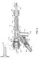
- FIG. 3is an assembled view, in partial cross section, of the components of the manifold and closely associated components and features thereof;
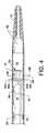
- FIG. 4illustrates the distal portion of the catheter tube and the relationships of radiopaque marker bands, a support ring, a high pressure tube, and a fluid jet emanator to each other and to the catheter tube;
- FIG. 5is an isometric view of the fluid jet emanator shown connected to and in communication with a high pressure tube;
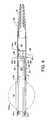
- FIG. 6is a side view, in partial cross section, of the distal portion of the catheter tube in the performance of the method and use thereof which performance utilizes enabling connections and which utilizes functions of the accompanying components in a manner as shown in FIG. 1 ;
- FIG. 8is an illustration similar in many respects to FIG. 4 showing the distal portion of the catheter tube and the relationships of radiopaque marker bands, a support ring, a high pressure tube, a fluid jet emanator, and a balloon to each other and to the catheter tube;
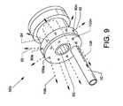
- FIG. 9is an illustration similar in many respects to FIG. 5 and is an isometric view of another fluid jet emanator shown connected to and in communication with a high pressure tube;
- FIG. 11is an isometric exploded and segmented view of a catheter tube and a manifold which are used with enabling components shown in FIG. 1 ;
- FIG. 13is an illustration similar in many respects to FIG. 5 and is an isometric view of another fluid jet emanator shown connected to and in communication with a high pressure tube;
- FIG. 14is similar in many respects to FIG. 6 and is a side view, in partial cross section, of the distal portion of the catheter tube in the performance of the method and use thereof which performance utilizes enabling connections and which utilizes functions of the accompanying components in a manner as shown in FIG. 1 ;
- FIG. 15is an isometric exploded and segmented view of a catheter tube and a manifold which are used with enabling components shown in FIG. 1 ;
- FIG. 16is an illustration similar in many respects to FIG. 4 illustrating the distal portion of the catheter tube and the relationships of radiopaque marker bands, a support ring, a high pressure tube, a fluid jet emanator, and a balloon to each other and to the catheter tube;
- FIG. 17is an illustration similar in many respects to FIG. 13 and is an isometric view of another fluid jet emanator shown connected to and in communication with a high pressure tube;
- FIG. 18is similar in many respects to FIG. 6 and is a side view, in partial cross section, of the distal portion of the catheter tube in the performance of the method and use thereof which performance utilizes enabling connections and which utilizes functions of the accompanying components in a manner as shown in FIG. 1 ;
- FIG. 19is an isometric exploded and segmented view of a catheter tube and a manifold which are used with enabling components shown in FIG. 1 ;
- FIG. 20is an illustration similar in many respects to FIG. 4 illustrating the distal portion of the catheter tube and the relationships of radiopaque marker bands, a support ring, a high pressure tube, and a fluid jet emanator to each other and to the catheter tube;
- FIG. 21is an illustration similar in many respects to FIG. 5 and is an isometric view of another fluid jet emanator shown connected to and in communication with a high pressure tube;
- FIG. 22is similar in many respects to FIG. 6 and is a side view, in partial cross section, of the distal portion of the catheter tube in the performance of the method and use thereof which performance utilizes enabling connections and which utilizes functions of the accompanying components in a manner as shown in FIG. 1 ;
- FIG. 23is an isometric exploded and segmented view of a catheter tube and a manifold which are used with enabling components shown in FIG. 1 ;
- FIG. 24is an illustration similar in many respects to FIG. 4 illustrating the distal portion of the catheter tube and the relationships of radiopaque marker bands, a support ring, a high pressure tube, and a fluid jet emanator to each other and to the catheter tube;
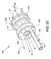
- FIG. 25is an illustration similar in many respects to FIG. 5 and is an isometric view of another fluid jet emanator shown connected to and in communication with a high pressure tube; and,
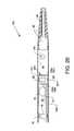
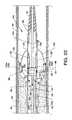
- FIG. 26is similar in many respects to FIG. 6 and is a side view, in partial cross section, of the distal portion of the catheter tube in the performance of the method and use thereof which performance utilizes enabling connections and which utilizes functions of the accompanying components in a manner as shown in FIG. 1 .
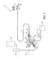
- FIG. 1is a plan view of the visible components of a direct stream hydrodynamic catheter system 10 , which can also be referred to for purposes of brevity as the catheter system 10 .
- the systemincludes a direct stream hydrodynamic catheter tube 12 , also referred to as the catheter tube 12 , in association with a one-piece manifold 14 , the latter having multiple structures extending therefrom or attached thereto including, but not limited to, the flexible multiple feature catheter tube 12 .
- the visible portion of the one-piece manifold 14includes a central tubular body 16 , a threaded exhaust branch 18 , and a high pressure connection branch 20 extending angularly from the central tubular body 16 , a partially shown cavity body 22 extending proximally from the central tubular body 16 and a threaded connection port 24 extending distally from the central tubular body 16 .
- the proximal end of the catheter tube 12is secured to the manifold 14 by the use of a Luer fitting 26 accommodated by the threaded connection port 24 .
- the proximal end of the catheter tube 12extends through a strain relief tube 28 and through the Luer fitting 26 to communicate with the manifold 14 .
- hemostasis nut 30in alignment with and threadingly engaged with the proximal region of the cavity body 22 .
- a threaded high pressure connection port 32is secured to the high pressure connection branch 20 by a Luer connector 34 .
- An introducer 36is shown in FIG. 2 .
- a guidewire 37in association with the disclosure, is shown in FIG. 3 .
- the catheter tube 12extends distally from the manifold 14 and includes an inflow orifice 38 at the distal section of the catheter tube 12 .
- an inflow gapcould be provided in lieu of the inflow orifice 38 .
- a tapered flexible tip 40extends distally from the distal section of the catheter tube 12 and is secured thereto and therein.
- the catheter tube 12functions as an exhaust tube for the evacuation of thrombus or lesion particulate, fluids or other debris or effluent from the thrombus or lesion site.
- the catheter tube 12includes a hydrophilic coating to enhance deliverability along the vasculature or other structure.
- Enabling componentsprovide for the operation and utilization of the catheter tube 12 , the manifold 14 and components closely related thereto and therein include a high pressure fluid source 42 and a high pressure fluid pump 44 connected to the manifold 14 via the threaded high pressure connection port 32 and connector 46 . Also included are an exhaust regulator 47 in the form of a roller pump or other suitable device and a collection chamber 48 connected to the threaded exhaust branch 18 by a connector 49 as shown.
- FIGS. 2 and 3show portions of the disclosure.
- FIG. 2generally is an isometric exploded and segmented view of the catheter tube 12 and the manifold 14 which are used with the enabling components shown in FIG. 1 .
- FIG. 3is an assembled view, in partial cross section, of the components of the manifold 14 and closely associated components and features thereof. Also included is a guidewire 37 incorporated into the use thereof.
- a group of assembled componentsincluding a high pressure tube 50 and a fluid jet emanator 52 , deliver pressurized saline or other suitable fluid to the distal section of the catheter tube 12 for producing fluid jet streams which are directed radially from the fluid jet emanator 52 , as later described in detail.
- the high pressure tube 50preferably of flexible stainless steel or other suitable material, extends within closely associated features or components attached to the manifold 14 and passes therethrough and is aligned with and distal to the strain relief tube 28 .
- the high pressure tube 50extends along a greater portion of and within a lumen 53 of the catheter tube 12 to terminate at the fluid jet emanator 52 .
- the distal end of the high pressure tube 50including the fluid jet emanator 52 , is also shown in greater detail in FIGS. 4 and 5 .
- the manifold 14which is also used with reference to the alternative embodiments, has connected and communicating passageways and cavities ( FIG. 3 ) including a high pressure connection branch passageway 54 , an exhaust branch passageway 56 , a tapered central passageway 58 extending from and through the threaded connection port 24 and through the central tubular body 16 to and communicating with a multiple radius cavity 60 , which preferably is cylindrical and located central to the cavity body 22 .
- External threads 62are located about the proximal portion of the cavity body 22 at the proximal region of the manifold 14 for accommodating the internal threads 64 of the hemostasis nut 30 .
- Beneficial to devices of the disclosureis the use of a flexible self-sealing hemostasis valve 66 and the use of a washer 68 which is located distal to the self-sealing hemostasis valve 66 , the shape and function of which are described in referenced U.S. Pat. No. 7,226,433 which is incorporated herein in its entirety.
- the self-sealing hemostasis valve 66 and the washer 68are aligned within the greater radius portion of the multiple radius cavity 60 of the cavity body 22 .
- the hemostasis nut 30includes a centrally located cylindrical boss 70 .
- the washer 68 and the self-sealing hemostasis valve 66are captured within the greater radius portion of the multiple radius cavity 60 by the threaded engagement of the hemostasis nut 30 to the threads 62 at the proximal end of the manifold 14 .
- the cylindrical boss 70is brought to bear against the collective self-sealing hemostasis valve 66 and the washer 68 bringing pressure to bear, as required, against the self-sealing hemostasis valve 66 which pressure culminates in a forcible sealing of the self-sealing hemostasis valve 66 about the guidewire 37 .
- a ferrule 72which is aligned within a passageway 74 of the threaded high pressure connection port 32 , the combination of which is partially aligned within an interior passageway 76 of the Luer connector 34 .
- the proximal end of the flexible high pressure tube 50shown in segmented form in FIG. 2 , is used for the delivery of nominal or high pressure ablation liquids or for the delivery of drugs or other liquids and is suitably secured in a central passageway of the ferrule 72 to communicate with the interior passageway 74 of the threaded high pressure connection port 32 , as shown in FIG. 3 .
- the proximal end of the high pressure tube 50also extends through the high pressure connection branch passageway 54 , through part of the tapered central passageway 58 , through the strain relief tube 28 and Luer fitting 26 , and through the lumen 53 of the catheter tube 12 .
- the high pressure tube 50extends through a support ring 78 and is suitably attached thereto to provide an anchoring and alignment structure for the high pressure tube 50 thereby affixing the distal portion of the high pressure tube 50 within the distal end of the catheter tube 12 .
- the high pressure tube 50also extends indirectly through the radiopaque marker band 80 .
- the concentrically aligned radiopaque marker band 80 and the support ring 78are shown forcibly contacting the full wall thickness of the catheter tube 12 at the distal end of the catheter tube 12 .
- the high pressure tube 50is preferably attached to the support ring 78 , such as by welding or other suitable means, where the support ring 78 functions as a support for the catheter tube 12 in the region beneath the radiopaque marker band 80 .
- the high pressure tube 50extends across the inflow orifice 38 and terminates within an internal annular manifold (not shown) of the fluid jet emanator 52 and is suitably attached thereto where the interior cavity (not shown) of the fluid jet emanator 52 communicates with the lumen of the high pressure tube 50 , such as in the closely related fluid jet emanator described in the previously referenced U.S. Pat. No. 7,879,022 or other applications or patents assigned to the assignee.
- the fluid jet emanator 52also shown in FIG.
- annular groove 84which is in coordinated use with a radiopaque marker band 82 to secure the fluid jet emanator 52 within the distal section of the catheter tube 12 .
- the distally located radiopaque marker band 82is forcibly applied around the distal end of the catheter tube 12 to cause a frictional annular engagement with all or part of the annular groove 84 of the fluid jet emanator 52 .
- Such frictional engagementis sufficient to place the outer radial surface of the radiopaque marker band 82 (also 80 ) in a position lesser than the general and greater outer radial surface of the catheter tube 12 , thereby providing, in part, a catheter tube 12 having no elements protruding beyond the general outer radial surface thereof for an unimpeded and smooth distal or proximal transition of the catheter tube 12 within a vein, artery or the like.
- a passageway 86( FIG. 5 ) is shown central to the fluid jet emanator 52 to accommodate the passage of a guidewire 37 (shown in FIG. 3 ).
- the tapered flexible tip 40is shown suitably secured to the distal end of the distal section of the catheter tube 12 .
- the tapered flexible tip 40includes a multiple radius inner passageway 88 for the accommodation of a guidewire 37 .
- the radiopaque marker band 80is shown displaced a short distance distal to the support ring 78 and the fluid jet emanator 52 is shown displaced proximally a short distance from the radiopaque marker band 82 for the purpose of clarity, but are shown in frictional engagement in their actual positions along and with respect to the distal end of the catheter tube 12 in FIG. 4 .
- the relationships of the radiopaque marker bands 80 and 82 , the support ring 78 , and the fluid jet emanator 52 , respectively, to each other and to the catheter tube 12are shown best in FIG. 4 .
- the tapered flexible tip 40as opposed to a rounded and nontapered flexible tip, can part and more easily penetrate deposits of thrombus or lesions during its insertional travel in a distal direction instead of advancing or pushing such deposits of thrombus or lesions distally.
- the decreasing diameter in a distal direction of the tapered flexible tip 40also allows for an increased flexibility in negotiating and passing through tortuous paths.
- the exhaust tube support ring 78 in use with the radiopaque marker band 80 and the use of the fluid jet emanator 52 with the marker band 82 within and about the proximal and distal sections of the catheter tube 12 , respectively,are examples of structures offering support or reinforcement along the catheter tube 12 .
- Such a support ring 78 , marker bands 80 and 82 , and the external structure of the fluid jet emanator 52provide for the use of a thinner wall thickness for the catheter tube 12 and allow for a larger and more effective and efficiently sized lumen 53 of the catheter tube 12 , as well as contributing to a reduced sized outer diameter.
- Such support rings and external structure of the fluid jet emanator 52also contribute to supportively maintain the diameter and overall shape of the catheter tube 12 when the catheter tube 12 is pushed or advanced along a vein or artery, as well as aiding in torsional support.
- FIG. 5is an isometric view of the fluid jet emanator 52 shown connected to and in communication with the high pressure tube 50 .
- the fluid jet emanator 52includes a plurality of like and nominal sized radially directed jet orifices 90 a - 90 n located around the periphery of the fluid jet emanator as well as including the previously described annular groove 84 and passageway 86 .
- the plurality of radially directed jet orifices 90 a - 90 nare in common and are pressurized in common by pressured saline provided through the high pressure tube 50 .
- the high pressure tube 50delivers high pressure saline or other suitable fluid to the fluid jet emanator 52 for producing and distributing high pressure and nominally sized radially directed fluid jet streams 92 of saline or other suitable fluids which emanate from the radially directed jet orifices 90 a - 90 n of the fluid jet emanator 52 to perform functions, as described herein.
- a plurality of holes 94 a - 94 n corresponding to and in alignment with the radially directed jet orifices 90 a - 90 nare provided in the distal end of the catheter tube 12 , as shown in FIG. 4 , or in alternative embodiments in order to allow the passage of the radially directed fluid jet streams 92 therethrough.
- fluid jet emanator 52Although the use of the particular style of fluid jet emanator 52 is shown, other fluid jet emanators having other configurations emanating radially directed fluid jet streams 92 can also be used in lieu of the fluid jet emanator 52 shown in FIG. 5 and the use of other fluid jet emanators shall not be considered to be limiting to the scope of the disclosure.
- a normal guidewireis deployed in a blood vessel 96 requiring treatment or, in the alternative, a filter guidewire or balloon occlusion guidewire could also be used.
- the catheter tube 12 and other closely associated and aligned components directly associated therewithconsisting mainly of the high pressure tube 50 and the fluid jet emanator 52 are advanced over and along a guidewire ( 37 ) which is aligned within the blood vessel 96 for the purpose of debris/thrombus/lesion removal, drug infusion, or other procedures and maneuvered into an appropriate position for treatment.
- a generic guide catheter or sheathcan be incorporated as necessary to offer assistance in placing the catheter tube 12 and closely aligned components in direct association therewith of the direct stream hydrodynamic catheter system 10 within the desired location of the blood vessel 96 in order that the tapered tip 40 of the catheter tube 12 can be extended through the thrombus or lesions 98 to position the fluid jet emanator in very close proximity to the thrombus or lesions 98 .
- the catheter tube 12may be moved proximally or distally during the procedure to maximize the effect of the catheter system. Further interventions can be executed as normal over the remaining guidewire or guidewire device.
- FIG. 6is a side view, in partial cross section, of the catheter tube 12 in the performance of the method and use thereof which utilizes enabling connections and which utilizes functions of the accompanying components in a manner as shown in FIG. 1 with particular attention given to the distal section of the catheter tube 12 , the flexible tapered tip 40 , the fluid jet emanator 52 , the inflow orifice 38 , and other closely associated components positioned in the blood vessel 96 containing deposits of thrombus or lesions 98 . More specifically and with reference to FIGS. 1 and 6 , the mode of operation is further described in use.
- the direct stream hydrodynamic catheter tube 12is engaged over and about a guidewire 37 wherein the guidewire 37 (previously inserted into a vein or artery) can first slideably pass through the passageway 88 of the tapered flexible tip 40 , into and through the lumen 53 of the catheter tube 12 , followed by transiting the passageway 86 of the fluid jet emanator 52 , past the inflow orifice 38 , followed by transiting the lumen 53 of the catheter tube 12 , the strain relief tube 28 , the tapered central passageway 58 of the manifold 14 ( FIG. 3 ) and slideably within and in sealed engagement with the hemostasis valve 66 ( FIG. 3 ) to finally exit from the hemostasis nut 30 .
- the distal portion of the high pressure tube 50delivers pressurized saline or other suitable fluid to the fluid jet emanator 52 to produce and distribute, preferably, non-hemolyzing radially directed fluid jet streams 92 of saline or other suitable fluids which emanate as direct fluid jet streams from the radially directed jet orifices 90 a - 90 n of the fluid jet emanator 52 in order to accomplish thrombectomy functions, as described herein.
- Carefully generated operating pressure and fluid flows at values short of hemolysiscan be provided primarily by controlling the input fluid pressure at the high pressure fluid pump 44 and/or by controlling the exhaust rate at the exhaust regulator 47 , whereby the exhaust regulator 47 is operated to provide a negative pressure for effluent aspiration.
- Other fluid jet emanators of appropriate size and/or configurationcan also be incorporated in lieu of the fluid jet emanator 52 within the distal section of the catheter tube 12 to emanate or emit one or more radially directed fluid jet streams 92 .
- the use of the radially directed fluid jet streams 92 from the radially directed jet orifices 90 a - 90 nprovides for the fluid jet impingement of the deposits of thrombus or lesions of 98 on the inner wall of the blood vessel 96 adjacent to or in close proximity to the radially directed jet orifices 90 a - 90 n in order to impinge, ablate and loosen deposits of thrombus or lesions 98 , whereby such thrombus or lesion particulate and fluids can be entrained through one or more inflow orifices 38 by aspiration involving the use of an exhaust regulator 47 to be exhausted proximally through the catheter tube 12 .
- drugs for treatment or for lysing of the thrombus or lesions 98can also be delivered via the radially directed jet orifices 90 a - 90 n and radially directed fluid jet streams 92 in order to soften the deposits of thrombus or lesions 98 in the region of the blood vessel 96 adjacent to or in close proximity to the radial jet orifices 90 a - 90 n , thereby benefiting and making use of the radially directed fluid jet streams 92 more effective.
- the drugsare delivered through the high pressure tube 50 to the sites of the deposits of thrombus or lesions 98 using the fluid jet emanator 52 .
- One or more inflow orifices 38receive, ingest and entrain thrombus or lesions 98 in the form of particulate and/or debris therethrough by fluidic flow and are entrained to be urged and carried along the lumen 53 of the catheter tube 12 by aspiration involving the exhaust regulator 47 , wherein the entrainment of thrombus or lesions 98 particulate and/or debris through the inflow orifice(s) 38 is influenced by and based on entrainment in association with aspiration in coordination with the exhaust regulator 47 through the catheter 12 .
- the inflow orifice 38is sufficiently sized for aspiration or multiple inflow orifices may be used in order to achieve a desired fluid inflow and aspiration.
- the outflow of fluid and thrombus or lesionsis driven proximally through the catheter tube 12 by an internal pressure which results from the radially directed fluid jet streams 92 and the fluid entrained through the inflow orifice 38 and is assisted by aspiration by use of the exhaust regulator 47 .
- the radially directed fluid jet streams 92are driven by the same pressure source where the velocity is controllingly influenced by the high pressure pump 44 and the total area of all of the radially directed jet orifices 90 a - 90 n .
- the velocity and strength of the radially directed jet streams 92can be influenced and controlled.
- nominally sized radially directed jet orifices 90 a - 90 nprovides for fluid jet streams having enough momentum which can be delivered by a large non-hemolysing fluid jet streams ( 92 ) which are equivalent in energy, via an increased flow rate, to a high velocity, smaller, fluid jet stream to be described later.
- the principle for an aggressive debris removalis dependent on the velocity of the radially directed jet streams 92 . Consider that there is some critical velocity for debris liberation. As the radially directed jet streams 92 travel through a fluid environment, the jet streams will entrain surrounding fluid whereby the velocity of the fluid jet streams will slow. There are empirical relationships for turbulent jet streams that show that velocity is proportional to the diameter of the jet streams and to the initial velocity of the jet streams.
- the velocity at a given distancewould be increased by either increasing the initial jet stream velocity or increasing the jet orifice diameter.
- the pump rate of the high pressure pump 44would need to be increased in order to maintain the fluid jet stream velocity.
- the catheter systemis designed with a given set of jet orifice diameters and the high pressure pump 44 pump rate is adjusted to achieve the proper efficacy.
- radially directed jet orificesin a size range from 0.001 inch to 0.040 inch for emanation of saline or other suitable fluid therefrom at a velocity range of 1 to 250 m/s.
- Proximally directed jet orificescan range in size from 0.001 inch to 0.040 inch for emanation of saline or other suitable fluid therefrom in a velocity range of 1 to 250 m/s.
- Distally directed jet orifices where usedcan range in size from 0.001 inch to 0.040 inch for emanation of saline or other suitable fluid therefrom in a velocity range of 1 to 250 m/s.
- the velocity and strength of the radially directed jet streamcan be controlled.
- the radially directed jet orificescan be sized such that the velocity of the jet streams is decreased to a point where no red blood cells are hemolysed, but the momentum of the jet streams can then be increased by means of an infused volume such that the efficacy of the catheter system is as high as that of the high velocity thrombectomy catheters disclosed in Applicant's related references as set forth above.
- the general operating pressure of the catheter systemcan range from 50 psi to 20,000 psi.
- those catheter systems of the embodiments disclosed hereinuse nominal sized radially directed jet orifices 90 a - 90 n to emanate radially directed fluid jet streams 92
- the fourth alternative embodimentutilizes cross stream jets 132 ( FIG. 22 ) where the occurrence of hemolysis is not desired or is to be minimized.
- Other embodimentscan use smaller sized radially directed jet orifices 112 a - 112 n (shown later) to emanate radially directed fluid jet streams 92 of greater strength and efficacy.
- FIG. 7a first alternative embodiment, is an illustration similar in many respects to FIG. 2 showing a direct stream hydrodynamic catheter tube 12 a , also referred to as the catheter tube 12 a , and the manifold 14 and components associated therewith and wherein each is connected to and utilizes functions of the accompanying enabling components in a manner similar to that shown in FIG. 1 where all numerals correspond to those elements previously described or as otherwise described herein.
- the catheter tube 12is reconfigured as a catheter tube 12 a to additionally include a balloon 100 , which is self-inflating, located at the distal end thereof and at a position proximal to the inflow orifice 38 .
- a support ring 102is additionally included and is secured to the high pressure tube 50 .
- a marker band 104is also additionally included and is coaxially and indirectly aligned with the support ring 102 , as later described in detail.
- the components of FIG. 7are used with the enabling components referred to and shown in FIG. 1 where such enabling components consist of the high pressure fluid source 42 , the high pressure fluid pump 44 , the threaded high pressure connection port 32 and connector 46 , the exhaust regulator 47 , the collection chamber 48 and the connector 49 which are used much in the same manner as previously described.
- the referenced enabling components in combination with the catheter tube 12 a and the manifold 14 and closely associated components thereofcomprise a direct stream hydrodynamic catheter system 10 a which is also referred to as the catheter system 10 a .
- catheter tube 12 aAlthough the catheter tube 12 a , the manifold 14 , and closely associated components of each are shown referenced to the catheter system 10 a in FIG. 7 , it is understood that the previously referenced enabling components referred to and shown in FIG. 1 , but not shown in FIG. 7 , are also part of the catheter system 10 a.
- the high pressure tube 50also extends through the support ring 102 and is suitably connected thereto to provide for an additional anchoring and alignment structure for the high pressure tube 50 in order to affix the distal portion of the high pressure tube 50 within the distal end of the catheter tube 12 a .
- the high pressure tube 50also extends indirectly through the radiopaque marker band 104 .
- the concentrically aligned radiopaque marker band 104 and the support ring 102are shown forcibly contacting the full wall thickness of the catheter tube 12 a proximal to the balloon 100 .
- the high pressure tube 50preferably is attached to the support ring 78 , such as by welding or other suitable means, where the support ring 78 functions as a support for the catheter tube 12 a in the region beneath the radiopaque marker band 80 .
- the high pressure tube 50extends across the inflow orifice 38 and terminates within an internal annular manifold (not shown) of the fluid jet emanator 52 a and is suitably attached thereto where the fluid jet emanator 52 a communicates with the lumen of the high pressure tube 50 .
- the balloon 100which is continuous with the catheter tube 12 a , preferably has a wall thickness less than that of the general wall thickness of the catheter tube 12 a , is aligned in a longitudinal orientation between the coaxially aligned marker band 104 and support ring 102 and the aligned marker band 80 and support ring 78 .
- the profile of the balloon 100 in the inflated modeis shown in dashed lines and referenced as the inflated balloon 100 a.
- FIG. 9is an illustration similar in many respects to FIG. 5 showing an isometric view of an alternative fluid jet emanator 52 a connected to and in communication with the high pressure tube 50 .
- the fluid jet emanator 52 aalso includes a plurality of proximally (rearwardly) directed orifices 106 a - 106 n located on and about a proximal face of the emanator 52 a and in parallel alignment to the longitudinal axis of the fluid jet emanator 52 a , as well as including the previously described annular groove 84 and passageway 86 .
- the plurality of radially directed jet orifices 90 a - 90 n and the plurality of proximally directed jet orifices 106 a - 106 nare in common and are pressurized in common by pressured saline provided through the high pressure tube 50 .
- the high pressure tube 50delivers a pressurized saline or other suitable fluid to the fluid jet emanator 52 a for producing and distributing nominal sized radially directed fluid jet streams 92 of saline or other suitable fluids which emanate from the radially directed jet orifices 90 a - 90 n of the fluid jet emanator 52 a to perform functions, as described herein.
- the fluid jet emanator 52 aalso provides and distributes pressurized proximally directed fluid jet streams 108 of saline or other suitable fluids which are directed proximally from the proximally directed orifices 106 a - 106 n to perform functions, as described herein.
- a normal guidewire 37is deployed in a blood vessel 96 requiring treatment, or in the alternative, a filter guidewire or balloon occlusion guidewire could also be used.
- the catheter tube 12 a and other closely associated and aligned components directly associated therewithconsisting mainly of the high pressure tube 50 , the fluid jet emanator 52 a , the distal section of the catheter tube 12 a , and the uninflated balloon 100 are advanced over and along the guidewire 37 and aligned within the blood vessel 96 for the purpose of debris/thrombus/lesion maceration and removal, drug infusion, or other procedures and maneuvered into an appropriate position within the blood vessel 96 for treatment.
- a generic guide catheter or sheathcan be incorporated as necessary to offer assistance in placing the catheter tube 12 a and closely aligned components in direct association therewith of the direct stream hydrodynamic catheter system 10 a within the desired location of the blood vessel 96 in order that the tapered flexible tip 40 of the catheter tube 12 a can be extended through and beyond the thrombus or lesions 98 to position the fluid jet emanator 52 a in very close proximity to the thrombus or lesions 98 and to place the self-inflating balloon 100 proximal to the thrombus or lesions 98 .
- the direct stream thrombectomy catheter system 10 ais then activated, wherein the balloon 100 is automatically and expandingly deployed reforming as an expanded balloon 100 a , and then thrombus, debris and the like are removed or drugs can be infused by a desired procedure.
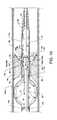
- FIG. 10is a side view, in partial cross section, of the catheter tube 12 a of the first alternative embodiment illustrating the performance of the method and use thereof which performance utilizes enabling connections and which performance utilizes functions of the accompanying components in a manner similar to that shown in FIG. 1 with particular attention given to the distal section of the catheter tube 12 a , the flexible tapered tip 40 , the inflated self-inflated balloon 100 a , the fluid jet emanator 52 a , the inflow orifice(s) 38 (reoriented), and other closely associated components positioned in the blood vessel 96 containing deposits of thrombus or lesions 98 .
- the direct stream hydrodynamic catheter tube 12 acan be engaged over and about the guidewire 37 , wherein the guidewire 37 (previously inserted into a vein or artery) can first slideably pass through the passageway 88 of the tapered flexible tip 40 , into and through the lumen 53 of the catheter tube 12 a , followed by transiting the passageway 86 of the fluid jet emanator 52 a , past the inflow orifice(s) 38 , through the balloon 100 , followed by additional transiting through the lumen 53 of the catheter tube 12 a , through the strain relief tube 28 , the tapered central passageway 58 ( FIG. 3 ), slideably within and in sealed engagement with the hemostasis valve 66 ( FIG. 3 ) to finally exit from the hemostasis nut 30 .
- the distal portion of the high pressure tube 50delivers pressured saline or other suitable fluid to the fluid jet emanator 52 a to produce and distribute non-hemolyzing radially directed fluid jet streams 92 of saline or other suitable fluids which emanate as direct stream from the radially directed jet orifices 90 a - 90 n of the fluid jet emanator 52 a to accomplish thrombectomy functions in a manner as previously described.
- Carefully generated operating pressure and fluid flows at values short of hemolysiscan be accomplished primarily by controlling the input fluid pressure at the high pressure fluid pump 44 and/or by controlling the exhaust rate at the exhaust regulator 47 , whereby the exhaust regulator 47 is operated to provide a negative pressure for effecting effluent aspiration.
- the pressured saline, or other suitable fluidis also delivered by the high pressure tube 50 to the fluid jet emanator 52 a to produce and distribute proximally directed fluid jet streams 108 of saline or other suitable fluids which are directed proximally from the proximally directed jet orifices 106 a - 106 n ( FIG. 9 ) of the fluid jet emanator 52 a , and to thence transit parallel to the inflow orifice(s) 38 , and finally into the distal section of the catheter tube 12 a to flow proximally therethrough and provide for the inflation of the balloon 100 and to complement the aspiration of effluent flow.
- the balloon 100is automatically and expandingly deployed to reform as an inflated balloon 100 a by the pressure exerted from the proximally directed high velocity fluid jet streams 108 emanating from the proximally directed jet orifices 106 a - 106 n of the fluid jet emanator 52 a and complemented by the pressurized effluent flow through the lumen 53 of the catheter tube 12 a .
- the pressurized inflation of the inflated balloon 100 a or maintaining a state of inflation of the inflated balloon 100 ais also assisted by utilizing back pressure along the length of the catheter tube 12 a .
- An operational advantage of the present catheter systemis the utilization of an exhaust outflow and an internal pressure which are produced by the proximally directed fluid jet stream(s) 108 in combination with a restrictive control of the outflow, such as influenced by the exhaust regulator 47 in assisting an automatic expansion of the balloon 100 which forcibly impinges upon and seals against the inner walls of the blood vessel 96 .
- the reduced thickness of the material comprising the balloon 100allows the balloon 100 to expand sufficiently to reform as the inflated balloon 100 a , the further expansion of which is restricted by its impingement on the wall of the blood vessel 96 .
- the operating pressure and fluid flows affecting the inflation of the balloon 100can be affected primarily by controlling the input fluid pressure at the high pressure fluid pump 44 and/or by controlling the exhaust rate at the exhaust regulator 47 whereby the exhaust regulator 47 is operated to provide a negative pressure for effecting effluent aspiration.
- Other fluid jet emanators of appropriate size and/or configurationcan also be incorporated in lieu of the fluid jet emanator 52 a positioned within the distal section of the catheter tube 12 a in order to emanate or emit one or more radially directed fluid jet streams 92 and to emanate or emit one or more proximally directed fluid jet streams 108 proximally along or near the longitudinal axis of the catheter tube 12 a ; the preceding alternatives shall not be considered to be limiting to the scope of the disclosure.
- the inflated balloon 100 aBy inflating the balloon 100 , the peripheral circumference of the inflated balloon 100 a impinges upon the wall of the blood vessel 96 in order to effect a fluid flow reduction or cessation within the blood vessel 96 .
- the inflated balloon 100 ai.e., the balloon 100 , can be compliant, semi-compliant, or noncompliant according to the procedure performed.
- the inflated balloon 100 aprovides for the uniform centering and positioning of the distal section of the catheter tube 12 a within the blood vessel 96 , thereby providing a substantially equal annular spacing between the wall of the blood vessel 96 and the inflow orifice 38 for uniform access and clearance thereto and thereabout.
- the inflated balloon 100 aalso provides for an annular spacing between the blood vessel 96 and the inflow orifice(s) 38 in order to provide for the access and clearance to and about the inflow orifice 38 .
- the use of the radially directed fluid jet streams 92 from the radially directed jet orifices 90 a - 90 nprovides for the fluid jet impingement of the deposits of lesions or thrombus 98 on the inner wall of the blood vessel 96 adjacent to or in close proximity to the radially directed jet orifices 90 a - 90 n in order to impinge, ablate and loosen deposits of lesions or thrombus 98 , whereby such thrombus or lesion particulate and fluids can be entrained through one or more inflow orifices 38 by aspiration involving the use of the exhaust regulator 47 , as previously described.
- the action and high velocity of the proximally directed fluid jet streams 108 of saline or other suitable fluids proximally through the catheter tube 12 ain addition to causing the inflation of balloon 100 , provide a force for driving thrombus or lesions 98 and fluid flow proximally through the lumen 53 of the catheter tube 12 a .
- drugs for treatment or for lysing of the thrombus deposits or lesions 98can also be delivered via the high pressure tube 50 and the fluid jet emanator 52 a and the radially directed jet orifices 90 a - 90 n and radially directed fluid jet streams 92 in order to soften the deposits of lesions or thrombus 98 in the region of the blood vessel 96 adjacent to or in close proximity to the radial jet orifices 90 a - 90 n , thereby benefiting and making use of the radially directed fluid jet streams 92 more effective.
- the proximally directed fluid jet streams 108impinge upon, provide drag forces on, and break up or macerate such entrained thrombus or lesions 98 particulate and/or debris which have been ingested and entrained through the inflow orifice(s) 38 .
- Such debrisis further entrained, urged and carried proximally along the lumen 53 of the catheter tube 12 a by internal pressure and by aspiration involving the exhaust regulator 47 , as well as by the additional force provided by the action of the proximally directed fluid jet streams 108 .
- the entrainment of thrombus or lesions 98 particulate and/or debris through the inflow orifice(s) 38is influenced by and based on coordinated association primarily involving the operation of the exhaust regulator 47 and the operation of the high pressure fluid pump 44 through the catheter 12 a .
- the inflow orifice 38is sufficiently sized for aspiration or multiple inflow orifices may be used in order to achieve a desired fluid inflow and aspiration.
- the catheter tube 12 amay be moved proximally or distally during the procedure to maximize the effect of the catheter system.
- the balloon 100can be alternately pressurized and depressurized, whereby thrombus or lesions 98 can be compacted in order to enlarge a passage.
- the inflated balloon 100 ais generally deflated sufficiently under normal arterial pressure to be removed safely, or deflation can be aided with a manual syringe attached to the manifold, or deflation can be aided by means of the exhaust regulator 47 . Further interventions can be executed as normal over the remaining guidewire or guidewire device. Cessation of fluid flow in a blood vessel or other conduit maximizes the effect of the catheter system 10 a in terms of debris or tissue removal.
- Use of devices of the present disclosurecan also provide for the performance of a modified embolectomy by breaking up clots as the inflated balloon 100 a is moved through a blocked vessel or can be used to minimize any distal or proximal embolization.
- the radially directed fluid jet streams 92are driven by the same pressure source as the proximally directed fluid jet streams 108 .
- the velocity of the fluid directed jet streamsis controlled by the high pressure pump 44 , the total area of all of the radially directed jet orifices 90 a - 90 n and the proximally directed jet orifices 106 a - 106 n .
- Debris removalis influenced by and accomplished by aspiration in coordination with the operation of the high pressure fluid pump 44 and the exhaust regulator 47 through the catheter tube 12 a .
- the inflow orifice 38is sufficiently sized for aspiration.
- the velocity and strength of the radially directed fluid jet streams 92 and the proximally directed fluid jet streams 108can be influenced and controlled.
- the use of nominally sized radially directed jet orifices 90 a - 90 nprovides for the use of fluid jet streams having enough momentum that can be delivered by large non-hemolysing fluid jet streams ( 92 ) which are equivalent in energy, via increased flow rate, to high velocity smaller fluid jet streams described later.
- the principle for an aggressive debris removalis based on the velocity of the radially directed jet streams 92 .
- FIG. 11a second alternative embodiment is shown as an illustration similar in many respects to FIG. 2 showing a direct stream hydrodynamic catheter tube 12 b , also referred to as the catheter tube 12 b , and a manifold 14 and components associated therewith and wherein each is connected to and utilizes functions of the accompanying enabling components in a manner similar to that shown in FIG. 1 where all numerals correspond to those elements previously described or as otherwise described herein.
- the components of FIG. 11are used with the enabling components referred to and shown in FIG.
- the referenced enabling components in combination with the catheter tube 12 b and the manifold 14 and closely associated components thereofcomprise a direct stream hydrodynamic catheter system 10 b which is also referred to as the catheter system 10 b .
- the catheter system 10 b of this embodimentprovides for an increased fluid velocity with smaller sized radially projected fluid jet streams therefrom by using smaller radially directed jet orifices, as well as including the provision of and the use of the previously described proximally directed fluid jet streams 108 .
- catheter tube 12 bAlthough the catheter tube 12 b , the manifold 14 , and closely associated components of each are shown referenced to the catheter system 10 b in FIG. 11 , it is understood that the previously referenced enabling components referred to and shown in FIG. 1 , but not shown in FIG. 11 , are also a significant part of the catheter system 10 b.
- FIG. 12is an illustration similar in many respects to FIG. 4 showing the distal end of the catheter tube 12 b used in lieu of the catheter tube 12 and shown in use with a fluid jet emanator 52 b in lieu of the fluid jet emanator 52 , wherein the fluid jet emanator 52 b includes additional structure, features and functionality such as described in FIG. 13 .
- FIG. 13is an illustration similar in many respects to FIG. 9 showing an isometric view of the alternative fluid jet emanator 52 b connected to and in communication with the high pressure tube 50 alternatively including the plurality of small sized radially directed jet orifices 112 a - 112 n in lieu of the nominally sized radially directed jet orifices 90 a - 90 n of the previous embodiments.
- the fluid jet emanator 52 balso includes the previously shown and described plurality of proximally (rearwardly) directed orifices 106 a - 106 n located on and about a proximal face of the fluid jet emanator 52 b in parallel alignment with the longitudinal axis of the fluid jet emanator 52 b , as well as including the previously described annular groove 84 and passageway 86 .
- the plurality of radially directed jet orifices 112 a - 112 n and the plurality of proximally directed orifices 106 a - 106 nare in common and are pressurized in common by the pressurized saline provided through the high pressure tube 50 .
- the high pressure tube 50delivers pressurized saline or other suitable fluid to the fluid jet emanator 52 b for producing and distributing small sized radially directed fluid jet streams 114 at a high pressure which jet streams emanate from the radially directed jet orifices 112 a - 112 n of the fluid jet emanator 52 b to vigorously and more powerfully perform functions, as described herein.
- the fluid jet emanator 52 balso produces and distributes pressurized proximally directed fluid jet streams 108 of saline or other suitable fluids which fluid jet streams are directed proximally from the proximally directed orifices 106 a - 106 n to perform functions, as described herein.
- a normal guidewireis deployed in a blood vessel 96 requiring treatment, or in the alternative, a filter guidewire or balloon occlusion guidewire could also be used.
- the catheter tube 12 b and other closely associated and aligned components directly associated therewithconsisting mainly of the high pressure tube 50 and the fluid jet emanator 52 are advanced over and along a guidewire ( 37 ) which is aligned within the blood vessel 96 for the purpose of debris/thrombus/lesion removal, drug infusion, or other procedures, and maneuvered into an appropriate position for treatment.
- a generic guide catheter or sheathcan be incorporated as necessary to offer assistance in placing the catheter tube 12 b and closely aligned components, in direct association therewith, of the direct stream hydrodynamic catheter system 10 b within the desired location of the blood vessel 96 in order that the tapered tip 40 of the catheter tube 12 b can be extended through and beyond the thrombus or lesions 98 and in order to position the fluid jet emanator in very close proximity to the thrombus or lesions 98 .
- the direct stream thrombectomy catheter 10 bis then activated wherein thrombus, debris, lesions and the like can be infused by a desired procedure.
- the catheter tube 12 bmay be moved proximally or distally during the procedure to maximize the effect of the system. Further interventions can be executed as normal over the remaining guidewire or guidewire device.
- FIG. 14is a side view, in partial cross section, of the catheter tube 12 b of the second alternative embodiment illustrating the performance of the method and use thereof which utilizes enabling connections and which performance utilizes functions of the accompanying components in a manner similar to that shown in FIG. 1 with particular attention given to the distal section of the catheter tube 12 b , the flexible tapered tip 40 , the fluid jet emanator 52 b , the inflow orifice(s) 38 (reoriented), and other closely associated components positioned in the blood vessel 96 containing deposits of thrombus or lesions 98 . More specifically and with reference to FIGS. 1 and 14 , the mode of operation is further described in use whereby the direct stream hydrodynamic catheter tube 12 b is engaged over and about the guidewire 37 in a manner as previously described.
- the distal portion of the high pressure tube 50delivers pressurized saline or other suitable fluid to the fluid jet emanator 52 b to produce and distribute small sized, high powered, radially directed fluid jet streams 114 of saline or other suitable fluids which emanate as direct stream from the radially directed jet orifices 112 a - 112 n of the fluid jet emanator 52 b to accomplish thrombectomy functions, as previously described.
- Carefully generated operating pressure and fluid flowscan be influenced primarily by controlling the input pressure fluid at the high pressure fluid pump 44 and/or by controlling the exhaust rate at the exhaust regulator 47 , whereby the exhaust regulator 47 is operated to provide a negative pressure for effluent aspiration.
- Other fluid jet emanators of appropriate size and/or configurationcan be incorporated in lieu of the fluid jet emanator 52 b within the distal section of the catheter tube 12 b in order to emanate or emit one or more radially directed fluid jet streams 114 .
- the use of the high powered radially directed fluid jet streams 114 from the radially directed jet orifices 112 a - 112 nprovides for the fluid jet impingement of the deposits of thrombus or lesions 98 on the inner wall of the blood vessel 96 adjacent to or in close proximity to the radially directed jet orifices 112 a - 112 n in order to impinge, ablate and loosen deposits of thrombus or lesions 98 , whereby such thrombus or lesion particulate and fluids can be entrained by the fluid inflow, as shown by the directed arrow 128 in FIG.
- drugs for treatment or for lysing of the thrombus or lesions 98can also be delivered via the radially directed jet orifices 112 a - 112 n and radially directed fluid jet streams 114 in order to soften the deposits of thrombus or lesions 98 in the region of the blood vessel 96 adjacent to or in close proximity to the radial jet orifices 112 a - 112 n , thereby making use of the radially directed fluid jet streams 114 more effective.
- the drugsare delivered through the high pressure tube 50 to the sites of the deposits of thrombus or lesions 98 using the fluid jet emanator 52 b.
- One or more inflow orifices 38receive, ingest and entrain thrombus or lesions 98 in the form of particulate and/or debris therethrough by fluidic flow and are entrained to be urged and carried along the lumen 53 of the catheter tube 12 b by aspiration involving the exhaust regulator 47 , whereby the entrainment of thrombus or lesions 98 particulate and/or debris through the inflow orifice(s) 38 is influenced by and based on entrainment in association with aspiration in coordination with the exhaust regulator 47 through the catheter 12 b .
- the inflow orifice 38is sufficiently sized for aspiration or multiple inflow orifices may be used in order to achieve a desired fluid inflow and aspiration.
- the outflow of fluid and thrombus or lesionsis driven proximally through the catheter tube 12 b by an internal pressure which results from the radially directed fluid jet streams 92 and the fluid entrained through the inflow orifice 38 and is assisted by aspiration by the use of the exhaust regulator 47 .
- the radially directed fluid jet streams 114are driven by the same pressure source where the velocity is controllingly influenced by the high pressure pump 44 and the total area of all of the radially directed jet orifices 112 a - 112 n .
- the velocity and strength of the radially directed fluid jet streams 114can be influenced and controlled.
- the principle for an aggressive debris removalis dependent on the velocity of the radially directed fluid jet streams 114 . Consider that there is some critical velocity for debris liberation.
- the fluid jet streams 114will entrain surrounding fluid whereby the velocity of the fluid jet streams will slow.
- turbulent fluid jet streamsThere are empirical relationships for turbulent fluid jet streams that show that velocity is proportional to the diameter of the fluid jet streams and to the initial velocity of the fluid jet streams.
- the velocity at a given distancecould be increased by either increasing the initial fluid jet stream velocity or increasing the jet orifice diameter.
- the pump flow ratemust be adjusted depending on the size of the jet orifice diameter and the desired jet stream velocity.
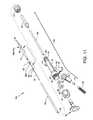
- FIG. 15a third alternative embodiment, is an illustration similar in many respects to FIG. 2 showing a direct stream hydrodynamic catheter tube 12 c , also referred to as the catheter tube 12 c , and the manifold 14 and components associated therewith and wherein each is connected to and utilizes functions of the accompanying enabling components in a manner similar to that shown in FIG. 1 where all numerals correspond to those elements previously described or as otherwise described herein.
- the catheter tube 12is reconfigured as a catheter tube 12 c to additionally include one or more balloon inflation inflow orifices 116 located distal to a fluid jet emanator 52 c , as best shown in FIG.
- FIG. 15The components of FIG. 15 are used with the enabling components referred to and shown in FIG. 1 where such enabling components consist of the high pressure fluid source 42 , the high pressure fluid pump 44 , the threaded high pressure connection port 32 and connector 46 , the exhaust regulator 47 , the collection chamber 48 , and the connector 49 which are used much in the same manner as previously described.
- the referenced enabling components in combination with the catheter tube 12 c and the manifold 14 and closely associated components thereofcomprise a direct stream hydrodynamic catheter system 10 c which is also referred to as the catheter system 10 c , wherein the catheter system 10 c provides for an increased velocity but smaller sized radially projected fluid jet streams therefrom by using small sized radially directed jet orifices.
- the catheter system 10 cincludes the provision of and the use of the previously described pressurized proximally directed fluid jet streams 108 and the previously described pressurized radially directed fluid jet streams 114 . Additionally, the catheter system 10 c includes the provision of and the use of pressurized distally directed fluid jet streams 126 which emanate from the fluid jet emanator 52 c ( FIG.
- catheter tube 12 cthe manifold 14 , and closely associated components of each are shown referenced to the catheter system 10 c in FIG. 15 , it is understood that the previously referenced enabling components referred to and shown in FIG. 1 , but not shown in FIG. 15 , are also part of catheter system 10 c.
- FIG. 16is similar in many respects to FIG. 4 illustrating the distal end of a catheter tube 12 c reconfigured and used in lieu of the catheter tube 12 and shown in use with the fluid jet emanator 52 c in lieu of the fluid jet emanator 52 , wherein the fluid jet emanator 52 c includes additional structure, features and functionality such as described for FIG. 17 .
- the inflow orifice 38Shown more specifically is the relationship and arrangement of the inflow orifice 38 (reoriented), the proximally directed jet orifices 106 a - 106 n of the fluid jet emanator 52 c , the radially directed jet orifices 112 a - 112 n of the fluid jet emanator 52 c , the distally directed jet orifices 122 a - 122 n of the fluid jet emanator 52 c , the balloon inflation inflow orifice(s) 116 (reoriented) and the self-inflating balloon 118 .
- the plurality of holes 94 a - 94 nextending through the wall of the catheter tube 12 c in corresponding alignment with the radially directed jet orifices 112 a - 112 n .
- High velocity radially directed fluid jet streams 114emanate through the radially directed jet orifices 112 a - 112 n and through the plurality of holes 94 a - 94 n of the catheter tube 12 c in order to provide treatment as shown and described in FIG. 18 .
- the balloon 118 which is continuous with the catheter tube 12 cpreferably has a wall thickness less than that of the general wall thickness of the catheter tube 12 c , is generally aligned in longitudinal orientation along the catheter tube 12 c between the balloon inflation inflow orifice 116 and the tapered flexible tip 40 .
- the profile of the balloon 118 in the inflated modeis shown in dashed lines and referenced as the inflated balloon 118 a.
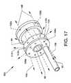
- FIG. 17is an illustration similar in many respects to FIG. 13 showing an isometric view of the alternative fluid jet emanator 52 c connected to and in communication with the high pressure tube 50 .
- a plurality of distally (forwardly) directed jet orifices 122 a - 122 nis additionally located on and about the distal face of the fluid jet emanator 52 c .
- the plurality of small sized radially directed jet orifices 112 a - 112 nis also included about the periphery of the fluid jet emanator 52 c .
- the fluid jet emanator 52 calso includes the plurality of proximally (rearwardly) directed jet orifices 106 a - 106 n located on and about the proximal face of the fluid jet emanator 52 c , as well as including the previously described annular groove 84 and passageway 86 .
- the plurality of radially directed jet orifices 112 a - 112 n , the plurality of proximally directed orifices 106 a - 106 n and the plurality of distally directed jet orifices 122 a - 122 nare in common and are pressurized in common by pressurized saline provided through the high pressure tube 50 .
- the high pressure tube 50delivers pressurized saline or other suitable fluids to the fluid jet emanator 52 c to produce and distribute high pressure distally directed fluid jet streams 126 which emanate from the distally directed jet orifices 122 a - 122 n in order to provide for the automatic pressurization and inflation of the balloon 118 as shown in FIG. 18 .
- the high pressure tube 50delivers pressurized saline or other suitable fluid to the fluid jet emanator 52 c for producing and distributing high velocity but small sized radially directed fluid jet streams 114 of saline or other suitable fluids which emanate from the radially directed jet orifices 112 a - 112 n of the fluid jet emanator 52 c to vigorously and more powerfully perform functions, as described herein.
- the fluid jet emanator 52 calso produces and distributes pressurized proximally directed fluid jet streams 108 of saline or other suitable fluids which are directed proximally from the proximally directed orifices 106 a - 106 n to perform functions, as described herein.
- a normal guidewire 37is deployed in a blood vessel 96 requiring treatment.
- the catheter tube 12 c and other closely associated and aligned components directly associated therewithconsisting mainly of the high pressure tube 50 , the fluid jet emanator 52 c , the distal section of the catheter tube 12 c , and the uninflated balloon 118 are advanced over and along the guidewire ( 37 ) and aligned within the blood vessel 96 for the purpose of cell harvesting, debris/thrombus/lesion maceration or removal, drug infusion, or other procedures; the catheter tube is maneuvered into an appropriate position within the blood vessel 96 for treatment.
- a generic guide catheter or sheathcan be incorporated as necessary to offer assistance in placing the catheter tube 12 c and closely aligned components in direct association therewith of the direct stream hydrodynamic catheter system 10 c within the desired location of the blood vessel 96 in order that the tapered flexible tip 40 of the catheter tube 12 c can be extended through the thrombus or lesions 98 to a position where the fluid jet emanator 52 c is in very close proximity to the thrombus or lesions 98 and where the self-inflating balloon 118 is distal to the thrombus or lesions 98 .
- FIG. 18is a side view, in partial cross section, of the catheter tube 12 c of the third alternative embodiment of the present disclosure illustrating the performance of the method and use thereof which utilizes enabling connections and which utilizes functions of the accompanying components in a manner similar to that shown in FIG. 1 with particular attention given to the distal section of the catheter tube 12 c , the flexible tapered tip 40 , the inflated self-inflated balloon 118 ( a ), the balloon inflation inflow orifice(s) 116 (reoriented), the fluid jet emanator 52 c , the inflow orifice(s) 38 , and other closely associated components positioned in the blood vessel 96 containing deposits of thrombus or lesions 98 .
- one or more inflow orifice(s) 38 (reoriented)are shown at the top and the bottom of the catheter tube 12 c.
- the distal portion of the high pressure tube 50delivers pressured saline or other suitable fluid to the fluid jet emanator 52 c to produce and distribute radially directed fluid jet streams 114 of saline or other suitable fluids which emanate as direct fluid jet streams from the radially directed jet orifices 112 a - 112 n of the fluid jet emanator 52 c to accomplish thrombectomy functions in a manner as previously described.
- Pressured saline, or other suitable fluidis also delivered by the high pressure tube 50 to the fluid jet emanator 52 c to produce and distribute proximally directed fluid jet streams 108 of saline or other suitable fluids which are directed proximally from the proximally directed jet orifices 106 a - 106 n ( FIG. 17 ) of the fluid jet emanator 52 c , and to thence transit parallel to the inflow orifice(s) 38 , and finally into the distal section of the catheter tube 12 c to flow proximally therethrough in a manner as previously described.
- pressurized saline or other suitable fluidis also delivered by the high pressure tube 50 to the fluid jet emanator 52 c to produce and distribute distally directed fluid jet streams 126 of saline or other suitable fluids which are directed distally from the distally directed jet orifices 122 a - 122 n ( FIG. 17 ) in order to assist in the inflation of the balloon 118 .
- the distally directed fluid jet streams 126 of saline or other suitable fluidswhich are directed distally from the orifices 122 a - 122 n ( FIG. 17 ) of the fluid jet emanator 52 c within and along the distal section of the catheter tube 12 c in close proximity to the balloon inflation inflow orifice 116 and thence within the confines of the self-inflating balloon 118 result in the inflation of balloon 118 a for the purposes of, but not limited to, impeding fluid flow within the blood vessel 96 to effect a stagnate fluid flow in the thrombus region, to provide centering of the distal section of the catheter tube 12 c , and to assist in the accomplishment of thrombectomy functions, as described herein.
- the self-inflating balloon 118is automatically and expandingly deployed to reform as an inflated balloon 118 a primarily by the pressure of the distally directed fluid jet streams 126 emanating from the jet orifices 122 a - 122 n of the fluid jet emanator 52 c .
- the fluid entrainment inflowshown by the directed arrows 128 in FIG. 18 assists in the inflation of the self-inflating balloon 118 .
- Pressurized inflation of the inflated balloon 118 a or maintaining a state of inflationis also assisted by utilizing back pressure along the length of the catheter tube 12 c .
- An operational advantage of this third alternative embodimentis the utilization of the exhaust outflow and internal pressure which is produced by the proximally directed fluid jet stream(s) 108 in combination with the restriction of the outflow, such as caused by the exhaust regulator 47 , to assist in the automatic expansion of the balloon 118 which expanded balloon 118 a forcibly impinges upon and seals against the inner wall of the blood vessel 96 .
- the reduced thickness of the material comprising the balloon 118allows the balloon 118 to expand sufficiently to become an inflated balloon 118 a restricted by its impingement upon the wall of the blood vessel 96 .
- the inflation pressure and fluid flowscan be influenced by controlling the input fluid pressure at the high pressure fluid source 42 and/or by controlling the exhaust rate at the exhaust regulator 47 .
- fluid jet emanatorsof appropriate size and/or configuration can be incorporated in lieu of the fluid jet emanator 52 c within the proximal end of the distal section of the catheter tube 12 c in order to emanate or emit one or more distally directed fluid jet streams 126 , to emanate or emit one or more proximally directed fluid jet streams 108 along or near the longitudinal axis of the catheter tube 12 c , and to emanate or emit one or more radially directed fluid jet streams 114 therefrom.
- Inflation of the balloon 118 to form the inflated balloon 118 apositions the peripheral circumference of the inflated balloon 118 against the wall of the blood vessel 96 in order to effect a fluid flow reduction or cessation within the blood vessel 96 .
- the inflated balloon 118 ai.e., the balloon 118 , can be compliant, semi-compliant, or noncompliant according to the procedure performed.
- the inflated balloon 118 aprovides uniform centering and positioning of the distal section of the catheter tube 12 c within the blood vessel 96 , thereby providing a substantially equal annular spacing between the wall of the blood vessel 96 and the inflow orifice 38 for uniform access and clearance thereto and thereabout.
- the inflated balloon 118 aalso provides for an annular spacing between the blood vessel 96 and the balloon inflation inflow orifice 116 in order to provide access and clearance to and about the balloon inflation inflow orifice 116 .
- the proximally directed fluid jet streams 108provide a low pressure region at the inflow orifice 38 to ingest and entrain thrombotic particulate and/or debris 98 therethrough to impinge upon, provide drag forces on, and break up or macerate thrombotic particulate and/or debris 98 , and by entrainment to urge and carry along one or more particles of thrombotic particulate and/or debris or lesion particulate 98 along the lumen 53 of the catheter tube 12 c by the action of the proximally directed fluid jet streams 108 .
- the entrainment of thrombotic particulate and/or debris 98 through the inflow orifice 38is dependent on the high velocity fluid jet streams 108 .
- the outflow of fluid and thrombusis generally driven proximally through the catheter tube 12 c by an internal pressure which is produced by the high velocity fluid jet streams 108 and the fluid entrained through the inflow orifice 38 but also uses the assistance of fluid pressure forces provided by the radially directed fluid jet streams 114 , the distally directed fluid jet streams 126 and assistance provided by aspiration.
- the balloon 118can be alternately pressurized and depressurized whereby the thrombus or lesions 98 can be compacted in order to enlarge a passage through the blood vessel 96 .
- the catheter tube 12 cmay be moved proximally or distally during the procedure to maximize the effect of the catheter system.
- the inflated balloon 118 ais generally deflated sufficiently under normal arterial pressure so that the balloon 118 can be removed safely, or deflation of the balloon 118 can be aided with a manual syringe attached to the manifold, or deflation of the balloon 118 can be aided by means of the exhaust regulator 47 .
- Other known interventionscan be executed over the remaining guidewire or guidewire device.
- Cessation of fluid flow in a blood vessel or other conduitmaximizes the effect of the catheter system 10 c in terms of debris or tissue removal.
- Use of devices of the present disclosurecan also provide for the performance of a modified embolectomy by breaking up clots as the inflated balloon 118 a is moved through a blocked vessel or can be used to minimize any distal or proximal embolization.
- the radially directed fluid jet streams 114 , the proximally directed fluid jet streams 108 and the distally directed fluid jet streams 126are driven by the same fluid pressure.
- the velocity of the fluid jet streamsis controllingly influenced by the high pressure pump 44 and the total area of all of the radially directed jet orifices 112 a - 112 n , the proximally directed jet orifices 106 a - 106 n and the distally directed jet orifices 122 a - 122 n .
- Debris and sample removalare influenced by and assisted by aspiration in coordination with the operation of the high pressure fluid pump 44 and the exhaust regulator 47 which simultaneously introduces pressurized radially, proximally and distally directed fluid jet streams into the distal end of the catheter tube 12 c .
- the inflow orifice 38is sufficiently sized for aspiration to be effected.
- the velocity and strength of the radially directed fluid jet streams 114 , the proximally directed fluid jet streams 108 and the distally directed fluid jet streams 126can be influenced and controlled.
- the principle for aggressive debris removalis dependent upon the velocity of the radially directed fluid jet streams 114 . Consider that there is some critical velocity for debris liberation.
- the fluid jet streams 114As the radially directed fluid jet streams 114 travel through a fluid environment the fluid jet streams will entrain surrounding fluid whereby the fluid jet streams will slow.
- the velocity of the fluid jet streamsis proportional to the diameter of the jet streams and to the initial velocity of the fluid jet streams.
- the velocity of the fluid jet streamscould be increased by either increasing the initial fluid jet stream velocity or increasing the jet orifice diameter.
- the catheter systemis designed with a given set of jet orifice diameters and the high pressure pump 44 pump rate is adjusted to achieve the proper efficacy.
- the velocity of the radially directed fluid jet streams 114can be increased sufficiently to liberate microscopic rafts of cell clumps.
- the use of the distally located occlusion balloon 118 ais helpful in ensuring that the liberated conduit cells do not migrate to distal vascular beds. For example, if the cells were cancerous ureter epithelial cells, the balloon 118 a would minimize the chance for metastasizing.
- FIG. 19a fourth alternative, is an illustration similar in many respects to FIG. 2 showing a direct stream hydrodynamic catheter tube 12 d , also referred to as the catheter tube 12 d , and the manifold 14 and components associated therewith and wherein each is connected to and which utilizes functions of the accompanying enabling components in a manner similar to that shown in FIG. 1 where all numerals correspond to those elements previously described or as otherwise described herein.
- the catheter tube 12is reconfigured as a catheter tube 12 d to additionally include one or more outflow orifice(s) 130 located in the distal portion of the catheter tube 12 d at a location distal to a fluid jet emanator 52 d , as best shown in FIG. 20 .
- the outflow orifices 130are utilized to provide low power direct streams in the form of cross stream jets 132 referenced in FIG. 22 .
- the radially directed jet orifices 112 a - 112 n and the radially directed fluid jet streams 114are not utilized in this alternative embodiment.
- the components of FIG. 19are used with the enabling components referred to and shown in FIG. 1 where such enabling components consist of the high pressure fluid source 42 , the high pressure fluid pump 44 , the threaded high pressure connection port 32 and connector 46 , the exhaust regulator 47 , the collection chamber 48 , and the connector 49 which are used in much the same manner as previously described.
- the referenced enabling components in combination with the catheter tube 12 d and the manifold 14 and closely associated components thereofcomprise a direct stream hydrodynamic catheter system 10 d which is also referred to as the catheter system 10 d , wherein the catheter system 10 d provides for the use of a decreased velocity but large sized cross stream jets 132 therefrom by using outflow orifice(s) 130 .
- the catheter system 10 dincludes the provision of and the use of the previously described pressurized proximally directed fluid jet streams 108 and the pressurized distally directed fluid jet streams 126 which emanate from the fluid jet emanator 52 d ( FIG.
- FIG. 20is an illustration similar in many respects to FIG. 4 showing the distal end of a catheter tube 12 d reconfigured and used in lieu of the catheter tube 12 and shown in use with the fluid jet emanator 52 d in lieu of the fluid jet emanator 52 , wherein the fluid jet emanator 52 d includes many of the structural features and much of the functionality such as described for FIG. 21 . Shown more specifically is the relationship and arrangement of the inflow orifice 38 (reoriented), the proximally directed jet orifices 106 a - 106 n of the fluid jet emanator 52 d , the distally directed jet orifices 122 a - 122 n of the fluid jet emanator 52 d and the outflow orifice(s) 130 .
- the plurality of radially directed jet orifices 112 a - 112 n for the emanation of radially directed jet streams 114is not included in the fluid jet emanator 52 d and the plurality of holes 94 a - 94 n of the previously shown catheter tubes 12 a - 12 c is not included in the catheter tube 12 d.
- FIG. 21is an illustration similar in many respects to FIG. 17 showing an isometric view of the alternative fluid jet emanator 52 d connected to and in communication with the high pressure tube 50 .
- the plurality of distally (forwardly) directed jet orifices 122 a - 122 nis located on and about the distal face of the fluid jet emanator 52 d .
- the previously shown and described plurality of proximally (rearwardly) directed jet orifices 106 a - 106 nlocated on and about the proximal face of the fluid jet emanator 52 d .
- the fluid jet emanator 52 dalso includes the previously described annular groove 84 and passageway 86 .
- the plurality of proximally directed orifices 106 a - 106 n and the plurality of distally directed jet orifices 122 a - 122 nare in common and are pressurized in common by pressurized saline provided through the high pressure tube 50 .
- the high pressure tube 50delivers high pressure saline or other suitable fluids to the fluid jet emanator 52 d to produce and distribute pressurized distally directed fluid jet streams 126 which emanate from the distally directed jet orifices 122 a - 122 n in order to provide for the generation of cross stream jets 132 used for thrombus or lesion treatment ( FIG. 22 ).
- the high pressure tube 50delivers pressurized saline or other suitable fluid to the fluid jet emanator 52 d for producing and distributing pressurized proximally directed fluid jet streams 108 of saline or other suitable fluids which fluid jet streams are directed proximally from the proximally directed orifices 106 a - 106 n to perform functions, as described herein.
- a normal guidewire 37is deployed in a blood vessel 96 requiring treatment, or in the alternative, a filter guidewire or balloon occlusion guidewire could also be used.
- the catheter tube 12 d and other closely associated and aligned components directly associated therewithconsisting mainly of the high pressure tube 50 , the fluid jet emanator 52 d and the distal section of the catheter tube 12 d are advanced over and along the guidewire ( 37 ) and aligned within the blood vessel 96 for the purpose of debris/thrombus/lesion maceration or removal, drug infusion, or other procedures; the catheter tube is maneuvered into an appropriate position within the blood vessel 96 for treatment.
- a generic guide catheter or sheathcan be incorporated as necessary to offer assistance in placing the catheter tube 12 d and closely aligned components in direct association therewith of the direct stream hydrodynamic catheter system 10 d within the desired location of the blood vessel 96 in order that the tapered flexible tip 40 of the catheter tube 12 d can be extended through the thrombus or lesions 98 to a position where the fluid jet emanator 52 d is in very close proximity to the thrombus or lesions 98 .
- the direct stream thrombectomy catheter system 10 dis then activated, whereby thrombus, debris and the like can be removed by action of the cross stream jet(s) 132 preferably in association with other methods previously described or drugs can be infused by a desired procedure.
- FIG. 22is a side view of the fourth alternative embodiment, in partial cross section, of the catheter tube 12 d in the performance of the method and use thereof which utilizes enabling connections and which utilizes functions of the accompanying components in a manner similar to that shown in FIG. 1 with particular attention given to the distal section of the catheter tube 12 d , the flexible tapered tip 40 , the outflow orifice(s) 130 (reoriented), the fluid jet emanator 52 d , the inflow orifice(s) 38 , and other closely associated components positioned in the blood vessel 96 containing deposits of thrombus or lesions 98 .
- one or more inflow orifice(s) 38 (reoriented) and the outflow orifice 130 (reoriented)are shown at the top and the bottom of the catheter tube 12 d.
- Pressured saline or other suitable fluidis delivered by the high pressure tube 50 to the fluid jet emanator 52 d to produce and distribute proximally directed fluid jet streams 108 of saline or other suitable fluids which are directed proximally from the proximally directed jet orifices 106 a - 106 n ( FIG. 21 ) of the fluid jet emanator 52 d , and to thence transit parallel to the inflow orifice(s) 38 , and finally into the distal section of the catheter tube 12 d to flow proximally in a manner as previously described.
- pressurized saline or other suitable fluidis also delivered by the high pressure tube 50 to the fluid jet emanator 52 d to produce and distribute distally directed fluid jet streams 126 of saline or other suitable fluids employed for a use different from the previously described embodiments, whereby the distally directed fluid jet streams 126 are directed distally from the distally directed jet orifices 122 a - 122 n ( FIG. 21 ) in order to provide for the generation of the cross stream jets 132 .
- the distally directed fluid jet streams 126 of saline or other suitable fluidsare directed toward the general location of the outflow orifice(s) 130 and within and along the co-located distal end of the catheter tube 12 d .
- the distally directed fluid jet streams 126are pressurized at the distal end of the catheter tube 12 d and exit the outflow orifice(s) 130 as cross stream jets 132 which re-enter the catheter tube 12 d through the inflow orifice(s) 38 .
- the cross stream jets 132serve to impinge upon the thrombus or lesion 98 in order to abrade, ablate, break up and entrain such thrombus or lesion 98 particulate and to entrain and carry such treated particulate into the inflow orifice(s) 38 .
- Other fluid jet emanators of appropriate size and/or configurationcan be incorporated in lieu of the fluid jet emanator 52 d within the proximal end of the distal section of the catheter tube 12 d to emanate or emit one or more distally directed fluid jet streams 126 distally for the purpose of providing cross stream jets 132 and to emanate or emit one or more proximally directed fluid jet streams 108 along or near the longitudinal axis of the catheter tube 12 d.
- the proximally directed fluid jet streams 108provide for creating a low pressure region at the inflow orifice 38 for re-entry of the cross stream jet(s) 132 and, as before, provide for the ingestion and entrainment of thrombus or lesion 98 particulate and/or debris therethrough.
- the proximally directed fluid jet streams 108impinge upon, provide drag forces on, and break up or macerate thrombus or lesion 98 particulate and/or debris and by entrainment urge and carry along one or more particles of thrombus or lesion 98 and/or debris along the lumen 53 of the catheter tube 12 d .
- the entrainment of thrombotic particulate and/or debris 98 through the inflow orifice 38is dependent on the high velocity fluid jet streams 108 .
- the outflow of fluid and thrombusis generally driven proximally through the catheter tube 12 d by an internal pressure which is produced by the high velocity fluid jet streams 108 and the fluid entrained through the inflow orifice 38 , but also uses the assistance of fluid pressure forces provided by the distally directed fluid jet streams 126 and closely associated cross stream jets 132 .
- the proximally directed jet streams 108 and the distally directed fluid jet streams 126 which produce the cross stream jets 132are driven by the same fluid pressure.
- the velocity of the fluid jet streamsis controllingly influenced by the high pressure pump 44 and the total area of all of the proximally directed jet orifices 106 a - 106 n and the distally directed jet orifices 122 a - 122 n .
- Debris removalis influenced by and assisted by aspiration in coordination with the operation of the high pressure fluid pump 44 and the exhaust regulator 47 which simultaneously introduces pressurized proximally and distally directed fluid jet streams and cross jet streams into and from the distal end of the catheter tube 12 d .
- the inflow orifice 38is sufficiently sized for aspiration.
- the velocity and strength of the proximally directed fluid jet streams 108 and the distally directed fluid jet streams 126 and the cross stream jets 132can be influenced and controlled.
- the principle for aggressive thrombus ablation and breakup, as well as for debris removal,is dependent on the velocity of the cross stream jets 132 . Consider that there is some critical velocity for debris liberation.
- the cross stream jets 132will entrain surrounding fluid whereby the cross stream jets 132 will slow.
- the velocity of the jet streamsis proportional to the diameter of the fluid jet streams and to the initial velocity of the fluid jet streams.
- the velocity of the fluid jet streams at a given distance within the blood vessel 96would be increased by either increasing the velocity of the distally directed fluid jet streams 126 or increasing the diameter of the distally directed jet orifice 122 a - 122 n .
- the pump rate of the high pressure pump 44would need to be increased in order to maintain the fluid jet stream velocity.
- the catheter systemis designed with a given set of jet orifice diameters and with the pump rate of the high pressure pump 44 adjusted to achieve the proper efficacy.
- FIG. 23a fifth alternative embodiment, is an illustration similar in many respects to FIG. 2 showing a direct stream hydrodynamic catheter tube 12 e , also referred to as the catheter tube 12 e and the manifold 14 and components associated therewith and wherein is connected to and which utilizes functions of the accompanying enabling components in a manner similar to that shown in FIG. 1 where all numerals correspond to those elements previously described or as otherwise described herein.
- a direct stream hydrodynamic catheter tube 12 ealso referred to as the catheter tube 12 e and the manifold 14 and components associated therewith and wherein is connected to and which utilizes functions of the accompanying enabling components in a manner similar to that shown in FIG. 1 where all numerals correspond to those elements previously described or as otherwise described herein.
- the catheter tube 12is reconfigured as a catheter tube 12 e excluding the tapered tip 40 , excluding the use of the radially directed jet orifices 112 a - 112 n in the fluid jet emanator 52 e , excluding the use of high powered radially directed fluid jet streams 114 , and excluding the holes 94 a - 94 n at the distal end of the catheter tube 12 e .
- This fifth alternative embodimentfeatures the use of multiple distally directed jet streams 126 as a method of parting, projecting through and breaking up the thrombus or lesions 98 .
- the components of FIG. 23are used with the enabling components referred to and shown in FIG.
- the referenced enabling components in combination with the catheter tube 12 e and the manifold 14 and closely associated components thereofcomprise a direct stream hydrodynamic catheter system 10 e which is also referred to as the catheter system 10 e , wherein the catheter system 10 e provides for substantially the brute force of distally directed fluid jet streams 126 in combination.
- the catheter system 10 eincludes the provision of and the use of the previously described pressurized proximally directed fluid jet streams 108 , the pressurized distally directed fluid jet streams 126 which emanate from the fluid jet emanator 52 e ( FIG. 25 ), wherein a numerically large number of distally directed fluid jet streams 126 part and disrupt thrombus or lesions 98 and pass therethrough generally in a tunneling manner.
- the catheter tube 12 e , the manifold 14 , and closely associated components of eachare shown referenced to the catheter system 10 e in FIG. 23 , it is understood that the previously referenced enabling components referred to and shown in FIG. 1 , but not shown in FIG. 23 , are also part of the catheter system 10 e.
- FIG. 24is an illustration similar in many respects to FIG. 4 showing the distal end of a catheter tube 12 e reconfigured and used in lieu of the catheter tube 12 and shown with the fluid jet emanator 52 e used in lieu of the fluid jet emanator 52 , wherein the fluid jet emanator 52 e includes many of the structural features and much of the functionality such as described in FIG. 25 . Shown more specifically is the relationship and arrangement of the inflow orifice 38 (reoriented), the proximally directed jet orifices 106 a - 106 n of the fluid jet emanator 52 e , the distally directed jet orifices 122 a - 122 n of the fluid jet emanator 52 e and the open end 134 of the catheter tube 12 e .
- the plurality of radially directed jet orifices 112 a - 112 n in the fluid jet emanator 52 e and the plurality of holes 94 a - 94 n of the previously shown catheter tubes 12 a - 12 care not included in the catheter tube 12 e.
- FIG. 25is an illustration similar in many respects to FIG. 17 showing an isometric view of the alternative fluid jet emanator 52 e connected to and in communication with the high pressure tube 50 .
- the large number of distally (forwardly) directed jet orifices 122 a - 122 nis located on and about the distal face of the fluid jet emanator 52 e .
- the previously shown and described plurality of proximally (rearwardly) directed jet orifices 106 a - 106 nlocated on and about the proximal face of the fluid jet emanator 52 e .
- the fluid jet emanator 52 ealso includes the previously described annular groove 84 and passageway 86 .
- the plurality of proximally directed jet orifices 106 a - 106 n and the plurality of distally directed jet orifices 122 a - 122 nare in common and are pressurized in common by pressurized saline provided through the high pressure tube 50 .
- the high pressure tube 50delivers pressurized saline or other suitable fluids to the fluid jet emanator 52 e to produce and distribute multiple high pressurize distally directed jet streams 126 which emanate from the distally directed jet orifices 122 a - 122 n in order to provide for the direct fluid stream impingement of the thrombus or lesions 98 ( FIG. 22 ).
- the high pressure tube 50delivers pressurized saline or other suitable fluid to the fluid jet emanator 52 e for producing and distributing pressurized, proximally directed, fluid jet streams 108 of saline or other suitable fluids which emanate from the proximally directed orifices 106 a - 106 n of the fluid jet emanator 52 e to perform functions, as described herein.
- a normal guidewire 37is deployed in a blood vessel 96 requiring treatment, or in the alternative, a filter guidewire or balloon occlusion guidewire could also be used.
- the catheter tube 12 e and other closely associated and aligned components directly associated therewithconsisting mainly of the high pressure tube 50 , the fluid jet emanator 52 e , and the distal section of the catheter tube 12 e are advanced over and along the guidewire ( 37 ) and aligned within the blood vessel 96 for the purpose of debris/thrombus/lesion maceration or removal, drug infusion, or other procedures; the catheter system 12 e is maneuvered into an appropriate position within the blood vessel 96 for treatment.
- a generic guide catheter or sheathcan be incorporated as necessary to offer assistance in placing the catheter tube 12 e and closely aligned components in direct association therewith of the direct stream hydrodynamic catheter system 10 e within the desired location of the blood vessel 96 in order that the distally located open end 134 of the catheter tube 12 e can be brought in close proximity or in intimate contact with the proximal end of the thrombus or lesions 98 , and then by operation of the catheter system, be extended through the thrombus or lesions 98 .
- the direct stream thrombectomy catheter system 10 eis then activated, whereby thrombus, debris and the like can be removed by action of the low pressure region at the inflow orifice(s) 38 , preferably in association with other methods as previously described, or drugs can be infused by a desired procedure.
- FIG. 26is a side view, in partial cross section, of the catheter tube 12 e of the fifth alternative embodiment of the present disclosure illustrating the performance of the method and use thereof which utilizes enabling connections and which performance utilizes functions of the accompanying components in a manner similar to that shown in FIG. 1 with particular attention given to the distal section of the catheter tube 12 e , especially the open end 134 thereof, the fluid jet emanator 52 e , the inflow orifice(s) 38 , and other closely associated components positioned in the blood vessel 96 containing deposits of thrombus or lesions 98 .
- one or more inflow orifice(s) 38is shown at the top and the bottom of the catheter tube 12 e.
- Pressured saline or other suitable fluidis delivered by the high pressure tube 50 to the fluid jet emanator 52 e ( FIG. 25 ) to produce and distribute proximally directed fluid jet streams 108 of saline or other suitable fluids which are directed proximally from the proximally directed jet orifices 106 a - 106 n ( FIG. 25 ) of the fluid jet emanator 52 e , and to thence transit parallel to the inflow orifice(s) 38 , and finally into the distal section of the catheter tube 12 e to flow proximally in a manner as previously described.
- pressurized saline or other suitable fluidis also delivered by the high pressure tube 50 to the fluid jet emanator 52 e to produce and distribute multiple distally directed fluid jet streams 126 of saline or other suitable fluids employed for a use different from uses of previously described embodiments, whereby the distally directed jet streams 126 in large numbers are directed distally from the distally directed jet orifices 122 a - 122 n ( FIG. 21 ) in order to forcibly abrade, ablate, part, break up, tunnel and pass through the thrombus or lesion 98 and to make, provide and use a passage therethrough.
- the pressurized distally directed jet streams 126can re-enter the catheter tube 12 e through the inflow orifice(s) 38 .
- the thrombus or lesions 98are entrained and carried into the inflow orifice(s) 38 by the low pressure region at the inflow orifice(s) 38 .
- a guidewire having a distally deployed ballooncan be beneficial in aiding in the flow of thrombus and lesion 98 proximally through the inflow orifice(s) 38 .
- Other fluid jet emanators of appropriate size and/or configurationcan be used in lieu of the fluid jet emanator 52 e within the distal section of the catheter tube 12 e to emanate or emit multiple distally directed fluid jet streams 126 for the purpose of ablation, removal, breakup and the like of thrombus or lesions 98 and providing a path therethrough and for emanating or emitting one or more proximally directed fluid jet streams 108 along or near the longitudinal axis of the catheter tube 12 e.
- the proximally directed fluid jet streams 108provide a low pressure region at the inflow orifice 38 for re-entry of thrombus or lesion 98 particulate and, as before, to ingest and entrain such thrombotic or lesion particulate and/or debris 98 therethrough to impinge upon, provide drag forces on, and break up or macerate thrombotic particulate and/or debris 98 , and by entrainment to urge and carry along one or more particles of thrombotic particulate and/or debris 98 or lesion particulate along the lumen 53 of the catheter tube 12 e by the action of the proximally directed fluid jet streams 108 .
- the entrainment of thrombotic particulate and/or debris 98 through the inflow orifice 38is dependent on entrainment by the high velocity fluid jet streams 108 .
- the outflow of fluid and thrombusis generally driven proximally through the catheter tube 12 e by an internal pressure which is produced by the high velocity fluid jet streams 108 and the fluid entrained through the inflow orifice 38 , but also uses the assistance of fluid pressure forces provided by the distally directed fluid jet streams 126 .
- the proximally directed fluid jet streams 108 and the distally directed fluid jet streams 126are driven by the same fluid pressure force.
- the velocity of the fluid jet streamsis controllingly influenced by the high pressure pump 44 and the total area of all of the proximally directed jet orifices 106 a - 106 n and the distally directed jet orifices 122 a - 122 n .
- Debris removalis influenced by and assisted by aspiration in coordination with the operation of the high pressure fluid pump 44 and the exhaust regulator 47 which simultaneously introduce pressurized proximally and distally directed fluid jet streams into the distal end of the catheter tube 12 e , as well as providing for the flow of the cross stream jets 136 .
- the inflow orifice 38is sufficiently sized for aspiration.
- the velocity and strength of the proximally directed fluid jet streams 108 and the distally directed fluid jet streams 126can be influenced and controlled.
- the principle for aggressive thrombus ablation and breakup, as well as for debris removal,is dependent on the velocity of the distally directed fluid jet streams 126 . Consider that there is some critical velocity for debris liberation.
- the distally directed fluid jet stream 126will entrain surrounding fluid thus causing the distally directed fluid jet stream 126 to slow.
- velocity of the fluid jet streamsis proportional to the diameter of the fluid jet streams and to the initial velocity of the fluid jet streams.
- the velocity of the fluid jet streams at a given distancecould be increased by either increasing the initial velocity of the distally directed fluid jet streams 126 or increasing the jet orifice diameter.
- the pump rate of the high pressure fluid pump 44would need to be increased to maintain the jet stream velocity.
- the catheter systemis designed with a given set of jet orifice diameters and the pump rate of the high pressure fluid pump 44 is adjusted to achieve the proper efficacy.
Landscapes
- Health & Medical Sciences (AREA)
- Life Sciences & Earth Sciences (AREA)
- Animal Behavior & Ethology (AREA)
- Veterinary Medicine (AREA)
- Engineering & Computer Science (AREA)
- Public Health (AREA)
- Biomedical Technology (AREA)
- Heart & Thoracic Surgery (AREA)
- General Health & Medical Sciences (AREA)
- Surgery (AREA)
- Hematology (AREA)
- Anesthesiology (AREA)
- Pulmonology (AREA)
- Biophysics (AREA)
- Vascular Medicine (AREA)
- Nuclear Medicine, Radiotherapy & Molecular Imaging (AREA)
- Medical Informatics (AREA)
- Molecular Biology (AREA)
- Media Introduction/Drainage Providing Device (AREA)
- Surgical Instruments (AREA)
- External Artificial Organs (AREA)
Abstract
Description
Claims (16)
Priority Applications (1)
| Application Number | Priority Date | Filing Date | Title |
|---|---|---|---|
| US12/933,520US8647294B2 (en) | 2008-03-20 | 2009-03-20 | Direct stream hydrodynamic catheter system |
Applications Claiming Priority (3)
| Application Number | Priority Date | Filing Date | Title |
|---|---|---|---|
| US7009508P | 2008-03-20 | 2008-03-20 | |
| PCT/US2009/037814WO2009117663A2 (en) | 2008-03-20 | 2009-03-20 | Direct stream hydrodynamic catheter system |
| US12/933,520US8647294B2 (en) | 2008-03-20 | 2009-03-20 | Direct stream hydrodynamic catheter system |
Related Parent Applications (1)
| Application Number | Title | Priority Date | Filing Date |
|---|---|---|---|
| PCT/US2009/037814A-371-Of-InternationalWO2009117663A2 (en) | 1998-02-06 | 2009-03-20 | Direct stream hydrodynamic catheter system |
Related Child Applications (1)
| Application Number | Title | Priority Date | Filing Date |
|---|---|---|---|
| US14/176,814DivisionUS9586023B2 (en) | 1998-02-06 | 2014-02-10 | Direct stream hydrodynamic catheter system |
Publications (2)
| Publication Number | Publication Date |
|---|---|
| US20110015564A1 US20110015564A1 (en) | 2011-01-20 |
| US8647294B2true US8647294B2 (en) | 2014-02-11 |
Family
ID=41091557
Family Applications (3)
| Application Number | Title | Priority Date | Filing Date |
|---|---|---|---|
| US12/933,520Active2029-08-19US8647294B2 (en) | 2008-03-20 | 2009-03-20 | Direct stream hydrodynamic catheter system |
| US16/440,949Active2030-08-21US11464941B2 (en) | 2008-03-20 | 2019-06-13 | Direct stream hydrodynamic catheter system |
| US17/962,785Active2029-11-23US12420060B2 (en) | 2008-03-20 | 2022-10-10 | Direct stream hydrodynamic catheter system |
Family Applications After (2)
| Application Number | Title | Priority Date | Filing Date |
|---|---|---|---|
| US16/440,949Active2030-08-21US11464941B2 (en) | 2008-03-20 | 2019-06-13 | Direct stream hydrodynamic catheter system |
| US17/962,785Active2029-11-23US12420060B2 (en) | 2008-03-20 | 2022-10-10 | Direct stream hydrodynamic catheter system |
Country Status (3)
| Country | Link |
|---|---|
| US (3) | US8647294B2 (en) |
| DE (1) | DE112009000700B4 (en) |
| WO (1) | WO2009117663A2 (en) |
Cited By (18)
| Publication number | Priority date | Publication date | Assignee | Title |
|---|---|---|---|---|
| US9248221B2 (en) | 2014-04-08 | 2016-02-02 | Incuvate, Llc | Aspiration monitoring system and method |
| US9433427B2 (en) | 2014-04-08 | 2016-09-06 | Incuvate, Llc | Systems and methods for management of thrombosis |
| USD808013S1 (en) | 2016-10-27 | 2018-01-16 | Smiths Medical Asd, Inc. | Catheter |
| US9883877B2 (en) | 2014-05-19 | 2018-02-06 | Walk Vascular, Llc | Systems and methods for removal of blood and thrombotic material |
| US10226263B2 (en) | 2015-12-23 | 2019-03-12 | Incuvate, Llc | Aspiration monitoring system and method |
| US10531883B1 (en) | 2018-07-20 | 2020-01-14 | Syntheon 2.0, LLC | Aspiration thrombectomy system and methods for thrombus removal with aspiration catheter |
| US10561440B2 (en) | 2015-09-03 | 2020-02-18 | Vesatek, Llc | Systems and methods for manipulating medical devices |
| US10675440B2 (en) | 2016-02-18 | 2020-06-09 | Smiths Medical Asd, Inc. | Closed system catheter |
| US10702292B2 (en) | 2015-08-28 | 2020-07-07 | Incuvate, Llc | Aspiration monitoring system and method |
| US11497521B2 (en) | 2008-10-13 | 2022-11-15 | Walk Vascular, Llc | Assisted aspiration catheter system |
| US11510689B2 (en) | 2016-04-06 | 2022-11-29 | Walk Vascular, Llc | Systems and methods for thrombolysis and delivery of an agent |
| US11540847B2 (en) | 2015-10-09 | 2023-01-03 | Incuvate, Llc | Systems and methods for management of thrombosis |
| WO2023057981A1 (en)* | 2021-10-08 | 2023-04-13 | Covidien Lp | Aspiration system including fluid-infusing inner member |
| US11653945B2 (en) | 2007-02-05 | 2023-05-23 | Walk Vascular, Llc | Thrombectomy apparatus and method |
| US11678905B2 (en) | 2018-07-19 | 2023-06-20 | Walk Vascular, Llc | Systems and methods for removal of blood and thrombotic material |
| US12048541B2 (en) | 2018-06-08 | 2024-07-30 | Smiths Medical Asd, Inc. | Blood sequestration device and method |
| US12171445B2 (en) | 2021-02-15 | 2024-12-24 | Walk Vascular, Llc | Systems and methods for removal of blood and thrombotic material |
| US12274458B2 (en) | 2021-02-15 | 2025-04-15 | Walk Vascular, Llc | Systems and methods for removal of blood and thrombotic material |
Families Citing this family (15)
| Publication number | Priority date | Publication date | Assignee | Title |
|---|---|---|---|---|
| US8398579B2 (en) | 2009-12-16 | 2013-03-19 | Medrad, Inc. | Catheter including composite guide and methods for use of the same |
| US9238122B2 (en) | 2012-01-26 | 2016-01-19 | Covidien Lp | Thrombectomy catheter systems |
| US9855375B2 (en)* | 2012-07-10 | 2018-01-02 | Valorisation Recherche Hscm, Limited Partnership | Method and device for infusion of pharmacologic agents and thrombus aspiration in artery |
| US9332998B2 (en) | 2012-08-13 | 2016-05-10 | Covidien Lp | Apparatus and methods for clot disruption and evacuation |
| US9332999B2 (en) | 2012-08-13 | 2016-05-10 | Covidien Lp | Apparatus and methods for clot disruption and evacuation |
| US9108019B2 (en)* | 2013-03-13 | 2015-08-18 | Boston Scientific Limited | Catheter system |
| US9737328B2 (en) | 2013-03-14 | 2017-08-22 | Boston Scientific Limited | Hydrodynamic eccentrically pivoting catheter |
| US9936963B2 (en) | 2014-04-23 | 2018-04-10 | Gyrus Acmi, Inc. | Stone fragment suction device |
| US11931060B2 (en)* | 2018-01-10 | 2024-03-19 | Boston Scientific Scimed, Inc. | Aspiration medical device |
| US20200078564A1 (en)* | 2018-09-10 | 2020-03-12 | Becton, Dickinson And Company | Peripheral intravenous catheter assembly having an extension set |
| WO2020069521A1 (en) | 2018-09-28 | 2020-04-02 | Flow Medical Corporation | Catheter apparatus |
| US11602617B2 (en) | 2019-04-18 | 2023-03-14 | Michael Bonnette | Pumpless thrombectomy system |
| CN117677353A (en) | 2021-05-04 | 2024-03-08 | 波士顿科学国际有限公司 | Aspiration medical device |
| CN114469257B (en)* | 2022-04-02 | 2022-07-01 | 北京华脉泰科医疗器械股份有限公司 | Thrombus removing device |
| CN114470370B (en)* | 2022-04-02 | 2022-07-05 | 北京华脉泰科医疗器械股份有限公司 | Suction catheter |
Citations (214)
| Publication number | Priority date | Publication date | Assignee | Title |
|---|---|---|---|---|
| US1902418A (en) | 1931-11-02 | 1933-03-21 | Jensen Salsbery Lab Inc | Surgical instrument |
| US3435826A (en) | 1964-05-27 | 1969-04-01 | Edwards Lab Inc | Embolectomy catheter |
| US3695208A (en) | 1970-11-16 | 1972-10-03 | Ind Patent Dev Corp | Food storage apparatus for use in water-borne vessels |
| US3752617A (en) | 1969-10-13 | 1973-08-14 | Sherwood Medical Ind Inc | Apparatus for extruding products of plural components of varied proportions with scrap reclamation |
| US3833003A (en) | 1972-07-05 | 1974-09-03 | A Taricco | Intravascular occluding catheter |
| US3930505A (en)* | 1974-06-24 | 1976-01-06 | Hydro Pulse Corporation | Surgical apparatus for removal of tissue |
| US4100246A (en) | 1976-06-21 | 1978-07-11 | Dow Corning Corporation | Method of forming a gastrointestinal tube |
| US4168709A (en) | 1975-03-10 | 1979-09-25 | Bentov Itzhak E | Dilator |
| GB1571459A (en) | 1977-12-20 | 1980-07-16 | Instavac Ltd | Vacuum pumps and vacuum pump assemblies |
| US4224943A (en) | 1979-01-24 | 1980-09-30 | Sorenson Research Co., Inc. | Cannula and method for bidirectional blood flow |
| US4248234A (en) | 1979-03-08 | 1981-02-03 | Critikon, Inc. | Catheter with variable flexural modulus and method of using same |
| US4290428A (en) | 1978-09-01 | 1981-09-22 | Durand Alain J M | Catheter with bulb |
| US4328811A (en) | 1980-07-28 | 1982-05-11 | Fogarty Thomas J | Calibrating dilation catheter |
| US4385635A (en) | 1980-04-25 | 1983-05-31 | Ruiz Oscar F | Angiographic catheter with soft tip end |
| US4515592A (en) | 1980-05-13 | 1985-05-07 | Arrow International, Inc. | Catheter shield |
| US4535757A (en) | 1982-03-12 | 1985-08-20 | Webster Wilton W Jr | Autoinflatable catheter |
| DE3421390C2 (en) | 1984-06-08 | 1986-07-17 | Werner Dr.med. 4330 Mülheim Schubert | High pressure catheter with cutting and / or abrasion device |
| US4610662A (en) | 1981-11-24 | 1986-09-09 | Schneider Medintag Ag | Method for the elimination or the enlargement of points of constriction in vessels carrying body fluids |
| US4631052A (en) | 1984-01-03 | 1986-12-23 | Intravascular Surgical Instruments, Inc. | Method and apparatus for surgically removing remote deposits |
| US4636346A (en) | 1984-03-08 | 1987-01-13 | Cordis Corporation | Preparing guiding catheter |
| US4690672A (en) | 1984-09-06 | 1987-09-01 | Veltrup Elmar M | Apparatus for removing solid structures from body passages |
| US4739768A (en) | 1986-06-02 | 1988-04-26 | Target Therapeutics | Catheter for guide-wire tracking |
| US4747405A (en) | 1984-03-01 | 1988-05-31 | Vaser, Inc. | Angioplasty catheter |
| DE3705339A1 (en) | 1987-02-19 | 1988-09-01 | Siemens Ag | CATHETER FOR TREATING VESSEL NARROWS |
| US4781186A (en) | 1984-05-30 | 1988-11-01 | Devices For Vascular Intervention, Inc. | Atherectomy device having a flexible housing |
| US4782834A (en) | 1987-01-06 | 1988-11-08 | Advanced Cardiovascular Systems, Inc. | Dual lumen dilatation catheter and method of manufacturing the same |
| US4790813A (en) | 1984-12-17 | 1988-12-13 | Intravascular Surgical Instruments, Inc. | Method and apparatus for surgically removing remote deposits |
| US4834710A (en) | 1987-10-08 | 1989-05-30 | Arrow International Investment Corporation | Catheter shield and test structure |
| US4842579A (en) | 1984-05-14 | 1989-06-27 | Surgical Systems & Instruments, Inc. | Atherectomy device |
| US4883459A (en) | 1983-07-29 | 1989-11-28 | Reynaldo Calderon | Retrograde perfusion |
| US4888146A (en) | 1988-05-19 | 1989-12-19 | Dandeneau James V | Method and apparatus of forming extruded article |
| US4898574A (en) | 1986-05-08 | 1990-02-06 | Olympus Optical Co., Ltd. | Lithotomic apparatus |
| US4898591A (en) | 1988-08-09 | 1990-02-06 | Mallinckrodt, Inc. | Nylon-PEBA copolymer catheter |
| US4902276A (en) | 1986-06-09 | 1990-02-20 | The Regents Of The University Of California | Apparatus and method for removing obstructions in bodily organs or cavities |
| US4913698A (en) | 1987-10-26 | 1990-04-03 | Marui Ika Company, Limited | Aqua-stream and aspirator for brain surgery |
| US4917667A (en) | 1988-02-11 | 1990-04-17 | Retroperfusion Systems, Inc. | Retroperfusion balloon catheter and method |
| WO1990005493A1 (en) | 1988-11-15 | 1990-05-31 | Svedman Paal | Surgical instrument |
| US4950238A (en) | 1988-07-07 | 1990-08-21 | Clarence E. Sikes | Hydro-rotary vascular catheter |
| US5011469A (en) | 1988-08-29 | 1991-04-30 | Shiley, Inc. | Peripheral cardiopulmonary bypass and coronary reperfusion system |
| US5015232A (en) | 1989-04-20 | 1991-05-14 | Cook Incorporated | Decompression enteroclysis balloon catheter |
| US5042976A (en) | 1987-01-13 | 1991-08-27 | Terumo Kabushiki Kaisha | Balloon catheter and manufacturing method of the same |
| US5085549A (en) | 1990-12-24 | 1992-02-04 | Ford Motor Company | Three-axis variability compensating fastener |
| US5085635A (en) | 1990-05-18 | 1992-02-04 | Cragg Andrew H | Valved-tip angiographic catheter |
| US5085649A (en) | 1990-11-21 | 1992-02-04 | Flynn Vincent J | Torque controlled tubing |
| US5086842A (en) | 1989-09-07 | 1992-02-11 | Institut Francais Du Petrole | Device and installation for the cleaning of drains, particularly in a petroleum production well |
| US5090960A (en) | 1990-01-12 | 1992-02-25 | Don Michael T Anthony | Regional perfusion dissolution catheter |
| US5092873A (en) | 1990-02-28 | 1992-03-03 | Devices For Vascular Intervention, Inc. | Balloon configuration for atherectomy catheter |
| US5114399A (en) | 1990-10-01 | 1992-05-19 | Intramed Laboratories | Surgical device |
| US5135482A (en) | 1985-12-31 | 1992-08-04 | Arnold Neracher | Hydrodynamic device for the elimination of an organic deposit obstructing a vessel of a human body |
| US5163431A (en) | 1990-04-09 | 1992-11-17 | Cordis Corporation | Angiographic catheter |
| US5171221A (en) | 1991-02-05 | 1992-12-15 | Target Therapeutics | Single lumen low profile valved balloon catheter |
| US5215614A (en) | 1989-06-29 | 1993-06-01 | Cordis Europa N.V. | Method for manufacturing a catheter |
| US5221270A (en) | 1991-06-28 | 1993-06-22 | Cook Incorporated | Soft tip guiding catheter |
| US5222941A (en) | 1990-01-12 | 1993-06-29 | Don Michael T Anthony | Method of dissolving an obstruction in a vessel |
| US5234416A (en) | 1991-06-06 | 1993-08-10 | Advanced Cardiovascular Systems, Inc. | Intravascular catheter with a nontraumatic distal tip |
| US5250059A (en) | 1992-01-22 | 1993-10-05 | Devices For Vascular Intervention, Inc. | Atherectomy catheter having flexible nose cone |
| US5250034A (en) | 1990-09-17 | 1993-10-05 | E-Z-Em, Inc. | Pressure responsive valve catheter |
| US5254107A (en) | 1991-03-06 | 1993-10-19 | Cordis Corporation | Catheter having extended braid reinforced transitional tip |
| US5259842A (en) | 1992-01-25 | 1993-11-09 | Hp-Media Gesellschaft Mgh Fur Medizintechnische Systeme | High-pressure liquid dispenser for the dispensing of sterile liquid |
| US5267979A (en) | 1990-09-17 | 1993-12-07 | E-Z-Em, Inc. | Pressure responsive valve catheter |
| US5273526A (en) | 1991-06-21 | 1993-12-28 | Lake Region Manufacturing Company, Inc. | Vascular occulusion removal devices and method |
| US5300022A (en) | 1992-11-12 | 1994-04-05 | Martin Klapper | Urinary catheter and bladder irrigation system |
| US5306249A (en) | 1990-01-12 | 1994-04-26 | Don Michel T Anthony | Method of treating body passage walls |
| US5308342A (en) | 1991-08-07 | 1994-05-03 | Target Therapeutics, Inc. | Variable stiffness catheter |
| WO1994010917A1 (en) | 1992-11-13 | 1994-05-26 | Drasler William J | Thrombectomy and tissue removal method and device |
| USRE34633E (en) | 1987-11-13 | 1994-06-07 | Cook Incorporated | Balloon guide |
| US5318518A (en) | 1991-08-14 | 1994-06-07 | Hp Medica Gesellschaft Mbh Fur Medizintechnische Systeme | Irrigating catheter |
| US5320599A (en) | 1990-02-14 | 1994-06-14 | Cordis Corporation | Drainage catheter |
| US5324285A (en) | 1989-04-28 | 1994-06-28 | C.B.A. Moulin De Classe | Laser-catheter |
| US5331679A (en) | 1991-12-09 | 1994-07-19 | Kabushiki Kaisha Toshiba | Fuel spacer for fuel assembly |
| US5342386A (en) | 1992-10-26 | 1994-08-30 | Cordis Corporation | Catheter with multiple flexibilities along the shaft |
| US5356388A (en) | 1992-09-22 | 1994-10-18 | Target Therapeutics, Inc. | Perfusion catheter system |
| US5358485A (en) | 1992-01-13 | 1994-10-25 | Schneider (Usa) Inc. | Cutter for atherectomy catheter |
| US5360397A (en) | 1993-07-02 | 1994-11-01 | Corvita Corporation | Hemodiaylsis catheter and catheter assembly |
| US5360379A (en) | 1993-10-25 | 1994-11-01 | Alliedsignal Inc. | Packaging machinery belt with non-directional splice |
| US5370609A (en) | 1990-08-06 | 1994-12-06 | Possis Medical, Inc. | Thrombectomy device |
| US5372601A (en) | 1993-03-30 | 1994-12-13 | Lary; Banning G. | Longitudinal reciprocating incisor |
| US5380307A (en) | 1992-09-30 | 1995-01-10 | Target Therapeutics, Inc. | Catheter with atraumatic drug delivery tip |
| US5385548A (en) | 1993-04-22 | 1995-01-31 | Dlp, Inc. | Balloon catheter for retrograde perfusion |
| US5399164A (en) | 1992-11-02 | 1995-03-21 | Catheter Imaging Systems | Catheter having a multiple durometer |
| US5409454A (en) | 1991-02-19 | 1995-04-25 | Arrow International Investment Corp. | Apparatus for atherectomy |
| US5425723A (en) | 1993-12-30 | 1995-06-20 | Boston Scientific Corporation | Infusion catheter with uniform distribution of fluids |
| US5456665A (en) | 1994-03-04 | 1995-10-10 | Arrow International Investment Corp. | Intra-aortic balloon catheter |
| US5456674A (en) | 1993-03-31 | 1995-10-10 | Cordis Corporation | Catheters with variable properties |
| US5478330A (en) | 1992-12-01 | 1995-12-26 | Cardiac Pathways Corporation | Steerable catheter with adjustable bend location and/or radius and method |
| US5492532A (en) | 1989-03-17 | 1996-02-20 | B. Braun Medical, Inc. | Balloon catheter |
| US5496267A (en) | 1990-11-08 | 1996-03-05 | Possis Medical, Inc. | Asymmetric water jet atherectomy |
| US5496294A (en) | 1994-07-08 | 1996-03-05 | Target Therapeutics, Inc. | Catheter with kink-resistant distal tip |
| US5499973A (en) | 1994-09-08 | 1996-03-19 | Saab; Mark A. | Variable stiffness balloon dilatation catheters |
| US5514092A (en) | 1994-08-08 | 1996-05-07 | Schneider (Usa) Inc. | Drug delivery and dilatation-drug delivery catheters in a rapid exchange configuration |
| US5513956A (en) | 1994-01-14 | 1996-05-07 | Arrow International Investment Corp. | Circulatory assisted device with motor driven gas pump |
| US5531679A (en) | 1994-03-14 | 1996-07-02 | Schulman; Joseph H. | Fluidic infusion system for catheter or probe |
| US5531685A (en) | 1993-06-11 | 1996-07-02 | Catheter Research, Inc. | Steerable variable stiffness device |
| US5536242A (en) | 1994-07-01 | 1996-07-16 | Scimed Life Systems, Inc. | Intravascular device utilizing fluid to extract occlusive material |
| US5554121A (en) | 1994-07-25 | 1996-09-10 | Advanced Cardiovascular Systems, Inc. | Intraluminal catheter with high strength proximal shaft |
| US5558642A (en) | 1991-08-02 | 1996-09-24 | Scimed Life Systems, Inc. | Drug delivery catheter |
| US5571094A (en) | 1992-01-09 | 1996-11-05 | Advanced Cardiovascular Systems, Inc. | Guidewire replacement device |
| US5599325A (en) | 1994-05-18 | 1997-02-04 | Schneider (Usa) Inc | Thin wall catheter with reinforcing sleeve |
| US5599299A (en) | 1992-05-11 | 1997-02-04 | Arrow Precision Products, Inc. | Multi-lumen endoscopic catheter |
| US5609574A (en) | 1992-11-02 | 1997-03-11 | Localmed, Inc. | Intravascular catheter with infusion array |
| US5628730A (en) | 1990-06-15 | 1997-05-13 | Cortrak Medical, Inc. | Phoretic balloon catheter with hydrogel coating |
| US5634897A (en) | 1993-10-08 | 1997-06-03 | Lake Region Manufacturing, Inc. | Rheolytic occlusion removal catheter system and method |
| US5643279A (en) | 1996-03-12 | 1997-07-01 | Cordis Corporation | Method of catheter balloon manufacture and use |
| US5658263A (en) | 1995-05-18 | 1997-08-19 | Cordis Corporation | Multisegmented guiding catheter for use in medical catheter systems |
| US5662622A (en) | 1995-04-04 | 1997-09-02 | Cordis Corporation | Intravascular catheter |
| US5662608A (en) | 1995-07-26 | 1997-09-02 | Intelliwire, Inc. | Low profile balloon catheter and method |
| US5668702A (en) | 1994-04-21 | 1997-09-16 | Nassimi; Shary | Combination axial and surface mount cylindrical package containing one or more electronic components |
| EP0528181B1 (en) | 1991-08-21 | 1997-10-08 | Mitsubishi Cable Industries, Ltd. | Process and apparatus for producing elongated body elastic modulus changing type |
| US5676659A (en) | 1993-11-12 | 1997-10-14 | Medtronic, Inc. | Small diameter, high torque catheter |
| US5681336A (en) | 1995-09-07 | 1997-10-28 | Boston Scientific Corporation | Therapeutic device for treating vien graft lesions |
| US5683345A (en) | 1994-10-27 | 1997-11-04 | Novoste Corporation | Method and apparatus for treating a desired area in the vascular system of a patient |
| US5687714A (en) | 1995-10-10 | 1997-11-18 | The United States Of America As Represented By The Department Of Health And Human Services | Self-cleaning endotracheal tube apparatus |
| US5702439A (en) | 1990-08-28 | 1997-12-30 | Scimed Life Systems, Inc. | Balloon catheter with distal guide wire lumen |
| US5704926A (en) | 1994-11-23 | 1998-01-06 | Navarre Biomedical, Ltd. | Flexible catheter |
| US5713849A (en) | 1994-07-19 | 1998-02-03 | Cordis Corporation | Suction catheter and method |
| US5769828A (en) | 1996-06-13 | 1998-06-23 | Medtronic, Inc. | Two-stage venous cannula with expandable reinforcing member |
| US5792167A (en) | 1996-09-13 | 1998-08-11 | Stryker Corporation | Surgical irrigation pump and tool system |
| US5795322A (en) | 1995-04-10 | 1998-08-18 | Cordis Corporation | Catheter with filter and thrombus-discharge device |
| US5795325A (en) | 1991-07-16 | 1998-08-18 | Heartport, Inc. | Methods and apparatus for anchoring an occluding member |
| US5817046A (en) | 1997-07-14 | 1998-10-06 | Delcath Systems, Inc. | Apparatus and method for isolated pelvic perfusion |
| US5843022A (en) | 1995-10-25 | 1998-12-01 | Scimied Life Systems, Inc. | Intravascular device utilizing fluid to extract occlusive material |
| US5906590A (en) | 1995-05-22 | 1999-05-25 | Ep Technologies, Inc. | Bidirectional steerable catheter with deflectable distal tip |
| US5919163A (en) | 1997-07-14 | 1999-07-06 | Delcath Systems, Inc. | Catheter with slidable balloon |
| US5928181A (en) | 1997-11-21 | 1999-07-27 | Advanced International Technologies, Inc. | Cardiac bypass catheter system and method of use |
| US5929633A (en) | 1996-11-29 | 1999-07-27 | Fischer; Helmut | Device for measuring the thickness of thin layers |
| US5935501A (en) | 1994-03-18 | 1999-08-10 | Arrow International, Inc. | Method for making a packaging sheath for intra-aortic balloon catheters |
| US5939320A (en) | 1996-05-20 | 1999-08-17 | New York University | G-coupled receptors associated with macrophage-trophic HIV, and diagnostic and therapeutic uses thereof |
| US5944686A (en) | 1995-06-07 | 1999-08-31 | Hydrocision, Inc. | Instrument for creating a fluid jet |
| US5951513A (en) | 1995-02-24 | 1999-09-14 | Advanced Cardiovascular Systems, Inc. | Balloon catheter having non-bonded integral balloon and methods for its manufacture |
| US5957901A (en) | 1997-10-14 | 1999-09-28 | Merit Medical Systems, Inc. | Catheter with improved spray pattern for pharmaco-mechanical thrombolysis therapy |
| US5989271A (en) | 1998-11-09 | 1999-11-23 | Possis Medical, Inc. | Flexible tip rheolytic thrombectomy catheter and method of constructing same |
| US5989210A (en) | 1998-02-06 | 1999-11-23 | Possis Medical, Inc. | Rheolytic thrombectomy catheter and method of using same |
| US6001078A (en) | 1996-05-29 | 1999-12-14 | Cordis Corporation | Selective positioning drainage catheter |
| US6004339A (en) | 1996-11-13 | 1999-12-21 | Angiodynamics Incorporated | Balloon catheter with multiple distensibilities |
| US6004269A (en) | 1993-07-01 | 1999-12-21 | Boston Scientific Corporation | Catheters for imaging, sensing electrical potentials, and ablating tissue |
| US6022336A (en) | 1996-05-20 | 2000-02-08 | Percusurge, Inc. | Catheter system for emboli containment |
| US6024729A (en) | 1998-03-10 | 2000-02-15 | Vernay Laboratories, Inc. | Hemostasis valve assembly including guide wire seal |
| US6027499A (en) | 1997-05-23 | 2000-02-22 | Fiber-Tech Medical, Inc. (Assignee Of Jennifer B. Cartledge) | Method and apparatus for cryogenic spray ablation of gastrointestinal mucosa |
| US6044845A (en) | 1998-02-03 | 2000-04-04 | Salient Interventional Systems, Inc. | Methods and systems for treating ischemia |
| US6063069A (en) | 1997-05-19 | 2000-05-16 | Micro Therapeutics Inc. | Method and apparatus for power lysis of a thrombus |
| US6062623A (en) | 1998-05-18 | 2000-05-16 | Prince Corporation | Latch for vehicle overhead storage bin |
| US6068623A (en) | 1997-03-06 | 2000-05-30 | Percusurge, Inc. | Hollow medical wires and methods of constructing same |
| US6074374A (en) | 1998-07-31 | 2000-06-13 | Angiodynamics, Inc. | Catheter with lumen occluding means |
| US6099496A (en) | 1998-09-30 | 2000-08-08 | Medtronic Ave, Inc. | Catheter having a variable length shaft segment and method of use |
| US6106642A (en) | 1998-02-19 | 2000-08-22 | Boston Scientific Limited | Process for the improved ductility of nitinol |
| US6129697A (en) | 1990-08-06 | 2000-10-10 | Possis Medical, Inc. | Thrombectomy and tissue removal device |
| US6129698A (en) | 1996-05-24 | 2000-10-10 | Beck; Robert C | Catheter |
| US6135977A (en) | 1994-02-16 | 2000-10-24 | Possis Medical, Inc. | Rheolytic catheter |
| US6165199A (en) | 1999-01-12 | 2000-12-26 | Coaxia, Inc. | Medical device for removing thromboembolic material from cerebral arteries and methods of use |
| US6224570B1 (en) | 1998-02-06 | 2001-05-01 | Possis Medical, Inc. | Rheolytic thrombectomy catheter and method of using same |
| USRE37153E1 (en) | 1992-10-13 | 2001-05-01 | Sentry Equipment Corp. | Variable pressure reducing device |
| US6241744B1 (en) | 1998-08-14 | 2001-06-05 | Fox Hollow Technologies, Inc. | Apparatus for deploying a guidewire across a complex lesion |
| US6273880B1 (en) | 1998-01-21 | 2001-08-14 | St. Jude Medical Anastomotic Technology Group, Inc. | Catheters with integrated lumen and methods of their manufacture and use |
| US6283950B1 (en) | 1998-06-11 | 2001-09-04 | Angiodynamics, Inc. | Occluding wire assembly |
| US20010051785A1 (en) | 1990-08-06 | 2001-12-13 | Possis Medical, Inc. | Thrombectomy catheter and system |
| US6331176B1 (en) | 1999-03-11 | 2001-12-18 | Advanced Cardiovascular Systems, Inc. | Bleed back control assembly and method |
| US20010053920A1 (en) | 2000-03-27 | 2001-12-20 | Wilson-Cook Medical Inc. | Apparatus for measuring esophageal sphincter compliance |
| US20020032408A1 (en) | 2000-07-14 | 2002-03-14 | Cook Incorporated | Medical device including tube having a braid and an expanded coil |
| US6375635B1 (en) | 1999-05-18 | 2002-04-23 | Hydrocision, Inc. | Fluid jet surgical instruments |
| US20020049423A1 (en) | 2000-05-18 | 2002-04-25 | Wilson-Cook Medical Inc. | Medical device with improved wire guide access |
| US20020068895A1 (en) | 1999-12-10 | 2002-06-06 | Beck Robert C. | Interventional device |
| US20020077594A1 (en) | 2000-12-19 | 2002-06-20 | Scimed Life Systems, Inc. | Drug delivery catheter having a highly compliant balloon with infusion holes |
| US20020120226A1 (en) | 1999-12-10 | 2002-08-29 | Beck Robert C. | Fluidic interventional device and method of distal protection |
| US20020188276A1 (en) | 2000-01-25 | 2002-12-12 | Bacchus Vascular, Inc. | Apparatus and methods for clot dissolution |
| US6524300B2 (en) | 2000-01-03 | 2003-02-25 | Angiodynamics, Inc. | Infusion catheter with non-uniform drug delivery density |
| US6544220B2 (en) | 2001-02-14 | 2003-04-08 | Scimed Life Systems, Inc. | Fluid jet PMR |
| US20030069541A1 (en) | 1999-03-09 | 2003-04-10 | Durect Corporation | Implantable device for access to a treatment site |
| US20030088194A1 (en) | 2001-11-06 | 2003-05-08 | Bonnette Michael J. | Gas Inflation/evacution system for guidewire having occlusive device |
| US6592549B2 (en) | 2001-03-14 | 2003-07-15 | Scimed Life Systems, Inc. | Rapid exchange stent delivery system and associated components |
| US20030139751A1 (en) | 2000-01-25 | 2003-07-24 | Bacchus Vascular Inc. | Apparatus and methods for clot dissolution |
| US20030195490A1 (en) | 2000-05-25 | 2003-10-16 | Cook Incorporated | Medical device including unitary, continuous portion of varying durometer |
| US6652548B2 (en) | 2000-03-31 | 2003-11-25 | Bacchus Vascular Inc. | Expansible shearing catheters for thrombus removal |
| US6656550B1 (en) | 1996-10-08 | 2003-12-02 | Alan M. Zamore | Dilatation device of uniform outer diameter |
| US20040006306A1 (en) | 2002-05-14 | 2004-01-08 | Bacchus Vascular Inc. | Apparatus and method for removing occlusive material within blood vessels |
| US6676637B1 (en) | 1998-02-06 | 2004-01-13 | Possis Medical, Inc. | Single operator exchange fluid jet thrombectomy method |
| US20040019323A1 (en) | 2002-04-23 | 2004-01-29 | Wilson-Cook Medical, Inc. | Precalibrated inflation device for balloon catheter |
| US20040039306A1 (en) | 2002-08-26 | 2004-02-26 | Mark Eberhart | Crimp and cut tool for sealing and unsealing guide wires and tubular instruments |
| US20040068248A1 (en) | 1999-11-24 | 2004-04-08 | Mooney Charles R. | Vascular access devices having hemostatic safety valve |
| US20040093008A1 (en) | 1996-10-08 | 2004-05-13 | Zamore Alan M. | Reduced profile medical balloon element |
| US6749583B2 (en) | 1996-04-01 | 2004-06-15 | Medtronic, Inc. | Catheter with autoinflating, autoregulating balloon |
| US20040193196A1 (en) | 2003-03-25 | 2004-09-30 | Angiodynamics, Inc, | Device and method for converting a balloon catheter into a cutting ballon catheter |
| US6805692B2 (en)* | 1997-03-06 | 2004-10-19 | Medtronic Ave, Inc. | Aspiration method |
| US20040210194A1 (en) | 1998-02-06 | 2004-10-21 | Bonnette Michael John | Thrombectomy catheter device having a self-sealing hemostasis valve |
| US6834842B2 (en) | 2002-01-09 | 2004-12-28 | Scimed Life Systems, Inc. | Fluid management valve |
| US20050049574A1 (en) | 2003-09-02 | 2005-03-03 | Velocimed Dmc, Inc. | Devices and methods for crossing a chronic total occlusion |
| US20050059957A1 (en) | 2003-01-17 | 2005-03-17 | Campbell Carey V. | Catheter assembly |
| US6875193B1 (en) | 1998-02-06 | 2005-04-05 | Possis Medical, Inc. | Rapid exchange fluid jet thrombectomy device and method |
| US20050107738A1 (en) | 2000-07-21 | 2005-05-19 | Slater Charles R. | Occludable intravascular catheter for drug delivery and method of using the same |
| US6939320B2 (en) | 1998-05-18 | 2005-09-06 | Boston Scientific Scimed., Inc. | Localized delivery of drug agents |
| US6942635B2 (en) | 2002-04-04 | 2005-09-13 | Angiodynamics, Inc. | Blood treatment catheter and method |
| US20060047239A1 (en) | 2004-08-26 | 2006-03-02 | Flowcardia, Inc. | Ultrasound catheter devices and methods |
| US20060054123A1 (en) | 2004-03-02 | 2006-03-16 | Ab Skf | Oil separator |
| US20060064123A1 (en)* | 1998-02-06 | 2006-03-23 | Possis Medical, Inc. | Rapid exchange fluid jet thrombectomy device and method |
| US7033776B2 (en) | 1999-12-17 | 2006-04-25 | Amgen Inc. | Method for treatment of indwelling catheter occlusion using fibrinolytic metalloproteinases |
| US20060129091A1 (en)* | 2004-12-10 | 2006-06-15 | Possis Medical, Inc. | Enhanced cross stream mechanical thrombectomy catheter with backloading manifold |
| US20060217791A1 (en) | 2005-03-23 | 2006-09-28 | Arrow International, Inc. | Multi-lumen catheter having external electrical leads |
| US20070010847A1 (en) | 2005-06-22 | 2007-01-11 | Futurematrix Interventional, Inc. | Balloon dilation catheter having transition from coaxial lumens to non-coaxial multiple lumens |
| US7163533B2 (en) | 2002-04-04 | 2007-01-16 | Angiodynamics, Inc. | Vascular treatment device and method |
| US7182756B2 (en) | 2002-05-29 | 2007-02-27 | Wilson-Cook Medical, Inc. | Device for directing a wire guide |
| US20070073233A1 (en) | 2005-09-28 | 2007-03-29 | Possis Medical, Inc. | Thrombectomy catheter deployment system |
| US7220269B1 (en) | 2003-11-06 | 2007-05-22 | Possis Medical, Inc. | Thrombectomy catheter system with occluder and method of using same |
| US20070282422A1 (en) | 2006-05-10 | 2007-12-06 | Cook Incorporated | Medical devices and methods for local delivery of elastin-stabilizing compounds |
| US20070282303A1 (en) | 2004-04-27 | 2007-12-06 | Nash John E | Thrombectomy and soft debris removal device |
| US20080033350A1 (en) | 2001-01-24 | 2008-02-07 | Arrow International, Inc. | Multi-lumen catheter with attachable hub |
| US7369358B2 (en) | 2004-02-05 | 2008-05-06 | Seagate Technology Llc | Grounded writer core |
| US7374560B2 (en) | 2001-05-01 | 2008-05-20 | St. Jude Medical, Cardiology Division, Inc. | Emboli protection devices and related methods of use |
| US20080188830A1 (en) | 2007-02-06 | 2008-08-07 | Arrow International, Inc. | Selectively reinforced medical devices |
| US7422579B2 (en) | 2001-05-01 | 2008-09-09 | St. Jude Medical Cardiology Divison, Inc. | Emboli protection devices and related methods of use |
| US20080275393A1 (en) | 2004-08-24 | 2008-11-06 | Bonnette Michael J | Isolation thrombectomy catheter system |
| US20080300576A1 (en) | 2007-06-01 | 2008-12-04 | Arrow International, Inc. | Catheter insertion assembly |
| US20080306427A1 (en) | 2007-06-05 | 2008-12-11 | Cook Incorporated | Chronic Hemodialysis Catheter with Balloon |
| US20080312672A1 (en) | 2007-06-12 | 2008-12-18 | Possis Medical, Inc. | Forwardly directed fluid jet crossing catheter |
| WO2007067661A3 (en) | 2005-12-05 | 2009-01-15 | Possis Medical Inc | Exhaust-pressure-operated balloon catheter system |
| US7726433B2 (en) | 2005-10-11 | 2010-06-01 | Toyota Jidosha Kabushiki Kaisha | Airbag device for vehicle |
Family Cites Families (10)
| Publication number | Priority date | Publication date | Assignee | Title |
|---|---|---|---|---|
| EP0232678B1 (en) | 1985-12-31 | 1991-04-03 | Arnold Neracher | Surgical device |
| JPH07108296B2 (en) | 1986-06-09 | 1995-11-22 | ザ・リ−ジエンツ・オブ・ザ・ユニバ−シテイ・オブ・カリフオルニア | Device for removing obstacles in living organs or cavities |
| US5997513A (en)* | 1995-11-22 | 1999-12-07 | Smith; Jerry A. | Syringe cover cooperating with needle cover |
| US6454746B1 (en)* | 1997-06-04 | 2002-09-24 | Eli Lilly And Company | Medication delivery apparatus |
| DE10044383C2 (en)* | 2000-09-08 | 2003-02-06 | Disetronic Licensing Ag | Needle protector |
| ATE463882T1 (en)* | 2002-02-26 | 2010-04-15 | Univ Michigan | MEMS-BASED COMPUTER SYSTEMS, CLOCK GENERATION AND OSCILLATOR CIRCUITS AND LC TANK DEVICE FOR USE THEREIN |
| US7727228B2 (en)* | 2004-03-23 | 2010-06-01 | Medtronic Cryocath Lp | Method and apparatus for inflating and deflating balloon catheters |
| US8475487B2 (en) | 2005-04-07 | 2013-07-02 | Medrad, Inc. | Cross stream thrombectomy catheter with flexible and expandable cage |
| FR2896168B1 (en)* | 2006-01-19 | 2008-10-17 | Aguettant Soc Par Actions Simp | PRE-FILLED HYPODERMIC SYRINGE EQUIPPED WITH A CLOGGING DEVICE |
| US7871397B2 (en)* | 2006-12-26 | 2011-01-18 | Stat Medical Devices, Inc. | Pen needle tip |
- 2009
- 2009-03-20USUS12/933,520patent/US8647294B2/enactiveActive
- 2009-03-20DEDE112009000700.7Tpatent/DE112009000700B4/enactiveActive
- 2009-03-20WOPCT/US2009/037814patent/WO2009117663A2/enactiveApplication Filing
- 2019
- 2019-06-13USUS16/440,949patent/US11464941B2/enactiveActive
- 2022
- 2022-10-10USUS17/962,785patent/US12420060B2/enactiveActive
Patent Citations (242)
| Publication number | Priority date | Publication date | Assignee | Title |
|---|---|---|---|---|
| US1902418A (en) | 1931-11-02 | 1933-03-21 | Jensen Salsbery Lab Inc | Surgical instrument |
| US3435826A (en) | 1964-05-27 | 1969-04-01 | Edwards Lab Inc | Embolectomy catheter |
| US3752617A (en) | 1969-10-13 | 1973-08-14 | Sherwood Medical Ind Inc | Apparatus for extruding products of plural components of varied proportions with scrap reclamation |
| US3695208A (en) | 1970-11-16 | 1972-10-03 | Ind Patent Dev Corp | Food storage apparatus for use in water-borne vessels |
| US3833003A (en) | 1972-07-05 | 1974-09-03 | A Taricco | Intravascular occluding catheter |
| US3930505A (en)* | 1974-06-24 | 1976-01-06 | Hydro Pulse Corporation | Surgical apparatus for removal of tissue |
| US4168709A (en) | 1975-03-10 | 1979-09-25 | Bentov Itzhak E | Dilator |
| US4100246A (en) | 1976-06-21 | 1978-07-11 | Dow Corning Corporation | Method of forming a gastrointestinal tube |
| GB1571459A (en) | 1977-12-20 | 1980-07-16 | Instavac Ltd | Vacuum pumps and vacuum pump assemblies |
| US4290428A (en) | 1978-09-01 | 1981-09-22 | Durand Alain J M | Catheter with bulb |
| US4224943A (en) | 1979-01-24 | 1980-09-30 | Sorenson Research Co., Inc. | Cannula and method for bidirectional blood flow |
| US4248234A (en) | 1979-03-08 | 1981-02-03 | Critikon, Inc. | Catheter with variable flexural modulus and method of using same |
| US4385635A (en) | 1980-04-25 | 1983-05-31 | Ruiz Oscar F | Angiographic catheter with soft tip end |
| US4515592A (en) | 1980-05-13 | 1985-05-07 | Arrow International, Inc. | Catheter shield |
| US4328811A (en) | 1980-07-28 | 1982-05-11 | Fogarty Thomas J | Calibrating dilation catheter |
| US4610662A (en) | 1981-11-24 | 1986-09-09 | Schneider Medintag Ag | Method for the elimination or the enlargement of points of constriction in vessels carrying body fluids |
| US4535757A (en) | 1982-03-12 | 1985-08-20 | Webster Wilton W Jr | Autoinflatable catheter |
| US4883459A (en) | 1983-07-29 | 1989-11-28 | Reynaldo Calderon | Retrograde perfusion |
| US4631052A (en) | 1984-01-03 | 1986-12-23 | Intravascular Surgical Instruments, Inc. | Method and apparatus for surgically removing remote deposits |
| US4747405A (en) | 1984-03-01 | 1988-05-31 | Vaser, Inc. | Angioplasty catheter |
| US4636346A (en) | 1984-03-08 | 1987-01-13 | Cordis Corporation | Preparing guiding catheter |
| US4842579A (en) | 1984-05-14 | 1989-06-27 | Surgical Systems & Instruments, Inc. | Atherectomy device |
| US4842579B1 (en) | 1984-05-14 | 1995-10-31 | Surgical Systems & Instr Inc | Atherectomy device |
| US4781186A (en) | 1984-05-30 | 1988-11-01 | Devices For Vascular Intervention, Inc. | Atherectomy device having a flexible housing |
| DE3421390C2 (en) | 1984-06-08 | 1986-07-17 | Werner Dr.med. 4330 Mülheim Schubert | High pressure catheter with cutting and / or abrasion device |
| US4690672A (en) | 1984-09-06 | 1987-09-01 | Veltrup Elmar M | Apparatus for removing solid structures from body passages |
| US4790813A (en) | 1984-12-17 | 1988-12-13 | Intravascular Surgical Instruments, Inc. | Method and apparatus for surgically removing remote deposits |
| US5135482A (en) | 1985-12-31 | 1992-08-04 | Arnold Neracher | Hydrodynamic device for the elimination of an organic deposit obstructing a vessel of a human body |
| US4898574A (en) | 1986-05-08 | 1990-02-06 | Olympus Optical Co., Ltd. | Lithotomic apparatus |
| US4739768A (en) | 1986-06-02 | 1988-04-26 | Target Therapeutics | Catheter for guide-wire tracking |
| US4739768B2 (en) | 1986-06-02 | 1995-10-24 | Target Therapeutics Inc | Catheter for guide-wire tracking |
| US4739768B1 (en) | 1986-06-02 | 1994-11-15 | Target Therapeutics Inc | Catheter for guide-wire tracking |
| US4902276A (en) | 1986-06-09 | 1990-02-20 | The Regents Of The University Of California | Apparatus and method for removing obstructions in bodily organs or cavities |
| US4782834A (en) | 1987-01-06 | 1988-11-08 | Advanced Cardiovascular Systems, Inc. | Dual lumen dilatation catheter and method of manufacturing the same |
| US5042976A (en) | 1987-01-13 | 1991-08-27 | Terumo Kabushiki Kaisha | Balloon catheter and manufacturing method of the same |
| DE3705339A1 (en) | 1987-02-19 | 1988-09-01 | Siemens Ag | CATHETER FOR TREATING VESSEL NARROWS |
| US4834710A (en) | 1987-10-08 | 1989-05-30 | Arrow International Investment Corporation | Catheter shield and test structure |
| US4913698A (en) | 1987-10-26 | 1990-04-03 | Marui Ika Company, Limited | Aqua-stream and aspirator for brain surgery |
| USRE34633E (en) | 1987-11-13 | 1994-06-07 | Cook Incorporated | Balloon guide |
| US4917667A (en) | 1988-02-11 | 1990-04-17 | Retroperfusion Systems, Inc. | Retroperfusion balloon catheter and method |
| US4888146A (en) | 1988-05-19 | 1989-12-19 | Dandeneau James V | Method and apparatus of forming extruded article |
| US4950238A (en) | 1988-07-07 | 1990-08-21 | Clarence E. Sikes | Hydro-rotary vascular catheter |
| US4898591A (en) | 1988-08-09 | 1990-02-06 | Mallinckrodt, Inc. | Nylon-PEBA copolymer catheter |
| US5011469A (en) | 1988-08-29 | 1991-04-30 | Shiley, Inc. | Peripheral cardiopulmonary bypass and coronary reperfusion system |
| WO1990005493A1 (en) | 1988-11-15 | 1990-05-31 | Svedman Paal | Surgical instrument |
| US5492532A (en) | 1989-03-17 | 1996-02-20 | B. Braun Medical, Inc. | Balloon catheter |
| US5015232A (en) | 1989-04-20 | 1991-05-14 | Cook Incorporated | Decompression enteroclysis balloon catheter |
| US5242395A (en) | 1989-04-20 | 1993-09-07 | Cook Incorporated | Balloon decompression catheter |
| US5324285A (en) | 1989-04-28 | 1994-06-28 | C.B.A. Moulin De Classe | Laser-catheter |
| US5215614A (en) | 1989-06-29 | 1993-06-01 | Cordis Europa N.V. | Method for manufacturing a catheter |
| US5086842A (en) | 1989-09-07 | 1992-02-11 | Institut Francais Du Petrole | Device and installation for the cleaning of drains, particularly in a petroleum production well |
| US5222941A (en) | 1990-01-12 | 1993-06-29 | Don Michael T Anthony | Method of dissolving an obstruction in a vessel |
| US5090960A (en) | 1990-01-12 | 1992-02-25 | Don Michael T Anthony | Regional perfusion dissolution catheter |
| US5306249A (en) | 1990-01-12 | 1994-04-26 | Don Michel T Anthony | Method of treating body passage walls |
| US5395315A (en)* | 1990-02-14 | 1995-03-07 | Cordis Corporation | Drainage catheter |
| US5320599A (en) | 1990-02-14 | 1994-06-14 | Cordis Corporation | Drainage catheter |
| US5092873A (en) | 1990-02-28 | 1992-03-03 | Devices For Vascular Intervention, Inc. | Balloon configuration for atherectomy catheter |
| US5163431A (en) | 1990-04-09 | 1992-11-17 | Cordis Corporation | Angiographic catheter |
| US5085635A (en) | 1990-05-18 | 1992-02-04 | Cragg Andrew H | Valved-tip angiographic catheter |
| US5628730A (en) | 1990-06-15 | 1997-05-13 | Cortrak Medical, Inc. | Phoretic balloon catheter with hydrogel coating |
| US6926726B2 (en) | 1990-08-06 | 2005-08-09 | Possis Medical, Inc. | Thrombectomy and tissue removal method |
| US6945951B1 (en) | 1990-08-06 | 2005-09-20 | Possis Medical, Inc. | Thrombectomy catheter and system |
| US5370609A (en) | 1990-08-06 | 1994-12-06 | Possis Medical, Inc. | Thrombectomy device |
| US20010051785A1 (en) | 1990-08-06 | 2001-12-13 | Possis Medical, Inc. | Thrombectomy catheter and system |
| US6258061B1 (en) | 1990-08-06 | 2001-07-10 | Possis Medical, Inc. | Thrombectomy and tissue removal device |
| US6096001A (en) | 1990-08-06 | 2000-08-01 | Possis Medical, Inc. | Thrombectomy and tissue removal device |
| US20010056257A1 (en) | 1990-08-06 | 2001-12-27 | William J. Drasler | Thrombectomy and tissue removal method and device |
| US6129697A (en) | 1990-08-06 | 2000-10-10 | Possis Medical, Inc. | Thrombectomy and tissue removal device |
| US20010051811A1 (en)* | 1990-08-06 | 2001-12-13 | Possis Medical, Inc. | Thrombectomy catheter and system |
| US5702439A (en) | 1990-08-28 | 1997-12-30 | Scimed Life Systems, Inc. | Balloon catheter with distal guide wire lumen |
| US5250034A (en) | 1990-09-17 | 1993-10-05 | E-Z-Em, Inc. | Pressure responsive valve catheter |
| US5267979A (en) | 1990-09-17 | 1993-12-07 | E-Z-Em, Inc. | Pressure responsive valve catheter |
| US5114399A (en) | 1990-10-01 | 1992-05-19 | Intramed Laboratories | Surgical device |
| US5496267A (en) | 1990-11-08 | 1996-03-05 | Possis Medical, Inc. | Asymmetric water jet atherectomy |
| US5085649A (en) | 1990-11-21 | 1992-02-04 | Flynn Vincent J | Torque controlled tubing |
| US5085549A (en) | 1990-12-24 | 1992-02-04 | Ford Motor Company | Three-axis variability compensating fastener |
| US5171221A (en) | 1991-02-05 | 1992-12-15 | Target Therapeutics | Single lumen low profile valved balloon catheter |
| US5409454A (en) | 1991-02-19 | 1995-04-25 | Arrow International Investment Corp. | Apparatus for atherectomy |
| US5254107A (en) | 1991-03-06 | 1993-10-19 | Cordis Corporation | Catheter having extended braid reinforced transitional tip |
| US5234416A (en) | 1991-06-06 | 1993-08-10 | Advanced Cardiovascular Systems, Inc. | Intravascular catheter with a nontraumatic distal tip |
| US5273526A (en) | 1991-06-21 | 1993-12-28 | Lake Region Manufacturing Company, Inc. | Vascular occulusion removal devices and method |
| US5221270A (en) | 1991-06-28 | 1993-06-22 | Cook Incorporated | Soft tip guiding catheter |
| US5795325A (en) | 1991-07-16 | 1998-08-18 | Heartport, Inc. | Methods and apparatus for anchoring an occluding member |
| US5558642A (en) | 1991-08-02 | 1996-09-24 | Scimed Life Systems, Inc. | Drug delivery catheter |
| US5308342A (en) | 1991-08-07 | 1994-05-03 | Target Therapeutics, Inc. | Variable stiffness catheter |
| US5318518A (en) | 1991-08-14 | 1994-06-07 | Hp Medica Gesellschaft Mbh Fur Medizintechnische Systeme | Irrigating catheter |
| EP0528181B1 (en) | 1991-08-21 | 1997-10-08 | Mitsubishi Cable Industries, Ltd. | Process and apparatus for producing elongated body elastic modulus changing type |
| US5331679A (en) | 1991-12-09 | 1994-07-19 | Kabushiki Kaisha Toshiba | Fuel spacer for fuel assembly |
| US5571094A (en) | 1992-01-09 | 1996-11-05 | Advanced Cardiovascular Systems, Inc. | Guidewire replacement device |
| US5358485A (en) | 1992-01-13 | 1994-10-25 | Schneider (Usa) Inc. | Cutter for atherectomy catheter |
| US5250059A (en) | 1992-01-22 | 1993-10-05 | Devices For Vascular Intervention, Inc. | Atherectomy catheter having flexible nose cone |
| US5259842A (en) | 1992-01-25 | 1993-11-09 | Hp-Media Gesellschaft Mgh Fur Medizintechnische Systeme | High-pressure liquid dispenser for the dispensing of sterile liquid |
| US5599299A (en) | 1992-05-11 | 1997-02-04 | Arrow Precision Products, Inc. | Multi-lumen endoscopic catheter |
| US5356388A (en) | 1992-09-22 | 1994-10-18 | Target Therapeutics, Inc. | Perfusion catheter system |
| US5380307A (en) | 1992-09-30 | 1995-01-10 | Target Therapeutics, Inc. | Catheter with atraumatic drug delivery tip |
| USRE37153E1 (en) | 1992-10-13 | 2001-05-01 | Sentry Equipment Corp. | Variable pressure reducing device |
| US5342386A (en) | 1992-10-26 | 1994-08-30 | Cordis Corporation | Catheter with multiple flexibilities along the shaft |
| US5542924A (en) | 1992-11-02 | 1996-08-06 | Catheter Imaging Systems | Method of forming a catheter having a multiple durometer |
| US5624397A (en) | 1992-11-02 | 1997-04-29 | Snoke; Phillip J. | Catheter having a multiple durometer |
| US5609574A (en) | 1992-11-02 | 1997-03-11 | Localmed, Inc. | Intravascular catheter with infusion array |
| US5399164A (en) | 1992-11-02 | 1995-03-21 | Catheter Imaging Systems | Catheter having a multiple durometer |
| US5300022A (en) | 1992-11-12 | 1994-04-05 | Martin Klapper | Urinary catheter and bladder irrigation system |
| WO1994010917A1 (en) | 1992-11-13 | 1994-05-26 | Drasler William J | Thrombectomy and tissue removal method and device |
| US5478330A (en) | 1992-12-01 | 1995-12-26 | Cardiac Pathways Corporation | Steerable catheter with adjustable bend location and/or radius and method |
| US5372601A (en) | 1993-03-30 | 1994-12-13 | Lary; Banning G. | Longitudinal reciprocating incisor |
| US5456674A (en) | 1993-03-31 | 1995-10-10 | Cordis Corporation | Catheters with variable properties |
| US5385548A (en) | 1993-04-22 | 1995-01-31 | Dlp, Inc. | Balloon catheter for retrograde perfusion |
| US5531685A (en) | 1993-06-11 | 1996-07-02 | Catheter Research, Inc. | Steerable variable stiffness device |
| US6004269A (en) | 1993-07-01 | 1999-12-21 | Boston Scientific Corporation | Catheters for imaging, sensing electrical potentials, and ablating tissue |
| US5360397A (en) | 1993-07-02 | 1994-11-01 | Corvita Corporation | Hemodiaylsis catheter and catheter assembly |
| US5634897A (en) | 1993-10-08 | 1997-06-03 | Lake Region Manufacturing, Inc. | Rheolytic occlusion removal catheter system and method |
| US5360379A (en) | 1993-10-25 | 1994-11-01 | Alliedsignal Inc. | Packaging machinery belt with non-directional splice |
| US5676659A (en) | 1993-11-12 | 1997-10-14 | Medtronic, Inc. | Small diameter, high torque catheter |
| US5425723A (en) | 1993-12-30 | 1995-06-20 | Boston Scientific Corporation | Infusion catheter with uniform distribution of fluids |
| US5513956A (en) | 1994-01-14 | 1996-05-07 | Arrow International Investment Corp. | Circulatory assisted device with motor driven gas pump |
| US6135977A (en) | 1994-02-16 | 2000-10-24 | Possis Medical, Inc. | Rheolytic catheter |
| US5456665C1 (en) | 1994-03-04 | 2001-05-22 | Arrow Internat Invest Corp | Intra-aortic balloon catheter |
| US5456665A (en) | 1994-03-04 | 1995-10-10 | Arrow International Investment Corp. | Intra-aortic balloon catheter |
| US5531679A (en) | 1994-03-14 | 1996-07-02 | Schulman; Joseph H. | Fluidic infusion system for catheter or probe |
| US5935501A (en) | 1994-03-18 | 1999-08-10 | Arrow International, Inc. | Method for making a packaging sheath for intra-aortic balloon catheters |
| US5668702A (en) | 1994-04-21 | 1997-09-16 | Nassimi; Shary | Combination axial and surface mount cylindrical package containing one or more electronic components |
| US5599325A (en) | 1994-05-18 | 1997-02-04 | Schneider (Usa) Inc | Thin wall catheter with reinforcing sleeve |
| US5536242A (en) | 1994-07-01 | 1996-07-16 | Scimed Life Systems, Inc. | Intravascular device utilizing fluid to extract occlusive material |
| US5496294A (en) | 1994-07-08 | 1996-03-05 | Target Therapeutics, Inc. | Catheter with kink-resistant distal tip |
| US5713849A (en) | 1994-07-19 | 1998-02-03 | Cordis Corporation | Suction catheter and method |
| US5554121A (en) | 1994-07-25 | 1996-09-10 | Advanced Cardiovascular Systems, Inc. | Intraluminal catheter with high strength proximal shaft |
| US5554121B1 (en) | 1994-07-25 | 1998-07-14 | Advanced Cardiovascular System | Intraluminal catheter with high strength proximal shaft |
| US5514092A (en) | 1994-08-08 | 1996-05-07 | Schneider (Usa) Inc. | Drug delivery and dilatation-drug delivery catheters in a rapid exchange configuration |
| US5499973A (en) | 1994-09-08 | 1996-03-19 | Saab; Mark A. | Variable stiffness balloon dilatation catheters |
| US5683345A (en) | 1994-10-27 | 1997-11-04 | Novoste Corporation | Method and apparatus for treating a desired area in the vascular system of a patient |
| US5704926A (en) | 1994-11-23 | 1998-01-06 | Navarre Biomedical, Ltd. | Flexible catheter |
| US5951513A (en) | 1995-02-24 | 1999-09-14 | Advanced Cardiovascular Systems, Inc. | Balloon catheter having non-bonded integral balloon and methods for its manufacture |
| US5662622A (en) | 1995-04-04 | 1997-09-02 | Cordis Corporation | Intravascular catheter |
| US5795322A (en) | 1995-04-10 | 1998-08-18 | Cordis Corporation | Catheter with filter and thrombus-discharge device |
| US5658263A (en) | 1995-05-18 | 1997-08-19 | Cordis Corporation | Multisegmented guiding catheter for use in medical catheter systems |
| US5906590A (en) | 1995-05-22 | 1999-05-25 | Ep Technologies, Inc. | Bidirectional steerable catheter with deflectable distal tip |
| US5944686A (en) | 1995-06-07 | 1999-08-31 | Hydrocision, Inc. | Instrument for creating a fluid jet |
| US5662608A (en) | 1995-07-26 | 1997-09-02 | Intelliwire, Inc. | Low profile balloon catheter and method |
| US5681336A (en) | 1995-09-07 | 1997-10-28 | Boston Scientific Corporation | Therapeutic device for treating vien graft lesions |
| US5687714A (en) | 1995-10-10 | 1997-11-18 | The United States Of America As Represented By The Department Of Health And Human Services | Self-cleaning endotracheal tube apparatus |
| US5843022A (en) | 1995-10-25 | 1998-12-01 | Scimied Life Systems, Inc. | Intravascular device utilizing fluid to extract occlusive material |
| US5643279A (en) | 1996-03-12 | 1997-07-01 | Cordis Corporation | Method of catheter balloon manufacture and use |
| US6749583B2 (en) | 1996-04-01 | 2004-06-15 | Medtronic, Inc. | Catheter with autoinflating, autoregulating balloon |
| US5939320A (en) | 1996-05-20 | 1999-08-17 | New York University | G-coupled receptors associated with macrophage-trophic HIV, and diagnostic and therapeutic uses thereof |
| US6022336A (en) | 1996-05-20 | 2000-02-08 | Percusurge, Inc. | Catheter system for emboli containment |
| US6129698A (en) | 1996-05-24 | 2000-10-10 | Beck; Robert C | Catheter |
| US6001078A (en) | 1996-05-29 | 1999-12-14 | Cordis Corporation | Selective positioning drainage catheter |
| US5769828A (en) | 1996-06-13 | 1998-06-23 | Medtronic, Inc. | Two-stage venous cannula with expandable reinforcing member |
| US5792167A (en) | 1996-09-13 | 1998-08-11 | Stryker Corporation | Surgical irrigation pump and tool system |
| US20040093008A1 (en) | 1996-10-08 | 2004-05-13 | Zamore Alan M. | Reduced profile medical balloon element |
| US6656550B1 (en) | 1996-10-08 | 2003-12-02 | Alan M. Zamore | Dilatation device of uniform outer diameter |
| US6004339A (en) | 1996-11-13 | 1999-12-21 | Angiodynamics Incorporated | Balloon catheter with multiple distensibilities |
| US5929633A (en) | 1996-11-29 | 1999-07-27 | Fischer; Helmut | Device for measuring the thickness of thin layers |
| US6805692B2 (en)* | 1997-03-06 | 2004-10-19 | Medtronic Ave, Inc. | Aspiration method |
| US6068623A (en) | 1997-03-06 | 2000-05-30 | Percusurge, Inc. | Hollow medical wires and methods of constructing same |
| US6063069A (en) | 1997-05-19 | 2000-05-16 | Micro Therapeutics Inc. | Method and apparatus for power lysis of a thrombus |
| US6027499A (en) | 1997-05-23 | 2000-02-22 | Fiber-Tech Medical, Inc. (Assignee Of Jennifer B. Cartledge) | Method and apparatus for cryogenic spray ablation of gastrointestinal mucosa |
| US5919163A (en) | 1997-07-14 | 1999-07-06 | Delcath Systems, Inc. | Catheter with slidable balloon |
| US5817046A (en) | 1997-07-14 | 1998-10-06 | Delcath Systems, Inc. | Apparatus and method for isolated pelvic perfusion |
| US5957901A (en) | 1997-10-14 | 1999-09-28 | Merit Medical Systems, Inc. | Catheter with improved spray pattern for pharmaco-mechanical thrombolysis therapy |
| US6179816B1 (en) | 1997-10-14 | 2001-01-30 | Merit Medical Systems, Inc. | Catheter with uniform spray pattern along infusion length |
| US5928181A (en) | 1997-11-21 | 1999-07-27 | Advanced International Technologies, Inc. | Cardiac bypass catheter system and method of use |
| US6273880B1 (en) | 1998-01-21 | 2001-08-14 | St. Jude Medical Anastomotic Technology Group, Inc. | Catheters with integrated lumen and methods of their manufacture and use |
| US6044845A (en) | 1998-02-03 | 2000-04-04 | Salient Interventional Systems, Inc. | Methods and systems for treating ischemia |
| US20040210194A1 (en) | 1998-02-06 | 2004-10-21 | Bonnette Michael John | Thrombectomy catheter device having a self-sealing hemostasis valve |
| US7226433B2 (en) | 1998-02-06 | 2007-06-05 | Possis Medical, Inc. | Thrombectomy catheter device having a self-sealing hemostasis valve |
| US6224570B1 (en) | 1998-02-06 | 2001-05-01 | Possis Medical, Inc. | Rheolytic thrombectomy catheter and method of using same |
| US6676637B1 (en) | 1998-02-06 | 2004-01-13 | Possis Medical, Inc. | Single operator exchange fluid jet thrombectomy method |
| US20060064123A1 (en)* | 1998-02-06 | 2006-03-23 | Possis Medical, Inc. | Rapid exchange fluid jet thrombectomy device and method |
| US6875193B1 (en) | 1998-02-06 | 2005-04-05 | Possis Medical, Inc. | Rapid exchange fluid jet thrombectomy device and method |
| US6755803B1 (en) | 1998-02-06 | 2004-06-29 | Possis Medical, Inc. | Single operator exchange fluid jet thrombectomy device |
| US5989210A (en) | 1998-02-06 | 1999-11-23 | Possis Medical, Inc. | Rheolytic thrombectomy catheter and method of using same |
| US6106642A (en) | 1998-02-19 | 2000-08-22 | Boston Scientific Limited | Process for the improved ductility of nitinol |
| US6024729A (en) | 1998-03-10 | 2000-02-15 | Vernay Laboratories, Inc. | Hemostasis valve assembly including guide wire seal |
| US6062623A (en) | 1998-05-18 | 2000-05-16 | Prince Corporation | Latch for vehicle overhead storage bin |
| US6939320B2 (en) | 1998-05-18 | 2005-09-06 | Boston Scientific Scimed., Inc. | Localized delivery of drug agents |
| US6283950B1 (en) | 1998-06-11 | 2001-09-04 | Angiodynamics, Inc. | Occluding wire assembly |
| US6074374A (en) | 1998-07-31 | 2000-06-13 | Angiodynamics, Inc. | Catheter with lumen occluding means |
| US6241744B1 (en) | 1998-08-14 | 2001-06-05 | Fox Hollow Technologies, Inc. | Apparatus for deploying a guidewire across a complex lesion |
| US6099496A (en) | 1998-09-30 | 2000-08-08 | Medtronic Ave, Inc. | Catheter having a variable length shaft segment and method of use |
| US5989271A (en) | 1998-11-09 | 1999-11-23 | Possis Medical, Inc. | Flexible tip rheolytic thrombectomy catheter and method of constructing same |
| US6165199A (en) | 1999-01-12 | 2000-12-26 | Coaxia, Inc. | Medical device for removing thromboembolic material from cerebral arteries and methods of use |
| US20030069541A1 (en) | 1999-03-09 | 2003-04-10 | Durect Corporation | Implantable device for access to a treatment site |
| US6331176B1 (en) | 1999-03-11 | 2001-12-18 | Advanced Cardiovascular Systems, Inc. | Bleed back control assembly and method |
| US6375635B1 (en) | 1999-05-18 | 2002-04-23 | Hydrocision, Inc. | Fluid jet surgical instruments |
| US20040068248A1 (en) | 1999-11-24 | 2004-04-08 | Mooney Charles R. | Vascular access devices having hemostatic safety valve |
| US20020068895A1 (en) | 1999-12-10 | 2002-06-06 | Beck Robert C. | Interventional device |
| US20020120226A1 (en) | 1999-12-10 | 2002-08-29 | Beck Robert C. | Fluidic interventional device and method of distal protection |
| US7033776B2 (en) | 1999-12-17 | 2006-04-25 | Amgen Inc. | Method for treatment of indwelling catheter occlusion using fibrinolytic metalloproteinases |
| US6524300B2 (en) | 2000-01-03 | 2003-02-25 | Angiodynamics, Inc. | Infusion catheter with non-uniform drug delivery density |
| US20030139751A1 (en) | 2000-01-25 | 2003-07-24 | Bacchus Vascular Inc. | Apparatus and methods for clot dissolution |
| US6929633B2 (en) | 2000-01-25 | 2005-08-16 | Bacchus Vascular, Inc. | Apparatus and methods for clot dissolution |
| US20020188276A1 (en) | 2000-01-25 | 2002-12-12 | Bacchus Vascular, Inc. | Apparatus and methods for clot dissolution |
| US6773452B2 (en) | 2000-03-27 | 2004-08-10 | Wilson-Cook Medical Incorporated | Manometry apparatus for measuring esophageal sphincter compliance |
| US20010053920A1 (en) | 2000-03-27 | 2001-12-20 | Wilson-Cook Medical Inc. | Apparatus for measuring esophageal sphincter compliance |
| US6652548B2 (en) | 2000-03-31 | 2003-11-25 | Bacchus Vascular Inc. | Expansible shearing catheters for thrombus removal |
| US6533782B2 (en) | 2000-05-18 | 2003-03-18 | Wilson-Cook Medical Incorporated | Medical device with improved wire guide access |
| US20020049423A1 (en) | 2000-05-18 | 2002-04-25 | Wilson-Cook Medical Inc. | Medical device with improved wire guide access |
| US20060016064A1 (en) | 2000-05-25 | 2006-01-26 | Cook Incorporated And Sabin Corporation | Medical device including unitary, continuous portion of varying durometer |
| US20030195490A1 (en) | 2000-05-25 | 2003-10-16 | Cook Incorporated | Medical device including unitary, continuous portion of varying durometer |
| US20020032408A1 (en) | 2000-07-14 | 2002-03-14 | Cook Incorporated | Medical device including tube having a braid and an expanded coil |
| US20050107738A1 (en) | 2000-07-21 | 2005-05-19 | Slater Charles R. | Occludable intravascular catheter for drug delivery and method of using the same |
| US20020077594A1 (en) | 2000-12-19 | 2002-06-20 | Scimed Life Systems, Inc. | Drug delivery catheter having a highly compliant balloon with infusion holes |
| US20080033350A1 (en) | 2001-01-24 | 2008-02-07 | Arrow International, Inc. | Multi-lumen catheter with attachable hub |
| US6544220B2 (en) | 2001-02-14 | 2003-04-08 | Scimed Life Systems, Inc. | Fluid jet PMR |
| US6592549B2 (en) | 2001-03-14 | 2003-07-15 | Scimed Life Systems, Inc. | Rapid exchange stent delivery system and associated components |
| US7422579B2 (en) | 2001-05-01 | 2008-09-09 | St. Jude Medical Cardiology Divison, Inc. | Emboli protection devices and related methods of use |
| US7374560B2 (en) | 2001-05-01 | 2008-05-20 | St. Jude Medical, Cardiology Division, Inc. | Emboli protection devices and related methods of use |
| US20030088194A1 (en) | 2001-11-06 | 2003-05-08 | Bonnette Michael J. | Gas Inflation/evacution system for guidewire having occlusive device |
| US6834842B2 (en) | 2002-01-09 | 2004-12-28 | Scimed Life Systems, Inc. | Fluid management valve |
| US7163533B2 (en) | 2002-04-04 | 2007-01-16 | Angiodynamics, Inc. | Vascular treatment device and method |
| US6942635B2 (en) | 2002-04-04 | 2005-09-13 | Angiodynamics, Inc. | Blood treatment catheter and method |
| US20040019323A1 (en) | 2002-04-23 | 2004-01-29 | Wilson-Cook Medical, Inc. | Precalibrated inflation device for balloon catheter |
| US7314461B2 (en) | 2002-04-23 | 2008-01-01 | Wilson-Cook Medical, Inc. | Precalibrated inflation device for balloon catheter |
| US7399307B2 (en) | 2002-05-14 | 2008-07-15 | Bacchus Vascular, Inc. | Apparatus and method for removing occlusive material within blood vessels |
| US20040006306A1 (en) | 2002-05-14 | 2004-01-08 | Bacchus Vascular Inc. | Apparatus and method for removing occlusive material within blood vessels |
| US7182756B2 (en) | 2002-05-29 | 2007-02-27 | Wilson-Cook Medical, Inc. | Device for directing a wire guide |
| EP1382366B1 (en) | 2002-07-16 | 2009-11-18 | Medrad, Inc. | Rapid exchange fluid jet thrombectomy device |
| US20040039306A1 (en) | 2002-08-26 | 2004-02-26 | Mark Eberhart | Crimp and cut tool for sealing and unsealing guide wires and tubular instruments |
| US20050059957A1 (en) | 2003-01-17 | 2005-03-17 | Campbell Carey V. | Catheter assembly |
| US7131981B2 (en) | 2003-03-25 | 2006-11-07 | Angiodynamics, Inc. | Device and method for converting a balloon catheter into a cutting balloon catheter |
| US20040193196A1 (en) | 2003-03-25 | 2004-09-30 | Angiodynamics, Inc, | Device and method for converting a balloon catheter into a cutting ballon catheter |
| US7396358B2 (en) | 2003-03-25 | 2008-07-08 | Angiodynamics, Inc. | Device and method for converting a balloon catheter into a cutting balloon catheter |
| US20050049574A1 (en) | 2003-09-02 | 2005-03-03 | Velocimed Dmc, Inc. | Devices and methods for crossing a chronic total occlusion |
| US7220269B1 (en) | 2003-11-06 | 2007-05-22 | Possis Medical, Inc. | Thrombectomy catheter system with occluder and method of using same |
| US7369358B2 (en) | 2004-02-05 | 2008-05-06 | Seagate Technology Llc | Grounded writer core |
| US20060054123A1 (en) | 2004-03-02 | 2006-03-16 | Ab Skf | Oil separator |
| US20070282303A1 (en) | 2004-04-27 | 2007-12-06 | Nash John E | Thrombectomy and soft debris removal device |
| US20080275393A1 (en) | 2004-08-24 | 2008-11-06 | Bonnette Michael J | Isolation thrombectomy catheter system |
| US20060047239A1 (en) | 2004-08-26 | 2006-03-02 | Flowcardia, Inc. | Ultrasound catheter devices and methods |
| US20060129091A1 (en)* | 2004-12-10 | 2006-06-15 | Possis Medical, Inc. | Enhanced cross stream mechanical thrombectomy catheter with backloading manifold |
| US20060217791A1 (en) | 2005-03-23 | 2006-09-28 | Arrow International, Inc. | Multi-lumen catheter having external electrical leads |
| US20070010847A1 (en) | 2005-06-22 | 2007-01-11 | Futurematrix Interventional, Inc. | Balloon dilation catheter having transition from coaxial lumens to non-coaxial multiple lumens |
| US7500982B2 (en) | 2005-06-22 | 2009-03-10 | Futurematrix Interventional, Inc. | Balloon dilation catheter having transition from coaxial lumens to non-coaxial multiple lumens |
| US20070073233A1 (en) | 2005-09-28 | 2007-03-29 | Possis Medical, Inc. | Thrombectomy catheter deployment system |
| US7726433B2 (en) | 2005-10-11 | 2010-06-01 | Toyota Jidosha Kabushiki Kaisha | Airbag device for vehicle |
| WO2007067661A3 (en) | 2005-12-05 | 2009-01-15 | Possis Medical Inc | Exhaust-pressure-operated balloon catheter system |
| US20070282422A1 (en) | 2006-05-10 | 2007-12-06 | Cook Incorporated | Medical devices and methods for local delivery of elastin-stabilizing compounds |
| US20080188830A1 (en) | 2007-02-06 | 2008-08-07 | Arrow International, Inc. | Selectively reinforced medical devices |
| US20080300576A1 (en) | 2007-06-01 | 2008-12-04 | Arrow International, Inc. | Catheter insertion assembly |
| US20080306427A1 (en) | 2007-06-05 | 2008-12-11 | Cook Incorporated | Chronic Hemodialysis Catheter with Balloon |
| US20080312672A1 (en) | 2007-06-12 | 2008-12-18 | Possis Medical, Inc. | Forwardly directed fluid jet crossing catheter |
Non-Patent Citations (16)
| Title |
|---|
| ClearWay RX Product Brochure, corporate website (www.atriummed.com), Atrium Medical Corporation, as early as Oct. 2007. |
| Delrin Acetal Resin, DuPont, www.dupont.com website. |
| European Search Report from EP 99300846, dated Jun. 1, 1999. |
| Frontrunner XP CTO Catheter Technical Sheet, Lumend, Inc., www.medcompare.com website. |
| International Preliminary Report on Patentability and Written Opinion for PCT/US09/37814, dated May 14, 2009. |
| International Report on Patentability from PCT/US08/65736, dated Oct. 2, 2008. |
| International Report on Patentability from PCT/US08/66039, dated Oct. 2, 2008. |
| International Search Report from PCT/US08/65736, dated Oct. 2, 2008. |
| International Search Report from PCT/US08/66039, dated Oct. 2, 2008. |
| International Search Report from PCT/US08/87109, dated Feb. 11, 2009. |
| International Search Report from PCT/US08/87422, dated Feb. 12, 2009. |
| International Search Report from PCTUS05/14644, dated Mar. 29, 2006. |
| International Search Report from WO 2006/107343, dated Sep. 13, 2007. |
| International Search Report from WO 2007/067661, dated Nov. 10, 2008. |
| Outback LTD Re-Entry Catheter Technical Sheet, Cordis, www.cordis.com website. |
| Trellis Peripheral Infusion System, Bacchus Vascular, Inc. website. |
Cited By (46)
| Publication number | Priority date | Publication date | Assignee | Title |
|---|---|---|---|---|
| US12369940B2 (en) | 2007-02-05 | 2025-07-29 | Walk Vascular, Llc | Thrombectomy apparatus and method |
| US11653945B2 (en) | 2007-02-05 | 2023-05-23 | Walk Vascular, Llc | Thrombectomy apparatus and method |
| US12329406B2 (en) | 2008-10-13 | 2025-06-17 | Walk Vascular, Llc | Assisted aspiration catheter system |
| US11497521B2 (en) | 2008-10-13 | 2022-11-15 | Walk Vascular, Llc | Assisted aspiration catheter system |
| US10603415B2 (en) | 2014-04-08 | 2020-03-31 | Incuvate, Llc | Aspiration monitoring system and method |
| US9248221B2 (en) | 2014-04-08 | 2016-02-02 | Incuvate, Llc | Aspiration monitoring system and method |
| US10192230B2 (en) | 2014-04-08 | 2019-01-29 | Incuvate, Llc | Systems and methods for management of thrombosis |
| US12002065B2 (en) | 2014-04-08 | 2024-06-04 | Incuvate, Llc | Systems and methods for management of thrombosis |
| US9895473B2 (en) | 2014-04-08 | 2018-02-20 | Incuvate, Llc | Aspiration monitoring system and method |
| US9913936B2 (en) | 2014-04-08 | 2018-03-13 | Incuvate, Llc | Systems and methods for management of thrombosis |
| US9433427B2 (en) | 2014-04-08 | 2016-09-06 | Incuvate, Llc | Systems and methods for management of thrombosis |
| US10922704B2 (en) | 2014-04-08 | 2021-02-16 | Incuvate, Llc | Systems and methods for management of thrombosis |
| US11678896B2 (en) | 2014-04-08 | 2023-06-20 | Incuvate, Llc | Aspiration monitoring system and method |
| US12150659B2 (en) | 2014-05-19 | 2024-11-26 | Walk Vascular, Llc | Systems and methods for removal of blood and thrombotic material |
| US10716583B2 (en) | 2014-05-19 | 2020-07-21 | Walk Vascular, Llc | Systems and methods for removal of blood and thrombotic material |
| US12156665B2 (en) | 2014-05-19 | 2024-12-03 | Walk Vascular, Llc | Systems and methods for removal of blood and thrombotic material |
| US11490909B2 (en) | 2014-05-19 | 2022-11-08 | Walk Vascular, Llc | Systems and methods for removal of blood and thrombotic material |
| US9883877B2 (en) | 2014-05-19 | 2018-02-06 | Walk Vascular, Llc | Systems and methods for removal of blood and thrombotic material |
| US10702292B2 (en) | 2015-08-28 | 2020-07-07 | Incuvate, Llc | Aspiration monitoring system and method |
| US11744600B2 (en) | 2015-08-28 | 2023-09-05 | Incuvate, Llc | Aspiration monitoring system and method |
| US10561440B2 (en) | 2015-09-03 | 2020-02-18 | Vesatek, Llc | Systems and methods for manipulating medical devices |
| US11672561B2 (en) | 2015-09-03 | 2023-06-13 | Walk Vascular, Llc | Systems and methods for manipulating medical devices |
| US11540847B2 (en) | 2015-10-09 | 2023-01-03 | Incuvate, Llc | Systems and methods for management of thrombosis |
| US10226263B2 (en) | 2015-12-23 | 2019-03-12 | Incuvate, Llc | Aspiration monitoring system and method |
| US11051832B2 (en) | 2015-12-23 | 2021-07-06 | Incuvate, Llc | Aspiration monitoring system and method |
| US11771445B2 (en) | 2015-12-23 | 2023-10-03 | Incuvate, Llc | Aspiration monitoring system and method |
| US12343482B2 (en) | 2016-02-18 | 2025-07-01 | Icu Medical, Inc. | Closed system catheter |
| US10675440B2 (en) | 2016-02-18 | 2020-06-09 | Smiths Medical Asd, Inc. | Closed system catheter |
| US11510689B2 (en) | 2016-04-06 | 2022-11-29 | Walk Vascular, Llc | Systems and methods for thrombolysis and delivery of an agent |
| USD893711S1 (en) | 2016-10-27 | 2020-08-18 | Smiths Medical Asd, Inc. | Catheter assembly |
| USD808013S1 (en) | 2016-10-27 | 2018-01-16 | Smiths Medical Asd, Inc. | Catheter |
| US12048541B2 (en) | 2018-06-08 | 2024-07-30 | Smiths Medical Asd, Inc. | Blood sequestration device and method |
| US11678905B2 (en) | 2018-07-19 | 2023-06-20 | Walk Vascular, Llc | Systems and methods for removal of blood and thrombotic material |
| US11547426B2 (en) | 2018-07-20 | 2023-01-10 | Rapidpulse, Inc. | Aspiration thrombectomy system and methods for thrombus removal with aspiration catheter |
| US11918240B2 (en) | 2018-07-20 | 2024-03-05 | Rapidpulse, Inc. | Aspiration thrombectomy system and methods for thrombus removal with aspiration catheter |
| US12059161B2 (en) | 2018-07-20 | 2024-08-13 | Rapidpulse, Inc. | Aspiration thrombectomy system and methods for thrombus removal with aspiration catheter |
| US12082830B2 (en) | 2018-07-20 | 2024-09-10 | Rapidpulse, Inc. | Aspiration thrombectomy system and methods for thrombus removal with aspiration catheter |
| US12433617B2 (en) | 2018-07-20 | 2025-10-07 | Rapidpulse, Inc. | Aspiration thrombectomy system and methods for thrombus removal with aspiration catheter |
| US12004757B2 (en) | 2018-07-20 | 2024-06-11 | Rapidpulse, Inc. | Aspiration thrombectomy system and methods for thrombus removal with aspiration catheter |
| US10531883B1 (en) | 2018-07-20 | 2020-01-14 | Syntheon 2.0, LLC | Aspiration thrombectomy system and methods for thrombus removal with aspiration catheter |
| US12185959B2 (en) | 2018-07-20 | 2025-01-07 | Rapidpulse, Inc. | Aspiration thrombectomy system and methods for thrombus removal with aspiration catheter |
| US10722253B2 (en) | 2018-07-20 | 2020-07-28 | Syntheon 2.0, LLC | Aspiration thrombectomy system and methods for thrombus removal with aspiration catheter |
| US12171445B2 (en) | 2021-02-15 | 2024-12-24 | Walk Vascular, Llc | Systems and methods for removal of blood and thrombotic material |
| US12274458B2 (en) | 2021-02-15 | 2025-04-15 | Walk Vascular, Llc | Systems and methods for removal of blood and thrombotic material |
| US12171444B2 (en) | 2021-02-15 | 2024-12-24 | Walk Vascular, Llc | Systems and methods for removal of blood and thrombotic material |
| WO2023057981A1 (en)* | 2021-10-08 | 2023-04-13 | Covidien Lp | Aspiration system including fluid-infusing inner member |
Also Published As
| Publication number | Publication date |
|---|---|
| US12420060B2 (en) | 2025-09-23 |
| US20190290315A1 (en) | 2019-09-26 |
| US20230031241A1 (en) | 2023-02-02 |
| DE112009000700T5 (en) | 2011-02-10 |
| DE112009000700B4 (en) | 2025-10-02 |
| WO2009117663A3 (en) | 2009-12-30 |
| US11464941B2 (en) | 2022-10-11 |
| US20110015564A1 (en) | 2011-01-20 |
| WO2009117663A2 (en) | 2009-09-24 |
Similar Documents
| Publication | Publication Date | Title |
|---|---|---|
| US12420060B2 (en) | Direct stream hydrodynamic catheter system | |
| US10321932B2 (en) | Direct stream hydrodynamic catheter system | |
| US8303538B2 (en) | Rheolytic thrombectomy catheter with self-inflating distal balloon | |
| US8439878B2 (en) | Rheolytic thrombectomy catheter with self-inflating proximal balloon with drug infusion capabilities | |
| US8657777B2 (en) | Rapid exchange fluid jet catheter | |
| US8162878B2 (en) | Exhaust-pressure-operated balloon catheter system | |
| US6790204B2 (en) | Method for containing and removing occlusions in the carotid arteries | |
| US6258061B1 (en) | Thrombectomy and tissue removal device | |
| US6129697A (en) | Thrombectomy and tissue removal device | |
| US8974418B2 (en) | Forwardly directed fluid jet crossing catheter | |
| US20080275393A1 (en) | Isolation thrombectomy catheter system | |
| WO1998038930A1 (en) | Catheter system for containing and removing vascular occlusions | |
| WO1998038930A9 (en) | Catheter system for containing and removing vascular occlusions | |
| WO1994010917A1 (en) | Thrombectomy and tissue removal method and device | |
| WO2009094041A1 (en) | Forwardly directed fluid jet crossing catheter |
Legal Events
| Date | Code | Title | Description |
|---|---|---|---|
| AS | Assignment | Owner name:MEDRAD, INC., PENNSYLVANIA Free format text:ASSIGNMENT OF ASSIGNORS INTEREST;ASSIGNORS:BONNETTE, MICHAEL;THOR, ERIC J.;KOZAK, DEBRA M.;AND OTHERS;SIGNING DATES FROM 20101025 TO 20101026;REEL/FRAME:025224/0940 | |
| FEPP | Fee payment procedure | Free format text:PAYOR NUMBER ASSIGNED (ORIGINAL EVENT CODE: ASPN); ENTITY STATUS OF PATENT OWNER: LARGE ENTITY | |
| STCF | Information on status: patent grant | Free format text:PATENTED CASE | |
| AS | Assignment | Owner name:BAYER MEDICAL CARE INC., PENNSYLVANIA Free format text:CHANGE OF NAME;ASSIGNOR:MEDRAD, INC.;REEL/FRAME:032238/0806 Effective date:20131107 | |
| AS | Assignment | Owner name:BOSTON SCIENTIFIC LIMITED, BERMUDA Free format text:ASSIGNMENT OF ASSIGNORS INTEREST;ASSIGNOR:BAYER MEDICAL CARE INC.;REEL/FRAME:033729/0215 Effective date:20140827 | |
| CC | Certificate of correction | ||
| FPAY | Fee payment | Year of fee payment:4 | |
| MAFP | Maintenance fee payment | Free format text:PAYMENT OF MAINTENANCE FEE, 8TH YEAR, LARGE ENTITY (ORIGINAL EVENT CODE: M1552); ENTITY STATUS OF PATENT OWNER: LARGE ENTITY Year of fee payment:8 | |
| AS | Assignment | Owner name:BOSTON SCIENTIFIC MEDICAL DEVICE LIMITED, IRELAND Free format text:ASSIGNMENT OF ASSIGNORS INTEREST;ASSIGNOR:BOSTON SCIENTIFIC LIMITED;REEL/FRAME:065580/0083 Effective date:20191231 | |
| MAFP | Maintenance fee payment | Free format text:PAYMENT OF MAINTENANCE FEE, 12TH YEAR, LARGE ENTITY (ORIGINAL EVENT CODE: M1553); ENTITY STATUS OF PATENT OWNER: LARGE ENTITY Year of fee payment:12 |