US8647287B2 - Wireless synchronized movement monitoring apparatus and system - Google Patents
Wireless synchronized movement monitoring apparatus and systemDownload PDFInfo
- Publication number
- US8647287B2 US8647287B2US13/037,310US201113037310AUS8647287B2US 8647287 B2US8647287 B2US 8647287B2US 201113037310 AUS201113037310 AUS 201113037310AUS 8647287 B2US8647287 B2US 8647287B2
- Authority
- US
- United States
- Prior art keywords
- data
- movement monitoring
- monitoring apparatus
- wireless
- wearable
- Prior art date
- Legal status (The legal status is an assumption and is not a legal conclusion. Google has not performed a legal analysis and makes no representation as to the accuracy of the status listed.)
- Active
Links
Images


Classifications
- H—ELECTRICITY
- H04—ELECTRIC COMMUNICATION TECHNIQUE
- H04W—WIRELESS COMMUNICATION NETWORKS
- H04W56/00—Synchronisation arrangements
- H04W56/001—Synchronization between nodes
- H04W56/002—Mutual synchronization
- A—HUMAN NECESSITIES
- A61—MEDICAL OR VETERINARY SCIENCE; HYGIENE
- A61B—DIAGNOSIS; SURGERY; IDENTIFICATION
- A61B5/00—Measuring for diagnostic purposes; Identification of persons
- A61B5/0002—Remote monitoring of patients using telemetry, e.g. transmission of vital signals via a communication network
- A61B5/0004—Remote monitoring of patients using telemetry, e.g. transmission of vital signals via a communication network characterised by the type of physiological signal transmitted
- A—HUMAN NECESSITIES
- A61—MEDICAL OR VETERINARY SCIENCE; HYGIENE
- A61B—DIAGNOSIS; SURGERY; IDENTIFICATION
- A61B5/00—Measuring for diagnostic purposes; Identification of persons
- A61B5/0002—Remote monitoring of patients using telemetry, e.g. transmission of vital signals via a communication network
- A61B5/0015—Remote monitoring of patients using telemetry, e.g. transmission of vital signals via a communication network characterised by features of the telemetry system
- A61B5/002—Monitoring the patient using a local or closed circuit, e.g. in a room or building
- A—HUMAN NECESSITIES
- A61—MEDICAL OR VETERINARY SCIENCE; HYGIENE
- A61B—DIAGNOSIS; SURGERY; IDENTIFICATION
- A61B5/00—Measuring for diagnostic purposes; Identification of persons
- A61B5/0002—Remote monitoring of patients using telemetry, e.g. transmission of vital signals via a communication network
- A61B5/0015—Remote monitoring of patients using telemetry, e.g. transmission of vital signals via a communication network characterised by features of the telemetry system
- A61B5/0024—Remote monitoring of patients using telemetry, e.g. transmission of vital signals via a communication network characterised by features of the telemetry system for multiple sensor units attached to the patient, e.g. using a body or personal area network
- A—HUMAN NECESSITIES
- A61—MEDICAL OR VETERINARY SCIENCE; HYGIENE
- A61B—DIAGNOSIS; SURGERY; IDENTIFICATION
- A61B5/00—Measuring for diagnostic purposes; Identification of persons
- A61B5/103—Measuring devices for testing the shape, pattern, colour, size or movement of the body or parts thereof, for diagnostic purposes
- A61B5/11—Measuring movement of the entire body or parts thereof, e.g. head or hand tremor or mobility of a limb
- A61B5/112—Gait analysis
- A—HUMAN NECESSITIES
- A61—MEDICAL OR VETERINARY SCIENCE; HYGIENE
- A61B—DIAGNOSIS; SURGERY; IDENTIFICATION
- A61B5/00—Measuring for diagnostic purposes; Identification of persons
- A61B5/68—Arrangements of detecting, measuring or recording means, e.g. sensors, in relation to patient
- A61B5/6801—Arrangements of detecting, measuring or recording means, e.g. sensors, in relation to patient specially adapted to be attached to or worn on the body surface
- A61B5/683—Means for maintaining contact with the body
- A61B5/6831—Straps, bands or harnesses
- A—HUMAN NECESSITIES
- A61—MEDICAL OR VETERINARY SCIENCE; HYGIENE
- A61B—DIAGNOSIS; SURGERY; IDENTIFICATION
- A61B5/00—Measuring for diagnostic purposes; Identification of persons
- A61B5/72—Signal processing specially adapted for physiological signals or for diagnostic purposes
- A61B5/7235—Details of waveform analysis
- A61B5/7246—Details of waveform analysis using correlation, e.g. template matching or determination of similarity
- A—HUMAN NECESSITIES
- A61—MEDICAL OR VETERINARY SCIENCE; HYGIENE
- A61B—DIAGNOSIS; SURGERY; IDENTIFICATION
- A61B5/00—Measuring for diagnostic purposes; Identification of persons
- A61B5/72—Signal processing specially adapted for physiological signals or for diagnostic purposes
- A61B5/7235—Details of waveform analysis
- A61B5/7253—Details of waveform analysis characterised by using transforms
- A61B5/7257—Details of waveform analysis characterised by using transforms using Fourier transforms
- H—ELECTRICITY
- H04—ELECTRIC COMMUNICATION TECHNIQUE
- H04L—TRANSMISSION OF DIGITAL INFORMATION, e.g. TELEGRAPHIC COMMUNICATION
- H04L1/00—Arrangements for detecting or preventing errors in the information received
- H04L1/08—Arrangements for detecting or preventing errors in the information received by repeating transmission, e.g. Verdan system
- A—HUMAN NECESSITIES
- A61—MEDICAL OR VETERINARY SCIENCE; HYGIENE
- A61B—DIAGNOSIS; SURGERY; IDENTIFICATION
- A61B2560/00—Constructional details of operational features of apparatus; Accessories for medical measuring apparatus
- A61B2560/04—Constructional details of apparatus
- A61B2560/0475—Special features of memory means, e.g. removable memory cards
- A—HUMAN NECESSITIES
- A61—MEDICAL OR VETERINARY SCIENCE; HYGIENE
- A61B—DIAGNOSIS; SURGERY; IDENTIFICATION
- A61B2562/00—Details of sensors; Constructional details of sensor housings or probes; Accessories for sensors
- A61B2562/02—Details of sensors specially adapted for in-vivo measurements
- A61B2562/0219—Inertial sensors, e.g. accelerometers, gyroscopes, tilt switches
- A—HUMAN NECESSITIES
- A61—MEDICAL OR VETERINARY SCIENCE; HYGIENE
- A61B—DIAGNOSIS; SURGERY; IDENTIFICATION
- A61B5/00—Measuring for diagnostic purposes; Identification of persons
- A61B5/103—Measuring devices for testing the shape, pattern, colour, size or movement of the body or parts thereof, for diagnostic purposes
- A61B5/11—Measuring movement of the entire body or parts thereof, e.g. head or hand tremor or mobility of a limb
- A61B5/1101—Detecting tremor
- A—HUMAN NECESSITIES
- A61—MEDICAL OR VETERINARY SCIENCE; HYGIENE
- A61B—DIAGNOSIS; SURGERY; IDENTIFICATION
- A61B5/00—Measuring for diagnostic purposes; Identification of persons
- A61B5/40—Detecting, measuring or recording for evaluating the nervous system
- A61B5/4076—Diagnosing or monitoring particular conditions of the nervous system
- A61B5/4082—Diagnosing or monitoring movement diseases, e.g. Parkinson, Huntington or Tourette
Definitions
- Disclosed embodimentsrelate to the physiologic monitoring of movement. Specifically, they relate to systems and devices for continuous and ambulatory measurement of the symptoms of movement disorders using wearable monitoring devices.
- Movement disorder monitorsemploy inertial sensors, such as accelerometers and gyroscopes, to measure position, velocity and acceleration of the subject's limbs and trunk.
- Current monitorsfall into two classes, namely activity monitors and inertial monitors, both of which have disadvantages and limitations that make them incapable of continuous monitoring of movement disorders in ambulatory settings.
- Activity monitorscollect low frequency and low resolution samples of the subject's gross activity for days to weeks at a time.
- These monitorsare usually small, unobtrusive devices resembling watches or brooches which are worn by the subject for long periods of time such as days or weeks outside of the clinical setting. They measure movement using low quality inertial sensors at low sampling frequencies, and usually measure only a few degrees of freedom of motion instead of all six possible degrees of freedom of motion.
- the low quality measurementsare stored in data storage on-board the device which is later downloaded and analyzed.
- Subtle symptomssuch as symptom onset and decline, or non-obvious symptoms such as bradykinesia, can not be measured by these devices.
- actigrapherstypically measure movement counts per minute which make even simple determinations such as determining the wake-up time challenging. Consequently, actigraphers are inappropriate for continuous ambulatory monitoring of movement disorders such as in Parkinson's disease.
- Inertial monitorscollect high frequency, high resolution samples of the subject's movements for short periods of time. These devices are larger and more obtrusive, resembling small boxes which are worn by the subject for short periods of time such as hours, or at most, a day, and usually in clinical settings. They measure movement using high quality inertial sensors, and usually include all six degrees of freedom of motion (three linear axes and three rotational axes). Inertial monitors may store the inertial measurements in the device for later analysis, or they may use telemetry radios to wirelessly transmit the measurements in real-time to a nearby computer or recording device. These devices are useful for measuring all symptoms of movement disorders, but because of their larger, obtrusive size and short operational times, they are not useful for measuring symptoms outside of clinical settings or for long periods of time.
- Movement disorder monitoringcan be enhanced by monitoring multiple locations on a subject at the same time.
- Current systemseither do not synchronize their measurements, or require wires to synchronize sampling. Additionally, current movement disorder monitoring devices also lack aiding sensors, such as absolute measures of position.
- Movement monitoring devices and systemsthat overcome challenges of physical size, power consumption, and wireless synchronization are currently unavailable and have significant potential in numerous applications including clinical practice and research.
- Computer-tethered devicesconnect the sensor directly to a computer.
- One of the best systems in this categoryis MotionNode (GLI Interactive LLC, Seattle). These systems are not practical for home settings.
- Unit-tethered systemsconnect the sensors to a central recording unit that is typically worn around the waist. This unit typically houses the memory, batteries, and wireless communications circuits. Currently, these systems are the most widely available and are the most common in previous studies.
- One of the best systems in this categoryis the Xbus kit (Xsens, Netherlands). This system includes up to five sensors, each with high-performance, triaxial accelerometers, gyroscopes, and magnetometers.
- the systemcan operate continuously and wirelessly stream data via Bluetooth to a laptop for over 3 h at distances up to 100 m.
- the typical untethered systemcombines the batteries, memory, and sensors in single stand-alone units.
- the only wireless untethered systems reported in the literatureare “activity monitors,” which measure the coarse degree of activity at intervals of 1-60 s, typically with a wrist-worn device that contains a single-axis accelerometer. These devices are sometimes called actigraphs or actometers.
- activity monitorsare a measure of how frequently the acceleration exceeds a threshold.
- Some custom activity monitorsdirectly compute specific metrics of motor impairment, such as tremor.
- activity monitors worn over 5-10 dayscould detect on/off fluctuations, decreased activity from hypokinesia, and increased activity associated with dyskinesia.
- typical activity monitorscannot distinguish between motor activity caused by voluntary movement, tremor, or dyskinesia. They do not have sufficient bandwidth, memory, or sensors for precise monitoring of motor impairment in PD. They also cannot distinguish between periods of hypokinesia and naps.
- Movement monitoring devices and systemsthat overcome the challenges of 1) physical size (volume), 2) power consumption, 3) wireless synchronization, 4) wireless connectivity, 5) automatic calibration, and 6) noise floor; are currently unavailable and have significant potential in numerous applications including clinical practice and research. Finally, the limited solutions currently available are device-centric and do not include a complete platform to perform collection, monitoring, uploading, analysis, and reporting.
- the most advanced inertial monitors capable of wireless data transfersuch as Xsens' full body motion capture monitor (XSens Technologies) require wires between each of the movement monitors and a central unit in order to synchronize the sampling instances of each of the monitors. Synchronization is critical for applications where more than one movement monitor is needed.
- Wireless sensor networkshave multiple independent nodes all sensing environmental factors at the same time.
- these environmental factorsare the kinetic state of the various limbs of a subject wearing two or more movement monitors.
- the samples of the two or more movement monitorsmust correlated in time to make any sense together.
- two movement monitors on the anklesneed to be correlated in time in order to show the difference between a lopsided gallop and a smooth run.
- the problemis that in order to be correlated in time, the sensors must sample at the same time, and, over time, at the same rate, over a long time period of hours, or even days.
- Another way wireless sensors synchronize their sampling time and ratesis by attempting to post-process the data to correlate common events in time.
- the problemis that disparate sensor locations can sometimes have very little data in common, and many times there is not enough information in common to quickly and reliably correlate the data. For example, a movement monitor on the right wrist and left ankle usually have very little kinetic information in common.
- Another way that post processing can be doneis by purposely injecting a signal into all sensors at the same time.
- thisrequires the subject to do a sudden, rapid motion at regular intervals, like a jump or a fall. This rapidly becomes annoying to the subject, and produces unreliable synchronization information, especially if the subject does not perform the synchronization move correctly because they're tired—or even asleep.
- Another synchronization method for wireless sensor networksis to start the sampling at a known time when the units are together, and then rely on a high precision timing source in each node, such as a temperature compensated crystal oscillator, to keep the units synchronized.
- a high precision timing sourcein each node, such as a temperature compensated crystal oscillator
- driftis not eliminated, and over long timer periods, like days, these devices do drift. Worse, if the various components experience different temperatures (such as one motion monitor on the sternum under a jacket and one exposed to the elements on a wrist), then the drift is much worse.
- a fourth way to overcome radio transmission issuesis by having a local data buffer on-board the sensor, which allows later re-transmission of the data packet when the transmission issue has been solved (that is, the interference is over or the transmission distance has been reduced).
- the problem hereis that small embedded devices usually employ a microcontroller that has small amounts of RAM (usually 10 s to 100 s of kilobytes) which allows buffering of only a few seconds of data before the buffers overflow.
- Disclosed embodimentsinclude a movement monitoring apparatus comprising a wireless synchronization scheme.
- a wireless synchronization schemeis a master synchronization scheme or a mesh synchronization scheme.
- the movement monitorfurther comprises a robust wireless data transfer data controller.
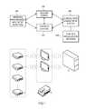
- FIG. 1illustrates a block diagram representing the basic components of an embodiment of the general systems for continuous and objective movement monitoring.
- FIG. 2illustrates a detailed diagram of the basic components and interconnections of an embodiment of the wearable apparatus for continuous and objective movement monitoring.
- FIG. 3illustrates a block diagram representing an embodiment of a wireless synchronization scheme based on a single master clock.
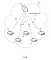
- FIG. 4illustrates a block diagram representing an embodiment of a wireless synchronization scheme based on mesh synchronization.
- FIG. 5illustrates a block diagram representing an embodiment of a wireless synchronization scheme based on mesh synchronization using the Flooding Time Synchronization Protocol (FTSP).
- FTSPFlooding Time Synchronization Protocol
- FIG. 6illustrates a block diagram representing the basic components of an embodiment of for robust wireless communications wireless systems.
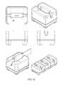
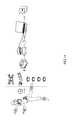
- FIG. 7illustrates a particular embodiment of the movement monitor, the docking station, and the docking mechanism.
- FIG. 8illustrates a second embodiment of the movement monitor, the docking station, and the docking mechanism, this embodiment particularly adapted to the wearable a wrist watch.
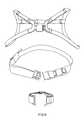
- FIG. 9illustrates embodiments of the movement monitor with sternum, waist, and wrist/ankle straps.
- FIG. 10illustrates an embodiment of the docking station and a connected docking station for simultaneously charging multiple movement monitors.
- FIG. 11illustrates an embodiment of the access point.
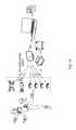
- FIG. 12illustrates a complete system comprise of a movement monitor, a docking station, and access point and a computer system for data analysis and visualization.
- FIG. 13illustrates an example comparing the use of the disclosed wireless synchronized wearable movement monitors and the closest related prior art.
- FIG. 14illustrates the use of the complete system according to one embodiment where wireless mesh synchronized data is collected during continuous ambulatory monitoring by the movement monitors and stored locally until the monitors are docketed and the docking station transfers the data to a computer system including analysis methods to visualize and produce reports of the results.
- FIG. 15illustrates the use of the complete system according to one embodiment where wireless master or mesh synchronized data is collected during continuous monitoring by the movement monitors and stored locally until the monitors are docketed and the docking station transfers the data to a computer system including analysis methods to visualize and produce reports of the results.
- FIG. 16illustrates the use of the complete system according to one embodiment where wireless mesh synchronized data is collected during continuous or objective monitoring by the movement monitors and such data is wirelessly streamed using robust wireless streaming to a computer system including analysis methods to visualize and produce reports of the results.
- the system for continuous ambulatory monitoring of movement disorderscomprises: one or more wearable devices (movement monitors) 100 , one or more docking stations 102 connected to a plurality of access points, one or more data servers 104 , and a plurality of statistical and signal processing analysis methods 106 to process the movement data collected by the wearable devices and generate a plurality movement metrics.
- FIG. 12illustrates a complete system comprise of a movement monitor, a docking station, and access point and a computer system for data analysis and visualization.
- FIG. 14-16illustrates several uses of the complete system.
- the wearable movement monitor 100is a lightweight device ( ⁇ 100 g) comprising (a) a sensor module comprising a plurality of low power ( ⁇ 50 mW) solid state and micro-electromechanical systems kinematics sensors; (b) a microprocessor module comprising a low power ( ⁇ 50 mW) microcontroller configured for device control, device status, and device communication; (c) a data storage module comprising a solid state local storage medium; (d) a wireless communication module comprising a low power ( ⁇ 50 mW) surface mount transceiver and an integrated antenna; and (e) a power and docking module comprising a battery, an energy charging regulator circuit, and a docking connector.
- a sensor modulecomprising a plurality of low power ( ⁇ 50 mW) solid state and micro-electromechanical systems kinematics sensors
- a microprocessor modulecomprising a low power ( ⁇ 50 mW) microcontroller configured for device control, device status, and device communication
- the micro-electromechanical systems kinematics sensorsinclude a plurality of solid-state, surface mount, low power, low noise inertial sensors including a plurality of accelerometers and gyroscopes, as well as a solid-state, surface mount, low power, low noise, Gigantic Magneto-Resistance (GMR) magnetometers.
- the solid state local storage mediumis substantially equivalent to a high capacity SD card (>4 GB) in order to enable for multi-day (>2 days) local storage of movement monitoring data at high frequencies (sampling frequencies>20 Hz).
- the communication moduleis designed to communicate with a plurality of wearable movement monitors (peer-to-peer communication) in order to synchronize the monitors, and to communicate with a host computer (peer-to-host communication) in order to transmit sensor data, uses a bidirectional groundplane PCB patch antenna, and accepts transmissions from a plurality of beacons to calculate the device location.
- peer-to-peer communicationwearable movement monitors
- host computerpeer-to-host communication
- the power and docking moduleincludes an external connector to access external power and provide high speed communication with an external docking station
- the energy charging regulator circuitis a solid state integrated circuit charger such as a linear Lithium Ion Polymer battery charger IC and said battery is a Lithium Ion Polymer battery
- Lithium Ion Polymer batterycan be selected for a particular application as a function of its mAHr characteristics (e.g. 450 mAHr or 50 mAHr).
- the wearable movement monitoring apparatus 100further comprises an external movement monitoring system comprising: (a) an external docking station for re-charging the wearable movement monitoring apparatus, storing movement data, and transmitting the movement data to a plurality of receiver devices, (b) a plurality of wireless transceiver access points for wireless transmission of the movement data to a plurality of receiver devices, and (c) a web-enabled server computer including a clinical data management and analysis system for storing, sharing, analyzing, and visualizing movement data using a plurality of statistical signal processing methods.
- an external movement monitoring systemcomprising: (a) an external docking station for re-charging the wearable movement monitoring apparatus, storing movement data, and transmitting the movement data to a plurality of receiver devices, (b) a plurality of wireless transceiver access points for wireless transmission of the movement data to a plurality of receiver devices, and (c) a web-enabled server computer including a clinical data management and analysis system for storing, sharing, analyzing, and visualizing movement data
- the movement monitor apparatus 100is a lightweight, low-power, low noise, wireless wearable device with the following characteristics: 1) weight of 22 g, 2) sampling frequency of 128 Hz, 3) wireless synchronization, 4) 14 bit resolution, 5) three-axis MEMS accelerometers (user configurable from ⁇ 2 g to ⁇ 6 g), 6) three-axis MEMS gyroscopes with a ⁇ 1500 deg/s range, 7) three-axis magnetometers with a ⁇ 6 Gauss range, 7) automatically calibrated, 8) over 16 hours of operation per charge, and 9) over 20 days of onboard storage capacity.
- the device 100includes solid state, low-power, low-noise sensors as follows: accelerometer (0.8 cm/s 2 /sqr(Hz)), XY gyroscope (0.05 deg/s/sqrt(Hz)), z Gyroscope (0.05 deg/s/sqrt(Hz)), and magnetometer (40 nT/sqrt(Hz)).
- the wearable devices or apparatus 100are compact movement monitoring devices that continuously record data from embedded sensors.
- the sensors 100may be worn at any convenient location on the body that can monitor impaired movement. Convenient locations include the wrists, ankles, trunk, and waist.
- the sensorsinclude one or more channels of electromyography, accelerometers, gyroscopes, magnetometers, and other MEMS sensors that can be used to monitor movement.
- the wearable sensors 100have sufficient memory and battery life to continuously record inertial data throughout the day from the moment subjects wake up until they go to sleep at night, typically 18 hours or more.
- the deviceuses a storage element substantially equivalent to an SD card to store movement data for extended periods of time (e.g. 1 month).
- the sensors 100automatically start recording when they are removed from the docking station. In one embodiment, there is no need for the user to turn them on or off.
- the wearable devices 100include the components and interconnections detailed in FIG. 2 : a sensor module 200 , a microprocessor module 210 , a data storage module 221 , a wireless communication module 230 , and a power and docking module 243 .
- a sensor module 200a microprocessor module 210 , a data storage module 221 , a wireless communication module 230 , and a power and docking module 243 .
- An embodiment of each of these modulescomprising the apparatus for continuous and objective monitoring of movement disorders is described in detail below.
- the embodiments disclosedcan be use to characterize movement in a plurality of application areas including continuous movement monitoring, activity monitoring, biomechanics, sports science, motion research, human movement analysis, orientation tracking, animation, virtual reality, ergonomics, and inertial guidance for navigation, robots and unmanned vehicles.
- FIG. 8illustrates a second embodiment of the movement monitor, the docking station, and the docking mechanism, this embodiment particularly adapted to the wearable a wrist watch.
- FIG. 9illustrates embodiments of the movement monitor with sternum, waist, and wrist/ankle straps.
- the sensor module 200 in FIG. 2contains the motion sensors necessary to characterize the symptoms of movement disorders.
- Three of these sensorsare low noise accelerometers 202 .
- the accelerometersare off-the-shelf, commercially available Micro-ElectroMechanical Systems (MEMS) acceleration sensors in small surface-mount packages, such as the STMicro LIS344AHL.
- MEMSMicro-ElectroMechanical Systems
- the acceleration sensorsare custom made MEMS accelerometers.
- the accelerometersare arranged in three orthogonal axes either on a single multi-axis device, or by using one or more separate sensors in different mounting configurations.
- the output of the accelerometers 202is an analog signal.
- This analog signalneeds to be filtered to remove high frequency components by anti-aliasing filters 206 , and then sampled by the analog-to-digital (ADC) peripheral inputs of the microprocessor 212 .
- the anti-aliasing filtersare single pole RC low-pass filters that require a high sampling frequency; in another, they are operational amplifiers with multiple-pole low pass filters that may use a slower sampling frequency.
- the deviceincludes an analog interface circuit (AIC) with a programmable anti-aliasing filter.
- the output of the accelerometersis digital, in which case the sensor must be configured for the correct gain and bandwidth and sampled at the appropriate rate to by the microprocessor 212 .
- the next three sensors in the sensor module 200are solid state, low noise rate gyroscopes 203 .
- the gryroscopesare off-the-shelf, commercially available Micro-ElectroMechanical Systems (MEMS) rotational sensors in small surface-mount packages, such as a the Invensense IDG-650 and the Epson Toyocomm XV-3500CBY. In other embodiments they are custom made MEMS.
- MEMSMicro-ElectroMechanical Systems
- the gyroscopesare arranged in three orthogonal axes either on a single multi-axis device, or by using one or more separate sensors in different mounting configurations.
- the output of the gyroscopes 203is an analog signal.
- This analog signalneeds to be filtered to remove high frequency components by anti-aliasing filters 207 , and then sampled by the analog-to-digital (ADC) peripheral inputs of the microprocessor 212 .
- the anti-aliasing filtersare single pole RC low-pass filters that require a high sampling frequency; in another, they are operational amplifiers with multiple-pole low pass filters that may use a slower sampling frequency.
- the deviceincludes an analog interface circuit (AIC) with a programmable anti-aliasing filter.
- the output of the gyroscopesis digital, in which case the sensor must be configured for the correct gain and bandwidth and sampled at the appropriate rate to by the microprocessor 212 .
- the sensor module 200also contains one or more aiding sensors.
- an aiding systemis a three axis magnetometer 201 .
- the magnetometerBy sensing the local magnetic field, the magnetometer is able to record the device's two axes of absolute attitude relative to the local magnetic field which can aid correcting drift in other inertial sensors such as the gyroscopes 203 .
- the magnetometer sensorsare off-the-shelf, low noise, solid-state, GMR magnetometer in small surface-mount packages such as the Honeywell HMC1043. In other embodiments they are custom made MEMS.
- the magnetometersare arranged in three orthogonal axes either on a single multi-axis device, or by using one or more separate sensors in different mounting configurations.
- each magnetometer 203is an analog signal from two GMR magnetometers arranged in a Wheatstone bridge configuration, which requires a differential operational amplifier 204 to amplify the signal and an anti-aliasing filter 207 to remove high frequency components. These amplified, anti-aliased filters are then sampled by the analog-to-digital (ADC) peripheral inputs of the microprocessor 212 .
- the anti-aliasing filtersare single pole RC low-pass filters that require a high sampling frequency; in another, they are operational amplifiers with multiple-pole low pass filters that may have a slower sampling frequency.
- the deviceincludes an analog interface circuit (AIC) with a programmable anti-aliasing filter.
- AICanalog interface circuit
- the output of the magnetometersis digital, in which case the sensor must be configured for the correct gain and bandwidth and sampled at the appropriate rate to by the microprocessor 212 .
- magnetometer sensorsmay need considerable support circuitry 208 , which in one embodiment include such functions as temperature compensation of the Wheatstone bridge through controlling the bridge current, and low frequency magnetic domain toggling to identify offsets through the use of pulsed set/reset coils.
- a Global Positioning System Satellite Receiveris added in order to give absolute geodetic position of the device.
- a barometric altimeteris added to give an absolute indication of the vertical altitude of the device.
- beaconsconsisting of devices using the same wireless transceiver 231 could also tag specific locations by recording the ID of the beacon.
- the microprocessor module 210 in FIG. 2is responsible for device control, device status, as well as local data and communication processing.
- the microprocessor 212may indicate the device's status on some kind of visual or auditory display 211 on the device.
- the displayis a a red-green-blue (RGB) light emitting diode (LED).
- RGBred-green-blue
- a small LCD panelis used to display information, such as the time of day, system status such as battery charge level and data storage level, and a medication reminder for subjects who require medication for to treat their movement disorder.
- the medication reminderis a gentle vibration, auditory, or visual cue that reminds subjects to take any necessary treatment or perform symptom measurement tasks.
- the microprocessor 212is a low power microcontroller such as the Texas Instruments MSP430FG4618.
- the microprocessorcoordinates the sampling of sensors, data processing, data storage, communications, and synchronization across multiple devices.
- the microprocessorshould be a lower power device with enough computational resources (e.g. 20 MIPS) and input/output resources (more than 20 general purpose input/output lines, 12 analog-to-digital converter inputs, and more than two serial communication ports) to interface to other modules.
- the microprocessoris clocked by a low drift time base 213 in order to accurately maintain both a real time clock (RTC) and to minimize drift in the synchronous sampling across multiple devices on one subject over long periods of time.
- the low drift time baseis a temperature compensated crystal oscillator (CTXO) such as the Epson TG3530SA.
- the time baseis a standard microprocessor crystal with custom temperature compensation using the digital-to-analog converter of the microprocessor 212 . Using a CTXO instead of a standard microprocessor crystal also minimizes power consumed by the wireless communication module 230 since the frequency necessary to re-synchronize devices is reduced.
- the data storage module 221stores the measurements from the sensors 200 and status of the device (such as the energy storage device's 245 charge level) locally on the device. It is especially designed to support studies involving multi-day continuous movement monitoring.
- the deviceis capable of storing movement data at a sampling frequency of 128 Hz for over 20 days.
- the local storageis flash memory soldered to the device's printed circuit board.
- a high capacity Flash cardsuch as a >4 GB MicroSD card, is used with a high speed synchronous serial port (SPI) from the microprocessor 212 to minimize wire complexity and to enable a standard protocol to hand off to a host computer as necessary.
- the data storage moduleis greatly reduced, or even unnecessary, because data is streamed directly off the device using the wireless communication module 230 .
- the wireless communication module 230allows the device to communicate to other devices (peer-to-peer), to a host computer (peer-to-host) and to listen to other data such as wireless beacons.
- the wireless communication moduleserves multiple functions: it broadcasts data from the device's inertial sensors 200 to a computer or other recording device, it synchronizes sampling rate across multiple devices through a sampling time synchronization protocol, and allows for configuring the devices behavior (i.e. mode of operation). Another use for the wireless communication module is to listen for transmissions from beacons which informs the device about its current location (e.g. bathroom, kitchen, car, workplace).
- the communication protocolis a industry standard protocol such as Bluetooth, ZigBEE, WiFi or substantially equivalent protocol.
- itis a custom communication protocol based on a physical layer transceiver chip.
- the wireless communication moduleconsists of a low power, 2.4 GHz surface mount wireless transceiver 231 , such as the Nordic Semiconductor nRF24L01+.
- the wireless transceiveruses a small on-board antenna 232 , such as a chip antenna like the gigaNOVA Mica antenna for both transmitting and receiving wireless communications.
- the antennais a groundplane PCB patch antenna.
- the wireless transceiver 231uses a high speed synchronous serial port, such as the serial peripheral interface (SPI), to communicate with the host microprocessor 212 .
- the wireless transceiveris built into the microprocessor as a peripheral.
- the wireless transceiveruses skin conduction to create a Personal Area Network (PAN) instead of a broadcast radio.
- PANPersonal Area Network
- Another embodimentuses light, such as infrared light, as a wireless communication system like the industry standard IRDA.
- the antenna 232would be an optical transceiver.
- the movement monitorincorporates a wireless synchronization scheme based on master synchronization.
- the master wireless synchronization schemea plurality of movement monitors on a wireless network with a plurality of access points receive the data generated by the wireless network.
- One of these access pointswhich is identified during configuration, becomes the master timing source for the entire network. All other access points are synchronized to the master.
- FIG. 3illustrates a block diagram representing an embodiment of a wireless synchronization scheme based on a single master clock.
- the access pointsare synchronized to the master using a cable to transmit a synchronization clock.
- the between-access point synchronization signalis sent over the wireless network between access points, possibly on a different wireless channel.
- the synchronization signalis sent from the master access point to the other access points via connection to a local host computer.
- the access point synchronization signalis used to precisely time the transmission of a synchronization data packet.
- This data packetis transmitted at the exact same time by all access points and is received by all wireless nodes.
- This synchronized packetin one embodiment, contains the counter value representing the time since the epoch for the master access point clock.
- the wireless nodesOn receipt of the synchronization data packet, the wireless nodes adjust their clock or primary timer based on their local time stamp of the reception of that packet.
- the nodesutilize a timer-based hardware capture (capture and compare) input pin to get a precise offset between the arrival of the synchronization packet and the device's local time. This offset can be used to measure the drift in the sensor node's clock and allow the node to either adjust its clock frequency directly via a voltage controlled oscillator, or allow it to periodically adjust a counter/timer to be used for sampling.
- a single access pointis chosen to be the master access point, and thus the master clock, for the entire wireless network.
- all access pointsare updated to the same 64 bit absolute time stamp.
- This access pointgenerates a precisely and deterministically timed clock signal using its PWM peripheral which is distributed to all other access points.
- each access pointOn receipt of the clock pulse, each access point enters a high priority interrupt which has a known, deterministic delay to execution. Then each access point executes a predetermined number of instructions to send a synchronization packet from the access points to the rest of the wireless sensor nodes.
- This synch packetincludes the absolute time.
- the radios on the wireless sensor nodesreceive the packet and assert an interrupt line.
- This interrupt lineis tied to a capture and compare peripheral pin, which takes a snapshot of the local timer in an interrupt.
- This snapshotallows the sensor node to reliably and deterministically find out when exactly the packet was sent according to its onboard time base. The sensor node takes this snapshot and compares it to what it should be, given a known synchronization packet rate. The difference is used in a simple software PLL to synchronize the local timer with the master access point clock.
- the advantage to the master synchronization schemeis that it allows the sensor nodes to quickly and easily come into synchronization with the network: it requires very little computation to adjust the local clocks on the nodes, and the isochronous rate of the synchronization packets can be adjusted based on the need for synchronization tolerance. The higher the rate, the less time there is for clock drift.
- FIG. 15illustrates the use of the complete system according to one embodiment where wireless master or mesh synchronized data is collected during continuous monitoring by the movement monitors and stored locally until the monitors are docketed and the docking station transfers the data to a computer system including analysis methods to visualize and produce reports of the results.
- the wireless synchronization schemeis comprised of a plurality of sensors on a wireless network with a plurality of access points to receive the data generated by the wireless network.
- FIG. 4illustrates a block diagram representing an embodiment of a wireless synchronization scheme based on mesh synchronization.
- Packet transmission and reception in the mesh synchronization schememust be deterministic.
- the sending and receiving of mesh synchronization packetsis tied to a transmit enable from a local hardware timer. The packets will be sent at the exact time according to the local clock, and on receiving the synchronization packets, the nodes will capture their local timer values to determine their relative offsets.
- FIG. 5illustrates a block diagram representing an embodiment of a wireless synchronization scheme based on mesh synchronization using the Flooding Time Synchronization Protocol (FTSP).
- FTSPFlooding Time Synchronization Protocol
- a single nodeis dynamically elected to maintain global time. All other nodes synchronize their clocks to that of this root node. Each node receives synchronization packets from the root node and uses them to build a linear regression model of offset and drift from the global time. Once synchronized, these nodes can broadcast synchronization packets for nodes which are out of range of the root node to use for synchronization.
- the FTSP protocoluses two-way messaging to do sender-receiver synchronization propagating out from a root node.
- the first step in the FTSP mesh synchronizationis to dynamically choose a root node. After waiting for the timeout period, ROOT-TIMEOUT, without receiving a synchronization packet each node will declare itself root and start sending out synchronization packets.
- ROOT-TIMEOUTwithout receiving a synchronization packet each node will declare itself root and start sending out synchronization packets.
- Upon receiving a synchronization packet from another nodeif that node's device ID is lower than a device that has declared itself root, it demotes itself to a normal node. In this way, the node with the lowest device ID will eventually be the only root node.
- the nodeEach time a synchronization packet is received, the node checks to see if it is a root. If it is a root, then it checks to see if its device ID is less than the packet's root ID. If the device ID is less, nothing happens and this node stays a root. If the device ID is greater, this node stops being a root, and uses the packet's root ID for any future synchronization packets it sends out.
- a regular nodereceives a synchronization packet, it calculates the difference between the packet's global time and the local time. This difference is shifted into a buffer for linear regression. If the regression buffer is full, the linear regression is calculated. The linear regression produces an offset and drift estimate.
- the deviceis now considered synchronized and can transmit its own synchronization packets with the root ID and the corrected local time whenever it gets a new packet.
- Each synchronization packetcontains the current global time according to the transmitter, the root device ID, and the synchronization packet count.
- the packet counteris incremented by the root every time a new packet is sent. When a regular node sends a packet it uses the most recent packet count it has received.
- the FTSPis modified such that each synchronized node broadcasts its estimated clock model parameters.
- the root nodecan then estimate it's own parameters such that the error of all the clocks from the nominal frequency is minimized. If the distribution of clock frequencies is centered about the nominal frequency, this will reduce drift with respect to actual time.
- the Reference Broadcast Protocolis used to synchronize the nodes. A root node is chosen to send synchronization packets. The other nodes then exchange their local times upon receipt of each synchronization packet.
- the Timing-sync Protocol for Sensor Networksis used.
- each node in the networkwill calculate confidence intervals for its own clock and provide this to other nodes for use in calculating the weight that its clock should provide to the statistical network time. In another embodiment, each node calculates the confidence interval for the other nodes based on the variance of received packet time compared to their local clock.
- nodesIn cases where a node or subset of nodes gets disconnected from the network, they will calculate their own network time using the nodes they can connect to. The larger the network, or the better their local clock, the more confident the unified network time can be. In the case where two or more groups are connected via a small subset of nodes the unified time can be propagated throughout the network. When two or more subsets of the network get completely disconnected from each other the chance for multiple diverging network times can occur. Reconnection of the two subnets is smoothly implemented by using the statistical modeling and allowing only very slow slewing of local clocks.
- FIG. 14illustrates the use of the complete system according to one embodiment where wireless mesh synchronized data is collected during continuous ambulatory monitoring by the movement monitors and stored locally until the monitors are docketed and the docking station transfers the data to a computer system including analysis methods to visualize and produce reports of the results.
- FIG. 6illustrates a block diagram representing the basic components of an embodiment of the general systems for robust wireless communications in small wireless systems including a data collection unit 600 , a data controller unit 602 , a data storage unit 608 , a radio 604 , and an antenna 606 .
- Disclosed embodimentsinclude a new apparatus for robust wireless communications for small wireless systems, such as a wearable movement monitor, comprising of (a) a small sized, large capacity, low power, nonvolatile data storage unit, (b) a low power wireless communication system, (c) a small antenna, (d) a data collection unit to collect data to be transmitted, (e) a data controller to control the flow and storage of data in the system, and (f) data controller means to control how the data is processed, stored and transmitted.
- the data storage unitis a small sized, large capacity, low power, nonvolatile data storage system. In one embodiment, and without limitation, it is a commercially available microSD card with 8 GB of data storage. In another embodiment, it is a large capacity Flash surface-mounted IC. In another embodiment, it is a large capacity SDRAM chip with battery backup.
- the low power radio unitis a small volume, extremely low power radio system. In one embodiment, it is a a Nordic Semiconductor nRF24L01+ 2.4 GHz transceiver. In another embodiment, it is a low power IC that conforms to a radio standard such as Bluetooth or IEEE 802.15 (ZigBee).
- the small antennais an extremely small volume antenna that trades a reduction in radiation efficiency for an decrease in the occupied volume by the antenna. In one embodiment, the antenna is a small custom made 2.4 GHz PCB patch antenna. In another embodiment, it is a commercially available chip antenna.
- the data collection unitcollects the data to be transmitted.
- the data collection unitis a six-degree-of-freedom inertial measurement unit (three axis accelerometers, three axis gyroscopes). In another embodiment, the data collection unit contains a six-degree-of-freedom inertial measurement unit (three axis accelerometers, three axis gyroscopes), a three axis magnetometer, and a temperature sensor.
- the data controllercontrols the flow of data from the data collection unit to the data storage unit, and from the data storage unit to the low power radio unit.
- the data controlleris a microcontroller such as the Texas Instruments MSP430FG4618, in another it is a programmable logic device like an FPGA or CPLD.
- the system and apparatusincludes a data transfer controller 602 that can run one of several methods, optimizing for power, communication bandwidth, or robustness.
- the data controller methods running on the data controllerstore all data from the data collection on the data storage unit, and stream the data from the data storage unit to the low power radio unit as the unreliable radio channel allows.
- the data controller methodfirst sends the data to the lower power radio unit, then stores only the data that has failed to successfully transmit.
- the data controller methodsstore data in the data storage unit while sensing that the state of the communication channel. If the channel is not available, the data controller methods shuts off the low power radio to save power, and continues to poll the channel until it is available.
- the data controller methodsstore the data in the data storage unit, and only occasionally turns on the radio into their full speed modes in order to quickly and efficiently “burst” the data from the device.
- the external data storage unitutilizes a single data bus with only half duplex reads and writes.
- the data controller methodsmust schedule and prioritize the data on the data bus.
- the radio unitit is therefore possible for the radio unit to be temporarily starved of data pending a read request since a pending read operation is only performed if there are no pending writes in the queue.
- the data controllerhas a “data latency bound” that enables the data controller methods to keep only so many seconds (or minutes, or hours) of data before discarding the data.
- FIG. 11illustrates an embodiment of the access point.
- FIG. 16illustrates the use of the complete system according to one embodiment where wireless mesh synchronized data is collected during continuous or objective monitoring by the movement monitors and such data is wirelessly streamed using robust wireless streaming to a computer system including analysis methods to visualize and produce reports of the results.
- the power and docking module 240provides external power, power regulation, and external data connections to the device.
- One aspect of the power and docking moduleis the docking connector 242 which provides an external connector to access external power and provide high speed communication with the docking station, and thus to a computer or other recording device.
- One embodiment of the connector 242is the Hirose ST60 series connector which provides enough connections for both power and complete hand off of the data storage module 220 for extremely high throughput downloading of data.
- the docking connectoris completely wireless, and provides inductive wireless power transmission for external power and a local high speed wireless data channel.
- the energy storage chargeris a linear Lithium Ion Polymer battery charger IC such as the Microchip MCP73833, or substantially equivalent integrated circuit. In another embodiment, it is a switching battery charge IC. In another embodiment, the microprocessor 212 measures the battery capacity and controls the energy storage device's charge directly.
- the energy storage mechanism 245is in one embodiment a Lithium Ion Polymer battery. Other embodiments involve other energy storage mechanism, such as super capacitors or other battery chemistries.
- the Lithium ion polymer batteryshould be sized appropriately to be as small as possible for the comfort of the subject wearing the device, yet still contain enough stored energy to power the system for a sufficiently long period of time.
- a 450 mAHr batteryis used to enable the device to last 24 hours and thus be usable for a full day before recharging is required.
- a smaller 50 mAHr batteryis used to minimize the device size for short term clinical use.
- a power regulator 243must be used to regulate the power coming from the energy storage device.
- a simple voltage regulatorsuch as the Texas Instruments TPS79901 or equivalent, prepares the energy storage device's power for use by the other modules ( 200 , 210 , 210 , 220 , 230 ).
- an energy harvesting device 241is a small solar panel on the outside of the device. Another is a small kinetic generator using piezoelectric materials to generate voltage. A third uses heat differences between the subject's skin and the ambient air temperature.
- the devicein order to facilitate use in the clinic, home, or other normal daily environments, the device includes a docking station 102 that is used to charge the batteries of the wearable devices 100 and download the data from each day of activities.
- the docking station 102uploads the data using whatever means is available in that setting. If high-speed Internet access is available within the home, this may be used for data upload. Alternatively it permits the user to download the data to a portable storage device such as a USB thumb drive or hard drive that can then be transported to a site for final upload to the data server. If there is no simple means to download the data from the docking station 102 , the data is downloaded once the docking station is returned at the end of the monitoring period.
- the docking station 102requires no user intervention.
- the devices 100stop recording as soon as they are docked and start recording as soon as they are undocked.
- the docking station 102does not include any buttons.
- the docking station 102can be connected to a computer for data extraction and processing.
- FIG. 7illustrates a particular embodiment of the movement monitor, the docking station, and the docking mechanism.
- FIG. 8illustrates a second embodiment of the movement monitor, the docking station, and the docking mechanism, this embodiment particularly adapted to the wearable a wrist watch.
- FIG. 10illustrates an embodiment of the docking station and a connected docking station for simultaneously charging multiple movement monitors.
- the server 104runs automatic statistical signal processing methods 106 to analyze the data and compute the results needed for the application.
- the systemprovides data for three applications: 1) human movement research, 2) movement disorders studies and clinical trials, and 3) clinical care.
- the systemprovides a simple means for researchers to conduct studies in human movement with wearable sensors 100 . Study participants have an easy means of handling the devices by simply docking them when not in use. researchers have easy, secure, and protected access to their raw sensor data through the server 104 .
- the systemalso provides full support for research studies and clinical trials in movement disorders such as Parkinson's disease and essential tremor.
- the systemprovides the ability to do sequential analysis for continuous monitoring of clinical studies.
- the systemhas strict, secure, and encrypted access to any protected health information that is stored in the server.
- the systemalso supports clinical monitoring of individual patients to determine their response to therapy. This is especially helpful for movement disorders such as advanced Parkinson's in which the degree of motor impairment fluctuates continuously throughout the day.
- the serverprovides secure, encrypted access to patient records for authenticated care providers as well as patients themselves.
- the algorithms 106process the raw device data and extract the metrics of interest. These algorithms are insensitive to normal voluntary activities, but provide sensitive measures of the motor impairments of interest. In Parkinson's disease this may include tremor, gait, balance, dyskinesia, bradykinesia, rigidity, and overall motor state.
- aspects of the disclosed embodimentsmay also be practiced in distributed computing environments where tasks are performed by remote processing devices that are linked through a communications network.
- program modulesmay be located in both local and remote storage media including memory storage devices.
Landscapes
- Health & Medical Sciences (AREA)
- Life Sciences & Earth Sciences (AREA)
- Engineering & Computer Science (AREA)
- Physics & Mathematics (AREA)
- Animal Behavior & Ethology (AREA)
- Public Health (AREA)
- Veterinary Medicine (AREA)
- General Health & Medical Sciences (AREA)
- Surgery (AREA)
- Molecular Biology (AREA)
- Medical Informatics (AREA)
- Biophysics (AREA)
- Pathology (AREA)
- Biomedical Technology (AREA)
- Heart & Thoracic Surgery (AREA)
- Computer Networks & Wireless Communication (AREA)
- Signal Processing (AREA)
- Physiology (AREA)
- Psychiatry (AREA)
- Computer Vision & Pattern Recognition (AREA)
- Artificial Intelligence (AREA)
- Mathematical Physics (AREA)
- Dentistry (AREA)
- Oral & Maxillofacial Surgery (AREA)
- Arrangements For Transmission Of Measured Signals (AREA)
- Measurement Of The Respiration, Hearing Ability, Form, And Blood Characteristics Of Living Organisms (AREA)
Abstract
Description
Claims (18)
Priority Applications (3)
| Application Number | Priority Date | Filing Date | Title |
|---|---|---|---|
| US13/037,310US8647287B2 (en) | 2008-12-07 | 2011-02-28 | Wireless synchronized movement monitoring apparatus and system |
| US13/920,032US20140066816A1 (en) | 2008-12-07 | 2013-06-17 | Method, apparatus, and system for characterizing gait |
| US14/146,157US10117204B2 (en) | 2008-12-07 | 2014-01-02 | Wireless synchronized apparatus and system |
Applications Claiming Priority (4)
| Application Number | Priority Date | Filing Date | Title |
|---|---|---|---|
| US12048508P | 2008-12-07 | 2008-12-07 | |
| US12/632,778US8920345B2 (en) | 2008-12-07 | 2009-12-07 | System and apparatus for continuous monitoring of movement disorders |
| US30876410P | 2010-02-26 | 2010-02-26 | |
| US13/037,310US8647287B2 (en) | 2008-12-07 | 2011-02-28 | Wireless synchronized movement monitoring apparatus and system |
Related Parent Applications (2)
| Application Number | Title | Priority Date | Filing Date |
|---|---|---|---|
| US12/632,778ContinuationUS8920345B2 (en) | 2008-12-07 | 2009-12-07 | System and apparatus for continuous monitoring of movement disorders |
| US12/632,778Continuation-In-PartUS8920345B2 (en) | 2008-12-07 | 2009-12-07 | System and apparatus for continuous monitoring of movement disorders |
Related Child Applications (2)
| Application Number | Title | Priority Date | Filing Date |
|---|---|---|---|
| US13/920,032ContinuationUS20140066816A1 (en) | 2008-12-07 | 2013-06-17 | Method, apparatus, and system for characterizing gait |
| US14/146,157ContinuationUS10117204B2 (en) | 2008-12-07 | 2014-01-02 | Wireless synchronized apparatus and system |
Publications (2)
| Publication Number | Publication Date |
|---|---|
| US20110214030A1 US20110214030A1 (en) | 2011-09-01 |
| US8647287B2true US8647287B2 (en) | 2014-02-11 |
Family
ID=44505960
Family Applications (3)
| Application Number | Title | Priority Date | Filing Date |
|---|---|---|---|
| US13/037,310ActiveUS8647287B2 (en) | 2008-12-07 | 2011-02-28 | Wireless synchronized movement monitoring apparatus and system |
| US13/920,032AbandonedUS20140066816A1 (en) | 2008-12-07 | 2013-06-17 | Method, apparatus, and system for characterizing gait |
| US14/146,157ActiveUS10117204B2 (en) | 2008-12-07 | 2014-01-02 | Wireless synchronized apparatus and system |
Family Applications After (2)
| Application Number | Title | Priority Date | Filing Date |
|---|---|---|---|
| US13/920,032AbandonedUS20140066816A1 (en) | 2008-12-07 | 2013-06-17 | Method, apparatus, and system for characterizing gait |
| US14/146,157ActiveUS10117204B2 (en) | 2008-12-07 | 2014-01-02 | Wireless synchronized apparatus and system |
Country Status (1)
| Country | Link |
|---|---|
| US (3) | US8647287B2 (en) |
Cited By (8)
| Publication number | Priority date | Publication date | Assignee | Title |
|---|---|---|---|---|
| US20140081179A1 (en)* | 2012-09-19 | 2014-03-20 | Martin Christopher Moore-Ede | Personal Fatigue Risk Management System And Method |
| US20140172759A1 (en)* | 2012-12-19 | 2014-06-19 | Robert Bosch Gmbh | Intelligent electronic monitoring system |
| US20140324135A1 (en)* | 2011-11-25 | 2014-10-30 | Cyden Limited | Skin treatment apparatus |
| US20150313519A1 (en)* | 2010-02-22 | 2015-11-05 | Covidien Lp | Motion energy harvesting with wireless sensors |
| US9450681B1 (en) | 2015-05-08 | 2016-09-20 | Sharp Laboratories Of America, Inc. | Method and system for wireless transmission of quaternions |
| US10117204B2 (en) | 2008-12-07 | 2018-10-30 | Apdm, Inc | Wireless synchronized apparatus and system |
| US10979993B2 (en) | 2016-05-25 | 2021-04-13 | Ge Aviation Systems Limited | Aircraft time synchronization system |
| US11551396B2 (en)* | 2015-09-21 | 2023-01-10 | TuringSense Inc. | Techniques for establishing biomechanical model through motion capture |
Families Citing this family (124)
| Publication number | Priority date | Publication date | Assignee | Title |
|---|---|---|---|---|
| US10241127B2 (en)* | 2009-07-30 | 2019-03-26 | Here Global B.V. | Method, apparatus and computer program product for collecting activity data via a removable apparatus |
| GB2496083B (en)* | 2010-08-29 | 2016-01-06 | Goldwing Design & Construction Pty Ltd | Method and apparatus for a metal detection system |
| US8738323B2 (en) | 2010-09-30 | 2014-05-27 | Fitbit, Inc. | Methods and systems for metrics analysis and interactive rendering, including events having combined activity and location information |
| US8744803B2 (en) | 2010-09-30 | 2014-06-03 | Fitbit, Inc. | Methods, systems and devices for activity tracking device data synchronization with computing devices |
| US9148483B1 (en) | 2010-09-30 | 2015-09-29 | Fitbit, Inc. | Tracking user physical activity with multiple devices |
| US11243093B2 (en) | 2010-09-30 | 2022-02-08 | Fitbit, Inc. | Methods, systems and devices for generating real-time activity data updates to display devices |
| US8694282B2 (en) | 2010-09-30 | 2014-04-08 | Fitbit, Inc. | Methods and systems for geo-location optimized tracking and updating for events having combined activity and location information |
| US8615377B1 (en) | 2010-09-30 | 2013-12-24 | Fitbit, Inc. | Methods and systems for processing social interactive data and sharing of tracked activity associated with locations |
| US9253168B2 (en) | 2012-04-26 | 2016-02-02 | Fitbit, Inc. | Secure pairing of devices via pairing facilitator-intermediary device |
| US8954290B2 (en) | 2010-09-30 | 2015-02-10 | Fitbit, Inc. | Motion-activated display of messages on an activity monitoring device |
| US8762101B2 (en) | 2010-09-30 | 2014-06-24 | Fitbit, Inc. | Methods and systems for identification of event data having combined activity and location information of portable monitoring devices |
| US8954291B2 (en) | 2010-09-30 | 2015-02-10 | Fitbit, Inc. | Alarm setting and interfacing with gesture contact interfacing controls |
| US8620617B2 (en) | 2010-09-30 | 2013-12-31 | Fitbit, Inc. | Methods and systems for interactive goal setting and recommender using events having combined activity and location information |
| US10004406B2 (en) | 2010-09-30 | 2018-06-26 | Fitbit, Inc. | Portable monitoring devices for processing applications and processing analysis of physiological conditions of a user associated with the portable monitoring device |
| US10983945B2 (en) | 2010-09-30 | 2021-04-20 | Fitbit, Inc. | Method of data synthesis |
| US8805646B2 (en) | 2010-09-30 | 2014-08-12 | Fitbit, Inc. | Methods, systems and devices for linking user devices to activity tracking devices |
| US8762102B2 (en) | 2010-09-30 | 2014-06-24 | Fitbit, Inc. | Methods and systems for generation and rendering interactive events having combined activity and location information |
| US9241635B2 (en) | 2010-09-30 | 2016-01-26 | Fitbit, Inc. | Portable monitoring devices for processing applications and processing analysis of physiological conditions of a user associated with the portable monitoring device |
| US9390427B2 (en) | 2010-09-30 | 2016-07-12 | Fitbit, Inc. | Methods, systems and devices for automatic linking of activity tracking devices to user devices |
| US8738321B2 (en) | 2010-09-30 | 2014-05-27 | Fitbit, Inc. | Methods and systems for classification of geographic locations for tracked activity |
| US8712724B2 (en) | 2010-09-30 | 2014-04-29 | Fitbit, Inc. | Calendar integration methods and systems for presentation of events having combined activity and location information |
| US9116220B2 (en)* | 2010-12-27 | 2015-08-25 | Microsoft Technology Licensing, Llc | Time synchronizing sensor continuous and state data signals between nodes across a network |
| US8738925B1 (en) | 2013-01-07 | 2014-05-27 | Fitbit, Inc. | Wireless portable biometric device syncing |
| US9352207B2 (en)* | 2012-01-19 | 2016-05-31 | Nike, Inc. | Action detection and activity classification |
| US9586137B2 (en)* | 2012-05-07 | 2017-03-07 | EMBODIFY ApS | Method and system for improving bodily dexterity |
| CN103488128B (en)* | 2012-06-12 | 2016-01-20 | 郑州华粮科技股份有限公司 | Based on the grain information monitoring remote monitoring system of internet |
| US9588582B2 (en) | 2013-09-17 | 2017-03-07 | Medibotics Llc | Motion recognition clothing (TM) with two different sets of tubes spanning a body joint |
| US20140180595A1 (en) | 2012-12-26 | 2014-06-26 | Fitbit, Inc. | Device state dependent user interface management |
| US9641239B2 (en) | 2012-06-22 | 2017-05-02 | Fitbit, Inc. | Adaptive data transfer using bluetooth |
| JP5743221B2 (en)* | 2012-06-29 | 2015-07-01 | カシオ計算機株式会社 | Wireless synchronization system, wireless device, sensor device, wireless synchronization method, and program |
| US9632981B2 (en)* | 2012-07-12 | 2017-04-25 | Vital Connect, Inc. | Calibration of a chest-mounted wireless sensor device for posture and activity detection |
| US9386932B2 (en)* | 2012-10-29 | 2016-07-12 | Microsoft Technology Licensing, Llc | Wearable personal information system |
| US20140198034A1 (en) | 2013-01-14 | 2014-07-17 | Thalmic Labs Inc. | Muscle interface device and method for interacting with content displayed on wearable head mounted displays |
| US9728059B2 (en) | 2013-01-15 | 2017-08-08 | Fitbit, Inc. | Sedentary period detection utilizing a wearable electronic device |
| US20140197963A1 (en) | 2013-01-15 | 2014-07-17 | Fitbit, Inc. | Portable monitoring devices and methods of operating the same |
| US9039614B2 (en) | 2013-01-15 | 2015-05-26 | Fitbit, Inc. | Methods, systems and devices for measuring fingertip heart rate |
| US20140257730A1 (en)* | 2013-03-11 | 2014-09-11 | Qualcomm Incorporated | Bandwidth and time delay matching for inertial sensors |
| ITRM20130251A1 (en)* | 2013-04-26 | 2014-10-27 | Ergotest Innovation As | SYSTEM FOR MONITORING PHYSICAL PERFORMANCE OF USERS |
| WO2014186370A1 (en) | 2013-05-13 | 2014-11-20 | Thalmic Labs Inc. | Systems, articles and methods for wearable electronic devices that accommodate different user forms |
| KR101820252B1 (en) | 2013-06-12 | 2018-01-18 | 나이키 이노베이트 씨.브이. | Wearable device assembly with ability to mitigate data loss due to component failure |
| US10373714B1 (en) | 2013-07-12 | 2019-08-06 | Vital Connect, Inc. | Determination of bed-time duration using wearable sensors |
| JP6308451B2 (en)* | 2013-07-17 | 2018-04-11 | 和田 淳 | Voice recorder system and voice recorder |
| US20150124566A1 (en) | 2013-10-04 | 2015-05-07 | Thalmic Labs Inc. | Systems, articles and methods for wearable electronic devices employing contact sensors |
| US11426123B2 (en)* | 2013-08-16 | 2022-08-30 | Meta Platforms Technologies, Llc | Systems, articles and methods for signal routing in wearable electronic devices that detect muscle activity of a user using a set of discrete and separately enclosed pod structures |
| US10188309B2 (en) | 2013-11-27 | 2019-01-29 | North Inc. | Systems, articles, and methods for electromyography sensors |
| US10042422B2 (en) | 2013-11-12 | 2018-08-07 | Thalmic Labs Inc. | Systems, articles, and methods for capacitive electromyography sensors |
| US11921471B2 (en) | 2013-08-16 | 2024-03-05 | Meta Platforms Technologies, Llc | Systems, articles, and methods for wearable devices having secondary power sources in links of a band for providing secondary power in addition to a primary power source |
| US9788789B2 (en) | 2013-08-30 | 2017-10-17 | Thalmic Labs Inc. | Systems, articles, and methods for stretchable printed circuit boards |
| US8944958B1 (en) | 2013-10-02 | 2015-02-03 | Fitbit, Inc. | Biometric sensing device having adaptive data threshold and a performance goal |
| WO2015057623A2 (en) | 2013-10-14 | 2015-04-23 | Nike Innovate C.V. | Fitness training system for merging energy expenditure calculations from multiple devices |
| US20150147734A1 (en)* | 2013-11-25 | 2015-05-28 | International Business Machines Corporation | Movement assessor |
| US11039760B2 (en) | 2014-01-30 | 2021-06-22 | Koninklijke Philips N.V. | Detection of walking in measurements of the movement of a user |
| US11990019B2 (en) | 2014-02-27 | 2024-05-21 | Fitbit, Inc. | Notifications on a user device based on activity detected by an activity monitoring device |
| US9031812B2 (en) | 2014-02-27 | 2015-05-12 | Fitbit, Inc. | Notifications on a user device based on activity detected by an activity monitoring device |
| US10199008B2 (en) | 2014-03-27 | 2019-02-05 | North Inc. | Systems, devices, and methods for wearable electronic devices as state machines |
| CN104939835B (en)* | 2014-03-31 | 2018-07-10 | 日本电气株式会社 | Walk angle measuring method and device |
| US9880632B2 (en) | 2014-06-19 | 2018-01-30 | Thalmic Labs Inc. | Systems, devices, and methods for gesture identification |
| HK1203120A2 (en)* | 2014-08-26 | 2015-10-16 | Well Being Digital Limited | A gait monitor and a method of monitoring the gait of a person |
| WO2016036554A1 (en)* | 2014-09-03 | 2016-03-10 | Smiths Medical Asd, Inc. | Medical device association systems and methods |
| US20170048731A1 (en)* | 2014-09-26 | 2017-02-16 | Hewlett Packard Enterprise Development Lp | Computing nodes |
| US10180340B2 (en)* | 2014-10-09 | 2019-01-15 | Invensense, Inc. | System and method for MEMS sensor system synchronization |
| KR20160044811A (en)* | 2014-10-16 | 2016-04-26 | 삼성전자주식회사 | Wearable sensor to monitor bio signal and method to monitor bio signal using wearable device |
| US9807221B2 (en) | 2014-11-28 | 2017-10-31 | Thalmic Labs Inc. | Systems, devices, and methods effected in response to establishing and/or terminating a physical communications link |
| JP6297752B2 (en)* | 2014-12-18 | 2018-03-20 | コーニンクレッカ フィリップス エヌ ヴェKoninklijke Philips N.V. | Activity classification and communication system for wearable medical devices |
| JP6689877B2 (en)* | 2015-03-27 | 2020-04-28 | インテル コーポレイション | Motion tracking using electronic devices |
| US10078435B2 (en) | 2015-04-24 | 2018-09-18 | Thalmic Labs Inc. | Systems, methods, and computer program products for interacting with electronically displayed presentation materials |
| US9936451B2 (en) | 2015-06-18 | 2018-04-03 | Samsung Electronics Co., Ltd. | Communication system for sensor networks |
| CN106705989B (en)* | 2015-07-21 | 2019-12-17 | 华为终端有限公司 | step recording method, device and terminal |
| JP6660110B2 (en)* | 2015-07-23 | 2020-03-04 | 原田電子工業株式会社 | Gait analysis method and gait analysis system |
| US9579025B1 (en)* | 2015-08-14 | 2017-02-28 | The United States Of America, As Represented By The Secretary Of The Navy | Timestamp-free synchronization for wireless body area networks |
| US11030918B2 (en)* | 2015-09-10 | 2021-06-08 | Kinetic Telemetry, LLC | Identification and analysis of movement using sensor devices |
| JP2019510388A (en)* | 2015-12-22 | 2019-04-11 | コーニンクレッカ フィリップス エヌ ヴェKoninklijke Philips N.V. | MEDICAL BODY AREA NETWORK, METHOD USING MBAN, AND STORAGE MEDIUM |
| US10341413B2 (en)* | 2016-01-04 | 2019-07-02 | Hangzhou Yameilijia Technology Co., Ltd. | Method and system for synchronizing robot with server |
| US10678337B2 (en)* | 2016-01-04 | 2020-06-09 | The Texas A&M University System | Context aware movement recognition system |
| EP3403206B1 (en)* | 2016-01-08 | 2025-08-06 | Nymbl Science, Inc. | Balance testing and training system |
| US10692011B2 (en) | 2016-01-21 | 2020-06-23 | Verily Life Sciences Llc | Adaptive model-based system to automatically quantify fall risk |
| WO2018137016A1 (en)* | 2016-01-25 | 2018-08-02 | B-Temia Inc. | Gait profiler system and method |
| US20170227470A1 (en)* | 2016-02-04 | 2017-08-10 | Proxy Technologies, Inc. | Autonomous vehicle, system and method for structural object assessment and manufacture thereof |
| US10080530B2 (en) | 2016-02-19 | 2018-09-25 | Fitbit, Inc. | Periodic inactivity alerts and achievement messages |
| JP6658077B2 (en)* | 2016-02-25 | 2020-03-04 | 花王株式会社 | How to assess stumbling risk |
| US10579169B2 (en)* | 2016-03-08 | 2020-03-03 | Egalax_Empia Technology Inc. | Stylus and touch control apparatus for detecting tilt angle of stylus and control method thereof |
| US10716495B1 (en)* | 2016-03-11 | 2020-07-21 | Fortify Technologies, LLC | Accelerometer-based gait analysis |
| US10990174B2 (en) | 2016-07-25 | 2021-04-27 | Facebook Technologies, Llc | Methods and apparatus for predicting musculo-skeletal position information using wearable autonomous sensors |
| US11216069B2 (en) | 2018-05-08 | 2022-01-04 | Facebook Technologies, Llc | Systems and methods for improved speech recognition using neuromuscular information |
| US11258312B2 (en)* | 2016-08-08 | 2022-02-22 | Bigmotion Technologies Inc. | Systems and methods for wireless charging |
| US11497966B2 (en)* | 2016-08-09 | 2022-11-15 | Beflex Inc. | Automatic coaching system and method for coaching user's exercise |
| US20180177436A1 (en)* | 2016-12-22 | 2018-06-28 | Lumo BodyTech, Inc | System and method for remote monitoring for elderly fall prediction, detection, and prevention |
| CN107122704A (en)* | 2017-03-16 | 2017-09-01 | 华南理工大学 | A kind of gait recognition method based on motion sensor |
| US11015954B2 (en)* | 2017-10-16 | 2021-05-25 | Uti Limited Partnership | Step detection using IMU and magnetometer data fusion |
| WO2019079757A1 (en) | 2017-10-19 | 2019-04-25 | Ctrl-Labs Corporation | Systems and methods for identifying biological structures associated with neuromuscular source signals |
| CN108112069B (en)* | 2017-12-19 | 2020-08-04 | 安科讯(福建)科技有限公司 | Method and system for maintaining synchronization of TDD-L TE equipment |
| US11150730B1 (en) | 2019-04-30 | 2021-10-19 | Facebook Technologies, Llc | Devices, systems, and methods for controlling computing devices via neuromuscular signals of users |
| US11961494B1 (en) | 2019-03-29 | 2024-04-16 | Meta Platforms Technologies, Llc | Electromagnetic interference reduction in extended reality environments |
| US10937414B2 (en) | 2018-05-08 | 2021-03-02 | Facebook Technologies, Llc | Systems and methods for text input using neuromuscular information |
| US11481030B2 (en) | 2019-03-29 | 2022-10-25 | Meta Platforms Technologies, Llc | Methods and apparatus for gesture detection and classification |
| US11907423B2 (en) | 2019-11-25 | 2024-02-20 | Meta Platforms Technologies, Llc | Systems and methods for contextualized interactions with an environment |
| US11493993B2 (en) | 2019-09-04 | 2022-11-08 | Meta Platforms Technologies, Llc | Systems, methods, and interfaces for performing inputs based on neuromuscular control |
| US11567573B2 (en) | 2018-09-20 | 2023-01-31 | Meta Platforms Technologies, Llc | Neuromuscular text entry, writing and drawing in augmented reality systems |
| US11908581B2 (en) | 2018-04-10 | 2024-02-20 | Hill-Rom Services, Inc. | Patient risk assessment based on data from multiple sources in a healthcare facility |
| US11504071B2 (en) | 2018-04-10 | 2022-11-22 | Hill-Rom Services, Inc. | Patient risk assessment based on data from multiple sources in a healthcare facility |
| EP3781018B1 (en)* | 2018-04-14 | 2025-06-18 | Y Michael Lee | System and method for monitoring and treating head, spine and body health and wellness |
| US10592001B2 (en) | 2018-05-08 | 2020-03-17 | Facebook Technologies, Llc | Systems and methods for improved speech recognition using neuromuscular information |
| WO2020047429A1 (en) | 2018-08-31 | 2020-03-05 | Ctrl-Labs Corporation | Camera-guided interpretation of neuromuscular signals |
| US11218981B2 (en)* | 2018-09-20 | 2022-01-04 | Kabushiki Kaisha Toshiba | Wireless mesh network and data transmission method |
| JP2020072334A (en)* | 2018-10-30 | 2020-05-07 | セイコーエプソン株式会社 | Sensor data processing system and sensor data synchronization system |
| US11694096B2 (en)* | 2018-11-13 | 2023-07-04 | Aetrex, Inc. | Foot differentiation scoring |
| EP3886693A4 (en) | 2018-11-27 | 2022-06-08 | Facebook Technologies, LLC. | Methods and apparatus for autocalibration of a wearable electrode sensor system |
| EA202191449A1 (en)* | 2018-12-14 | 2022-02-10 | Пд Нейротекнолоджи Лтд | CONTROL SYSTEM FOR MULTIPLE SYMPTOMS OF PARKINSON'S DISEASE AND THEIR INTENSITY |
| US11644314B2 (en)* | 2019-03-28 | 2023-05-09 | Phasorlab, Inc. | Synthetic mega gyroscope |
| JP7124965B2 (en)* | 2019-05-29 | 2022-08-24 | 日本電気株式会社 | Information processing device, walking environment determination device, walking environment determination system, information processing method, and storage medium |
| CN110558990B (en)* | 2019-07-30 | 2022-04-12 | 福建省万物智联科技有限公司 | Gait analysis method and device |
| WO2021055443A1 (en)* | 2019-09-17 | 2021-03-25 | Hoffmann-La Roche Inc. | Improvements in personalized healthcare for patients with movement disorders |
| US12370663B2 (en)* | 2019-09-20 | 2025-07-29 | Arcelormittal | Method for operating a hand-guided machine tool, and hand-held machine tool |
| TWI722590B (en)* | 2019-10-02 | 2021-03-21 | 瑞昱半導體股份有限公司 | Method of adjusting target clock and a wireless device thereof |
| CN110881214A (en)* | 2019-11-19 | 2020-03-13 | 天津大学 | A Time Synchronization Method for Wireless Sensor Networks |
| US11690564B2 (en) | 2019-11-22 | 2023-07-04 | MyFitnessPal, Inc. | Training plans and workout coaching for activity tracking system |
| US11517790B2 (en)* | 2019-11-26 | 2022-12-06 | MyFitnessPal, Inc. | Methods and apparatus for training plan delivery and logging |
| CN111012358B (en)* | 2019-12-26 | 2023-02-10 | 浙江福祉科创有限公司 | Human ankle joint motion trajectory measurement method and wearable device |
| US11463973B2 (en)* | 2020-04-28 | 2022-10-04 | Microsoft Technology Licensing, Llc | Clock synchronization using wireless side channel |
| US11665507B2 (en)* | 2020-09-15 | 2023-05-30 | Bi Incorporated | Systems and methods for intercept directing in a monitoring system |
| WO2022066093A1 (en)* | 2020-09-25 | 2022-03-31 | Walkbeat Ab | System and method for analyzing gait-related health and performance of an equine animal |
| US11868531B1 (en) | 2021-04-08 | 2024-01-09 | Meta Platforms Technologies, Llc | Wearable device providing for thumb-to-finger-based input gestures detected based on neuromuscular signals, and systems and methods of use thereof |
| US20230165484A1 (en)* | 2021-11-23 | 2023-06-01 | Orpyx Medical Technologies Inc. | System and method for analyzing force sensor data |
| WO2023183537A1 (en)* | 2022-03-23 | 2023-09-28 | Xeed, Llc | Low-power near-beam wireless inductive charging hub |
Citations (26)
| Publication number | Priority date | Publication date | Assignee | Title |
|---|---|---|---|---|
| US4117834A (en)* | 1976-12-02 | 1978-10-03 | Mc Partland Richard J | Physiological motor activity monitoring apparatus |
| US4306291A (en)* | 1979-03-27 | 1981-12-15 | Alcoholism & Drug Addiction Research Foundation | Tremor measurement device |
| US4353375A (en)* | 1977-04-26 | 1982-10-12 | The United States Of America As Represented By The Department Of Health & Human Services | Activity monitor for ambulatory subjects |
| DE4117834A1 (en)* | 1991-05-29 | 1992-12-03 | Steb Stahl Technologie Und Eng | Scrap pre-heating process for discontinuous steel-making processes - using waste gas from melting unit in scrap preheater with combustion chamber and intermittent fuel injection |
| US5293879A (en)* | 1991-09-23 | 1994-03-15 | Vitatron Medical, B.V. | System an method for detecting tremors such as those which result from parkinson's disease |
| DE4306291A1 (en)* | 1993-03-01 | 1994-09-08 | Gerhard P Hirsch | Discharge checking balance for the fully automatic weighing out of parts |
| US5562104A (en)* | 1994-04-01 | 1996-10-08 | Movemap, Inc. | Measuring movement disorder |
| US20020109621A1 (en)* | 2000-04-18 | 2002-08-15 | Motorola, Inc. | Wireless system protocol for telemetry monitoring |
| US20040015103A1 (en)* | 2000-10-05 | 2004-01-22 | Kamiar Aminian | Body movement monitoring system and method |
| US20050010139A1 (en)* | 2002-02-07 | 2005-01-13 | Kamiar Aminian | Body movement monitoring device |
| US20050234309A1 (en)* | 2004-01-07 | 2005-10-20 | David Klapper | Method and apparatus for classification of movement states in Parkinson's disease |
| US7089148B1 (en)* | 2000-10-30 | 2006-08-08 | The United States Of America As Represented By The Secretary Of The Navy | Method and apparatus for motion tracking of an articulated rigid body |
| US20070032748A1 (en)* | 2005-07-28 | 2007-02-08 | 608442 Bc Ltd. | System for detecting and analyzing body motion |
| US7210240B2 (en)* | 2001-02-23 | 2007-05-01 | Microstrain, Inc. | Posture and body movement measuring system |
| US20070249968A1 (en)* | 2004-03-16 | 2007-10-25 | Medtronic, Inc. | Collecting posture information to evaluate therapy |
| US20070255118A1 (en)* | 2004-04-14 | 2007-11-01 | Medtronic, Inc. | Collecting posture and activity information to evaluate therapy |
| US20080053253A1 (en)* | 2006-09-06 | 2008-03-06 | Individual Monitoring Systems, Inc | Fully ambulatory, self-contained gait monitor |
| US20080154098A1 (en)* | 2006-12-20 | 2008-06-26 | Margaret Morris | Apparatus for monitoring physiological, activity, and environmental data |
| US7395181B2 (en)* | 1998-04-17 | 2008-07-01 | Massachusetts Institute Of Technology | Motion tracking system |
| US20080284650A1 (en)* | 2007-05-18 | 2008-11-20 | Mnt Innovations Pty Ltd | Sports Sensor |
| US20080285805A1 (en)* | 2007-03-15 | 2008-11-20 | Xsens Technologies B.V. | Motion Tracking System |
| US20090281830A1 (en)* | 2008-05-07 | 2009-11-12 | Apdm, Inc | Collaboration marketplace platform system for research and management of chronic conditions |
| US20100030119A1 (en)* | 2008-07-29 | 2010-02-04 | Apdm, Inc | Method and apparatus for continuous measurement of motor symptoms in parkinson's disease and essential tremor with wearable sensors |
| US20100076348A1 (en)* | 2008-09-23 | 2010-03-25 | Apdm, Inc | Complete integrated system for continuous monitoring and analysis of movement disorders |
| USD614979S1 (en)* | 2009-07-07 | 2010-05-04 | Apdm, Inc | Personal inertial monitor |
| US20100145236A1 (en)* | 2008-12-07 | 2010-06-10 | Apdm, Inc. | System and Apparatus for Continuous Monitoring of Movement Disorders |
Family Cites Families (61)
| Publication number | Priority date | Publication date | Assignee | Title |
|---|---|---|---|---|
| US8280682B2 (en) | 2000-12-15 | 2012-10-02 | Tvipr, Llc | Device for monitoring movement of shipped goods |
| CA2218242C (en)* | 1996-10-11 | 2005-12-06 | Kenneth R. Fyfe | Motion analysis system |
| US5976083A (en) | 1997-07-30 | 1999-11-02 | Living Systems, Inc. | Portable aerobic fitness monitor for walking and running |
| DE29719250U1 (en) | 1997-10-30 | 1998-05-07 | Hauptverband der gewerblichen Berufsgenossenschaften eV, 53757 Sankt Augustin | Body stress measurement and analysis system |
| US6115681A (en)* | 1997-12-17 | 2000-09-05 | The United States Of America As Represented By The Secretary Of The Navy | Real-time data acquisition |
| US20060122474A1 (en) | 2000-06-16 | 2006-06-08 | Bodymedia, Inc. | Apparatus for monitoring health, wellness and fitness |
| US6804169B2 (en) | 2001-06-07 | 2004-10-12 | Honeywell International Inc. | Security system with portable timepiece and methods for use therewith |
| US6997882B1 (en) | 2001-12-21 | 2006-02-14 | Barron Associates, Inc. | 6-DOF subject-monitoring device and method |
| US6977868B2 (en) | 2002-02-14 | 2005-12-20 | Fossil, Inc | Method and apparatus for synchronizing data between a watch and external digital device |
| US9107615B2 (en) | 2002-12-18 | 2015-08-18 | Active Protective Technologies, Inc. | Method and apparatus for body impact protection |
| US7098148B2 (en)* | 2003-06-10 | 2006-08-29 | S.O.I.Tec Silicon On Insulator Technologies S.A. | Method for heat treating a semiconductor wafer |
| US7394385B2 (en) | 2003-07-31 | 2008-07-01 | Wellcare Systems, Inc. | Comprehensive monitoring system |
| CA2578653A1 (en) | 2004-07-29 | 2006-02-09 | Kevin Ferguson | A human movement measurement system |
| US7616110B2 (en) | 2005-03-11 | 2009-11-10 | Aframe Digital, Inc. | Mobile wireless customizable health and condition monitor |
| US7420472B2 (en) | 2005-10-16 | 2008-09-02 | Bao Tran | Patient monitoring apparatus |
| US7978081B2 (en)* | 2006-01-09 | 2011-07-12 | Applied Technology Holdings, Inc. | Apparatus, systems, and methods for communicating biometric and biomechanical information |
| US8055469B2 (en)* | 2006-03-03 | 2011-11-08 | Garmin Switzerland Gmbh | Method and apparatus for determining the attachment position of a motion sensing apparatus |
| US7558157B1 (en) | 2006-04-26 | 2009-07-07 | Itt Manufacturing Enterprises, Inc. | Sensor synchronization using embedded atomic clocks |
| US7912537B2 (en) | 2006-04-27 | 2011-03-22 | Medtronic, Inc. | Telemetry-synchronized physiological monitoring and therapy delivery systems |
| US7558622B2 (en) | 2006-05-24 | 2009-07-07 | Bao Tran | Mesh network stroke monitoring appliance |
| US7539533B2 (en) | 2006-05-16 | 2009-05-26 | Bao Tran | Mesh network monitoring appliance |
| EP2028931B1 (en) | 2006-05-16 | 2017-12-13 | Gmax Technology Ltd | Method and apparatus for real time performance assessment |
| JP2008003338A (en)* | 2006-06-23 | 2008-01-10 | Hitachi Ltd | Data processing apparatus and data processing program |
| US8217795B2 (en) | 2006-12-05 | 2012-07-10 | John Carlton-Foss | Method and system for fall detection |
| US7843325B2 (en)* | 2007-01-10 | 2010-11-30 | Halo Monitoring, Inc. | Wireless sensor network context data delivery system and method |
| US7628074B2 (en) | 2007-03-15 | 2009-12-08 | Mitsubishi Electric Research Laboratories, Inc. | System and method for motion capture in natural environments |
| US8900153B2 (en) | 2007-03-20 | 2014-12-02 | Mortara Instrument, Inc. | Ambulatory patient monitoring apparatus, system and method |
| US20090076419A1 (en)* | 2007-05-23 | 2009-03-19 | Cybernet Systems Corporation | Loss-of-balance and fall detection system |
| US8120498B2 (en)* | 2007-09-24 | 2012-02-21 | Intel-Ge Care Innovations Llc | Capturing body movement related to a fixed coordinate system |
| US8050881B1 (en)* | 2007-10-18 | 2011-11-01 | Enbiomedic | Post data-collection synchronization for approximation of simultaneous data |
| US7995467B2 (en)* | 2007-12-12 | 2011-08-09 | Synapsense Corporation | Apparatus and method for adapting to failures in gateway devices in mesh networks |
| US8112281B2 (en)* | 2007-12-19 | 2012-02-07 | Enbiomedic | Accelerometer-based control of wearable audio recorders |
| US7684954B2 (en) | 2007-12-31 | 2010-03-23 | Intel Corporation | Apparatus and method for classification of physical orientation |
| US20090184871A1 (en)* | 2008-01-23 | 2009-07-23 | Mostafa Tofighbakhsh | GPS with time integrated call initiation |
| US8382667B2 (en) | 2010-10-01 | 2013-02-26 | Flint Hills Scientific, Llc | Detecting, quantifying, and/or classifying seizures using multimodal data |
| EP2255582B1 (en)* | 2008-03-11 | 2011-11-30 | Philips Intellectual Property & Standards GmbH | Time synchronization of a plurality of different wireless networks with data sensors |
| US8773269B2 (en) | 2008-06-27 | 2014-07-08 | Neal T. RICHARDSON | Autonomous fall monitor |
| US8187182B2 (en) | 2008-08-29 | 2012-05-29 | Dp Technologies, Inc. | Sensor fusion for activity identification |
| US8926445B2 (en) | 2011-09-03 | 2015-01-06 | Golf Impact, Llc | Golf free swing measurement and analysis system |
| GB0820874D0 (en) | 2008-11-14 | 2008-12-24 | Europ Technology For Business | Assessment of gait |
| US8647287B2 (en) | 2008-12-07 | 2014-02-11 | Andrew Greenberg | Wireless synchronized movement monitoring apparatus and system |
| US8444564B2 (en) | 2009-02-02 | 2013-05-21 | Jointvue, Llc | Noninvasive diagnostic system |
| US8152694B2 (en) | 2009-03-16 | 2012-04-10 | Robert Bosch Gmbh | Activity monitoring device and method |
| US10973414B2 (en) | 2009-05-20 | 2021-04-13 | Sotera Wireless, Inc. | Vital sign monitoring system featuring 3 accelerometers |
| EP3533424B1 (en) | 2009-06-05 | 2024-10-02 | Advanced Brain Monitoring, Inc. | Wearable device for controlling position and provide feedbck to the user |
| TWI455705B (en) | 2009-10-07 | 2014-10-11 | Ind Tech Res Inst | Method and system for monioring sport related fitness by estimating muscle power and joint force of limbs |
| WO2011026257A1 (en) | 2009-09-03 | 2011-03-10 | Yang Changming | System and method for analyzing gait by fabric sensors |
| US8909497B1 (en) | 2010-04-06 | 2014-12-09 | Keynetik, Inc. | System and method for fall detection |
| WO2011163367A1 (en) | 2010-06-22 | 2011-12-29 | Mcgregor Stephen J | Method of monitoring human body movement |
| EP2593009B1 (en) | 2010-07-14 | 2020-08-26 | Ecole Polytechnique Federale De Lausanne (Epfl) | System and method for 3d gait assessment |
| US8744803B2 (en) | 2010-09-30 | 2014-06-03 | Fitbit, Inc. | Methods, systems and devices for activity tracking device data synchronization with computing devices |
| US8548740B2 (en) | 2010-10-07 | 2013-10-01 | Honeywell International Inc. | System and method for wavelet-based gait classification |
| US10049595B1 (en) | 2011-03-18 | 2018-08-14 | Thomas C. Chuang | Athletic performance and technique monitoring |
| US8738925B1 (en) | 2013-01-07 | 2014-05-27 | Fitbit, Inc. | Wireless portable biometric device syncing |
| US9282897B2 (en) | 2012-02-13 | 2016-03-15 | MedHab, LLC | Belt-mounted movement sensor system |
| US8849387B2 (en) | 2012-05-30 | 2014-09-30 | Mayo Foundation For Medical Education And Research | Low-power, compact, resilient system and method for physiological monitoring |
| US8996110B2 (en) | 2012-06-29 | 2015-03-31 | Pacesetter, Inc. | System and method for determining cause of irregularity within physiologic data |
| EP2895067B1 (en) | 2012-09-11 | 2021-02-24 | The Cleveland Clinic Foundation | Evaluation of movement disorders |
| US9060682B2 (en) | 2012-10-25 | 2015-06-23 | Alpinereplay, Inc. | Distributed systems and methods to measure and process sport motions |
| US9226706B2 (en) | 2012-12-19 | 2016-01-05 | Alert Core, Inc. | System, apparatus, and method for promoting usage of core muscles and other applications |
| US9393460B1 (en) | 2013-01-03 | 2016-07-19 | Aaron Emigh | Intelligent personal fitness device |
- 2011
- 2011-02-28USUS13/037,310patent/US8647287B2/enactiveActive
- 2013
- 2013-06-17USUS13/920,032patent/US20140066816A1/ennot_activeAbandoned
- 2014
- 2014-01-02USUS14/146,157patent/US10117204B2/enactiveActive
Patent Citations (27)
| Publication number | Priority date | Publication date | Assignee | Title |
|---|---|---|---|---|
| US4117834A (en)* | 1976-12-02 | 1978-10-03 | Mc Partland Richard J | Physiological motor activity monitoring apparatus |
| US4353375A (en)* | 1977-04-26 | 1982-10-12 | The United States Of America As Represented By The Department Of Health & Human Services | Activity monitor for ambulatory subjects |
| US4306291A (en)* | 1979-03-27 | 1981-12-15 | Alcoholism & Drug Addiction Research Foundation | Tremor measurement device |
| DE4117834A1 (en)* | 1991-05-29 | 1992-12-03 | Steb Stahl Technologie Und Eng | Scrap pre-heating process for discontinuous steel-making processes - using waste gas from melting unit in scrap preheater with combustion chamber and intermittent fuel injection |
| US5293879A (en)* | 1991-09-23 | 1994-03-15 | Vitatron Medical, B.V. | System an method for detecting tremors such as those which result from parkinson's disease |
| DE4306291A1 (en)* | 1993-03-01 | 1994-09-08 | Gerhard P Hirsch | Discharge checking balance for the fully automatic weighing out of parts |
| US5562104A (en)* | 1994-04-01 | 1996-10-08 | Movemap, Inc. | Measuring movement disorder |
| US7395181B2 (en)* | 1998-04-17 | 2008-07-01 | Massachusetts Institute Of Technology | Motion tracking system |
| US20020109621A1 (en)* | 2000-04-18 | 2002-08-15 | Motorola, Inc. | Wireless system protocol for telemetry monitoring |
| US7141026B2 (en)* | 2000-10-05 | 2006-11-28 | Ecole Polytechnique Federale de Lausanne/ Service des Relations Industrielles (SRI) | Body movement monitoring system and method |
| US20040015103A1 (en)* | 2000-10-05 | 2004-01-22 | Kamiar Aminian | Body movement monitoring system and method |
| US7089148B1 (en)* | 2000-10-30 | 2006-08-08 | The United States Of America As Represented By The Secretary Of The Navy | Method and apparatus for motion tracking of an articulated rigid body |
| US7210240B2 (en)* | 2001-02-23 | 2007-05-01 | Microstrain, Inc. | Posture and body movement measuring system |
| US20050010139A1 (en)* | 2002-02-07 | 2005-01-13 | Kamiar Aminian | Body movement monitoring device |
| US20050234309A1 (en)* | 2004-01-07 | 2005-10-20 | David Klapper | Method and apparatus for classification of movement states in Parkinson's disease |
| US20070249968A1 (en)* | 2004-03-16 | 2007-10-25 | Medtronic, Inc. | Collecting posture information to evaluate therapy |
| US20070255118A1 (en)* | 2004-04-14 | 2007-11-01 | Medtronic, Inc. | Collecting posture and activity information to evaluate therapy |
| US20070032748A1 (en)* | 2005-07-28 | 2007-02-08 | 608442 Bc Ltd. | System for detecting and analyzing body motion |
| US20080053253A1 (en)* | 2006-09-06 | 2008-03-06 | Individual Monitoring Systems, Inc | Fully ambulatory, self-contained gait monitor |
| US20080154098A1 (en)* | 2006-12-20 | 2008-06-26 | Margaret Morris | Apparatus for monitoring physiological, activity, and environmental data |
| US20080285805A1 (en)* | 2007-03-15 | 2008-11-20 | Xsens Technologies B.V. | Motion Tracking System |
| US20080284650A1 (en)* | 2007-05-18 | 2008-11-20 | Mnt Innovations Pty Ltd | Sports Sensor |
| US20090281830A1 (en)* | 2008-05-07 | 2009-11-12 | Apdm, Inc | Collaboration marketplace platform system for research and management of chronic conditions |
| US20100030119A1 (en)* | 2008-07-29 | 2010-02-04 | Apdm, Inc | Method and apparatus for continuous measurement of motor symptoms in parkinson's disease and essential tremor with wearable sensors |
| US20100076348A1 (en)* | 2008-09-23 | 2010-03-25 | Apdm, Inc | Complete integrated system for continuous monitoring and analysis of movement disorders |
| US20100145236A1 (en)* | 2008-12-07 | 2010-06-10 | Apdm, Inc. | System and Apparatus for Continuous Monitoring of Movement Disorders |
| USD614979S1 (en)* | 2009-07-07 | 2010-05-04 | Apdm, Inc | Personal inertial monitor |
Non-Patent Citations (1)
| Title |
|---|
| Maroti et al., "The Flooding Time Synchronization Protocol", "SenSys '04: Proceedings of the 2nd international conference on Embedded networked sensor systems", Nov. 3-5, 2004 in Baltimore MD, pp. 39-49.* |
Cited By (13)
| Publication number | Priority date | Publication date | Assignee | Title |
|---|---|---|---|---|
| US10117204B2 (en) | 2008-12-07 | 2018-10-30 | Apdm, Inc | Wireless synchronized apparatus and system |
| US20150313519A1 (en)* | 2010-02-22 | 2015-11-05 | Covidien Lp | Motion energy harvesting with wireless sensors |
| US20140324135A1 (en)* | 2011-11-25 | 2014-10-30 | Cyden Limited | Skin treatment apparatus |
| US9814904B2 (en)* | 2011-11-25 | 2017-11-14 | Cyden Limited | Skin treatment apparatus |
| US9241658B2 (en)* | 2012-09-19 | 2016-01-26 | Martin Christopher Moore-Ede | Personal fatigue risk management system and method |
| US20140081179A1 (en)* | 2012-09-19 | 2014-03-20 | Martin Christopher Moore-Ede | Personal Fatigue Risk Management System And Method |
| US20140172759A1 (en)* | 2012-12-19 | 2014-06-19 | Robert Bosch Gmbh | Intelligent electronic monitoring system |
| US9373089B2 (en)* | 2012-12-19 | 2016-06-21 | Robert Bosch Gmbh | Intelligent electronic monitoring system |
| US9450681B1 (en) | 2015-05-08 | 2016-09-20 | Sharp Laboratories Of America, Inc. | Method and system for wireless transmission of quaternions |
| US11551396B2 (en)* | 2015-09-21 | 2023-01-10 | TuringSense Inc. | Techniques for establishing biomechanical model through motion capture |
| US20230169710A1 (en)* | 2015-09-21 | 2023-06-01 | TuringSense Inc. | Techniques for establishing biomechanical model through motion capture |
| US11798216B2 (en)* | 2015-09-21 | 2023-10-24 | TuringSense Inc. | Motion detection method and system |
| US10979993B2 (en) | 2016-05-25 | 2021-04-13 | Ge Aviation Systems Limited | Aircraft time synchronization system |
Also Published As
| Publication number | Publication date |
|---|---|
| US20140066816A1 (en) | 2014-03-06 |
| US10117204B2 (en) | 2018-10-30 |
| US20110214030A1 (en) | 2011-09-01 |
| US20140122958A1 (en) | 2014-05-01 |
Similar Documents
| Publication | Publication Date | Title |
|---|---|---|
| US10117204B2 (en) | Wireless synchronized apparatus and system | |
| US20110213278A1 (en) | Movement monitoring system and apparatus for objective assessment of movement disorders | |
| US8920345B2 (en) | System and apparatus for continuous monitoring of movement disorders | |
| US10838073B2 (en) | Portable biometric monitoring devices having location sensors | |
| US9375570B2 (en) | Sensor unit for a functional electrical stimulation (FES) orthotic system | |
| Bertolotti et al. | A wearable and modular inertial unit for measuring limb movements and balance control abilities | |
| US20150018724A1 (en) | Balance Augmentation Sensors | |
| US9595181B2 (en) | Wearable device assisting smart media application and vice versa | |
| US10212505B2 (en) | Multi-point multiple sensor array for data sensing and processing system and method | |
| JP6707654B2 (en) | Mobile information providing system and mobile information providing program | |
| Young et al. | Orient-2: A realtime wireless posture tracking system using local orientation estimation | |
| WO2018076205A1 (en) | Stride calibrating method, and relevant device and system | |
| US10349366B2 (en) | Topology for a wireless modular network | |
| Brückner et al. | Mobile and wireless inertial sensor platform for motion capturing in stroke rehabilitation sessions | |
| Tsipouras et al. | A wearable system for long-term ubiquitous monitoring of common motor symptoms in patients with Parkinson's disease | |
| CN107174812A (en) | A kind of method, intelligent terminal and the system of exercise attitudes correction | |
| JP2017158147A (en) | Position information transmitter | |
| AU2020102947A4 (en) | Inertial measurement unit for wearable continuous human motion information system | |
| Huyghe et al. | Design of flexible, low-power and wireless sensor nodes for human posture tracking aiding epileptic seizure detection | |
| Aboy et al. | Review of recent patents on wearable movement sensors | |
| Cristiani et al. | A wearable system for measuring limb movements and balance control abilities based on a modular and low-cost inertial unit | |
| Heiduk et al. | A miniaturised wearable motion-monitoring device to promote prevention of physical injuries | |
| Wang et al. | A wireless Internet of Things tilting angle measuring system based on LoRa | |
| Tosi | Motion sensor network based on low power wireless technologies for the assessment of neurological diseases | |
| Wolf | Low-Power Bluetooth Motion Sensor for Spinal Kinematics |
Legal Events
| Date | Code | Title | Description |
|---|---|---|---|
| STCF | Information on status: patent grant | Free format text:PATENTED CASE | |
| AS | Assignment | Owner name:APDM, INC., OREGON Free format text:ASSIGNMENT OF ASSIGNORS INTEREST;ASSIGNORS:GREENBERG, ANDREW DAVID;RIOBO ABOY, PEDRO MATEO;MCNAMES, JAMES NATHAN;AND OTHERS;SIGNING DATES FROM 20111112 TO 20140323;REEL/FRAME:033735/0918 | |
| FEPP | Fee payment procedure | Free format text:PAT HOLDER NO LONGER CLAIMS SMALL ENTITY STATUS, ENTITY STATUS SET TO UNDISCOUNTED (ORIGINAL EVENT CODE: STOL); ENTITY STATUS OF PATENT OWNER: LARGE ENTITY | |
| FPAY | Fee payment | Year of fee payment:4 | |
| AS | Assignment | Owner name:WEARABLES IP HOLDINGS, LLC, OREGON Free format text:CHANGE OF NAME;ASSIGNOR:ADPM, INC.;REEL/FRAME:053508/0688 Effective date:20200603 | |
| AS | Assignment | Owner name:WEARABLES IP HOLDINGS, INC., OREGON Free format text:CORRECTIVE ASSIGNMENT TO CORRECT THE ASSIGNOR PREVIOUSLY RECORDED ON REEL 053508 FRAME 0688. ASSIGNOR(S) HEREBY CONFIRMS THE ASSIGNOR IS APDM, INC. AND NOT ADPM, INC.;ASSIGNOR:APDM, INC.;REEL/FRAME:053536/0581 Effective date:20200603 | |
| AS | Assignment | Owner name:WEARABLES IP HOLDINGS, LLC, OREGON Free format text:CORRECTIVE ASSIGNMENT TO CORRECT THE RECEIVING PARTY PREVIOUSLY RECORDED AT REEL: 53536 FRAME: 581. ASSIGNOR(S) HEREBY CONFIRMS THE ASSIGNMENT;ASSIGNOR:APDM, INC.;REEL/FRAME:055882/0174 Effective date:20200603 | |
| MAFP | Maintenance fee payment | Free format text:PAYMENT OF MAINTENANCE FEE, 8TH YEAR, LARGE ENTITY (ORIGINAL EVENT CODE: M1552); ENTITY STATUS OF PATENT OWNER: LARGE ENTITY Year of fee payment:8 | |
| MAFP | Maintenance fee payment | Free format text:PAYMENT OF MAINTENANCE FEE, 12TH YEAR, LARGE ENTITY (ORIGINAL EVENT CODE: M1553); ENTITY STATUS OF PATENT OWNER: LARGE ENTITY Year of fee payment:12 |