US8647259B2 - Ultrasound scanning capsule endoscope (USCE) - Google Patents
Ultrasound scanning capsule endoscope (USCE)Download PDFInfo
- Publication number
- US8647259B2 US8647259B2US13/073,424US201113073424AUS8647259B2US 8647259 B2US8647259 B2US 8647259B2US 201113073424 AUS201113073424 AUS 201113073424AUS 8647259 B2US8647259 B2US 8647259B2
- Authority
- US
- United States
- Prior art keywords
- transducer
- array
- ultrasonic
- phased array
- transducers
- Prior art date
- Legal status (The legal status is an assumption and is not a legal conclusion. Google has not performed a legal analysis and makes no representation as to the accuracy of the status listed.)
- Active - Reinstated
Links
- 0C*C(C(C)*)C(C)C(*)C[*@](C1)(C(C)CC1C(C)(C)*)C=CCChemical compoundC*C(C(C)*)C(C)C(*)C[*@](C1)(C(C)CC1C(C)(C)*)C=CC0.000description1
Images


Classifications
- A—HUMAN NECESSITIES
- A61—MEDICAL OR VETERINARY SCIENCE; HYGIENE
- A61B—DIAGNOSIS; SURGERY; IDENTIFICATION
- A61B8/00—Diagnosis using ultrasonic, sonic or infrasonic waves
- A61B8/12—Diagnosis using ultrasonic, sonic or infrasonic waves in body cavities or body tracts, e.g. by using catheters
- A—HUMAN NECESSITIES
- A61—MEDICAL OR VETERINARY SCIENCE; HYGIENE
- A61B—DIAGNOSIS; SURGERY; IDENTIFICATION
- A61B8/00—Diagnosis using ultrasonic, sonic or infrasonic waves
- A61B8/44—Constructional features of the ultrasonic, sonic or infrasonic diagnostic device
- A61B8/4444—Constructional features of the ultrasonic, sonic or infrasonic diagnostic device related to the probe
- A61B8/4472—Wireless probes
- A—HUMAN NECESSITIES
- A61—MEDICAL OR VETERINARY SCIENCE; HYGIENE
- A61B—DIAGNOSIS; SURGERY; IDENTIFICATION
- A61B8/00—Diagnosis using ultrasonic, sonic or infrasonic waves
- A61B8/44—Constructional features of the ultrasonic, sonic or infrasonic diagnostic device
- A61B8/4483—Constructional features of the ultrasonic, sonic or infrasonic diagnostic device characterised by features of the ultrasound transducer
- A61B8/4488—Constructional features of the ultrasonic, sonic or infrasonic diagnostic device characterised by features of the ultrasound transducer the transducer being a phased array
- G—PHYSICS
- G01—MEASURING; TESTING
- G01S—RADIO DIRECTION-FINDING; RADIO NAVIGATION; DETERMINING DISTANCE OR VELOCITY BY USE OF RADIO WAVES; LOCATING OR PRESENCE-DETECTING BY USE OF THE REFLECTION OR RERADIATION OF RADIO WAVES; ANALOGOUS ARRANGEMENTS USING OTHER WAVES
- G01S15/00—Systems using the reflection or reradiation of acoustic waves, e.g. sonar systems
- G01S15/88—Sonar systems specially adapted for specific applications
- G01S15/89—Sonar systems specially adapted for specific applications for mapping or imaging
- G01S15/8906—Short-range imaging systems; Acoustic microscope systems using pulse-echo techniques
- G01S15/8909—Short-range imaging systems; Acoustic microscope systems using pulse-echo techniques using a static transducer configuration
- G01S15/8915—Short-range imaging systems; Acoustic microscope systems using pulse-echo techniques using a static transducer configuration using a transducer array
- G—PHYSICS
- G01—MEASURING; TESTING
- G01S—RADIO DIRECTION-FINDING; RADIO NAVIGATION; DETERMINING DISTANCE OR VELOCITY BY USE OF RADIO WAVES; LOCATING OR PRESENCE-DETECTING BY USE OF THE REFLECTION OR RERADIATION OF RADIO WAVES; ANALOGOUS ARRANGEMENTS USING OTHER WAVES
- G01S15/00—Systems using the reflection or reradiation of acoustic waves, e.g. sonar systems
- G01S15/88—Sonar systems specially adapted for specific applications
- G01S15/89—Sonar systems specially adapted for specific applications for mapping or imaging
- G01S15/8906—Short-range imaging systems; Acoustic microscope systems using pulse-echo techniques
- G01S15/8993—Three dimensional imaging systems
- G—PHYSICS
- G01—MEASURING; TESTING
- G01S—RADIO DIRECTION-FINDING; RADIO NAVIGATION; DETERMINING DISTANCE OR VELOCITY BY USE OF RADIO WAVES; LOCATING OR PRESENCE-DETECTING BY USE OF THE REFLECTION OR RERADIATION OF RADIO WAVES; ANALOGOUS ARRANGEMENTS USING OTHER WAVES
- G01S7/00—Details of systems according to groups G01S13/00, G01S15/00, G01S17/00
- G01S7/003—Transmission of data between radar, sonar or lidar systems and remote stations
- G—PHYSICS
- G01—MEASURING; TESTING
- G01S—RADIO DIRECTION-FINDING; RADIO NAVIGATION; DETERMINING DISTANCE OR VELOCITY BY USE OF RADIO WAVES; LOCATING OR PRESENCE-DETECTING BY USE OF THE REFLECTION OR RERADIATION OF RADIO WAVES; ANALOGOUS ARRANGEMENTS USING OTHER WAVES
- G01S7/00—Details of systems according to groups G01S13/00, G01S15/00, G01S17/00
- G01S7/52—Details of systems according to groups G01S13/00, G01S15/00, G01S17/00 of systems according to group G01S15/00
- G01S7/52017—Details of systems according to groups G01S13/00, G01S15/00, G01S17/00 of systems according to group G01S15/00 particularly adapted to short-range imaging
- G01S7/52053—Display arrangements
- G01S7/52057—Cathode ray tube displays
- G01S7/5206—Two-dimensional coordinated display of distance and direction; B-scan display
- G01S7/52065—Compound scan display, e.g. panoramic imaging
Definitions
- the present inventionrelates to ultrasound imaging on a capsule endoscope platform. It relates to the generation of a focused ultrasound acoustic signal and the receiving of echo signals from the wall of a body lumen with an array of acoustic transducers wrapped around the circumference of the capsule. It relates to sending the generated echo image signals to receiver devices attached or worn on the body. It relates to the generation of 360° overlapping sidewall ultrasound scans of a body lumen, and image processing techniques to assemble these scans into a high resolution continuous ultrasound image. Finally, it relates to the manufacture and assembly of such an ultrasound scanning capsule endoscope (USCE). The concept is extendable to conventional endoscopes and catheters.
- FIG. 1is a drawing of the USCE in the intestinal tract.
- FIG. 2is a drawing of the acoustic transducer array encircling the capsule endoscope.
- FIG. 3shows the construction of a section of the transducer array.
- FIG. 4illustrates the acoustic signal divergence angle from a single acoustic transducer element.
- FIG. 5shows the maximum phased array size around the capsule circumference.
- FIG. 6illustrates the concept behind the array grating lobes.
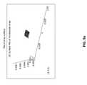
- FIG. 7shows the effective array aperture for the curved array for a particular focal distance.
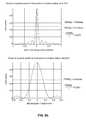
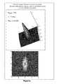
- FIG. 8 ashows a phased array configured to provide a focused acoustic beam for a simulation of the focused acoustic beam at a focal distance 5 mm away from the array surface.
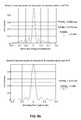
- FIG. 8 bis a graph of the resulting acoustic power at the focal point in the direction of the circumference and along the axial direction.
- FIG. 8 cis a three-dimensional presentation of the acoustic power, along with a top-down view.
- FIG. 9 ashows a phased array configured to provide a focused acoustic beam for a simulation of the focused acoustic beam at a focal distance 1 mm away from the array surface.
- FIG. 9 bis a graph of the resulting acoustic power at the focal point in the direction of the circumference and along the axial direction.
- FIG. 9 cis a three-dimensional presentation of the acoustic power, along with a top-down view.
- FIG. 10 ashows a phased array configured to provide a focused acoustic beam for a simulation of the focused acoustic beam at a focal distance 10 mm away from the array surface.
- FIG. 10 bis a graph of the resulting acoustic power at the focal point in the direction of the circumference and along the axial direction.
- FIG. 10 cis a three-dimensional presentation of the acoustic power, along with a top-down view.
- This Optical Scanning Capsule Endoscopeis a revolutionary step forward providing for 100% coverage of the intestinal tract including the small and large bowels.
- the image assembly techniquesare not specific to optical images, which provide the opportunity to replace the optical imaging hardware with ultrasound imaging.
- An Ultrasound Scanning Capsule Endoscope(USCE) is envisioned which would use ultrasound imaging elements in an annular (ring-like) array around the circumference of the capsule to produce an image of reflected acoustic energy from the body lumen wall, and would use the same signal processing algorithms to assemble sequential ring scan frames into a single continuous image of the colon. Because the ultrasound signal would be reflected from the interface between the colonic contents and the colon tissue itself, it may not be necessary to prep the patient for this procedure. This sidewall ring scanning approach, when extended to ultrasound imaging rather than optical imaging, could enable prep-less imaging of the colon for Colorectal Cancer screening.
- the OSCE technology platformeffectively implements a 256 to 512 by 16 to 32 element wide optical scanning array around the circumference of a nominally 11 millimeter diameter capsule. It operates at up to 60 frames per second to accommodate rapid peristalsis movement (up to 5 cm per second) and tumbling.
- Optical flow algorithmssimilar to those used in optical mice for computers, are used to track capsule movement. This movement information is used to vary the scan rate to minimize scan redundancy when stationary.
- Stitching algorithmssimilar to those commercially available, are used to construct a single image of the entire intestine, which can be viewed and manipulated much like Google maps.
- the scan datais transmitted from the capsule to on-body sensors using the acoustic data communication technology described herein.
- the USCEwill be implemented by replacing the optical scanning array with an ultrasound scanning array. This scanning array swap will be built on top of the technology platform developed for the OSCE. The proposed USCE technical approach is described in detail below.
- FIG. 1is an illustration of the USCE in the intestinal tract, showing how the focused acoustic energy impinges on the intestinal wall and is reflected back to the capsule.
- FIG. 2illustrates the transducer array wrapped around the circumference of the capsule. The acoustic transducers could be implemented with PZT elements, but other technologies could also be employed.
- FIG. 3shows a section of the array, illustrating its cross section.
- phased arraysignifies the part of the total array that is energized for the generation of a focused acoustic signal at a spot on the intestinal wall.
- F dS p 2 /(2 ⁇ ).
- the spot sizeis determined by ⁇ and L, both of which have practical limits.
- the wavelengthis limited by signal attenuation and L is limited by the curvature of the capsule.
- the term l f /Lis the f-number which in practice is hard to get much smaller than unity, which limits the spot size to somewhat less than 2 ⁇ , to no smaller than ⁇ .
- the depth of focusincreases as spot size increases, and some cases it may be desirable to increase the depth of focus at the expense of increased spot size, such as for when d is not well known.
- the optimization of ⁇ and L for array performanceare next considered.
- the operational frequencyneeds to be chosen so that its wavelength, ⁇ , is a multiple of the center-to-center transducer element spacing, D.
- ⁇the center-to-center transducer element spacing
- the resulting difference in array size between these two anglesis significant because of the surface curvature around the circumference of the capsule.
- the maximum focused array sizeis achieved in the limit of a very large imaging distance (going theoretically to infinity) between the intestinal wall and the center of the acoustic transducer element array where the array around the circumference would be a full third of the circumference (120°).
- L max24rK.
- L max12rK, which is half the value of L max2 . Therefore, either case for ⁇ provides for the same spot size from equation (1) in the theoretical limit of infinite image distance.
- the locations of the grating lobesare for the following parameters:
- a 10% overhead for spacing between elementsgives a net transducer element size of 60 microns on a side, with 3.25 microns between elements.
- Other design selectionswould fall under the scope of this invention.
- a practical focused array sizemay be smaller than this because of the tradeoff between spot size and operational complexity. Smaller arrays are simpler to implement, but the resulting spot size will be larger.
- the practical array sizewill be limited to 32 transducer elements in the axial direction.
- the phased arrayis set in the transmit configuration to launch a brief pulse focused to the minimum spot size at the targeted l f value, which could be the previously measured value for that voxel.
- the signalis focused by driving each element in the array with the appropriate timing so that the resulting wave front converges at the targeted spot. This is done with conventional approaches used in medical ultrasound imaging systems, except that the curvature of the array around the circumference needs to be accommodated in the signal timing to each element. Since the spot is not scanned, but is fixed to coincide with a point above the center of the array, the timing circuits are simplified by the array quadrant symmetry. So the number of timing circuits will be 1 ⁇ 4 of the total number of transducer elements in the array.
- the timing circuitsare further simplified by using one counter for the timer, with taps off the counter at the appropriate points for the correct timing of each transducer element in symmetric positions in all four quadrants. So four transducer elements are driven from each counter tap.
- the circuitryis further simplified by eliminating the 11.4 MHz oscillator circuit to drive the transducer elements for a short pulse, but by rather inducing resonant oscillation at 11.4 MHz with a brief impulse to the transducer elements. However, using an oscillator to drive the transducer elements would fall under the scope of the invention.
- the counter tapsare programmable with algorithms that take the previous measurement data to set the appropriate timing taps for the next measurement.
- the arrayis configured into the receive mode, to listen for the signal echoes.
- the same phase array timingis used in the receive mode as for the pulse transmit mode. This approach is very complex, and requires a separate “front end” at each transducer element to detect a very weak return signal.
- the transmit arrayprovides a very well defined spot signal with no grating lobes, the receive array can be greatly simplified to just a small array of transducer elements at the center of the larger transmit array.
- Medical ultrasound imagingreceives multiple echo signals to re-construct a depth image of the object.
- the USCEwill be limited by the bandwidth of the communication channel to how much data can be acquired and sent.
- the scanning operationis achieved by pulsing a single or multiple phased arrays configured around the circumference of the capsule.
- a switching arrayconfigures the array elements for the next phased array, one element over around the circumference from the previous. In this way, one or multiple voxels around the array circumference are imaged at a time in sequence until all the circumference voxels have been imaged and the surface around the pill has been mapped. Then the process repeats using previously obtained data to set the arrays for the next data acquisitions.
- This processoccurs very rapidly, resulting in a high net scan, or frame rate, whereby the capsule moves only a fraction of a voxel during peristalsis or tumbling, allowing for image stitching to capture a continuous, scanned image, as the capsule moves through the intestinal tract.
- This scanning processmeasures a limited range of echo return times around expected echo times at the beam focus.
- the reflecting surface distance from the arrayis extracted from the dominant echo return time. This extracted surface distance is used as the focal distance for the next shifted voxel “probe”. In this way the acoustic focus will closely follow the intestinal surface. An initial voxel scan will be need to gain the surface “lock”, after which the scanning will be rapid.
- the array size, Lis limited by the curvature of the capsule, as shown in FIG. 7 .
- the array sizeis given by:
- d cornerx 2 + ( L axial 2 ) 2 , ( 14 ) which for this example is 0.67 cm, providing for a round trip distance of 1.34 cm, which takes 8.7 usec.
- R pixelp t a , ( 15 ) which for this case is 0.45 M voxels/sec.
- a complete scan of all the circumference voxelstakes:
- the capsulemoves 0.09 of a spot size in the axial direction at the maximum peristalsis rate of 2 inches/sec.
- the resulting voxel overlap between scansallows for image stitching to provide a continuous scanned image. Note that the above translates the array one transducer element center-to-center distance, or 67.5 microns, around the circumference for the next transmit pulse and echo receive cycle, which is 0.25 of the spot size for the circumference array.
- the scan ratedoubles with the same data output rate, and the capsule then moves 0.045 of a spot size in the axial direction between scans, for greater voxel overlap, which enables post image processing that could increase effective resolution by at least a factor of two.
- the scan ratecan be kept the same to halve the data rate, which could be an important data bandwidth consideration.
- Prep-less colon applicationswill most likely require more echo data to resolve the signal traveling through non-homogeneous intestinal material.
- a higher data rate communication channelwill need to be employed.
- Each echo time and signal strength data pairwill require 7.2 Mbits/sec of bandwidth.
- Ten pairswould require 72 Mbits/sec, which with 10 ⁇ data compression would require a 7.2 Mbit/sec channel.
- the actual number of data pairs requiredwill most likely be less than ten, lessening the data rate requirements.
- the number of transducer elementsis 32, for an array dimension of 2 mm, which provides for a spot size of 125 microns and an f-number of 0.46. Again, because the f-number is much less than one, this spot size may not be realistically achievable. Indeed, the Mathcad simulation of FIG. 9 yields a spot size of 170 microns.
- the capsulemoves 0.08 of a spot size in the axial direction at the maximum peristalsis rate of 2 inches/sec. The resulting voxel overlap between scans allows for image stitching to provide a continuous scanned image.
- the abovetranslates the array one transducer element center-to-center distance, or 67.5 microns, around the circumference for the next transmit pulse and echo receive cycle, which is 0.3 of the spot size for the circumference array. If the array is translated two transducer elements between cycles, or a 0.6 of a circumference spot size, then the scan rate doubles with the same data output rate, and the capsule then moves 0.04 of a spot size in the axial direction between scans, for greater voxel overlap, which enables post image processing that could increase effective resolution by at least a factor of two. Conversely, the scan rate can be kept the same to halve the data rate, which could be an important data bandwidth consideration.
- the timing of individual transducer elements in the arrayneeds to be theoretically exact to provide for a converging acoustic signal wave front at the image point.
- the array elementsare fired in order of their distance away from the array center, with the corner elements of the array firing first, and the center ones last.
- the corner elementswill need to be fired 0.644 usec before the center ones.
- the timing difference between adjacent transducer elements at and near the array edgeis around 61 nsec.
- the difference of acoustic travel distancesbecomes on the order of 0.5D 2 /d between transducer elements, which for this case is 2.2 micron, or 1.5 nsec, which would require a clock frequency on the order of 670 MHz to drive a timing counter.
- the ratio of 0.644 usec/1.5 nsecis 429, which would require a 9-stage timing counter.
- the corner elementswill need to fire 1.1 usec before the center ones.
- the timing difference between adjacent transducer elements at and near the array edgeis around 114 nsec.
- the timing difference between adjacent elementsis about 0.3 nsec, which would require a clock frequency of 3.4 GHz to drive a timing counter.
- the ratio of 1.1 usec/0.3 nsecis 3367, requiring a 12-stage timing counter to accommodate.
- An upper bound for the timing difference between corner elements and the centeris for d becoming much larger than r, for which the array encompasses one third of the capsule circumference, and the difference in distance traveled to the focused spot becomes just 1 ⁇ 2 r.
- 1 ⁇ 2 r,2.75 mm, for an upper limit of 1.875 usec for when the corner elements need to fire before the center ones.
- the focused array sizes around the circumference used in the above examplesare limited by capsule curvature.
- the resulting arrayprovided an f-number of 0.4, which is less than is practically achievable.
- Thisprovides for the possibility of reducing the array size to achieve an f-number that is more practically achievable.
- the disadvantageis that actual spot size will increase.
- dthe distance from the surface to the intestinal wall varies around the circumference.
- This situationwill require dynamic array size configuration around the circumference as positions change.
- dmay vary from 1 mm on one side of the capsule to 5 mm on the other side.
- the array sizewill vary to accommodate the changing value of d.
- the scan ratewill also vary to accommodate the changing timing conditions of the array size. Stepping distance can also vary, as described above, to increase scan rate to maintain the desired amount of voxel overlap in the axial direction.
- This dynamic array environmentwill be directed by a central controller, which controls all aspects of array timing and size.
- the same timingis used for the receive elements to minimize image artifacts.
- a simpler methodis proposed, where only a block of transducer elements in the center of the array are is used as the receiver.
- the receive arraycontains a total of 16 transducer elements.
- the considerations for the number of receive array elementsare by way of example only, and other considerations could yield a different number of receive array elements and still fall under the scope of the invention.
- the receive arrayis configured as soon as the signal transmission cycle is completed and the signal oscillations are dampened.
- a clock timeris initiated, and the receive array starts listening for the echo signal from the intestinal wall tissue, distance d away from the array.
Landscapes
- Engineering & Computer Science (AREA)
- Physics & Mathematics (AREA)
- Health & Medical Sciences (AREA)
- Life Sciences & Earth Sciences (AREA)
- Radar, Positioning & Navigation (AREA)
- Remote Sensing (AREA)
- Computer Networks & Wireless Communication (AREA)
- General Physics & Mathematics (AREA)
- Acoustics & Sound (AREA)
- Pathology (AREA)
- Medical Informatics (AREA)
- Nuclear Medicine, Radiotherapy & Molecular Imaging (AREA)
- Veterinary Medicine (AREA)
- Radiology & Medical Imaging (AREA)
- Biomedical Technology (AREA)
- Heart & Thoracic Surgery (AREA)
- Biophysics (AREA)
- Molecular Biology (AREA)
- Surgery (AREA)
- Animal Behavior & Ethology (AREA)
- General Health & Medical Sciences (AREA)
- Public Health (AREA)
- Gynecology & Obstetrics (AREA)
- Ultra Sonic Daignosis Equipment (AREA)
Abstract
Description
Sp=2λlf/L, (1)
where L is the side dimension of the phased array, and lfis the focal length, given by the distance, d, from the array center to the intestinal wall. The wavelength of the sinusoidal acoustic signal is λ=c/f where c=1540 meters/sec is the speed of sound in the aqueous environment of the intestinal track, and f is the signal frequency.
Fd=Sp2/(2λ). (2)
For a given focal length, the spot size is determined by λ and L, both of which have practical limits. The wavelength is limited by signal attenuation and L is limited by the curvature of the capsule. The term lf/L is the f-number which in practice is hard to get much smaller than unity, which limits the spot size to somewhat less than 2λ, to no smaller than λ. The depth of focus increases as spot size increases, and some cases it may be desirable to increase the depth of focus at the expense of increased spot size, such as for when d is not well known. The optimization of λ and L for array performance are next considered.
Θ=sin−1(Kλ/D), (3)
where K=0.433 for the half power point of the signal.
Θ=360°/N (4)
where N is the number of acoustic transducer elements around the circumference. The maximum array size for the circumference transducer elements is limited by the resultant curvature angle of the edge elements relative to the image spot. For λ=2D, this will be the Θ=60° divergence angle. The maximum focused array size is achieved in the limit of a very large imaging distance (going theoretically to infinity) between the intestinal wall and the center of the acoustic transducer element array where the array around the circumference would be a full third of the circumference (120°). However, the effective array aperture is the planar projection of this arc as shown in
Lmax2rsin(Θ)=2rKλ/D, (5)
from equation (3) above, and
where r is the radius of curvature of the capsule. For Θ=60° provided by λ=2D, Lmax2=4rK. For Θ=26° provided by λ=D, Lmax1=2rK, which is half the value of Lmax2. Therefore, either case for λ provides for the same spot size from equation (1) in the theoretical limit of infinite image distance. Using Lmaxin equation (1) shows that for L near Lmaxthe spot size in the circumference direction increases linearly with d=lf:
Laxial=2lftan(Θ). (7)
For Θ=60°, provided by λ=2D, Laxial=3.5 lf, for which the f-number=lf/Laxial=0.29. The spot size in the axial direction is then:
Because the f-number is much less than one, this spot size is probably not practically achievable. For Θ=26°, provided by λ=D, Laxial=lf, for which the f-number=1 and the spot size in the axial direction is:
Spaxial=2D. (9)
Ψgn=sin−1(nλ/D) (10)
where the center to center spacing of the transducer elements, D, is shown in
where r is the capsule radius. For d=5 mm, L=6 mm, and the selected phased array has 94 circumference transducer elements on a side. Using this value of L in equation (1) provides a theoretical spot size of 225 microns in the circumference direction, which provides the projected voxel size on the intestinal wall. The Mathcad simulation of
which for this example is 0.67 cm, providing for a round trip distance of 1.34 cm, which takes 8.7 usec. The total voxel acquisition time is therefore ta=8.87 usec, which establishes the maximum voxel acquisition rate of:
which for this case is 0.45 M voxels/sec. A complete scan of all the circumference voxels takes:
which for this case is 1.135 msec, providing for a scan rate of 881 scans/sec where each scan is comprised of 512 circumference voxels. During one scan the capsule moves 0.09 of a spot size in the axial direction at the maximum peristalsis rate of 2 inches/sec. The resulting voxel overlap between scans allows for image stitching to provide a continuous scanned image. Note that the above translates the array one transducer element center-to-center distance, or 67.5 microns, around the circumference for the next transmit pulse and echo receive cycle, which is 0.25 of the spot size for the circumference array. If the array is translated two transducer elements between cycles, or a 0.5 of a circumference spot size, then the scan rate doubles with the same data output rate, and the capsule then moves 0.045 of a spot size in the axial direction between scans, for greater voxel overlap, which enables post image processing that could increase effective resolution by at least a factor of two. Conversely, the scan rate can be kept the same to halve the data rate, which could be an important data bandwidth consideration.
Claims (22)
Priority Applications (3)
| Application Number | Priority Date | Filing Date | Title |
|---|---|---|---|
| US13/073,424US8647259B2 (en) | 2010-03-26 | 2011-03-28 | Ultrasound scanning capsule endoscope (USCE) |
| US14/147,124US9480459B2 (en) | 2010-03-26 | 2014-01-03 | Ultrasound scanning capsule endoscope |
| US15/337,188US20170042506A1 (en) | 2010-03-26 | 2016-10-28 | Ultrasound scanning capsule endoscope |
Applications Claiming Priority (2)
| Application Number | Priority Date | Filing Date | Title |
|---|---|---|---|
| US31801210P | 2010-03-26 | 2010-03-26 | |
| US13/073,424US8647259B2 (en) | 2010-03-26 | 2011-03-28 | Ultrasound scanning capsule endoscope (USCE) |
Related Child Applications (1)
| Application Number | Title | Priority Date | Filing Date |
|---|---|---|---|
| US14/147,124ContinuationUS9480459B2 (en) | 2010-03-26 | 2014-01-03 | Ultrasound scanning capsule endoscope |
Publications (2)
| Publication Number | Publication Date |
|---|---|
| US20120101386A1 US20120101386A1 (en) | 2012-04-26 |
| US8647259B2true US8647259B2 (en) | 2014-02-11 |
Family
ID=45973565
Family Applications (3)
| Application Number | Title | Priority Date | Filing Date |
|---|---|---|---|
| US13/073,424Active - ReinstatedUS8647259B2 (en) | 2010-03-26 | 2011-03-28 | Ultrasound scanning capsule endoscope (USCE) |
| US14/147,124Active - Reinstated2031-04-25US9480459B2 (en) | 2010-03-26 | 2014-01-03 | Ultrasound scanning capsule endoscope |
| US15/337,188AbandonedUS20170042506A1 (en) | 2010-03-26 | 2016-10-28 | Ultrasound scanning capsule endoscope |
Family Applications After (2)
| Application Number | Title | Priority Date | Filing Date |
|---|---|---|---|
| US14/147,124Active - Reinstated2031-04-25US9480459B2 (en) | 2010-03-26 | 2014-01-03 | Ultrasound scanning capsule endoscope |
| US15/337,188AbandonedUS20170042506A1 (en) | 2010-03-26 | 2016-10-28 | Ultrasound scanning capsule endoscope |
Country Status (1)
| Country | Link |
|---|---|
| US (3) | US8647259B2 (en) |
Cited By (2)
| Publication number | Priority date | Publication date | Assignee | Title |
|---|---|---|---|---|
| US20130274607A1 (en)* | 2010-12-22 | 2013-10-17 | Koninklijke Philips Electronics N.V. | Automated doppler velocimetry using a low-cost transducer |
| US9480459B2 (en) | 2010-03-26 | 2016-11-01 | Innurvation, Inc. | Ultrasound scanning capsule endoscope |
Families Citing this family (5)
| Publication number | Priority date | Publication date | Assignee | Title |
|---|---|---|---|---|
| US9462968B2 (en) | 2014-10-17 | 2016-10-11 | General Electric Company | System and method for assessing bowel health |
| KR101851724B1 (en)* | 2017-09-05 | 2018-04-24 | 심한보 | Swallowable device |
| CN108303699B (en)* | 2018-01-29 | 2020-02-14 | 中国人民解放军国防科技大学 | Ultrasonic phased array far-field super-resolution imaging method, device, storage medium and system |
| JP7070806B2 (en)* | 2019-11-07 | 2022-05-18 | 株式会社村田製作所 | Dosing detection system and medication device |
| WO2022109867A1 (en)* | 2020-11-25 | 2022-06-02 | Shenzhen Xpectvision Technology Co., Ltd. | Imaging systems |
Citations (222)
| Publication number | Priority date | Publication date | Assignee | Title |
|---|---|---|---|---|
| US2788390A (en) | 1952-10-16 | 1957-04-09 | Sheldon Edward Emanuel | Device for examination of inaccessible parts |
| US2987960A (en) | 1958-02-17 | 1961-06-13 | Bausch & Lomb | Optical system for endoscopes and the like |
| US3329074A (en) | 1963-07-01 | 1967-07-04 | Iota Cam Corp | Instrument for visual inspection |
| US3608547A (en) | 1967-07-29 | 1971-09-28 | Olympus Optical Co | Method for determining the distance of an object from an edoscope |
| US3730175A (en) | 1971-03-24 | 1973-05-01 | Olympus Optical Co | Endoscope |
| US4987897A (en) | 1989-09-18 | 1991-01-29 | Medtronic, Inc. | Body bus medical device communication system |
| US5010412A (en) | 1988-12-27 | 1991-04-23 | The Boeing Company | High frequency, low power light source for video camera |
| US5131398A (en) | 1990-01-22 | 1992-07-21 | Mediscience Technology Corp. | Method and apparatus for distinguishing cancerous tissue from benign tumor tissue, benign tissue or normal tissue using native fluorescence |
| US5251326A (en) | 1990-09-17 | 1993-10-05 | Michael Silverman | Two way communication system for water sports |
| US5267033A (en) | 1990-11-28 | 1993-11-30 | Dai Nippon Printing Co., Ltd. | Hollow body inspection system, hollow body inspection apparatus and signal transmission apparatus |
| US5265603A (en) | 1990-12-12 | 1993-11-30 | Medtronic, Inc. | Electronic capture detection for a pacer |
| US5279607A (en) | 1991-05-30 | 1994-01-18 | The State University Of New York | Telemetry capsule and process |
| US5329498A (en) | 1993-05-17 | 1994-07-12 | Hewlett-Packard Company | Signal conditioning and interconnection for an acoustic transducer |
| US5395366A (en) | 1991-05-30 | 1995-03-07 | The State University Of New York | Sampling capsule and process |
| US5522865A (en) | 1989-09-22 | 1996-06-04 | Alfred E. Mann Foundation For Scientific Research | Voltage/current control system for a human tissue stimulator |
| US5559757A (en) | 1991-12-18 | 1996-09-24 | Catipovic; Josko A. | Spatial diversity processing for underwater acoustic telemetry |
| US5604531A (en) | 1994-01-17 | 1997-02-18 | State Of Israel, Ministry Of Defense, Armament Development Authority | In vivo video camera system |
| US5741311A (en) | 1996-06-27 | 1998-04-21 | Medtronic, Inc. | Implantable medical device system with method for determining lead condition |
| US5744898A (en) | 1992-05-14 | 1998-04-28 | Duke University | Ultrasound transducer array with transmitter/receiver integrated circuitry |
| US5796827A (en) | 1996-11-14 | 1998-08-18 | International Business Machines Corporation | System and method for near-field human-body coupling for encrypted communication with identification cards |
| US5833603A (en) | 1996-03-13 | 1998-11-10 | Lipomatrix, Inc. | Implantable biosensing transponder |
| US5984875A (en) | 1997-08-22 | 1999-11-16 | Innotek Pet Products, Inc. | Ingestible animal temperature sensor |
| US5993378A (en)* | 1980-10-28 | 1999-11-30 | Lemelson; Jerome H. | Electro-optical instruments and methods for treating disease |
| US5995136A (en) | 1992-05-13 | 1999-11-30 | Olympus Optical Co., Ltd. | Frame sequential type imaging apparatus for obtaining high resolution object image by irradiating frame sequential light on the object, photoelectrically converting the object image and processing signals by a solid state imaging device |
| US6076016A (en) | 1995-10-19 | 2000-06-13 | Feierbach; Gary F. | Galvanic transdermal conduction communication system and method |
| US6104913A (en) | 1998-03-11 | 2000-08-15 | Bell Atlantic Network Services, Inc. | Personal area network for personal telephone services |
| US6115636A (en) | 1998-12-22 | 2000-09-05 | Medtronic, Inc. | Telemetry for implantable devices using the body as an antenna |
| US6172789B1 (en) | 1999-01-14 | 2001-01-09 | The Board Of Trustees Of The Leland Stanford Junior University | Light scanning device and confocal optical device using the same |
| US6198965B1 (en) | 1997-12-30 | 2001-03-06 | Remon Medical Technologies, Ltd. | Acoustic telemetry system and method for monitoring a rejection reaction of a transplanted organ |
| US6211799B1 (en) | 1997-11-06 | 2001-04-03 | Massachusetts Institute Of Technology | Method and apparatus for transbody transmission of power and information |
| US6240312B1 (en) | 1997-10-23 | 2001-05-29 | Robert R. Alfano | Remote-controllable, micro-scale device for use in in vivo medical diagnosis and/or treatment |
| US6239724B1 (en) | 1997-12-30 | 2001-05-29 | Remon Medical Technologies, Ltd. | System and method for telemetrically providing intrabody spatial position |
| US6294775B1 (en) | 1999-06-08 | 2001-09-25 | University Of Washington | Miniature image acquistion system using a scanning resonant waveguide |
| US20010035902A1 (en) | 2000-03-08 | 2001-11-01 | Iddan Gavriel J. | Device and system for in vivo imaging |
| US20020032366A1 (en) | 1997-12-15 | 2002-03-14 | Iddan Gavriel J. | Energy management of a video capsule |
| US6380858B1 (en) | 1999-12-29 | 2002-04-30 | Becton, Dickinson And Company | Systems and methods for monitoring patient compliance with medication regimens |
| USD457236S1 (en) | 2000-08-21 | 2002-05-14 | Given Imaging Ltd. | Capsule with a handle |
| USD457621S1 (en) | 2000-08-21 | 2002-05-21 | Given Imaging Ltd. | Tapering capsule |
| USD457948S1 (en) | 2000-08-21 | 2002-05-28 | Given Imaging Ltd. | Concave capsule |
| WO2002055984A2 (en) | 2001-01-16 | 2002-07-18 | Given Imaging Ltd. | A system and method for determining in vivo body lumen conditions |
| WO2002054932A2 (en) | 2001-01-16 | 2002-07-18 | Given Imaging Ltd. | System and method for wide field imaging of body lumens |
| WO2002055126A2 (en) | 2001-01-11 | 2002-07-18 | Given Imaging Ltd. | Device and system for in-vivo procedures |
| US6431175B1 (en) | 1997-12-30 | 2002-08-13 | Remon Medical Technologies Ltd. | System and method for directing and monitoring radiation |
| WO2002073507A2 (en) | 2001-03-14 | 2002-09-19 | Given Imaging Ltd. | Method and system for detecting colorimetric abnormalities |
| US20020138009A1 (en) | 1998-09-24 | 2002-09-26 | Data Sciences International, Inc. | Implantable sensor with wireless communication |
| WO2002080376A2 (en) | 2001-03-29 | 2002-10-10 | Given Imaging Ltd. | A method for timing control |
| USD464425S1 (en) | 2000-08-21 | 2002-10-15 | Given Imaging Ltd. | Tapering capsule |
| WO2002080753A2 (en) | 2001-04-04 | 2002-10-17 | Given Imaging Ltd. | Induction powered in vivo imaging device |
| US20020168144A1 (en) | 2001-04-30 | 2002-11-14 | Xerox Corporation | Micro-opto-electro-mechanical system (MOEMS) |
| WO2002089913A2 (en) | 2001-05-05 | 2002-11-14 | Toumaz Technology Limited | Fully implantable cochlear implant system and electronic circuits therefor |
| US20020173718A1 (en) | 2001-05-20 | 2002-11-21 | Mordechai Frisch | Array system and method for locating an in vivo signal source |
| US6486588B2 (en) | 1997-12-30 | 2002-11-26 | Remon Medical Technologies Ltd | Acoustic biosensor for monitoring physiological conditions in a body implantation site |
| WO2002094337A2 (en) | 2001-05-20 | 2002-11-28 | Given Imaging Ltd. | A method for in vivo imaging of an unmodified gastrointestinal tract |
| US20020193669A1 (en) | 2000-05-31 | 2002-12-19 | Arkady Glukhovsky | Method for measurement of electrical characteristics of tissue |
| US20020198470A1 (en) | 2001-06-26 | 2002-12-26 | Imran Mir A. | Capsule and method for treating or diagnosing the intestinal tract |
| US6504286B1 (en) | 1997-12-30 | 2003-01-07 | Remon Medical Technologies Ltd. | Piezoelectric transducer |
| WO2003003706A2 (en) | 2001-06-28 | 2003-01-09 | Given Imaging Ltd. | In vivo imaging device with a small cross sectional area |
| US20030013370A1 (en) | 2001-07-05 | 2003-01-16 | Arkady Glukhovsky | Device and method for attenuating radiation from in vivo electrical devices |
| US20030018280A1 (en) | 2001-05-20 | 2003-01-23 | Shlomo Lewkowicz | Floatable in vivo sensing device and method for use |
| US20030020810A1 (en)* | 2001-07-30 | 2003-01-30 | Olympus Optical Co., Ltd. | Capsule-type medical apparatus |
| USD469864S1 (en) | 2000-11-22 | 2003-02-04 | Given Imaging Ltd. | Capsule with expanded membrane |
| WO2003010967A1 (en) | 2001-07-26 | 2003-02-06 | Given Imaging Ltd. | Diagnostic device using data compression |
| US20030028078A1 (en) | 2001-08-02 | 2003-02-06 | Arkady Glukhovsky | In vivo imaging device, system and method |
| US20030040685A1 (en) | 2001-07-12 | 2003-02-27 | Shlomo Lewkowicz | Device and method for examining a body lumen |
| US20030045790A1 (en) | 2001-09-05 | 2003-03-06 | Shlomo Lewkowicz | System and method for three dimensional display of body lumens |
| WO2003028224A2 (en) | 2001-09-24 | 2003-04-03 | Given Imaging Ltd. | System and method for controlling a device in vivo |
| US20030077223A1 (en) | 2001-06-20 | 2003-04-24 | Arkady Glukhovsky | Motility analysis within a gastrointestinal tract |
| US6563105B2 (en) | 1999-06-08 | 2003-05-13 | University Of Washington | Image acquisition with depth enhancement |
| US20030117491A1 (en) | 2001-07-26 | 2003-06-26 | Dov Avni | Apparatus and method for controlling illumination in an in-vivo imaging device |
| WO2003053241A2 (en) | 2001-12-20 | 2003-07-03 | Given Imaging Ltd. | Device, system and method for image based size analysis |
| EP1326432A2 (en) | 2001-12-18 | 2003-07-09 | Given Imaging Ltd. | Device, system and method for capturing in-vivo images with three-dimensional aspects |
| US6597320B2 (en) | 2000-09-11 | 2003-07-22 | Nippon Soken, Inc. | Antenna for portable radio communication device and method of transmitting radio signal |
| US20030139647A1 (en) | 2000-05-23 | 2003-07-24 | Dan Raz | Device and method for positioning an object in a body lumen |
| US20030139661A1 (en) | 2001-01-22 | 2003-07-24 | Yoav Kimchy | Ingestible device |
| US6607301B1 (en) | 1999-08-04 | 2003-08-19 | Given Imaging Ltd. | Device and method for dark current noise temperature sensing in an imaging device |
| US6628989B1 (en) | 2000-10-16 | 2003-09-30 | Remon Medical Technologies, Ltd. | Acoustic switch and apparatus and methods for using acoustic switches within a body |
| US6632171B2 (en) | 1997-12-22 | 2003-10-14 | Given Imaging Ltd. | Method for in vivo delivery of autonomous capsule |
| US20030195415A1 (en) | 2002-02-14 | 2003-10-16 | Iddan Gavriel J. | Device, system and method for accoustic in-vivo measuring |
| US20040027500A1 (en) | 2002-02-12 | 2004-02-12 | Tal Davidson | System and method for displaying an image stream |
| WO2004014227A1 (en) | 2002-08-13 | 2004-02-19 | Given Imaging Ltd. | System for in vivo sampling and analysis |
| US20040032187A1 (en) | 1997-12-30 | 2004-02-19 | Remon Medical Technologies Ltd. | Devices for intrabody delivery of molecules and systems and methods utilizing same |
| US6702755B1 (en) | 2001-05-17 | 2004-03-09 | Dymedix, Corp. | Signal processing circuit for pyro/piezo transducer |
| US20040073087A1 (en) | 2000-05-15 | 2004-04-15 | Arkady Glukhovsky | System and method for controlling in vivo camera capture and display rate |
| US20040109488A1 (en) | 1999-08-04 | 2004-06-10 | Arkady Glukhovsky | Device, system and method for temperature sensing in an in-vivo device |
| US20040114856A1 (en) | 2001-11-08 | 2004-06-17 | Xerox Corporation | Monolithic reconfigurable optical multiplexer systems and methods |
| US6754472B1 (en) | 2000-04-27 | 2004-06-22 | Microsoft Corporation | Method and apparatus for transmitting power and data using the human body |
| US20040122315A1 (en) | 2002-09-24 | 2004-06-24 | Krill Jerry A. | Ingestible medical payload carrying capsule with wireless communication |
| WO2004052209A1 (en) | 2002-12-11 | 2004-06-24 | Koninklijke Philips Electronics N.V. | Miniaturized ultrasonic transducer |
| USD492403S1 (en) | 2003-01-06 | 2004-06-29 | Given Imaging Ltd. | Spherical capsule |
| WO2004054430A2 (en) | 2002-12-16 | 2004-07-01 | Given Imaging Ltd. | Device, system and method for selective activation of in vivo sensors |
| US20040127785A1 (en) | 2002-12-17 | 2004-07-01 | Tal Davidson | Method and apparatus for size analysis in an in vivo imaging system |
| WO2004058041A2 (en) | 2002-12-26 | 2004-07-15 | Given Imaging Ltd. | Immobilizable in vivo sensing device |
| US6764446B2 (en) | 2000-10-16 | 2004-07-20 | Remon Medical Technologies Ltd | Implantable pressure sensors and methods for making and using them |
| US20040171915A1 (en) | 2002-11-29 | 2004-09-02 | Arkady Glukhovsky | Method and apparatus for transmitting non-image information in an in vivo imaging system |
| US20040176685A1 (en)* | 2003-03-04 | 2004-09-09 | Olympus Corporation | Capsule medical apparatus and capsule medical apparatus collecting system |
| US20040181155A1 (en) | 2002-04-25 | 2004-09-16 | Arkady Glukhovsky | Device and method for in-vivo sensing |
| US20040199222A1 (en) | 2002-06-06 | 2004-10-07 | Mingui Sun | Method of data communication with implanted device and associated apparatus |
| US20040199054A1 (en) | 2003-04-03 | 2004-10-07 | Wakefield Glenn Mark | Magnetically propelled capsule endoscopy |
| US20040199061A1 (en) | 2001-08-02 | 2004-10-07 | Arkady Glukhovsky | Apparatus and methods for in vivo imaging |
| US20040202339A1 (en) | 2003-04-09 | 2004-10-14 | O'brien, William D. | Intrabody communication with ultrasound |
| US20040204744A1 (en) | 2003-04-14 | 2004-10-14 | Remon Medicaltechnologies Ltd. | Apparatus and methods using acoustic telemetry for intrabody communications |
| US20040210105A1 (en) | 2003-04-21 | 2004-10-21 | Hale Eric Lawrence | Method for capturing and displaying endoscopic maps |
| WO2004096008A2 (en) | 2003-05-01 | 2004-11-11 | Given Imaging Ltd. | Panoramic field of view imaging device |
| US20040240077A1 (en) | 1999-06-15 | 2004-12-02 | Hanoch Kislev | Optical system |
| EP1492352A2 (en) | 2003-06-26 | 2004-12-29 | Given Imaging Ltd. | Device, method and system for reduced transmission imaging |
| US6845190B1 (en) | 2000-11-27 | 2005-01-18 | University Of Washington | Control of an optical fiber scanner |
| US6855111B2 (en) | 2002-03-08 | 2005-02-15 | Olympus Corporation | Capsule endoscope |
| US6856712B2 (en) | 2000-11-27 | 2005-02-15 | University Of Washington | Micro-fabricated optical waveguide for use in scanning fiber displays and scanned fiber image acquisition |
| US6867753B2 (en) | 2002-10-28 | 2005-03-15 | University Of Washington | Virtual image registration in augmented display field |
| US20050065441A1 (en) | 2003-08-29 | 2005-03-24 | Arkady Glukhovsky | System, apparatus and method for measurement of motion parameters of an in-vivo device |
| US20050068416A1 (en) | 1999-06-15 | 2005-03-31 | Arkady Glukhovsky | In-vivo imaging device, optical system and method |
| US20050075555A1 (en) | 2002-05-09 | 2005-04-07 | Arkady Glukhovsky | System and method for in vivo sensing |
| US20050088299A1 (en) | 2003-10-24 | 2005-04-28 | Bandy William R. | Radio frequency identification (RFID) based sensor networks |
| US20050096526A1 (en)* | 2003-10-08 | 2005-05-05 | Siemens Aktiengesellschaft | Endoscopy device comprising an endoscopy capsule or an endoscopy head with an image recording device, and imaging method for such an endoscopy device |
| US20050119577A1 (en)* | 2003-11-06 | 2005-06-02 | Olympus Corporation | Intracoelomic mobile body, and capsule-type ultrasonic endoscope |
| US20050143644A1 (en) | 2003-12-31 | 2005-06-30 | Given Imaging Ltd. | In-vivo sensing device with alterable fields of view |
| WO2005062715A2 (en) | 2003-12-31 | 2005-07-14 | Given Imaging Ltd. | System and method for displaying an image stream |
| US6918872B2 (en) | 2002-03-08 | 2005-07-19 | Olympus Corporation | Capsule endoscope |
| US20050159643A1 (en) | 2001-07-26 | 2005-07-21 | Ofra Zinaty | In-vivo imaging device providing data compression |
| US20050171398A1 (en) | 2002-12-26 | 2005-08-04 | Given Imaging Ltd. | In vivo imaging device and method of manufacture thereof |
| US20050177026A1 (en) | 2004-02-09 | 2005-08-11 | Hoeg Hans D. | Endoscope with variable direction of view module |
| US6934573B1 (en) | 2001-07-23 | 2005-08-23 | Given Imaging Ltd. | System and method for changing transmission from an in vivo sensing device |
| US20050187433A1 (en) | 2001-07-26 | 2005-08-25 | Given Imaging Ltd. | In-vivo imaging device providing constant bit rate transmission |
| US6936003B2 (en) | 2002-10-29 | 2005-08-30 | Given Imaging Ltd | In-vivo extendable element device and system, and method of use |
| US6939292B2 (en) | 2001-06-20 | 2005-09-06 | Olympus Corporation | Capsule type endoscope |
| US6939290B2 (en) | 2002-02-11 | 2005-09-06 | Given Imaging Ltd | Self propelled device having a magnetohydrodynamic propulsion system |
| US20050203417A1 (en)* | 2002-09-24 | 2005-09-15 | Olympus Corporation | Ultrasonic diagnosis apparatus |
| USD510139S1 (en) | 2004-07-21 | 2005-09-27 | Given Imaging Ltd | Imaging device |
| US6950690B1 (en) | 1998-10-22 | 2005-09-27 | Given Imaging Ltd | Method for delivering a device to a target location |
| US20050228275A1 (en)* | 2002-09-27 | 2005-10-13 | Olympus Corporation | Ultrasonic diagnosing system |
| US6958034B2 (en) | 2002-02-11 | 2005-10-25 | Given Imaging Ltd. | Self propelled device |
| USD512150S1 (en) | 2004-01-05 | 2005-11-29 | Given Imaging Ltd | In-vivo device |
| GB2414408A (en) | 2004-05-29 | 2005-11-30 | Zarlink Semiconductor Ltd | Implanted pacemaker with antenna formed on or by the device enclosure |
| US20050266074A1 (en) | 2004-05-20 | 2005-12-01 | Yoel Zilberstein | Ingestible device platform for the colon |
| US6975898B2 (en) | 2000-06-19 | 2005-12-13 | University Of Washington | Medical imaging, diagnosis, and therapy using a scanning single optical fiber system |
| US20050279799A1 (en)* | 2004-06-07 | 2005-12-22 | Olympus Corporation | Medical equipment storage belt |
| US20060004256A1 (en) | 2002-09-30 | 2006-01-05 | Zvika Gilad | Reduced size imaging device |
| US6984205B2 (en) | 1999-03-01 | 2006-01-10 | Gazdzinski Robert F | Endoscopic smart probe and method |
| US20060009818A1 (en) | 2004-07-09 | 2006-01-12 | Von Arx Jeffrey A | Method and apparatus of acoustic communication for implantable medical device |
| WO2006005075A2 (en) | 2004-06-30 | 2006-01-12 | Amir Belson | Apparatus and methods for capsule endoscopy of the esophagus |
| US6986738B2 (en) | 2001-08-06 | 2006-01-17 | Given Imaging Ltd | System and method for maneuvering a device in vivo |
| US20060036131A1 (en) | 2001-08-02 | 2006-02-16 | Arkady Glukhovsky | In vivo imaging device, system and method |
| US20060045118A1 (en) | 2004-09-01 | 2006-03-02 | Hyoung Chang H | Communication system using near field and method thereof |
| WO2006034125A2 (en) | 2004-09-16 | 2006-03-30 | Cohen Daniel E | Sound and vibration transmission pad and system |
| US7024248B2 (en) | 2000-10-16 | 2006-04-04 | Remon Medical Technologies Ltd | Systems and methods for communicating with implantable devices |
| US7022066B2 (en) | 2002-03-08 | 2006-04-04 | Olympus Corporation | Capsule endoscope |
| US20060074275A1 (en) | 2004-09-27 | 2006-04-06 | Tal Davidson | System and method for editing an image stream captured in vivo |
| US7039453B2 (en) | 2000-02-08 | 2006-05-02 | Tarun Mullick | Miniature ingestible capsule |
| US20060092908A1 (en) | 2004-10-07 | 2006-05-04 | Electronics And Telecommunications Research Institute | Communication apparatus using a transmission medium and method for the same |
| EP1654983A1 (en) | 2004-11-04 | 2006-05-10 | Given Imaging Ltd. | Apparatus and method for receiving, selecting and combining signals |
| WO2006059331A2 (en) | 2004-12-01 | 2006-06-08 | Given Imaging Ltd. | Two-way communication in an autonomous in vivo device |
| US7060094B2 (en)* | 2000-08-07 | 2006-06-13 | Ophthalmotronics, Inc. | Accommodating zonular mini-bridge implants |
| WO2006070367A2 (en) | 2004-12-30 | 2006-07-06 | Given Imaging Ltd. | Device, system, and method for optical in-vivo analysis |
| US20060147037A1 (en) | 2003-02-07 | 2006-07-06 | Boschetti Paolo S | Device for transforming a digital signal into an acoustic one, and that makes use of a standard phase modulation |
| US20060149132A1 (en) | 2004-12-30 | 2006-07-06 | Given Imaging Ltd. | Device and method for in vivo illumination |
| US20060184039A1 (en) | 2001-07-26 | 2006-08-17 | Dov Avni | Apparatus and method for light control in an in-vivo imaging device |
| EP1698278A1 (en) | 2003-12-25 | 2006-09-06 | Olympus Corporation | System for sensing position in subject |
| US7109859B2 (en) | 2002-12-23 | 2006-09-19 | Gentag, Inc. | Method and apparatus for wide area surveillance of a terrorist or personal threat |
| EP1704812A1 (en) | 2004-01-14 | 2006-09-27 | Olympus Corporation | Encapsulated endoscope |
| WO2006103665A2 (en) | 2005-03-29 | 2006-10-05 | Dune Medical Devices Ltd. | Electromagnetic sensors for tissue characterization |
| US7119814B2 (en) | 2001-05-18 | 2006-10-10 | Given Imaging Ltd. | System and method for annotation on a moving image |
| US7122001B2 (en) | 2002-04-08 | 2006-10-17 | Olympus Corporation | Encapsulated endoscope system in which endoscope moves in lumen by itself and rotation of image of region to be observed is ceased |
| US20060232668A1 (en) | 2005-04-18 | 2006-10-19 | Given Imaging Ltd. | Color filter array with blue elements |
| US20060238879A1 (en) | 2005-04-25 | 2006-10-26 | Takayoshi Togino | Rotationally asymmetric optical system |
| WO2006114649A1 (en) | 2005-04-26 | 2006-11-02 | Bio-Nano Sensium Technologies Limited | Sensor configuration |
| US20060252371A1 (en) | 2005-04-18 | 2006-11-09 | Sony Corporation | Human body communication system and communication device |
| US20060252986A1 (en)* | 2004-01-07 | 2006-11-09 | Olympus Corporation | Capsule-type medical apparatus, medical capsule housing, and production method thereof |
| EP1737124A2 (en) | 2005-06-14 | 2006-12-27 | Given Imaging Ltd. | Modulator and method for producing a modulated signal |
| US20070002604A1 (en) | 2005-06-24 | 2007-01-04 | Xerox Corporation | Electromechanical memory cell with torsional movement |
| US20070002135A1 (en) | 1999-06-15 | 2007-01-04 | Arkady Glukhovsky | In-vivo imaging device, optical system and method |
| US20070043310A1 (en) | 2005-03-07 | 2007-02-22 | Juvent Inc. | Method and apparatus for monitoring patient compliance during dynamic motion therapy |
| US20070060798A1 (en) | 2005-09-15 | 2007-03-15 | Hagai Krupnik | System and method for presentation of data streams |
| US20070060979A1 (en) | 2004-06-10 | 2007-03-15 | Ndi Medical, Llc | Implantable pulse generator systems and methods for providing functional and / or therapeutic stimulation of muscles and / or nerves and / or central nervous system tissue |
| US7195588B2 (en) | 2004-03-01 | 2007-03-27 | Olympus Corporation | Endoscope image pick-up apparatus |
| US20070078335A1 (en) | 2005-09-30 | 2007-04-05 | Eli Horn | System and method for in-vivo feature detection |
| USD543272S1 (en) | 2005-05-19 | 2007-05-22 | Given-Imaging, Ltd. | Imaging device |
| US20070123772A1 (en) | 2005-07-20 | 2007-05-31 | Neil Euliano | Medication compliance system and associated methods |
| WO2007028035A3 (en) | 2005-09-01 | 2007-06-07 | Proteus Biomedical Inc | Implantable zero-wire communications system |
| US7251383B2 (en) | 2002-11-27 | 2007-07-31 | Given Imaging Ltd. | Method and device of imaging with an imager having a fiber plate cover |
| US20070185381A1 (en)* | 2005-12-20 | 2007-08-09 | Olympus Medical Systems Corp. | In-vivo image capturing apparatus |
| US20070213659A1 (en) | 2004-08-27 | 2007-09-13 | Koninklijke Philips Electronics, N.V. | Electronically and remotely controlled pill and system for delivering at least one medicament |
| US20070221233A1 (en)* | 2005-12-28 | 2007-09-27 | Olympus Medical Systems Corp. | Body-insertable device system and in-vivo observation method |
| US20070232874A1 (en) | 2003-10-03 | 2007-10-04 | Can Ince | System and method for imaging the reflectance of a substrate |
| WO2007126247A1 (en) | 2006-04-28 | 2007-11-08 | Intromedic. Co., Ltd | Device for generating a signal and method for controlling operation of the same |
| WO2007126246A2 (en) | 2006-04-28 | 2007-11-08 | Intromedic. Co., Ltd | Method for processing an image in a capsule endoscope system, and capsule endoscope system |
| US7295226B1 (en) | 1999-11-15 | 2007-11-13 | Given Imaging Ltd. | Method for activating an image collecting process |
| US20070265496A1 (en)* | 2005-12-28 | 2007-11-15 | Olympus Medical Systems Corp. | Body-insertable device system and body-insertable device guiding method |
| US20070264732A1 (en)* | 2006-03-10 | 2007-11-15 | Jingkuang Chen | Three-Dimensional, Ultrasonic Transducer Arrays, Methods of Making Ultrasonic Transducer Arrays, and Devices Including Ultrasonic Transducer Arrays |
| US20070282156A1 (en) | 2004-06-16 | 2007-12-06 | Maurits Konings | Apparatus For Generating Electric Current Field In The Human Body And Method For The Use Thereof |
| US7307544B2 (en) | 2001-11-14 | 2007-12-11 | Korea Institute Of Science And Technology | Method and apparatus for communication between inside and outside of transmission medium using transmission medium as communication line |
| WO2007143200A2 (en) | 2006-06-02 | 2007-12-13 | Futrell J William | Systems and methods for illuminating materials |
| WO2007149559A2 (en) | 2006-06-22 | 2007-12-27 | Board Of Regents Of The University Of Nebraska | Magnetically coupleable robotic devices and related methods |
| US7316647B2 (en) | 2003-04-25 | 2008-01-08 | Olympus Corporation | Capsule endoscope and a capsule endoscope system |
| US7319896B2 (en) | 2003-09-05 | 2008-01-15 | Olympus Corporation | Capsule endoscope |
| WO2008014432A2 (en) | 2006-07-28 | 2008-01-31 | Koninklijke Philips Electronics, N.V. | Automatic transfer and identification of monitored data with hierarchical key management infrastructure |
| WO2008016194A2 (en) | 2006-08-01 | 2008-02-07 | Intromedic. Co., Ltd. | Transmitting device, communication system and method using a medium |
| US7336833B2 (en) | 2004-06-30 | 2008-02-26 | Given Imaging, Ltd. | Device, system, and method for reducing image data captured in-vivo |
| US20080058597A1 (en) | 2006-09-06 | 2008-03-06 | Innurvation Llc | Imaging and Locating Systems and Methods for a Swallowable Sensor Device |
| US7343036B2 (en) | 2003-04-22 | 2008-03-11 | Siemens Aktiengesellschaft | Imaging method for a capsule-type endoscope unit |
| US7348571B2 (en) | 2004-11-01 | 2008-03-25 | Olympus Corporation | Scanning mechanism for scanning probe microscope and scanning probe microscope |
| US7354397B2 (en) | 2002-05-15 | 2008-04-08 | Olympus Corporation | Capsule-type medical apparatus and a communication method for the capsule-type medical apparatus |
| US20080146871A1 (en) | 2006-09-06 | 2008-06-19 | Innurvation, Inc. | Ingestible Low Power Sensor Device and System for Communicating with Same |
| EP1676522B1 (en) | 2004-12-30 | 2008-07-02 | Given Imaging Ltd. | System for locating an in-vivo signal source |
| US20080213355A1 (en) | 2005-07-22 | 2008-09-04 | Koninklijke Philips Electronics, N.V. | Method and System for in Vivo Drug Delivery |
| WO2009022343A2 (en) | 2007-08-16 | 2009-02-19 | Rdc - Rafael Development Corporation Ltd. | An ultrasonic capsule |
| US20090088618A1 (en) | 2007-10-01 | 2009-04-02 | Arneson Michael R | System and Method for Manufacturing a Swallowable Sensor Device |
| US20090253999A1 (en)* | 2008-04-07 | 2009-10-08 | Olympus Medical Systems Corp. | Capsule medical apparatus and medical system |
| US7647090B1 (en) | 2003-12-30 | 2010-01-12 | Given Imaging, Ltd. | In-vivo sensing device and method for producing same |
| US7664174B2 (en) | 2003-03-31 | 2010-02-16 | Given Imaging, Ltd. | Diagnostic device, system and method for reduced data transmission |
| US20100130822A1 (en)* | 2007-06-22 | 2010-05-27 | Olympus Medical Systems Corp. | Capsule-type medical device and method of monitoring esophagus inside and stomach inside, method of monitoring stomach inside and method of washing stomach using the same |
| US20100179381A1 (en)* | 2007-09-26 | 2010-07-15 | Olympus Medical Systems Corp. | Body-insertable apparatus system |
| US7775977B2 (en)* | 2002-09-27 | 2010-08-17 | Olympus Corporation | Ultrasonic tomographic diagnostic apparatus |
| US20100217079A1 (en)* | 2009-02-19 | 2010-08-26 | Peter Tichy | Endoscopic Capsule |
| US7805178B1 (en) | 2005-07-25 | 2010-09-28 | Given Imaging Ltd. | Device, system and method of receiving and recording and displaying in-vivo data with user entered data |
| US20100251823A1 (en)* | 2008-11-04 | 2010-10-07 | Olympus Medical Systems Corp. | Acoustic transducer and image generation apparatus |
| US20100268058A1 (en)* | 2007-12-10 | 2010-10-21 | Stc.Unm | Photoacoustic imaging devices and methods of imaging |
| US7866322B2 (en) | 2002-10-15 | 2011-01-11 | Given Imaging Ltd. | Device, system and method for transfer of signals to a moving device |
| US7940603B2 (en)* | 2006-10-12 | 2011-05-10 | Olympus Medical Systems Corporation | Ultrasonic transducer cell |
| US8026651B2 (en)* | 2008-04-16 | 2011-09-27 | Olympus Medical Systems Corp. | Ultrasound transducer and electronic device |
| US8036731B2 (en) | 2001-01-22 | 2011-10-11 | Spectrum Dynamics Llc | Ingestible pill for diagnosing a gastrointestinal tract |
| US8047995B2 (en)* | 2007-08-28 | 2011-11-01 | Olympus Medical Systems Corp. | Ultrasonic transducer, method of manufacturing ultrasonic transducer, ultrasonic diagnostic apparatus, and ultrasonic microscope |
| US8118774B2 (en)* | 2006-09-25 | 2012-02-21 | Valentx, Inc. | Toposcopic access and delivery devices |
Family Cites Families (8)
| Publication number | Priority date | Publication date | Assignee | Title |
|---|---|---|---|---|
| US5265033A (en) | 1991-09-23 | 1993-11-23 | Atm Communications International, Inc. | ATM/POS based electronic mail system |
| US5575290A (en)* | 1995-06-30 | 1996-11-19 | Siemens Medical Systems, Inc. | Coarse-fine ultrasound transducer array for medical imaging |
| US7534209B2 (en)* | 2000-05-26 | 2009-05-19 | Physiosonics, Inc. | Device and method for mapping and tracking blood flow and determining parameters of blood flow |
| US7399279B2 (en)* | 1999-05-28 | 2008-07-15 | Physiosonics, Inc | Transmitter patterns for multi beam reception |
| US7238158B2 (en)* | 1999-05-28 | 2007-07-03 | Allez Physionix, Ltd. | Pulse interleaving in doppler ultrasound imaging |
| US20040220474A1 (en)* | 2002-03-20 | 2004-11-04 | Kenneth Abend | Determining the power of an ultrasound reflection using an autocorrelation technique |
| US8886334B2 (en)* | 2008-10-07 | 2014-11-11 | Mc10, Inc. | Systems, methods, and devices using stretchable or flexible electronics for medical applications |
| US8647259B2 (en) | 2010-03-26 | 2014-02-11 | Innurvation, Inc. | Ultrasound scanning capsule endoscope (USCE) |
- 2011
- 2011-03-28USUS13/073,424patent/US8647259B2/enactiveActive - Reinstated
- 2014
- 2014-01-03USUS14/147,124patent/US9480459B2/enactiveActive - Reinstated
- 2016
- 2016-10-28USUS15/337,188patent/US20170042506A1/ennot_activeAbandoned
Patent Citations (280)
| Publication number | Priority date | Publication date | Assignee | Title |
|---|---|---|---|---|
| US2788390A (en) | 1952-10-16 | 1957-04-09 | Sheldon Edward Emanuel | Device for examination of inaccessible parts |
| US2987960A (en) | 1958-02-17 | 1961-06-13 | Bausch & Lomb | Optical system for endoscopes and the like |
| US3329074A (en) | 1963-07-01 | 1967-07-04 | Iota Cam Corp | Instrument for visual inspection |
| US3608547A (en) | 1967-07-29 | 1971-09-28 | Olympus Optical Co | Method for determining the distance of an object from an edoscope |
| US3730175A (en) | 1971-03-24 | 1973-05-01 | Olympus Optical Co | Endoscope |
| US5993378A (en)* | 1980-10-28 | 1999-11-30 | Lemelson; Jerome H. | Electro-optical instruments and methods for treating disease |
| US5010412A (en) | 1988-12-27 | 1991-04-23 | The Boeing Company | High frequency, low power light source for video camera |
| US4987897A (en) | 1989-09-18 | 1991-01-29 | Medtronic, Inc. | Body bus medical device communication system |
| US5522865A (en) | 1989-09-22 | 1996-06-04 | Alfred E. Mann Foundation For Scientific Research | Voltage/current control system for a human tissue stimulator |
| US5131398A (en) | 1990-01-22 | 1992-07-21 | Mediscience Technology Corp. | Method and apparatus for distinguishing cancerous tissue from benign tumor tissue, benign tissue or normal tissue using native fluorescence |
| US5251326A (en) | 1990-09-17 | 1993-10-05 | Michael Silverman | Two way communication system for water sports |
| US5267033A (en) | 1990-11-28 | 1993-11-30 | Dai Nippon Printing Co., Ltd. | Hollow body inspection system, hollow body inspection apparatus and signal transmission apparatus |
| US5265603A (en) | 1990-12-12 | 1993-11-30 | Medtronic, Inc. | Electronic capture detection for a pacer |
| US5279607A (en) | 1991-05-30 | 1994-01-18 | The State University Of New York | Telemetry capsule and process |
| US5395366A (en) | 1991-05-30 | 1995-03-07 | The State University Of New York | Sampling capsule and process |
| US5559757A (en) | 1991-12-18 | 1996-09-24 | Catipovic; Josko A. | Spatial diversity processing for underwater acoustic telemetry |
| US5995136A (en) | 1992-05-13 | 1999-11-30 | Olympus Optical Co., Ltd. | Frame sequential type imaging apparatus for obtaining high resolution object image by irradiating frame sequential light on the object, photoelectrically converting the object image and processing signals by a solid state imaging device |
| US5744898A (en) | 1992-05-14 | 1998-04-28 | Duke University | Ultrasound transducer array with transmitter/receiver integrated circuitry |
| US5329498A (en) | 1993-05-17 | 1994-07-12 | Hewlett-Packard Company | Signal conditioning and interconnection for an acoustic transducer |
| US5604531A (en) | 1994-01-17 | 1997-02-18 | State Of Israel, Ministry Of Defense, Armament Development Authority | In vivo video camera system |
| US6076016A (en) | 1995-10-19 | 2000-06-13 | Feierbach; Gary F. | Galvanic transdermal conduction communication system and method |
| US5833603A (en) | 1996-03-13 | 1998-11-10 | Lipomatrix, Inc. | Implantable biosensing transponder |
| US5741311A (en) | 1996-06-27 | 1998-04-21 | Medtronic, Inc. | Implantable medical device system with method for determining lead condition |
| US5796827A (en) | 1996-11-14 | 1998-08-18 | International Business Machines Corporation | System and method for near-field human-body coupling for encrypted communication with identification cards |
| US5984875A (en) | 1997-08-22 | 1999-11-16 | Innotek Pet Products, Inc. | Ingestible animal temperature sensor |
| US6240312B1 (en) | 1997-10-23 | 2001-05-29 | Robert R. Alfano | Remote-controllable, micro-scale device for use in in vivo medical diagnosis and/or treatment |
| US6211799B1 (en) | 1997-11-06 | 2001-04-03 | Massachusetts Institute Of Technology | Method and apparatus for transbody transmission of power and information |
| US20020032366A1 (en) | 1997-12-15 | 2002-03-14 | Iddan Gavriel J. | Energy management of a video capsule |
| US20040236182A1 (en) | 1997-12-15 | 2004-11-25 | Iddan Gavriel J. | Energy management of a video capsule |
| US6632171B2 (en) | 1997-12-22 | 2003-10-14 | Given Imaging Ltd. | Method for in vivo delivery of autonomous capsule |
| US6198965B1 (en) | 1997-12-30 | 2001-03-06 | Remon Medical Technologies, Ltd. | Acoustic telemetry system and method for monitoring a rejection reaction of a transplanted organ |
| US6239724B1 (en) | 1997-12-30 | 2001-05-29 | Remon Medical Technologies, Ltd. | System and method for telemetrically providing intrabody spatial position |
| US20040032187A1 (en) | 1997-12-30 | 2004-02-19 | Remon Medical Technologies Ltd. | Devices for intrabody delivery of molecules and systems and methods utilizing same |
| US6431175B1 (en) | 1997-12-30 | 2002-08-13 | Remon Medical Technologies Ltd. | System and method for directing and monitoring radiation |
| US6720709B2 (en) | 1997-12-30 | 2004-04-13 | Remon Medical Technologies Ltd. | Piezoelectric transducer |
| US6504286B1 (en) | 1997-12-30 | 2003-01-07 | Remon Medical Technologies Ltd. | Piezoelectric transducer |
| US6486588B2 (en) | 1997-12-30 | 2002-11-26 | Remon Medical Technologies Ltd | Acoustic biosensor for monitoring physiological conditions in a body implantation site |
| US6104913A (en) | 1998-03-11 | 2000-08-15 | Bell Atlantic Network Services, Inc. | Personal area network for personal telephone services |
| US20050159789A1 (en) | 1998-09-24 | 2005-07-21 | Transoma Medical, Inc. | Implantable sensor with wireless communication |
| US20020138009A1 (en) | 1998-09-24 | 2002-09-26 | Data Sciences International, Inc. | Implantable sensor with wireless communication |
| US6950690B1 (en) | 1998-10-22 | 2005-09-27 | Given Imaging Ltd | Method for delivering a device to a target location |
| US6115636A (en) | 1998-12-22 | 2000-09-05 | Medtronic, Inc. | Telemetry for implantable devices using the body as an antenna |
| US6172789B1 (en) | 1999-01-14 | 2001-01-09 | The Board Of Trustees Of The Leland Stanford Junior University | Light scanning device and confocal optical device using the same |
| US6984205B2 (en) | 1999-03-01 | 2006-01-10 | Gazdzinski Robert F | Endoscopic smart probe and method |
| US6563105B2 (en) | 1999-06-08 | 2003-05-13 | University Of Washington | Image acquisition with depth enhancement |
| US6294775B1 (en) | 1999-06-08 | 2001-09-25 | University Of Washington | Miniature image acquistion system using a scanning resonant waveguide |
| US20050185299A1 (en) | 1999-06-15 | 2005-08-25 | Given Imaging Ltd. | Optical system |
| EP1637917A1 (en) | 1999-06-15 | 2006-03-22 | Given Imaging Ltd. | An optical system |
| US20040240077A1 (en) | 1999-06-15 | 2004-12-02 | Hanoch Kislev | Optical system |
| US7327525B2 (en) | 1999-06-15 | 2008-02-05 | Given Imaging Ltd. | Optical system |
| US20070002135A1 (en) | 1999-06-15 | 2007-01-04 | Arkady Glukhovsky | In-vivo imaging device, optical system and method |
| US6934093B2 (en) | 1999-06-15 | 2005-08-23 | Given Imaging Ltd | Optical system |
| US20060122461A1 (en) | 1999-06-15 | 2006-06-08 | Given Imaging | Optical system |
| US20050068416A1 (en) | 1999-06-15 | 2005-03-31 | Arkady Glukhovsky | In-vivo imaging device, optical system and method |
| US6836377B1 (en) | 1999-06-15 | 2004-12-28 | Given Imaging Ltd. | Optical system |
| US7140766B2 (en) | 1999-08-04 | 2006-11-28 | Given Imaging Ltd. | Device, system and method for temperature sensing in an in-vivo device |
| US6607301B1 (en) | 1999-08-04 | 2003-08-19 | Given Imaging Ltd. | Device and method for dark current noise temperature sensing in an imaging device |
| US20040109488A1 (en) | 1999-08-04 | 2004-06-10 | Arkady Glukhovsky | Device, system and method for temperature sensing in an in-vivo device |
| US7295226B1 (en) | 1999-11-15 | 2007-11-13 | Given Imaging Ltd. | Method for activating an image collecting process |
| US6380858B1 (en) | 1999-12-29 | 2002-04-30 | Becton, Dickinson And Company | Systems and methods for monitoring patient compliance with medication regimens |
| US7039453B2 (en) | 2000-02-08 | 2006-05-02 | Tarun Mullick | Miniature ingestible capsule |
| US7872667B2 (en) | 2000-03-08 | 2011-01-18 | Given Imaging Ltd. | Device and system for in vivo imaging |
| US20060192889A1 (en) | 2000-03-08 | 2006-08-31 | Iddan Gavriel J | Device and system for in vivo imaging |
| EP1693000A2 (en) | 2000-03-08 | 2006-08-23 | Given Imaging Ltd. | A device and system for in vivo imaging |
| US7009634B2 (en) | 2000-03-08 | 2006-03-07 | Given Imaging Ltd. | Device for in-vivo imaging |
| US20010035902A1 (en) | 2000-03-08 | 2001-11-01 | Iddan Gavriel J. | Device and system for in vivo imaging |
| US20060158512A1 (en) | 2000-03-08 | 2006-07-20 | Given Imaging Ltd. | Device and system for in vivo imaging |
| US20060082648A1 (en) | 2000-03-08 | 2006-04-20 | Given Imaging Ltd. | Device and system for in vivo imaging |
| US20060132599A1 (en) | 2000-03-08 | 2006-06-22 | Given Imaging Ltd. | Device and system for in vivo imaging |
| US8125516B2 (en) | 2000-03-08 | 2012-02-28 | Given Imaging, Ltd. | Device and system for in vivo imaging |
| US6754472B1 (en) | 2000-04-27 | 2004-06-22 | Microsoft Corporation | Method and apparatus for transmitting power and data using the human body |
| US20050110881A1 (en) | 2000-05-15 | 2005-05-26 | Arkady Glukhovsky | System and method for in-vivo imaging |
| US20040073087A1 (en) | 2000-05-15 | 2004-04-15 | Arkady Glukhovsky | System and method for controlling in vivo camera capture and display rate |
| US20030139647A1 (en) | 2000-05-23 | 2003-07-24 | Dan Raz | Device and method for positioning an object in a body lumen |
| US6584348B2 (en) | 2000-05-31 | 2003-06-24 | Given Imaging Ltd. | Method for measurement of electrical characteristics of tissue |
| US20020193669A1 (en) | 2000-05-31 | 2002-12-19 | Arkady Glukhovsky | Method for measurement of electrical characteristics of tissue |
| US6975898B2 (en) | 2000-06-19 | 2005-12-13 | University Of Washington | Medical imaging, diagnosis, and therapy using a scanning single optical fiber system |
| US7060094B2 (en)* | 2000-08-07 | 2006-06-13 | Ophthalmotronics, Inc. | Accommodating zonular mini-bridge implants |
| USD457236S1 (en) | 2000-08-21 | 2002-05-14 | Given Imaging Ltd. | Capsule with a handle |
| USD457948S1 (en) | 2000-08-21 | 2002-05-28 | Given Imaging Ltd. | Concave capsule |
| USD464425S1 (en) | 2000-08-21 | 2002-10-15 | Given Imaging Ltd. | Tapering capsule |
| USD457621S1 (en) | 2000-08-21 | 2002-05-21 | Given Imaging Ltd. | Tapering capsule |
| US6597320B2 (en) | 2000-09-11 | 2003-07-22 | Nippon Soken, Inc. | Antenna for portable radio communication device and method of transmitting radio signal |
| US6628989B1 (en) | 2000-10-16 | 2003-09-30 | Remon Medical Technologies, Ltd. | Acoustic switch and apparatus and methods for using acoustic switches within a body |
| US7024248B2 (en) | 2000-10-16 | 2006-04-04 | Remon Medical Technologies Ltd | Systems and methods for communicating with implantable devices |
| US6764446B2 (en) | 2000-10-16 | 2004-07-20 | Remon Medical Technologies Ltd | Implantable pressure sensors and methods for making and using them |
| USD469864S1 (en) | 2000-11-22 | 2003-02-04 | Given Imaging Ltd. | Capsule with expanded membrane |
| US6856712B2 (en) | 2000-11-27 | 2005-02-15 | University Of Washington | Micro-fabricated optical waveguide for use in scanning fiber displays and scanned fiber image acquisition |
| US6845190B1 (en) | 2000-11-27 | 2005-01-18 | University Of Washington | Control of an optical fiber scanner |
| WO2002055126A2 (en) | 2001-01-11 | 2002-07-18 | Given Imaging Ltd. | Device and system for in-vivo procedures |
| WO2002055984A2 (en) | 2001-01-16 | 2002-07-18 | Given Imaging Ltd. | A system and method for determining in vivo body lumen conditions |
| US20020109774A1 (en) | 2001-01-16 | 2002-08-15 | Gavriel Meron | System and method for wide field imaging of body lumens |
| WO2002054932A2 (en) | 2001-01-16 | 2002-07-18 | Given Imaging Ltd. | System and method for wide field imaging of body lumens |
| US20030139661A1 (en) | 2001-01-22 | 2003-07-24 | Yoav Kimchy | Ingestible device |
| US8036731B2 (en) | 2001-01-22 | 2011-10-11 | Spectrum Dynamics Llc | Ingestible pill for diagnosing a gastrointestinal tract |
| WO2002073507A2 (en) | 2001-03-14 | 2002-09-19 | Given Imaging Ltd. | Method and system for detecting colorimetric abnormalities |
| US20020177779A1 (en) | 2001-03-14 | 2002-11-28 | Doron Adler | Method and system for detecting colorimetric abnormalities in vivo |
| WO2002080376A2 (en) | 2001-03-29 | 2002-10-10 | Given Imaging Ltd. | A method for timing control |
| US20020158976A1 (en) | 2001-03-29 | 2002-10-31 | Vni Dov A. | Method for timing control |
| WO2002080753A2 (en) | 2001-04-04 | 2002-10-17 | Given Imaging Ltd. | Induction powered in vivo imaging device |
| US20050228259A1 (en) | 2001-04-04 | 2005-10-13 | Given Imaging Ltd. | Induction powered in vivo imaging device |
| US20020165592A1 (en) | 2001-04-04 | 2002-11-07 | Arkady Glukhovsky | Induction powered in vivo imaging device |
| US6580858B2 (en) | 2001-04-30 | 2003-06-17 | Xerox Corporation | Micro-opto-electro-mechanical system (MOEMS) |
| US20020168144A1 (en) | 2001-04-30 | 2002-11-14 | Xerox Corporation | Micro-opto-electro-mechanical system (MOEMS) |
| WO2002089913A2 (en) | 2001-05-05 | 2002-11-14 | Toumaz Technology Limited | Fully implantable cochlear implant system and electronic circuits therefor |
| US6702755B1 (en) | 2001-05-17 | 2004-03-09 | Dymedix, Corp. | Signal processing circuit for pyro/piezo transducer |
| US7119814B2 (en) | 2001-05-18 | 2006-10-10 | Given Imaging Ltd. | System and method for annotation on a moving image |
| WO2002094337A2 (en) | 2001-05-20 | 2002-11-28 | Given Imaging Ltd. | A method for in vivo imaging of an unmodified gastrointestinal tract |
| US20040138532A1 (en) | 2001-05-20 | 2004-07-15 | Arkady Glukhovsky | Method for in vivo imaging of an unmodified gastrointestinal tract |
| US20020173718A1 (en) | 2001-05-20 | 2002-11-21 | Mordechai Frisch | Array system and method for locating an in vivo signal source |
| US20050148816A1 (en) | 2001-05-20 | 2005-07-07 | Given Imaging Ltd. | Array system and method for locating an in vivo signal source |
| US6904308B2 (en) | 2001-05-20 | 2005-06-07 | Given Imaging Ltd. | Array system and method for locating an in vivo signal source |
| US20030018280A1 (en) | 2001-05-20 | 2003-01-23 | Shlomo Lewkowicz | Floatable in vivo sensing device and method for use |
| US6939292B2 (en) | 2001-06-20 | 2005-09-06 | Olympus Corporation | Capsule type endoscope |
| US7200253B2 (en) | 2001-06-20 | 2007-04-03 | Given Imaging Ltd. | Motility analysis within a gastrointestinal tract |
| US6944316B2 (en) | 2001-06-20 | 2005-09-13 | Given Imaging Ltd | Motility analysis within a gastrointestinal tract |
| US20030077223A1 (en) | 2001-06-20 | 2003-04-24 | Arkady Glukhovsky | Motility analysis within a gastrointestinal tract |
| US20050281446A1 (en) | 2001-06-20 | 2005-12-22 | Given Imaging Ltd. | Motility analysis within a gastrointestinal tract |
| US7160258B2 (en) | 2001-06-26 | 2007-01-09 | Entrack, Inc. | Capsule and method for treating or diagnosing the intestinal tract |
| US20020198470A1 (en) | 2001-06-26 | 2002-12-26 | Imran Mir A. | Capsule and method for treating or diagnosing the intestinal tract |
| WO2003003706A2 (en) | 2001-06-28 | 2003-01-09 | Given Imaging Ltd. | In vivo imaging device with a small cross sectional area |
| US7161164B2 (en) | 2001-07-05 | 2007-01-09 | Given Imaging Ltd. | Device and method for attenuating radiation from in vivo electrical devices |
| US20030013370A1 (en) | 2001-07-05 | 2003-01-16 | Arkady Glukhovsky | Device and method for attenuating radiation from in vivo electrical devices |
| US20030040685A1 (en) | 2001-07-12 | 2003-02-27 | Shlomo Lewkowicz | Device and method for examining a body lumen |
| US6934573B1 (en) | 2001-07-23 | 2005-08-23 | Given Imaging Ltd. | System and method for changing transmission from an in vivo sensing device |
| US20050222490A1 (en) | 2001-07-23 | 2005-10-06 | Arkady Glukhovsky | System and method for changing transmission from an in vivo sensing device |
| WO2003010967A1 (en) | 2001-07-26 | 2003-02-06 | Given Imaging Ltd. | Diagnostic device using data compression |
| US20060184039A1 (en) | 2001-07-26 | 2006-08-17 | Dov Avni | Apparatus and method for light control in an in-vivo imaging device |
| US20050159643A1 (en) | 2001-07-26 | 2005-07-21 | Ofra Zinaty | In-vivo imaging device providing data compression |
| US20030117491A1 (en) | 2001-07-26 | 2003-06-26 | Dov Avni | Apparatus and method for controlling illumination in an in-vivo imaging device |
| US20050187433A1 (en) | 2001-07-26 | 2005-08-25 | Given Imaging Ltd. | In-vivo imaging device providing constant bit rate transmission |
| US20030043263A1 (en) | 2001-07-26 | 2003-03-06 | Arkady Glukhovsky | Diagnostic device using data compression |
| US20030020810A1 (en)* | 2001-07-30 | 2003-01-30 | Olympus Optical Co., Ltd. | Capsule-type medical apparatus |
| US7511733B2 (en)* | 2001-07-30 | 2009-03-31 | Olympus Corporation | Capsule-type medical apparatus |
| US20030028078A1 (en) | 2001-08-02 | 2003-02-06 | Arkady Glukhovsky | In vivo imaging device, system and method |
| US20060036131A1 (en) | 2001-08-02 | 2006-02-16 | Arkady Glukhovsky | In vivo imaging device, system and method |
| US7347817B2 (en) | 2001-08-02 | 2008-03-25 | Given Imaging Ltd. | Polarized in vivo imaging device, system and method |
| US20040199061A1 (en) | 2001-08-02 | 2004-10-07 | Arkady Glukhovsky | Apparatus and methods for in vivo imaging |
| US6986738B2 (en) | 2001-08-06 | 2006-01-17 | Given Imaging Ltd | System and method for maneuvering a device in vivo |
| US20030045790A1 (en) | 2001-09-05 | 2003-03-06 | Shlomo Lewkowicz | System and method for three dimensional display of body lumens |
| WO2003028224A2 (en) | 2001-09-24 | 2003-04-03 | Given Imaging Ltd. | System and method for controlling a device in vivo |
| US20030114742A1 (en) | 2001-09-24 | 2003-06-19 | Shlomo Lewkowicz | System and method for controlling a device in vivo |
| US20040114856A1 (en) | 2001-11-08 | 2004-06-17 | Xerox Corporation | Monolithic reconfigurable optical multiplexer systems and methods |
| US7307544B2 (en) | 2001-11-14 | 2007-12-11 | Korea Institute Of Science And Technology | Method and apparatus for communication between inside and outside of transmission medium using transmission medium as communication line |
| EP1326432A2 (en) | 2001-12-18 | 2003-07-09 | Given Imaging Ltd. | Device, system and method for capturing in-vivo images with three-dimensional aspects |
| US20030174208A1 (en) | 2001-12-18 | 2003-09-18 | Arkady Glukhovsky | Device, system and method for capturing in-vivo images with three-dimensional aspects |
| US20040258328A1 (en) | 2001-12-20 | 2004-12-23 | Doron Adler | Device, system and method for image based size analysis |
| WO2003053241A2 (en) | 2001-12-20 | 2003-07-03 | Given Imaging Ltd. | Device, system and method for image based size analysis |
| US6939290B2 (en) | 2002-02-11 | 2005-09-06 | Given Imaging Ltd | Self propelled device having a magnetohydrodynamic propulsion system |
| US6958034B2 (en) | 2002-02-11 | 2005-10-25 | Given Imaging Ltd. | Self propelled device |
| US20040027500A1 (en) | 2002-02-12 | 2004-02-12 | Tal Davidson | System and method for displaying an image stream |
| US20030195415A1 (en) | 2002-02-14 | 2003-10-16 | Iddan Gavriel J. | Device, system and method for accoustic in-vivo measuring |
| US7022066B2 (en) | 2002-03-08 | 2006-04-04 | Olympus Corporation | Capsule endoscope |
| US6855111B2 (en) | 2002-03-08 | 2005-02-15 | Olympus Corporation | Capsule endoscope |
| US6918872B2 (en) | 2002-03-08 | 2005-07-19 | Olympus Corporation | Capsule endoscope |
| US7122001B2 (en) | 2002-04-08 | 2006-10-17 | Olympus Corporation | Encapsulated endoscope system in which endoscope moves in lumen by itself and rotation of image of region to be observed is ceased |
| US20040181155A1 (en) | 2002-04-25 | 2004-09-16 | Arkady Glukhovsky | Device and method for in-vivo sensing |
| US20050075555A1 (en) | 2002-05-09 | 2005-04-07 | Arkady Glukhovsky | System and method for in vivo sensing |
| US7354397B2 (en) | 2002-05-15 | 2008-04-08 | Olympus Corporation | Capsule-type medical apparatus and a communication method for the capsule-type medical apparatus |
| US6847844B2 (en) | 2002-06-06 | 2005-01-25 | University Of Pittsburgh Of The Commonwealth System Of Higher Education | Method of data communication with implanted device and associated apparatus |
| US20040199222A1 (en) | 2002-06-06 | 2004-10-07 | Mingui Sun | Method of data communication with implanted device and associated apparatus |
| WO2004014227A1 (en) | 2002-08-13 | 2004-02-19 | Given Imaging Ltd. | System for in vivo sampling and analysis |
| US20040122315A1 (en) | 2002-09-24 | 2004-06-24 | Krill Jerry A. | Ingestible medical payload carrying capsule with wireless communication |
| US20050203417A1 (en)* | 2002-09-24 | 2005-09-15 | Olympus Corporation | Ultrasonic diagnosis apparatus |
| US7118531B2 (en) | 2002-09-24 | 2006-10-10 | The Johns Hopkins University | Ingestible medical payload carrying capsule with wireless communication |
| US7488287B2 (en)* | 2002-09-27 | 2009-02-10 | Olympus Corporation | Ultrasonic diagnosing system |
| US7775977B2 (en)* | 2002-09-27 | 2010-08-17 | Olympus Corporation | Ultrasonic tomographic diagnostic apparatus |
| US20050228275A1 (en)* | 2002-09-27 | 2005-10-13 | Olympus Corporation | Ultrasonic diagnosing system |
| US20060004256A1 (en) | 2002-09-30 | 2006-01-05 | Zvika Gilad | Reduced size imaging device |
| US7866322B2 (en) | 2002-10-15 | 2011-01-11 | Given Imaging Ltd. | Device, system and method for transfer of signals to a moving device |
| US6867753B2 (en) | 2002-10-28 | 2005-03-15 | University Of Washington | Virtual image registration in augmented display field |
| US6936003B2 (en) | 2002-10-29 | 2005-08-30 | Given Imaging Ltd | In-vivo extendable element device and system, and method of use |
| US20050272974A1 (en) | 2002-10-29 | 2005-12-08 | Given Imaging Ltd. | In-vivo extendable element device and system, and method of use |
| US7251383B2 (en) | 2002-11-27 | 2007-07-31 | Given Imaging Ltd. | Method and device of imaging with an imager having a fiber plate cover |
| US20040171915A1 (en) | 2002-11-29 | 2004-09-02 | Arkady Glukhovsky | Method and apparatus for transmitting non-image information in an in vivo imaging system |
| US7118529B2 (en) | 2002-11-29 | 2006-10-10 | Given Imaging, Ltd. | Method and apparatus for transmitting non-image information via an image sensor in an in vivo imaging system |
| US20060116584A1 (en) | 2002-12-11 | 2006-06-01 | Koninklijke Philips Electronic N.V. | Miniaturized ultrasonic transducer |
| WO2004052209A1 (en) | 2002-12-11 | 2004-06-24 | Koninklijke Philips Electronics N.V. | Miniaturized ultrasonic transducer |
| US20060155174A1 (en) | 2002-12-16 | 2006-07-13 | Arkady Glukhovsky | Device, system and method for selective activation of in vivo sensors |
| WO2004054430A2 (en) | 2002-12-16 | 2004-07-01 | Given Imaging Ltd. | Device, system and method for selective activation of in vivo sensors |
| US20040127785A1 (en) | 2002-12-17 | 2004-07-01 | Tal Davidson | Method and apparatus for size analysis in an in vivo imaging system |
| US7109859B2 (en) | 2002-12-23 | 2006-09-19 | Gentag, Inc. | Method and apparatus for wide area surveillance of a terrorist or personal threat |
| US20050171398A1 (en) | 2002-12-26 | 2005-08-04 | Given Imaging Ltd. | In vivo imaging device and method of manufacture thereof |
| WO2004058041A2 (en) | 2002-12-26 | 2004-07-15 | Given Imaging Ltd. | Immobilizable in vivo sensing device |
| US7833151B2 (en) | 2002-12-26 | 2010-11-16 | Given Imaging Ltd. | In vivo imaging device with two imagers |
| USD492403S1 (en) | 2003-01-06 | 2004-06-29 | Given Imaging Ltd. | Spherical capsule |
| US20060147037A1 (en) | 2003-02-07 | 2006-07-06 | Boschetti Paolo S | Device for transforming a digital signal into an acoustic one, and that makes use of a standard phase modulation |
| US20040176685A1 (en)* | 2003-03-04 | 2004-09-09 | Olympus Corporation | Capsule medical apparatus and capsule medical apparatus collecting system |
| US7664174B2 (en) | 2003-03-31 | 2010-02-16 | Given Imaging, Ltd. | Diagnostic device, system and method for reduced data transmission |
| US20040199054A1 (en) | 2003-04-03 | 2004-10-07 | Wakefield Glenn Mark | Magnetically propelled capsule endoscopy |
| US20040202339A1 (en) | 2003-04-09 | 2004-10-14 | O'brien, William D. | Intrabody communication with ultrasound |
| US20040204744A1 (en) | 2003-04-14 | 2004-10-14 | Remon Medicaltechnologies Ltd. | Apparatus and methods using acoustic telemetry for intrabody communications |
| US20040210105A1 (en) | 2003-04-21 | 2004-10-21 | Hale Eric Lawrence | Method for capturing and displaying endoscopic maps |
| US7343036B2 (en) | 2003-04-22 | 2008-03-11 | Siemens Aktiengesellschaft | Imaging method for a capsule-type endoscope unit |
| US7316647B2 (en) | 2003-04-25 | 2008-01-08 | Olympus Corporation | Capsule endoscope and a capsule endoscope system |
| WO2004096008A2 (en) | 2003-05-01 | 2004-11-11 | Given Imaging Ltd. | Panoramic field of view imaging device |
| EP1492352A2 (en) | 2003-06-26 | 2004-12-29 | Given Imaging Ltd. | Device, method and system for reduced transmission imaging |
| US20050025368A1 (en) | 2003-06-26 | 2005-02-03 | Arkady Glukhovsky | Device, method, and system for reduced transmission imaging |
| US20050065441A1 (en) | 2003-08-29 | 2005-03-24 | Arkady Glukhovsky | System, apparatus and method for measurement of motion parameters of an in-vivo device |
| US7319896B2 (en) | 2003-09-05 | 2008-01-15 | Olympus Corporation | Capsule endoscope |
| US20070232874A1 (en) | 2003-10-03 | 2007-10-04 | Can Ince | System and method for imaging the reflectance of a substrate |
| US20050096526A1 (en)* | 2003-10-08 | 2005-05-05 | Siemens Aktiengesellschaft | Endoscopy device comprising an endoscopy capsule or an endoscopy head with an image recording device, and imaging method for such an endoscopy device |
| US20050088299A1 (en) | 2003-10-24 | 2005-04-28 | Bandy William R. | Radio frequency identification (RFID) based sensor networks |
| US20050119577A1 (en)* | 2003-11-06 | 2005-06-02 | Olympus Corporation | Intracoelomic mobile body, and capsule-type ultrasonic endoscope |
| US7452338B2 (en)* | 2003-11-06 | 2008-11-18 | Olympus Corporation | Intracoelomic mobile body, and capsule-type ultrasonic endoscope |
| EP1698278A1 (en) | 2003-12-25 | 2006-09-06 | Olympus Corporation | System for sensing position in subject |
| US7647090B1 (en) | 2003-12-30 | 2010-01-12 | Given Imaging, Ltd. | In-vivo sensing device and method for producing same |
| US20050143644A1 (en) | 2003-12-31 | 2005-06-30 | Given Imaging Ltd. | In-vivo sensing device with alterable fields of view |
| WO2005062715A2 (en) | 2003-12-31 | 2005-07-14 | Given Imaging Ltd. | System and method for displaying an image stream |
| USD512150S1 (en) | 2004-01-05 | 2005-11-29 | Given Imaging Ltd | In-vivo device |
| US20060252986A1 (en)* | 2004-01-07 | 2006-11-09 | Olympus Corporation | Capsule-type medical apparatus, medical capsule housing, and production method thereof |
| US7931584B2 (en)* | 2004-01-07 | 2011-04-26 | Olympus Corporation | Medical capsule housing formed by thermal welding |
| EP1704812A1 (en) | 2004-01-14 | 2006-09-27 | Olympus Corporation | Encapsulated endoscope |
| US20050177026A1 (en) | 2004-02-09 | 2005-08-11 | Hoeg Hans D. | Endoscope with variable direction of view module |
| US7195588B2 (en) | 2004-03-01 | 2007-03-27 | Olympus Corporation | Endoscope image pick-up apparatus |
| US20050266074A1 (en) | 2004-05-20 | 2005-12-01 | Yoel Zilberstein | Ingestible device platform for the colon |
| GB2414408A (en) | 2004-05-29 | 2005-11-30 | Zarlink Semiconductor Ltd | Implanted pacemaker with antenna formed on or by the device enclosure |
| US20050279799A1 (en)* | 2004-06-07 | 2005-12-22 | Olympus Corporation | Medical equipment storage belt |
| US20070060979A1 (en) | 2004-06-10 | 2007-03-15 | Ndi Medical, Llc | Implantable pulse generator systems and methods for providing functional and / or therapeutic stimulation of muscles and / or nerves and / or central nervous system tissue |
| US20070282156A1 (en) | 2004-06-16 | 2007-12-06 | Maurits Konings | Apparatus For Generating Electric Current Field In The Human Body And Method For The Use Thereof |
| US20110060189A1 (en)* | 2004-06-30 | 2011-03-10 | Given Imaging Ltd. | Apparatus and Methods for Capsule Endoscopy of the Esophagus |
| WO2006005075A2 (en) | 2004-06-30 | 2006-01-12 | Amir Belson | Apparatus and methods for capsule endoscopy of the esophagus |
| US7336833B2 (en) | 2004-06-30 | 2008-02-26 | Given Imaging, Ltd. | Device, system, and method for reducing image data captured in-vivo |
| US20060009818A1 (en) | 2004-07-09 | 2006-01-12 | Von Arx Jeffrey A | Method and apparatus of acoustic communication for implantable medical device |
| USD510139S1 (en) | 2004-07-21 | 2005-09-27 | Given Imaging Ltd | Imaging device |
| US20070213659A1 (en) | 2004-08-27 | 2007-09-13 | Koninklijke Philips Electronics, N.V. | Electronically and remotely controlled pill and system for delivering at least one medicament |
| US20060045118A1 (en) | 2004-09-01 | 2006-03-02 | Hyoung Chang H | Communication system using near field and method thereof |
| WO2006034125A2 (en) | 2004-09-16 | 2006-03-30 | Cohen Daniel E | Sound and vibration transmission pad and system |
| US20060074275A1 (en) | 2004-09-27 | 2006-04-06 | Tal Davidson | System and method for editing an image stream captured in vivo |
| US20060092908A1 (en) | 2004-10-07 | 2006-05-04 | Electronics And Telecommunications Research Institute | Communication apparatus using a transmission medium and method for the same |
| US7348571B2 (en) | 2004-11-01 | 2008-03-25 | Olympus Corporation | Scanning mechanism for scanning probe microscope and scanning probe microscope |
| EP1654983A1 (en) | 2004-11-04 | 2006-05-10 | Given Imaging Ltd. | Apparatus and method for receiving, selecting and combining signals |
| WO2006059331A2 (en) | 2004-12-01 | 2006-06-08 | Given Imaging Ltd. | Two-way communication in an autonomous in vivo device |
| EP1676522B1 (en) | 2004-12-30 | 2008-07-02 | Given Imaging Ltd. | System for locating an in-vivo signal source |
| WO2006070367A2 (en) | 2004-12-30 | 2006-07-06 | Given Imaging Ltd. | Device, system, and method for optical in-vivo analysis |
| US20060149132A1 (en) | 2004-12-30 | 2006-07-06 | Given Imaging Ltd. | Device and method for in vivo illumination |
| US20070043310A1 (en) | 2005-03-07 | 2007-02-22 | Juvent Inc. | Method and apparatus for monitoring patient compliance during dynamic motion therapy |
| WO2006103665A2 (en) | 2005-03-29 | 2006-10-05 | Dune Medical Devices Ltd. | Electromagnetic sensors for tissue characterization |
| EP1707105A1 (en) | 2005-03-31 | 2006-10-04 | Given Imaging Ltd. | In vivo imaging device and method of manufacture thereof |
| US20060232668A1 (en) | 2005-04-18 | 2006-10-19 | Given Imaging Ltd. | Color filter array with blue elements |
| EP1715697A2 (en) | 2005-04-18 | 2006-10-25 | Given Imaging Ltd. | Color filter array with blue elements |
| US20060252371A1 (en) | 2005-04-18 | 2006-11-09 | Sony Corporation | Human body communication system and communication device |
| US20060238879A1 (en) | 2005-04-25 | 2006-10-26 | Takayoshi Togino | Rotationally asymmetric optical system |
| WO2006114649A1 (en) | 2005-04-26 | 2006-11-02 | Bio-Nano Sensium Technologies Limited | Sensor configuration |
| USD543272S1 (en) | 2005-05-19 | 2007-05-22 | Given-Imaging, Ltd. | Imaging device |
| EP1737124A2 (en) | 2005-06-14 | 2006-12-27 | Given Imaging Ltd. | Modulator and method for producing a modulated signal |
| US20070002604A1 (en) | 2005-06-24 | 2007-01-04 | Xerox Corporation | Electromechanical memory cell with torsional movement |
| US20070123772A1 (en) | 2005-07-20 | 2007-05-31 | Neil Euliano | Medication compliance system and associated methods |
| US20080213355A1 (en) | 2005-07-22 | 2008-09-04 | Koninklijke Philips Electronics, N.V. | Method and System for in Vivo Drug Delivery |
| US7805178B1 (en) | 2005-07-25 | 2010-09-28 | Given Imaging Ltd. | Device, system and method of receiving and recording and displaying in-vivo data with user entered data |
| WO2007028035A3 (en) | 2005-09-01 | 2007-06-07 | Proteus Biomedical Inc | Implantable zero-wire communications system |
| US20070060798A1 (en) | 2005-09-15 | 2007-03-15 | Hagai Krupnik | System and method for presentation of data streams |
| US20070078335A1 (en) | 2005-09-30 | 2007-04-05 | Eli Horn | System and method for in-vivo feature detection |
| US20080015411A1 (en)* | 2005-12-20 | 2008-01-17 | Olympus Medical Systems Corp. | In-vivo image capturing system |
| US7998067B2 (en)* | 2005-12-20 | 2011-08-16 | Olympus Medical Systems Corp. | In-vivo image capturing apparatus |
| US20070185381A1 (en)* | 2005-12-20 | 2007-08-09 | Olympus Medical Systems Corp. | In-vivo image capturing apparatus |
| US20070265496A1 (en)* | 2005-12-28 | 2007-11-15 | Olympus Medical Systems Corp. | Body-insertable device system and body-insertable device guiding method |
| US7841981B2 (en)* | 2005-12-28 | 2010-11-30 | Olympus Medical Systems Corp. | Body-insertable device system and body-insertable device guiding method |
| US20070221233A1 (en)* | 2005-12-28 | 2007-09-27 | Olympus Medical Systems Corp. | Body-insertable device system and in-vivo observation method |
| US20070264732A1 (en)* | 2006-03-10 | 2007-11-15 | Jingkuang Chen | Three-Dimensional, Ultrasonic Transducer Arrays, Methods of Making Ultrasonic Transducer Arrays, and Devices Including Ultrasonic Transducer Arrays |
| WO2007126247A1 (en) | 2006-04-28 | 2007-11-08 | Intromedic. Co., Ltd | Device for generating a signal and method for controlling operation of the same |
| WO2007126246A2 (en) | 2006-04-28 | 2007-11-08 | Intromedic. Co., Ltd | Method for processing an image in a capsule endoscope system, and capsule endoscope system |
| WO2007143200A2 (en) | 2006-06-02 | 2007-12-13 | Futrell J William | Systems and methods for illuminating materials |
| WO2007149559A2 (en) | 2006-06-22 | 2007-12-27 | Board Of Regents Of The University Of Nebraska | Magnetically coupleable robotic devices and related methods |
| WO2008014432A2 (en) | 2006-07-28 | 2008-01-31 | Koninklijke Philips Electronics, N.V. | Automatic transfer and identification of monitored data with hierarchical key management infrastructure |
| WO2008016194A2 (en) | 2006-08-01 | 2008-02-07 | Intromedic. Co., Ltd. | Transmitting device, communication system and method using a medium |
| US20080058597A1 (en) | 2006-09-06 | 2008-03-06 | Innurvation Llc | Imaging and Locating Systems and Methods for a Swallowable Sensor Device |
| US20080146871A1 (en) | 2006-09-06 | 2008-06-19 | Innurvation, Inc. | Ingestible Low Power Sensor Device and System for Communicating with Same |
| US8118774B2 (en)* | 2006-09-25 | 2012-02-21 | Valentx, Inc. | Toposcopic access and delivery devices |
| US7940603B2 (en)* | 2006-10-12 | 2011-05-10 | Olympus Medical Systems Corporation | Ultrasonic transducer cell |
| US20100130822A1 (en)* | 2007-06-22 | 2010-05-27 | Olympus Medical Systems Corp. | Capsule-type medical device and method of monitoring esophagus inside and stomach inside, method of monitoring stomach inside and method of washing stomach using the same |
| WO2009022343A2 (en) | 2007-08-16 | 2009-02-19 | Rdc - Rafael Development Corporation Ltd. | An ultrasonic capsule |
| US8047995B2 (en)* | 2007-08-28 | 2011-11-01 | Olympus Medical Systems Corp. | Ultrasonic transducer, method of manufacturing ultrasonic transducer, ultrasonic diagnostic apparatus, and ultrasonic microscope |
| US20100179381A1 (en)* | 2007-09-26 | 2010-07-15 | Olympus Medical Systems Corp. | Body-insertable apparatus system |
| US20090088618A1 (en) | 2007-10-01 | 2009-04-02 | Arneson Michael R | System and Method for Manufacturing a Swallowable Sensor Device |
| US20100268058A1 (en)* | 2007-12-10 | 2010-10-21 | Stc.Unm | Photoacoustic imaging devices and methods of imaging |
| US20090253999A1 (en)* | 2008-04-07 | 2009-10-08 | Olympus Medical Systems Corp. | Capsule medical apparatus and medical system |
| US8026651B2 (en)* | 2008-04-16 | 2011-09-27 | Olympus Medical Systems Corp. | Ultrasound transducer and electronic device |
| US20100251823A1 (en)* | 2008-11-04 | 2010-10-07 | Olympus Medical Systems Corp. | Acoustic transducer and image generation apparatus |
| US20100217079A1 (en)* | 2009-02-19 | 2010-08-26 | Peter Tichy | Endoscopic Capsule |
Cited By (3)
| Publication number | Priority date | Publication date | Assignee | Title |
|---|---|---|---|---|
| US9480459B2 (en) | 2010-03-26 | 2016-11-01 | Innurvation, Inc. | Ultrasound scanning capsule endoscope |
| US20130274607A1 (en)* | 2010-12-22 | 2013-10-17 | Koninklijke Philips Electronics N.V. | Automated doppler velocimetry using a low-cost transducer |
| US9351708B2 (en)* | 2010-12-22 | 2016-05-31 | Koninklijke Philips N.V. | Automated doppler velocimetry using a low-cost transducer |
Also Published As
| Publication number | Publication date |
|---|---|
| US9480459B2 (en) | 2016-11-01 |
| US20120101386A1 (en) | 2012-04-26 |
| US20170042506A1 (en) | 2017-02-16 |
| US20140323867A1 (en) | 2014-10-30 |
Similar Documents
| Publication | Publication Date | Title |
|---|---|---|
| US20170042506A1 (en) | Ultrasound scanning capsule endoscope | |
| US11559277B2 (en) | Ultrasound 3D imaging system | |
| US9134419B2 (en) | Ultrasonic diagnosis apparatus | |
| JP2008536638A (en) | Multiple transducer structure for medical ultrasound imaging | |
| JP5357815B2 (en) | Ultrasonic diagnostic equipment | |
| US20070232924A1 (en) | Ultrasonic probe and ultrasonic diagnosing apparatus | |
| US7291108B2 (en) | Ultrasonic transmission/reception apparatus for generating an image based on ultrasonic echoes and vibro-acoustic sounds | |
| US20090082674A1 (en) | Ultrasound diagnostic apparatus | |
| Lee et al. | Towards wireless capsule endoscopic ultrasound (WCEU) | |
| JP5475971B2 (en) | Ultrasonic diagnostic equipment | |
| KR20080013114A (en) | Belt-type probe and ultrasonic imaging method using the same | |
| US20110295123A1 (en) | Curved linear array transducer, system and method | |
| CN105105790B (en) | A kind of transuterine fallopian tubal supersonic detection method, diagnostic equipment and transducer | |
| US7632233B2 (en) | Ultrasonic endoscope and ultrasonic endoscopic apparatus | |
| KR102835058B1 (en) | Method for simultaneously performing treatment and imaging and multifunctional ultrasound probe therefor | |
| CN116531025B (en) | Modulation-enhanced conformal cardiac wearable ultrasound probe and diagnostic device | |
| Lay et al. | Design and simulation of a high-frequency ring-shaped linear array for capsule ultrasound endoscopy | |
| JP2010269131A (en) | Ultrasonic diagnostic equipment | |
| JP2001238885A (en) | Probe using ultrasound | |
| JP2013013452A (en) | Ultrasonic diagnostic apparatus and control program | |
| CN105167807A (en) | Ultrasonic testing method for interior of human body, diagnostic apparatus and transducer | |
| JP5415803B2 (en) | Ultrasonic diagnostic apparatus, data recovery method, and data recovery program | |
| CN205006922U (en) | Through uterine oviduct diasonograph and transducer | |
| JP4383094B2 (en) | Ultrasonic diagnostic equipment | |
| JP2004223109A (en) | Apparatus and method for picking up ultrasonic image |
Legal Events
| Date | Code | Title | Description |
|---|---|---|---|
| AS | Assignment | Owner name:INNURVATION, INC., MARYLAND Free format text:ASSIGNMENT OF ASSIGNORS INTEREST;ASSIGNORS:ARNESON, MICHAEL;BANDY, WILLIAM;SHANKS, WAYNE;SIGNING DATES FROM 20110704 TO 20110728;REEL/FRAME:026684/0301 | |
| STCF | Information on status: patent grant | Free format text:PATENTED CASE | |
| FEPP | Fee payment procedure | Free format text:MAINTENANCE FEE REMINDER MAILED (ORIGINAL EVENT CODE: REM.) | |
| FEPP | Fee payment procedure | Free format text:SURCHARGE FOR LATE PAYMENT, SMALL ENTITY (ORIGINAL EVENT CODE: M2554) | |
| MAFP | Maintenance fee payment | Free format text:PAYMENT OF MAINTENANCE FEE, 4TH YR, SMALL ENTITY (ORIGINAL EVENT CODE: M2551) Year of fee payment:4 | |
| FEPP | Fee payment procedure | Free format text:MAINTENANCE FEE REMINDER MAILED (ORIGINAL EVENT CODE: REM.); ENTITY STATUS OF PATENT OWNER: SMALL ENTITY | |
| LAPS | Lapse for failure to pay maintenance fees | Free format text:PATENT EXPIRED FOR FAILURE TO PAY MAINTENANCE FEES (ORIGINAL EVENT CODE: EXP.); ENTITY STATUS OF PATENT OWNER: SMALL ENTITY | |
| STCH | Information on status: patent discontinuation | Free format text:PATENT EXPIRED DUE TO NONPAYMENT OF MAINTENANCE FEES UNDER 37 CFR 1.362 | |
| FP | Lapsed due to failure to pay maintenance fee | Effective date:20220211 | |
| FEPP | Fee payment procedure | Free format text:SURCHARGE, PETITION TO ACCEPT PYMT AFTER EXP, UNINTENTIONAL. (ORIGINAL EVENT CODE: M2558); ENTITY STATUS OF PATENT OWNER: SMALL ENTITY Free format text:PETITION RELATED TO MAINTENANCE FEES FILED (ORIGINAL EVENT CODE: PMFP); ENTITY STATUS OF PATENT OWNER: SMALL ENTITY | |
| MAFP | Maintenance fee payment | Free format text:PAYMENT OF MAINTENANCE FEE, 8TH YR, SMALL ENTITY (ORIGINAL EVENT CODE: M2552); ENTITY STATUS OF PATENT OWNER: SMALL ENTITY Year of fee payment:8 | |
| PRDP | Patent reinstated due to the acceptance of a late maintenance fee | Effective date:20230210 | |
| FEPP | Fee payment procedure | Free format text:PETITION RELATED TO MAINTENANCE FEES GRANTED (ORIGINAL EVENT CODE: PMFG); ENTITY STATUS OF PATENT OWNER: SMALL ENTITY | |
| STCF | Information on status: patent grant | Free format text:PATENTED CASE | |
| FEPP | Fee payment procedure | Free format text:MAINTENANCE FEE REMINDER MAILED (ORIGINAL EVENT CODE: REM.); ENTITY STATUS OF PATENT OWNER: SMALL ENTITY |